Embed Size (px)
Citation preview

1
LECTURE NOTES
ON
EMBEDDED SYSTEMS DESIGN IV B. Tech I semester (JNTUH-R13)
Faculty Members
Dr. M RAMESH BABU Professor
Mr. MOHD.KHADIR Assistant Professor
ELECTRONICS AND COMMUNICATION ENGINEERING
INSTITUTE OF AERONAUTICAL ENGINEERING DUNDIGAL, HYDERABAD - 500 043
2
Embedded Systems Design LECTURE NOTES
SYLLABUS:
Unit-I Introduction to Embedded Systems: Definition of Embedded System, Embedded Systems Vs General Computing Systems, History of Embedded Systems, Classification, Major Application Areas, Purpose of Embedded Systems, Characteristics and Quality Attributes of Embedded Systems.
UNIT-II Typical Embedded System: Core of the Embedded System: General Purpose and Domain Specific Processors, ASICs, PLDs,Commercial Off-The-Shelf Components (COTS), Memory: ROM, RAM, Memory according to the type of Interface, Memory Shadowing, Memory selection for Embedded Systems, Sensors and Actuators, Communication Interface: Onboard and External Communication Interfaces.
UNIT-III Embedded Firmware: Reset Circuit, Brown-out Protection Circuit, Oscillator Unit, Real Time Clock, Watchdog Timer, Embedded Firmware Design Approaches and Development Languages.
UNIT-IV RTOS Based Embedded System Design: Operating System Basics, Types of Operating Systems, Tasks, Process and Threads, Multiprocessing and Multitasking, Task Scheduling.
UNIT- V Task Communication: Shared Memory, Message Passing, Remote Procedure Call and Sockets, Task Synchronization: Task Communication Synchronization Issues, Task Synchronization Techniques, Device Drivers, How to Choose an RTOS. TEXT BOOKS:
1. Introduction to Embedded Systems - Shibu K.V, Mc Graw Hill. REFERENCE BOOKS: 1. Embedded Systems - Raj Kamal, TMH. 2. Embedded System Design - Frank Vahid, Tony Givargis, John Wiley. 3. Embedded Systems – Lyla, Pearson, 2013
4. An Embedded Software Primer - David E. Simon, Pearson Education.

3
EMBEDDED SYSTEM: AN INTRODUCTION
Unit Structure
Objectives Introduction Definition of Embedded System
History of Embedded System Embedded System & General purpose computer Classification of Embedded System Application of Embedded System Purpose of Embedded System Review Questions References & Further Reading
OBJECTIVES
To understand what is an Embedded System and then define it Look at embedded systems from a historical point of view Classify embedded systems Look at certain applications & purposes of embedded systems
INTRODUCTION
This chapter introduces the reader to the world of embedded systems. Everything that we look around us today is electronic. The days are gone where almost everything was manual. Now even the food that we eat is cooked with the assistance of a microchip (oven) and the ease at which we wash our clothes is due to the washing machine. This world of electronic items is made up of embedded system. In this chapter we will understand the basics of embedded system right from its definition.
DEFINITION OF AN EMBEDDED SYSTEM
An embedded system is a combination of 3 things: a. Hardware b. Software c. Mechanical Components
And it is supposed to do one specific task only.

4
Example 1: Washing Machine A washing machine from an embedded systems point of view has: a. Hardware: Buttons, Display & buzzer, electronic circuitry. b. Software: It has a chip on the circuit that holds the
software which drives controls & monitors the various operations possible.
c. Mechanical Components: the internals of a washing machine which actually wash the clothes control the input and output of water, the chassis itself.
Example 2: Air Conditioner
An Air Conditioner from an embedded systems point of view has: a. Hardware: Remote, Display & buzzer, Infrared Sensors,
electronic circuitry. b. Software: It has a chip on the circuit that holds the
software which drives controls & monitors the various operations possible. The software monitors the external temperature through the sensors and then releases the coolant or suppresses it.
c. Mechanical Components: the internals of an air conditioner the motor, the chassis, the outlet, etc
An embedded system is designed to do a specific job only.
Example: a washing machine can only wash clothes, an air conditioner can control the temperature in the room in which it is placed.
The hardware & mechanical components will consist all the
physically visible things that are used for input, output, etc.
An embedded system will always have a chip (either microprocessor or microcontroller) that has the code or software which drives the system.
HISTORY OF EMBEDDED SYSTEM
The first recognised embedded system is the Apollo Guidance Computer(AGC) developed by MIT lab.
AGC was designed on 4K words of ROM & 256 words of RAM.
The clock frequency of first microchip used in AGC was 1.024 MHz.
The computing unit of AGC consists of 11 instructions and 16 bit word logic.

5
It used 5000 ICs. The UI of AGC is known DSKY(display/keyboard) which
resembles a calculator type keypad with array of numerals. The first mass-produced embedded system was guidance
computer for the Minuteman-I missile in 1961. In the year 1971 Intel introduced the world's first
microprocessor chip called the 4004, was designed for use in business calculators. It was produced by the Japanese company Busicom.
EMBEDDED SYSTEM & GENERAL PURPOSE COMPUTER
The Embedded System and the General purpose computer are at two extremes. The embedded system is designed to perform a specific task whereas as per definition the general purpose computer is meant for general use. It can be used for playing games, watching movies, creating software, work on documents or spreadsheets etc.
Following are certain specific points of difference between embedded systems and general purpose computers:
Criteria General
Computer Purpose Embedded system
Contents It is combination of generic hardware and a general purpose OS for executing a variety of applications.
It is combination of special purpose hardware and embedded OS for executing specific set of applications
Operating System
It contains general purpose operating system
It may or may not contain operating system.
Alterations Applications are alterable by the user.
Applications are non-alterable by the user.
Key factor Performance” factor.
is key Application specific requirements are key factors.
Power Consumpti on
More Less
Response Time
Not Critical Critical applications
for some

6
CLASSIFICATION OF EMBEDDED SYSTEM
The classification of embedded system is based on following criteria's:
On generation On complexity & performance On deterministic behaviour On triggering
On generation
1. First generation(1G): Built around 8bit microprocessor & microcontroller. Simple in hardware circuit & firmware developed. Examples: Digital telephone keypads.
2. Second generation(2G): Built around 16-bit µp & 8-bit µc. They are more complex & powerful than 1G µp & µc. Examples: SCADA systems
3. Third generation(3G): Built around 32-bit µp & 16-bit µc. Concepts like Digital Signal Processors(DSPs),
Application Specific Integrated Circuits(ASICs) evolved. Examples: Robotics, Media, etc.
4. Fourth generation: Built around 64-bit µp & 32-bit µc. The concept of System on Chips (SoC), Multicore
Processors evolved. Highly complex & very powerful. Examples: Smart Phones.
On complexity & performance
1. Small-scale: Simple in application need Performance not time-critical. Built around low performance & low cost 8 or 16 bit
µp/µc. Example: an electronic toy
2. Medium-scale: Slightly complex in hardware & firmware requirement. Built around medium performance & low cost 16 or 32 bit
µp/µc. Usually contain operating system. Examples: Industrial machines.

7
3. Large-scale: Highly complex hardware & firmware. Built around 32 or 64 bit RISC µp/µc or PLDs or Multicore
Processors. Response is time-critical. Examples: Mission critical applications.
On deterministic behavior
This classification is applicable for “Real Time” systems. The task execution behavior for an embedded system
may be deterministic or non-deterministic. Based on execution behavior Real Time embedded
systems are divided into Hard and Soft.
On triggering Embedded systems which are “Reactive” in nature can
be based on triggering. Reactive systems can be:
Event triggered Time triggered
APPLICATION OF EMBEDDED SYSTEM
The application areas and the products in the embedded domain are countless.
1. Consumer Electronics: Camcorders, Cameras. 2. Household appliances: Washing machine, Refrigerator. 3. Automotive industry: Anti-lock breaking system(ABS), engine
control. 4. Home automation & security systems: Air conditioners,
sprinklers, fire alarms. 5. Telecom: Cellular phones, telephone switches. 6. Computer peripherals: Printers, scanners. 7. Computer networking systems: Network routers and
switches. 8. Healthcare: EEG, ECG machines. 9. Banking & Retail: Automatic teller machines, point of sales. 10. Card Readers: Barcode, smart card readers.
PURPOSE OF EMBEDDED SYSTEM
1. Data Collection/Storage/Representation Embedded system designed for the purpose of data collection
performs acquisition of data from the external world. Data collection is usually done for storage, analysis,
manipulation and transmission. Data can be analog or digital.

8
Embedded systems with analog data capturing techniques collect data directly in the form of analog signal whereas embedded systems with digital data collection mechanism converts the analog signal to the digital signal using analog to digital converters.
If the data is digital it can be directly captured by digital embedded system.
A digital camera is a typical example of an embedded System with data collection/storage/representation of data. Images are captured and the captured image may be stored
within the memory of the camera. The captured image can also be presented to the user through a graphic LCD unit.
2. Data communication
Embedded data communication systems are deployed in applications from complex satellite communication to simple home networking systems.
The transmission of data is achieved either by a wire-line medium or by a wire-less medium.
Data can either be transmitted by analog means or by digital means.
Wireless modules-Bluetooth, Wi-Fi. Wire-line modules-USB, TCP/IP. Network hubs, routers, switches are examples of dedicated
data transmission embedded systems.
3. Data signal processing Embedded systems with signal processing functionalities are
employed in applications demanding signal processing like speech coding, audio video codec, transmission applications etc.
A digital hearing aid is a typical example of an embedded system employing data processing.
Digital hearing aid improves the hearing capacity of hearing impaired person
4. Monitoring
All embedded products coming under the medical domain are with monitoring functions.
Electro cardiogram machine is intended to do the monitoring of the heartbeat of a patient but it cannot impose control over the heartbeat.
Other examples with monitoring function are digital CRO, digital multi-meters, and logic analyzers.
5. Control
A system with control functionality contains both sensors and actuators.

30
Sensors are connected to the input port for capturing the changes in environmental variable and the actuators connected to the output port are controlled according to the changes in the input variable.
Air conditioner system used to control the room temperature to a specified limit is a typical example for CONTROL purpose.
6. Application specific user interface
Buttons, switches, keypad, lights, bells, display units etc are application specific user interfaces.
Mobile phone is an example of application specific user interface.
In mobile phone the user interface is provided through the keypad, system speaker, vibration alert etc.
REVIEW QUESTIONS
1. Define Embedded System with the help of Microwave Owen as an example
2. Differentiate between general purpose computers & embedded systems
3. Give a classification of embedded systems 4. List some applications of embedded systems 5. Explain the various possible purposes of using and
embedded system.

31
CHARACTERISTICS & QUALITY ATTRIBUTES OF EMBEDDED SYSTEMS
Unit Structure
Objectives Introduction Characteristics of Embedded System Quality Attributes of Embedded System Operational Attributes Non Operational Attributes Review Questions References & Further Reading
OBJECTIVES
After reading this chapter you will: 1. Understand the characteristics of Embedded system 2. Understand the attributes related to quality of embedded
system.
INTRODUCTION
The characteristics of embedded system are different from those of a general purpose computer and so are its Quality metrics. This chapter gives a brief introduction on the characteristics of an embedded system and the attributes that are associated with its quality.
CHARACTERISTICS OF EMBEDDED SYSTEM
Following are some of the characteristics of an embedded system that make it different from a general purpose computer:
1. Application and Domain specific
An embedded system is designed for a specific purpose only. It will not do any other task.
Ex. A washing machine can only wash, it cannot cook Certain embedded systems are specific to a domain: ex. A
hearing aid is an application that belongs to the domain of signal processing.

32
2. Reactive and Real time Certain Embedded systems are designed to react to the
events that occur in the nearby environment. These events also occur real-time.
Ex. An air conditioner adjusts its mechanical parts as soon
as it gets a signal from its sensors to increase or decrease the temperature when the user operates it using a remote control.
An embedded system uses Sensors to take inputs and has
actuators to bring out the required functionality.
3. Operation in harsh environment Certain embedded systems are designed to operate in harsh
environments like very high temperature of the deserts or very low temperature of the mountains or extreme rains.
These embedded systems have to be capable of sustaining
the environmental conditions it is designed to operate in.
4. Distributed Certain embedded systems are part of a larger system and
thus form components of a distributed system.
These components are independent of each other but have to work together for the larger system to function properly.
Ex. A car has many embedded systems controlled to its
dash board. Each one is an independent embedded system yet the entire car can be said to function properly only if all the systems work together.
5. Small size and weight
An embedded system that is compact in size and has light weight will be desirable or more popular than one that is bulky and heavy.
Ex. Currently available cell phones. The cell phones that
have the maximum features are popular but also their size and weight is an important characteristic.
For convenience users prefer mobile phones than phablets.
(phone + tablet pc)

33
6. Power concerns It is desirable that the power utilization and heat dissipation
of any embedded system be low. If more heat is dissipated then additional units like heat sinks
or cooling fans need to be added to the circuit.
If more power is required then a battery of higher power or more batteries need to be accommodated in the embedded system.
QUALITY ATTRIBUTES OF EMBEDDED SYSTEM
These are the attributes that together form the deciding factor about the quality of an embedded system.
There are two types of quality attributes are:-
1. Operational Quality Attributes.
These are attributes related to operation or functioning of an embedded system. The way an embedded system operates affects its overall quality.
2. Non-Operational Quality Attributes.
These are attributes not related to operation or functioning of an embedded system. The way an embedded system operates affects its overall quality.
These are the attributes that are associated with the
embedded system before it can be put in operation.
Operational Attributes a) Response
Response is a measure of quickness of the system. It gives you an idea about how fast your system is
tracking the input variables. Most of the embedded system demand fast response
which should be real-time.
b) Throughput Throughput deals with the efficiency of system. It can be defined as rate of production or process of a
defined process over a stated period of time. In case of card reader like the ones used in buses,
throughput means how much transaction the reader can perform in a minute or hour or day.

34
c) Reliability Reliability is a measure of how much percentage you rely
upon the proper functioning of the system . Mean Time between failures and Mean Time To Repair
are terms used in defining system reliability. Mean Time between failures can be defined as the
average time the system is functioning before a failure occurs.
Mean time to repair can be defined as the average time the system has spent in repairs.
d) Maintainability
Maintainability deals with support and maintenance to the end user or a client in case of technical issues and product failures or on the basis of a routine system checkup
It can be classified into two types :-
1. Scheduled or Periodic Maintenance o This is the maintenance that is required
regularly after a periodic time interval. o Example :
Periodic Cleaning of Air Conditioners Refilling of printer cartridges.
2. Maintenance to unexpected failure This involves the maintenance due to a sudden
breakdown in the functioning of the system. Example:
1. Air conditioner not powering on 2. Printer not taking paper in spite of a full
paper stack
e) Security Confidentiality, Integrity and Availability are three corner
stones of information security. Confidentiality deals with protection data from unauthorized
disclosure. Integrity gives protection from unauthorized modification. Availability gives protection from unauthorized user Certain Embedded systems have to make sure they conform
to the security measures. Ex. An Electronic Safety Deposit Locker can be used only with a pin number like a password.
f) Safety
Safety deals with the possible damage that can happen to the operating person and environment due to the breakdown of an embedded system or due to the emission of hazardous materials from the embedded products.

35
A safety analysis is a must in product engineering to evaluate the anticipated damage and determine the best course of action to bring down the consequence of damages to an acceptable level.
Non Operational Attributes
a) Testability and Debug-ability
It deals with how easily one can test his/her design, application and by which mean he/she can test it.
In hardware testing the peripherals and total hardware function in designed manner
Firmware testing is functioning in expected way Debug-ability is means of debugging the product as such for
figuring out the probable sources that create unexpected behavior in the total system
b) Evolvability
For embedded system, the qualitative attribute “Evolvability” refer to ease with which the embedded product can be modified to take advantage of new firmware or hardware technology.
c) Portability
Portability is measured of “system Independence”. An embedded product can be called portable if it is capable
of performing its operation as it is intended to do in various environments irrespective of different processor and or controller and embedded operating systems.
d) Time to prototype and market
Time to Market is the time elapsed between the conceptualization of a product and time at which the product is ready for selling or use
Product prototyping help in reducing time to market. Prototyping is an informal kind of rapid product development
in which important feature of the under consider are develop. In order to shorten the time to prototype, make use of all
possible option like use of reuse, off the self component etc.
e) Per unit and total cost Cost is an important factor which needs to be carefully
monitored. Proper market study and cost benefit analysis should be carried out before taking decision on the per unit cost of the embedded product.
When the product is introduced in the market, for the initial period the sales and revenue will be low
There won’t be much competition when the product sales and revenue increase.

36
During the maturing phase, the growth will be steady and revenue reaches highest point and at retirement time there will be a drop in sales volume.
REVIEW QUESTIONS
1. Explain the characteristics of an embedded system 2. Explain the Operational Quality Attributes of an
embedded system 3. Explain the non quality attributes of an embedded
system
ELEMENTS OF EMBEDDED SYSTEMS
Unit Structure
Objectives Introduction Elements of Embedded Systems.
Case studies (examples) Washing machine Microwave owen Automotive Embedded System (AES) Review questions References & further reading
OBJECTIVES
After learning this chapter you will be able to: 1. Define and describe the elements of an embedded system 2. Understand how embedded system works with the help of two
case studies: i. Washing Machine ii. Microwave Owen
INTRODUCTION
The previous chapter was an introduction to the world of embedded systems and helped us define what is an embedded system.
This chapter introduces us to the elements of an embedded
system and explains how embedded system works with the help of two case studies.
ELEMENTS OF EMBEDDED SYSTEMS.
As defined earlier, an embedded system is a combination of 3 things:
d. Hardware e. Software f. Mechanical Components
And it is supposed to do one specific task only.

Diagrammatically an embedded system can be represented as follows:
Figure 2.0 : Elements of an Embedded System
Embedded systems are basically designed to regulate a
physical variable (such Microwave Oven) or to manipulate the state of some devices by sending some signals to the actuators or devices connected to the output port system (such as temperature in Air Conditioner), in response to the input signal provided by the end users or sensors which are connected to the input ports.
Hence the embedded systems can be viewed as a reactive system.
Examples of common user interface input devices are keyboards, push button, switches, etc.
The memory of the system is responsible for holding the code (control algorithm and other important configuration details).
An embedded system without code (i.e. the control algorithm) implemented memory has all the peripherals but is not capable of making decisions depending on the situational as well as real world changes.
Memory for implementing the code may be present on the processor or may be implemented as a separate chip interfacing the processor In a controller based embedded system, the controller may contain internal memory for storing code
Such controllers are called Micro-controllers with on-chip ROM, eg. Atmel AT89C51.

CASE STUDIES (EXAMPLES)
Here are some case studies on some commonly used embedded systems that will help to better understand the concept.
Washing Machine
Let us see the important parts of the washing machine; this will also help us understand the working of the washing machine:
1) Water inlet control valve: Near the water inlet point of the
washing there is water inlet control valve. When you load the clothes in washing machine, this valve gets opened automatically and it closes automatically depending on the total quantity of the water required. The water control valve is actually the solenoid valve.
2) Water pump: The water pump circulates water through the
washing machine. It works in two directions, re-circulating the water during wash cycle and draining the water during the spin cycle.
Figure 2.1 : Parts of a Washing Machine

3) Tub: There are two types of tubs in the washing washing machine: inner and outer. The clothes are loaded in the inner tub, where the clothes are washed, rinsed and dried. The inner tub has small holes for draining the water. The external tub covers theinner tub and supports it during various cycles of clothes washing.
4) Agitator or rotating disc: The agitator is located inside the tub
of the washing machine. It is the important part of the washing machine that actually performs the cleaning operation of the clothes. During the wash cycle the agitator rotates continuously and produces strong rotating currents within the water due to which the clothes also rotate inside the tub. The rotation of the clothes within water containing the detergent enables the removal of the dirt particles from the fabric of the clothes. Thus the agitator produces most important function of rubbing the clothes with each other as well as with water.
In some washing machines, instead of the long agitator, there is a disc that contains blades on its upper side. The rotation of the disc and the blades produce strong currents within the water and the rubbing of clothes that helps in removing the dirt from clothes.
5) Motor of the washing machine: The motor is coupled to the
agitator or the disc and produces it rotator motion. These are multispeed motors, whose speed can be changed as per the requirement. In the fully automatic washing machine the speed of the motor i.e. the agitator changes automatically as per the load on the washing machine.
6) Timer: The timer helps setting the wash time for the clothes
manually. In the automatic mode the time is set automatically depending upon the number of clothes inside the washing machine.
7) Printed circuit board (PCB): The PCB comprises of the various
electronic components and circuits, which are programmed to perform in unique ways depending on the load conditions (the condition and the amount of clothes loaded in the washing machine). They are sort of artificial intelligence devices that sense the various external conditions and take the decisions accordingly. These are also called as fuzzy logic systems. Thus the PCB will calculate the total weight of the clothes, and find out the quantity of water and detergent required, and the total time required for washing the clothes. Then they will decide the time required for washing and rinsing. The entire processing is done on a kind of processor which may be a microprocessor or microcontroller.
8) Drain pipe: The drain pipe enables removing the dirty water from the washing that has been used for the washing purpose.
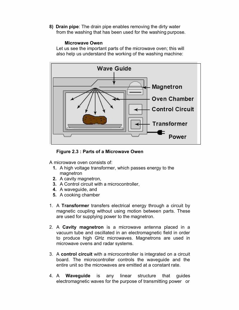
Microwave Owen
Let us see the important parts of the microwave oven; this will also help us understand the working of the washing machine:
Figure 2.3 : Parts of a Microwave Owen
A microwave oven consists of: 1. A high voltage transformer, which passes energy to the
magnetron 2. A cavity magnetron, 3. A Control circuit with a microcontroller, 4. A waveguide, and 5. A cooking chamber
1. A Transformer transfers electrical energy through a circuit by
magnetic coupling without using motion between parts. These are used for supplying power to the magnetron.
2. A Cavity magnetron is a microwave antenna placed in a
vacuum tube and oscillated in an electromagnetic field in order to produce high GHz microwaves. Magnetrons are used in microwave ovens and radar systems.
3. A control circuit with a microcontroller is integrated on a circuit
board. The microcontroller controls the waveguide and the entire unit so the microwaves are emitted at a constant rate.
4. A Waveguide is any linear structure that guides
electromagnetic waves for the purpose of transmitting power or

signals. Generally constructed of a hollow metal pipe. Placing a waveguide into a vacuum causes radio waves to scatter.
5. A Cooking Chamber is a microwave safe container the
prevents microwaves from escaping. The door has a microwave proof mesh with holes that are just small enough that microwaves can't pass through but lightwaves can. The cooking chamber itself is a Faraday cage enclosure which prevents the microwaves from escaping into the environment. The oven door is usually a glass panel for easy viewing, but has a layer of conductive mesh to maintain the shielding.
Automotive Embedded System (AES) The Automotive industry is one of the major application
domains of embedded systems.
Automotive embedded systems are the one where electronics take control over the mechanical system. Ex. Simple viper control.
The number of embedded controllers in a normal vehicle varies somewhere between 20 to 40 and can easily be between 75 to 100 for more sophisticated vehicles.
One of the first and very popular use of embedded system in automotive industry was microprocessor based fuel injection.
Some of the other uses of embedded controllers in a vehicle are listed below:
a. Air Conditioner
b. Engine Control c. Fan Control
d. Headlamp Control e. Automatic break system control
f. Wiper control g. Air bag control
h. Power Windows
AES are normally built around microcontrollers or DSPs or a
hybrid of the two and are generally known as Electronic Control Units (ECUs).

Types Of Electronic Control Units(ECU) 1. High-speed Electronic Control Units (HECUs):
a. HECUs are deployed in critical control units requiring fast response.
b. They Include fuel injection systems, antilock brake
systems, engine control, electronic throttle,
steering controls, transmission control and central
control units.
2. Low Speed Electronic Control Units (LECUs):- a. They are deployed in applications where
response time is not so critical.
b. They are built around low cost microprocessors
and microcontrollers and digital signal processors.
c. Audio controller, passenger and driver door locks,
door glass control etc.
Automotive Communication Buses Embedded system used inside an automobile
communicate with each other using serial buses. This
reduces the wiring required.
Following are the different types of serial Interfaces used
in automotive embedded applications:
a. Controller Area Network (CAN):- CAN bus was originally proposed by Robert Bosch.
It supports medium speed and high speed data
transfer
CAN is an event driven protocol interface with support
for error handling in data transmission.
b. Local Interconnect Network (LIN):-
LIN bus is single master multiple slave communication interface with support for data rates up to 20 Kbps and is used for sensor/actuator interfacing

LIN bus follows the master communication triggering to eliminate the bus arbitration problem
LIN bus applications are mirror controls , fan controls
, seat positioning controls
c. Media-Oriented System Transport(MOST):-
MOST is targeted for automotive audio/video equipment interfacing
A MOST bus is a multimedia fiber optics point–to- point network implemented in a star , ring or daisy chained topology over optical fiber cables.
MOST bus specifications define the physical as well as application layer , network layer and media access control.
REVIEW QUESTIONS
1. What is an embedded system? What are the working elements of an embedded system?
2. Explain the working of embedded system with respect to: B. Washing Machine C. MICROWAVE Owen
3. Conduct case studies for working of embedded systems for the following topics: A. Air Conditioner B. Automobile

CORE THE OF EMBEDDED SYSTEM
Unit Structure
Objectives Introduction
Core of embedded systems General purpose and domain specific processor.
Microprocessors Microcontrollers. Digital signal processors
Application Specific Integrated Circuits. (ASIC) Programmable logic devices(PLD’s) Commercial off-the-shelf components(COTs) Sensors & Actuators Communication Interface Review Questions References & Further Reading
OBJECTIVES
After reading this chapter you will be able to: Understand the different types of core i.e processor Understand difference between microprocessor &
microcontroller Understand the classification of processors based on Bus
Architecture, Instruction set Architecture and Endianness. Have an overview of processors from most simple and
cheap to most expensive and complex, powerful Understand what are sensors and actuators, communication
interfaces
INTRODUCTION
The first two chapters attempted on explain what an embedded system is about and what the working parts are. This chapter attempts to go deeper and explain the core of embedded system along with other related topics.

CORE OF EMBEDDED SYSTEMS
Embedded systems are domain and application specific and are built around a central core. The core of the embedded system falls into any of the following categories:
1. General purpose and Domain Specific Processors
Microprocessors Microcontrollers Digital Signal Processors
2. Application Specific Integrated Circuits. (ASIC) 3. Programmable logic devices(PLD’s) 4. Commercial off-the-shelf components (COTs)
GENERAL PURPOSE AND DOMAIN SPECIFIC
PROCESSOR.
• Almost 80% of the embedded systems are processor/ controller based.
• The processor may be microprocessor or a microcontroller
or digital signal processor, depending on the domain and application.
MICROPROCESSORS A microprocessor is a silicon chip representing a central
processing unit.
A microprocessor is a dependent unit and it requires the combination of other hardware like memory, timer unit, and interrupt controller, etc. for proper functioning.
Developers of microprocessors.
o Intel – Intel 4004 – November 1971(4-bit). o Intel – Intel 4040. o Intel – Intel 8008 – April 1972. o Intel – Intel 8080 – April 1974(8-bit). o Motorola – Motorola 6800. o Intel – Intel 8085 – 1976. o Zilog - Z80 – July 1976.
Architectures used for processor design are Harvard or Von-
Neumann.

20
Harvard architecture Von-Neumann architecture It has separate buses for
instruction as well as data fetching.
Easier to pipeline, so high
performance can be achieve. Comparatively high cost. Since data memory and
program memory are stored physically in different locations, no chances exist for accidental corruption of program memory.
It shares single common bus for instruction and data fetching.
Low performance as
compared to Harvard architecture.
It is cheaper. Accidental corruption of
program memory may occur if data memory and program memory are stored physically in the same chip,
RISC and CISC are the two common Instruction Set Architectures (ISA) available for processor design.
RISC CISC Reduced Instruction Set Complex Instruction Set
Computing It contains greater number of
instructions. Instruction pipelining feature
does not exist. Non-orthogonal set(all
instructions are not allowed to operate on any register and use any addressing mode.
Operations are performed either on registers or memory depending on instruction.
The number of general purpose registers are very limited.
Instructions are like macros in C language. A programmer can achieve the desired functionality with a single instruction which in turn provides the effect of using more simpler single instruction in RISC.
It is variable length
instruction.
Computing It contains lesser number of
instructions. Instruction pipelining and
increased execution speed. Orthogonal instruction
set(allows each instruction to operate on any register and use any addressing mode.
Operations are performed on registers only, only memory operations are load and store.
A larger number of registers are available.
Programmer needs to write more code to execute a task since instructions are simpler ones.
It is single, fixed length
instruction.
21
Endiannes o Endianness specifies the order which the data is stored in
the memory by processor operations in a multi byte system.
o Based on Endiannes processors can be of two types: 1. Little Endian Processors 2. Big Endian Processors
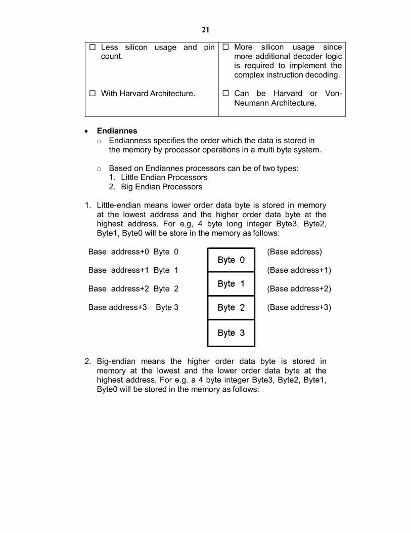
1. Little-endian means lower order data byte is stored in memory
at the lowest address and the higher order data byte at the highest address. For e.g, 4 byte long integer Byte3, Byte2, Byte1, Byte0 will be store in the memory as follows:
Base address+0 Byte 0
Base address+1 Byte 1
Base address+2 Byte 2
Base address+3 Byte 3
(Base address)
(Base address+1)
(Base address+2)
(Base address+3)
2. Big-endian means the higher order data byte is stored in memory at the lowest and the lower order data byte at the highest address. For e.g. a 4 byte integer Byte3, Byte2, Byte1, Byte0 will be stored in the memory as follows:
Less silicon usage and pin count.
With Harvard Architecture.
More silicon usage since more additional decoder logic is required to implement the complex instruction decoding.
Can be Harvard or Von-
Neumann Architecture.

22
Base address+0 Byte 3 (Base address)
Base address+1 Byte 2 (Base address+1)
Base address+2 Byte 1 (Base address+2)
Base address+3 Byte 0 (Base address+3)
MICROCONTROLLERS.
A microcontroller is a highly integrated chip that contains a CPU, scratch pad RAM, special and general purpose register arrays,on chip ROM/FLASH memory for program storage , timer and interrupt control units and dedicated I/O ports.
Texas Instrument’s TMS 1000 Is considered as the world’s
first microcontroller.
Some embedded system application require only 8 bit controllers whereas some requiring superior performance and computational needs demand 16/32 bit controllers.
The instruction set of a microcontroller can be RISC or
CISC.
Microcontrollers are designed for either general purpose application requirement or domain specific application requirement.
Digital Signal Processors
DSP are powerful special purpose 8/16/32 bit
microprocessor designed to meet the computational demands and power constraints of today’s embedded audio, video and communication applications.
DSP are 2 to 3 times faster than general purpose
microprocessors in signal processing applications. This is because of the architectural difference between DSP and general purpose microprocessors.

23
DSPs implement algorithms in hardware which speeds up the execution whereas general purpose processor implement the algorithm in software and the speed of execution depends primarily on the clock for the processors.
DSP includes following key units: i. Program memory: It is a memory for storing the program
required by DSP to process the data.
ii. Data memory: It is a working memory for storing temporary variables and data/signal to be processed.
iii. Computational engine: It performs the signal processing
in accordance with the stored program memory computational engine incorporated many specialized arithmetic units and each of them operates simultaneously to increase the execution speed. It also includes multiple hardware shifters for shifting operands and saves execution time.
iv. I/O unit: It acts as an interface between the outside world
and DSP. It is responsible for capturing signals to be processed and delivering the processed signals.
Examples: Audio video signal processing,
telecommunication and multimedia applications.
SOP(Sum of Products) calculation, convolution, FFT(Fast Fourier Transform), DFT(Discrete Fourier Transform), etc are some of the operation performed by DSP.
Application Specific Integrated Circuits. (ASIC)
ASICs is a microchip design to perform a specific and unique applications.
Because of using single chip for integrates several
functions there by reduces the system development cost.
Most of the ASICs are proprietary (which having some trade name) products, it is referred as Application Specific Standard Products(ASSP).
As a single chip ASIC consumes a very small area in the
total system. Thereby helps in the design of smaller system with high capabilities or functionalities.

24
The developers of such chips may not be interested in revealing the internal detail of it .
Programmable logic devices(PLD’s)
A PLD is an electronic component. It used to build digital circuits which are reconfigurable.
A logic gate has a fixed function but a PLD does not have a
defined function at the time of manufacture.
PLDs offer customers a wide range of logic capacity, features, speed, voltage characteristics.
PLDs can be reconfigured to perform any number of
functions at any time.
A variety of tools are available for the designers of PLDs which are inexpensive and help to develop, simulate and test the designs.
PLDs having following two major types.
1) CPLD(Complex Programmable Logic Device):
CPLDs offer much smaller amount of logic up to 1000 gates.
2) FPGAs(Field Programmable Gate Arrays):
It offers highest amount of performance as well as highest logic density, the most features.
Advantages of PLDs :-
1) PLDs offer customer much more flexibility during the design cycle.
2) PLDs do not require long lead times for prototypes or
production parts because PLDs are already on a distributors shelf and ready for shipment.
3) PLDs can be reprogrammed even after a piece of
equipment is shipped to a customer
Commercial off-the-shelf components(COTs) 1) A Commercial off the Shelf product is one which is used 'as-
is'.
2) The COTS components itself may be develop around a general purpose or domain specific processor or an ASICs or a PLDs.

25
3) The major advantage of using COTS is that they are readily available in the market, are chip and a developer can cut down his/her development time to a great extent
4) The major drawback of using COTS components in
embedded design is that the manufacturer of the COTS component may withdraw the product or discontinue the production of the COTS at any time if rapid change in technology occurs.
5) Advantages of COTS:
1) Ready to use 2) Easy to integrate 3) Reduces development time
6) Disadvantages of COTS:
1) No operational or manufacturing standard (all proprietary)
2) Vendor or manufacturer may discontinue production
of a particular COTS product
SENSORS & ACTUATORS
Sensor A Sensor is used for taking Input It is a transducer that converts energy from one form to
another for any measurement or control purpose Ex. A Temperature sensor
Actuator
Actuator is used for output. It is a transducer that may be either mechanical or electrical
which converts signals to corresponding physical actions. Ex. LED (Light Emitting Diode) LED is a p-n junction diode and contains a CATHODE and
ANODE For functioning the anode is connected to +ve end of power
supply and cathode is connected to –ve end of power supply.
The maximum current flowing through the LED is limited by connecting a RESISTOR in series between the power supply and LED as shown in the figure below
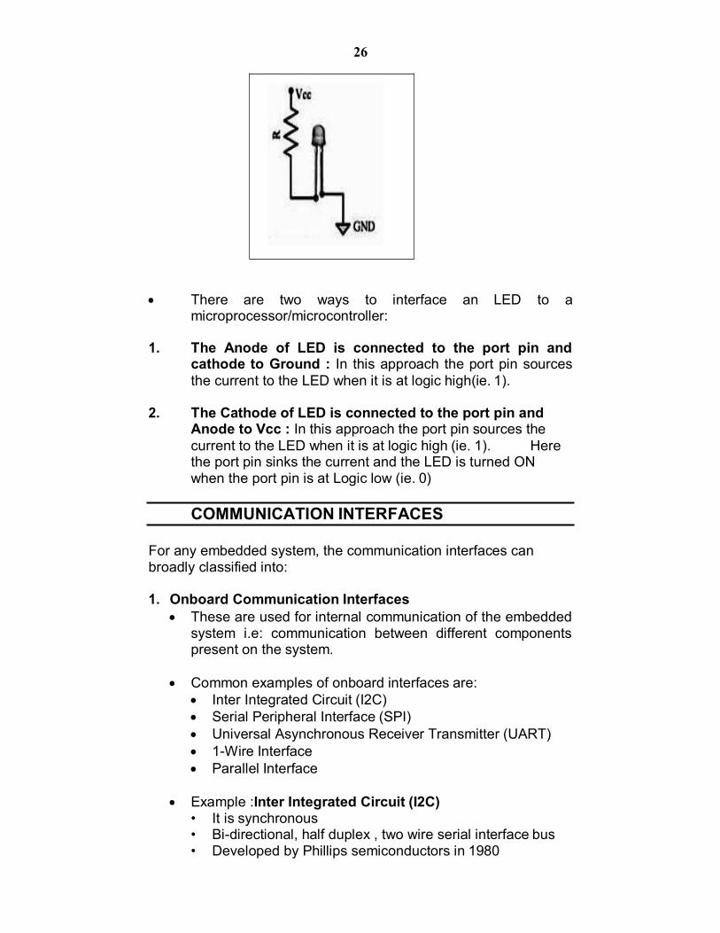
26
There are two ways to interface an LED to a microprocessor/microcontroller:
1. The Anode of LED is connected to the port pin and
cathode to Ground : In this approach the port pin sources the current to the LED when it is at logic high(ie. 1).
2. The Cathode of LED is connected to the port pin and
Anode to Vcc : In this approach the port pin sources the current to the LED when it is at logic high (ie. 1). Here the port pin sinks the current and the LED is turned ON when the port pin is at Logic low (ie. 0)
COMMUNICATION INTERFACES
For any embedded system, the communication interfaces can broadly classified into:
1. Onboard Communication Interfaces
These are used for internal communication of the embedded system i.e: communication between different components present on the system.
Common examples of onboard interfaces are:
Inter Integrated Circuit (I2C) Serial Peripheral Interface (SPI) Universal Asynchronous Receiver Transmitter (UART) 1-Wire Interface Parallel Interface
Example :Inter Integrated Circuit (I2C)
• It is synchronous • Bi-directional, half duplex , two wire serial interface bus • Developed by Phillips semiconductors in 1980

27
• It comprises of two buses : 1. Serial clock –SCL 2. Serial Data – SDA
• SCL generates synchronization clock pulses • SDA transmits data serially across devices • I2C is a shared bus system to which many devices can
be connected • Devices connected by I2C can act as either master or
slave • The master device is responsible for controlling
communication by initiating/ terminating data transfer. • Devices acting as slave wait for commands from the
master and respond to those commands.
Figure: I2C Bus Interfacing
2. External or Peripheral Communication Interfaces These are used for external communication of the
embedded system i.e: communication of different components present on the system with external or peripheral components/devices.
Common examples of external interfaces are:
RS-232 C & RS-485 Universal Serial Bus (USB) IEEE 1394 (Firewire) Infrared (IrDA) Bluetooth Wi-Fi Zig Bee General Packet Radio Service (GPRS) Example: RS-232 C & RS-485

28
It is wired, asynchronous, serial, full duplex communication
RS 232 interface was developed by EIA (Electronic Industries Associates) In early 1960s
RS 232 is the extension to UART for external communications
RS-232 logic levels use: +3 to +25 volts to signify a "Space" (Logic 0) and -3 to -25 volts to signify a "Mark" (logic 1). RS 232 supports two different types of connectors : DB 9 and DB 25 as shown in figure below
RS 232 interface is a point to point communication interface and the devices involved are called as Data Terminating Equipment (DTE) And Data Communications Terminating Equipment (DCE)
Embedded devices contain UART for serial transmission and generate signal levels as per TTL/CMOS logic.
A level translator IC (like Max 232) is used for converting the signal lines from UART to RS 232 signal lines for communication.
The vice versa is performed on the receiving side. Converter chips contain converters for both transmitters
and receivers RS 232 is used only for point to point connections It is susceptible to noise and hence is limited to short
distances only RS 422 is another serial interface from EIA. It supports multipoint connections with 1 transmitter and
10 receivers. It supports data rates up to 100Kbps and distance up to
400 ft RS 485 is enhanced version of RS 422 and supports up
to 32 transmitters and 32 receivers
REVIEW QUESTIONS
1. What do you mean by core of the embedded system? What is its significance? What are the possible options that can be used as a core?
2. Distinguish between Microprocessor & Microcontroller

29
3. Explain the different types of processors according to their system bus architecture
4. Explain the different types of processors according to Instruction set Architecture
5. Explain the different types of processors according to Endianness
6. Write short note on : i. DSP ii. PLD iii. ASIC iv. COTS
7. Explain Communication Interfaces with respect to embedded system
8. Explain the following with example: 1. Onboard communication interface 2. Peripheral communication interface
9. Find out information and write case studies on the following communication interfaces:
i. Infrared ii. WiFi iii. Zigbee iv. UART

DEBUGGING ON EMBEDDED SYSTEMS
Unit Structure Objectives Introduction Downloading the embedded code Debugging the embedded software Remote Debuggers Emulators Simulators
Other Tools Review Questions References & Further Reading
OBJECTIVES
After reading this chapter you will understand: Concept of downloading the embedded code Debugging the embedded software Different possible tools available for debugging Difference between Remote Debugger, Emulator &
Simulator
INTRODUCTION
In the previous chapter we saw how the code or software to be executed on the embedded system (target board) is written on a computer. The resulting code created after subjecting it to be build process is called the binary executable image or simply hex code.
This chapter explains how the hex code is put on the target
board which is referred as downloading and what are the various possible ways of debugging a code meant to run on a embedded system.

DOWNLOADING THE EMBEDDED CODE
The code to be run on the target embedded system is always developed on the host computer. This code is called the binary executable image or simply hex code.
The process of putting this code in the memory chip of the
target embedded system is called Downloading.
There are two ways of downloading the binary image on the embedded system:
1. Using a Device Programmer
A device programmer is a piece of hardware that works in two steps.
Step 1 Once the binary image is ready on the computer, the device programmer is connected to the computer and the binary image is transferred to the device programmer.
Step 2 The microcontroller/microprocessor or memory chip, usually the ROM which is supposed to contain the binary image is placed on the proper socket on the device programmer. The device programmer contains a software interface through which the user selects the target microprocessor for which the binary image has to be downloaded. The Device programmer then transfers the binary image bit by bit to the chip.
2. Using In System Programmer(ISP)
Certain Target embedded platforms contain a piece of hardware called ISP that have a hardware interface to both the computer as well the chip where the code is to be downloaded.
The user through the ISP’s software interface sends the binary image to the target board.
This avoids the requirement of frequently removing the
microprocessor / microcontroller or ROM for downloading the code if a device programmer had to be used.
DEBUGGING THE EMBEDDED SOFTWARE
Debugging is the process of eliminating the bugs/errors in
software. The software written to run on embedded systems may contain
errors and hence needs debugging. However, the difficulty in case of embedded systems is to find
out the bug/ error itself. This is because the binary image you downloaded on the target board was free of syntax errors but

still if the embedded system does not function the way it was supposed to be then it can be either because of a hardware problem or a software problem. Assuming that the hardware is perfect all that remains to check is the software.
The difficult part here is that once the embedded system starts
functioning there is no way for the user or programmer to know the internal state of the components on the target board.
The most primitive method of debugging is using LEDs. This is
similar to using a printf or a cout statement in c/c++ programs to test if the control enters the loop or not. Similarly an LED blind or a pattern of LED blinks can be used to check if the control enters a particular piece of code.
There are other advanced debugging tools like;
a. Remote debugger b. Emulator c. Simulator
Remote Debuggers Remote Debugger is a tool that can be commonly used for:
Downloading Executing and Debugging embedded software
A Remote Debugger contains a hardware interface between the host computer and the target embedded system.
COMMUNICATION LINK
Figure: Remote Debugger
HOST TARGET EMBEDDED SYSTEM

The Software interface of the remote debugger has GUI-based main window and several smaller windows for the source code, register contents and other information about the executing program.
It contains two pieces of software :
Frontend remote debugger It runs on the host computer. It provides the human interface.
Backend remote debugger
Backend remote debugger runs on the target processor. It communicates with the frontend over a
communications link of some sort. It provides for low-level control of the target processor
and is usually called the debug monitor.
Debug monitor is a piece of software that has been designed specifically for use as a debugging tool for processors and chips.
It is automatically started whenever the processor is reset.
It monitors the communication link to the host computer and responds to requests from the remote debugger running there.
One such debugger is the GNU. It was originally designed for native debugger. It performs cross-debugging. Communication between the GDB frontend and debug
monitor is byte-oriented and designed for transmission over a serial connection.
Emulators A Remote debugger is helpful for monitoring and controlling the
state of embedded software prior to downloading it only.
An Emulator allows you to examine the state of the processor on which that program is actually running. It is itself an embedded system, with its own copy of the target processor, RAM, ROM, and its own embedded software
An Emulator takes the place of-or emulates-the processor on
the target board.
Emulator uses a remote debugger for its human interface.
Emulator supports such powerful debugging features such as hardware breakpoints and real-time tracing. Hardware breakpoints allow you to stop execution in response to a wide
variety of events. These events include instruction fetches, memory and I/O reads and writes and interrupts. Real Time tracing allows you to see the exact order in which events occurred, so it can help you answer questions related to specific errors.
ROM Emulator
It is a device that emulates a read only memory device like ICE (in-circuit emulator).
It connects to the target embedded system and communicates with the host.
When a target connection is via a ROM socket to embedded system it looks like any other read only memory. But when it is to the remote debugger it looks like a debug monitor.
Advantages:
There is no need to port the debug monitor code to particular target hardware.
The ROM emulator supplies its own serial or network connection to the host
The ROM emulator is a true replacement for the original ROM, so none of the target’s memory is used up by the debug monitor code
Simulators
A simulator is a completely host-based program that simulates the functionality and instructions set of the target processor.
Advantage: A Simulator can be quite valuable in the earlier stage of a project when there has not yet been any actual hardware implementation for the programmers to experiment with.
Disadvantage: One of the disadvantages of simulator is that it only simulates the processors.
OTHER TOOLS
Logic Analyzers and Oscilloscopes are very important debugging tools.
Logic Analyzers
It is a piece of laboratory equipment that is designed especially for troubleshooting digital hardware.
It can have multiple inputs (up to 100 even), each capable of
detecting whether the electrical signal it is attached to is currently at logic level 1 or 0
An oscilloscope is another pieces of laboratory equipment of hardware debugging. But this one is used to examine any electrical signal, analog or digital, on any piece of hardware
Oscilloscopes
An oscilloscope is another pieces of laboratory equipment of hardware debugging. But this one is used to examine any electrical signal, analog or digital, on any piece of hardware
Oscilloscope are sometimes useful for quickly observing the
voltage on the particular pin or, in the absence of a logic analyzer, for something ,more complex
REVIEW QUESTIONS
1. Explain the process of Downloading embedded software code
2. Write short note on debugging the embedded software code
3. Explain the working of Remote Debugger 4. Explain the working of Emulator 5. Explain the use of Simulators, Logic analyzers and
Oscilloscopes in debugging embedded systems.

EMBEDDED HARDWARE FROM SOFTWARE PROGRAMMERS
PERSPECTIVE
Unit Structure Objectives Introduction Components on an embedded system Memory Map I/O Map Interrupt Map Review Questions References & Further Reading
OBJECTIVES
After reading this chapter you will be able to: Understand in general the difference in programming software
for general purpose computers and embedded systems The way in which processor communicates with components of
embedded system Memory Map, I/O Map & Interrupt Map
INTRODUCTION
The software programmer must know the hardware involved in an embedded system before he can even attempt to write code for its functioning.
Programming for embedded systems is different than
programming on computers. Embedded systems have certain strict assumptions to be followed. Until the programmer does not know what hardware components are involved and what are the assumptions and rules related to those components, the program or code cannot be written.
This chapter introduces the reader with the hardware of
embedded system from a software perspective. It is this where the

reader shall understand where the code fits in an embedded system.
COMPONENTS ON AN EMBEDDED SYSTEM
Before the programmer can start to code anything, he has to invest some time in understand the functioning of the embedded system.
He is expected to understand the following things:
a. Functioning or purpose of the embedded system b. Individual components involved c. The way data flows through the components of an
embedded system.
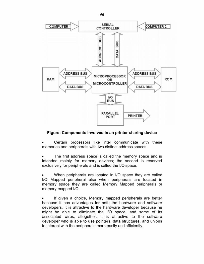
Consider an example of an embedded system intended to be used as a printer-sharing device. This device is attached to a printer and allows access to two computers through serial interface and one printer through a parallel interface.
The diagram below describes the way the devices are connected to each other. Data to be printed is accepted from either serial port, held in RAM until the printer is ready for more data, and delivered to the printer via the parallel port. The software that makes all of this happen is stored in ROM.
The working or execution of the code is brought about by the processor. The processor knows two types of components: memory and peripherals.
Memories are for data and code storage and retrieval. Ex. RAM & ROM
Peripherals are specialized hardware devices that either coordinate interaction with the outside world (I/O) or perform a specific hardware function. Ex. Serial Port
50
Figure: Components involved in an printer sharing device
Certain processors like intel communicate with these memories and peripherals with two distinct address spaces.
The first address space is called the memory space and is intended mainly for memory devices; the second is reserved exclusively for peripherals and is called the I/O space.
When peripherals are located in I/O space they are called I/O Mapped peripheral else when peripherals are located in memory space they are called Memory Mapped peripherals or memory mapped I/O.
If given a choice, Memory mapped peripherals are better because it has advantages for both the hardware and software developers. It is attractive to the hardware developer because he might be able to eliminate the I/O space, and some of its associated wires, altogether. It is attractive to the software developer who is able to use pointers, data structures, and unions to interact with the peripherals more easily and efficiently.
51
MEMORY MAP
A Memory Map is the processor's "address book." It shows what these devices look like to the processor. The memory map contains one entry for each of the memories and peripherals that are accessible from the processor's memory space.
All processors store their programs and data in memory.
These chips are located in the processor's memory space,
and the processor communicates with them by way of two sets of electrical wires called the address bus and the data bus. To read or write a particular location in memory, the processor first writes the desired address onto the address bus. The data is then transferred over the data bus.
A memory map is a table that shows the name and address
range of each memory device and peripheral that is located in the memory space.
Organize the table such that the lowest address is at the
bottom and the highest address is at the top. Each time a new device is added, add it to the memory map, place it in its approximate location in memory and label the starting and ending addresses, in hexadecimal. After inserting all of the devices into the memory map, be sure to label any unused memory regions as such.
The block diagram of the Printer sharing device shown
above contains three devices attached to the address and data buses. These devices are the RAM and ROM and a Serial Controller.
Let us assume that the RAM is located at the bottom of
memory and extends upward for the first 128 KB of the memory space.
The ROM is located at the top of memory and extends
downward for 256 KB. But considering the ROM contains two ROMs-an EPROM and a Flash memory device-each of size 128 KB.
The third device, the Serial Controller, is a memory-mapped
peripheral whose registers are accessible between the addresses say 70000h and 72000h.

52
The diagram below shows the memory map for the printer sharing device.
FFFFFh
E0000h
C0000h
72000h
7000h
20000h
00000h
For every embedded system, a header file should be created that describes these important features and provides an abstract interface to the hardware. It allows the programmer to refer to the various devices on the board by name, rather than by address.
The part of the header file below describes the memory map
#define RAM_BASE (void *) 0x00000000 #define SC_BASE (void *) 0x70000000
#define SC_INTACK (void *) 0x70001000
#define FLASH_BASE (void *) 0xC0000000
#define EPROM_BASE (void *) 0xE0000000
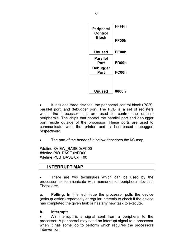
I/O MAP
The I/O map contains one entry for each of the peripheral.
An I/O map has to be created if a separate I/O space is present. It is done by repeating the steps performed to create memory map.
To create an I/O map, simply create a table of peripheral names
and address ranges, organized in such a way that the lowest addresses are at the bottom.
The diagram below shows the I/O map for the printer sharing device
EPROM (128K)
FLASH MEMORY
(128K)
UNUSED
SERIAL CONTROLLER
UNUSED
RAM (128K)
53
FFFFh
FF00h
FE00h
FD00h
FC00h
0000h
It includes three devices: the peripheral control block (PCB), parallel port, and debugger port. The PCB is a set of registers within the processor that are used to control the on-chip peripherals. The chips that control the parallel port and debugger port reside outside of the processor. These ports are used to communicate with the printer and a host-based debugger, respectively.
The part of the header file below describes the I/O map
#define SVIEW_BASE 0xFC00 #define PIO_BASE 0xFD00 #define PCB_BASE 0xFF00
INTERRUPT MAP
There are two techniques which can be used by the processor to communicate with memories or peripheral devices. These are:
a. Polling: In this technique the processor polls the device (asks question) repeatedly at regular intervals to check if the device has completed the given task or has any new task to execute.
b. Interrupt: An interrupt is a signal sent from a peripheral to the processor. A peripheral may send an interrupt signal to a processor when it has some job to perform which requires the processors intervention.
Peripheral Control Block
Unused Parallel
Port Debugger
Port
Unused

54
Upon receiving an interrupt signal the Processor does the job by issuing certain commands and waits for another interrupt to signal the completion of the job.
While the processor is waiting for the interrupt to arrive, it is free to continue working on other things.
When a fresh interrupt signal is received, the processor temporarily sets aside its current work and executes a small piece of software called the interrupt service routine (ISR). When the ISR completes, the processor returns to the work that was interrupted.
The programmer must write the ISR himself and enable it so that it will be executed when the relevant interrupt occurs.
Interrupt Map Embedded systems usually have only a handful of interrupts. Associated with each of these are an interrupt pin which is present on the outside of the processor chip and an ISR.
In order for the processor to execute the correct ISR, a mapping must exist between interrupt pins and ISRs. This mapping usually takes the form of an interrupt vector table.
The vector table is usually just an array of pointers to functions, located at some known memory address. The processor uses the interrupt type (a unique number associated with each interrupt pin) as its index into this array. The value stored at that location in the vector table is usually just the address of the ISR to be executed.
An Interrupt Map is a step taken in this process. The Interrupt Map is a table that contains a list of interrupt types and the devices to which they refer.
The diagram below shows the Interrupt map for the printer sharing device
Interrupt Type Generating Device
8 Timer/Counter #0
17 Serial Controller
18 Timer/Counter #1
19 Timer/Counter #2
20 Serial Port Receive
21 Serial Port Transmit

55
Once the I/O map is created the header file should be appended with the following information:
#define SCC_INT 17 /*Serial Controller*/
#define TIMER0_INT 8 /* On-Chip Timer/Counters*/ #define TIMER1_INT 18 #define TIMER2_INT 19
#define RX_INT 20 /* On-Chip Serial Ports */ #define TX_INT 21
REVIEW QUESTIONS
1. Explain the Components involved in a printer sharing device 2. Explain Memory Map for a printer sharing device 3. Explain I/O Map for a printer sharing device 4. Explain interrupt Map for a printer sharing device

56
EMBEDDED SYSTEMS: MEMORY
Unit Structure
Objectives Introduction Types of Memory Types of RAM SRAM DRAM Types of ROM MASKED PROM EPROM Types of Hybrid Memory NVRAM FLASH EEPROM
DIRECT MEMORY ACCESS (DMA) Review Questions References & Further Reading
OBJECTIVES
After reading this chapter you will understand: Different types of memory available Types of RAM Types of ROM Types of Hybrid Memory
INTRODUCTION
There are different types of memories available to be used in computers as well as embedded system.
This chapter guides the reader through the different types of
memories that are available and can be used and tries to explain their differences in simple words.

57
TYPES OF MEMORY
There are three main types of memories, they are
a) RAM (Random Access Memory) It is read write memory. Data at any memory location can be read or written. It is volatile memory, i.e. retains the contents as long as
electricity is supplied. Data access to RAM is very fast
b) ROM (Read Only Memory)
It is read only memory. Data at any memory location can be only read. It is non-volatile memory, i.e. the contents are retained
even after electricity is switched off and available after it is switched on.
Data access to ROM is slow compared to RAM
c) HYBRID It is combination of RAM as well as ROM It has certain features of RAM and some of ROM Like RAM the contents to hybrid memory can be read
and written Like ROM the contents of hybrid memory are non volatile
The following figure gives a classification of different types of
memory
DRAM SRAM NVRAM Flash EEPROM EPROM PROM Masked
Figure: Types of Memory
M e m o ry
R A M
H yb rid
R O M
58
TYPES OF RAM
There are 2 important memory device in the RAM family. a) SRAM (Static RAM) b) DRAM (Dynamic RAM)
SRAM (Static RAM)
c) It retains the content as long as the power is applied to the chip.
d) If the power is turned off then its contents will be lost forever.
DRAM (Dynamic RAM) a) DRAM has extremely short Data lifetime(usually less than a
quarter of second). This is true even when power is applied constantly.
b) A DRAM controller is used to make DRAM behave more like SRAM.
c) The DRAM controller periodically refreshes the data stored in the DRAM. By refreshing the data several times a second, the DRAM controller keeps the contents of memory alive for a long time.
TYPES OF ROM
There are three types of ROM described as follows:
Masked ROM a. These are hardwired memory devices found on system. b. It contains pre-programmed set of instruction and data
and it cannot be modified or appended in any way. (it is just like an Audio CD that contains songs pre-written on it and does not allow to write any other data)
c. The main advantage of masked ROM is low cost of production.
PROM (PROGRAMMABLE ROM )
a) This memory device comes in an un-programmed state i.e. at the time of purchased it is in an un-programmed state and it allows the user to write his/her own program or code into this ROM.
b) In the un-programmed state the data is entirely made up of 1’s.
c) PROMs are also known as one-time-programmable (OTP) device because any data can be written on it only once. If the data on the chip has some error and needs to be modified this memory chip has to be discarded and the modified data has to be written to another new PROM.

59
EPROM (ERASABLE-AND-PROGRAMABLE ROM) a) It is same as PROM and is programmed in same manner
as a PROM. b) It can be erased and reprogrammed repeatedly as the
name suggests. c) The erase operation in case of an EPROM is performed by
exposing the chip to a source of ultraviolet light. d) The reprogramming ability makes EPROM as essential
part of software development and testing process.
TYPES OF HYBRID MEMORY
There are three types of Hybrid memory devices:
EEPROMs a. EEPROMs stand for Electrically Erasable and
Programmable ROM. b. It is same as EPROM, but the erase operation is
performed electrically. c. Any byte in EEPROM can be erased and rewritten as
desired
Flash a. Flash memory is the most recent advancement in
memory technology. b. Flash memory devices are high density, low cost,
nonvolatile, fast (to read, but not to write), and electrically reprogrammable.
c. Flash is much more popular than EEPROM and is rapidly displacing many of the ROM devices.
d. Flash devices can be erased only one sector at a time, not byte by byte.
NVRAM
a. NVRAM is usually just a SRAM with battery backup. b. When power is turned on, the NVRAM operates just like
any other SRAM but when power is off, the NVRAM draws enough electrical power from the battery to retain its content.
c. NVRAM is fairly common in embedded systems. d. It is more expensive than SRAM.
DIRECT MEMORY ACCESS (DMA)
DMA is a technique for transferring blocks of data directly between two hardware devices.

60
In the absence of DMA the processor must read the data from one device and write it to the other one byte or word at a time.
DMA Absence Disadvantage: If the amount of data to be transferred is large or frequency of transfer is high the rest of the software might never get a chance to run.
DMA Presence Advantage: The DMA Controller performs entire transfer with little help from the Processor.
Working of DMA The Processor provides the DMA Controller with
source and destination address & total number of bytes of the block of data which needs transfer.
After copying each byte each address is incremented & remaining bytes are reduced by one.
When number of bytes reaches zeros the block transfer ends & DMA Controller sends an Interrupt to Processor.
Figure: Direct Memory Access
61
REVIEW QUESTIONS
1. What are the different types of Memory? 2. What are the different types of RAM? 3. What are the different types of ROM? 4. What are the different types of Hybrid Memory?

62
EMBEDDED SYSTEMS: MEMORY TESTING
Unit Structure Objectives Introduction Memory Testing and its purpose Common Memory Problems A strategy for memory testing Data Bus Test Address Bus Test Device Test Review Questions References & Further Reading
OBJECTIVES
After reading this chapter you will be able to understand: What is memory testing? What are the common memory related problems? What are the different types of test to detect memory related
problems and a general idea about the working of these tests
INTRODUCTION
The previous chapter dealt with the different types of memory. This chapter will focus on the concept of testing memory devices, its purpose and different methods available.
MEMORY TESTING AND ITS PURPOSE
The purpose of a memory test is to confirm that each
storage location in a memory device is working. Memory Testing is performed when prototype hardware is
ready and the designer needs to verify that address and data lines are correctly wired and memory chips are working properly.
Basic idea implement in testing can be understood by this simple task:
63
Write some set of Data values to each Address in Memory and Read it back to verify.
Ex. If number ’50’ is stored at a particular Address it is expected to be there unless rewritten or erased.
If all values are verified by reading back then Memory device passes the test.
Only through careful selection of data values can make sure passing result to be meaningful.
Difficulties involved in memory testing: It can be difficult to detect all memory problems with a
simple test. Many Embedded Systems include Memory Tests only
to detect catastrophic memory failures which might not even notice memory chips removal.
COMMON MEMORY PROBLEMS
Memory Problems rarely occur with the chip itself, but due to a variety of post production tests to check quality this possibility is ruled out.
Catastrophic Failure is a memory problem that occurs due to
physical and electrical damage, it is uncommon and easily detectable.
A common source of memory problems is associated with
the circuit board. Typical circuit board problems are: 1. Circuit board wiring between Processor & Memory
device. 2. Missing Memory chip. 3. Improperly inserted Memory chip.
1. Circuit board wiring between Processor & Memory device.
These are usually caused by, i. An error in design ii. An error in production of the board iii. Any damage after manufacture
Wires that connect the memory are:- i. Address line :- select the memory location ii. Data line :- transfer the data iii. Control line :- read or write operation Two wiring problems are shown below
1. Connected to another wire on the board
- May be caused by a bit of solder splash 2. Not connected to anything
- Caused by broken trace

64
Figure: a. wiring problems: two wires shorted b. wiring problems: one wire open
• When Address line has a wiring problem
o memory locations overlap o i.e. memory device to see an address different from the one
selected by the processor. o Problem is with a data line o several data bits “stuck together” o i.e. two or more bits always contains same value
• When the problem is with a Data line
o several data bits “stuck together” o i.e. two or more bits always contains same value o When Control lines is shorted or open
• When Control lines is shorted or open
o The operation of many control lines is specific to the processor or memory architecture.
o the memory will probably not work at all.
2. Missing Memory chip. o A missing memory chip is clearly a problem that should be
detected o Unfortunately, because of the capacitive nature of
unconnected electrical wires, some memory tests will not detect.

65
o For e.g. suppose you decided to use the following test algorithm write the value 1 to the first location in memory, verify the
value by reading it back write 2 to the second location, verify the value write 3 to the third location, verify, etc.
o Because each read occurs immediately after the corresponding write, it is possible that the data read back represents nothing more than the voltage remaining on the data bus from the previous write.
o If the data is read back too quickly, it will appear that the data has been correctly stored in memory-even though there is no memory chip at the other end of the bus!
o To detect a missing memory chip the previous algorithm for test must be altered.
o For example, write the value 1 to the first location, 2 to the second location, And 3 to the third location,
o Then verify the data at the first location, the second location, etc. If the data values are unique (as they are in the test just described), the missing chip will be detected
3. Improperly inserted Memory chip.
Caused by pins on the memory chip o Will either not be connected to the socket at all o Will be connected at the wrong place
Symptoms :-
o System behaves same as though there is a wiring problem or a missing chip.
How to detect :-
o Detected by any test
A STRATEGY FOR MEMORY TESTING
For memory testing the strategy adopted should be effective and efficient. Ideally there should be multiple small tests instead of one large test.
It would be best to have three individual memory tests:
1. A data bus test: Checks electrical wiring problems

66
2. An address bus test: Checks improperly inserted chips 3. A device test: Checks to detect missing chips and
catastrophic failures and problems with the control bus wiring
These tests have to be executed in a proper order which is: data
bus test first, followed by the address bus test, and then the device test. That's because the address bus test assumes a working data bus, and the device test results are meaningless unless both the address and data buses are known to be good.
Data Bus Test
It is used to check data bus wiring. In this test we need to confirm that the received data is same
as the data sent by processor
Implementation: Here we write all possible data values and verify that the
memory device stores each one successfully. In short to test the bus one bit at a time.
Walking 1's test
This test is used to independently test every bit. A single data bit is set to 1 and “walked” through the
entire data word. If the data bus is working properly, the function will return
0. Otherwise it will return the data value for which the test
failed. Because we are testing only the data bus at this point, all
of the data values can be written to the same address. Any address within the memory device will do
00000001 00000010 00000100 00001000 00010000 00100000 01000000 10000000
Figure: Consecutive data values for walking 1's test
67
Address Bus Test Address bus problems lead to overlapping memory locations.
In the Address Bus test we need to confirm that each of the address pins can be set to 0 and 1 without affecting any of the others.
The smallest set of address that will cover all possible combinations is the set of “power of two” addresses.
After writing one of the addresses, we must check none of the others has been overwritten.
Device Test It is used to test if the memory device is working properly. It is
necessary to test the integrity of the memory device itself.
The thing to test is that every bit in the device is capable of holding both 0 and 1.
For a thorough and complete device test every memory location has to be visited twice.
A simple test implemented is the Increment test as shown in the table below The first column represents the memory location The second column represents the data that is written at the
memory location indicated in column 1 in incremental fashion.
The third column represents the data of column 2 in inverted format.
Figure: Data Bus Test – Increment Test

68
During the first pass the data in column 1 is verified and during second pass the data in column 2 is verified.
REVIEW QUESTIONS
1. What is Memory Testing? Why is it required? 2. What are common memory problems in embedded system? 3. Describe a test strategy for performing memory testing on
embedded system. Is there a specific order to perform these tests? if yes, why?
4. Describe the different types of memory testing techniques available.

69
EMBEDDED SYSTEMS: PERIPHERALS
Chapter Structure Objectives Introduction Testing Non Volatile Memory Devices Control and Status Registers Device Driver Watchdog timer Review Questions References & Further Reading
OBJECTIVES
After reading this chapter you will learn: Concept of testing non –volatile memory devices using
Checksum and CRC Control and Status Registers Device Driver Watch Dog Timer
INTRODUCTION
This chapter initially continues the part of memory testing from last chapter. Here testing of Non Volatile memory devices is studied.
Then we study how peripheral devices are incorporated in
Embedded System. Control and Status Registers, Device Drivers and Watch Dog Timers are explained in the subsequent sections.
TESTING NON VOLATILE (ROM AND HYBRID) MEMORY DEVICES
The testing techniques described previously cannot help to test ROM and hybrid devices since ROM devices cannot be written at all, and hybrid devices usually contain data or programs that cannot be overwritten.

70
However ROM or hybrid memory device face the same problems as missing memory chip, improperly inserted memory chip, damaged memory chip or wiring problem with the memory chip.
Two Techniques Checksums and CRC can be used to test
non volatile memory devices.
Checksum Checksums basically deals with the question whether the
data stored in a memory device is valid or not? To do this the checksum of the data in the memory
device is computed and stored along with the data. The moment when we have to confirm the validity of the data, we just have to recalculate the checksum and compare it with previous checksum. If the two checksums match, the data is assumed to be valid.
The simplest checksum algorithm is to add up all the data bytes discarding carries.
A Checksum is usually stored at some fixed location in memory. This makes it easy to compute and store the check sum for the very first time and later on to compare the recomputed checksum with the original one.
Disadvantage: A simple sum-of-data checksum cannot detect many of the most common data errors.
CRC – Cyclic Redundancy Check
A Cyclic Redundancy Check is a specific checksum
algorithm designed to detect the most common data errors.
CRC’s are frequently used in Embedded Applications that requires the storage or transmission of large blocks of data.
The CRC works as follows: The message is composed of a long string of 0’s
and 1’s A division operation occurs between the message
at numerator and the generator polynomial at denominator. The generator polynomial is a fixed smaller length binary string.
The remainder of the division operation is the CRC Checksum

71
CONTROL AND STATUS REGISTERS
Control and status registers are the basic interface between and embedded processor and peripheral device.
These registers are a part of peripheral hardware and their location size and individual meanings are feature of the peripheral.
For example, The registers vary from device to device: example the registers within a serial controller are very different from those in a timer.
Depending upon the design of the processor and target board , peripheral devices are located either in the processor’s memory space or within the I/O space.
It is common for Embedded Systems to include some peripherals of each type. These are called Memory-Mapped and I/O-mapped peripherals.
Of the two types, memory-mapped peripherals are generally easier to work with and are increasingly popular.
Memory-mapped control and status registers can be used just like ordinary variables.
DEVICE DRIVER
The goal of designing a device driver is to hide the hardware
completely. Attempts to hide the hardware completely are difficult. For example all Flash memory devices share the concept of
sectors. An erase operation can be performed only on an entire sector. Once erased individual bites or words can be rewritten.
Device drivers for embedded systems are quite different from the workstation counter parts. In modern computers workstation device drivers are most often concerned with satisfying the requirement of the operating system.
There are three benefits of good device driver:
i. Modularization, it makes the structure of the overall software is easier to understand.
ii. There exists only one module that interacts directly with the peripheral’s registers making communication easier.
iii. Software changes that result from hardware changes are localized to the device driver.

72
Components of a Device Driver A device driver can be implemented (as components) in the
following steps: 1. A data structure that overlays the memory-mapped
control and status registers of the device: This basic step involves creating a C style structure that
is actually a map of the registers present in the device. These registers can be found out by referring to the data sheet for the device.
A table is created which maps the control register to their relative offsets.
An example is shown below for a timer counter data structure.
struct TimerCounter
{ unsigned short count; // Current Count, offset 0x00 unsigned short maxCountA;// Maximum Count, offset 0x02 unsigned short _reserved; // Unused Space, offset 0x04 unsigned short control; // Control Bits, offset 0x06
};
To make the bits within the control register easier to read and write individually, we define the following bitmasks:
#define TIMER_ENABLE 0xC000 // Enable the timer. #define TIMER_DISABLE 0x4000 // Disable the timer. #define TIMER_INTERRUPT 0x2000 // Enable timer interrupts. #define TIMER_MAXCOUNT 0x0020 // Timer complete? #define TIMER_PERIODIC 0x0001 // Periodic timer?
2. A set of variables to track the current state of the
hardware and device driver: It involves listing out the required variables needed to keep track of the state of the hardware and device driver
3. Initialize the hardware: Once the variables to be used are
known the next step in device driver programming is to initialize the hardware. Next functions can be written to control the device.
4. A set of routines that provide an API for users of the
device driver This involves writing different functions that will implement the various tasks listed to be performed by the device.

73
5. Interrupt service routines Once the required functions and routines are coded the thing remaining to be done is to identify and write routines for servicing the interrupts.
WATCHDOG TIMER
It is hardware equipment. It is special purpose hardware that protects the system from
software hangs. Watchdog timer always counts down from some large
number to zero This process takes a few seconds to reset, in the meantime,
it is possible for embedded software to “kick” the watchdog timer, to reset its counter to the original large number.
If the timer expires i.e. counter reaches zero, the watchdog timer will assume that the system has entered a state of software hang, then resets the embedded processor and restarts the software
It is a common way to recover from unexpected software hangs
The figure below diagrammatically represents the working of the watchdog timer
Figure: Watchdog Timer

74
REVIEW QUESTIONS
1. Explain testing for non-volatile memory devices 2. Write short note on Control and status registers 3. What is a device driver? 4. What are the components of a device driver? 5. Write short note on Watch Dog Timer

75
EMBEDDED OPERATING SYSTEM
Chapter Structure Objectives Introduction Basics Tasks Task States Scheduler Scheduling Points Ready List Idle task Context Switch Task Synchronization Real Time Characteristic Selection Process Review Questions References & Further Reading
OBJECTIVES
After reading this chapter you will learn: The basics of embedded Operating system with respect to
1. Tasks 2. Task States
Scheduler with respect to: 1. Scheduling Points 2. Ready List 3. Idle task
Concept of Context Switch and Task Synchronization Real Time Characteristic of embedded operating system.
INTRODUCTION
This chapter introduces the readers to the embedded operating system. Any operating system has a set of programs which are implemented through a set of tasks.
Every embedded system may not require an operating
system. The requirement and complexity on an operating system depends on the functionality to be implemented by the embedded system.

76
BASICS
Tasks Task is a piece of code or program that is separate from
another task and can be executed independently of the other tasks.
In embedded systems, the operating system has to deal with
a limited number of tasks depending on the functionality to be implemented in the embedded system.
Multiple tasks are not executed at the same time instead
they are executed in pseudo parallel i.e. the tasks execute in turns as the use the processor.
From a multitasking point of view, executing multiple tasks is
like a single book being read by multiple people, at a time only one person can read it and then take turns to read it. Different bookmarks may be used to help a reader identify where to resume reading next time.
An Operating System decides which task to execute in case
there are multiple tasks to be executed. The operating system maintains information about every task and information about the state of each task.
The information about a task is recorded in a data structure
called the task context. When a task is executing, it uses the processor and the registers available for all sorts of processing. When a task leaves the processor for another task to execute before it has finished its own, it should resume at a later time from where it stopped and not from the first instruction. This requires the information about the task with respect to the registers of the processor to be stored somewhere. This information is recorded in the task context.
A C++ version of a Task that holds all information needed by
operating system is as follows: class Task {
public: Task(void (*function)(), Priority p, int stackSize); TaskId id; Context context; TaskState state; Priority priority;

77
int * pStack; Task * pNext;
void (*entryPoint)();
}; Task States
private: static TaskId nextId;
In an operation system there are always multiple tasks. At a time only one task can be executed. This means that there are other tasks which are waiting their turn to be executed.
Depending upon execution or not a task may be
classified into the following three states:
Running state - Only one task can actually be using the processor at a given time that task is said to be the “running” task and its state is “running state”. No other task can be in that same state at the same time
Ready state - Tasks that are are not currently using
the processor but are ready to run are in the “ready” state. There may be a queue of tasks in the ready state.
Waiting state - Tasks that are neither in running nor
ready state but that are waiting for some event external to themselves to occur before the can go for execution on are in the “waiting” state.
Figure: Task States
A transition of state between the ready and running state
occurs whenever the operating system selects a new task to run.
The task that was previously in running state becomes
ready and the new task is promoted to running state.
78
A task will leave running state only if it needs to wait for some event external to itself to occur before continuing.
A task's state can be defined as follows:
enum TaskState { Ready, Running, Waiting };
SCHEDULER
• The heart and soul of any operating system is its scheduler. • This is the piece of the operating system that decides which
of the ready tasks has the right to use the processor at a given time.
• It simple checks to see if the running task is the highest priority ready task.
• Some of the more common scheduling algorithms:
1. First-in-first-out First-in-first-out (FIFO) scheduling describes an operating
system which is not a multitasking operating system.
Each task runs until it is finished, and only after that is the next task started on a first come first served basis.
2. Shortest job first
Shortest job first scheduling uses algorithms that will select always select a task that will require the least amount of processor time to complete.
3. Round robin.
Round robin scheduling uses algorithms that allow every task to execute for a fixed amount to time.
A running task is interrupted an put to a waiting state if its
execution time expires.
Scheduling Points The scheduling points are the set of operating system events
that result in an invocation of the scheduler.
There are three such events: task creation and task deletion. During each of these events a method is called to select the next task to be run.
A third scheduling point called the clock tick is a periodic
event that is triggered by a timer interrupt. When a timer expires, all of the tasks that are waiting for it to complete are changed from the waiting state to the ready state.

79
Ready List The scheduler uses a data structure called the ready list to
track the tasks that are in the ready state.
The ready list is implemented as an ordinary linked list, ordered by priority.
So the head of this list is always the highest priority task that
is ready to run.
Idle task If there are no tasks in the ready state when the scheduler is
called, the idle task will be executed.
The idle task looks the same in every operating system.
The idle task is always considered to be in the ready state.
CONTEXT SWITCH
The actual process of changing from one task to another is called Context Switch.
Since contexts are processor-specific, so is the code that
implements the context switches, hence, it must always be written in assembly language.
TASK SYNCHRONIZATION
All the tasks in the multitasking operating systems work together to solve a larger problem and to synchronize their activities, they occasionally communicate with one another.
For example, in the printer sharing device the printer task
doesn’t have any work to do until new data is supplied to it by one of the computer tasks.
So the printer and the computer tasks must communicate
with one another to coordinate their access to common data buffers.
One way to do this is to use a data structure called a
mutex.
Mutexes are mechanisms provided by many operating systems to assist with task synchronization.

80
A mutex is a multitasking-aware binary flag. It is because the processes of setting and clearing the binary flag are atomic (i.e. these operations cannot be interrupted).
When this binary flag is set, the shared data buffer is
assumed to be in use by one of the tasks. All other tasks must wait until that flag is cleared before reading or writing any of the data within that buffer.
The atomicity of the mutex set and clear operations is
enforced by the operating system, which disables interrupts before reading or modifying the state of the binary flag.
REAL TIME CHARACTERISTIC
An Operating system is called “Real-Time Operating System” (RTOS) only if it has following characteristics:
i. Deterministic An OS is said to be deterministic if the worst case
execution time of each of the system calls is calculable.
The data sheet of an OS should publish the real-time behavior of its RTOS provides average, minimum and maximum number of clock cycles required by each system call.
ii. Interrupt Latency
Interrupt Latency is the total length of time from an interrupt signal’s arrival at the processor to the start of the associated interrupt service routine.
iii. Context Switch
Context Switch is important because it represents overhead across your entire system.
SELECTION PROCESS
The process of selecting the best commercial operating system that best fits the needs of one’s project depends on various factors.
Commercial operating systems form a continuum of functionality, performance and price.
Operating Systems that offer only a basic scheduler and
a few other system calls are inexpensive and come with the source code that one can modify and do not require payment of royalties.

81
While on the other hand operating systems that include a lot of useful functionality beyond just the scheduler are quite expensive and royalties due on every copy shipped in ROM and they might also make a stronger guarantees about real-time performance.
Two important points to be considered while selecting an operating system :-
Put your processor, real time performance and budgetary requirements first.
Contact all of the vendors of the remaining operating systems for more detailed technical information.
REVIEW QUESTIONS
1. Explain the embedded Operating system with respect to i) Tasks ii) Task States
2. Explain Scheduler with respect to: i) Scheduling Points ii) Ready List iii) Idle task
3. Write a short note on Context Switch and Task Synchronization 4. Explain the Real Time Characteristic of embedded operating
system.