Embed Size (px)
Citation preview
Embedded Systems:Simple Rules to Improve AdaptabilityManfred Nagl
Department of Computer ScienceTechnical Report
Aachener Informatik-Berichte (AIB) | ISSN 0935-3232 | AIB-2021-04RWTH Aachen University | Department of Computer Science | February 2021
[Nag21c] M. Nagl: Embedded Systems: Simple Rules to Improve Adaptability. In: RWTH Aachen University, Technical Report. AIB-2021-04. Feb. 2021. www.se-rwth.de/publications/

The publications of the Department of Computer Science of RWTH Aachen University arein general accessible through the World Wide Web.
http://aib.informatik.rwth-aachen.de/
1
Embedded Systems: Simple Rules to Improve Adaptability
Manfred Nagl Software Engineering
RWTH Aachen University, 52074 Aachen, Germany
Abstract
Embedded systems have specific properties, which are consequences of the application do-main, namely the close connection to the underlying technical system, the specific challenges of the development process, and the mixture of persons involved in their development, etc. Thus, adaptability (portability, extensibility, and changeability) is more difficult compared to other types of software systems.
The paper addresses the question, what we can be do to improve adaptability of embedded systems. We study different examples of embedded systems. A series of hints is given. Most of them are related to the abstract architecture, i.e. the first result of the design process. The hints are also helpful for higher level tasks, such as integration of embedded systems, devel-oping families of embedded systems, finding opportunities for reuse, and alike.
Key words: embedded systems, dependency of the technical system, adaptability of corresponding software architectures, data abstraction in a generalized sense, variability of the solutions, list of hints for adaptability and variability
1 Introduction
Embedded software systems /BL 18, Ma 21/ have specific characteristics: (i) They live for a long time (20 years and more), they (ii) run “forever” (until they are explicitly stopped, ac-cordingly they have to be started explicitly), they are (iii) highly dependent on the surround-ing technical system they are controlling, they sometimes have (iv) specific parts for emer-gency handling, they have (v) to be efficient and react in short time, they (vi) mostly have to address concurrency and they (vii) are developed together with engineers, in some cases only or mostly by engineers. There are (viii) many technical details in the hardware/ software solu-tion, which determine the solution, as corresponding abstractions are often not introduced in the design and development of the software system. Finally, (ix) many variations correspond-ing to functionality, the structure, and realization of the technical system are possible. The same applies to the software part. (x) Families of systems and not only one system are some-times the goal.
Adaptability is difficult in connection to hardware. Hardware is not easy to change, in many cases it is easier to build it newly. Software can more easily be changed, if it is built in the right way. In many cases, software is designed and constructed in close connection to hard-ware, and thereby inherits the property of inflexibility. This paper gives some hints in the di-rection, what has to be regarded to make the software part adaptable, thereby also improving the adaptability of the overall embedded system. The key are suitable activities on architec-ture level /BK 03, GS 94, HK 07, KM 04, Ru 12, Sc 13, SEI 10, SG 96, SS 00/.
Engineers on one side and IT specialists/ computer scientists on the other have run through a different education. Therefore, they follow a different mental approach to achieve a solution. A combination of both approaches – thinking in complex technical details on one hand and
2
trying to abstract from them to cover the situations, where changes are probable – if possible and useful – would improve adaptability. To demonstrate this, is the most important goal of this paper. The above problems have to be addressed at the beginning of the design and de-velopment process. They cannot be added afterwards.
This article has a specific goal and thus a special motivation, namely to give some hints for embedded systems’ development in direction of achieving adaptability and mastering varia-bility. There are many publications and books for general knowledge on the fundamentals, foundations, and methodology of new modeling approaches, as e.g. /PB 16, PH 12/. This pa-per is the embedded systems supplement of a general software architecture approach /Na 82-03, Na 90, Na 21a/.
The paper is as follows: After the introduction in section 1, in section 2 we discuss a small embedded system on one microcontroller (programmable logical controller, in short PLC) and show, what has to be done for adaptability. Then, we step forward to more complex systems: (a) connected and distributed systems in section 3 (like software in automotive), (b) layered systems (like software for a chemical plant) in section 4. The summary of section 5 contains a list of problems to be addressed in embedded system construction in order to get adaptability in an improved process. All the hints given here are important when designing the more ab-stract logical architecture, so before technical details are studied. All hints apply and are of specific value for a mixed developer crew of engineers and IT specialists. In section 6 we dis-cuss lessons learned and open problems. A list of references closes the paper.
2 Simple Example: A Coffee Maker
Design as Usual
We start out with a simple solution, a coffee machine where the control hardware is only one microcontroller. You see the hardware solution in fig. 1.a, the software design as usual in 1.b, and the design regarding adaptability in fig. 2. Although the example is small, we can learn some basic rules from it.
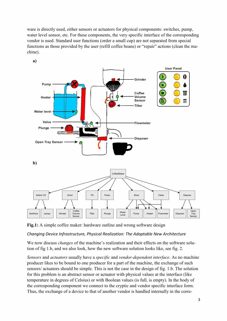
The hardware is shown in fig. 1.a.There is a grinder to provide coffee powder. The amount is regulated by a volume sensor. A tilter transports the powder down to the brewing region. Wa-ter is contained in a reservoir, where a water level sensor says, when to refill. A pump takes the water out of the reservoir, such that it flows through a heating pipe, regulated by a flow meter. The plunge opens the way for the hot water to flow through the powder, in order to brew the coffee. After brewing, the used coffee falls down into the tray container. The open tray sensor says, when it has to be emptied.
The user panel consists of 4 functional buttons: To start the machine, to produce a small or a big cup, and to clean the machine. There are four warning lamps: coffee beans are missing, water is missing, the tray sensor has to be emptied, and the machine has to be cleaned.
Fig.1.b shows a (wrong) software solution (without looking for adaptability). We recognize that the software 1:1 maps the hardware. On the bottom level we see the components to con-trol the used physical devices, as sensors or as actuators. The hardware solution can easily be found in the software solution.
What is wrong? All components are functional units, organized in a tree. A task is split into simpler tasks. Units reflect concrete realization, not more or less abstract functionality. Hard-
3
ware is directly used, either sensors or actuators for physical components: switches, pump, water level sensor, etc. For these components, the very specific interface of the corresponding vendor is used. Standard user functions (order a small cup) are not separated from special functions as those provided by the user (refill coffee beans) or “repair” actions (clean the ma-chine).
a)
b)
Fig.1: A simple coffee maker: hardware outline and wrong software design
Changing Device Infrastructure, Physical Realization: The Adaptable New Architecture
We now discuss changes of the machine’s realization and their effects on the software solu-tion of fig 1.b, and we also look, how the new software solution looks like, see fig. 2.
Sensors and actuators usually have a specific and vendor-dependent interface. As no machine producer likes to be bound to one producer for a part of the machine, the exchange of such sensors/ actuators should be simple. This is not the case in the design of fig. 1.b. The solution for this problem is an abstract sensor or actuator with physical values at the interface (like temperature in degrees of Celsius) or with Boolean values (is full, is empty). In the body of the corresponding component we connect to the cryptic and vendor specific interface form. Thus, the exchange of a device to that of another vendor is handled internally in the corre-
Grinder
User Panel
Water level
Pump
Plunge
Open Tray Sensor
Tilter
CoffeeVolumeSensor
Flowmeter
Disposer
Heater
Valve
CoffeeMaker
Switch I/O Grind Tilt Press Brew DisposeClean
Switches Lamps Water LevelPlunge DisposerHeaterPump
OpenTray
SensorFlowmeterTilterGrinder
CoffeeVolumeSensor
4
sponding abstract sensor/ actuator component and has no effect on upper components. By the way, all such components are abstract data object (ado) components, as they organize a state, and not functional components (f objects). In /PK 09/ we find similar ideas, not for software architectures but for models in a model-driven scenario.
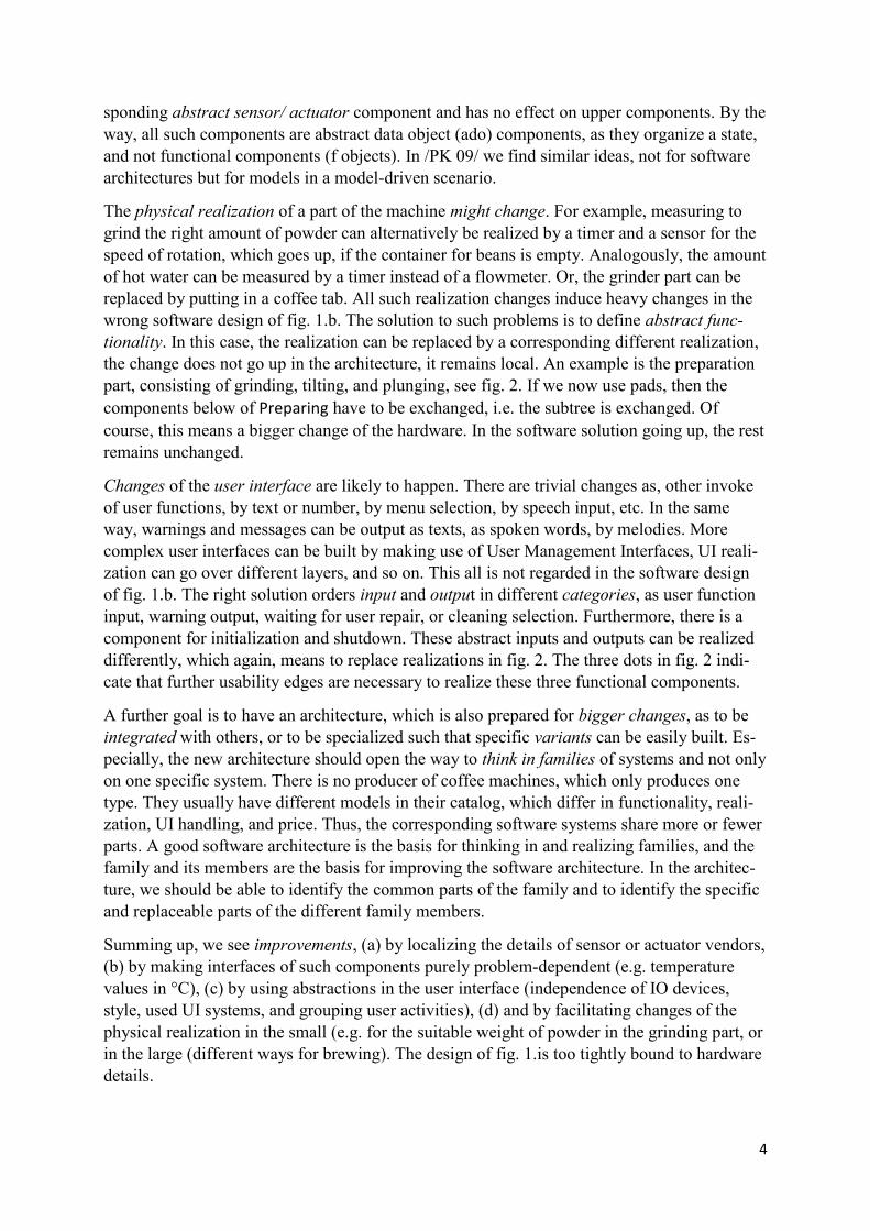
The physical realization of a part of the machine might change. For example, measuring to grind the right amount of powder can alternatively be realized by a timer and a sensor for the speed of rotation, which goes up, if the container for beans is empty. Analogously, the amount of hot water can be measured by a timer instead of a flowmeter. Or, the grinder part can be replaced by putting in a coffee tab. All such realization changes induce heavy changes in the wrong software design of fig. 1.b. The solution to such problems is to define abstract func-tionality. In this case, the realization can be replaced by a corresponding different realization, the change does not go up in the architecture, it remains local. An example is the preparation part, consisting of grinding, tilting, and plunging, see fig. 2. If we now use pads, then the components below of Preparing have to be exchanged, i.e. the subtree is exchanged. Of course, this means a bigger change of the hardware. In the software solution going up, the rest remains unchanged.
Changes of the user interface are likely to happen. There are trivial changes as, other invoke of user functions, by text or number, by menu selection, by speech input, etc. In the same way, warnings and messages can be output as texts, as spoken words, by melodies. More complex user interfaces can be built by making use of User Management Interfaces, UI reali-zation can go over different layers, and so on. This all is not regarded in the software design of fig. 1.b. The right solution orders input and output in different categories, as user function input, warning output, waiting for user repair, or cleaning selection. Furthermore, there is a component for initialization and shutdown. These abstract inputs and outputs can be realized differently, which again, means to replace realizations in fig. 2. The three dots in fig. 2 indi-cate that further usability edges are necessary to realize these three functional components.
A further goal is to have an architecture, which is also prepared for bigger changes, as to be integrated with others, or to be specialized such that specific variants can be easily built. Es-pecially, the new architecture should open the way to think in families of systems and not only on one specific system. There is no producer of coffee machines, which only produces one type. They usually have different models in their catalog, which differ in functionality, reali-zation, UI handling, and price. Thus, the corresponding software systems share more or fewer parts. A good software architecture is the basis for thinking in and realizing families, and the family and its members are the basis for improving the software architecture. In the architec-ture, we should be able to identify the common parts of the family and to identify the specific and replaceable parts of the different family members.
Summing up, we see improvements, (a) by localizing the details of sensor or actuator vendors, (b) by making interfaces of such components purely problem-dependent (e.g. temperature values in °C), (c) by using abstractions in the user interface (independence of IO devices, style, used UI systems, and grouping user activities), (d) and by facilitating changes of the physical realization in the small (e.g. for the suitable weight of powder in the grinding part, or in the large (different ways for brewing). The design of fig. 1.is too tightly bound to hardware details.
5
Fig. 2: The architecture regarding adaptability
The embedded system of above is trivial. We only have one control unit together with sensors and actuators for corresponding devices. Practical Solutions are bigger and much more com-plex: We might have a distributed solution across different hardware components, reaction time plays an important role, the solution for the embedded system will have concurrent com-ponents and thus need synchronization of these components in certain steps, and so on. We are sketching examples of such bigger systems in the next section.
Conclusions
The key is to introduce abstractions. That means to introduce an interface of a component C in the architecture (see fig. 2), which does not rely on details and to provide for exchanging the corresponding realization (the body of C and the needed infrastructure below of this body). This is used for abstractions of state details (how it is represented internally). This is called data abstraction (abstracting from the specific representation of values of sensors or UI structuring details). This is also used for abstracting details of physical realizations (grind 5 grams and leave it open, how this is physically realized). This is called functional abstraction. We see that any abstraction has two aspects: an abstract interface and a realization. We also
CoffeeMakerCoffeeMaker
fo
CoffeeMaker
fo
Waiting forUser RepairWaiting for
User Repair
fo
Waiting forUser Repair
fo
Init/Shutdown
Init/Shutdown
fo
Init/Shutdown
fo
CleaningCleaning
fo
Cleaning
fo
WarningOutput
WarningOutput
fo
WarningOutput
fo
UserFunctions
UserFunctions
fo
UserFunctions
fo
MakingCoffeeMakingCoffee
fo
MakingCoffee
fo
Defect CoffeeMaker
Defect CoffeeMaker
ado
Defect CoffeeMaker
ado
LampsLamps
ado
Lamps
ado
BrewingBrewing
fo
Brewing
fo
Prepare Amount
of Hot Water
Prepare Amount
of Hot Water
fo
Flow HeatWater
Flow HeatWater
fo
Flow HeatWater
fo
DisposingDisposing
fo
Disposing
fo
PreparingPreparing
fo
Preparing
fo
TiltingTilting
fo
Tilting
fo
PlungingPlunging
fo
Plunging
fo
GrindingGrinding
fo
DisposerSensor
DisposerSensor
ado
DisposerSensor
ado
FlowmeterFlowmeter
ado
Flowmeter
ado
Defect CoffeeMaker
Defect CoffeeMaker
ado
Defect CoffeeMaker
ado
TimerTimer
ado
Timer
ado
...
Alternative
foado
functional objectabstract data object
6
see that the realization is not restricted to the body of C, it usually also includes the realization infrastructure below of the component C.
3 Realistic Examples: Distributed Systems
All aspects of above are also important in more complex systems. Thus, the hints of above also apply to them. So, again, functional and data abstraction have to be applied here in the right way. However, we find further and new aspects, for which we have to find solutions.
Multiply connected systems
We regard as an example the software in a car (automotive software). This example is inter-esting from the outside perspective, as (i) a car is a mass product, which has to be inexpen-sive, (ii) every car producer offers a variety of models, any model has a huge amount of vari-ants, (iii) the solutions are a product of many delivering companies and the original equipment manufacturer (OEM). Thus, the solution is (iv) a distributed one, and the solution is devel-oped in a distributed way, too.
It is a miracle that this kid of software works quite well in general. One important reason is that user functions are clearly separated, e.g. to lock/ unlock a car, to start/ stop the engine/ to drive, e.g. go with more or less speed, to steer a car/ to accelerate/ to brake, etc. These catego-ries have connections, but they are not tightly interwoven. In this section of the paper we re-gard a part of the car body system, namely to unlock or lock the car. The example is small, but big enough to learn about embedded systems.
There are various internal problems connected to the example automotive: The target system for the software (hardware architecture) consists (a) of a bigger number (about 50 or more) of control units. These control units are connected (b) by different networks, usually more than one network, for example for motor control, for drive control, etc. These networks can be dif-ferent (CAN, LIN, etc.) and are connected by gateways. Due to the big number of variants (much or few functions) of a model, (c) the hardware architecture can vary as well (fewer number of control units, smaller subnets). This is also true for the software (different number and different sizes of software components). A general problem, therefore (d) is the distribu-tion (software together or distributed) and where to be located (deployment). Thus, (e) it is an enormous problem to keep the development of the various solutions together, from the capa-bility and efficiency point of view. Even bigger (f) is the reuse problem, namely to save and apply the knowledge of solutions from one change of a car model to the successor, or from model to model, as OEMs usually start first in the more expensive models and later transfer to cheaper ones. Finally, (g) there is an actual trend to reduce the number of control units (less and bigger ones) in connection to electrification of cars. Another trend is to produce uniform solutions in big automotive companies, which have different brands. In the long run, this might simplify the solutions, in the short run, it produces further problems as a solution has to be transformed to a different solution.
Conceptual Architecture and Feature Model
How to solve such a complicated problem as indicated in the last subsection? It seems reason-able to start with an abstract architectural description of the solution, which is free of all the specific details of (a) to (g). We call this the conceptual architecture, as it is a solution (can be executed/ interpreted in some way) and not only a specification (only specifying the problem).
7
This solution is a network of functionalities/ services, where the connections correspond to data transfer of parameters, to control transfer (subfunction of, or one function after the other), and also to synchronization (all next functions in parallel, in a controlled schedule, and having situations, where explicit synchronization is necessary). The resulting description is often called a function block model, SysML model, or alike. So, connections represent dependen-cies; in other words, the network is a dependency graph (flow-oriented approach). It also de-scribes the execution order. (It is even better to start with a variation model, as to be explained soon.)
This architecture network is abstract, as it is independent of the steps following below, as how to transform functionalities and connections to software and where to place it on hard-ware. It is important that we do not model details, which belong to the realization or imple-mentation (code level of component bodies) and not to the architecture view. So, a conceptual architecture should not contain details of hardware or software.
It is reasonable to start the design with a feature model, describing the “outside” commonali-ties and the specifics of the different variants of the car model. This feature model describes the family of cars connected with a model of a car, e.g. the 3 series of BMW. That feature model helps to find core functions, which are common for all variants, functions which are specific for a variant, and how functions are built up from common or specific parts. This also helps to find out, which parts are to be placed in the conceptual model, in the software archi-tecture, or hardware architecture. Furthermore, it helps to model in the right way, by separat-ing common parts from specific parts.
It also helps to find the right granularity to model the conceptual architecture, and also for the subsequent architecture models. By the way, the feature model is not only important for the embedded software, but also for the complete design of the car, the mechanical construc-tion, and also for the necessary IT hardware environment of the car in form of sensors and actuators.
In the following, we sketch a rather small part of the automotive functionality, namely the access to the car, i.e. to lock and to unlock the car / WR 11/. Even this part is noticeably sim-plified. A forthcoming paper will demonstrate the different models and their mutual relations from the methodology point of view /MN 21/. Here, we only regard and discuss the example to invent some rules to achieve adaptability.
The example conceptual architecture works in two steps, see fig. 3: (i) Outside the car and from the user side to lock/ unlock, where a component Authenticate is necessary (left part) to validate the user. The corresponding status information is presented by the component LU_Request. (ii) Inside the car or automatic, where this authentication not necessary, the cor-responding status information is delivered by Vehicle_Info. Both inputs (authentified LU_Reqst and Vehicle_Info) have to be brought together (component Combine). Then and in case of contradictions or different priorities, it has to be decided (component Arbitrate). Af-terwards, the decided action takes place, see component Door Locker.
The conceptual architecture regards the feature model, which determines that we regard lock/ unlock in two variants. On the one hand, the user can lock/ unlock from outside by using a remote radio key. The other variant is to use an electronic passport: Whenever he/ she gets near to the car, the car unlocks, if the grip is touched at the driver side. Locking is done by the radio key (simple variant), or if the passport holder has a certain distance to the car (passport
8
variant). In both variants, the functionality as presented in fig. 3 is the same. The variation here only corresponds to the realization of the lock/ unlock mechanism and the comfort of the user interface. Lock/ unlock can also come from inside, as a car has a special button inside lo lock/ unlock.
The information has to be checked dynamically: (a) A door is locked automatically from out-side, if the speed is below 40 km/ h to prevent that somebody opens from outside (robbery in a dangerous city). Or, it is unlocked automatically, if the speed is higher than 40 km/ h. The user can configure such situations in the more expensive cars. (b) In all cars, a car cannot be locked, if a door is open. In all cars (c) a car is automatically unlocked in case of a crash. This information according to (a)(b), and (c) is collected in the component Combine. The compo-nent Arbitrate decides situations of conflict. Here again, we can differ according to variants: Door_Status and Crash_Status are regarded in all variants, the status information Vehi-cle_Speed only in the expensive variant.
So, for Arbitrate there can be different information available, which then is decided by this component: A lock request from outside or inside is ignored, if a door is open or there is a crash. Vehicle_Speed can be the reason of locking/ unlocking (only implemented for expen-sive cars), but explicit lock/ unlock from inside has higher priority. And so on.
State informations as LU_Request and Vehicle_Info are connected by undirected edges in fig. 3 with the corresponding function. They deliver information, as e.g. CL_Reqst for Authenti-cate. This can be done by two mechanisms: Either Authenticate asks LU_Request, or LU_Request in case of a state change causes an interrupt (and activates Authenticate). Both mechanisms mean the same, if we disregard details.
Fig. 3: Conceptual Model for the Access to the Car
As we have seen from this even small example is, the model can be independent of details (as the concrete locking mechanism). But it can regard the different variants and use their infor-mation, as common features for all cars and specific ones for a variant. We have this distinc-tion – common or specific – in mind, and use it for subsequent models.
Software Architecture and Mapping
The conceptual architecture is the guideline for the software architecture to be developed. It is the blueprint to transform the conceptual architecture to software components and relations between these components. This software architecture has at the beginning also an abstract form. For example, no specifics of distribution and following deployment are contained in it. Later forms of this software architecture contain these specifics.
Vehicle_ Info
ArbitrateAuthen-ticate
CL_Reqst
ID
L_Reqst
U_Reqst
L_Reqst
U_Reqst U_Reqst
L_ReqstCombine
Crash_Status
Vehicle_Speed
Door_Status
Unlock
Lock
Unlock
LockLU_
RequestDoor_LockerDoor_Locker
9
How does this abstract form of the software architecture look like, and what are the transfor-mation rules between the conceptual architecture and the (abstract) software architecture? A functionality of the conceptual architecture can be mapped 1:1 on a software component. It can also be that a function is mapped on more software components together with the rela-tions between these components, so on a software subarchitecture. Finally, different function-alities together with their relations (a subarchitecture of the conceptual architecture) can be mapped on one software component, especially if they rely on the same or a similar realiza-tion infrastructure.
Thus, the transformation is not necessarily one to one. The reason is that the conceptual archi-tecture contains functions/ services (what to do, driven by requirements), whereas the soft-ware architecture delivers the structure of a program system, which realizes these services (how to do in the form of a software build plan). Especially, the software architecture also contains components, which cannot be derived from the services, as they belong to deeper layers of the architectural structure. These deeper components or layers are necessary to real-ize the abstract components, which are derived from the conceptual model.
In the example of above, the Authenticate component is in reality more complex, as there are different further ways to request for lock/ unlock, which are not explained above, e. g. there is the mechanical key for worst case handling, etc. Analogously, the Arbitrate has to check many dynamic situations, which depend on many state values, in order to check for an acci-dent. Therefore, in both cases the software architecture might contain more than one compo-nent for both conceptual components. Furthermore, there might be separate infrastructure components in the software architecture, to avoid that the corresponding code for these com-ponents is found multiple times in other components. Therefore, the software architecture can look differently, it is not a 1:1 image of the conceptual architecture.
Physical Architecture
The physical architecture (hardware architecture) consists of connected control units. The control units are different, because they shall realize quite different functionalities in compu-tational demand and also corresponding related requirements. Furthermore, they are deter-mined by subcontractors of the OEM. Control units belonging to one problem area (as motor control) build up a subnet, which might have a specific form and protocol. The different sub-nets are connected by gateways.
Physical architectures can vary, even for the same model of a car, as there are different vari-ants of the model, according to the number of features of this variant. There may be more or fewer control units, or of possibly different computational power, and more extended or sim-pler subnets. So, there are conceptual architectures which have a rich functionality and, ac-cordingly, a rich physical architecture. Similarly, a logical architecture with a poorer func-tionality will have a poorer related physical architecture. The same is true for the software architecture.
In any case, there is a balance between the software and the physical architecture. Both are usually developed “in parallel”. The physical architecture has to answer physical, efficiency, and security aspects and restrictions. The physical architecture is usually built up according to experiences gained in the past: It is usually an extension and modification of a former physi-cal architecture. This is not true if a new situation for the physical architecture is planned (electric car, new approach with fewer control units, see above).
10
Modelling on the level of services (conceptual architecture) and on the level of software com-ponents (software architecture) should have a similar or comparable granularity. The concep-tual model should not contain functionalities of a fine-grained level. Then, the model is a too detailed requirements specification and not a conceptual model. The same is true for the soft-ware architecture. If low-level details would be expressed on architecture level there, the software architecture would contain components, which compose the realization of conceptual or software components, which describe implementation details. Such details should be de-scribed inside of components, i.e. in their bodies and should not appear on architecture level. Or, they should appear as connector components (see abstract sensors or actuators in the cof-fee machine example). Thinking too fine-grained, makes the software architecture also too fine-grained and thus not adaptable.
Distribution and Deployment
Different parts of the software architecture are usually distributed. The first step is to deter-mine, which parts can be placed on different hardware. In this first step, we do not say on which hardware the components are deployed. Instead, we determine by an annotation, that a subarchitecture or software component is placed differently. Distribution is one aspect, which makes the architecture more concrete. Other aspects are concurrency, efficiency transfor-mations, etc. So, the abstract architecture undergoes different stages, see /Na 21b/.
If we have specified distribution, in the next step, which is called deployment, a subarchitec-ture or software component is assigned to a certain control unit to be placed there. It may be, due to efficiency (this part has a higher internal traffic, or this subarchitecture is too much for one control unit) or due to economic reasons (a control unit has open storage place and avail-able runtime resources) that this assignment is split: one part on this control unit, the other on another unit. Therefore, the deployment task is complicated and error-prone, if it is made manually. Please recall that this deployment can be different for different variants of a model.
For our example of above, the components of the software architecture can be deployed to one and big control unit, or to different smaller control units. The parts deployed to a control unit should have a tighter logical coupling compared to those being deployed on different control units. If the code for the car body functions is deployed on different control units, these body components are located on the same bus. Therefore, the deployment maps the parts of the software architecture, which are closer related to each other, to a related part of the hardware architecture.
Deployment has been facilitated by the AUTomotive Open System ARchitecture (AUTOSAR approach) /AU 20/. Here, several program tasks (as routing through the network, introducing program parts for a control unit which listen to the bus to find out, what is essential for this unit or, conversely, to put results of a unit computation on the bus again, are done in a semi-automatic way, i.e. the code is generated according to some specifications by AUTOSAR. That is an enormous progress to the situation before, where these code parts were written in-dividually and manually.
This approach provides flexibility in the distribution and deployment tasks. This flexibility is necessary to handle the many variants of deployments according to the variants of software functionality and the availability of hardware. It also makes backtracking steps easier, which occur after detected errors in every development process. Finally, it also eases reuse in the software between car model families.
11
The discussion of above is simplified: AUTOSAR also helps in the scheduling of software parts on a control unit e.g. according to different priorities. Scheduling was not discussed here. Also, security and safety aspects of software in the car were not addressed here.
The role of Formal / Behavioral Models
For the construction of embedded systems, formal models are used. Usually, they specify the behavior of parts of the system, e.g. in form of Simulink models /Si 20/. The question now is, what are the units, the behavior of which is to be specified? Are the units the services of the conceptual model or the components of the software architecture? In our view, the right units are the components of the software architecture. The Simulink models then specify the behav-ior of the bodies to these components.
From a Simulink specification, code can be generated. This code belongs to the body of the component and specifies the behavioral semantics of this body. The architectural level deliv-ers the glue to combine these different Simulink models. For this kind of integration, the dif-ferent models need not be formally integrated and the generator need not generate code for a large and integrated formal model across different software components. Furthermore, we can integrate components coming from outside, which are not generated, and we can integrate components, which are manually developed, because no model is available, or the generated code was not efficient enough.
Integration of formal models to an integrated formal model is complicated, as models can have different forms, different underlying languages, an integrated model gets large and com-plicated, and no suitable tools are available /BF 10/. Furthermore, the code for the integrated model would have to be separated for deployment.
Summary and Conclusions
The hints of section 2 of above corresponding to sensors, actuators and data or functional ab-straction also apply here. Further hints are as follows.
We start with the variability model. That helps to find similarities and differences. The varia-bility model drives the following conceptual and software models and also the distribution and deployment process. The developers think more in families of solutions than in solutions for a single variant.
For architecture modelling, think first in functionality, not in devices and not in hardware networks, they come later. The conceptual (logical) architecture is free of details, which are probable to change. This architecture is not a detailed requirements specification, where any outside functionality is described in detail.
Modelling the corresponding software architecture has to be done clearly, and also in con-trolled stages from abstract to detailed. It can be supported by tools, and available suitable software should be used. As the software architecture is a build plan, it also contains infra-structure components. This is necessary such that these components are not developed repeat-edly.
In the automotive domain, for conceptual models often data flow networks are used (function blocks, SysML, etc.). Mostly, thereby control loop models are used, e.g. for cruise control. But, it can also be an automata model (Statechart, for describing unlocking and locking of doors), a communication model (for communicating with peer cars or infrastructure), an ab-
12
stract component model (for infotainment or for integrating an overall solution with parts out-side the car). Therefore, the specific models should not be constrained.
The solution of the past and in many cases also of today is that the design process is driven by an enormous amount of problems: the variation problem, the distribution and deployment problem, the selection of control units and the network structure. These problems are tried to be solved nearly at the same time. That makes the design and realization process difficult and it also makes the resulting software system not adaptable. This also makes the maintenance, reuse, and variation problem more complicated than needed.
The solution is to define the conceptual architecture first (directly after the variability model) and make it free of realization details. The (abstract) software architecture is developed next. Using experience from the past, the hardware architecture is modified and extended. Thereby, also a clean structure of the hardware structure should result. The approach AUTOSAR helps for distribution and deployment, i.e. where to place the software components and helping for the details. Thus, for example, modifying the deployment is much easier.
The conceptual architecture and the software architecture should have the right granularity. To develop a feature model for describing the commonalities and differenced of different cars from a family at the beginning, can help to find the right granularity and also to improve re-use, by avoiding that common parts are realized repeatedly. The conceptual and the software architecture should be free of those details, which should be described inside a component, i.e. in the code of the body. Formal and behavioral models as Simulink models should be re-lated to these bodies. In this way, the integration of different models are given by the architec-ture approach described above.
There are strong similarities of embedded software solutions in trucks, rail vehicles, and also somewhat in aircrafts. However, in aircrafts much more powerful and expensive hardware control units are used. The price of an aircraft is much higher than that of a car and the de-mands for security and process regulations are also much higher.
In all these cases, there is also an outside connection to other systems (car and truck: planning and guiding a travel, emergency handling after an accident, automatic drive using an infra-structure; aircraft: automatic flight control, planning and optimizing the route using weather data). These outside systems and their connection are not studied here. The interface of the system to these outside parts should be also clear and free of internal realization details.
4 Processes and Layered Systems
Embedded Systems have Further Challenging Aspects
We now switch the scenario. We have a look on the embedded system inside of a plant, for example in the field chemical engineering or mechanical production. The underlying tech-nical system (chemical plant, production plant or factory) has been developed beforehand, again in different steps starting with a conceptual design and further steps, ending with the detailed design of the plant. Then, the development of the embedded software and the hard-ware system controlling the plant can start, when the factory/ plant design has reached the necessary stability.
The embedded software system is usually a concurrent one. That means that we find process-es (different threads running potentially in parallel), which cooperate with others or compete
13
against others. Therefore, we need means for synchronization and protection. They have to be specified and later implemented by software.
In addition, embedded systems run „for ever“. They are explicitly started and they are explic-itly shut down. This, again, has to be organized by software. Even more, in a case of emer-gency, the system has to be stopped immediately to prevent damages within the plant/ factory. So, further software is necessary to organize this emergency handling.
Summing up, developing the concurrency part, the explicit start/ stop, and emergency han-dling, causes additional effort compared to other software. Thus, embedded software is more complicated and the productivity in code lines per time unit of a developer is much lower. The above remarks also make clear that the design process has to be clearly organized and that the architecture runs through different stages, from abstract to detailed and technical (cf. /Na 21b/ for rules how to organize these stages).
Layered Systems
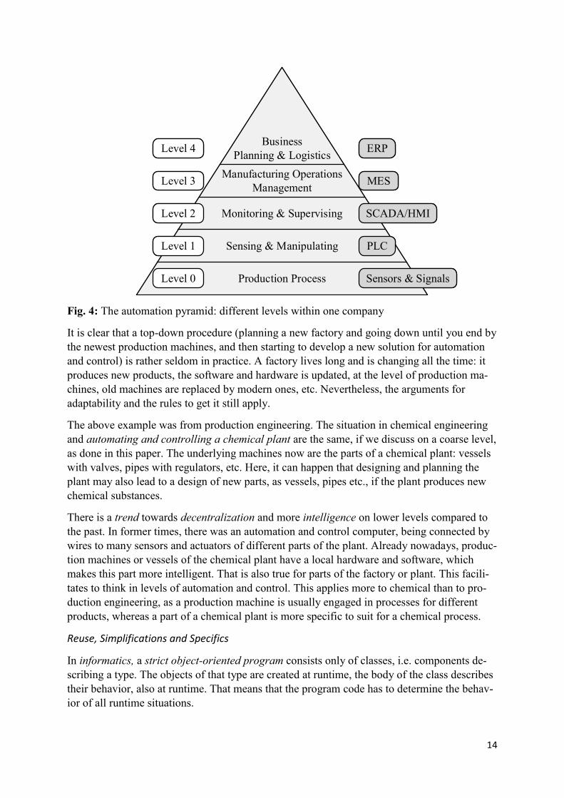
Communication and cooperation in a plant and in the corresponding company are organized in layers. This also applies for the corresponding hardware and especially to the software for automation control and process support /Po 94/. There are many variants of such layer models and the corresponding terminology, see /MP 17/. Fig. 4 shows a variant following /Si 16/. The picture and its terminology is from the mechanical production domain.
We now shortly explain the layers. The lowest level (level 0 in fig. 4) is on top of the produc-tion devices. We get sensor data and send actuator data usually in binary form. One level up, we find sensing and manipulating by programmable logic control (PLC) units. They control and steer a production machine to do complex actions. PLCs and also machines are nowadays connected by a fieldbus (Profibus, Profinet, Modbus, etc.) to avoid tedious wiring. On the next level 2 we monitor and supervise (supervisory control and data acquisition, SCADA), thereby also possibly using human machine interfaces (HMI)). On level 3 complex production steps are integrated by using a manufacturing execution system (MES). As a plant usually produces different products, business planning and logistics are relevant, also because an en-terprise has different plants working together. This is supported by an enterprise resource sys-tem (ERS). In upper levels we often find Ethernet for communication.
We have seen above that an embedded system is connected to its environment, see remarks for vehicles and aircrafts of above. This is also true here. However, the connections are tighter in the fields of production and chemical engineering. Control and automation goes up in the same enterprise from the sheer technical levels of single machines to the level of strategy and financial performance of the whole company. Again, we have different networks, as ProfiBus, as Profinet, etc. in lower levels, and Ethernet in upper levels. Time slices from 10-6 sec to one sec we find on level 0 and 1, up to days and months on level 3 and 4.
For the lower levels 0 to 2 of fig. 4, the arguments are similar to those presented in sections 2 and 3, for the simple example and for the automotive example. The production process has to be planned carefully and, correspondingly, the supporting software for automation and con-trol. You should start by thinking in services and software architectures, distribution of the realization, try to keep in mind upcoming changes and adaptability of the realizations. There-fore and again, we find architectures of different degree of abstraction (at the beginning) and realization (in later stages).
14
Fig. 4: The automation pyramid: different levels within one company
It is clear that a top-down procedure (planning a new factory and going down until you end by the newest production machines, and then starting to develop a new solution for automation and control) is rather seldom in practice. A factory lives long and is changing all the time: it produces new products, the software and hardware is updated, at the level of production ma-chines, old machines are replaced by modern ones, etc. Nevertheless, the arguments for adaptability and the rules to get it still apply.
The above example was from production engineering. The situation in chemical engineering and automating and controlling a chemical plant are the same, if we discuss on a coarse level, as done in this paper. The underlying machines now are the parts of a chemical plant: vessels with valves, pipes with regulators, etc. Here, it can happen that designing and planning the plant may also lead to a design of new parts, as vessels, pipes etc., if the plant produces new chemical substances.
There is a trend towards decentralization and more intelligence on lower levels compared to the past. In former times, there was an automation and control computer, being connected by wires to many sensors and actuators of different parts of the plant. Already nowadays, produc-tion machines or vessels of the chemical plant have a local hardware and software, which makes this part more intelligent. That is also true for parts of the factory or plant. This facili-tates to think in levels of automation and control. This applies more to chemical than to pro-duction engineering, as a production machine is usually engaged in processes for different products, whereas a part of a chemical plant is more specific to suit for a chemical process.
Reuse, Simplifications and Specifics
In informatics, a strict object-oriented program consists only of classes, i.e. components de-scribing a type. The objects of that type are created at runtime, the body of the class describes their behavior, also at runtime. That means that the program code has to determine the behav-ior of all runtime situations.
Production Process
Sensing & Manipulating
Monitoring & Supervising
Manufacturing Operations Management
BusinessPlanning & Logistics ERP
MES
SCADA/HMI
Sensors & Signals
Level 4
Level 3
Level 2
Level 1
Level 0
PLC
Production Process
Sensing & Manipulating
Monitoring & Supervising
Manufacturing Operations Management
BusinessPlanning & Logistics ERP
MES
SCADA/HMI
Sensors & Signals
Level 4
Level 3
Level 2
Level 1
Level 0
PLC
15
In the domain process engineering and control, but also in other domains, there is sometimes a different development process, which is also named object-oriented. The process falls into two parts. In the first part, which we call knowledge or domain development or design, the different types of object of that domain/ company /department are built up as classes, together with their similarities and differences. This is an inheritance and classification hierarchy.
In the second step a specific solution for a problem is constructed by taking objects of these classes and connecting them to a solution. That is again a design process. Therefore, two dif-ferent roles are involved in this two-level design process: the knowledge engineer for the do-main and the designer for a specific solution in the domain. Please note, that the two-level process can be used for process design (chemical plant, production factory) as well as for the automation and control part for this process (a program and its components controlling this plant).
In the field automation and control libraries of many software components are available, to be used for an automation and control solution, see standards of IEC and DIN. These are typical components for different forms of controllers in graphical or textual forms. In addition, there are components and tools for connecting controllers to bigger automation and control solu-tions. The motto of this approach is configuration instead of programming a solution.
Both, the two-level design process and the libraries for process control elements as well as the tools for their construction and combination, are valuable reuse approaches.
At the beginning of this section, we mentioned processes with different threads and synchro-nization of these processes as typical units of an embedded system. In practice, the solution is often simpler. This is true for automotive solutions (section 3) as well as for layered solutions (this section). A task and its subtasks are carefully investigated according to their runtime demands. If they all together are below of the wanted reaction time, they are regarded as a sequence with a fixed schedule. A loop is regarded as a repetitive sequence, etc. The control flow can also be organized via signals (see automotive). This simple solution works well, if the necessary precautions are taken.
We have only sketched two examples of more complex and practical embedded systems in the last two sections, namely highly distributed (automotive software systems) and multiply layered software systems (chemical plant, production plant or factory). Of course, any further application domain introduces further specifics and solutions, which deliver further hints, how to build a solution in the right way.
Conclusions
An automation and control system is tightly connected to the underlying technical system. Therefore, this underlying system should have a clear structure. The automation and control solution refers to this structure, but it should not depend on its internal details. Embedded systems are more complicated than other software systems, as they have to implement start/ stop, emergency handling, and they have to answer the concurrency nature. Instead of pro-cesses and explicit synchronization, often simpler solutions with a fixed schedule are found in practice. They demand for precautions to assure reaction time and synchronization con-straints. Also, the behavior should not be determined by the schedule.
Communication, automation and control, and also the corresponding solution in hardware and software are organized in layers, see the automation pyramid. It has to be decided, on which
16
level a certain functionality is placed. Also, the interfaces between the layers have to be care-fully designed and implemented. From above, one should not see the details of lower levels, or in other words, details should never go up. Connections to outside should also go over clear interfaces. For example, planning a route for trucks can use constraints of the truck as the steepness or the tight turning cycle of a street the vehicle can go. But it should not use details of the truck itself or of its control system.
In layered systems “outside” connections are within the same company, see pyramid. So, clear interfaces and abstraction from details are even more important. In layered systems, we find the architectural problems on different layers and, in addition, we find it between these layers
The design and development of the embedded software system depends on the technical sys-tem. The latter has to be clear beforehand. This technical system has been designed and devel-oped specifically (a new plant for novel chemicals) or is configured from bought production machines (factory). In both cases the technical system can change and, therefore, also the re-quirements for the embedded system (hardware and software). The trend for solutions of the hardware and software for automation and control is decentralization and non-monolithic so-lutions. Machines / devices and bigger parts of the plant/ factory get more intelligent. Adapt-ability and variability is important for all the parts of the automations and control solution to answer to changes of the underlying technical system.
Reuse is also important for solutions of a specific domain, if these solutions are built quite often. A two-level design and realization process (knowledge design and specific solution design) is helpful, as the knowledge part sums up the experiences of former solutions. That can directly be reused. Also, libraries of parts for solutions and tools to combine components to solutions are helpful. Then, building a solution is more a configuration than a programming task.
5 Summary
We now summarize the hints and rules we have discussed for the examples of above in form of a memory list. Where should we pay attention in a development process for embedded sys-tems on architecture level, in order to get adaptable systems and to master the variability due to the many technical details?
Coffee Machine – an Introductory Example
x Sensors and actuators should not have a vendor specific form: abstract from this form. x Clear physical values should appear in interfaces of sensors, actuators (but also other
components), temperature in C or K, pressure in bar, etc. In the body you can connect to a specific sensor or actuator in a way, which can easier be changed.
x For any physical subprocess (as melting or brewing in the coffee maker example) ab-stract from the underlying physical realization.
x Separate usual functions from error handling/ reacting on errors/ start or stop. x Make the user interface independent of how values and decisions are input. Thus, make
the IO part adaptable: abstract from the form of text, clicking in a menu, number, or any other input, abstract from UI system style of input, etc. The client components of the UI system should only know, what has been selected, what has been put in or out, but not how this is done, styled, or with which layout.
17
Automotive
x Start with a variability model, e.g. a feature diagram. That helps to identify the common parts and the specific parts of the following architectures. So, it helps to find the family characteristics. It also helps to find the units, which should appear in the architectural notations.
x Make the conceptual architecture as a network of services (what to do but not how in detail): Find the right abstraction level for these services, which corresponds in its gran-ularity to that of software architecture components. No details (technical details, realiza-tion details) should appear here.
x The software architecture is in its first form an abstract one, i.e. free of specifics as distribution, concurrency, efficiency, etc. These specifics are introduced in later stages. As in every software architecture, there is tight coupling inside components and looser coupling between components.
x Clearly distinguish between the architecture level and the later implementation level. Also, as already told, clearly distinguish between conceptual and software architecture level. Realization components, e.g. infrastructure components or layers, should not ap-pear in the conceptual architecture.
x Think about software components according to the services, the mapping from concep-tual architecture to the software architecture: services are 1:1 mapped, bundled, or ser-vices are split in order to get the components of the software architecture. There should be clear decisions for the mapping from the conceptual to the software architecture.
x In the conceptual architecture and in the software architecture do not model behavioral details, which correspond to the internals of the corresponding units (the bodies to be constructed later). So, do not model realization and implementation details (which cor-respond to the code level) in architectures. This also applies to hardware details.
x Formal models, like Simulink models, in our view correspond to components of the conceptual and even more likely to those of the software architecture. They correspond to the behavior of these components, i.e. to their bodies. By code generation you can get the code of these bodies. The integration of the different components is ensured on ar-chitecture level, not between the formal models. The models can have different underly-ing notations (Statechart, control loops, communication protocols, etc.).
x The software architecture has to offer interfaces for the integration of external parts, for example for functionalities in the case of accidents (delivering information for rescue organizations, announcing serious injuries to hospitals, warnings to cars behind a curve that an accident has happened, etc.).
x Forget in the first steps about the underling network of control units, their subnetworks, their protocols (altogether the hardware architecture): we are first handling the abstract software architecture.
x Think about distribution, and where to group software components, or where to distrib-ute software components.
x Think about the hardware architecture, which control units, which networks are availa-ble, and which gateways to combine subnets. What preparations have to be made for safety and security. The hardware architecture is developed “in parallel” to the software architecture. This demands for hardware experience to avoid big change loops, such as the hardware arch does not fit, or the hardware architecture cannot handle the variability problem.
18
x Think about deployment of software components or groupings of such components into the hardware architecture. Tight coupling has to be answered by putting coupled com-ponents into one control unit or putting them to another control unit on the same subnet.
x Approaches like AUTOSAR /AU 20/ make the above steps distribution and deployment much easier and make the mapping more flexible.
x Introducing abstractions begins already in the feature model, continues in the conceptu-al architecture, and has to be applied for all the steps of above.
Layered systems; Production and Chemical Plants
x Plant/ factory design must be fixed before starting the design of the automation and con-trol part, either in hardware or software. If a plant/ factory of a certain kind is often real-ized and in different forms, it helps to start with a variability model to find out the fami-ly characteristics.
x There should be a clear structure of underlying technical system, either plant or factory. Otherwise, automation and control is not clear. Software cannot repair a bad plant de-sign. It is also getting bad.
x The software part of the embedded system should start with a logical and abstract form, then introduce concurrency, then start/ stop, then emergency handling, as any further form relies on the preceding ones. The sequence should be organized according to, ab-stract is left, aspects more likely to change are right /Na 21b/.
x If a solution does not use processes and synchronization but a simplification with a fixed schedule. Precautions in direction efficiency and security have to be made.
x The solution is organized in layers, see the automation pyramid. Make clear that the functionality of automation and control you are realizing, is on the right layer. It is not using higher functionality, and also not indirect lower realization functionality. It may use the interfaces of the next layer.
x For the lower layers 0, 1, and 2 the rules of above (simple example and automotive ex-ample) apply as well.
x The components needed in higher levels of each layer should have clear interfaces. Re-alization details should not go up or, in other words, they should not be accessible from higher layers.
x From layer to layer upwards: do not spread lower level knowledge upwards and upper level knowledge downwards. In both cases you hinder flexibility. The presented ap-proach is based on a clear layering of control functionalities: Who is controlling what, that determines the considerations of actions in a control loop and loops of loops.
x Do not intermix technical automation knowledge (lower and technical levels) with qual-ity assurance, strategy development, business administration, etc.
x If embedded systems of this kind are integrated, be careful which knowledge is visible on both sides of integration. Have clear interfaces on both sides.
x Think about possible changes to happen on all layers and make sure that these changes do not have global consequences. Any severe change of functionalities (other grouping, shift to another level, etc.) means that you run into a big rearrangement problem.
x If you regard an OO design, use the two-level approach, separating domain knowledge design from design of specific solutions.
x If there are libraries for parts of an automation and control solution, use them if they are appropriate. If tools to combine such solutions are available, use them. If there are pos-

19
sibilities to generate code from a specification (available usually only for parts of the solution) make use of it. All these means are good for reuse.
There are further rules if we regard other and further domains. Therefore, the above set of hints is not complete. However, the argumentation will go along the same lines of thought, as that of the three examples of above.
Although we did not go deep into technical problems of embedded systems in this paper, nei-ther in the automotive example nor in the layered example (production factory or chemical plant), we detected a valuable list of rules to improve adaptability. Going deeper will create further hints and rules to apply.
6. Lessons Learned and Open Problems
Experiences and Expectations
Our group has got some experiences with embedded systems: We worked some time about smart homes /Ar 10, Ki 05, No 07, Re 10/, about telecommunication systems /He 03, Ma 05, Mo 09/, Automotive /Me 12, MN 12/, general distributed and concurrent systems /Kl 00/, technical systems with expert systems /Ba 95/, and modelling of automation systems /Mü 03/. Furthermore, there were a lot of publications on informatics and mechanical engineering (e.g. /NW 99, NW 03/), or chemical engineering (e.g. /NM 08/), and others, most of them on tools for the design and development process.
These experiences but also the contents of books on embedded systems led us to study the adaptability of embedded systems or to master the variability of embedded systems. The key to solve these problems is to introduce abstractions, see the above lists in section 5.
By the way, embedded systems are an ideal discipline for cooperation between computer sci-entists and engineers. There are many technical problems to solve, where expertise from the application domains is necessary to achieve a solution. On the other hand, modeling and in-troducing the right form of abstractions is the key to master adaptability and variability. Also, efficiency of the solutions is necessary, which demands knowledge from engineering domains and also Informatics. Engineers and IT people have different approaches. The combination of these approaches is the right way for the solution of embedded systems.
Open Problems
Reuse in Embedded Systems is more difficult than in other systems, due to the many technical details, which appear in any system. Therefore, there is no uniform structure class build plan describing how an embedded system should be built up. Instead, we have different forms, like (a) small systems which can be controlled by one control unit, (b) systems which have a hardware architecture of many and cheap CUs (like automotive of above), (c) those which have powerful and connected control hardware (as in aircrafts), (d) those for big technical plants as chemical or manufacture plants with a layer structure. There exist decentralized forms (every vessel already has a control unit) and more centralized forms (big control hard-ware with many sensors/ actors connected to it), and so on. It would be nice to find abstract build plans as global patterns for all these specific forms or for methodologies to build them up, such that every design delivers experience for the next designs.
If there were such a series of global patterns, then it would be much simpler to decide what you can take as ideas from a given embedded system, if a system in the same or in a similar
20
domain is developed. Even more, one could take parts of the solution (basic layer, some im-portant components, the methodology to develop essential parts, and so on). Thus, reuse of any kind would be easier.
To look on different systems from an abstract view would also make another problem easier, namely to develop system families or product lines /CN 07, Ja 00, PB 05/, which may evolve over the time /LR 19/ or which may even be configured dynamically /LB 17/. For system families, you have to detect similarities in a systematic way. To see which differences are less important as coming up only in a member of the family, which parts are essential and charac-terize the family. To develop one embedded system in a clean way is complicated, as we see from this paper. To develop a set of systems in a clean way with an underlying view of the whole family is even much more complicated. The build plan for the family must contain the commonalities of the whole family, and at the same time indicate the differences between the members of the family. Ideally, the members are configured automatically from a variant/ configuration model
A specific problem for families we find in automotive. The development time of a car is about 6 to 8 years. A car producer usually has several models (and each, as already told, with many variants). So, the embedded system of different models is developed in some order, to avoid to overload the developers on the one hand and to keep them busy on the other. Let us call this order the big cycle. At BMW, for example, the development cycle start with the big 7 model, then comes the 5 model, and so on. At the beginning of this big cycle, the company has to decide, what to reuse from the last big cycle (more methodology than direct product reuse, as the design of the old 7 model is more than 9 years old and many things have changed, either on the feature side, or on the methodology, and also development side) and from the other cars which have been developed after the 7 model, so within the big cycle. Therefore, there is a nice problem in system families, which consist of smaller families: How to organize the results and how to exhaust the knowledge gained in this big cycle for the rest of the cycle and also for the next big cycle.
Model-driven Development (MDD) /PB 16, PH 12, PK 09/ is a more ambitious approach compared to the approach described in this paper. In MDD we start with abstract models de-noted in a suitable language and transform these models into software, ideally in an automatic way by generating the code. This model can be a control loop Simulink model /Si 20/, e.g. for cruise control, which automatically maintains the speed of a car. It can be a Statechart model /Ha 87, St 20/, for example for opening or closing the doors of a car. It can be a specific speci-fication for the communication of the car with other cars or with the infrastructure of the road.
In all these cases, the generator has to be written such that it automatically and always watch-es the hints given in this paper to produce adaptable software. Or, the generated code is put into a framework for components which fulfills the hints. Today we find the generation ap-proach more for partial solutions within an automation and control system, as door locking/ unlocking, cruise control, etc. Therefore, the generation approach has to be integrated into the design and realization process of the whole system, as the control of an automobile or a chem-ical plant. Integration of all models in one overall model and then generating the code out of this integrated model is not realistic /Me 12/. Neither the models, nor the corresponding tools for different models are integrated /BF 10/, nor the generation processes. Therefore, there is some gap between the current state of the art and a smooth integration of the model-based and the adaptability/ variability architectural approach presented in this paper.
21
In our approach, in every step a person is involved. He/ she (the designer, programmer, etc.) follows the hints given above and by the way he/ she makes architectural decisions, achieves adaptability, and masters variability for the resulting system. This is much simpler than a global MDD approach, where the machinery has to be built in such a way, that all these deci-sions can be made automatically by the generator. In addition, as sketched in the last para-graph, the models can be very different or even might be determined from outside. In a solu-tion, the generated code for the different models has to work smoothly together and the archi-tecture should look, as if it were designed by an experienced designer.
Acknowledgement. The author is indebted to Cem Mengi for valuable discussions and for proofreading.
7 References
/Ar 10/ I. Armac: Personalized eHome Systems (in German), Doct. Dissertation, RWTH Aachen Uni-versity , 315 pp., (2010)
/AU 20/ AUTOSAR: AUTomotive Open System ARchitecture, http://www.autosar.org/, Access Dec 2020
/Ba 95/ V. Bacvanski: Integration and Structuring of Expert Systems in Technical Applications, Doct. Dissertation, RWTH Aachen University, 225 pp. (1995)
/BF 10/ M. Broy/ M. Feilkas et al.: Seamless Model Based Development: From Isolated Tools to Inte-grated Model-Based Developments, Proc. IEEE of the IEEE, 98, 4, 526-545 (2010)
/BK 03/ L. Bass/ P. Clements et al.: Software Architecture in Practice, 2nd ed. Addison Wesley (2003), 3rd ed. Pearson (2013)
/BL 18/ O. Bringmann, W. Lange et al.: Embedded Systems (in German), De Gruyter/ Oldenbourg, 3rd ed. (2018)
/CN 07/ P. Clements/ L.M. Northrop: Software Product Lines: Practices and Patterns, 563 pp., 6th ed., Addison Wesley (2007)
/GS 94/ D. Garlan/ M. Shaw: An Introduction to Software Architectures, TR CMU-CS-94-166 (1994)
/Ha 87/ D. Harel: A Visual Formalism for Complex Systems, Science of Computer Programming, 231-274 (1987)
/He 03/ D. Herzberg: Modelling Telecommunikation Systems: From Standard to System Architec-tures, Doct. Dissertation, RWTH Aachen, 305 pp. (2003)
/HK 07/ C. Hofmeister, Phillippe Kruchten et al: A general model of software architectural design derived from five industrial approaches, Journal of Systems and Software 80, 106-126 (2007)
/Ja 00/ M. Jazayeri et al. (Eds.): Software Architecture for Product Families, Addison Wesley (2000)
/Ki 05/ M. Kirchhof: Integrated eHome Low Cost Systems: Processes and Infrastructures (in German), Doct. Dissertation, RWTH Aachen University, 331pp. (2005)
/Kl 00/ P. Klein: Architecture Modelling of Distributed and Concurrent Software Systems, Doct. Dis-sertation, RWTH Aachen University, 237pp. (2000)
/KM 04/ I. Kruger/ R. Mathew: Systematic development and exploration of service-oriented software architectures, 4th Working IEEE/IFIP Conference on Software Architecture (WICSA), 177-187 (2004)
22
/LB 17/ M. Lochau/ J. Bürdek/ S. Hölzle/ A. Schürr: Specification and automatic validation of staged reconfiguration processes for dynamic software product lines, Softw. Syst. Model 16, 125-152 (2017)
/LR 19/ M. Lochau/ D. Reuling/ J. Bürdek/ T. Kehrer/ S. Lity/ A. Schürr/ U. Kelter: Model-Based Roundtrip Engineering and Testing of Evolving Software Product Lines, in R. Reussner et al. (Eds.), Managed Software Evolution, Springer (2019):
/Ma 05/ A. Marburger: Reverse Engineering of Complex Legacy Telecommunication Systems, Doct. Dissertation, RWTH Aachen University, 418 pp. (2005)
/Ma 21/ P. Marwedel: Embedded System Design, 4th ed., Springer (2021)
/Me 12/ C. Mengi: Automotive Software – Processes, Models, and Variability (in German), Doct. Dissertation, RWTH Aachen University, 350 pp. (2012)
/MN 12/ C. Mengi/ M. Nagl: Refactoring of Automotive Models to Handle the Variant Problem, Workshop „Modellbasierte und modellgetriebene Software-Modernisierung“ (MMSM 2012), Soft-waretechnik-Trends 32, 2, 11-12 (2012).
/MN 21/ C. Mengi/ M. Nagl: Methodology for Automotive, forthcoming paper
/Mo 09/ Ch. Mosler: Graph-based Reengineeing of Telecommunication Systems (in German), Doct. Dissertation, RWTH Aachen University, 268 pp., RWTH Aachen University (2009)
/MP 17/ T. Meudt/ M. Pohl et al.: Die Automatisierungspyramide – Ein Überblick, TU Prints, TU Darmstadt (2017)
/Mü 03/ M. Münch: Generic Modeling with Graph Rewriting Systems, Doct. Dissertation, RWTH Aachen, 242 Spp., Shaker-Verlag, Aachen (2003)
/Na 82-03/ M. Nagl: Introduction to Ada (in German), 348 pp., Vieweg (1982), /Na 03/ 6th ed. Soft-ware Engineering and Ada (in German), 504 pp., Vieweg (2003)
/Na 90/ M. Nagl: Software Engineering- Methodological Programming in the Large (in German), 387 pp., Springer (1990), plus further extensions over the time for a lecture on Software Architectures from 1990 to 2020
/Na 21a/ M. Nagl: An Integrative Approach for Software Architectures, Techn. Report AIB 2021-2, 26pp., RWTH Aachen University
/Na 21b/ M. Nagl: Sequences of Software Architectures, Techn. Report AIB 2021-3, 16pp., RWTH Aachen University
/NM 08/ M. Nagl/ W. Marquardt: Collaborative and Distributed Chemical Engineering – From Under-standing to Substantial Design Process Support, IMPROVE, LNCS 4970, 851 pp., Springer (2008)
/No 07/ U. Norbistath: Configuring eHome Systems (in German), Doct. Dissertation, 286 pp. (2007)
/NW 99/ M. Nagl/ B. Westfechtel (Eds.): Integration of Development Systems in Engineering Appli-cations – Substantial Improvement of Development Processes (in German), 440 pp., Springer (1999)
/NW 03/ M. Nagl/ B. Westfechtel (Eds.): Models, Tools, and Infrastructures for the Support of Devel-opment Processes (in German), 392 pp., Wiley VCH (2003)
/PB 05/ K. Pohl, G. Böckle et al.: Software Product Line Engineering, 467 pp., Springer (2005)
/PB 16/ K. Pohl, M. Broy, M. Daemkes, H. Hönninger (Eds.): Adavanced Model-based Engineering of Embedded Systems – Extensions to the SPES 2020 Methodology, Springer, 303 pp. (2016)
23
/PH 12/ K. Pohl, K. Hönninger, H. Achatz, R. Broy (Eds.): Model-based Engineering of Embedded Systems – The SPES 2020 Methodology, Springer, 304 pp. (2012)
/PK 09/ A. Polzer/ S. Kowalewski/ G. Botterweck: Applying Software Product Line Techniques in Model-based Embedded Software Engineering, Proc. MOMPES’09, 2-10 (2009)
/Po 94/ M. Pohlke: Prozessleittechnik, 2nd edition, Oldenbourg (1994)
/Re 10/ D. Retkowitz: Software Support for Adaptive eHome Systems (in German), Doct. Disserta-tion, RWTH Aachen University, 354 pp. (2010)
/Ru 12/ B. Rumpe: Agile Modeling with UML (in German), 2nd ed., 372 pp. Springer (2012)
/Sc 13/ R.F. Schmidt: Software Engineering – Architecture-driven Software Development, 376 pp. Elsevier (2013)
/SEI 10/ Software Engineering Institute of CMU: What Is Your Definition of Software Architecture, https://resources.sei.cmu.edu/library/asset-view.cfm?assetID=513807
/Si 16/ D. Siepmann: (2016): Industrie 4.0 -Technologische Komponenten, in: Einführung und Umset-zung von Industrie 4.0, in A. Roth, (Hrsg.), Berlin Heidelberg, Springer Gabler Verlag, S.47-72 (2016)
/Si 20/ Wikipedia Simulink: https://en.wikipedia.org/wiki/Simulink und http://www.mathworks.com/products/simulink/ , Zugriff 11,2020
/SG 96/ M. Shaw/ D. Garlan: Software architecture: perspectives on an emerging discipline. Prentice Hall (1996)
/SS 00/ D. Schmidt, M. Stal et al.: Pattern-oriented Software Architectures, vol 2 Patterns for Concur-rent and Networked Objects, Wiley (2000)
/St 20/ Wikipedia Statechart: https://en.wikipedia.org/wiki/State_diagram, Zugriff 11, 2020
/WR 11/ H. Wallentowitz/ K. Reif (Eds.): Handbuch Kraftfahrzeugelektronik, Section 6.2, Zugangs- und Berechtigungssysteme, 369 – 379, Springer Vieweg (2011)
Prof. Dr.-Ing Dr. h.c. Manfred Nagl, Emeritus Informatics Department, RWTH Aachen University [email protected]

Aachener Informatik-Berichte
This list contains all technical reports published during the past three years. A complete
list of (more than 570) reports dating back to 1987 is available from
http://aib.informatik.rwth-aachen.de/
or can be downloaded directly via
http://aib.informatik.rwth-aachen.de/tex-files/berichte.pdf
To obtain copies please consult the above URL or send your request to:
Informatik-Bibliothek, RWTH Aachen, Ahornstr. 55, 52056 Aachen,
Email: [email protected]
2018-02 Jens Deussen, Viktor Mosenkis, and Uwe Naumann: Ansatz zur vari-
antenreichen und modellbasierten Entwicklung von eingebetteten Sys-
temen unter Berucksichtigung regelungs- und softwaretechnischer An-
forderungen
2018-03 Igor Kalkov: A Real-time Capable, Open-Source-based Platform for Off-
the-Shelf Embedded Devices
2018-04 Andreas Ganser: Operation-Based Model Recommenders
2018-05 Matthias Terber: Real-World Deployment and Evaluation of Syn-
chronous Programming in Reactive Embedded Systems
2018-06 Christian Hensel: The Probabilistic Model Checker Storm - Symbolic
Methods for Probabilistic Model Checking
2019-02 Tim Felix Lange: IC3 Software Model Checking
2019-03 Sebastian Patrick Grobosch: Formale Methoden fur die Entwicklung von
eingebetteter Software in kleinen und mittleren Unternehmen
2019-05 Florian Gobe: Runtime Supervision of PLC Programs Using Discrete-
Event Systems
2020-02 Jens Christoph Burger, Hendrik Kausch, Deni Raco, Jan Oliver Ringert,
Bernhard Rumpe, Sebastian Stuber, and Marc Wiartalla: Towards an
Isabelle Theory for distributed, interactive systems - the untimed case
2020-03 John F. Schommer: Adaptierung des Zeitverhaltens nicht-echtzeitfahiger
Software fur den Einsatz in zeitheterogenen Netzwerken
2020-04 Gereon Kremer: Cylindrical Algebraic Decomposition for Nonlinear
Arithmetic Problems
2020-05 Imke Drave, Oliver Kautz, Judith Michael, and Bernhard Rumpe: Pre-
Study on the Usefulness of Difference Operators for Modeling Languages
in Software Development
2021-01 Mathias Obster: Unterstutzung der SPS-Programmierung durch Stati-
sche Analyse wahrend der Programmeingabe
2021-02 Manfred Nagl: An Integrative Approach for Software Architectures
2021-03 Manfred Nagl: Sequences of Software Architectures
2021-04 Manfred Nagl: Embedded Systems: Simple Rules to Improve Adaptabil-
ity

2021-05 Manfred Nagl: Process Interaction Diagrams are more than Process
Chains or Transport Networks
2021-06 Manfred Nagl: Characterization of Shallow and Deep Reuse