Embed Size (px)
Citation preview
Intertek Cleeve Road, Leatherhead, Surrey KT22 7SB UK
[email protected] 01372 370900 www.intertek.com
EMC for Functional Safety: Applying Risk Management to EMC
EurIng Keith Armstrong CEng FIET SMIEEE Cherry Clough Consultants
EMC for Functional Safety: Applying Risk Management to EMC
www.intertek.com 2
Author
EurIng Keith Armstrong CEng FIET SMIEEE Cherry Clough Consultants www.cherryclough.com [email protected]
Keith Armstrong graduated in electrical engineering with a B.Sc (Hons.) from Imperial College London in 1972, majoring in analogue circuit design and electromagnetic field theory.
Much of his working life until 1990 involved solving real-life interference problems in high-technology products, systems, and installations, for a variety of companies and organisations in a wide range of industries. Keith has always aimed to make products easy to design and manufacture, work properly, please their users, and make money for their manufacturers. In the mid-1980s he ran the project to develop an entirely new range of microwave test instruments (the 6200 series) for Marconi Instruments, as well as being in charge of all of its hardware design.
In 1990 Keith formed Cherry Clough Consultants and since then has been providing independent consultancy on the cost-effective EMC and safety design and testing of products, systems and installations, of any size and in all applications.
Keith has been a Chartered Electrical Engineer (UK) since 1978, a Group 1 European Engineer since 1988, and a Fellow of the IET (previously the IEE) and Senior Member of the IEEE since 2010. He has written a great many articles and guides, and presented many papers, on EMC design and testing techniques, and on EMC for Functional Safety. He is a past Chair of the IEE’s Professional Group on Electromagnetic Compatibility and a past President of the EMC Industries Association (www.emcia.org), a member of the IEEE’s EMC and Product Safety Societies, has chaired the IET’s Working Group on 'EMC and Functional Safety' since 1997, and is the UK expert appointed to the IEC standards teams working on 61000-1-2 (‘EMC and Functional Safety’), 60601-1-2 ('EMC of Medical Devices') and 61000-6-7 ('Generic standard on EMC for Functional Safety').
Published by kind permission of the EMC Journal: http://www.nutwooduk.co.uk/
EMC for Functional Safety: Applying Risk Management to EMC
www.intertek.com 3
Summary
Without exception, all electrical and electronic technologies emit electromagnetic (EM) energies into their environment. They – and the software or firmware that runs on them – are also without exception susceptible to suffering errors or malfunctions due to interference from EM energies, known as electromagnetic interference (EMI).
Electromagnetic compatibility (EMC) is the scientific/engineering discipline of ensuring that electrical and/or electronic technologies do not emit levels of EM energies that cause excessive EMI. It is also concerned with ensuring that they do not suffer untoward EMI during operation.
The conventional approach to EMC, developed over the last few decades, applies a fixed set of simple tests to new devices, products, equipment, systems or installations. These tests are usually performed in an “EMC test laboratory”, but sometimes on-site (in-situ), and they ignore all considerations of their design, and whether they are likely to maintain their EM characteristics over their anticipated lifetimes.
Achieving ‘functional safety’ means that safety risks due to errors in operation, or malfunctions, will remain no worse than tolerable over the anticipated lifetime.
So, when electronic technologies are used in devices, products, equipment, systems or installations where their errors or malfunctions could have implications for safety – EMC becomes an important aspect of functional safety engineering. Their EM characteristics (emissions and susceptibility) must remain at least adequate, over that period of time.
Apart from EMC, all other functional safety disciplines (including software engineering [1]) now accept that testing alone cannot achieve due diligence. Instead, a risk management approach is required, that controls specification, design, realization (e.g. manufacture, installation, etc.), verification, validation, maintenance, repairs, upgrades and modifications over the lifetime.
However, this understanding has so far not been applied to EMC for functional safety. Despite concerns being raised as long ago as 1995 [2], most safety engineers still incorrectly believe that it is sufficient to simply apply the conventional EMC tests, perhaps with slightly increased test levels.
This brief article describes why the conventional approach to EMC cannot on its own achieve due diligence for functional safety, and goes on to introduce the comprehensive EMC risk management methodology described in detail by the IET’s new guide on EMC for Functional Safety [3].
EMC for Functional Safety: Applying Risk Management to EMC
www.intertek.com 4
To avoid having to repeat the phrase “devices, products, equipment, systems or installations employing electrical and/or electronic technologies, that have implications for functional safety” throughout this brief article, the term “EFS” is used instead, to mean the same as where this acronym is used in [3].
Background
Electronic technologies, including software or firmware, are increasingly being used where they could affect functional safety, in almost all areas of human life.
But all electronic technologies can suffer from errors, malfunctions and even permanent damage due to EMI. In addition, almost all ‘EM environments’ (the totality of all EM phenomena that could occur at a given location) is continually worsening due to the increasing use of electronic technologies.
All modern electronic technologies rely on digital integrated circuits (ICs) containing very large numbers of very tiny transistors. IC manufacturers are continually shrinking the sizes of these transistors, as described by ‘Moore’s Law’ [4]. This shrinking, plus the associated reductions in their operating voltages and hence their logic thresholds, make them more susceptible to EMI. So, for several reasons, the importance of EMI to the achievement of functional safety is increasing.
Published safety standards generally deal with EMC very poorly, if they even cover it at all [5] [6] [7]. The few that do include specific EMC requirements simply apply conventional EMC immunity tests that can never be sufficient for functional safety, as discussed later.
EMC for Functional Safety: Applying Risk Management to EMC
www.intertek.com 5
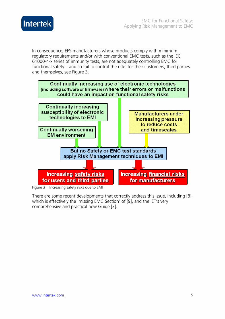
In consequence, EFS manufacturers whose products comply with minimum regulatory requirements and/or with conventional EMC tests, such as the IEC 61000-4-x series of immunity tests, are not adequately controlling EMC for functional safety – and so fail to control the risks for their customers, third parties and themselves, see Figure 3.
Figure 3 Increasing safety risks due to EMI
There are some recent developments that correctly address this issue, including [8], which is effectively the ‘missing EMC Section’ of [9], and the IET’s very comprehensive and practical new Guide [3].
EMC for Functional Safety: Applying Risk Management to EMC
www.intertek.com 6
Why relying on EMC testing cannot achieve due diligence for functional safety
Also see [2] [10] [11] and [12].
Reasonably foreseeable faults are ignored Faults can significantly affect immunity, for example:
• Dry joints, open or short circuits • Out-of-tolerance or incorrect components • Missing or damaged conductive gaskets • Loose/missing fixings in enclosures or cable shielding • Failure of a surge protection device • Intermittent electrical connections
But conventional EMC tests ignore all faults – only perfect EFS specimens are tested. If the EFS sent to the test laboratory turns out to have been manufactured with a fault, the fault is corrected and the perfect specimen tested.
Reasonably foreseeable use and misuse are ignored Functional safety engineering generally accepts that tolerable safety risk levels must be maintained despite reasonably foreseeable use or misuse. It is impossible to make anything perfectly safe – but people are known to behave in certain ways, so safety engineering takes this into account.
But the conventional approach to EMC assumes that an EFS is operated perfectly in accordance with its User Manual at all times.
Conventional test chambers do not simulate the real -life environment Conventional radiated field immunity tests use test chambers that are unlike almost all real-life EM environments experienced by an EFS, so their results can differ markedly from the immunity achieved in real life.
Some EMC test experts have suggested large and unpredictable measurement uncertainties with the conventional test chambers [13] [14]. Reverberation chambers can provide much more realistic tests [15] [16], and for this reason are used by many manufacturers of flight-critical avionics.
Conventional RF modulation types and frequencies do not simulate real-life EMI Most civilian EMC test standards for RF immunity use amplitude modulation with a 1kHz sinewave, for ease of testing, low costs and repeatability. Military and aerospace manufacturers generally use 1kHz squarewave, and some automotive
EMC for Functional Safety: Applying Risk Management to EMC
www.intertek.com 7
manufacturers are starting to employ pulse modulation, intended to simulate digital cellphones and radars at frequencies above 800MHz.
Real-life EM environments contain phenomena with a very wide range of modulation types and frequencies, and [17] and [18] show that immunity can be significantly degraded (e.g. 20dB or more) when EMI modulation corresponds with frequencies or waveforms used in electronic processes, or resonates with circuits, cables, transducers or loads.
The importance of modulation for RF immunity has been well-known in military electronic warfare for decades, and has clear implications for EFS, but is only now just starting to be tentatively addressed by some standards [19] [20].
Simultaneous EM phenomena are not tested Conventional EMC immunity tests apply a limited number of types of EM phenomena, one at a time. But in real-life an EFS is exposed to simultaneous EM phenomena, for example: a distorted AC supply plus a conducted transient or electrostatic discharge; two or more RF fields at different frequencies; a radiated field plus a conducted transient or electrostatic discharge, etc.
Simultaneous EM phenomena are becoming more likely, due to the rapid proliferation of radio-transmitting devices, a development that has worried ICNIRP [21] because like most organizations they have assumed that only one occurs at a time.
EMC for Functional Safety: Applying Risk Management to EMC
www.intertek.com 8
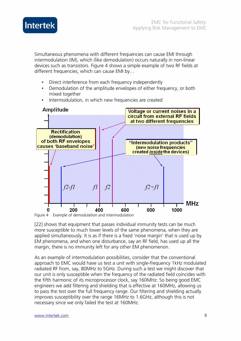
Simultaneous phenomena with different frequencies can cause EMI through intermodulation (IM), which (like demodulation) occurs naturally in non-linear devices such as transistors. Figure 4 shows a simple example of two RF fields at different frequencies, which can cause EMI by…
• Direct interference from each frequency independently • Demodulation of the amplitude envelopes of either frequency, or both mixed together
• Intermodulation, in which new frequencies are created
Figure 4 Example of demodulation and intermodulation
[22] shows that equipment that passes individual immunity tests can be much more susceptible to much lower levels of the same phenomena, when they are applied simultaneously. It is as if there is a fixed ‘noise margin’ that is used up by EM phenomena, and when one disturbance, say an RF field, has used up all the margin, there is no immunity left for any other EM phenomenon.
As an example of intermodulation possibilities, consider that the conventional approach to EMC would have us test a unit with single-frequency 1kHz modulated radiated RF from, say, 80MHz to 5GHz. During such a test we might discover that our unit is only susceptible when the frequency of the radiated field coincides with the fifth harmonic of its microprocessor clock, say 160MHz. So being good EMC engineers we add filtering and shielding that is effective at 160MHz, allowing us to pass the test over the full frequency range. Our filtering and shielding actually improves susceptibility over the range 16MHz to 1.6GHz, although this is not necessary since we only failed the test at 160MHz.
EMC for Functional Safety: Applying Risk Management to EMC
www.intertek.com 9
But in real life our unit is exposed to a number of radiated fields in the unlicensed 2.45GHz band, which is getting very busy these days, which enter our unit and intermodulate in its transistors and diodes, creating new frequencies within its circuitry, on the ‘protected side’ of the filters and shielding we added. If any of the new IM products happen to occur at 160MHz, our unit could malfunction, because it is especially susceptible at that frequency.
Only one port is tested at a time In EMC immunity testing, a “port” is a place where EM energy can enter a unit that is to be tested. In the case of radiated EM phenomena, it is the unit’s enclosure. For conducted EM phenomena, it is a location where a cable enters/exits the unit by penetrating its enclosure.
In real life, all of a unit’s ports are exposed to EM phenomena at the same time, but with slightly different time delays between them. But conventional immunity tests only test one port at a time.
Experiments have injected EM phenomena into all of a unit’s cable ports simultaneously, with delays that correspond to what would be expected between them in real life. They discovered that the immunity could be significantly worse than when one cable was tested at a time, in the conventional manner. Unfortunately this work has not (yet) been published, so no reference is provided.
The physical/climatic environment is ignored To achieve tolerable safety risks, an EFS must maintain appropriate EM characteristics over its anticipated lifetime, despite the effects of the reasonably foreseeable physical and climatic environments over that timescale, including the following issues:
• Mechanical (static forces, shock, vibration, etc.) • Climatic (temperature, humidity, air pressure, etc. – both extremes and cycling effects)
• Chemical (oxidation, galvanic corrosion, conductive dusts, condensation, drips, spray, immersion, icing, etc.)
• Biological (e.g. mould growth, etc.) • Operational ‘wear and tear’ over the lifecycle (friction, fretting, repetitive cleaning, grease build-up, etc.)
Physical effects vary from immediate (e.g. non-flat mounting opening a gap and degrading shielding), to long-term (e.g. corrosion of a shield joint or filter ground bond). [23] describes a number of real-life problems of this nature.
[24] shows that up to 20dB degradation in filter attenuation can be caused by combinations of ambient temperature, supply voltage and load current within the filter’s ratings – compared with the results of conventional immunity tests.
EMC for Functional Safety: Applying Risk Management to EMC
www.intertek.com 10
Some EFS manufacturers perform highly-accelerated life tests to ensure that functionality will be maintained over the lifecycle, but the resulting ‘aged’ units are generally not tested to see if their EM characteristics have been degraded, as they almost certainly will have been [25] [26].
Good EM design engineering is ignored Most manufacturers design their products to function correctly, without thinking very much about designing for EMC. Towards the end of their projects’ development stages they start to do conventional EMC testing, iterating their designs until they pass. This approach is very wasteful indeed of cost and time, and often results in less cost-effective products than would be the case if good EM design techniques had been used from the start.
More worrying, from the point of view of functional safety, is that this approach might not reveal whether the (eventual) pass was achieved by good EM design engineering, or by something that would not be adequately controlled in serial manufacture.
If the design of an EFS allows its EM characteristics to be degraded by component tolerances, semiconductor die-shrinks, variations in assembly (e.g. cable harnesses, grounding, etc.), replacement of obsolete components, firmware bug fixes, etc., etc. – the fact that one or more units passed EMC tests means nothing at all for the EM characteristics of the EFS supplied to a customer.
Assembly errors are ignored Good safety engineering requires testing every unit manufactured to make sure that assembly errors have not made it unsafe. But the conventional approach to EMC only tests one (or a few) samples and does not require manufacturers to perform routine tests in serial manufacture to discover assembly errors that degrade EM characteristics.
EMC test laboratory managers have told the author that it is not uncommon for products that function correctly to fail EMC tests because of ‘misbuild’. Although most manufacturers employ end-of-line testing to detect assembly errors that directly affect functionality, they generally do not perform routine testing that would discover degraded EM characteristics that could indirectly affect functionality.
The result is that EFS with degraded EM characteristics, that could have intolerable safety risks due to EMI, can be supplied to customers.
EMC for Functional Safety: Applying Risk Management to EMC
www.intertek.com 11
Systematic effects are ignored It is usually assumed – incorrectly – that if all the electrical/electronic units incorporated into an EFS pass their immunity tests, then that EFS would also pass the same tests if they were applied to it, so there is no need to apply the tests to the EFS.
This assumption helps reduce the cost of testing large EFS, for which there are few suitable EMC test laboratories, or which would require difficult and costly testing in-situ.
But agreement between the EMC test results on individual products and sub-systems, and the results of the same tests when performed on equipment, systems and installations that incorporate them, is frequently found to be poor.
This has significant implications for the functional safety of an EFS manufactured from third-party products and assumed to have adequate EM characteristics simply because the individual products did. Such assumptions are unwarranted, and cannot help achieve due diligence.
The highest test levels are not necessarily the wor st All electronic devices are non-linear, and hardware and software/firmware can be very complex, so products can sometimes fail when tested with low-level EM phenomena – but fail in a different way (sometimes even pass) when tested with the maximum specified test levels.
Lower levels are generally much more likely to occur in real life, and so the characteristics of the EFS when tested with them could be much more significant for functional safety, than testing with just the maximum levels. However, to save testing time and cost most immunity tests only test at the highest level, so they could overlook important EM characteristics that could affect safety risks.
Why can’t we just test immunity with higher levels? The test levels applied by the usual EMC immunity test standards reckon to cover about 80% of the amplitude range likely to be experienced by a unit in real life. So the chances of an EM phenomenon exceeding the tested levels, and possibly causing malfunction, is about 20%. This compares very badly with the probabilities required for tolerable safety risks, so some people suggest that we should just test with high-enough levels to improve the coverage of real-life amplitudes.
Testing with levels that are double the normal ones, i.e. 6dB higher, is frequently suggested, based on nothing more than the fact that test equipment prices increase very rapidly when we try to create even higher amplitudes. In some industries, such as military and flight-critical avionics, the maximum levels that can be experienced in their EM environments is measured by comprehensive surveys, and these levels are then usually applied during actual tests, either by using very
EMC for Functional Safety: Applying Risk Management to EMC
www.intertek.com 12
costly test equipment, or novel test methods such as reverberation chambers instead of anechoic [19].
But even fully applying test amplitudes that correspond to the worst-case EM environments cannot deal with issues such as the EM characteristics of an EFS when subjected to certain modulation or intermodulation frequencies, ageing, wear, faults, misuse, etc. [35].
For example, imagine that an EFS is totally protected against radiated RF in its EM environment by a high-performance shielded enclosure, say one that achieves 60dB attenuation of the radiated field from 1MHz to 1GHz (a common approach in some industries).
If the design of the shielding structure is not suitable for its physical/climatic environment, or if someone leaves the door open so they can more easily have access to a particular adjustment, then the entire 60dB of attenuation afforded by the enclosure can be lost in short order. To cover such a possibility by testing, either means testing with a level that is 1,000 times higher than the maximum amplitudes in the environment – or testing with the enclosure’s shielding attenuation appropriately degraded, for example simulating foreseeable misuse by leaving its door open.
Conclusion: we cannot afford to rely solely on EMC testing
Achieving due diligence when doing EMC for functional safety reasons, requires addressing all of the issues raised above, requiring a test program that no organization (even a government) could afford, either in cost or timescale.
For example, try to imagine creating a test programme that could prove that an EFS would not malfunction too often, when exposed to:
• all reasonably foreseeable individual and simultaneous EM and power quality phenomena, including continuous RF with a wide variety of modulation types and frequencies, transients and surges with a wide variety of waveshapes, covering all of their foreseeable ranges of amplitudes, plus...
• simultaneous exposure to all reasonably foreseeable individual and simultaneous physical/climatic extremes, such as high ambient temperature, vibration and humidity, plus...
• the effects of a few years of operation, taking into account all reasonably foreseeable possibilities for overloading, wear and misuse that, for example, could result in ageing of components (such as dried out electrolytic
EMC for Functional Safety: Applying Risk Management to EMC
www.intertek.com 13
capacitors), corroded shielding joints, missing shielding fixings or panels, and a variety of faults (such as broken filter ground-bonds, burnt-out surge protection devices, memory retention batteries that no longer hold much charge, etc.).
Safety engineering tries to ensure tolerable levels of safety risks, over the entire lifetime of an EFS. For example: exposing a member of the public to a risk of being killed by the EFS of much less than 1 in 10,000 per year; or a worker to a risk of death of much less than 1 in 1,000 per year.
These low levels of risk create a problem that is common throughout all safety engineering – and evident from the above example. Relying solely on testing an EFS (or its constituent parts) results in a multidimensional problem-space that would require a huge expansion in the amount of ‘due diligence’ testing that would be needed to gain sufficient confidence in achieving tolerable safety risks.
To overcome this problem, safety engineers have learned to be cleverer: using risk-management based approaches that involve proven good design engineering and a wide range of verification and validation techniques (including, but not limited to, testing).
These approaches can provide sufficient confidence that tolerable safety risks will be achieved, in a cost-effective and timely manner. Safety-critical software engineers learned to do this in the late 1990s, after massive amounts of work by academics and the professions (which resulted in [1], for example).
However, [8] and [3] are the first such steps in this direction, for EMC engineers.
A risk-management methodology is required
Because we must apply modern functional safety engineering practices to EMC, we have to deal with all reasonably foreseeable EM disturbances using a risk-based approach – and this is quite unlike the conventional approach (simply testing to some immunity standards).
The IET’s new guide [3] describes a risk management approach to doing EMC for Functional Safety that will generally require a significant learning curve for manufacturers, functional safety assessors, and EMC test laboratories who wish to develop the competency to assess EMC for functional safety.
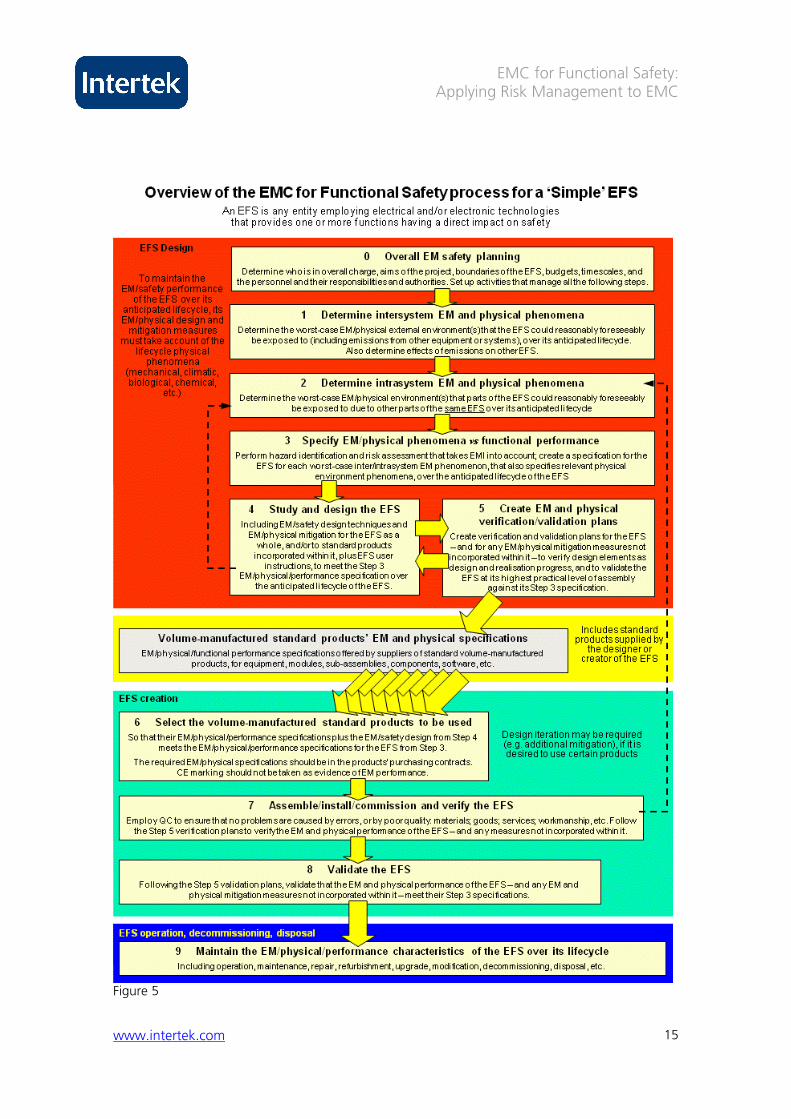
This approach has 10 basic steps, which are numbered from 0 to 9 in Figures 0.2 and 0.3 of this guide, see Figure 5. Step 0 in the guide is an overview of the problem, and a description of the overall risk management approach in sufficient
EMC for Functional Safety: Applying Risk Management to EMC
www.intertek.com 14
detail for it to be put into practice immediately by any competent manager, whereas Steps 1 through 9 describe practical measures and their documentation in sufficient detail for them to be put into practice immediately by any competent engineer. The guide also indicates how much detail and effort is required, depending on the level of risk that the EFS manufacturer is aiming for.
The IET guide [3] is a detailed practical implementation of [8], which has been written using the terminology of IEC 61508 [9] so that it can be used as its ‘missing EMC annex’. However, [3] has been written using terminology that allows it to be used whichever functional safety standard, or none, is employed on a project. This makes [3] useful, for example, for the medical industry under its ISO 14971, and for the automotive industry under its ISO 26262 (currently in draft).
Because the IET have very kindly made this guide freely available to all [3], the following description of its Steps is very brief.
Step 1: Determine lifetime intersystem EM, physical and climatic phenomena This Step results in a specification for the worst-case EM, physical and climatic external environments that the EFS could reasonably foreseeably be exposed to over its anticipated lifetime [27] [28]. It includes the emissions from equipment, systems or installations other than itself (see Step 2), and also considers the foreseeable effects of the emissions from the EFS, on the safety risks of other EFS.
The EM assessment of an EFS should include, but is not limited to, reasonably foreseeable:
• EM disturbances in the near-field (e.g. crosstalk in cable bundles) and far-field (e.g. radio/radar transmitters)
• Intra-system interference (between individual electronic units and cables within an EFS)
• Inter-system interference (between an EFS and the rest of the world; also considering electronic devices carried by people and their vehicles)
• Modulation types, and their frequencies or waveshapes • Physical environment(s) (e.g. mechanical, climatic, biological, wear, etc.) • Simultaneous EM and/or physical phenomena (including: continuous, extremes, cycling and transients)
• Faults and malfunctions (permanent or temporary) • Use and misuse • The effects of ageing • Future changes to the EM and physical environments • Component tolerances; future changes to components (e.g. obsolescence, die shrinks, etc.)
EMC for Functional Safety: Applying Risk Management to EMC
www.intertek.com 15
Figure 5
EMC for Functional Safety: Applying Risk Management to EMC
www.intertek.com 16
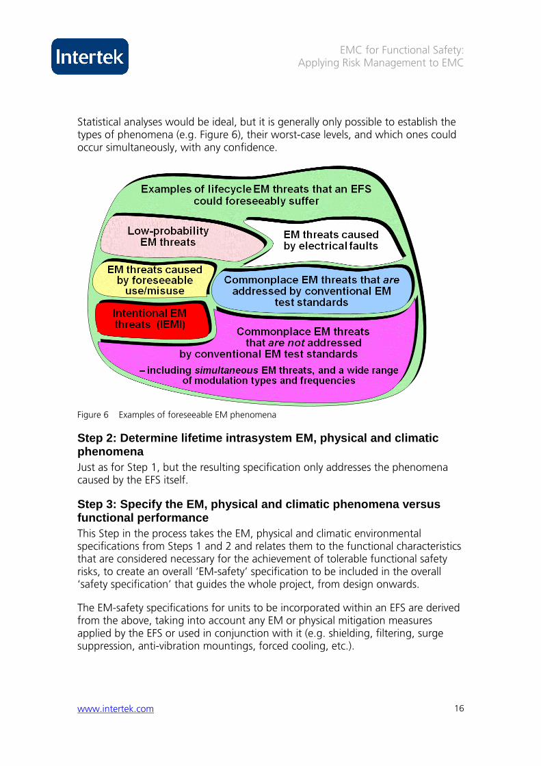
Statistical analyses would be ideal, but it is generally only possible to establish the types of phenomena (e.g. Figure 6), their worst-case levels, and which ones could occur simultaneously, with any confidence.
Figure 6 Examples of foreseeable EM phenomena
Step 2: Determine lifetime intrasystem EM, physical and climatic phenomena Just as for Step 1, but the resulting specification only addresses the phenomena caused by the EFS itself.
Step 3: Specify the EM, physical and climatic pheno mena versus functional performance This Step in the process takes the EM, physical and climatic environmental specifications from Steps 1 and 2 and relates them to the functional characteristics that are considered necessary for the achievement of tolerable functional safety risks, to create an overall ‘EM-safety’ specification to be included in the overall ‘safety specification’ that guides the whole project, from design onwards.
The EM-safety specifications for units to be incorporated within an EFS are derived from the above, taking into account any EM or physical mitigation measures applied by the EFS or used in conjunction with it (e.g. shielding, filtering, surge suppression, anti-vibration mountings, forced cooling, etc.).
EMC for Functional Safety: Applying Risk Management to EMC
www.intertek.com 17
Step 4: Study and design the EFS This employs a variety of EM and safety design [29] and mitigation techniques, and detailed risk assessment techniques, for example [30]. It also very usefully (and as far as the author is aware, for the first time ever) describes how to apply the standardized risk assessment methods to EMC issues.
Many EFS manufacturers already employ risk assessment methods, but they tend to do it ‘by rote’, which is not recommended by functional safety experts [31] [32] – and of course they do not apply these techniques to EMC – believing (incorrectly) that this is entirely dealt with by a programme of conventional EMC tests.
Step 4 of the guide [3] includes 26 pages detailing numerous well-proven EMC and physical/climatic engineering techniques that can be used, to help those who are not familiar with thinking in these terms get quickly up to speed.
Step 4 also includes a section describing common but incorrect assumptions in risk assessment, such as the idea that two or more independent malfunctions or faults are always so unlikely that only ‘single-fault’ issues need ever be considered.
Step 5: Create EM, physical and climatic verificati on and validation plans This Step results in detailed verification and validation plans for the EFS, to verify design elements as design and realisation progresses, and to validate the EFS at its highest practicable level of assembly against the specifications created by Step 3.
It should occur in parallel with Step 4, to enable very significant cost and time savings in verification and validation to be achieved by the use of appropriate design techniques.
Functional safety engineering employs a mixture of verification and validation techniques [33], none of which is sufficient on its own, including:
• Demonstrations • Checklists • Inspections • Reviews and Assessments • Independent reviews • Audits • Non-standardized checks and tests • Individual and/or integrated hardware tests • Validated computer modelling • EM, physical, climatic and highly-accelerated life testing (HALT) tests [34] • Quality control (QC)
EMC for Functional Safety: Applying Risk Management to EMC
www.intertek.com 18
Step 6: Selecting standard products or specifying c ustom hardware/software items for incorporation in the EF S Describes how to ensure that their EM, physical and climatic specifications, when combined with the design techniques used by Step 4, will help ensure that the EFS meets the EM-safety specifications from Step 3. Note that ‘CE marking’ should never be taken as evidence of any EM characteristics (the text in [3] explains why).
Step 7: Realise the EFS This includes its assembly, plus (where appropriate) its installation and commissioning, with the verification plans from Step 5 applied where necessary, and appropriate quality control to ensure that every aspect of the specified design (from Step 4) is achieved.
Step 8: Validating the EFS Following the Step 5 validation plans, this Step validates the EM, physical and climatic characteristics of the EFS against the EM-safety specifications from Step 3.
Step 9: Maintain the EM, physical and climatic char acteristics of the EFS over its lifetime This includes checking that any assumptions that were made in Steps 1 and 2, and taking appropriate actions if real-life turns out to be worse.
It also includes employing appropriate techniques in maintenance, repair, refurbishment, modification and upgrades (including software or firmware) to ensure that the EM, physical and climatic characteristics of the EFS are not degraded over its lifetime.
References
[1] IEC 61508-3: “Functional Safety of Electronic/Electronic/Programmable Electronic Safety-Related Systems – Part 3: Software Requirements”.
[2] D A Townsend et al, "Breaking All the Rules: Challenging the Engineering and Regulatory Precepts of Electromagnetic Compatibility", 1995 IEEE International EMC Symposium, Atlanta, pp 194 – 199.
[3] IET, “Guide on EMC for Functional Safety”, 2008, www.theiet.org/factfiles/emc/index.cfm
[4] Moore’s Law: visit http://www.intel.com/technology/mooreslaw/ and/or http://en.wikipedia.org/wiki/Moore's_law
[5] Keith Armstrong, “New Guidance on EMC-Related Functional Safety”, 2001 IEEE International EMC Symposium, Montreal, Aug. 13-17, ISBN 0-7803-6569-0/01, pp. 774-779.
EMC for Functional Safety: Applying Risk Management to EMC
www.intertek.com 19
[6] Keith Armstrong, “New Guidance on EMC and Safety for Machinery”, 2002 IEEE Int’l. EMC Symposium, Minneapolis, Aug. 19-23 2002, ISBN: 0-7803-7264-6, pp. 680-685.
[7] Keith Armstrong, “Review of Progress with EMC-Related Functional Safety”, 2003 IEEE EMC Symposium, Boston, Aug. 18-22 2003, ISBN 0-7803-7835-0, pp 454-460.
[8] IEC TS 61000-1-2, basic safety publication, draft second edition, 77/356/DTS February 2008, “Electromagnetic Compatibility (EMC) – Part 1-2: General – Methodology for the achievement of the functional safety of electrical and electronic equipment with regard to electromagnetic phenomena.”
[9] IEC 61508, basic safety publication, “Functional Safety of Electrical/Electronic/Programmable Electronic Safety-Related Systems” (seven parts).
[10] Keith Armstrong, “Why EMC Immunity Testing is Inadequate for Functional Safety”, 2004 IEEE Int’l EMC Symp., Santa Clara, Aug. 9-13 2004, ISBN 0-7803-8443-1, pp 145-149. Also: Conformity, March 2005, http://www.conformity.com/artman/publish/printer_227.shtml
[11] Keith Armstrong, “Functional Safety Requires Much More Than EMC Testing”, EMC-Europe 2004 (6th International Symposium on EMC), Eindhoven, The Netherlands, Sept. 6-10 2004, ISBN: 90-6144-990-1, pp 348-353.
[12] Keith Armstrong: “EMC in Safety Cases — Why EMC Testing is Never Enough”, EMC-UK 2007 Conference, Newbury, UK, Defence & Avionics session, October 17, 2007.
[13] L. Jansson and M. Bäckström, "Directivity of Equipment and its Effect on Testing in Mode-Stirred and Anechoic Chamber", IEEE Int’l EMC Symposium, Seattle, WA, Aug. 1999.
[14] G.J. Freyer, "Distribution of Responses for Limited Aspect Angle EME Tests of Equipment with Structured Directional Directivity", The 2003 Reverberation Chamber, Anechoic Chamber and OATS Users Meeting, Austin, TX, April 2003.
[15] G.J. Freyer and M.O. Hatfield, "An Introduction to Reverberation Chambers for Radiated Emission/Immunity Testing", ITEM 1998, www.interferencetechnology.com/ArchivedArtcles/shielded_rooms_and_enclosures/I98art15.htm?regid=
[16] G.J. Freyer, “Considerations for EMC Testing of Systems with Safety and/or Reliability Requirements”, EMC Europe 2004, Eindhoven, The Netherlands, Sept. 6-10 2004.
[17] S. Wendsche and E. Habiger, “Using reinforcement learning methods for effective EMC immunity testing of computerised equipment”, Proc. Int. Symp. EMC (ROMA’96), Rome, Italy, Sept 1996, pp.221-226.
[18] R. Vick and E. Habiger, “The dependence of the immunity of digital equipment on the hardware and software structure”, Proc. Int. Symp. EMC, Beijing, May 1997, pp 383-386.
[19] RTCA/DO-160F, “Environmental Conditions and Test Procedures for Airborne Equipment, Section 20, Radio Frequency Susceptibility (Radiated and Conducted)”, www.rtca.org.
[20] DaimlerChrysler Joint Engineering Standard DC-10614, “EM Performance Requirements --- Components”, 2004-01.
[21] “ICNIRP Statement on EMF-Emitting New Technologies”, G. Ziegelberger, published by the Health Physics Society, 94(4):376-392; 2008, 0017-9078/08/0, from: http://www.icnirp.de/PubEMF.htm
EMC for Functional Safety: Applying Risk Management to EMC
www.intertek.com 20
[22] Michel Mardiguian, “Combined Effects of Several, Simultaneous, EMI Couplings”, 2000 IEEE Int’l EMC Symp., Washington D.C., Aug 21-25, ISBN 0-7803-5680-2, pp. 181-184.
[23] MIL-STD-464, “Electromagnetic Environmental Effects – Requirements for Systems”, Department of Defense Interface Standard, March 18 1997.
[24] F Beck and J Sroka, “EMC Performance of Drive Application Under Real Load Condition”, Schaffner Application Note 11 March 1999; EMC Zurich, 2001; Power Quality, June 2001.
[25] Lena Sjögren and Mats Bäckström, “Ageing of Shielding Joints, Shielding Performance and Corrosion”, IEEE EMC Society Newsletter, Summer 2005, http://www.ieee.org/organizations/pubs/newsletters/emcs/summer05/practical.pdf
[26] John Terry, “The Design of Military Equipment Enclosures to Minimise the Effects of Corrosion”, EMC-UK 2005 Conference, Newbury, Oct 13-14, pp 85-88
[27] “Assessing an EM Environment”, Technical Guidance Note No. 47, EMC Test Labs Association (EMCTLA), www.emctla.co.uk/Pages/TechGuideMain_new.html
[28] Keith Armstrong, “Specifying Lifecycle Electromagnetic and Physical Environments – to Help Design and Test for EMC for Functional Safety”, 2005 IEEE Int’l EMC Symposium, Chicago, Aug. 8-12 2005, ISBN: 0-7803-9380-5, pp 495-499.
[29] Keith Armstrong, “Design and Mitigation Techniques for EMC for Functional Safety”, 2006 IEEE International EMC Symp., Portland, Aug. 14-18 2006, ISBN: 1-4244-0294-8.
[30] IEC 60300-3-1 “Dependability management – Part 3-1: Application guide – Analysis techniques for dependability – Guide on methodology”
[31] Erik Hollnagel, “The Reality of Risks”, Safety Critical Systems Club Newsletter, Vol. 17, No. 2, January 2008, pp 20-22, www.safety-club.org.uk
[32] Tim Kelly, “Are ‘Safety Cases’ Working?”, Safety Critical Systems Club Newsletter, Vol. 17, No. 2, January 2008, pp 31-33, www.safety-club.org.uk
[33] Keith Armstrong, “Validation, Verification and Immunity Testing Techniques for EMC for Functional Safety”, 2007 IEEE International EMC Symposium, July 9-13 2007, Honolulu, Hawaii, ISBN: 1-4244-1350-8
[34] W.H. Parker, W. Tustin, T. Masone, “The Case for Combining EMC and Environmental Testing”, ITEM 2002, pp 54-60, http://www.interferencetechnology.com/ArchivedArticles/test_instrumentation/i_02_10.pdf?regid=
[35] Keith Armstrong, “Why Increasing Immunity Test Levels is Not Sufficient for High-Reliability and Critical Equipment”, 2009 IEEE International EMC Symposium, Austin, TX, August 17-21, ISBN (CD-ROM): 978-1-4244-4285-0
For more information on specific testing and certification information, please contact Intertek at 1-800-WORLDLAB, email [email protected], or visit our website at www.intertek.com.
This publication is copyright Intertek and may not be reproduced or transmitted in any form in whole or in part without the prior written permission of Intertek. While due care has been taken during the preparation of this document, Intertek cannot be held responsible for the accuracy of the information herein or for any consequence arising from it. Clients are encouraged to seek Intertek’s current advice on their specific needs before acting upon any of the content.