Embed Size (px)
Citation preview

EMC CorporationCorporate Headquarters:
Hopkinton, MA 01748-9103
1-508-435-1000www.EMC.com
EMC® Ionix™
MPLS ManagerVersion 3.1
Discovery GuideP/N 300-010-227
REV A02

EMC Ionix MPLS Manager Version 3.1 Discovery Guide2
Copyright © 2004 - 2010 EMC Corporation. All rights reserved.
Published March, 2010
EMC believes the information in this publication is accurate as of its publication date. The information is subject to change without notice.
THE INFORMATION IN THIS PUBLICATION IS PROVIDED “AS IS.” EMC CORPORATION MAKES NO REPRESENTATIONS OR WARRANTIES OF ANY KIND WITH RESPECT TO THE INFORMATION IN THIS PUBLICATION, AND SPECIFICALLY DISCLAIMS IMPLIED WARRANTIES OF MERCHANTABILITY OR FITNESS FOR A PARTICULAR PURPOSE.
Use, copying, and distribution of any EMC software described in this publication requires an applicable software license.
For the most up-to-date listing of EMC product names, see EMC Corporation Trademarks on EMC.com.
All other trademarks used herein are the property of their respective owners.

EMC Ionix MPLS Manager Version 3.1 Discovery Guide 3
Preface
Chapter 1 Discovery Overview Terminology............................................................................................................. 16
System and device ............................................................................................ 16Discovery ........................................................................................................... 16Object.................................................................................................................. 16
LSP support ............................................................................................................. 17TE tunnels .......................................................................................................... 17TE LSPs .............................................................................................................. 17LDP LSPs ........................................................................................................... 17
VPN support............................................................................................................ 18MPLS L2VPNs................................................................................................... 18MPLS L3VPNs................................................................................................... 19
LDP adjacency and RSVP session support ......................................................... 19 Device support ........................................................................................................ 20 SNMP and CLI discovery support ....................................................................... 20 Overlapping IP address support .......................................................................... 22 VPN-Tagging Server support................................................................................ 22 Multi-VRF CE support ........................................................................................... 23
Client route advertisement.............................................................................. 23Single-homed or multi-homed configuration .............................................. 23
Discovery overview................................................................................................ 24 IP Availability Manager discovery....................................................................... 25 MPLS Topology Server discovery ........................................................................ 26
Imports topology from IP Availability Manager ......................................... 26Initiates discovery............................................................................................. 26Performs MPLS discovery............................................................................... 26Performs L2VPN discovery ............................................................................ 28Performs L3VPN discovery ............................................................................ 30Builds a complete model ................................................................................. 30Logs discovery messages................................................................................. 30Creates CLI log files ......................................................................................... 31
When discovery occurs .......................................................................................... 31
Contents
EMC Ionix MPLS Manager Version 3.1 Discovery Guide4
Contents
Chapter 2 MPLS VPN Overlapping IP Discovery Introducing the VPN-Tagging Server................................................................... 34
VPN-Tagging Server purpose ......................................................................... 34VPN-Tagging Server assistance ...................................................................... 35
Functional overview ............................................................................................... 36 Discovery in the Cisco environment .................................................................... 37 Discovery in the Alcatel-Lucent environment .................................................... 39
On-demand discovery...................................................................................... 41Adapter Configuration..................................................................................... 41
Discovery assumptions and criteria ..................................................................... 42 Overlapping IP naming format............................................................................. 42 Configuring the VPN-Tagging Server.................................................................. 43 Starting the VPN-Tagging Server.......................................................................... 43
Chapter 3 Discovery Process Discovery process overview .................................................................................. 46
Discovery types ................................................................................................. 46Summary of MPLS discovery.......................................................................... 46Summary of L2VPN discovery ....................................................................... 47Summary of L3VPN discovery ....................................................................... 47
Discovery process details ....................................................................................... 48Phase 1: Import initial topology...................................................................... 49Phase 2: Probe each managed device............................................................. 50Phase 3: Post-process the discovery information ......................................... 53
Chapter 4 Discovery of MPLS Objects MPLS discovery overview ..................................................................................... 56 More about LSPs and LSP discovery.................................................................... 57
TE tunnels and TE LSPs ................................................................................... 58LDP LSPs............................................................................................................ 60LSP discovery .................................................................................................... 60
More about LDP adjacencies and LDP adjacency discovery............................ 61 More about RSVP sessions and RSVP session discovery .................................. 62 MPLS discovery process......................................................................................... 63
SNMP and CLI discovery ................................................................................ 64Per-device discovery for MPLS....................................................................... 66Post-processing discovery for MPLS.............................................................. 71Relationships between the MPLS and transport models ............................ 76
Chapter 5 Discovery of L2VPN Objects L2VPN discovery overview................................................................................... 78 More about L2VPNs and L2VPN discovery ....................................................... 78
L2VPN encapsulation....................................................................................... 79Virtual Private Wire Service ............................................................................ 80Virtual Private LAN Service............................................................................ 81L2VPN discovery .............................................................................................. 82
More about targeted LDP adjacencies and LDP adjacency discovery ............ 84 L2VPN discovery process ...................................................................................... 85
SNMP and CLI discovery ................................................................................ 88Per-device discovery for L2VPN .................................................................... 88Post-processing discovery for L2VPN ........................................................... 90Relationships between the L2VPN, MPLS, and transport models ............ 95
EMC Ionix MPLS Manager Version 3.1 Discovery Guide 5
Contents
Chapter 6 Discovery of L3VPN Objects L3VPN discovery overview .................................................................................. 98 More about L3VPNs and L3VPN discovery....................................................... 98
L3VPN encapsulation ...................................................................................... 99L3VPN components ......................................................................................... 99L3VPN discovery............................................................................................ 100
L3VPN discovery process.................................................................................... 101SNMP and CLI discovery.............................................................................. 102Per-device discovery for L3VPN.................................................................. 102Post-processing discovery for L3VPN......................................................... 103Relationships between the L3VPN, MPLS, and transport models.......... 105
Chapter 7 Preparing and Initiating Discovery Preparing for discovery ....................................................................................... 108
Prepare the Global Manager for discovery................................................. 108Prepare IP Availability Manager for discovery ......................................... 108Prepare MPLS Manager for discovery ........................................................ 109
Initiating discovery............................................................................................... 109 Synchronizing with IP Availability Manager ................................................... 110
Topology synchronization ............................................................................ 110CLI device-access object synchronization................................................... 110
Synchronizing with the MPLS Topology Server ............................................... 111MPLS Monitoring Server synchronization ................................................. 111MPLS Analysis Server synchronization ...................................................... 112Imported topology subsets............................................................................ 113Other synchronizations for the MPLS Monitoring Server........................ 114
Specifying a different IP Availability Manager source.................................... 114Procedure for specifying a different IP Availability Manager source .... 115
Chapter 8 Understanding Discovery Results Discovery results................................................................................................... 118
Successful discovery....................................................................................... 118Unsuccessful discovery ................................................................................. 118
Discovery error resolutions ................................................................................. 119Open the Domain Manager Administration Console ............................... 119Check the Discovery Progress window ...................................................... 121Check the server log files............................................................................... 122Check the CLI log files ................................................................................... 122
Error message formatting .................................................................................... 122 Examples of error messages in CLI log files ..................................................... 124 Pending Elements list........................................................................................... 125
Information provided by the Pending Elements list ................................. 126Management of individual pending element entries................................ 126
Chapter 9 Invoking Full or Pending Discovery Discovery methods ............................................................................................... 128 Full discovery ........................................................................................................ 128
Automatic full discovery............................................................................... 128Manual full discovery .................................................................................... 128
Pending discovery ................................................................................................ 129Automatic pending discovery ...................................................................... 129Manual pending discovery ........................................................................... 130

EMC Ionix MPLS Manager Version 3.1 Discovery Guide6
Contents
Appendix A MIBs Accessed for Discovery and Remote Ping SNMP versions supported................................................................................... 132 MIBs accessed for MPLS discovery .................................................................... 132 MIBs accessed for L2VPN discovery.................................................................. 135 MIBs accessed for L3VPN discovery.................................................................. 137 MIBs accessed for remote ping............................................................................ 138
Appendix B CLI Commands Invoked for Discovery and LSP Ping CLI commands overview..................................................................................... 140 CLI commands invoked on Cisco devices......................................................... 140 CLI commands invoked on Huawei devices .................................................... 142 CLI commands invoked on Juniper M/T devices............................................ 143 CLI commands invoked on Juniper ERX devices ............................................ 144 CLI commands invoked for LSP ping................................................................ 146
Index
EMC Ionix MPLS Manager Version 3.1 Discovery Guide 7
Title Page
1 MPLS VPN implementations .............................................................................................. 182 LDP adjacencies and RSVP sessions ................................................................................... 193 A multi-VRF CE device deployment serving five clients ............................................... 234 MPLS Manager discovery .................................................................................................... 245 Physical-transport domain discovered by IP Availability Manager ............................. 256 MPLS domain discovered by the MPLS Topology Server .............................................. 267 Network recovery through link protection ....................................................................... 278 Network recovery through node protection ..................................................................... 279 Network recovery through path protection ...................................................................... 2810 VPWS L2VPN domain discovered by the MPLS Topology Server ............................... 2911 VPLS L2VPN domain discovered by the MPLS Topology Server ................................. 2912 L3VPN domain discovered by the MPLS Topology Server ........................................... 3013 Example of overlapping IPs in MPLS-enabled VPNs ...................................................... 3414 IP overlapping configuration 1: separate PE-CE pairs .................................................... 3515 IP overlapping configuration 2: common PE, separate CEs ........................................... 3516 IP overlapping configuration 3: common PE and CE, separate VRFs ........................... 3617 VPN-Tagging Server discovery in the Cisco environment ............................................. 3718 MPLS VPN overlapping IP discovery flow in the Cisco environment ......................... 3819 VPN-Tagging Server discovery in the Alcatel-Lucent environment ............................. 3920 Discovery flow for the MPLS Topology Server ................................................................ 4821 MPLS encapsulation and transport .................................................................................... 5722 FRR switching for a failed link ............................................................................................ 5823 FRR switching for a failed node .......................................................................................... 5924 Path-protection switching for a failed TE tunnel ............................................................. 6025 Non-targeted LDP adjacencies ............................................................................................ 6126 RSVP session .......................................................................................................................... 6227 Simplified view of LSP modeling in MPLS data model .................................................. 6328 Simplified view of non-targeted LDP adjacency modeling in MPLS data model ....... 6329 Simplified view of RSVP session modeling in MPLS data model ................................. 6430 The LSP table manager and LSP discovery ....................................................................... 6831 Two LSP segment entries of an LSP ................................................................................... 6932 Relationships for the link/node and path-protected TE tunnel examples ................... 7333 Relationships between the MPLS and transport models ................................................ 7634 MPLS L2VPN encapsulation and transport ...................................................................... 7935 Using VPWS to connect customer sites over an MPLS network .................................... 8036 Using VPLS to connect customer sites over an MPLS network ..................................... 8137 Discovering a VPWS instance that is configured with LSP protection ......................... 8338 Targeted LDP adjacency ...................................................................................................... 8439 Simplified view of LDP-signaled L2VPN data model ..................................................... 8540 Simplified view of BGP-signaled L2VPN data model ..................................................... 86
Figures
EMC Ionix MPLS Manager Version 3.1 Discovery Guide8
Figures
41 Simplified view of VLAN modeling in the L2VPN data model ..................................... 8742 LayeredOver algorithm for ForwarderEndpoints and LSPs ........................................... 9443 Relationships between the LDP-signaled L2VPN, MPLS, and transport models ....... 9544 Relationships between the BGP-signaled L2VPN, MPLS, and transport models ........ 9645 MPLS L3VPN encapsulation and transport ...................................................................... 9946 Using L3VPNs to connect customer sites over an MPLS network ............................... 10047 Simplified view of L3VPN data model ............................................................................ 10148 LayeredOver algorithm for VRFs and LSPs .................................................................... 10449 Relationships between the L3VPN, MPLS, and transport models ............................... 10550 Topology subsets imported by the MPLS Monitoring and Analysis Servers ............ 11351 Attach Manager dialog box ................................................................................................ 12052 Domain Manager Administration Console ..................................................................... 12153 EMC Ionix exception message formatting ....................................................................... 12254 Pending Elements list containing one pending element ................................................ 125
EMC Ionix MPLS Manager Version 3.1 Discovery Guide 9
Title Page
1 Discovery sources for supported devices .......................................................................... 202 Initial topology added to the MPLS Topology Server repository .................................. 503 Additional topology added to the MPLS Topology Server repository ......................... 544 Discovery sources for MPLS TE tunnels and LSPs .......................................................... 655 Discovery sources for MPLS LDP adjacencies and RSVP sessions ................................ 656 Device type definitions ......................................................................................................... 667 MPLSService relationship set .............................................................................................. 678 Discovery sources for MPLS LDP- and BGP-signaled L2VPNs ..................................... 889 Discovery sources for MPLS L3VPNs .............................................................................. 10210 Some EMC Ionix subsystems and their descriptions ..................................................... 12311 MIB objects accessed for MPLS discovery ....................................................................... 13212 MIB objects accessed for L2VPN discovery .................................................................... 13513 MIB objects accessed for L3VPN discovery .................................................................... 13714 MIBs access for remote ping .............................................................................................. 13815 CLI commands for discovery on Cisco devices .............................................................. 14016 CLI commands for discovery on Huawei devices ......................................................... 14217 CLI commands for discovery on Juniper M/T devices ................................................. 14318 CLI commands for discovery on Juniper ERX devices .................................................. 144
Tables

EMC Ionix MPLS Manager Version 3.1 Discovery Guide10
Tables
EMC Ionix MPLS Manager Version 3.1 Discovery Guide 11
Preface
As part of an effort to improve and enhance the performance and capabilities of its product lines, EMC periodically releases revisions of its hardware and software. Therefore, some functions described in this document might not be supported by all versions of the software or hardware currently in use. For the most up-to-date information on product features, refer to your product release notes.
If a product does not function properly or does not function as described in this document, please contact your EMC representative.
Audience This document is part of the EMC Ionix MPLS Management Suite documentation set. It is intended for IT managers seeking to understand how the MPLS Manager discovery process works, and for system administrators responsible for the administration, configuration, or use of MPLS Manager.
EMC Ionix MPLSManagement Suite
installation directory
In this document, the term BASEDIR represents the location where EMC Ionix software is installed:
◆ For UNIX, this location is: /opt/InCharge<n>/<productsuite>.
◆ For Windows, this location is: C:\InCharge<n>\<productsuite>.
The <n> represents the EMC Ionix software platform version number. The <productsuite> represents the EMC Ionix product suite to which the product belongs. For example, on UNIX operating systems, EMC Ionix MPLS Management Suite is, by default, installed to /opt/InCharge7/MPLS/smarts. On Windows operating systems, this product is, by default, installed to C:\InCharge7\MPLS\smarts. This location is referred to as BASEDIR/smarts.
Optionally, you can specify the root of BASEDIR to be something other than /opt/InCharge7 (on UNIX) or C:\InCharge7 (on Windows), but you cannot change the <productsuite> location under the root directory.
The EMC Smarts System Administration Guide provides detailed information about the directory structure for EMC Ionix software.
EMC Ionix MPLSManagement Suite
products
The EMC Ionix MPLS Management Suite includes the following products:
◆ EMC Ionix MPLS Manager
◆ EMC Ionix Adapter for Cisco ISC
◆ EMC Ionix VPN-Tagging Server
EMC Ionix MPLS Manager Version 3.1 Discovery Guide12
Preface
Relateddocumentation
In addition to this document, EMC Corporation provides a Help system for command line programs as well as product documentation.
Help for command line programsDescriptions of command line programs are available as HTML pages. The index.html file, which provides an index to the various commands, is located in the BASEDIR/smarts/doc/html/usage directory.
EMC Ionix documentationReaders of this guide might find the following related documentation helpful. The documents can be found in the BASEDIR/smarts/doc/pdf directory:
Note: These documents are updated periodically. Electronic versions of the updated manuals are available on the Powerlink website:http://Powerlink.EMC.com
◆ EMC Smarts Documentation Catalog
◆ EMC Smarts System Administration Guide
◆ EMC Smarts ICIM Reference
◆ EMC Smarts Common Information Model Infrastructure Models Chart
◆ EMC Smarts Common Information Model Application/Business Models Chart
◆ EMC Smarts ASL Reference Guide
◆ EMC Smarts Perl Reference Guide
◆ EMC Smarts MODEL Reference Guide
EMC Ionix MPLS Management Suite documentationThe following documents are relevant to users of the EMC Ionix MPLS Management Suite:
◆ EMC Ionix MPLS Management Suite Release Notes (Powerlink only)
◆ EMC Ionix MPLS Management Suite Installation Guide
◆ EMC Ionix MPLS Management Suite Third-Party Copyright Read Me
◆ EMC Ionix MPLS Manager Configuration Guide
◆ EMC Ionix MPLS Manager Discovery Guide
◆ EMC Ionix MPLS Manager User Guide
◆ EMC Ionix Adapter for Cisco ISC User Guide
◆ EMC Ionix MPLS Certification Matrix (Powerlink only)
Suggestions forsearching PDF files
You can search across multiple PDF files by using the Adobe Acrobat Reader software:
1. If the documentation is not accessible to all users of the EMC Ionix product suite, copy the contents of the BASEDIR/smarts/doc/pdf directory to a central location, such as a shared drive on your LAN, so that operators and others can view the documentation.
2. To search throughout the documentation library, open the Acrobat Reader software:
a. Select Edit > Search, and type a word or phrase.
b. Select All PDF Documents in, in the Where would you like to search option, and type the pathname of the location where the PDF documents reside.

EMC Ionix MPLS Manager Version 3.1 Discovery Guide 13
Preface
If you have more than one EMC Ionix product suite installed, you can set up cross-product document searches by copying files from the BASEDIR/smarts/doc/pdf directory for each product suite into this common documentation directory path.
Conventions used inthis document
EMC uses the following conventions for special notices.
Note: A note presents information that is important, but not hazard-related.
CAUTION!A caution contains information essential to avoid data loss or damage to the system or equipment.
IMPORTANT!An important notice contains information essential to software or hardware operation.
Typographical conventionsEMC uses the following type style conventions in this document:
Normal Used in running (nonprocedural) text for:• Names of interface elements (such as names of windows, dialog boxes, buttons,
fields, and menus)• Names of resources, attributes, pools, Boolean expressions, buttons, DQL
statements, keywords, clauses, environment variables, functions, utilities• URLs, pathnames, filenames, directory names, computer names, filenames, links,
groups, service keys, file systems, notifications
Bold Used in procedures for:• Names of interface elements (such as names of windows, dialog boxes, buttons,
fields, and menus)• What user specifically selects, clicks, presses, or types
Italic Used in text for:• Full titles of publications referenced in text• Emphasis (for example a new term)
Courier Used for:• System output, such as an error message or script• URLs, complete paths, filenames, prompts, and syntax when shown outside of
running text
Courier bold Used for:• Specific user input (such as commands)
Courier italic Used in procedures for:• Variables on command line• User input variables
< > Angle brackets enclose parameter or variable values supplied by the user
[ ] Square brackets enclose optional values
| Vertical bar indicates alternate selections - the bar means “or”
{ } Braces indicate content that you must specify (that is, x or y or z)
... Ellipses indicate nonessential information omitted from the example

EMC Ionix MPLS Manager Version 3.1 Discovery Guide14
Preface
Pathname conventionsDirectory pathnames are shown with forward slashes (/). Users of the Windows operating systems should substitute back slashes (\) for forward slashes.
Graphical conventionsThe figures that illustrate consoles represent the consoles as they appear in Windows. Under UNIX, the consoles appear with slight differences. For example, in views that display items in a tree hierarchy such as the Topology Browser, a plus sign appears for Windows, and an open circle appears for UNIX.
ManagerUnless otherwise specified, the term Manager is used to refer to EMC Ionix programs such as Domain Managers, Global Managers, and adapters.
Where to get help EMC support, product, and licensing information can be obtained as follows.
Product information — For documentation, release notes, software updates, or for information about EMC products, licensing, and service, go to the EMC Powerlink website (registration required) at:
http://Powerlink.EMC.com
Technical support — For technical support, go to Powerlink and choose Support. On the Support page, you will see several options, including one for making a service request. Note that to open a service request, you must have a valid support agreement. Please contact your EMC sales representative for details about obtaining a valid support agreement or with questions about your account.
Your comments Your suggestions will help us continue to improve the accuracy, organization, and overall quality of the user publications. Please send your opinion of this document to:
If you have issues, comments, or questions about specific information or procedures, please include the title and, if available, the part number, the revision (for example, A01), the page numbers, and any other details that will help us locate the subject you are addressing.
Discovery Overview 15
1
This chapter introduces EMC Ionix MPLS Manager and describes the concepts of using MPLS Manager to discover MPLS and VPN topology. It consists of the following sections:
◆ Terminology .................................................................................................................... 16◆ LSP support..................................................................................................................... 17◆ VPN support ................................................................................................................... 18◆ LDP adjacency and RSVP session support................................................................. 19◆ Device support................................................................................................................ 20◆ SNMP and CLI discovery support .............................................................................. 20◆ Overlapping IP address support.................................................................................. 22◆ VPN-Tagging Server support ....................................................................................... 22◆ Multi-VRF CE support .................................................................................................. 23◆ Discovery overview ....................................................................................................... 24◆ IP Availability Manager discovery .............................................................................. 25◆ MPLS Topology Server discovery................................................................................ 26◆ When discovery occurs ................................................................................................. 31
Discovery Overview
EMC Ionix MPLS Manager Version 3.1 Discovery Guide16
Discovery Overview
TerminologyEMC® Ionix™ MPLS Manager is an EMC Ionix Domain Manager. A Domain Manager is a service-assurance application that is associated with a particular type of information-technology domain, such as networks, systems, applications, or application services. For MPLS Manager, the domain is the Multiprotocol Label Switching (MPLS) network and the MPLS virtual private network (VPN). Each Domain Manager is autonomous in the sense that it:
◆ Maintains its own data models, repository, and problem signatures.
◆ Monitors and analyzes the discovered objects in its own domain.
System and deviceThe term “system” is a generic term that represents a computer-based network entity, such as a host, router, or switch. The term “device” has essentially the same meaning as system except that, in some cases, “device” also conveys the sense of specific model, such as a specific model of host, router, or switch.
DiscoveryEMC Ionix discovery is the process of using EMC Ionix object class models to create a representation of the managed topology within the repository, or database, of a Domain Manager. For MPLS Manager, data is collected from MPLS-enabled devices in the managed network to create instances of MPLS and VPN topology objects, their relationships, and their logical connections.
When an MPLS-enabled device is added to the managed network, MPLS Manager performs discovery on the device to determine the MPLS and VPN topology objects that are associated with the device. When an MPLS-enabled device is removed from the managed network and deleted from the topology, MPLS Manager removes the device and all the device’s associated MPLS and VPN topology objects from the modeled topology.
ObjectThe term “object” is intended to have a dual meaning: To simultaneously represent both (1) an EMC Ionix object in the modeled topology and (2) a physical or logical entity in the real topology. An EMC Ionix object corresponds to a physical or logical entity in the real topology.
LSP support 17
Discovery Overview
LSP supportMPLS Manager is able to discover traffic engineering (TE) tunnels and the following types of label switched paths (LSPs):
◆ TE LSPs
◆ Label Distribution Protocol (LDP) LSPs
An LSP is a sequence of switch hops that together form a path that is traversed by labeled packets across an MPLS network.
TE tunnelsTE tunnels are virtual paths between headend and tailend routing devices in an MPLS network. The routing devices may be Provider Edge (PE) or Provider (P) devices. A TE tunnel is associated with one or more TE LSPs.
MPLS Manager is able to discover the following types of TE tunnels:
◆ Link- and node-protected TE tunnels
MPLS Manager discovers the primary and backup TE LSPs for TE tunnels that have been configured for link and node protection.
◆ Path-protected TE tunnels
MPLS Manager discovers the primary and secondary TE LSPs for TE tunnels that have been configured for path protection.
TE LSPsAlso known as tunnel LSPs, TE LSPs are constrained paths that are constructed by a signaling protocol such as Resource Reservation Protocol with TE extensions (RSVP-TE). RSVP-TE distributes and assigns labels, manages quality of service (QoS) issues, and handles error conditions.
LDP LSPsAlso known as generic LSPs, LDP LSPs are paths that are constructed by standard routing protocols and the Label Distribution Protocol. LDP is an MPLS signaling protocol that distributes and assigns labels within an MPLS network.
The standard routing protocols and LDP consider only the shortest path across the network when building LSPs. They do not take into account any constraints such as QoS or LSP protection.
EMC Ionix MPLS Manager Version 3.1 Discovery Guide18
Discovery Overview
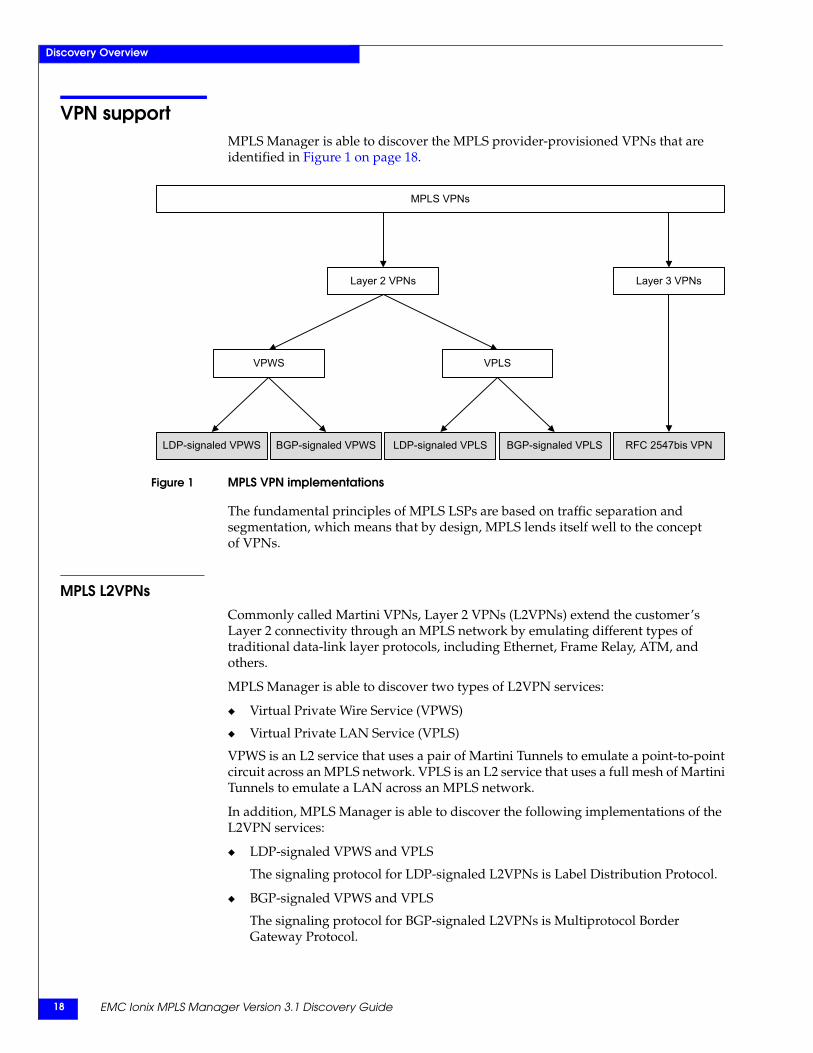
VPN supportMPLS Manager is able to discover the MPLS provider-provisioned VPNs that are identified in Figure 1 on page 18.
Figure 1 MPLS VPN implementations
The fundamental principles of MPLS LSPs are based on traffic separation and segmentation, which means that by design, MPLS lends itself well to the concept of VPNs.
MPLS L2VPNsCommonly called Martini VPNs, Layer 2 VPNs (L2VPNs) extend the customer’s Layer 2 connectivity through an MPLS network by emulating different types of traditional data-link layer protocols, including Ethernet, Frame Relay, ATM, and others.
MPLS Manager is able to discover two types of L2VPN services:
◆ Virtual Private Wire Service (VPWS)
◆ Virtual Private LAN Service (VPLS)
VPWS is an L2 service that uses a pair of Martini Tunnels to emulate a point-to-point circuit across an MPLS network. VPLS is an L2 service that uses a full mesh of Martini Tunnels to emulate a LAN across an MPLS network.
In addition, MPLS Manager is able to discover the following implementations of the L2VPN services:
◆ LDP-signaled VPWS and VPLS
The signaling protocol for LDP-signaled L2VPNs is Label Distribution Protocol.
◆ BGP-signaled VPWS and VPLS
The signaling protocol for BGP-signaled L2VPNs is Multiprotocol Border Gateway Protocol.
MPLS VPNs
VPWS VPLS
Layer 2 VPNs Layer 3 VPNs
RFC 2547bis VPNLDP-signaled VPWS BGP-signaled VPWS LDP-signaled VPLS BGP-signaled VPLS
LDP adjacency and RSVP session support 19
Discovery Overview
MPLS Manager requires a Level 2 VPN feature license for the discovery of VPWS and VPLS L2 services. The EMC Smarts System Administration Guide provides information about licensing.
MPLS L3VPNsDefined by IETF RFC-2547bis, Layer 3 VPNs (L3VPNs) use extensions to the existing Internet routing protocol BGPv4 to interconnect remote customer sites through an MPLS network. L3VPN is a virtual private routed network solution for IP data traffic only.
Central to an L3VPN is the VPN routing and forwarding (VRF) table, which allows for separate and private VPN forwarding decisions to co-exist within a PE device. The VRF is the fundamental mechanism that enables the partitioning of individual customers over the shared IP routed infrastructure.
MPLS Manager requires a Level 3 VPN feature license for the discovery of L3VPNs. The EMC Smarts System Administration Guide provides information about licensing.
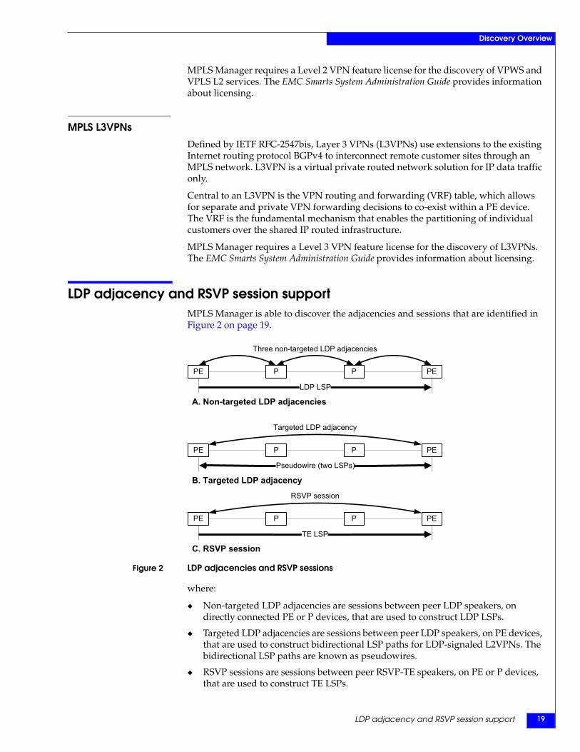
LDP adjacency and RSVP session supportMPLS Manager is able to discover the adjacencies and sessions that are identified in Figure 2 on page 19.
Figure 2 LDP adjacencies and RSVP sessions
where:
◆ Non-targeted LDP adjacencies are sessions between peer LDP speakers, on directly connected PE or P devices, that are used to construct LDP LSPs.
◆ Targeted LDP adjacencies are sessions between peer LDP speakers, on PE devices, that are used to construct bidirectional LSP paths for LDP-signaled L2VPNs. The bidirectional LSP paths are known as pseudowires.
◆ RSVP sessions are sessions between peer RSVP-TE speakers, on PE or P devices, that are used to construct TE LSPs.
PE PEP P
C. RSVP session
TE LSP
PE PEP P
A. Non-targeted LDP adjacencies
LDP LSP
Three non-targeted LDP adjacencies
PE PEP P
B. Targeted LDP adjacency
Pseudowire (two LSPs)
Targeted LDP adjacency
RSVP session
EMC Ionix MPLS Manager Version 3.1 Discovery Guide20
Discovery Overview
Device supportMPLS Manager supports the discovery, monitoring, and analysis of MPLS networks in any of the following vendor-specific environments:
◆ Cisco
◆ Huawei
◆ Juniper
The EMC Ionix MPLS Certification Matrix identifies the Cisco, Huawei, and Juniper devices that have been fully tested for this release of MPLS Manager. This document is found on Powerlink at http://Powerlink.EMC.com.
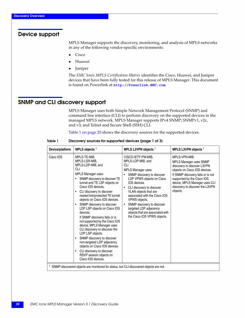
SNMP and CLI discovery supportMPLS Manager uses both Simple Network Management Protocol (SNMP) and command line interface (CLI) to perform discovery on the supported devices in the managed MPLS network. MPLS Manager supports IPv4 SNMP; SNMPv1, v2c, and v3; and Telnet and Secure Shell (SSH) CLI.
Table 1 on page 20 shows the discovery sources for the supported devices.
Table 1 Discovery sources for supported devices (page 1 of 3)
Device/platform MPLS objects 1 MPLS L2VPN objects 1 MPLS L3VPN objects 1
Cisco IOS MPLS-TE-MIB, MPLS-LSR-MIB, MPLS-LDP-MIB, and CLIMPLS Manager uses:• SNMP discovery to discover TE
tunnel and TE LSP objects on Cisco IOS devices.
• CLI discovery to discover nested link/protected TE tunnel objects on Cisco IOS devices.
• SNMP discovery to discover LDP LSP objects on Cisco IOS devices.If SNMP discovery fails or is not supported by the Cisco IOS device, MPLS Manager uses CLI discovery to discover the LDP LSP objects.
• SNMP discovery to discover non-targeted LDP adjacency objects on Cisco IOS devices.
• CLI discovery to discover RSVP session objects on Cisco IOS devices.
CISCO-IETF-PW-MIB, MPLS-LDP-MIB, and CLIMPLS Manager uses:• SNMP discovery to discover
LDP VPWS objects on Cisco IOS devices.
• CLI discovery to discover VLAN objects that are associated with the Cisco IOS VPWS objects.
• SNMP discovery to discover targeted LDP adjacency objects that are associated with the Cisco IOS VPWS objects.
MPLS-VPN-MIBMPLS Manager uses SNMP discovery to discover L3VPN objects on Cisco IOS devices.If SNMP discovery fails or is not supported by the Cisco IOS device, MPLS Manager uses CLI discovery to discover the L3VPN objects.
1 SNMP-discovered objects are monitored for status, but CLI-discovered objects are not.
SNMP and CLI discovery support 21
Discovery Overview
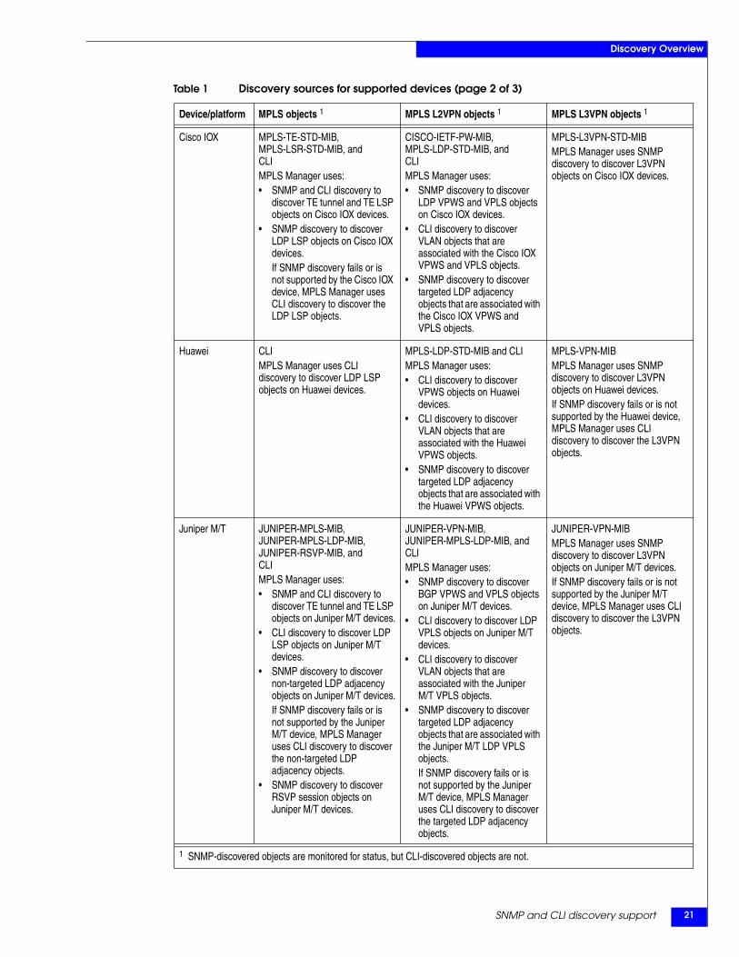
Cisco IOX MPLS-TE-STD-MIB, MPLS-LSR-STD-MIB, and CLIMPLS Manager uses:• SNMP and CLI discovery to
discover TE tunnel and TE LSP objects on Cisco IOX devices.
• SNMP discovery to discover LDP LSP objects on Cisco IOX devices.If SNMP discovery fails or is not supported by the Cisco IOX device, MPLS Manager uses CLI discovery to discover the LDP LSP objects.
CISCO-IETF-PW-MIB, MPLS-LDP-STD-MIB, and CLIMPLS Manager uses:• SNMP discovery to discover
LDP VPWS and VPLS objects on Cisco IOX devices.
• CLI discovery to discover VLAN objects that are associated with the Cisco IOX VPWS and VPLS objects.
• SNMP discovery to discover targeted LDP adjacency objects that are associated with the Cisco IOX VPWS and VPLS objects.
MPLS-L3VPN-STD-MIBMPLS Manager uses SNMP discovery to discover L3VPN objects on Cisco IOX devices.
Huawei CLIMPLS Manager uses CLI discovery to discover LDP LSP objects on Huawei devices.
MPLS-LDP-STD-MIB and CLIMPLS Manager uses:• CLI discovery to discover
VPWS objects on Huawei devices.
• CLI discovery to discover VLAN objects that are associated with the Huawei VPWS objects.
• SNMP discovery to discover targeted LDP adjacency objects that are associated with the Huawei VPWS objects.
MPLS-VPN-MIBMPLS Manager uses SNMP discovery to discover L3VPN objects on Huawei devices.If SNMP discovery fails or is not supported by the Huawei device, MPLS Manager uses CLI discovery to discover the L3VPN objects.
Juniper M/T JUNIPER-MPLS-MIB, JUNIPER-MPLS-LDP-MIB, JUNIPER-RSVP-MIB, and CLIMPLS Manager uses:• SNMP and CLI discovery to
discover TE tunnel and TE LSP objects on Juniper M/T devices.
• CLI discovery to discover LDP LSP objects on Juniper M/T devices.
• SNMP discovery to discover non-targeted LDP adjacency objects on Juniper M/T devices.If SNMP discovery fails or is not supported by the Juniper M/T device, MPLS Manager uses CLI discovery to discover the non-targeted LDP adjacency objects.
• SNMP discovery to discover RSVP session objects on Juniper M/T devices.
JUNIPER-VPN-MIB, JUNIPER-MPLS-LDP-MIB, and CLIMPLS Manager uses:• SNMP discovery to discover
BGP VPWS and VPLS objects on Juniper M/T devices.
• CLI discovery to discover LDP VPLS objects on Juniper M/T devices.
• CLI discovery to discover VLAN objects that are associated with the Juniper M/T VPLS objects.
• SNMP discovery to discover targeted LDP adjacency objects that are associated with the Juniper M/T LDP VPLS objects.If SNMP discovery fails or is not supported by the Juniper M/T device, MPLS Manager uses CLI discovery to discover the targeted LDP adjacency objects.
JUNIPER-VPN-MIBMPLS Manager uses SNMP discovery to discover L3VPN objects on Juniper M/T devices.If SNMP discovery fails or is not supported by the Juniper M/T device, MPLS Manager uses CLI discovery to discover the L3VPN objects.
Table 1 Discovery sources for supported devices (page 2 of 3)
Device/platform MPLS objects 1 MPLS L2VPN objects 1 MPLS L3VPN objects 1
1 SNMP-discovered objects are monitored for status, but CLI-discovered objects are not.
EMC Ionix MPLS Manager Version 3.1 Discovery Guide22
Discovery Overview
Overlapping IP address supportMPLS Manager supports (understands) VRF IP objects and IPNetwork objects that have been tagged by IP Availability Manager.
Tagged IP and IPNetwork objects enable IP Availability Manager to discover overlapping IP addresses and store them in its modeled topology. By importing tagged IP and IPNetwork objects from IP Availability Manager, MPLS Manager is able to store overlapping IP addresses in its modeled topology.
The inclusion of overlapping IP addresses in the modeled topology results in a more accurate and more complete model of the topology, which enables IP Availability Manager and MPLS Manager to perform more accurate correlation analysis.
By default, IP Availability Manager is not enabled to perform discovery of overlapping IP addresses. The EMC Ionix MPLS Manager Configuration Guide provides instructions for enabling this feature.
VPN-Tagging Server supportThe VPN-Tagging Server assists IP Availability Manager in the creation of certain overlapping IP-address configurations. Chapter 2, ”MPLS VPN Overlapping IP Discovery,” provides information about how the VPN-Tagging Server accomplishes this task.
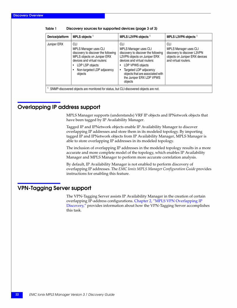
Juniper ERX CLIMPLS Manager uses CLI discovery to discover the following MPLS objects on Juniper ERX devices and virtual routers:• LDP LSP objects• Non-targeted LDP adjacency
objects
CLIMPLS Manager uses CLI discovery to discover the following L2VPN objects on Juniper ERX devices and virtual routers:• LDP VPWS objects• Targeted LDP adjacency
objects that are associated with the Juniper ERX LDP VPWS objects
CLIMPLS Manager uses CLI discovery to discover L3VPN objects on Juniper ERX devices and virtual routers.
Table 1 Discovery sources for supported devices (page 3 of 3)
Device/platform MPLS objects 1 MPLS L2VPN objects 1 MPLS L3VPN objects 1
1 SNMP-discovered objects are monitored for status, but CLI-discovered objects are not.
Multi-VRF CE support 23
Discovery Overview
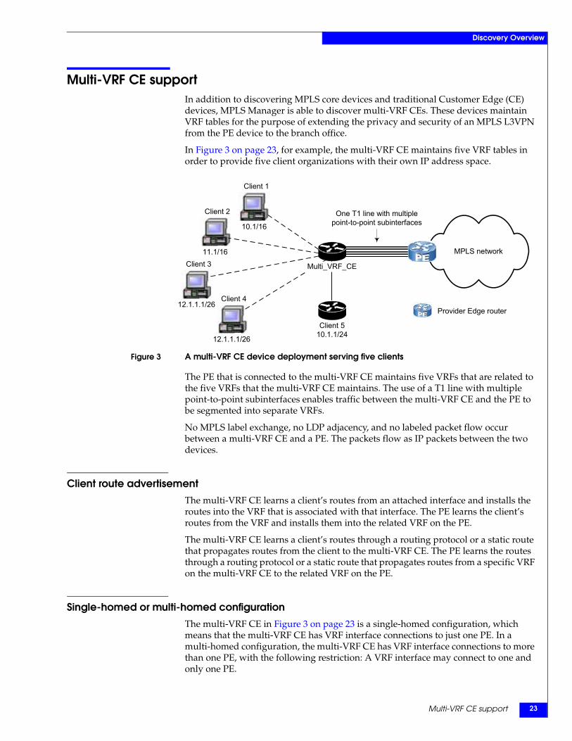
Multi-VRF CE supportIn addition to discovering MPLS core devices and traditional Customer Edge (CE) devices, MPLS Manager is able to discover multi-VRF CEs. These devices maintain VRF tables for the purpose of extending the privacy and security of an MPLS L3VPN from the PE device to the branch office.
In Figure 3 on page 23, for example, the multi-VRF CE maintains five VRF tables in order to provide five client organizations with their own IP address space.
Figure 3 A multi-VRF CE device deployment serving five clients
The PE that is connected to the multi-VRF CE maintains five VRFs that are related to the five VRFs that the multi-VRF CE maintains. The use of a T1 line with multiple point-to-point subinterfaces enables traffic between the multi-VRF CE and the PE to be segmented into separate VRFs.
No MPLS label exchange, no LDP adjacency, and no labeled packet flow occur between a multi-VRF CE and a PE. The packets flow as IP packets between the two devices.
Client route advertisementThe multi-VRF CE learns a client’s routes from an attached interface and installs the routes into the VRF that is associated with that interface. The PE learns the client’s routes from the VRF and installs them into the related VRF on the PE.
The multi-VRF CE learns a client’s routes through a routing protocol or a static route that propagates routes from the client to the multi-VRF CE. The PE learns the routes through a routing protocol or a static route that propagates routes from a specific VRF on the multi-VRF CE to the related VRF on the PE.
Single-homed or multi-homed configurationThe multi-VRF CE in Figure 3 on page 23 is a single-homed configuration, which means that the multi-VRF CE has VRF interface connections to just one PE. In a multi-homed configuration, the multi-VRF CE has VRF interface connections to more than one PE, with the following restriction: A VRF interface may connect to one and only one PE.
MPLS network
Client 510.1.1/24
Client 3
12.1.1.1/26
Client 2
11.1/16
Client 1
10.1/16
One T1 line with multiple point-to-point subinterfaces
Multi_VRF_CE
Client 4
12.1.1.1/26
Provider Edge router
EMC Ionix MPLS Manager Version 3.1 Discovery Guide24
Discovery Overview
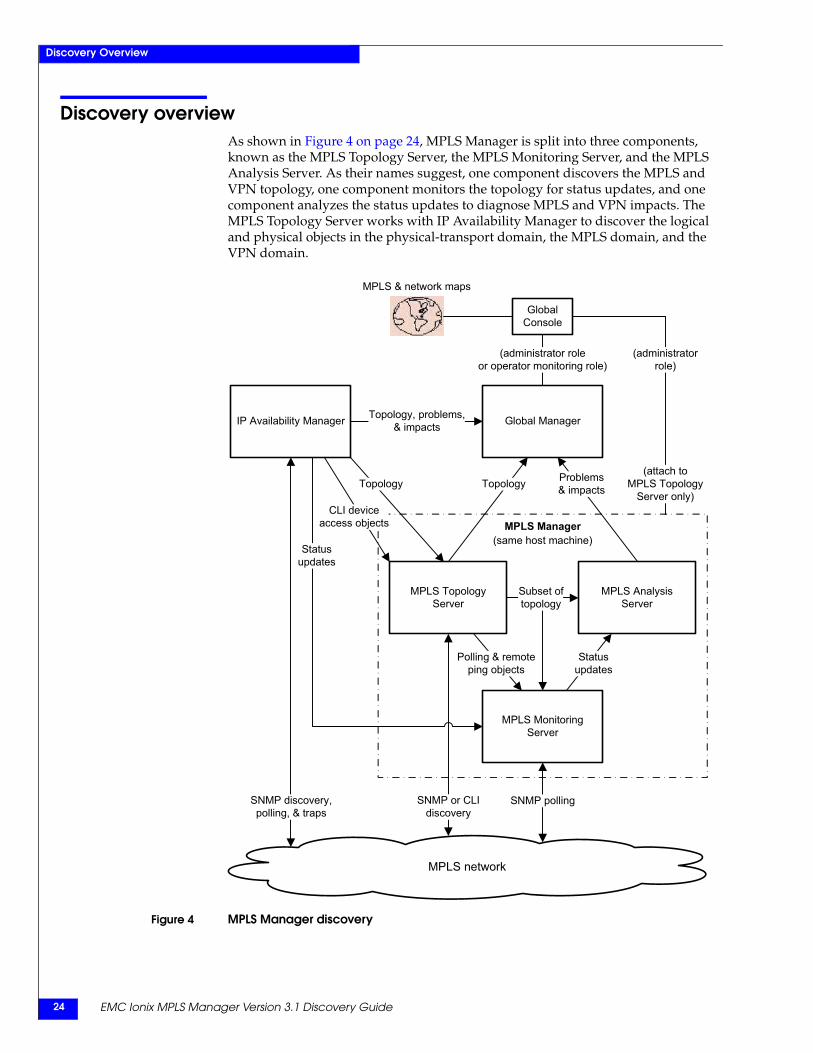
Discovery overviewAs shown in Figure 4 on page 24, MPLS Manager is split into three components, known as the MPLS Topology Server, the MPLS Monitoring Server, and the MPLS Analysis Server. As their names suggest, one component discovers the MPLS and VPN topology, one component monitors the topology for status updates, and one component analyzes the status updates to diagnose MPLS and VPN impacts. The MPLS Topology Server works with IP Availability Manager to discover the logical and physical objects in the physical-transport domain, the MPLS domain, and the VPN domain.
Figure 4 MPLS Manager discovery
MPLS network
SNMP pollingSNMP discovery,polling, & traps
CC API Server
MPLS Monitoring Server
(administratorrole)
Topology Problems& impacts
Statusupdates
Topology
SNMP or CLIdiscovery
MPLS Manager
MPLS TopologyServer
Subset oftopology
MPLS AnalysisServer
(same host machine)
IP Availability Manager Global ManagerTopology, problems,& impacts
MPLS & network maps
(administrator roleor operator monitoring role)
GlobalConsole
CLI deviceaccess objects
Polling & remoteping objects
(attach toMPLS Topology
Server only)
Statusupdates
IP Availability Manager discovery 25
Discovery Overview
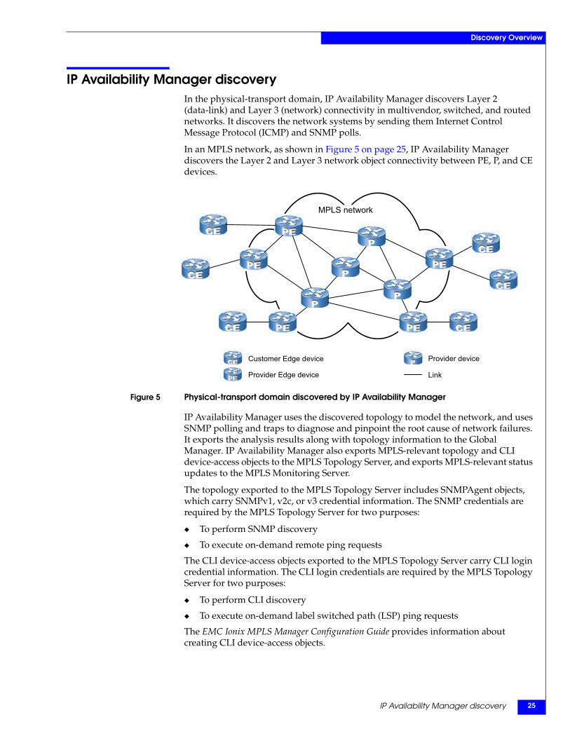
IP Availability Manager discoveryIn the physical-transport domain, IP Availability Manager discovers Layer 2 (data-link) and Layer 3 (network) connectivity in multivendor, switched, and routed networks. It discovers the network systems by sending them Internet Control Message Protocol (ICMP) and SNMP polls.
In an MPLS network, as shown in Figure 5 on page 25, IP Availability Manager discovers the Layer 2 and Layer 3 network object connectivity between PE, P, and CE devices.
Figure 5 Physical-transport domain discovered by IP Availability Manager
IP Availability Manager uses the discovered topology to model the network, and uses SNMP polling and traps to diagnose and pinpoint the root cause of network failures. It exports the analysis results along with topology information to the Global Manager. IP Availability Manager also exports MPLS-relevant topology and CLI device-access objects to the MPLS Topology Server, and exports MPLS-relevant status updates to the MPLS Monitoring Server.
The topology exported to the MPLS Topology Server includes SNMPAgent objects, which carry SNMPv1, v2c, or v3 credential information. The SNMP credentials are required by the MPLS Topology Server for two purposes:
◆ To perform SNMP discovery
◆ To execute on-demand remote ping requests
The CLI device-access objects exported to the MPLS Topology Server carry CLI login credential information. The CLI login credentials are required by the MPLS Topology Server for two purposes:
◆ To perform CLI discovery
◆ To execute on-demand label switched path (LSP) ping requests
The EMC Ionix MPLS Manager Configuration Guide provides information about creating CLI device-access objects.
MPLS network
Customer Edge device
Provider Edge device
Provider device
Link
EMC Ionix MPLS Manager Version 3.1 Discovery Guide26
Discovery Overview
MPLS Topology Server discoveryThe MPLS Topology Server discovers the MPLS and VPN logical topology and models (represents) that topology in its repository. It maps the MPLS and VPN topology to the network topology that is discovered by IP Availability Manager.
Imports topology from IP Availability ManagerFrom IP Availability Manager, the MPLS Topology Server imports the initial topology and CLI device-access objects. The topology consists of router and switch objects along with Interface, IP, IPNetwork, SNMPAgent, and other network objects that are associated with the router and switch objects.
Initiates discoveryAfter importing the initial topology and CLI device-access objects from IP Availability Manager, the MPLS Topology Server uses SNMP polling and/or CLI commands to query the imported devices for MPLS and VPN topology information. If SNMP polling fails or is not supported by a device, and assuming that CLI discovery is enabled, the MPLS Topology Server logs in to the device (through Telnet, SSH1 or SSH2) and issues CLI commands to query the device for the required information.
The EMC Ionix MPLS Manager Configuration Guide provides information about enabling CLI discovery.
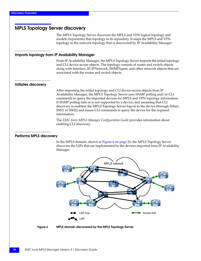
Performs MPLS discoveryIn the MPLS domain, shown in Figure 6 on page 26, the MPLS Topology Server discovers the LSPs that are implemented by the devices imported from IP Availability Manager.
Figure 6 MPLS domain discovered by the MPLS Topology Server
LSP hop Access link
LSP
MPLS network
MPLS Topology Server discovery 27
Discovery Overview
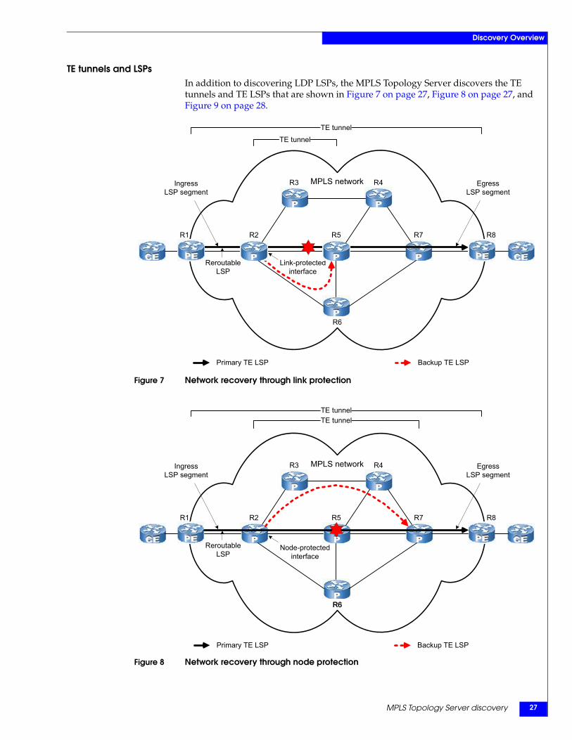
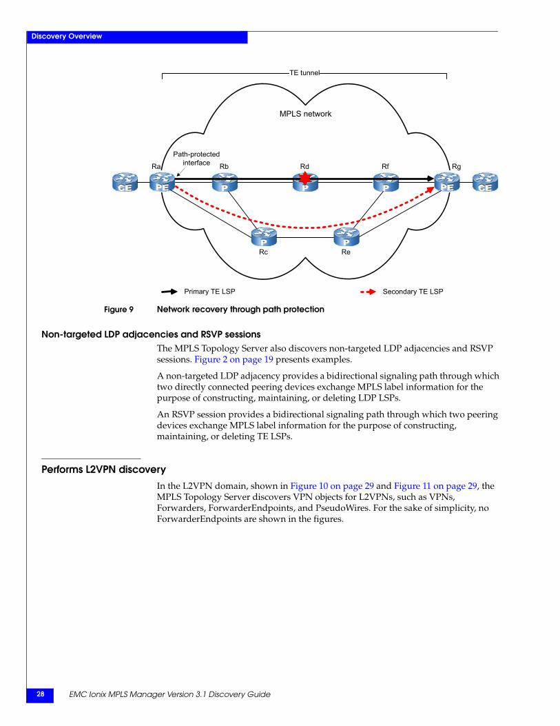
TE tunnels and LSPsIn addition to discovering LDP LSPs, the MPLS Topology Server discovers the TE tunnels and TE LSPs that are shown in Figure 7 on page 27, Figure 8 on page 27, and Figure 9 on page 28.
Figure 7 Network recovery through link protection
Figure 8 Network recovery through node protection
Link-protected interface
R1 R2 R5 R7 R8
MPLS network R4R3
Reroutable LSP
IngressLSP segment
EgressLSP segment
R6
TE tunnelTE tunnel
Backup TE LSPPrimary TE LSP
Node-protected interface
Reroutable LSP
R1 R2 R5
R6
R7 R8
MPLS network R4R3 EgressLSP segment
IngressLSP segment
R6
TE tunnelTE tunnel
Primary TE LSP Backup TE LSP
EMC Ionix MPLS Manager Version 3.1 Discovery Guide28
Discovery Overview
Figure 9 Network recovery through path protection
Non-targeted LDP adjacencies and RSVP sessionsThe MPLS Topology Server also discovers non-targeted LDP adjacencies and RSVP sessions. Figure 2 on page 19 presents examples.
A non-targeted LDP adjacency provides a bidirectional signaling path through which two directly connected peering devices exchange MPLS label information for the purpose of constructing, maintaining, or deleting LDP LSPs.
An RSVP session provides a bidirectional signaling path through which two peering devices exchange MPLS label information for the purpose of constructing, maintaining, or deleting TE LSPs.
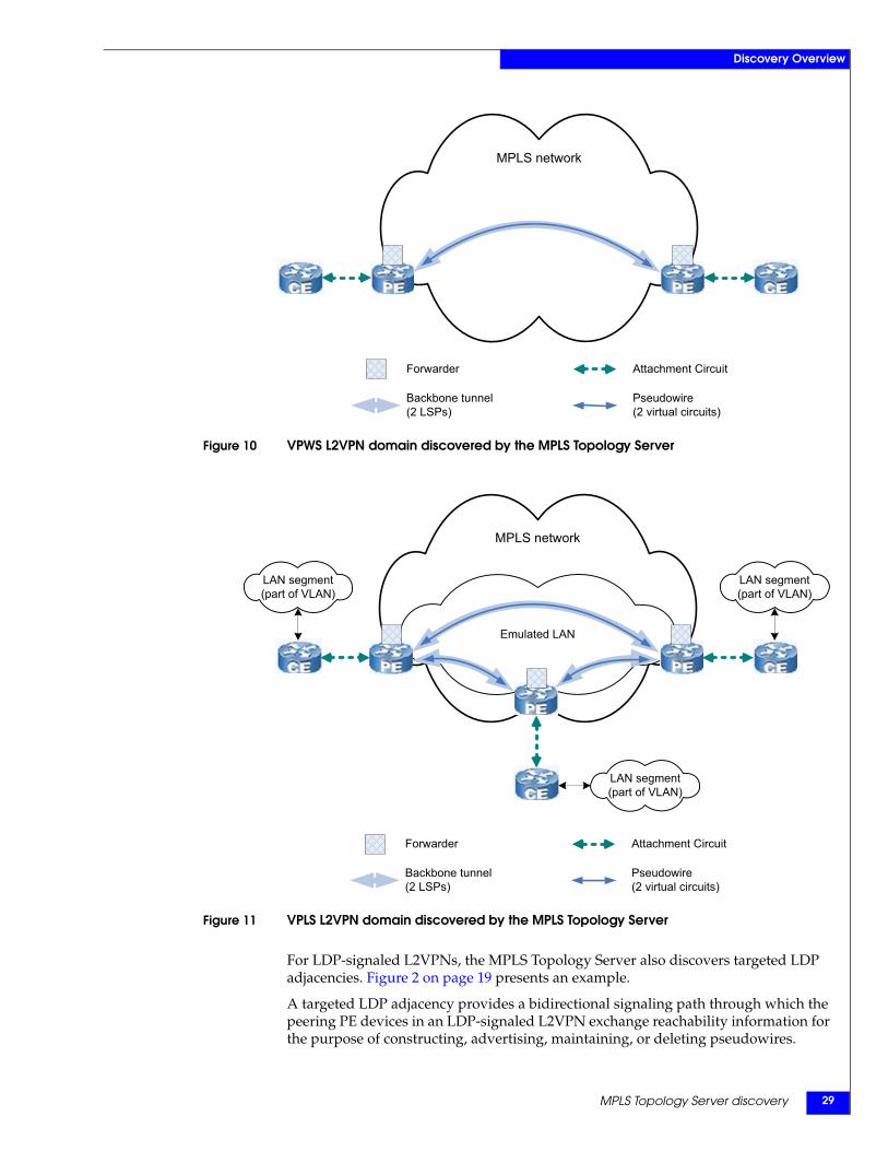
Performs L2VPN discoveryIn the L2VPN domain, shown in Figure 10 on page 29 and Figure 11 on page 29, the MPLS Topology Server discovers VPN objects for L2VPNs, such as VPNs, Forwarders, ForwarderEndpoints, and PseudoWires. For the sake of simplicity, no ForwarderEndpoints are shown in the figures.
Path-protectedinterfaceRa Rb Rd Rf Rg
MPLS network
ReRc
TE tunnel
Secondary TE LSPPrimary TE LSP
MPLS Topology Server discovery 29
Discovery Overview
Figure 10 VPWS L2VPN domain discovered by the MPLS Topology Server
Figure 11 VPLS L2VPN domain discovered by the MPLS Topology Server
For LDP-signaled L2VPNs, the MPLS Topology Server also discovers targeted LDP adjacencies. Figure 2 on page 19 presents an example.
A targeted LDP adjacency provides a bidirectional signaling path through which the peering PE devices in an LDP-signaled L2VPN exchange reachability information for the purpose of constructing, advertising, maintaining, or deleting pseudowires.
MPLS network
Backbone tunnel (2 LSPs)
Pseudowire (2 virtual circuits)
Forwarder Attachment Circuit
MPLS network
Emulated LAN
LAN segment(part of VLAN)
LAN segment(part of VLAN)
Backbone tunnel (2 LSPs)
Pseudowire (2 virtual circuits)
Forwarder Attachment Circuit
LAN segment(part of VLAN)
EMC Ionix MPLS Manager Version 3.1 Discovery Guide30
Discovery Overview
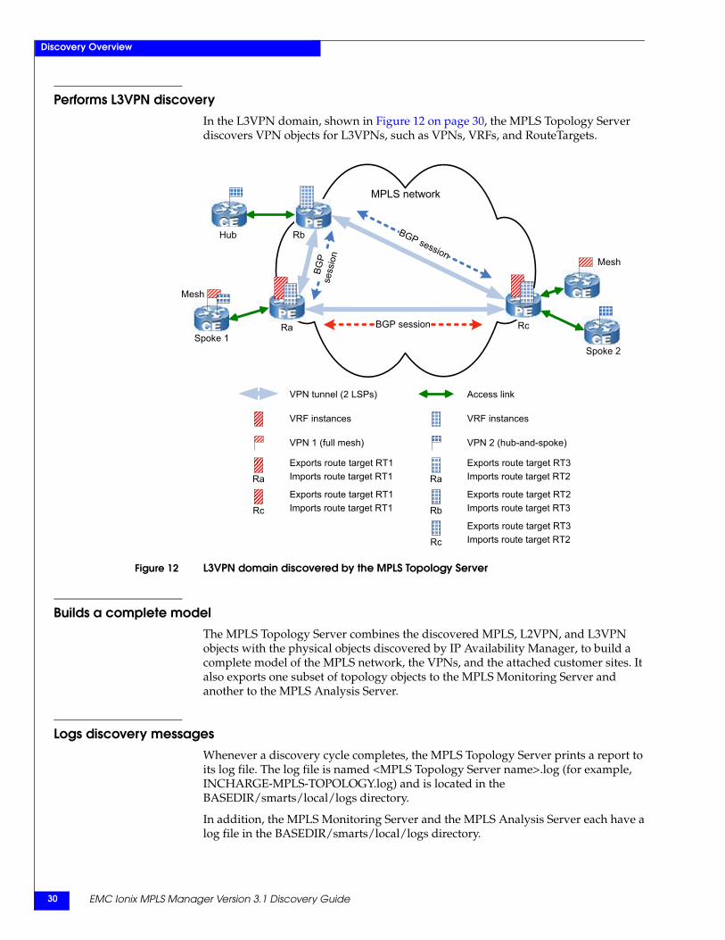
Performs L3VPN discoveryIn the L3VPN domain, shown in Figure 12 on page 30, the MPLS Topology Server discovers VPN objects for L3VPNs, such as VPNs, VRFs, and RouteTargets.
Figure 12 L3VPN domain discovered by the MPLS Topology Server
Builds a complete modelThe MPLS Topology Server combines the discovered MPLS, L2VPN, and L3VPN objects with the physical objects discovered by IP Availability Manager, to build a complete model of the MPLS network, the VPNs, and the attached customer sites. It also exports one subset of topology objects to the MPLS Monitoring Server and another to the MPLS Analysis Server.
Logs discovery messagesWhenever a discovery cycle completes, the MPLS Topology Server prints a report to its log file. The log file is named <MPLS Topology Server name>.log (for example, INCHARGE-MPLS-TOPOLOGY.log) and is located in the BASEDIR/smarts/local/logs directory.
In addition, the MPLS Monitoring Server and the MPLS Analysis Server each have a log file in the BASEDIR/smarts/local/logs directory.
VPN tunnel (2 LSPs) Access link
VRF instances VRF instances
MPLS network
Exports route target RT3Imports route target RT2RcRc
VPN 2 (hub-and-spoke)VPN 1 (full mesh)
Ra
Exports route target RT3Imports route target RT2Ra
Exports route target RT1Imports route target RT1
Exports route target RT2Imports route target RT3RcRbRc
Exports route target RT1Imports route target RT1
Spoke 2
Mesh
Spoke 1
BGP session
Ra Rc
Mesh
BGP
sess
ion
BGP session
Hub Rb
When discovery occurs 31
Discovery Overview
Creates CLI log filesDuring a discovery cycle and by default, the MPLS Topology Server creates a CLI log file for each device that it attempts to discover. The log file for a device may be populated with the following:
◆ Command and response information when CLI discovery of the device is successful
◆ Error information when access credentials are incorrect
◆ Failed command-response sequences when the device is being queried for a configuration that is specified for the device’s certification type but is not available on the device
For a successful-related log file, the MPLS Topology Server parses the response information in the log file to create topology objects in its repository.
A CLI log file is named CLI-<device vendor>-<device name>.txt (for example, CLI-CISCO-lab-gw.emc.com.txt). All CLI log files are located in the BASEDIR/smarts/local/logs directory.
The MPLS Topology Server overwrites the CLI log files during each successive discovery cycle.
When discovery occursThe MPLS Topology Server initiates a discovery cycle of the MPLS and VPN objects whenever:
◆ IP Availability Manager is added as a source to the MPLS Topology Server, as explained in Chapter 7, ”Preparing and Initiating Discovery.”
◆ IP Availability Manager completes a discovery cycle.
By default, each time IP Availability Manager completes a discovery cycle, the MPLS Topology Server performs a topology synchronization to determine which topology to import from IP Availability Manager, by comparing the current topology with the previously imported topology.
If the MPLS Topology Server finds a new router or switch, or finds an already known router or switch that has a newer discovery timestamp, the MPLS Topology Server performs its own discovery by sending SNMP polls and/or CLI commands to that device to discover or rediscover the device’s MPLS and VPN objects.
◆ The MPLS Topology Server is restarted or communication is lost and then reestablished between the MPLS Topology Server and IP Availability Manager.

EMC Ionix MPLS Manager Version 3.1 Discovery Guide32
Discovery Overview

MPLS VPN Overlapping IP Discovery 33
2
This chapter introduces the VPN-Tagging Server and describes how the server solves the overlapping IP discovery problem. It consists of the following sections:
◆ Introducing the VPN-Tagging Server.......................................................................... 34◆ Functional overview ...................................................................................................... 36◆ Discovery in the Cisco environment ........................................................................... 37◆ Discovery in the Alcatel-Lucent environment ........................................................... 39◆ Discovery assumptions and criteria ............................................................................ 42◆ Overlapping IP naming format.................................................................................... 42◆ Configuring the VPN-Tagging Server......................................................................... 43◆ Starting the VPN-Tagging Server................................................................................. 43
MPLS VPN OverlappingIP Discovery
EMC Ionix MPLS Manager Version 3.1 Discovery Guide34
MPLS VPN Overlapping IP Discovery
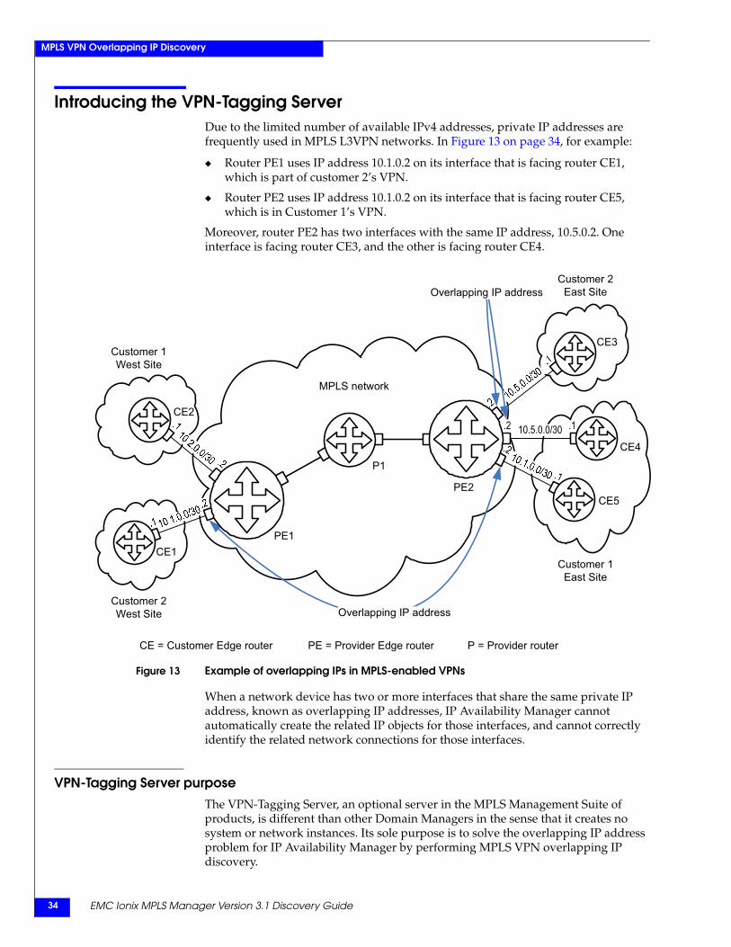
Introducing the VPN-Tagging ServerDue to the limited number of available IPv4 addresses, private IP addresses are frequently used in MPLS L3VPN networks. In Figure 13 on page 34, for example:
◆ Router PE1 uses IP address 10.1.0.2 on its interface that is facing router CE1, which is part of customer 2’s VPN.
◆ Router PE2 uses IP address 10.1.0.2 on its interface that is facing router CE5, which is in Customer 1’s VPN.
Moreover, router PE2 has two interfaces with the same IP address, 10.5.0.2. One interface is facing router CE3, and the other is facing router CE4.
Figure 13 Example of overlapping IPs in MPLS-enabled VPNs
When a network device has two or more interfaces that share the same private IP address, known as overlapping IP addresses, IP Availability Manager cannot automatically create the related IP objects for those interfaces, and cannot correctly identify the related network connections for those interfaces.
VPN-Tagging Server purposeThe VPN-Tagging Server, an optional server in the MPLS Management Suite of products, is different than other Domain Managers in the sense that it creates no system or network instances. Its sole purpose is to solve the overlapping IP address problem for IP Availability Manager by performing MPLS VPN overlapping IP discovery.
PE1CE1
Customer 1West Site
Customer 2West Site
Customer 2East Site
MPLS network
Customer 1East Site
CE3
CE4
CE2
P1
CE5PE2
.1
Overlapping IP address
Overlapping IP address
10.5.0.0/30
PE = Provider Edge router P = Provider router
.2
CE = Customer Edge router
Introducing the VPN-Tagging Server 35
MPLS VPN Overlapping IP Discovery
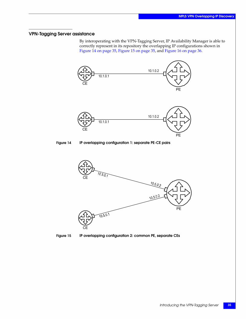
VPN-Tagging Server assistanceBy interoperating with the VPN-Tagging Server, IP Availability Manager is able to correctly represent in its repository the overlapping IP configurations shown in Figure 14 on page 35, Figure 15 on page 35, and Figure 16 on page 36.
Figure 14 IP overlapping configuration 1: separate PE-CE pairs
Figure 15 IP overlapping configuration 2: common PE, separate CEs
10.1.0.1
PE
10.1.0.2
CE
PE
10.1.0.2
CE
10.1.0.1
PE
CE
CE
EMC Ionix MPLS Manager Version 3.1 Discovery Guide36
MPLS VPN Overlapping IP Discovery
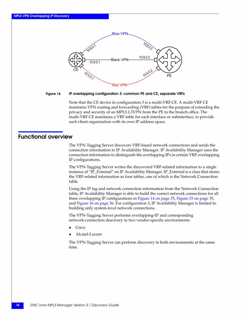
Figure 16 IP overlapping configuration 3: common PE and CE, separate VRFs
Note that the CE device in configuration 3 is a multi-VRF CE. A multi-VRF CE maintains VPN routing and forwarding (VRF) tables for the purpose of extending the privacy and security of an MPLS L3VPN from the PE to the branch office. The multi-VRF CE maintains a VRF table for each interface or subinterface, to provide each client organization with its own IP address space.
Functional overviewThe VPN-Tagging Server discovers VRF-based network connections and sends the connection information to IP Availability Manager. IP Availability Manager uses the connection information to distinguish the overlapping IPs in certain VRF overlapping IP configurations.
The VPN-Tagging Server writes the discovered VRF-related information to a single instance of “IP_External” on IP Availability Manager. IP_External is a class that stores the VRF-related information as four tables, one of which is the Network Connection table.
Using the IP tag and network connection information from the Network Connection table, IP Availability Manager is able to build the correct network connections for all three overlapping IP configurations in Figure 14 on page 35, Figure 15 on page 35, and Figure 16 on page 36. For configuration 3, IP Availability Manager is limited to building only system-level network connections.
The VPN-Tagging Server performs overlapping-IP and corresponding network-connection discovery in two vendor-specific environments:
◆ Cisco
◆ Alcatel-Lucent
The VPN-Tagging Server can perform discovery in both environments at the same time.
Blue VPN
Red VPN
10.9.0.110.9.0.2
PE
Black VPN
CE
Discovery in the Cisco environment 37
MPLS VPN Overlapping IP Discovery
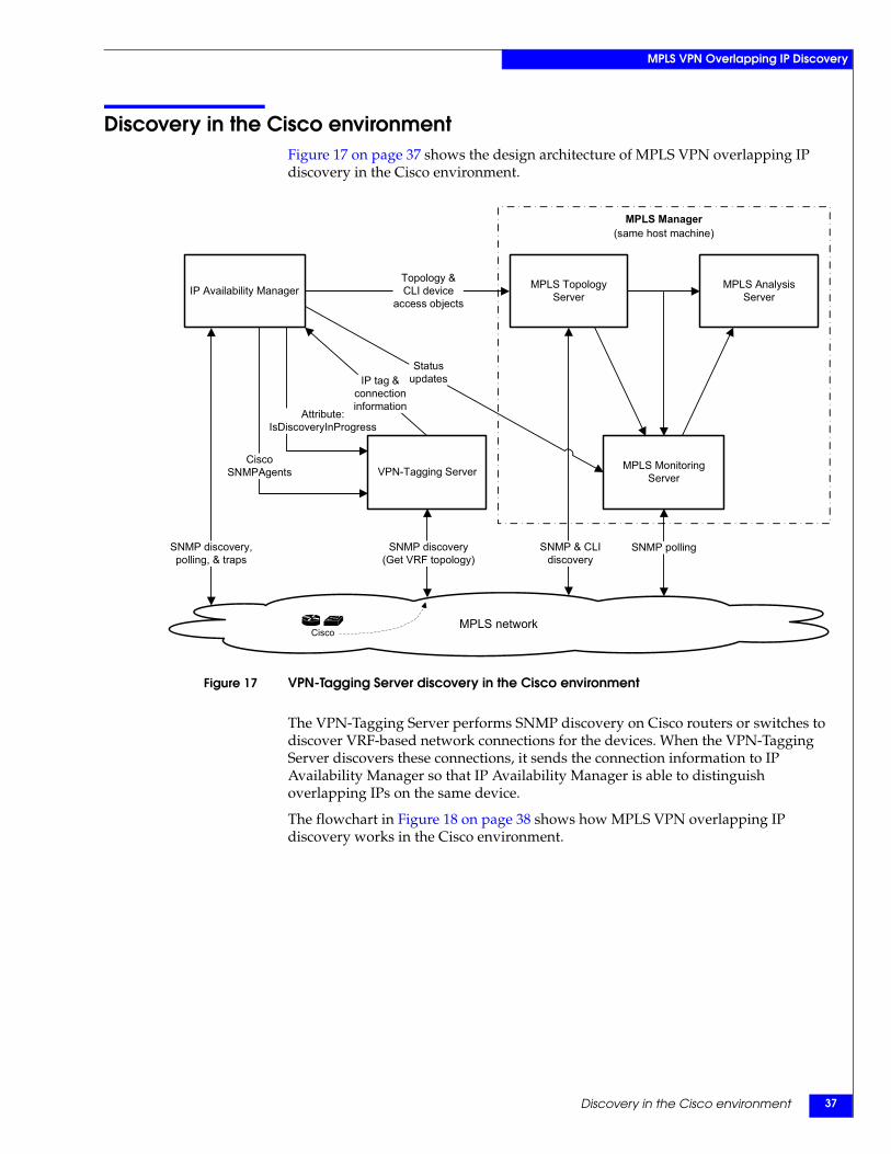
Discovery in the Cisco environmentFigure 17 on page 37 shows the design architecture of MPLS VPN overlapping IP discovery in the Cisco environment.
Figure 17 VPN-Tagging Server discovery in the Cisco environment
The VPN-Tagging Server performs SNMP discovery on Cisco routers or switches to discover VRF-based network connections for the devices. When the VPN-Tagging Server discovers these connections, it sends the connection information to IP Availability Manager so that IP Availability Manager is able to distinguish overlapping IPs on the same device.
The flowchart in Figure 18 on page 38 shows how MPLS VPN overlapping IP discovery works in the Cisco environment.
Attribute:IsDiscoveryInProgress
MPLS network
SNMP pollingSNMP & CLIdiscovery
SNMP discovery(Get VRF topology)
Topology &CLI device
access objects
Statusupdates
VPN-Tagging Server MPLS Monitoring Server
MPLS TopologyServer
MPLS AnalysisServer
IP tag &connectioninformation
MPLS Manager(same host machine)
CiscoSNMPAgents
SNMP discovery,polling, & traps
IP Availability Manager
Cisco
EMC Ionix MPLS Manager Version 3.1 Discovery Guide38
MPLS VPN Overlapping IP Discovery
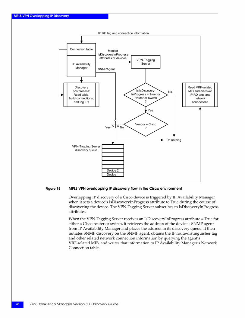
Figure 18 MPLS VPN overlapping IP discovery flow in the Cisco environment
Overlapping IP discovery of a Cisco device is triggered by IP Availability Manager when it sets a device’s IsDiscoveryInProgress attribute to True during the course of discovering the device. The VPN-Tagging Server subscribes to IsDiscoveryInProgress attributes.
When the VPN-Tagging Server receives an IsDiscoveryInProgress attribute = True for either a Cisco router or switch, it retrieves the address of the device’s SNMP agent from IP Availability Manager and places the address in its discovery queue. It then initiates SNMP discovery on the SNMP agent, obtains the IP route-distinguisher tag and other related network connection information by querying the agent’s VRF-related MIB, and writes that information to IP Availability Manager’s Network Connection table.
Monitor IsDiscoveryInProgress attributes of devices
IP RD tag and connection information
SNMPAgent
Connection table
IP Availability Manager
VPN-TaggingServer
Discoverypostprocess:Read table,
build connections,and tag IPs
No
Yes
Read VRF-relatedMIB and discoverIP RD tags and
network connections
Do nothing
VPN-Tagging Serverdiscovery queue
Vendor = Cisco?
Is IsDiscovery-InProgress = True for
Router or Switch?
Device 1Device 2
Yes No
Discovery in the Alcatel-Lucent environment 39
MPLS VPN Overlapping IP Discovery
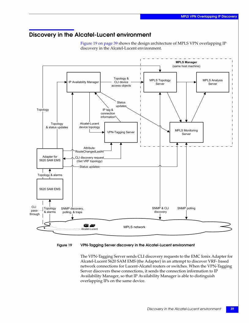
Discovery in the Alcatel-Lucent environmentFigure 19 on page 39 shows the design architecture of MPLS VPN overlapping IP discovery in the Alcatel-Lucent environment.
Figure 19 VPN-Tagging Server discovery in the Alcatel-Lucent environment
The VPN-Tagging Server sends CLI discovery requests to the EMC Ionix Adapter for Alcatel-Lucent 5620 SAM EMS (the Adapter) in an attempt to discover VRF- based network connections for Lucent-Alcatel routers or switches. When the VPN-Tagging Server discovers these connections, it sends the connection information to IP Availability Manager, so that IP Availability Manager is able to distinguish overlapping IPs on the same device.
MPLS network
SNMP pollingSNMP & CLIdiscovery
SNMP discovery,polling, & traps
Topology& alarms
Status updates
Topology
Topology &CLI device
access objects
Statusupdates
IP Availability Manager
VPN-Tagging Server
Attribute:RouteChangedLastAt
Adapter for 5620 SAM EMS
Topology& status updates
MPLS Monitoring Server
MPLS TopologyServer
MPLS AnalysisServer
Alcatel-Lucentdevice topology
IP tag &connectioninformation
MPLS Manager(same host machine)
CLI discovery request(Get VRF topology)
Topology & alarms
5620 SAM EMS
CLI_pass-
through
Alcatel-Lucent
EMC Ionix MPLS Manager Version 3.1 Discovery Guide40
MPLS VPN Overlapping IP Discovery
Overlapping IP discovery of Alcatel-Lucent devices is triggered in any of the following ways:
◆ When the VPN-Tagging Server starts up.
At startup, the VPN-Topology Server imports a list of Alcatel-Lucent devices from its source IP Availability Manager and performs a full discovery. The devices are identified in the Global_TopologyCollection objects that the Adapter creates in IP Availability Manager.
◆ When the VPN-Tagging Server receives, from IP Availability Manager, a DiscoveredLastAt attribute update for a Global_TopologyCollection object.
The Adapter changes the date of a global object’s DiscoveredLastAt attribute whenever the Adapter:
• Connects to IP Availability Manager and creates the global object.
• Adds new devices to the global object.
The VPN-Tagging Server subscribes to DiscoveredLastAt attribute updates.
◆ When the VPN-Tagging Server receives, from the Adapter, a RouteChangedLastAt attribute update for an Alcatel-Lucent device.
The Adapter sets a device’s RouteChangedLastAt attribute to a new date whenever the Adapter learns of a new or changed route for the device. The VPN-Tagging Server subscribes to RouteChangedLastAt attribute updates.
When the VPN-Tagging Server receives a RouteChangedLastAt attribute update for a device, it places the device in its discovery queue. During the next scheduled full-discovery interval, as defined in the BASEDIR/smarts/conf/vpn-tagging/vpn-tagging.conf file, the VPN-Tagging Server will discover the device.
When initiating a discovery of an Alcatel-Lucent device, the VPN-Tagging Server sends to the Adapter a CLI request that includes the device’s name. The Adapter executes the request and returns the output to the VPN-Tagging Server.
A CLI request contains the following CLI command:
show router <VRF name> route-table
The execution of the CLI command yields the IP route-distinguisher tag and other related network connection information for the target device. The VPN-Tagging Server writes that information to IP Availability Manager’s Network Connection table.
Discovery in the Alcatel-Lucent environment 41
MPLS VPN Overlapping IP Discovery
On-demand discoveryIn addition to periodic discovery, on-demand discovery of Alcatel-Lucent devices is supported. An on-demand discovery can be initiated in any of the following ways:
◆ To initiate a discovery of all the devices in the VPN-Tagging Server’s discovery queue, go to the BASEDIR/smarts/bin directory in the MPLS Management Suite installation area and enter either of the following commands:
dmctl -s <VPN-Tagging Server name> invoke VPNTagging_Manager::VPNTagging-Manager::invoke5620SAMDiscovery
dmctl -s <VPN-Tagging Server name> put VPNTagging_Manager::VPNTagging-Manager::Force5620SAMDiscovery
TRUE
◆ To initiate a discovery of all the devices in the Global_TopologyCollection objects, go to the BASEDIR/smarts/bin directory in the MPLS Management Suite installation area and enter the following command:
dmctl -s <VPN-Tagging Server name> put VPNTagging_Manager::VPNTagging-Manager::invokeDomainDiscovery
<domain name>
Where <domain name> may be an IP Availability Manager’s name or an Adapter’s name.
Adapter ConfigurationThe EMC Ionix Adapter for Alcatel-Lucent 5620 SAM EMS User Guide describes the Adapter in detail and presents configuration procedures for the Adapter.
Configuring the connection from the Adapter to a Domain Manager, such as IP Availability Manager or the MPLS Topology Server, is achieved by setting a particular parameter in the Adapter’s emsConfig.import file. For example, setting the AMServerName parameter value to the name of an IP Availability Manager will cause the Adapter to forward to that IP Availability Manager the topology data that is expected by an IP Availability Manager.
As an aside, the Adapter will set the ServiceName attribute of each object that it forwards to a Domain Manager to the name of the Adapter, to identify the Adapter as the object’s source. By doing so, any other Domain Manager that imports or is assigned these objects will be able to use the ServiceName value to subscribe to the Adapter for status updates. By this means, for example, the VPN-Topology Server is able to subscribe to the Adapter for RouteChangedLastAt attribute updates.
EMC Ionix MPLS Manager Version 3.1 Discovery Guide42
MPLS VPN Overlapping IP Discovery
Discovery assumptions and criteriaMPLS VPN overlapping IP discovery is based on the following assumptions and criteria:
◆ The loopback IP address of each CE device is unique and known.
◆ The loopback IP address of each CE device must be used to advertise the route in the VRF; that is, the CE device can be identified by its loopback IP address.
◆ The Loopback IP address is not tagged by any IP tag filter that a user has created by using the IP tagging feature in IP Availability Manager.
◆ Each VRF has a route distinguisher.
IP objects of interfaces associated with a single VRF have the same 8-byte route distinguisher value. The purpose of the route distinguisher is to allow the creation of distinct routes to separate instances of the same (overlapping) IPv4 address.
◆ VRF name is unique on each single device.
◆ IP address is unique on each CE device. This assumption is not applicable to the overlapping IP configuration shown in Figure 16 on page 36. For this reason, the overlapping IP discovery feature cannot be used to build interface-level network connections between the PE and CE for the configuration in Figure 16.
Overlapping IP naming formatEMC Ionix applications require unique instance name in their repositories. The conventional IP instance naming method, which is adding a prefix "IP-" to the IP address to create the name of the instance (for example, "IP-10.0.1.14"), is not applicable for overlapping IP addresses.
The Name of an overlapping IP instance will be in the following format:
IP-<IP address>/<route distinguisher>
The DisplayName attribute will be in the following format:
<route distinguisher>:<IP address> [host system name]
For example, router R1 has a VRF named "red." Interface 15, which is associated with this VRF, has a duplicated IP address 10.0.1.14 and is part of the subnet 10.0.1.12/30. The route distinguisher of VRF "red" is "4445:401." The name of this IP instance will be:
IP-10.0.1.14/4445:401
And its DisplayName will be:
4445:401:10.0.1.14 [R1]
In addition, the Tag attribute of the IP instance will have a value of "4445:401."
Configuring the VPN-Tagging Server 43
MPLS VPN Overlapping IP Discovery
Configuring the VPN-Tagging ServerBy default, the VPN-Tagging Server is configured to connect to an IP Availability Manager named INCHARGE-AM. You can edit the VPN-Tagging Server’s configuration file named vpn-tagging.conf and change this name or add one or more additional IP Availability Managers as connections to the VPN-Tagging Server.
The EMC Ionix MPLS Manager Configuration Guide describes the parameters in the vpn-tagging.conf file and provides instructions for modifying the parameters. The configuration guide also describes the parameters and provides instructions for:
◆ Enabling IP Availability Manager to discover overlapping IP addresses.
◆ Enabling IP Availability Manager to interoperate with the VPN-Tagging Server.
Starting the VPN-Tagging ServerAs a prerequisite, the VPN-Tagging Server must be started before IP Availability Manager begins its discovery.
EMC Corporation recommends installing EMC Ionix products as services. On a UNIX system, a sample command for installing the VPN-Tagging Server as a service is:
/opt/InCharge7/MPLS/smarts/bin/sm_service install--force--unmanaged--startmode=runonce--name=ic-vpn-tagging--description="EMC Ionix VPN Tagging Server"
/opt/InCharge7/MPLS/smarts/bin/sm_server--name=VPN-TAGGING--config=vpn-tagging--ignore-restore-errors--output
The command for starting the service is:
/opt/InCharge7/MPLS/smarts/bin/sm_service start ic-vpn-tagging
At startup, the VPN-Tagging Server reads the vpn-tagging.conf file, saves the configuration information in that file to the repository, and attempts to connect to the one or more IP Availability Managers that are specified in the file.
If an IP Availability Manager is not running, the VPN-Tagging Server will periodically attempt to connect to the IP Availability Manager.

EMC Ionix MPLS Manager Version 3.1 Discovery Guide44
MPLS VPN Overlapping IP Discovery
Discovery Process 45
3
This chapter describes the types of discovery performed by MPLS Manager and explains the phases of the discovery process. It consists of the following sections:
◆ Discovery process overview......................................................................................... 46◆ Discovery process details .............................................................................................. 48
Discovery Process
EMC Ionix MPLS Manager Version 3.1 Discovery Guide46
Discovery Process
Discovery process overviewDuring the discovery process, the MPLS Topology Server component of MPLS Manager uses instances of certain EMC Ionix object classes to create within its repository a data model representation of the discovered MPLS and VPN topology. The various data models supported by the MPLS Topology Server are shown in Chapter 4, ”Discovery of MPLS Objects,” Chapter 5, ”Discovery of L2VPN Objects,” and Chapter 6, ”Discovery of L3VPN Objects.”
The MPLS Topology Server discovers MPLS and VPN specific objects based on the topology that is initially imported from the IP Availability Manager source. The topology consists of router and switch objects, router and switch containment objects, and router and switch connectivity objects.
CLI device-access objects are also imported from IP Availability Manager.
Upon sending SNMP polls/and or CLI commands to the imported devices to discover the MPLS and VPN topology, the MPLS Topology Server models (represents) the discovered topology in its repository, and maps the discovered MPLS and VPN topology to the router and switch topology that is discovered by IP Availability Manager.
Topology information needed for monitoring and analysis is then imported from the MPLS Topology Server by the MPLS Monitoring Server and the MPLS Analysis Server. The subset of topology imported by the MPLS Monitoring Server consists of just those classes and class attributes that are related to monitoring. The subset of topology imported by the MPLS Analysis Server consists of just those classes and class attributes that are related to causality.
Discovery typesThe MPLS Topology Server performs three types of discovery:
◆ MPLS discovery
◆ L2VPN discovery
◆ L3VPN discovery
During the discovery process, all three discoveries run in parallel. During the postprocessing phase, the discovery process associates the discovered L2VPN and L3VPN topology with the discovered MPLS topology.
Summary of MPLS discoveryThe MPLS Topology Server performs the following steps to discover MPLS topology:
1. Imports initial topology and CLI device-access objects from IP Availability Manager and adds the data to its repository.
2. Probes the imported router and switch devices for MPLS-relevant topology information.
3. Creates in its repository instances of the discovered MPLS topology objects and the relationships between them.
4. Combines the information that is collected from the various probes to create additional MPLS objects and relationships between the objects in its repository.
Discovery process overview 47
Discovery Process
5. Exports device and MPLS topology to the Global Manager.
6. Exports a subset of the device and MPLS topology to the MPLS Monitoring Server and the MPLS Analysis Server.
Summary of L2VPN discoveryThe MPLS Topology Server performs the following steps to discover L2VPN topology:
1. Probes the imported router and switch devices for L2VPN information and creates common L2VPN objects, LDP-signaled L2VPN objects, BGP-signaled L2VPN objects, and their relationships in its repository.
2. Combines the information that is collected from the various probes to create additional L2VPN objects and relationships between the objects in its repository.
3. Creates relationships that associate the discovered L2VPN objects with the discovered MPLS objects.
4. Exports the L2VPN topology to the Global Manager.
5. Exports a subset of the L2VPN topology to the MPLS Monitoring Server and the MPLS Analysis Server.
Summary of L3VPN discoveryThe MPLS Topology Server performs the following steps to discover L3VPN topology:
1. Probes the imported router and switch devices for L3VPN information and creates L3VPN objects and their relationships in its repository.
2. Combines the information that is collected from the various probes to create additional L3VPN objects and relationships between the objects in its repository.
3. Creates relationships that associate the discovered L3VPN objects with the discovered MPLS objects.
4. Exports the L3VPN topology to the Global Manager.
5. Exports a subset of the L3VPN topology to the MPLS Monitoring Server and the MPLS Analysis Server.
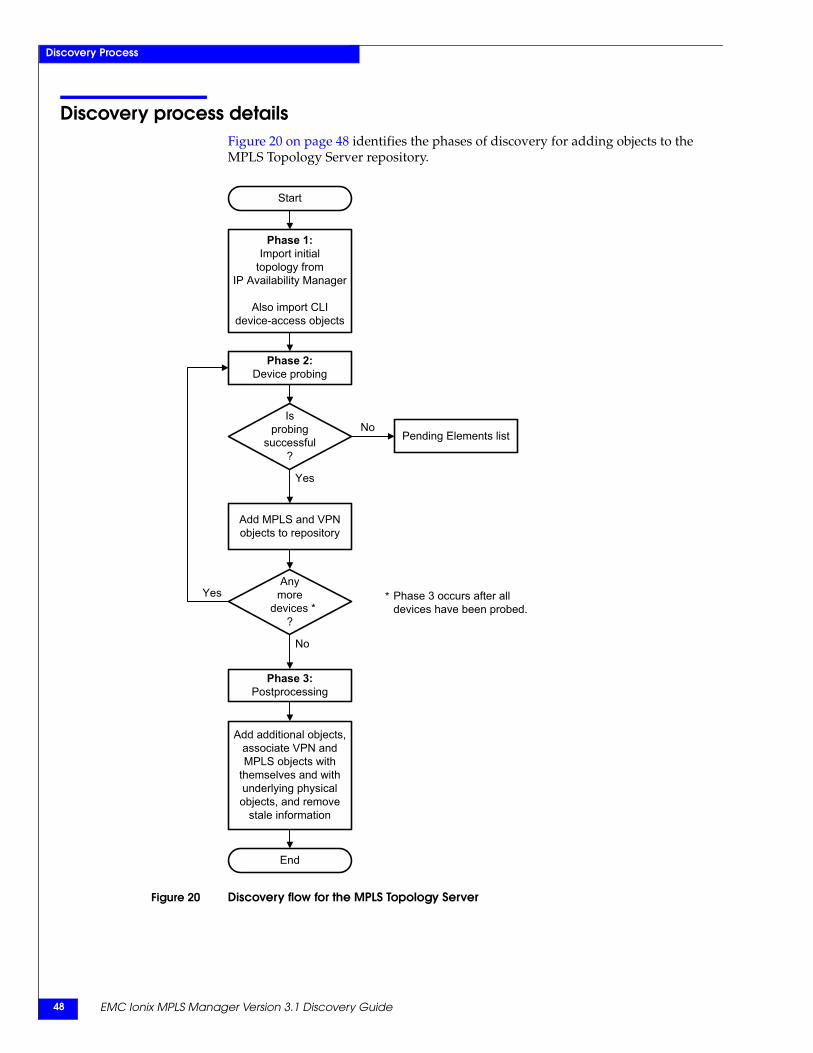
EMC Ionix MPLS Manager Version 3.1 Discovery Guide48
Discovery Process
Discovery process detailsFigure 20 on page 48 identifies the phases of discovery for adding objects to the MPLS Topology Server repository.
Figure 20 Discovery flow for the MPLS Topology Server
Phase 2:Device probing
Add MPLS and VPNobjects to repository
Phase 1:Import initial
topology fromIP Availability Manager
Also import CLIdevice-access objects
Start
End
Add additional objects, associate VPN and MPLS objects with
themselves and with underlying physical objects, and remove
stale information
Phase 3:Postprocessing
Pending Elements list
Isprobing
successful?
Yes
No
Anymore
devices *?
No
Yes Phase 3 occurs after all devices have been probed.
*
Discovery process details 49
Discovery Process
The discovery phases are:
1. Import initial topology from IP Availability Manager.
2. Probe each imported device for MPLS and VPN topology information and relationships.
3. Post-process the discovery information.
Phase 1: Import initial topologyThe first phase of the discovery process is carried out by MPLS Topology Server data exchange adapter (DXA) programs that import topology and CLI device-access objects from IP Availability Manager. By default, the topology-import DXA program imports instances of the following EMC Ionix object classes:
Note: The indentations in the bullet list indicate class hierarchy.
◆ Router
◆ Switch
◆ Chassis
◆ Card
◆ Port
◆ Interface
◆ NetworkConnection
• Cable
• TrunkCable
◆ IP
◆ VPNIP
◆ VPNIPNetwork
◆ Partition
◆ AD_PersistentDataSet
◆ SNMPAgent
• VRAgent
Users can customize the topology import by enabling and customizing MPLS light discovery in IP Availability Manager. The EMC Ionix IP Management Suite Configuration Guide provides instructions for performing this task.
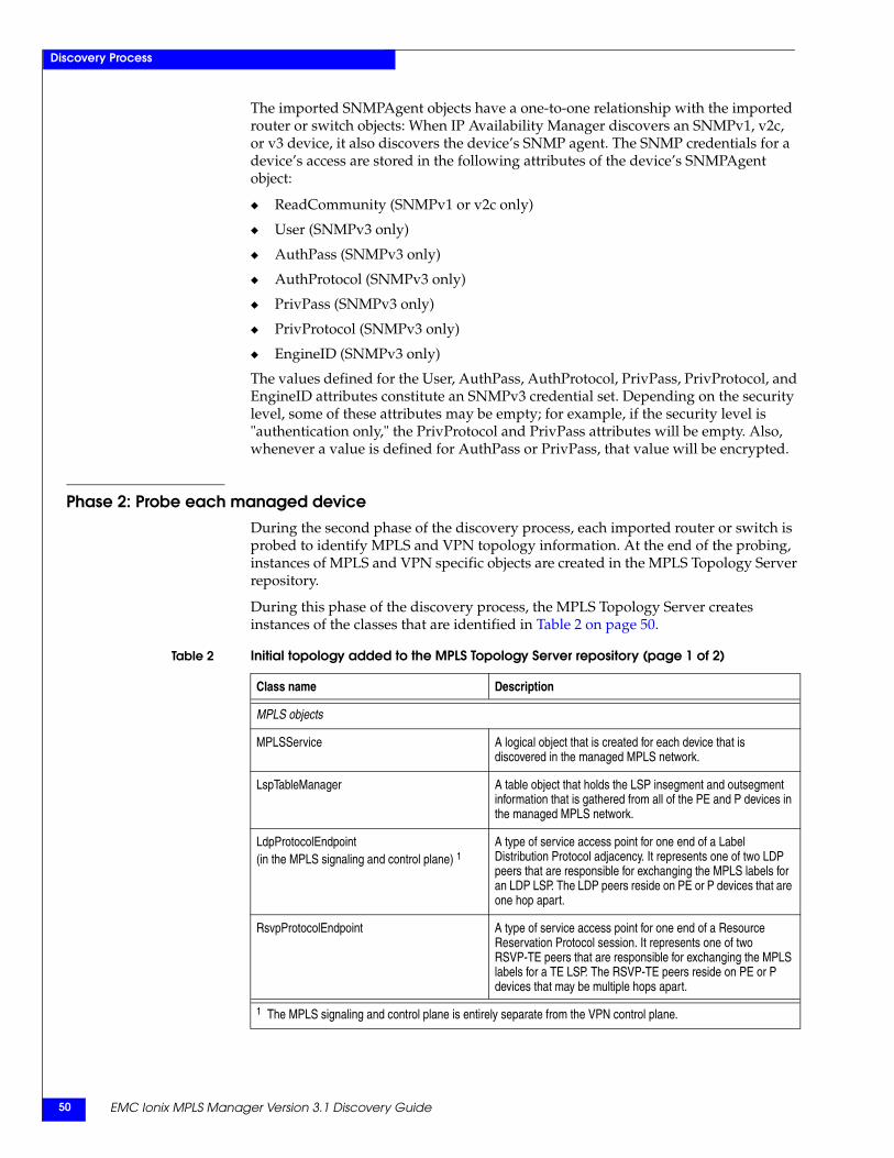
EMC Ionix MPLS Manager Version 3.1 Discovery Guide50
Discovery Process
The imported SNMPAgent objects have a one-to-one relationship with the imported router or switch objects: When IP Availability Manager discovers an SNMPv1, v2c, or v3 device, it also discovers the device’s SNMP agent. The SNMP credentials for a device’s access are stored in the following attributes of the device’s SNMPAgent object:
◆ ReadCommunity (SNMPv1 or v2c only)
◆ User (SNMPv3 only)
◆ AuthPass (SNMPv3 only)
◆ AuthProtocol (SNMPv3 only)
◆ PrivPass (SNMPv3 only)
◆ PrivProtocol (SNMPv3 only)
◆ EngineID (SNMPv3 only)
The values defined for the User, AuthPass, AuthProtocol, PrivPass, PrivProtocol, and EngineID attributes constitute an SNMPv3 credential set. Depending on the security level, some of these attributes may be empty; for example, if the security level is "authentication only," the PrivProtocol and PrivPass attributes will be empty. Also, whenever a value is defined for AuthPass or PrivPass, that value will be encrypted.
Phase 2: Probe each managed deviceDuring the second phase of the discovery process, each imported router or switch is probed to identify MPLS and VPN topology information. At the end of the probing, instances of MPLS and VPN specific objects are created in the MPLS Topology Server repository.
During this phase of the discovery process, the MPLS Topology Server creates instances of the classes that are identified in Table 2 on page 50.
Table 2 Initial topology added to the MPLS Topology Server repository (page 1 of 2)
Class name Description
MPLS objects
MPLSService A logical object that is created for each device that is discovered in the managed MPLS network.
LspTableManager A table object that holds the LSP insegment and outsegment information that is gathered from all of the PE and P devices in the managed MPLS network.
LdpProtocolEndpoint(in the MPLS signaling and control plane) 1
A type of service access point for one end of a Label Distribution Protocol adjacency. It represents one of two LDP peers that are responsible for exchanging the MPLS labels for an LDP LSP. The LDP peers reside on PE or P devices that are one hop apart.
RsvpProtocolEndpoint A type of service access point for one end of a Resource Reservation Protocol session. It represents one of two RSVP-TE peers that are responsible for exchanging the MPLS labels for a TE LSP. The RSVP-TE peers reside on PE or P devices that may be multiple hops apart.
1 The MPLS signaling and control plane is entirely separate from the VPN control plane.
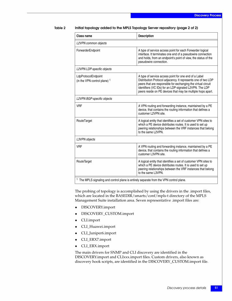
Discovery process details 51
Discovery Process
The probing of topology is accomplished by using the drivers in the .import files, which are located in the BASEDIR/smarts/conf/mpls-t directory of the MPLS Management Suite installation area. Seven representative .import files are:
◆ DISCOVERY.import
◆ DISCOVERY_CUSTOM.import
◆ CLI.import
◆ CLI_Huawei.import
◆ CLI_Juniper6.import
◆ CLI_ERX7.import
◆ CLI_ERX.import
The main drivers for SNMP and CLI discovery are identified in the DISCOVERY.import and CLIxxx.import files. Custom drivers, also known as discovery hook scripts, are identified in the DISCOVERY_CUSTOM.import file.
L2VPN common objects
ForwarderEndpoint A type of service access point for each Forwarder logical interface. It terminates one end of a pseudowire connection and holds, from an endpoint's point of view, the status of the pseudowire connection.
L2VPN LDP-specific objects
LdpProtocolEndpoint(in the VPN control plane) 1
A type of service access point for one end of a Label Distribution Protocol adjacency. It represents one of two LDP peers that are responsible for exchanging the virtual circuit identifiers (VC IDs) for an LDP-signaled L2VPN. The LDP peers reside on PE devices that may be multiple hops apart.
L2VPN BGP-specific objects
VRF A VPN routing and forwarding instance, maintained by a PE device, that contains the routing information that defines a customer L2VPN site.
RouteTarget A logical entity that identifies a set of customer VPN sites to which a PE device distributes routes. It is used to set up peering relationships between the VRF instances that belong to the same L2VPN.
L3VPN objects
VRF A VPN routing and forwarding instance, maintained by a PE device, that contains the routing information that defines a customer L3VPN site.
RouteTarget A logical entity that identifies a set of customer VPN sites to which a PE device distributes routes. It is used to set up peering relationships between the VRF instances that belong to the same L3VPN.
Table 2 Initial topology added to the MPLS Topology Server repository (page 2 of 2)
Class name Description
1 The MPLS signaling and control plane is entirely separate from the VPN control plane.
EMC Ionix MPLS Manager Version 3.1 Discovery Guide52
Discovery Process
The main drivers performs preprocessing tasks (such as recording the time that discovery begins), launch the SNMP and CLI discovery, and perform postprocessing tasks.
SNMP discoveryFor SNMP discovery, the drivers use SNMP to query certain MIB objects on Cisco, Huawei, and Juniper M/T devices for MPLS, VPN, and relationship information. One SNMP discovery probe instance is started for each device. Appendix A, “MIBs Accessed for Discovery and Remote Ping,” provides a description of the discovery MIB objects polled by an SNMP discovery probe.
Note: The MPLS Topology Server uses a synchronous, multithreaded SNMP discovery probe. SNMP discovery may run in as many as 10 concurrent threads.
The SNMPVersion attribute of a device’s SNMPAgent determines whether a probe sends an SNMPv1, v2, or v3 request to the device.
◆ If SNMPVersion is V1, the SNMP discovery probe creates and sends an SNMPv1 request that includes the SNMP credential specified in the SNMPAgent’s ReadCommunity attribute.
◆ If SNMPVersion is V2C, the SNMP discovery probe creates and sends an SNMPv2 request that includes the SNMP credential specified in the SNMPAgent’s ReadCommunity attribute.
◆ If SNMPVersion is V3, the SNMP discovery probe creates and sends an SNMPv3 request that includes the SNMP credentials specified in the SNMPAgent’s User, AuthPass, AuthProtocol, PrivPass, PrivProtocol, and EngineID attributes.
For an AuthPass or PrivPass attribute value, the probe uses the “site key” to decrypt a copy of the value just before it creates and sends the SNMPv3 request. As explained in the EMC Smarts System Administration Guide, the site key is created during the installation of EMC Ionix applications.
If the probing of a device is successful, the MPLS Topology Server creates an object for each discovered MPLS or VPN component and places the objects in its repository. If the probing is not successful, the MPLS Topology Server places the name of the probed device on the Pending Elements list. Chapter 8, ”Understanding Discovery Results,” provides information about discovery errors and the Pending Elements list.
CLI discoveryIf SNMP discovery fails or is not supported by a Cisco, Huawei, or Juniper M/T device, or if additional information is needed for a device, the drivers invoke CLI commands to query the device for MPLS, VPN, and relationship information.
To discover MPLS information for Huawei devices, or to discover MPLS, L2VPN, and L3VPN information for Juniper ERX devices, the drivers invoke CLI commands exclusively to gather the required information.
One CLI discovery session is started for each device. Appendix B, “CLI Commands Invoked for Discovery and LSP Ping,” provides a description of the commands invoked by a CLI discovery session.
Discovery process details 53
Discovery Process
A CLI discovery session uses the appropriate CLI device-access object to access a device through the Telnet, SSH1, or SSH2 protocol. The session uses the “site key” to decrypt a copy of the user password in the CLI device-access object just before the session attempts to access the device. As explained in the EMC Smarts System Administration Guide, the site key is created during the installation of EMC Ionix applications.
If the probing of a device is successful, the MPLS Topology Server creates an object for each discovered MPLS or VPN component and places the objects in its repository. If the probing is not successful, the MPLS Topology Server places the name of the probed device on the Pending Elements list. Chapter 8, ”Understanding Discovery Results,” provides information about discovery errors and the Pending Elements list.
Phase 3: Post-process the discovery informationDuring the postprocessing phase of discovery, the information that is collected from the various probes is consolidated to create additional logical objects in the repository. The information is also used to create connected relationships between the objects.
The postprocessing basic functions include:
◆ Creating LdpAdjacency connections between peering LdpProtocolEndpoints.
◆ Creating RsvpSession connections between peering RsvpProtocolEndpoints.
◆ Creating PseudoWire connections between peering ForwarderEndpoints.
◆ Creating Forwarders based on ForwarderEndpoints.
◆ Creating VPNs based on VRFs, RouteTargets, Forwarders, ForwarderEndpoints, and PseudoWires.
◆ Creating VLANs and associating them with the appropriate Ethernet-VLAN VPWS or VPLS instances.
◆ Creating TE tunnels, TE LSPs, LDP LSPs, and LSPHops based on entries in the LSPTableManager.
◆ Mapping VRFs, Forwarders, ForwarderEndpoints, and PseudoWires to the appropriate LSPs and layering the VRFs, Forwarders, ForwarderEndpoints, and PseudoWires over the LSPs.
◆ Creating relationships between the MPLS and VPN objects and the network objects imported from IP Availability Manager, such as the LayeredOver relationships that link LSPHops to the network connections that are underlying the LSPHops.
◆ Removing (pruning) stale objects and relationships from the repository.
◆ Setting the DisplayNames for the discovered objects.
◆ Printing a discovery report to the MPLS Topology Server’s log file.
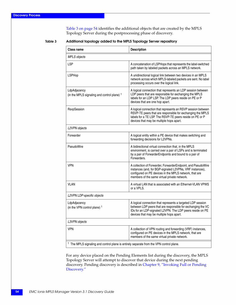
EMC Ionix MPLS Manager Version 3.1 Discovery Guide54
Discovery Process
Table 3 on page 54 identifies the additional objects that are created by the MPLS Topology Server during the postprocessing phase of discovery.
For any device placed on the Pending Elements list during the discovery, the MPLS Topology Server will attempt to discover that device during the next pending discovery. Pending discovery is described in Chapter 9, ”Invoking Full or Pending Discovery.”
Table 3 Additional topology added to the MPLS Topology Server repository
Class name Description
MPLS objects
LSP A concatenation of LSPHops that represents the label-switched path taken by labeled packets across an MPLS network.
LSPHop A unidirectional logical link between two devices in an MPLS network across which MPLS-labeled packets are sent. No label processing occurs over the logical link.
LdpAdjacency(in the MPLS signaling and control plane) 1
A logical connection that represents an LDP session between LDP peers that are responsible for exchanging the MPLS labels for an LDP LSP. The LDP peers reside on PE or P devices that are one hop apart.
RsvpSession A logical connection that represents an RSVP session between RSVP-TE peers that are responsible for exchanging the MPLS labels for a TE LSP. The RSVP-TE peers reside on PE or P devices that may be multiple hops apart.
L2VPN objects
Forwarder A logical entity within a PE device that makes switching and forwarding decisions for L2VPNs.
PseudoWire A bidirectional virtual connection that, in the MPLS environment, is carried over a pair of LSPs and is terminated by a pair of ForwarderEndpoints and bound to a pair of Forwarders.
VPN A collection of Forwarder, ForwarderEndpoint, and PseudoWire instances (and, for BGP-signaled L2VPNs, VRF instances), configured on PE devices in the MPLS network, that are members of the same virtual private network.
VLAN A virtual LAN that is associated with an Ethernet-VLAN VPWS or a VPLS.
L2VPN LDP-specific objects
LdpAdjacency(in the VPN control plane) 1
A logical connection that represents a targeted LDP session between LDP peers that are responsible for exchanging the VC IDs for an LDP-signaled L2VPN. The LDP peers reside on PE devices that may be multiple hops apart.
L3VPN objects
VPN A collection of VPN routing and forwarding (VRF) instances, configured on PE devices in the MPLS network, that are members of the same virtual private network.
1 The MPLS signaling and control plane is entirely separate from the VPN control plane.
Discovery of MPLS Objects 55
4
This chapter describes the MPLS discovery performed by MPLS Manager. It consists of the following sections:
◆ MPLS discovery overview ............................................................................................ 56◆ More about LSPs and LSP discovery........................................................................... 57◆ More about LDP adjacencies and LDP adjacency discovery................................... 61◆ More about RSVP sessions and RSVP session discovery......................................... 62◆ MPLS discovery process................................................................................................ 63
Discovery of MPLSObjects
EMC Ionix MPLS Manager Version 3.1 Discovery Guide56
Discovery of MPLS Objects
MPLS discovery overviewFor MPLS discovery, the MPLS Topology Server component of MPLS Manager is able to discover and model the following MPLS entities:
◆ TE tunnels and TE LSPs
Discovers traffic-engineered tunnels and associates backup or secondary TE LSPs with primary TE LSPs; applicable to TE tunnels that are built on Cisco or Juniper M/T devices.
◆ LDP LSPs
Discovers any combination of TE LSPs and LDP LSPs in the managed network.
◆ Inter-AS LSPs
Discovers multi-stacked-label LDP LSPs that span multiple autonomous systems; applicable to inter-AS LSPs that are built on Juniper M/T devices.
◆ Multi-vendor LSPs
Discovers TE LSPs and LDP LSPs that are built on a mixture of multi-vendor devices.
◆ LSP load balancing
Discovers multi-path load balancing for LDP LSPs on Juniper M/T devices; disabled by default.
◆ LDP adjacencies
Discovers non-targeted LDP adjacencies for Cisco IOS and Juniper devices.
◆ RSVP sessions
Discovers RSVP sessions for Cisco IOS and Juniper M/T devices.
◆ PE and P devices
Discovers PE and P devices that are implemented on any of the P- or PE-capable devices that are supported by MPLS Manager.
◆ CE and multi-VRF CE devices
Discovers traditional CE devices that are implemented on any of the CE-capable devices that are supported by MPLS Manager.
Discovers multi-VRF CE devices that are implemented on any of the multi-VRF CE capable Cisco devices that are supported by MPLS Manager.
All discovery features except LSP load balancing are enabled by default. The enabling parameter for LSP load balancing is “EnableLoadBalancingLSP,” which is described in the EMC Ionix MPLS Manager Configuration Guide.
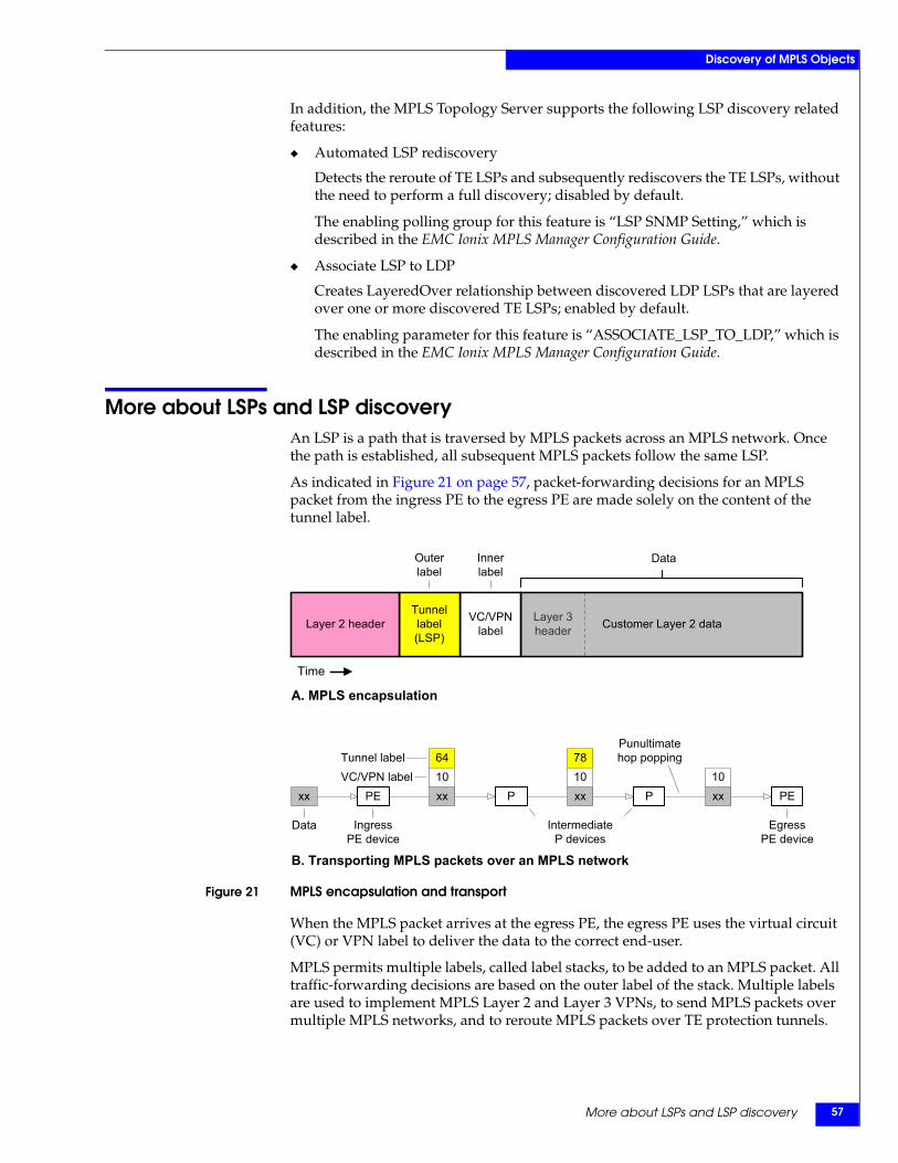
More about LSPs and LSP discovery 57
Discovery of MPLS Objects
In addition, the MPLS Topology Server supports the following LSP discovery related features:
◆ Automated LSP rediscovery
Detects the reroute of TE LSPs and subsequently rediscovers the TE LSPs, without the need to perform a full discovery; disabled by default.
The enabling polling group for this feature is “LSP SNMP Setting,” which is described in the EMC Ionix MPLS Manager Configuration Guide.
◆ Associate LSP to LDP
Creates LayeredOver relationship between discovered LDP LSPs that are layered over one or more discovered TE LSPs; enabled by default.
The enabling parameter for this feature is “ASSOCIATE_LSP_TO_LDP,” which is described in the EMC Ionix MPLS Manager Configuration Guide.
More about LSPs and LSP discoveryAn LSP is a path that is traversed by MPLS packets across an MPLS network. Once the path is established, all subsequent MPLS packets follow the same LSP.
As indicated in Figure 21 on page 57, packet-forwarding decisions for an MPLS packet from the ingress PE to the egress PE are made solely on the content of the tunnel label.
Figure 21 MPLS encapsulation and transport
When the MPLS packet arrives at the egress PE, the egress PE uses the virtual circuit (VC) or VPN label to deliver the data to the correct end-user.
MPLS permits multiple labels, called label stacks, to be added to an MPLS packet. All traffic-forwarding decisions are based on the outer label of the stack. Multiple labels are used to implement MPLS Layer 2 and Layer 3 VPNs, to send MPLS packets over multiple MPLS networks, and to reroute MPLS packets over TE protection tunnels.
A. MPLS encapsulation
Customer Layer 2 dataLayer 3header
VC/VPNlabel
Tunnellabel(LSP)
Layer 2 header
Outerlabel
Innerlabel
Data
Time
xx PE PEP P
B. Transporting MPLS packets over an MPLS network
78
xx10
xx10
IngressPE device
EgressPE device
Data
64
xx10
IntermediateP devices
Punultimatehop poppingTunnel label
VC/VPN label
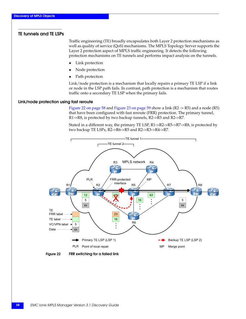
EMC Ionix MPLS Manager Version 3.1 Discovery Guide58
Discovery of MPLS Objects
TE tunnels and TE LSPsTraffic engineering (TE) broadly encapsulates both Layer 2 protection mechanisms as well as quality of service (QoS) mechanisms. The MPLS Topology Server supports the Layer 2 protection aspect of MPLS traffic engineering. It detects the following protection mechanisms on TE tunnels and performs impact analysis on the tunnels.
◆ Link protection
◆ Node protection
◆ Path protection
Link/node protection is a mechanism that locally repairs a primary TE LSP if a link or node in the LSP path fails. In contrast, path protection is a mechanism that routes traffic onto a secondary TE LSP when the primary fails.
Link/node protection using fast rerouteFigure 22 on page 58 and Figure 23 on page 59 show a link (R2 -> R5) and a node (R5) that have been configured with fast reroute (FRR) protection. The primary tunnel, R1->R8, is protected by two backup tunnels, R2->R5 and R2->R7.
Stated in a different way, the primary TE LSP, R1->R2->R5->R7->R8, is protected by two backup TE LSPs, R2->R6->R5 and R2->R3->R4->R7.
Figure 22 FRR switching for a failed link
FRR-protected interface
MP
R1 R2 R5
R6
R7 R8
PLR
MPLS network R4R3
16 42
TEFRR labelTE labelVC/VPN labelData
1623
5xx
16512
xx
TE tunnel 2TE tunnel 1
Point of local repair
Primary TE LSP (LSP 1)
PLR Merge point
Backup TE LSP (LSP 2)
MP
5xx
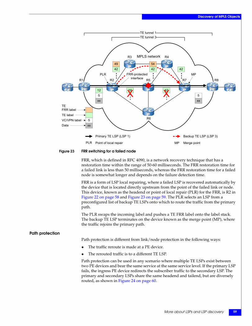
More about LSPs and LSP discovery 59
Discovery of MPLS Objects
Figure 23 FRR switching for a failed node
FRR, which is defined in RFC 4090, is a network recovery technique that has a restoration time within the range of 50-60 milliseconds. The FRR restoration time for a failed link is less than 50 milliseconds, whereas the FRR restoration time for a failed node is somewhat longer and depends on the failure detection time.
FRR is a form of LSP local repairing, where a failed LSP is recovered automatically by the device that is located directly upstream from the point of the failed link or node. This device, known as the headend or point of local repair (PLR) for the FRR, is R2 in Figure 22 on page 58 and Figure 23 on page 59. The PLR selects an LSP from a preconfigured list of backup TE LSPs onto which to route the traffic from the primary path.
The PLR swaps the incoming label and pushes a TE FRR label onto the label stack. The backup TE LSP terminates on the device known as the merge point (MP), where the traffic rejoins the primary path.
Path protectionPath protection is different from link/node protection in the following ways:
◆ The traffic reroute is made at a PE device.
◆ The rerouted traffic is to a different TE LSP.
Path protection can be used in any scenario where multiple TE LSPs exist between two PE devices and bear the same service at the same service level. If the primary LSP fails, the ingress PE device redirects the subscriber traffic to the secondary LSP. The primary and secondary LSPs share the same headend and tailend, but are diversely routed, as shown in Figure 24 on page 60.
R1 R2
R6
R7 R8
PLR MP
MPLS network R4R3
16 42
4249
512
xx5xx
4254
42FRR-protected
interface R5
TE tunnel 3TE tunnel 1
Point of local repair
Primary TE LSP (LSP 1)
PLR Merge point
Backup TE LSP (LSP 3)
MP
TEFRR labelTE labelVC/VPN labelData
5xx
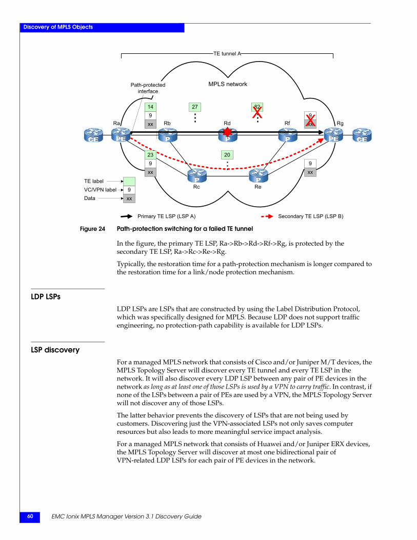
EMC Ionix MPLS Manager Version 3.1 Discovery Guide60
Discovery of MPLS Objects
Figure 24 Path-protection switching for a failed TE tunnel
In the figure, the primary TE LSP, Ra->Rb->Rd->Rf->Rg, is protected by the secondary TE LSP, Ra->Rc->Re->Rg.
Typically, the restoration time for a path-protection mechanism is longer compared to the restoration time for a link/node protection mechanism.
LDP LSPsLDP LSPs are LSPs that are constructed by using the Label Distribution Protocol, which was specifically designed for MPLS. Because LDP does not support traffic engineering, no protection-path capability is available for LDP LSPs.
LSP discoveryFor a managed MPLS network that consists of Cisco and/or Juniper M/T devices, the MPLS Topology Server will discover every TE tunnel and every TE LSP in the network. It will also discover every LDP LSP between any pair of PE devices in the network as long as at least one of those LSPs is used by a VPN to carry traffic. In contrast, if none of the LSPs between a pair of PEs are used by a VPN, the MPLS Topology Server will not discover any of those LSPs.
The latter behavior prevents the discovery of LSPs that are not being used by customers. Discovering just the VPN-associated LSPs not only saves computer resources but also leads to more meaningful service impact analysis.
For a managed MPLS network that consists of Huawei and/or Juniper ERX devices, the MPLS Topology Server will discover at most one bidirectional pair of VPN-related LDP LSPs for each pair of PE devices in the network.
9xxRa Rb Rd Rf Rg
MPLS network
ReRc
27 82
923
xx9xx
20
Path-protected interface
914
xx
TE tunnel A
Primary TE LSP (LSP A) Secondary TE LSP (LSP B)
TE labelVC/VPN labelData
9xx
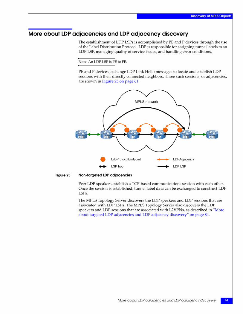
More about LDP adjacencies and LDP adjacency discovery 61
Discovery of MPLS Objects
More about LDP adjacencies and LDP adjacency discoveryThe establishment of LDP LSPs is accomplished by PE and P devices through the use of the Label Distribution Protocol. LDP is responsible for assigning tunnel labels to an LDP LSP, managing quality of service issues, and handling error conditions.
Note: An LDP LSP is PE to PE.
PE and P devices exchange LDP Link Hello messages to locate and establish LDP sessions with their directly connected neighbors. Three such sessions, or adjacencies, are shown in Figure 25 on page 61.
Figure 25 Non-targeted LDP adjacencies
Peer LDP speakers establish a TCP-based communications session with each other. Once the session is established, tunnel label data can be exchanged to construct LDP LSPs.
The MPLS Topology Server discovers the LDP speakers and LDP sessions that are associated with LDP LSPs. The MPLS Topology Server also discovers the LDP speakers and LDP sessions that are associated with L2VPNs, as described in “More about targeted LDP adjacencies and LDP adjacency discovery” on page 84.
MPLS network
LdpProtocolEndpoint
LSP hop LDP LSP
LDPAdjacency
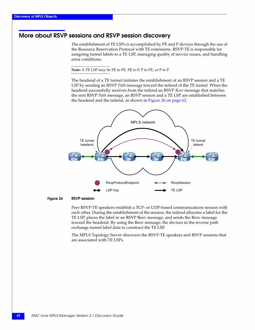
EMC Ionix MPLS Manager Version 3.1 Discovery Guide62
Discovery of MPLS Objects
More about RSVP sessions and RSVP session discoveryThe establishment of TE LSPs is accomplished by PE and P devices through the use of the Resource Reservation Protocol with TE extensions. RSVP-TE is responsible for assigning tunnel labels to a TE LSP, managing quality of service issues, and handling error conditions.
Note: A TE LSP may be PE to PE, PE to P, P to PE, or P to P.
The headend of a TE tunnel initiates the establishment of an RSVP session and a TE LSP by sending an RSVP Path message toward the tailend of the TE tunnel. When the headend successfully receives from the tailend an RSVP Resv message that matches the sent RSVP Path message, an RSVP session and a TE LSP are established between the headend and the tailend, as shown in Figure 26 on page 62.
Figure 26 RSVP session
Peer RSVP-TE speakers establish a TCP- or UDP-based communications session with each other. During the establishment of the session, the tailend allocates a label for the TE LSP, places the label in an RSVP Resv message, and sends the Resv message toward the headend. By using the Resv message, the devices in the reverse path exchange tunnel label data to construct the TE LSP.
The MPLS Topology Server discovers the RSVP-TE speakers and RSVP sessions that are associated with TE LSPs.
TE tunnelheadend
TE tunneltailend
MPLS network
RsvpProtocolEndpoint
LSP hop TE LSP
RsvpSession
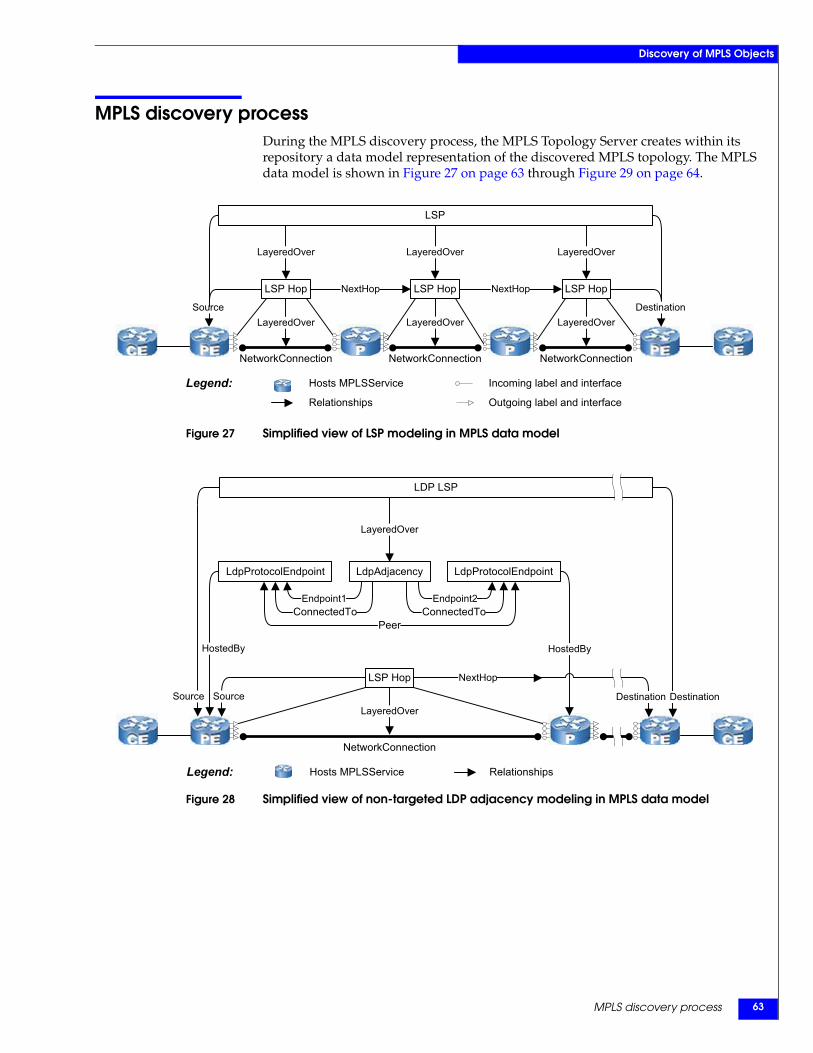
MPLS discovery process 63
Discovery of MPLS Objects
MPLS discovery processDuring the MPLS discovery process, the MPLS Topology Server creates within its repository a data model representation of the discovered MPLS topology. The MPLS data model is shown in Figure 27 on page 63 through Figure 29 on page 64.
Figure 27 Simplified view of LSP modeling in MPLS data model
Figure 28 Simplified view of non-targeted LDP adjacency modeling in MPLS data model
NetworkConnection NetworkConnection NetworkConnection
Legend: Incoming label and interface
Outgoing label and interface
Hosts MPLSService
Relationships
Source
LSP
NextHop NextHop
LayeredOver
LayeredOver
LSP Hop
LayeredOver
LayeredOver
LSP Hop
LayeredOver
LayeredOver
LSP Hop
Destination
NetworkConnection
Legend: Hosts MPLSService Relationships
Source
HostedBy
DestinationLayeredOver
LSP Hop NextHop
Source
HostedBy
Destination
LDP LSP
LdpProtocolEndpoint LdpAdjacency LdpProtocolEndpoint
LayeredOver
Peer
Endpoint1ConnectedTo
Endpoint2ConnectedTo
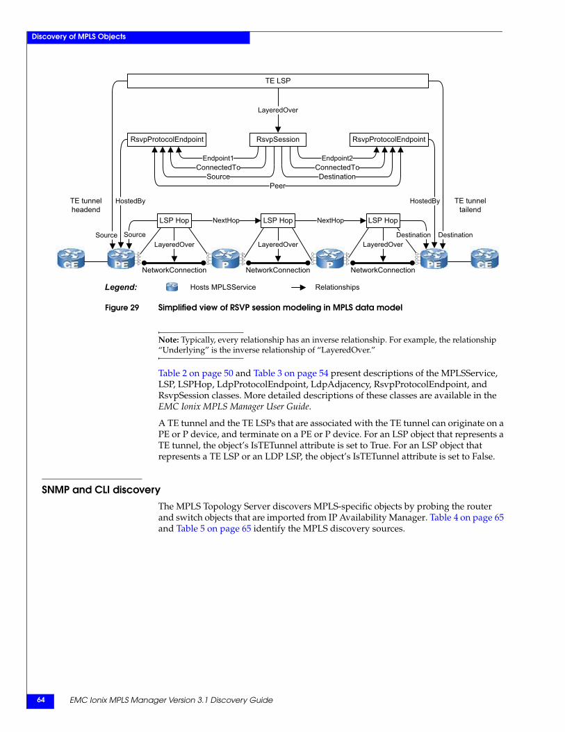
EMC Ionix MPLS Manager Version 3.1 Discovery Guide64
Discovery of MPLS Objects
Figure 29 Simplified view of RSVP session modeling in MPLS data model
Note: Typically, every relationship has an inverse relationship. For example, the relationship “Underlying” is the inverse relationship of “LayeredOver.”
Table 2 on page 50 and Table 3 on page 54 present descriptions of the MPLSService, LSP, LSPHop, LdpProtocolEndpoint, LdpAdjacency, RsvpProtocolEndpoint, and RsvpSession classes. More detailed descriptions of these classes are available in the EMC Ionix MPLS Manager User Guide.
A TE tunnel and the TE LSPs that are associated with the TE tunnel can originate on a PE or P device, and terminate on a PE or P device. For an LSP object that represents a TE tunnel, the object’s IsTETunnel attribute is set to True. For an LSP object that represents a TE LSP or an LDP LSP, the object’s IsTETunnel attribute is set to False.
SNMP and CLI discoveryThe MPLS Topology Server discovers MPLS-specific objects by probing the router and switch objects that are imported from IP Availability Manager. Table 4 on page 65 and Table 5 on page 65 identify the MPLS discovery sources.
Legend: Hosts MPLSService Relationships
TE LSP
RsvpProtocolEndpoint
Destination
Peer
Endpoint1
SourceConnectedTo
Source
HostedByTE tunnelheadend
TE tunneltailend
RsvpProtocolEndpoint
HostedBy
LayeredOver
Endpoint2
DestinationConnectedTo
NextHop NextHopLSP Hop LSP Hop LSP Hop
NetworkConnection NetworkConnection NetworkConnection
Source DestinationLayeredOver LayeredOver LayeredOver
RsvpSession
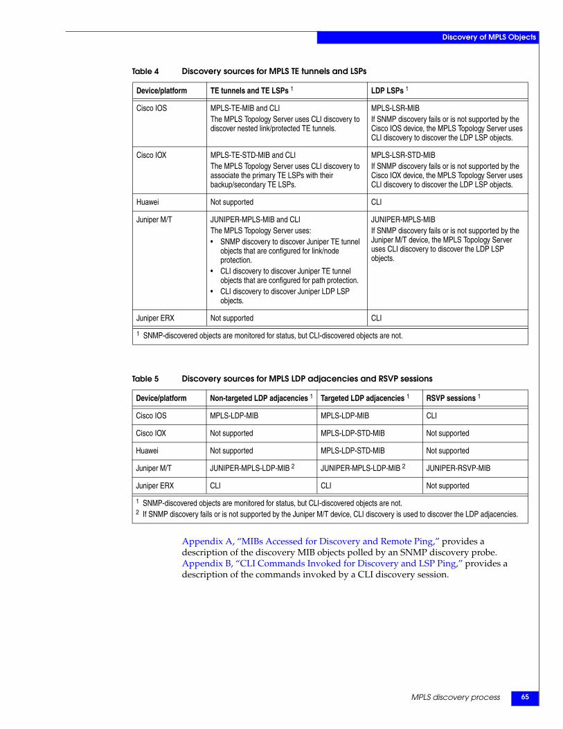
MPLS discovery process 65
Discovery of MPLS Objects
Appendix A, “MIBs Accessed for Discovery and Remote Ping,” provides a description of the discovery MIB objects polled by an SNMP discovery probe. Appendix B, “CLI Commands Invoked for Discovery and LSP Ping,” provides a description of the commands invoked by a CLI discovery session.
Table 4 Discovery sources for MPLS TE tunnels and LSPs
Device/platform TE tunnels and TE LSPs 1 LDP LSPs 1
Cisco IOS MPLS-TE-MIB and CLIThe MPLS Topology Server uses CLI discovery to discover nested link/protected TE tunnels.
MPLS-LSR-MIBIf SNMP discovery fails or is not supported by the Cisco IOS device, the MPLS Topology Server uses CLI discovery to discover the LDP LSP objects.
Cisco IOX MPLS-TE-STD-MIB and CLIThe MPLS Topology Server uses CLI discovery to associate the primary TE LSPs with their backup/secondary TE LSPs.
MPLS-LSR-STD-MIBIf SNMP discovery fails or is not supported by the Cisco IOX device, the MPLS Topology Server uses CLI discovery to discover the LDP LSP objects.
Huawei Not supported CLI
Juniper M/T JUNIPER-MPLS-MIB and CLIThe MPLS Topology Server uses:• SNMP discovery to discover Juniper TE tunnel
objects that are configured for link/node protection.
• CLI discovery to discover Juniper TE tunnel objects that are configured for path protection.
• CLI discovery to discover Juniper LDP LSP objects.
JUNIPER-MPLS-MIBIf SNMP discovery fails or is not supported by the Juniper M/T device, the MPLS Topology Server uses CLI discovery to discover the LDP LSP objects.
Juniper ERX Not supported CLI
1 SNMP-discovered objects are monitored for status, but CLI-discovered objects are not.
Table 5 Discovery sources for MPLS LDP adjacencies and RSVP sessions
Device/platform Non-targeted LDP adjacencies 1 Targeted LDP adjacencies 1 RSVP sessions 1
Cisco IOS MPLS-LDP-MIB MPLS-LDP-MIB CLI
Cisco IOX Not supported MPLS-LDP-STD-MIB Not supported
Huawei Not supported MPLS-LDP-STD-MIB Not supported
Juniper M/T JUNIPER-MPLS-LDP-MIB 2 JUNIPER-MPLS-LDP-MIB 2 JUNIPER-RSVP-MIB
Juniper ERX CLI CLI Not supported
1 SNMP-discovered objects are monitored for status, but CLI-discovered objects are not.2 If SNMP discovery fails or is not supported by the Juniper M/T device, CLI discovery is used to discover the LDP adjacencies.
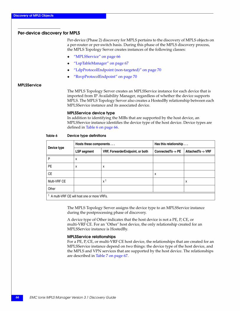
EMC Ionix MPLS Manager Version 3.1 Discovery Guide66
Discovery of MPLS Objects
Per-device discovery for MPLSPer-device (Phase 2) discovery for MPLS pertains to the discovery of MPLS objects on a per-router or per-switch basis. During this phase of the MPLS discovery process, the MPLS Topology Server creates instances of the following classes:
◆ “MPLSService” on page 66
◆ “LspTableManager” on page 67
◆ “LdpProtocolEndpoint (non-targeted)” on page 70
◆ “RsvpProtocolEndpoint” on page 70
MPLSServiceThe MPLS Topology Server creates an MPLSService instance for each device that is imported from IP Availability Manager, regardless of whether the device supports MPLS. The MPLS Topology Server also creates a HostedBy relationship between each MPLSService instance and its associated device.
MPLSService device typeIn addition to identifying the MIBs that are supported by the host device, an MPLSService instance identifies the device type of the host device. Device types are defined in Table 6 on page 66.
The MPLS Topology Server assigns the device type to an MPLSService instance during the postprocessing phase of discovery.
A device type of Other indicates that the host device is not a PE, P, CE, or multi-VRF CE. For an "Other" host device, the only relationship created for an MPLSService instance is HostedBy.
MPLSService relationshipsFor a PE, P, CE, or multi-VRF CE host device, the relationships that are created for an MPLSService instance depend on two things: the device type of the host device, and the MPLS and VPN services that are supported by the host device. The relationships are described in Table 7 on page 67.
Table 6 Device type definitions
Device typeHosts these components . . . Has this relationship . . .
LSP segment VRF, ForwarderEndpoint, or both ConnectedTo -> PE AttachedTo -> VRF
P x
PE x x
CE x
Multi-VRF CE x 1 x
Other
1 A multi-VRF CE will host one or more VRFs.
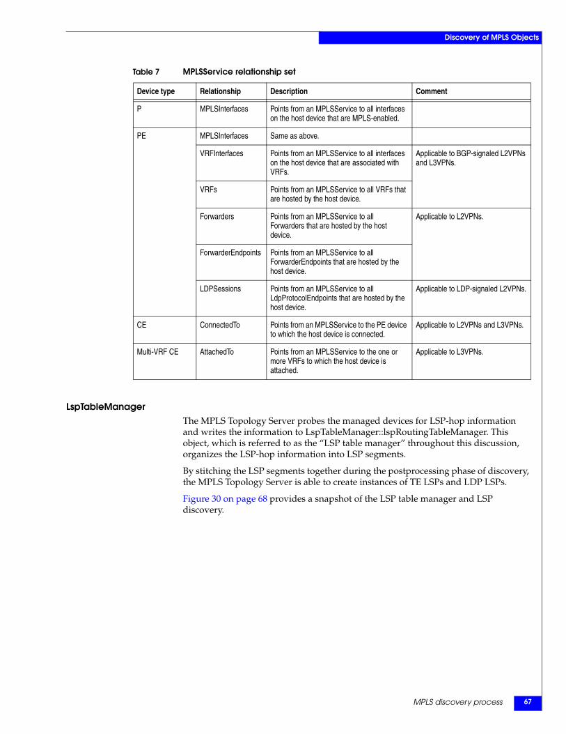
MPLS discovery process 67
Discovery of MPLS Objects
LspTableManagerThe MPLS Topology Server probes the managed devices for LSP-hop information and writes the information to LspTableManager::lspRoutingTableManager. This object, which is referred to as the “LSP table manager” throughout this discussion, organizes the LSP-hop information into LSP segments.
By stitching the LSP segments together during the postprocessing phase of discovery, the MPLS Topology Server is able to create instances of TE LSPs and LDP LSPs.
Figure 30 on page 68 provides a snapshot of the LSP table manager and LSP discovery.
Table 7 MPLSService relationship set
Device type Relationship Description Comment
P MPLSInterfaces Points from an MPLSService to all interfaces on the host device that are MPLS-enabled.
PE MPLSInterfaces Same as above.
VRFInterfaces Points from an MPLSService to all interfaces on the host device that are associated with VRFs.
Applicable to BGP-signaled L2VPNs and L3VPNs.
VRFs Points from an MPLSService to all VRFs that are hosted by the host device.
Forwarders Points from an MPLSService to all Forwarders that are hosted by the host device.
Applicable to L2VPNs.
ForwarderEndpoints Points from an MPLSService to all ForwarderEndpoints that are hosted by the host device.
LDPSessions Points from an MPLSService to all LdpProtocolEndpoints that are hosted by the host device.
Applicable to LDP-signaled L2VPNs.
CE ConnectedTo Points from an MPLSService to the PE device to which the host device is connected.
Applicable to L2VPNs and L3VPNs.
Multi-VRF CE AttachedTo Points from an MPLSService to the one or more VRFs to which the host device is attached.
Applicable to L3VPNs.
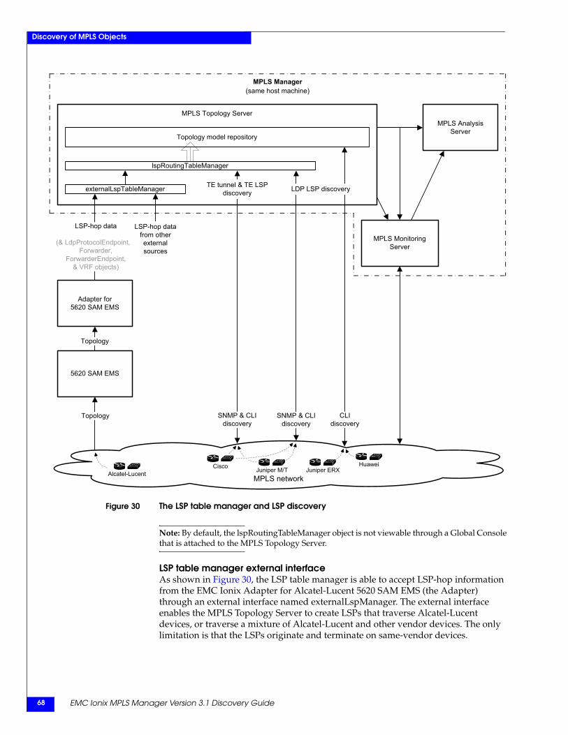
EMC Ionix MPLS Manager Version 3.1 Discovery Guide68
Discovery of MPLS Objects
Figure 30 The LSP table manager and LSP discovery
Note: By default, the lspRoutingTableManager object is not viewable through a Global Console that is attached to the MPLS Topology Server.
LSP table manager external interfaceAs shown in Figure 30, the LSP table manager is able to accept LSP-hop information from the EMC Ionix Adapter for Alcatel-Lucent 5620 SAM EMS (the Adapter) through an external interface named externalLspManager. The external interface enables the MPLS Topology Server to create LSPs that traverse Alcatel-Lucent devices, or traverse a mixture of Alcatel-Lucent and other vendor devices. The only limitation is that the LSPs originate and terminate on same-vendor devices.
MPLS network
MPLS Monitoring Server
MPLS Topology ServerMPLS Analysis
Server
MPLS Manager(same host machine)
Topology model repository
Topology
5620 SAM EMS
Topology
LSP-hop data
(& LdpProtocolEndpoint, xForwarder,
ForwarderEndpoint,& VRF objects)
Alcatel-Lucent
Adapter for5620 SAM EMS
lspRoutingTableManager
externalLspTableManager
HuaweiJuniper ERXJuniper M/TCisco
SNMP & CLIdiscovery
TE tunnel & TE LSPdiscovery
CLIdiscovery
SNMP & CLIdiscovery
LDP LSP discovery
LSP-hop data from otherexternalsources
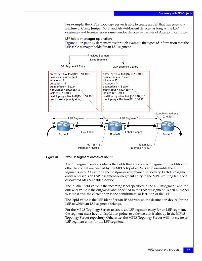
MPLS discovery process 69
Discovery of MPLS Objects
For example, the MPLS Topology Server is able to create an LSP that traverses any mixture of Cisco, Juniper M/T, and Alcatel-Lucent devices, as long as the LSP originates and terminates on same-vendor devices, say a pair of Alcatel-Lucent PEs.
LSP table manager operationFigure 31 on page 69 demonstrates through example the types of information that the LSP table manager holds for an LSP segment.
Figure 31 Two LSP segment entries of an LSP
An LSP segment entry contains the fields that are shown in Figure 31, in addition to other fields that are needed by the MPLS Topology Server to assemble the LSP segments into LSPs during the postprocessing phase of discovery. Each LSP segment entry represents an LSP insegment-outsegment entry in the MPLS routing table of a discovered MPLS-enabled device.
The inLabel field value is the incoming label specified in the LSP insegment, and the outLabel value is the outgoing label specified in the LSP outsegment. When outLabel is set to 0 or 3, the current hop is the penultimate, or last, hop of the LSP.
The lspId value is the LSP identifier (an IP address) on the destination device for the LSP to which an LSP segment belongs.
For the MPLS Topology Server to create an LSP segment entry for an LSP segment, the segment must have an lspId that points to a device that is already in the MPLS Topology Server repository. Otherwise, the MPLS Topology Server will not create an LSP segment entry for the LSP segment.
192.168.1.7Interface = “Se0/1”
Loopback address:10.10.10.1
entryKey = RouterA|12|10.10.10.1|deviceName = RouterAinLabel = 12outLabel = 15outInterface = “Se0/0”nextHopIp = 192.168.1.5lspId = 10.10.10.1nextHopKey = RouterB|15|10.10.10.1|preHopKey = (empty string)...
entryKey = RouterB|15|10.10.10.1|deviceName = RouterBinLabel = 15outLabel = 3outInterface = “Se0/0”nextHopIp = 192.168.1.7lspId = 10.10.10.1nextHopKey = RouterC|3|10.10.10.1|preHopKey = RouterA|12|10.10.10.1|...
RouterB
192.168.1.5Interface = “Se0/1”
3151512
LSP Segment 2LSP Segment 1
LSP Segment 1 Entry LSP Segment 2 Entry
Next SegmentPrevious Segment
First Label Label “Popped”RouterA RouterC
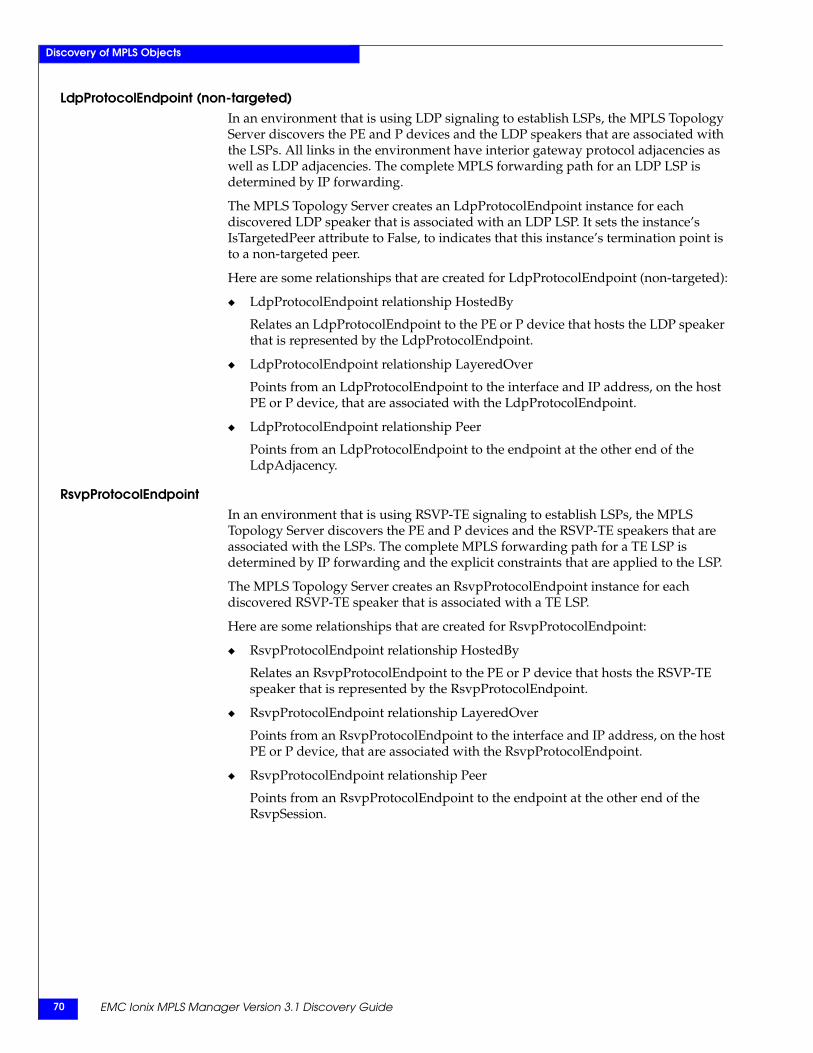
EMC Ionix MPLS Manager Version 3.1 Discovery Guide70
Discovery of MPLS Objects
LdpProtocolEndpoint (non-targeted)In an environment that is using LDP signaling to establish LSPs, the MPLS Topology Server discovers the PE and P devices and the LDP speakers that are associated with the LSPs. All links in the environment have interior gateway protocol adjacencies as well as LDP adjacencies. The complete MPLS forwarding path for an LDP LSP is determined by IP forwarding.
The MPLS Topology Server creates an LdpProtocolEndpoint instance for each discovered LDP speaker that is associated with an LDP LSP. It sets the instance’s IsTargetedPeer attribute to False, to indicates that this instance’s termination point is to a non-targeted peer.
Here are some relationships that are created for LdpProtocolEndpoint (non-targeted):
◆ LdpProtocolEndpoint relationship HostedBy
Relates an LdpProtocolEndpoint to the PE or P device that hosts the LDP speaker that is represented by the LdpProtocolEndpoint.
◆ LdpProtocolEndpoint relationship LayeredOver
Points from an LdpProtocolEndpoint to the interface and IP address, on the host PE or P device, that are associated with the LdpProtocolEndpoint.
◆ LdpProtocolEndpoint relationship Peer
Points from an LdpProtocolEndpoint to the endpoint at the other end of the LdpAdjacency.
RsvpProtocolEndpointIn an environment that is using RSVP-TE signaling to establish LSPs, the MPLS Topology Server discovers the PE and P devices and the RSVP-TE speakers that are associated with the LSPs. The complete MPLS forwarding path for a TE LSP is determined by IP forwarding and the explicit constraints that are applied to the LSP.
The MPLS Topology Server creates an RsvpProtocolEndpoint instance for each discovered RSVP-TE speaker that is associated with a TE LSP.
Here are some relationships that are created for RsvpProtocolEndpoint:
◆ RsvpProtocolEndpoint relationship HostedBy
Relates an RsvpProtocolEndpoint to the PE or P device that hosts the RSVP-TE speaker that is represented by the RsvpProtocolEndpoint.
◆ RsvpProtocolEndpoint relationship LayeredOver
Points from an RsvpProtocolEndpoint to the interface and IP address, on the host PE or P device, that are associated with the RsvpProtocolEndpoint.
◆ RsvpProtocolEndpoint relationship Peer
Points from an RsvpProtocolEndpoint to the endpoint at the other end of the RsvpSession.
MPLS discovery process 71
Discovery of MPLS Objects
Post-processing discovery for MPLSDuring this phase (Phase 3) of the MPLS discovery process, which starts after per-device discovery completes, the MPLS Topology Server creates instances of the following classes by combining the information that is collected during the per-device MPLS discovery:
◆ “LSP” on page 71
◆ “LSPHop” on page 74
◆ “LdpAdjacency (non-targeted)” on page 74
◆ “RsvpSession” on page 75
For LSP discovery on Cisco or Juniper M/T devices, the MPLS Topology Server uses the LSP table manager to create the LSP and LSPHop instances.
For LSP discovery on Huawei or Juniper ERX devices, the MPLS Topology Server uses similar software to create the LSP and LSPHop instances. That software employs the LSP discovery method that was used in MPLS Management Suite 2.1: Create LSPInSegment and LSPOutSegment objects, and from those objects, create the LSP and LSPHop objects.
LSPThe MPLS Topology Server uses the “LSP” class to create instances of the discovered TE tunnels, TE LSPs, and LDP LSPs. For an LSP instance that represents a TE LSP or an LDP LSP, the MPLS Topology Server sets the instance’s IsTETunnel attribute to False.
For an LSP instance that represents a TE tunnel, that is, represents a primary TE LSP and one or more backup/secondary TE LSPs, the MPLS Topology Server sets the instance’s IsTETunnel attribute to True. The instance can be thought of as an object that is protected by a primary TE LSP and the one or more TE LSPs that back up the primary. As such, a TE tunnel instance has no LSP hops and is not directly associated with any interfaces.
LSP creationThe MPLS Topology Server scans all of its LSP segment entries in the LSP table manager and examines their entryKey and nextHopKey values. For each LSP segment entry that has an entryKey value that does not appear in the nextHopKey field of any other LSP segment entry, the MPLS Topology Server proceeds as follows:
◆ Examines the deviceName and lspId values for the LSP segment entry.
◆ Creates an LSP instance between the device that is identified by the deviceName (the source device for the LSP) and the device identified by the lspId (the destination device for the LSP). The name of the destination device is obtained by traversing the HostedBy relationship of the lspId IP object to the device.
Because the incoming interface is not included in an LSP segment entry, the MPLS Topology Server identifies the interface through the network connection between the outgoing interface of the previous segment and the next hop IP. In Figure 31 on page 69, for example, the incoming interface on RouterB can be obtained through the network connection between the Se0/0 interface of RouterA and the next hop IP 192.168.1.5 of RouterB, both of which are saved in the first LSP segment entry.
EMC Ionix MPLS Manager Version 3.1 Discovery Guide72
Discovery of MPLS Objects
LSP naming convention for TE tunnelsThe MPLS Topology Server uses the following convention to name a Cisco-based TE tunnel:
TETunnel-<tunnel name>/<device name>_<tunnel ID>
For example:TETunnel-dev-VPLS5-t579/dev-Vpls5_579
The MPLS Topology Server uses the following convention to name a Cisco-based primary or backup/secondary TE LSP:
<tunnel name>_Primary|Secondary
For example:dev-VPLS5-t579_Primary
For discovered TE tunnels and TE LSPs that are built on Juniper M/T devices, the MPLS Topology Server uses the tunnel names that are available in the JUNIPER-MPLS-MIB. Because no tunnel IDs are available in the JUNIPER-MPLS-MIB, no tunnel ID appears in the name of a TE tunnel that is discovered on a Juniper M/T device; for example:
TETunnel-QA-MPLSp8-to-DEV-VPLS0/qa-MPLSp8
The EMC Ionix MPLS Manager User Guide describes in detail the naming formats that are used to create MPLS and VPN object names.
LSP naming convention for LDP LSPsThe MPLS Topology Server uses the following convention to name LDP LSPs:
LSP-<source device name>-><destination device name>/<LSP identifier>
For example:
LSP-dev-MPLSp5->dev-Vpls9/192.168.19.1
LSP relationshipsHere are some relationships that are computed for TE LSPs and LDP LSPs:
◆ LSP relationship Source
Points from an LSP to the source PE or P device for the LSP.
◆ LSP relationship Destination
Points from an LSP to the destination PE or P device for the LSP.
◆ LSP relationship LayeredOver
Points from an LSP to all LSPHops that belong to the LSP. Also points to the outgoing and incoming interfaces that are associated with the LSPHops that belong to the LSP.
Here are three additional relationships that are computed for TE tunnels:
◆ TE tunnel relationship ProtectedBy
For a link-protected and/or node-protected tunnel, points from the TE tunnel (IsTETunnel=True) to the primary TE LSP and the one or more backup TE tunnels that protect this tunnel.
For a path-protected tunnel, points from the TE tunnel (IsTETunnel=True) to the primary TE LSP and the one or more secondary TE LSPs that protect this tunnel.
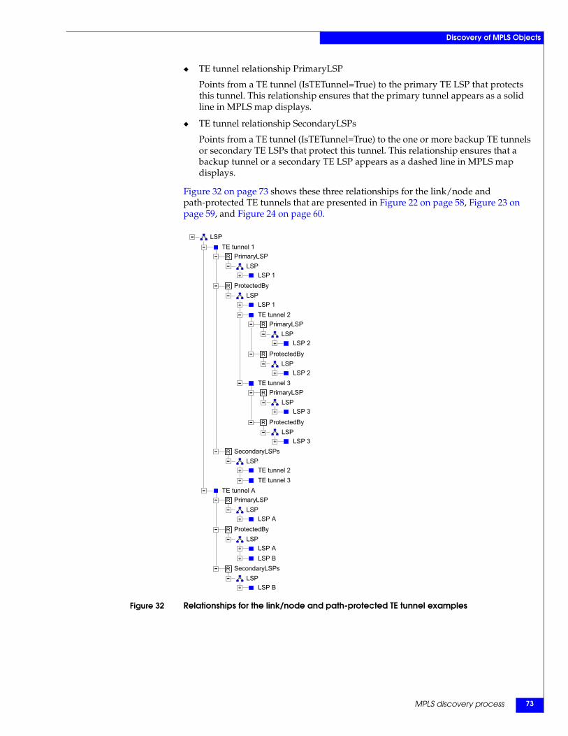
MPLS discovery process 73
Discovery of MPLS Objects
◆ TE tunnel relationship PrimaryLSP
Points from a TE tunnel (IsTETunnel=True) to the primary TE LSP that protects this tunnel. This relationship ensures that the primary tunnel appears as a solid line in MPLS map displays.
◆ TE tunnel relationship SecondaryLSPs
Points from a TE tunnel (IsTETunnel=True) to the one or more backup TE tunnels or secondary TE LSPs that protect this tunnel. This relationship ensures that a backup tunnel or a secondary TE LSP appears as a dashed line in MPLS map displays.
Figure 32 on page 73 shows these three relationships for the link/node and path-protected TE tunnels that are presented in Figure 22 on page 58, Figure 23 on page 59, and Figure 24 on page 60.
Figure 32 Relationships for the link/node and path-protected TE tunnel examples
LSP 2
PrimaryLSPLSP
LSP 2
R ProtectedByLSP
PrimaryLSPLSP
LSP 3
TE tunnel 3
ProtectedByLSP
R
R
TE tunnel APrimaryLSP
LSPLSP A
LSP
-TE tunnel 1
PrimaryLSPLSP
LSP 1ProtectedBy
LSPLSP 1TE tunnel 2
LSP 3SecondaryLSPs
LSPTE tunnel 2TE tunnel 3
ProtectedByLSP
LSP ALSP B
SecondaryLSPsLSP
LSP B
-+
R
-
+
+
-
- R
-
-
-R
-+
-
-R
- R
-+
+
+
--
--
- R-
--
+
-+
+
- R
-
-
+
+
EMC Ionix MPLS Manager Version 3.1 Discovery Guide74
Discovery of MPLS Objects
LSP rediscoveryAfter LSP discovery, MPLS Manager monitors the TE tunnels, TE LSPs, and LDP LSPs that are built on Cisco or Juniper M/T devices. If MPLS Manager detects that LSP rerouting has occurred (applicable to TE LSPs only), it initiates rediscovery of the rerouted LSP. LSP monitoring and rediscovery are controlled by the LSP polling group in the Polling and Thresholds Console, as explained in the EMC Ionix MPLS Manager Configuration Guide.
LSPHopFor each TE LSP or LDP LSP instance that the MPLS Topology Server creates, the MPLS Topology Server also creates the LSPHop instances along the path of the LSP. It starts with the source LSP segment for the LSP and uses the nextHopKey value to create the LSPHops from the LSP source to the LSP destination, hop by hop.
If an LSPHop is the first one for an LSP, the MPLS Topology Server creates the Source relationship between that LSPHop and the source device for the LSP. If an LSPHop is the last one for an LSP, the MPLS Topology Server creates the Destination relationship between that LSPHop and the destination device for the LSP.
Here are some other relationships that are computed for LSPHops:
◆ LSPHop relationship LayeredOver
Points from an LSPHop to the network connection that is underlying the LSPHop.
◆ LSPHop relationship Underlying
Points from an LSPHop to the LSP to which the LSPHop belongs.
◆ LSPHop relationship NextHop
Points from an LSPHop to the next LSPHop along the path of an LSP. This relationship is computed only for an LSPHop that is not the last hop in the path of an LSP.
◆ LSPHop relationship PreviousHop
Points from an LSPHop to the previous LSPHop along the path of an LSP. This relationship is computed only for an LSPHop that is not the first hop in the path of an LSP.
LdpAdjacency (non-targeted)In an environment that is using LDP signaling to establish LSPs, the MPLS Topology Server matches various attributes (LocalAddress, PeerAddress) that are associated with the LdpProtocolEndpoints that are discovered on different PE and P devices, and creates an LdpAdjacency instance for each complementary match. the MPLS Topology Server sets each instance’s isTargeted attribute to False, to indicates that this LDP session is not targeted.
An LdpAdjacency is ConnectedTo two LdpProtocolEndpoints, where one LdpProtocolEndpoint is HostedBy one PE or P device, and the second is HostedBy a peering PE or P device. The LdpAdjacency provides a bidirectional signaling path through which the two directly connected peering devices exchange MPLS label information for the purpose of constructing, maintaining, or deleting LDP LSPs.
MPLS discovery process 75
Discovery of MPLS Objects
Here are some other relationships that are computed for LdpAdjacency (non-targeted):
◆ LdpAdjacency relationship Endpoint1
Points from an LdpAdjacency to the LdpProtocolEndpoint that has the lower IP address of the two endpoints that are associated with the LdpAdjacency.
◆ LdpAdjacency relationship Endpoint2
Points from an LdpAdjacency to the LdpProtocolEndpoint that has the higher IP address of the two endpoints that are associated with the LdpAdjacency.
◆ LdpAdjacency relationship Underlying
Points from an LdpAdjacency to the LDP LSP that is associated with the LdpAdjacency.
RsvpSessionIn an environment that is using RSVP-TE signaling to establish LSPs, the MPLS Topology Server matches various attributes (LocalAddress, FromIP, ToIP) that are associated with the RsvpProtocolEndpoints that are discovered on different PE and P devices, and creates an RsvpSession instance for each complementary match.
An RsvpSession is ConnectedTo two RsvpProtocolEndpoints, where one RsvpProtocolEndpoint is HostedBy one PE or P device, and the second is HostedBy a peering PE or P device. The RsvpSession provides a bidirectional signaling path through which the two peering devices exchange MPLS label information for the purpose of constructing, maintaining, or deleting TE LSPs.
Here are some other relationships that are computed for RsvpSession:
◆ RsvpSession relationship Endpoint1
Points from an RsvpSession to the RsvpProtocolEndpoint that represents the source RSVP-TE speaker for the session.
◆ RsvpSession relationship Endpoint2
Points from an RsvpSession to the RsvpProtocolEndpoint that represents the destination RSVP-TE speaker for the session.
◆ RsvpSession relationship Source
Same as Endpoint1.
◆ RsvpSession relationship Destination
Same as Endpoint2.
◆ RsvpSession relationship Underlying
Points from an RsvpSession to the TE LSP that is associated with the session.
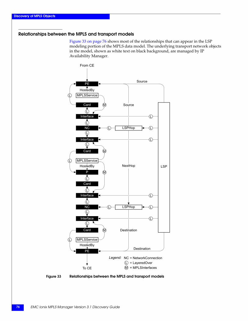
EMC Ionix MPLS Manager Version 3.1 Discovery Guide76
Discovery of MPLS Objects
Relationships between the MPLS and transport modelsFigure 33 on page 76 shows most of the relationships that can appear in the LSP modeling portion of the MPLS data model. The underlying transport network objects in the model, shown as white text on black background, are managed by IP Availability Manager.
Figure 33 Relationships between the MPLS and transport models
HostedByMPLSService
PE
Interface
Card
L
L
Interface
Card
NC
L
L
HostedByMPLSService
P
Interface
Card
L
L
HostedBy
PE
Interface
Card
NC
L
L
L
L
L
L
M
L
L
M
L
Source
L L
MPLSService
LSP
Source
Destination
M
LSPHop
L
LSPHop
NextHop
L
L
Destination
From CE
To CE
= NetworkConnectionL = LayeredOverM = MPLSInterfaces
NCLegend:
M

Discovery of L2VPN Objects 77
5
This chapter describes the L2VPN discovery performed by MPLS Manager. It consists of the following sections:
◆ L2VPN discovery overview.......................................................................................... 78◆ More about L2VPNs and L2VPN discovery .............................................................. 78◆ More about targeted LDP adjacencies and LDP adjacency discovery ................... 84◆ L2VPN discovery process ............................................................................................. 85
Discovery of L2VPNObjects
EMC Ionix MPLS Manager Version 3.1 Discovery Guide78
Discovery of L2VPN Objects
L2VPN discovery overviewFor L2VPN discovery, the MPLS Topology Server component of MPLS Manager is able to discover and model the following MPLS Layer 2 VPN entities:
◆ LDP-signaled L2VPNs
This L2VPN uses Label Distribution Protocol (LDP) signaling to set up and maintain the pseudowires between PE devices in an MPLS network.
◆ BGP-signaled L2VPNs
This L2VPN uses Multiprotocol Border Gateway Protocol (MBGP) signaling to set up and maintain the pseudowires between PE devices in an MPLS network.
◆ VPWS
Virtual Private Wire Service, also known as point-to-point L2VPN, is a technology that uses a pseudowire to emulate a point-to-point circuit across an MPLS network.
◆ VPLS
Virtual Private LAN Service, also known as point-to-multipoint L2VPN, is a technology that uses a full mesh of pseudowires to emulate a LAN across an MPLS network.
Although L2VPN discovery is enabled by default, the MPLS Topology Server requires a Level 2 VPN feature license for the discovery of VPWS and VPLS L2VPNs. The EMC Smarts System Administration Guide provides information about licensing.
More about L2VPNs and L2VPN discoveryL2VPNs are provider-provisioned Layer 2 VPNs that extend the customer’s Layer 2 connectivity through an MPLS network. They do so by emulating different types of traditional data-link layer protocols, including Ethernet, Frame Relay, ATM, and others.
Like L3VPNs, L2VPNs depend entirely on the PE devices. Unlike L3VPNs, L2VPNs do not require that the PE devices participate in the customer’s routing algorithms. The latter statement means that a customer may run any type of Layer 3 protocol between sites, including IP.
An L2VPN may be implemented as a VPWS or a VPLS, where a VPWS provides point-to-point connectivity between two sites, and a VPLS provides point-to-multipoint connectivity between multiple sites. The control plane for either implementation may use LDP or BGP.
The L2VPN data plane is based on the pseudowire, which represents two virtual circuits between a pair of PE devices that are participating in an L2VPN. One virtual circuit is carried over an outgoing LSP, and the other is carried over an incoming LSP. Together, the two virtual circuits provide bidirectional communication for a customer.
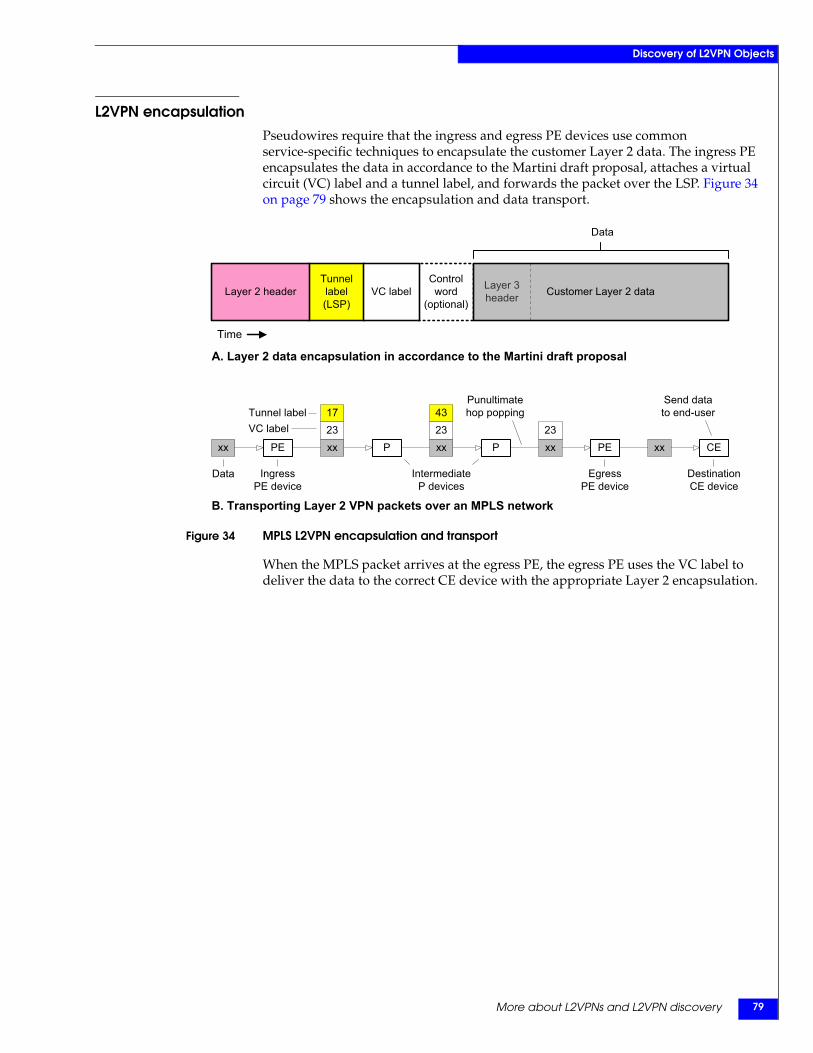
More about L2VPNs and L2VPN discovery 79
Discovery of L2VPN Objects
L2VPN encapsulationPseudowires require that the ingress and egress PE devices use common service-specific techniques to encapsulate the customer Layer 2 data. The ingress PE encapsulates the data in accordance to the Martini draft proposal, attaches a virtual circuit (VC) label and a tunnel label, and forwards the packet over the LSP. Figure 34 on page 79 shows the encapsulation and data transport.
Figure 34 MPLS L2VPN encapsulation and transport
When the MPLS packet arrives at the egress PE, the egress PE uses the VC label to deliver the data to the correct CE device with the appropriate Layer 2 encapsulation.
Control word
(optional)
Tunnellabel(LSP)
Layer 2 header VC label Customer Layer 2 dataLayer 3header
Data
Time
CExx PE PEP P
IngressPE device
EgressPE device
Data
Punultimatehop poppingTunnel label
xx
IntermediateP devices
DestinationCE device
VC label17
xx23
43
xx23
xx23
Send datato end-user
A. Layer 2 data encapsulation in accordance to the Martini draft proposal
B. Transporting Layer 2 VPN packets over an MPLS network
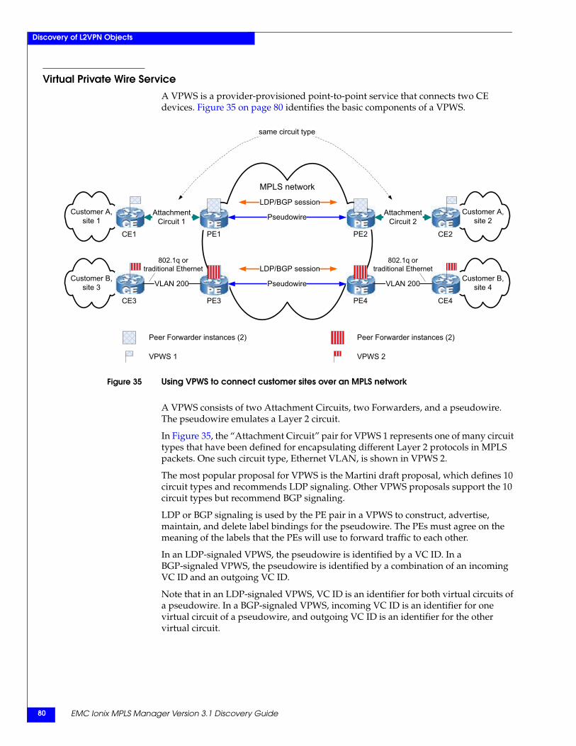
EMC Ionix MPLS Manager Version 3.1 Discovery Guide80
Discovery of L2VPN Objects
Virtual Private Wire ServiceA VPWS is a provider-provisioned point-to-point service that connects two CE devices. Figure 35 on page 80 identifies the basic components of a VPWS.
Figure 35 Using VPWS to connect customer sites over an MPLS network
A VPWS consists of two Attachment Circuits, two Forwarders, and a pseudowire. The pseudowire emulates a Layer 2 circuit.
In Figure 35, the “Attachment Circuit” pair for VPWS 1 represents one of many circuit types that have been defined for encapsulating different Layer 2 protocols in MPLS packets. One such circuit type, Ethernet VLAN, is shown in VPWS 2.
The most popular proposal for VPWS is the Martini draft proposal, which defines 10 circuit types and recommends LDP signaling. Other VPWS proposals support the 10 circuit types but recommend BGP signaling.
LDP or BGP signaling is used by the PE pair in a VPWS to construct, advertise, maintain, and delete label bindings for the pseudowire. The PEs must agree on the meaning of the labels that the PEs will use to forward traffic to each other.
In an LDP-signaled VPWS, the pseudowire is identified by a VC ID. In a BGP-signaled VPWS, the pseudowire is identified by a combination of an incoming VC ID and an outgoing VC ID.
Note that in an LDP-signaled VPWS, VC ID is an identifier for both virtual circuits of a pseudowire. In a BGP-signaled VPWS, incoming VC ID is an identifier for one virtual circuit of a pseudowire, and outgoing VC ID is an identifier for the other virtual circuit.
MPLS network
Customer B,site 4
CE4
Customer B, site 3
CE3
LDP/BGP session
PE3 PE4
Pseudowire VLAN 200VLAN 200
Customer A,site 2
CE2
Customer A, site 1
CE1
LDP/BGP session
PE1 PE2
Pseudowire AttachmentCircuit 2
802.1q ortraditional Ethernet
802.1q ortraditional Ethernet
AttachmentCircuit 1
Peer Forwarder instances (2)Peer Forwarder instances (2)
VPWS 2VPWS 1
same circuit type
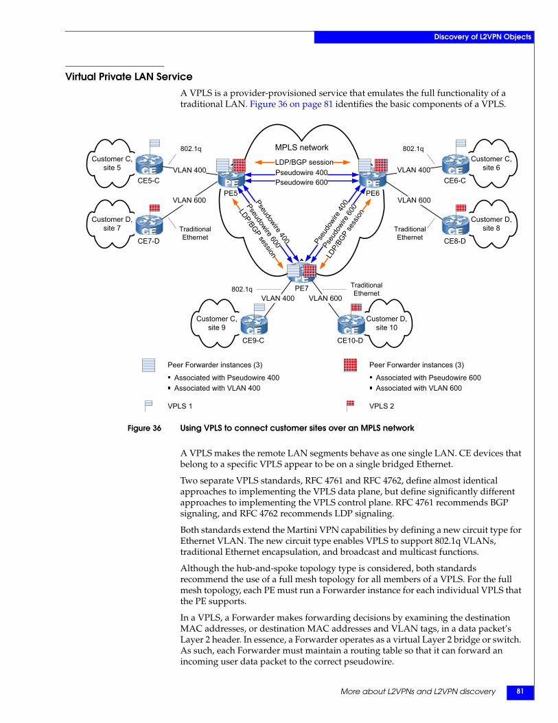
More about L2VPNs and L2VPN discovery 81
Discovery of L2VPN Objects
Virtual Private LAN ServiceA VPLS is a provider-provisioned service that emulates the full functionality of a traditional LAN. Figure 36 on page 81 identifies the basic components of a VPLS.
Figure 36 Using VPLS to connect customer sites over an MPLS network
A VPLS makes the remote LAN segments behave as one single LAN. CE devices that belong to a specific VPLS appear to be on a single bridged Ethernet.
Two separate VPLS standards, RFC 4761 and RFC 4762, define almost identical approaches to implementing the VPLS data plane, but define significantly different approaches to implementing the VPLS control plane. RFC 4761 recommends BGP signaling, and RFC 4762 recommends LDP signaling.
Both standards extend the Martini VPN capabilities by defining a new circuit type for Ethernet VLAN. The new circuit type enables VPLS to support 802.1q VLANs, traditional Ethernet encapsulation, and broadcast and multicast functions.
Although the hub-and-spoke topology type is considered, both standards recommend the use of a full mesh topology for all members of a VPLS. For the full mesh topology, each PE must run a Forwarder instance for each individual VPLS that the PE supports.
In a VPLS, a Forwarder makes forwarding decisions by examining the destination MAC addresses, or destination MAC addresses and VLAN tags, in a data packet’s Layer 2 header. In essence, a Forwarder operates as a virtual Layer 2 bridge or switch. As such, each Forwarder must maintain a routing table so that it can forward an incoming user data packet to the correct pseudowire.
MPLS network
Customer D, site 8
Customer C, site 6
CE6-C
CE8-D
Customer D, site 7
Customer C, site 5
CE5-C
CE7-D
LDP/BGP session
PE5 PE6
LDP/BGPsession LD
P/BG
Pse
ssion
Pseudowire 400Pseudowire 600
PE7
Customer D, site 10
CE10-D
Customer C, site 9
CE9-C
VLAN 600VLAN 400Pseudowire
400
Pseu
dowire
600
Pseu
dowire
400Pseudowire
600
VLAN 400
VLAN 600VLAN 600
VLAN 400
802.1q 802.1q
TraditionalEthernet
TraditionalEthernet
TraditionalEthernet802.1q
Peer Forwarder instances (3) Peer Forwarder instances (3)
VPLS 2VPLS 1
Associated with Pseudowire 400Associated with VLAN 400
Associated with Pseudowire 600Associated with VLAN 600
EMC Ionix MPLS Manager Version 3.1 Discovery Guide82
Discovery of L2VPN Objects
LDP-signaled VPLSThe pseudowire identifier VC ID in an LDP-signaled VPWS also has significance in an LDP-signaled VPLS.
In an LDP-signaled VPLS, each pseudowire may be configured with the same VC ID, or each pseudowire may be configured with a different VC ID. RFC 4762 allows both configurations, but recommends the former. For the former, the VC ID is considered the VPLS ID for the VPLS.
A VC ID is locally significant on a PE, but is not globally significant. In other words, two pseudowires with the same VC ID, say 100, one between PEa => PEb and the other between PEx => PEy, are independent of each other. No connection exists between the two pseudowires.
ForwarderEndpoints are peers only when both of them use the same VC ID and point to each other’s IP address. The combination of VC ID and peer IP address for a ForwarderEndpoint is globally unique.
BGP-signaled VPLSIn a BGP-signaled VPLS environment, each VPLS on each PE must be assigned a unique route target. The route target must be the same for a particular VPLS across all PEs that belong to the VPLS. The route target is the VPLS ID for a BGP-signaled VPLS.
Also, each PE must be assigned a unique site identifier. The site identifier is the same as the virtual edge identifier (VEID) that is defined in RFC 4761.
ForwarderEndpoints are peers only when they share complementary incoming VC ID and outgoing VC ID values. That is, the incoming VC ID for the one is the outgoing VC ID for the other, and the outgoing VC ID for the one is the incoming VC ID for the other.
L2VPN discoveryThe MPLS Topology Server is able to discover LDP-signaled VPWS and VPLS instances, and BGP-signaled VPWS and VPLS instances.
Because VPLS has many prototypes and is configured in many different ways from vendor to vendor, the MPLS Topology Server focuses on support of the more dominant types of VPLS. Specifically, the MPLS Topology Server focuses on the following:
◆ VPLS architectural type: flat architecture
The MPLS Topology Server discovers VPLS instances that employ the flat architecture type of VPLS, but does not discover VPLS instances that employ the hierarchical architecture (H-VPLS) type of VPLS. The latter type of VPLS is used to overcome control-plane scalability issues in an LDP-signaled VPLS.
◆ VPLS topology type: full mesh
MPLS Manager discovers VPLS instances that employ the full mesh topology, but does not discover VPLS instances that employ the hub-and-spoke topology.
◆ VPLS signaling protocol types: LDP, BGP
The MPLS Topology Server discovers VPLS instances that are exclusively signaled by either LDP or BGP, but does not discover VPLS instances that are signaled by both LDP and BGP.
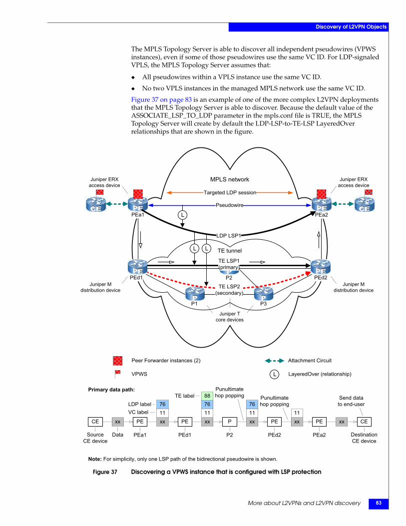
More about L2VPNs and L2VPN discovery 83
Discovery of L2VPN Objects
The MPLS Topology Server is able to discover all independent pseudowires (VPWS instances), even if some of those pseudowires use the same VC ID. For LDP-signaled VPLS, the MPLS Topology Server assumes that:
◆ All pseudowires within a VPLS instance use the same VC ID.
◆ No two VPLS instances in the managed MPLS network use the same VC ID.
Figure 37 on page 83 is an example of one of the more complex L2VPN deployments that the MPLS Topology Server is able to discover. Because the default value of the ASSOCIATE_LSP_TO_LDP parameter in the mpls.conf file is TRUE, the MPLS Topology Server will create by default the LDP-LSP-to-TE-LSP LayeredOver relationships that are shown in the figure.
Figure 37 Discovering a VPWS instance that is configured with LSP protection
MPLS network
TE tunnel
PEa1 PEa2
TE LSP1(primary)
TE LSP2(secondary)
P3P1
P2 PEd2PEd1
Juniper Tcore devices
Targeted LDP session
Juniper ERXaccess device
Juniper ERXaccess device
LDP LSP1
Juniper Mdistribution device
Juniper Mdistribution device
L
L L
Note: For simplicity, only one LSP path of the bidirectional pseudowire is shown.
CEPE PEPE P
PEa1 PEd2Data
Punultimatehop poppingLDP label
xx
VC label
DestinationCE device
xx11
76
xx11
76
xx11
CE
SourceCE device
PE xx
PEa2P2PEd1
xx
76Send datato end-user
88
11
Punultimatehop poppingTE label
Primary data path:
Peer Forwarder instances (2)
VPWS
Attachment Circuit
LayeredOver (relationship)L
Pseudowire
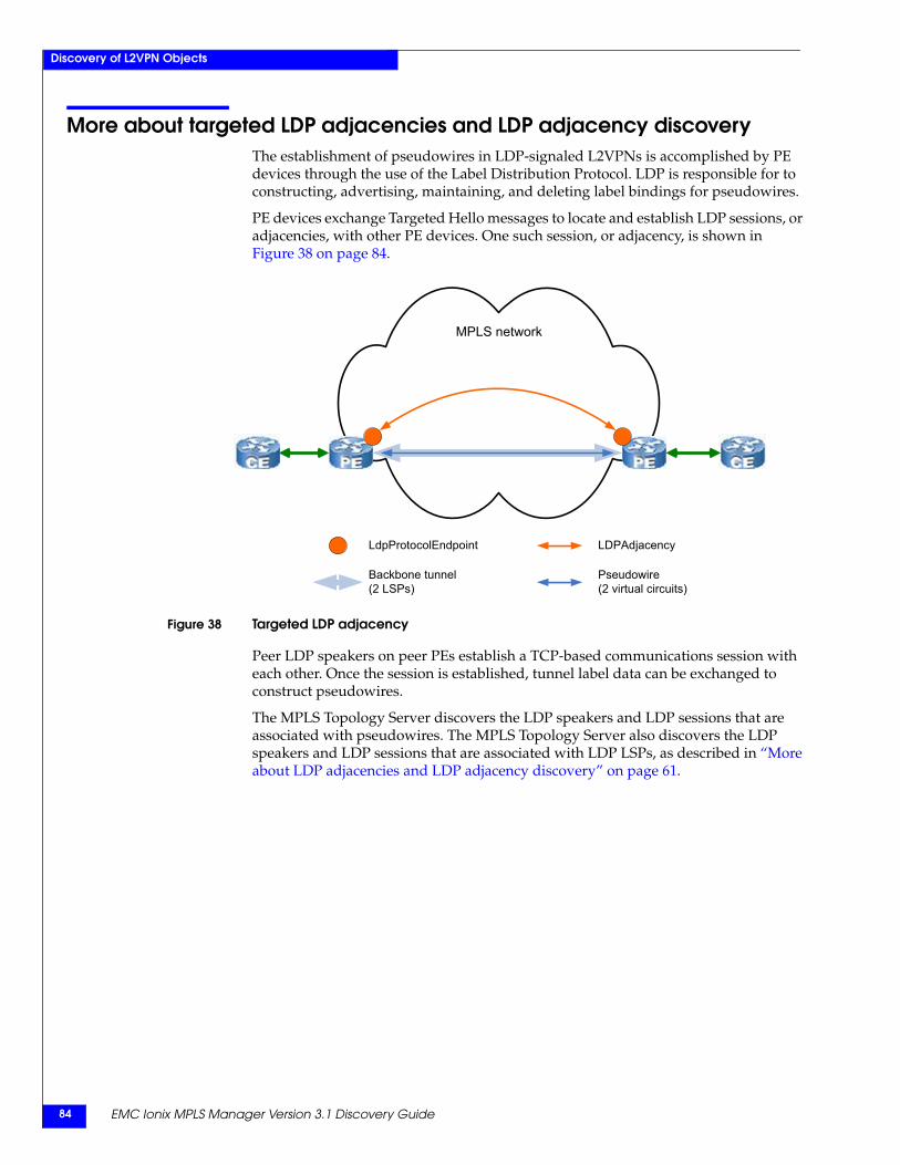
EMC Ionix MPLS Manager Version 3.1 Discovery Guide84
Discovery of L2VPN Objects
More about targeted LDP adjacencies and LDP adjacency discoveryThe establishment of pseudowires in LDP-signaled L2VPNs is accomplished by PE devices through the use of the Label Distribution Protocol. LDP is responsible for to constructing, advertising, maintaining, and deleting label bindings for pseudowires.
PE devices exchange Targeted Hello messages to locate and establish LDP sessions, or adjacencies, with other PE devices. One such session, or adjacency, is shown in Figure 38 on page 84.
Figure 38 Targeted LDP adjacency
Peer LDP speakers on peer PEs establish a TCP-based communications session with each other. Once the session is established, tunnel label data can be exchanged to construct pseudowires.
The MPLS Topology Server discovers the LDP speakers and LDP sessions that are associated with pseudowires. The MPLS Topology Server also discovers the LDP speakers and LDP sessions that are associated with LDP LSPs, as described in “More about LDP adjacencies and LDP adjacency discovery” on page 61.
MPLS network
LdpProtocolEndpoint LDPAdjacency
Backbone tunnel (2 LSPs)
Pseudowire (2 virtual circuits)
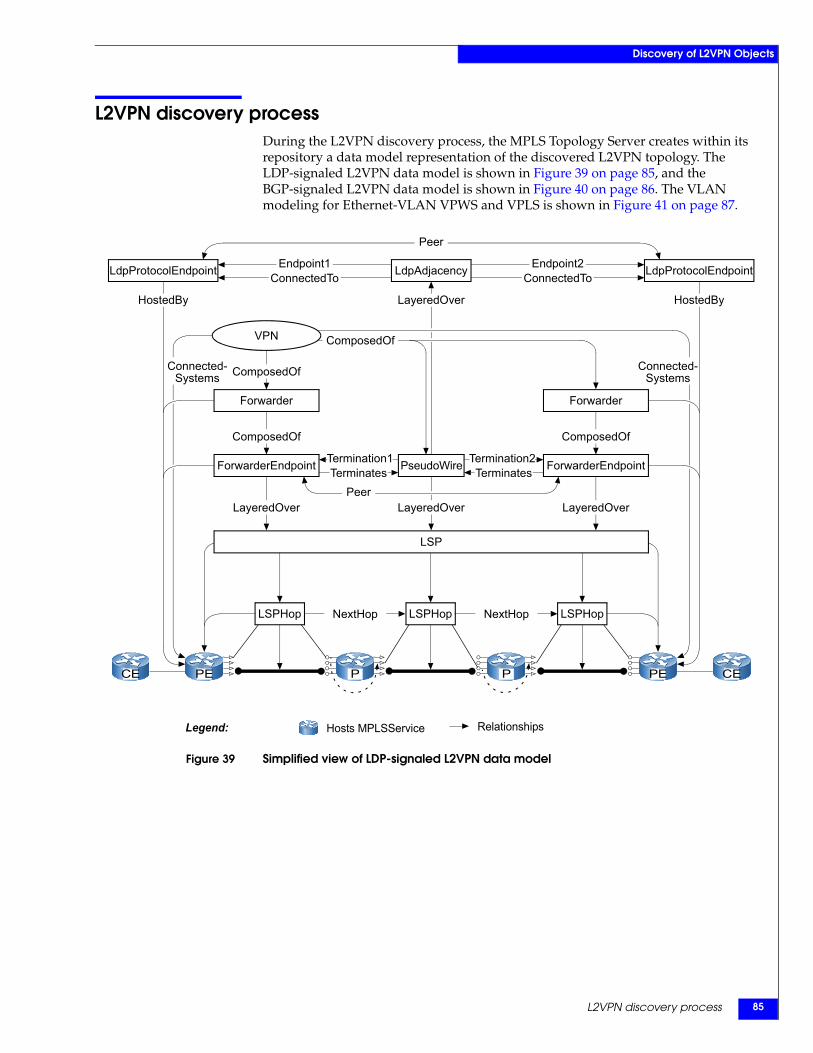
L2VPN discovery process 85
Discovery of L2VPN Objects
L2VPN discovery processDuring the L2VPN discovery process, the MPLS Topology Server creates within its repository a data model representation of the discovered L2VPN topology. The LDP-signaled L2VPN data model is shown in Figure 39 on page 85, and the BGP-signaled L2VPN data model is shown in Figure 40 on page 86. The VLAN modeling for Ethernet-VLAN VPWS and VPLS is shown in Figure 41 on page 87.
Figure 39 Simplified view of LDP-signaled L2VPN data model
LayeredOver LayeredOver
RelationshipsHosts MPLSServiceLegend:
Termination1Terminates
ComposedOf
Termination2Terminates
LayeredOver
PseudoWire
Endpoint1ConnectedTo LdpAdjacency Endpoint2
ConnectedTo
LayeredOver
Peer
Peer
ComposedOf ComposedOf
P P PEPE
LSPHopLSPHopLSPHop
LSP
CECE
ComposedOf
ForwarderEndpoint
Forwarder
Connected-Systems
VPN
Forwarder
ForwarderEndpoint
HostedBy
LdpProtocolEndpoint
Connected-Systems
LdpProtocolEndpoint
HostedBy
NextHop NextHop
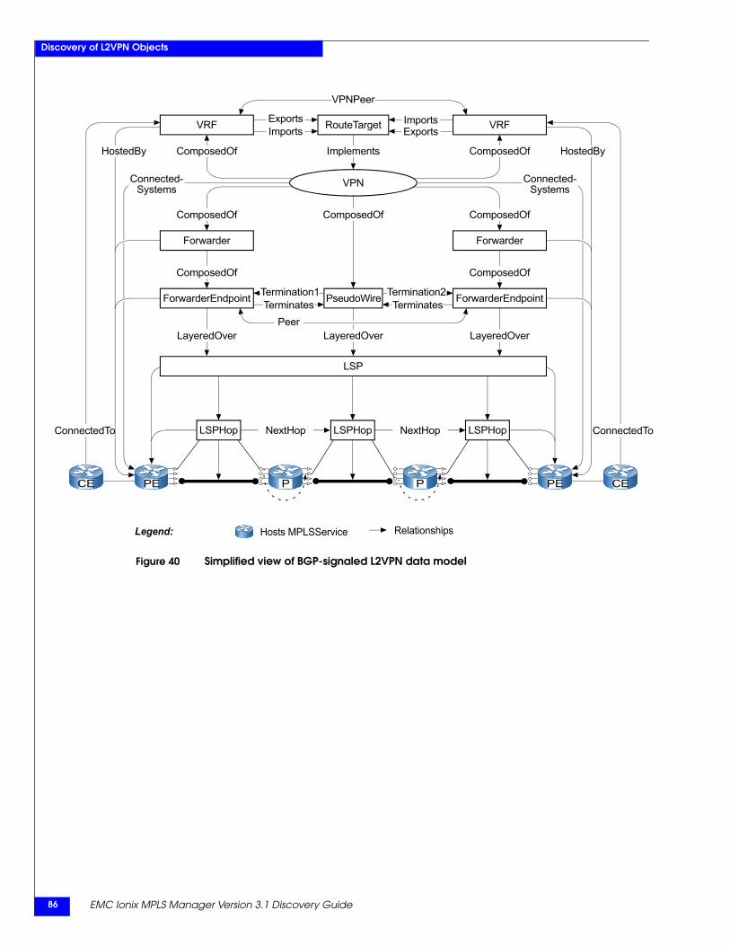
EMC Ionix MPLS Manager Version 3.1 Discovery Guide86
Discovery of L2VPN Objects
Figure 40 Simplified view of BGP-signaled L2VPN data model
P PCE PE CEPE
LayeredOver LayeredOver
Hosts MPLSServiceLegend:
Termination1Terminates
ComposedOf
LSP
Termination2Terminates
LayeredOver
PseudoWire
Peer
ComposedOf ComposedOf
LSPHopLSPHopLSPHop
Connected-Systems
Connected-Systems
ConnectedTo ConnectedTo
VPN
ComposedOf
ImplementsComposedOf ComposedOf
ComposedOf
HostedBy
Relationships
ExportsExports RouteTargetVRF VRF
HostedBy
Forwarder
ForwarderEndpoint ForwarderEndpoint
Forwarder
NextHop NextHop
ImportsImports
VPNPeer
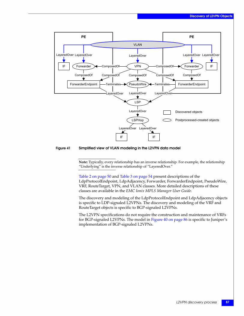
L2VPN discovery process 87
Discovery of L2VPN Objects
Figure 41 Simplified view of VLAN modeling in the L2VPN data model
Note: Typically, every relationship has an inverse relationship. For example, the relationship “Underlying” is the inverse relationship of “LayeredOver.”
Table 2 on page 50 and Table 3 on page 54 present descriptions of the LdpProtocolEndpoint, LdpAdjacency, Forwarder, ForwarderEndpoint, PseudoWire, VRF, RouteTarget, VPN, and VLAN classes. More detailed descriptions of these classes are available in the EMC Ionix MPLS Manager User Guide.
The discovery and modeling of the LdpProtocolEndpoint and LdpAdjacency objects is specific to LDP-signaled L2VPNs. The discovery and modeling of the VRF and RouteTarget objects is specific to BGP-signaled L2VPNs.
The L2VPN specifications do not require the construction and maintenance of VRFs for BGP-signaled L2VPNs. The model in Figure 40 on page 86 is specific to Juniper’s implementation of BGP-signaled L2VPNs.
PEPE
PseudoWireTerminatesForwarderEndpoint
LayeredOver
LSP
LSPHop
IFIF VPNForwarder Forwarder
ForwarderEndpoint
VLAN
LayeredOver
Terminates
LayeredOver
LayeredOver
LayeredOverLayeredOver
IFIF
ComposedOfComposedOf ComposedOf
LayeredOverLayeredOver LayeredOver
ComposedOfComposedOf
ComposedOf ComposedOf
LayeredOverLayeredOver
Postprocessed-created objects
Discovered objects
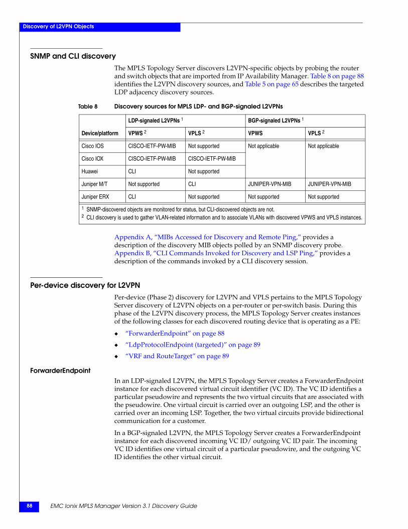
EMC Ionix MPLS Manager Version 3.1 Discovery Guide88
Discovery of L2VPN Objects
SNMP and CLI discoveryThe MPLS Topology Server discovers L2VPN-specific objects by probing the router and switch objects that are imported from IP Availability Manager. Table 8 on page 88 identifies the L2VPN discovery sources, and Table 5 on page 65 describes the targeted LDP adjacency discovery sources.
Appendix A, “MIBs Accessed for Discovery and Remote Ping,” provides a description of the discovery MIB objects polled by an SNMP discovery probe. Appendix B, “CLI Commands Invoked for Discovery and LSP Ping,” provides a description of the commands invoked by a CLI discovery session.
Per-device discovery for L2VPNPer-device (Phase 2) discovery for L2VPN and VPLS pertains to the MPLS Topology Server discovery of L2VPN objects on a per-router or per-switch basis. During this phase of the L2VPN discovery process, the MPLS Topology Server creates instances of the following classes for each discovered routing device that is operating as a PE:
◆ “ForwarderEndpoint” on page 88
◆ “LdpProtocolEndpoint (targeted)” on page 89
◆ “VRF and RouteTarget” on page 89
ForwarderEndpointIn an LDP-signaled L2VPN, the MPLS Topology Server creates a ForwarderEndpoint instance for each discovered virtual circuit identifier (VC ID). The VC ID identifies a particular pseudowire and represents the two virtual circuits that are associated with the pseudowire. One virtual circuit is carried over an outgoing LSP, and the other is carried over an incoming LSP. Together, the two virtual circuits provide bidirectional communication for a customer.
In a BGP-signaled L2VPN, the MPLS Topology Server creates a ForwarderEndpoint instance for each discovered incoming VC ID/ outgoing VC ID pair. The incoming VC ID identifies one virtual circuit of a particular pseudowire, and the outgoing VC ID identifies the other virtual circuit.
Table 8 Discovery sources for MPLS LDP- and BGP-signaled L2VPNs
Device/platform
LDP-signaled L2VPNs 1 BGP-signaled L2VPNs 1
VPWS 2 VPLS 2 VPWS VPLS 2
Cisco IOS CISCO-IETF-PW-MIB Not supported Not applicable Not applicable
Cisco IOX CISCO-IETF-PW-MIB CISCO-IETF-PW-MIB
Huawei CLI Not supported
Juniper M/T Not supported CLI JUNIPER-VPN-MIB JUNIPER-VPN-MIB
Juniper ERX CLI Not supported Not supported Not supported
1 SNMP-discovered objects are monitored for status, but CLI-discovered objects are not.2 CLI discovery is used to gather VLAN-related information and to associate VLANs with discovered VPWS and VPLS instances.
L2VPN discovery process 89
Discovery of L2VPN Objects
LdpProtocolEndpoint (targeted)In an environment that is using LDP signaling to establish L2VPNs, the MPLS Topology Server discovers the PE devices and the LDP speakers that are associated with the L2VPNs. It creates an LdpProtocolEndpoint instance for each discovered LDP speaker, and sets the IsTargetedPeer attribute of each instance to True, to indicates that each instance’s termination point is to a targeted peer.
LDP-signaled L2VPNs use LDP signaling to construct, advertise, maintain, and delete pseudowires.
Here are some relationships that are created for LdpProtocolEndpoint (targeted):
◆ LdpProtocolEndpoint relationship HostedBy
Relates an LdpProtocolEndpoint to the PE device that hosts the LDP speaker that is represented by the LdpProtocolEndpoint.
◆ LdpProtocolEndpoint relationship LayeredOver
Points from an LdpProtocolEndpoint to the interface and IP address, on the host PE device, that are associated with the LdpProtocolEndpoint.
◆ LdpProtocolEndpoint relationship Peer
Points from an LdpProtocolEndpoint to the endpoint at the other end of the LdpAdjacency. Because an LDP session is TCP-based, a peer LdpProtocolEndpoint can terminate on a PE device that is multiple Layer 3 hops away.
VRF and RouteTargetFor a BGP-signaled L2VPN in a Juniper environment, the MPLS Topology Server creates a VRF instance and a RouteTarget instance for each discovered VRF and route target that are associated with the L2VPN. BGP-signaled L2VPNs not only use BGP signaling to construct, advertise, maintain, and delete pseudowires, but also use BGP and route targets to discover all the VRFs that belong to an L2VPN.
In a BGP-signaled VPLS, the route target is the same for the VPLS across all VRFs/PEs that belong to the VPLS. The route target is the VPLS ID for a BGP-signaled VPLS.
As with the discovery and modeling of L3VPNs, the MPLS Topology Server relates VRFs and RouteTargets through the Imports/ImportedBy and Exports/ExportedBy relationship sets, and then discovers which interfaces are associated with each VRF. By matching the VRF interfaces to the ForwarderEndpoint interfaces, the MPLS Topology Server discovers which Forwarders, ForwarderEndpoints, and PseudoWires are part of a VPN.
“VRF and RouteTarget” on page 102 describes additional relationships that are created for VRFs and RouteTargets.
EMC Ionix MPLS Manager Version 3.1 Discovery Guide90
Discovery of L2VPN Objects
Post-processing discovery for L2VPNDuring this phase (Phase 3) of the L2VPN discovery process, which starts after per-device discovery completes, the MPLS Topology Server creates instances of the following classes by combining the information that is collected during per-device L2VPN and MPLS discovery:
◆ “PseudoWire” on page 90
◆ “Forwarder” on page 92
◆ “LdpAdjacency (targeted)” on page 92
◆ “VPN” on page 93
◆ “VLAN” on page 93
Also, during this phase, the MPLS Topology Server creates the relationships that associate the L2VPN with the underlying LSPs.
PseudoWireIn an LDP-signaled L2VPN, the MPLS Topology Server checks the VC IDs and peer ForwarderEndpoint IP addresses that are associated with the discovered ForwarderEndpoints, and creates a PseudoWire instance for each complementary match. For example, due to the following complementary match, the MPLS Topology Server will create a PseudoWire instance between ForwarderEndpoint1 and ForwarderEndpoint2:
◆ ForwarderEndpoint1: VC ID = 122, peer IP = 192.168.5.1, local IP = 192.168.19.1
◆ ForwarderEndpoint2: VC ID = 122, peer IP = 192.168.19.1, local IP = 192.168.5.1
In a BGP-signaled L2VPN, the MPLS Topology Server checks the incoming VC ID/ outgoing VC ID pairs that are associated with the discovered ForwarderEndpoints, and creates a PseudoWire instance for each complementary match. For example, due to the following complementary match, the MPLS Topology Server will create a PseudoWire instance between ForwarderEndpointA and ForwarderEndpointB:
◆ ForwarderEndpointA: incoming VC ID/ outgoing VC ID = 262401/262406
◆ ForwarderEndpointB: incoming VC ID/ outgoing VC ID = 262406/262401
A PseudoWire is TerminatedBy two ForwarderEndpoints, where one ForwarderEndpoint is HostedBy one PE device, and the second ForwarderEndpoint is HostedBy another PE device. The PseudoWire is associated with a pair of LSPs, and provides a bidirectional data path between the two PE devices. The LSPs can be TE LSPs or LDP LSPs.
Because the MPLS Topology Server can discover LSPs that traverse a mixture of multi-vendor devices as long as the LSPs originate and terminate on same-vendor devices, the same can be said of PseudoWires. For example, the MPLS Topology Server can discover a PseudoWire that traverses any mixture of Cisco and Juniper M/T devices, as long as the PseudoWire originates and terminates on same-vendor PE devices, say a pair of Cisco PEs.
L2VPN discovery process 91
Discovery of L2VPN Objects
The MPLS Topology Server relates a ForwarderEndpoint with a PseudoWire and other discovered objects through the following computed relationships:
◆ ForwarderEndpoint relationship Terminates
Relates a ForwarderEndpoint to the PseudoWire that is terminated by the ForwarderEndpoint.
◆ ForwarderEndpoint relationship LayeredOver
Points from a ForwarderEndpoint to the pair of LSPs that are underlying the PseudoWire.
Also points to the interface, on the host PE device, that is associated with the ForwarderEndpoint.
◆ ForwarderEndpoint relationship Underlying
For a ForwarderEndpoint that is associated with an Ethernet VLAN, points from the ForwarderEndpoint to the VLAN.
◆ ForwarderEndpoint relationship Peer
Points from a ForwarderEndpoint to the ForwarderEndpoint that terminates the other end of the PseudoWire.
◆ ForwarderEndpoint relationship PartOf
Points to the Forwarder to which this ForwarderEndpoint belongs.
Points to the VPN to which this ForwarderEndpoint belongs.
◆ ForwarderEndpoint relationship HostedBy
Relates a ForwarderEndpoint to the PE device that is hosting the ForwarderEndpoint.
◆ BGP-signaled L2VPN only: ForwarderEndpoint relationship RT
Relates a ForwarderEndpoint to the RouteTarget of the L2VPN to which the ForwarderEndpoint belongs.
Some computed relationships for PseudoWires are:
◆ PseudoWire relationship LayeredOver
Points from a PseudoWire to the pair of LSPs that are underlying the PseudoWire.
Points to the interface, on the host PE device, that is associated with the PseudoWire.
LDP-signaled L2VPN only: Points from a PseudoWire to the LdpAdjacency that is providing the signaling for the L2VPN to which the PseudoWire belongs.
◆ PseudoWire relationship VLANs
For a PseudoWire that is associated with an Ethernet VLAN, points from the PseudoWire to the VLAN.
EMC Ionix MPLS Manager Version 3.1 Discovery Guide92
Discovery of L2VPN Objects
ForwarderA Forwarder is hosted by a PE device and contains the procedures to make the switching and forwarding decisions for an L2VPN.
In VPWS, a Forwarder binds exactly one MPLS-side PseudoWire to exactly one customer-side Attachment Circuit—a VLAN or an Ethernet port, for example—that is attached to a CE. A VPWS Forwarder has exactly one ForwarderEndpoint.
In VPLS, a Forwarder binds a set of PseudoWires to an Attachment Circuit. A VPLS Forwarder has multiple ForwarderEndpoints.
For a VPWS discovered on a PE device, the MPLS Topology Server creates a Forwarder instance for the ForwarderEndpoint that it discovered and created for the VPWS on the PE device. For a VPLS discovered on a PE device, the MPLS Topology Server creates a Forwarder instance for the set of ForwarderEndpoints that it discovered and created for the VPLS on the PE device.
The MPLS Topology Server relates a Forwarder with its one or more ForwarderEndpoints and other discovered objects through the following computed relationships:
◆ Forwarder relationship ComposedOf
Relates the Forwarder to its one or more ForwarderEndpoints.
◆ Forwarder relationship LayeredOver
Points from a Forwarder to all LSPs that are underlying the one or more PseudoWires that are terminated by the one or more ForwarderEndpoints that are part of the Forwarder.
◆ Forwarder relationship Underlying
Points from a Forwarder to the one or more PseudoWires that are terminated by the one or more ForwarderEndpoints that are part of the Forwarder.
For a Forwarder that is associated with an Ethernet VLAN, points from the Forwarder to the VLAN.
◆ Forwarder relationship HostedBy
Relates a Forwarder to the PE device that is hosting the Forwarder.
LdpAdjacency (targeted)In an environment that is using LDP signaling to establish L2VPNs, the MPLS Topology Server matches various attributes (LocalAddress, PeerAddress) that are associated with the LdpProtocolEndpoints that are discovered on different PE devices, and creates an LdpAdjacency instance for each complementary match. The MPLS Topology Server sets each instance’s isTargeted attribute to True, to indicates that the LDP session is targeted.
An LdpAdjacency is ConnectedTo two LdpProtocolEndpoints, where one LdpProtocolEndpoint is HostedBy one PE device, and the second is HostedBy another PE device. The LdpAdjacency provides a bidirectional signaling path through which the two PE devices exchange VC ID and other types of information for the purpose of constructing, advertising, maintaining, or deleting PseudoWires between the two PE devices.
L2VPN discovery process 93
Discovery of L2VPN Objects
Here are some other relationships that are computed for LdpAdjacency (targeted):
◆ LdpAdjacency relationship Endpoint1
Points from an LdpAdjacency to the LdpProtocolEndpoint that has the lower IP address of the two endpoints that are associated with the LdpAdjacency.
◆ LdpAdjacency relationship Endpoint2
Points from an LdpAdjacency to the LdpProtocolEndpoint that has the higher IP address of the two endpoints that are associated with the LdpAdjacency.
◆ LdpAdjacency relationship Underlying
Points from an LdpAdjacency to the one or more PseudoWires that are associated with the LdpAdjacency.
VPNFor discovered LDP-signaled L2VPNs, the MPLS Topology Server infers VPNs from Forwarder, ForwarderEndpoint, and PseudoWire instances and the relationships between the instances. An LDP-signaled L2VPN is composed of Forwarders, ForwarderEndpoints, and PseudoWires.
In an LDP-signaled VPLS, the VC ID is the same for each pseudowire that belongs to the VPLS. The VC ID is the VPLS ID for an LDP-signaled VPLS.
For discovered BGP-signaled L2VPNs, the MPLS Topology Server infers VPNs from Forwarder, ForwarderEndpoint, PseudoWire, VRF, and RouteTarget instances and the relationships between the instances. The MPLS Topology Server matches the underlying interfaces of the VRFs with the underlying interfaces of the ForwarderEndpoints to determine which Forwarders, ForwarderEndpoints, and PseudoWires belong to a VPN. A BGP-signaled Layer 2 VPN is composed of Forwarders, ForwarderEndpoints, PseudoWires, VRFs, and RouteTargets.
In a BGP-signaled VPLS, the route target is the same for the VPLS across all PEs that belong to the VPLS. The route target is the VPLS ID for a BGP-signaled VPLS.
For a VPN that is associated with an Ethernet VLAN, the VPN relationship Underlying points to the VLAN.
VLANThe discovery of VLANs is a new feature in MPLS Management Suite 3.1. In previous releases, the MPLS Topology Server imported VLAN objects from IP Availability Manager. Because the VLAN objects that are discovered and created by IP Availability Manager are physically oriented, not traffic-content oriented as required by the MPLS Topology Server, the MPLS Topology Server in MPLS Management Suite 3.1 discovers and creates VLAN objects.
The MPLS Topology Server creates a VLAN instance for each discovered Ethernet-VLAN VPWS that is implemented on Cisco devices, and for each discovered VPLS. For each discovered Cisco-based Ethernet-VLAN VPWS, the MPLS Topology Server uses the discovered VLAN ID to map the associated customer VLAN to the VPWS. For each discovered VPLS, the MPLS Topology Server uses the discovered VLAN ID and VLAN MPLS-side interfaces to map the associated customer VLAN to the VPLS.
A VLAN is layered over a single VPWS or VPLS, two or more Forwarders, and two or more interfaces.
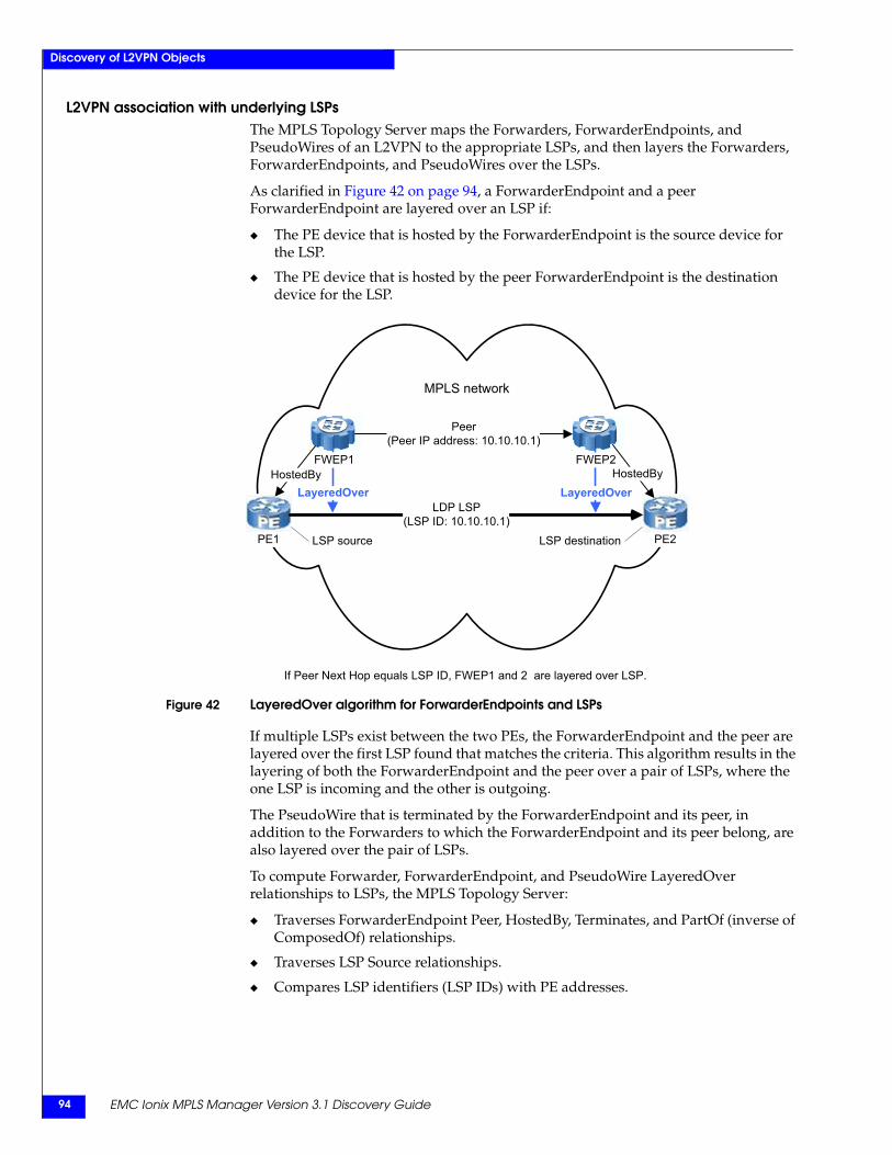
EMC Ionix MPLS Manager Version 3.1 Discovery Guide94
Discovery of L2VPN Objects
L2VPN association with underlying LSPsThe MPLS Topology Server maps the Forwarders, ForwarderEndpoints, and PseudoWires of an L2VPN to the appropriate LSPs, and then layers the Forwarders, ForwarderEndpoints, and PseudoWires over the LSPs.
As clarified in Figure 42 on page 94, a ForwarderEndpoint and a peer ForwarderEndpoint are layered over an LSP if:
◆ The PE device that is hosted by the ForwarderEndpoint is the source device for the LSP.
◆ The PE device that is hosted by the peer ForwarderEndpoint is the destination device for the LSP.
Figure 42 LayeredOver algorithm for ForwarderEndpoints and LSPs
If multiple LSPs exist between the two PEs, the ForwarderEndpoint and the peer are layered over the first LSP found that matches the criteria. This algorithm results in the layering of both the ForwarderEndpoint and the peer over a pair of LSPs, where the one LSP is incoming and the other is outgoing.
The PseudoWire that is terminated by the ForwarderEndpoint and its peer, in addition to the Forwarders to which the ForwarderEndpoint and its peer belong, are also layered over the pair of LSPs.
To compute Forwarder, ForwarderEndpoint, and PseudoWire LayeredOver relationships to LSPs, the MPLS Topology Server:
◆ Traverses ForwarderEndpoint Peer, HostedBy, Terminates, and PartOf (inverse of ComposedOf) relationships.
◆ Traverses LSP Source relationships.
◆ Compares LSP identifiers (LSP IDs) with PE addresses.
LayeredOver LayeredOver
VRF1FWEP1
MPLS network
PE1
HostedBy
PE2
HostedBy
Peer(Peer IP address: 10.10.10.1)
LDP LSP(LSP ID: 10.10.10.1)
LSP destinationLSP source
FWEP2
If Peer Next Hop equals LSP ID, FWEP1 and 2 are layered over LSP.
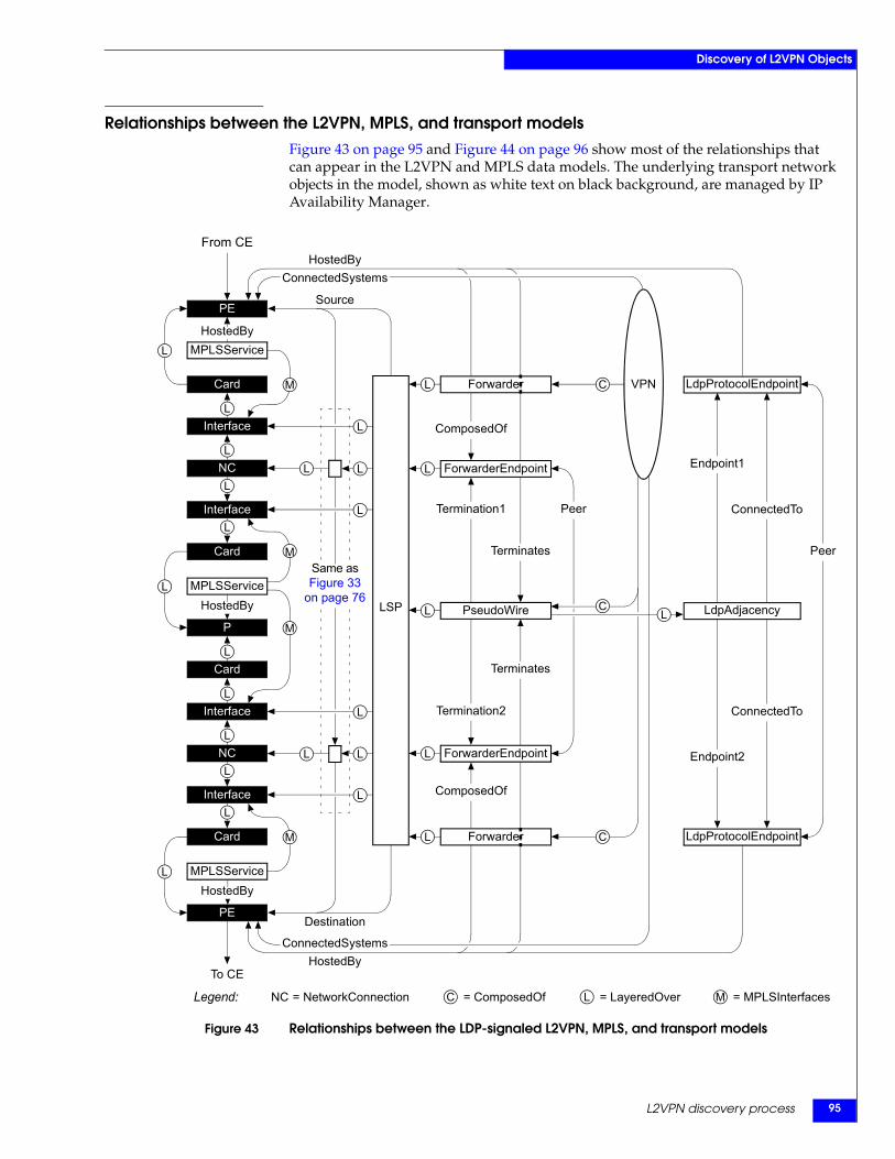
L2VPN discovery process 95
Discovery of L2VPN Objects
Relationships between the L2VPN, MPLS, and transport modelsFigure 43 on page 95 and Figure 44 on page 96 show most of the relationships that can appear in the L2VPN and MPLS data models. The underlying transport network objects in the model, shown as white text on black background, are managed by IP Availability Manager.
Figure 43 Relationships between the LDP-signaled L2VPN, MPLS, and transport models
L
L
HostedByMPLSService
PE
Interface
Card
From CE
To CE
L
L
Interface
Card
NC
L
L
HostedByMPLSService
P
Interface
Card
L
L
HostedBy
PE
Interface
Card
NC
L
L
L
L
L
L
M
L
M
L
L
L
MPLSService
LSP
Source
Termination1
Terminates
L
Termination2
Terminates
HostedBy
Peer
L
Endpoint1
ConnectedTo
Endpoint2
ConnectedTo
PseudoWire
C
C
L
L
L
L
L
Destination
Same as Figure 33
on page 76
ForwarderEndpoint
ComposedOf
ComposedOf
Peer
C
HostedBy
Forwarder
ForwarderEndpoint
LdpProtocolEndpoint
LdpAdjacency
LdpProtocolEndpointForwarder
VPN
Legend: = NetworkConnection C = ComposedOf L = LayeredOverNC M = MPLSInterfaces
ConnectedSystems
ConnectedSystems
M
M
L
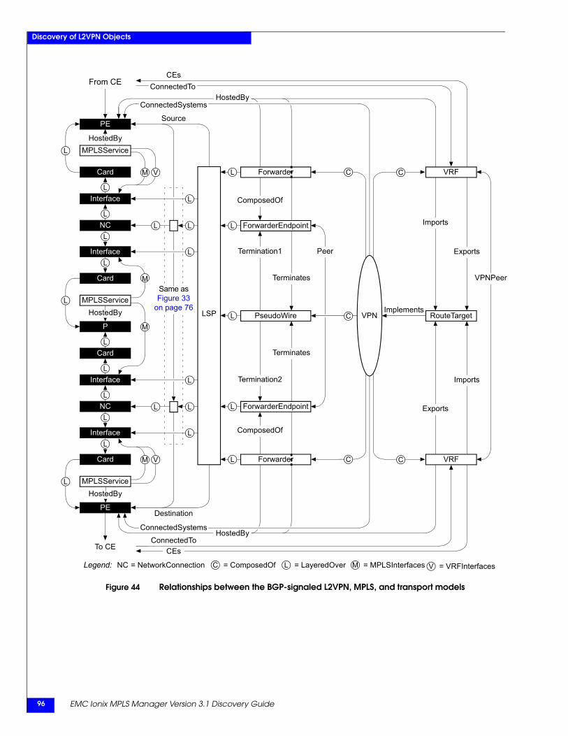
EMC Ionix MPLS Manager Version 3.1 Discovery Guide96
Discovery of L2VPN Objects
Figure 44 Relationships between the BGP-signaled L2VPN, MPLS, and transport models
HostedByMPLSService
PE
Interface
Card
From CE
To CE
L
L
Interface
Card
NC
L
L
HostedByMPLSService
P
Interface
Card
L
L
HostedBy
PE
Interface
Card
NC
L
L
L
L
L
L
M
M
MPLSService
LSP
Source
VPNPeer
Imports
Exports
Exports
Implements
ConnectedToCEs
CEsConnectedTo
HostedBy
RouteTarget
C
C
C
C
HostedBy
VRF
C VPN
VRF
V = VRFInterfacesLegend: = NetworkConnection C = ComposedOf L = LayeredOverNC M = MPLSInterfaces
L
L L
L
L
L
L
L
Destination
L
L
L
Termination1
Terminates
L
Termination2
Terminates
L PseudoWire
ForwarderEndpoint
ComposedOf
ComposedOf
ForwarderEndpoint
Forwarder
ConnectedSystems
Forwarder
ConnectedSystems
Peer
Same as Figure 33
on page 76
Imports
M V
M V
Discovery of L3VPN Objects 97
6
This chapter describes the L3VPN discovery performed by MPLS Manager. It consists of the following sections:
◆ L3VPN discovery overview.......................................................................................... 98◆ More about L3VPNs and L3VPN discovery .............................................................. 98◆ L3VPN discovery process ........................................................................................... 101
Discovery of L3VPNObjects
EMC Ionix MPLS Manager Version 3.1 Discovery Guide98
Discovery of L3VPN Objects
L3VPN discovery overviewFor L3VPN discovery, the MPLS Topology Server component of MPLS Manager is able to discover and model MPLS Layer 3 VPN entities. It relates the discovered L3VPNs to the MPLS and transport domains by creating logical and physical relationships between the L3VPN entities and the underlying MPLS entities and Layer 3 devices.
Although L3VPN discovery is enabled by default, the MPLS Topology Server requires a Level 3 VPN feature license for the discovery of L3VPNs. The EMC Smarts System Administration Guide provides information about licensing.
More about L3VPNs and L3VPN discoveryL3VPNs, defined in RFC 2547bis, are provider-provisioned Layer 3 VPNs that extend the customer’s Layer 3 connectivity through an MPLS network. They use extensions to the existing Internet routing protocol BGPv4 to interconnect customer sites.
Like L2VPNs, L3VPNs depend entirely on the PE devices. Unlike L2VPNs, L3VPNs require that the PE devices participate in the customer’s routing algorithms. The PE devices run the routing protocols of the customer’s choice, and they support the IP address scheme that is implemented by the customer.
The L3VPN control plane uses Multiprotocol Border Gateway Protocol, which is referred to as “BGP” in the discussions that follow. The PE devices in an L3VPN use BGP signaling to exchange reachability information with one another.
The L3VPN data plane is based on the VPN tunnel, which consists of two LSPs between a pair of PE devices that are participating in an L3VPN. One LSP is outgoing, and the other is an incoming. Together, the two LSPs provide bidirectional communication for a customer.
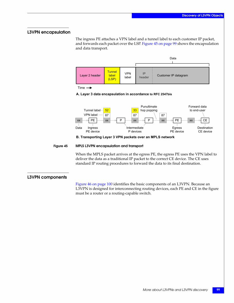
More about L3VPNs and L3VPN discovery 99
Discovery of L3VPN Objects
L3VPN encapsulationThe ingress PE attaches a VPN label and a tunnel label to each customer IP packet, and forwards each packet over the LSP. Figure 45 on page 99 shows the encapsulation and data transport.
Figure 45 MPLS L3VPN encapsulation and transport
When the MPLS packet arrives at the egress PE, the egress PE uses the VPN label to deliver the data as a traditional IP packet to the correct CE device. The CE uses standard IP routing procedures to forward the data to its final destination.
L3VPN componentsFigure 46 on page 100 identifies the basic components of an L3VPN. Because an L3VPN is designed for interconnecting routing devices, each PE and CE in the figure must be a router or a routing-capable switch.
Tunnellabel(LSP)
VPNlabelLayer 2 header
Data
Time
Customer IP datagramIPheader
CExx PE PEP P
IngressPE device
EgressPE device
Data
Punultimatehop poppingTunnel label
xx
IntermediateP devices
VPN label
DestinationCE device
Forward datato end-user
xx87
33
xx87
52
xx87
A. Layer 3 data encapsulation in accordance to RFC 2547bis
B. Transporting Layer 3 VPN packets over an MPLS network
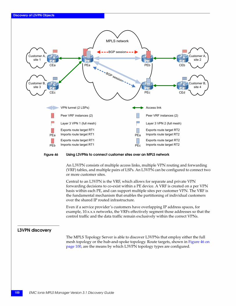
EMC Ionix MPLS Manager Version 3.1 Discovery Guide100
Discovery of L3VPN Objects
Figure 46 Using L3VPNs to connect customer sites over an MPLS network
An L3VPN consists of multiple access links, multiple VPN routing and forwarding (VRF) tables, and multiple pairs of LSPs. An L3VPN can be configured to connect two or more customer sites.
Central to an L3VPN is the VRF, which allows for separate and private VPN forwarding decisions to co-exist within a PE device. A VRF is created on a per VPN basis within each PE, and can support multiple sites per customer VPN. The VRF is the fundamental mechanism that enables the partitioning of individual customers over the shared IP routed infrastructure.
Even if a service provider’s customers have overlapping IP address spaces, for example, 10.x.x.x networks, the VRFs effectively segment those addresses so that the control traffic and the data traffic remain exclusively within the correct VPNs.
L3VPN discoveryThe MPLS Topology Server is able to discover L3VPNs that employ either the full mesh topology or the hub-and-spoke topology. Route targets, shown in Figure 46 on page 100, are the means by which L3VPN topology types are configured.
BGP session
MPLS network
Customer B,site 4
CEd
Customer B, site 3
CEc PEc
Customer A,site 2
CEb
Customer A, site 1
CEa PEa PEb
BGP session
VPN tunnel (2 LSPs)
PEa
PEb
PEa
RcPEc
Peer VRF instances (2)
Layer 3 VPN 2 (full mesh)
Exports route target RT2Imports route target RT2
Exports route target RT2Imports route target RT2
Peer VRF instances (2)
Layer 3 VPN 1 (full mesh)
Exports route target RT1Imports route target RT1
Exports route target RT1Imports route target RT1
Access link
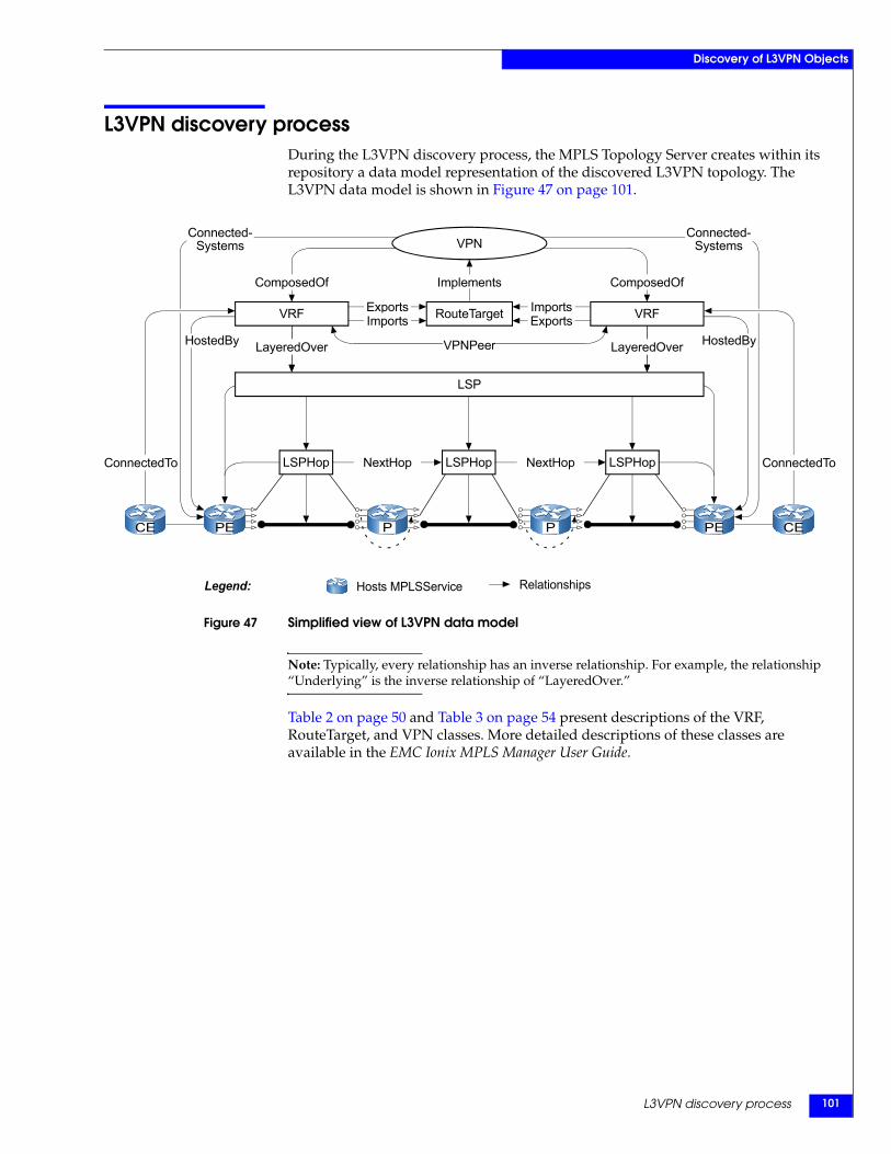
L3VPN discovery process 101
Discovery of L3VPN Objects
L3VPN discovery processDuring the L3VPN discovery process, the MPLS Topology Server creates within its repository a data model representation of the discovered L3VPN topology. The L3VPN data model is shown in Figure 47 on page 101.
Figure 47 Simplified view of L3VPN data model
Note: Typically, every relationship has an inverse relationship. For example, the relationship “Underlying” is the inverse relationship of “LayeredOver.”
Table 2 on page 50 and Table 3 on page 54 present descriptions of the VRF, RouteTarget, and VPN classes. More detailed descriptions of these classes are available in the EMC Ionix MPLS Manager User Guide.
P PCE PE CEPE
Hosts MPLSServiceLegend:
ComposedOf
LSP
LSPHopLSPHopLSPHop
Connected-Systems
Connected-Systems
ConnectedTo ConnectedTo
VPN
ComposedOf
Relationships
HostedByHostedBy LayeredOver LayeredOver
VRF VRF
Implements
RouteTarget
NextHop NextHop
ExportsExports ImportsImports
VPNPeer
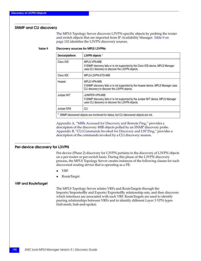
EMC Ionix MPLS Manager Version 3.1 Discovery Guide102
Discovery of L3VPN Objects
SNMP and CLI discoveryThe MPLS Topology Server discovers L3VPN-specific objects by probing the router and switch objects that are imported from IP Availability Manager. Table 9 on page 102 identifies the L3VPN discovery sources.
Appendix A, “MIBs Accessed for Discovery and Remote Ping,” provides a description of the discovery MIB objects polled by an SNMP discovery probe. Appendix B, “CLI Commands Invoked for Discovery and LSP Ping,” provides a description of the commands invoked by a CLI discovery session.
Per-device discovery for L3VPNPer-device (Phase 2) discovery for L3VPN pertains to the discovery of L3VPN objects on a per-router or per-switch basis. During this phase of the L3VPN discovery process, the MPLS Topology Server creates instances of the following classes for each discovered routing device that is operating as a PE:
◆ VRF
◆ RouteTarget
VRF and RouteTargetThe MPLS Topology Server relates VRFs and RouteTargets through the Imports/ImportedBy and Exports/ExportedBy relationship sets, and then discovers which interfaces are associated with each VRF. RouteTargets are used to identify peering relationships between VRFs and to identify different Layer 3 VPN types (full-mesh, hub-and-spoke).
Table 9 Discovery sources for MPLS L3VPNs
Device/platform L3VPN objects 1
Cisco IOS MPLS-VPN-MIBIf SNMP discovery fails or is not supported by the Cisco IOS device, MPLS Manager uses CLI discovery to discover the L3VPN objects.
Cisco IOX MPLS-L3VPN-STD-MIB
Huawei MPLS-VPN-MIBIf SNMP discovery fails or is not supported by the Huawei device, MPLS Manager uses CLI discovery to discover the L3VPN objects.
Juniper M/T JUNIPER-VPN-MIBIf SNMP discovery fails or is not supported by the Juniper M/T device, MPLS Manager uses CLI discovery to discover the L3VPN objects.
Juniper ERX CLI
1 SNMP-discovered objects are monitored for status, but CLI-discovered objects are not.
L3VPN discovery process 103
Discovery of L3VPN Objects
Some computed relationships for VRFs are:
◆ VRF relationship SendsRoutesTo
Points from a VRF to all other VRFs that import a RouteTarget that this VRF exports. The other VRFs get route advertisements from this VRF by having a route target on their import list that matches a route target on this VRF’s export list.
◆ VRF relationship ReceivesRoutesFrom
Points from a VRF to all other VRFs that export a RouteTarget that this VRF imports. The other VRFs advertise routes to this VRF by having a route target on their export list that matches a route target on this VRF’s import list.
◆ VRF relationship VPNPeer
Points from a VRF to all other VRFs that are related to this VRF by both SendsRoutesTo and ReceivesRoutesFrom.
◆ VRF relationship LayeredOver
Points from a VRF to all interfaces, on the host PE device, that are associated with this VRF.
◆ VRF relationship CEs
Points from a VRF to the CE or multi-VRF CE device attached to this VRF.
◆ VRF relationship HostedBy
Relates a VRF to the PE device that is hosting this VRF.
Post-processing discovery for L3VPNDuring this phase (Phase 3) of the L3VPN discovery process, which starts after per-device discovery completes, the MPLS Topology Server creates instances of the VPN class by combining the information that is collected during per-device L3VPN and MPLS discovery.
Also, during this phase, the MPLS Topology Server creates the relationships that associate the L3VPN with the underlying LSPs.
VPNThe MPLS Topology Server infers Layer 3 VPNs from VRF and RouteTarget instances and the relationships between the instances. It creates the following types of VPNs:
◆ Full-mesh
◆ Hub-and-spoke
The MPLS Topology Server creates a full-mesh VPN for each RouteTarget (R1, for example) that has the same set of VRFs in its Imports/ImportedBy and Exports/ExportedBy relationship sets. The VPN is ImplementedBy R1 and is ComposedOf the VRFs that are ExportedBy (and ImportedBy) R1.
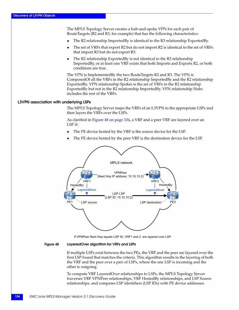
EMC Ionix MPLS Manager Version 3.1 Discovery Guide104
Discovery of L3VPN Objects
The MPLS Topology Server creates a hub-and-spoke VPN for each pair of RouteTargets (R2 and R3, for example) that has the following characteristics:
◆ The R2 relationship ImportedBy is identical to the R3 relationship ExportedBy.
◆ The set of VRFs that export R2 but do not import R2 is identical to the set of VRFs that import R3 but do not export R3.
◆ The R2 relationship ExportedBy is not identical to the R3 relationship ImportedBy, or at least one VRF exists that both Imports and Exports R2, or both conditions are true.
The VPN is ImplementedBy the two RouteTargets R2 and R3. The VPN is ComposedOf all the VRFs in the R2 relationship ImportedBy and the R2 relationship ExportedBy. VPN relationship Spokes is the set of VRFs in the R2 relationship ExportedBy but not in the R2 relationship ImportedBy. VPN relationship Hubs includes the rest of the VRFs.
L3VPN association with underlying LSPsThe MPLS Topology Server maps the VRFs of an L3VPN to the appropriate LSPs and then layers the VRFs over the LSPs.
As clarified in Figure 48 on page 104, a VRF and a peer VRF are layered over an LSP if:
◆ The PE device hosted by the VRF is the source device for the LSP.
◆ The PE device hosted by the peer VRF is the destination device for the LSP.
Figure 48 LayeredOver algorithm for VRFs and LSPs
If multiple LSPs exist between the two PEs, the VRF and the peer are layered over the first LSP found that matches the criteria. This algorithm results in the layering of both the VRF and the peer over a pair of LSPs, where the one LSP is incoming and the other is outgoing.
To compute VRF LayeredOver relationships to LSPs, the MPLS Topology Server traverses VRF VPNPeer relationships, VRF HostedBy relationships, and LSP Source relationships, and compares LSP identifiers (LSP IDs) with PE device addresses.
MPLS network
PE1
HostedBy
PE2
HostedBy
VPNPeer(Next Hop IP address: 10.10.10.2)
LDP LSP(LSP ID: 10.10.10.2)
LSP destinationLSP source
LayeredOver LayeredOver
VRF2VRF1
If VPNPeer Next Hop equals LSP ID, VRF1 and 2 are layered over LSP.
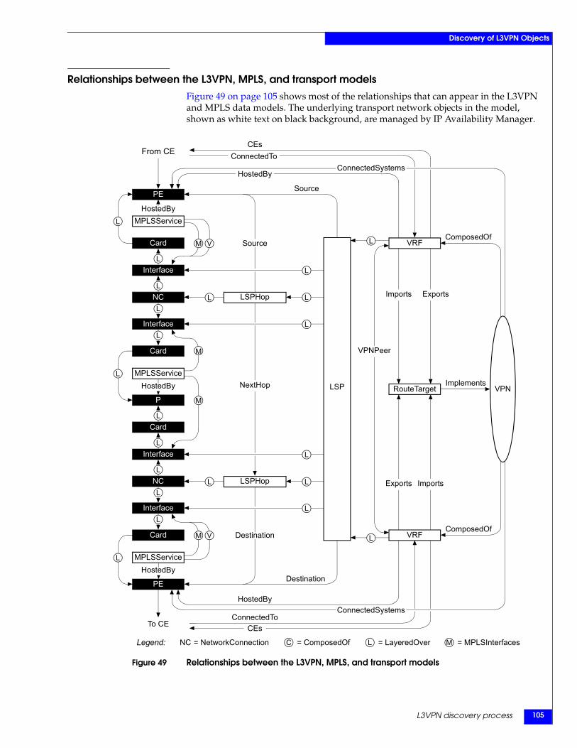
L3VPN discovery process 105
Discovery of L3VPN Objects
Relationships between the L3VPN, MPLS, and transport modelsFigure 49 on page 105 shows most of the relationships that can appear in the L3VPN and MPLS data models. The underlying transport network objects in the model, shown as white text on black background, are managed by IP Availability Manager.
Figure 49 Relationships between the L3VPN, MPLS, and transport models
HostedByMPLSService
PE
Interface
Card
From CE
To CE
L
L
Interface
Card
NC
L
L
HostedByMPLSService
P
Interface
Card
L
L
HostedBy
PE
Interface
Card
NC
L
L
L
L
L
L
M
L
L
M
L
Source
L
L
L
MPLSService
VRF
Implements
VPNPeer
LSP RouteTarget
Source
Exports
L
CEs
Destination
Exports Imports
M V
LSPHop
ComposedOf
ComposedOf
VPN
ConnectedTo
HostedBy
CEs
ConnectedTo
HostedBy
ConnectedSystems
ConnectedSystems
VRF
L
LSPHop
NextHop
L
L
Destination
Legend: = NetworkConnection C = ComposedOf L = LayeredOverNC M = MPLSInterfaces
Imports
M V

EMC Ionix MPLS Manager Version 3.1 Discovery Guide106
Discovery of L3VPN Objects
Preparing and Initiating Discovery 107
7
This chapter describes how to prepare and initiate discovery for an MPLS Manager deployment. It consists of the following sections:
◆ Preparing for discovery............................................................................................... 108◆ Initiating discovery ...................................................................................................... 109◆ Synchronizing with IP Availability Manager............................................................110◆ Synchronizing with the MPLS Topology Server.......................................................111◆ Specifying a different IP Availability Manager source ............................................114
Preparing andInitiating Discovery
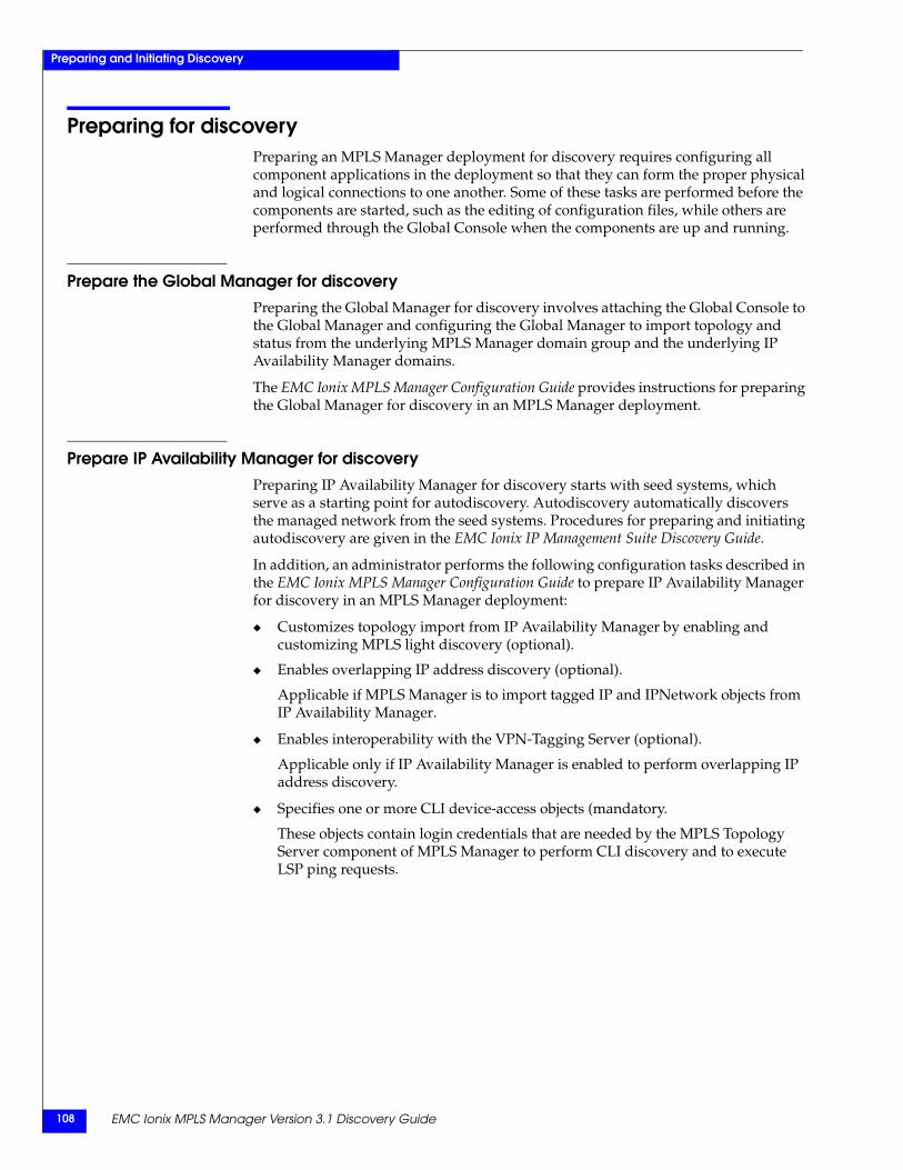
EMC Ionix MPLS Manager Version 3.1 Discovery Guide108
Preparing and Initiating Discovery
Preparing for discoveryPreparing an MPLS Manager deployment for discovery requires configuring all component applications in the deployment so that they can form the proper physical and logical connections to one another. Some of these tasks are performed before the components are started, such as the editing of configuration files, while others are performed through the Global Console when the components are up and running.
Prepare the Global Manager for discoveryPreparing the Global Manager for discovery involves attaching the Global Console to the Global Manager and configuring the Global Manager to import topology and status from the underlying MPLS Manager domain group and the underlying IP Availability Manager domains.
The EMC Ionix MPLS Manager Configuration Guide provides instructions for preparing the Global Manager for discovery in an MPLS Manager deployment.
Prepare IP Availability Manager for discoveryPreparing IP Availability Manager for discovery starts with seed systems, which serve as a starting point for autodiscovery. Autodiscovery automatically discovers the managed network from the seed systems. Procedures for preparing and initiating autodiscovery are given in the EMC Ionix IP Management Suite Discovery Guide.
In addition, an administrator performs the following configuration tasks described in the EMC Ionix MPLS Manager Configuration Guide to prepare IP Availability Manager for discovery in an MPLS Manager deployment:
◆ Customizes topology import from IP Availability Manager by enabling and customizing MPLS light discovery (optional).
◆ Enables overlapping IP address discovery (optional).
Applicable if MPLS Manager is to import tagged IP and IPNetwork objects from IP Availability Manager.
◆ Enables interoperability with the VPN-Tagging Server (optional).
Applicable only if IP Availability Manager is enabled to perform overlapping IP address discovery.
◆ Specifies one or more CLI device-access objects (mandatory.
These objects contain login credentials that are needed by the MPLS Topology Server component of MPLS Manager to perform CLI discovery and to execute LSP ping requests.
Initiating discovery 109
Preparing and Initiating Discovery
Prepare MPLS Manager for discoveryTo prepare MPLS Manager for its initial discovery, an administrator performs the following task:
Specifies one or more IP Availability Managers in the mpls.conf file.
When the MPLS Topology Server component of MPLS Manager starts up, it adds as topology sources the IP Availability Managers that are specified in the mpls.conf file, and imports topology and CLI device-access objects from the IP Availability Managers.
The EMC Ionix MPLS Manager Configuration Guide describes the mpls.conf and other MPLS Manager configuration files, and provides instructions for preparing MPLS Manager for discovery.
Initiating discoveryAfter preparing your MPLS Manager deployment for discovery, you initiate an IP Availability Manager discovery for each IP Availability Manager in the deployment. Then, you initiate an MPLS Manager discovery by starting the MPLS Manager component servers.
During startup, the MPLS Topology Server:
◆ Registers with the EMC Ionix Broker.
◆ Loads its .import (probe) and configuration files, including mpls.conf and mpls-tma.conf.
◆ Adds as a topology source each IP Availability Manager listed in the mpls.conf file.
◆ Creates in its repository an InChargeDomain object (INCHARGE-AM, for example) for each IP Availability Manager instance that is added as a topology source.
◆ Establishes a connection to each IP Availability Manager source and probes each source for router and switch topology and CLI device-access objects.
◆ Imports and stores in its repository the router and switch topology that is discovered by each IP Availability Manager source.
◆ Imports and stores in its repository the CLI device-access objects from each IP Availability Manager source that is exporting CLI device-access objects for MPLS Manager operation.
◆ Initiates its own discovery by sending SNMP polls and/or CLI commands to the router and switch devices to discover the MPLS and VPN information that is needed to build the MPLS and VPN topology.
Chapter 8, ”Understanding Discovery Results,” provides information about discovery errors and their solutions.
EMC Ionix MPLS Manager Version 3.1 Discovery Guide110
Preparing and Initiating Discovery
After initial discovery, and assuming that the StopAutoAMSync parameter in the mpls.conf file is FALSE (default), the MPLS Topology Server selectively imports topology from IP Availability Manager whenever IP Availability Manager completes a discovery cycle. “Synchronizing with IP Availability Manager” on page 110 describes how the MPLS Topology Server synchronizes its discovery with the discovery of IP Availability Manager.
“Synchronizing with the MPLS Topology Server” on page 111 describes how the MPLS Monitoring Server and the MPLS Analysis Server components of MPLS Manager synchronize their topology import with the discovery of the MPLS Topology Server.
Synchronizing with IP Availability ManagerAfter an IP Availability Manager is added as a topology source, the MPLS Topology Server starts two synchronization programs:
◆ One that probes the IP Availability Manager repository for router and switch topology
◆ One that probes the IP Availability Manager repository for CLI device-access objects
The synchronization programs are independent of one another.
Topology synchronizationThe topology synchronization program probes for topology immediately after an IP Availability Manager is added as a topology source, and then every time thereafter whenever:
◆ The IP Availability Manager completes a discovery cycle.
Note: Assumes StopAutoAMSync parameter in mpls.conf file is FALSE (default).
◆ The connection to IP Availability Manager is lost and then reestablished.
Each time that an IP Availability Manager completes a discovery cycle, the MPLS Topology Server performs the following incremental discovery:
◆ Compares the current IP Availability Manager topology with the previously imported topology.
◆ Whenever a new router or switch is found or an already known router or switch has a newer discovery timestamp, sends SNMP requests and/or CLI commands to that device to discover or rediscover the device’s MPLS and VPN objects.
◆ Adds those objects to the MPLS and VPN topology in its repository.
CLI device-access object synchronizationThe CLI device-access object synchronization program probes for CLI device-access objects immediately after an IP Availability Manager is added as a topology source, and then every time thereafter whenever:
◆ The CLI device-access objects have changed in the IP Availability Manager.
◆ The connection to IP Availability Manager is lost and then reestablished.
Synchronizing with the MPLS Topology Server 111
Preparing and Initiating Discovery
Each time that the MPLS Topology Server imports CLI device-access objects from an IP Availability Manager, it imports all of the CLI device-access objects. The import of CLI device-access objects does not trigger the import of topology from IP Availability Manager.
The EMC Ionix MPLS Manager Configuration Guide describes how to configure CLI device-access groups for MPLS Manager.
Synchronizing with the MPLS Topology ServerThe MPLS component servers of MPLS Manager may be started in any order, meaning that the MPLS Monitoring Server and the MPLS Analysis Server may be started before or after the MPLS Topology Server performs its initial discovery.
Whenever the MPLS Monitoring Server and the MPLS Analysis Server are started, the MPLS Manager autoconfiguration program, described in the EMC Ionix MPLS Manager Configuration Guide, automatically adds the MPLS Topology Server as a topology source to the MPLS monitoring and analysis servers, and creates an InChargeDomain object (INCHARGE-MPLS-TOPOLOGY, for example) in their repositories.
After the MPLS Topology Server is added as a topology source, the MPLS Monitoring Server and the MPLS Analysis Server each start a synchronization program that probes the MPLS Topology Server repository for device, MPLS, and VPN topology. The synchronization program probes for topology information immediately after the MPLS Topology Server is added as a topology source, and then every time thereafter whenever:
◆ The MPLS Topology Server completes a discovery cycle.
◆ The connection to the MPLS Topology Server is lost and then reestablished.
If the MPLS Topology Server is not running when the MPLS Monitoring Server/ MPLS Analysis Server starts up, the synchronization program periodically attempts to probe for the topology. When the MPLS Topology Server becomes available, the probing succeeds.
During the probing of topology, the MPLS monitoring and analysis servers also learn the names of their proxy (status) sources: The MPLS Monitoring Server learns the names of the IP Availability Managers that are added as topology sources to the MPLS Topology Server, and the MPLS Analysis Server learns the name of the MPLS Monitoring Server.
MPLS Monitoring Server synchronizationAfter the MPLS Topology Server adds an IP Availability Manager as a topology source, imports topology, and performs its own discovery, the MPLS Monitoring Server responds by performing the following tasks:
1. Imports from the MPLS Topology Server and stores in its repository:
• A subset of device, MPLS, and VPN topology (identified in “Imported topology subsets” on page 113), to be used for monitoring purposes.
• An InChargeDomain object (INCHARGE-AM, for example) that represents the IP Availability Manager topology source.
2. Starts a remote (proxy) accessor probe.
EMC Ionix MPLS Manager Version 3.1 Discovery Guide112
Preparing and Initiating Discovery
The probe automatically adds the IP Availability Manager as a proxy source to the MPLS Monitoring Server: It sets up a remote-repository instrumentation arrangement in which the MPLS Monitoring Server periodically retrieves from the IP Availability Manager repository the instrumentation attribute values of the router and switch objects that are managed by IP Availability Manager.
To associate a router or switch object in the repository of the MPLS Monitoring Server repository with its proxy source, the object’s ServiceName attribute is set to the name of the IP Availability Manager. For a router or switch object that is monitored by multiple proxy sources, the object’s ServiceName attribute is set to the name of the last added active IP Availability Manager.
Thereafter, at startup or whenever the connection to the MPLS Topology Server is lost and then reestablished, the MPLS Monitoring Server re-imports topology from the MPLS Topology Server and re-runs the proxy probe.
Also, whenever the MPLS Monitoring Server imports topology from the MPLS Topology Server, the MPLS Topology Server stores the name of the MPLS Monitoring Server (INCHARGE-MPLS-MONITORING, for example) as a reference for the MPLS Analysis Server.
MPLS Analysis Server synchronizationAfter the MPLS Topology Server adds an IP Availability Manager as a topology source, imports topology, and performs its own discovery, the MPLS Analysis Server responds by performing the following tasks:
1. Imports from the MPLS Topology Server and stores in its repository a subset of device, MPLS, and VPN topology (identified in “Imported topology subsets” on page 113), to be used for analysis purposes. It also imports the reference (INCHARGE-MPLS-MONITORING, for example) identifying the name of the MPLS Monitoring Server.
2. Starts a remote (proxy) accessor probe.
The probe creates an InChargeDomain object (INCHARGE-MPLS-MONITORING, for example) that has the instance name of the MPLS Monitoring Server and automatically adds the MPLS Monitoring Server as a proxy source to the MPLS Analysis Server: It sets up a remote-repository instrumentation arrangement in which the MPLS Analysis Server retrieves from the MPLS Monitoring Server repository the instrumentation attribute values of the device, MPLS, and VPN objects when performing a correlation analysis cycle (every 30 seconds by default).
To associate a device, MPLS, or VPN object in the repository of the MPLS Analysis Server with its proxy source, the object’s ServiceName attribute is set to the name of the MPLS Monitoring Server.
Thereafter, at startup or whenever the connection to the MPLS Topology Server is lost and then reestablished, the MPLS Analysis Server re-imports topology from the MPLS Topology Server and re-runs the proxy probe.
Note that if the MPLS Analysis Server imports its initial topology before the MPLS Monitoring Server imports its initial topology, the MPLS Analysis Server will not be able to determine its MPLS Monitoring Server proxy source. However, as soon as the MPLS Monitoring server import its topology, the MPLS Topology Server will send a proxy update message to the MPLS Analysis Server, and the MPLS Analysis Server will add the MPLS Monitoring Server as a proxy source.
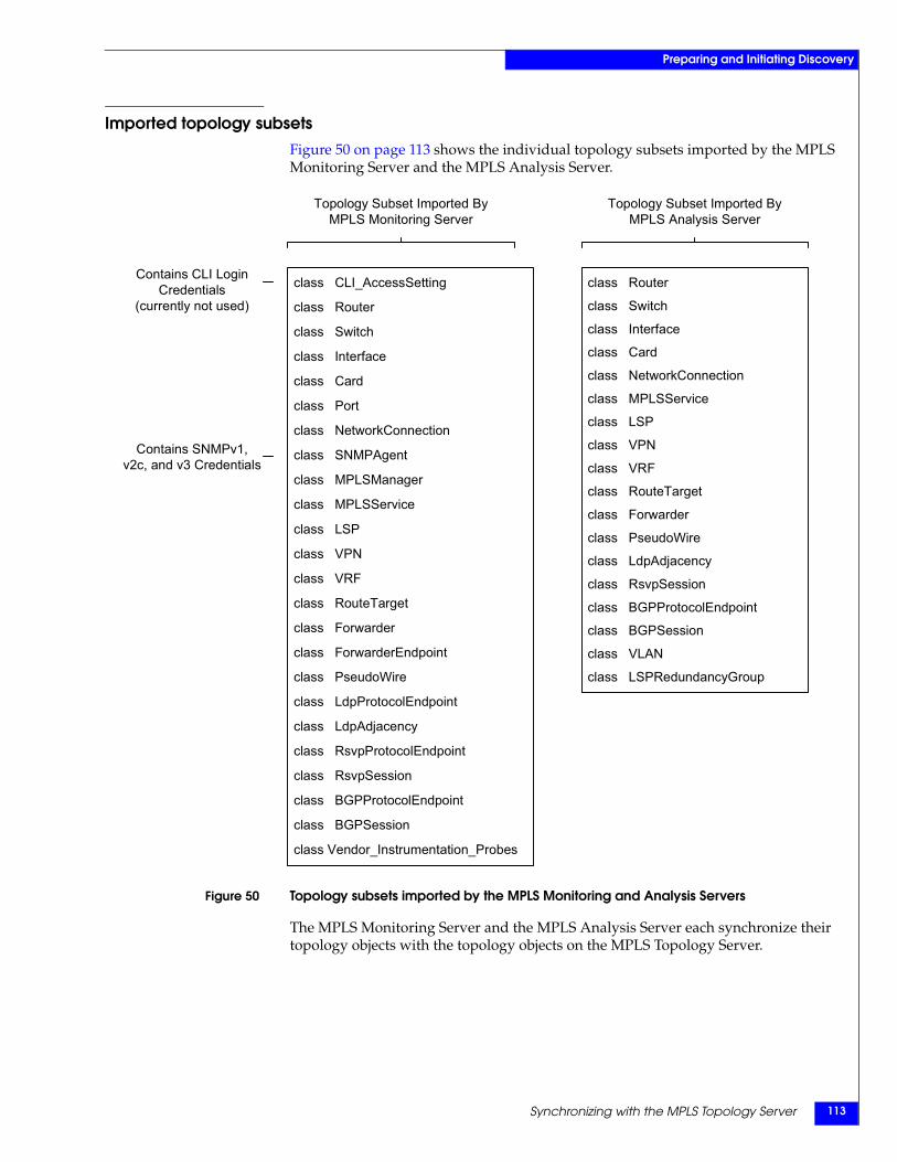
Synchronizing with the MPLS Topology Server 113
Preparing and Initiating Discovery
Imported topology subsetsFigure 50 on page 113 shows the individual topology subsets imported by the MPLS Monitoring Server and the MPLS Analysis Server.
Figure 50 Topology subsets imported by the MPLS Monitoring and Analysis Servers
The MPLS Monitoring Server and the MPLS Analysis Server each synchronize their topology objects with the topology objects on the MPLS Topology Server.
class CLI_AccessSetting
class Router
class Switch
class Interface
class Card
class Port
class NetworkConnection
class SNMPAgent
class MPLSManager
class MPLSService
class LSP
class VPN
class VRF
class RouteTarget
class Forwarder
class ForwarderEndpoint
class PseudoWire
class LdpProtocolEndpoint
class LdpAdjacency
class RsvpProtocolEndpoint
class RsvpSession
class BGPProtocolEndpoint
class BGPSession
class Vendor_Instrumentation_Probes
class Router
class Switch
class Interface
class Card
class NetworkConnection
class MPLSService
class LSP
class VPN
class VRF
class RouteTarget
class Forwarder
class PseudoWire
class LdpAdjacency
class RsvpSession
class BGPProtocolEndpoint
class BGPSession
class VLAN
class LSPRedundancyGroup
Topology Subset Imported ByMPLS Monitoring Server
Topology Subset Imported ByMPLS Analysis Server
Contains CLI LoginCredentials
(currently not used)
Contains SNMPv1, v2c, and v3 Credentials
EMC Ionix MPLS Manager Version 3.1 Discovery Guide114
Preparing and Initiating Discovery
Other synchronizations for the MPLS Monitoring ServerFrom the MPLS Topology Server, the MPLS Monitoring Server also imports CLI device-access objects, polling objects, and remote ping objects. The MPLS Monitoring Server synchronizes its CLI device-access objects with the CLI device-access objects on the MPLS Topology Server, synchronizes its polling objects with the polling objects on the MPLS Topology Server, and synchronizes its remote ping objects with the remote ping objects on the MPLS Topology Server.
Note: Currently, the CLI device-access objects on the MPLS Monitoring Server are not used.
The topology, CLI device-access, polling, and remote ping synchronizations are independent of one another, meaning that a synchronization in progress does not trigger other synchronizations. As an example, when the MPLS Monitoring Server detects that its polling objects are out-of-date, it re-imports the polling objects from the MPLS Topology Server but does not re-import the topology, CLI device-access, or remote ping objects from the MPLS Topology Server.
The EMC Ionix MPLS Manager Configuration Guide describes how to configure CLI device-access groups, polling groups, and remote ping groups for MPLS Manager.
Specifying a different IP Availability Manager sourceYou can specify a different IP Availability Manager source for the MPLS Topology Server by performing the following two steps:
1. In the mpls.conf file, replace the IP Availability Manager entry with the new entry.
2. Stop the MPLS Topology Server, the MPLS Monitoring Server, and the MPLS Analysis Server and then restart them with startup command lines that contain the --norestore option.
Including the --norestore option in the startup command line will start the MPLS servers without restoring any saved objects from their respective repository files. Repository files are located in the BASEDIR/smarts/local/repos/icf directory. This mode of startup deletes from the repository the topology and instrumentation objects that are associated with the current IP Availability Manager source.
Because the MPLS service startup commands created during the MPLS Manager installation do not contain the --norestore option, you will need to do one of the following:
◆ Temporarily modify the service startup commands by substituting --ignore-restore-errors with --norestore.
◆ Create new service startup commands or new native startup commands that contain the --norestore option.
Specifying a different IP Availability Manager source 115
Preparing and Initiating Discovery
Procedure for specifying a different IP Availability Manager sourceWhat follows is an example procedure of specifying a different IP Availability Manager source. The procedure replaces an IP Availability Manager source named INCHARGE-AM with a source named INCHARGE-AM3. Native startup commands that contain the --norestore option are included in the procedure.
To specify a different IP Availability Manager source named INCHARGE-AM3:
1. Go to the BASEDIR/smarts/bin directory in the MPLS Management Suite installation area and type the following command to open the mpls.conf file:
sm_edit conf/mpls-t/mpls.conf
Press Enter.
2. Find the section, Instances of AM Server, and then find the following five lines:
InChargeDomain::InChargeDomain_INCHARGE-AM {Type = "AM"DomainName = "INCHARGE-AM"DisplayName = "INCHARGE-AM"
}
3. On the InChargeDomain, DomainName, and DisplayName lines, change INCHARGE-AM to INCHARGE-AM3:
InChargeDomain::InChargeDomain-AM3 {Type = "AM"DomainName = "AM3"DisplayName = "AM3"
}
4. Save and close the file.
The modified version of the mpls.conf file is saved to the BASEDIR/smarts/local/conf/mpls-t directory.
5. Enter the following three commands from BASEDIR/smarts/bin to stop the MPLS Topology Server, the MPLS Monitoring Server, and the MPLS Analysis Server:
sm_service stop --force ic-mpls-topology
sm_service stop --force ic-mpls-monitoring
sm_service stop --force ic-mpls-analysis
On a Windows system, you can also stop the MPLS servers by selecting Start > Programs > Administrative Tools > Services to launch the Services window, then right-clicking the service names of the MPLS servers (right-clicking EMC Ionix MPLS Topology Server, for example), and then selecting Stop from the pop-up menus.
EMC Ionix MPLS Manager Version 3.1 Discovery Guide116
Preparing and Initiating Discovery
6. Enter the following native command from BASEDIR/smarts/bin to start the MPLS Topology Server:
On a Windows system:start sm_server --name=INCHARGE-MPLS-TOPOLOGY --config=mpls-t --norestore --output
On a Windows system, including "start" at the beginning of the command line launches another command-line window in which the EMC Ionix process starts and runs until the process is terminated. Launching a separate window leaves the original command-line window free to receive more commands.
On a UNIX system:sm_server --name=INCHARGE-MPLS-TOPOLOGY --config=mpls-t --norestore --output --daemon
On a UNIX system, including the "--daemon" option in the command line starts the EMC Ionix process running in the background, leaving the original UNIX shell free to receive more commands. The --daemon option is not a valid option for a Windows system.
7. Enter the following native command from BASEDIR/smarts/bin to start the MPLS Monitoring Server:
On a Windows system:start sm_server --name=INCHARGE-MPLS-MONITORING --config=mpls-m --norestore --output
On a UNIX system:sm_server --name=INCHARGE-MPLS-MONITORING --config=mpls-m --norestore --output --daemon
8. Enter the following native command from BASEDIR/smarts/bin to start the MPLS Analysis Server:
On a Windows system:start sm_server --name=INCHARGE-MPLS-ANALYSIS --config=mpls-a --norestore --output
On a UNIX system:sm_server --name=INCHARGE-MPLS-ANALYSIS --config=mpls-a --norestore --output --daemon
At startup, the MPLS Topology Server reads the mpls.conf file, loads the configuration information to its repository, and imports router and switch topology and CLI device-access objects from the IP Availability Manager sources that are specified in the mpls.conf file. In this example, the MPLS Topology Server will import new topology from the IP Availability Manager named INCHARGE-AM3.
Understanding Discovery Results 117
8
This chapter describes MPLS Manager discovery results, discovery error resolutions, and the Pending Elements list. It consists of the following sections:
◆ Discovery results ...........................................................................................................118◆ Discovery error resolutions .........................................................................................119◆ Error message formatting ........................................................................................... 122◆ Examples of error messages in CLI log files............................................................. 124◆ Pending Elements list .................................................................................................. 125
UnderstandingDiscovery Results
EMC Ionix MPLS Manager Version 3.1 Discovery Guide118
Understanding Discovery Results
Discovery resultsWhen the MPLS Topology Server component of MPLS Manager attempts to discover MPLS and VPN topology by probing a router or switch device, one of the following results occurs:
◆ Discovery successfully completes, and the MPLS and VPN topology objects that are discovered by probing the device are added to the managed topology.
◆ Discovery starts but communication is lost between the MPLS Topology Server and the device.
◆ Discovery starts but the device does not respond to SNMP polls and/or CLI commands.
◆ Discovery starts but one or more of the MPLS Topology Server probes encounters an error during the discovery process.
◆ Discovery is unable to start or successfully complete.
Successful discoveryWhen the probing of a device for MPLS and VPN topology information is successful, an object is created in the MPLS Topology Server repository for each discovered MPLS or VPN topology element.
Unsuccessful discoveryIf the probing of a device for MPLS and VPN topology information does not complete successfully, an entry for that device is placed on the MPLS Topology Server’s Pending Elements list. “Pending Elements list” on page 125 provides information about the Pending Elements list and the Discovery Progress window in which it appears.
Discovery error resolutions 119
Understanding Discovery Results
Discovery error resolutionsYou use a number of means to resolve errors that might occur during MPLS Manager discovery, including the checking of the following sources:
◆ Discovery Progress window
◆ Log files
You open the Domain Manager Administration Console view of the Global Console to check the Discovery Progress window and the Pending Elements list.
Note: The MPLS Topology Server does not notify discovery errors, which means that discovery errors do not appear in the Notification Log Console view of a Global Console attached to the Global Manager.
Open the Domain Manager Administration ConsoleThe Global Console is a collection of many consoles, or console views, two of which are the Domain Manager Administration Console and the Global Manager Administration Console. The consoles enable administrators to manage EMC Ionix Domain Managers and Global Managers.
User accounts and passwordsAttaching the Global Console to a Domain Manager (such as MPLS Manager) or to a Global Manager requires an EMC Ionix user account. The default user accounts are as follows:
◆ Administration account:
• username: admin
• password: changeme
◆ Operator account:
• username: oper
• password: oper
For users logged on with an administration account, the Global Console includes a Configure menu. This menu enables administrators to open the Domain Manager Administration Console and the Global Manager Administration Console.
The EMC Smarts System Administration Guide provides information about changing the password for the default administration account (recommended) and configuring access privileges. The EMC Ionix Service Assurance Manager Configuration Guide provides information about configuring permissions to perform specific console operations.
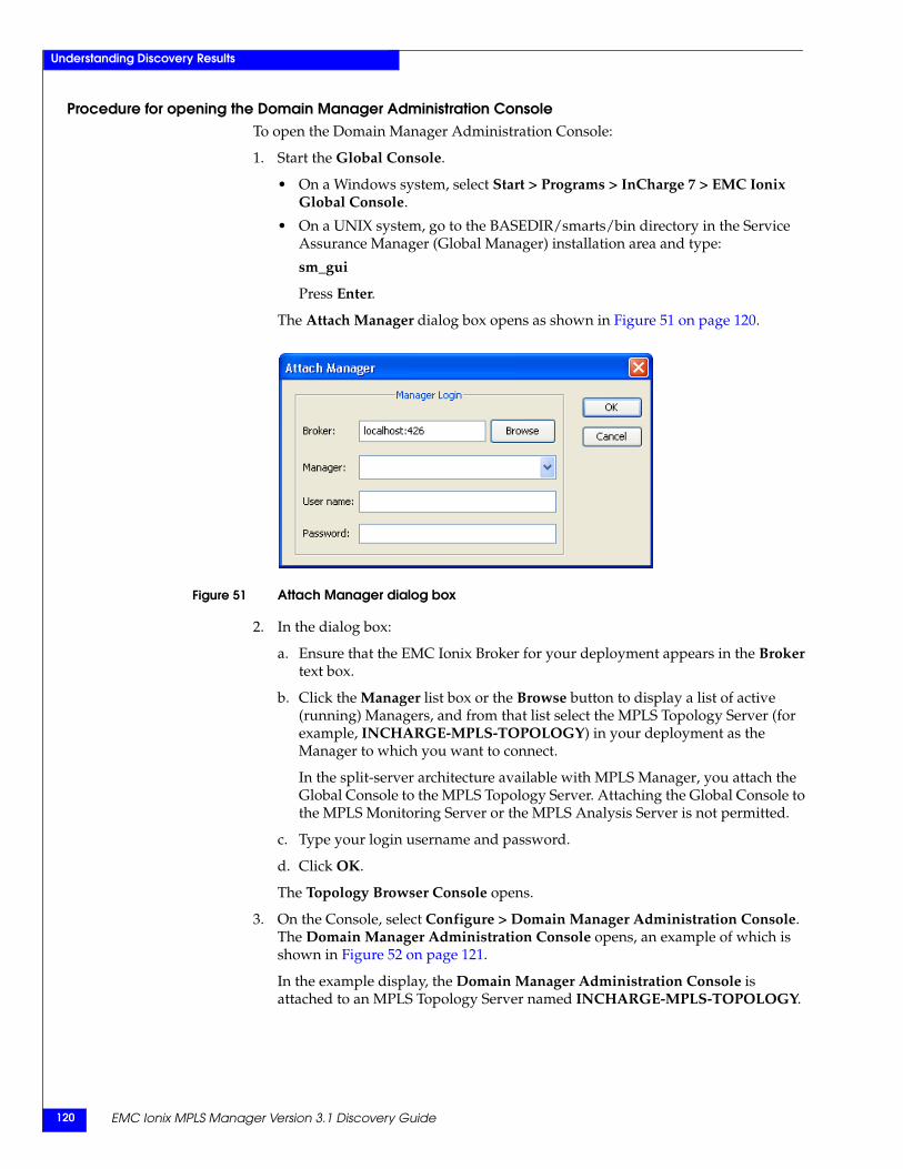
EMC Ionix MPLS Manager Version 3.1 Discovery Guide120
Understanding Discovery Results
Procedure for opening the Domain Manager Administration ConsoleTo open the Domain Manager Administration Console:
1. Start the Global Console.
• On a Windows system, select Start > Programs > InCharge 7 > EMC Ionix Global Console.
• On a UNIX system, go to the BASEDIR/smarts/bin directory in the Service Assurance Manager (Global Manager) installation area and type:
sm_gui
Press Enter.
The Attach Manager dialog box opens as shown in Figure 51 on page 120.
Figure 51 Attach Manager dialog box
2. In the dialog box:
a. Ensure that the EMC Ionix Broker for your deployment appears in the Broker text box.
b. Click the Manager list box or the Browse button to display a list of active (running) Managers, and from that list select the MPLS Topology Server (for example, INCHARGE-MPLS-TOPOLOGY) in your deployment as the Manager to which you want to connect.
In the split-server architecture available with MPLS Manager, you attach the Global Console to the MPLS Topology Server. Attaching the Global Console to the MPLS Monitoring Server or the MPLS Analysis Server is not permitted.
c. Type your login username and password.
d. Click OK.
The Topology Browser Console opens.
3. On the Console, select Configure > Domain Manager Administration Console. The Domain Manager Administration Console opens, an example of which is shown in Figure 52 on page 121.
In the example display, the Domain Manager Administration Console is attached to an MPLS Topology Server named INCHARGE-MPLS-TOPOLOGY.
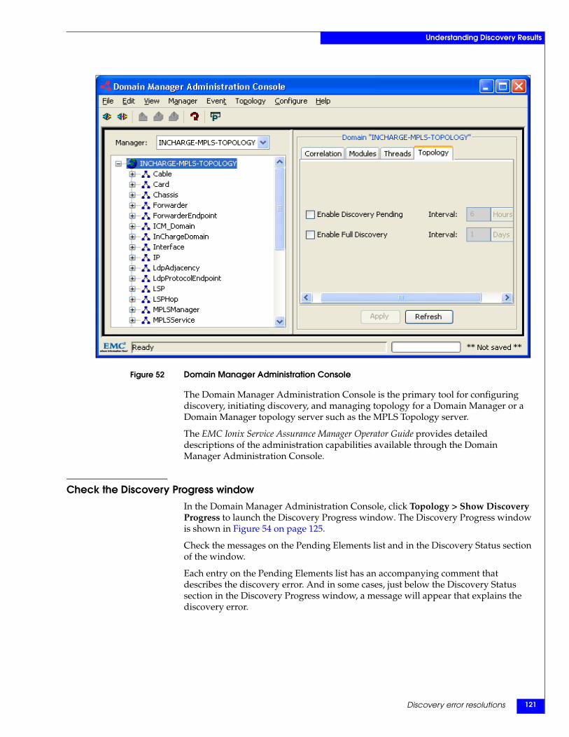
Discovery error resolutions 121
Understanding Discovery Results
Figure 52 Domain Manager Administration Console
The Domain Manager Administration Console is the primary tool for configuring discovery, initiating discovery, and managing topology for a Domain Manager or a Domain Manager topology server such as the MPLS Topology server.
The EMC Ionix Service Assurance Manager Operator Guide provides detailed descriptions of the administration capabilities available through the Domain Manager Administration Console.
Check the Discovery Progress windowIn the Domain Manager Administration Console, click Topology > Show Discovery Progress to launch the Discovery Progress window. The Discovery Progress window is shown in Figure 54 on page 125.
Check the messages on the Pending Elements list and in the Discovery Status section of the window.
Each entry on the Pending Elements list has an accompanying comment that describes the discovery error. And in some cases, just below the Discovery Status section in the Discovery Progress window, a message will appear that explains the discovery error.
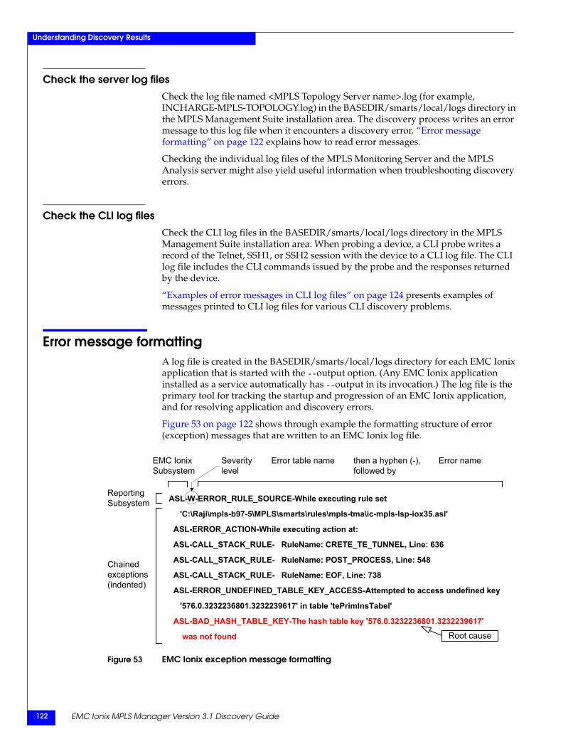
EMC Ionix MPLS Manager Version 3.1 Discovery Guide122
Understanding Discovery Results
Check the server log filesCheck the log file named <MPLS Topology Server name>.log (for example, INCHARGE-MPLS-TOPOLOGY.log) in the BASEDIR/smarts/local/logs directory in the MPLS Management Suite installation area. The discovery process writes an error message to this log file when it encounters a discovery error. “Error message formatting” on page 122 explains how to read error messages.
Checking the individual log files of the MPLS Monitoring Server and the MPLS Analysis server might also yield useful information when troubleshooting discovery errors.
Check the CLI log filesCheck the CLI log files in the BASEDIR/smarts/local/logs directory in the MPLS Management Suite installation area. When probing a device, a CLI probe writes a record of the Telnet, SSH1, or SSH2 session with the device to a CLI log file. The CLI log file includes the CLI commands issued by the probe and the responses returned by the device.
“Examples of error messages in CLI log files” on page 124 presents examples of messages printed to CLI log files for various CLI discovery problems.
Error message formattingA log file is created in the BASEDIR/smarts/local/logs directory for each EMC Ionix application that is started with the --output option. (Any EMC Ionix application installed as a service automatically has --output in its invocation.) The log file is the primary tool for tracking the startup and progression of an EMC Ionix application, and for resolving application and discovery errors.
Figure 53 on page 122 shows through example the formatting structure of error (exception) messages that are written to an EMC Ionix log file.
Figure 53 EMC Ionix exception message formatting
ASL-W-ERROR_RULE_SOURCE-While executing rule set
'C:\Raji\mpls-b97-5\MPLS\smarts\rules\mpls-tma\ic-mpls-lsp-iox35.asl'
ASL-ERROR_ACTION-While executing action at:
ASL-CALL_STACK_RULE- RuleName: CRETE_TE_TUNNEL, Line: 636
ASL-CALL_STACK_RULE- RuleName: POST_PROCESS, Line: 548
ASL-CALL_STACK_RULE- RuleName: EOF, Line: 738
ASL-ERROR_UNDEFINED_TABLE_KEY_ACCESS-Attempted to access undefined key
'576.0.3232236801.3232239617' in table 'tePrimInsTabel'
ASL-BAD_HASH_TABLE_KEY-The hash table key '576.0.3232236801.3232239617'
was not found
ReportingSubsystem
Chainedexceptions(indented)
EMC IonixSubsystem
Severitylevel
Error nameError table name then a hyphen (-),followed by
Root cause
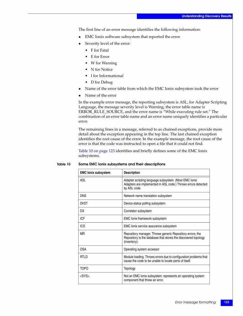
Error message formatting 123
Understanding Discovery Results
The first line of an error message identifies the following information:
◆ EMC Ionix software subsystem that reported the error
◆ Severity level of the error:
• F for Fatal
• E for Error
• W for Warning
• N for Notice
• I for Informational
• D for Debug
◆ Name of the error table from which the EMC Ionix subsystem took the error
◆ Name of the error
In the example error message, the reporting subsystem is ASL, for Adapter Scripting Language, the message severity level is Warning, the error table name is ERROR_RULE_SOURCE, and the error name is “While executing rule set.” The combination of an error table name and an error name uniquely identifies a particular error.
The remaining lines in a message, referred to as chained exceptions, provide more detail about the exception appearing in the top line. The last chained exception identifies the root cause of the error. In the example message, the root cause of the error is that the code was instructed to open a file that it could not find.
Table 10 on page 123 identifies and briefly defines some of the EMC Ionix subsystems.
Table 10 Some EMC Ionix subsystems and their descriptions
EMC Ionix subsystem Description
ASL Adapter scripting language subsystem. (Most EMC Ionix Adapters are implemented in ASL code.) Throws errors detected by ASL code.
DNS Network name translation subsystem
DVST Device status polling subsystem
DX Correlator subsystem
ICF EMC Ionix framework subsystem
ICS EMC Ionix service assurance subsystem
MR Repository manager. Throws generic Repository errors; the Repository is the database that stores the discovered topology (inventory).
OSA Operating system accessor
RTLD Module loading. Throws errors due to configuration problems that cause the code to be unable to locate parts of itself.
TOPO Topology
<SYS> Not an EMC Ionix subsystem; represents an operating system component that threw an error.
EMC Ionix MPLS Manager Version 3.1 Discovery Guide124
Understanding Discovery Results
Examples of error messages in CLI log filesThe format for naming a CLI log file is:
CLI-<device vendor>-<device name>.txt
where <device vendor> is CISCO, HUAWEI, JUNIPER6, or ERX.
Two example CLI log file names are:
CLI-CISCO-qa-gw15.txtCLI-JUNIPER6-10.9.130.121.txt
Typically, one of four outcomes is recorded in a CLI log file:
◆ Outcome 1: Target device does not support Telnet, SSH1, or SSH2; for a target device named "qa-gw15," an example of this error is:
Starting to telnet qa-gw15.Error: Unable to connect to remote host qa-gw15 :
Connection refused
◆ Outcome 2: Target device supports Telnet, SSH1, or SSH2, but the login credentials (username, user password, enable password) are incorrect for the device; for a target device named "10.9.130.121," an example of this error is:
Starting to telnet 10.9.130.121.Error: Unable to login to 10.9.130.121.
◆ Outcome 3: Target device does not match any CLI device-access group:
***Warning: Missing CLI_AccessSetting for <device name>.
◆ Outcome 4: Discovery successfully completes, and the MPLS and VPN topology objects discovered by probing the device are added to the managed topology; for example:
Starting to telnet qa-vplsce1....(What CLI commands are invoked depends on the vendor and the configuration of the target device. The CLI command set for each supported vendor are identified in Appendix B, “CLI Commands Invoked for Discovery and LSP Ping.”)
If debug tracing is enabled, the following new line of information appears as the first line in the CLI log file:
Information: running the perl_commands.pl at <device vendor> (for example, CISCO) : <device name> (for example, qa-gw8).
To enable debug tracing, set the “debug” flag in the BASEDIR/smarts/conf/mpls-t/perl-cli.conf file to a nonzero value. For example:
$vars{"debug"} = 1;
The EMC Ionix MPLS Manager Configuration Guide describes the parameters in the perl-cli.conf file and provides instructions for modifying the parameters.
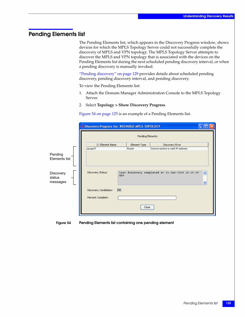
Pending Elements list 125
Understanding Discovery Results
Pending Elements listThe Pending Elements list, which appears in the Discovery Progress window, shows devices for which the MPLS Topology Server could not successfully complete the discovery of MPLS and VPN topology. The MPLS Topology Server attempts to discover the MPLS and VPN topology that is associated with the devices on the Pending Elements list during the next scheduled pending discovery interval, or when a pending discovery is manually invoked.
“Pending discovery” on page 129 provides details about scheduled pending discovery, pending discovery interval, and pending discovery.
To view the Pending Elements list:
1. Attach the Domain Manager Administration Console to the MPLS Topology Server.
2. Select Topology > Show Discovery Progress.
Figure 54 on page 125 is an example of a Pending Elements list.
Figure 54 Pending Elements list containing one pending element
Discoverystatusmessages
PendingElements list
241
qa-gw27 Router Cannot resolve to valid IP address
EMC Ionix MPLS Manager Version 3.1 Discovery Guide126
Understanding Discovery Results
Information provided by the Pending Elements listThe Pending Elements list contains three columns that provide the following information for a pending element:
◆ Element Name: Name of the device (probe instance) for which the probing of MPLS or VPN topology information did not complete successfully. The name contains the assigned display name of the device.
◆ Element Type: Name of the probe (device type) that probes the device identified in the Element Name field.
◆ Discovery Error: Comment describing why the device identified in the Element Name field is on the Pending Elements list.
To see all of the text associated with a particular element name, element type, or discovery error, position the mouse pointer over the element name, element type, or discovery error.
Management of individual pending element entriesIf you right-click an element on the Pending Elements list, a pop-up menu appears listing the following three selections: Remove, Rediscovery, and Show Discovery Time.
◆ Select Remove to remove the selected element from the Pending Elements list.
◆ Select Rediscovery to initiate an immediate discovery of the selected element.
◆ Select Show Discovery Time to view the last time that the selected element was discovered. If Show Discovery Time is unavailable (dimmed), the element has yet to be discovered.

Invoking Full or Pending Discovery 127
9
This chapter explains how to invoke full or pending discovery for MPLS Manager. It consists of the following sections.
◆ Discovery methods ...................................................................................................... 128◆ Full discovery ............................................................................................................... 128◆ Pending discovery........................................................................................................ 129
Invoking Full orPending Discovery
EMC Ionix MPLS Manager Version 3.1 Discovery Guide128
Invoking Full or Pending Discovery
Discovery methodsMPLS Manager, like all EMC Ionix Domain Managers, supports two methods of discovery:
◆ Full discovery
◆ Pending discovery
Either method can be invoked automatically or manually.
Full discoveryDuring the initial full discovery, the MPLS Topology Server component of MPLS Manager populates its repository with router and switch topology from IP Availability Manager, and then probes the devices to discover MPLS and VPN topology. The initial full discovery occurs when an IP Availability Manager is added as a source to the MPLS Topology Server, as explained in “Initiating discovery” on page 109.
Thereafter, whenever an IP Availability Manager source completes a discovery (an initial discovery, a full discovery, a pending discovery, or a single-device discovery), the MPLS Topology Server performs an incremental discovery as described in “Topology synchronization” on page 110.
Automatic full discoveryAutomatic full discovery reveals any changes in the configuration or connectivity of a device and keeps the topology current.
The parameters that control automatic full discovery are located on the Topology tab of the Domain Manager Administration Console. By default, automatic full discovery is disabled for the MPLS Topology Server.
Automatic full discovery should be enabled and scheduled for the one or more IP Availability Manager sources, not for the MPLS Topology Server. That way, whenever an IP Availability Manager source performs an automatic full discovery, the MPLS Topology Server performs an automatic full discovery.
Also, when you configure automatic full discovery, say weekly or daily, you should schedule the full discovery during off hours (5 A.M., for example). Running the discovery more often will provide a more accurate MPLS and VPN topology, but will also cost more in terms of network and system resources.
The EMC Ionix IP Management Suite Discovery Guide provides instructions for enabling and scheduling automatic full discovery for IP Availability Manager.
Manual full discoveryAs with automatic full discovery, manual full discovery should be performed at the IP Availability Manager sources, not at the MPLS Topology Server. Performing a manual full discovery at the IP Availability Manager will trigger a full discovery at the MPLS Topology Server.
The EMC Ionix IP Management Suite Discovery Guide provides instructions for performing manual full discovery for IP Availability Manager.
Pending discovery 129
Invoking Full or Pending Discovery
Pending discoveryDuring a pending discovery, the MPLS Topology Server attempts to discover MPLS and VPN topology by probing the devices on the Pending Elements list. The Pending Elements list contains the names of the devices that initially could not be discovered by the MPLS Topology Server.
You can view the Pending Elements list at any time by selecting Topology > Show Discovery Progress from the Domain Manager Administration Console. “Pending Elements list” on page 125 describes the various aspects of the Pending Elements list.
Automatic pending discoveryScheduling an automatic pending discovery determines how often the MPLS Topology Server attempts to discover MPLS topology by probing the devices on the Pending Elements list.
The parameters that control automatic pending discovery are located on the Topology tab of the Domain Manager Administration Console. By default, automatic pending discovery is disabled.
The pending discovery interval is counted from the time when the MPLS Topology Server is started. So, if the pending discovery interval is set to six hours and the MPLS Topology Server is started at 5 A.M., the pending discovery will occur every six hours thereafter, that is, at 11 A.M., at 5 P.M., at 11 P.M., and so on.
To enable automatic pending discovery and to specify a pending discovery interval:
1. Attach the Domain Manager Administration Console to the MPLS Topology Server.
Instructions for opening the Domain Manager Administration Console are presented in “Open the Domain Manager Administration Console” on page 119.
2. In the left panel of the Domain Manager Administration Console, click the MPLS Topology Server name to display a multiple-tab window in the right panel of the console.
3. Select the Topology tab.
4. Click the Enable Discovery Pending checkbox.
5. Type a value in the Interval field for pending discovery and select a time interval (Seconds, Minutes, Hours, or Days) from the list. Ensure that the interval is equal to or greater than five minutes.
6. Click Apply.

EMC Ionix MPLS Manager Version 3.1 Discovery Guide130
Invoking Full or Pending Discovery
Manual pending discoveryManually initiating a pending discovery for the MPLS Topology Server can be done from the Domain Manager Administration Console or from the command line.
Invoking pending discovery manually from the consoleFrom the Domain Manager Administration Console, you can use any of the following methods to manually invoke a pending discovery:
◆ To discover MPLS and VPN topology by probing all devices on the Pending Elements list, select Topology > Discover Pending.
◆ To discover MPLS and VPN topology by probing a single device on the Pending Elements list, right-click the device on the Pending Elements list and then select Rediscover from the pop-up menu.
Invoking pending discovery from the command lineFrom the command line, you can invoke a pending discovery by using the dmctl utility.
To do so, go to the BASEDIR/smarts/bin directory in the MPLS Management Suite installation area and invoke the following command on one line:
dmctl -s <MPLS Topology Server instance name> invoke ICF_TopologyManager::ICF-TopologyManager discoverPending
For example
dmctl -s INCHARGE-MPLS-TOPOLOGY invoke ICF_TopologyManager::ICF-TopologyManager discoverPending
When prompted for a username and password, specify an administration account; for example, admin and changeme. The dmctl utility is described in the HTML pages located in the BASEDIR/smarts/doc/html/usage directory of the MPLS Management Suite installation area.

MIBs Accessed for Discovery and Remote Ping 131
A
This appendix identifies the SNMP MIBs accessed by MPLS Manager to discover MPLS and VPN topology and to perform remote pings. It consists of the following sections:
◆ SNMP versions supported.......................................................................................... 132◆ MIBs accessed for MPLS discovery ........................................................................... 132◆ MIBs accessed for L2VPN discovery......................................................................... 135◆ MIBs accessed for L3VPN discovery......................................................................... 137◆ MIBs accessed for remote ping................................................................................... 138
MIBs Accessed forDiscovery and
Remote Ping
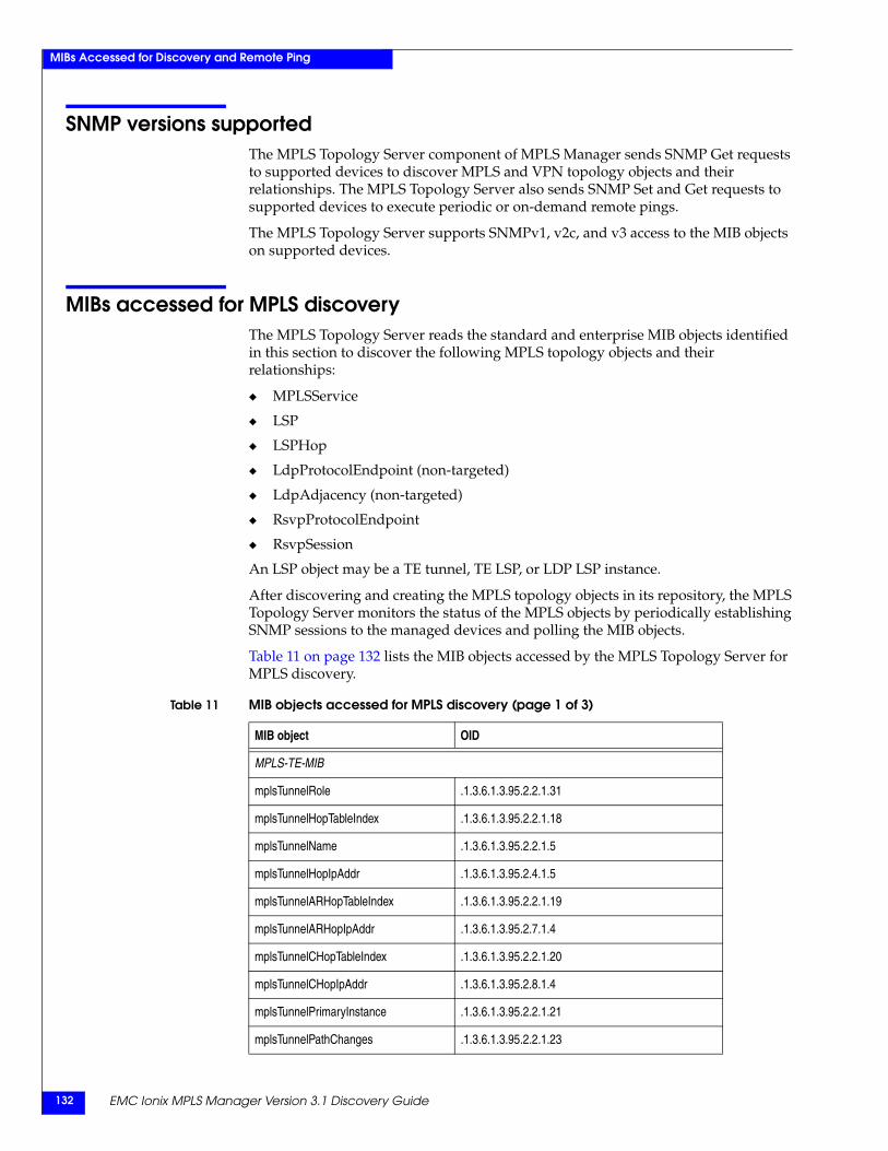
EMC Ionix MPLS Manager Version 3.1 Discovery Guide132
MIBs Accessed for Discovery and Remote Ping
SNMP versions supportedThe MPLS Topology Server component of MPLS Manager sends SNMP Get requests to supported devices to discover MPLS and VPN topology objects and their relationships. The MPLS Topology Server also sends SNMP Set and Get requests to supported devices to execute periodic or on-demand remote pings.
The MPLS Topology Server supports SNMPv1, v2c, and v3 access to the MIB objects on supported devices.
MIBs accessed for MPLS discoveryThe MPLS Topology Server reads the standard and enterprise MIB objects identified in this section to discover the following MPLS topology objects and their relationships:
◆ MPLSService
◆ LSP
◆ LSPHop
◆ LdpProtocolEndpoint (non-targeted)
◆ LdpAdjacency (non-targeted)
◆ RsvpProtocolEndpoint
◆ RsvpSession
An LSP object may be a TE tunnel, TE LSP, or LDP LSP instance.
After discovering and creating the MPLS topology objects in its repository, the MPLS Topology Server monitors the status of the MPLS objects by periodically establishing SNMP sessions to the managed devices and polling the MIB objects.
Table 11 on page 132 lists the MIB objects accessed by the MPLS Topology Server for MPLS discovery.
Table 11 MIB objects accessed for MPLS discovery (page 1 of 3)
MIB object OID
MPLS-TE-MIB
mplsTunnelRole .1.3.6.1.3.95.2.2.1.31
mplsTunnelHopTableIndex .1.3.6.1.3.95.2.2.1.18
mplsTunnelName .1.3.6.1.3.95.2.2.1.5
mplsTunnelHopIpAddr .1.3.6.1.3.95.2.4.1.5
mplsTunnelARHopTableIndex .1.3.6.1.3.95.2.2.1.19
mplsTunnelARHopIpAddr .1.3.6.1.3.95.2.7.1.4
mplsTunnelCHopTableIndex .1.3.6.1.3.95.2.2.1.20
mplsTunnelCHopIpAddr .1.3.6.1.3.95.2.8.1.4
mplsTunnelPrimaryInstance .1.3.6.1.3.95.2.2.1.21
mplsTunnelPathChanges .1.3.6.1.3.95.2.2.1.23
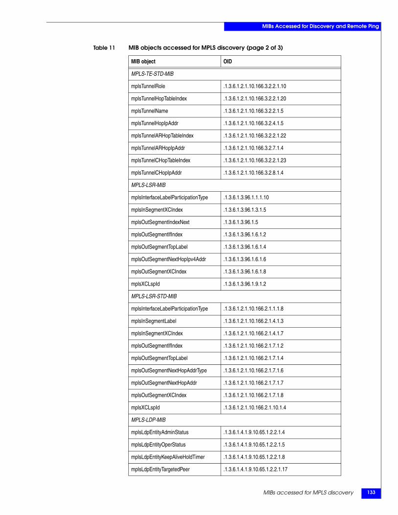
MIBs accessed for MPLS discovery 133
MIBs Accessed for Discovery and Remote Ping
MPLS-TE-STD-MIB
mplsTunnelRole .1.3.6.1.2.1.10.166.3.2.2.1.10
mplsTunnelHopTableIndex .1.3.6.1.2.1.10.166.3.2.2.1.20
mplsTunnelName .1.3.6.1.2.1.10.166.3.2.2.1.5
mplsTunnelHopIpAddr .1.3.6.1.2.1.10.166.3.2.4.1.5
mplsTunnelARHopTableIndex .1.3.6.1.2.1.10.166.3.2.2.1.22
mplsTunnelARHopIpAddr .1.3.6.1.2.1.10.166.3.2.7.1.4
mplsTunnelCHopTableIndex .1.3.6.1.2.1.10.166.3.2.2.1.23
mplsTunnelCHopIpAddr .1.3.6.1.2.1.10.166.3.2.8.1.4
MPLS-LSR-MIB
mplsInterfaceLabelParticipationType .1.3.6.1.3.96.1.1.1.10
mplsInSegmentXCIndex .1.3.6.1.3.96.1.3.1.5
mplsOutSegmentIndexNext .1.3.6.1.3.96.1.5
mplsOutSegmentIfIndex .1.3.6.1.3.96.1.6.1.2
mplsOutSegmentTopLabel .1.3.6.1.3.96.1.6.1.4
mplsOutSegmentNextHopIpv4Addr .1.3.6.1.3.96.1.6.1.6
mplsOutSegmentXCIndex .1.3.6.1.3.96.1.6.1.8
mplsXCLspId .1.3.6.1.3.96.1.9.1.2
MPLS-LSR-STD-MIB
mplsInterfaceLabelParticipationType .1.3.6.1.2.1.10.166.2.1.1.1.8
mplsInSegmentLabel .1.3.6.1.2.1.10.166.2.1.4.1.3
mplsInSegmentXCIndex .1.3.6.1.2.1.10.166.2.1.4.1.7
mplsOutSegmentIfIndex .1.3.6.1.2.1.10.166.2.1.7.1.2
mplsOutSegmentTopLabel .1.3.6.1.2.1.10.166.2.1.7.1.4
mplsOutSegmentNextHopAddrType .1.3.6.1.2.1.10.166.2.1.7.1.6
mplsOutSegmentNextHopAddr .1.3.6.1.2.1.10.166.2.1.7.1.7
mplsOutSegmentXCIndex .1.3.6.1.2.1.10.166.2.1.7.1.8
mplsXCLspId .1.3.6.1.2.1.10.166.2.1.10.1.4
MPLS-LDP-MIB
mplsLdpEntityAdminStatus .1.3.6.1.4.1.9.10.65.1.2.2.1.4
mplsLdpEntityOperStatus .1.3.6.1.4.1.9.10.65.1.2.2.1.5
mplsLdpEntityKeepAliveHoldTimer .1.3.6.1.4.1.9.10.65.1.2.2.1.8
mplsLdpEntityTargetedPeer .1.3.6.1.4.1.9.10.65.1.2.2.1.17
Table 11 MIB objects accessed for MPLS discovery (page 2 of 3)
MIB object OID
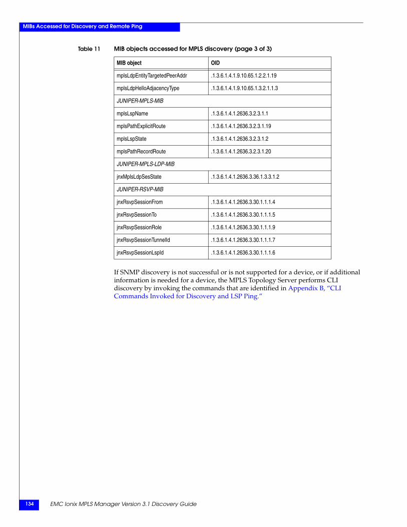
EMC Ionix MPLS Manager Version 3.1 Discovery Guide134
MIBs Accessed for Discovery and Remote Ping
If SNMP discovery is not successful or is not supported for a device, or if additional information is needed for a device, the MPLS Topology Server performs CLI discovery by invoking the commands that are identified in Appendix B, “CLI Commands Invoked for Discovery and LSP Ping.”
mplsLdpEntityTargetedPeerAddr .1.3.6.1.4.1.9.10.65.1.2.2.1.19
mplsLdpHelloAdjacencyType .1.3.6.1.4.1.9.10.65.1.3.2.1.1.3
JUNIPER-MPLS-MIB
mplsLspName .1.3.6.1.4.1.2636.3.2.3.1.1
mplsPathExplicitRoute .1.3.6.1.4.1.2636.3.2.3.1.19
mplsLspState .1.3.6.1.4.1.2636.3.2.3.1.2
mplsPathRecordRoute .1.3.6.1.4.1.2636.3.2.3.1.20
JUNIPER-MPLS-LDP-MIB
jnxMplsLdpSesState .1.3.6.1.4.1.2636.3.36.1.3.3.1.2
JUNIPER-RSVP-MIB
jnxRsvpSessionFrom .1.3.6.1.4.1.2636.3.30.1.1.1.4
jnxRsvpSessionTo .1.3.6.1.4.1.2636.3.30.1.1.1.5
jnxRsvpSessionRole .1.3.6.1.4.1.2636.3.30.1.1.1.9
jnxRsvpSessionTunnelId .1.3.6.1.4.1.2636.3.30.1.1.1.7
jnxRsvpSessionLspId .1.3.6.1.4.1.2636.3.30.1.1.1.6
Table 11 MIB objects accessed for MPLS discovery (page 3 of 3)
MIB object OID
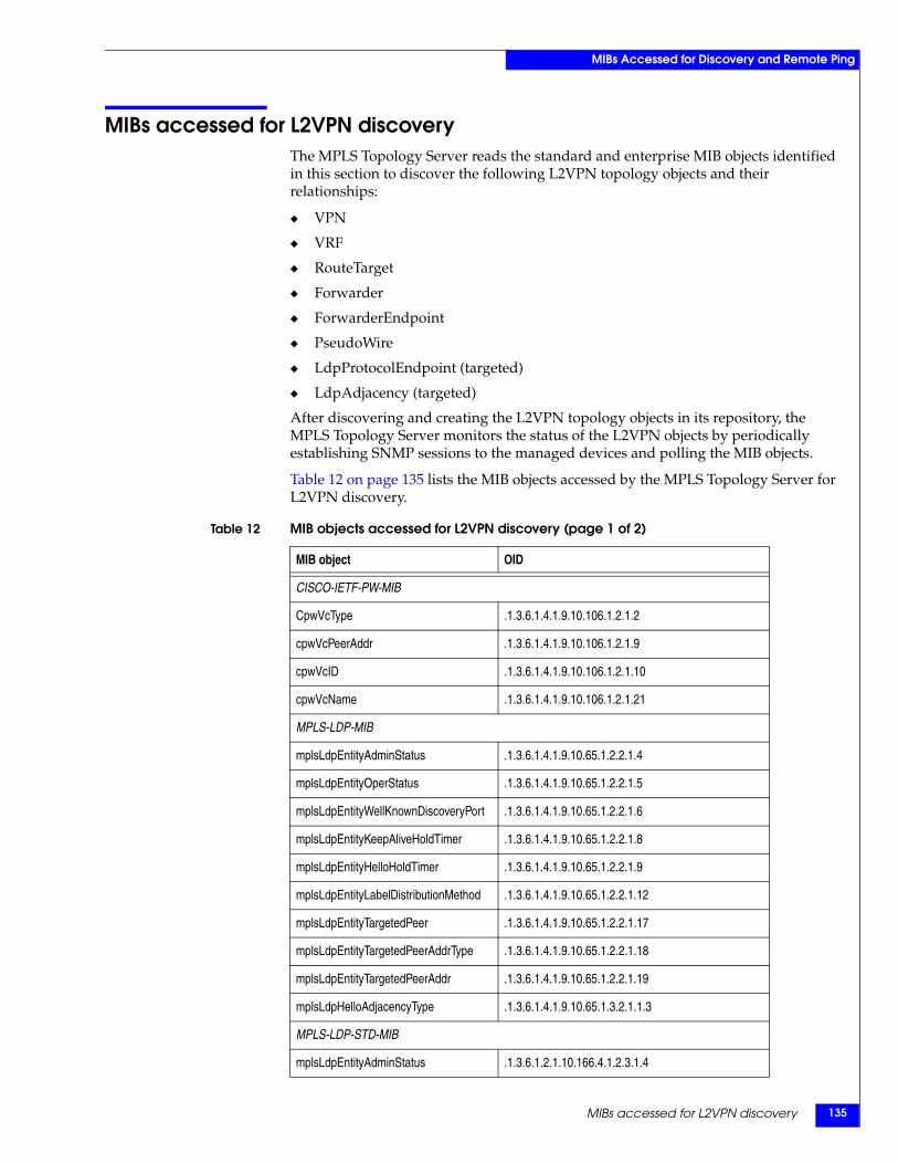
MIBs accessed for L2VPN discovery 135
MIBs Accessed for Discovery and Remote Ping
MIBs accessed for L2VPN discoveryThe MPLS Topology Server reads the standard and enterprise MIB objects identified in this section to discover the following L2VPN topology objects and their relationships:
◆ VPN
◆ VRF
◆ RouteTarget
◆ Forwarder
◆ ForwarderEndpoint
◆ PseudoWire
◆ LdpProtocolEndpoint (targeted)
◆ LdpAdjacency (targeted)
After discovering and creating the L2VPN topology objects in its repository, the MPLS Topology Server monitors the status of the L2VPN objects by periodically establishing SNMP sessions to the managed devices and polling the MIB objects.
Table 12 on page 135 lists the MIB objects accessed by the MPLS Topology Server for L2VPN discovery.
Table 12 MIB objects accessed for L2VPN discovery (page 1 of 2)
MIB object OID
CISCO-IETF-PW-MIB
CpwVcType .1.3.6.1.4.1.9.10.106.1.2.1.2
cpwVcPeerAddr .1.3.6.1.4.1.9.10.106.1.2.1.9
cpwVcID .1.3.6.1.4.1.9.10.106.1.2.1.10
cpwVcName .1.3.6.1.4.1.9.10.106.1.2.1.21
MPLS-LDP-MIB
mplsLdpEntityAdminStatus .1.3.6.1.4.1.9.10.65.1.2.2.1.4
mplsLdpEntityOperStatus .1.3.6.1.4.1.9.10.65.1.2.2.1.5
mplsLdpEntityWellKnownDiscoveryPort .1.3.6.1.4.1.9.10.65.1.2.2.1.6
mplsLdpEntityKeepAliveHoldTimer .1.3.6.1.4.1.9.10.65.1.2.2.1.8
mplsLdpEntityHelloHoldTimer .1.3.6.1.4.1.9.10.65.1.2.2.1.9
mplsLdpEntityLabelDistributionMethod .1.3.6.1.4.1.9.10.65.1.2.2.1.12
mplsLdpEntityTargetedPeer .1.3.6.1.4.1.9.10.65.1.2.2.1.17
mplsLdpEntityTargetedPeerAddrType .1.3.6.1.4.1.9.10.65.1.2.2.1.18
mplsLdpEntityTargetedPeerAddr .1.3.6.1.4.1.9.10.65.1.2.2.1.19
mplsLdpHelloAdjacencyType .1.3.6.1.4.1.9.10.65.1.3.2.1.1.3
MPLS-LDP-STD-MIB
mplsLdpEntityAdminStatus .1.3.6.1.2.1.10.166.4.1.2.3.1.4
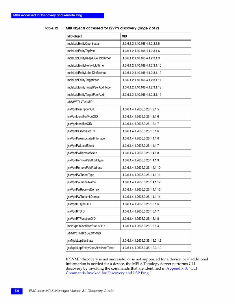
EMC Ionix MPLS Manager Version 3.1 Discovery Guide136
MIBs Accessed for Discovery and Remote Ping
If SNMP discovery is not successful or is not supported for a device, or if additional information is needed for a device, the MPLS Topology Server performs CLI discovery by invoking the commands that are identified in Appendix B, “CLI Commands Invoked for Discovery and LSP Ping.”
mplsLdpEntityOperStatus .1.3.6.1.2.1.10.166.4.1.2.3.1.5
mplsLdpEntityTcpPort .1.3.6.1.2.1.10.166.4.1.2.3.1.6
mplsLdpEntityKeepAliveHoldTimer .1.3.6.1.2.1.10.166.4.1.2.3.1.9
mplsLdpEntityHelloHoldTimer .1.3.6.1.2.1.10.166.4.1.2.3.1.10
mplsLdpEntityLabelDistMethod .1.3.6.1.2.1.10.166.4.1.2.3.1.12
mplsLdpEntityTargetPeer .1.3.6.1.2.1.10.166.4.1.2.3.1.17
mplsLdpEntityTargetPeerAddrType .1.3.6.1.2.1.10.166.4.1.2.3.1.18
mplsLdpEntityTargetPeerAddr .1.3.6.1.2.1.10.166.4.1.2.3.1.19
JUNIPER-VPN-MIB
jnxVpnDescriptionOID .1.3.6.1.4.1.2636.3.26.1.2.1.5
jnxVpnIdentifierTypeOID .1.3.6.1.4.1.2636.3.26.1.2.1.6
jnxVpnIdentifierOID .1.3.6.1.4.1.2636.3.26.1.2.1.7
jnxVpnIfAssociatedPw .1.3.6.1.4.1.2636.3.26.1.3.1.6
jnxVpnPwAssociatedInterface .1.3.6.1.4.1.2636.3.26.1.4.1.6
jnxVpnPwLocalSiteId .1.3.6.1.4.1.2636.3.26.1.4.1.7
jnxVpnPwRemoteSiteId .1.3.6.1.4.1.2636.3.26.1.4.1.8
jnxVpnRemotePeIdAddrType .1.3.6.1.4.1.2636.3.26.1.4.1.9
jnxVpnRemotePeIdAddress .1.3.6.1.4.1.2636.3.26.1.4.1.10
jnxVpnPwTunnelType .1.3.6.1.4.1.2636.3.26.1.4.1.11
jnxVpnPwTunnelName .1.3.6.1.4.1.2636.3.26.1.4.1.12
jnxVpnPwReceiveDemux .1.3.6.1.4.1.2636.3.26.1.4.1.13
jnxVpnPwTransmitDemux .1.3.6.1.4.1.2636.3.26.1.4.1.14
jnxVpnRTTypeOID .1.3.6.1.4.1.2636.3.26.1.5.1.6
jnxVpnRTOID .1.3.6.1.4.1.2636.3.26.1.5.1.7
jnxVpnRTFunctionOID .1.3.6.1.4.1.2636.3.26.1.5.1.8
mplsVpnIfConfRowStatusOID .1.3.6.1.4.1.2636.3.26.1.3.1.4
JUNIPER-MPLS-LDP-MIB
jnxMplsLdpSesState .1.3.6.1.4.1.2636.3.36.1.3.3.1.2
jnxMplsLdpEntityKeepAliveHoldTimer .1.3.6.1.4.1.2636.3.36.1.2.3.1.9
Table 12 MIB objects accessed for L2VPN discovery (page 2 of 2)
MIB object OID
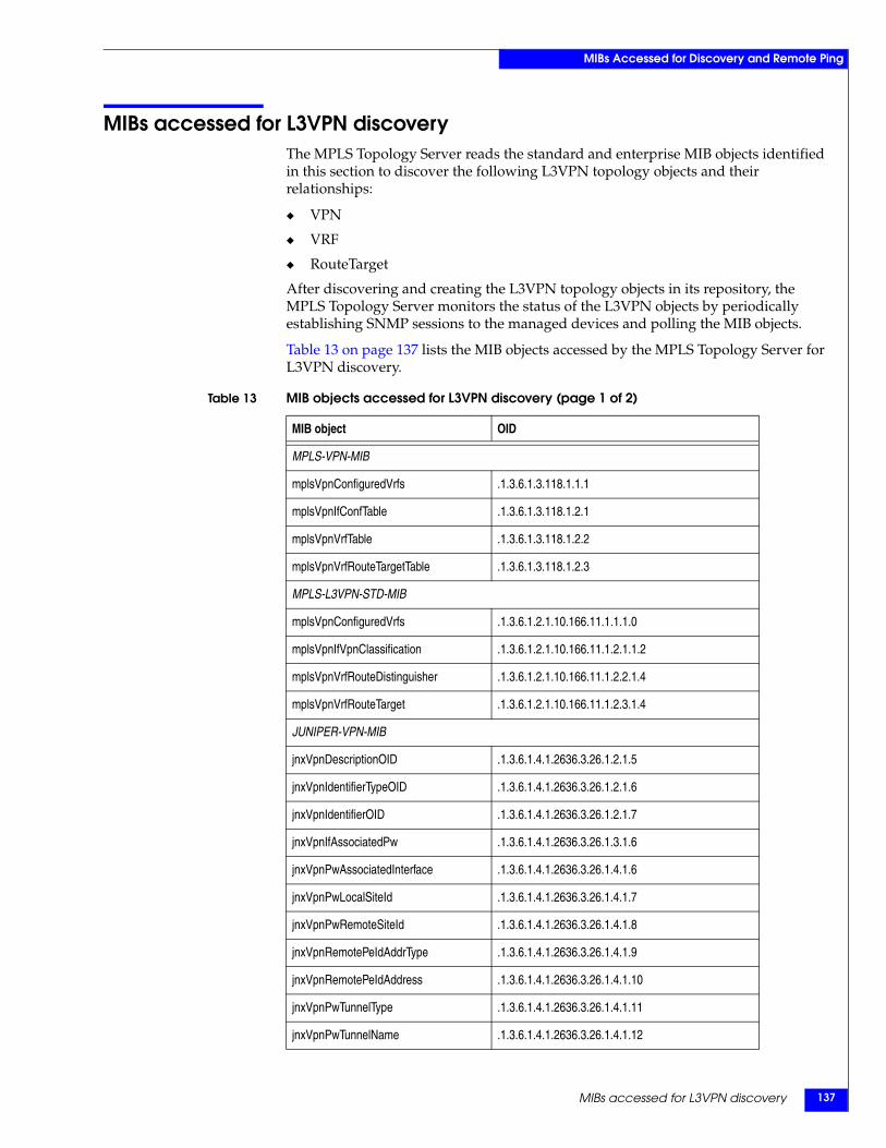
MIBs accessed for L3VPN discovery 137
MIBs Accessed for Discovery and Remote Ping
MIBs accessed for L3VPN discoveryThe MPLS Topology Server reads the standard and enterprise MIB objects identified in this section to discover the following L3VPN topology objects and their relationships:
◆ VPN
◆ VRF
◆ RouteTarget
After discovering and creating the L3VPN topology objects in its repository, the MPLS Topology Server monitors the status of the L3VPN objects by periodically establishing SNMP sessions to the managed devices and polling the MIB objects.
Table 13 on page 137 lists the MIB objects accessed by the MPLS Topology Server for L3VPN discovery.
Table 13 MIB objects accessed for L3VPN discovery (page 1 of 2)
MIB object OID
MPLS-VPN-MIB
mplsVpnConfiguredVrfs .1.3.6.1.3.118.1.1.1
mplsVpnIfConfTable .1.3.6.1.3.118.1.2.1
mplsVpnVrfTable .1.3.6.1.3.118.1.2.2
mplsVpnVrfRouteTargetTable .1.3.6.1.3.118.1.2.3
MPLS-L3VPN-STD-MIB
mplsVpnConfiguredVrfs .1.3.6.1.2.1.10.166.11.1.1.1.0
mplsVpnIfVpnClassification .1.3.6.1.2.1.10.166.11.1.2.1.1.2
mplsVpnVrfRouteDistinguisher .1.3.6.1.2.1.10.166.11.1.2.2.1.4
mplsVpnVrfRouteTarget .1.3.6.1.2.1.10.166.11.1.2.3.1.4
JUNIPER-VPN-MIB
jnxVpnDescriptionOID .1.3.6.1.4.1.2636.3.26.1.2.1.5
jnxVpnIdentifierTypeOID .1.3.6.1.4.1.2636.3.26.1.2.1.6
jnxVpnIdentifierOID .1.3.6.1.4.1.2636.3.26.1.2.1.7
jnxVpnIfAssociatedPw .1.3.6.1.4.1.2636.3.26.1.3.1.6
jnxVpnPwAssociatedInterface .1.3.6.1.4.1.2636.3.26.1.4.1.6
jnxVpnPwLocalSiteId .1.3.6.1.4.1.2636.3.26.1.4.1.7
jnxVpnPwRemoteSiteId .1.3.6.1.4.1.2636.3.26.1.4.1.8
jnxVpnRemotePeIdAddrType .1.3.6.1.4.1.2636.3.26.1.4.1.9
jnxVpnRemotePeIdAddress .1.3.6.1.4.1.2636.3.26.1.4.1.10
jnxVpnPwTunnelType .1.3.6.1.4.1.2636.3.26.1.4.1.11
jnxVpnPwTunnelName .1.3.6.1.4.1.2636.3.26.1.4.1.12
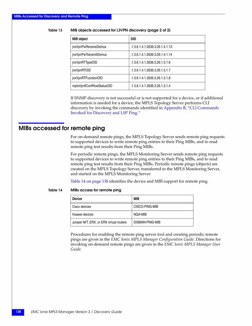
EMC Ionix MPLS Manager Version 3.1 Discovery Guide138
MIBs Accessed for Discovery and Remote Ping
If SNMP discovery is not successful or is not supported for a device, or if additional information is needed for a device, the MPLS Topology Server performs CLI discovery by invoking the commands identified in Appendix B, “CLI Commands Invoked for Discovery and LSP Ping.”
MIBs accessed for remote pingFor on-demand remote pings, the MPLS Topology Server sends remote ping requests to supported devices to write remote ping entries to their Ping MIBs, and to read remote ping test results from their Ping MIBs.
For periodic remote pings, the MPLS Monitoring Server sends remote ping requests to supported devices to write remote ping entries to their Ping MIBs, and to read remote ping test results from their Ping MIBs. Periodic remote pings (objects) are created on the MPLS Topology Server, transferred to the MPLS Monitoring Server, and started on the MPLS Monitoring Server.
Table 14 on page 138 identifies the device and MIB support for remote ping.
Procedures for enabling the remote ping server tool and creating periodic remote pings are given in the EMC Ionix MPLS Manager Configuration Guide. Directions for invoking on-demand remote pings are given in the EMC Ionix MPLS Manager User Guide.
jnxVpnPwReceiveDemux .1.3.6.1.4.1.2636.3.26.1.4.1.13
jnxVpnPwTransmitDemux .1.3.6.1.4.1.2636.3.26.1.4.1.14
jnxVpnRTTypeOID .1.3.6.1.4.1.2636.3.26.1.5.1.6
jnxVpnRTOID .1.3.6.1.4.1.2636.3.26.1.5.1.7
jnxVpnRTFunctionOID .1.3.6.1.4.1.2636.3.26.1.5.1.8
mplsVpnIfConfRowStatusOID .1.3.6.1.4.1.2636.3.26.1.3.1.4
Table 13 MIB objects accessed for L3VPN discovery (page 2 of 2)
MIB object OID
Table 14 MIBs access for remote ping
Device MIB
Cisco devices CISCO-PING-MIB
Huawei devices NQA-MIB
Juniper M/T, ERX, or ERX virtual routers DISMAN-PING-MIB

CLI Commands Invoked for Discovery and LSP Ping 139
B
This appendix identifies the CLI commands invoked by MPLS Manager to discover MPLS and VPN topology and to perform LSP pings. It consists of the following sections:
◆ CLI commands overview............................................................................................ 140◆ CLI commands invoked on Cisco devices................................................................ 140◆ CLI commands invoked on Huawei devices ........................................................... 142◆ CLI commands invoked on Juniper M/T devices................................................... 143◆ CLI commands invoked on Juniper ERX devices ................................................... 144◆ CLI commands invoked for LSP ping....................................................................... 146
CLI CommandsInvoked for Discovery
and LSP Ping
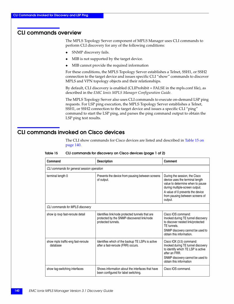
EMC Ionix MPLS Manager Version 3.1 Discovery Guide140
CLI Commands Invoked for Discovery and LSP Ping
CLI commands overviewThe MPLS Topology Server component of MPLS Manager uses CLI commands to perform CLI discovery for any of the following conditions:
◆ SNMP discovery fails.
◆ MIB is not supported by the target device.
◆ MIB cannot provide the required information
For these conditions, the MPLS Topology Server establishes a Telnet, SSH1, or SSH2 connection to the target device and issues specific CLI “show” commands to discover MPLS and VPN topology objects and their relationships.
By default, CLI discovery is enabled (CLIProhibit = FALSE in the mpls.conf file), as described in the EMC Ionix MPLS Manager Configuration Guide.
The MPLS Topology Server also uses CLI commands to execute on-demand LSP ping requests. For LSP ping execution, the MPLS Topology Server establishes a Telnet, SSH1, or SSH2 connection to the target device and issues a specific CLI “ping” command to start the LSP ping, and parses the ping command output to obtain the LSP ping test results.
CLI commands invoked on Cisco devicesThe CLI show commands for Cisco devices are listed and described in Table 15 on page 140.
Table 15 CLI commands for discovery on Cisco devices (page 1 of 2)
Command Description Comment
CLI commands for general session operation
terminal length 0 Prevents the device from pausing between screens of output.
During the session, the Cisco device uses the terminal length value to determine when to pause during multiple-screen output.A value of 0 prevents the device from pausing between screens of output.
CLI commands for MPLS discovery
show ip rsvp fast-reroute detail Identifies link/node protected tunnels that are protected by the SNMP-discovered link/node protected tunnels.
Cisco IOS command:Invoked during TE tunnel discovery to discover nested link/protected TE tunnels.SNMP discovery cannot be used to obtain this information.
show mpls traffic-eng fast-reroute database
Identifies which of the backup TE LSPs is active after a fast-reroute (FRR) occurs.
Cisco IOX (3.5) command:Invoked during TE tunnel discovery to identify which TE LSP is active after an FRR.SNMP discovery cannot be used to obtain this information
show tag-switching interfaces Shows information about the interfaces that have been configured for label switching.
Cisco IOS command.
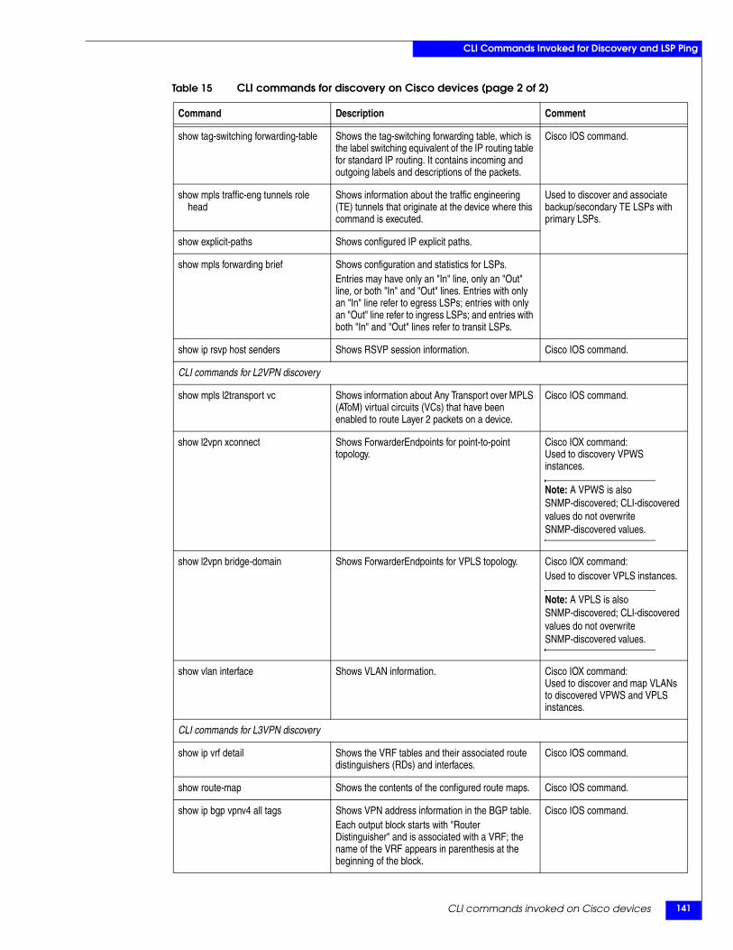
CLI commands invoked on Cisco devices 141
CLI Commands Invoked for Discovery and LSP Ping
show tag-switching forwarding-table Shows the tag-switching forwarding table, which is the label switching equivalent of the IP routing table for standard IP routing. It contains incoming and outgoing labels and descriptions of the packets.
Cisco IOS command.
show mpls traffic-eng tunnels role head
Shows information about the traffic engineering (TE) tunnels that originate at the device where this command is executed.
Used to discover and associate backup/secondary TE LSPs with primary LSPs.
show explicit-paths Shows configured IP explicit paths.
show mpls forwarding brief Shows configuration and statistics for LSPs.Entries may have only an "In" line, only an "Out" line, or both "In" and "Out" lines. Entries with only an "In" line refer to egress LSPs; entries with only an "Out" line refer to ingress LSPs; and entries with both "In" and "Out" lines refer to transit LSPs.
show ip rsvp host senders Shows RSVP session information. Cisco IOS command.
CLI commands for L2VPN discovery
show mpls l2transport vc Shows information about Any Transport over MPLS (AToM) virtual circuits (VCs) that have been enabled to route Layer 2 packets on a device.
Cisco IOS command.
show l2vpn xconnect Shows ForwarderEndpoints for point-to-point topology.
Cisco IOX command:Used to discovery VPWS instances.
Note: A VPWS is also SNMP-discovered; CLI-discovered values do not overwrite SNMP-discovered values.
show l2vpn bridge-domain Shows ForwarderEndpoints for VPLS topology. Cisco IOX command:Used to discover VPLS instances.
Note: A VPLS is also SNMP-discovered; CLI-discovered values do not overwrite SNMP-discovered values.
show vlan interface Shows VLAN information. Cisco IOX command:Used to discover and map VLANs to discovered VPWS and VPLS instances.
CLI commands for L3VPN discovery
show ip vrf detail Shows the VRF tables and their associated route distinguishers (RDs) and interfaces.
Cisco IOS command.
show route-map Shows the contents of the configured route maps. Cisco IOS command.
show ip bgp vpnv4 all tags Shows VPN address information in the BGP table.Each output block starts with "Router Distinguisher" and is associated with a VRF; the name of the VRF appears in parenthesis at the beginning of the block.
Cisco IOS command.
Table 15 CLI commands for discovery on Cisco devices (page 2 of 2)
Command Description Comment
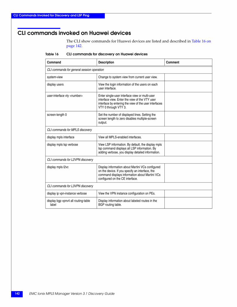
EMC Ionix MPLS Manager Version 3.1 Discovery Guide142
CLI Commands Invoked for Discovery and LSP Ping
CLI commands invoked on Huawei devicesThe CLI show commands for Huawei devices are listed and described in Table 16 on page 142.
Table 16 CLI commands for discovery on Huawei devices
Command Description Comment
CLI commands for general session operation
system-view Change to system view from current user view.
display users View the login information of the users on each user interface.
user-interface vty <number> Enter single-user interface view or multi-user interface view. Enter the view of the VTY user interface by entering the view of the user interfaces VTY 0 through VTY 3.
screen-length 0 Set the number of displayed lines. Setting the screen length to zero disables multiple-screen output.
CLI commands for MPLS discovery
display mpls interface View all MPLS-enabled interfaces.
display mpls lsp verbose View LSP information. By default, the display mpls lsp command displays all LSP information. By adding verbose, you display detailed information.
CLI commands for L2VPN discovery
display mpls l2vc Display information about Martini VCs configured on the device. If you specify an interface, the command displays information about Martini VCs configured on the CE interface.
CLI commands for L3VPN discovery
display ip vpn-instance verbose View the VPN instance configuration on PEs.
display bgp vpnv4 all routing-table label
Display information about labeled routes in the BGP routing table.
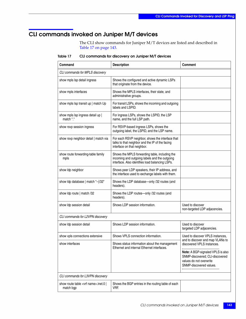
CLI commands invoked on Juniper M/T devices 143
CLI Commands Invoked for Discovery and LSP Ping
CLI commands invoked on Juniper M/T devicesThe CLI show commands for Juniper M/T devices are listed and described in Table 17 on page 143.
Table 17 CLI commands for discovery on Juniper M/T devices
Command Description Comment
CLI commands for MPLS discovery
show mpls lsp detail ingress Shows the configured and active dynamic LSPs that originate from the device.
show mpls interfaces Shows the MPLS interfaces, their state, and administrative groups.
show mpls lsp transit up | match Up For transit LSPs, shows the incoming and outgoing labels and LSPID.
show mpls lsp ingress detail up | match "."
For ingress LSPs, shows the LSPID, the LSP name, and the full LSP path.
show rsvp session ingress For RSVP-based ingress LSPs, shows the outgoing label, the LSPID, and the LSP name.
show rsvp neighbor detail | match via For each RSVP neighbor, shows the interface that talks to that neighbor and the IP of the facing interface on that neighbor.
show route forwarding-table family mpls
Shows the MPLS forwarding table, including the incoming and outgoing labels and the outgoing interface. Also identifies load balancing LSPs.
show ldp neighbor Shows peer LDP speakers, their IP address, and the interface used to exchange labels with them.
show ldp database | match "--|/32" Shows the LDP database—only /32 routes (and headers).
show ldp route | match /32 Shows the LDP routes—only /32 routes (and headers).
show ldp session detail Shows LDP session information. Used to discovernon-targeted LDP adjacencies.
CLI commands for L2VPN discovery
show ldp session detail Shows LDP session information. Used to discovertargeted LDP adjacencies.
show vpls connections extensive Shows VPLS connection information. Used to discover VPLS instances, and to discover and map VLANs to discovered VPLS instances.
Note: A BGP-signaled VPLS is also SNMP-discovered; CLI-discovered values do not overwrite SNMP-discovered values.
show interfaces Shows status information about the management Ethernet and internal Ethernet interfaces.
CLI commands for L3VPN discovery
show route table <vrf name>.inet.0 | match bgp
Shows the BGP entries in the routing table of each VRF.
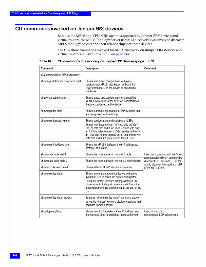
EMC Ionix MPLS Manager Version 3.1 Discovery Guide144
CLI Commands Invoked for Discovery and LSP Ping
CLI commands invoked on Juniper ERX devicesBecause the MPLS and VPN MIBs are not supported by Juniper ERX devices and virtual routers, the MPLS Topology Server uses CLI discovery exclusively to discover MPLS topology objects and their relationships for these devices.
The CLI show commands invoked for MPLS discovery on Juniper ERX devices and virtual routers are listed in Table 18 on page 144.
Table 18 CLI commands for discovery on Juniper ERX devices (page 1 of 2)
Command Description Comment
CLI commands for MPLS discovery
show mpls l2transport interface brief Shows status and configuration for Layer 2 services over MPLS, also known as Martini or Layer 2 transport, on the device or on specific interfaces.
show vlan subinterface Shows status and configuration for a specified VLAN subinterface, or for all VLAN subinterfaces that are configured on the device.
show mpls for brief Shows summary information for MPLS labels that are being used for forwarding.
show mpls forwarding brief Shows configuration and statistics for LSPs.Entries may have only an "In" line, only an "Out" line, or both "In" and "Out" lines. Entries with only an "In" line refer to egress LSPs; entries with only an "Out" line refer to ingress LSPs; and entries with both "In" and "Out" lines refer to transit LSPs.
show mpls interfaces brief Shows the MPLS interfaces, their IP addresses, protocol, and status.
show route table inet.3 Shows the route entries in the inet.3 table. Used in conjunction with the “show mpls forwarding brief” command to discover LDP LSPs and TE LSPs, and to discover the stacking of LDP LSPs on TE LSPs.
show route table mpls.0 Shows the route entries in the mpls.0 routing table.
show rsvp session detail Shows detailed RSVP session information.
show mpls lsp detail Shows information about configured and active dynamic LSPs in which the device participates. Using the “detail” keyword displays detailed LSP information, including all current state information and all parameters and counters that are part of the LSP.
show mpls lsp detail ingress Same as “show mpls lsp detail” command above.Using the “ingress” keyword displays sessions that originate from the device.
show ldp neighbor Shows peer LDP speakers, their IP address, and the interface used to exchange labels with them.
Used to discovernon-targeted LDP adjacencies.
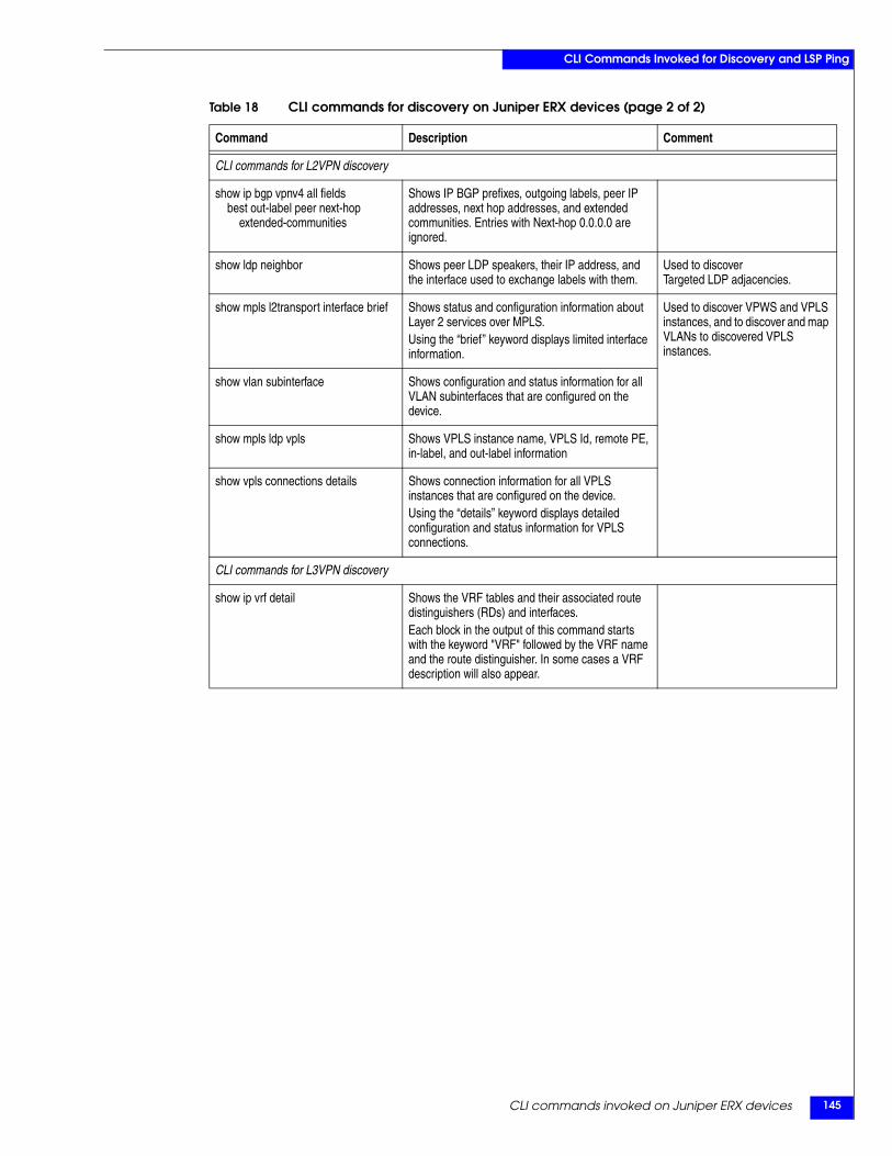
CLI commands invoked on Juniper ERX devices 145
CLI Commands Invoked for Discovery and LSP Ping
CLI commands for L2VPN discovery
show ip bgp vpnv4 all fields best out-label peer next-hop
extended-communities
Shows IP BGP prefixes, outgoing labels, peer IP addresses, next hop addresses, and extended communities. Entries with Next-hop 0.0.0.0 are ignored.
show ldp neighbor Shows peer LDP speakers, their IP address, and the interface used to exchange labels with them.
Used to discoverTargeted LDP adjacencies.
show mpls l2transport interface brief Shows status and configuration information about Layer 2 services over MPLS.Using the “brief” keyword displays limited interface information.
Used to discover VPWS and VPLS instances, and to discover and map VLANs to discovered VPLS instances.
show vlan subinterface Shows configuration and status information for all VLAN subinterfaces that are configured on the device.
show mpls ldp vpls Shows VPLS instance name, VPLS Id, remote PE, in-label, and out-label information
show vpls connections details Shows connection information for all VPLS instances that are configured on the device.Using the “details” keyword displays detailed configuration and status information for VPLS connections.
CLI commands for L3VPN discovery
show ip vrf detail Shows the VRF tables and their associated route distinguishers (RDs) and interfaces.Each block in the output of this command starts with the keyword "VRF" followed by the VRF name and the route distinguisher. In some cases a VRF description will also appear.
Table 18 CLI commands for discovery on Juniper ERX devices (page 2 of 2)
Command Description Comment
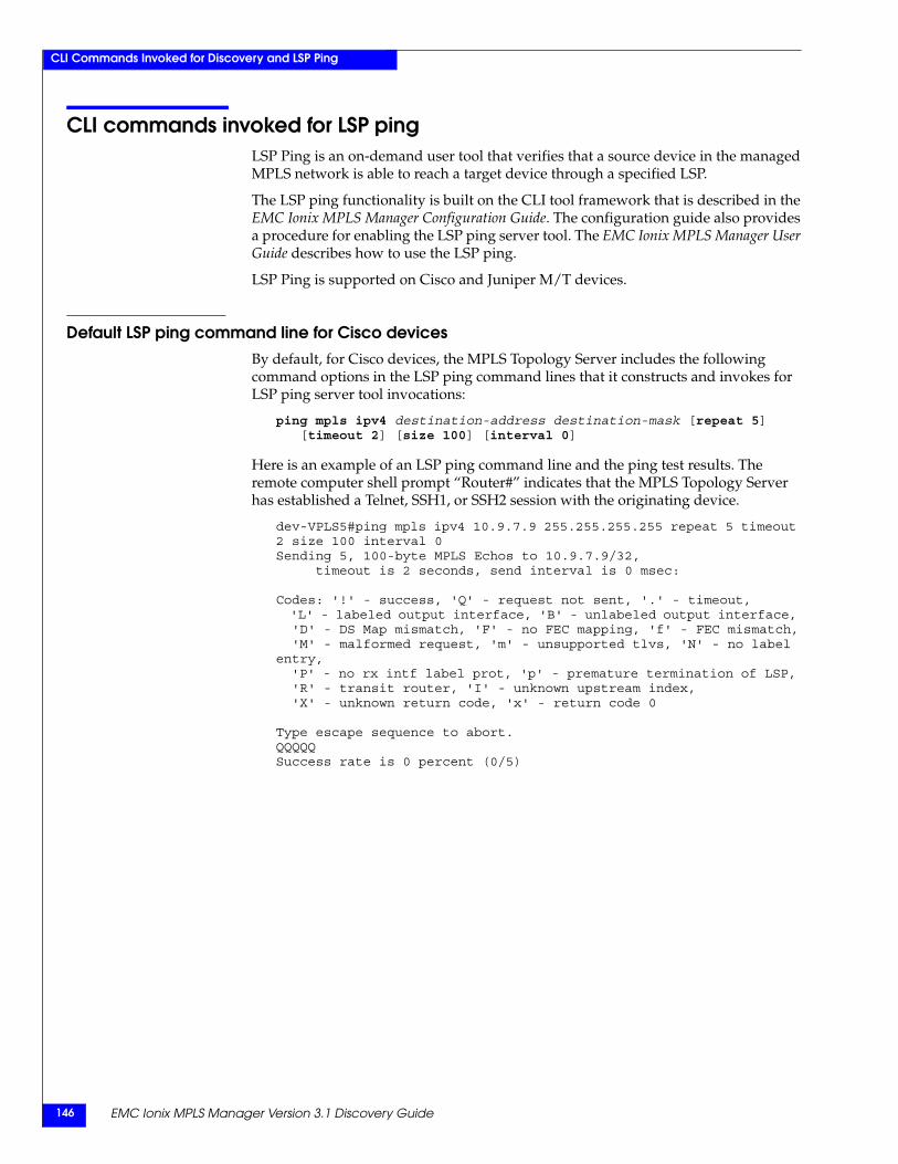
EMC Ionix MPLS Manager Version 3.1 Discovery Guide146
CLI Commands Invoked for Discovery and LSP Ping
CLI commands invoked for LSP pingLSP Ping is an on-demand user tool that verifies that a source device in the managed MPLS network is able to reach a target device through a specified LSP.
The LSP ping functionality is built on the CLI tool framework that is described in the EMC Ionix MPLS Manager Configuration Guide. The configuration guide also provides a procedure for enabling the LSP ping server tool. The EMC Ionix MPLS Manager User Guide describes how to use the LSP ping.
LSP Ping is supported on Cisco and Juniper M/T devices.
Default LSP ping command line for Cisco devicesBy default, for Cisco devices, the MPLS Topology Server includes the following command options in the LSP ping command lines that it constructs and invokes for LSP ping server tool invocations:
ping mpls ipv4 destination-address destination-mask [repeat 5] [timeout 2] [size 100] [interval 0]
Here is an example of an LSP ping command line and the ping test results. The remote computer shell prompt “Router#” indicates that the MPLS Topology Server has established a Telnet, SSH1, or SSH2 session with the originating device.
dev-VPLS5#ping mpls ipv4 10.9.7.9 255.255.255.255 repeat 5 timeout 2 size 100 interval 0Sending 5, 100-byte MPLS Echos to 10.9.7.9/32, timeout is 2 seconds, send interval is 0 msec:
Codes: '!' - success, 'Q' - request not sent, '.' - timeout, 'L' - labeled output interface, 'B' - unlabeled output interface, 'D' - DS Map mismatch, 'F' - no FEC mapping, 'f' - FEC mismatch, 'M' - malformed request, 'm' - unsupported tlvs, 'N' - no label entry, 'P' - no rx intf label prot, 'p' - premature termination of LSP, 'R' - transit router, 'I' - unknown upstream index, 'X' - unknown return code, 'x' - return code 0
Type escape sequence to abort.QQQQQSuccess rate is 0 percent (0/5)

CLI commands invoked for LSP ping 147
CLI Commands Invoked for Discovery and LSP Ping
Default LSP ping command line for Juniper M/T devicesBy default, for Juniper M/T devices, the MPLS Topology Server includes the following command options in the LSP ping command lines that it constructs and invokes for LSP ping server tool invocations:
ping mpls ldp destination-address [count 5]
Here is an example of an LSP ping command line and the ping test results. The remote computer shell prompt “juniper@dev-MPLSp8>” indicates that the MPLS Topology Server has established a Telnet, SSH1, or SSH2 session with the originating device.
juniper@dev-MPLSp8> ping mpls ldp 192.168.17.1 count 5 !!!!!--- lsping statistics ---5 packets transmitted, 5 packets received, 0% packet loss
LSP ping customizationIn you so choose, you can change the global values that are specified for the options in the default LSP ping command line. The procedure for doing so is given in the EMC Ionix MPLS Manager Configuration Guide.

EMC Ionix MPLS Manager Version 3.1 Discovery Guide148
CLI Commands Invoked for Discovery and LSP Ping

EMC Ionix MPLS Manager Version 3.1 Discovery Guide 149
Symbols.import files 51, 109
AAdapters
EMC Ionix Adapter for Alcatel-Lucent 5620 SAM EMS 39
Availability ManagerTopology export 26, 49
BBGP-signaled L2VPN 78, 87BGP-signaled L2VPNs 89
CCE device 66Class
Forwarder 92ForwarderEndpoint 88LdpAdjacency 74, 92LdpProtocolEndpoint 70, 89LSP 71LSPHop 74LspTableManager 67MPLSService 66PseudoWire 90RouteTarget 89, 102RsvpProtocolEndpoint 70RsvpSession 75VLAN 93VPN 93, 103VRF 89, 102
CLILog files 31
CLI commands 139CLI support 20
DDevice
Definition of 16Device support 20
Cisco 20Huawei 20Juniper 20
DevicesCE 66Multi-VRF CE 66P 66PE 66
Discovery.import files 51, 109Definition of 16Discover Pending command 130Discovery errors 119Initiating 107Invoking 127IP Availability Manager 25MPLS objects 26Overview 15, 24Pending Devices list 129Pending Elements list 52, 53, 125Phases of 48
Phase 1 49Phase 2 50Phase 3 53
Preparing for 107Process 45, 55, 77, 97Progress window 119, 121Scheduled discovery interval 129Triggers 31VPN objects 28, 30
Discovery errors 119Discovery process 45, 55, 77, 97Discovery Progress window 119, 121, 125Discovery protocols
SNMP 20Telnet, SSH1, or SSH2 CLI 20
dmctl 130Domain Manager
Definition of 16Domain Manager Administration Console 121
Discover Pending command 130Discovery Progress window 119, 121
Index
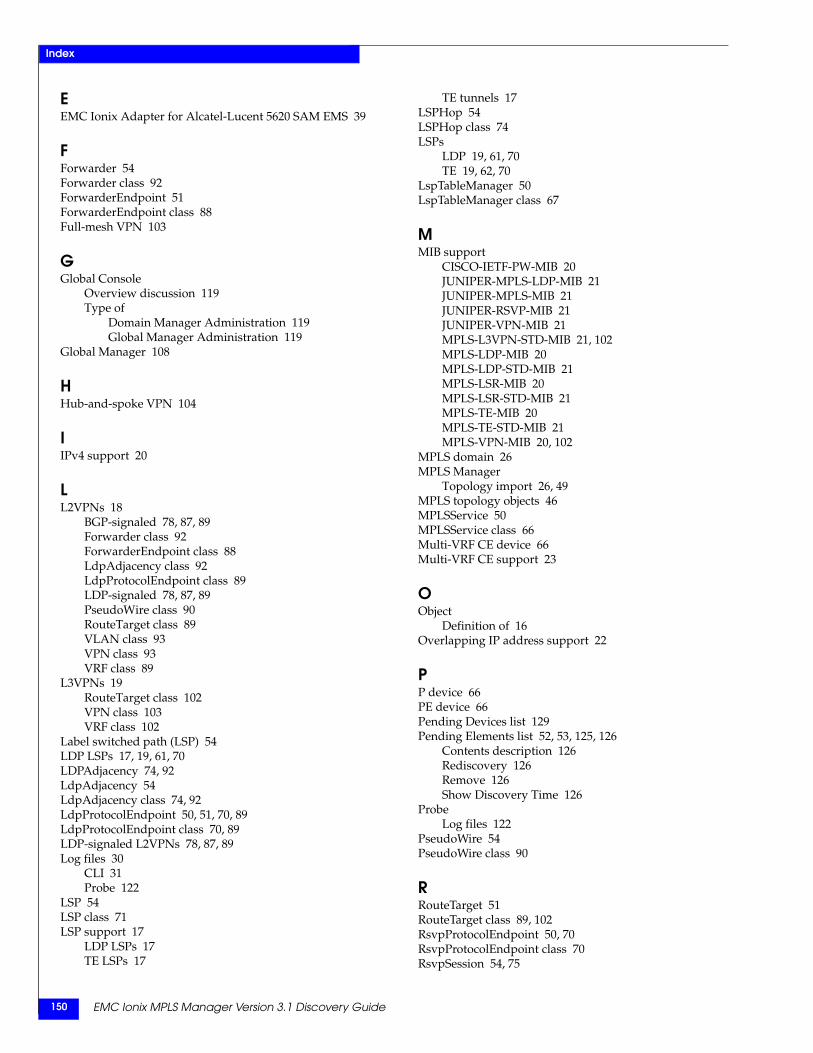
EMC Ionix MPLS Manager Version 3.1 Discovery Guide150
Index
EEMC Ionix Adapter for Alcatel-Lucent 5620 SAM EMS 39
FForwarder 54Forwarder class 92ForwarderEndpoint 51ForwarderEndpoint class 88Full-mesh VPN 103
GGlobal Console
Overview discussion 119Type of
Domain Manager Administration 119Global Manager Administration 119
Global Manager 108
HHub-and-spoke VPN 104
IIPv4 support 20
LL2VPNs 18
BGP-signaled 78, 87, 89Forwarder class 92ForwarderEndpoint class 88LdpAdjacency class 92LdpProtocolEndpoint class 89LDP-signaled 78, 87, 89PseudoWire class 90RouteTarget class 89VLAN class 93VPN class 93VRF class 89
L3VPNs 19RouteTarget class 102VPN class 103VRF class 102
Label switched path (LSP) 54LDP LSPs 17, 19, 61, 70LDPAdjacency 74, 92LdpAdjacency 54LdpAdjacency class 74, 92LdpProtocolEndpoint 50, 51, 70, 89LdpProtocolEndpoint class 70, 89LDP-signaled L2VPNs 78, 87, 89Log files 30
CLI 31Probe 122
LSP 54LSP class 71LSP support 17
LDP LSPs 17TE LSPs 17
TE tunnels 17LSPHop 54LSPHop class 74LSPs
LDP 19, 61, 70TE 19, 62, 70
LspTableManager 50LspTableManager class 67
MMIB support
CISCO-IETF-PW-MIB 20JUNIPER-MPLS-LDP-MIB 21JUNIPER-MPLS-MIB 21JUNIPER-RSVP-MIB 21JUNIPER-VPN-MIB 21MPLS-L3VPN-STD-MIB 21, 102MPLS-LDP-MIB 20MPLS-LDP-STD-MIB 21MPLS-LSR-MIB 20MPLS-LSR-STD-MIB 21MPLS-TE-MIB 20MPLS-TE-STD-MIB 21MPLS-VPN-MIB 20, 102
MPLS domain 26MPLS Manager
Topology import 26, 49MPLS topology objects 46MPLSService 50MPLSService class 66Multi-VRF CE device 66Multi-VRF CE support 23
OObject
Definition of 16Overlapping IP address support 22
PP device 66PE device 66Pending Devices list 129Pending Elements list 52, 53, 125, 126
Contents description 126Rediscovery 126Remove 126Show Discovery Time 126
ProbeLog files 122
PseudoWire 54PseudoWire class 90
RRouteTarget 51RouteTarget class 89, 102RsvpProtocolEndpoint 50, 70RsvpProtocolEndpoint class 70RsvpSession 54, 75
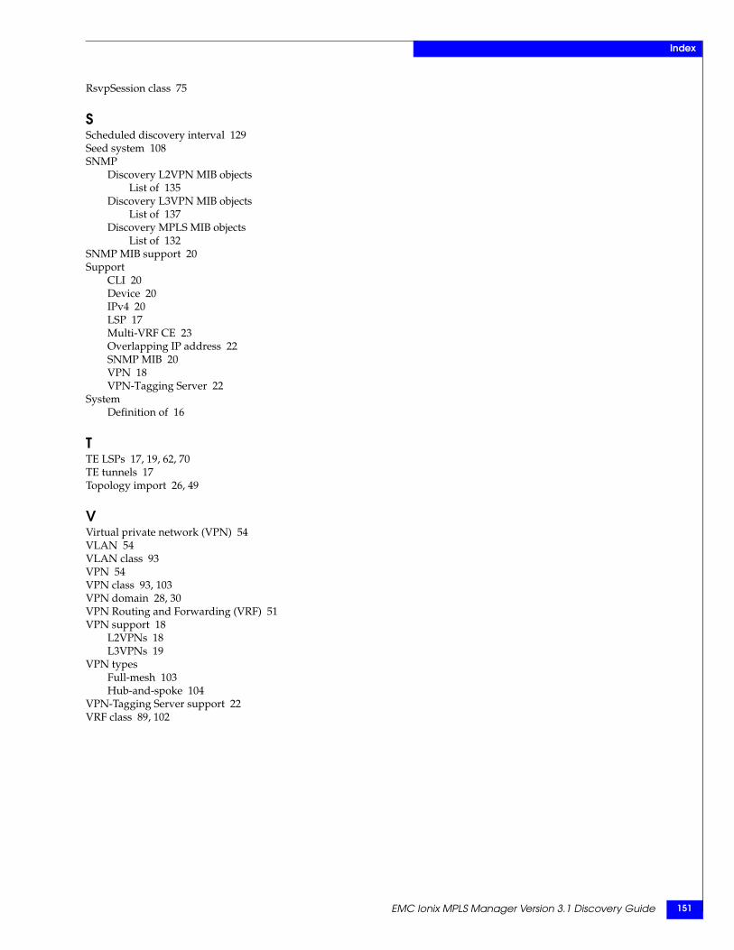
EMC Ionix MPLS Manager Version 3.1 Discovery Guide 151
Index
RsvpSession class 75
SScheduled discovery interval 129Seed system 108SNMP
Discovery L2VPN MIB objectsList of 135
Discovery L3VPN MIB objectsList of 137
Discovery MPLS MIB objectsList of 132
SNMP MIB support 20Support
CLI 20Device 20IPv4 20LSP 17Multi-VRF CE 23Overlapping IP address 22SNMP MIB 20VPN 18VPN-Tagging Server 22
SystemDefinition of 16
TTE LSPs 17, 19, 62, 70TE tunnels 17Topology import 26, 49
VVirtual private network (VPN) 54VLAN 54VLAN class 93VPN 54VPN class 93, 103VPN domain 28, 30VPN Routing and Forwarding (VRF) 51VPN support 18
L2VPNs 18L3VPNs 19
VPN typesFull-mesh 103Hub-and-spoke 104
VPN-Tagging Server support 22VRF class 89, 102

EMC Ionix MPLS Manager Version 3.1 Discovery Guide152
Index