Embed Size (px)
Citation preview
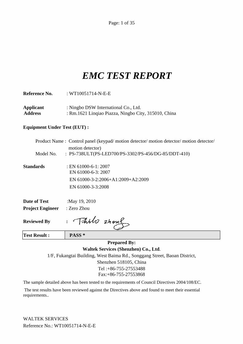
Page: 1 of 35
EMC TEST REPORT
WALTEK SERVICES Reference No.: WT10051714-N-E-E
Reference No. : WT10051714-N-E-E Applicant : Ningbo DSW International Co., Ltd. Address : Rm.1621 Linqiao Piazza, Ningbo City, 315010, China Equipment Under Test (EUT) :
Product Name : Control panel (keypad/ motion detector/ motion detector/ motion detector/ motion detector)
Model No. : PS-738ULT(PS-LED700/PS-3302/PS-456/DG-85/DDT-410)
Standards : EN 61000-6-1: 2007 EN 61000-6-3: 2007 EN 61000-3-2:2006+A1:2009+A2:2009 EN 61000-3-3:2008
Date of Test :May 19, 2010 Project Engineer : Zero Zhou Reviewed By : Test Result : PASS *
Prepared By: Waltek Services (Shenzhen) Co., Ltd.
1/F, Fukangtai Building, West Baima Rd., Songgang Street, Baoan District, Shenzhen 518105, China Tel :+86-755-27553488 Fax:+86-755-27553868
The sample detailed above has been tested to the requirements of Council Directives 2004/108/EC.
The test results have been reviewed against the Directives above and found to meet their essential requirements..
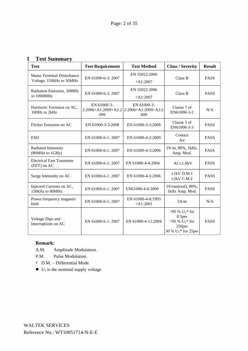
Page: 2 of 35
WALTEK SERVICES Reference No.: WT10051714-N-E-E
1 Test Summary Test Test Requirement Test Method Class / Severity Result
Mains Terminal Disturbance Voltage, 150kHz to 30MHz EN 61000-6-3: 2007
EN 55022:2006
+A1:2007 Class B PASS
Radiation Emission, 30MHz to 1000MHz EN 61000-6-3: 2007
EN 55022:2006
+A1:2007 Class B PASS
Harmonic Emission on AC, 100Hz to 2kHz
EN 61000-3-2:2006+A1:2009+A2:2
009
EN 61000-3-2:2006+A1:2009+A2:2
009
Clause 7 of EN61000-3-2 N/A
Flicker Emission on AC EN 61000-3-3:2008 EN 61000-3-3:2008 Clause 5 of EN61000-3-3 PASS
ESD EN 61000-6-1: 2007 EN 61000-4-2:2009 Contact Air PASS
Radiated Immunity (80MHz to 1GHz) EN 61000-6-1: 2007 EN 61000-4-3:2006 3V/m, 80%, 1kHz,
Amp. Mod. PASS
Electrical Fast Transients (EFT) on AC EN 61000-6-1: 2007 EN 61000-4-4:2004 AC±1.0kV PASS
Surge Immunity on AC EN 61000-6-1: 2007 EN 61000-4-5:2006 ±1kV D.M.† ±2kV C.M.‡ PASS
Injected Currents on AC, 150kHz to 80MHz EN 61000-6-1: 2007 EN61000-4-6:2009 3Vrms(emf), 80%,
1kHz Amp. Mod. PASS
Power-frequency magnetic field EN 61000-6-1: 2007 EN 61000-4-8:1993
+A1:2001 3A/m N/A
Voltage Dips and Interruptions on AC EN 61000-6-1: 2007 EN 61000-4-11:2004
>95 % UT* for 0.5per
>95 % UT* for 250per
30 % UT* for 25per
PASS
Remark: A.M. Amplitude Modulation. P.M. Pulse Modulation. † D.M. – Differential Mode
UT is the nominal supply voltage
Page:3 of 35
WALTEK SERVICES Reference No.: WT10051714-N-E-E
2 Contents Page 1 TEST SUMMARY ................................................................................................................................................... 2
2 CONTENTS .............................................................................................................................................................. 3
3 GENERAL INFORMATION ................................................................................................................................. 5
3.1 CLIENT INFORMATION ........................................................................................................................................... 5 3.2 DETAILS OF E.U.T. ................................................................................................................................................ 5 3.3 DESCRIPTION OF SUPPORT UNITS .......................................................................................................................... 5 3.4 STANDARDS APPLICABLE FOR TESTING ................................................................................................................ 5 3.5 TEST FACILITY ...................................................................................................................................................... 6 3.6 TEST LOCATION .................................................................................................................................................... 6
4 EQUIPMENT USED DURING TEST ................................................................................................................... 7
5 CONDUCTED EMISSION TEST RESULTS ....................................................................................................... 9
5.1 MAINS TERMINALS DISTURBANCE VOLTAGE, 150KHZ TO 30MHZ ....................................................................... 9 5.1.1 E.U.T. Operation ........................................................................................................................................ 9 5.1.2 Conducted Test Setup ................................................................................................................................. 9 5.1.3 Measurement Data .................................................................................................................................... 10 5.1.4 Conducted Emissions Test Data ............................................................................................................... 11 5.1.5 Photograph – Mains Terminal Disturbance Voltage on AC Test Setup ................................................... 12
5.2 RADIATION EMISSION DATA ............................................................................................................................... 13 5.2.1 Measurement Uncertainty ......................................................................................................................... 13 5.2.2 Radiated Test Setup .................................................................................................................................. 13 5.2.3 Spectrum Analyzer Setup .......................................................................................................................... 14 5.2.4 Test procedure .......................................................................................................................................... 14 5.2.5 Corrected Amplitude & Margin Calculation ............................................................................................ 14 5.2.6 Summary of Test Results ........................................................................................................................... 15 5.2.7 Radiated Emissions Test Data .................................................................................................................. 15 5.2.8 Photograph – Radiation Emission Test Setup .......................................................................................... 16
5.3 HARMONICS TEST RESULTS ................................................................................................................................ 17 5.4 FLICKER TEST RESULT ........................................................................................................................................ 18
5.4.1 Flicker Test Setup ..................................................................................................................................... 18 5.4.2 Photograph - Flicker Test Setup ............................................................................................................... 19
6 IMMUNITY TEST RESULTS ............................................................................................................................. 20
6.1 PERFORMANCE CRITERIA DESCRIPTION .............................................................................................................. 20 6.2 ESD .................................................................................................................................................................... 20
6.2.1 E.U.T. Operation ...................................................................................................................................... 20 6.2.2 ESD Test Setup ......................................................................................................................................... 21 6.2.3 Direct Application Test Results ................................................................................................................ 21 6.2.4 Indirect Application Test Results .............................................................................................................. 22 6.2.5 Photograph - ESD Test Setup ................................................................................................................... 22
6.3 RADIATED IMMUNITY ......................................................................................................................................... 23 6.3.1 E.U.T. Operation ...................................................................................................................................... 23 6.3.2 Radiated Immunity Test Setup .................................................................................................................. 23 6.3.3 Test Results ............................................................................................................................................... 24 6.3.4 Photograph - Radiated Immunity Test Setup ............................................................................................ 24
6.4 ELECTRICAL FAST TRANSIENTS (EFT) ................................................................................................................ 25
Page:4 of 35
WALTEK SERVICES Reference No.: WT10051714-N-E-E
6.4.1 E.U.T. Operation ...................................................................................................................................... 25 6.4.2 Test Setup .................................................................................................................................................. 25 6.4.3 Test Results On AC Cable ......................................................................................................................... 26 6.4.4 Photograph - EFT Test Setup For EUT On AC Cable ............................................................................. 26
6.5 SURGE ................................................................................................................................................................. 27 6.5.1 E.U.T. Operation ...................................................................................................................................... 27 6.5.2 Test Setup .................................................................................................................................................. 27 6.5.3 Test Results ............................................................................................................................................... 28 6.5.4 Photograph - Surge Test Setup ................................................................................................................. 28
6.6 CONDUCTED IMMUNITY 0.15MHZ TO 80MHZ .................................................................................................... 29 6.6.1 E.U.T. Operation ...................................................................................................................................... 29 6.6.2 Test Setup .................................................................................................................................................. 29 6.6.3 Test Results AC mains of EUT .................................................................................................................. 30 6.6.4 Photograph - Conducted Immunity Test Setup On AC Cable ................................................................... 30
6.7 VOLTAGE DIPS AND INTERRUPTIONS .................................................................................................................. 31 6.7.1 E.U.T. Operation ...................................................................................................................................... 31 6.7.2 Test Setup .................................................................................................................................................. 31 6.7.3 Measurement Data .................................................................................................................................... 32 6.7.4 Photograph - Voltage Dips and Interruptions Test Setup ........................................................................ 32
7 PHOTOGRAPHS - CONSTRUCTIONAL DETAILS ....................................................................................... 33
7.1 EUT- COMPONENTS VIEW .................................................................................................................................. 33 7.2 EUT –OPEN VIEW ............................................................................................................................................... 33 7.3 (EUT) PCB–FRONT VIEW ................................................................................................................................... 34 7.4 (EUT) PCB –BACK VIEW ................................................................................................................................... 34
8 CE LABEL ............................................................................................................................................................ 35
Page:5 of 35
WALTEK SERVICES Reference No.: WT10051714-N-E-E
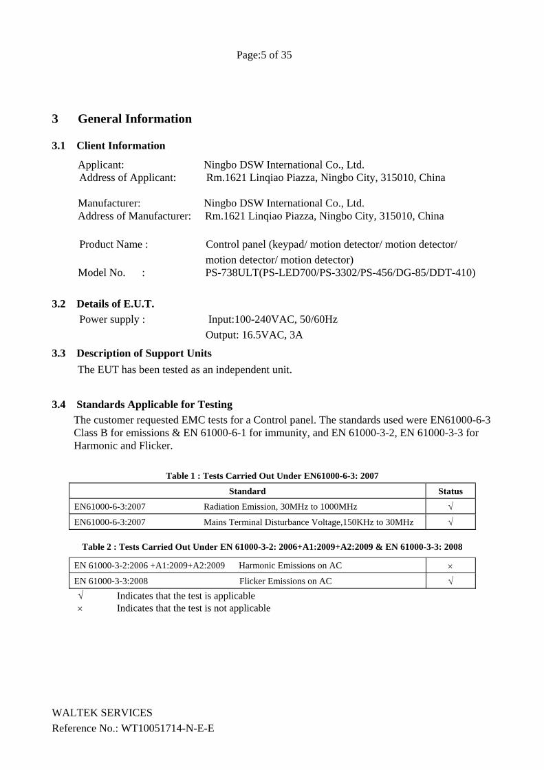
3 General Information
3.1 Client Information
Applicant: Ningbo DSW International Co., Ltd. Address of Applicant: Rm.1621 Linqiao Piazza, Ningbo City, 315010, China
Manufacturer: Ningbo DSW International Co., Ltd. Address of Manufacturer: Rm.1621 Linqiao Piazza, Ningbo City, 315010, China Product Name : Control panel (keypad/ motion detector/ motion detector/
motion detector/ motion detector) Model No. : PS-738ULT(PS-LED700/PS-3302/PS-456/DG-85/DDT-410)
3.2 Details of E.U.T. Power supply : Input:100-240VAC, 50/60Hz
Output: 16.5VAC, 3A
3.3 Description of Support Units The EUT has been tested as an independent unit.
3.4 Standards Applicable for Testing The customer requested EMC tests for a Control panel. The standards used were EN61000-6-3 Class B for emissions & EN 61000-6-1 for immunity, and EN 61000-3-2, EN 61000-3-3 for Harmonic and Flicker.
Table 1 : Tests Carried Out Under EN61000-6-3: 2007
Standard Status
EN61000-6-3:2007 Radiation Emission, 30MHz to 1000MHz √
EN61000-6-3:2007 Mains Terminal Disturbance Voltage,150KHz to 30MHz √
Table 2 : Tests Carried Out Under EN 61000-3-2: 2006+A1:2009+A2:2009 & EN 61000-3-3: 2008
EN 61000-3-2:2006 +A1:2009+A2:2009 Harmonic Emissions on AC ×
EN 61000-3-3:2008 Flicker Emissions on AC √ √ Indicates that the test is applicable × Indicates that the test is not applicable
Page:6 of 35
WALTEK SERVICES Reference No.: WT10051714-N-E-E
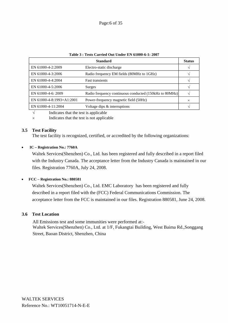
Table 3 : Tests Carried Out Under EN 61000-6-1: 2007
Standard Status EN 61000-4-2:2009 Electro-static discharge √ EN 61000-4-3:2006 Radio frequency EM fields (80MHz to 1GHz) √ EN 61000-4-4:2004 Fast transients √ EN 61000-4-5:2006 Surges √ EN 61000-4-6: 2009 Radio frequency continuous conducted (150kHz to 80MHz) √ EN 61000-4-8:1993+A1:2001 Power-frequency magnetic field (50Hz) × EN 61000-4-11:2004 Voltage dips & interruptions √ √ Indicates that the test is applicable × Indicates that the test is not applicable
3.5 Test Facility The test facility is recognized, certified, or accredited by the following organizations:
• IC – Registration No.: 7760A
Waltek Services(Shenzhen) Co., Ltd. has been registered and fully described in a report filed with the Industry Canada. The acceptance letter from the Industry Canada is maintained in our files. Registration 7760A, July 24, 2008.
• FCC – Registration No.: 880581
Waltek Services(Shenzhen) Co., Ltd. EMC Laboratory has been registered and fully described in a report filed with the (FCC) Federal Communications Commission. The acceptance letter from the FCC is maintained in our files. Registration 880581, June 24, 2008.
3.6 Test Location
All Emissions test and some immunities were performed at:- Waltek Services(Shenzhen) Co., Ltd. at 1/F, Fukangtai Building, West Baima Rd.,Songgang Street, Baoan District, Shenzhen, China
Page:7 of 35
WALTEK SERVICES Reference No.: WT10051714-N-E-E
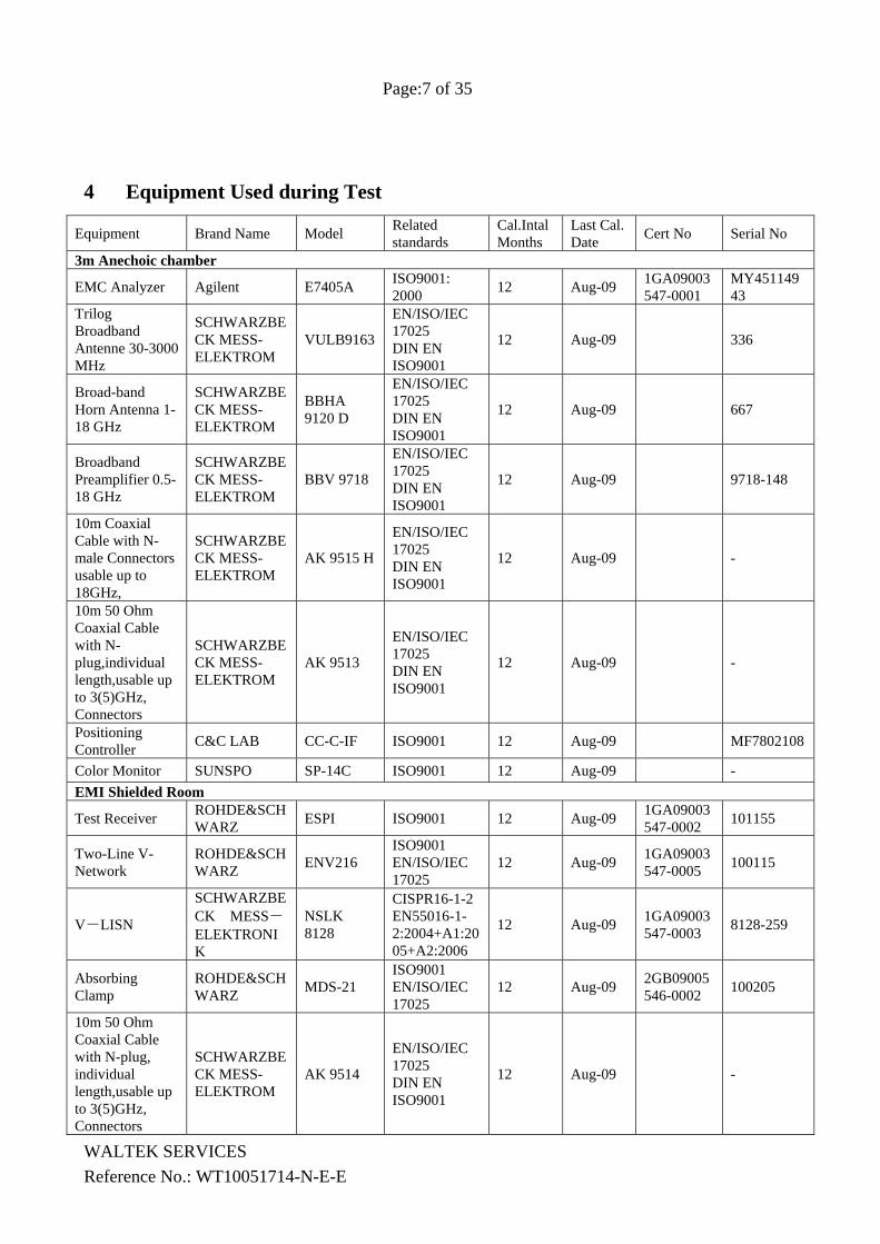
4 Equipment Used during Test
Equipment Brand Name Model Related standards
Cal.Intal Months
Last Cal. Date Cert No Serial No
3m Anechoic chamber
EMC Analyzer Agilent E7405A ISO9001: 2000 12 Aug-09 1GA09003
547-0001 MY45114943
Trilog Broadband Antenne 30-3000 MHz
SCHWARZBECK MESS-ELEKTROM
VULB9163
EN/ISO/IEC 17025 DIN EN ISO9001
12 Aug-09 336
Broad-band Horn Antenna 1-18 GHz
SCHWARZBECK MESS-ELEKTROM
BBHA 9120 D
EN/ISO/IEC 17025 DIN EN ISO9001
12 Aug-09 667
Broadband Preamplifier 0.5-18 GHz
SCHWARZBECK MESS-ELEKTROM
BBV 9718
EN/ISO/IEC 17025 DIN EN ISO9001
12 Aug-09 9718-148
10m Coaxial Cable with N-male Connectors usable up to 18GHz,
SCHWARZBECK MESS-ELEKTROM
AK 9515 H
EN/ISO/IEC 17025 DIN EN ISO9001
12 Aug-09 -
10m 50 Ohm Coaxial Cable with N-plug,individual length,usable up to 3(5)GHz, Connectors
SCHWARZBECK MESS-ELEKTROM
AK 9513
EN/ISO/IEC 17025 DIN EN ISO9001
12 Aug-09 -
Positioning Controller C&C LAB CC-C-IF ISO9001 12 Aug-09 MF7802108
Color Monitor SUNSPO SP-14C ISO9001 12 Aug-09 - EMI Shielded Room
Test Receiver ROHDE&SCHWARZ ESPI ISO9001 12 Aug-09 1GA09003
547-0002 101155
Two-Line V-Network
ROHDE&SCHWARZ ENV216
ISO9001 EN/ISO/IEC 17025
12 Aug-09 1GA09003547-0005 100115
V-LISN
SCHWARZBECK MESS-ELEKTRONIK
NSLK 8128
CISPR16-1-2 EN55016-1-2:2004+A1:2005+A2:2006
12 Aug-09 1GA09003547-0003 8128-259
Absorbing Clamp
ROHDE&SCHWARZ MDS-21
ISO9001 EN/ISO/IEC 17025
12 Aug-09 2GB09005546-0002 100205
10m 50 Ohm Coaxial Cable with N-plug, individual length,usable up to 3(5)GHz, Connectors
SCHWARZBECK MESS-ELEKTROM
AK 9514
EN/ISO/IEC 17025 DIN EN ISO9001
12 Aug-09 -
Page:8 of 35
WALTEK SERVICES Reference No.: WT10051714-N-E-E
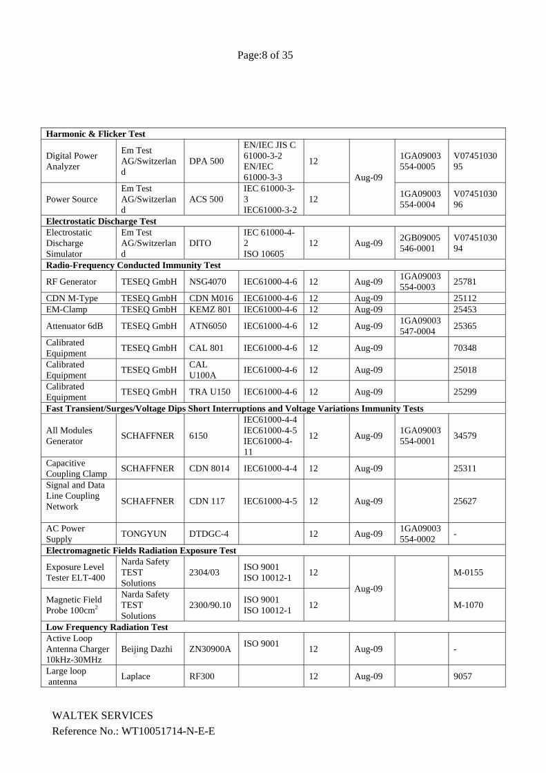
Harmonic & Flicker Test
Digital Power Analyzer
Em Test AG/Switzerland
DPA 500
EN/IEC JIS C 61000-3-2 EN/IEC 61000-3-3
12
Aug-09
1GA09003554-0005
V0745103095
Power Source Em Test AG/Switzerland
ACS 500 IEC 61000-3-3 IEC61000-3-2
12 1GA09003554-0004
V0745103096
Electrostatic Discharge Test Electrostatic Discharge Simulator
Em Test AG/Switzerland
DITO IEC 61000-4-2 ISO 10605
12 Aug-09 2GB09005546-0001
V0745103094
Radio-Frequency Conducted Immunity Test
RF Generator TESEQ GmbH NSG4070 IEC61000-4-6 12 Aug-09 1GA09003554-0003 25781
CDN M-Type TESEQ GmbH CDN M016 IEC61000-4-6 12 Aug-09 25112 EM-Clamp TESEQ GmbH KEMZ 801 IEC61000-4-6 12 Aug-09 25453
Attenuator 6dB TESEQ GmbH ATN6050 IEC61000-4-6 12 Aug-09 1GA09003547-0004 25365
Calibrated Equipment TESEQ GmbH CAL 801 IEC61000-4-6 12 Aug-09 70348
Calibrated Equipment TESEQ GmbH CAL
U100A IEC61000-4-6 12 Aug-09 25018
Calibrated Equipment TESEQ GmbH TRA U150 IEC61000-4-6 12 Aug-09 25299
Fast Transient/Surges/Voltage Dips Short Interruptions and Voltage Variations Immunity Tests
All Modules Generator SCHAFFNER 6150
IEC61000-4-4IEC61000-4-5IEC61000-4-11
12 Aug-09 1GA09003554-0001 34579
Capacitive Coupling Clamp SCHAFFNER CDN 8014 IEC61000-4-4 12 Aug-09 25311
Signal and Data Line Coupling Network
SCHAFFNER CDN 117 IEC61000-4-5 12 Aug-09 25627
AC Power Supply TONGYUN DTDGC-4 12 Aug-09 1GA09003
554-0002 -
Electromagnetic Fields Radiation Exposure Test
Exposure Level Tester ELT-400
Narda Safety TEST Solutions
2304/03 ISO 9001 ISO 10012-1 12
Aug-09
M-0155
Magnetic Field Probe 100cm2
Narda Safety TEST Solutions
2300/90.10 ISO 9001 ISO 10012-1 12 M-1070
Low Frequency Radiation Test Active Loop Antenna Charger 10kHz-30MHz
Beijing Dazhi ZN30900A ISO 9001 12 Aug-09 -
Large loop antenna Laplace RF300 12 Aug-09 9057
Page:9 of 35
5 Conducted Emission Test Results
5.1 Mains Terminals Disturbance Voltage, 150kHz to 30MHz
Test Requirement: EN61000-6-3 Class B Test Method: EN 55022 Class B Frequency Range: 150kHz to 30MHz Class/Severity: Class B Detector: Peak for pre-scan (9kHz Resolution Bandwidth)
Quasi-Peak & Average if maximised peak within 6dB of Average Limit
5.1.1 E.U.T. Operation
Operating Environment: Temperature: 25.5 °C Humidity: 51 % RH Atmospheric Pressure: 1012 mbar
EUT Operation :
Compliance test was performed in working mode.
The maximised peak emissions from the EUT was scanned and measured for both the Live and Neutral Lines. Quasi-peak & average measurements were performed if peak emissions were within 6dB of the average limit line.
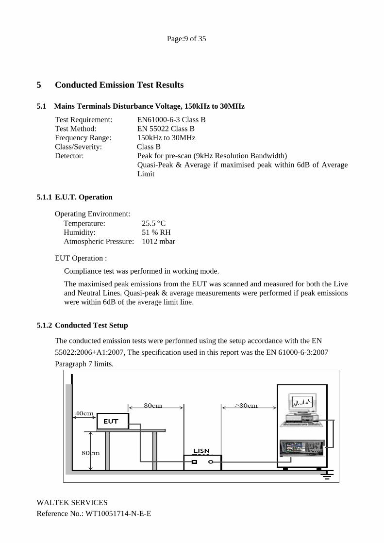
5.1.2 Conducted Test Setup
The conducted emission tests were performed using the setup accordance with the EN 55022:2006+A1:2007, The specification used in this report was the EN 61000-6-3:2007 Paragraph 7 limits.
WALTEK SERVICES Reference No.: WT10051714-N-E-E
Page:10 of 35
WALTEK SERVICES Reference No.: WT10051714-N-E-E
5.1.3 Measurement Data
An initial pre-scan was performed on the live and neutral lines.
No futher quasi-peak or average measurements were performed since no peak emissions were detected within 10dB line below the average limit.
Please refer to the following peak scan graph for reference.
Page:11 of 35
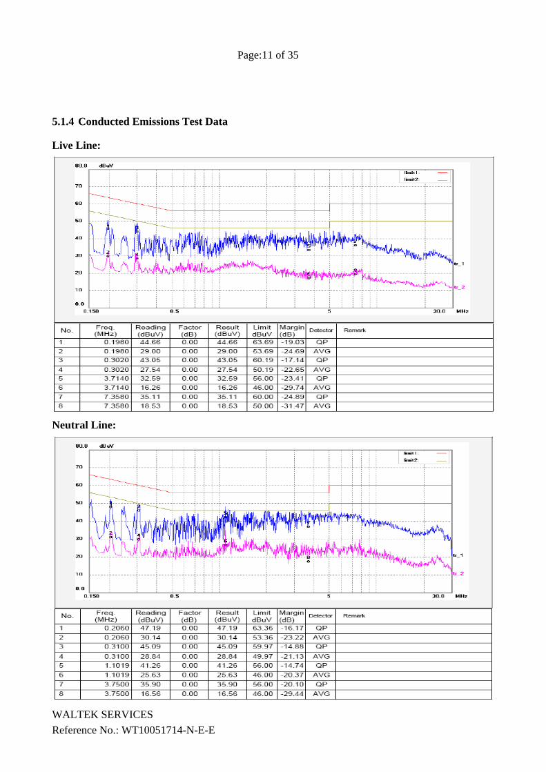
5.1.4 Conducted Emissions Test Data
Live Line:
Neutral Line:
WALTEK SERVICES Reference No.: WT10051714-N-E-E
Page:12 of 35
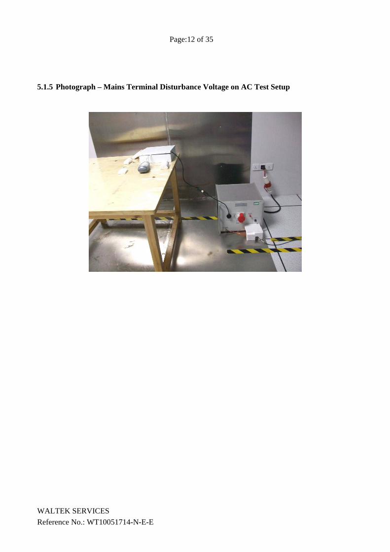
5.1.5 Photograph – Mains Terminal Disturbance Voltage on AC Test Setup
WALTEK SERVICES Reference No.: WT10051714-N-E-E
Page:13 of 35
5.2 Radiation Emission Data
Test Requirement: EN61000-6-3 Class B Test Method: EN 55022 Class B Frequency Range: 30MHz to 1000MHz Class/Severity: Class B Detector: Peak for pre-scan (120kHz Resolution Bandwidth)
Quasi-Peak & Average if maximised peak within 6dB of Average Limit
5.2.1 Measurement Uncertainty
All measurements involve certain levels of uncertainties, especially in the field of EMC. The factors contributing to uncertainties are spectrum analyzer, cable loss, antenna factor calibration, antenna directivity, antenna factor variation with height, antenna phase center variation, antenna factor frequency interpolation, measurement distance variation, site imperfections, mismatch (average), and system repeatability. Based on CISPR16-4-2, The Treatment of Uncertainty in EMC Measurements, the best estimate of the uncertainty of a radiation emissions measurement at Waltek EMC Lab is +5.03 dB.
5.2.2 Radiated Test Setup
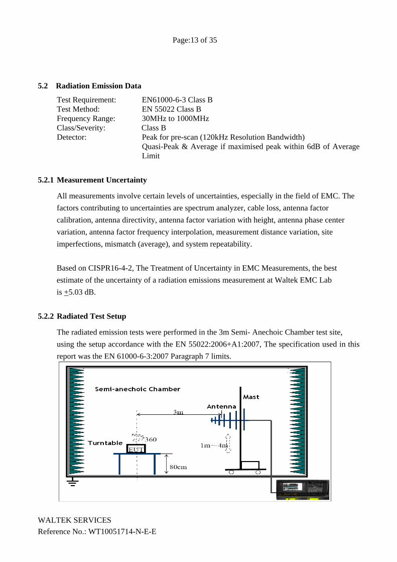
The radiated emission tests were performed in the 3m Semi- Anechoic Chamber test site, using the setup accordance with the EN 55022:2006+A1:2007, The specification used in this report was the EN 61000-6-3:2007 Paragraph 7 limits.
WALTEK SERVICES Reference No.: WT10051714-N-E-E
Page:14 of 35
WALTEK SERVICES Reference No.: WT10051714-N-E-E
5.2.3 Spectrum Analyzer Setup
According to EN55022 Class B Rules, the system was tested up to 1000 MHz.
Start Frequency .............................................. 30 MHz Stop Frequency .............................................. 1000 MHz Sweep Speed Auto
IF Bandwidth ............................................. 120KHz Video Bandwidth ........................................... 100kHz Quasi-Peak Adapter Bandwidth .................... 120 kHz Quasi-Peak Adapter Mode ............................ Normal Resolution Bandwidth ................................... 100kHz
5.2.4 Test procedure
For the radiated emissions test, maximizing procedure was performed on the six (6) highest emissions to ensure EUT is compliant with all installation combinations.
All data was recorded in the peak detection mode. Quasi-peak readings was performed only when an emission was found to be marginal (within +/-4 dBμV of specification limits), and are distinguished with a "Qp" in the data table. The EUT was under normal mode during the final qualification test and the configuration was used to represent the worst case results. Compliance test was performed in working mode, shock rating set at 1 and 9.While shock rating set at 9 had the worse test result ,which was shown below.
5.2.5 Corrected Amplitude & Margin Calculation
The Corrected Amplitude is calculated by adding the Antenna Factor and Cable Factor, and subtracting the Amplifier Gain from the Amplitude reading. The basic equation is as follows:
Corr. Ampl. = Indicated Reading + Antenna Factor + Cable Factor - Amplifier Gain
The “Margin” column of the following data tables indicates the degree of compliance with the applicable limit. For example, a margin of -7dBμV means the emission is 7dBμV below the maximum limit for Class B. The equation for margin calculation is as follows:
Margin = Corr. Ampl. – Class B Limit
Page:15 of 35
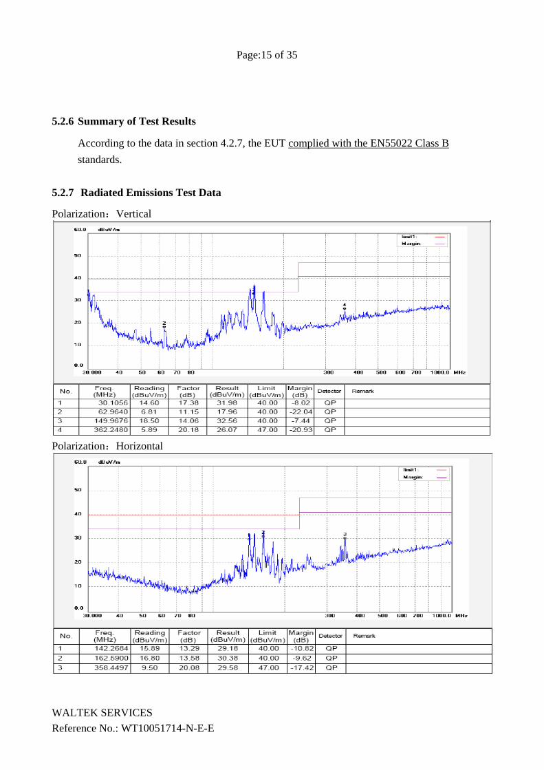
5.2.6 Summary of Test Results
According to the data in section 4.2.7, the EUT complied with the EN55022 Class B standards.
5.2.7 Radiated Emissions Test Data
Polarization:Vertical
Polarization:Horizontal
WALTEK SERVICES Reference No.: WT10051714-N-E-E
Page:16 of 35
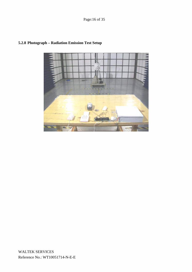
5.2.8 Photograph – Radiation Emission Test Setup
WALTEK SERVICES Reference No.: WT10051714-N-E-E
Page:17 of 35
WALTEK SERVICES Reference No.: WT10051714-N-E-E
5.3 Harmonics Test Results
Test Requirement: EN61000-3-2 Test Method: EN61000-3-2 Frequency Range: 100Hz to 2kHz Test Result: N/A There is no need for Harmonics test to be performed on this product (rated power is less than 75W) in accordance with EN61000-3-2 (2006). For further details, please refer to Clause 7, Note 1 of EN61000-3-2 which states:-
“For the following categories of equipment limits are not specified in this edition of the standard. Note 1: Equipment with a rated power of 75W or less, other than lighting equipment.”
Page:18 of 35
5.4 Flicker Test Result
Test Requirement: EN61000-3-3 Test Method: EN61000-3-3 Test Result PASS
Compliance test was performed in on mode and ‘on/off’ once during the test.
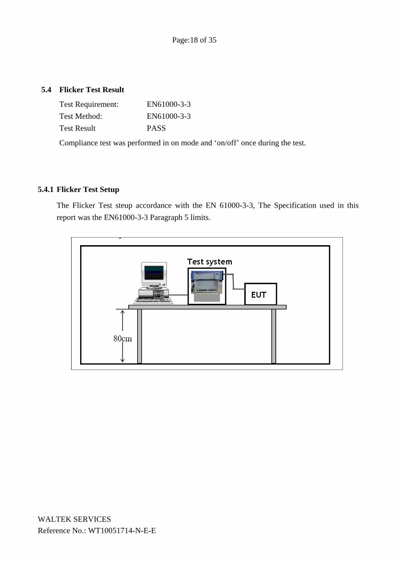
5.4.1 Flicker Test Setup
The Flicker Test steup accordance with the EN 61000-3-3, The Specification used in this report was the EN61000-3-3 Paragraph 5 limits.
WALTEK SERVICES Reference No.: WT10051714-N-E-E
Page:19 of 35
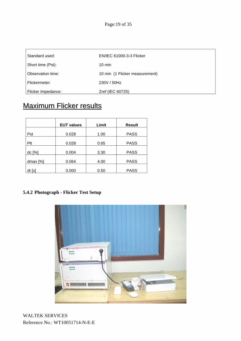
Standard used: EN/IEC 61000-3-3 Flicker
Short time (Pst): 10 min
Observation time: 10 min (1 Flicker measurement)
Flickermeter: 230V / 50Hz
Flicker Impedance: Zref (IEC 60725)
Maximum Flicker resultsMaximum Flicker results
EUT values Limit Result
Pst 0.028 1.00 PASS
Plt 0.028 0.65 PASS
dc [%] 0.004 3.30 PASS
dmax [%] 0.064 4.00 PASS
dt [s] 0.000 0.50 PASS
5.4.2 Photograph - Flicker Test Setup
WALTEK SERVICES Reference No.: WT10051714-N-E-E
Page:20 of 35
WALTEK SERVICES Reference No.: WT10051714-N-E-E
6 Immunity Test Results
6.1 Performance Criteria Description
Criterion A: The apparatus shall continue to operate as intended. No degradation of performance or loss of function is allowed below a performance level specified by the manufacturer, when the apparatus is used as intended.
Criterion B: The apparatus shall continue to operate as intended after the test. No degradation of performance or loss of function is allowed below a performance level specified by the manufacturer, when the apparatus is used as intended.
Criterion C: Temporary loss of function is allowed, provided the function is self recoverable or can be restored by the operation of the controls.
For further details, please refer to EN61000-6-1.
6.2 ESD Test Requirement: EN61000-6-1 Test Method: EN61000-4-2 Discharge Impedance: 330 Ω / 150 pF Discharge Voltage: Air Discharge: +/- 8 kV Contact Discharge: +/- 4 kV HCP & VCP: +/- 4 kV Polarity: Positive & Negative Number of Discharge: Minimum 10 times at each test point Discharge Mode: Single Discharge Discharge Period: 1 second minimum
6.2.1 E.U.T. Operation
Operating Environment: Temperature : 25.5 °C Humidity : 51 % RH Barometric Pressure : 1012 mbar
EUT Operation:
Compliance test was performed in working mode.
Page:21 of 35
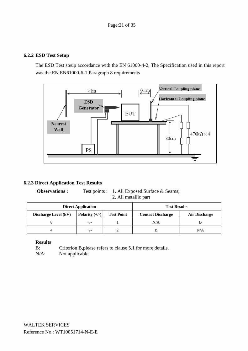
6.2.2 ESD Test Setup
The ESD Test steup accordance with the EN 61000-4-2, The Specification used in this report was the EN EN61000-6-1 Paragraph 8 requirements
6.2.3 Direct Application Test Results
Observations : Test points : 1. All Exposed Surface & Seams; 2. All metallic part
Direct Application Test Results
Discharge Level (kV) Polarity (+/-) Test Point Contact Discharge Air Discharge
8 +/- 1 N/A B
4 +/- 2 B N/A
Results B: Criterion B,please refers to clause 5.1 for more details. N/A: Not applicable.
WALTEK SERVICES Reference No.: WT10051714-N-E-E
Page:22 of 35
6.2.4 Indirect Application Test Results
Observations : Test points : 1. All sides.
Indirect Application Test Results
Discharge Level (kV) Polarity (+/-) Test Point Horizontal Coupling Vertical Coupling
4 +/- 1 B B
Results B: Criterion B,please refers to clause 5.1 for more details. N/A: Not applicable
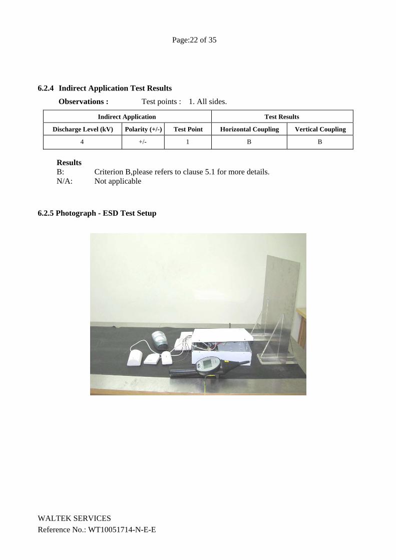
6.2.5 Photograph - ESD Test Setup
WALTEK SERVICES Reference No.: WT10051714-N-E-E
Page:23 of 35
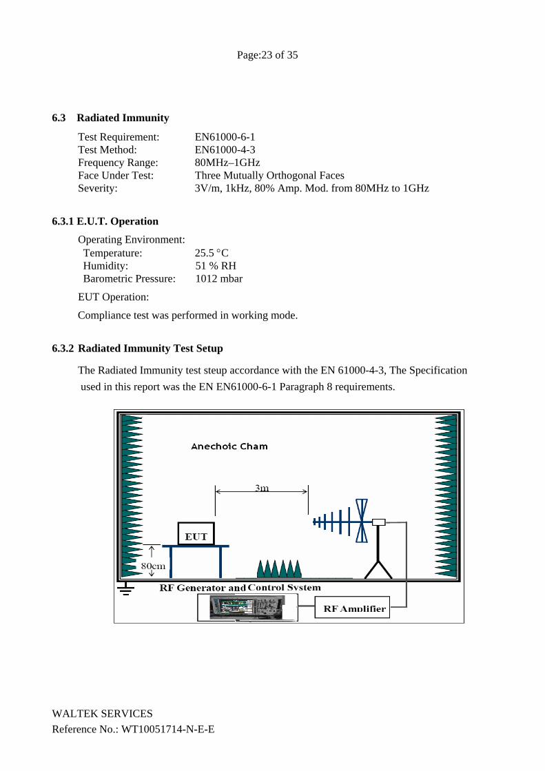
6.3 Radiated Immunity
Test Requirement: EN61000-6-1 Test Method: EN61000-4-3 Frequency Range: 80MHz–1GHz Face Under Test: Three Mutually Orthogonal Faces Severity: 3V/m, 1kHz, 80% Amp. Mod. from 80MHz to 1GHz
6.3.1 E.U.T. Operation
Operating Environment: Temperature: 25.5 °C Humidity: 51 % RH Barometric Pressure: 1012 mbar
EUT Operation:
Compliance test was performed in working mode.
6.3.2 Radiated Immunity Test Setup
The Radiated Immunity test steup accordance with the EN 61000-4-3, The Specification used in this report was the EN EN61000-6-1 Paragraph 8 requirements.
WALTEK SERVICES Reference No.: WT10051714-N-E-E
Page:24 of 35
6.3.3 Test Results
Frequency Level Modulation EUT Face Result / Observations
80MHz-1GHz 3V/m 1kHz, 80%,
Amp. Mod.
X Y Z
During test and
after test, the EUT was normal (A).
Remarks: AM : Amplitude Modulation. PM : Pulse Modulation. X : EUT as per photograph in section 6.3.4 of this report. Y : As X, but rotate EUT by 90° clockwise. Z : As Y, but rotate EUT by 90° vertically.
Results A : No degradation in the performance of the E.U.T. was observed.
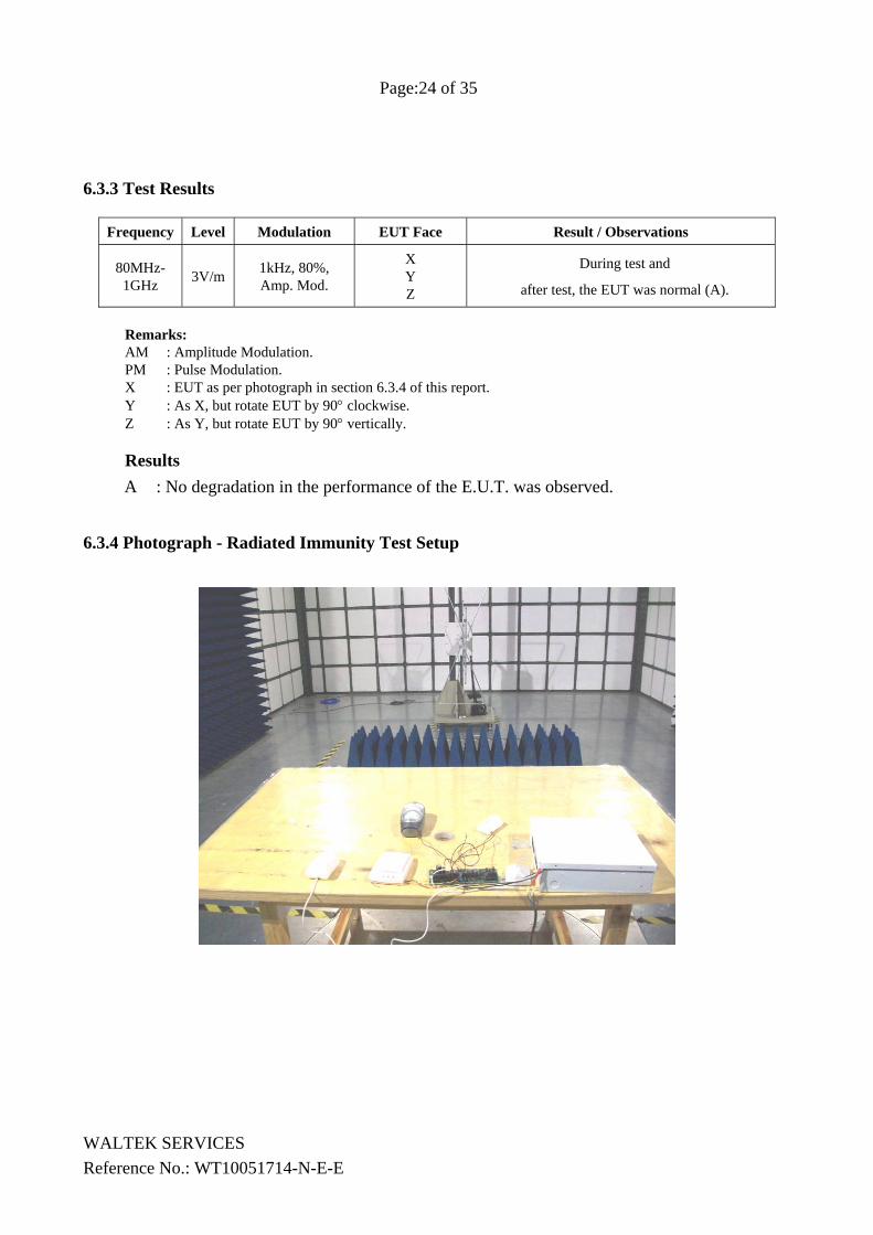
6.3.4 Photograph - Radiated Immunity Test Setup
WALTEK SERVICES Reference No.: WT10051714-N-E-E
Page:25 of 35
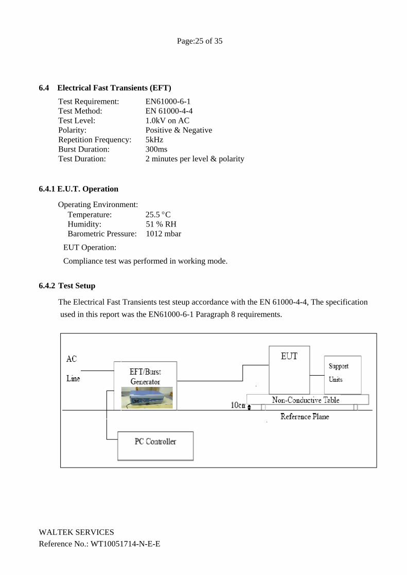
6.4 Electrical Fast Transients (EFT)
Test Requirement: EN61000-6-1 Test Method: EN 61000-4-4 Test Level: 1.0kV on AC Polarity: Positive & Negative Repetition Frequency: 5kHz Burst Duration: 300ms Test Duration: 2 minutes per level & polarity
6.4.1 E.U.T. Operation
Operating Environment: Temperature: 25.5 °C Humidity: 51 % RH Barometric Pressure: 1012 mbar
EUT Operation:
Compliance test was performed in working mode.
6.4.2 Test Setup
The Electrical Fast Transients test steup accordance with the EN 61000-4-4, The specification used in this report was the EN61000-6-1 Paragraph 8 requirements.
WALTEK SERVICES Reference No.: WT10051714-N-E-E
Page:26 of 35
6.4.3 Test Results On AC Cable
Lead under Test
Level (±kV)
Coupling Direct/Clamp EUT operating mode
Observations (Performance Criterion)
AC Live ±1.0 ±0.5 Direct ON and Idle mode B
AC Neutral ±1.0 ±0.5 Direct ditto ditto
AC Live & Neutral
±1.0 ±0.5 Direct ditto ditto
Results B: Criterion B,please refers to clause 5.1 for more details.
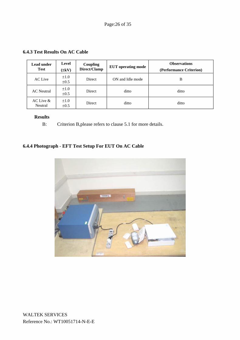
6.4.4 Photograph - EFT Test Setup For EUT On AC Cable
WALTEK SERVICES Reference No.: WT10051714-N-E-E
Page:27 of 35
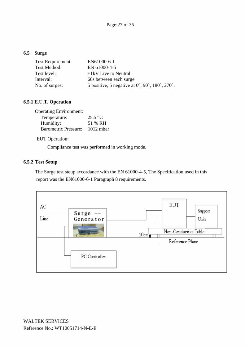
6.5 Surge
Test Requirement: EN61000-6-1 Test Method: EN 61000-4-5 Test level: ±1kV Live to Neutral Interval: 60s between each surge No. of surges: 5 positive, 5 negative at 0°, 90°, 180°, 270°.
6.5.1 E.U.T. Operation
Operating Environment: Temperature: 25.5 °C Humidity: 51 % RH Barometric Pressure: 1012 mbar
EUT Operation:
Compliance test was performed in working mode.
6.5.2 Test Setup
The Surge test steup accordance with the EN 61000-4-5, The Specification used in this report was the EN61000-6-1 Paragraph 8 requirements.
WALTEK SERVICES Reference No.: WT10051714-N-E-E
Page:28 of 35
6.5.3 Test Results
Level Voltage Poll Path Pass Fail 1 0.5kV ± L-N / /
2 1kV ± L-N B /
3 2kV ± L-PE, L-N, N-PE / /
4 4kV ± L-PE, L-N, N-PE / /
Results
B: Criterion B,please refers to clause 5.1 for more details.
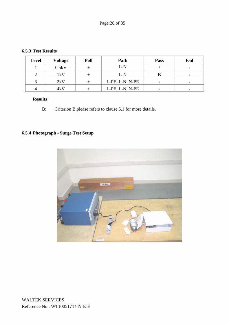
6.5.4 Photograph - Surge Test Setup
WALTEK SERVICES Reference No.: WT10051714-N-E-E
Page:29 of 35
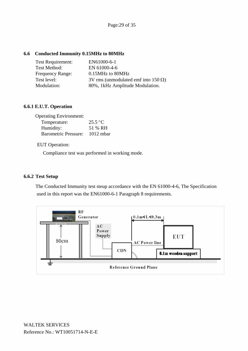
6.6 Conducted Immunity 0.15MHz to 80MHz
Test Requirement: EN61000-6-1 Test Method: EN 61000-4-6 Frequency Range: 0.15MHz to 80MHz Test level: 3V rms (unmodulated emf into 150 Ω) Modulation: 80%, 1kHz Amplitude Modulation.
6.6.1 E.U.T. Operation
Operating Environment: Temperature: 25.5 °C Humidity: 51 % RH Barometric Pressure: 1012 mbar
EUT Operation:
Compliance test was performed in working mode.
6.6.2 Test Setup
The Conducted Immunity test steup accordance with the EN 61000-4-6, The Specification used in this report was the EN61000-6-1 Paragraph 8 requirements.
WALTEK SERVICES Reference No.: WT10051714-N-E-E
Page:30 of 35
6.6.3 Test Results AC mains of EUT
Frequency Line Test Level Modulation Step Size
Dwell Time
Observation (Performance Criterion)
150kHz to 80MHz
2 Wire AC Supply Cable
3Vrms 80%, 1kHz Amp. Mod.
1% 1s During test and
after test,the EUT was normal (A).
Results
A: No degradation in the performance of the E.U.T. was observed.
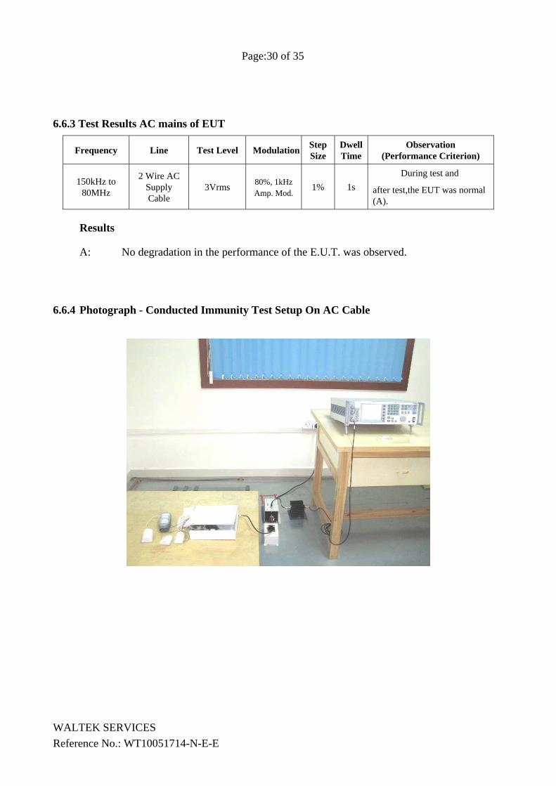
6.6.4 Photograph - Conducted Immunity Test Setup On AC Cable
WALTEK SERVICES Reference No.: WT10051714-N-E-E
Page:31 of 35
6.7 Voltage Dips and Interruptions Test Requirement: EN 61000-6-1 Test Method: EN 61000-4-11 Test Level: 100% & 60% & 30 % of UT (Supply Voltage) No. of Dips / Interruptions: 1 per Level at 20ms intervals
6.7.1 E.U.T. Operation
Operating Environment: Temperature: 25.5 °C Humidity: 51 % RH Barometric Pressure: 1012 mbar
EUT Operation:
Compliance test was performed in working mode.
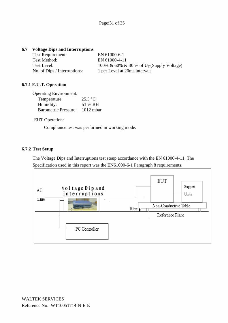
6.7.2 Test Setup
The Voltage Dips and Interruptions test steup accordance with the EN 61000-4-11, The Specification used in this report was the EN61000-6-1 Paragraph 8 requirements.
WALTEK SERVICES Reference No.: WT10051714-N-E-E
Page:32 of 35
6.7.3 Measurement Data
EUT operating
mode
Dropout % UT Phase
Duration of dropout in Periods
No of dropout
Time between dropout
Observations (Performance Criterion)
On modes 95 0° and180° 0.5 3 10ms C
ditto 95 0° and180° 250 3 200ms B
ditto 30 0° and180° 25 3 1000ms B
Results B & C: During test, This was within the minimum performance criteria set by the
applicant. Please refer to section 5.7.4 of this report for further details.
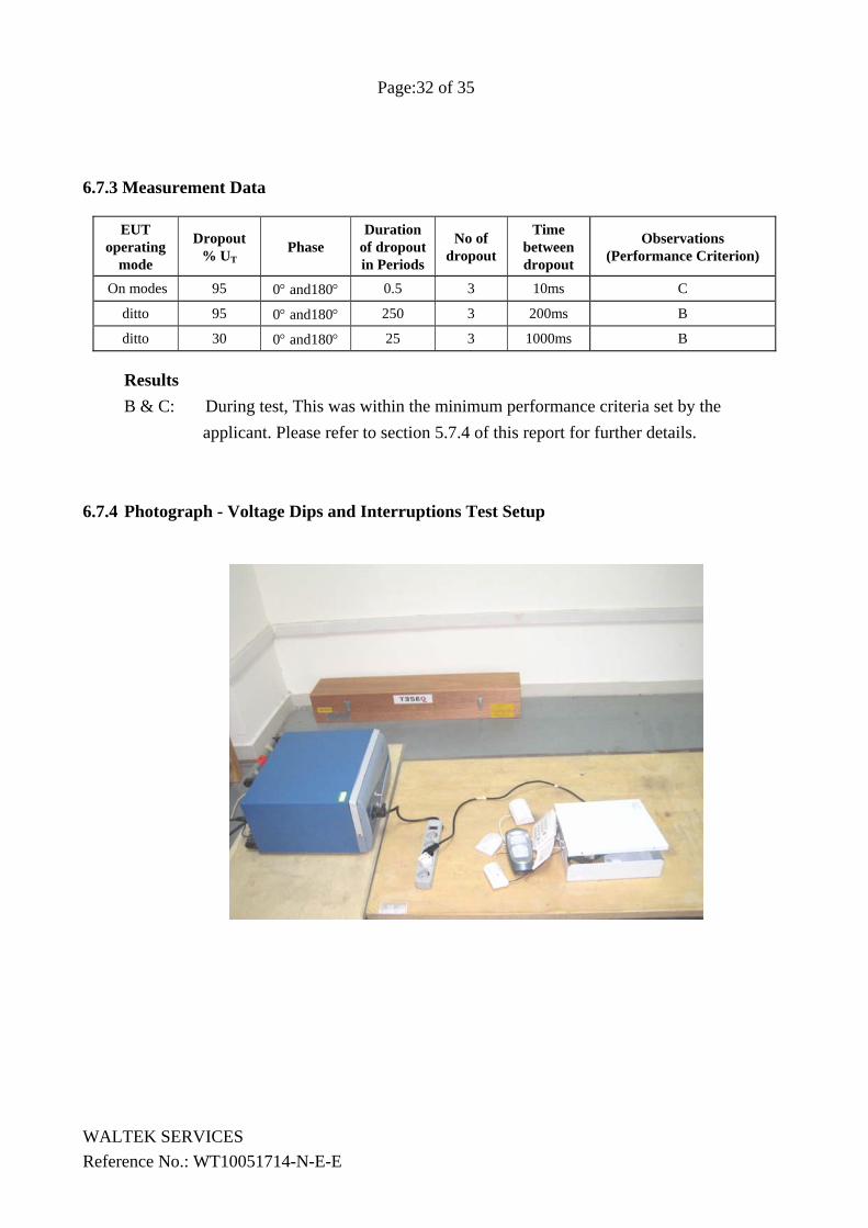
6.7.4 Photograph - Voltage Dips and Interruptions Test Setup
WALTEK SERVICES Reference No.: WT10051714-N-E-E
Page:33 of 35
7 Photographs - Constructional Details
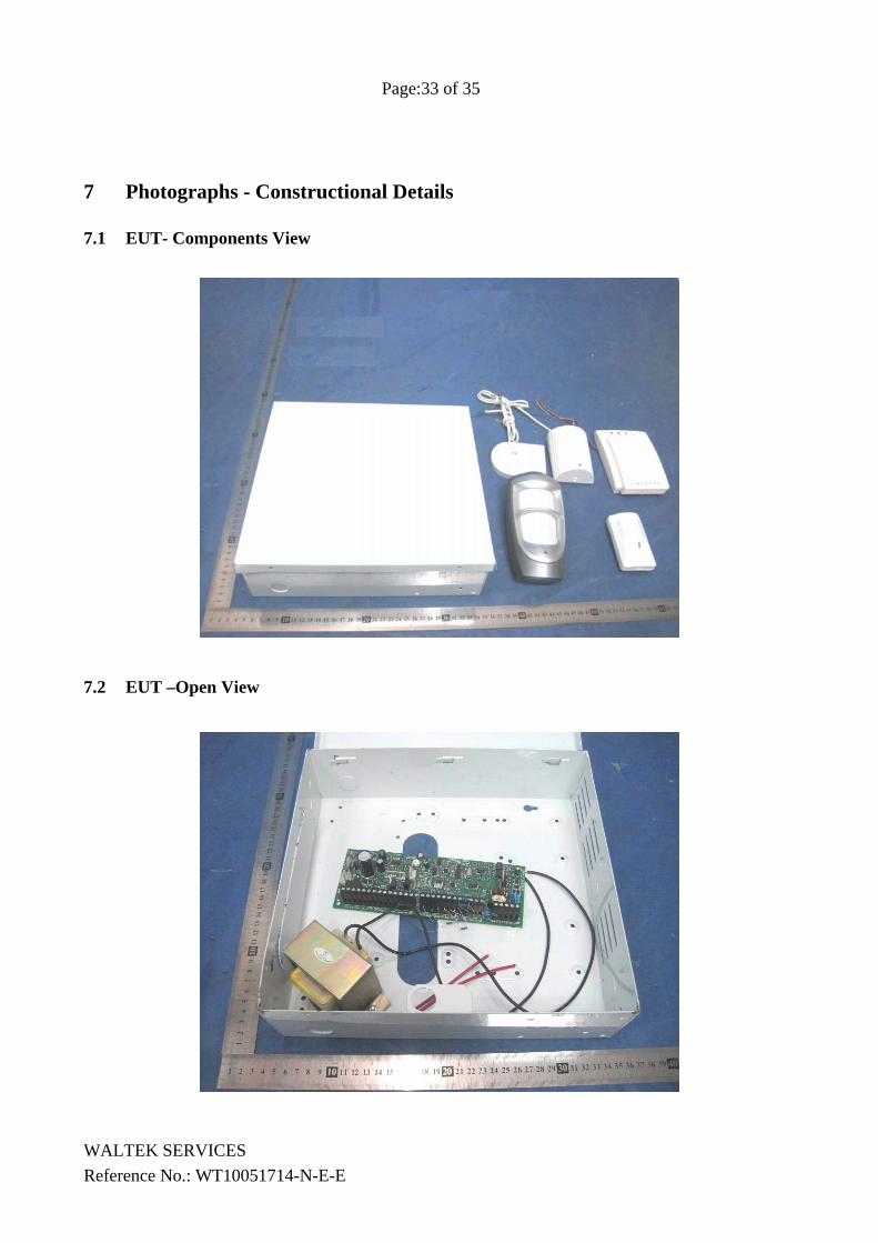
7.1 EUT- Components View
7.2 EUT –Open View
WALTEK SERVICES Reference No.: WT10051714-N-E-E
Page:34 of 35
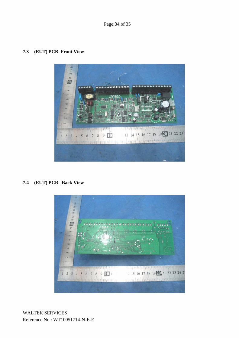
7.3 (EUT) PCB–Front View
7.4 (EUT) PCB –Back View
WALTEK SERVICES Reference No.: WT10051714-N-E-E
Page:35 of 35
WALTEK SERVICES Reference No.: WT10051714-N-E-E
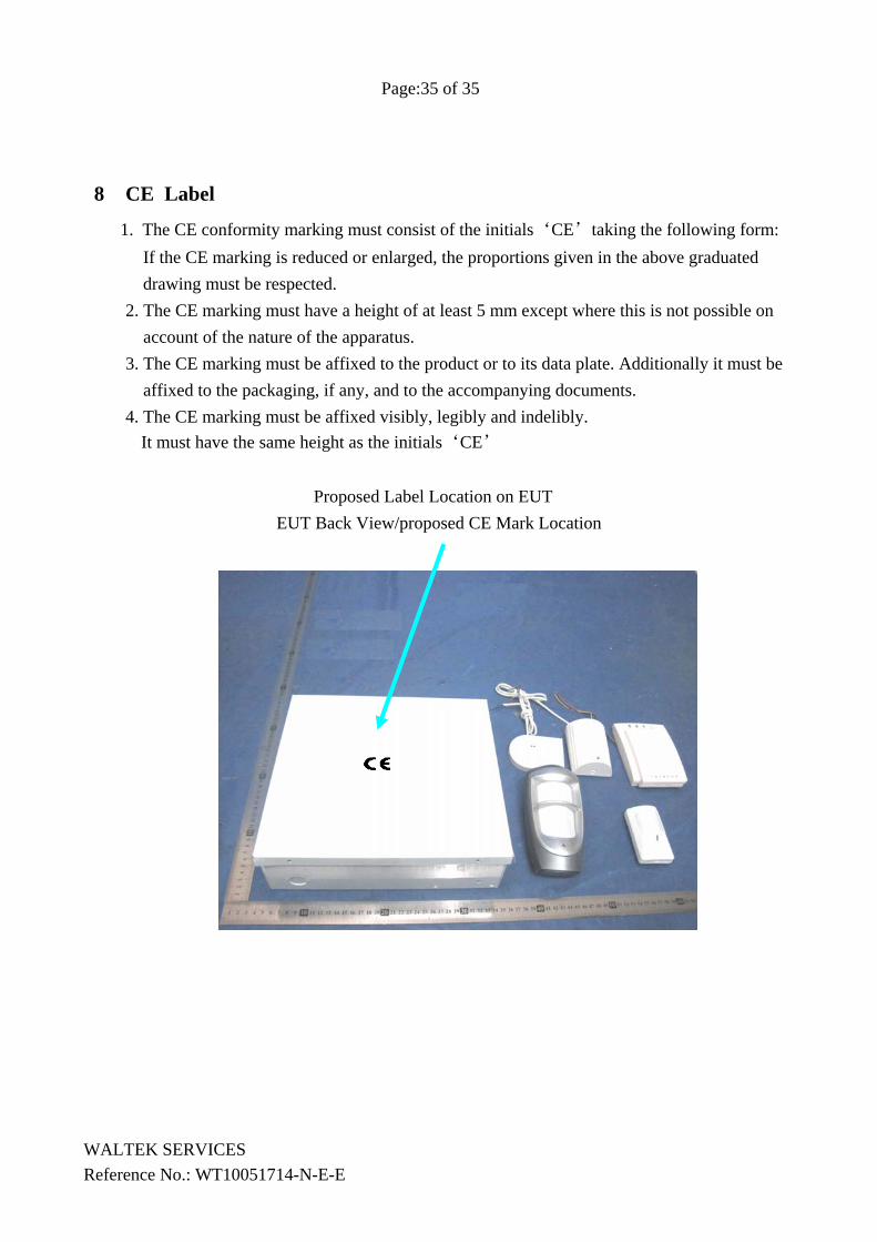
8 CE Label
1. The CE conformity marking must consist of the initials‘CE’taking the following form: If the CE marking is reduced or enlarged, the proportions given in the above graduated drawing must be respected.
2. The CE marking must have a height of at least 5 mm except where this is not possible on account of the nature of the apparatus.
3. The CE marking must be affixed to the product or to its data plate. Additionally it must be affixed to the packaging, if any, and to the accompanying documents.
4. The CE marking must be affixed visibly, legibly and indelibly. It must have the same height as the initials‘CE’
Proposed Label Location on EUT EUT Back View/proposed CE Mark Location