Embed Size (px)
Citation preview

Global No.1 Testing Laboratory Universal Certification Solution
EMC TEST REPORT
Product name: Digital Voice Recorder (Voice Tracer)
Models: DVT2710, DVT2700, DVT2510, DVT2500 Standards: EN 55032:2012/AC:2013
EN 55024:2010
AS/NZS CISPR 22:2009 + A1:2010
Applicant: ZARAM TECHNOLOGY INC.
Test Report No.: UCSCE-1604-036
UCS Co., Ltd.
#702, AnyangMegavalley, 268 Hagui-ro, Dongan-gu, Anyang-si, Gyeonggi-do, 14056 Korea. Tel: +82-1833-5681 / Fax: +82-31-420-5685 / Open Site: +82-31-355-2666
Online: http://www.ucs.co.kr

Page: 2 of 39 Report Number: UCSCE-1604-036
UQE-TRF-01(Rev.0)
EMC TEST REPORT Report Number UCSCE-1604-036
Applicant
Company Name
ZARAM TECHNOLOGY INC.
Address 41, Seongnam-daero 925beon-gil, Bundang-gu, Seongnam-si, Gyeonggi-do, Korea
Product
Product Name Digital Voice Recorder (Voice Tracer)
Model Name DVT2710
Family Model Name
DVT2700, DVT2510, DVT2500
Manufacturer ZARAM TECHNOLOGY INC.
Serial No. -
Other
Receipt Date 2016.03.25 Receipt Number UCS-R-2016-0209
Issued Date 2016.04.07 Tested Date 2016.03.25 ~ 2016.03.29
Standard
EN 55032:2012/AC:2013
EN 55024:2010
AS/NZS CISPR 22:2009 + A1:2010
Tested by
J. H. Park (Sign)
Approved by
Y. M. Choi (Sign)
UCS Co., Ltd.
#702, AnyangMegavally, 268 Hagui-ro, Dongan-gu, Anyang-si, Gyeonggi-do, 14056 Korea. Tel : +82-1833-5681, Fax : +82-31-420-5685
o This is certified that the above mentioned products have been tested for the sample provided by client. o No part of this document may not be duplicated or reproduced by any means without the express written permission of UCS Co., Ltd.

Page: 3 of 39 Report Number: UCSCE-1604-036
UQE-TRF-01(Rev.0)
Contents
1. Applicant Information ........................................................................................................................................................4
2. EUT (Equipment under test) Information ..........................................................................................................................4
3. Laboratory Information ......................................................................................................................................................4
4. Test Configuration and Condition ......................................................................................................................................5
5. Summary of Test Results ....................................................................................................................................................7
6. Test Results ........................................................................................................................................................................8
7. EUT Photos ......................................................................................................................................................................36
Revision History
Issued Report No. Issued Date Revisions Effect Section
UCSCE-1604-036 07-Apr-2016 Initial Issue All

Page: 4 of 39 Report Number: UCSCE-1604-036
UQE-TRF-01(Rev.0)
1. Applicant Information
Applicant Name : ZARAM TECHNOLOGY INC. Address : 41, Seongnam-daero 925beon-gil, Bundang-gu, Seongnam-si, Gyeonggi-do, Korea
Manufacturer : ZARAM TECHNOLOGY INC. Address : 41, Seongnam-daero 925beon-gil, Bundang-gu, Seongnam-si, Gyeonggi-do, Korea
Factory : T.B.M COMMUNICATION Co. Address : 411-ho, Humanskyvalley, 33, 132beon-gil, Omokcheon-ro, Gwonseon-gu, Suwon-si, Gyeonggi-do, Korea
2. EUT (Equipment under test) Information
Product Name : Digital Voice Recorder (Voice Tracer) Basic Model : DVT2710 Family Model : DVT2700, DVT2510, DVT2500
* All components of these models are same but only classified as marketing purpose. (buyer’s request.)
* Applicant consigns only basic model to test. Therefore this test report just guarantees the units, which have been tested.
* The Applicant/manufacturer is responsible for the compliance of all variants.
Max Clock : 500 MHz Battery : 2 x AAA alkaline batteries USB : High-speed 2.0 Micro USB Earphone : Stereo jack , 3.5 mm Display : 1.77 " (Resolution: 128 pixels x 160 pixels) External memory : micro SD card (SDHC) supporting up to 32 GB Internal memory : NAND Flash 8 GB Recording time : PCM - 12.5 h, SHQ - 94 h, HQ - 188 h, SP - 282.5 h, LP - 2,261.5 h Recording format : PCM – WAV, 1,411 kbits/s, SHQ – MP3, 192 kbits/s, HQ – MP3, 96 kbits/s, SP – MP3,
64 kbits/s, LP – MP3, 8 kbits/s Speaker : Frequency 70 kHz ~ 15 kHz, Maximum output 110 mW Dimensions : 45 mm × 113 mm × 20 mm Weight : 83 g (Batteries / rechargeable batteries included) PC System Requirements: OS – Window 10,8,7, Vista, Mac OS X, Linux Battery life : LP mode recording (Internal memory / microSD memory),
Max. 50 h / 25 h (Alkaline batteries Sampling frequency : PCM/SHQ – 44.1 kHz, HQ – 32 kHz, SP – 22 kHz, LP – 16 kHz Operating temperature : 5 ºC - 45 ºC / 41 ºF - 113 ºF Humidity : 10 % R.H. - 90 % R.H.
* Product specification information described herein was obtained from product data sheet or user’s manual.
3. Laboratory Information
Laboratory Name : UCS Co., Ltd. Location : 35-13, Hwalcho-gil,109beon-gil, Namyang-eup, Hwaseong-si, Gyeonggi-do, 18278 Korea.
Page: 5 of 39 Report Number: UCSCE-1604-036
UQE-TRF-01(Rev.0)
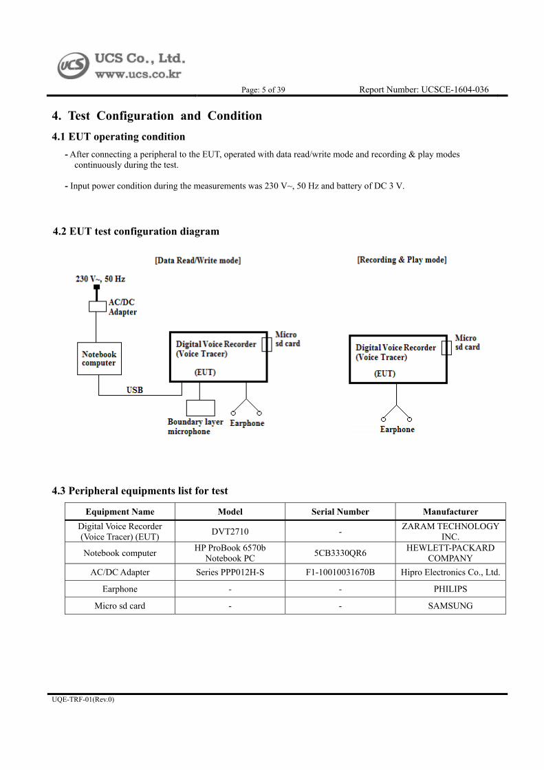
4. Test Configuration and Condition 4.1 EUT operating condition
- After connecting a peripheral to the EUT, operated with data read/write mode and recording & play modes continuously during the test.
- Input power condition during the measurements was 230 V~, 50 Hz and battery of DC 3 V.
4.2 EUT test configuration diagram
4.3 Peripheral equipments list for test
Equipment Name Model Serial Number Manufacturer
Digital Voice Recorder (Voice Tracer) (EUT)
DVT2710 - ZARAM TECHNOLOGY
INC.
Notebook computer HP ProBook 6570b
Notebook PC 5CB3330QR6
HEWLETT-PACKARD COMPANY
AC/DC Adapter Series PPP012H-S F1-10010031670B Hipro Electronics Co., Ltd.
Earphone - - PHILIPS
Micro sd card - - SAMSUNG
Page: 6 of 39 Report Number: UCSCE-1604-036
UQE-TRF-01(Rev.0)
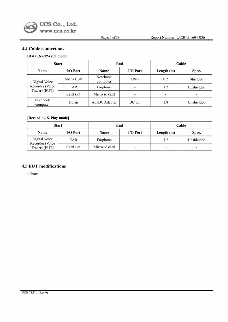
4.4 Cable connections
[Data Read/Write mode]
Start End Cable
Name I/O Port Name I/O Port Length (m) Spec.
Digital Voice Recorder (Voice Tracer) (EUT)
Micro USB Notebook computer
USB 0.2 Shielded
EAR Earphone - 1.2 Unshielded
Card slot Micro sd card - - -
Notebook computer
DC in AC/DC Adapter DC out 1.8 Unshielded
[Recording & Play mode]
Start End Cable
Name I/O Port Name I/O Port Length (m) Spec.
Digital Voice Recorder (Voice Tracer) (EUT)
EAR Earphone - 1.2 Unshielded
Card slot Micro sd card - - -
4.5 EUT modifications
- None

Page: 7 of 39 Report Number: UCSCE-1604-036
UQE-TRF-01(Rev.0)
5. Summary of Test Results 5.1 Summary of test results
Standard Test Item Results
EN 55032:2012/AC:2013
AS/NZS CISPR 22:2009
+ A1:2010,
Conducted emissions at the AC mains power ports Met Class B / Pass
Asymmetric mode conducted emissions N/A (See Note 1)
Conducted differential voltage emissions N/A (See Note 2)
Radiated emissions Met Class B / Pass
EN 61000-3-2:2014 Harmonics current emissions N/A (See Note 3)
EN 61000-3-3:2013 Voltage changes, Voltage fluctuations and flicker
EN 55024:2010
Electrostatic discharge Met Criterion A / Pass
Radiated RF electromagnetic field immunity Met Criterion A / Pass
Electrical fast transient/burst immunity Met Criterion A / Pass
Surge immunity Met Criterion A / Pass
Conducted disturbance induced by RF fields immunity Met Criterion A / Pass
Magnetic field immunity N/A (See Note 4)
Voltage dips and short interruptions N/A (See Note 3)
* Note 1: This test is not performed because the EUT is does not have asymmetric mode * Note 2: This test is not performed because the EUT is does not have TV/FM broadcast receiver tuner ports and RF modulator
output ports. * Note 3: This test is not performed because the EUT is operated by USB power and battery. * Note 4: The EUT does not contain devices susceptible to magnetic fields, so the test was not performed.
5.2 Performance of criteria
Performance criterion A During and after the test the EUT shall continue to operate as intended without operator intervention. No degradation of performance or loss of function is allowed below a minimum performance level specified by the manufacturer when the EUT is used as intended. The performance level may be replaced by a permissible loss of performance. If the minimum performance level or the permissible performance loss is not specified by the manufacturer, then either of these may be derived from the product description and documentation, and by what the user may reasonably expect from the EUT if used as intended.
Performance criterion B After the test, the EUT shall continue to operate as intended without operator intervention. No degradation of performance or loss of function is allowed, after the application of the phenomena below a performance level specified by the manufacturer, when the EUT is used as intended. The performance level may be replaced by a permissible loss of performance. During the test, degradation of performance is allowed. However, no change of operating state or stored data is allowed to persist after the test. If the minimum performance level (or the permissible performance loss) is not specified by the manufacturer, then either of these may be derived from the product description and documentation, and by what the user may reasonably expect from the EUT if used as intended.
Performance criterion C During and after testing, a temporary loss of function is allowed, provided the function is selfrecoverable, or can be restored by the operation of the controls or cycling of the power to the EUT by the user in accordance with the manufacturer’s instructions. Functions, and/or information stored in non-volatile memory, or protected by a battery backup, shall not be lost.

Page: 8 of 39 Report Number: UCSCE-1604-036
UQE-TRF-01(Rev.0)
6. Test Results
6.1 Conducted emissions
Test Standard EN 55032:2012/AC:2013, AS/NZS CISPR 22:2009 + A1:2010, Class B
Tested Date 2016.03.25
Input Ratings 230 V~, 50 Hz
Temperature 22.8 °C Humidity 30.1 % R.H.
Test result Met Class B / Pass
6.1.1 Limit
AC mains power ports
Frequency range [MHz] Coupling device Detector type /
bandwidth Class A limits [dBμV]
0.15 ~ 0.5 AMN Quasi Peak / 9 kHz
79
0.5 ~ 30 73
0.15 ~ 0.5 AMN Average / 9 kHz
66
0.5 ~ 30 60
Asymmetric mode
Frequency range [MHz] Coupling device Detector type /
bandwidth Class A voltage limits
[dBμV]
0.15 ~ 0.5 AAN Quasi Peak / 9 kHz
97 ~ 87
0.5 ~ 30 87
0.15 ~ 0.5 AAN Average / 9 kHz
84 ~ 74
0.5 ~ 30 74
6.1.2 Test set-up and procedure
The mains terminal disturbance voltage was measured with the equipment under test (EUT) in a shield room.
The EUT was connected to an artificial mains network (LISN) placed on the floor.
The EUT was placed on non-metallic table 0.8 m above the metallic, grounded floor.
Amplitude measurements were performed with a quasi-peak detector and an average detector.
6.1.3 Measurement uncertainty
Conducted emission, quasi-peak detection: 1.8 dB
Conducted emission, average detection: 1.8 dB
The measurement uncertainty is given with a confidence of 95 % with the coverage factor, k = 2.

Page: 9 of 39 Report Number: UCSCE-1604-036
UQE-TRF-01(Rev.0)
6.1.4 Test equipment used
Equipment Model Serial No. Vendor Next Cal. Date Use
Test Receiver ESPI3 101171 ROHDE & SCHWARZ
2016.08.04
Test Receiver ESR7 101120 ROHDE & SCHWARZ
2016.08.04
LISN NSLK 8127 8127518 SCHWARZBECK 2016.08.05
Two-Line V-Network
ENV216 3560.6550.12-
101874-Rq ROHDE & SCHWARZ
2016.08.04
LISN L3-32 1220X20311 PMM 2016.08.05
ISN ISN T800 30813 TESEQ 2017.02.05
ISN ISN T8-Cat6 29709 TESEQ 2017.02.05

Page: 10 of 39 Report Number: UCSCE-1604-036
UQE-TRF-01(Rev.0)
6.1.5 Test set-up photos
[Data Read/Write mode]
[Front view]
[Rear view]

Page: 11 of 39 Report Number: UCSCE-1604-036
UQE-TRF-01(Rev.0)
6.1.6 Test data
- Test Frequency rang : 150 kHz ~ 30 MHz - Bandwidth : 9 kHz
[Data Read/Write mode]
Frequency Factor
Line
Quasi-Peak Average
LISN Cable Limit Reading Results Limit Reading Results
[MHz] [dB] [dB] [dBμV] [dBμV] [dBμV] [dBμV] [dBμV] [dBμV]
0.15 9.73 0.04 N 66.00 34.27 44.04 56.00 - -
0.23 9.71 0.05 N 62.45 36.37 46.13 52.45 - -
0.66 9.85 0.09 N 56.00 36.05 45.99 46.00 - -
1.32 9.71 0.12 N 56.00 32.60 42.43 46.00 - -
4.65 9.67 0.28 N 56.00 23.63 33.58 46.00 - -
17.45 9.75 0.61 N 60.00 27.33 37.69 50.00 - -
* Remark: “H” Hot Line, “N” Neutral Line * Average mode was not recorded, because Quasi-Peak values were under the Average limit.
* Results [dBμV] = Reading [dBμV] + LISN [dB] + Cable [dB]

Page: 12 of 39 Report Number: UCSCE-1604-036
UQE-TRF-01(Rev.0)
6.1.7 Test graph
[Data Read/Write mode]
[Hot line]
* : Quasi-Peak, : Average
[Neutral line]
* : Quasi-Peak, : Average

Page: 13 of 39 Report Number: UCSCE-1604-036
UQE-TRF-01(Rev.0)
6.2 Radiated emissions (below 1 GHz)
Test Standard EN 55032:2012/AC:2013, AS/NZS CISPR 22:2009 + A1:2010, Class B
Tested Date 2016.03.25
Input Ratings 230 V~, 50 Hz / DC 3 V (Battery)
Temperature (25.7 ± 0.2) °C Humidity (23.8 ± 0.2) % R.H.
Test result Met Class B / Pass
6.2.1 Limit
Frequency range
[MHz]
Measurement Class A limits [dBμV]
Distance [m] Detector type /
bandwidth OATS/SAC
30 ~ 230 10
Quasi Peak / 120 kHz
30
230 ~ 1 000 37
30 ~ 230 3
40
230 ~ 1 000 47
6.2.2 Test set-up and procedure
A pretest was performed at 3 m distance in a semi-anechoic chamber for searching correct frequency. The final test was done at a 10 m open area test site with a quasi-peak detector. EUT was placed on a non-metallic table height of 0.8 m above the reference ground plane. Cables were folded back and forth forming a bundle 0.3 m to 0.4 m long and were hanged at a 0.4 m height to the ground plane. Cables connected to EUT were fixed to cause maximum emission. Test was made with the antenna positioned in both the horizontal and vertical planes of polarization. The measurement antenna was varied in height above the conducting ground plane to obtain the maximum.
6.2.3 Measurement uncertainty
Radiated emission electric field intensity, 30 MHz ~ 1 000 MHz: 4.0 dB The measurement uncertainty is given with a confidence of 95 % with the coverage factor, k = 2.
6.2.4 Test equipment used
Equipment Model Serial No. Vendor Next Cal. Date Use
Test Receiver ESPI3 101171 ROHDE & SCHWARZ
2016.08.04
BI-LOG ANT VULB 9163 700 SCHWARZBECK 2016.04.17
Antenna Master act-a400 20090812002 Audix Coporation -
Turn Table act-t450 2009814072 Audix Coporation -
AMPLIFIER 310N 291723 SONOMA 2016.08.04
Controller act CT-0131 Audix Coporation -

Page: 14 of 39 Report Number: UCSCE-1604-036
UQE-TRF-01(Rev.0)
6.2.5 Test set-up photos
[Data Read/Write mode]
[Front view]
[Rear view]

Page: 15 of 39 Report Number: UCSCE-1604-036
UQE-TRF-01(Rev.0)
[Recording & Play mode]
[Front view]
[Rear view]

Page: 16 of 39 Report Number: UCSCE-1604-036
UQE-TRF-01(Rev.0)
6.2.6 Test data
- Frequency Range : 30 MHz ~ 1 000 MHz - Bandwidth : 120 kHz - Distance : 10 m
[Data Read/Write mode]
Freq.
[MHz]
Reading
[dBμV]
Antenna Polarity [H/V]
Height
[m]
AntennaFactor [dB/m]
Cable Loss [dB]
Amp. Gain [dB]
Results
[dBμV/m]
Limit
[dBμV/m]
Margin
[dB]
40.52 41.20 V 1.00 12.22 1.46 31.66 23.22 30.00 -6.78
85.64 36.80 V 1.00 8.60 2.67 31.66 16.41 30.00 -13.59
133.75 36.20 V 1.00 8.29 3.73 31.64 16.58 30.00 -13.42
233.50 32.80 V 1.00 11.89 5.44 31.59 18.54 37.00 -18.46
277.54 33.90 V 1.00 13.01 6.10 31.60 21.41 37.00 -15.59
331.09 27.70 V 1.00 14.25 6.72 31.62 17.05 37.00 -19.95
Other frequencies up to 1 GHz were not observed during the test.
* Remark: “H” Horizontal, “V” Vertical
* Results [dBμV/m] = Reading [dBμV] + Antenna Factor [dB/m] + Cable Loss [dB] – Amp. Gain [dB] * Margin [dB] = Results [dBμV/m] – Limit [dBμV/m]
[Recording mode]
Freq.
[MHz]
Reading
[dBμV]
Antenna Polarity [H/V]
Height
[m]
AntennaFactor [dB/m]
Cable Loss [dB]
Amp. Gain [dB]
Results
[dBμV/m]
Limit
[dBμV/m]
Margin
[dB]
36.05 43.20 V 1.00 10.51 1.20 31.67 23.24 30.00 -6.76
54.25 39.20 V 1.00 12.96 1.97 31.66 22.47 30.00 -7.53
86.21 33.10 V 1.00 8.73 2.68 31.66 12.85 30.00 -17.15
178.06 32.00 V 1.00 9.26 4.54 31.62 14.18 30.00 -15.82
223.05 28.40 V 1.00 11.61 5.24 31.59 13.66 30.00 -16.34
335.11 29.50 V 1.00 14.34 6.79 31.62 19.01 37.00 -17.99
Other frequencies up to 1 GHz were not observed during the test.
* Remark: “H” Horizontal, “V” Vertical
* Results [dBμV/m] = Reading [dBμV] + Antenna Factor [dB/m] + Cable Loss [dB] – Amp. Gain [dB] * Margin [dB] = Results [dBμV/m] – Limit [dBμV/m]

Page: 17 of 39 Report Number: UCSCE-1604-036
UQE-TRF-01(Rev.0)
[Play mode]
Freq.
[MHz]
Reading
[dBμV]
Antenna Polarity [H/V]
Height
[m]
AntennaFactor [dB/m]
Cable Loss [dB]
Amp. Gain [dB]
Results
[dBμV/m]
Limit
[dBμV/m]
Margin
[dB]
39.01 41.50 V 1.00 11.71 1.38 31.67 22.92 30.00 -7.08
85.65 36.50 V 1.00 8.61 2.67 31.66 16.12 30.00 -13.88
148.25 33.20 V 1.00 7.77 4.00 31.64 13.33 30.00 -16.67
176.54 36.10 V 1.00 9.15 4.52 31.62 18.15 30.00 -11.85
221.05 31.10 V 1.00 11.55 5.20 31.59 16.26 30.00 -13.74
284.80 30.20 V 1.00 13.19 6.21 31.60 18.00 37.00 -19.00
Other frequencies up to 1 GHz were not observed during the test.
* Remark: “H” Horizontal, “V” Vertical
* Results [dBμV/m] = Reading [dBμV] + Antenna Factor [dB/m] + Cable Loss [dB] – Amp. Gain [dB] * Margin [dB] = Results [dBμV/m] – Limit [dBμV/m]

Page: 18 of 39 Report Number: UCSCE-1604-036
UQE-TRF-01(Rev.0)
6.3 Radiated emissions (above 1 GHz)
Test Standard EN 55032:2012/AC:2013, AS/NZS CISPR 22:2009 + A1:2010, Class B
Tested Date 2016.03.25
Input Ratings 230 V~, 50 Hz / DC 3 V (Battery)
Temperature (18.95 ± 0.15) °C Humidity (28.55 ± 0.15) % R.H.
Test result Met Class B / Pass
6.3.1 Limit
Frequency range
[MHz]
Measurement Class A limits [dBμV]
Distance [m] Detector type /
bandwidth OATS/SAC
1 000 ~ 3 000
3
Average / 1 MHz 50
3 000 ~ 6 000 54
1 000 ~ 3 000 Peak / 1 MHz
70
3 000 ~ 6 000 74
6.3.2 Test set-up and procedure
The final test was done at a 3 m chamber with a peak and average detector. EUT was placed on a non-metallic table height of 0.8 m above the reference ground plane. Cables were folded back and forth forming a bundle 0.3 m to 0.4 m long and were hanged at a 0.4 m height to the ground plane. Cables connected to EUT were fixed to cause maximum emission. Test was made with the antenna positioned in both the horizontal and vertical planes of polarization. The measurement antenna was varied in height above the conducting ground plane to obtain the maximum signal strength.
6.3.3 Measurement uncertainty
Radiated emission electric field intensity, above 1 GHz: 2.9 dB The measurement uncertainty is given with a confidence of 95 % with the coverage factor, k = 2
6.3.4 Test equipment used
Equipment Model Serial No. Vendor Next Cal. Date Use
Test Receiver ESR7 101120 ROHDE & SCHWARZ
2016.08.04
HORN ANTENNA BBHA 9120D 769 Schwarzbeck 2017.10.29
Antenna Mast - - Audix Coporation -
Turn Table act-t300 - Audix Coporation -
Microwave Preamplifier
8449B 3008A02014 Agilent 2017.02.05
Controller EM 1000 060558 Audix Corporation -

Page: 19 of 39 Report Number: UCSCE-1604-036
UQE-TRF-01(Rev.0)
6.3.5 Test set-up photos
[Data Read/Write mode]
[Front view]
[Rear view]

Page: 20 of 39 Report Number: UCSCE-1604-036
UQE-TRF-01(Rev.0)
[Recording & Play mode]
[Front view]
[Rear view]

Page: 21 of 39 Report Number: UCSCE-1604-036
UQE-TRF-01(Rev.0)
6.3.6 Test data
- Frequency Range : 1 000 MHz ~ 5 000 MHz - Bandwidth : 1 MHz - Distance : 3 m
[Data Read/Write mode] [Peak]
Freq.
[MHz]
Reading
[dBμV]
Antenna Polarity [H/V]
Height
[m]
AntennaFactor [dB/m]
Cable Loss [dB]
Amp. Gain [dB]
Results
[dBμV/m]
Limit
[dBμV/m]
Margin
[dB]
1 223 50.31 V 1.00 24.18 10.09 37.31 47.27 70.00 -22.73
1 686 50.84 V 1.00 24.99 7.64 36.70 46.77 70.00 -23.23
1 912 51.55 V 1.00 25.43 6.30 36.40 46.88 70.00 -23.12
2 398 51.23 V 1.00 26.98 7.19 36.26 49.14 70.00 -20.86
2 601 51.65 V 1.00 27.51 7.35 36.23 50.28 70.00 -19.72
4 546 45.06 V 1.00 30.41 8.21 35.46 48.22 74.00 -25.78
* Remark: “H” Horizontal, “V” Vertical * Highest internal frequency (Fx): 500 MHz
* Results [dBμV/m] = Reading [dBμV] + Antenna Factor [dB/m] + Cable Loss [dB] – Amp. Gain [dB] * Margin [dB] = Results [dBμV/m] – Limit [dBμV/m]
[Average]
Freq.
[MHz]
Reading
[dBμV]
Antenna Polarity [H/V]
Height
[m]
AntennaFactor [dB/m]
Cable Loss [dB]
Amp. Gain [dB]
Results
[dBμV/m]
Limit
[dBμV/m]
Margin
[dB]
1 223 36.84 V 1.00 24.18 10.09 37.31 33.80 50.00 -16.20
1 686 38.17 V 1.00 24.99 7.64 36.70 34.10 50.00 -15.90
1 912 35.53 V 1.00 25.43 6.30 36.40 30.86 50.00 -19.14
2 398 37.39 V 1.00 26.98 7.19 36.26 35.30 50.00 -14.70
2 601 33.59 V 1.00 27.51 7.35 36.23 32.22 50.00 -17.78
4 546 31.66 V 1.00 30.41 8.21 35.46 34.82 54.00 -19.18
* Remark: “H” Horizontal, “V” Vertical * Highest internal frequency (Fx): 500 MHz
* Results [dBμV/m] = Reading [dBμV] + Antenna Factor [dB/m] + Cable Loss [dB] – Amp. Gain [dB] * Margin [dB] = Results [dBμV/m] – Limit [dBμV/m]

Page: 22 of 39 Report Number: UCSCE-1604-036
UQE-TRF-01(Rev.0)
[Recording mode] [Peak]
Freq.
[MHz]
Reading
[dBμV]
Antenna Polarity [H/V]
Height
[m]
AntennaFactor [dB/m]
Cable Loss [dB]
Amp. Gain [dB]
Results
[dBμV/m]
Limit
[dBμV/m]
Margin
[dB]
1 182 48.83 V 1.00 24.12 10.32 37.37 45.90 70.00 -24.10
1 628 49.38 V 1.00 24.88 8.39 36.78 45.87 70.00 -24.13
1 686 51.83 V 1.00 24.99 7.64 36.70 47.76 70.00 -22.24
1 813 50.07 V 1.00 25.24 6.32 36.53 45.10 70.00 -24.90
2 531 48.20 V 1.00 27.38 7.31 36.21 46.68 70.00 -23.32
3 452 45.06 V 1.00 28.32 7.99 35.92 45.45 74.00 -28.55
* Remark: “H” Horizontal, “V” Vertical * Highest internal frequency (Fx): 500 MHz
* Results [dBμV/m] = Reading [dBμV] + Antenna Factor [dB/m] + Cable Loss [dB] – Amp. Gain [dB] * Margin [dB] = Results [dBμV/m] – Limit [dBμV/m]
[Average]
Freq.
[MHz]
Reading
[dBμV]
Antenna Polarity [H/V]
Height
[m]
AntennaFactor [dB/m]
Cable Loss [dB]
Amp. Gain [dB]
Results
[dBμV/m]
Limit
[dBμV/m]
Margin
[dB]
1 182 37.22 V 1.00 24.12 10.32 37.37 34.29 50.00 -15.71
1 628 35.96 V 1.00 24.88 8.39 36.78 32.45 50.00 -17.55
1 686 39.12 V 1.00 24.99 7.64 36.70 35.05 50.00 -14.95
1 813 37.32 V 1.00 25.24 6.32 36.53 32.35 50.00 -17.65
2 531 35.80 V 1.00 27.38 7.31 36.21 34.28 50.00 -15.72
3 452 32.75 V 1.00 28.32 7.99 35.92 33.14 54.00 -20.86
* Remark: “H” Horizontal, “V” Vertical * Highest internal frequency (Fx): 500 MHz
* Results [dBμV/m] = Reading [dBμV] + Antenna Factor [dB/m] + Cable Loss [dB] – Amp. Gain [dB] * Margin [dB] = Results [dBμV/m] – Limit [dBμV/m]

Page: 23 of 39 Report Number: UCSCE-1604-036
UQE-TRF-01(Rev.0)
[Play mode] [Peak]
Freq.
[MHz]
Reading
[dBμV]
Antenna Polarity [H/V]
Height
[m]
AntennaFactor [dB/m]
Cable Loss [dB]
Amp. Gain [dB]
Results
[dBμV/m]
Limit
[dBμV/m]
Margin
[dB]
1 188 49.63 H 1.00 24.13 10.39 37.36 46.79 70.00 -23.21
1 628 48.60 V 1.00 24.88 8.39 36.78 45.09 70.00 -24.91
1 686 50.60 V 1.00 24.99 7.64 36.70 46.53 70.00 -23.47
1 813 49.48 V 1.00 25.24 6.32 36.53 44.51 70.00 -25.49
2 618 45.64 V 1.00 27.54 7.35 36.23 44.30 70.00 -25.70
4 331 44.11 V 1.00 30.00 8.35 35.49 46.97 74.00 -27.03
* Remark: “H” Horizontal, “V” Vertical * Highest internal frequency (Fx): 500 MHz
* Results [dBμV/m] = Reading [dBμV] + Antenna Factor [dB/m] + Cable Loss [dB] – Amp. Gain [dB] * Margin [dB] = Results [dBμV/m] – Limit [dBμV/m]
[Average]
Freq.
[MHz]
Reading
[dBμV]
Antenna Polarity [H/V]
Height
[m]
AntennaFactor [dB/m]
Cable Loss [dB]
Amp. Gain [dB]
Results
[dBμV/m]
Limit
[dBμV/m]
Margin
[dB]
1 188 36.49 H 1.00 24.13 10.39 37.36 33.65 50.00 -16.35
1 628 35.34 V 1.00 24.88 8.39 36.78 31.83 50.00 -18.17
1 686 37.61 V 1.00 24.99 7.64 36.70 33.54 50.00 -16.46
1 813 36.47 V 1.00 25.24 6.32 36.53 31.50 50.00 -18.50
2 618 32.61 V 1.00 27.54 7.35 36.23 31.27 50.00 -18.73
4 331 31.32 V 1.00 30.00 8.35 35.49 34.18 54.00 -19.82
* Remark: “H” Horizontal, “V” Vertical * Highest internal frequency (Fx): 500 MHz
* Results [dBμV/m] = Reading [dBμV] + Antenna Factor [dB/m] + Cable Loss [dB] – Amp. Gain [dB] * Margin [dB] = Results [dBμV/m] – Limit [dBμV/m]

Page: 24 of 39 Report Number: UCSCE-1604-036
UQE-TRF-01(Rev.0)
6.4 Electrostatic discharge
Test Standard EN 61000-4-2:2009, Criteria: B
Test Level HCP/VCP/Contact: ± 4 kV
Air: ± 2 kV, ± 4 kV, ± 8 kV
Discharge Impedance 330 Ω / 150 pF
Test Time at least 25 times for each adapting point
Tested Date 2016.03.25
Input Ratings 230 V~, 50 Hz / DC 3 V (Battery)
Temperature (22.0 ± 0.1) °C Humidity (32.75 ± 0.05) % R.H.
Atmospheric pressure 102.2 kPa
Test Result Met criterion A / Pass
6.4.1 Test set-up and procedure
A ground reference plane was located on the floor, and connected to earth via a low Impedance connection.
The return cable of the ESD generator was connected to the reference plane.
In case of floor standing equipment, EUT was placed on the reference plane on 0.1 m of insulating Support.
In case of table top equipment, EUT was placed on a wooden table 0.8 m above the reference grounded floor.
A horizontal coupling plane (HCP) was placed on the table, and Connected to the reference plane via a 470 kohm
resistor located in each end (0.5 mm insulating support between EUT and HCP).
In both cases a vertical coupling plane (VCP) of 0.5 m x 0.5 m was located 0.1 m from the EUT’s sides.
The VCP was connected to the reference plane in the same matter as the HCP.
6.4.2 Measurement uncertainty
It has been demonstrated that the ESD generator meets the specified requirements in the standard with at least a 95 %
confidence.
6.4.3 Test equipment used
Equipment Model Serial No. Vendor Next Cal. Date Use
ESD Simulator ESS-2000 4010C63927 NoiseKen 2016.08.10
HCP - - - -
VCP - - - -

Page: 25 of 39 Report Number: UCSCE-1604-036
UQE-TRF-01(Rev.0)
6.4.4 Test set-up photos
[Data Read/Write mode]
[Recording & Play mode]

Page: 26 of 39 Report Number: UCSCE-1604-036
UQE-TRF-01(Rev.0)
6.4.5 Test data
Location Applied Level (±) Criteria Results
VCP 4 kV B A
HCP 4 kV B A
* There was no deviation from normal operation condition. * Test result of both data read/write mode and recording & play mode are same.
Location (EUT) Applied Level (±) Method Criteria Results
(1) Display, Card slot, Power S/W Part 2 kV, 4 kV, 8 kV Air B A
(2) Cover Part 2 kV, 4 kV, 8 kV Air B A
(3) Button, Metal cover Part 4 kV Contact B A
(4) Port Part 2 kV, 4 kV, 8 kV Air B A
* There was no deviation from normal operation condition. * Test result of both data read/write mode and recording & play mode are same.
6.4.6 ESD points
[Data Read/Write mode]
[Recording & Play mode]
1
2
3
1
23
4
3
1
4
2
3
3 4

Page: 27 of 39 Report Number: UCSCE-1604-036
UQE-TRF-01(Rev.0)
6.5 Radiated RF electromagnetic field immunity
Test Standard EN 61000-4-3:2006/A2:2010, Criteria: A
Tested Frequency 80 MHz ~ 1.0 GHz
Test Level/Modulation 3 V/m (AM 80 %, 1 kHz)
Distance 3 m
Dwell Time 1 s
Step Size log 1 % step
Tested Date 2016.03.29
Input Ratings 230 V~, 50 Hz / DC 3 V (Battery)
Temperature (18.2 ± 2.0) °C Humidity (35.8 ± 0.5) % R.H.
Atmospheric pressure (101.55 ± 0.05) kPa
Test Result Met criterion A / Pass
6.5.1 Test set-up and procedure
The test was performed at 3 m full anechoic chamber. For floor standing equipment, the EUT was standing on the floor. For tabletop equipment, the EUT was located on a wooden table 0.8 m above the floor. The EUT was tested all sides, horizontal and vertical polarization.
6.5.2 Measurement uncertainty
The measurement uncertainty is 1.3 dB The measurement uncertainty is given with a confidence of 95 % with the coverage factor, k = 2.
6.5.3 Test equipment used
Equipment Model Serial No. Vendor Next Cal. Date Use
SIGNAL GENERATOR
SMC100A 101441 ROHDE & SCHWARZ
2016.08.04
EMP Series Power Meter
E4419B MY45104421 Agilent 2016.08.04
E-SERIES AVG POWER SENSOR
E9304A MY41499023 Agilent 2016.08.04
RF AMPLIFIER 25A250AM1 0331227 AMPLIFRER RESEARCH -
RF AMPLIFIER 30S1G3M1 0331152 AMPLIFRER RESEARCH -
RF AMPLIFIER 150W1000M1 0331746 AMPLIFRER RESEARCH -
Horn Antenna AT4002A 0330909 AMPLIFRER RESEARCH -
LOG-PER ANTENNA
VULP 9118 E 855 SCHWARZBECK -

Page: 28 of 39 Report Number: UCSCE-1604-036
UQE-TRF-01(Rev.0)
6.5.4 Test set-up photos
[Data Read/Write mode]
[Recording & Play mode]
Page: 29 of 39 Report Number: UCSCE-1604-036
UQE-TRF-01(Rev.0)
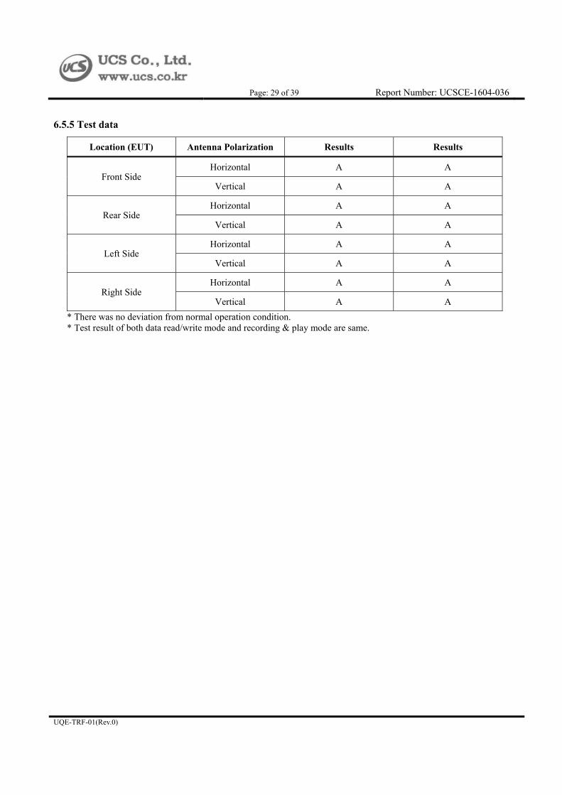
6.5.5 Test data
Location (EUT) Antenna Polarization Results Results
Front Side Horizontal A A
Vertical A A
Rear Side Horizontal A A
Vertical A A
Left Side Horizontal A A
Vertical A A
Right Side Horizontal A A
Vertical A A
* There was no deviation from normal operation condition. * Test result of both data read/write mode and recording & play mode are same.

Page: 30 of 39 Report Number: UCSCE-1604-036
UQE-TRF-01(Rev.0)
6.6 Electric fast transient/burst immunity
Test Standard EN 61000-4-4:2012, Criteria: B
Coupling Mains port - Coupling Decoupling Network
Test Level AC Mains: ± 1 kV Peak
Repetition Freq. 5 kHz, Tr / Th = 5 / 50 ns
Coupling Time 60 s
Tested Date 2016.03.28
Input Ratings 230 V~, 50 Hz
Temperature (21.9 ± 0.1) °C Humidity (29.4 ± 0.1) % R.H.
Atmospheric pressure 102.0 kPa
Test Result Met criterion A / Pass
6.6.1 Test set-up and procedure
A ground reference plane was located on the floor. EFT generator was connected to reference ground plane via low impedance connection. For floor standing equipment, EUT was placed on a 0.1 m wooden table. For tabletop equipment, EUT was placed on a 0.1 m above the ground reference plane. Test generator and coupling/decoupling network was placed on, and bounded to, the ground reference plane. When using the coupling clamp, the minimum distance between the coupling plates and all other conductive surfaces, except the ground reference plane beneath the coupling clamp, Shall be 0.5 m.
6.6.2 Measurement uncertainty
It has been demonstrated that the EFT/Burst generator meets the specified requirements in the standard with at least a 95 % confidence.
6.6.3 Test equipment used
Equipment Model Serial No. Vendor Next Cal. Date Use
EMC IMMUNITY TEST
EMCPRO PLUS 0906221 ThermoFisher
Scientific 2016.08.28
Capacitive Clamp CCL 0904227 ThermoFisher
Scientific 2016.08.04
COMPACT IMMUNITY TEST
SYSTEM AXOS5 180998
HAEFELY EMC TECHNOLOGY
2017.02.04
THREE PHASES EXTERNAL CDN
FP-COMB32 181211 HAEFELY EMC TECHNOLOGY
2017.02.04
Capacitive Coupling Clamp
IP4B 181514 HAEFELY EMC TECHNOLOGY
2017.02.04

Page: 31 of 39 Report Number: UCSCE-1604-036
UQE-TRF-01(Rev.0)
6.6.4 Test set-up photos
[Data Read/Write mode]
6.6.5 Test data
EFT Coupling Point Level (±) Criteria Results
L 1 kV B A
N 1 kV B A
PE 1 kV B A
L - N 1 kV B A
L - PE 1 kV B A
N - PE 1 kV B A
L - N - PE 1 kV B A
* There was no deviation from normal operation condition. (data read/write mode) * The EUT is not intended to be used with cables longer than 3 m according to the manufacturer’s specification.

Page: 32 of 39 Report Number: UCSCE-1604-036
UQE-TRF-01(Rev.0)
6.7 Surge immunity
Test Standard EN 61000-4-5:2014, Criteria: B
Coupling Coupling Decoupling Network
Test Level AC Mains (Line to Line): ± 0.5 kV, ± 1 kV
(Line to Earth): ± 0.5 kV, ± 1 kV, ± 2 kV
Number of surge/time 1 time / 30 s, total 5 times
Tested Date 2016.03.28
Input Ratings 230 V~, 50 Hz
Temperature (22.7 ± 0.7) °C Humidity (29.0 ± 0.3) % R.H.
Atmospheric pressure (101.95 ± 0.05) kPa
Test Result Met criterion A / Pass
6.7.1 Test set-up and procedure
A ground reference plane was located on the floor. SURGE generator was connected to reference ground plane via low
impedance connection. For floor standing equipment, EUT was placed on a 0.1 m wooden table.
For tabletop equipment, EUT was placed on a wooden table (0.1 m) above the reference plane.
6.7.2 Measurement uncertainty
It has been demonstrated that the surge tester meets the specified requirements in the standard with at least a 95 %
confidence.
6.7.3 Test equipment used
Equipment Model Serial No. Vendor Next Cal. Date Use
EMC IMMUNITY TEST
EMCPRO PLUS 0906221 ThermoFisher
Scientific 2016.08.28
I/O Lin Coupler/Decoupler
CM-I/OCD 0906226 ThermoFisher
Scientific -
Telecom coupler/Decoupler
CM-TELCD 0905226 ThermoFisher
Scientific -
COMPACT IMMUNITY TEST
SYSTEM AXOS5 180998
HAEFELY EMC TECHNOLOGY
2017.02.04
THREE PHASES EXTERNAL CDN
FP-COMB32 181211 HAEFELY EMC TECHNOLOGY
2017.02.04

Page: 33 of 39 Report Number: UCSCE-1604-036
UQE-TRF-01(Rev.0)
6.7.4 Test set-up photos
[Data Read/Write mode]
6.7.5 Test data
Coupling Point Level (±) Criteria Results
L to N 0.5 kV, 1 kV B A
L to PE 0.5 kV, 1 kV, 2 kV B A
N to PE 0.5 kV, 1 kV, 2 kV B A
* There was no deviation from normal operation condition. (data read/write mode) * The EUT does not have the ports that may connect directly to outdoor cables.

Page: 34 of 39 Report Number: UCSCE-1604-036
UQE-TRF-01(Rev.0)
6.8 Conducted disturbance induced by RF fields immunity
Test Standard EN 61000-4-6:2014, Criteria: A
Tested Frequency 150 kHz ~ 80 MHz
Test Level/Modulation 3 V (AM 80 %, 1 kHz)
Coupling Method AC Mains: M3
Dwell Time 1 s
Step Size log 1 % step
Tested Date 2016.03.28
Input Ratings 230 V~, 50 Hz
Temperature (23.8 ± 0.1) °C Humidity (26.55 ± 0.05) % R.H.
Atmospheric pressure 101.9 kPa
Test Result Met criterion A / Pass
6.8.1 Test set-up and procedure A ground reference plane was located on the floor. The test was performed on a ground reference plane on a 0.1 m wooden table. This test were performed using CDN for mains, clamp for signal and injection probe. The frequency range was swept from 150 kHz to 80 MHz. This frequency range was modulated with 1 kHz sine wave at 80 %. The signal generators provided the modulated frequency at a 1 % step size. The power and all network cable, I/O cables longer than 3 m length were tested.
6.8.2 Measurement uncertainty
The measurement uncertainty is 2.3 dB The measurement uncertainty is given with a confidence of 95 % with the coverage factor, k = 2.
6.8.3 Test equipment used
Equipment Model Serial No. Vendor Next Cal. Date Use
CDN M2 FCC-801-M2-16A 091165 FCC 2016.08.04
CDN M3 FCC-801-M3-16A 091994 FCC 2016.08.04
EM INJECTION CLAMP
F-203I-23mm 091199 FCC 2016.08.04
Continuous Wave Simulator
CWS 500N1 P1247105423 EM Test 2017.02.04
Coaxial Fixed Attenuator
ATT6/75 P1306112966 EM Test 2017.02.04

Page: 35 of 39 Report Number: UCSCE-1604-036
UQE-TRF-01(Rev.0)
6.8.4 Test set-up photos
[Data Read/Write mode]
6.8.5 Test data
Coupling Point Coupling Method Criteria Results
AC Mains CDN (M3) A A
* There was no deviation from normal operation condition. (data read/write mode) * The EUT is not intended to be used with cables longer than 3 m according to the manufacturer’s specification.

Page: 36 of 39 Report Number: UCSCE-1604-036
UQE-TRF-01(Rev.0)
7. EUT Photos
7.1 External view
[Front view]
[Rear view]

Page: 37 of 39 Report Number: UCSCE-1604-036
UQE-TRF-01(Rev.0)
7.2 Internal view

Page: 38 of 39 Report Number: UCSCE-1604-036
UQE-TRF-01(Rev.0)
7.3 Internal board view

Page: 39 of 39 Report Number: UCSCE-1604-036
UQE-TRF-01(Rev.0)