Embed Size (px)
Citation preview
Emergency Response Guide
Hyundai Sonata Hybrid
Table of Contents
Introduction . . . . . . . . . . . . . . . . . . . . . . . . . . . . . . . . . . . . . . . . . . . . . . . . . . . . . . . . . . . . . . . . . . 1
Sonata Hybrid Identification . . . . . . . . . . . . . . . . . . . . . . . . . . . . . . . . . . . . . . . . . . . . . . . . . . . . . 2
General Vehicle Description . . . . . . . . . . . . . . . . . . . . . . . . . . . . . . . . . . . . . . . . . . . . . . . . . . . . 2
Exterior Visual Identification . . . . . . . . . . . . . . . . . . . . . . . . . . . . . . . . . . . . . . . . . . . . . . . . . . 2
Interior Visual Identification . . . . . . . . . . . . . . . . . . . . . . . . . . . . . . . . . . . . . . . . . . . . . . . . . . . 6
Vehicle Systems Overview . . . . . . . . . . . . . . . . . . . . . . . . . . . . . . . . . . . . . . . . . . . . . . . . . . . . . . . 8
Key Specifications . . . . . . . . . . . . . . . . . . . . . . . . . . . . . . . . . . . . . . . . . . . . . . . . . . . . . . . . . . . 8
Vehicle Component Locations . . . . . . . . . . . . . . . . . . . . . . . . . . . . . . . . . . . . . . . . . . . . . . . . . 8
Vehicle Components . . . . . . . . . . . . . . . . . . . . . . . . . . . . . . . . . . . . . . . . . . . . . . . . . . . . . . . . . 9
Hybrid System Operation . . . . . . . . . . . . . . . . . . . . . . . . . . . . . . . . . . . . . . . . . . . . . . . . . . . . . . 11
Operating Parameters . . . . . . . . . . . . . . . . . . . . . . . . . . . . . . . . . . . . . . . . . . . . . . . . . . . . . . . 11
High-Voltage Electrical Isolation . . . . . . . . . . . . . . . . . . . . . . . . . . . . . . . . . . . . . . . . . . . . . . . . 12
Regulation of High-Voltage Electrical Current . . . . . . . . . . . . . . . . . . . . . . . . . . . . . . . . . . . . . 12
High-Voltage Safety System . . . . . . . . . . . . . . . . . . . . . . . . . . . . . . . . . . . . . . . . . . . . . . . . . . . 12
Supplemental Restraint System (SRS) . . . . . . . . . . . . . . . . . . . . . . . . . . . . . . . . . . . . . . . . . . . . 13
Emergency Response Procedures . . . . . . . . . . . . . . . . . . . . . . . . . . . . . . . . . . . . . . . . . . . . . . . . . 15
Initial Response . . . . . . . . . . . . . . . . . . . . . . . . . . . . . . . . . . . . . . . . . . . . . . . . . . . . . . . . . . . . . . 15
Identify . . . . . . . . . . . . . . . . . . . . . . . . . . . . . . . . . . . . . . . . . . . . . . . . . . . . . . . . . . . . . . . . . . . 15
Immobilize . . . . . . . . . . . . . . . . . . . . . . . . . . . . . . . . . . . . . . . . . . . . . . . . . . . . . . . . . . . . . . . . 16
Disable . . . . . . . . . . . . . . . . . . . . . . . . . . . . . . . . . . . . . . . . . . . . . . . . . . . . . . . . . . . . . . . . . . . . 17
Extrication . . . . . . . . . . . . . . . . . . . . . . . . . . . . . . . . . . . . . . . . . . . . . . . . . . . . . . . . . . . . . . . . . . 21
Firefighting . . . . . . . . . . . . . . . . . . . . . . . . . . . . . . . . . . . . . . . . . . . . . . . . . . . . . . . . . . . . . . . . . 22
Submersion . . . . . . . . . . . . . . . . . . . . . . . . . . . . . . . . . . . . . . . . . . . . . . . . . . . . . . . . . . . . . . . . . 23
High-Voltage Battery Damage/Spills . . . . . . . . . . . . . . . . . . . . . . . . . . . . . . . . . . . . . . . . . . . . . 24
Mitigation Procedures . . . . . . . . . . . . . . . . . . . . . . . . . . . . . . . . . . . . . . . . . . . . . . . . . . . . . . . 24
First Aid for Electrolyte Exposure . . . . . . . . . . . . . . . . . . . . . . . . . . . . . . . . . . . . . . . . . . . . . . . 25
Towing/Jump Starting . . . . . . . . . . . . . . . . . . . . . . . . . . . . . . . . . . . . . . . . . . . . . . . . . . . . . . . . . . 26
Towing . . . . . . . . . . . . . . . . . . . . . . . . . . . . . . . . . . . . . . . . . . . . . . . . . . . . . . . . . . . . . . . . . . . . . 26
Jump Starting . . . . . . . . . . . . . . . . . . . . . . . . . . . . . . . . . . . . . . . . . . . . . . . . . . . . . . . . . . . . . . . 27
Appendix A . . . . . . . . . . . . . . . . . . . . . . . . . . . . . . . . . . . . . . . . . . . . . . . . . . . . . . . . . . . . . . . . . . . A-1
Appendix B . . . . . . . . . . . . . . . . . . . . . . . . . . . . . . . . . . . . . . . . . . . . . . . . . . . . . . . . . . . . . . . . . . . B-1

Hyundai Sonata Hybrid Page 1
Introduction
Foreword:
Hyundai has high standards and is dedicated to the safety of our customers and emergency responders alike. Hyundai is providing this hybrid vehicle information as a result of our commitment to safety.
Document Purpose:
The purpose of this document is to familiarize emergency responders and the towing/roadside assistance industry with the proper methods to treat the Hyundai Sonata Hybrid in an emergency situation. This guide offers a basic overview of key vehicle systems and provides instructions for dealing with the different types of situations encountered by emergency responders. The emergency response procedures for this vehicle are somewhat similar to a conventional Sonata with additional information provided on dealing with the high-voltage electrical system.
Vehicle Description:
As with other hybrids, the Hyundai Sonata Hybrid uses a conventional gasoline powered internal combustion engine paired with a high-voltage electric motor to propel the vehicle. The high-voltage electrical system is completely self-contained and does not need to be recharged by an external power source such as a charging station. The high-voltage battery is recharged while the vehicle is being driven. This is accomplished through the use of a generator that produces electricity during driving and braking.

Hyundai Sonata Hybrid Page 2
Sonata Hybrid Identification
General Vehicle Description:
The Hyundai Sonata Hybrid is built on a conventional Sonata chassis and therefore the four door sedan looks very similar to its conventional counterpart. The best approach is to assume that all Sonatas are Hybrids until proven otherwise. Using the information provided in this section, responders will be able to differentiate between the two.
Exterior Visual Identification:
Badging or Symbols
The Sonata Hybrid can be identified by unique badging found on the exterior of the vehicle. On the front of the vehicle is the Hyundai logo, a slanted, stylized 'H' with a blue background, there is a blue drive badge on each of the front fenders, and on the passenger side of the trunk lid there is a hybrid badge. Badging may become hidden after a crash due to damage to the vehicle. Always be sure to inspect all sides of the vehicle before determining whether or not a badge is present.
NOTE BLUE BACKGROUND
Hyundai Sonata Hybrid Page 3
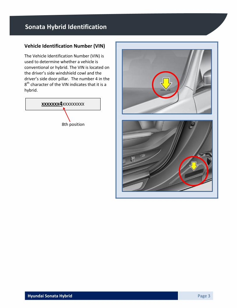
Sonata Hybrid Identification Vehicle Identification Number (VIN)
The Vehicle Identification Number (VIN) is used to determine whether a vehicle is conventional or hybrid. The VIN is located on the driver’s side windshield cowl and the driver’s side door pillar. The number 4 in the 8th character of the VIN indicates that it is a hybrid. 8th position
XXXXXXX4XXXXXXXXX

Hyundai Sonata Hybrid Page 4
Sonata Hybrid Identification
Engine Compartment
Unlike the conventionally powered Sonata, the Hybrid version has a plastic engine cover with “hybrid” clearly shown on it.
Additionally, there are orange colored high-voltage electrical cables in the engine compartment.

Hyundai Sonata Hybrid Page 5
Sonata Hybrid Identification Vehicle Underside
An orange colored cable is also visible on the underside of the vehicle. This cable runs along the passenger side from the rear of the vehicle to the engine compartment.
xx Other Notable Features
Unlike the conventional Sonata, the Hybrid has an Active Air Flap behind the front bumper. This large black frontal area distinguishes the Hybrid from its conventional counterpart.
FRONT
REAR
Hyundai Sonata Hybrid Page 6
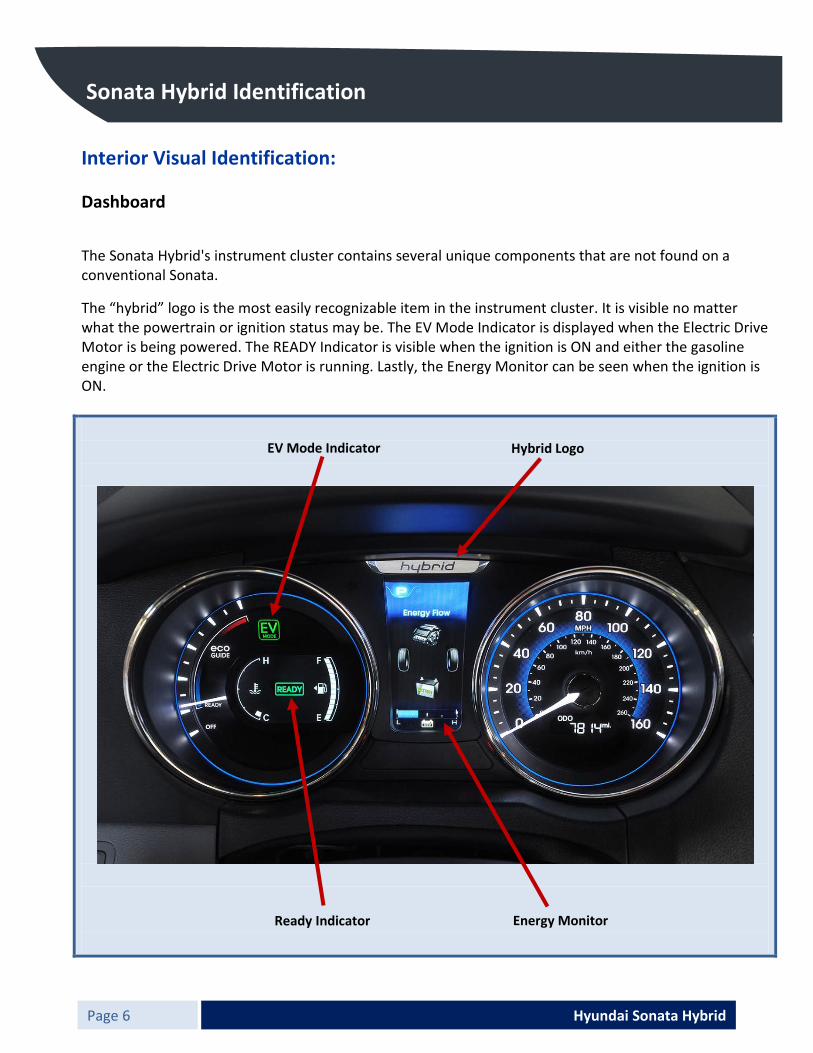
Sonata Hybrid Identification Interior Visual Identification: Dashboard
The Sonata Hybrid's instrument cluster contains several unique components that are not found on a conventional Sonata.
The “hybrid” logo is the most easily recognizable item in the instrument cluster. It is visible no matter what the powertrain or ignition status may be. The EV Mode Indicator is displayed when the Electric Drive Motor is being powered. The READY Indicator is visible when the ignition is ON and either the gasoline engine or the Electric Drive Motor is running. Lastly, the Energy Monitor can be seen when the ignition is ON.
EV Mode Indicator Hybrid Logo
Ready Indicator Energy Monitor

Hyundai Sonata Hybrid Page 7
Sonata Hybrid Identification
High-Voltage Battery Vents
The battery venting is located inside the trunk. Ambient air is drawn into the battery pack through an inlet on the top side of the pack. The duct’s inlet is on the rear package tray, which is visible through the rear window. Air is pushed out through a duct that exits to the exterior through a vent in the left rear wheelwell opening. This vent is not easily seen or accessible to emergency responders.

Hyundai Sonata Hybrid Page 8
Vehicle Systems Overview
Key Specifications:
Curb Weight: 3578 pounds Gasoline Engine: 166 hp - 2.4L Hybrid Engine Fuel Tank: 17.2 US gallons Electric Drive Motor: 34 Kw - 40 hp HV Battery: Lithium-ion polymer (LiPB) 270 Volt Transmission: Automatic Seating Capacity: 5
Vehicle Component Locations:
12V Auxiliary Battery High-Voltage Cable
Hybrid Starter Generator (HSG)
High-Voltage Battery Assembly
Hybrid Power Control Unit
Electric Drive Motor
Electric AC Compressor
Fuel Line
Fuel Tank
Hyundai Sonata Hybrid Page 9
Vehicle Systems Overview
Vehicle Components:
The following components can be found in all Sonata Hybrid vehicles.
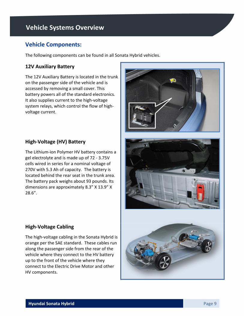
12V Auxiliary Battery
The 12V Auxiliary Battery is located in the trunk on the passenger side of the vehicle and is accessed by removing a small cover. This battery powers all of the standard electronics. It also supplies current to the high-voltage system relays, which control the flow of high-voltage current.
High-Voltage (HV) Battery
The Lithium-ion Polymer HV battery contains a gel electrolyte and is made up of 72 - 3.75V cells wired in series for a nominal voltage of 270V with 5.3 Ah of capacity. The battery is located behind the rear seat in the trunk area. The battery pack weighs about 93 pounds. Its dimensions are approximately 8.3” X 13.9” X 28.6”.
High-Voltage Cabling
The high-voltage cabling in the Sonata Hybrid is orange per the SAE standard. These cables run along the passenger side from the rear of the vehicle where they connect to the HV battery up to the front of the vehicle where they connect to the Electric Drive Motor and other HV components.
Hyundai Sonata Hybrid Page 10
Vehicle Systems Overview
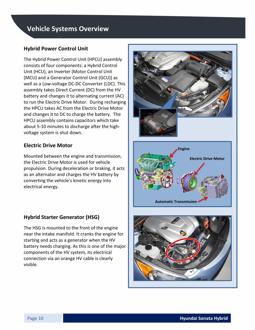
Hybrid Power Control Unit
The Hybrid Power Control Unit (HPCU) assembly consists of four components: a Hybrid Control Unit (HCU), an Inverter (Motor Control Unit (MCU) and a Generator Control Unit (GCU)) as well as a Low-voltage DC-DC Converter (LDC). This assembly takes Direct Current (DC) from the HV battery and changes it to alternating current (AC) to run the Electric Drive Motor. During recharging the HPCU takes AC from the Electric Drive Motor and changes it to DC to charge the battery. The HPCU assembly contains capacitors which take about 5-10 minutes to discharge after the high-voltage system is shut down.
Electric Drive Motor
Mounted between the engine and transmission, the Electric Drive Motor is used for vehicle propulsion. During deceleration or braking, it acts as an alternator and charges the HV battery by converting the vehicle’s kinetic energy into electrical energy.
Hybrid Starter Generator (HSG)
The HSG is mounted to the front of the engine near the intake manifold. It cranks the engine for starting and acts as a generator when the HV battery needs charging. As this is one of the major components of the HV system, its electrical connection via an orange HV cable is clearly visible.
Engine
Electric Drive Motor
Automatic Transmission
Hyundai Sonata Hybrid Page 11
Vehicle Systems Overview
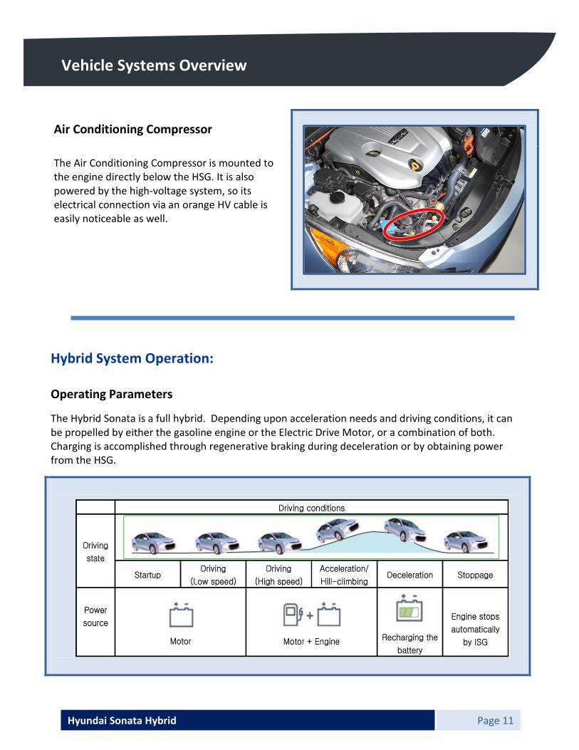
Air Conditioning Compressor
The Air Conditioning Compressor is mounted to the engine directly below the HSG. It is also powered by the high-voltage system, so its electrical connection via an orange HV cable is easily noticeable as well.
2.
Hybrid System Operation: Operating Parameters
The Hybrid Sonata is a full hybrid. Depending upon acceleration needs and driving conditions, it can be propelled by either the gasoline engine or the Electric Drive Motor, or a combination of both. Charging is accomplished through regenerative braking during deceleration or by obtaining power from the HSG.

Hyundai Sonata Hybrid Page 12
Vehicle Systems Overview
High-Voltage Electrical Isolation:
Unlike the 12V electrical system that is grounded to the vehicle’s chassis, the Sonata Hybrid’s high-voltage electrical system is designed to be isolated from the vehicle.
Regulation of High-Voltage Electrical Current:
Current from the High-Voltage Battery is controlled by the Power Relay Assembly (PRA), which consists of Positive and Negative Main Relays, a Pre-charge Relay, Pre-charge Resistor, and the Battery Current Sensor. The PRA is located inside the High-Voltage Battery Pack Assembly and controls the high-voltage power circuit between the High-Voltage Battery and the Hybrid Power Control Unit.
High-Voltage Safety System:
There are multiple safety systems incorporated into the Sonata Hybrid. The system that protects the High-Voltage Electrical System is called the Battery Management System (BMS). The BMS is located inside the High-Voltage Battery Assembly and measures several parameters to maintain the optimal performance of the High-Voltage Battery. It controls the battery cooling fan to ensure proper battery operation. In addition, if a system fault occurs, the BMS turns off the PRA to protect the system.
PRA
BMS
Shown with back Seat Removed
Shown with back Seat Removed

Hyundai Sonata Hybrid Page 13
Vehicle Systems Overview
Supplemental Restraint System (SRS): Airbags
The Sonata Hybrid is equipped with a total of six airbags for passenger protection. These airbags are located in standard areas of the vehicle where emergency responders are accustomed to finding them. Care should always be taken to secure any 12V power sources in the vehicle before extrication operations are initiated or emergency response personnel enter the vehicle. This is critical in order to prevent any accidental deployment of the supplemental restraints.
Airbag Types and Locations
Type Location Frontal Driver Side Frontal Passenger Side Side Impact Thorax Driver Side Side Impact Thorax Passenger Side Side Impact Curtain Driver Side Side Impact Curtain Passenger Side
Side Impact Curtain
Side Impact Thorax
Driver’s Frontal
Side Impact Thorax
Passenger Frontal

Hyundai Sonata Hybrid Page 14
Vehicle Systems Overview
Seatbelt Pretensioners
The Sonata Hybrid has a total of four seatbelt pretensioners. Two are located in the Driver’s Side B-pillar, one is a Belt Pretensioner (BPT) and the other is an Anchor Pretensioner (APT). The other two are located in the Passenger’s Side B-pillar. They also consist of a BPT and an APT.
Sensor and Control Module Locations
The airbags and pretensioners are managed by the SRS Control Module, or SRSCM, which is located below the front of the center console. In addition, there are four side impact sensors: two conventional accelerometer sensors in the B-pillars, and two pressure sensing sensors inside of the front door modules. Their locations are illustrated in the image below.
SRS Component Locations
1. Driver Airbag (DAB) 2. Steering Wheel 3. Clock Spring 4. Seat Belt Pretensioner (BPT) 5. Pressure Side Impact Sensor (P-SIS) 6. Side Impact Sensor (SIS) 7. Side Airbag (SAB) 8. Passenger Airbag (PAB) 9. Front Impact Sensor (FIS) 10. Curtain Airbag (CAB) 11. Supplemental Restraint System Control Module (SRSCM) 12. Airbag Warning Lamp 13. Telltale Lamp 14. Weight Classification System (WCS) Module 15. Anchor Pretensioner (APT) 16. Seat Track Position Sensor (STPS)
WARNING! x Unintentional deployment of SRS components can result in serious injury
or death. Do not cut through any SRS component. x SRS components can remain powered and active for up to 3 minutes after
the 12V electrical system is shut off or disabled.

Hyundai Sonata Hybrid Page 15
Emergency Response Procedures
Initial Response:
The following procedures should be utilized when working with a Sonata Hybrid at an emergency scene. All other operations should be consistent with your department’s SOPs or SOGs.
Identify
When working with a Sonata at an accident scene, emergency responders should always assume that it is a hybrid model until it can be proven otherwise using the identification features outlined at the beginning of this Emergency Response Guide (ERG). External badging will usually be the first indicator, but it often can be hidden by damage caused in a crash. Responders must always be sure to inspect all sides of the vehicle, as well as using the identifiers found under the hood and in the interior of the vehicle.
Hyundai Sonata Hybrid Page 16
Emergency Response Procedures
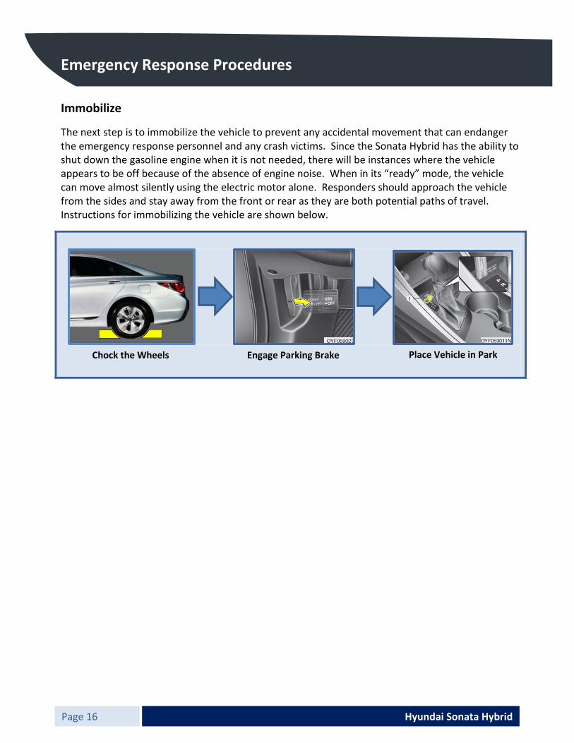
Immobilize
The next step is to immobilize the vehicle to prevent any accidental movement that can endanger the emergency response personnel and any crash victims. Since the Sonata Hybrid has the ability to shut down the gasoline engine when it is not needed, there will be instances where the vehicle appears to be off because of the absence of engine noise. When in its “ready” mode, the vehicle can move almost silently using the electric motor alone. Responders should approach the vehicle from the sides and stay away from the front or rear as they are both potential paths of travel. Instructions for immobilizing the vehicle are shown below.
Chock the Wheels Engage Parking Brake Place Vehicle in Park

Hyundai Sonata Hybrid Page 17
Emergency Response Procedures
Disable
After the vehicle has been secured to prevent movement, the final step in the initial response process is to disable the vehicle, its SRS components, and its high-voltage electrical system. This can be accomplished in one of two ways:
Primary Method: Turn the vehicle off, disconnect the 12V Auxiliary Battery, and remove the Service Disconnect Plug.
1. Determine if the vehicle is on or off by looking at the indicators on the instrument cluster (see page 6).
a. If the vehicle is off move to step #2. b. If the instrument cluster lights indicate
the vehicle is on push the “Engine START/STOP” power button located at the right of the steering column according to the conditions in the tables below.
Brake Pedal Not Applied
Press Engine START/STOP Button
LED Color on Engine START/STOP Button
State of Vehicle
- OFF OFF 1st time AMBER ACCESSORY 2nd time BLUE ON 3rd time OFF OFF
Brake Pedal Applied and Transmission in Park Press Engine
START/STOP Button LED Color on Engine START/STOP Button
State of Vehicle
- OFF OFF 1st time BLUE START
Hyundai Sonata Hybrid Page 18
Emergency Response Procedures
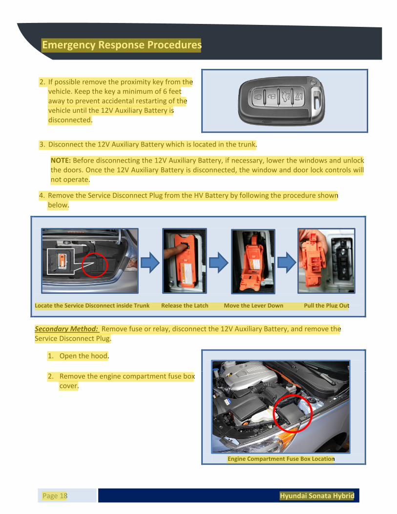
2. If possible remove the proximity key from the vehicle. Keep the key a minimum of 6 feet away to prevent accidental restarting of the vehicle until the 12V Auxiliary Battery is disconnected.
3. Disconnect the 12V Auxiliary Battery which is located in the trunk.
NOTE: Before disconnecting the 12V Auxiliary Battery, if necessary, lower the windows and unlock the doors. Once the 12V Auxiliary Battery is disconnected, the window and door lock controls will not operate.
4. Remove the Service Disconnect Plug from the HV Battery by following the procedure shown below.
Secondary Method: Remove fuse or relay, disconnect the 12V Auxiliary Battery, and remove the Service Disconnect Plug.
1. Open the hood.
2. Remove the engine compartment fuse box cover.
Locate the Service Disconnect inside Trunk Release the Latch Move the Lever Down Pull the Plug Out
Engine Compartment Fuse Box Location

Hyundai Sonata Hybrid Page 19
Emergency Response Procedures
3. Remove the IG1 relay (tan). Refer to the illustration for relay location. If the correct relay cannot be recognized, pull all of the fuses and relays from the fuse box.
4. Disconnect the 12V Auxiliary Battery, which is located in the trunk.
NOTE: Before disconnecting the 12V Auxiliary Battery, if necessary, lower the windows and unlock the doors. Once the 12V Auxiliary Battery is disconnected, the window and door lock controls will not operate.
5. Complete the steps shown below to remove the Service Disconnect Plug from the HV Battery.
Engine Compartment Fuse Box
Locate the Service Disconnect inside Trunk Release the Latch Move the Lever Down Pull the Plug Out

Hyundai Sonata Hybrid Page 20
Emergency Response Procedures
If neither of the preceding methods can be completed, emergency responders must be aware of the potential for accidental SRS activation as well as understand that there is no guarantee that the high-voltage system has been shut down.
HIGH VOLTAGE!
x Before any type of emergency service is performed on this vehicle the high-voltage system must be shut down. Wait 5-10 minutes after shut down to allow high-voltage capacitors to discharge sufficiently.
x Even after the high-voltage system has been shut down and discharged, all high-voltage components should be treated as if they are still energized.
x Failure to shut down and disable the high-voltage system prior to emergency operations can result in serious injury or death.
EXPLOSIVE!
ͻ SRS Components can be unintentionally deployed. ͻ To avoid unintentional deployment, the 12V electrical system must be shut
down. Wait 3 minutes after the system is shut down or disabled to allow the voltage to discharge sufficiently. Do not cut through any SRS Component.
ͻ Failure to shut down and disable the SRS system prior to emergency operations or cutting through SRS Components can result in serious injury or death.

Hyundai Sonata Hybrid Page 21
Emergency Response Procedures
Having addressed the general initial response procedures for handling the Sonata Hybrid in an emergency, the following sections will address specific types of emergencies.
Extrication:
Extrication operations for the Sonata Hybrid are almost the same as for a conventional vehicle, but with some notable exceptions. Utilize the Identify, Immobilize, and Disable model described in the previous pages prior to engaging in extrication operations.
Vehicle Stabilization
Use standard stabilization (cribbing) points. Always be sure to connect to a structural member of the vehicle, and avoid placing cribbing under high-voltage cables, fuel lines, and other areas not normally considered acceptable.
Tire Deflation
In some instances responders may determine the need to deflate the tires to stabilize the vehicle. In this case, note that this vehicle uses a Tire Pressure Monitoring System. The sensors in the tires are mounted by means of a metal valve stem. To rapidly deflate the tires it might be necessary to snap off the valve stem with pliers or remove the valve cap and Schrader valve.
Extrication Equipment and Techniques
Standard extrication equipment can be employed on this vehicle, and normal techniques and the dispatching unit’s Standard Operating Procedures (SOPs) and Standard Operating Guidelines (SOGs) should be followed. There are no high-voltage cables or components in areas that are considered standard cut points. Extrication personnel should always visually inspect the area being cut to ensure no SRS or high-voltage components are compromised.
Cribbing Points

Hyundai Sonata Hybrid Page 22
Emergency Response Procedures
Firefighting:
After Initial Emergency Response Procedures have been applied, Firefighting Procedures may begin. Hyundai recommends that each response team follow their own department’s standard operating procedures for fighting vehicle fires in combination with the Sonata Hybrid specific details that are covered in this section.
Firefighting Operations
If the high-voltage battery pack is either involved in or at risk of being involved in a fire in a Sonata Hybrid, strict cautions must be taken while conducting firefighting operations because of the following reasons:
x Lithium-ion Polymer batteries contain gel electrolyte that can vent, ignite, and produce sparks when subjected to temperatures above 300°F.
x May burn rapidly with a flare-burning effect. x A burning battery could release hydrogen fluoride, carbon monoxide, and carbon dioxide
gasses. Use NIOSH/MSHA approved full-face self-contained breathing apparatus (SCBA) with full protective gear.
Even if the high-voltage battery pack is not directly involved in a vehicle fire, approach the vehicle very carefully.
Extinguishers
To extinguish a small high-voltage battery fire, the following techniques can be used: x Dry chemical x COЇ x Large amounts of water x Regular foam
For a large high-voltage battery fire, use these types of extinguishing methods:
x Large amounts of water x Fog x Regular foam
Placing Water on High-voltage Electricity
When approaching a vehicle fire on a Sonata Hybrid, firefighters should not hesitate to extinguish the fire with water. The vehicle’s high-voltage electrical system is well insulated and unlike the 12V electrical system, it is not part of the vehicle’s chassis.

Hyundai Sonata Hybrid Page 23
Emergency Response Procedures
Overhaul Operations
During overhaul operations it is important for responders to remember the dangers that are still present, even after a fire has been extinguished. Just as during a fire, the same dangers exist. They include, but are not limited to:
x Harmful gasses x Reignition of fire x Electrical Burns, Shock, or Electrocution
To protect oneself and others, and to minimize potential risk, responders should use appropriate Personal Protective Equipment (PPE) defined by the department’s SOP’s and ensure the vehicle’s high-voltage electrical system has been disabled. The methods described at the beginning of the Emergency Response Procedures section (page 17) should be followed. Submersion:
Some emergency responses can involve a submerged vehicle. A Sonata Hybrid that is submerged does not have high-voltage potential on the vehicle’s body or framework and is safe to touch, whether it is in water or on land.
Procedure
1. Remove the vehicle from water. 2. Drain the water from the vehicle. 3. Disable the vehicle by using the methods described at the beginning of the Emergency
Response Procedures section (page 17).
NOTE:
Once the vehicle has been removed from the water and drained, the drained water that is surrounding the area will not be energized. This is a benefit of the design of the Sonata Hybrid’s high-voltage electrical system. It is designed to maintain its isolation from the vehicle’s chassis and the surrounding area.

Hyundai Sonata Hybrid Page 24
Emergency Response Procedures High-Voltage Battery Damage/Spills:
The HV Battery assembly is enclosed in a sturdy metal case that is rigidly mounted to structural components of the vehicle. This construction helps prevent damage to the HV Battery assembly even in severe crashes. This section provides emergency responders with information regarding how to mitigate the severity of a damaged HV Battery assembly or gel electrolyte spill, however unlikely that might be.
Mitigation Procedures
For a gel electrolyte spill or leak: x Eliminate all ignition sources (no smoking, flares, sparks, or flames) in the immediate area. x Do not touch or walk through spilled material. x Absorb electrolyte with earth, sand, or other non-combustible material. x Place leaking battery (if removed from a vehicle) and contaminated absorbant material in
metal containers.
HV Battery Manufacturer Contact Information: HL Green Power, Ltd. Sam-dong, Uiwang-si, Gyeonggi-do, 437-815, Korea
Emergency Phone Number: 011-82-31-596-8214
Material Data Safety Sheet (MSDS): In an emergency, refer to the manufacturer’s MSDS.
See Appendix A
For HV Battery Chemical Emergency Spill, Leak, Fire, Exposure, Accident Call CHEMTREC Day or Night Within USA & Canada:
1-800-424-9300
Disposal of Damaged HV Battery Pack: Contact a local authorized Hyundai dealer.
IRRITANT ͻ� Internal components of HV Batteries are irritants and sensitizers.
ͻ� To avoid contact with these irritants and sensitizers wear positive pressure self- contained breathing apparatus (SCBA) and other personal protective equipment (PPE) designed for use with these types of hazards.
ͻ� Failure to wear proper SCBA and PPE can result in serious injury or death

Hyundai Sonata Hybrid Page 25
Emergency Response Procedures First Aid for Electrolyte Exposure
The Sonata Hybrid HV battery pack is a self-contained, sealed unit and poses no electrolyte contamination hazards under normal conditions. It is only under the rare instance of HV battery damage that the gel electrolyte would be exposed and a person could come in contact with it. Follow these guidelines for electrolyte exposure. If a victim has been exposed to electrolyte, complete these steps first:
x Move victim to fresh air. x Apply artificial respiration if victim is not breathing. x Administer oxygen if breathing is difficult. x Remove and isolate contaminated clothing and shoes. x Ensure that other emergency responders are aware of the materials involved and take
precautions to protect themselves. Then treat the victim according to his/her path of exposure:
Absorption Eye Contact: Rinse eyes with water for 15 minutes. Skin Contact: Wash area thoroughly with soap and water.
Inhalation Remove the victim and leave the area immediately to avoid further exposure.
Ingestion
Compel the victim to drink milk or water and induce vomiting.

Hyundai Sonata Hybrid Page 26
Towing and Jump Starting
Towing: The Sonata Hybrid is no different from a conventionally powered gasoline engine vehicle with regard to towing. If emergency towing is necessary, Hyundai recommends having it done by an authorized Hyundai dealer or a professional tow-truck service. Proper lifting and towing procedures are necessary to prevent damage to the vehicle. Because the vehicle has a front wheel drive powertrain, using a flatbed or wheel dollies is recommended, specific towing guidelines are described below.
A. Towing via flatbed is the recommended method for transporting a Sonata Hybrid.
B. If any of the loaded wheels or suspension components are damaged or the vehicle is being towed with the rear wheels off the ground, use a towing dolly under the front wheels.
C. The vehicle can be towed with the front wheels supported by the lifting equipment in most cases that do not involve damage to wheel, tire, or suspension components.
CAUTION!
x Towing with sling-type equipment or with the front wheels on the ground are not correct methods for towing this vehicle.
x To prevent damage to the vehicle always use wheel lift or flatbed equipment.
x Failure to use the proper towing methods will cause damage to the vehicle.

Hyundai Sonata Hybrid Page 27
Towing and Jump Starting
Jump Starting: Jump Starting the Sonata Hybrid is similar to conventional models. Specific methods and warnings are noted below.
1. Open the cover of 12V Auxiliary Battery in the trunk.
2. Make sure the booster battery is 12-volt and that its negative terminal is grounded.
3. If the booster battery is in another vehicle, do not allow the vehicles to touch.
4. Turn off all unnecessary electrical loads.
5. Connect the jumper cables in the exact sequence shown in the illustration. First connect one end of a jumper cable to the positive terminal of the discharged 12V Auxiliary Battery (1), Then connect the other end to the positive terminal on the booster battery (2). Connect one end of the other jumper cable to the negative terminal of the booster battery (3), Next, connect the other end to a solid, stationary, metallic point (such as, the trunk latch striker) away from the 12V Auxiliary Battery (4). Do not allow the jumper cables to contact anything except the correct battery terminals or the correct ground. Do not lean over the battery when making connections.
6. Start the engine of the vehicle with the booster battery and let it run at 2,000 rpm. Then start the engine of the vehicle with the discharged 12V Auxiliary Battery. Turn the ignition to "hybrid ready" and the LDC will recharge the 12V Auxiliary Battery. Note that the gasoline engine may start at any time when the ignition is in the ready position.
WARNING!
ͻ Keep all flames or sparks away from the battery. The battery produces hydrogen gas that can explode if exposed to flame or sparks. If these instructions are not followed exactly, serious personal injury and damage to the vehicle may occur! If you are not sure how to follow this procedure, seek qualified assistance. Automobile batteries contain sulfuric acid, which is poisonous and highly corrosive. When jump starting, wear protective glasses and be careful not to get acid on yourself, your clothing or on the car.
ͻ Do not attempt to jump start the vehicle if the discharged battery is frozen or if the electrolyte level is low; the battery may rupture or explode.
ͻ Never attempt to check the electrolyte level of the battery as this may cause the battery to rupture or explode causing serious injury.

HL Green Power MATERIAL SAFETY DATA SHEET
MATERIAL SAFETY DATA SHEET
Model YF&TF Battery Module Assembly
1. Chemical Product and Company Identification
Product Identification HL Green Power Battery Module Assembly
Manufacturer HL Green Power. Ltd. Sam-dong, Uiwang-si, Gyeonggi-do, 437-815, Korea
Emergency Telephone Number
82-31-596-8214
2. Composition Information a. Cell
Composition Ingredients % CAS Number Aluminum Foil 2-10 7429-90-5 Metal Oxide (propietary) 20-50 Polyvinylidene Fluoride (PVDF) <5 24937-79-9 Copper Foil 5-20 7440-50-8 Carbon (proprietary) 10-30 7440-44-0 Styrene Butadiene Rubber (SBR) <5 9003-55-8 CarboxyMethyl Cellulose (CMC) <5 Electrolyte (proprietary) 10-30 Aluminum, Copper plate and inert materials Remainder N/A
MSDS Page 1 of 8 Printed 10-11-4
������ƉƉĞŶĚŝdž��
Appendix Page A-1

HL Green Power MATERIAL SAFETY DATA SHEET
b. Base Plate, Pack Cover etc. Composition Ingredients % CAS Number
Iron 99.66 7439-89-6 Manganese 0.19 7439-96-5 Carbon 0.03 7440-44-0 Ethylene-vinyl acetate copolymer 0.02 24937-78-8 SI 0.01 - Phosphorus 0.01 7723-14-0 Sulphur 0.0077 7704-34-9 2-Ethylhexyl acrylate 0.005 103-11-7 Ethyl-acetate 0.005 141-78-6 Silicon 0.005 7440-21-3
c. Cell Module housing etc. Composition Ingredients % CAS Number
PA66 40.60 - Talc 24.96 14807-96-6 PA6 17.30 - Polybutylene terephthalate 6.96 26062-94-2 Copper 4.44 7440-50-8 PBT 1.49 - Iron 1.21 7439-89-6 Polypropylene 0.63 9003-07-0 Polyvinylchloride 0.40 9002-86-2
d.Wire Harness etc. Composition Ingredients % CAS Number
Copper 60.56 7440-50-8 PBT 11.64 - Polyvinylchloride 8.51 9002-86-2 1,2-Benzenedicarboxylic acid, di-C8-10-branched alkyl esters, C9-rich 7.09 68515-48-0
Limestone 6.86 1317-65-3 Polyamid 6.6 2.08 32131-17-2 Hexanedioic acid, polymer with hexahydro-2H-azepin-2-one and 1,6-hex... 1.1 24993-04-2
Polypropylene 0.48 9003-07-0 Zinc (metal) 0.17 7440-66-6
MSDS Page 2 of 8 Printed 10-11-4
Appendix Page A-2
HL Green Power MATERIAL SAFETY DATA SHEET
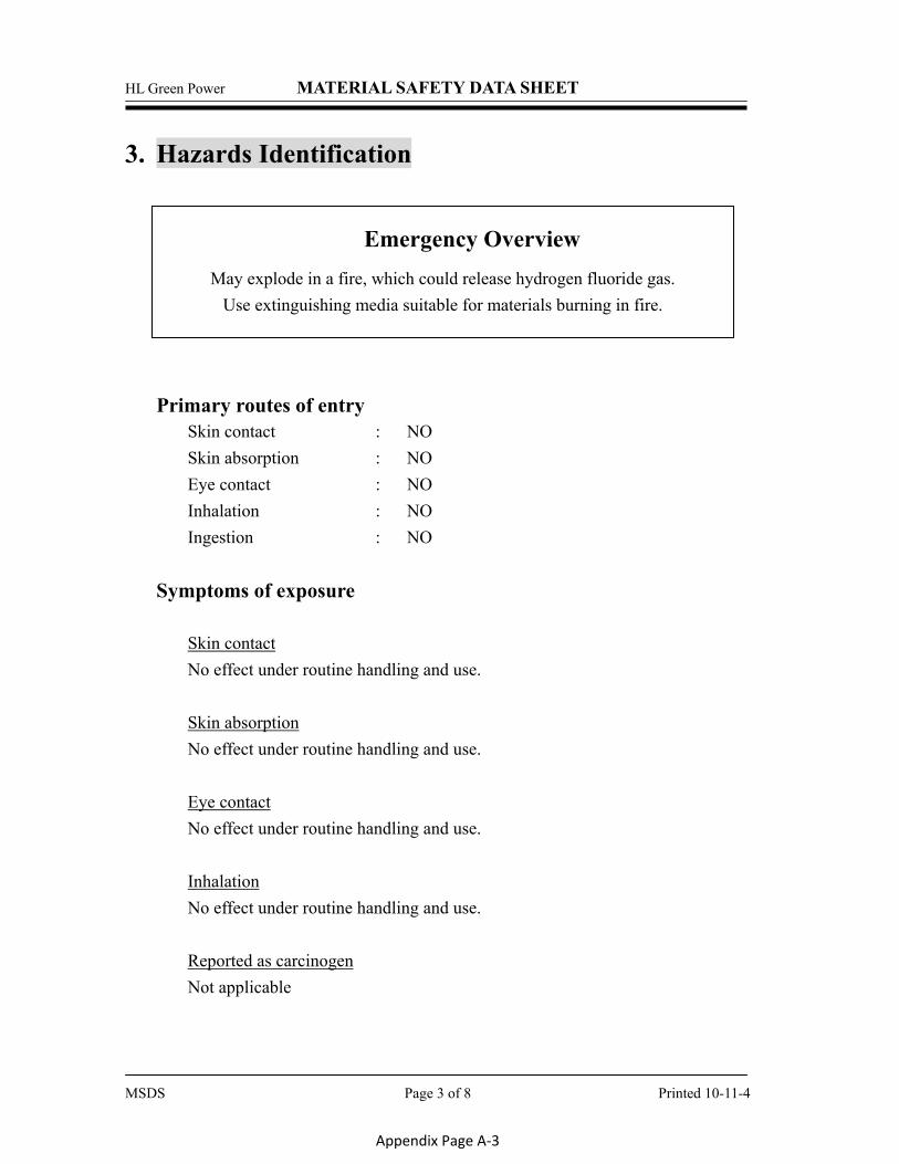
3. Hazards Identification
Emergency Overview May explode in a fire, which could release hydrogen fluoride gas.
Use extinguishing media suitable for materials burning in fire.
Primary routes of entry
Skin contact : NO Skin absorption : NO Eye contact : NO Inhalation : NO Ingestion : NO
Symptoms of exposure
Skin contact No effect under routine handling and use.
Skin absorption No effect under routine handling and use.
Eye contact No effect under routine handling and use.
Inhalation No effect under routine handling and use.
Reported as carcinogen Not applicable
MSDS Page 3 of 8 Printed 10-11-4
Appendix Page A-3
HL Green Power MATERIAL SAFETY DATA SHEET
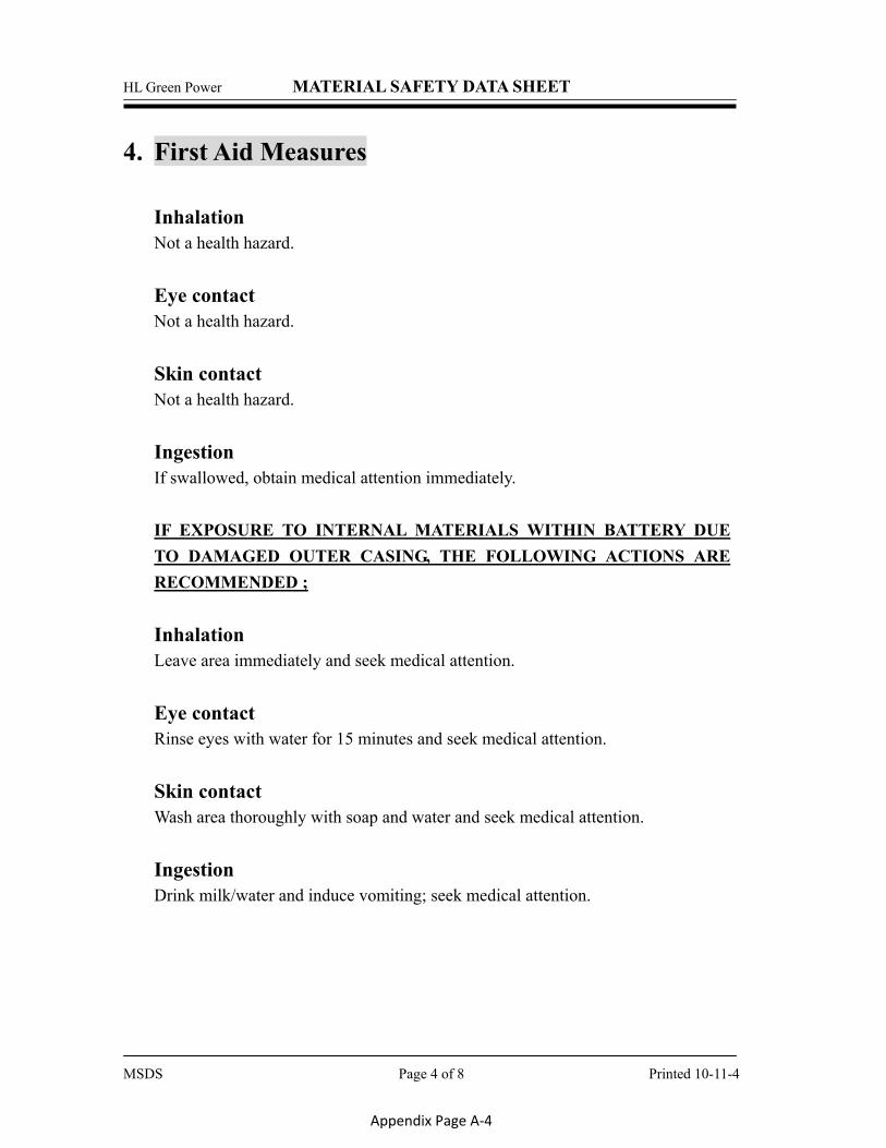
4. First Aid Measures
Inhalation Not a health hazard.
Eye contact Not a health hazard.
Skin contact Not a health hazard.
Ingestion If swallowed, obtain medical attention immediately.
IF EXPOSURE TO INTERNAL MATERIALS WITHIN BATTERY DUE TO DAMAGED OUTER CASING, THE FOLLOWING ACTIONS ARE RECOMMENDED ;
Inhalation Leave area immediately and seek medical attention.
Eye contact Rinse eyes with water for 15 minutes and seek medical attention.
Skin contact Wash area thoroughly with soap and water and seek medical attention.
Ingestion Drink milk/water and induce vomiting; seek medical attention.
MSDS Page 4 of 8 Printed 10-11-4
Appendix Page A-4

HL Green Power MATERIAL SAFETY DATA SHEET
5. Fire Fighting Measures
General Hazard Battery is not flammable but internal organic material will burn if the battery is incinerated. Combustion products include, but are not limited to hydrogen fluoride, carbon monoxide and carbon dioxide. Extinguishing Media Use extinguishing media suitable for the materials that are burning. Special Firefighting Instructions If possible, remove battery from fire fighting area. If heated above 150°C, Battery may explode/vent. Firefighting Equipment Use NIOSH/MSHA approved full-face self-contained breathing apparatus (SCBA) with full protective gear.
6. Accidental Release Measures On Land Place material into suitable containers and call local fire/police department. In Water If possible, remove from water and call local fire/police department.
7. Handling and Storage Handling No special protective clothing required for handling individual batteries. Storage Store in a cool, dry place.
MSDS Page 5 of 8 Printed 10-11-4
Appendix Page A-5
HL Green Power MATERIAL SAFETY DATA SHEET
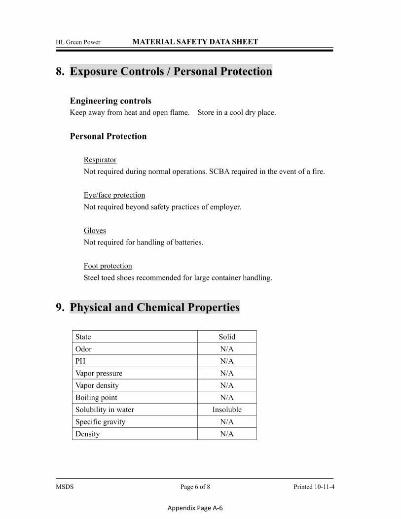
8. Exposure Controls / Personal Protection Engineering controls Keep away from heat and open flame. Store in a cool dry place. Personal Protection
Respirator Not required during normal operations. SCBA required in the event of a fire.
Eye/face protection Not required beyond safety practices of employer.
Gloves Not required for handling of batteries.
Foot protection Steel toed shoes recommended for large container handling.
9. Physical and Chemical Properties
State Solid Odor N/A PH N/A Vapor pressure N/A Vapor density N/A Boiling point N/A Solubility in water Insoluble Specific gravity N/A Density N/A
MSDS Page 6 of 8 Printed 10-11-4
Appendix Page A-6
HL Green Power MATERIAL SAFETY DATA SHEET
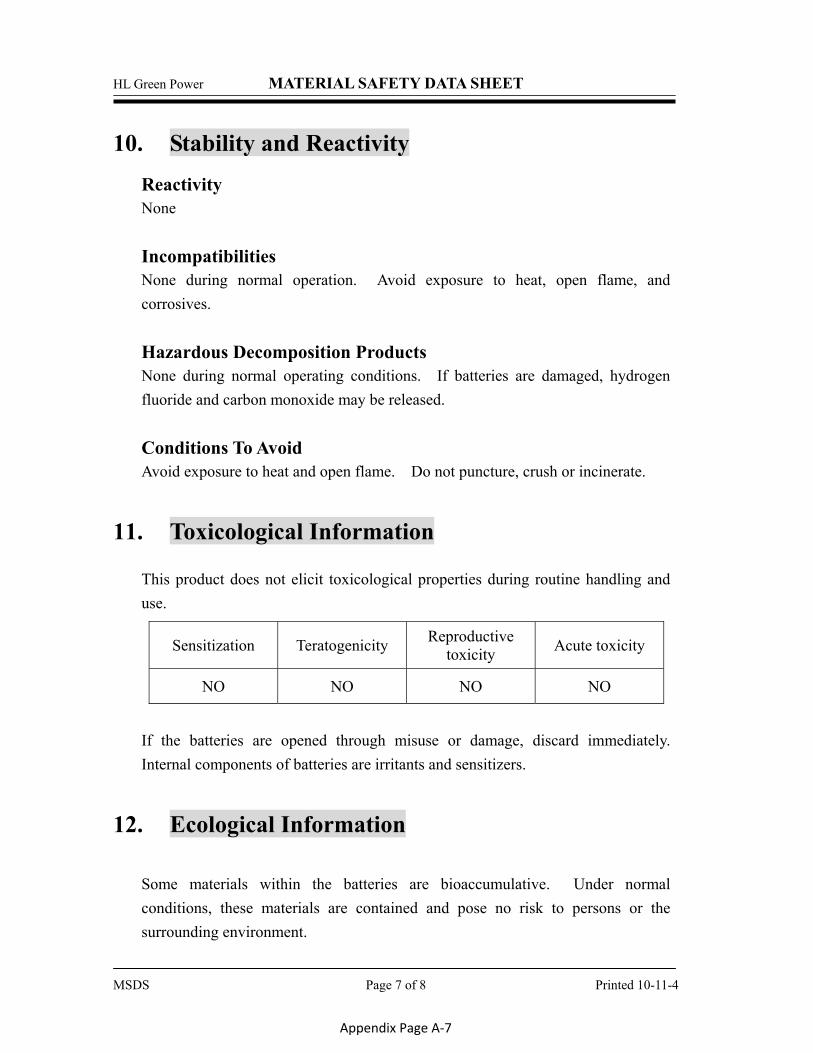
10. Stability and Reactivity Reactivity None Incompatibilities None during normal operation. Avoid exposure to heat, open flame, and corrosives. Hazardous Decomposition Products None during normal operating conditions. If batteries are damaged, hydrogen fluoride and carbon monoxide may be released. Conditions To Avoid Avoid exposure to heat and open flame. Do not puncture, crush or incinerate.
11. Toxicological Information This product does not elicit toxicological properties during routine handling and use.
Sensitization Teratogenicity Reproductive toxicity Acute toxicity
NO NO NO NO
If the batteries are opened through misuse or damage, discard immediately. Internal components of batteries are irritants and sensitizers.
12. Ecological Information Some materials within the batteries are bioaccumulative. Under normal conditions, these materials are contained and pose no risk to persons or the surrounding environment.
MSDS Page 7 of 8 Printed 10-11-4
Appendix Page A-7
HL Green Power MATERIAL SAFETY DATA SHEET
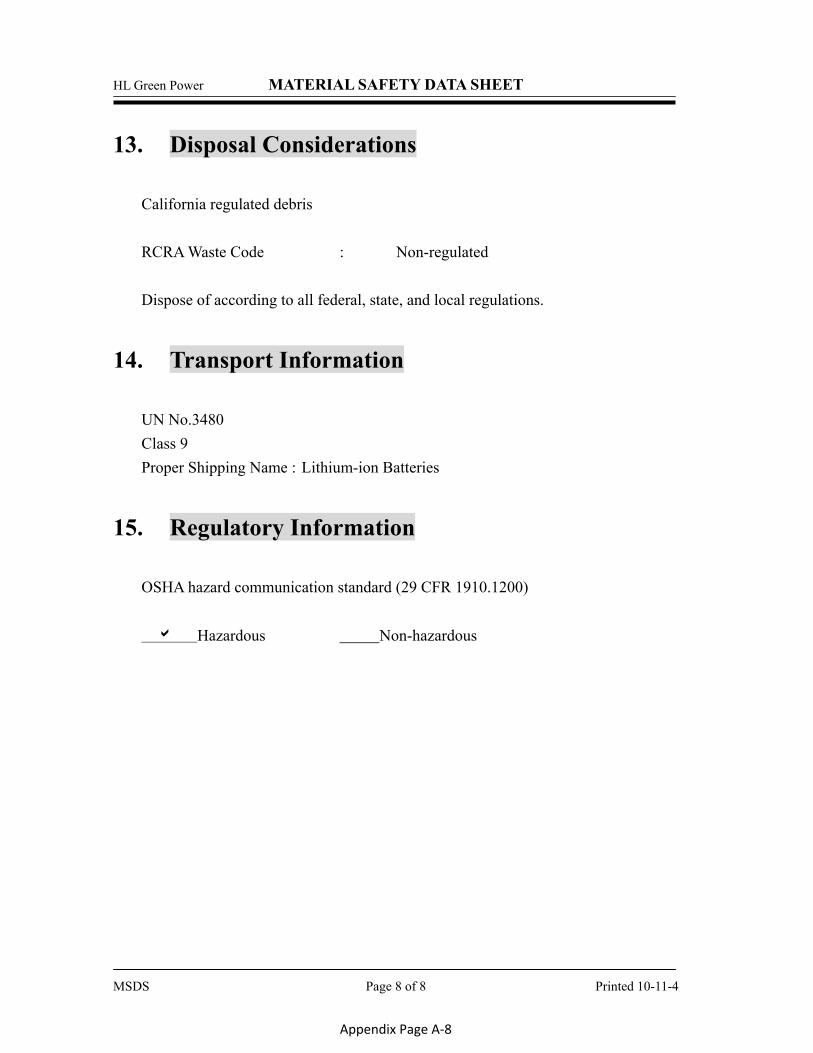
13. Disposal Considerations California regulated debris RCRA Waste Code : Non-regulated Dispose of according to all federal, state, and local regulations.
14. Transport Information UN No.3480 Class 9 Proper Shipping Name :GLithium-ion Batteries
15. Regulatory Information OSHA hazard communication standard (29 CFR 1910.1200) � Hazardous Non-hazardous
MSDS Page 8 of 8 Printed 10-11-4
Appendix Page A-8

This Page Intentionally Left Blank
Hyundai Sonata
Quick Reference Guide
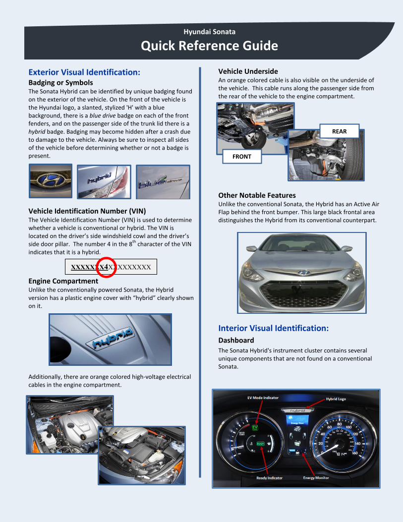
Exterior Visual Identification: Badging or Symbols The Sonata Hybrid can be identified by unique badging found on the exterior of the vehicle. On the front of the vehicle is the Hyundai logo, a slanted, stylized 'H' with a blue background, there is a blue drive badge on each of the front fenders, and on the passenger side of the trunk lid there is a hybrid badge. Badging may become hidden after a crash due to damage to the vehicle. Always be sure to inspect all sides of the vehicle before determining whether or not a badge is present.
Vehicle Identification Number (VIN) The Vehicle Identification Number (VIN) is used to determine whether a vehicle is conventional or hybrid. The VIN is located on the driver’s side windshield cowl and the driver’s side door pillar. The number 4 in the 8th character of the VIN indicates that it is a hybrid.
Engine Compartment Unlike the conventionally powered Sonata, the Hybrid version has a plastic engine cover with “hybrid” clearly shown on it.
Additionally, there are orange colored high-voltage electrical cables in the engine compartment.
Vehicle Underside An orange colored cable is also visible on the underside of the vehicle. This cable runs along the passenger side from the rear of the vehicle to the engine compartment.
Other Notable Features Unlike the conventional Sonata, the Hybrid has an Active Air Flap behind the front bumper. This large black frontal area distinguishes the Hybrid from its conventional counterpart.
Interior Visual Identification: Dashboard The Sonata Hybrid's instrument cluster contains several unique components that are not found on a conventional Sonata.
XXXXXXX4XXXXXXXXX
FRONT
REAR
Hyundai Sonata
Quick Reference Guide
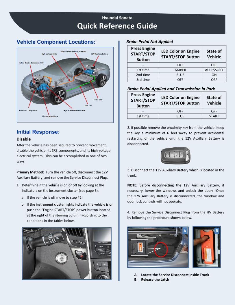
Vehicle Component Locations:
Initial Response: Disable After the vehicle has been secured to prevent movement, disable the vehicle, its SRS components, and its high-voltage electrical system. This can be accomplished in one of two ways: Primary Method: Turn the vehicle off, disconnect the 12V Auxiliary Battery, and remove the Service Disconnect Plug.
1. Determine if the vehicle is on or off by looking at the indicators on the instrument cluster (see page 6).
a. If the vehicle is off move to step #2.
b. If the instrument cluster lights indicate the vehicle is on push the “Engine START/STOP” power button located at the right of the steering column according to the conditions in the tables below.
Brake Pedal Not Applied Press Engine START/STOP
Button
LED Color on Engine START/STOP Button
State of Vehicle
- OFF OFF 1st time AMBER ACCESSORY 2nd time BLUE ON 3rd time OFF OFF
Brake Pedal Applied and Transmission in Park Press Engine START/STOP
Button
LED Color on Engine START/STOP Button
State of Vehicle
- OFF OFF 1st time BLUE START
2. If possible remove the proximity key from the vehicle. Keep the key a minimum of 6 feet away to prevent accidental restarting of the vehicle until the 12V Auxiliary Battery is disconnected.
3. Disconnect the 12V Auxiliary Battery which is located in the trunk.
NOTE: Before disconnecting the 12V Auxiliary Battery, if necessary, lower the windows and unlock the doors. Once the 12V Auxiliary Battery is disconnected, the window and door lock controls will not operate. 4. Remove the Service Disconnect Plug from the HV Battery by following the procedure shown below.
A. Locate the Service Disconnect inside Trunk B. Release the Latch
A B
Hyundai Sonata
Quick Reference Guide
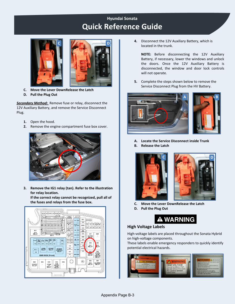
C. Move the Lever DownRelease the Latch D. Pull the Plug Out
Secondary Method: Remove fuse or relay, disconnect the 12V Auxiliary Battery, and remove the Service Disconnect Plug.
1. Open the hood. 2. Remove the engine compartment fuse box cover.
3. Remove the IG1 relay (tan). Refer to the illustration
for relay location. If the correct relay cannot be recognized, pull all of the fuses and relays from the fuse box.
4. Disconnect the 12V Auxiliary Battery, which is located in the trunk.
NOTE: Before disconnecting the 12V Auxiliary Battery, if necessary, lower the windows and unlock the doors. Once the 12V Auxiliary Battery is disconnected, the window and door lock controls will not operate.
5. Complete the steps shown below to remove the Service Disconnect Plug from the HV Battery.
A. Locate the Service Disconnect inside Trunk B. Release the Latch
C. Move the Lever DownRelease the Latch D. Pull the Plug Out
High Voltage Labels
High-voltage labels are placed throughout the Sonata Hybrid on high-voltage components. These labels enable emergency responders to quickly identify potential electrical hazards.
C D
A B
C D
$SSHQGL[�3DJH�%��

© 2011 Hyundai Motor America All rights reserved.
This document may not be altered without the written permission of Hyundai Motor America.
Document No. YFHEV101_REV-0