Embed Size (px)
Citation preview
https://support.industry.siemens.com/cs/ww/de/view/21064024
Application Example 07/2015
Emergency Stop up to SIL 3 / PL e with
a Fail-Safe S7-1500 Controller SIMATIC Safety Integrated
Warranty and Liability
Emergency Stop up to SIL 3 / PL e with a Fail-Safe S7-1500 Controller Entry ID: 21064024, V4.0, 07/2015 2
S
iem
en
s A
G 2
01
5 A
ll ri
gh
ts r
ese
rve
d
Warranty and Liability
Note The application examples are not binding and do not claim to be complete with regard to configuration, equipment or any contingencies. The application examples do not represent customer-specific solutions. They are only intended to provide support for typical applications. You are responsible for the correct operation of the described products. These application examples do not relieve you of the responsibility of safely and professionally using, installing, operating and servicing equipment. When using these Application Examples, you recognize that we cannot be made liable for any damage/claims beyond the liability clause described. We reserve the right to make changes to these Application Examples at any time and without prior notice. If there are any deviations between the recommendations provided in this Application Example and other Siemens publications – e.g. catalogs – the contents of the other documents have priority.
We do not accept any liability for the information contained in this document.
Any claims against us – based on whatever legal reason – resulting from the use of the examples, information, programs, engineering and performance data etc., described in this application example will be excluded. Such an exclusion will not apply in the case of mandatory liability, e.g. under the German Product Liability Act (“Produkthaftungsgesetz”), in case of intent, gross negligence, or injury of life, body or health, guarantee for the quality of a product, fraudulent concealment of a deficiency or breach of a condition which goes to the root of the contract (“wesentliche Vertragspflichten”). The compensation for damages due to a breach of a fundamental contractual obligation is, however, limited to the foreseeable damage, typical for the type of contract, except in the event of intent or gross negligence or injury to life, body or health. The above provisions do not imply a change of the burden of proof to your detriment.
Any form of duplication or distribution of these Application Examples or excerpts hereof is prohibited without the expressed consent of Siemens Industry Sector.
Security informa-
tion
Siemens provides products and solutions with industrial security functions that support the secure operation of plants, solutions, machines, equipment and/or networks. They are important components in a holistic industrial security concept. With this in mind, Siemens’ products and solutions undergo continuous development. Siemens recommends strongly that you regularly check for product updates.
For the secure operation of Siemens products and solutions, it is necessary to take suitable preventive action (e.g. cell protection concept) and integrate each component into a holistic, state-of-the-art industrial security concept. Third-party products that may be in use should also be considered. For more information about industrial security, visit http://www.siemens.com/industrialsecurity.
To stay informed about product updates as they occur, sign up for a product-specific newsletter. For more information, visit https://support.industry.siemens.com.
Table of Contents
Emergency Stop up to SIL 3 / PL e with a Fail-Safe S7-1500 Controller Entry ID: 21064024, V4.0, 07/2015 3
S
iem
en
s A
G 2
01
5 A
ll ri
gh
ts r
ese
rve
d
Table of Contents Warranty and Liability ................................................................................................. 2
1 Task ..................................................................................................................... 4
2 Solution............................................................................................................... 5
2.1 Overview............................................................................................... 5 2.2 Description of the core functionality ..................................................... 6 2.3 Hardware and software components ................................................... 7 2.4 Advantages / customer benefits ........................................................... 8
3 Basics ................................................................................................................. 9
3.1 Basic terms ........................................................................................... 9 3.2 Functional safety .................................................................................. 9 3.3 Emergency stop ................................................................................. 10
4 Mode of Operation ........................................................................................... 12
4.1 Overview............................................................................................. 12 4.2 Standard user program functionality .................................................. 12 4.3 Functionality of the safety program .................................................... 13 4.4 Data exchange between standard user program and safety
program .............................................................................................. 16
5 Configuration and Settings............................................................................. 17
5.1 Configuration of S7-1500 F-CPU ....................................................... 17 5.2 Configuration of the distributed I/O .................................................... 18 5.2.1 Settings of the F-DI ............................................................................ 18 5.2.2 Setting the F-DQ ................................................................................ 20
6 Installation and Commissioning .................................................................... 21
6.1 Installing the hardware ....................................................................... 21 6.2 Commissioning ................................................................................... 21 6.2.1 Preparation ......................................................................................... 21 6.2.2 Loading the S7 project into CPU S7-1516F ....................................... 22 6.2.3 Assigning device names..................................................................... 23 6.2.4 Assigning F-destination address ........................................................ 24
7 Operating the Application ............................................................................... 26
8 Evaluation of the Safety Function .................................................................. 27
8.1 Standards ........................................................................................... 27 8.2 Safety function .................................................................................... 27 8.3 Evaluation according to IEC 62061 .................................................... 28 8.3.1 Evaluation of "Detection" .................................................................... 28 8.3.2 Evaluation of "Evaluation" .................................................................. 29 8.3.3 Evaluation of “Reacting” ..................................................................... 30 8.3.4 Result of the evaluation according to IEC 62061 ............................... 30 8.4 Evaluation according to ISO 13849-1 ................................................ 31 8.4.1 Evaluation of "Detection" .................................................................... 31 8.4.2 Evaluation of "Evaluation" .................................................................. 32 8.4.3 Evaluation of “Reacting” ..................................................................... 33 8.4.4 Result of the evaluation according to ISO 13849-1, ISO 13849-
2 .......................................................................................................... 33
9 Links & Literature ............................................................................................ 34
10 History............................................................................................................... 35
1 Task
Emergency Stop up to SIL 3 / PL e with a Fail-Safe S7-1500 Controller Entry ID: 21064024, V4.0, 07/2015 4
S
iem
en
s A
G 2
01
5 A
ll ri
gh
ts r
ese
rve
d
1 Task
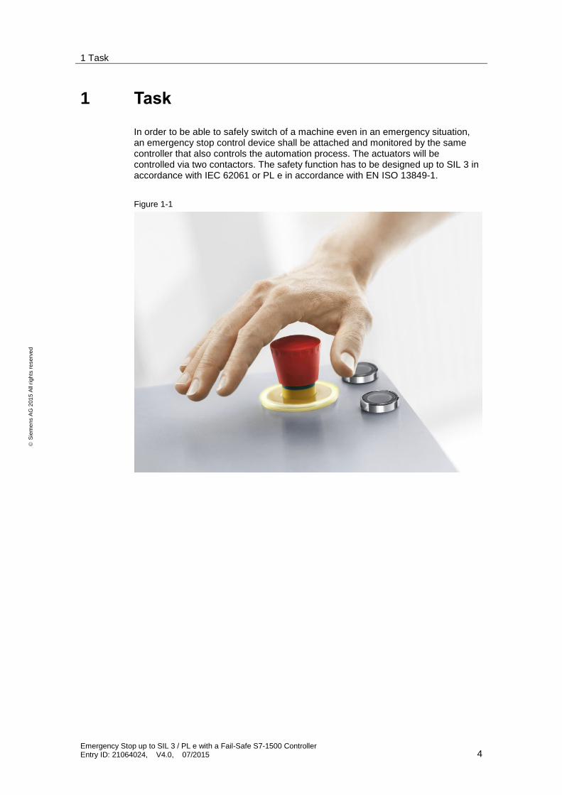
In order to be able to safely switch of a machine even in an emergency situation, an emergency stop control device shall be attached and monitored by the same controller that also controls the automation process. The actuators will be controlled via two contactors. The safety function has to be designed up to SIL 3 in accordance with IEC 62061 or PL e in accordance with EN ISO 13849-1.
Figure 1-1
2 Solution
2.1 Overview
Emergency Stop up to SIL 3 / PL e with a Fail-Safe S7-1500 Controller Entry ID: 21064024, V4.0, 07/2015 5
S
iem
en
s A
G 2
01
5 A
ll ri
gh
ts r
ese
rve
d
2 Solution
2.1 Overview
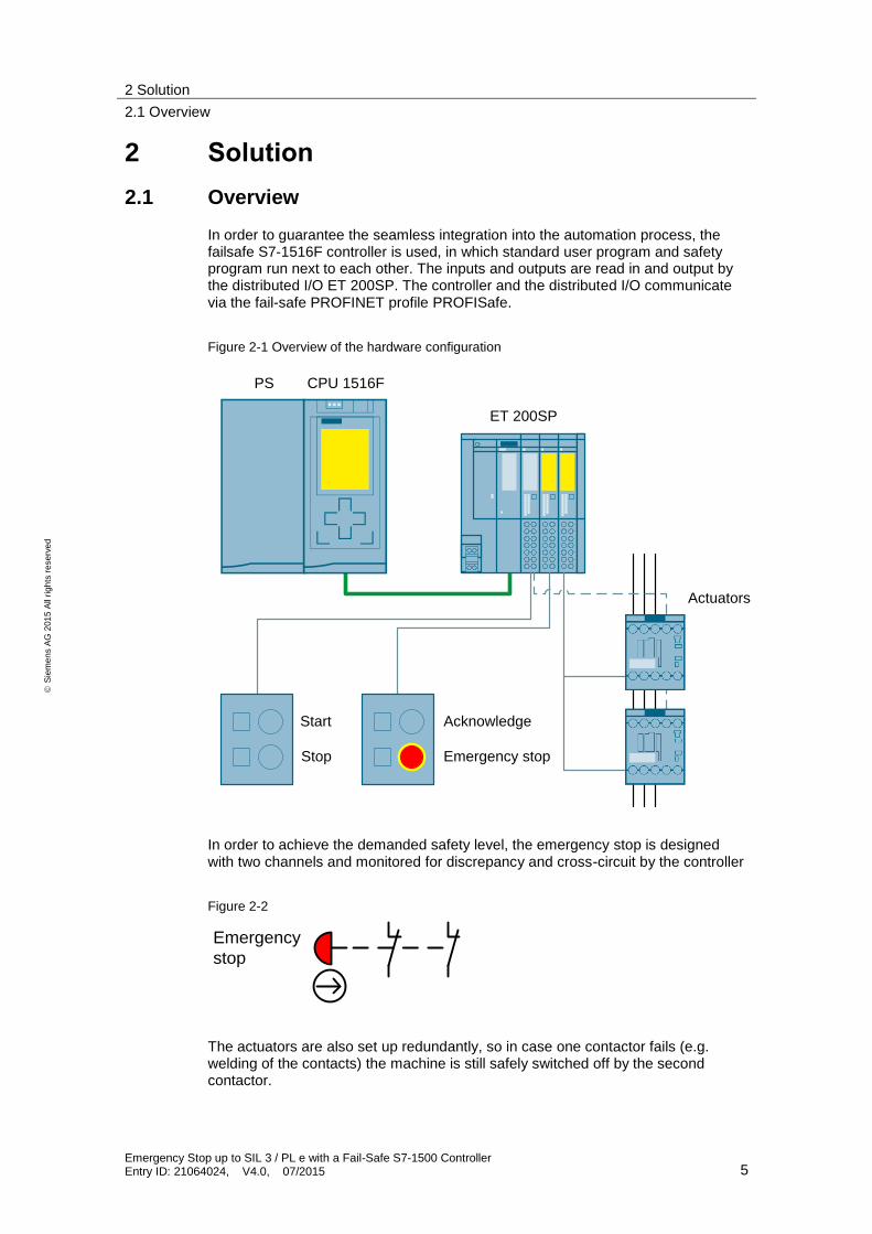
In order to guarantee the seamless integration into the automation process, the failsafe S7-1516F controller is used, in which standard user program and safety program run next to each other. The inputs and outputs are read in and output by the distributed I/O ET 200SP. The controller and the distributed I/O communicate via the fail-safe PROFINET profile PROFISafe.
Figure 2-1 Overview of the hardware configuration
CPU 1516F
ET 200SP
PS
Start Acknowledge
Emergency stop
Actuators
Stop
In order to achieve the demanded safety level, the emergency stop is designed with two channels and monitored for discrepancy and cross-circuit by the controller
Figure 2-2
Emergency
stop
The actuators are also set up redundantly, so in case one contactor fails (e.g. welding of the contacts) the machine is still safely switched off by the second contactor.
2 Solution
2.2 Description of the core functionality
Emergency Stop up to SIL 3 / PL e with a Fail-Safe S7-1500 Controller Entry ID: 21064024, V4.0, 07/2015 6
S
iem
en
s A
G 2
01
5 A
ll ri
gh
ts r
ese
rve
d
2.2 Description of the core functionality
In this application example the following functions are realized:
Resetting a failsafe digital output (stopping the application), after actuating the emergency stop button
Locking against a restart of the machine until the following conditions are fulfilled:
– Emergency stop is unlocked
– Acknowledgement has been given (does not automatically start the application)
– Start button is pressed (only possible with previous acknowledgement)
Monitoring the correct function of the contactors
Locking against a restart of the machine when a faulty contactor has been detected
2 Solution
2.3 Hardware and software components
Emergency Stop up to SIL 3 / PL e with a Fail-Safe S7-1500 Controller Entry ID: 21064024, V4.0, 07/2015 7
S
iem
en
s A
G 2
01
5 A
ll ri
gh
ts r
ese
rve
d
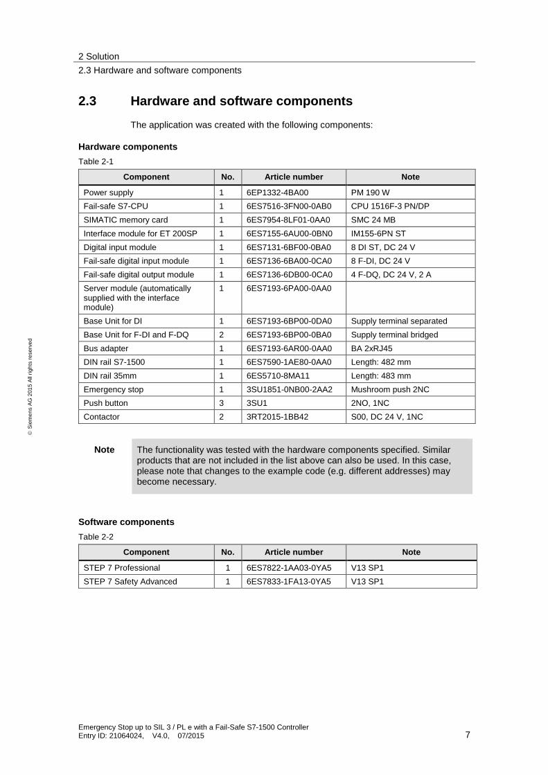
2.3 Hardware and software components
The application was created with the following components:
Hardware components
Table 2-1
Component No. Article number Note
Power supply 1 6EP1332-4BA00 PM 190 W
Fail-safe S7-CPU 1 6ES7516-3FN00-0AB0 CPU 1516F-3 PN/DP
SIMATIC memory card 1 6ES7954-8LF01-0AA0 SMC 24 MB
Interface module for ET 200SP 1 6ES7155-6AU00-0BN0 IM155-6PN ST
Digital input module 1 6ES7131-6BF00-0BA0 8 DI ST, DC 24 V
Fail-safe digital input module 1 6ES7136-6BA00-0CA0 8 F-DI, DC 24 V
Fail-safe digital output module 1 6ES7136-6DB00-0CA0 4 F-DQ, DC 24 V, 2 A
Server module (automatically supplied with the interface module)
1 6ES7193-6PA00-0AA0
Base Unit for DI 1 6ES7193-6BP00-0DA0 Supply terminal separated
Base Unit for F-DI and F-DQ 2 6ES7193-6BP00-0BA0 Supply terminal bridged
Bus adapter 1 6ES7193-6AR00-0AA0 BA 2xRJ45
DIN rail S7-1500 1 6ES7590-1AE80-0AA0 Length: 482 mm
DIN rail 35mm 1 6ES5710-8MA11 Length: 483 mm
Emergency stop 1 3SU1851-0NB00-2AA2 Mushroom push 2NC
Push button 3 3SU1 2NO, 1NC
Contactor 2 3RT2015-1BB42 S00, DC 24 V, 1NC
Note The functionality was tested with the hardware components specified. Similar products that are not included in the list above can also be used. In this case, please note that changes to the example code (e.g. different addresses) may become necessary.
Software components
Table 2-2
Component No. Article number Note
STEP 7 Professional 1 6ES7822-1AA03-0YA5 V13 SP1
STEP 7 Safety Advanced 1 6ES7833-1FA13-0YA5 V13 SP1
2 Solution
2.4 Advantages / customer benefits
Emergency Stop up to SIL 3 / PL e with a Fail-Safe S7-1500 Controller Entry ID: 21064024, V4.0, 07/2015 8
S
iem
en
s A
G 2
01
5 A
ll ri
gh
ts r
ese
rve
d
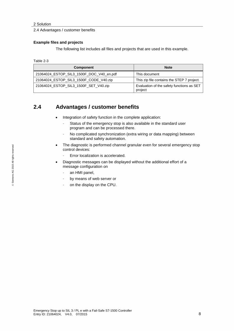
Example files and projects
The following list includes all files and projects that are used in this example.
Table 2-3
Component Note
21064024_ESTOP_SIL3_1500F_DOC_V40_en.pdf This document
21064024_ESTOP_SIL3_1500F_CODE_V40.zip This zip file contains the STEP 7 project.
21064024_ESTOP_SIL3_1500F_SET_V40.zip Evaluation of the safety functions as SET project
2.4 Advantages / customer benefits
Integration of safety function in the complete application:
– Status of the emergency stop is also available in the standard user program and can be processed there.
– No complicated synchronization (extra wiring or data mapping) between standard and safety automation.
The diagnostic is performed channel granular even for several emergency stop control devices:
– Error localization is accelerated.
Diagnostic messages can be displayed without the additional effort of a message configuration on
– an HMI panel,
– by means of web server or
– on the display on the CPU.
3 Basics
3.1 Basic terms
Emergency Stop up to SIL 3 / PL e with a Fail-Safe S7-1500 Controller Entry ID: 21064024, V4.0, 07/2015 9
S
iem
en
s A
G 2
01
5 A
ll ri
gh
ts r
ese
rve
d
3 Basics
3.1 Basic terms
Cross-circuit
The cross-circuit detection is a diagnostic function of an evaluation device, as a result of which short-circuits or cross-circuits are detected between the two input channels (sensor circuits).
A cross-circuit can occur, for example, if a light plastic-sheathed cable is crushed. Without cross-circuit detection this would lead to, for example, a 2-channel emergency stop circuit not to trigger a shut-down even if only one normally-closed contact is faulty (second error).
Feedback circuit
A feedback circuit is used for the monitoring of controlled actuators (e.g. relay or power contactors) with positively driven contacts or mirror contacts. The outputs can only be enabled when the feedback circuit is closed. When using a redundant switch off path, the feedback circuit of both actuators has to be evaluated. For this purpose, they may also be connected in series.
Positive opening operation
Positive opening switches are designed in a way that the operation of the switch inevitably leads to an opening of the contacts. Welded contacts are forced open through the operation (EN 60947-5-1).
Positively driven contacts
For a component with positively driven contacts it is guaranteed that the normally-closed and normally-open contacts are never closed at the same time (EN 60947-5-1).
3.2 Functional safety
From the view of the goods to be protected, safety is indivisible. However, since the causes of the hazards and therefore also the technical measures for avoiding them may be very different, the types of safety are also distinguished, for example, by specifying the respective cause of possible hazards. For this reason it is referred to “electrical safety” when hazards from electricity are expressed or “functional safety” when the safety depends on the correct function.
In order to achieve functional safety of a machine or plant, it is necessary for the safety-relevant parts of the protective equipment and control devices to function correctly and that they behave in a way that the plant stays in a safe state or is brought to a safe state in the event of an error.
3 Basics
3.3 Emergency stop
Emergency Stop up to SIL 3 / PL e with a Fail-Safe S7-1500 Controller Entry ID: 21064024, V4.0, 07/2015 10
S
iem
en
s A
G 2
01
5 A
ll ri
gh
ts r
ese
rve
d
A very high-quality technology is necessary to achieve this, where the requirements described in the appropriate standards are met. The requirements to achieve functional safety are based on the following basic targets:
avoidance of systematic faults
control of systematic faults
managing accidental errors or failures
The measure for the functional safety achieved, is the probability of dangerous failures, the error tolerance and the quality through which the freedom from systematic errors is to be guaranteed. This expressed in the standards through different terms:
In IEC 62061: “Safety Integrity Level” (SIL)
In ISO 13849-1: “Performance Level” (PL)
More information on function safety can be found in \8\.
3.3 Emergency stop
The emergency stop control device is a widely used component to protect personnel, plants and the environment from hazards and to initiate a standstill in the event of an emergency. This chapter describes applications with safety functions from exactly this range of application.
Facilities, functional aspects and general principles for design of the emergency stop are documented in EN ISO 13850. Additionally, the standard EN 60204-1 must also be observed.
Typical applications
The emergency stop control device with its positive opening contacts is monitored by an evaluation unit. If the emergency stop is pressed, the evaluation unit safely switches off the actuators according to stop category 0 in accordance with EN 60204-1. Before switching back on or acknowledging the emergency stop, it is checked whether the contacts of emergency stop control device are closed and the actuators are switched off.
Note Emergency stop is not a means of risk reduction. Emergency stop is an “additional safety function” (if the “emergency stop” has to be pressed, the motor must be switched off).
Unintentional actuation
It is often required that an emergency stop control device has to be protected from unintentional actuation and therefore to increase plant availability. The first step is the correct placement of the emergency stop control device on the machine. The emergency stop control device has to be easily accessible, easily reachable and safe to press.
3 Basics
3.3 Emergency stop
Emergency Stop up to SIL 3 / PL e with a Fail-Safe S7-1500 Controller Entry ID: 21064024, V4.0, 07/2015 11
S
iem
en
s A
G 2
01
5 A
ll ri
gh
ts r
ese
rve
d
In addition, there is the option to use a protective collar to protect from unintentional actuation. It also has to be made sure that easy accessibility is guaranteed.
Note SIEMENS SIRIUS emergency stop control devices with protective collar correspond to the requirements of EN ISO 13850 “Safety of machinery - Emergency stop - Principles for design”.
So far, no particular requirements exist for the protective collar, since they are not mentioned explicitly in any standard on functional safety. It is often at the discretion of the third-party expert to accept them for a certain machine.
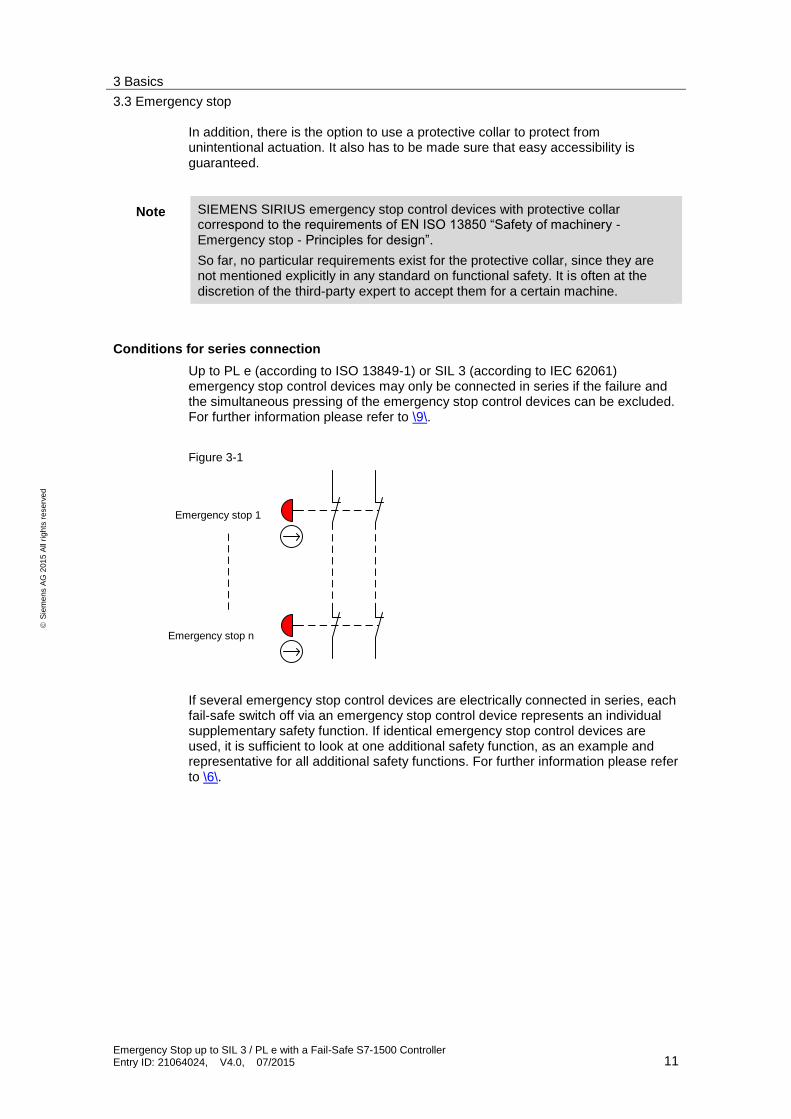
Conditions for series connection
Up to PL e (according to ISO 13849-1) or SIL 3 (according to IEC 62061) emergency stop control devices may only be connected in series if the failure and the simultaneous pressing of the emergency stop control devices can be excluded. For further information please refer to \9\.
Figure 3-1
Not-Halt 1
Not-Halt n
If several emergency stop control devices are electrically connected in series, each fail-safe switch off via an emergency stop control device represents an individual supplementary safety function. If identical emergency stop control devices are used, it is sufficient to look at one additional safety function, as an example and representative for all additional safety functions. For further information please refer to \6\.
Emergency stop 1
Emergency stop n
4 Mode of Operation
4.1 Overview
Emergency Stop up to SIL 3 / PL e with a Fail-Safe S7-1500 Controller Entry ID: 21064024, V4.0, 07/2015 12
S
iem
en
s A
G 2
01
5 A
ll ri
gh
ts r
ese
rve
d
4 Mode of Operation
4.1 Overview
The setup for realizing the emergency stop functionality consists of a configuration with PROFINET (PN) with PROFIsafe profile. A fail-safe S7-CPU (F-CPU) is used as IO controller and an ET 200SP is used as IO device. Two contactors are used as actuators.
NOTICE SIL 3 / PL e can only be achieved, if the function of the contactors is monitored in the feedback circuit.
For more information regarding the “Feedback circuit” topic, please refer to \3\.
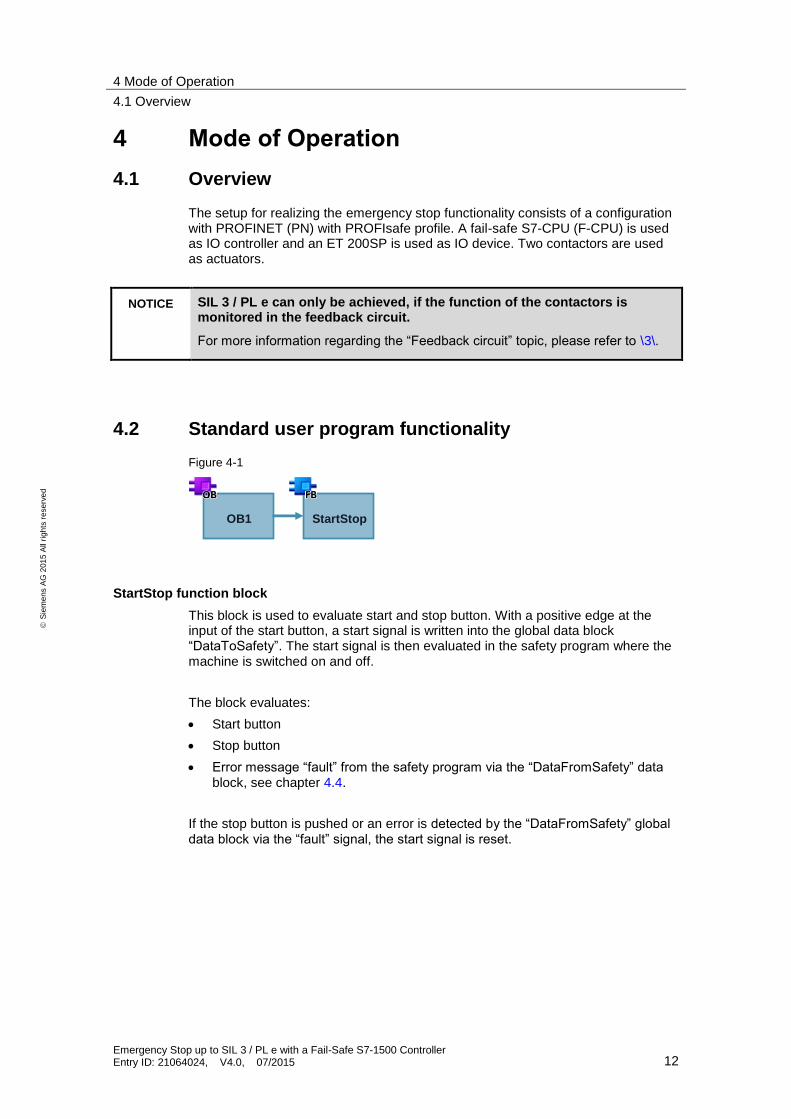
4.2 Standard user program functionality
Figure 4-1
OB1 StartStop
StartStop function block
This block is used to evaluate start and stop button. With a positive edge at the input of the start button, a start signal is written into the global data block “DataToSafety”. The start signal is then evaluated in the safety program where the machine is switched on and off.
The block evaluates:
Start button
Stop button
Error message “fault” from the safety program via the “DataFromSafety” data block, see chapter 4.4.
If the stop button is pushed or an error is detected by the “DataFromSafety” global data block via the “fault” signal, the start signal is reset.
4 Mode of Operation
4.3 Functionality of the safety program
Emergency Stop up to SIL 3 / PL e with a Fail-Safe S7-1500 Controller Entry ID: 21064024, V4.0, 07/2015 13
S
iem
en
s A
G 2
01
5 A
ll ri
gh
ts r
ese
rve
d
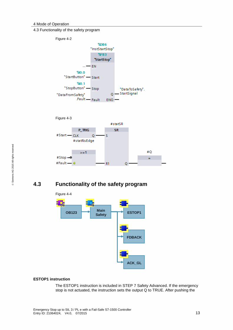
Figure 4-2
Figure 4-3
4.3 Functionality of the safety program
Figure 4-4
ACK_GL
FDBACK
ESTOP1Main
SafetyOB123
ESTOP1 instruction
The ESTOP1 instruction is included in STEP 7 Safety Advanced. If the emergency stop is not actuated, the instruction sets the output Q to TRUE. After pushing the
4 Mode of Operation
4.3 Functionality of the safety program
Emergency Stop up to SIL 3 / PL e with a Fail-Safe S7-1500 Controller Entry ID: 21064024, V4.0, 07/2015 14
S
iem
en
s A
G 2
01
5 A
ll ri
gh
ts r
ese
rve
d
emergency stop, it has to be unlocked and acknowledged via the ACK input. It is output via ACK_REQ that an acknowledgement is required. The Q output is intermediately saved in the temporary #tempEstopQ tag, in order to simplify access in the next instruction.
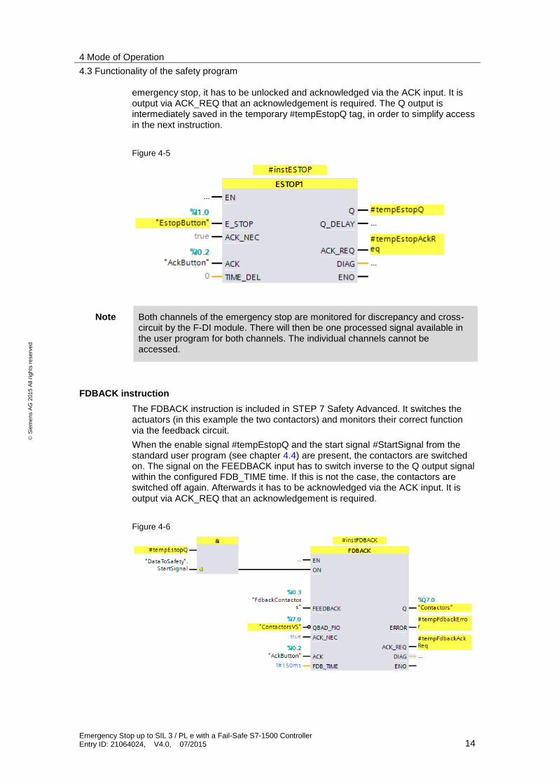
Figure 4-5
Note Both channels of the emergency stop are monitored for discrepancy and cross-circuit by the F-DI module. There will then be one processed signal available in the user program for both channels. The individual channels cannot be accessed.
FDBACK instruction
The FDBACK instruction is included in STEP 7 Safety Advanced. It switches the actuators (in this example the two contactors) and monitors their correct function via the feedback circuit.
When the enable signal #tempEstopQ and the start signal #StartSignal from the standard user program (see chapter 4.4) are present, the contactors are switched on. The signal on the FEEDBACK input has to switch inverse to the Q output signal within the configured FDB_TIME time. If this is not the case, the contactors are switched off again. Afterwards it has to be acknowledged via the ACK input. It is output via ACK_REQ that an acknowledgement is required.
Figure 4-6
4 Mode of Operation
4.3 Functionality of the safety program
Emergency Stop up to SIL 3 / PL e with a Fail-Safe S7-1500 Controller Entry ID: 21064024, V4.0, 07/2015 15
S
iem
en
s A
G 2
01
5 A
ll ri
gh
ts r
ese
rve
d
Note In the newer controllers S7-1200 and S7-1500, the channel granular QBAD bit is replaced by the value status. The following rules apply for the value status:
FALSE: Substitute values are output.
TRUE: Process values are output.
The value status behaves inversely to the QBAD bit and is entered into the process image of the inputs (PII).
For more information on the value status, please refer to \5\.
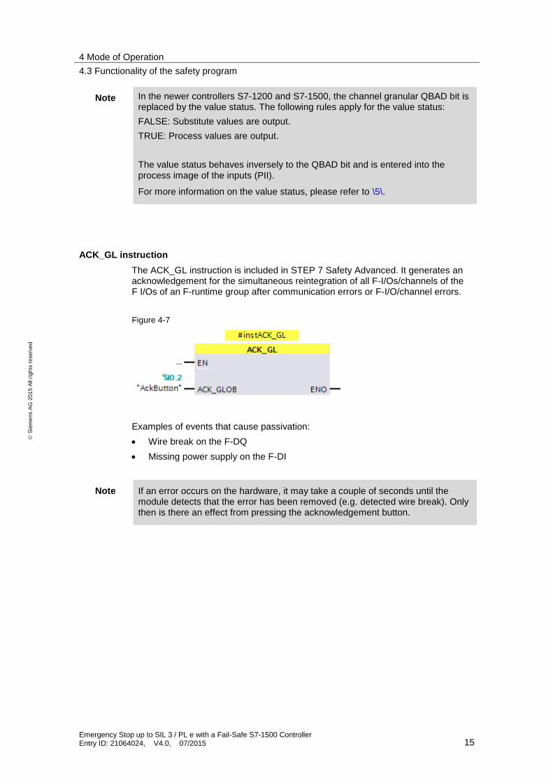
ACK_GL instruction
The ACK_GL instruction is included in STEP 7 Safety Advanced. It generates an acknowledgement for the simultaneous reintegration of all F-I/Os/channels of the F I/Os of an F-runtime group after communication errors or F-I/O/channel errors.
Figure 4-7
Examples of events that cause passivation:
Wire break on the F-DQ
Missing power supply on the F-DI
Note If an error occurs on the hardware, it may take a couple of seconds until the module detects that the error has been removed (e.g. detected wire break). Only then is there an effect from pressing the acknowledgement button.
4 Mode of Operation
4.4 Data exchange between standard user program and safety program
Emergency Stop up to SIL 3 / PL e with a Fail-Safe S7-1500 Controller Entry ID: 21064024, V4.0, 07/2015 16
S
iem
en
s A
G 2
01
5 A
ll ri
gh
ts r
ese
rve
d
4.4 Data exchange between standard user program and safety program
In order to exchange data between the standard user program and the safety program, two global data blocks are used:
DataToSafety
DataFromSafety
The DataToSafety data block is written by the standard user program and read by the safety program. The DataFromSafety data block is written by the standard user program and read by the safety program.
The processed “StartSignal” is transferred from the standard user program to the safety program. The safety program reports a fail-safe shutdown or errors in the safety program via the “fault” tag to the standard user program.
Note For more information about the data exchange between the standard user program and the safety program, please refer to \5\.
5 Configuration and Settings
5.1 Configuration of S7-1500 F-CPU
Emergency Stop up to SIL 3 / PL e with a Fail-Safe S7-1500 Controller Entry ID: 21064024, V4.0, 07/2015 17
S
iem
en
s A
G 2
01
5 A
ll ri
gh
ts r
ese
rve
d
5 Configuration and Settings
The enclosed project does not require any further configuration. If you want to replicate the application example with other components, then the most important settings are shown in this chapter.
NOTICE The settings displayed below help to meet PL e / SIL 3. Changes on the settings may cause loss of the safety function.
NOTICE The default values used in the example projects may also differ from your individual requirements.
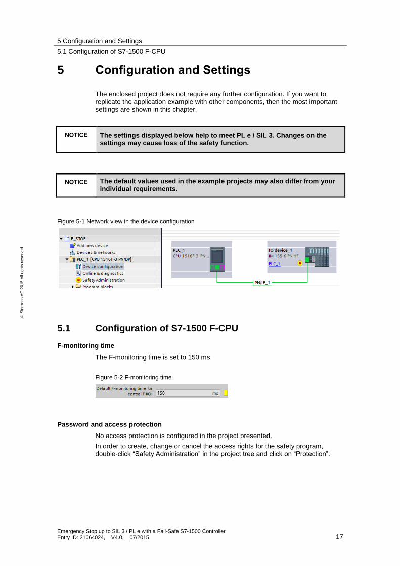
Figure 5-1 Network view in the device configuration
5.1 Configuration of S7-1500 F-CPU
F-monitoring time
The F-monitoring time is set to 150 ms.
Figure 5-2 F-monitoring time
Password and access protection
No access protection is configured in the project presented.
In order to create, change or cancel the access rights for the safety program, double-click “Safety Administration” in the project tree and click on “Protection”.
5 Configuration and Settings
5.2 Configuration of the distributed I/O
Emergency Stop up to SIL 3 / PL e with a Fail-Safe S7-1500 Controller Entry ID: 21064024, V4.0, 07/2015 18
S
iem
en
s A
G 2
01
5 A
ll ri
gh
ts r
ese
rve
d
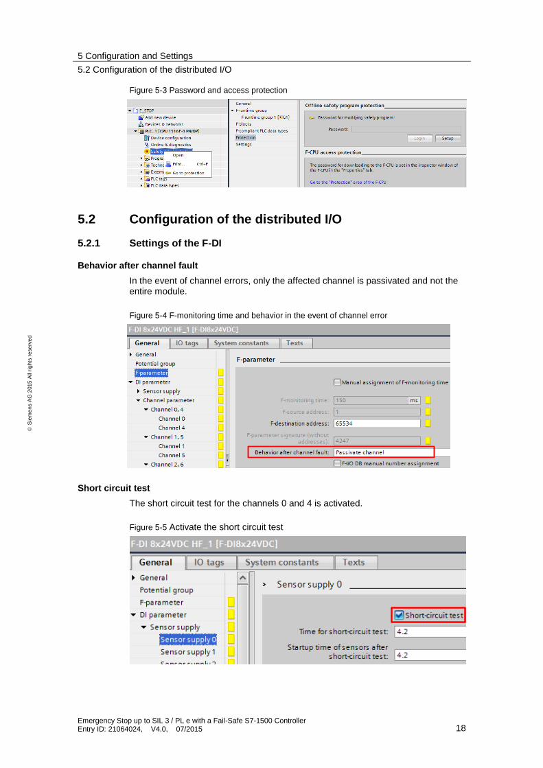
Figure 5-3 Password and access protection
5.2 Configuration of the distributed I/O
5.2.1 Settings of the F-DI
Behavior after channel fault
In the event of channel errors, only the affected channel is passivated and not the entire module.
Figure 5-4 F-monitoring time and behavior in the event of channel error
Short circuit test
The short circuit test for the channels 0 and 4 is activated.
Figure 5-5 Activate the short circuit test
5 Configuration and Settings
5.2 Configuration of the distributed I/O
Emergency Stop up to SIL 3 / PL e with a Fail-Safe S7-1500 Controller Entry ID: 21064024, V4.0, 07/2015 19
S
iem
en
s A
G 2
01
5 A
ll ri
gh
ts r
ese
rve
d
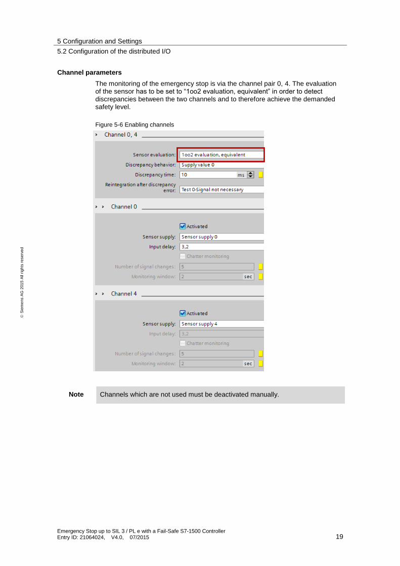
Channel parameters
The monitoring of the emergency stop is via the channel pair 0, 4. The evaluation of the sensor has to be set to “1oo2 evaluation, equivalent” in order to detect discrepancies between the two channels and to therefore achieve the demanded safety level.
Figure 5-6 Enabling channels
Note Channels which are not used must be deactivated manually.
5 Configuration and Settings
5.2 Configuration of the distributed I/O
Emergency Stop up to SIL 3 / PL e with a Fail-Safe S7-1500 Controller Entry ID: 21064024, V4.0, 07/2015 20
S
iem
en
s A
G 2
01
5 A
ll ri
gh
ts r
ese
rve
d
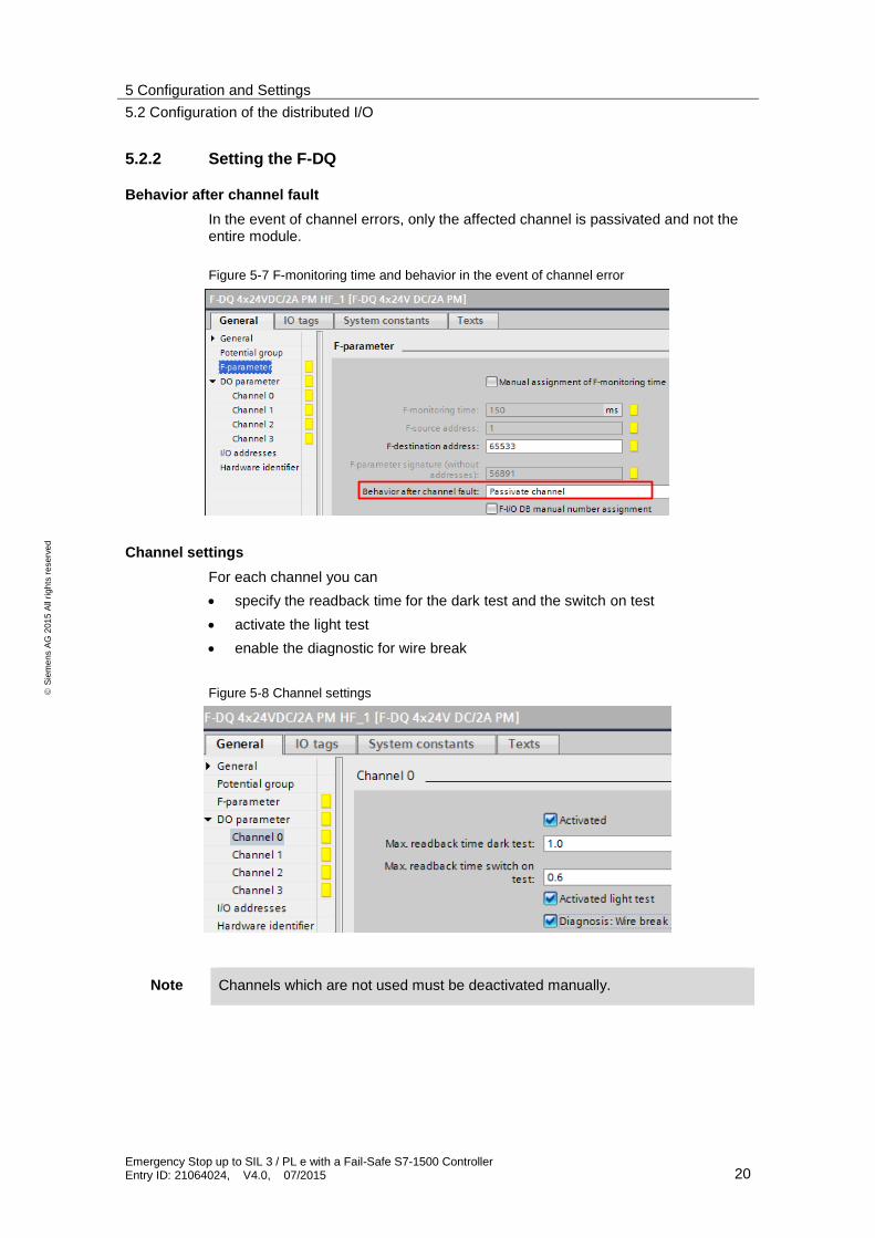
5.2.2 Setting the F-DQ
Behavior after channel fault
In the event of channel errors, only the affected channel is passivated and not the entire module.
Figure 5-7 F-monitoring time and behavior in the event of channel error
Channel settings
For each channel you can
specify the readback time for the dark test and the switch on test
activate the light test
enable the diagnostic for wire break
Figure 5-8 Channel settings
Note Channels which are not used must be deactivated manually.
6 Installation and Commissioning
6.1 Installing the hardware
Emergency Stop up to SIL 3 / PL e with a Fail-Safe S7-1500 Controller Entry ID: 21064024, V4.0, 07/2015 21
S
iem
en
s A
G 2
01
5 A
ll ri
gh
ts r
ese
rve
d
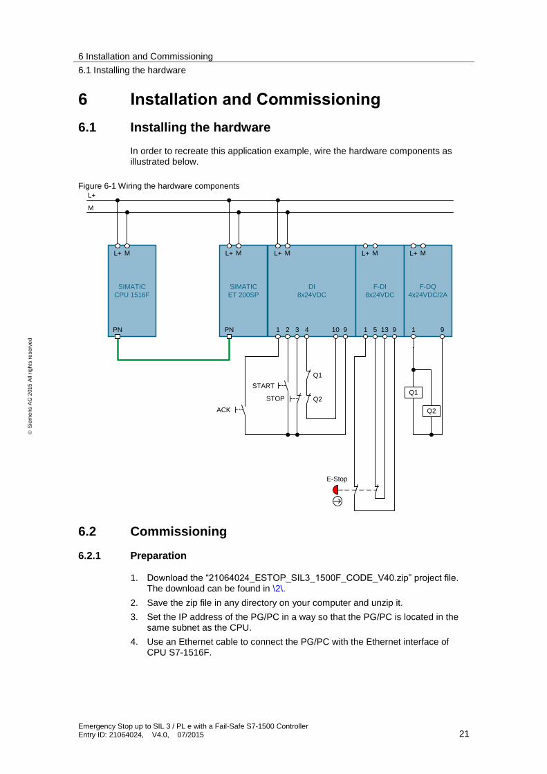
6 Installation and Commissioning
6.1 Installing the hardware
In order to recreate this application example, wire the hardware components as illustrated below.
Figure 6-1 Wiring the hardware components
DI
8x24VDC
L+ M
1 2 3 910
F-DI
8x24VDC
L+ M
1 5 913
F-DQ
4x24VDC/2A
L+ M
1 9
Q1
Q2
E-Stop
START
ACK
Q1
Q2
L+
M
SIMATIC
CPU 1516F
L+ M
PN
SIMATIC
ET 200SP
L+ M
PN
STOP
4
6.2 Commissioning
6.2.1 Preparation
1. Download the “21064024_ESTOP_SIL3_1500F_CODE_V40.zip” project file. The download can be found in \2\.
2. Save the zip file in any directory on your computer and unzip it.
3. Set the IP address of the PG/PC in a way so that the PG/PC is located in the same subnet as the CPU.
4. Use an Ethernet cable to connect the PG/PC with the Ethernet interface of CPU S7-1516F.
6 Installation and Commissioning
6.2 Commissioning
Emergency Stop up to SIL 3 / PL e with a Fail-Safe S7-1500 Controller Entry ID: 21064024, V4.0, 07/2015 22
S
iem
en
s A
G 2
01
5 A
ll ri
gh
ts r
ese
rve
d
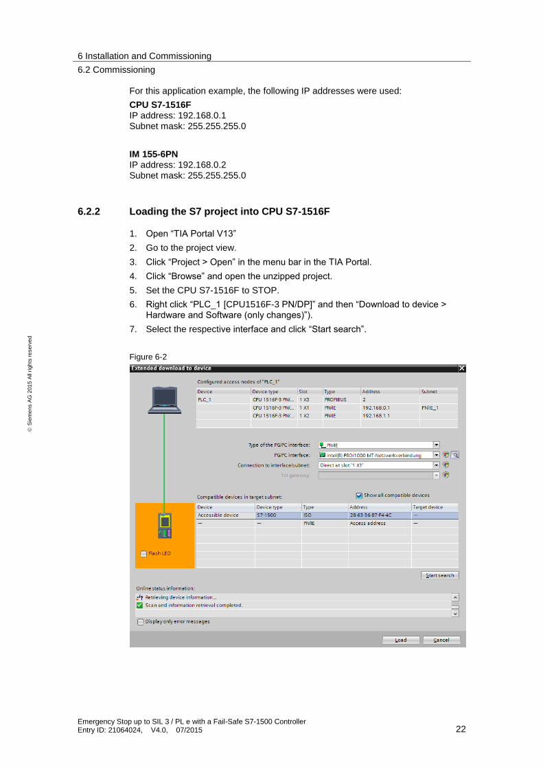
For this application example, the following IP addresses were used:
CPU S7-1516F IP address: 192.168.0.1 Subnet mask: 255.255.255.0
IM 155-6PN IP address: 192.168.0.2 Subnet mask: 255.255.255.0
6.2.2 Loading the S7 project into CPU S7-1516F
1. Open “TIA Portal V13”
2. Go to the project view.
3. Click “Project > Open” in the menu bar in the TIA Portal.
4. Click “Browse” and open the unzipped project.
5. Set the CPU S7-1516F to STOP.
6. Right click “PLC_1 [CPU1516F-3 PN/DP]” and then “Download to device > Hardware and Software (only changes)”).
7. Select the respective interface and click “Start search”.
Figure 6-2
6 Installation and Commissioning
6.2 Commissioning
Emergency Stop up to SIL 3 / PL e with a Fail-Safe S7-1500 Controller Entry ID: 21064024, V4.0, 07/2015 23
S
iem
en
s A
G 2
01
5 A
ll ri
gh
ts r
ese
rve
d
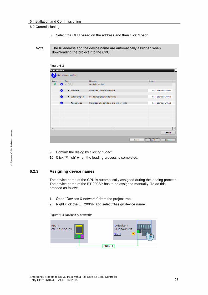
8. Select the CPU based on the address and then click “Load”.
Note The IP address and the device name are automatically assigned when downloading the project into the CPU.
Figure 6-3
9. Confirm the dialog by clicking “Load”.
10. Click “Finish” when the loading process is completed.
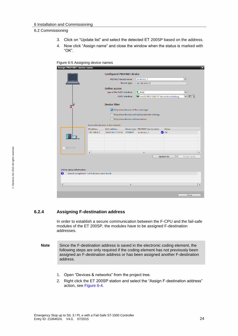
6.2.3 Assigning device names
The device name of the CPU is automatically assigned during the loading process. The device name of the ET 200SP has to be assigned manually. To do this, proceed as follows:
1. Open “Devices & networks” from the project tree.
2. Right click the ET 200SP and select “Assign device name”.
Figure 6-4 Devices & networks
6 Installation and Commissioning
6.2 Commissioning
Emergency Stop up to SIL 3 / PL e with a Fail-Safe S7-1500 Controller Entry ID: 21064024, V4.0, 07/2015 24
S
iem
en
s A
G 2
01
5 A
ll ri
gh
ts r
ese
rve
d
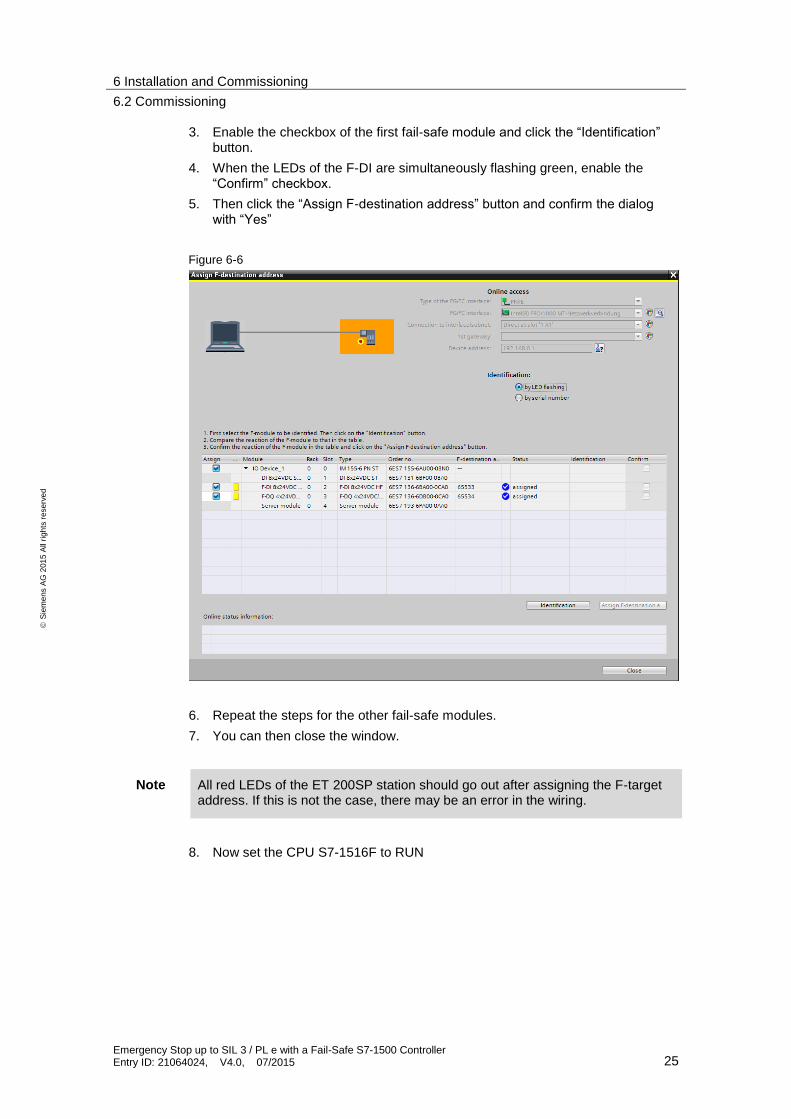
3. Click on “Update list” and select the detected ET 200SP based on the address.
4. Now click “Assign name” and close the window when the status is marked with “OK”.
Figure 6-5 Assigning device names
6.2.4 Assigning F-destination address
In order to establish a secure communication between the F-CPU and the fail-safe modules of the ET 200SP, the modules have to be assigned F-destination addresses.
Note Since the F-destination address is saved in the electronic coding element, the following steps are only required if the coding element has not previously been assigned an F-destination address or has been assigned another F-destination address.
1. Open “Devices & networks” from the project tree.
2. Right click the ET 200SP station and select the “Assign F-destination address” action, see Figure 6-4.
6 Installation and Commissioning
6.2 Commissioning
Emergency Stop up to SIL 3 / PL e with a Fail-Safe S7-1500 Controller Entry ID: 21064024, V4.0, 07/2015 25
S
iem
en
s A
G 2
01
5 A
ll ri
gh
ts r
ese
rve
d
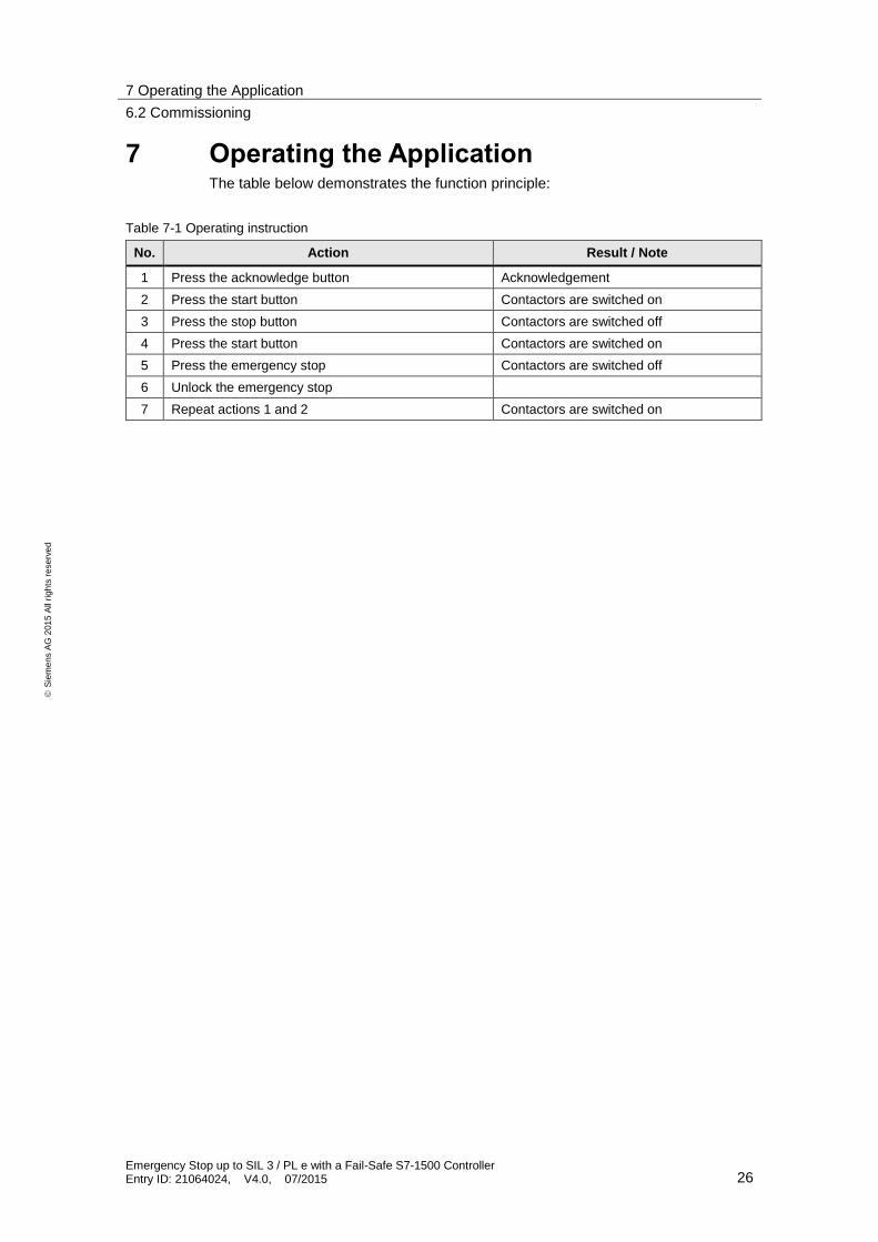
3. Enable the checkbox of the first fail-safe module and click the “Identification” button.
4. When the LEDs of the F-DI are simultaneously flashing green, enable the “Confirm” checkbox.
5. Then click the “Assign F-destination address” button and confirm the dialog with “Yes”
Figure 6-6
6. Repeat the steps for the other fail-safe modules.
7. You can then close the window.
Note All red LEDs of the ET 200SP station should go out after assigning the F-target address. If this is not the case, there may be an error in the wiring.
8. Now set the CPU S7-1516F to RUN
7 Operating the Application
6.2 Commissioning
Emergency Stop up to SIL 3 / PL e with a Fail-Safe S7-1500 Controller Entry ID: 21064024, V4.0, 07/2015 26
S
iem
en
s A
G 2
01
5 A
ll ri
gh
ts r
ese
rve
d
7 Operating the Application The table below demonstrates the function principle:
Table 7-1 Operating instruction
No. Action Result / Note
1 Press the acknowledge button Acknowledgement
2 Press the start button Contactors are switched on
3 Press the stop button Contactors are switched off
4 Press the start button Contactors are switched on
5 Press the emergency stop Contactors are switched off
6 Unlock the emergency stop
7 Repeat actions 1 and 2 Contactors are switched on
8 Evaluation of the Safety Function
8.1 Standards
Emergency Stop up to SIL 3 / PL e with a Fail-Safe S7-1500 Controller Entry ID: 21064024, V4.0, 07/2015 27
S
iem
en
s A
G 2
01
5 A
ll ri
gh
ts r
ese
rve
d
8 Evaluation of the Safety Function
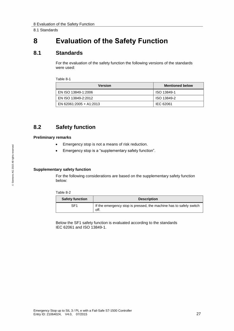
8.1 Standards
For the evaluation of the safety function the following versions of the standards were used:
Table 8-1
Version Mentioned below
EN ISO 13849-1:2006 ISO 13849-1
EN ISO 13849-2:2012 ISO 13849-2
EN 62061:2005 + A1:2013 IEC 62061
8.2 Safety function
Preliminary remarks
Emergency stop is not a means of risk reduction.
Emergency stop is a “supplementary safety function”.
Supplementary safety function
For the following considerations are based on the supplementary safety function below:
Table 8-2
Safety function Description
SF1 If the emergency stop is pressed, the machine has to safely switch off.
Below the SF1 safety function is evaluated according to the standards IEC 62061 and ISO 13849-1.
8 Evaluation of the Safety Function
8.3 Evaluation according to IEC 62061
Emergency Stop up to SIL 3 / PL e with a Fail-Safe S7-1500 Controller Entry ID: 21064024, V4.0, 07/2015 28
S
iem
en
s A
G 2
01
5 A
ll ri
gh
ts r
ese
rve
d
8.3 Evaluation according to IEC 62061
Below, the evaluation according to IEC 62061 is carried out with the Safety Evaluation Tool (SET). For the link to the SET, refer to the Internet in \4\.
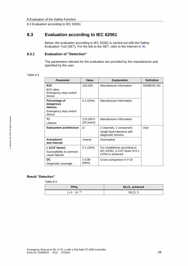
8.3.1 Evaluation of "Detection"
The parameters relevant for the evaluation are provided by the manufacturer and specified by the user.
Table 8-3
Parameter Value Explanation Definition
B10
B10 value Emergency stop control device
100.000 Manufacturer information SIEMENS AG
Percentage of dangerous failures
Emergency stop control device
0.2 (20%) Manufacturer information
T1
Lifetime
175,200 h (20 years)
Manufacturer information
Subsystem architecture D 2 channels, 1 component:
Single fault tolerance with diagnostic function
User
Actuations/ test interval
1/week Assumption
(CCF factor)
Susceptibility to common cause failures
0.1 (10%) For installations according to IEC 62061, a CCF factor of 0.1 (10%) is achieved.
DC
Diagnostic coverage
≥ 0.99 (99%)
Cross-comparison in F-DI
Result “Detection”
Table 8-4
PFHD SILCL achieved
1.19 ∙ 10−10 SILCL 3
8 Evaluation of the Safety Function
8.3 Evaluation according to IEC 62061
Emergency Stop up to SIL 3 / PL e with a Fail-Safe S7-1500 Controller Entry ID: 21064024, V4.0, 07/2015 29
S
iem
en
s A
G 2
01
5 A
ll ri
gh
ts r
ese
rve
d
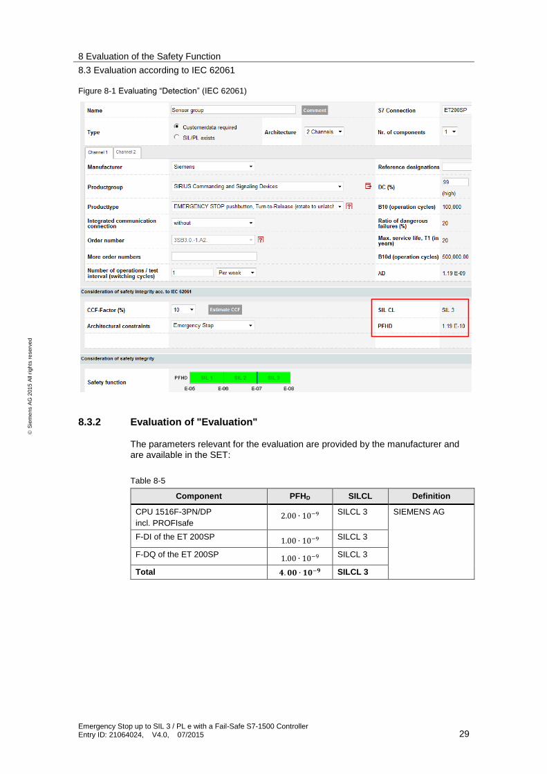
Figure 8-1 Evaluating “Detection” (IEC 62061)
8.3.2 Evaluation of "Evaluation"
The parameters relevant for the evaluation are provided by the manufacturer and are available in the SET:
Table 8-5
Component PFHD SILCL Definition
CPU 1516F-3PN/DP
incl. PROFIsafe 2.00 ∙ 10−9 SILCL 3 SIEMENS AG
F-DI of the ET 200SP 1.00 ∙ 10−9 SILCL 3
F-DQ of the ET 200SP 1.00 ∙ 10−9 SILCL 3
Total 𝟒. 𝟎𝟎 ∙ 𝟏𝟎−𝟗 SILCL 3
8 Evaluation of the Safety Function
8.3 Evaluation according to IEC 62061
Emergency Stop up to SIL 3 / PL e with a Fail-Safe S7-1500 Controller Entry ID: 21064024, V4.0, 07/2015 30
S
iem
en
s A
G 2
01
5 A
ll ri
gh
ts r
ese
rve
d
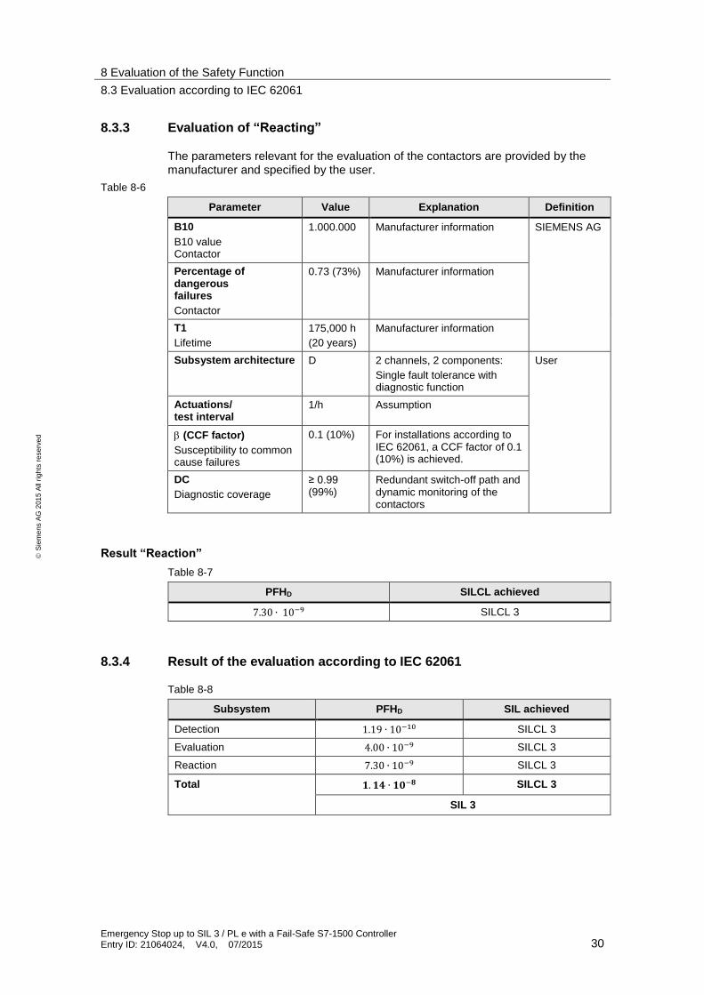
8.3.3 Evaluation of “Reacting”
The parameters relevant for the evaluation of the contactors are provided by the manufacturer and specified by the user.
Table 8-6
Parameter Value Explanation Definition
B10
B10 value Contactor
1.000.000 Manufacturer information SIEMENS AG
Percentage of dangerous failures
Contactor
0.73 (73%) Manufacturer information
T1
Lifetime
175,000 h
(20 years)
Manufacturer information
Subsystem architecture D 2 channels, 2 components:
Single fault tolerance with diagnostic function
User
Actuations/ test interval
1/h Assumption
(CCF factor)
Susceptibility to common cause failures
0.1 (10%) For installations according to IEC 62061, a CCF factor of 0.1 (10%) is achieved.
DC
Diagnostic coverage
≥ 0.99 (99%)
Redundant switch-off path and dynamic monitoring of the contactors
Result “Reaction”
Table 8-7
PFHD SILCL achieved
7.30 ∙ 10−9 SILCL 3
8.3.4 Result of the evaluation according to IEC 62061
Table 8-8
Subsystem PFHD SIL achieved
Detection 1.19 ∙ 10−10 SILCL 3
Evaluation 4.00 ∙ 10−9 SILCL 3
Reaction 7.30 ∙ 10−9 SILCL 3
Total 𝟏. 𝟏𝟒 ∙ 𝟏𝟎−𝟖 SILCL 3
SIL 3
8 Evaluation of the Safety Function
8.4 Evaluation according to ISO 13849-1
Emergency Stop up to SIL 3 / PL e with a Fail-Safe S7-1500 Controller Entry ID: 21064024, V4.0, 07/2015 31
S
iem
en
s A
G 2
01
5 A
ll ri
gh
ts r
ese
rve
d
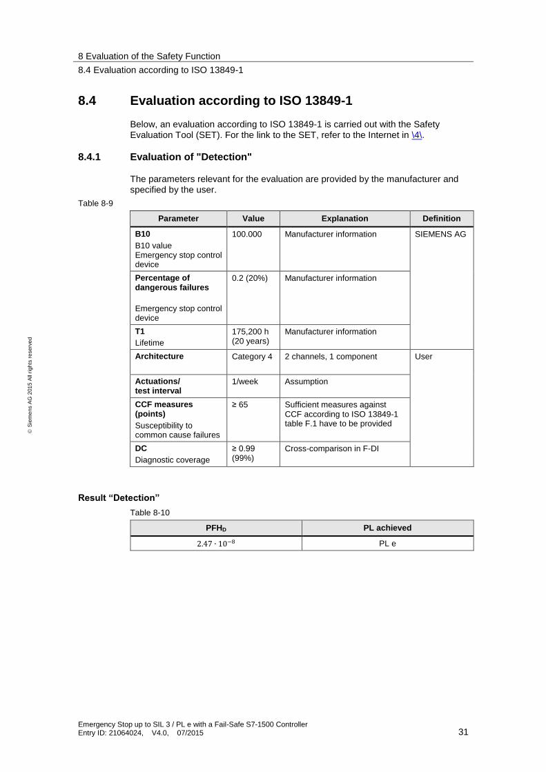
8.4 Evaluation according to ISO 13849-1
Below, an evaluation according to ISO 13849-1 is carried out with the Safety Evaluation Tool (SET). For the link to the SET, refer to the Internet in \4\.
8.4.1 Evaluation of "Detection"
The parameters relevant for the evaluation are provided by the manufacturer and specified by the user.
Table 8-9
Parameter Value Explanation Definition
B10
B10 value Emergency stop control device
100.000 Manufacturer information SIEMENS AG
Percentage of dangerous failures
Emergency stop control device
0.2 (20%) Manufacturer information
T1
Lifetime
175,200 h (20 years)
Manufacturer information
Architecture Category 4 2 channels, 1 component
User
Actuations/ test interval
1/week Assumption
CCF measures (points)
Susceptibility to common cause failures
≥ 65 Sufficient measures against CCF according to ISO 13849-1 table F.1 have to be provided
DC
Diagnostic coverage
≥ 0.99 (99%)
Cross-comparison in F-DI
Result “Detection”
Table 8-10
PFHD PL achieved
2.47 ∙ 10−8 PL e
8 Evaluation of the Safety Function
8.4 Evaluation according to ISO 13849-1
Emergency Stop up to SIL 3 / PL e with a Fail-Safe S7-1500 Controller Entry ID: 21064024, V4.0, 07/2015 32
S
iem
en
s A
G 2
01
5 A
ll ri
gh
ts r
ese
rve
d
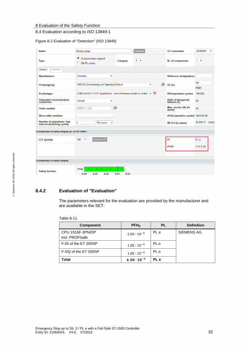
Figure 8-2 Evaluation of "Detection" (ISO 13849)
8.4.2 Evaluation of "Evaluation"
The parameters relevant for the evaluation are provided by the manufacturer and are available in the SET:
Table 8-11
Component PFHD PL Definition
CPU 1516F-3PN/DP
incl. PROFIsafe 2.00 ∙ 10−9 PL e SIEMENS AG
F-DI of the ET 200SP 1.00 ∙ 10−9 PL e
F-DQ of the ET 200SP 1.00 ∙ 10−9 PL e
Total 𝟒. 𝟎𝟎 ∙ 𝟏𝟎−𝟗 PL e
8 Evaluation of the Safety Function
8.4 Evaluation according to ISO 13849-1
Emergency Stop up to SIL 3 / PL e with a Fail-Safe S7-1500 Controller Entry ID: 21064024, V4.0, 07/2015 33
S
iem
en
s A
G 2
01
5 A
ll ri
gh
ts r
ese
rve
d
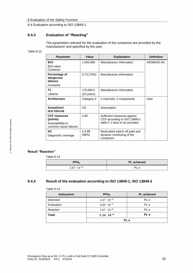
8.4.3 Evaluation of “Reacting”
The parameters relevant for the evaluation of the contactors are provided by the manufacturer and specified by the user.
Table 8-12
Parameter Value Explanation Definition
B10
B10 value Contactor
1.000.000 Manufacturer information SIEMENS AG
Percentage of dangerous failures
Contactor
0.73 (73%) Manufacturer information
T1
Lifetime
175,000 h
(20 years)
Manufacturer information
Architecture Category 4 2 channels, 2 components
User
Actuations/ test interval
1/h Assumption
CCF measures (points)
Susceptibility to common cause failures
≥ 65 Sufficient measures against CCF according to ISO 13849-1 table F.1 have to be provided
DC
Diagnostic coverage
≥ 0.99 (99%)
Redundant switch-off path and dynamic monitoring of the contactors
Result “Reaction”
Table 8-13
PFHD PL achieved
2.47 ∙ 10−8 PL e
8.4.4 Result of the evaluation according to ISO 13849-1, ISO 13849-2
Table 8-14
Subsystem PFHD PL achieved
Detection 2.47 ∙ 10−8 PL e
Evaluation 4.00 ∙ 10−9 PL e
Reaction 2.47 ∙ 10−8 PL e
Total 𝟓. 𝟑𝟒 ∙ 𝟏𝟎−𝟖 PL e
PL e
9 Links & Literature
8.4 Evaluation according to ISO 13849-1
Emergency Stop up to SIL 3 / PL e with a Fail-Safe S7-1500 Controller Entry ID: 21064024, V4.0, 07/2015 34
S
iem
en
s A
G 2
01
5 A
ll ri
gh
ts r
ese
rve
d
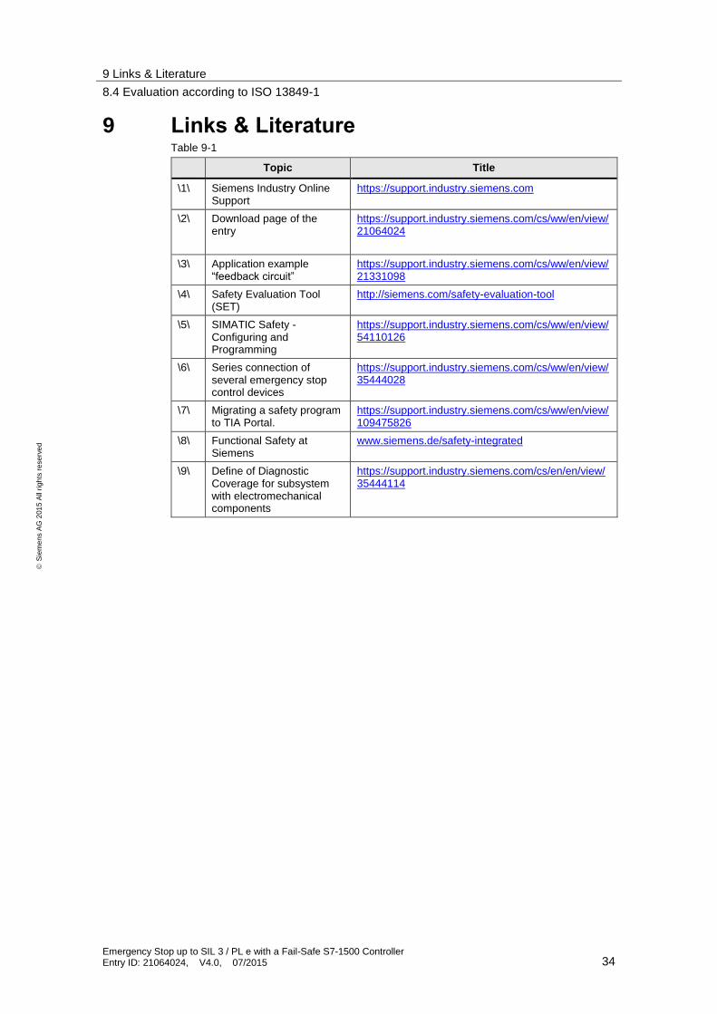
9 Links & Literature Table 9-1
Topic Title
\1\ Siemens Industry Online Support
https://support.industry.siemens.com
\2\ Download page of the entry
https://support.industry.siemens.com/cs/ww/en/view/21064024
\3\ Application example “feedback circuit”
https://support.industry.siemens.com/cs/ww/en/view/21331098
\4\ Safety Evaluation Tool (SET)
http://siemens.com/safety-evaluation-tool
\5\ SIMATIC Safety - Configuring and Programming
https://support.industry.siemens.com/cs/ww/en/view/54110126
\6\ Series connection of several emergency stop control devices
https://support.industry.siemens.com/cs/ww/en/view/35444028
\7\ Migrating a safety program to TIA Portal.
https://support.industry.siemens.com/cs/ww/en/view/109475826
\8\ Functional Safety at Siemens
www.siemens.de/safety-integrated
\9\ Define of Diagnostic Coverage for subsystem with electromechanical components
https://support.industry.siemens.com/cs/en/en/view/35444114
10 History
8.4 Evaluation according to ISO 13849-1
Emergency Stop up to SIL 3 / PL e with a Fail-Safe S7-1500 Controller Entry ID: 21064024, V4.0, 07/2015 35
S
iem
en
s A
G 2
01
5 A
ll ri
gh
ts r
ese
rve
d
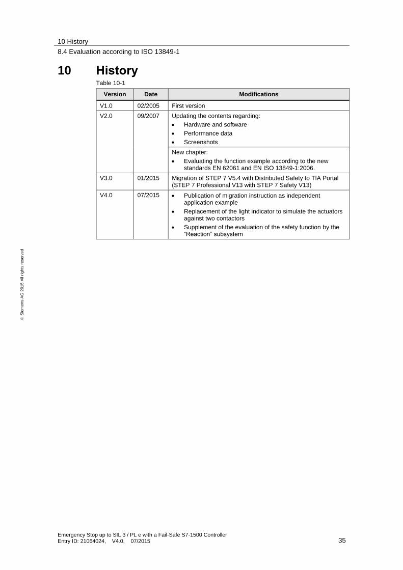
10 History Table 10-1
Version Date Modifications
V1.0 02/2005 First version
V2.0
09/2007 Updating the contents regarding:
Hardware and software
Performance data
Screenshots
New chapter:
Evaluating the function example according to the new standards EN 62061 and EN ISO 13849-1:2006.
V3.0 01/2015 Migration of STEP 7 V5.4 with Distributed Safety to TIA Portal (STEP 7 Professional V13 with STEP 7 Safety V13)
V4.0 07/2015 Publication of migration instruction as independent application example
Replacement of the light indicator to simulate the actuators against two contactors
Supplement of the evaluation of the safety function by the “Reaction” subsystem