Embed Size (px)
Citation preview
LAT Environmental Test PDR 1
GLAST LAT Project 3-4 May 2005
LAT Environmental Test Planning and Design Review
3-4 May 2005
EMI/EMC
LAT Environmental Test Planning and Design ReviewLAT Environmental Test Planning and Design Review
33--4 May 20054 May 2005
EMI/EMCEMI/EMC
Michael N. LovelletteMichael N. Lovellette

LAT Environmental Test PDR 2
GLAST LAT Project 3-4 May 2005
LAT EMI TestLAT EMI Test
• LAT test levels derived from 433-RQMT-0005_RevA & LAT-SS-0778
• Draft EMI/EMC Test Plan: LAT-MD-00276-02– Use CAL EMI test procedure as template– LAT-PS-03929-03
• Test Suite:– CE102 Conducted Emissions, Power Leads, 10 kHz to 10 MHz, MIL-STD-462, CE03– CECM Conducted Emissions, Time Domain, 150 MHz Bandwidth– CS102 Conducted Susceptibility, Power Leads, 10 kHz to 10 MHz, MIL-STD-462, CS02– CSCM Conducted Susceptibility, Common Mode, 30 Hz to 150 MHz, MIL-STD-462, CS02– CS06 Conducted Susceptibility, Spike, Power Leads, MIL-STD-462– RE101 Radiated Emissions, Magnetic Field, 20 Hz to 50 kHz– RE102 Radiated Emissions, Electric Field, 10 kHz to 18 GHz, MIL-STD-461E– RS101 Radiated Susceptibility, Magnetic Field, 20 Hz to 50 kHz– RS103 Radiated Susceptibility, Electric Field, 30 MHz to 18 GHz
LAT Environmental Test PDR 3
GLAST LAT Project 3-4 May 2005
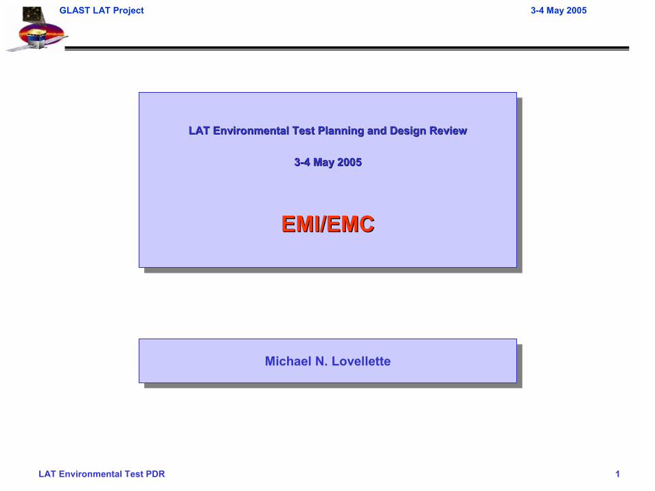
LAT Power InterfacesLAT Power Interfaces
• SC-LAT Power Interfaces– SC PRU (P) - LAT PDU– SC PRU (R) - LAT PDU– SC PRU (P) - LAT SIU (P)– SC PRU (R) - LAT SIU (R)– SC PRU (P) - LAT VCHP +Y– SC PRU (P) - LAT VCHP -Y– SC PRU (R) - LAT VCHP +Y– SC PRU (R) - LAT VCHP -Y– SC PDU (P) - LAT MAKEUP– SC PDU (R) - LAT MAKEUP
LAT Environmental Test PDR 4
GLAST LAT Project 3-4 May 2005
Test LimitationsTest Limitations
• Deviations from nominal test
– RS103 upper limit of 18GHz (40GHz)
– Limited area of RS101 test• Requires scanning each 10cm x 10cm area, ~16min/scan• ~1450 scans for the LAT, another ~1200 for the radiators (~29 days)• Scan selected locations around connectors, PMTs, BEA
– LAT EGSE power supplies will be used for all EMI/EMC testing, no attempt will be made to duplicate expected characteristics of the S/V power
– Limited B side conducted testing• Emissions tests and susceptibility only where noted on A side
– No heater circuit testing

LAT Environmental Test PDR 5
GLAST LAT Project 3-4 May 2005
Open IssuesOpen Issues
• Replace CSCM as run for CAL EMI with MIL-STD 461E CS114 derived CSCM test
• Update RE102 limits per proposal from Fred Blanchett
LAT Environmental Test PDR 6
GLAST LAT Project 3-4 May 2005
EMI Test ConfigurationsEMI Test Configurations
• Split EMI test– Conducted tests performed in the high bay integration area– Radiated testing performed in anechoic chamber
• Conducted emissions and susceptibility tests with SIU and PDU do not require radiators, but do require good access to connectors
LAT Environmental Test PDR 7
GLAST LAT Project 3-4 May 2005
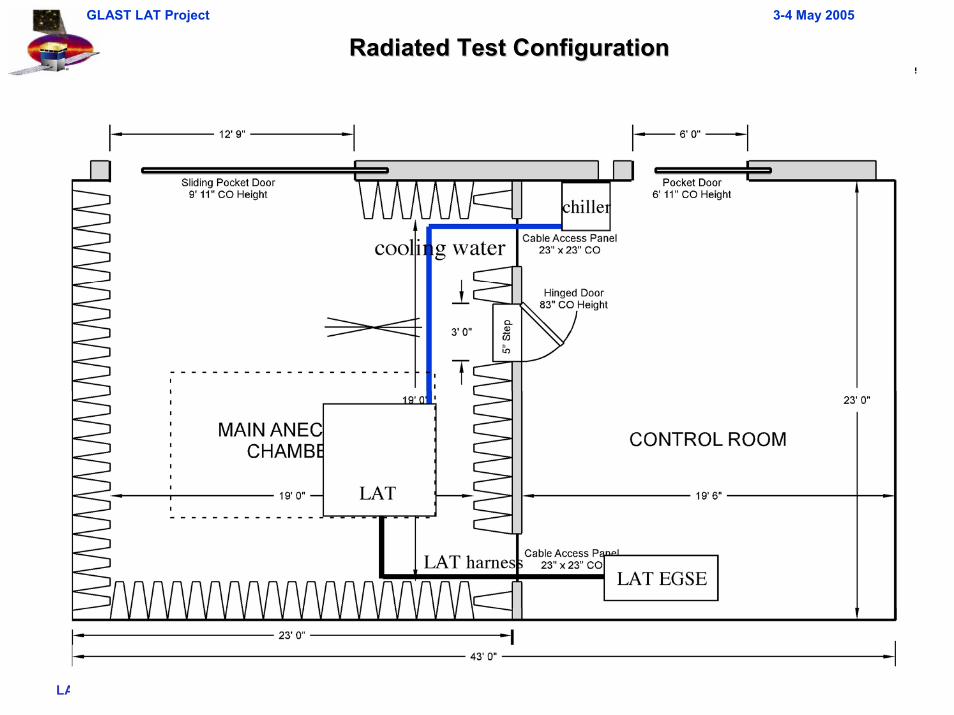
Radiated Test ConfigurationRadiated Test Configuration

LAT Environmental Test PDR 8
GLAST LAT Project 3-4 May 2005
MGSE/STE for EMI/EMC TestingMGSE/STE for EMI/EMC Testing
• LAT (on the TIP) is mounted on the Test Stand for EMI/EMC testing
– LAT + TIP mounts to Test Stand– Radiators are not yet integrated for this
test, since they are not part of the EMI/EMC Test Plan
– LAT is rolled into the anechoic chamber– Dust Tent remains over the LAT for the
entire operation, including during testing
• Auxiliary cooling is needed during the test, since the LAT will be on for the entire test duration
Test Interface Plate
LAT
Test StandRadiators not yet integrated for this test
EMI/EMC Test ConfigurationEMI/EMC Test Configuration

LAT Environmental Test PDR 9
GLAST LAT Project 3-4 May 2005
LAT Radiated Test ConfigurationLAT Radiated Test Configuration

LAT Environmental Test PDR 10
GLAST LAT Project 3-4 May 2005
MGSE Requirements Flowing from EMI/EMC Test PlansMGSE Requirements Flowing from EMI/EMC Test Plans
• See the table, below, for a list of all MGSE/STE that is needed for conducting the EMI/EMC test• Test Stand
– Provides clear access around the perimeter of the LAT for positioning antennae during the test
– Provides clear access directly under the LAT for positioning an antenna• Dust Tent
– Capable of providing clean, dry environment before/during/after EMI/EMC testing– Provides clearance around LAT– Does not impact the radiated emissions or susceptibility tests (must be essentially
transparent to EM radiation in frequency range of tests)• Chill Bars and Auxiliary Cooling system
– Operated during the test
MGSE Assembly Use / CommentsTest Interface Plate Ass'y Mounts LAT to slip table/expander headTest Stand Use with casters/jacks to move into chamberDust Tent Covers LAT in un-regulated environmentChill Bars and Aux. Cooling Cool LAT for pre-/post-test LPT's
MGSE/STE Needed for EMI/EMC TestingMGSE/STE Needed for EMI/EMC Testing
LAT Environmental Test PDR 11
GLAST LAT Project 3-4 May 2005
Auxiliary Cooling and Mechanical HandlingAuxiliary Cooling and Mechanical Handling
• Auxiliary cooling plans– LAT needs to be cooled during the entire duration of EMI/EMC testing
• Chill Bars: one under each of the two X-wings on the Grid• X-LAT Aux Cooling: using fly-away cooling lines already mounted to X-LAT Plate
– This is room-temperature cooling to remove LAT process heat– Fluorinert FC-77 working fluid is a dielectric, and hoses are non-conducting, so the
chiller system will be electrically isolated from the LAT• Handling and mechanical operating procedures
– LAT lifting procedure– Test Stand handling and operating procedure– Dust tent handling and operating procedure– LAT auxiliary cooling system operating procedure
LAT Environmental Test PDR 12
GLAST LAT Project 3-4 May 2005
MGSE Issues for EMI/EMC TestingMGSE Issues for EMI/EMC Testing
• Dust Tent– This is needed for EMI/EMC testing, because of the dirty conditions outside the test cell,
and the potential for particulates to rain off the overhead anachoic foam– Dust tent will need to be designed to be essentially transparent to EM radiation in
frequency range of tests• Transportation issues
– The EMI/EMC chamber is a long way from our high-bay “home base”• Transportation route is circuitous and floor surfaces are of varying quality
– Need to load-test a wooden trestle over abandoned railroad tracks– We plan to pathfind this route to ensure there are no problems in maneuvering the LAT
– The EMI/EMC chamber has a ¾” door sill/threshold• We plan to build a ramp to roll up and over the sill• This will definitely by prototyped with the pathfinder, since the LAT c.g. is moderately high
LAT Environmental Test PDR 13
GLAST LAT Project 3-4 May 2005
Conducted Test ConsiderationsConducted Test Considerations
• Fully test:– SC PRU (P) - LAT PDU– SC PRU (P) - LAT SIU (P)
• Limited test:– SC PRU (R) - LAT PDU– SC PRU (R) - LAT SIU (R)
• Conducted susceptibility tests may require changing bus protection unit settings

LAT Environmental Test PDR 14
GLAST LAT Project 3-4 May 2005
Conducted Test HarnessConducted Test Harness
• Require access to power harness ~2 m from LAT I/F– CE102, CS102 (10kHz - 150kHz), CSCM (30Hz - 150kHz), CECM– All conductors of power circuit must be connected to a single 1/4” lug on line conditioner– All conductors must be gathered into a bundle so that a current probe may be connected
around them
• Require access to power harness ~5cm for LAT I/F– CS102 (150kHz - 150MHz), CS06, CSCM (150kHz - 150MHz)– Small bare section of a single conductor to attach clip lead for hf injection
• EMI shielding not required on breakout harnesses
• Harness specification in work– See R. Bielawski talk
LAT Environmental Test PDR 15
GLAST LAT Project 3-4 May 2005
Radiated Test HarnessRadiated Test Harness
• No access to conductors required
• Harness must be fully shielded– Includes all connector savers
• Any test ports must be closed out or have shielded harnesses– “back door”
• Test harnesses must be shielded – Accelerometers– TCs & thermistors
• Harness supports not directly connected to the LAT should be nonconducting material, wood or PVC
LAT Environmental Test PDR 16
GLAST LAT Project 3-4 May 2005
GroundingGrounding
• All LAT EGSE must be capable of ≤2.5mOhm connection to facility ground– BPU– VSC– Computers
• Chiller must be connected to LAT via nonconducting tubing– Chiller chassis must be capable of ≤2.5mOhm connection to facility ground
• LAT and or LAT MGSE must have ground points on all four sides capable of ≤2.5mOhm connection to facility ground
– To obtain grid to ground ≤2.5mOhm

LAT Environmental Test PDR 17
GLAST LAT Project 3-4 May 2005
Test SoftwareTest Software
• Emissions Testing– Utilize the FSW Charge Injection Calibration function to inject charge into a large number
of detectors. The number of channels into which charge can be injected will be limited by: a) FSW design (which is not yet complete); and b) The number of channels which can physically be injected with charge in any given one second cycle. The one second cycle is required to provide repeatability during the Emissions frequency sweeps.
• Susceptibility Testing:– A variation of the test described in the End-to-End (ETE) Test Plan, LAT-MD-03489,
paragraph 2.2.1, item 4, "Nominal Rate Cosmic Ray Test" will be used. This test is run at ambient temperature and at nominal voltage, timing, threshold, and trigger configurations. Both Cosmics and the external trigger function are used to create on-orbit trigger rates. The external trigger rate will be set so that the total trigger rate will be at or near the nominal expected on-orbit values.
– The externally triggered events should have very low occupancy, monitor to see if occupancy goes up
– The cosmic ray events should remain constant, monitor to see if rate goes up.
– Need real time continuous go/no go
LAT Environmental Test PDR 18
GLAST LAT Project 3-4 May 2005
Test EGSE Software ToolsTest EGSE Software Tools
• Displays of natural trigger rates and occupancy of externally triggered events should be strip chart type
• Other error status, checksum, etc. should latch

LAT Environmental Test PDR 19
GLAST LAT Project 3-4 May 2005
RE101 RE101 –– All LAT EquipmentAll LAT Equipment
40
50
60
70
80
90
100
110
120
130
1.E+01 1.E+02 1.E+03 1.E+04 1.E+05
Frequency (Hz)
Mag
netic
Fie
ld (d
BpT
)
(20, 120)
(50K, 52)
LAT Environmental Test PDR 20
GLAST LAT Project 3-4 May 2005
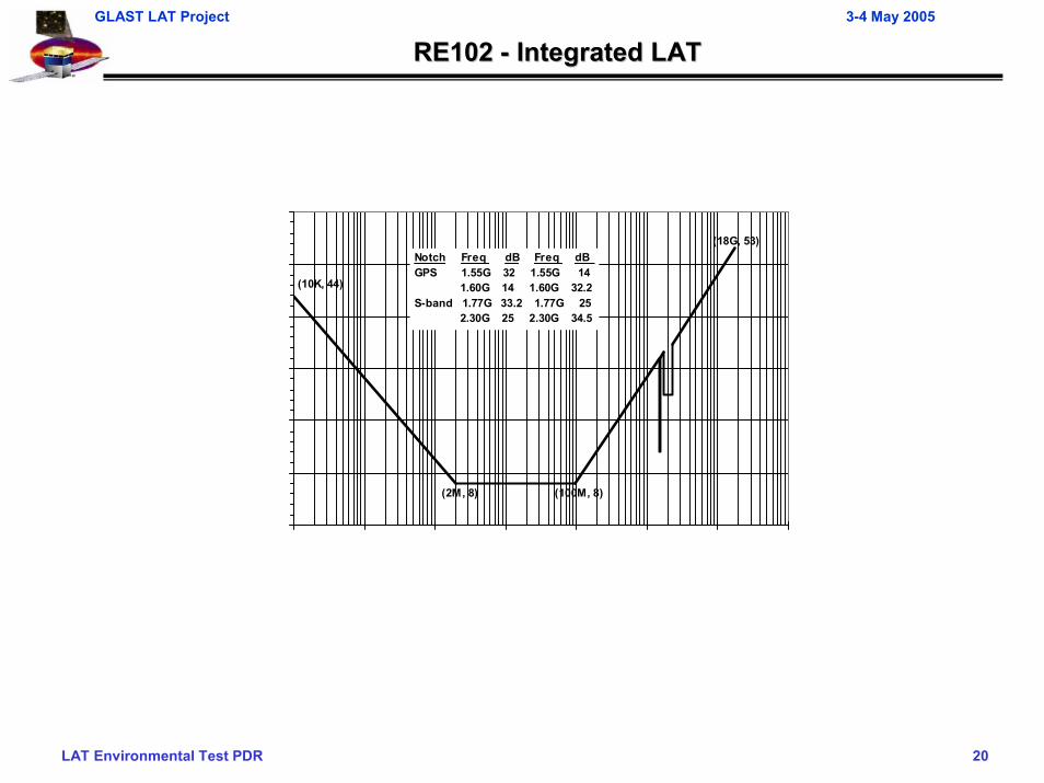
RE102 RE102 -- Integrated LATIntegrated LAT
Notch Freq dB Freq dB GPS 1.55G 32 1.55G 14 1.60G 14 1.60G 32.2S-band 1.77G 33.2 1.77G 25 2.30G 25 2.30G 34.5
(10K, 44)
(18G, 53)
(2M, 8) (100M, 8)

LAT Environmental Test PDR 21
GLAST LAT Project 3-4 May 2005
CE102 CE102 SpacecraftSpacecraft PRU PRU –– LAT DAQLAT DAQ
50
60
70
80
90
1.E+03 1.E+04 1.E+05 1.E+06 1.E+07 1.E+08
Frequency (Hz)
Lim
it Le
vel
(dB
uA)
(350K,80)
(10M,60)
(10K,80)
(1.7M, 82)
(5.5M, 60)
(450K, 86) (1M, 86)
LAT Environmental Test PDR 22
GLAST LAT Project 3-4 May 2005
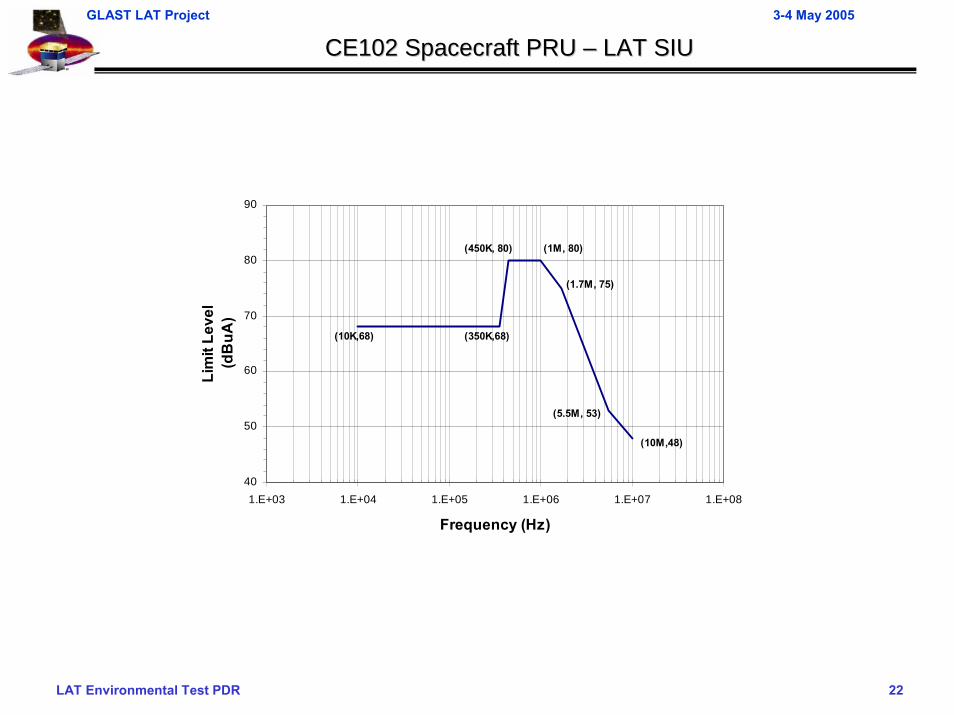
CE102 CE102 SpacecraftSpacecraft PRU PRU –– LAT SIULAT SIU
40
50
60
70
80
90
1.E+03 1.E+04 1.E+05 1.E+06 1.E+07 1.E+08
Frequency (Hz)
Lim
it Le
vel
(dB
uA)
(350K,68)
(10M,48)
(10K,68)
(1.7M, 75)
(5.5M, 53)
(450K, 80) (1M, 80)
LAT Environmental Test PDR 23
GLAST LAT Project 3-4 May 2005
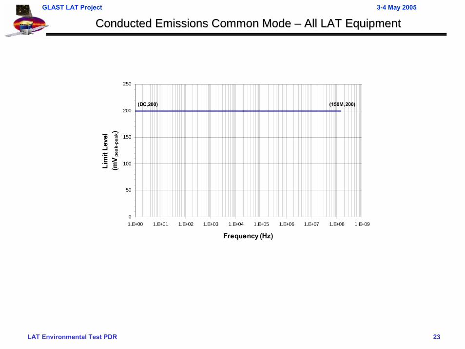
Conducted Emissions Common Mode Conducted Emissions Common Mode –– All LAT EquipmentAll LAT Equipment
0
50
100
150
200
250
1.E+00 1.E+01 1.E+02 1.E+03 1.E+04 1.E+05 1.E+06 1.E+07 1.E+08 1.E+09
Frequency (Hz)
Lim
it Le
vel
(mV
peak
-pea
k)(DC,200) (150M,200)
LAT Environmental Test PDR 24
GLAST LAT Project 3-4 May 2005
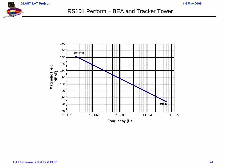
RS101 Perform RS101 Perform –– BEA and Tracker TowerBEA and Tracker Tower
60
70
80
90
100
110
120
130
140
150
160
1.E+01 1.E+02 1.E+03 1.E+04 1.E+05
Frequency (Hz)
Mag
netic
Fie
ld (d
BpT
)(20, 142)
(50K,76)
LAT Environmental Test PDR 25
GLAST LAT Project 3-4 May 2005
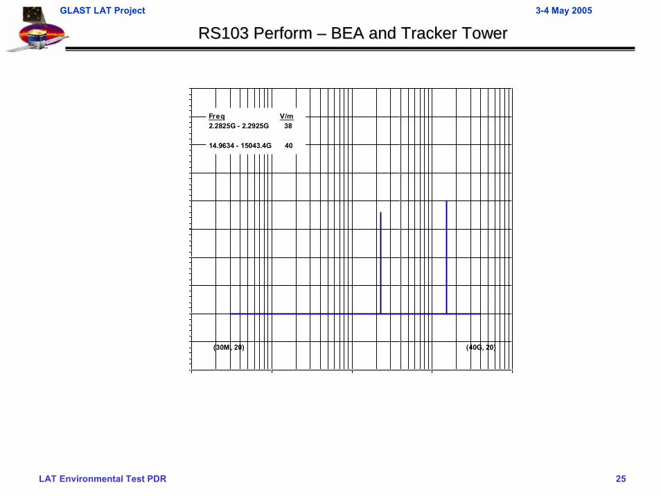
RS103 Perform RS103 Perform –– BEA and Tracker TowerBEA and Tracker Tower
(40G, 20)(30M, 20)
Freq V/m2.2825G - 2.2925G 38
14.9634 - 15043.4G 40

LAT Environmental Test PDR 26
GLAST LAT Project 3-4 May 2005
CS102 CS102 SpacecraftSpacecraft PRU PRU –– LAT DAQLAT DAQ
50
60
70
80
90
1.E+03 1.E+04 1.E+05 1.E+06 1.E+07 1.E+08
Frequency (Hz)
Lim
it Le
vel
(dB
uA)
(350K, 74)
(10M, 54)
(10K, 74)
(1.7M, 81)
(5.5M, 59)
(450K, 86) (1M, 86)

LAT Environmental Test PDR 27
GLAST LAT Project 3-4 May 2005
CS102 CS102 SpacecraftSpacecraft PRU PRU –– LAT SIULAT SIU
50
60
70
80
90
1.E+03 1.E+04 1.E+05 1.E+06 1.E+07 1.E+08
Frequency (Hz)
Lim
it Le
vel
(dB
uA)
(350K, 74)
(10M, 54)
(10K, 74)
(1.7M, 81)
(5.5M, 59)
(450K, 86) (1M, 86)
LAT Environmental Test PDR 28
GLAST LAT Project 3-4 May 2005
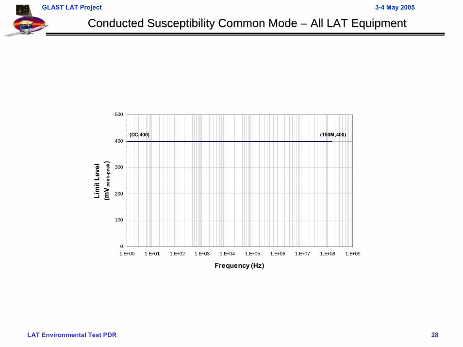
Conducted Susceptibility Common Mode Conducted Susceptibility Common Mode –– All LAT EquipmentAll LAT Equipment
0
100
200
300
400
500
1.E+00 1.E+01 1.E+02 1.E+03 1.E+04 1.E+05 1.E+06 1.E+07 1.E+08 1.E+09
Frequency (Hz)
Lim
it Le
vel
(mV
peak
-pea
k)
(DC,400) (150M,400)
LAT Environmental Test PDR 29
GLAST LAT Project 3-4 May 2005
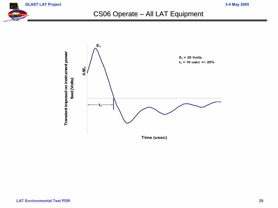
CS06 Operate CS06 Operate –– All LAT EquipmentAll LAT Equipment
Time (usec)
Tran
sien
t im
pose
d on
inst
rum
ent p
ower
fe
ed (V
olts
)
t1
E1
0.5E
1
E1 = 20 Voltst1 = 10 usec +/- 20%
LAT Environmental Test PDR 30
GLAST LAT Project 3-4 May 2005
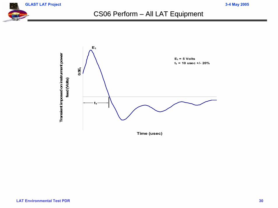
CS06 Perform CS06 Perform –– All LAT EquipmentAll LAT Equipment
Time (usec)
Tran
sien
t im
pose
d on
inst
rum
ent p
ower
fe
ed (V
olts
)
t1
E1
0.5E
1
E1 = 5 Voltst1 = 10 usec +/- 20%
LAT Environmental Test PDR 31
GLAST LAT Project 3-4 May 2005
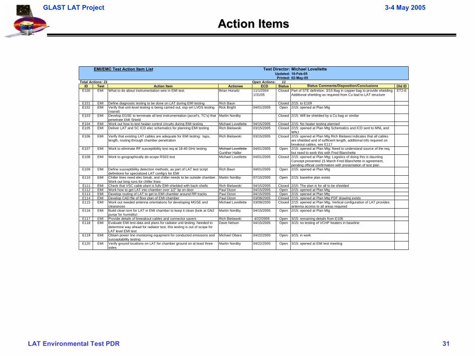
Action ItemsAction Items
EMI/EMC Test Action Item List Test Director: Michael LovelletteUpdated: 18-Feb-05Printed: 02-May-05
Total Actions: 21 Open Actions: 11ID Test Action Item Actionee ECD Status Status Comments/Disposition/Conclusions Old ID
E100 EMI What to do about instrumentation wire in EMI test. Brian Horwitz 11/1/20041/31/05
Closed Part of STE definition. 3/15 Bag in copper bag to provide shielding. Additional shielding as required from Cu bad to LAT structure
ET2-8
E101 EMI Define diagnostic testing to be done on LAT during EMI testing Rich Baun Closed 2/15: to E109E102 EMI Verify that unit-level testing is being carried out, esp wrt LVDS testing
(signal)Rick Bright 04/01/2005 Open 2/15: opened at Plan Mtg
E103 EMI Develop EGSE to terminate all test instrumentation (accel's, TC's) that penetrate EMI Shield
Martin Nordby Closed 2/15: Will be shielded by a Cu bag or similar
E104 EMI Work out how to test heater control circuits during EMI testing Michael Lovellette 04/15/2005 Closed 2/15: No heater testing plannedE105 EMI Deliver LAT and SC ICD elec schematics for planning EMI testing Rich Bielawski 03/15/2005 Closed 2/15: opened at Plan Mtg Schematics and ICD sent to MNL and
WNJE106 EMI Verify that existing LAT cables are adequate for EMI testing: taps,
length, routing through chamber penetrationRich Bielawski 03/15/2005 Closed 2/15: opened at Plan Mtg Rich Bielawsi indicates that all cables
are shielded and of sufficient length, additional info required on breakout cables, see E117
E107 EMI Work to eliminate RF susceptibility test req at 18-40 GHz testing Michael Lovellette Gunther Haller
04/01/2005 Open 2/15: opened at Plan Mtg; Need to understand source of the req, but need to work this with Fred Blanchette
E108 EMI Work to geographically de-scope RS03 test Michael Lovellette 04/01/2005 Closed 2/15: opened at Plan Mtg; Logistics of doing this is daunting Concept presented 15 March Fred Blanchette in agreement, pending official confirmation with presentation of test plan
E109 EMI Define susceptibility detection methods, as part of LAT test script definitions for specialized LAT config's for EMI
Rich Baun 04/01/2005 Open 2/15: opened at Plan Mtg
E110 EMI Chiller lines need elec break, and chiller needs to be outside chamber. Work out long runs for chiller lines
Martin Nordby 07/15/2005 Open 2/15: baseline plan exists
E111 EMI Check that VSC cable plant is fully EMI-shielded with back-shells Rich Bielawski 04/15/2005 Closed 2/15: The plan is for all to be shieldedE112 EMI Work how to get LAT into chamber over 1/2" lip on door Paul Dizon 04/15/2005 Open 2/15: opened at Plan MtgE113 EMI Develop routing of LAT to get to EMI chamber around RR tracks Paul Dizon 04/15/2005 Open 2/15: opened at Plan MtgE114 EMI Develop CAD file of floor plan of EMI chamber Paul Dizon 03/08/2005 Closed 2/15: opened at Plan Mtg PDF drawing existsE115 EMI Work out needed antenna orientations for developing MGSE and
clearancesMichael Lovellette 03/08/2005 Closed 2/15: opened at Plan Mtg, Vertical configuration of LAT provides
antenna access to all areas requiredE116 EMI Build clean tent for LAT in EMI chamber to keep it clean (look at GN2
purge for humidity)Martin Nordby 04/15/2005 Open 2/15: opened at Plan Mtg
E117 EMI Provide details of breeakout cables and connector savers Rich Bielawski 4/22/2005 Open 3/15: remaining details from E106E118 EMI Evaluate EMI test data and plans for radiator unit testing. Needed to
determine way ahead for radiator test, this testing is out of scope for LAT level EMI test
Dave Nelson 04/15/2005 Open 3/15: no testing of VCHP heaters in baseline
E119 EMI Obtain power line monitoring equipment for conducted emissions and susceptability testing
Michael Obara 04/22/2005 Open 3/15: in work
E120 EMI Verify ground locations on LAT for chamber ground on at least three sides
Martin Nordby 04/22/2005 Open 3/15: opened at EMI test meeting