Embed Size (px)
Citation preview

University of Florida EML4140 §5964 Spring 2008
http://www.mae.ufl.edu/courses/spring2008/eml4140
EML4140 HEAT TRANSFER NOTES

EML 4140 Heat Transfer – Spring 2008
Instructor: Dr. Subrata Roy Associate Professor, Department of Mechanical and Aerospace Engineering
Office: 336 MAE-B Phone: 392-9823: E-mail: [email protected]
Office Hours: M W 1:30 to 2:30 PM Generally briefly available after class, and by appointment at other times.
No assistance with homework after office hours on the day that homework is due. No homework assistance by e-mail.
Teaching Assistants: Ankush Bhatia ([email protected]), Patricia Soupy Dalyander ([email protected])
Office hours: M T W R F 9-11 AM Room 126 MAE-C
Required Text: Fundamentals of Heat and Mass Transfer, F.P. Incropera and D.P. DeWitt,
6th Edition (John Wiley & Sons, 2007)
Course Website: http://www.mae.ufl.edu/courses/spring2008/eml4140
Prereq: CGS 2425, EML 3100, EGM 4313
Meeting Time & Place: M W F, 5th Period in NEB Rm. 100
Course Objectives and Outcomes: This course provides a intermediate level coverage of thermal transport processes via conduction, convection, and radiation heat transfer. This course stresses fundamental engineering science principles applied to engineering thermal analysis. Students will learn to apply the conservation of energy to control volumes and express the conservation of energy through mathematical formulations, including both steady state and transient analyses, with emphasis on the fundamental physics and underlying mathematics associated with heat transfer. Upon completion of this course, students are expected to understand basic heat transfer problem formulation and solution techniques, coupled with a strong foundation and appreciation for the physics of heat transfer.
Program Objectives and Outcomes: EML 4140 supports several educational objectives enumerated in the Mission Statement of the Department of Mechanical and Aerospace Engineering. Specific objectives supported by this course include: 1) To understand and perform engineering analyses in the area of thermal systems, 2) To comprehend quantitative, analytical, and experimental methods, 3) To acquire the knowledge base, confidence, and mental discipline for self-education and a lifetime of learning.

Catalog Description: Credits: 3; Steady state and transient analysis of conduction and radiation heat transfer in stationary media. Heat transfer in fluid systems, including forced and free convection.
Contribution of course to meeting the ABET professional component:4A. EML 4140 supports several program outcomes enumerated in the Mission Statement of the
Department of Mechanical and Aerospace Engineering. Specific ME program outcomes supported by this course include:(1) Using knowledge of chemistry and calculus based physics with depth in at least one of them (ME Program Outcome M1);(2) Using knowledge of advanced mathematics through multivariate calculus and differential equations (ME Program Outcome M2);(3) Being able to work professionally in the thermal systems area (ME Program Outcome M4).
4B. Mathematical Sciences (15%), Physical Sciences (15%), Engineering Sciences (70%).
Relationship of course to ABET program outcomes:This course achieves the following ABET outcomes. Note that the outcome number corresponds
to the respective ABET outcomes (a) through (k).
(a) Apply knowledge of mathematics, science, and engineering: Outcome (a), method of assessment is specially selected problems on three exams and homework.
(e) Identify, formulate, and solve engineering problems: Outcome (e), method of assessment is specially selected problems on three exams and homework.
(i) Recognize the need for, and engage in life long learning: Outcome (i), method of assessment is several critiques of research papers in the field of Heat Transfer and critiquing professional seminars in Heat Transfer.
(k) Use the techniques, skills, and modern engineering tools necessary for engineering practice: Outcome (k), method of assessment is specially selected problems on three exams and homework.

Course Outline:
First unit: 5 Weeks 1. Introduction to heat transfer and rate laws2. Fourier’s Law and heat diffusion equation3. Rate equations and conservation of energy4. Introduction to conduction 5. One-dimensional steady-state conduction (planar and cylindrical)6. Contact resistance and thermal circuits7. Heat transfer from extended surfaces8. Two-dimensional steady state heat transfer: Finite difference method9. Energy Balance method for nodal equations and boundary nodes
10. Transient conduction, lumped capacitance method 11. Transient conduction, exact solutions and Heisler Charts
Reading material:1. Chapters 1 and 2 2. Chapter 3 (omit 3.2) 3. Chapter 4 (omit 4.2, 4.3, 4.5) 4. Chapter 5 (omit 5.8, 5.9)
Second unit: 5 Weeks
1. Introduction to convective transport processes2. Introduction to boundary layers3. Convective transport equations in differential form4. Dimensionless variables and Reynolds analogy5. Effects of turbulence6. Introduction to external flow heat transfer7. External flow heat transfer correlations8. Introduction to internal flow heat transfer9. Internal flow heat transfer coefficient and correlations10. Introduction to natural convection11. Introduction to phase change heat transfer
Reading material:1. Chapter 6 (omit 6.7 and 6.8) 2. Chapter 7 (omit 7.5 through 7.8) 3. Chapter 8 (omit 8.6 through 8.9) 4. Chapter 9 (9.1 - 9.3, 9.5, 9.6.1) 5. Chapter 10 (10.1 - 10.3, 10.6)
Third unit: 4 Weeks1. Introduction to radiation heat transfer exchange2. Geometry, radiation intensity, emissive power3. Irradiation and radiosity4. Blackbody radiation exchange5. Band emission

6. Emissivity, reflectivity, absorptivity, transmissivity7. Kirchoff’s Laws8. Radiation view factors9. Net radiation exchange among surfaces10. Black body surfaces11. Gray-Diffuse surfaces
Reading material:1. Chapter 12 2. Chapter 13 (omit 13.4 and 13.5)
Homework Schedule: (due in one week at beginning of the class lecture)
Pretest (not included in the final grade)
1. January 16 – 1.11, 1.18, 1.31, 1.39, 1.46, 1.68 (due Jan 23) 2. January 23 – 2.1, 2.2, 2.4, 2.11, 2.26, 3.9, 3.15 (due Jan 30) 3. January 30 – 3.27, 3.41, 3.52, 3.79, 3.103, 3.112 (due Feb 6) 4. February 6 – 3.130, 3.134, 4.32, 4.38, 4.45, 4.51 (due Feb 13)
Not for submission problems (5.5, 5.8, 5.11, 5.24, 5.40)5. February 20 – TBA (due Feb 27) 6. February 27 – TBA (due Mar 5) 7. March 5 – TBA (due Mar 11) 8. March 19 – TBA (due Mar 26)
Not for submission problems (TBA) 9. April 2 – TBA (due Apr 9)10. April 9 – TBA (due Apr 16)
Not for submission problems (TBA)
Answers to End-of-Chapter Problems
Selected answers
Examination Schedule:
1. Exam I on Monday, February 11 (Summary)2. Exam II on Monday, March 24 (Summary)3. Exam III on Monday, April 21 (Summary)4. Final Exam on Wednesday, April 30 from 5:30 PM to 7:30 PM (Fall’07 Final
Grade Summary)
5. All exams are closed book. For the first 3 exams, you may bring in two sheets of paper (8.5” x 11.5”) with whatever notes you want on both the front and back. On the final exam, you may bring six sheets of paper with notes on the front and back. (Sample problems are highlighted in red in HWs above. Also study any conceptual questions/graphs. This is just a non-binding guide line.)
You should bring a calculator for all exams.

Course Grading: 1. Grading basis: Homework 10% 3 1-hour Exams 60% (20% each) Project 10% Final Exam 20% Total 100%
2. Homework: Ten homework assignments total. Homework is due at beginning of the lecture on the assigned due date. Randomly selected problem(s) will be graded. Final homework grade equals the lesser of 100% or ( HWi )/9, for i =1 to 10. Show all
work, clearly mark answers, and be neat.
3. Group Project: A list of challenge problems will be assigned in the 11th week. A group may have between 3-5 students from the class. A typed final project report is due at the beginning of the last class lecture. Projects will be evaluated as a group task. The following sections are expected in the final report: An Abstract describing the summary of the report, an Introduction of the project problem, a description of the Approach, all Design Calculations including figures and photographs, a section describing Concluding Remarks, all References including internet websites, and a paragraph describing the Learning Process from this project. The report should not exceed 8 printed pages.
4. Final Exam will be comprehensive.
5. Grading Scale: The standard deviation of your four test scores may be added to your lowest test score. Alternatively, I may give you a chance to redo tests (except the final) for earning back a percentage of what you missed. This will be done at my discretion. A 10-point scale (i.e. A>90%, B>80%, etc.) will be used as a baseline for final grades. An additional curve may be applied, as determined by the overall finalgrade distribution of the class. Grades of B+, C+, etc. will be determined at my discretion and are not based on a 5-point scale (e.g. 85%).
Class Policies:
1. Regular class attendance is expected and encouraged. Each student is responsible for all of the material presented in class and in the reading assignments. Exams will emphasize treatment of material covered in lectures.
2. All homework assignments and projects are to be turned in at the beginning of the designated class period. In general, no late assignments will be accepted or makeup exams given. Exceptions will be made for a valid excuse consistent with University Policy. Exceptions may also be made if deemed appropriate, but please contact me ahead of time.
3. SOME collaboration is allowable on homework, but each student is responsible for

performing the bulk of his or her own homework assignment. The copying of solutions from the Solutions Manual (or copies from) is considered cheating, and is not allowed.
4. NO collaboration is allowed on exams.
5. Honesty Policy – All students admitted to the University of Florida have signed a statement of academic honesty committing themselves to be honest in all academic work and understanding that failure to comply with this commitment will result in disciplinary action. This statement is a reminder to uphold your obligation as a UF student and to be honest in all work submitted and exams taken in this course and all others.
6. Accommodation for Students with Disabilities – Students Requesting classroom accommodation must first register with the Dean of Students Office. That office will provide the student with documentation that he/she must provide to the course instructor when requesting accommodation. This process must be completed in advance.
7. UF Counseling Services – Resources are available on-campus for students having personal problems or lacking clear career and academic goals. The resources include:University Counseling Center, 301 Peabody Hall, 392-1575; SHCC Mental Health, Student Health Care Center, 392-1171; Center for Sexual Assault/Abuse Recovery and Education (CARE), Student Health Care Center, 392-1161. Career Resource Center, Reitz Union, 392-1601, for career development assistance and counseling.
8. Software Use – All faculty, staff and student of the University are required and expected to obey the laws and legal agreements governing software use. Failure to do so can lead to monetary damages and/or criminal penalties for the individual violator.Because such violations are also against University policies and rules, disciplinary action will be taken as appropriate. We, the members of the University of Florida community, pledge to uphold ourselves and our peers to the highest standards of honesty and integrity.


University of Florida EML4140 §5964 Spring 2008
http://www.mae.ufl.edu/courses/spring2008/eml4140
EML4140 HEAT TRANSFER BLOCK I CONDUCTION
Page 1 of 167

Heat Transfer: Physical Origins
andRate Equations
Chapter OneSections 1.1 and 1.2
Heat Transfer and Thermal Energy
• What is heat transfer?
• What is thermal energy?
Thermal energy is associated with the translation, rotation,vibration and electronic states of the atoms and moleculesthat comprise matter. It represents the cumulative effect ofmicroscopic activities and is directly linked to the temperatureof matter.
Heat transfer is thermal energy in transit due to a temperaturedifference.
Page 2 of 167

Heat Transfer and Thermal Energy (cont.)
UnitsSymbolMeaningQuantity
Energy associated with microscopic behavior of matter
Thermal Energy+
A means of indirectly assessing the amount of thermal energy stored in matter
Temperature
Thermal energy transport due to temperature gradients
Heat Transfer
Amount of thermal energy transferred over a time interval t 0
Heat
Thermal energy transfer per unit timeHeat Rate
Thermal energy transfer per unit time and surface area
Heat Flux
or U u J or J/kg
T K or °C
Q J
q W
q 2W/m
+
Thermal energy of system
Thermal energy per unit mass of system
U
u
DO NOT confuse or interchange the meanings of ThermalEnergy, Temperature and Heat Transfer
Modes of Heat Transfer
Conduction: Heat transfer in a solid or a stationary fluid (gas or liquid) due to the random motion of its constituent atoms, molecules and /or electrons.
Convection: Heat transfer due to the combined influence of bulk and random motion for fluid flow over a surface.
Radiation: Energy that is emitted by matter due to changes in the electron configurations of its atoms or molecules and is transported as electromagnetic waves (or photons).
• Conduction and convection require the presence of temperature variationsin a material medium.
• Although radiation originates from matter, its transport does not require a material medium and occurs most efficiently in a vacuum.
Modes of Heat Transfer
Page 3 of 167

Heat Transfer Rates: Conduction
Conduction:
General (vector) form of Fourier’s Law:
1 2x
T Tq k
L(1.2)
Heat rate (W):
x xq q A
Application to one-dimensional, steady conduction across aplane wall of constant thermal conductivity:
2 1x
T TdTq k k
dx L
q k T
Heat flux Thermal conductivity Temperature gradient2W/m W/m K °C/m or K/m
Heat Transfer Rates
Heat Transfer Rates:Convection
Convection
Relation of convection to flow over a surface and developmentof velocity and thermal boundary layers:
Newton’s law of cooling:
h sq T T (1.3a)
: Convection heat transfer coefficient 2(W/m K)h
Heat Transfer Rates
Page 4 of 167
Heat Transfer Rates: Radiation
Radiation Heat transfer at a gas/surface interface involves radiation emission from the surface and may also involve theabsorption of radiation incident from the surroundings(irradiation, ), as well as convection if .sT T
Energy outflow due to emission:4
b sE E T (1.5)
emissiv: Surface 0ity 1blackbod: Emissive power of a (the perfect emity ter)bE
2Emissive powe: r W/mE
-8 2 4: Stefan-Boltzmann constant 5.67×10 W/m K
Energy absorption due to irradiation:
absG G2: incidAbsorbed radiationent (W/m )absG
absorpti: Surfa vityce 0 12Irradiation: W/mG
G
Heat Transfer Rates
Heat Transfer Rates: Radiation (cont.)
Irradiation: Special case of surface exposed to largesurroundings of uniform temperature, surT
4sur surG G T
4 4
If , the from the
surface due to exchange with the surroundings is:
net radiation heat flux
rad b s s surq E T G T T (1.7)
Heat Transfer Rates
Page 5 of 167

Heat Transfer Rates: Radiation (cont.)
Alternatively,
2
2 2
Radiation heat transfer coefficient
h
h : W/m K
h
rad r s sur
r
r s sur s sur
q T T
T T T T
(1.8)
(1.9)
For combined convection and radiation,
(1.10)h hconv rad s r s surq q q T T T T
Heat Transfer Rates
Problem 1.73(a): Process identification for single-and double-pane windows
Schematic:
Convection from room air to inner surface of first pane,1convq
,1radq Net radiation exchange between room walls and inner surface of first pane
,1condq Conduction through first pane
,conv sq
,rad sqConvection across airspace between panes
Net radiation exchange between outer surface of first pane and inner surface of second pane (across airspace)
,2condq Conduction through a second pane
,2radq
,2convq Convection from outer surface of single (or second) pane to ambient air
Net radiation exchange between outer surface of single (or second) pane and surroundings such as the ground
Sq Incident solar radiation during day; fraction transmitted to room is smaller for double pane
Process Identification
Page 6 of 167

Problem 1.31: Power dissipation from chips operating at a surface temperatureof 85 C and in an enclosure whose walls and air are at 25 C for (a) free convection and (b) forced convection.
Schematic:
Assumptions: (1) Steady-state conditions, (2) Radiation exchange between a small surface and a large enclosure, (3)Negligible heat transfer from sides of chip or from back of chip by conduction through the substrate.
Analysis:
elec conv radP q q
(a) If heat transfer is by natural convection,
5 / 4 5/42 5/4 -4 2
-4 2 -8 2 4 4 4 4
4.2W/m K 2.25×10 m 60K =0.158W
0.60 2.25×10 m 5.67×10 W/m K 358 -298 K =0.065W
0.158W+0.065W=0.223W
conv s
rad
elec
q CA T T
q
P
(b) If heat transfer is by forced convection,2 4 -4 2h 250W/m K 2.25×10 m 60K =3.375W
3.375W+0.065W=3.44W
conv s
elec
q A T T
P
4 4h s s surA T T T T22 -4 20.015m =2.25×10 mA L
Problem: Electronic Cooling
Fourier’s Lawand the
Heat Equation
Chapter Two
Page 7 of 167
Fourier’s Law
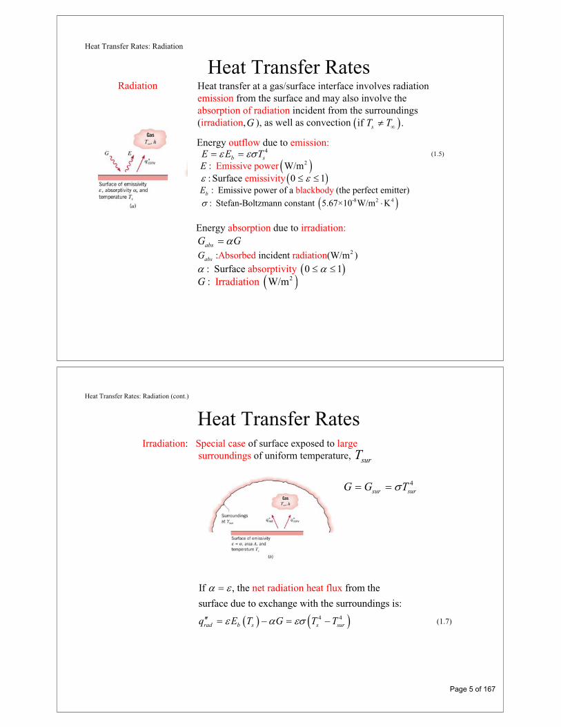
• A rate equation that allows determination of the conduction heat fluxfrom knowledge of the temperature distribution in a medium
Fourier’s Law
• Its most general (vector) form for multidimensional conduction is:
q k T
Implications:– Heat transfer is in the direction of decreasing temperature
(basis for minus sign).
– Direction of heat transfer is perpendicular to lines of constant temperature (isotherms).
– Heat flux vector may be resolved into orthogonal components.
– Fourier’s Law serves to define the thermal conductivity of themedium /k q T
Heat Flux Components
(2.22)T T T
q k i k j k kr r z
rq q zq
• Cylindrical Coordinates: , ,T r z
sinT T T
q k i k j k kr r r
(2.25)
rq q q
• Spherical Coordinates: , ,T r
• Cartesian Coordinates: , ,T x y z
T T Tq k i k j k k
x y z
xq yq zq
(2.3)
Page 8 of 167

Heat Flux Components (cont.)
• In angular coordinates , the temperature gradient is stillbased on temperature change over a length scale and hence hasunits of C/m and not C/deg.
or ,
• Heat rate for one-dimensional, radial conduction in a cylinder or sphere:
– Cylinder2r r r rq A q rLq
or,2r r r rq A q rq
– Sphere24r r r rq A q r q
Heat Equation
The Heat Equation• A differential equation whose solution provides the temperature distribution in a
stationary medium.
• Based on applying conservation of energy to a differential control volume through which energy transfer is exclusively by conduction.
• Cartesian Coordinates:
Net transfer of thermal energy into the control volume (inflow-outflow)
pT T T T
k k k q cx x y y z z t
•(2.17)
Thermal energygeneration
Change in thermalenergy storage
Page 9 of 167

Heat Equation (Radial Systems)
21 1
pT T T T
kr k k q cr r r z z tr
•(2.24)
• Spherical Coordinates:
• Cylindrical Coordinates:
22 2 2 2
1 1 1 sinsin sin p
T T T Tkr k k q c
r r tr r r
•(2.27)
Heat Equation (Special Case)
• One-Dimensional Conduction in a Planar Medium with Constant Propertiesand No Generation
2
21T T
tx
thermal diffu osivit f the medy iump
k
c
Page 10 of 167

Boundary Conditions
Boundary and Initial Conditions• For transient conduction, heat equation is first order in time, requiring
specification of an initial temperature distribution: 0, ,0t
T x t T x
• Since heat equation is second order in space, two boundary conditionsmust be specified. Some common cases:
Constant Surface Temperature:
0, sT t T
Constant Heat Flux:
0|x sT
k qx
Applied Flux Insulated Surface
0| 0xT
x
Convection
0| 0,xT
k h T T tx
Properties
Thermophysical PropertiesThermal Conductivity: A measure of a material’s ability to transfer thermal energy by conduction.
Thermal Diffusivity: A measure of a material’s ability to respond to changesin its thermal environment.
Property Tables:Solids: Tables A.1 – A.3Gases: Table A.4Liquids: Tables A.5 – A.7
Page 11 of 167

Properties (Micro- and Nanoscale Effects)
Micro- and Nanoscale Effects• Conduction may be viewed as a consequence of energy carrier (electron or
phonon) motion.
• For the solid state:
• Energy carriers also collide with physical boundaries, affecting their propagation.
External boundaries of a film of material
average energy carrier velocity, c .
13 mfpk Cc
energy carrierspecific heat perunit volume.
mean free path average distancetraveled by an energy carrier beforea collision.
(2.7)
Properties (Micro- and Nanoscale Effects)
For 1
1 2 3
1 3
mfp
x mfp
y mfp
L
k k L
k k L
/ ,/ // /
Grain boundaries within a solid
Measured thermal conductivity of a ceramic material vs. grain size, L. at 300K 25nm.mfp T
• Fourier’s law does not accurately describe the finite energy carrier propagationvelocity. This limitation is not important except in problems involving extremelysmall time scales.
(2.9a)
(2.9b)
Page 12 of 167

Conduction Analysis
Typical Methodology of a Conduction Analysis
• Solve appropriate form of heat equation to obtain the temperaturedistribution.
• Knowing the temperature distribution, apply Fourier’s Law to obtain theheat flux at any time, location and direction of interest.
• Applications:
Chapter 3: One-Dimensional, Steady-State ConductionChapter 4: Two-Dimensional, Steady-State ConductionChapter 5: Transient Conduction
• Consider possible microscale or nanoscale effects in problems involving verysmall physical dimensions or very rapid changes in heating or cooling rates.
Problem : Thermal Response of Plane Wall
Problem 2.46 Thermal response of a plane wall to convection heat transfer.
KNOWN: Plane wall, initially at a uniform temperature, is suddenly exposed to convective heating.
FIND: (a) Differential equation and initial and boundary conditions which may be used to find the temperature distribution, T(x,t); (b) Sketch T(x,t) for the following conditions: initial (t 0), steady-state (t ), and two intermediate times; (c) Sketch heat fluxes as a function of time at the two surfaces; (d) Expression for total energy transferred to wall per unit volume (J/m3).
SCHEMATIC:
Page 13 of 167

Problem: Thermal Response (Cont.)
ASSUMPTIONS: (1) One-dimensional conduction, (2) Constant properties, (3) No internal heat generation.
ANALYSIS: (a) For one-dimensional conduction with constant properties, the heat equation has the form,
2 1T x
T t2
i
0
L
Initial, t 0 : T x,0 T uniform temperature
Boundaries: x=0 T/ x 0 adiabatic surface
x=L k T/ x = h T L,t T surface convection
and the conditions are:
(b) The temperature distributions are shown on the sketch.
Note that the gradient at x = 0 is always zero, since this boundary is adiabatic. Note also that the gradient at x = L decreases with time.
c) The heat flux, q x, txb g, as a function of time, is shown on the sketch for the surfaces x = 0 and x = L.
in conv s0E q A dt
d) The total energy transferred to the wall may be expressed as
in s 0E hA T T L,t dt
Dividing both sides by AsL, the energy transferred per unit volume is
3in0
E h T T L,t dt J/mV L
Problem: Thermal Response (Cont.)
Page 14 of 167

Problem: Non-Uniform Generation due to Radiation Absorption
Problem 2.28 Surface heat fluxes, heat generation and total rate of radiationabsorption in an irradiated semi-transparent material with a prescribed temperature distribution.
KNOWN: Temperature distribution in a semi-transparent medium subjected to radiative flux.
FIND: (a) Expressions for the heat flux at the front and rear surfaces, (b) The heat generation rate ,q xb g and (c) Expression for absorbed radiation per unit surface area.
SCHEMATIC:
Problem: Non-Uniform Generation (Cont.)
ASSUMPTIONS: (1) Steady-state conditions, (2) One-dimensional conduction in medium, (3) Constant properties, (4) All laser irradiation is absorbed and can be characterized by an internal volumetric heat generation term .q xb gANALYSIS: (a) Knowing the temperature distribution, the surface heat fluxes are found using Fourier’s law,
LNMOQPLNM
OQPq k dT
dxk - A
kaa e Bx 2
-axb gFront Surface, x=0:
LNM
OQPLNM
OQPq k + A
kaB A
akBx 0 1b g <
Rear Surface, x=L:LNM
OQPLNM
OQPq L k + A
kae B A
ae kBx
-aL -aLb g . <
(b) The heat diffusion equation for the medium is
ddx
dTdx
qk
or q = -k ddx
dTdx
FHGIKJ
FHGIKJ0
.q x k ddx
Aka
e B Ae-ax -axb g LNM
OQP
(c ) Performing an energy balance on the medium,
E E Ein out g 0
Page 15 of 167

On a unit area basis
Alternatively, evaluate Eg by integration over the volume of the medium,
.z zE q x dx = Ae dx = - Aa
e Aa
eg 0L -ax
0L -ax L -aLb g e j
01
.E E E q q L Aa
eg in out x x-aL0 1b g b g e j
Problem: Non-Uniform Generation (Cont.)
One-Dimensional, Steady-StateConduction without
Thermal Energy Generation
Chapter Three
Sections 3.1 through 3.4
Page 16 of 167

Methodology
• Specify appropriate form of the heat equation.
• Solve for the temperature distribution.
• Apply Fourier’s law to determine the heat flux.
Simplest Case: One-Dimensional, Steady-State Conduction with No
Thermal Energy Generation.
• Common Geometries:
– The Plane Wall: Described in rectangular (x) coordinate. Area
perpendicular to direction of heat transfer is constant (independent of x).
– The Tube Wall: Radial conduction through tube wall.
– The Spherical Shell: Radial conduction through shell wall.
Methodology of a Conduction Analysis
Plane Wall
• Consider a plane wall between two fluids of different temperature:The Plane Wall
• Implications:Heat flux is independent of .xq x
Heat rate is independent of .xq x
• Boundary Conditions: ,1 ,20 , s sT T T L T
• Heat Equation:
0d dT
kdx dx
(3.1)
• Temperature Distribution for Constant :
,1 ,2 ,1s s sx
T x T T TL
(3.3)
k
Page 17 of 167
Plane Wall (cont.)
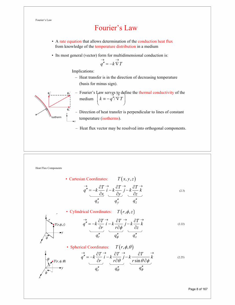
• Heat Flux and Heat Rate:
,1 ,2x s sdT k
q k T Tdx L
(3.5)
,1 ,2x s sdT kA
q kA T Tdx L (3.4)
• Thermal Resistances and Thermal Circuits:tT
Rq
Conduction in a plane wall: ,t condL
RkA
(3.6)
Convection: ,1
t convRhA
(3.9)
Thermal circuit for plane wall with adjoining fluids:
1 2
1 1tot
LR
h A kA h A (3.12)
,1 ,2x
tot
T Tq
R(3.11)
Plane Wall (cont.)
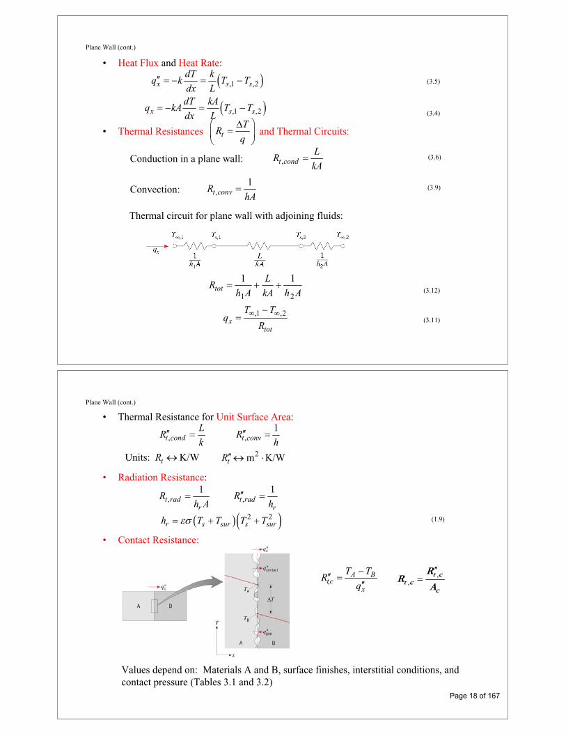
• Thermal Resistance for Unit Surface Area:
,t condL
Rk ,
1t convR
h
Units: K/WtR 2m K/WtR
• Radiation Resistance:
,1
t radr
Rh A ,
1t rad
r
Rh
2 2r s sur s surh T T T T (1.9)
• Contact Resistance:
,A B
tcx
T TR
q,
,t c
t cc
RR
A
Values depend on: Materials A and B, surface finishes, interstitial conditions, and contact pressure (Tables 3.1 and 3.2)
Page 18 of 167

Plane Wall (cont.) • Composite Wall with NegligibleContact Resistance:
,1 ,4x
t
T Tq
R(3.14)
1 4
1 1 1C totA Bt tot
A B C
L RL LR R
A h k k k h A
• Overall Heat Transfer Coefficient (U) :
A modified form of Newton’s Law of Cooling to encompass multiple resistances to heat transfer.
x overallq UA T (3.17)
1totR
UA (3.19)
• Series – Parallel Composite Wall:
Plane Wall (cont.)
• Note departure from one-dimensional conditions for .F Gk k
• Circuits based on assumption of isothermal surfaces normal to x direction or adiabatic surfaces parallel to x direction provide approximations for .xq
Page 19 of 167

Tube Wall
• Heat Equation:
The Tube Wall
10
d dTkr
r dr dr(3.23)
Is the foregoing conclusion consistent with the energy conservation requirement?
How does vary with ?rq r
What does the form of the heat equation tell us about the variation of with
in the wall?rq
r
• Temperature Distribution for Constant :k
,1 ,2,2
1 2 2ln
ln /s s
sT T r
T r Tr r r
(3.26)
Tube Wall (Cont.)
• Heat Flux and Heat Rate:
,1 ,22 1
,1 ,22 1
,1 ,22 1
ln /
22
ln /
22
ln /
r s s
r r s s
r r s s
dT kq k T T
dr r r r
kq rq T T
r r
Lkq rLq T T
r r (3.27)
• Conduction Resistance:2 1
,
2 1,
ln /Units K/W
2ln /
Units m K/W2
t cond
t cond
r rR
Lkr r
Rk
(3.28)
Why doesn’t a surface area appear in the expressions for the thermal resistance?
Page 20 of 167

Tube Wall (Cont.)
• Composite Wall withNegligible Contact
Resistance
,1 ,4,1 ,4r
tot
T Tq UA T T
R(3.30)
1
Note that
is a constant independent of radius.totUA R
But, U itself is tied to specification of an interface.1
i i totU A R (3.32)
Note: For the temperaturedistribution shown, kA > kB > kC.
Spherical Shell
• Heat Equation
Spherical Shell
22
10
d dTr
dr drr
What does the form of the heat equation tell us about the variation ofwith ? Is this result consistent with conservation of energy?rq r
How does vary with ?rq r
• Temperature Distribution for Constant :k
1/,1 ,1 ,2
1 2
1
1 /s s s
r rT r T T T
r r
Page 21 of 167

Spherical Shell (cont.)
• Heat flux, Heat Rate and Thermal Resistance:
,1 ,221 21/ 1/
r s sdT k
q k T Tdr r r r
(3.35)2
,1 ,21 2
44
1/ 1/r r s sk
q r q T Tr r
• Composite Shell:
overallr overall
tot
Tq UA T
R
1 ConstanttotUA R
1Depends on i i tot iU A R A
1 2,
1/ 1/
4t condr r
Rk
(3.36)
Problem: Thermal Barrier Coating
Problem 3.23: Assessment of thermal barrier coating (TBC) for protectionof turbine blades. Determine maximum blade temperaturewith and without TBC.
Schematic:
ASSUMPTIONS: (1) One-dimensional, steady-state conduction in a composite plane wall, (2) Constant properties, (3) Negligible radiation.
Page 22 of 167

Problem: Thermal Barrier (Cont.)
ANALYSIS: For a unit area, the total thermal resistance with the TBC is
1 1, ,tot w o t c iZr InR h L k R L k h
3 4 4 4 3 2 -3 2, 10 3.85 10 10 2 10 2 10 K W =3.69×10 m K Wtot wR m
With a heat flux of
, ,
,
o iw
tot w
T Tq
R
5 2-3 2
1300 K=3.52×10 W m
3.69×10 m K W
the inner and outer surface temperatures of the Inconel are
, ( ) ,s i w i w iT T q h5 2
400 K+ = 1104 K2
3.52×10 W m
500W m K
, ( ) , 1s o w i i wInT T h L k q -3 -4 2 5 2= 400 K+ 2×10 +2×10 m ×K W 3.52×10 W m = 1174 K
Problem: Thermal Barrier (Cont.)
Without the TBC,
1 1 -3 2, 3.20×10 m K Wtot wo o iInR h L k h
1212 Ks,i( wo ) ,i wo iT T q h
, ( ) , 1 1293 Ks o wo i i woInT T h L k q
Use of the TBC facilitates operation of the Inconel below Tmax = 1250 K.
COMMENTS: Since the durability of the TBC decreases with increasing temperature, which increases with increasing thickness, limits to its thickness are associated with reliability considerations.
, , ,wo o i tot woq T T R 4.06 105 W/m2.
the inner and outer surface temperatures of the Inconel are
Page 23 of 167

Problem: Radioactive Waste Decay
SCHEMATIC:
Problem 3.62: Suitability of a composite spherical shell for storingradioactive wastes in oceanic waters.
ASSUMPTIONS: (1) One-dimensional conduction, (2) Steady-state conditions, (3) Constant properties at 300K, (4) Negligible contact resistance.
PROPERTIES: Table A-1, Lead: k = 35.3 W/m K, MP = 601K; St.St.: 15.1 W/m K.
ANALYSIS: From the thermal circuit, it follows that
311
tot
T T 4q= q r
R 3
k = 15.1 W/m·K
Problem: Radioactive Waste Decay (Cont.)
The thermal resistances are:
Pb1 1
R 1/ 4 35.3 W/m K 0.00150 K/W0.25m 0.30m
St.St.1 1
R 1/ 4 15.1 W/m K 0.000567 K/W0.30m 0.31m
2 2 2convR 1/ 4 0.31 m 500 W/m K 0.00166 K/W
totR 0.00372 K/W.
The heat rate is then 35 3q=5 10 W/m 4 / 3 0.25m 32,725 W
and the inner surface temperature is
1 totT T R q=283K+0.00372K/W 32,725 W 405 K < MP = 601K.
Hence, from the thermal standpoint, the proposal is adequate.
COMMENTS: In fabrication, attention should be given to maintaining a good thermal contact. A protective outer coating should be applied to prevent long term corrosion of the stainless steel.
Page 24 of 167

Extended Surfaces
Chapter Three
Section 3.6
Nature and Rationale
Nature and Rationale of Extended Surfaces• An extended surface (also know as a combined conduction-convection system
or a fin) is a solid within which heat transfer by conduction is assumed to be one dimensional, while heat is also transferred by convection (and/orradiation) from the surface in a direction transverse to that of conduction.
– Why is heat transfer by conduction in the x-direction not, in fact, one-dimensional?
– If heat is transferred from the surface to the fluid by convection, what surface condition is dictated by the conservation of energy requirement?
Page 25 of 167

Nature and Rationale (Cont.)
– What is the actual functional dependence of the temperature distribution inthe solid?
– If the temperature distribution is assumed to be one-dimensional, that is,T=T(x) , how should the value of T be interpreted for any x location?
– How does vary with x ?,cond xq
– When may the assumption of one-dimensional conduction be viewed as anexcellent approximation? The thin-fin approximation.
• Extended surfaces may exist in many situations but are commonly used asfins to enhance heat transfer by increasing the surface area available forconvection (and/or radiation). They are particularly beneficial when is small,as for a gas and natural convection.
h
• Some typical fin configurations:
Straight fins of (a) uniform and (b) non-uniform cross sections; (c) annularfin, and (d) pin fin of non-uniform cross section.
Fin Equation
The Fin Equation• Assuming one-dimensional, steady-state conduction in an extended surface
surface of constant conductivity and uniform cross-sectional area ,with negligible generation and radiation , the fin equationis of the form:
k cA
0q•
0radq
2
20
c
d T hPT T
kAdx(3.62)
or, with and the reduced temperature ,2 / cm hP kA T T
22
2 0d mdx
(3.64)
How is the fin equation derived?
Page 26 of 167

Fin Equation
• Solutions (Table 3.4):
Base (x = 0) condition
0 b bT T
Tip ( x = L) conditionsA. : Conve ti |c on / x Lkd dx h LB. : A / |diabati 0c x Ld dx
Fixed temperC. : ature LL
D. (I >2.65): 0nfinite fin mL L
• Fin Heat Rate:
0|ff c x A s
dq kA h x dA
dx
Performance Parameters Fin Performance Parameters• Fin Efficiency:
,max
f ff
f f b
q q
q hA(3.86)
How is the efficiency affected by the thermal conductivity of the fin?Expressions for are provided in Table 3.5 for common geometries.f
1/ 2222 / 2fA w L t
/ 2pA t L
1
0
21
2f
I mL
mL I mL
• Fin Effectiveness:
Consider a triangular fin:
,
ff
c b b
q
hA
• Fin Resistance:
with , and /f ch k A P (3.81)
,1b
t ff f f
Rq hA
(3.92)
Page 27 of 167

Arrays
Fin Arrays• Representative arrays of
(a) rectangular and(b) annular fins.
– Total surface area:t f bA NA A (3.99)
Number of fins Area of exposed base (prime surface)
– Total heat rate:
,
bt f f b b b o t b
t o
q N hA hA hAR
(3.100)
– Overall surface efficiency and resistance:
,1b
t ot o t
Rq hA (3.103)
1 1fo f
t
NA
A(3.102)
Arrays (Cont.)
• Equivalent Thermal Circuit :
• Effect of Surface Contact Resistance:
,
bt t bo c
t o c
q hAR
1
1 1f fo c
t
NA
A C(3.105a)
1 , ,1 /f f t c c bC hA R A (3.105b)
,
1t o c
to c
RhA
(3.104)
Page 28 of 167

Problem: Turbine Blade Cooling
Problem 3.116: Assessment of cooling scheme for gas turbine blade.Determination of whether blade temperatures are lessthan the maximum allowable value (1050 °C) for prescribed operating conditions and evaluation of bladecooling rate.
Assumptions: (1) One-dimensional, steady-state conduction in blade, (2) Constant k, (3)Adiabatic blade tip, (4) Negligible radiation.
Analysis: Conditions in the blade are determined by Case B of Table 3.4.
(a) With the maximum temperature existing at x=L, Eq. 3.75 yields
Schematic:
1coshb
T L T
T T mL1/ 21/ 2 2 -4 2/ 250W/m K×0.11m/20W/m K×6×10 mcm hP kA = 47.87 m-1
mL = 47.87 m-1 0.05 m = 2.39
From Table B.1, . Hence,cosh 5.51mL
and, subject to the assumption of an adiabatic tip, the operating conditions are acceptable.
Eq. 3.76 and Table B.1 yield
Hence,
Comments: Radiation losses from the blade surface contribute to reducing the blade temperatures, but what is the effect of assuming an adiabatic tip condition? Calculatethe tip temperature allowing for convection from the gas.
T L 1200 C (300 1200) C/5.51 1037 C
(b) With 1/ 22 -4 21/ 2 250W/m K×0.11m×20W/m K×6×10 m 900 -517Wc bM hPkA C ,
fq M tanh mL 517W 0.983 508W
b fq q 508W
Problem: Turbine Blade Cooling (cont.)
Page 29 of 167

Problem: Chip Heat Sink
Problem 3.132: Determination of maximum allowable power for a 20mm x 20mm electronic chip whose temperature is not to exceed
when the chip is attached to an air-cooled heat sink with N=11 fins of prescribed dimensions.
cq
85 C,cT
Schematic:
Assumptions: (1) Steady-state, (2) One-dimensional heat transfer, (3) Isothermal chip, (4)Negligible heat transfer from top surface of chip, (5) Negligible temperature rise for air flow,(6) Uniform convection coefficient associated with air flow through channels and over outersurface of heat sink, (7) Negligible radiation.
Analysis: (a) From the thermal circuit,
c cc
tot t,c t,b t,o
T T T Tq
R R R R
2 6 2 2t,c t,cR R / W 2 10 m K / W / 0.02m 0.005 K / W
2t,b bR L / k W W / m K
20.003m /180 0.02m 0.042 K / W
From Eqs. (3.103), (3.102), and (3.99)
ft,o o f t f b
o t t
N A1R , 1 1 , A N A A
h A A
Af = 2WLf = 2 0.02m 0.015m = 6 10-4 m2
Ab = W2 – N(tW) = (0.02m)2 – 11(0.182 10-3 m 0.02m) = 3.6 10-4 m2
With mLf = (2h/kt)1/2 Lf = (200 W/m2 K/180 W/m K 0.182 10-3m)1/2 (0.015m) =
1.17, tanh mLf = 0.824 and Eq. (3.87) yields
ff
f
tanh mL 0.8240.704
mL 1.17
At = 6.96 10-3 m2
o = 0.719,
Rt,o = 2.00 K/W, and
c85 20 C
q 31.8 W0.005 0.042 2.00 K / W
Problem: Chip Heat Sink (cont.)
Page 30 of 167

Comments: The heat sink significantly increases the allowable heat dissipation. If it were not used and heat was simply transferred by convection from the surface of the chip with
from Part (a) would be replaced by 2tot100 W/m K,R =2.05 K/Wh
21/ hW 25 K/W, yielding 2.60 W.cnv cR q
Problem: Chip Heat Sink (cont.)
Two-Dimensional Conduction:Finite-Difference Equations
andSolutions
Chapter 4
Sections 4.4
Page 31 of 167

Finite-Difference Method
The Finite-Difference Method
• An approximate method for determining temperatures at discrete(nodal) points of the physical system.
• Procedure:
– Represent the physical system by a nodal network.
– Use the energy balance method to obtain a finite-differenceequation for each node of unknown temperature.
– Solve the resulting set of algebraic equations for the unknownnodal temperatures.
Finite-Difference Approximation
The Nodal Network and Finite-Difference Approximation• The nodal network identifies discrete
points at which the temperature isto be determined and uses an
m,n notation to designate their location.
What is represented by the temperature determined at a nodal point,as for example, Tm,n?
• A finite-difference approximationis used to represent temperaturegradients in the domain.
How is the accuracy of the solution affected by construction of the nodalnetwork? What are the trade-offs between selection of a fine or a coarse mesh?
Page 32 of 167

Energy Balance Method
Derivation of the Finite-Difference Equations- The Energy Balance Method -
• As a convenience that obviates the need to predetermine the direction of heatflow, assume all heat flows are into the nodal region of interest, and express allheat rates accordingly. Hence, the energy balance becomes:
0in gE E (4.30)
• Consider application to an interior nodal point (one that exchanges heat byconduction with four, equidistant nodal points):
4
( ) ( , )1
0i m ni
q q x y
where, for example,1, ,
1, ,m n m n
m n m n
T Tq k y
x
Is it possible for all heat flows to be into the m,n nodal region?
What feature of the analysis insures a correct form of the energy balance equation despite the assumption of conditions that are not realizable?
(4.31)
Energy Balance Method (cont.)
• A summary of finite-difference equations for common nodal regions is providedin Table 4.2. Consider an external corner with convection heat transfer.
1, , , 1 , , 0m n m n m n m n m nq q q
1, , , 1 ,
, ,
2 2
x yh h 0
2 2
m n m n m n m n
m n m n
T T T Ty xk k
x y
T T T T
or, with ,x y
1, , 1 ,h h
2 2 1 0m n m n m nx x
T T T Tk k
(4.43)
Page 33 of 167

Energy Balance Method (cont.)
• Note potential utility of using thermal resistance concepts to express rateequations. E.g., conduction between adjoining dissimilar materials with an interfacial contact resistance.
, 1 ,, 1 ,
m n m nm n m n
tot
T Tq
R
,/ 2 / 2t ctot
A B
Ry yR
k x x k x(4.46)
Transient Conduction:The Lumped Capacitance Method
Chapter Five
Sections 5.1 through 5.3
Page 34 of 167

Transient Conduction
Transient Conduction• A heat transfer process for which the temperature varies with time, as well
as location within a solid.
• It is initiated whenever a system experiences a change in operating conditions.
• It can be induced by changes in:– surface convection conditions ( ), h,T
• Solution Techniques
– The Lumped Capacitance Method– Exact Solutions– The Finite-Difference Method
– surface radiation conditions ( ),r surh ,T
– a surface temperature or heat flux, and/or
– internal energy generation.
Lumped Capacitance Method
The Lumped Capacitance Method
• Based on the assumption of a spatially uniform temperature distributionthroughout the transient process.
• Why is the assumption never fully realized in practice?
• General Lumped Capacitance Analysis:
Consider a general case, which includes convection,radiation and/or an appliedheat flux at specified surfacesas well as internal energy generation
s ,c s ,r s ,hA , A , A ,
Hence .,T r t T t
Page 35 of 167
Lumped Capacitance Method (cont.)
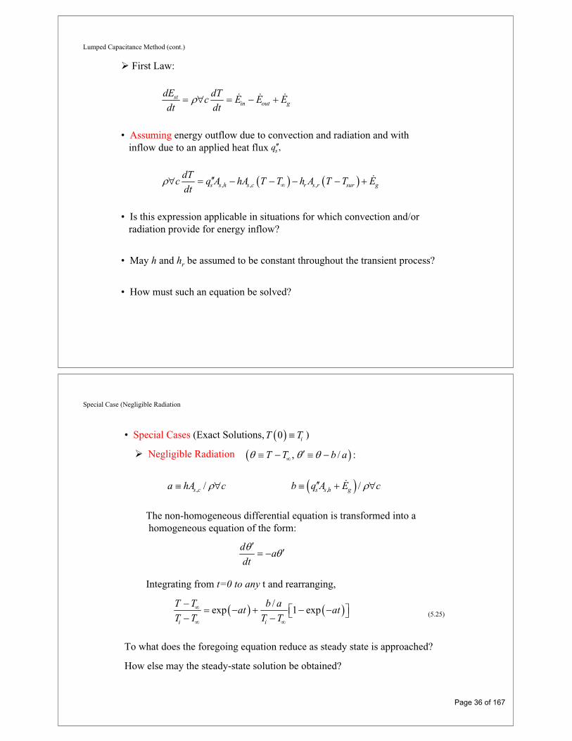
First Law:
stin out g
dE dTc E E E
dt dt
• Assuming energy outflow due to convection and radiation and withinflow due to an applied heat flux ,sq
, , ,s s h s c r s r sur g
dTc q A hA T T h A T T E
dt
• Is this expression applicable in situations for which convection and/orradiation provide for energy inflow?
• May h and hr be assumed to be constant throughout the transient process?
• How must such an equation be solved?
Special Case (Negligible Radiation
• Special Cases (Exact Solutions, ) 0 iT T
Negligible Radiation , / :T T b a
, ,/ /s c s s h ga hA c b q A E c
The non-homogeneous differential equation is transformed into a homogeneous equation of the form:
da
dt
Integrating from t=0 to any t and rearranging,
/exp 1 exp
i i
T T b aat at
T T T T (5.25)
To what does the foregoing equation reduce as steady state is approached?
How else may the steady-state solution be obtained?
Page 36 of 167

Special Case (Convection)
Negligible Radiation and Source Terms , 0, 0 :r g sh h E q
,s c
dTc hA T T
dt(5.2)
, is c
t
o
c d
hAdt
,s c
i i
hAT Texp t
T T cexp
t
t
The thermal time constant is defined as
,
1t
s c
chA (5.7)
ThermalResistance, Rt
Lumped ThermalCapacitance, Ct
The change in thermal energy storage due to the transient process ist
st outo
E Q E dt,
t
s co
hA dt 1 expit
tc (5.8)
Special Case (Radiation)
Negligible Convection and Source Terms , 0, 0 :r g sh h E q
Assuming radiation exchange with large surroundings,
4 4,s r sur
dTc A T T
dt
,
4 4i
s r T
surTo
tA
c
dTT T
dt
3,
1 1n4
sur sur i
s r sur sur sur i
T T T Tct n
A T T T T T
(5.18)
Result necessitates implicit evaluation of T(t).
1 12 tan tan i
sur sur
TT
T T
Page 37 of 167

Biot Number The Biot Number and Validity ofThe Lumped Capacitance Method
• The Biot Number: The first of many dimensionless parameters to beconsidered.
Definition:chL
Bik
thermal conductivity of t soe dh lik
of the solid ( / or coordinate
associated with maximum spati
characteri
al temp
stic
erature differenc
n
e)
le gthc sL A
Physical Interpretation:
/
/1/ h
c s cond solid
s conv solid fluid
L kA R TBi
A R T
Criterion for Applicability of Lumped Capacitance Method:
1Bi
h convection or radiation coefficient
Problem: Thermal Energy Storage
Problem 5.12: Charging a thermal energy storage system consistingof a packed bed of aluminum spheres.
KNOWN: Diameter, density, specific heat and thermal conductivity of aluminum spheres used in packed bed thermal energy storage system. Convection coefficient and inlet gas temperature.
FIND: Time required for sphere at inlet to acquire 90% of maximum possible thermal energy and the corresponding center temperature.
Schematic:
Page 38 of 167

Problem: Thermal Energy Storage (cont.)
ASSUMPTIONS: (1) Negligible heat transfer to or from a sphere by radiation or conduction due to contact with other spheres, (2) Constant properties.
Hence, the lumped capacitance approximation may be made, and a uniform temperature may be assumed to exist in the sphere at any time.
From Eq. 5.8a, achievement of 90% of the maximum possible thermal energy storage corresponds to
stt
i
E0.90 1 exp t /
cV
tt ln 0.1 427s 2.30 984s
From Eq. (5.6), the corresponding temperature at any location in the sphere is
g,i i g,iT 984s T T T exp 6ht / Dc2 3T 984s 300 C 275 C exp 6 75 W / m K 984s / 2700 kg / m 0.075m 950 J / kg K
If the product of the density and specific heat of copper is ( c)Cu 8900 kg/m3 400 J/kg K = 3.56 106 J/m3 K, is there any advantage to using copper spheres of equivalent diameter in lieu of aluminum spheres?
Does the time required for a sphere to reach a prescribed state of thermal energy storage change with increasing distance from the bed inlet? If so, how and why?
T 984s 272.5 C
3
t s 2
2700 kg / m 0.075m 950 J / kg KVc / hA Dc / 6h 427s.
6 75 W / m K
ANALYSIS: To determine whether a lumped capacitance analysis can be used, first computeBi = h(ro/3)/k = 75 W/m2·K (0.0125m)/150 W/m·K = 0.006 << 1.
Problem: Furnace Start-up
Problem 5.16: Heating of coated furnace wall during start-up.
KNOWN: Thickness and properties of furnace wall. Thermal resistance of ceramic coating on surface of wall exposed to furnace gases. Initial wall temperature.
FIND: (a) Time required for surface of wall to reach a prescribed temperature, (b) Corresponding value of coating surface temperature.
Schematic:
Page 39 of 167

Problem: Furnace Start-up
ASSUMPTIONS: (1) Constant properties, (2) Negligible coating thermal capacitance, (3) Negligible radiation.
PROPERTIES: Carbon steel: = 7850 kg/m3, c = 430 J/kg K, k = 60 W/m K.
ANALYSIS: Heat transfer to the wall is determined by the total resistance to heat transfer from the gas to the surface of the steel, and not simply by the convection resistance.
111 2 2 2
tot f 21 1
U R R 10 m K/W 20 W/m K.h 25 W/m K
2UL 20 W/m K 0.01 mBi 0.0033 1
k 60 W/m K
and the lumped capacitance method can be used.
(a) From Eqs. (5.6) and (5.7),
t t ti
T Texp t/ exp t/R C exp Ut/ Lc
T T
3
2i
7850 kg/m 0.01 m 430 J/kg KT TLc 1200 1300t ln ln
U T T 300 130020 W/m K
t 3886s 1.08h.
Hence, with
Problem: Furnace Start-up (cont.)
(b) Performing an energy balance at the outer surface (s,o),
s,o s,o s,i fh T T T T / R
2 -2 2s,i f
s,o 2f
hT T / R 25 W/m K 1300 K 1200 K/10 m K/WT
h 1/ R 25 100 W/m K
s,oT 1220 K.
How does the coating affect the thermal time constant?
Page 40 of 167

Transient Conduction:Spatial Effects and the Role of
Analytical Solutions
Chapter 5Sections 5.4 through 5.8
Plane Wall Solution to the Heat Equation for a Plane Wall withSymmetrical Convection Conditions
• If the lumped capacitance approximation can not be made, consideration mustbe given to spatial, as well as temporal, variations in temperature during thetransient process.
• For a plane wall with symmetrical convectionconditions and constant properties, the heatequation and initial/boundary conditions are:
2
2
1T T
x t (5.26)
,0 iT x T (5.27)
0
0x
T
x(5.28)
,x L
Tk h T L t T
x(5.29)
• Existence of seven independent variables:, , , , , ,iT T x t T T k h (5.30)
How may the functional dependence be simplified?
Page 41 of 167

Plane Wall (cont.)
• Non-dimensionalization of Heat Equation and Initial/Boundary Conditions:
Dimensionless temperature difference: *
i i
T T
T T* x
xL
Dimensionless coordinate:
Dimensionless time: *2
tt Fo
LFourier the NumberFo
The Biot Number:solid
hLBi
k* *, ,f x Fo Bi
• Exact Solution:
* 2 *
1exp cosn n n
nC Fo x (5.39a)
4sin tan2 sin 2
nn n n
n n
C Bi (5.39b,c)
See Appendix B.3 for first four roots (eigenvalues ) of Eq. (5.39c)1 4,...,
Plane Wall (cont.)
• The One-Term Approximation :Valid for 0.2Fo
Variation of midplane temperature (x*= 0) with time : Fo
* 21 1expo
oi
T TC Fo
T T(5.41)
1 1Table 5.1 and as a function of C Bi
Variation of temperature with location (x*) and time : Fo* * *
1coso x (5.40b)
Change in thermal energy storage with time:
stE Q (5.43a)
1 *
1
sin1o oQ Q (5.46)
o iQ cV T T (5.44)
Can the foregoing results be used for a plane wall that is well insulated on oneside and convectively heated or cooled on the other?
Can the foregoing results be used if an isothermal condition is instantaneously imposed on both surfaces of a plane wall or on one surface ofa wall whose other surface is well insulated?
s iT T
Page 42 of 167

Heisler Charts
Graphical Representation of the One-Term ApproximationThe Heisler Charts, Section 5 S.1
• Midplane Temperature:
Heisler Charts (cont.)
• Temperature Distribution:
• Change in Thermal Energy Storage:
Page 43 of 167

Radial Systems
Radial Systems• Long Rods or Spheres Heated or Cooled by Convection.
2
//
o
o
Bi hr k
Fo t r
• One-Term Approximations:Long Rod: Eqs. (5.49) and (5.51)
Sphere: Eqs. (5.50) and (5.52)
1 1, Table 5.1C
• Graphical Representations:Long Rod: Figs. 5 S.4 – 5 S.6
Sphere: Figs. 5 S.7 – 5 S.9
Page 44 of 167

University of Florida EML4140 §5964 Spring 2008
http://www.mae.ufl.edu/courses/spring2008/eml4140
EML4140 HEAT TRANSFER BLOCK II CONVECTION
Page 45 of 167

Introduction to Convection:Flow and Thermal Considerations
Chapter Six and Appendix DSections 6.1 through 6.8
and D.1 through D.3
Boundary Layer Features
Boundary Layers: Physical Features• Velocity Boundary Layer
– A consequence of viscous effectsassociated with relative motionbetween a fluid and a surface.
– A region of the flow characterized byshear stresses and velocity gradients.
– A region between the surfaceand the free stream whosethickness increases in the flow direction.
0.99u y
u
– Why does increase in the flow direction?
– Manifested by a surface shearstress that provides a drag force, .
s
DF
0s y
u
y
sD s s
A
F dA
– How does vary in the flowdirection? Why?
s
Page 46 of 167

Boundary Layer Features (cont.)
• Thermal Boundary Layer
– A consequence of heat transfer between the surface and fluid.
– A region of the flow characterizedby temperature gradients and heatfluxes.
– A region between the surface andthe free stream whose thicknessincreases in the flow direction.
t
– Why does increase in theflow direction?
t
– Manifested by a surface heatflux and a convection heattransfer coefficient h .
sq
0.99st
s
T T y
T T
0s f y
Tq k
y
0/f y
s
k T yh
T T
– If is constant, how do andh vary in the flow direction?
sT Tsq
Local and Average Coefficients
Distinction between Local andAverage Heat Transfer Coefficients
• Local Heat Flux and Coefficient:
s sq h T T
• Average Heat Flux and Coefficient for a Uniform Surface Temperature:
s sq hA T T
s sAq q dAss sAT T hdA
1s sA
s
h hdAA
• For a flat plate in parallel flow:1 L
oh hdxL
Page 47 of 167

Transition
Boundary Layer Transition
• How would you characterize conditions in the laminar region of boundary layerdevelopment? In the turbulent region?
• What conditions are associated with transition from laminar to turbulent flow?
• Why is the Reynolds number an appropriate parameter for quantifying transitionfrom laminar to turbulent flow?
• Transition criterion for a flat plate in parallel flow:
, critical Reynolds numRe bercx c
u x
location at which transition to turbulence beginscx5 6
,~ ~10 Re 3 x 10x c
Transition (cont.)
What may be said about transition if ReL < Rex,c? If ReL > Rex,c?
• Effect of transition on boundary layer thickness and local convection coefficient:
Why does transition provide a significant increase in the boundary layer thickness?
Why does the convection coefficient decay in the laminar region? Why does it increase significantly with transition to turbulence, despite the increase in the boundary layerthickness? Why does the convection coefficient decay in the turbulent region?
Page 48 of 167

Boundary Layer Equations
The Boundary Layer Equations
• Consider concurrent velocity and thermal boundary layer development for steady,two-dimensional, incompressible flow with constant fluid properties andnegligible body forces.
,, pc k
• Apply conservation of mass, Newton’s 2nd Law of Motion and conservation of energyto a differential control volume and invoke the boundary layer approximations.
Velocity Boundary Layer:
2 2
2 2 ,u u p dp
x dxx y
Thermal Boundary Layer:2 2
2 2T T
x y
Boundary Layer Equations (cont.)
• Conservation of Mass:
0u v
x yIn the context of flow through a differential control volume, what is the physicalsignificance of the foregoing terms, if each is multiplied by the mass density of the fluid?
• Newton’s Second Law of Motion:
2
2
x-directi :on
1u u dp uu v
x y dx y
What is the physical significance of each term in the foregoing equation?
Why can we express the pressure gradient as dp /dx instead of / ?p x
Page 49 of 167

Boundary Layer Equations (cont.)
What is the physical significance of each term in the foregoing equation?
What is the second term on the right-hand side called and under what conditionsmay it be neglected?
• Conservation of Energy:22
2p
T T T uu v
x y y c y
Similarity Considerations Boundary Layer Similarity• As applied to the boundary layers, the principle of similarity is based on
determining similarity parameters that facilitate application of results obtainedfor a surface experiencing one set of conditions to geometrically similar surfacesexperiencing different conditions. (Recall how introduction of the similarityparameters Bi and Fo permitted generalization of results for transient, one-dimensional condition).
• Dependent boundary layer variables of interest are:
and or s q h
• For a prescribed geometry, the corresponding independent variables are:
Geometrical: Size (L), Location (x,y)Hydrodynamic: Velocity (V)Fluid Properties:
Hydrodynamic: ,Thermal : ,pc k
Hence,, , , , ,
, , , ,s
u f x y L V
f x L V
Page 50 of 167

Similarity Considerations (cont.)
and
, , , , , , ,
, , , , , ,
p
p
T f x y L V c k
h f x L V c k
• Key similarity parameters may be inferred by non-dimensionalizing the momentumand energy equations.
• Recast the boundary layer equations by introducing dimensionless forms of theindependent and dependent variables.
* *
* *
* s
s
x yx y
L Lu v
u vV V
T TT
T T
• Neglecting viscous dissipation, the following normalized forms of the x-momentum and energy equations are obtained:
* * * 2 ** *
* * * *2
* * 2 ** *
* * *2
1Re
1Re Pr
L
L
u u dp uu v
x y dx y
T T Tu v
x y y
Similarity Considerations (cont.)
Reynolds NumbeRe the
Pr the
r
Prandtl Num erb
L
p
VL VL
v
c v
k
• For a prescribed geometry,* * *, ,ReLu f x y
*
*
*0 0
s
y y
u V u
y L y
The dimensionless shear stress, or local friction coefficient, is then
*
*
2 *0
2/ 2 Re
sf
L y
uC
V y
*
**
*0
,ReL
y
uf x
y
*2 ,ReRef L
L
C f x
What is the functional dependence of the average friction coefficient?
How may the Reynolds and Prandtl numbers be interpreted physically?
Page 51 of 167

Similarity Considerations (cont.)
• For a prescribed geometry,* * *, ,Re ,PrLT f x y
**
* *0
* *00
/f y f fs
s s yy
k T y k kT T T Th
T T L T T y L y
The dimensionless local convection coefficient is then
*
**
*0
,Re ,PrLf y
hL TNu f x
k y
local Nusselt numberNu
What is the functional dependence of the average Nusselt number?
How does the Nusselt number differ from the Biot number?
Reynolds Analogy
The Reynolds Analogy• Equivalence of dimensionless momentum and energy equations for
negligible pressure gradient (dp*/dx*~0) and Pr~1:
Advection terms Diffusion
* * 2 ** *
* * *21
ReT T T
u vx y y
* * 2 ** *
* * *21
Reu u u
u vx y y
• Hence, for equivalent boundary conditions, the solutions are of the same form:
* *
* *
* *
* *0 0
Re2
y y
f
u T
u T
y y
C Nu
Page 52 of 167

Reynolds Analogy (cont.)
With Pr = 1, the Reynolds analogy, which relates important parameters of the velocityand thermal boundary layers, is
2fC
St
or, with the defined asStanton number ,
p
h NuSt
Vc Re Pr
• Modified Reynolds (Chilton-Colburn) Analogy
– An empirical result that extends applicability of the Reynolds analogy:
23Pr 0.6 Pr 60
2f
H
CSt j
Colburn j factor for heat transfer
– Applicable to laminar flow if dp*/dx* ~ 0.
– Generally applicable to turbulent flow without restriction on dp*/dx*.
Problem: Turbine Blade Scaling
Problem 6.19: Determination of heat transfer rate for prescribed turbine blade operating conditions from wind tunnel data obtained for a geometrically similar but smaller blade. The blade surface area may be assumed to be directly proportional to its characteristic length . sA L
SCHEMATIC:
ASSUMPTIONS: (1) Steady-state conditions, (2) Constant properties, (3) Surface area A is directly proportional to characteristic length L, (4) Negligible radiation, (5) Blade shapes are geometrically similar.
ANALYSIS: For a prescribed geometry,
LhLNu f Re ,Pr .k
Page 53 of 167

Problem: Turbine Blade Scaling (cont.)
Hence, with constant properties 1 2v v , L,1 L,2Re Re . Also, Pr Pr .1 2
Therefore,
2 1Nu Nu
2 2 2 1 1 1h L / k h L / k
1 1 12 1
2 2 1 s,1
L L qh h
L L A T T
The heat rate for the second blade is then
s,21 22 2 2 s,2 1
2 1 s,1
T TL Aq h A T T q
L A T T
s,22 1
s,1
T T 400 35q q 1500 W
T T 300 35
2q 2066 W.
COMMENTS: (i) The variation in from Case 1 to Case 2 would cause ReL,2 to differ from ReL,1. However, for air and the prescribed temperatures, this non-constant property effect is small. (ii) If the Reynolds numbers were not equal ,1 2Re Re ,L L knowledge of the specific form of
,Re PrLf would be needed to determine h2.
The Reynolds numbers for the blades are 2 2
L,1 1 1 1 1 L,2 2 2 2 2Re V L / 15m / s Re V L / 15m / s .
Problem: Nusselt Number
Problem 6.26: Use of a local Nusselt number correlation to estimate thesurface temperature of a chip on a circuit board.
KNOWN: Expression for the local heat transfer coefficient of air at prescribed velocity and temperature flowing over electronic elements on a circuit board and heat dissipation rate for a 4 4 mm chip located 120mm from the leading edge.
FIND: Surface temperature of the chip surface, Ts.
SCHEMATIC:
Page 54 of 167

Problem: Nusselt Number (cont.)
PROPERTIES: Table A-4, Air (Evaluate properties at the average temperature of air in the boundary layer. Assuming Ts = 45 C, Tave = (45 + 25)/2 = 35 C = 308K. Also, p = 1atm): = 16.69
10-6m2/s, k = 26.9 10-3 W/m K, Pr = 0.703.
ANALYSIS: From an energy balance on the chip,
conv gq E 30mW.
Newton’s law of cooling for the upper chip surface can be written as
s conv chipT T q / h A (2)
where 2chipA .
Assuming that the average heat transfer coefficient h over the chip surface is equivalent to the local
coefficient evaluated at x = L, that is, chip xh h L , the local coefficient can be evaluated by
applying the prescribed correlation at x = L.0.85
1/ 3xx
h x VxNu 0.04 Prk
0.851/ 3
Lk VLh 0.04 PrL
ASSUMPTIONS: (1) Steady-state conditions, (2) Power dissipated within chip is lost by convection across the upper surface only, (3) Chip surface is isothermal, (4) The average heat transfer coefficient for the chip surface is equivalent to the local value at x = L, (5) Negligible radiation.
Problem: Nusselt Number (cont.)
From Eq. (2), the surface temperature of the chip is 2-3 2
sT 25 C 30 10 W/107 W/m K 0.004m 42.5 C.
COMMENTS: (1) The estimated value of Tave used to evaluate the air properties is reasonable.
(2) How else could chiph have been evaluated? Is the assumption of Lh h reasonable?
0.851/ 3 2
L -6 20.0269 W/m K 10 m/s 0.120 mh 0.04 0.703 107 W/m K.
0.120 m 16.69 10 m / s
Page 55 of 167

External Flow:The Flat Plate in Parallel Flow
Chapter 7
Section 7.1 through 7.3
Physical Features
Physical Features
• As with all external flows, the boundary layers develop freely without constraint.
• Boundary layer conditions may be entirely laminar, laminar and turbulent,or entirely turbulent.
• To determine the conditions, compute
and compare with the critical Reynolds number for transition to turbulence,
ReL
u L u L
,Re .x c
, laminar flow tRe Re hroughoutL x c
, ,transition to turbulent flowRe Re at / Re / ReL x c c x c Lx L
Page 56 of 167

Physical Features (cont.)
,Rex c• Value of depends on free stream turbulence and surface roughness. Nominally,
5
, 5 10Re .x c
• If boundary layer is tripped at the leading edge
and the flow is turbulent throughout.
,Re 0x c
• Surface thermal conditions are commonly idealized as being of uniformtemperature or uniform heat flux .sT sq Is it possible for a surface to beconcurrently characterized by uniform temperature and uniform heat flux?
• Thermal boundary layer development may be delayed by an unheatedstarting length.
Equivalent surface and free stream temperatures for and uniform(or ) for .
x sT
sq x
Similarity Solution
Similarity Solution for Laminar, Constant-Property Flow over an Isothermal Plate
• Based on premise that the dimensionless x-velocity component, ,and temperature, , can be represented exclusively interms of a dimensionless similarity parameter
/u u* /s sT T T T T
1/ 2/y u x
• Similarity permits transformation of the partial differential equations associatedwith the transfer of x-momentum and thermal energy to ordinary differentialequations of the form
3 2
3 22 0d f d f
fd d
where / / , u u df d
2 * *
2
Pr0
2
d T dTf
d d
and
Page 57 of 167

Similarity Solution (cont.)
• Subject to prescribed boundary conditions, numerical solutions to the momentumand energy equations yield the following results for important local boundary layerparameters:
1/ 2 1/ 2
- with / 0.99 at 5.
5.0 5
/
0,
Rex
x
u vx
u u
2
20 0
- with /s
y
u d fu u vx
y d
2 2
0and / 0.332,d f d
, 1/ 2, 2 0.664Re
/ 2 x
s xf xC
u1/ 2* *
0 0- with / / / /x s s y
h q T T k T y k u vx dT d
* 1/ 3
0and / 0.332 Pr for Pr 0.6,dT d
1/ 2 1/ 30.332 Re Prxx x
h xNu
k
1/ 3r
and
Pt
Similarity Solution (cont.)
• How would you characterize relative laminar velocity and thermal boundary layergrowth for a gas? An oil? A liquid metal?
• How do the local shear stress and convection coefficient vary with distance fromthe leading edge?
• Average Boundary Layer Parameters:
, 0
1 xs x sdx
x1/ 2
, 1.328 Rexf x
C
0
1 xx xh
xh dx
1/ 2 1/ 30.664 Re Prx xNu
• The effect of variable properties may be considered by evaluating all propertiesat the film temperature.
2s
f
T TT
Page 58 of 167

Turbulent Flow
Turbulent Flow• Local Parameters:
1/ 5,
4 / 5 1/ 3
0.0592 Re
0.0296 Re Pr
f x x
x x
C
NuEmpirical
Correlations
How do variations of the local shear stress and convection coefficient withdistance from the leading edge for turbulent flow differ from those for laminar flow?
• Average Parameters:
0
1 c
c
x LL 1am turbxh h dx h dx
L
Substituting expressions for the local coefficients and assuming 5
x,cRe 5 10 ,
, 1/ 5
0.074 1742
Re Ref LL L
C
4 / 5 1/ 30.037 Re 871 PrL LNu
, ,
1/5,
4 /5 1/ 3
For Re 0 or Re Re ,
0.074 Re
0.037 Re Pr
x c c L x c
f L L
L L
L x
C
Nu
Special Cases
Special Cases: Unheated Starting Length (USL)and/or Uniform Heat Flux
For both uniform surface temperature (UST) and uniform surface heat flux (USF),the effect of the USL on the local Nusselt number may be represented as follows:
0
1/ 30
1 /
Re Pr
x
x ba
mx x
NuNu
x
Nu C4/54/51/21/2m
0.03080.02960.4530.332C
1/91/91/31/3b
9/109/103/43/4a
USFUSTUSFUST
TurbulentLaminar
Sketch the variation of hx versus for two conditions:What effect does an USL have on the local convection coefficient?
x 0 and 0.
Page 59 of 167

Special Cases (cont.)
• UST:
s x sq h T T
/ 11 / 2
0
laminar
1 /
2 for throughof ut
= 8 for t
low
turbulent hrougfl ho ow ut
p pp p
L LL
Nu Nu LL
p
p
1
laminar/turbulent flow numerical integration for
1 c
c
L
x LL am turbx
h
h h dx h dxL
• USF:s
sx
qT T
h s sq q A
• Treatment of Non-Constant Property Effects:
Evaluate properties at the film temperature.
2s
f
T TT
L s sq h A T T
Problem: Orientation of Heated Surface
Problem 7.21: Preferred orientation (corresponding to lower heat loss) and the corresponding heat rate for a surface with adjoining smooth and roughened sections.
SCHEMATIC:
ASSUMPTIONS: (1) Surface B is sufficiently rough to trip the boundary layer when in the upstream position
(Configuration 2); (2) 5x,cRe 5 10 for flow over A in Configuration 1.
Page 60 of 167

Orientation of Heated Surface (cont.)
PROPERTIES: Table A-4, Air (Tf = 333K, 1 atm): = 19.2 10-6
m2/s, k = 28.7 10
-3
W/m K, Pr = 0.7.
ANALYSIS: With
6L -6 2
u L 20 m/s 1mRe 1.04 10 .
19.2 10 m / s
transition will occur just before the rough surface (xc = 0.48m) for Configuration 1. Hence,
L,1
4 / 56 1/3Nu 0.037 1.04 10 871 0.7 1366
For Configuration 1: L,1L,1h L
Nu 1366.k
Hence 3 2
L,1h 1366 28.7 10 W/m K /1m 39.2 W/m K
21 L,1 sq h A T T 39.2 W/m K 0.5m 1m 100 20 K 1568 W <
Comment: For a very short plate, a lower heat loss may be associated with Configuration 2. In fact, parametric calculations reveal that for L< 30 mm, this configuration provides the preferred orientation.
L,2 L,1
4 / 5 1/ 36Since Nu 0.037 1.04 10 0.7 2139 Nu , it follows that the lowest heat
transfer is associated with Configuration 1.
Problem: Conveyor Belt
Problem 7.24: Convection cooling of steel plates on a conveyor byair in parallel flow.
KNOWN: Plate dimensions and initial temperature. Velocity and temperature of air in parallel flow over plates.
FIND: Initial rate of heat transfer from plate. Rate of change of plate temperature.
Page 61 of 167

Problem: Conveyor Belt (cont.)
PROPERTIES: Table A-1, AISI 1010 steel (573K): kp = 49.2 W/m K, c = 549 J/kg K, = 7832
kg/m3. Table A-4, Air (p = 1 atm, Tf = 433K): = 30.4 10
-6 m
2/s, k = 0.0361 W/m K, Pr = 0.688.
ANALYSIS: The initial rate of heat transfer from a plate is2
s i iq 2 h A T T 2 h L T T
With 6 2 5LRe u L / 10 m / s 1m / 30.4 10 m / s 3.29 10 , flow is laminar over the entire surface.
Hence,
L
1/ 2 1/ 31/ 2 1/ 3 5LNu 0.664 Re Pr 0.664 3.29 10 0.688 336
L2h k / L Nu 0.0361W / m K /1m 336 12.1W / m K
22q 2 12.1W / m K 1m 300 20 C 6780 W
SCHEMATIC:
ASSUMPTIONS: (1) Negligible radiation, (2) Negligible effect of conveyor velocity on boundary layer development, (3) Plates are isothermal, (4) Negligible heat transfer from edges of plate, (5)
5x,cRe 5 10 , (6) Constant properties.
Problem: Conveyor Belt (cont.)
COMMENTS: (1) With 4pBi h / 2 / k 7.4 10 , use of the lumped capacitance method is
appropriate.
(2) Despite the large plate temperature and the small convection coefficient, if adjoining plates are in close proximity, radiation exchange with the surroundings will be small and the assumption of negligible radiation is justifiable.
Performing an energy balance at an instant of time for a control surface about the plate, out stE E ,
2 2i
i
dTL c h 2L T T
dt2
3i
2 12.1W / m K 300 20 CdT0.26 C / s
dt 7832 kg / m 0.006m 549J / kg K
Page 62 of 167

Cylinder in Cross Flow
The Cylinder in Cross Flow• Conditions depend on special features of boundary layer development, including
onset at a stagnation point and separation, as well as transition to turbulence.
– Stagnation point: Location of zero velocity and maximum pressure.0u
– Followed by boundary layer development under a favorable pressure gradientand hence acceleration of the free stream flow ./ 0dp dx / 0du dx
– As the rear of the cylinder is approached, the pressure must begin to increase.Hence, there is a minimum in the pressure distribution, p(x), after which boundarylayer development occurs under the influence of an adverse pressure gradient
/ 0, / 0 .dp dx du dx
Cylinder in Cross Flow (cont.)
– Separation occurs when the velocity gradient reduces to zero0/ ydu dy
and is accompanied by flow reversal and a downstream wake.
– Location of separation depends on boundary layer transition.
ReD
VD VD
Page 63 of 167

Cylinder in Cross Flow (cont.)
– What features differentiate boundary development for the flat plate inparallel flow from that for flow over a cylinder?
• Force imposed by the flow is due to the combination of friction and form drag.
The dimensionless form of the drag force is
2Figure 7.8
/ 2D
D
f
FC
A V
Cylinder in Cross Flow (cont.)
• Heat Transfer Considerations
– The Local Nusselt Number:
– How does the local Nusselt number vary with for ? 5Re 2 10D
What conditions are associated with maxima and minima in the variation?
– How does the local Nusselt number vary with 5Re 2 10 ?D for What conditions are associated with maxima and minima in the variation?
– The Average Nusselt Number / :DNu hD k
– Churchill and Bernstein Correlation:4 / 55 / 81/ 2 1/ 3
1/ 42 / 3
0.62Re Pr Re0.3 1282,0001 0.4 / Pr
D DDNu
– Cylinders of Noncircular Cross Section:1/ 3Re Prm
D DNu C
, Table 7.3C m
Page 64 of 167

Problem: Extrusion Process
Problem 7.63: Cooling of extruded copper wire by convection and radiation.
KNOWN: Velocity, diameter, initial temperature and properties of extruded wire. Temperature and velocity of air. Temperature of surroundings.
FIND: (a) Differential equation for temperature distribution T(x) along the wire, (b) Exact solution for negligible radiation and corresponding value of temperature at prescribed length ( x = L = 5m) of wire, (c) Effect of radiation on temperature of wire at prescribed length. Effect of wire velocity and emissivity on temperature distribution.
Problem: Extrusion Process (cont.)
SCHEMATIC:
ASSUMPTIONS: (1) Negligible variation of wire temperature in radial direction, (2) Negligible effect of axial conduction along the wire, (3) Constant properties, (4) Radiation exchange between small surface and large enclosure, (5) Motion of wire has a negligible effect on the convection coefficient (Ve << V).
PROPERTIES: Copper: 3p8900 kg / m , c 400 J / kg K, 0.55. Air: k 0.037 W / m K,
5 23 10 m / s, Pr 0.69.
ANALYSIS: (a) Applying conservation of energy to a stationary control surface, through which the wire moves, steady-state conditions exist and in outE E 0.
Hence, with inflow due to advection and outflow due to advection, convection and radiation,e c p e c p conv radV A c T V A c T dT dq dq 0
Page 65 of 167

Problem: Extrusion Process (cont.)
2 4 4e p surV D / 4 c dT Ddx h T T T T 0
4 4sur
e p
dT 4 h T T T Tdx V D c
(1) <
Alternatively, if the control surface is fixed to the wire, conditions are transient and the energy balance is of the form, out stE E , or
24 4
sur pD dTDdx h T T T T dx c4 dt
4 4sur
p
dT 4 h T T T Tdt Dc
Dividing the left- and right-hand sides of the equation by dx/dt and eV dx / dt, respectively, Eq. (1) is obtained.
(b) Neglecting radiation, separating variables and integrating, Eq. (1) becomes
i
T xT 0e p
dT 4h dxT T V Dc
i e p
T T 4h xlnT T V Dc
ie p
4hxT T T T expV Dc
(2) <
Problem: Extrusion Process (cont.)
With 5 2DRe VD / 5 m / s 0.005 m / 3 10 m / s 833, the Churchill-Bernstein correlation yields
D
4 / 51/ 2 1/ 3 5/8
1/ 42 / 3
0.62 833 0.69 833Nu 0.3 1 14.4282,000
1 0.4 / 0.69
D2k 0.037 W / m Kh Nu 14.4 107 W / m K
D 0.005m
Hence, applying Eq. (2) at x = L,2
o 34 107 W / m K 5mT 25 C 575 C exp
8900kg / m 0.2m / s 0.005m 400 J / kg K
oT 340 C <
Hence, radiation makes a discernable contribution to cooling of the wire.
(c) Numerically integrating from x = 0 to x = L = 5.0m, we obtain
oT 309 C <
Page 66 of 167

Problem: Extrusion Process (cont.)
Parametric calculations reveal the following distributions.
0 1 2 3 4 5
Distance from extruder exit, x(m)
100
200
300
400
500
600
Wire
tem
pera
ture
, T(C
)
Ve=0.5 m/sVe=0.2 m/sVe=0.1 m/s
0 1 2 3 4 5
Distance from extruder exit, x(m)
300
350
400
450
500
550
600
Wire
tem
pera
ture
, T(C
)
eps=0.8eps=0.55eps=0
The speed with which the wire is drawn from the extruder has a significant influence on the temperature distribution. The temperature decay decreases with increasing Ve due to the increasing effect of advection on energy transfer in the x direction.
The effect of the surface emissivity is less pronounced, although, as expected, the temperature decay becomes more pronounced with increasing .
COMMENTS: (1) A critical parameter in wire extrusion processes is the coiling temperature, that is, the temperature at which the wire may be safely coiled for subsequent storage or shipment. The larger the production rate (Ve), the longer the cooling distance needed to achieve a desired coiling temperature.
(2) Cooling may be enhanced by increasing the cross-flow velocity, and the specific effect of V may also be explored.
Internal Flow:General Considerations
Chapter 8
Sections 8.1 through 8.3
Page 67 of 167

Entrance Conditions
Entrance Conditions• Must distinguish between entrance and fully developed regions.
• Hydrodynamic Effects: Assume laminar flow with uniform velocity profile atinlet of a circular tube.
– Velocity boundary layer develops on surface of tube and thickens with increasing x.
– Inviscid region of uniform velocity shrinks as boundary layer grows.
Does the centerline velocity change with increasing x? If so, how does it change?
– Subsequent to boundary layer merger at the centerline, the velocity profilebecomes parabolic and invariant with x. The flow is then said to be hydrodynamically fully developed.
How would the fully developed velocity profile differ for turbulent flow?
Entrance Conditions (cont)
• Thermal Effects: Assume laminar flow with uniform temperature, , atinlet of circular tube with uniform surface temperature, , or heat flux, .
,0 iT r T
s iT T sq
– Thermal boundary layer develops on surface of tube and thickens with increasing x.
– Isothermal core shrinks as boundary layer grows.
– Subsequent to boundary layer merger, dimensionless forms of the temperatureprofile become independent of x.for and s sT q Conditions are then said to bethermally fully developed.
Is the temperature profile invariant with x in the fully developed region?
Page 68 of 167

Entrance Conditions (cont)
For uniform surface temperature, what may be said about the changein the temperature profile with increasing x?
For uniform surface heat flux, what may be said about the change in thetemperature profile with increasing x?
How do temperature profiles differ for laminar and turbulent flow?
Mean Quantities
The Mean Velocity and Temperature• Absence of well-defined free stream conditions, as in external flow, and hence a
reference velocity or temperature , dictates the use of a cross-sectional mean velocity and temperature for internal flow.
u T
mu mT
or,
,cA cm u r x d A
Hence,
,cA c
mc
u r x d Au
A
orFor incompressible flow in a circular tube of radius ,
2
2,
or
m o
o
u u r x r drr
• Linkage of mean velocity to mass flow rate:
m cm u A
Page 69 of 167

Mean Quantities (cont)
• Linkage of mean temperature to thermal energy transport associated with flow through a cross section:
ct A p c p mE uc T dA mc T
Hence,
cA p cm
p
uc T dAT
mc
• For incompressible, constant-property flow in a circular tube,
02
2, ,
or
mm o
T u x r T x r r dru r
• Newton’s Law of Cooling for the Local Heat Flux:
s s mq h T T
What is the essential difference between use of for internal flow andfor external flow?
mT T
Entry Lengths
Hydrodynamic and Thermal Entry Lengths
• Entry lengths depend on whether the flow is laminar or turbulent, which, in turn,depend on Reynolds number.
Re m hD
u D
The hydraulic diameter is defined as
4 ch
AD
Pin which case,
4Re m h
D
u D m
P
For a circular tube,
4Re m
D
u D m
D
Page 70 of 167

Entry Lengths (cont)
– Onset of turbulence occurs at a critical Reynolds number of
,Re 2300D c
– Fully turbulent conditions exist for
Re 10,000D
• Hydrodynamic Entry Length
,Laminar Flow: / 0.05Refd h Dx D
,Turbulent Flow: 10 / 60fd hx D
• Thermal Entry Length
,Laminar Flow: / 0.05 Re Prfd t Dx D
,Turbulent Flow: 10 / 60fd tx D
• For laminar flow, how do hydrodynamic and thermal entry lengths compare for a gas?An oil? A liquid metal?
Fully Developed Flow
Fully Developed Conditions
• Assuming steady flow and constant properties, hydrodynamic conditions, includingthe velocity profile, are invariant in the fully developed region.
What may be said about the variation of the mean velocity with distance from thetube entrance for steady, constant property flow?
• The pressure drop may be determined from knowledge of the friction factorf, where,
2
/
/ 2m
dp dx Df
u
Laminar flow in a circular tube:
64
ReD
f
Turbulent flow in a smooth circular tube:2
0.790 1n Re 1.64Df
Page 71 of 167

Fully Developed Flow (cont)
Turbulent flow in a roughened circular tube:
Pressure drop for fully developed flow from x1 to x2:2
1 2 2 12mu
p p p f x xD
and power requirementpm
P p
Fully Developed Flow (cont)
• Requirement for fully developed thermal conditions:
,
,0s
s m fd t
T x T r x
x T x T x
• Effect on the local convection coefficient:/
o
o
r rs
s m s mr r
T rT Tf x
r T T T T
Hence, assuming constant properties,
/s
s m
q k hf x
T T k
h f x
Variation of h in entrance and fully developed regions:
Page 72 of 167

Mean Temperature
Determination of the Mean Temperature
• Determination of is an essential feature of an internal flow analysis.mT x
Determination begins with an energy balance for a differential control volume.
conv p m m m p mdq mc T dT T mc dT
Integrating from the tube inlet to outlet,
, , (1)conv p m o m iq mc T T
Mean Temperature (cont)
A differential equation from which may be determined is obtained bysubstituting for
mT x.
conv s s mdq q P dx h T T P dx
2m ss m
p p
dT q P Ph T T
dx mc mc
• Special Case: Uniform Surface Heat Flux
m s
p
dT q Pf x
dx mc
,s
m m ip
q PT x T x
mc
Why does the surface temperature vary with x as shown in the figure?
In principle, what value does Ts assume at x=0?
Total heat rate:
conv sq q PL
T
Page 73 of 167

Mean Temperature (cont)
• Special Case: Uniform Surface Temperature
From Eq. (2), with s m
m
p
T T T
d Td T Ph T
dx dx mc
Integrating from x=0 to any downstream location,
,
exps mx
s m i p
T T x Pxh
T T mc
01
x x
xh h dx
x
Overall Conditions:
,
,
exp exps m oo s
i s m i p p
T TT h APLh
T T T mc mc
conv s mq h A T
31n /
o im
o i
T TT
T T
Mean Temperature (cont)
• Special Case: Uniform External Fluid Temperature
,
,
1exp expm oo s
i m i p p tot
T TT U A
T T T mc mc R
ms m
tot
Tq UA T
R
Eq. (3) with replaced by .m sT T T
Note: Replacement of by Ts,o if outer surface temperature is uniform.T
Page 74 of 167

Problem: Water Flow Through Pipe in Furnace
Problem 8.17: Estimate temperature of water emerging from a thin-walledtube heated by walls and air of a furnace. Inner and outerconvection coefficients are known.
KNOWN: Water at prescribed temperature and flow rate enters a 0.25 m diameter, black thin-walled tube of 8-m length, which passes through a large furnace whose walls and air are at a temperature of Tfur = T = 700 K. The convection coefficients for the internal water flow and external furnace air are 300 W/m2 K and 50 W/m2 K, respectively.
FIND: The outlet temperature of the water, Tm,o.
Problem: Water Flow Through Pipe in Furnace (cont)
SCHEMATIC:
ASSUMPTIONS: (1) Steady-state conditions; (2) Tube is small object with large, isothermal surroundings; (3) Furnace air and walls are at the same temperature; (4) Tube is thin-walled with black surface; and (5) Incompressible liquid with negligible viscous dissipation.
PROPERTIES: Table A-6, Water: cp 4180 J/kg K.
ANALYSIS: The linearized radiation coefficient may be estimated from Eq. 1.9 with = 1,
2 2rad t fur t furh T T T T
where tT represents the average tube wall surface temperature, which can be estimated from an energy balance
on the tube.
As represented by the thermal circuit, the energy balance may be expressed as
m t t fur1cv,i cv,o rad
T T T TR 1/ R 1/ R
The thermal resistances, with As = PL = DL, are
cv,i i s cv,o o s rad radR 1/ h A R 1/ h A R 1/ h As
Page 75 of 167

Problem: Water Flow Through Pipe in Furnace (cont)
and the mean temperature of the water is approximated as
m m,i m,oT T T / 2
The outlet temperature can be calculated from Eq. 8.45b, with Tfur = T ,
T T 1expT T m c R
m,o
m,i p tot
where
tot cv,icv,o rad
1R R
1/ R 1/ RWith
Rcv,i = 5.305 × 10⁻⁴ K/W Rcv,o = 3.183 × 10⁻³ K/W Rrad = 2.296 × 10⁻³ K/W
It follows that
Tm = 304.1 K Tt = 395.6 K Tm,o = 308.3 K <_
Fully Developed Flow Fully Developed Flow• Laminar Flow in a Circular Tube:
The local Nusselt number is a constant throughout the fully developedregion, but its value depends on the surface thermal condition.
– Uniform Surface Heat Flux :( )sq
4.36DhDNuk
– Uniform Surface Temperature :( )sT
3.66DhDNuk
• Turbulent Flow in a Circular Tube:– For a smooth surface and fully turbulent conditions , the
Dittus – Boelter equation may be used as a first approximation: Re 10,000D
4 / 50.023Re PrnD DNu
1/ 2 2 / 3
/8 Re 1000 Pr
1 12.7 /8 Pr 1D
D
fNu
f
– The effects of wall roughness and transitional flow conditionsmay be considered by using the Gnielinski correlation:
Re 3000D
0.30.4
s m
s m
n T Tn T T
Page 76 of 167

Fully Developed (cont.)
Smooth surface:2
0.790 1n Re 1.64Df
Surface of roughness : 0e
Figure 8.3f
• Noncircular Tubes:– Use of hydraulic diameter as characteristic length:
4 ch
AD
P– Since the local convection coefficient varies around the periphery of a tube,
approaching zero at its corners, correlations for the fully developed regionare associated with convection coefficients averaged over the peripheryof the tube.
– Laminar Flow:
The local Nusselt number is a constant whose value (Table 8.1) depends onthe surface thermal condition and the duct aspect ratio.ors sT q
– Turbulent Flow:
As a first approximation, the Dittus-Boelter or Gnielinski correlation may be used with the hydraulic diameter, irrespective of the surface thermal condition.
Entry Region
Effect of the Entry Region• The manner in which the Nusselt decays from inlet to fully developed conditions
for laminar flow depends on the nature of thermal and velocity boundary layerdevelopment in the entry region, as well as the surface thermal condition.
Laminar flow in acircular tube.
– Combined Entry Length:
Thermal and velocity boundary layers develop concurrently from uniformprofiles at the inlet.
Page 77 of 167

Entry Region (cont)
– Thermal Entry Length:
Velocity profile is fully developed at the inlet, and boundary layer development in the entry region is restricted to thermal effects. Such a condition may alsobe assumed to be a good approximation for a uniform inlet velocity profile if Pr 1. Why?
• Average Nusselt Number for Laminar Flow in a Circular Tube with UniformSurface Temperature:– Combined Entry Length:
1/ 3 0.14Re Pr/ / / 2 :D sL D
0.141/ 3Re Pr
1.86/D
D
s
NuL D
1/ 3 0.14Re Pr/ / / 2 :D sL D
3.66DNu
– Thermal Entry Length:
2 / 3
0.0668 / Re Pr3.66
1 0.04 / Re PrD
D
D
D LNu
D L
Entry Region (cont)
• Average Nusselt Number for Turbulent Flow in a Circular Tube :
– Effects of entry and surface thermal conditions are less pronounced forturbulent flow and can often be neglected.
– For long tubes :/ 60L D
,D D fdNu Nu
– For short tubes :/ 60L D
,
1/
Dm
D fd
Nu CNu L D
12 /3
Cm
• Noncircular Tubes:
– Laminar Flow:
depends strongly on aspect ratio, as well as entry region and surfacethermal conditions. See references 11 and 12.
hDNu
Page 78 of 167

Entry Region (cont)
• When determining for any tube geometry or flow condition, all properties are to be evaluated at
DNu
, , / 2m m i m oT T T
Why do solutions to internal flow problems often require iteration?
– Turbulent Flow:
As a first approximation, correlations for a circular tube may be usedwith D replaced by .hD
Annulus The Concentric Tube Annulus
• Fluid flow throughregion formed by concentric tubes.
• Convection heat transfermay be from or to innersurface of outer tube andouter surface of inner tube.
• Surface thermal conditions may be characterized byuniform temperature or uniform heat flux ., ,,s i s oT T ,i oq q
• Convection coefficients are associated with each surface, where
,i i s i mq h T T
,o o s o mq h T T
Page 79 of 167

Annulus (cont)
i h o hi o
h D h DNu Nu
k k
• Fully Developed Laminar Flow
Nusselt numbers depend on and surface thermal conditions (Tables 8.2, 8.3)/i oD D
• Fully Developed Turbulent Flow
Correlations for a circular tube may be used with replaced by .D hD
h o iD D D
Problem: Gas Turbine Vane
Problem 8.43: For an air passage used to cool a gas turbinevane, calculate the air outlet temperature andheat removed from the vane.
ASSUMPTIONS: (1) Steady-state conditions, (2) Ideal gas with negligible viscous dissipation and pressure variation.
PROPERTIES: Table A.4, Air (assume mT = 780 K, 1 atm): cp = 1094 J/kg K, k = 0.0563
W/m K, = 363.7 10-7 N s/m2, Pr = 0.706; (Ts = 650 C = 923 K, 1 atm): = 404.2 10-7
N s/m2.
FIND: (a) Outlet temperature of the air coolant for the prescribed conditions and (b) Compute and plot the air outlet temperature Tm,o as a function of flow rate, 0.1 m 0.6 kg/h. Compare this result with those for vanes having passage diameters of 2 and 4 mm.
KNOWN: Gas turbine vane approximated as a tube of prescribed diameter and length maintained at aKnown surface temperature. Air inlet temperature and flow rate.
Page 80 of 167

Problem: Gas Turbine Vane (cont)
ANALYSIS: (a) For constant wall temperature heating, from Eq. 8.41b,
s m,o
s m,i p
T T PLhexp
T T mc (1)
where P = D. For flow in a circular passage,
D 7 2
4 0.18kg h 1 3600s h4mRe 584
D 0.003m 363.7 10 N s m. (2)
The flow is laminar, and since L/D = 75 mm/3 mm = 25, the Sieder-Tate correlation including combined entry length yields
0.141/ 3D
Ds
hD Re PrNu 1.86
k L D (3)
0.141/ 3 72
70.0563W m K 584 0.706 363.7 10
h 1.86 87.5W m K0.003m 25 404.2 10
.
Hence, the air outlet temperature is 2
m,o650 T 0.003m 0.075m 87.5W m Kexp
0.18 3600 kg s 1094J kg K650 427 C
m,oT 578 C
The flow is laminar. Let us use the Sieder-Tate correlation including the combined entry lengthwhich yields
0.141/ 3 1/ 3 0.14D
Ds
2
hD Re Pr 584 0.706 363.7Nu = 1.86 1.86 4.66 3.66
k L/D 25 404.2
0.0563 W/m Kh = 4.66 87.5 W/m K
0.003 m
Problem: Gas Turbine Vane (cont)
0.1 0.2 0.3 0.4 0.5 0.6
Flow rate, mdot (kg/h)
500
550
600
650
Out
let t
empe
ratu
re, T
mo
(C)
Based upon the calculation for Tm,o = 578 C, mT = 775 K which is in good agreement with our assumption to evaluate the thermophysical properties.
Why is Tm,o independent of D? From Eq. (3), note that h is inversely proportional to D, h ~ D-1.From Eq. (1), note that on the right-hand side the product P h will be independent of D. Hence, Tm,o will depend only on m . This is, of course, a consequence of the laminar flow condition and will not be the same for turbulent flow.
(b) Using the IHT Correlations Tool, Internal Flow, for Laminar Flow with combined entry length, along with the energy balance and rate equations above, the outlet temperature Tm,o was calculated as a function of flow rate for diameters of D = 2, 3 and 4 mm. The plot below shows that Tm,o decreases nearly linearly with increasing flow rate, but is independent of passage diameter.
Page 81 of 167

Problem: Oven Exhaust Gases
Problem 8.52: Determine effect of ambient air temperature and windvelocity on temperature at which oven gases are dischargedfrom a stack.
KNOWN: Thin-walled, tall stack discharging exhaust gases from an oven into the environment.
Problem: Oven Exhaust Gases (cont)
FIND: (a) Outlet gas and stack surface temperatures, Tm,o and Ts,o, for V=5 m/s and 4 C;T
(b) Effect of wind temperature and velocity on Tm,o.
ASSUMPTIONS: (1) Steady-state conditions, (2) Negligible wall thermal resistance, (3) Exhaust gas properties approximately those of atmospheric air, (4) Negligible radiative exchange with surroundings, (5) Ideal gas with negligible viscous dissipation and pressure variation, (6) Fully developed flow, (7) Constant properties.
PROPERTIES: Table A.4, air (assume Tm,o = 773 K, mT = 823 K, 1 atm): cp = 1104 J/kg K, = 376.4 10-7 N s/m2, k = 0.0584 W/m K, Pr = 0.712; Table A.4, air (assume Ts = 523 K, T = 4 C = 277 K, Tf = 400 K, 1 atm): = 26.41 10-6 m2/s, k = 0.0338 W/m K, Pr = 0.690.
Page 82 of 167

Problem: Oven Exhaust Gases (cont)
The flow is turbulent, and assuming fully developed conditions throughout the stack, the Dittus-Boelter correlation may be used to determine ih .
i
i 4 / 5 0.3D D
h DNu 0.023Re Pr
k3
4 / 5 0.3 2i
58.4 10 W m Kh 0.023 33,827 0.712 10.2 W m K
0.5m
ANALYSIS: (a) From Eq. 8.45a,
m,o m,ip
PLT T T T exp U
mc i o
1 1U 1
h h
Internal flow: With a Reynolds number of
iD 7 24m 4 0.5kg s
Re 33,827D 0.5m 376.4 10 N s m
External flow: Working with the Churchill/Bernstein correlation and
oD 6 2VD 5m s 0.5m
Re 94,66026.41 10 m s
4 / 51/ 2 1/ 3 5/8DD
D 1/ 42 / 3
0.62 Re Pr ReNu 0.3 1 205
282,0001 0.4 Pr
i owhere h and h are average coefficients for internal and external flow, respectively.
_
Problem: Oven Exhaust Gases (cont)
The outlet stack surface temperature can be determined from a local surface energy balance of the form,
hi(Tm,o - Ts,o) = ho(Ts,o - T ),
which yields
2i m,o o
s,o 2i o
h T h T 10.2 543 13.9 4 W mT 232 C
h h 10.2 13.9 W m K
Hence, 2
oh 0.0338 W m K 0.5m 205 13.9 W m K
The outlet gas temperature is then
2m,o
0.5 m 6 m 1T 4 C 4 600 C exp W m K 543 C
0.5 kg s 1104 J kg K 1 10.2 1 13.9
Page 83 of 167

Problem: Oven Exhaust Gases (cont)
Due to the elevated temperatures of the gas, the variation in ambient temperature has only a small effect on the gas exit temperature. However, the effect of the freestream velocity is more pronounced. Discharge temperatures of approximately 530 and 560 C would be representative ofcold/windy and warm/still atmospheric conditions, respectively.
b) The effects of the air temperature and velocity are as follows
2 3 4 5 6 7 8 9 10
Freestream velocity, V(m/s)
520
530
540
550
560
Gas
out
let t
empe
ratu
re, T
mo(
C)
Tinf = 35 CTinf = 5 CTinf = -25C
COMMENTS: If there are constituents in the gas discharge that condense or precipitate out at temperatures below Ts,o, related operating conditions should be avoided.
Free Convection:General Considerations
and Results forVertical and Horizontal Plates
Chapter 9
Sections 9.1 through 9.6.2, 9.9
Page 84 of 167

General Considerations
General Considerations• Free convection refers to fluid motion induced by buoyancy forces.
• Buoyancy forces may arise in a fluid for which there are density gradientsand a body force that is proportional to density.
• In heat transfer, density gradients are due to temperature gradients and the body force is gravitational.
• Stable and Unstable Temperature Gradients
General Considerations (cont)
• Free Boundary Flows
Occur in an extensive (in principle, infinite), quiescent (motionlessat locations far from the source of buoyancy) fluid.
Plumes and Buoyant Jets:
• Free Convection Boundary Layers
Boundary layer flow on a heated or cooled surface inducedby buoyancy forces.
sT T
Page 85 of 167

General Considerations (cont)
• Pertinent Dimensionless Parameters
Grashof Number:3
2
Buoyancy ForceViscous Force
sL
g T T LGr
Rayleigh Number:
3
Pr sL L
g T T LRa Gr
characteristic length of surfaceL
(a thermothermal dynamic expansion coeffi property of the cien fl d)t ui
1pT
Liquids: Tables A.5, A.6
Perfect Gas: =1/ KT
General Considerations (cont)
• Mixed Convection
A condition for which forced and free convection effects are comparable.
Exists if2/ Re 1L LGr
2- Free convection / Re 1L LGr2- Forced convection / Re 1L LGr
Heat Transfer Correlations for Mixed Convection:
n n nFC NCNu Nu Nu
assisting and transverse flows- opposing flows
3n
Page 86 of 167

Vertical Plates
Vertical Plates• Free Convection Boundary Layer Development on a Heated Plate:
Ascending flow with the maximum velocity occurring in the boundary layerand zero velocity at both the surface and outer edge.
How do conditions differ from those associated with forced convection?
How do conditions differ for a cooled plate ?sT T
Vertical Plates (cont)
• Form of the x-Momentum Equation for Laminar Flow
2
2u u uu g T Tx y y
Net Momentum Fluxes( Inertia Forces)
Buoyancy Force Viscous Force
Temperature dependence requires that solution for u (x,y) be obtainedconcurrently with solution of the boundary layer energy equation for T (x,y).
2
2T T Tu vx y y
– The solutions are said to be coupled.
Page 87 of 167

Vertical Plates (cont)
• Similarity Solution
Based on existence of a similarity variable, through which the x-momentumequation may be transformed from a partial differential equation with two-independent variables ( x and y) to an ordinary differential equation expressedexclusively in terms of .
,
1/ 4
4xGry
x
Transformed momentum and energy equations:
23 2 0f ff f T
*" *'3Pr 0T fT
1/ 2
2 xs
T Tdf xf Gr u Td T T
Vertical Plates (cont)
Numerical integration of the equations yields the following results for and :f T
Velocity boundary layer thickness 5 for Pr 0.6
1/ 41/ 4
1/ 4Pr 0.6 : 5 7.074
x
x
Gr xx xGr
Page 88 of 167

Vertical Plates (cont)
Nusselt Numbers and :LxNu Nu1/ 4 1/ 4
0
Pr4 4
x xx
Gr Grhx dTNu gk d
1/ 2
1/ 41/ 2
0.75 PrPr 0 Pr
0.609 1.221 Pr 1.238 Prg
1 43
LL Loh hdx Nu Nu
L
• Transition to Turbulence
Amplification of disturbancesdepends on relative magnitudesof buoyancy and viscous forces.
Transition occurs at a criticalRayleigh Number.
39
, , Pr 10sx c x c
g T T xRa Gr
Vertical Plates (cont)
• Empirical Heat Transfer Correlations
Laminar Flow 910 :LRa
1/ 4
4 / 99 /16
0.6700.68
1 0.492 / Pr
LL
RaNu
All Conditions:2
1/ 6
8/ 279 /16
0.3870.825
1 0.492 / Pr
LL
RaNu
Page 89 of 167

Horizontal Plates
Horizontal Plates• Buoyancy force is normal, instead of parallel, to the plate.
• Flow and heat transfer depend on whether the plate is heated or cooled andwhether it is facing upward or downward.
• Hot Surface Facing Upward or Cold Surface Facing Downward
sT T sT T
1/ 4 4 70.54 10 10L L LNu Ra Ra
1/ 3 7 110.15 10 10L L LNu Ra Ra
How does depend on L when 1/ 3 ?L LNu Rah
Horizontal Plates (cont)
• Hot Surface Facing Downward or Cold Surface Facing Upward
sT T sT T
1/ 4 5 100.27 10 10L L LNu Ra Ra
Why do these flow conditions yield smaller heat transfer rates than thosefor a heated upper surface or cooled lower surface?
Page 90 of 167

Problem: Solar Receiver
Problem 9.31: Convection and radiation losses from the surface of a central solar receiver.
KNOWN: Dimensions and emissivity of cylindrical solar receiver. Incident solar flux. Temperature of ambient air.
FIND: (a) Heat loss and collection efficiency for a prescribed receiver temperature, (b) Effect of receiver temperature on heat losses and collector efficiency.
ASSUMPTIONS: (1) Steady-state, (2) Ambient air is quiescent, (3) Incident solar flux is uniformly distributed over receiver surface, (4) All of the incident solar flux is absorbed by the receiver, (5) Negligible irradiation from the surroundings, (6) Uniform receiver surface temperature, (7) Curvature of cylinder has a negligible effect on boundary layer development, (8) Constant properties , (9) Negligible effect of top and bottom surfaces.
Problem: Solar Receiver (cont)
PROPERTIES: Table A-4, air (Tf = 550 K): k = 0.0439 W/m K, = 45.6 10-6 m2/s, = 66.7 10-6 m2/s, Pr = 0.683, = 1.82 10-3 K-1.
ANALYSIS: (a) The total heat loss is
4rad conv s s s sq q q A T hA T T
With RaL = g (Ts - T )L3/ = 9.8 m/s2 (1.82 10-3 K-1) 500K (12m)3/(45.6 66.7 10-12
m4/s2) = 5.07 1012, the Churchill and Chu correlation yields 2
1/ 62 2L
8 / 279 /16
k 0.387 Ra 0.0439 W / m Kh 0.825 0.825 42.4 6.83W / m K
L 12m1 0.492 / Pr
Hence, with As = DL = 264 m2
42 8 2 4 2 2q 264 m 0.2 5.67 10 W / m K 800 K 264 m 6.83W / m K 500 K
6 5 6rad convq q q 1.23 10 W 9.01 10 W 2.13 10 W
Page 91 of 167

Problem: Solar Receiver (cont)
With 7s sA q 2.64 10 W, the collector efficiency is
7 6s s
7s s
2.64 10 2.13 10 WA q q100 100 91.9%
A q 2.64 10 W
(b) As shown below, because of its dependence on temperature to the fourth power, qrad
increases more significantly with increasing Ts than does qconv, and the effect on the efficiency is pronounced
600 700 800 900 1000
Receiver temperature, K
0
1E6
2E6
3E6
4E6
5E6
Hea
t rat
e, W
ConvectionRadiationTotal
600 700 800 900 1000
Receiver temperature, K
75
80
85
90
95
100
Col
lect
or e
ffici
enc
y, %
COMMENTS: The collector efficiency is also reduced by the inability to have a perfectly absorbing receiver. Partial reflection of the incident solar flux will reduce the efficiency by at least several percent.
Boiling and Condensation
Chapter 10
Sections 10.1 through 10.6
Page 92 of 167

eneral Considerations eneral Considerations
• Boiling is associated with transformation of liquid to vapor at a solid/liquidinterface due to convection heat transfer from the solid.
• Agitation of fluid by vapor bubbles provides for large convection coefficientsand hence large heat fluxes at low-to-moderate surface-to-fluid temperature differences.
• Special form of Newton’s law of cooling:
s s sat eq h T T h T
saturation temperatur of liquidesatT
excess temperaturee s satT T T
eneral Considerations (cont.)
• Special Cases
Pool Boiling:Liquid motion is due to natural convection and bubble-induced mixing.
Saturated Boiling:Liquid temperature is slightly larger than saturation temperature.
Forced Convection Boiling:Fluid motion is induced by external means, as well as by bubble-induced mixing.
Subcooled Boiling:Liquid temperature is less than saturation temperature.
Page 93 of 167

Boiling Curve
The Boiling CurveReveals range of conditions associated with saturated pool boiling on a
plot.s eq T
Little vapor formation.Liquid motion is due principally to single-phase natural convection.
• Free Convection Boiling 5 CeT
• nset of Nucleate Boiling - NB 5 CeT
Water at Atmospheric Pressure
Boiling Curve (cont.)
• Nucleate Boiling 5 30 CeT
solated Vapor Bubbles 5 10 CeT
– Liquid motion is strongly influenced by nucleationof bubbles at the surface.
– and increase sharply with increasing .s eh q T
– Heat transfer is principally due to contact of liquid with the surface (single-phase convection) and not to vaporization.
Jets and Columns 10 30 CeT
– ncreasing number of nucleation sites causesbubble interactions and coalescence intojets and slugs.
– Liquid/surface contact is impaired.
– continues to increase with while h begins to decrease.sq eT
Page 94 of 167

Boiling Curve (cont.)
• Critical Heat Flux - CHF, max 30 Ceq T
Maximum attainable heat flux in nucleate boiling.2
max 1 MW/m for water at atmospheric pressure.q
• Potential Burnout for Power-Controlled Heating
An increase in beyond causes the surface to be blanketed by vapor,and the surface temperature can spontaneously achieve a value that potentiallyexceeds its melting point
sq maxq
1000 C .sT
f the surface survives the temperature shock, conditions are characterizedby film boiling.
• Film BoilingHeat transfer is by conduction andradiation across the vapor blanket.A reduction in follows the cooling
curve continuously to the Leidenfrostpoint corresponding to the minimumheat flux for film boiling.
sq
minq
Boiling Curve (cont.)
A reduction in below causes an abrupt reduction in surfacetemperature to the nucleate boiling regime.
sq minq
• Transition Boiling for Temperature-Controlled HeatingCharacterized by a continuous decay of with increasingmax minfrom to sq q q
.eT
Surface conditions oscillate between nucleate and film boiling, but portionof surface experiencing film boiling increases with .eT
Also termed unstable or partial film boiling.eneral Considerations
eneral Considerations - Condensation• Heat transfer to a surface occurs by condensation when the surface temperature
is less than the saturation temperature of an adjoining vapor.
• Film Condensation
Entire surface is covered by thecondensate, which flows continuously from the surface and provides a resistance to heattransfer between the vapor and thesurface. Page 95 of 167
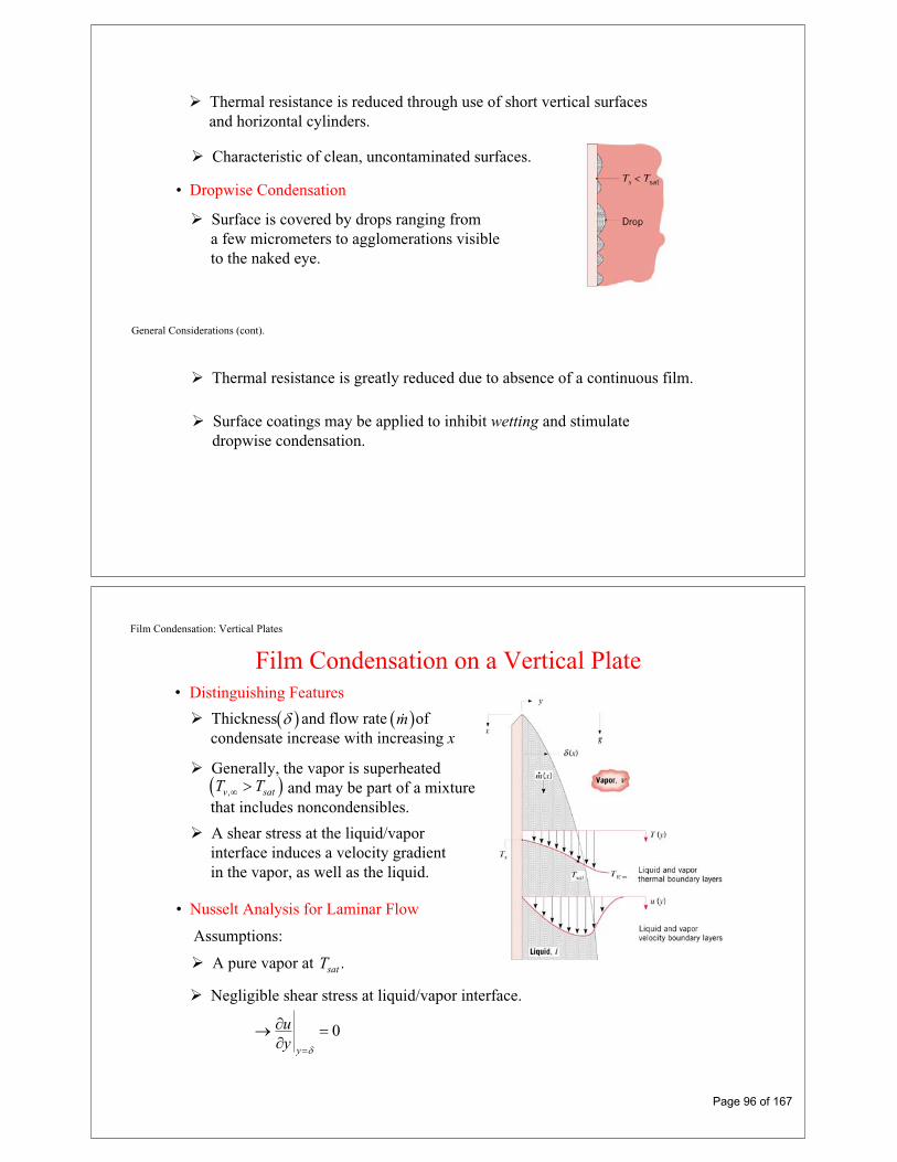
Thermal resistance is reduced through use of short vertical surfacesand horizontal cylinders.
Characteristic of clean, uncontaminated surfaces.
• Dropwise Condensation
Surface is covered by drops ranging froma few micrometers to agglomerations visibleto the naked eye.
General Considerations (cont).
Thermal resistance is greatly reduced due to absence of a continuous film.
Surface coatings may be applied to inhibit wetting and stimulatedropwise condensation.
Film Condensation: Vertical Plates
Film Condensation on a Vertical Plate• Distinguishing Features
Generally, the vapor is superheatedand may be part of a mixture
that includes noncondensibles.,v satT T
A shear stress at the liquid/vaporinterface induces a velocity gradientin the vapor, as well as the liquid.
• Nusselt Analysis for Laminar Flow
Assumptions:
A pure vapor at .satT
Negligible shear stress at liquid/vapor interface.
0y
uy
Thickness and flow rate of condensate increase with increasing x
m
Page 96 of 167

Vertical Plates (cont)
Negligible advection in the film. Hence, the steady-state x-momentum and energy equations for the film are
2
2
2
2
1
0
l
l l
gdpuy dx
Ty
The boundary layer approximation, may be applied to the film.0/ ,p yHence,
v
dpg
dx
Solutions to momentum and energy equations
Film thickness:1 4
4/
l l sat s
l l v fg
k T T xx
g h
Excerpts from this work may be reproduced by instructors for distribution on a not-for-profit basis for testing or instructional purposes onlyto students enrolled in courses for which the textbook has been adopted. Any other reproduction or translation of this work beyond that permitted by Sections 107 or 108 of the 1976 United States Copyright Act without the permission of the copyright owner is unlawful.
Page 97 of 167

Excerpts from this work may be reproduced by instructors for distribution on a not-for-profit basis for testing or instructional purposes onlyto students enrolled in courses for which the textbook has been adopted. Any other reproduction or translation of this work beyond that permitted by Sections 107 or 108 of the 1976 United States Copyright Act without the permission of the copyright owner is unlawful.
Page 98 of 167

University of Florida EML4140 §5964 Spring 2008
http://www.mae.ufl.edu/courses/spring2008/eml4140
EML4140 HEAT TRANSFER BLOCK III RADIATION
Page 99 of 167

Radiation: Processes and Properties-Basic Principles and Definitions-
Chapter 12
Sections 12.1 through 12.3
General Considerations
General Considerations• Attention is focused on thermal radiation, whose origins are associated
with emission from matter at an absolute temperature 0.T
• Emission is due to oscillations and transitions of the many electrons that comprisematter, which are, in turn, sustained by the thermal energy of the matter.
• Emission corresponds to heat transfer from the matter and hence to a reductionin thermal energy stored by the matter.
• Radiation may also be intercepted and absorbed by matter.
• Absorption results in heat transfer to the matter and hence an increase in thermal energy stored by the matter.
• Consider a solid of temperaturein an evacuated enclosure whose wallsare at a fixed temperature
sT
surT :
What changes occur if ? Why?s surT T
What changes occur if ? Why?s surT T
Page 100 of 167

General Considerations (cont)
• Emission from a gas or a semitransparent solid or liquid is a volumetricphenomenon. Emission from an opaque solid or liquid is a surface phenomenon.
For an opaque solid or liquid, emission originates from atoms and moleculeswithin 1 of the surface.m
• The dual nature of radiation:– In some cases, the physical manifestations of radiation may be explained
by viewing it as particles (aka photons or quanta).
– In other cases, radiation behaves as an electromagnetic wave.
General Considerations (cont)
– In all cases, radiation is characterized by a wavelength and frequencywhich are related through the speed at which radiation propagates in themedium of interest:
,
c
For propagation in a vacuum,82 998 10 m/soc c . x
Page 101 of 167

The EM Spectrum
The Electromagnetic Spectrum
• Thermal radiation is confined to the infrared, visible and ultraviolet regions of thespectrum . 01 100 m.
• The amount of radiation emitted by an opaque surface varies with wavelength, and we may speak of the spectral distribution over allwavelengths or of monochromatic/spectralcomponents associated with particular wavelengths.
Directional Considerations
Directional Considerations and theConcept of Radiation Intensity
• Radiation emitted by a surface will be in alldirections associated with a hypotheticalhemisphere about the surface and ischaracterized by a directional distribution.
• Direction may be represented in a sphericalcoordinate system characterized by the zenithor polar angle and the azimuthal angle .
2ndA
dr
ndA unit element of surface on a hypothetical sphere and normal tothe direction.,
• The amount of radiation emitted from a surface,and propagating in a particular direction,is quantified in terms of a differential
solid angle associated with the direction.
1dA ,, ,
Page 102 of 167

Directional Considerations (cont)
2 sinndA r d d
2 sinndAd d d
r
– The solid angle has units of steradians (sr).
– The solid angle associated with a complete hemisphere is2 2
0 0 2 srhemi d d/
sin
• Spectral Intensity: A quantity used to specify the radiant heat flux withina unit solid angle about a prescribed direction and within a unitwavelength interval about a prescribed wavelength
2W/m2W/m sr
2W/m sr m .
Directional Considerations (cont)
• The spectral intensity associated with emission from a surface element in the solid angle about and the wavelength interval aboutis defined as:
,eI 1dAd , d
1, , ,
cosedq
IdA d d
• The rationale for defining the radiation flux in terms of the projected surface areastems from the existence of surfaces for which, to a good approximation,
is independent of direction. Such surfaces are termed diffuse, and the radiation is said to be isotropic.
,eI1 cosdA
The projected area is how wouldappear if observed along .
1dA,
– What is the projected area for ?0
– What is the projected area for ?2/
• The spectral heat rate and heat flux associated with emission fromare, respectively,
1dA
1, , , cosedq
dq I dA dd
, ,, , cos , , cos sine edq I d I d d
Page 103 of 167

Radiation FluxesRelation of Intensity to Emissive Power,
Irradiation, and Radiosity• The spectral emissive power corresponds to spectral emission
over all possible directions.
2W/m m
2 2
0 0
/
, , , cos sineE I d d
• The total emissive power corresponds to emission over all directionsand wavelengths.
2W/m
0E E d
• For a diffuse surface, emission is isotropic and
,eE I eE I
• The spectral intensity of radiation incident ona surface, , is defined in terms of the unitsolid angle about the direction of incidence,the wavelength interval about ,and the projected area of the receivingsurface,
,iI
d
1 cos .dA
Radiation Fluxes (cont)
• The spectral irradiation is then:2W/m m2 2
0 0 iG I d d/
, , , cos sin
and the total irradiation is2W/m
0G G d
How may and G be expressed if the incident radiation is diffuse?G
• The radiosity of an opaque surface accounts for all of the radiation leaving the surface in all directions and may include contributions from both reflection andemission.
Page 104 of 167

Radiation Fluxes (cont)
• With designating the spectral intensity associated with radiationemitted by the surface and the reflection of incident radiation, the spectralradiosity is:
,e rI
2W/m m2 2
0 0 e rJ I d d/
, , , cos sin
and the total radiosity is2W/m
0J J d
How may and J be expressed if the surface emits and reflectsdiffusely?
J
The Blackbody
Blackbody Radiation• The Blackbody
An idealization providing limits on radiation emission and absorption by matter.
– For a prescribed temperature and wavelength, no surface can emit more radiation than a blackbody: the ideal emitter.
– A blackbody is a diffuse emitter.
– A blackbody absorbs all incident radiation: the ideal absorber.
• The Isothermal Cavity (Hohlraum).
(a) After multiple reflections, virtually all radiation entering the cavity is absorbed.
(b) Emission from the aperture is the maximum possible emission achievable forthe temperature associated with the cavity and is diffuse.
Page 105 of 167

The Blackbody (cont)
(c) The cumulative effect of radiation emission from and reflection offthe cavity wall is to provide diffuse irradiation corresponding to
emission from a blackbody for any surface in the cavity.bG E ,
– Does this condition depend on whether the cavity surface is highlyreflecting or absorbing?
Planck Distribution
The Spectral (Planck) Distribution of Blackbody Radiation• The spectral distribution of the blackbody emissive power (determined
theoretically and confirmed experimentally) is
15
2 1, ,, ,exp /b b
CE T I T
C T
First radiation constant: 8 4 21 3 742 10 W m mC . x /
Second radiation constant: 42 1 439 10 m KC . x
Page 106 of 167

Planck Distribution
varies continuously with and increases with T.,bE
The distribution is characterized by a maximum for which is given by Wien’s displacement law:
max
3 2898 m KmaxT C
The fractional amount of total blackbody emission appearing at lowerwavelengths increases with increasing T.
Stefan-Boltzmann Law
The Stefan-Boltzmann Law and Band Emission• The total emissive power of a blackbody is obtained by integrating the Planck
distribution over all possible wavelengths.
40b b bE I E d T,
the Stefan-Boltzmann law, where8 2 4 the Stefan-B5 670 10 W/m oltzmann K constant. x
• The fraction of total blackbody emission that is in a prescribed wavelengthinterval or band is1 2
2 1
1 2 2 1
00 0 4
b o bE d E dF F F
T, ,
where, in general,
00
bE dF f T
T,
and numerical results are given in Table 12.1
Page 107 of 167

Band Emission
• Table 12.1
. . . .
. . . .
. . . .
Band Emission (cont)
Note ability to readily determine and its relation to the maximum intensity fromthe 3rd and 4th columns, respectively.
,bI
If emission from the sun may be approximated as that from a blackbody at5800 K, at what wavelength does peak emission occur?Would you expect radiation emitted by a blackbody at 800 K to be discernibleby the naked eye?
As the temperature of a blackbody is increased, what color would bethe first to be discerned by the naked eye?
Page 108 of 167

Problem: Solar Irradiation
Problem 12.6: Evaluation of total solar irradiation at the earth’s surfacefrom knowledge of the direct and diffuse components of the incident radiation.
KNOWN: Flux and intensity of direct and diffuse components, respectively, of solar irradiation
FIND: Total irradiation.
Problem: Solar Irradiation
SCHEMATIC:
ANALYSIS: Since the irradiation is based on the actual surface area, the contribution due to the direct solar radiation is
dir dirG q cos .
For the contribution due to the diffuse radiation
dif difG I .
Hence
dir dif dir difG G G q cos I
Page 109 of 167

Problem: Solar Irradiation
or
2 2G 1000 W / m 0.866 sr 70 W / m sr
2G 866 220 W / m
2G 1086 W / m .
COMMENTS: Although a diffuse approximation is often made for the non-direct component of solar radiation, the actual directional distribution deviates from this condition, providing larger intensities at angles close to the direct beam.
Problem: Solar/Earth Temperatures
Problem 12.20: Determination of the sun’s emissive power, temperatureand wavelength of maximum emission, as well as theearth’s temperature, from knowledge of the sun/earthgeometry and the solar flux at the outer edge of the earth’satmosphere.
KNOWN: Solar flux at outer edge of earth’s atmosphere, 1353 W/m2.
FIND: (a) Emissive power of sun, (b) Surface temperature of sun, (c) Wavelength of maximum solar emission, (d) Earth equilibrium temperature.
SCHEMATIC:
Page 110 of 167

Problem: Solar/Earth Temperatures (cont)
ASSUMPTIONS: (1) Sun and earth emit as blackbodies, (2) No attenuation of solar radiation enroute to earth, (3) Earth atmosphere has no effect on earth energy balance.
ANALYSIS: (a) Applying conservation of energy to the solar energy crossing two concentric spheres, one having the radius of the sun and the other having the radial distance from the edge of the earth’s atmosphere to the center of the sun, it follows that
s
22 e
s s s eD
E D 4 R q .2
Hence 211 7 2
7 2s 29
4 1.5 10 m 0.65 10 m 1353 W / mE 6.302 10 W / m .
1.39 10 m
(b) From the Stefan-Boltzmann law, the temperature of the sun is
1/ 41/ 4 7 2s
s 8 2 4E 6.302 10 W / m
T 5774 K.5.67 10 W / m K
(c) From Wien’s displacement law, the wavelength of maximum emission is
3max
C 2898 m K0.50 m.
T 5774 K
Problem: Solar/Earth Temperatures (cont)
Hence, from the Stefan-Boltzmann law,
S1/ 41/ 4 2
e 8 2 4
q 1353 W / mT 278 K.
4 4 5.67 10 W / m K
COMMENTS: The average earth temperature is higher than 278 K due to the shielding effect of the earth’s atmosphere (transparent to solar radiation but not to longer wavelength earth emission).
(d) From an energy balance on the earth’s surface
2 2e e S eE D q D / 4 .
Page 111 of 167

Radiation: Processes and PropertiesSurface Radiative Properties
Chapter 12
Sections 12.4 through 12.7
EmissivitySurface Emissivity
• Radiation emitted by a surface may be determined by introducing a property (the emissivity) that contrasts its emission with the ideal behavior of a blackbodyat the same temperature.
• The definition of the emissivity depends upon one’s interest in resolvingdirectional and/or spectral features of the emitted radiation, in contrastto averages over all directions (hemispherical) and/or wavelengths (total).
• The spectral, directional emissivity:
,,
,
, , ,, , ,
,e
b
I TT
I T
• The spectral, hemispherical emissivity (a directional average):2 20 0
2 20 0
/,
/, ,
, , , cos sin,,
, , cos sine
b b
I T d dE TT
E T I T d d
Page 112 of 167

Emissivity (cont)
• The total, hemispherical emissivity (a directional and spectral average):
0 b
b b
T E T dE TT
E T E T,, , ,
• To a reasonable approximation, the hemispherical emissivity is equal tothe normal emissivity.
n
• Representative values of the total, normal emissivity:
Note:Low emissivity of polished metals and increasing emissivity for unpolishedand oxidized surfaces.Comparatively large emissivities of nonconductors.
Emissivity (cont)
• Representative spectral variations:
Note decreasing with increasing for metals and different behavior for nonmetals.,n
• Representative temperature variations:
nWhy does increase with increasing for tungsten and not for aluminum oxide?
Page 113 of 167

Abs, Ref & Trans
Response to Surface Irradiation: Absorption, Reflectionand Transmission
• There may be three responses of a semitransparent medium to irradiation:
Reflection from the medium refG , .
Absorption within the medium absG , .
Transmission through the medium trG , .
Radiation balance
ref abs trG G G G, , ,
• In contrast to the foregoing volumetric effects, the response of an opaque materialto irradiation is governed by surface phenomena and 0, .trG
, ,ref trG G G
• The wavelength of the incident radiation, as well as the nature of the material,determine whether the material is semitransparent or opaque.
Are glass and water semitransparent or opaque?
Abs, Ref & Trans (cont)
• Unless an opaque material is at a sufficiently high temperature to emit visibleradiation, its color is determined by the spectral dependence of reflection inresponse to visible irradiation.
What may be said about reflection for a white surface? A black surface?
Why are leaves green?
Page 114 of 167

Absorptivity
Absorptivity of an Opaque Material• The spectral, directional absorptivity:
, ,,
,
, ,, ,
, ,i abs
i
I
I
• The spectral, hemispherical absorptivity:2 20 0
2 20 0
/, , ,
/,
, , , , cos sin, , cos sin
abs i
i
G I d d
G I d d
To what does the foregoing result simplify, if the irradiation is diffuse?
If the surface is diffuse?
• The total, hemispherical absorptivity:
0
oabs G dGG G d
If the irradiation corresponds to emission from a blackbody, how may the above expression be rewritten?
Assuming negligible temperature dependence,
The absorptivity is approximately independent of the surface temperature,but if the irradiation corresponds to emission from a blackbody, why doesdepend on the temperature of the blackbody?
Reflectivity
Reflectivity of an Opaque Material• The spectral, directional reflectivity: Assuming negligible temperature
dependence:
, ,,
,
, ,, ,
, ,i ref
i
I
I
• The spectral, hemispherical reflectivity:22
0 0
/, , ,
,
, , , , cos sin, ,
ref i
i
G I d d
G I
To what does the foregoing result simplify if the irradiation is diffuse?
If the surface is diffuse?
• The total, hemispherical reflectivity:
0
0
refG G d
G G d
• Limiting conditions of diffuse andspecular reflection.Polished and rough surfaces.
Page 115 of 167

Reflectivity (cont)
Note strong dependence of and 1 on .
Is snow a highly reflective substance? White paint?
Transmissivity Transmissivity
• The spectral, hemispherical transmissivity: Assuming negligible temperature dependence,
,trG
G
Note shift from semitransparent to opaque conditions at large and small wavelengths.
• The total, hemispherical transmissivity:
0
0
trtr G dGG G d
,
• For a semitransparent medium,
11
Page 116 of 167

Kirchhoff’s Law
• Kirchhoff’s law equates the total, hemispherical emissivity of a surface to itstotal, hemispherical absorptivity:
Kirchhoff’s Law
However, conditions associated with its derivation are highly restrictive:
Irradiation of the surface corresponds to emission from a blackbody at thesame temperature as the surface.
• However, Kirchhoff’s law may be applied to the spectral, directional propertieswithout restriction:
, ,
Why are there no restrictions on use of the foregoing equation?
Diffuse/Gray Surfaces
Diffuse/Gray Surfaces• With 2 2
0 02 20 0
/,
/
cos sincos sin
d d
d d
and 2 20 0
2 20 0
/, ,
/,
cos sincos sin
i
i
I d d
I d d
Under what conditions may we equate to ?
• With0 b
b
E d
E T,
and0 G d
GUnder what conditions may we equate to ?
• Conditions associated with assuming a gray surface:
Page 117 of 167

Problem: Surface Emissivity and Absorptivity
Problem 12.49: Determination of the solar absorptivity and total emissivityof a diffuse surface from knowledge of the spectraldistribution of and the surface temperature.
KNOWN: Spectral, hemispherical absorptivity of an opaque surface.
FIND: (a) Solar absorptivity, (b) Total, hemispherical emissivity for Ts = 340 K.
Problem: Surface Emissivity and Absorptivity (cont)
SCHEMATIC:
ASSUMPTIONS: (1) Surface is opaque, (2) = , (3) Solar spectrum has G = G ,S
proportional to E ,b ( , 5800 K).
ANALYSIS: (a) The solar absorptivity may be expressed as
S ,b ,b0 0E ,5800K d / E ,5800K d .
The integral can be written in three parts using F(0 ) terms.
S 1 2 30 0.3 m 0 1.5 m 0 0.3 m 0 1.5 mF F F 1 F .
From Table 12.1,
T = 0.3 5800 = 1740 m K F(0 0.3 m) = 0.0335 T = 1.5 5800 = 8700 m K F(0 1.5 m) = 0.8805.
Page 118 of 167

Problem: Surface Emissivity and Absorptivity (cont)
Hence,
S 0 0.0355 0.9 0.8805 0.0335 0.1 1 0.8805 0.774.
(b) The total, hemispherical emissivity for the surface at 340 K may be expressed as
,b b0E ,340K d / E 340K .
With = , the integral can be written in terms of the F(0 ) function. However, it is readily recognized that since
0 1.5 m,340KF 0.000 at T 1.5 340 510 m K
there is negligible emission below 1.5 m.
It follows that
0.1
COMMENTS: The assumption = is satisfied if the surface is irradiated diffusely or if the surface itself is diffuse. Note that for this surface under the specified conditions of solar irradiation and surface temperature, S . Such a surface is spectrally selective.
Problem: Energy Balance for an Irradiated Surface
Problem 12.101: Determination of the minimum value of the outsideconvection coefficient on a ceramic plate to maintainprescribed plate temperature, and the sensitivity of theplate temperature to the outside convection coefficient.
KNOWN: Temperature of interior wall of a furnace and the surroundings.Spectral distribution of plate absorptivity. Specified maximum plate temperature.
FIND: (a) Value of the outside convection coefficient, ho, to maintain plate at Ts = 1800 K. (b) Plate temperature for various values of ho.
Page 119 of 167

Problem: Energy Balance for an Irradiated Surface (cont)
SCHEMATIC:
Furnace wall
Surroundings
Ts
q"conv
E
E
wGw
surGsur
Tw = 2400 K Tsur = 300 K
h, T = 300 K
=
0.3
0.8
( m)c = 3
1 = 1
2 = 2
Furnace wall
Surroundings
Ts
q"conv
E
E
wGw
surGsur
Tw = 2400 K Tsur = 300 K
h, T = 300 K
=
0.3
0.8
( m)c = 3
=
0.3
0.8
( m)c = 3
1 = 1
2 = 2
ASSUMPTIONS: (1) Steady-state conditions, (2) Plate is opaque and diffuse, (3) Negligible temperature gradient in the plate, (4) Negligible convection oninterior surface of plate, (5) Furnace cavity and surroundings are large.
Problem: Energy Balance for an Irradiated Surface (cont)
ANALYSIS: (a) Perform an energy balance on the plate as shown in the schematic.
in outE E 0
"w w sur sur convG G 2E q 0
4 4 4w w sur sur s o sT T 2 T h (T T ) 0
or
4 4 4w w sur sur s
os
T T 2 Th
(T T )
where from Table 12.1, with cTs = 3 m 1800 K = 5400 m·K, c s(0 T )F 0.6804.
where w, sur, and are determined from = .
Plate total emissivity: Expressing the emissivity in terms of the band emission factor, F(0 – T),
c s c s1 (0 T ) 2 (0 T )F 1 F
0.3 0.6804 0.8 1 0.6804 0.460
Page 120 of 167

Problem: Energy Balance for an Irradiated Surface (cont)
Plate total absorptivity to irradiation from the furnace:
c w c ww 1 (0 T ) 2 (0 T )F 1 F
w 0.3 0.8192 0.8 1 0.8912 0.390
where from Table 12.1, with cTw = 3 m 2400 K = 7200 m·K, c w(0 T )F 0.8192.
Plate total absorptivity to irradiation from the surroundings:
c s c ssur 1 (0 T ) 2 (0 T )F 1 F
sur 0.3 0 0.8 1 0 0.800
where from Table 12.1, with cTsur = 3 m 300 K = 900 m·K, c sur(0 T )F 0.0.
Problem: Energy Balance for an Irradiated Surface (cont)
Therefore,
8 2 4 4 4 4
o
5.67 10 W / m K 0.390 (2400 K) 0.800 (300 K) 2 0.460 (1800 K)h
(1800 300) K
2oh 125 W / m K <
50 100 150 200 250
Convection coefficient, ho(W/m^2.K)
1600
1700
1800
1900
Tem
pera
ture
, T(K
)
(b)
Page 121 of 167

Problem: Energy Balance for an Irradiated Surface (cont)
With increasing values of ho, the plate temperature is reduced. <
COMMENTS: (1) The plate is not gray. (2) The required value of the exterior heat transfer coefficient is easily obtainable with air cooling. (3) The gas inside the furnace may heat or cool the plate by convection, depending whether the gas temperature is greater or less than the plate temperature.
Radiation Exchange Between Surfaces:Enclosures with Nonparticipating Media
Chapter 13
Sections 13.1 through 13.3
Page 122 of 167

Basic Concepts
Basic Concepts
• Enclosures consist of two or more surfaces that envelop a region of space (typically gas-filled) and between which there is radiation transfer.
• A nonparticipating medium within the enclosure neither emits, absorbs,nor scatters radiation and hence has no effect on radiation exchangebetween the surfaces.
• Each surface of the enclosure is assumed to be isothermal, opaque, diffuseand gray, and to be characterized by uniform radiosity and irradiation.
Virtual,as well as real, surfaces may be introduced to form an enclosure.
View Factor Integral
The View Factor (also Configuration or Shape Factor)• The view factor, is a geometrical quantity corresponding
to the fraction of the radiation leaving surface i that is intercepted by surface j.
,ijF
i jij
i i
qF
A J
• The view factor integral provides a general expression for .ijF Consider exchangebetween differential areas i :jdA and dA
21 cos cos
i j
i jij i jA A
i
F dA dAA R
2
cos coscos i j
i j i i i j i i i jdq I dA d J dA dAR
Page 123 of 167

View Factor Relations
View Factor Relations• Reciprocity Relation. With
21 cos cos
ji
i jji i jAA
j
F dA dAA R
• Summation Rule for Enclosures.
11
N
ijj
F
• Two-Dimensional Geometries (Table 13.1) For example,
An Infinite Plane and a Row of Cylinders
1 2 1 22 2 21
21 1ijD D s DFs s D
/ /
tan
i ij j jiA F A F
View Factor Relations (cont)
• Three-Dimensional Geometries (Table 13.2). For example,
Coaxial Parallel Disks
1 222
2
2
1 42
11
//
/ /
ij j i
j
i
i i j j
F S S r r
RS
R
R r L R r L
Page 124 of 167

Blackbody Enclosure
Blackbody Radiation Exchange• For a blackbody, .i biJ E
ij i j j iq q q
ij i ij bi j ji bjq A F E A F E
4 4ij i ij i jq A F T T
net rate at which radiationleaves surface i due to itsinteraction with j
or net rate at which surfacej gains radiation due to itsinteraction with i
• Net radiation transfer from surface i due to exchange with all (N)surfaces of an enclosure:
4 4
1
N
i i ij i jj
q A F T T
• Net radiative exchange between twosurfaces that can be approximated asblackbodies
General Enclosure Analysis
General Radiation Analysis for Exchange between the NOpaque, Diffuse, Gray Surfaces of an Enclosure
1i i i
• Alternative expressions for net radiativetransfer from surface i:
Fig. (b)i i i iq A J G (1)
Fig. (c)i i i i iq A E G (2)
Fig. (d)1 /
bi ii
i i i
E Jq
A(3)
Suggests a surface radiativeresistance of the form: 1 /i i iA
Page 125 of 167

General Enclosure Analysis (cont)
11 1
N N i ji i ij i j
j ji ij
J Jq A F J J
A F (4)
Suggests a space or geometricalresistance of the form:
1
i ijA F
• Equating Eqs. (3) and (4) corresponds to a radiation balance on surface i:
111 /
N i jbi i
ji i i i ij
J JE JA A F
(5)
which may be represented by a radiation network of the form
General Enclosure Analysis (cont)
• Methodology of an Enclosure Analysis
Apply Eq. (4) to each surface for which the net radiation heat rate is known.iq
Apply Eq. (5) to each of the remaining surfaces for which the temperature ,and hence is known.
iT,biE
Evaluate all of the view factors appearing in the resulting equations.
Solve the system of N equations for the unknown radiosities, 1 2, ,...., .NJ J J
Use Eq. (3) to determine for each surface of known for each surface of known .
iq andi iT T
iq
• Treatment of the virtual surface corresponding to an opening (aperture) of area ,through which the interior surfaces of an enclosure exchange radiation with largesurroundings at :
iA
surT
Approximate the opening as blackbody of area, temperature,and properties, .
,iA ,i surT T1i i
Page 126 of 167
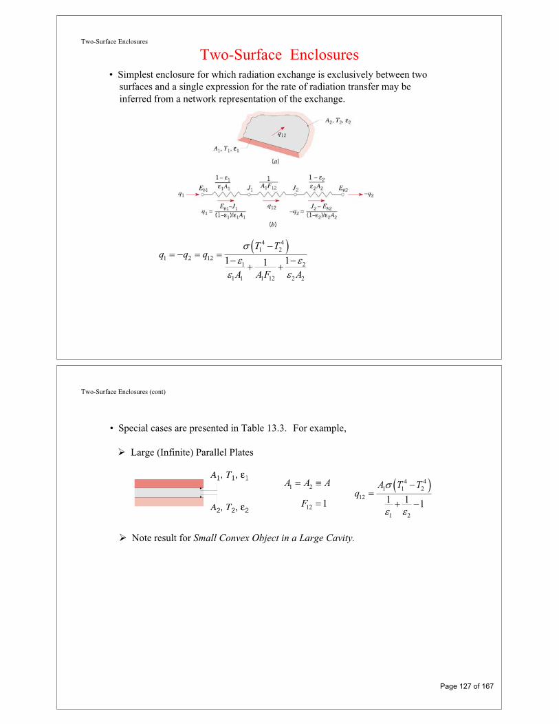
Two-Surface Enclosures
Two-Surface Enclosures• Simplest enclosure for which radiation exchange is exclusively between two
surfaces and a single expression for the rate of radiation transfer may beinferred from a network representation of the exchange.
4 41 2
1 2 121 2
1 1 1 12 2 2
1 11
T Tq q q
A A F A
Two-Surface Enclosures (cont)
• Special cases are presented in Table 13.3. For example,
Large (Infinite) Parallel Plates
1 2
12 1
A A A
F
4 41 1 2
12
1 2
1 1 1
A T Tq
Note result for Small Convex Object in a Large Cavity.
Page 127 of 167

Radiation Shield
Radiation Shields• High reflectivity (low ) surface(s) inserted between two surfaces for which
a reduction in radiation exchange is desired.
• Consider use of a single shield in a two-surface enclosure, such as that associated withlarge parallel plates:
Note that, although rarely the case, emissivities may differ for opposite surfacesof the shield.
Radiation Shield (cont)
• Radiation Network:
4 41 2
12 1 23 1 3 21 2
1 1 1 13 3 1 3 3 2 3 3 32 2 2
1 11 11 1, ,
, ,
T Tq q q
A A F A A A F A
• The foregoing result may be readily extended to account for multiple shieldsand may be applied to long, concentric cylinders and concentric spheres,as well as large parallel plates.
Page 128 of 167

Reradiating Surfaces
The Reradiating Surface• An idealization for which .R RG J Hence, and 0 .R R bRq J E
• Approximated by surfaces that are well insulated on one side and for whichconvection is negligible on the opposite (radiating) side.
• Three-Surface Enclosure with a Reradiating Surface:
4 41 2
1 21 2
11 1 2 21 12 1 1 2 2
1 111 1/ /R R
T Tq q
A AA F A F A F
Reradiating Surfaces (cont)
• Temperature of reradiating surface may be determined from knowledgeof its radiosity .
RT
RJ With , a radiation balance on the surface yields0Rq
1 2
1 1 2 21 1/ /R R
R R
J J J JA F A F
1 4/R
R
JT
Page 129 of 167

Multimode Effects
Multimode Effects• In an enclosure with conduction and convection heat transfer to or from
one or more surfaces, the foregoing treatments of radiation exchange may be combined with surface energy balances to determine thermal conditions.
• Consider a general surface condition for which there is external heat addition(e.g., electrically), as well as conduction, convection and radiation.
, , , ,i ext i rad i conv i radq q q q
Appropriate analysis for -surface, two-surface, etc., enclosure.,i radq N
Problem: Furnace in Spacecraft Environment
Problem 13.88: Power requirement for a cylindrical furnace with tworeradiating surfaces and an opening to large surroundings.
KNOWN: Cylindrical furnace of diameter D = 90 mm and overall length L = 180 mm. Heating elements maintain the refractory lining ( = 0.8) of section (1), L1 = 135 mm, at T1 = 800 C. The bottom (2) and upper (3) sections are refractory lined, but are insulated. Furnace operates in a spacecraft vacuum environment.
FIND: Power required to maintain the furnace operating conditions with the surroundings at 23 C.
Page 130 of 167

Problem: Furnace in Spacecraft Environment (cont)
SCHEMATIC:
ASSUMPTIONS: (1) All surfaces are diffuse gray, and (2) Uniform radiosity over the sections 1, 2, and 3.
ANALYSIS: By defining the furnace opening as the hypothetical area A4, the furnace can be represented as a four-surface enclosure.
The power required to maintain A1 at T1 is q1, the net radiation leaving A1.
To obtain q1, we must determine the radiosity at each surface by simultaneously solving radiation energy balance equations of the form
Nj jbi i
ii i i i ijj 1
J JE Jq
1 / A 1/ A F (1,2)
Problem: Furnace in Spacecraft Environment (cont)
However, since 4 = 1, J4 = Eb4, and only three energy balances are needed for A1, A2, and A3.
A1: b1 1 1 31 2 1 4
1 1 1 1 12 1 13 1 14
E J J JJ J J J
1 / A 1/ A F 1/ A F 1/ A F (3)
A2: 2 32 1 2 4
2 21 2 23 2 24
J JJ J J J0
1/ A F 1/ A F 1/ A F (4)
A3: 3 1 3 2 3 4
3 31 3 32 3 34
J J J J J J0
1/ A F 1/ A F 1/ A F (5)
where q2 = q3 = 0 since the surfaces are insulated (adiabatic) and hence reradiating.
From knowledge of J1, q1 can be determined using Eq. (1).
Of the N2 = 42 = 16 view factors, N(N – 1)/2 = 6 must be independently evaluated, while the remaining can be determined by the summation rule and appropriate reciprocity relations. The six independently determined Fij are:
By inspection: (1) F22 = 0 (2) F44 = 0
Page 131 of 167

Problem: Furnace in Spacecraft Environment (cont)
Coaxial parallel disks: From Table 13.2,
(3)1/ 222
24 4 2F 0.5 S S 4 r / r 0.05573
where 2 24
2 2 4 42 22
1 R 1 0.250S 1 1 18.00 R r / L 45 /180 0.250 R r / L 0.250
R 0.250
Enclosure 1-2-2 : From the summation rule for A2,
(4) F21 = 1 – F22 = 1 – 0.09167 = 0.9083 where F22 can be evaluated from the coaxial parallel disk relation, Table 13.2, with R2 = r2/L1 =45/135 = 0.333, R2 = r2/L1 = 0.333, and S = 11.00.
From the summation rule for A1,
(5) F11 = 1 – F12 – F12 = 1 – 0.1514 – 0.1514 = 0.6972
From symmetry F12 = F12 and using reciprocity
12 2 21 12F A F / A 0.090m 0.9083 / 0.090m 0.135m 0.1514/ 4
Enclosure 2 -3-4: From the summation rule for A4,
(6) F43 = 1 – F42 – F44 = 1 – 0.3820 – 0 = 0.6180
where F44 = 0 and using the coaxial parallel disk relation from Table 13.2, F42 =0.3820 with R4 =
r4/L2 = 45/45 = 1, R2 = r2/L2 = 1, and S = 3.
Problem: Furnace in Spacecraft Environment (cont)
From knowledge of the relevant view factors, the energy balances, Eqs. (3, 4, 5), can be solved simultaneously to obtain the radiosities,
2 2 21 2 3J 73,084 W / m J 67,723W / m J 36,609 W / m
The net heat rate leaving A1 can be evaluated using Eq. (1) written as 2
b1 11 21 1 1
75,159 73,084 W / mE Jq 317 W
1 / A 1 0.8 / 0.8 0.03817 m <
where Eb1 = 41T = (800 + 273K)4 = 75,159 W/m2 and A1 = DL1 = 0.090m 0.135m =
0.03817 m2.
COMMENTS: Recognize the importance of defining the furnace opening as the hypothetical area A4 which completes the four-surface enclosure representing the furnace. The temperature of A4 is that of the surroundings and its emissivity is unity since it absorbs all radiation incident on it.
The View Factors: Using summation rules and appropriate reciprocity relations, the remaining 10 view
factors can be evaluated. Written in matrix form, the Fij are 0.6972* 0.1514 0.09704 0.05438 0.9083* 0* 0.03597 0.05573* 0.2911 0.01798 0.3819 0.3090 0.3262 0.05573 0.6180* 0*
The Fij shown with an asterisk were independently determined.
Page 132 of 167

Problem 13.93
Problem 13.93: Assessment of ceiling radiative properties for an ice rinkin terms of ability to maintain surface temperature above the dew point.
KNOWN: Ice rink with prescribed ice, rink air, wall, ceiling and outdoor air conditions.
FIND: (a) Temperature of the ceiling, Tc, for an emissivity of 0.05 (highly reflective panels) or 0.94 (painted panels); determine whether condensation will occur for either or both ceiling panel types if the relative humidity of the rink air is 70%, and (b) Calculate and plot the ceiling temperature as a function of ceiling insulation thickness for 0.1 t 1 m; identify conditions for which condensation will occur on the ceiling.
Problem 13.93 (cont)
SCHEMATIC:
ASSUMPTIONS: (1) Rink comprised of the ice, walls and ceiling approximates a three-surface, diffuse-gray enclosure, (2) Surfaces have uniform radiosities, (3) Ice surface and walls are black, (4) Panels are diffuse-gray, and (5) Thermal resistance for convection on the outdoor side of the ceiling is negligible compared to the conduction resistance of the ceiling insulation.
Page 133 of 167

Problem 13.93 (cont)
PROPERTIES: Psychrometric chart (Atmospheric pressure; dry bulb temperature, Tdb = T ,i
= 15 C; relative humidity, RH = 70%): Dew point temperature, Tdp = 9.4 C.
ANALYSIS: Applying an energy balance to the inner surface of the ceiling and treating all heat rates as energy outflows,
E Ein out 0q q qo conv,c rad,c 0 (1)
From Table 13.2 for parallel, coaxial disks Fic 0 672.
From the summation rule applied to the ice (i) and the reciprocity rule, F F F F (symmetry)ic iw iw cw1F Fcw ic1
F A A F A A 1 Fwc c w cw c w ic/ / .b g b g b g 0 410
where Ac = D2/4 and Aw = DL.
where the rate equations for each process are
o c ,o cond cond cq T T / R R t / kA (2,3)
conv,c i c c ,iq h A T T (4)
Since the ceiling panels are diffuse-gray, = .
q E T A A F E T A F E Trad,c b c c w wc b w i ic b ib g b g b g (5)
Problem 13.93 (cont)
Using the foregoing energy balance, Eq. (1), and the rate equations, Eqs. (2-5), the ceiling temperature is calculated using radiative properties for the two panel types,
Ceiling panel Tc ( C)
Reflective 0.05 14.0 Paint 0.94 8.6 Tc < Tdp <
. Condensation will occur on the painted panel since Tc < Tdp.
(b) Applying the foregoing model for 0 1 1 0 m. . ,t the following result is obtained
0 0.2 0.4 0.6 0.8 1
Ceiling insulation thickness, t (m)
5
10
15
Cei
ling
tem
pera
ture
, Tc
(C)
Painted ceiling, epsc = 0.94Reflective panel, epsc = 0.05
Page 134 of 167

Problem 13.93 (cont)
For the reflective panel ( = 0.05), the ceiling surface temperature is considerably above the dew point. Therefore, condensation will not occur for the range of insulation thicknesses. For the painted panel ( = 0.94), the ceiling surface temperature is always below the dew point, and condensation occurs for the range of insulation thicknesses.
COMMENTS: From the analysis, recognize that radiative exchange between the ice and the ceiling has the dominant effect on the ceiling temperature. With the reflective panel, the rate is reduced nearly 20-fold relative to that for the painted panel. With the painted panel ceiling, condensation will occur for most of the conditions likely to exist in the rink.
Page 135 of 167

Page 136 of 167
University of Florida EML4140 §5964 Spring 2008
http://www.mae.ufl.edu/courses/spring2008/eml4140
SELECTEDANSWERS
FUNDAMENTALS OF HEAT ANDMASS TRANSFER
Page 137 of 167

ANSWERS TO END-OF-CHAPTER PROBLEMSFundamentals of Heat and Mass Transfer (6th Edition)
Introduction to Heat Transfer (5th Edition)F.P. Incropera
D.P. DeWittT.L. Bergman
A.S. Lavine
CHAPTER 1
1.1 14.5 W/m2, 58 W1.2 2667 W1.3 4312 W, $4.14/d 1.4 0.10 W/m K1.5 8400 W 1.6 19,600 W, 120 W 1.7 54 mm1.8 16.6 W/m2, 35.9 W 1.9 375 mm 1.10 110.40°C, 110.24C 1.11 1.1°C 1.12 (a) 9800 W/m2
1.13 (a) 1400 W/m2; (b) 18,000 W/m2
1.14 (a) 22.0 W/m2 K; (b) 22.12, 0.6 1.15 4570 W/m2 K, 65 W/m2 K1.16 51.8°C, 3203 C1.17 6.3 m/s 1.18 0.35 W, 5.25 W 1.19 2.94 W 1.21 15 mW 1.22 6.3 W/m2 K1.23 102.5°C 1.25 254.7 K 1.27 0.42, 264 W1.28 (a) 18,405 W; (b) $6450 1.30 3.5% 1.31 (a) 0.223 W; (b) 3.44 W1.32 (a) 8.1 W; (b) 0.23 kg/h 1.33 100°C 1.34 (a) 0, 144 W, 144 W, 0; 0, 144 W, 144 W, 0; (b) 2.04 105 W/m3; (c) 39.0 W/m2 K1.35 (a) 0.052°C/s; (b) 48.4°C 1.36 375 W, 1.8 10-4 W, 0.065 W1.37 6380 kWh, $510 or $170 1.38 (a) 4180 s; (b) 319 K, 359 K; (c) 830 K
Page 138 of 167
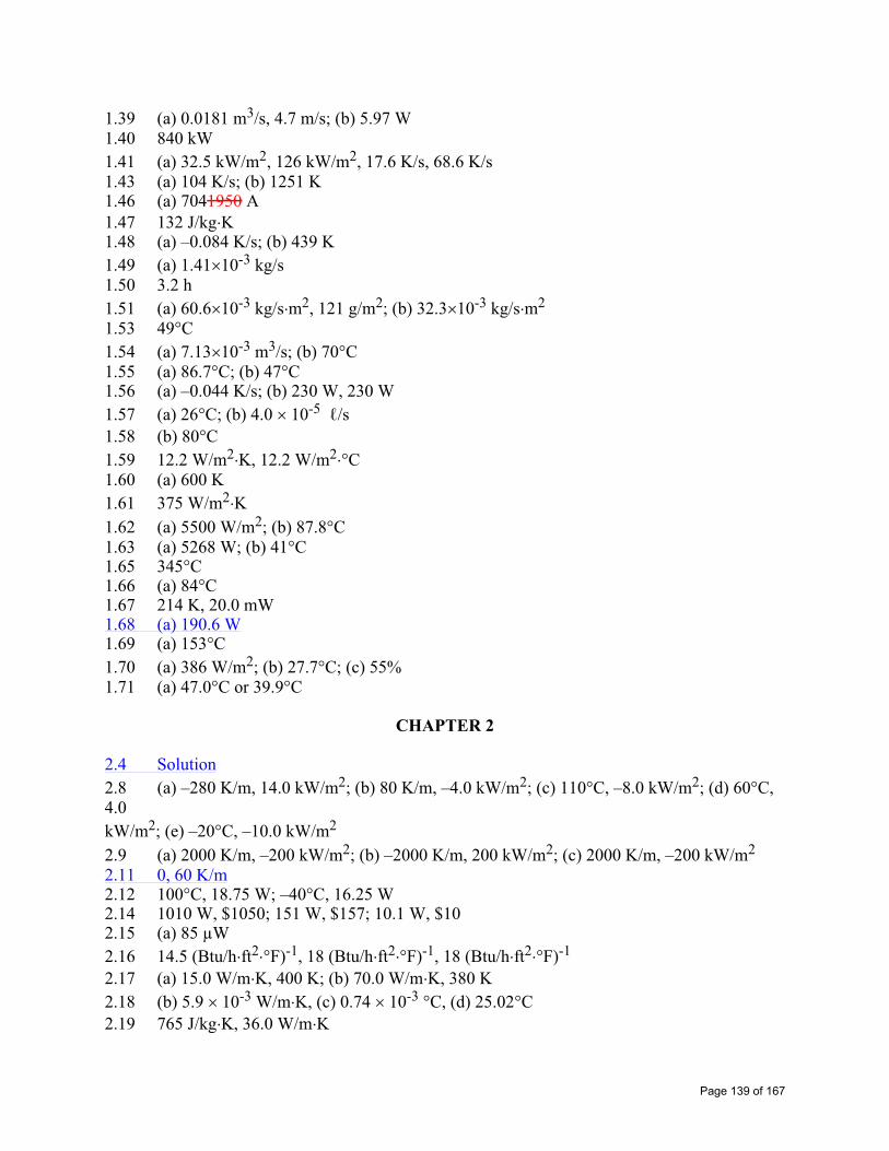
1.39 (a) 0.0181 m3/s, 4.7 m/s; (b) 5.97 W 1.40 840 kW 1.41 (a) 32.5 kW/m2, 126 kW/m2, 17.6 K/s, 68.6 K/s 1.43 (a) 104 K/s; (b) 1251 K 1.46 (a) 7041950 A 1.47 132 J/kg K1.48 (a) –0.084 K/s; (b) 439 K 1.49 (a) 1.41 10-3 kg/s 1.50 3.2 h 1.51 (a) 60.6 10-3 kg/s m2, 121 g/m2; (b) 32.3 10-3 kg/s m2
1.53 49°C 1.54 (a) 7.13 10-3 m3/s; (b) 70°C 1.55 (a) 86.7°C; (b) 47°C 1.56 (a) –0.044 K/s; (b) 230 W, 230 W1.57 (a) 26 C; (b) 4.0 10-5 /s1.58 (b) 80 C1.59 12.2 W/m2 K, 12.2 W/m2 C1.60 (a) 600 K 1.61 375 W/m2 K1.62 (a) 5500 W/m2; (b) 87.8°C 1.63 (a) 5268 W; (b) 41°C 1.65 345°C 1.66 (a) 84°C 1.67 214 K, 20.0 mW 1.68 (a) 190.6 W1.69 (a) 153°C 1.70 (a) 386 W/m2; (b) 27.7°C; (c) 55% 1.71 (a) 47.0°C or 39.9°C
CHAPTER 2
2.4 Solution2.8 (a) –280 K/m, 14.0 kW/m2; (b) 80 K/m, –4.0 kW/m2; (c) 110°C, –8.0 kW/m2; (d) 60°C, 4.0kW/m2; (e) –20°C, –10.0 kW/m2
2.9 (a) 2000 K/m, –200 kW/m2; (b) –2000 K/m, 200 kW/m2; (c) 2000 K/m, –200 kW/m2
2.11 0, 60 K/m2.12 100°C, 18.75 W; –40°C, 16.25 W 2.14 1010 W, $1050; 151 W, $157; 10.1 W, $102.15 (a) 85 μW2.16 14.5 (Btu/h ft2 F)-1, 18 (Btu/h ft2 F)-1, 18 (Btu/h ft2 F)-1
2.17 (a) 15.0 W/m K, 400 K; (b) 70.0 W/m K, 380 K 2.18 (b) 5.9 10-3 W/m K, (c) 0.74 10-3 C, (d) 25.02 C2.19 765 J/kg K, 36.0 W/m K
Page 139 of 167

2.22 (a) 0, 0.98 105 W/m; (b) 56.8 K/s 2.23 (a) 2 105 W/m3; (b) 0, 10,000 W/m2
2.24 (a) 200 W/m2, 182 W/m2, 18 W/m2; (b) 4.3 W/m2 K2.25 (b) 2 105 W/m3; (c) –2950 W/m2, 5050 W/m2; (d) 51 W/m2 K, 101 W/m2 K; (f) –2 105
W/m3; (g) 20°C, 4.94 106 J/m2
2.26 (a) 106 W/m3; (b) 120°C, 104 K/m, –105 K/m2; (c) 220°C, 104 K/m, –105 K/m2; (d) 220°C, 2 104 K/m, –2 105 K/m2
2.40 (a) 0.20 m; (b) 0; (c) –144,765 W; (d) 72,380 W, –72,380 W 2.41 (d) 133°C, 122°C, 133.1°C 2.43 (d) 52.5°C2.45 (c) 18.0 kW/m2, –360 K/m; (d) 8.73 106 J/m2; (e) 8.73 106 J/m2
2.51 (a) 1.8 106 W/m3; (c) 1.8 105 W/m2; (d) 7.77 107 J/m2
2.53 (a) 25°C, 35°C; (b) 50°C, 30°C; (c) 86.1°C 2.54 (b) 3.18 108 W/m3, 1.59 105 W/m2
CHAPTER 3
3.2 (a) 7.7°C, 4.9°C 3.3 (a) 1270 W/m2
3.4 (b) 2830 W/m23.5 14.1 W/m2
3.6 (a) 996 W/m2 K, 0.40%; (b) 14.5 W/m2 K, 37.9% 3.7 (a) 0.553; (b) 22.1°C, 10.8°C; (c) –56.3°C 3.8 (a) 29.4 W 3.9 1.53 W/m K3.10 (a) 17 mm; (b) 20.7 mm; (c) 40.3 kW, 550 W 3.11 (b) 86 mm 3.12 0.79 W/m K, 43.6 W/m K3.13 (b) 4.21 kW; (c) 0.6% 3.14 1.30 108 J3.15 0.185 K/W3.16 2.13 3.17 (b) 64 m, 8, 307 kW, 40% 3.18 (a) 0.0875 m, 0.963 m, 0.0008 m, 0.015 m; (b) 573.5 K, 313.1 K, 53.5 K, 313.1 K; (c) 135 W, 33.75 W, 108.4 W, 10.2 W3.19 (b) 327°C 3.20 (a) 34,600 W/m2
3.21 3.70 104 W/m2, 55.6°C 3.22 (a) 762 W 3.24 590 W 3.25 (a) 1.97 106 K/W 3.27 (b) 49°C; (c) 67,200 W/m2
3.28 (a) 0.268 W 3.29 (b) 5.76 kW
Page 140 of 167

3.30 (b) 189 W3.34 (a) 48.3 106 K/W; (b) 62.3 C3.35 (a) 603 W/m 3.36 0.784 m, 0.784 m, 0.025 m 3.37 2380 W/m 3.39 (a) 12.6 W/m; (b) 7.7 W/m 3.40 (a) 214 mm, 420 W/m 3.41 (a) 251 W/m; (b) 23.5°C 3.42 (a) 4 W/m, 1.27 106 W/m3; (b) 58°C; (c) 37.6°C, 34.8°C 3.43 4.5 W/m, 13 mm 3.44 (b) 239°C 3.45 (a) 47.1 W/m; (c) 3.25 h 3.47 (a) 779°C; (b) 1153°C, 779°C; (c) 0.0175 m, 318°C 3.48 (a) 3727 W/m, 163 W/m; (b) 0.26 yr 3.49 1830 W/m 3.51 5 mm 3.52 (b) 1040 W/m, 407 K, 325 K 3.53 (a) 0.01 m; (b) 770 W/m, 909 W/m; (c) 55 mm 3.54 8670 W 3.55 (a) 99.8% 3.57 0.062 W/m K3.59 5.34 mm 3.60 (a) 489 W, (b) 120°C 3.61 13.5 mm, 91%3.62 601 K 3.63 181 W/m2 K3.64 (b) 35.5 mW, 44.9 mW 3.65 (b) 3000 W/m2
3.67 (a) 1.69 m 3.68 77.9°C 3.69 0.157 W 3.72 212°C 3.73 (a) 4.0 106 W/m3, 15.3 W/m K; (c) 835°C, 360°C 3.74 (a) 50.2 C3.76 (a) 180 C; (c) 50°C; (d) 180°C 3.78 (a) 530°C, 380°C; (b) 328°C, 290°C 3.79 (b) 60°C, 65°C; (c) 200 W/m2; (d) 55°C 3.86 29 A, 3.0 m, 3.2 kW 3.88 (b) 1458 K 3.89 (a) 6410 A; (b) –15,240 W; (c) –10,990 W/m, –11,350 W/m, 4250 W/m, 3890 W/m 3.90 804 s 3.91 (a) 938 K, 931 K; (b) 3 108 W/m3
3.92 (a) 71.8°C, 51.0°C; (b) 192°C 3.95 (a) 36.6°C; (b) 129.4°C; (c) 337.7°C 3.96 (a) 5.26°C, 5.14°C 3.99 63.7°C, 160 W/m
Page 141 of 167

3.102 (c) –17.2 W, 23.6 W 3.103 (b) 164.3°C, 145.1°C 3.105 (b) 347°C 3.107 (b) 160°C 3.109 510 nm 3.112 Solution3.113 (a) 305°C, (b) 272°C 3.115 (c) 62.4°C 3.116 (b) 508 W 3.117 (c) 0.333, 607°C 3.119 (a) 420%; (b) 29% 3.120 156.5°C, 128.9°C, 107.0°C 3.121 (a) Case A: 151 W/m, 0.96, 20.1, 0.50 m K/W, 95.6°C
Case B: 144 W/m, 0.92, 19.3, 0.52 m K/W, 96.0°C Case D: 450 W/m, 0, 60.0, 0.17 m K/W, 25°C
3.122 (a) Case A: 151 W/m, 0.96, 20.1, 0.50 m K/W, 95.6°C Case B: 144 W/m, 0.92, 19.2, 0.52 m K/W, 96.0°C Case D: 450 W/m, 0, 60.0, 0.167 m K/W, 25°C
3.123 Rectangular fin: 130 W/m, 0.98, 4.5 10-5 m2
Triangular fin: 117 W/m, 0.98, 2.3 10-5 m2
Parabolic fin: 116 W/m, 0.96, 1.5 10-5 m2
3.124 121 W 3.125 (a) 0.37 W; (b) 1.04 105 W3.126 5.2 nm, 0.2 nm 3.127 17.5 W/m K3.128 (a) 1.31 W; (b) 1.34 W 3.129 56.6 W/m K3.130 (b) 5995 W, –4278 W 3.131 (a) 2.44 10-3 K/W 3.132 (a) 31.8 W 3.133 1.30 10-3 W, 8.64 10-3 W3.134 (b) 50.9 W 3.136 (a) 276 W 3.138 37.0 W3.140 (b) 2830 W/m 3.141 1315% 3.142 93.7 C3.143 (a) 0.99, 6.0; (b) 110.8 W/m 3.144 (a) 12.8 W; (b) 2.91 kW/m 3.145 (a) 0.97, 11.1; (b) 6.82 kW/m 3.146 394 K, 383 K, 381 K
403 K, 392 K, 382 K, 381 K 3.147 39,300 W/m, 405 K, 393 K, 384 K, 382 K3.148 (a) 1.40 W 3.149 4025 W/m 3.152 3.3 10-5 /s
Page 142 of 167

CHAPTER 4
4.2 94.5°C 4.3 5.6 kW/m 4.7 (c) 2.70, 3.70, 0.19 C, 0.14 C4.9 92.7°C 4.10 84 W/m 4.11 9.9 W/m 4.12 94.9°C 4.13 110 W/m 4.14 6.72L, 612 W/m 4.15 1122 W/m 4.16 12.5 W/m, 11.3 W/m 4.17 5.30 kW 4.18 72.1 C, 78.1 C, 70.0 C4.19 (a) 10.3 W; (b) 0.21 mm 4.20 316 kW4.21 (a) 1.62 kW/m; (b) 93 C4.22 (a) 0.1°C 4.23 3.62 kW, 254°C, 251°C 4.24 (a) 4.46 W, 98.2°C; 3.26 W, 78.4°C; (b) 4.09 W, 92.1°C; 3.05 W, 75.1°C 4.25 (a) 1.2°C 4.26 694 W4.27 (a) 57°C; (b) 138 W 4.28 156.3 W, 81.3°C 4.29 (a) 745 W/m; (b) 3.54 kg/s 4.30 (a) 74.6 kW/m; (b) 2.38 108 W/m3, 315°C 4.31 0.70 W4.32 Solution4.38 Solution4.43 6710 W/m 4.44 (a) 422 K, 363 K, 443 K; (b) 156 W/m 4.45 (a) 362.4 K, 390.2 K, 369.0 K; (b) 7500 W/m4.46 (a) 122.0°C, 94.5°C, 95.8°C, 79.7°C; (b) 1117 W/m; (c) –1383 W/m 4.47 (a) T1 = 46.6°C, T2 = 45.7°C, T3 = 45.4°C, T4 = 49.2°C, T5 = 48.5°C, T6 = 48.0°C, T7 =47.9°C, 10,340 W/m 4.48 (a) T1 = 160.7°C, T2 = 95.6°C, T3 = 48.7°C; (b) 743 W/m 4.49 (a) 1.473 W/m; (b) T3 = 89.2°C 4.50 (a) 205.0 W/m; (b) 156.3 W/m 4.51 (a) 118.8°C, 156.3°C, 168.8°C, 206.3°C, 162.5°C; (b) 117.4°C, 156.1°C, 168.9°C, 207.6°C,162.5°C4.52 (a) 272.2°C, 952 W/m; (b) 271.0°C, 834 W/m 4.53 (a) 348.6 K, 368.9 K, 374.6 K, 362.4 K, 390.2 K, 398.0 K; (b) 1.53 108 W/m3
4.54 3.00 kW/m
Page 143 of 167

4.55 (a) 1.57 kW/m; (b) 1.52 kW/m 4.56 456 W/m 4.58 1487 W/m4.59 (a) 7.72 kW/m; (b) 7.61 kW/m 4.60 94.0°C 4.61 1477 W/m 4.62 (a) 100 W/m, 1 4.64 (a) 1010 W/m, 100°C, 1; (b) 805 W/m, 100°C 4.65 (b) 128 W/m 4.66 (b) 1.48 108 W/m3
4.67 (b) 1135 W/m, (c) –1365 W/m 4.69 (a) 2939 W/m2
4.70 (b) 1205 W/m 4.71 1.604 W 4.73 (c) 25.0 W/m 4.75 (a) 2.38 10-3 m K/W; (b) 3.64 10-3 m K/W4.77 (a) 878 W/m, 5.69 10-2 m K/W, 220 W 4.78 (a) 131 W/m; (b) 129 W/m 4.79 (a) 1683 W/m 4.80 (a) 52.6 kW/m2
4.82 (b) 2.43 107 W/m3; (c) 47.5°C, 0.45
4S.1 2.83, 7.34 kW/m4S.2 4.26 , 245 W/m4S.3 (a) 50 C; (b) 0.53 , 3975 W/m; (d) 1.70 , 12,750 W/m4S.4 2.344S.5 2.58 , 11,600 W/m; 1.55 , 6975 W/m4S.6 (a) 7.8 kW/m; (b) 0.24 m4S.7 4 , 45.6 kW/m; 3.5 , 39.9 kW/m4S.8 3500 W/m, 4500 W/m
CHAPTER 5
5.5 1122 s5.7 35.3 W/m2 K5.8 7.04 h5.9 168 s 5.10 859 s 5.11 968 s, 456°C5.12 984 s, 272.5°C 5.13 0.0041 m2 K/W5.14 (a) 84.1°C, 83.0°C 5.15 21.8 m 5.16 1.08 h, 1220 K 5.17 (a) 209 s, 105 m; (b) 1.03 m/s, 1.69 m/s 5.18 88.7°C, 8.31 s
Page 144 of 167

5.19 (b) 825 s, 122°C 5.20 (b) 63.8°C 5.21 3.54 m 5.22 (d) 1.04 h, 0.826 h, 0.444 h 5.23 2.52 m, 0.022 J 5.24 (a) 1190 s, 199 s; (b) 24.1 s; (c) 21.0 s 5.25 (a) 1 ms 5.26 1.56 10-4 s, 2.28 10-5 s 5.27 80°C, 38.3 s 5.28 45.7°C, 13.0 s 5.29 (a) 25.8 s, 9.5 s, 616 s; 118.9 s, 43.8 s, 2840 s; 40 s; (b) 29.5 s, 11.0 s, 708 s 5.30 (a) 98.1°C; (b) 1.67 h 5.31 (a) 90 μW; (b) 0.71 μs, 1,71 μs; (c) 400 106 bits, 6.84 s5.32 (a) 86 ms; (b) 147 ms5.33 (a) 11.3 min; (b) 5.9 min5.35 960 s 5.36 (a) 56.3 min 5.37 861 s 5.38 (a) 45.4°C, 43.1°C, –7305 W/m2, –2.72 107 J/m; (b) 4.4 min 5.39 (a) 33,800 s 5.40 491 s5.41 (a) 164 s, 367 s 5.42 (a) 10.9 s 5.43 (a) 63 s; (b) –2.36 104 °C/m 5.44 (a) 1100 s 5.45 0.613 W/m K, 2.73 106 J/m3 K5.46 (a) 45.3 min; (b) 2.21 107 J/m2
5.47 63.8 s, 51.8°C 5.48 (a) 486 K 5.49 (a) 145 s 5.50 (a) 194 s 5.51 596 K 5.52 254°C5.53 17 min, 149 kW 5.54 579 s5.55 (a) 0.30 W/m K5.57 3.4 s 5.58 140 s, 36 mm/s 5.59 (a) 42 s, 114°C; (b) 40 kW 5.60 (b) 72 s; (c) 7125 W/m2; (d) 3364 J; (e) 428 K5.61 (b) 2.8 h, 107 s; (c) 3.48 106 J, 3405 J 5.62 (a) 98.6 s, (b) 100°C 5.63 1020 s, 257.3°C 5.64 (a) 100 s 5.65 (a) 94.2 s, 0.0025; (b) 3.0 s 5.68 4.99 105 J/m2
Page 145 of 167

5.69 1793 s 5.71 (a) 2.81 min; (b) 56 kJ 5.73 53.5°C 5.74 (a) 0.34 mm, 2.36 mm 5.75 1.41 W/m K5.76 0.45 W/m K5.77 (a) 276°C, 315°C 5.78 (a) 310 s 5.81 365.9 K 5.82 (b) 0.43 s5.84 51.4 kN5.85 (a) 870 W; (b) 28.2 yr5.86 21.8 ns5.87 10.6 s5.88 (a) 31.8 C, 58. C; (b) 34.2 C, 65.9 C5.89 4.13 yr5.90 (a) 32 C, 22 C; (b) 34.3 W/m2, 22 C, 27 C; (c) 27.4 C, 26.6 C5.91 3.1 μm5.96 (b) 230°C 5.100 24.1°C, 71.5°C 5.105 161 s, 1364°C, 2.42 m 5.106 275°C, 312°C 5.107 502.3 K, 300.1 K 5.108 (a) 119.3°C, 45.1°C 5.109 (a) 66°C, 32°C 5.113 (a) ~230 s 5.114 (a) ~14.3 s 5.115 (b) 550 s 5.116 (a) 136 s; (b) 73 s 5.118 (b) 158°C 5.120 (a) 54.8°C; (b) 54.7 C5.123 (b) 806 K, 1.17 s 5.124 (a) 402.7 K, (b) 368.7 K, (c) 362.5 K 5.128 (a) 54 days; (b) 13 days
5S.1 1170 s, 410 C, 537 C5S.2 96 W/m2 K5S.3 0.0073 m/s5S.4 7.6 min5S.5 (a) 3607 s; (b) 51 C5S.6 199 C5S.7 (a) 12 s; (b) –1.0 C; (c) –3.4 J5S.8 (a) 5.1 s, 68.3 C5S.9 1.83 h 5S.10 434 K, 320 K 5S.11 (a) 260°C 5S.12 ~2.75 h
Page 146 of 167
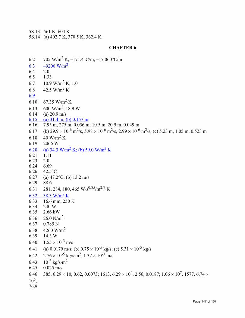
5S.13 561 K, 604 K 5S.14 (a) 402.7 K, 370.5 K, 362.4 K
CHAPTER 6
6.2 705 W/m2 K, –171.4°C/m, –17,060°C/m 6.3 –9200 W/m2
6.4 2.0 6.5 1.336.7 10.9 W/m2 K, 1.0 6.8 42.5 W/m2 K6.96.10 67.35 W/m2 K6.13 600 W/m2, 18.9 W6.14 (a) 20.9 m/s 6.15 (a) 31.4 m; (b) 0.157 m6.16 7.95 m, 275 m, 0.056 m; 10.5 m, 20.9 m, 0.049 m 6.17 (b) 29.9 10-6 m2/s, 5.98 10-6 m2/s, 2.99 10-6 m2/s; (c) 5.23 m, 1.05 m, 0.523 m6.18 40 W/m2 K6.19 2066 W 6.20 (a) 34.3 W/m2 K; (b) 59.0 W/m2 K6.21 1.11 6.23 2.0 6.24 6.69 6.26 42.5°C6.27 (a) 47.2 C; (b) 13.2 m/s 6.29 88.66.31 281, 284, 180, 465 W s0.85/m2.7 K6.32 38.3 W/m2 K6.33 16.6 mm, 250 K6.34 240 W 6.35 2.66 kW 6.36 26.0 N/m2
6.37 0.785 N6.38 4260 W/m2
6.39 14.3 W 6.40 1.55 10-3 m/s6.41 (a) 0.0179 m/s; (b) 0.75 10-5 kg/s; (c) 5.31 10-5 kg/s 6.42 2.76 10-5 kg/s m2, 1.37 10-3 m/s 6.43 10-6 kg/s m2
6.45 0.025 m/s 6.46 385, 6.29 10, 0.62, 0.0073; 1613, 6.29 104, 2.56, 0.0187; 1.06 107, 1577, 6.74 105,76.9
Page 147 of 167

6.47 (a) 120 W/m2 K; (d) 0.51 m/s 6.48 (a) 4.64 10-4 kg/s; (b) 1247 W 6.49 (a) 0.975 10-3 kmol/m3, 0.0258 atm; (b) 9.28 10-4 kg/s m2
6.50 (a) 1.63 10-4 kg/s; (b) 282.2 K6.51 1.50 10-3 kg 6.52 359 W/m2 K6.53 (a) 25.8 m/s; (b) 25.2 W/m2 K, 80.8 W/m2 K, 162 W/m2 K6.54 (a) 0.031, 0.80; (b) 198 W/m2 K; (c) 74% 6.55 2 10-3 kg/s m2
6.56 0.00395 m/s 6.57 (b) 9.92 W 6.58 7.78 km 6.59 (a) 7.25 10-6 kg/s; (b) 22.4 W, 2791 W/m2
6.60 (a) +795 W/m2, +131 W/m2, –563.1 W/m2; (c) 1227 W/m2
6.61 784 W 6.62 (a) 0.70 kg/h; (b) 85.6°C 6.63 21.8 W 6.64 2950 W 6.65 (a) 4.7°C; (b) 0.0238 m/s; (c) 16.2°C 6.66 (a) 0.0142 bar, 0.214; (b) 0.225; (c) 0.242 6.67 0.218 6.68 (a) 22.7 W/m2 K, 454 W; (b) 2.12 10-2 m/s, 3.32 kg/h; (c) 2685 W 6.69 (a) 0.172 m/s, 65.3 s; (b) 173 W/m2 K, 77,500 W/m2; (c) 429°C 6.70 (a) 6.71 10-3 m/s; (b) 8.97 W/m2 K6.71 (a) 0.0113 m/s; (b) 90 J 6.72 (b) –0.32 K/s
6S.2 40.83 C6S.3 (b) 1510 W/m, 453 kg/s2 m6S.4 (a) 34.2 N/m2, 0.738 N/m2; 6840 W/m2, 148 W/m2; (b) 1.37 106 W/m3, 2.95 104
W/m3;(c) 34.0°C, 30.5°C 6S.5 (a) 0.0028, 0.0056, 13.4; (b) 3.38 6S.7 (b) 117°C 6S.8 (a) 6.66 107 W/m3; (b) 1460 W; (c) 81.2°C, 303°C 6S.14 (e) 6.71 10-4 kg/s
CHAPTER 7
7.1 (a) 3.99 mm, 4.48 mm; 0.93 mm, 0.52 mm; 23.5 mm, 1.27 mm; 0.34 mm, 1.17 mm 7.2 (a) 0.147 m, 0.0143 m; (b) –1300 W/m2, 0.0842 N/m2; (c) 0.337 N/m, -5200 W/m 7.3 (a) 0.126 mm, 0.399 mm, 1.262 mm, 141 mm; (b) 6.07 N/m2, 1.92 N/m2, 0.61 N/m2,0.528 m/s, 0.167 m/s, 0.053 m/s
Page 148 of 167

7.47.8 (a) 8.71 105 W/m3; (b) 158.4°C 7.9 (a) 51.1 W, 12.2 W, 8.3 W, 255.3 W 7.10 13,600 W/m, 9780 W/m, 5530 W/m7.11 (a) 0.257 N, 8.13 W/m2 K, 1950 W; 0.227 N, 7.16 W/m2 K, 3440 W; (b) 0.620 N, 9050 W/m2 K, 5430 W; 0.700 N, 12,600 W/m2 K, 15,100 W 7.12 (c) 4110 W/m2 K, 4490 W/m2 K, 5070 W/m2 K7.13 3.2 105, 1.5 106
7.147.15 (a) 17.6 W; (b) 143.6 W 7.16 (a) 5830 W/m 7.17 29°C7.18 (a) 13.5 W, 47.6 C; (b) 13.9 W, 41.0 C7.19 (a) 14.3 W, 125.9 C7.20 (a) 33.8°C, 797 W; (b) 675 W; (c) 90.6 kW 7.21 1570 W7.22 (a) 8.7 W/m2 K, 14.5 W/m2 K, 11.1 W/m2 K7.23 (b) ±4% 7.24 6780 W, -0.26°C/s7.25 (b) 213°C 7.26 (b) 256°C; (c) 210°C 7.27 –0.99 K/s, –1.47 K/s, 1.91 m 7.28 (b) 0.47; (c) 0.477.29 46.2 C7.30 2.73 m/s7.31 (a) 23.4 W, 28.2 C; (b) 271 W, 72.6 C; 105 W, 200 C7.32 (a) 27°C; (b) 77°C 7.33 (a) 64°C; (c) 6.6 m/s 7.34 42.5°C 7.35 (a) 98.3°C, 17.1 W/m2 K; (b) 86.1°C 7.36 (a) , 2.61 W/m2 K; , 2.74 W/m2 K; (b) 4.22 W/m2 K, 5.41 W/m2 K7.37 (a) 55 W; (b) 39 W 7.38 0.30 W, 0.81 W 7.39 0.66 W, 0.60 W 7.40 (a) 30.8 W/m2 K, 56.7 W/m2 K; (b) 0.633, 0.555 7.41 (a) 71.1 W/m, 20.4 kW/m, 1640 W/m 7.42 3.24 N/m, 520 W/m7.43 (a) 603 K; (b) 200 s 7.44 (a) 562 K; (b) 155 s 7.45 70.4 W7.46 (a) 2.20 W; (b) 37.4 mm; (c) 89.6; (d) 435% 7.47 (a) 235 W/m2 K; (b) 0.87 W; (c) 1.02 W 7.48 (a) 1012°C, 1014°C 7.49 (b) 97 m/s 7.50 (b) 195 mA
Page 149 of 167

7.52 (a) 27.6°C; (b) 27.6°C 7.53 (a) 45.8°C; (b) 68.3°C 7.54 (a) 0.924 W7.55 (a) 1.41 W7.56 (a) $0.415/m d; (b) $0.363/m d7.57 (a) 3640 W/m 7.58 452.2 K 7.59 (b) 18.7 mm 7.61 (a) 0.20 m/s; (b) 2.80 104 W/m2, 52% 7.62 (a) 12.8 s 7.63 (b) 340°C; (c) 309°C 7.65 3.26 m/s 7.66 (a) 0.011 N; (b) 3.14 W 7.67 (a) 0.489 N, 510 W; (b) 0.452 10-3 N, 1.59 W7.68 10.3 W 7.69 (a) 67 s; (b) 48 s 7.70 (a) 18.8°C; (b) 672°C 7.71 (a) 2 m/s, (b) 1.11 mm, 1.25 10-3 m3
7.72 (a) 737°C; (b) 274 s; (c) 760 C, 230 s 7.73 2.1 m/s, 1.6 m 7.74 1.1 m/s, 10.3 m7.75 (a) 0.0011 s, 166.7 m/s; (b) 7.8 10-4 s 7.76 180 mm 7.77 (a) 0.3 m/s; (b) 1.86 mm 7.78 (a) 6.83 s; (b) 936 K 7.79 (b) 337°C 7.80 726 K, 735 K 7.81 (a) 92.2 W; (b) 1.76 108 W/m3, 1422 K; (c) 1789 K 7.82 (a) 20.4; (b) 45.8°C 7.83 234 W/m2 K, 0.0149 bar, 28.4 kW/m 7.84 58.5 kW, 5.9 10-3 bar 7.85 16, 684 N/m2
7.86 –532 kW/m 7.87 (a) 7670 W, 47.6°C; (b) 195 N/m2, 56 W 7.88 (a) 39°C; (b) 0.00993 bar, 6.26 kW 7.89 (a) 435 W/m2 K; (b) 321 K, 2453 W 7.91 (a) 363 K; (b) 355 kW, 0.163 kg/s 7.92 1.68 W 7.93 1.45 K/s 7.94 (c) 0.179 kg/s 7.96 11,600 W, 140 W 7.97 (a) 3.56 s, 17 μm7.98 (a) 470.5 W/m2 K; (b) 40.1 s7.99 5044 s 7.100 65.7 kW
Page 150 of 167

7.101 (a) 941 C, 333 W; (b) 1314 C7.102 (a) 10.5°C, 0.0134 kg/s 7.103 (a) 41.2°C, 0.0154 kg/s 7.104 (a) 0.0728 m/s; (b) 0.0028 kg/s 7.105 (a) 9.29 10-4 kg/s m, 2265 W/m 7.106 5.93 kW 7.107 (a) 0.0135 kg/s m7.108 3.57 W 7.109 (a) 4.48 10-3 kg/s m2; (b) 11,800 W/m2; (c) 9.95 10-4 kg/s m7.110 (a) 9.5 10-4 kg/s, 9.5 10-4 kg/s, 9.3 10-4 kg/s; (b) 334.7 K, 332.8 K, 327.1 K 7.112 (a) 0.123 kg/h, 44.9 W; (b) 52.3°C 7.113 (b) 2.12 10-4 kg/s m2
7.114 28.6 min 7.115 337 W/m, 483 W/m, 589 W/m 7.116 (b) 5.35 10-4 kg/s m; (c) 1.275 kW/m 7.117 2.73 106 kg/day 7.118 2775 W, -0.13°C/s 7.119 0.0016 kg/s m2
7.120 (a) 4.81 10-4 kg/s m2, 1268 W/m2
7.121 (a) 20.3 kg/h; (b) 102 days 7.122 (a) 4.76 10-2 m/s; (b) 3.80 10-2 m/s 7.123 (a) 2.31 10-4 kg/s m7.124 (a) 0.30 kg/h m, 110 W/m; (b) 52.3°C 7.126 (a) 485 W; (b) 3135 W 7.128 (a) 9424 W/m, 0.0036 kg/s m7.129 45.6°C, 0.21 7.130 (b) 1.82 10-7 kg/s, -8.9 K/s 7.131 159 s 7.132 3.60 10-8 kg/s 7.133 278 K 7.134 (a) 0.080 m/s; (b) 50 ms; (c) 1.01 10-10 kg/s7.135 35 body diameters/s7.136 9.06 10-8 kg/s 7.137 (a) 1.12 10-8 kg/s; (b) 2.3 K 7.138 (a) 1.83; (b) 28.0°C, 0.00129 7.139 0.0016 kg/s m2
CHAPTER 8
8.1 0.041 m/s, -0.86 10-5 bar/m 8.2 0.0215 bar8.3 (a) 0.289 bar, 1.42 kW; (b) 0.402 bar, 1.97 kW 8.4 (a) 53.8 bar, 146 W 8.6
Page 151 of 167

8.7 367 K 8.8 0.50 m/s, 20.0°C8.9 0.84 MPa, 0.46 MW, 0.46 C8.10 (c) 0.46 C8.11 (b) 44.2°C 8.15 (b) 60.8°C 8.16 (a) 471 W, 113.5°C, 60°C, 153.5°C; (b) 353 W, 90.2°C, 20°C, 150.2°C 8.17 (b) 362 K 8.18 88.21 (c) 6018 W 8.22 (a) 35°C, 16,000 W 8.23 (a) 28.4°C, 44.9°C; 73.3°C, 64.5°C;73.3°C, 65.1°C 8.24 90 kg/h, 1360 W 8.25 26.8 m8.26 1281 W, 15.4 m 8.27 12,680 W/m2, 121°C, 52.7°C 8.28 (b) 1266 s8.29 5, -2.54 C/s8.30 (a) 1.56 m, 28.3 days 8.31 13.7 m, 0.078 W 8.32 (a) 10.6 m 8.33 $0.411/m d8.34 (a) 8.87 m, (b) 52.6°C 8.35 (a) 81.7°C; (b) 9.1 10-4 bars, 0.19 W 8.36 (a) 63°C; (b) 66.1°C 8.37 (a) 29.9°C, -1212 W, 4.03 N/m2
8.38 99°C, 5 atm, 1.14 10-3 kg/s 8.39 0.11 m 8.40 0.39 m 8.41 7840 W/m2, 7040 W/m2
8.42 (a) 323 K; (b) 325 K 8.43 (a) 578°C 8.44 (a) 1384 K; (b) 5.2 10-2 kg/s, 890 K 8.45 (a) 198°C, 71 N/m2, 221 W; (b) 195°C, 119 N/m2, 415 W 8.46 (a) 85.6°C, 661 W 8.47 (a) 42.2°C, 7500 W, 1.29 h; (b) 0.324 h 8.49 (a) 100 kW; (b) 2.67 kW 8.50 343 W/m 8.51 80.3 W/m 8.52 (a) 543°C, 232°C 8.53 81.4°C 8.54 (a) 37.1°C; (b) 47.4°C 8.55 (a) 98.5 m; (b) 10.6 m 8.56 (a) 35.1°C; (b) 95.8°C; (c) 96.9°C 8.57 489 W/m 8.58 (a) 10 kW; (b) 3.4 m
Page 152 of 167

8.60 (a) 409 W/m2 K; (b) 93.4 W/m2 K; (c) 76.1 W/m2 K, 15°C 8.61 9.3 m 8.62 15.7°C, 438 W 8.63 (b) 111°C, 9.1 106 W 8.65 (a) 35°C; (b) 5.6; (d) 732 W/m2 K; (e) –66.7 W; (f) 0.81 m 8.66 (b) 244 W/m, 187°C 8.67 0.90, 308.3 K 8.68 (b) 53°C 8.69 85°C, 53 mm 8.73 33.2°C 8.74 379 K, 406 K 8.75 88°C 8.76 (a) 0.485 W; (b) 0.753 W; (c) 0.205 Pa, 1.02 Pa8.77 (a) 53,700 W/m2; (b) 123,400 W/m2
8.78 2720 W, 312 K 8.79 (a) 2600 W/m 8.80 (a) 1.9 m 8.81 9330 W/m2 K, 1960 W/m2 K8.82 (b) 305.3 K, 15.7 kW 8.84 30°C, 156 N/m2
8.85 (a) 3.35 kW; (b) 69 s 8.86 59.7°C, 20°C, 75.7°C; 27.9°C, 20°C, 37.5°C 8.87 510 W/m2
8.89 116.5°C, 5 atm, 1.38 10-3 kg/s 8.90 2.51 m, 388°C 8.91 (a) 704.5 K; (b) 683 K, 1087 K, 300 K 8.92 (a) ~25.1°C 8.93 19.7 m, 1575 W/m2
8.94 58.4 m 8.95 (a) 20.6°C, 0.085 W; (b) 18.9°C, 0.128 W; (c) 21.5°C 8.96 (a) 9.77 m; (b) 159 mm; (c) 775 N/m2, 379 N/m2; (d) 2.25 10-3 kg/s8.97 6.90 10-2 kg/s, 5.79 m, 67.8 mm8.98 (a) 35.1 C; (b) 33.2 C8.99 (a) 3190 W, -2039 W; (b) 9197 W, -8065 W8.100 (a) 81.3 C8.101 310 K, 418 W 8.102 (a) 307.8 K, 373 W; (b) 704 W 8.103 (a) 298.6 K, 45 W; (b) 349.9 K, 3.0 W 8.104 (a) 0.48°C; (b) 43.6°C, 27.6°C 8.105 (a) 52 mm; (b) 316 K; (c) 15.9 106 Pa; (d) 1.63 km, 1650 s8.106 (b) 2.60 10-5 kg/s, 307.7 K8.107 2.42 10-2 m/s 8.108 0.0032 m/s 8.109 0.024 m/s
Page 153 of 167

8.110 3.89 10-2 m/s, 107 W/m2 K; 1.12 10-2 m/s, 31 W/m2 K8.111 (a) 50.6 W; (b) 34.2°C 8.113 0.017 kg/m3, 4.33 10-6 kg/s 8.114 2.1 m 8.115 (a) 3.64 m; (b) 46.7 W 8.116 (a) 8.7 mm Hg, 0.0326 kg/m3; (b) 3.2 10-5 kg/s 8.117 (a) 0.0050 m/s; (b) 0.134 liter/day 8.118 (d) 0.0181 kg/m3
CHAPTER 9
9.1 300.9 10-6 K-1
9.2 727, 12.5, 512, 1.01 106
9.3 5.8, 663, 209 9.4 5.20, 23.78, 108.79.5 0.8819.6 (a) 17.5 mm; (b) 0.47 m/s, 3.5 mm; (c) 4.3 W/m2 K; (d) 0.60 m 9.7 12.6 mm 9.8 4.42 W/m2 K, 4.51 W/m2 K9.9 (a) 34 mm; (b) 16.8 W 9.10 (a) 3.03 W/m2 K; (b) 2.94 W/m2 K9.12 (b) 1154 s 9.13 11.7 W 9.14 (b) –0.099 K/s 9.15 6.5 W/m2 K9.169.17 153 W 9.18 (b) 223 W, $0.43/day 9.19 273.8 K, 174.8 W 9.20 274.4 K, 273.2 K, 168.8 W 9.21 (a) 4010 W; (b) 2365 s 9.22 (a) 347 W/m2 K9.23 (a) 364.2 W; (b) 46.5 C, 16.4%9.24 –0.136 K/s 9.25 (a) 118 kW/m3
9.26 24.8 W/m2
9.27 74°C, 68°C 9.28 (a) 35.8°C; (b) 28.8°C; (c) 68.8°C, 49.5°C 9.29 (a) 94.3 W 9.30 (a) 74.9°C, 1225 W; (b) 71.4°C, 1262 W 9.31 (a) 2.13 106 W, 92% 9.33 (a) 72.7 W; (b) 483 W 9.34 86.5 W/m9.35 (a) 19.3°C, 19.3°C, 20.1°C; 21.6 W/m, 27.0 W/m, 26.2 W/m 9.36 468 W
Page 154 of 167

9.37 (a) 238 W/m 9.38 0.560 W/m K, 0.815 9.39 (a) 7.46 W/m2 K; (b) 8.49 W/m2 K, 264 K 9.40 90.2 W9.41 56.7 C, 4.30 K/W, 3.56 K/W, 0.30 K/W, 4.2 10-3 K/W 9.42 45.3°C, 1007 W 9.43 (a) 2.91 105 W; (b) 8.53 104 W, 1463 K; (c) 0.13 m 9.45 (a) 250 W; (b) 181 s 9.46 (a) 42.9 min; (b) 11.0 min 9.47 (a) 4.0 W/m2 K; (b) 3.2 W/m2 K; (d) 45.7°C, 34.0°C 9.48 (a) 18.9 W; (b) 174°C 9.49 (a) 3.71 W/m2 K, 44.5 W/m; (b) 4.50 W/m2 K, 54.0 W; (c) 4.19 W/m2 K, 50.3 W/m 9.50 (a) 92.7; (b) 85.2; (c) 83.2 9.51 21.6 kW 9.52 57°C 9.53 780 W/m 9.54 698 W/m 9.57 (a) 56.8°C; (b) 1335 W; (c) 7.27 h 9.58 (a) 929 W/m; (b) 2340 W/m; (c) 187 W/m 9.59 103 W/m 9.60 (a) 50.8 W/m, 0.953; (b) 56.9 W/m 9.61 79°C 9.62 64.8°C 9.63 (b) 8 W/m2 K, 30.2 W/m 9.64 (a) 2.04 W; (b) 1.97 W 9.65 $0.265/m d9.67 581°C, 183 s 9.69 (a) 207 W/m2 K; (b) 387 W/m2 K9.70 (b) ~1.1 h 9.71 (a) 9.84 W/m2 K; (b) 32.1 W/m2 K; (c) 221 s; (d) 245 s 9.72 (a) 163 W/m, 41.7°C; (b) 60.8°C, 12.5°C, 52.8 W/m 9.73 (a) 45.8 m, 7 9.74 (a) 33.3 kW; (b) ~855 s, 9.07 kg 9.75 (a) 13.6 W/m2 K, 4.7 W/m2 K, 70.2°C, 20.5; (b) 70.7 C, 18.1 9.77 (c) 0.17 m/s, 0.00185 m/s9.78 (a) 1.55 W; (b) 187 W; (c) 57.0 W 9.79 8.62 W 9.80 (a) 10.2 W/m2 K, 1210 W/m2 K9.82 7.12 mm, 63.1 W 9.83 91.8 W 9.84 (a) 7.2 W, $0.10 9.85 (a) 28.8 W 9.86 8.13 mm, 19, 380 W 9.87 (a) 18.0 W; (b) 19.6 mm 9.88 26.3 kW/m 9.89 7 mm
Page 155 of 167

9.90 61 W 9.91 84 W/m2
9.92 (a) 429 kg; (b) 105 106 J, 0.102; (c) 33.4 kg 9.93 (a) 124 W/m2; (b) 146 W/m2; (c) 26 W/m2
9.94 (a) 1.57 9.95 (a) 525 W/m2; (b) 4; (c) 101 W/m2
9.97 (a) 9.1°C, -9.6°C, 35.7 W 9.98 (a) 74%, 35.4°C 9.99 43.9 W, 28.3 W9.100 (a) 466 W 9.101 (a) 44.9 W/m; (b) 47.3 W/m 9.102 43.4 W/m 9.103 (a) 30.7 C; (b) 0.685 µm/s9.104 463 W/m 9.105 0.022 kg/s 9.106 1.339.108 2.0 m/s 9.109 (a) 54.6 W/m; (b) 72.3 W/m; (c) 70.7 W/m; (d) 235 W/m 9.111 7.2 kW, -0.28 C/s9.112 43.9 W, 47.9 W 9.113 6.21 10-5 kg/s m9.114 (a) 9.18 W; (b) 6.04 105; (c) 4.47 W/m2 K; (d) 0.00398 m/s, 1.44 kg/day, 40.2 W; (e) 59 W9.115 1253 MW, 246 MW, 1105 MW9.116 77 A, 102 A
CHAPTER 10
10.110.2 4640 W/m2, 8500 W/m2, 40,000 W/m2 K10.3 (c) 0.032 mm 10.4 (a) 38,600 W/m2 K; (b) 0.017 10.5 13,690 W/m2 K10.6 20.6 C10.7 73 kW/m2, 232 kW/m2; 105 kW/m2, 439 kW/m2
10.8 (b) 89°C 10.9 1.34 MW/m2, 0.512 MW/m2, 0.241 MW/m2, 1.26 MW/m2
10.10 8.55 kW, 14 kg/h, 0.384, 30°C 10.11 (a) 110°C, 1.043 106 W/m2; (b) 109°C 10.12 (a) 3.5 W, -19°C 10.13 559 W, 6.89 10-4 kg/s, 0.026 10.14 ~9, 119°C 10.15 152.6°C, 166.7°C 10.16 175 A 10.17 4.70 MW/m2, 23.8 MW/m2
Page 156 of 167

10.20 55.4 C10.21 0.81 MW/m2
10.23 (a) 73.8°C, 82°C; (b) 1.13 105 W/m2
10.24 (a) 0.0131; (b) 144.6°C, 182.1°C10.26 (a) 180 W/m2 K, 0.067; (b) 300 C10.27 835 W10.28 (a) 858 kW/m10.29 1.34 MW/m2, 2048 K10.30 (a) 907 W/m, 1.4 kg/h m; (b) 107.6 C, 1.4 kg/h m10.31 (b) 82%10.32 0.475 MW/m 10.33 (a) 146 kW/m2
10.34 4.16 104 W/m2
10.35 (a) 0.18 s; (b) 37.4 s 10.37 68.0 kW/m 10.38 (a) 197 C, 0,672; (b) 691 C10.39 (a) 35.6 C; (b) 54.0 C10.40 3.03 mm, 3.65 mm, 4.93 mm, 2.14 mm, 1.43 mm 10.41 1.11 10-3 kg/s 10.42 6.69 mm10.43 16.0 kW, 7.1 10-3 kg/s10.44 40.4 kW, 17.8 10-3 kg/s10.45 (a) 78°C 10.46 (a) 1.07 MW, 0.444 kg/s; (b) 0.98 MW, 0.407 kg/s 10.47 2.21 kW, 2.44 10-3 kg/s 10.48 (a) 649 kW/m; 0.272 kg/s m10.50 4.8 MW/m, 1.93 kg/s m10.51 (a) 48.6°C, 4270 W/m, 0.0018 kg/s m10.53 19.1 kW, 8.39 10-3 kg/s 10.54 4.28 10-3 kg/s m10.55 28.3 kW/m, 1.16 10-2 kg/s m10.56 (a) 144 mm 10.57 0.0080 kg/s, 0.0020 kg/s; 0.0086 kg/s, 0.0014 kg/s 10.58 (a) 459 kg/h m10.59 22,200 W/m2 K, 9050 W/m2 K10.60 (a) 0.0118 kg/s, 7.98 10-3 kg/s; (b) 50.6°C, 55.4°C; (c) 6.23 m 10.61 2.78 10-3 kg/s 10.62 2.0 s, 3.91 10-5 kg 10.63 7100 W/m2 K, 9.0 10-3 kg/s m10.64 144,900 W/m2 K, 7.56 10-4 kg/s 10.65 6.29 10-2 kg/s m10.66 0.023 kg/s, 0.0014 kg/s
Page 157 of 167

10.67 2.11 W, 0.0332 m2
10.68 (a) 114.0°C; (b) 80.9°C, 2.6 10-4 kg/s 10.69 (a) 79.4°C, 55.7 W; (b) 16.7 mm 10.70 (a) 0.286 kg/s, 0.089 kg/s; (b) 379.7 K, 1.27 bar10.72 (a) 1870 W, 325 K, 300 K
CHAPTER 11
11.2 (a) 92 W/m2 K; (b) 690 W/m2 K11.3 (a) 1.52; (b) 0.304; (c) 0.1011.4 249 W/m2 K, 1140 W/m2 K11.5 11,800 W/m 11.6 920 W/m 11.7 (a) 2255 W/m2 K; (b) 1800 W/m2 K; (c) 29.4°C 11.8 (a) 98 W/m2 K; (b) 512 W/m2 K11.9 168 W/m2 K11.10 29.5 W/m2 K11.11 12.6 W/m2 K11.13 3.09 m2, 2.64 m2, 2.83 m2, 2.84 m2
11.14 4.75 m2
11.15 5.64 10-4 m2 K/W11.16 (a) 0.97 m; (b) 2250 W, 145°C, 338 W/m2 K, 9.59 10-4 m2 K/W11.18 (a) 48°C; (c) 132 W/m2 K; (d) 0.8; (e) 1 11.20 (a) 7600 W, 48.1°C; (b) 40 m 11.21 0.0029 m2 K/W11.22 5.19 kg/s, 37.5 m 11.23 (a) 1.58 m2
11.24 (a) 357 K, 515 K; (b) 30.7 W/m2 K11.25 (a) 785 W/K, 5.0 m; (b) 18.4°C 11.26 (a) 13 m2, 679 kW, 37.5°C; (b) $178,000/yr 11.27 (a) 74%; (b) 24°C 11.28 76.4°C 11.29 (a) 8.9 mm, 3.4 m 11.30 79.8°C, 8.70 10-4 kg/s 11.31 (a) 399 K, 70 11.32 33.1 m2
11.33 (a) 130 m; (b) 1985 W/m2 K; (d) 5.8%11.34 (a) 3930 W; (b) 3.74 liter/min; (c) 0.24 m2
11.35 (a) 3550 W/m2 K, 41.1°C, 0.85 kg/s 11.36 (a) 344.4 K 11.37 (a) 1.89 kg/s 11.38 (a) 720, 0.858 m; (b) 0.513 m
Page 158 of 167

11.39 (a) 41.9 m2, 20.7 kg/s; (b) 0.936 kg/s 11.40 (b) 0.50 11.41 36.8 C, 37.5 C11.42 50°C, 61.7°C 11.43 (a) 3.07 m2, 33.4°C 11.44 (a) 9.6 m 11.45 (a) 508 W/m2 K; (b) 1.95 m 11.46 (a) 55.7°C, 41.9°C; (b) 2300 W/m2 K; (d) 74.4°C, 0.55 11.47 (a) 11,200 m2; (b) 1994 kg/s 11.48 2.83 kg/s 11.49 (a) 206; (b) 26.1°C; (c) 17.4 kg/s 11.50 (a) 686 W, 11.0 C; (b) 10,087 W, 24.5 C; (c) $1765 11.51 (a) 129.7°C 11.52 808 W/m2 K11.53 (a) 61 W/m2 K; (b) 0.64; (c) 46.2°C 11.54 68, 7.1 m 11.55 (a) 71 m2
11.56 (a) 0.53 105 W, 0.47 11.57 34.1°C 11.58 36.6°C, 143.5°C 11.59 241 m2
11.60 (a) 29.4% 11.61 1014 K, 800 K, 514 K, 0.70 11.62 (a) 204 kW, 57.3 C, 42.7 C; (b) 2.33 m 11.63 (a) 44.6 kW; (b) 0.65; (c) 0.55 11.64 (a) 8280 W; (b) 98.4°C, 87.2°C; (d) 5470 W, 0.66 11.66 (a) 0.0354 m or 0.261 m, 0.34 m11.67 41 m2
11.68 (a) 26.8°C 11.69 (a) 2 105 W, 19.6°C, 19.6°C 11.70 4.56 m 11.71 (a) 73.9 W/m2 K; (b) 496 K, 369 K 11.72 (a) 104°C 11.74 (a) 0.752 m2; (b) 0.576 m2, 0.0855 kg/s; (c) 0.723 m2, 317 K 11.75 (a) 0.672 kW; (b) 8°C, 61°C, 1.43 kW 11.76 (a) 335 K; (b) 8.11 m; (c) 0.666 11.77 (a) 30.3%; (b) 27.5 kg/s 11.78 (a) 86.5 kW/K 11.79 66.3 W/m2 K11.80 0.082 m3, ~13, ~11, 0.54 m 11.81 56.2 W/m2 K, 0.026 m3
11.82 3 11.83 285 K 11.84 ~11
Page 159 of 167

11.85 564 K
11S.1 160 W/m2 K11S.2 29.6 W/m2 K11S.3 4.75 m2
11S.4 5.74 10-4 m2 K/W11S.5 (a) 1.5 m2
11S.6 33.1 m2
11S.7 9.6 m11S.8 (a) 11,100 m2; (b) 1994 kg/s11S.9 878 W/m2 K11S.10 243 m2
11S.11 4.8 m
CHAPTER 12
12.1 12.1 W/m2, 28.0 W/m2, 19.8 W/m2
12.2 (a) 1.38 10-3 W; (b) 2.76 W/m2
12.3 8 10-6 J 12.4 (a) 193 mm; (b) 940 W/m2
12.5 (a) 60 mW; (b) 95.5 W/m2 sr; (c) 47.8 μW 12.6 1086 W/m2
12.7 (a) 1446 W/m2
12.8 167.6 W/m2
12.9 0.2512.10 (a) 2000 W/m2; (b) 637 W/m2 sr; (c) 0.50 12.11 (a) 0.10 W; (b) 1273 W/m2 sr; (d) 0.10 W; (e) 3.6 10-7 W, 90 mW/m2; (f) 5.09 10-7
W,127 mW/m2; (g) 63.7 mW/m2
12.13 (a) 0.393 m 12.14 (a) 0.32 W/m2
12.15 789 K, 22 W; 273 K, 0.031 W; 1606 K, 37.7 W; 1750 K, 2761 W; 485 K, 0.628 W12.16 (a) 133 W, 76 W, 232 W, 5.54 μm 12.17 7348 W/m2
12.18 498 K 12.19 279 K 12.20 (a) 6.3 107 W/m2; (b) 5774 K; (c) 0.50 μm; (d) 278 K 12.21 (a) 6.74 10-5 sr; (b) 2.0 107 W/m2 sr 12.22 (a) 0.50 μm, 1.16 μm, 1.93 μm, 9.50 μm, 48.3 μm; (b) 0.125, 0.366, 0.50912.23 (a) 0.226, 0.044; (b) 0.50 mm, 1.0 mm 12.24 (a) 0.0137, 0.376; 0.359, 0.132 12.25 (a) 9.84 kW/m2, (b) 6.24 kW/m2
Page 160 of 167

12.26 278.4 W 12.28 (b) 0.90 K, 7.1 K 12.29 (a) 0.352; (b) –1977 K/s 12.30 (a) 0.249; (b) 0.35812.32 (a) 0.25, 2.27 105 W/m2
12.33 (a) 66.2 W/m2; (b) 8.76 μm 12.34 0.636, 76.9 kW/m2
12.35 1.45 12.39 (c) 995.3 K 12.40 (a) 3.3%, 5.3%; (b) 10% 12.41 0.373, -5.78 K/s, 311 s 12.42 34.7 kW/m2
12.43 (b) 7500 W/m2; (c) 2250 W/m2; (d) 0.30 12.44 (a) 0.50, 0.60; (b) 3.62 105 W/m2, 5.44 105 W/m2; (c) 0.126 W/m2 μm; (d) 10.3 μm 12.45 (a) 0.383; (b) 0.958, 0.24012.46 515 W/m2, 1306 W/m2, 1991 W/m2, 3164 W 12.47 2.51 10-6 W 12.48 1480 μW 12.49 (a) 0.774; (b) 0.1 12.50 (a) 0.45; (b) 0.56; (c) -22,750 W/m2
12.51 (a) 0.311; (b) 74,750 W/m2; (c) -60,750 W/m2
12.52 348 K 12.53 (a) 0.669; (b) 0.745; (c) 111 kW/m2; (d) 176 kW/m2
12.54 (a) 1.76 10-4 W; (b) 0.384 10-4 W 12.55 (a) 0.00099; (b) 0.295; (c) 0.86112.56 (a) 0.839, 0.568; (b) 0.329, 0.217 12.57 (b) 8.88 W, 78.2 W 12.59 (b) 0.599, 0.086, 0.315; (c) 1; (d) –615 W/m2
12.60 0.85, 0.85, 3.9 106 W/m2, 4.6 106 W/m2, 4.6 106 W/m2; 0.297, 0.106, 137 W/m2,4.6 106 W/m2, 1.38 106 W/m2
12.62 (a) 0; (b) 0.5 12.63 (a) 0.574; (b) 0.145; (c) 0.681, 0.53912.64 0, 0.3, 0.7, 0.303, 606 W/m2, 952 W/m2 K12.65 (a) 0, 577.4 K; (b) 0.89, 0.10; (c) 5600 W/m2, 630 W/m2; (d) 0.89, 0.10 12.66 0.34, 0.80, 1700 W/m2, -700 W/m2
12.67 (a) 0.60; (b) 200 W/m2; (c) -1200 W/m2
12.68 (b) 1.42 105 W/m2
12.69 (a) 0.720; (b) 0.756; (c) -11.8 kW/m2
12.70 (a) 0.225, 0.388, 0.5; (b) 443 kW/m2
12.71 7000 W/m2, 0.94 12.72 29.2 W, 344 K 12.73 (a) 0.748; (b) 29.6°C; (c) 402 W/m2
Page 161 of 167

12.74 (a) 117°C 12.75 (a) 22.2°C 12.76 (a) 25°C 12.77 (a) 19.8 W; (b) 538.2 K; (c) 855 s 12.78 (a) 145 W/m2; (b) 9.23 μW; (c) 8.10 μW 12.79 999 K 12.80 8.08 10-8 W 12.81 (a) 1.15 μW; (b) 1.47 μW 12.82 3.38 10-7 W 12.83 571 m/s, -15.5 m/s, 146 m, 0.256 s12.84 (a) 134 K 12.85 (a) 1718 μV; (c) 1382 μV, 878 μV, 373 μV 12.86 (a) 23 C; (b) 44.6 C12.88 (a) 5441 W/m2
12.89 (a) 0.49; (b) 0.20; (c) 24.5 W 12.90 (a) 0.375; (b) 0.702; (c) 0.375 12.91 (b) 20 K/s 12.92 (a) 2.93 W/m K12.93 (a) 1425 K, 1.87 105 W/m2; (b) 5.95 10-5 W 12.94 (a) 314 μW; (b) 871 K 12.95 796 K, 793 K 12.96 (a) 0.643; (b) 0.200; (c) 1646 kW/m2; (e) 119 s12.97 (a) 839 K; (b) 770 K; (c) 850 K 12.98 32.5 s 12.99 (a) 1.83 s; (b) 54.3 W 12.100 (a) 1.56 109 W/m3; (b) 15.6 W/mm2, 7.8 W/mm2; (c) 772 s 12.101 (a) 126 W/m2 K12.102 (a) 0.799, 0.536; (b) 11.7 K/s; (c) 0.536; (d) 82 s 12.103 (a) 763 W; (b) 930 K; (c) 537 s 12.104 (a) 0.80, 0.713; (b) 233 kW/m2, 9.75 K/s; (d) 186 s; (e) 413 s; (f) 899 s 12.105 (a) 0.51 μm, 8.33 μm; (c) 0.30, 0.59, 0.68; (d) 0.66, 0.68; (e) 73.5 kW/m2
12.106 (a) 48.5°C 12.107 139°C, 3.47 W 12.109 329.2 K 12.110 (a) 0.8, 0.625; (b) 352 K 12.111 (a) 0.634; (b) 0.25; (c) 460 W/m2
12.115 (b) 35.5°C 12.116 (a) 8.16 105 W/m2
12.117 0.129 m, 39.1% 12.118 (a) 1.60 107 W, 75.8% 12.119 (b) 295.2 K; (c) 704 W 12.121 (a) 0.704; (b) 0.20; (c) 6.07 W/m2 K12.122 (a) 55.2°C; (b) 35.9°C 12.123 (a) 4.887 W; (c) 43.5 C
Page 162 of 167

12.124 96.5 W/m2
12.125 (a) 77.6°C; (b) –35.3°C 12.126 379 K, 656 K12.127 (a) 197 K; (b) 340 K 12.128 439 K 12.129 0.95 12.130 (a) 837 W, 1026 W 12.131 (a) 30.5°C, 2766 W; (b) –7.6°C, 4660 W; (c) 80°C, 9557 W 12.132 (a) 1.286; (b) 352 K, 145 K 12.133 714 W/m2
12.134 (a) 308 K, 278 K; (b) 211 K, 178 K12.135 (b) ~5.5 106 s 12.136 (a) 0 or , 294 K; (b) 13.57 μm, 205 K, 310.4 K12.137 (a) 57.9°C, 180 W; (b) 71.7°C; (c) –30.4°C 12.138 4.7°C, 16.2°C 12.140 (a) 43.1°C; (b) 29.2°C 12.141 25°C, 3.1 10-4 kg/s 12.142 (a) 0.0436 kg/m3, 0.0144 kg/m3, 6.76 10-6 kg/s, 21.2 W; (b) 503 W/m2, 3105 W/m2,627W/m2
CHAPTER 13
13.1 (a) 1.0, 0.424; (b) 0.50, 0.25; (c) 0.637, 0.363; (d) 0.50, 0.707; (e) 0.5, 0; (f) 1.0, 0.125; (g) 0.50, 0.637 13.2 (c) ~0.62 13.4 (b) 0.0767, 0.553; 0.0343, 0.80013.6 (a) 0.781; (b) 0.110 13.9 (a) 0.09 13.10 (b) 0.01 13.11 (a) 0.038; (b) 0.23 13.12 0.41 13.13 0.16313.15 27.7 μW/m2
13.16 (a) 354 mW/m2; (b) 1695 mW/m2
13.17 36,900 W 13.18 0.0492 kg/s m13.19 (a) 0.64; (b) 1700 W 13.20 1.69 105 W/m 13.21 456 K 13.22 (a) 13.4 W, 6825 W/m2
13.23 (a) 579.4 K; (b) 583 K 13.24 (a) 413 K; (b) 1312 W 13.25 544 K, 828 K 13.26 (a) 255 W; (b) 970 K, 837.5 K
Page 163 of 167

13.28 1.58 104 W/m2
13.29 0.162 W 13.30 11.87 kW 13.31 (c) 17 kW/m2; (d) 635 μW 13.32 63.8 W/m2
13.33 (a) 1.19 W; (b) 1.48 μW 13.34 (a) 69 mW; (b) 934.5 W/m2; (c) 1085 W/m2; (d) 1085 W/m2
13.35 (a) 507 K 13.36 (a) 308 K 13.37 774 K 13.38 (a) 48.8 K/s; (b) 15 s; (c) 14.6 s, 12.0 s, 6.8 s 13.39 1680 W/m, 2517 W/m, 916 K 13.40 (a) 109.7 W/m, 110.1 W/m; (b) 98.5 W/m, 103.8 W/m 13.41 (a) 14.2 kW/m2, (b) 56.7 kW/m2; (c) 14.2 kW/m2; (d) 42.5 kW/m2
13.42 (a) 1.58 W; (b) 0.986 13.43 46.2 kW/m2, 0.81413.44 (a) 0.963 13.46 (a) 30.13 W; (b) 30.65 W; (c) 31.41 W; (d) 55.8 W/kg, 79.2 W/kg, 75.1 W/kg 13.47 (a) 15.2 W/m 13.48 66.4°C, 71.4°C 13.49 30.2 W/m 13.50 69°C 13.51 (a) 45.6 kW/m2; (b) 2.1 kW/m2
13.52 1.14 10-4 kg/s 13.53 (a) 1995 W; (b) 191 W; (c) 983 W, 1.5% 13.54 548 K, 474 K 13.56 0.138 13.58 (a) 338 K; (b) 25.3 W/m2
13.59 90 mW 13.60 9 13.61 0.50 W/m, -49% 13.62 472°C 13.63 1225 K, 1167 K 13.64 (a) 896 K, 986 K; (b) 950 K, 990 K 13.65 (a) 288 W; (b) –1692 W; (c) 207 W; (d) –1133 W 13.66 423 K 13.67 10.1 kW/m 13.68 3295 W 13.69 (a) 12.6 W; (b) 0.873; (c) 590 K 13.70 (a) 169 kW/m; (b) 1320 K 13.71 (a) 1.83 13.72 (a) 8520 W/m; (b) 732 K 13.73 12.6 kW/m2
13.74 (a) 9870 W/m; (b) 853 K 13.75 (a) 25.3 kW; (b) 18.2 kW 13.76 (a) 1228 K; (b) 1117 K
Page 164 of 167
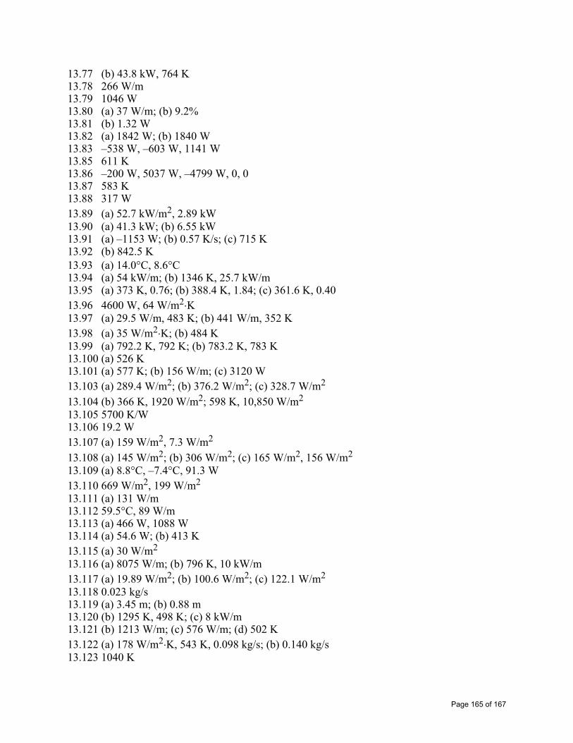
13.77 (b) 43.8 kW, 764 K 13.78 266 W/m 13.79 1046 W 13.80 (a) 37 W/m; (b) 9.2% 13.81 (b) 1.32 W 13.82 (a) 1842 W; (b) 1840 W 13.83 –538 W, –603 W, 1141 W 13.85 611 K 13.86 –200 W, 5037 W, –4799 W, 0, 0 13.87 583 K 13.88 317 W 13.89 (a) 52.7 kW/m2, 2.89 kW 13.90 (a) 41.3 kW; (b) 6.55 kW 13.91 (a) –1153 W; (b) 0.57 K/s; (c) 715 K 13.92 (b) 842.5 K13.93 (a) 14.0 C, 8.6 C13.94 (a) 54 kW/m; (b) 1346 K, 25.7 kW/m 13.95 (a) 373 K, 0.76; (b) 388.4 K, 1.84; (c) 361.6 K, 0.4013.96 4600 W, 64 W/m2 K13.97 (a) 29.5 W/m, 483 K; (b) 441 W/m, 352 K 13.98 (a) 35 W/m2 K; (b) 484 K 13.99 (a) 792.2 K, 792 K; (b) 783.2 K, 783 K 13.100 (a) 526 K 13.101 (a) 577 K; (b) 156 W/m; (c) 3120 W 13.103 (a) 289.4 W/m2; (b) 376.2 W/m2; (c) 328.7 W/m2
13.104 (b) 366 K, 1920 W/m2; 598 K, 10,850 W/m2
13.105 5700 K/W 13.106 19.2 W 13.107 (a) 159 W/m2, 7.3 W/m2
13.108 (a) 145 W/m2; (b) 306 W/m2; (c) 165 W/m2, 156 W/m2
13.109 (a) 8.8°C, –7.4°C, 91.3 W 13.110 669 W/m2, 199 W/m2
13.111 (a) 131 W/m 13.112 59.5°C, 89 W/m 13.113 (a) 466 W, 1088 W 13.114 (a) 54.6 W; (b) 413 K 13.115 (a) 30 W/m2
13.116 (a) 8075 W/m; (b) 796 K, 10 kW/m 13.117 (a) 19.89 W/m2; (b) 100.6 W/m2; (c) 122.1 W/m2
13.118 0.023 kg/s 13.119 (a) 3.45 m; (b) 0.88 m 13.120 (b) 1295 K, 498 K; (c) 8 kW/m 13.121 (b) 1213 W/m; (c) 576 W/m; (d) 502 K 13.122 (a) 178 W/m2 K, 543 K, 0.098 kg/s; (b) 0.140 kg/s 13.123 1040 K
Page 165 of 167

13.124 (a) 0.0197; (b) 825 K, 108 kW 13.125 15.1 kW 13.126 21.9 kW/m 13.127 98 kW/m 13.128 135 kW/m2
13.129 380 K, 89.6 kW/m2
13.130 0.515 kg/s 13.131 0.004 kg/s, 4.5 m/s, 367 K 13.132 (a) 530 K; (b) 0.00613 m/s 13.133 (a) 0.00341 kg/s m; (b) 889 K, 811 K
CHAPTER 14
14.1 0.233, 0.767 14.2 0.04 kmol/m3, 1.78 kg/m3, 0.5, 0.61; 0.04 kmol/m3, 1.13 kg/m3, 0.5, 0.39 14.3 0.0837, 0.1219 kg/m3, 0.0406 kmol/m3, 35.8 kg/kmol, 0.0146 kg14.4 (b) 0.31, 0.27, 0.42; 0.35, 0.40, 0.25 14.6 0.36 10-4 m2/s, 0.52 10-4 m2/s14.8 3.14 10-15 kmol/s14.10 (a) 1.087 10-8 kmol/s; (b) 1.107 10-8 kmol/s 14.13 0.257 kg/m2 h14.17 (a) 14.7 10-12 kg/s; (b) -3.5 10-7 bar/s 14.18 1.5 10-8 kmol/m2 s14.19 (a) 0.0189, 0.0120, 1, 1; (b) 0.205, 0.226, 5.53 10-6, 9.83 10-6
14.20 (a) 1.31 10-9 kmol/m2 s; (b) 0.0807 kmol/m3, 0.0404 kmol/m3
14.21 4.05 10-9 kg/s 14.22 1.9 10-22 kg/s m14.23 4 10-15 kg/s 14.24 1.39 10-6 kmol/s m14.25 (a) 1.91 10-3 kmol/m3 bar; (b) 0.32 10-16 kmol/s; (c) 0.32 10-16 kmol/s; (d) 014.26 0.003414.27 0.022 kg/h14.28 (a) 0.10; (b) 5.61 10-5 kg/s 14.29 6.66 10-9 kmol/s 14.31 0.0008, 7.48 10-8 kmol/s m2, 2.24 10-7 kmol/s m2
14.33 (b) 0.02 kmol/m3; (d) 9.60 10-5 kmol/m2 s14.34 (c) 3 10-5 kmol/m3
14.35 (c) 5.11 10-6 kmol/m3, 2.18 10-15 kmol/s14.37 (b) 5.38 10-11 kmol/s m2
14.38 (b) 9.08 10-7 kmol/m3
14.39 333 s 14.40 0.02 s
Page 166 of 167

14.41 8.42 h 14.42 (b) 0.0314 14.43 (a) 2071 days; (b) 198.3 kg/m3; (c) 198.3 kg/m3
14.44 (b) 1.85 kmol/m3
14.46 (a) 32 kg/m3; (c) 42.9 h 14.47 (a) 32 kg/m3; (c) 42.9 h; (d) 218 h 14.48 3.3 10-3 kmol/m3 bar, 8.5 10-13 m2/s14.49 3940 s14.51 (a) 0.0778 kmol/m3, 1.24 10-4; (b) 0.0117 kmol/m3, 1.9 10-5; 0.0346 kmol/m3, 5.5 10-5
14.53 (a) 2.5 μm; (b) 1.7 h; (c) 3.9 h
Page 167 of 167