Embed Size (px)
Citation preview

EMMY-W1 series Host-based multiradio modules with Wi-Fi and
Bluetooth
Data sheet
Abstract
This technical data sheet describes the EMMY-W1 series modules with Wi-Fi 802.11ac and
Bluetooth® v4.2 designed for both simultaneous and independent operation. These modules
include an integrated MAC/baseband processor and RF front-end components and can connect to
a host processor through SDIO 3.0 or high-speed UART interfaces. A PCM interface is available for
Bluetooth audio applications. These modules are offered in both professional and automotive
grades.
www.u-blox.com
UBX-15011785 - R11

EMMY-W1 series - Data sheet
UBX-15011785 - R11 Page 2 of 51
Document information Title EMMY-W1 series
Subtitle Host-based multiradio modules with Wi-Fi and Bluetooth
Document type Data sheet
Document number UBX-15011785
Revision and date R11 27-Aug-2019
Disclosure restriction
Product status Corresponding content status
Functional sample Draft For functional testing. Revised and supplementary data will be published later.
In development /
Prototype
Objective
specification
Target values. Revised and supplementary data will be published later.
Engineering sample Advance
information
Data based on early testing. Revised and supplementary data will be published
later.
Initial production Early production
information
Data from product verification. Revised and supplementary data may be
published later.
Mass production /
End of life
Production
information
Final product specification.
This document applies to the following products:
Product name Type number Firmware versions PCN reference Product status
EMMY-W161 EMMY-W161-00B-00 Wi-Fi:
15.44.7; 15.68.7;
BT:
15.26.7;15.28.7;15.29.7;
15.100.7
UBX-17005747
UBX-19030134
Mass production
EMMY-W161-A EMMY-W161-00A-00 UBX-17005747
UBX-19030134
Mass production
EMMY-W163 EMMY-W163-00B-00 UBX-16017374
UBX-17005747
Mass production
EMMY-W163-A EMMY-W163-00A-00 UBX-16017374
UBX-17005747
Mass production
EMMY-W165 EMMY-W165-00B-00 UBX-17005747 Mass production
EMMY-W165-A EMMY-W165-00A-00 UBX-17005747 Mass production
u-blox or third parties may hold intellectual property rights in the products, names, logos and designs included in this
document. Copying, reproduction, modification or disclosure to third parties of this document or any part thereof is only
permitted with the express written permission of u-blox.
The information contained herein is provided “as is” and u-blox assumes no liability for its use. No warranty, either express or
implied, is given, including but not limited to, with respect to the accuracy, correctness, reliability and fitness for a particular
purpose of the information. This document may be revised by u-blox at any time without notice. For the most recent
documents, visit www.u-blox.com.
Copyright © u-blox AG.

EMMY-W1 series - Data sheet
UBX-15011785 - R11 Page 3 of 51
Contents Document information ................................................................................................................................ 2
Contents .......................................................................................................................................................... 3
1 Functional description ......................................................................................................................... 5
1.1 Overview ........................................................................................................................................................ 5
1.2 Applications ................................................................................................................................................. 5
1.3 Product features ......................................................................................................................................... 6
1.4 Block diagrams ............................................................................................................................................ 7
1.5 Product description .................................................................................................................................... 8
1.6 Supported features .................................................................................................................................... 8
1.6.1 Wi-Fi features ...................................................................................................................................... 8
1.6.2 Bluetooth features ............................................................................................................................. 8
1.6.3 General product features .................................................................................................................. 8
1.6.4 Compliance ........................................................................................................................................... 9
1.7 Additional reserved MAC addresses ....................................................................................................... 9
2 Interfaces ............................................................................................................................................... 10
2.1 Operation mode configuration ...............................................................................................................10
2.2 SDIO interface ............................................................................................................................................10
2.2.1 Default speed and High speed modes ..........................................................................................10
2.2.2 SDR12, SDR25, SDR50 Modes (up to 100 MHz) (1.8 V) ...........................................................11
2.2.3 SDR104 Mode (150 MHz) (1.8 V) ..................................................................................................12
2.2.4 DDR50 Mode (50 MHz) (1.8 V) .......................................................................................................13
2.3 High Speed UART interface ....................................................................................................................14
2.4 PCM interface ............................................................................................................................................15
2.4.1 PCM interface specifications .........................................................................................................15
2.5 GPIO interface ............................................................................................................................................16
2.6 JTAG interface ..........................................................................................................................................17
3 Pin definition ......................................................................................................................................... 18
3.1 Pin description ...........................................................................................................................................18
3.2 Reset configuration ..................................................................................................................................20
3.3 Configuration pins ....................................................................................................................................20
4 Electrical specification ...................................................................................................................... 21
4.1 Absolute maximum ratings ....................................................................................................................21
4.2 Operating conditions ................................................................................................................................21
4.3 Digital pin ratings ......................................................................................................................................22
4.4 Wi-Fi power consumption .......................................................................................................................22
4.5 Bluetooth power consumption ...............................................................................................................23
4.6 Radio specifications .................................................................................................................................24
4.6.1 Wi-Fi ....................................................................................................................................................24
4.6.2 Bluetooth ............................................................................................................................................26
4.6.3 LTE co-existence ..............................................................................................................................26
5 Host drivers and firmware ................................................................................................................ 27
5.1 General principle ........................................................................................................................................27

EMMY-W1 series - Data sheet
UBX-15011785 - R11 Page 4 of 51
5.2 Supported operating systems ...............................................................................................................27
5.2.1 Linux ....................................................................................................................................................27
5.2.2 QNX ......................................................................................................................................................27
6 Mechanical specifications ............................................................................................................... 28
7 Qualification and approvals............................................................................................................. 30
7.1 Country Approvals ....................................................................................................................................30
7.1.1 European Union regulatory compliance .......................................................................................30
7.1.2 FCC compliance ................................................................................................................................31
7.1.3 IC compliance .....................................................................................................................................32
7.1.4 Australia and New Zealand regulatory compliance ...................................................................33
7.1.5 Korean KCC compliance ..................................................................................................................34
7.1.6 Japan radio equipment compliance..............................................................................................34
7.1.7 Taiwan NCC compliance ..................................................................................................................35
7.1.8 China SRRC Radio Transmission Equipment compliance .......................................................35
7.2 Approved antennas ..................................................................................................................................36
7.2.1 Wi-Fi / Bluetooth Dual Band Antennas .........................................................................................36
7.2.2 Bluetooth antenna ............................................................................................................................37
7.3 Bluetooth qualification .............................................................................................................................37
7.3.1 Bluetooth host stack ........................................................................................................................37
8 Product handling ................................................................................................................................. 38
8.1 Packaging ...................................................................................................................................................38
8.1.1 Reels ....................................................................................................................................................38
8.1.2 Tapes ...................................................................................................................................................38
8.2 Shipment, storage and handling ...........................................................................................................39
8.2.1 Moisture sensitivity levels ..............................................................................................................39
8.2.2 Mounting process and soldering recommendations ................................................................39
8.2.3 ESD handling precautions ..............................................................................................................40
9 Labeling and ordering information ............................................................................................... 42
9.1 Product labeling .........................................................................................................................................42
9.1.1 EMMY-W161 .....................................................................................................................................42
9.1.2 EMMY-W163 .....................................................................................................................................43
9.1.3 EMMY-W165 .....................................................................................................................................44
9.2 Explanation of codes ................................................................................................................................44
9.3 Ordering codes ...........................................................................................................................................45
Appendix ....................................................................................................................................................... 46
Related documents ................................................................................................................................... 48
Revision history .......................................................................................................................................... 49
Contact ........................................................................................................................................................... 51

EMMY-W1 series - Data sheet
UBX-15011785 - R11 Functional description Page 5 of 51
1 Functional description
1.1 Overview
The EMMY-W1 series provides a complete short range transceiver solution that can easily be
integrated into automotive and industrial applications. The modules are designed for both
simultaneous and independent operation of the following technologies:
IEEE 802.11a/b/g/n/ac data rates for Wi-Fi
Dual-mode Bluetooth v4.2
The EMMY-W1 series is a surface-mount device (SMD) component and can be used as a Wi-Fi
micro-access point supporting up to 10 clients. A coexistence feature at the chip level improves
parallel use of Bluetooth and Wi-Fi communication. For highest throughput and performance, a
module variant with separate Wi-Fi and Bluetooth antenna pins is also available.
The modules include an integrated MAC/baseband processor and RF front-end components and can
connect to a host processor through SDIO 3.0 and high-speed UART interfaces. The EMMY-W1
series are offered in automotive and professional grades (see Ordering codes and Block diagrams).
The automotive grade variant includes an automotive-qualified (AEC-Q100) chipset. A host driver
for Linux 3.x is available free of charge. The modules are radio type approved1 for Europe (ETSI RED),
US (FCC CFR 47 part 15 unlicensed modular transmitter approval), Canada (IC RSS), Korea (KCC),
Japan (MIC), Taiwan (NCC), Australia / New Zealand (ACMA) and China (SRRC). Approvals for other
countries may be possible upon inquiry.
1.2 Applications
Automotive applications
High definition (HD) video streaming (headrest displays, rear-view camera) and in-car gaming
Rapid sync-n-go applications and fast content download to the vehicle
Hands-free equipment (Bluetooth)
Industrial applications
Manufacturing floor automation, wireless control terminals and point-to-point backhaul
Outdoor content distribution
Mobile video streaming
Robust wireless connectivity in a broad range of industrial applications
1 See section 7.1 for an overview of the specific module variants that are approved for each country

EMMY-W1 series - Data sheet
UBX-15011785 - R11 Functional description Page 6 of 51
1.3 Product features
Table 1: EMMY-W1 series main features summary

EMMY-W1 series - Data sheet
UBX-15011785 - R11 Functional description Page 7 of 51
1.4 Block diagrams
The block diagrams of the EMMY-W1 series are provided in this section.
Figure 1: EMMY-W161/EMMY-W165 block diagram - Single antenna variant
In EMMY-W161, the band pass filter (2.4 GHz BPF) is a BAW filter that enables co-existence
with LTE. For the EMMY-W165 variant, the band pass filter provides no co-existence protection
against a co-located LTE transmitter.
Figure 2: EMMY-W163 block diagram - Dual-antenna variant
MAC/BB/RADIO
2.4GHz WLAN TX
2.4GHz WLAN/BT RX
BT TX
WLAN &
BT ANT
5GHz WLAN TX/RX 5GHz BPF &
DIPLEXER
2.4GHz
BPF
EMMY-W161 / EMMY-W165
SDIO
37.4 MHz
Crystal
VIO1
UART VIO2
PCM VIO2
BT LTE
COEXVIO2
PDn
SP3T
3.3V VIO1 VIO2 GND
VIO2GPIOs
DC/DC3.3V1.8V
1.1V
MAC/BB/RADIO
2.4GHz WLAN TX
2.4GHz WLAN RX
BT RX/TX
WLAN
ANT
5GHz WLAN TX/RX 5GHz BPF &
DIPLEXER
2.4GHz
BPF
EMMY-W163
SDIO
37.4 MHz
Crystal
VIO1
UART VIO2
PCM VIO2
BT LTE
COEXVIO2
PDn
2.4GHz
BPF
SP3T
3.3V VIO1 VIO2 GND
BT
ANTVIO2GPIOs
DC/DC3.3V1.8V
1.1V

EMMY-W1 series - Data sheet
UBX-15011785 - R11 Functional description Page 8 of 51
In EMMY-W163, the bandpass filters (2.4 GHz BPF) are ceramic bandpass filters.
An LTE co-existence variant is not available in the dual-antenna configuration.
1.5 Product description
Model Description
EMMY-W161 Professional grade module with 1 combined antenna pin for Wi-Fi and Bluetooth and integrated LTE filter
EMMY-W163 Professional grade module with 2 separate antenna pins for Wi-Fi and Bluetooth (no LTE filter)
EMMY-W165 Professional grade module with 1 combined antenna pin for Wi-Fi and Bluetooth (no LTE filter)
EMMY-W161-A Automotive grade module with 1 combined antenna pin for Wi-Fi and Bluetooth and integrated LTE filter
EMMY-W163-A Automotive grade module with 2 separate antenna pins for Wi-Fi and Bluetooth (no LTE filter)
EMMY-W165-A Automotive grade module with 1 combined antenna pin for Wi-Fi and Bluetooth (no LTE filter)
The EMMY-W161 is recommended for applications that have co-located Wi-Fi, Bluetooth and
LTE antennas and require co-existence of these wireless technologies. This module provides a
dedicated BAW bandpass filter instead of the ceramic bandpass filter. This filter rejects the
adjacent LTE bands B40, B7, B41, and B38. The integrated BAW filter is available only for the
single-antenna configuration (EMMY-W161). The module pinout, operating conditions, and
electrical characteristics are identical for all product variants. Differences in the RF parameters
are explained in the Radio specifications section.
1.6 Supported features
1.6.1 Wi-Fi features
Wi-Fi standards: IEEE 802.11a/b/g/n/ac/d/e/h/i/k 2/r/v 2/w
Simultaneous client and access point operation (up to 10 clients supported)
Support of Wi-Fi direct mode
IEEE 802.11ac 1x1 antenna configuration
IEEE 802.11 PHY data rates up to 433 Mbit/s
64- and 128-bit AES hardware encryption engine
WAPI encryption is supported by hardware
SDIO 3.0 host interface for Wi-Fi
1.6.2 Bluetooth features
Bluetooth v4.2 with Bluetooth Low Energy and Classic Bluetooth v2.1+EDR over SDIO or
high-speed UART interface
PCM interface for audio
MWS/LTE coexistence serial transport interface for connecting an external and co-located
LTE device 3
1.6.3 General product features
Driver support for Linux and QNX
Low-power and sleep modes for Bluetooth and Wi-Fi core
Coexistence arbitration for Wi-Fi/Bluetooth/LE/LTE operation
Small footprint (19.8 mm x 13.8 mm), LGA package
Product variant with integrated LTE co-location filter available
Automotive qualification tests (climatic, mechanical, and operating life tests) according to
ISO 16750-4
2 Supported by hardware but not supported by firmware currently. 3 Available on request

EMMY-W1 series - Data sheet
UBX-15011785 - R11 Functional description Page 9 of 51
1.6.4 Compliance
RoHS compliant
Radio type approvals4 for Europe, USA, Canada, Korea, Japan, Taiwan, China, Australia, and
New Zealand
1.7 Additional reserved MAC addresses
The EMMY-W1 module series has four unique consecutive MAC addresses reserved for each
module, from which the first two addresses are already stored in the configuration during
production. The first address is used for the Bluetooth communication while the second address is
configured for Wi-Fi communication. The Data Matrix Code on the label includes the Bluetooth MAC
address (see section 9). The remaining two MAC addresses are not used in the manufacturing
configuration, but are reserved for usage with the module.
MAC address Assignment Last two bits of MAC address Example
Module1, address 1 Bluetooth 0b00 D4:CA:6E:44:00:04
Module1, address 2 Wi-Fi 0b01 D4:CA:6E:44:00:05
Module1, address 3 (free for use) 0b10 D4:CA:6E:44:00:06
Module1, address 4 (free for use) 0b11 D4:CA:6E:44:00:07
Module2, address 1 Bluetooth 0b00 D4:CA:6E:44:00:08
Module2, address 2 Wi-Fi 0b01 D4:CA:6E:44:00:09
Module2, address 3 (free for use) 0b10 D4:CA:6E:44:00:0A
Module2, address 4 (free for use) 0b11 D4:CA:6E:44:00:0B
Table 2: MAC address assignment
4 See section 7.1 for an overview of the specific module variants that are approved for each country

EMMY-W1 series - Data sheet
UBX-15011785 - R11 Interfaces Page 10 of 51
2 Interfaces
2.1 Operation mode configuration
EMMY-W1 series module uses the GPIO_3 and GPIO_2 pins as host interface configuration input to
set the desired operation mode following a reset. The definitions of these pins are changed to their
usual functions after reset. When you need to configure the pins for a certain module operation
mode, you need to provide a 100 kΩ pull down resistor to the ground. No external circuitry is required
to set a configuration pin to high logical level.
External reset is not needed for proper operation due to internal power-up reset logic though it can
be used by the host controller through the PDn pin (active low) in case of an abnormal module
behavior.
After the firmware download, GPIO_3 and GPIO_2 pins can be used for secondary functionality such
as PCM_MCLK for GPIO_3 or GPIO itself. But this depends on the firmware or driver version.
Depending on the firmware or driver used, you can use either one or both host interface operation
modes:
GPIO_3 GPIO_2 Wi-Fi Bluetooth Number of SDIO functions
0 0 SDIO UART 1 (Wi-Fi)
0 1 SDIO SDIO 3 (Wi-Fi, Bluetooth)
1 0 SDIO UART 1 (Wi-Fi)
1 1 SDIO SDIO 3 (Wi-Fi, Bluetooth) 5
Table 3: Module configuration
2.2 SDIO interface
EMMY-W1 series modules support an SDIO device interface that conforms to the industry standard
SDIO 3.0 Full-Speed specification (4-bit SDIO up to 150 MHz) and allows a host controller using the
SDIO bus protocol to access the Wi-Fi and Bluetooth functions. The interface supports 4-bit SDIO
transfer mode at the full clock range of 0 to 150 MHz.
2.2.1 Default speed and High speed modes
Figure 3: SDIO protocol timing diagram- Default speed mode (3.3 V)
5 Default configuration.

EMMY-W1 series - Data sheet
UBX-15011785 - R11 Interfaces Page 11 of 51
Figure 4: SDIO protocol timing diagram – High speed mode (3.3 V)
Symbol Parameter Condition Min. Typ Max. Units
fPP Clock frequency Normal 0 - 25 MHz
High speed 0 - 50 MHz
TWL Clock low time Normal 10 - - ns
High speed 7 - - ns
TWH Clock high time Normal 10 - - ns
High speed 7 - - ns
TISU Input setup time Normal 5 - - ns
High speed 6 - - ns
TIH Input hold time Normal 5 - - ns
High speed 2 - - ns
TODLY(max) Maximal Output delay time Normal - 14 ns
TODLY(min) Minimal Output delay time Normal - 0 ns
TODLY Output delay time CL ≤ 40
pF (1 card)
Normal - 14 ns
TOH Output hold time High speed 2.5 - - ns
Table 4: SDIO timing data – Default speed, High speed modes (3.3 V)
2.2.2 SDR12, SDR25, SDR50 Modes (up to 100 MHz) (1.8 V)
Figure 5: SDIO protocol timing diagram – SDR12, SDR25, SDR50 modes (up to 100 MHz) (1.8 V)
EMMY-W1 series - Data sheet
UBX-15011785 - R11 Interfaces Page 12 of 51
Symbol Parameter Condition Min. Typ Max. Units
fPP Clock frequency SDR12/25/50 25 - 100 MHz
TIS Input setup time SDR12/25/50 3 - - ns
TIH Input hold time SDR12/25/50 0.8 - - ns
TCLK Clock time SDR12/25/50 10 - 40 ns
TCR, TCF, Rise time, fall time
TCR, TCF < 2 ns (max) at 100 MHz
CCARD = 10 pF
SDR12/25/50 - 0.2*TCLK ns
TODLY Output delay time
CL ≤ 30 pF
SDR12/25/50 - 7.5 ns
TOH Output hold time
CL = 15 pF
SDR12/25/50 1.5 - - ns
Table 5: SDIO timing data – SDR12, SDR25, SDR50 modes (up to 100 MHz) (1.8 V)
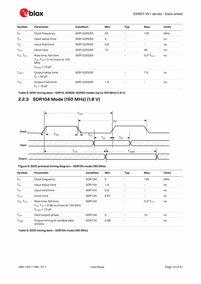
2.2.3 SDR104 Mode (150 MHz) (1.8 V)
Figure 6: SDIO protocol timing diagram – SDR104 mode (150 MHz)
Symbol Parameter Condition Min. Typ Max. Units
fPP Clock frequency SDR104 0 - 150 MHz
TIS Input setup time SDR104 1.4 - - ns
TIH Input hold time SDR104 0.8 - - ns
TCLK Clock time SDR104 6.67 - - ns
TCR, TCF, Rise time, fall time
TCR, TCF < 0.96 ns (max) at 150 MHz
CCARD = 10 pF
SDR104 - 0.2*TCLK ns
TOP Card output phase SDR104 0 - 10 ns
TODW Output timing of variable data
window
SDR104 2.88 - - ns
Table 6: SDIO timing data – SDR104 mode (150 MHz)

EMMY-W1 series - Data sheet
UBX-15011785 - R11 Interfaces Page 13 of 51
2.2.4 DDR50 Mode (50 MHz) (1.8 V)
Figure 7: SDIO CMD timing diagram – DDR50 mode (50 MHz)
Figure 8: SDIO DAT[3:0] timing diagram – DDR50 mode (50 MHz)

EMMY-W1 series - Data sheet
UBX-15011785 - R11 Interfaces Page 14 of 51
Symbol Parameter Condition Min. Typ Max. Units
Clock
TCLK Clock time
50 MHz (max) between rising edges
DDR50 20 ns
TCR, TCF, Rise time, fall time
TCR, TCF < 4.00 ns (max) at 50 MHz
CCARD = 10 pF
DDR50 0.2*TCLK ns
Clock Duty DDR50 45 55 %
CMD Input (referenced to clock rising edge)
TIS Input setup time
CCARD ≤ 10 pF (1 card)
DDR50 6 ns
TIH Input hold time
CCARD ≤ 10 pF (1 card)
DDR50 0.8 ns
CMD Output (referenced to clock rising edge)
TODLY Output delay time during data transfer mode CL ≤ 30 pF (1 card)
DDR50 13.7 ns
TOHLD Output hold time
CL ≥ 15 pF (1 card)
DDR50 1.5 ns
DAT[3:0] Input (referenced to clock rising and falling edges)
TIS2x Input setup time
CCARD ≤ 10 pF (1 card)
DDR50 3 ns
TIH2x Input hold time
CCARD ≤ 10 pF (1 card)
DDR50 0.8 ns
DAT[3:0] Output (referenced to clock rising and falling edges)
TODLY2x (max) Output delay time during data transfer mode CL ≤ 25 pF (1 card)
DDR50 7.0 ns
TODLY2x (min) Output hold time
CL ≥ 15 pF (1 card)
DDR50 1.5 ns
Table 7: SDIO timing data – DDR50 mode (50 MHz)
2.3 High Speed UART interface
The EMMY-W1 series modules support a high speed Universal Asynchronous Receiver/Transmitter
(UART) interface in compliance with the industry standard 16550 specification. The main features
of the UART interface are:
FIFO mode permanently selected for transmit and receive operations
2 pins for transmit and receive operations
2 flow control pins
Interrupt triggers for low-power, high throughput operation
High throughput (4 Mbps)
The UART interface operation includes:
Uploading the firmware to the module
Supporting data input/output operation for peripheral devices connected through a standard
UART interface

EMMY-W1 series - Data sheet
UBX-15011785 - R11 Interfaces Page 15 of 51
Baud Rate
1200 38400 460800 1500000 3000000
2400 57600 500000 1843200 3250000
4800 76800 921600 2000000 3692300
9600 115200 1000000 2100000 4000000
19200 230400 1382400 2764800
Table 8: Supported UART Baud rates
2.4 PCM interface
The EMMY-W1 series modules support a Pulse Code Modulation (PCM) interface that provides:
Master or slave mode
PCM bit width size of 8 bits or 16 bits
Up to 4 slots with configurable bit width and start positions
Short frame and long frame synchronization
2.4.1 PCM interface specifications
Figure 9: PCM timing specification – Master mode
Symbol Parameter Condition Min. Typ Max. Units
FBCLK - - - 2/2.048 - MHz
Duty Cycle BCLK - - 0.4 0.5 0.6 -
TBCLK rise/fall - - - 3 - Ns
TDO - - - - 15 ns
TDISU - - 20 - - ns
TDIHO - - 15 - - ns
TBF - - - - 15 ns
Table 9: PCM timing specification – Master mode

EMMY-W1 series - Data sheet
UBX-15011785 - R11 Interfaces Page 16 of 51
Figure 10: PCM timing specification – Slave mode
Symbol Parameter Condition Min. Typ Max. Units
FBCLK - - - 2/2.048 - MHz
Duty Cycle BCLK - - 0.4 0.5 0.6 -
TBCLK rise/fall - - - 3 - ns
TDO - - - - 30 ns
TDISU - - 15 - - ns
TDIHO - - 10 - - ns
TBFSU - - 15 - - ns
TBFHO - - 10 - - ns
Table 10: PCM timing specification – Slave mode
2.5 GPIO interface
The General-Purpose I/O (GPIO) interface is used to implement user defined input and output signals
to and from the 88W8887 chip such as external interrupts and other user-defined I/Os. Main
features of the GPIO interface include:
User-defined GPIO (each I/O configured to either input or output)
Each GPIO independently controlled
Each I/O configurable to output bit from GPIO_OUT
The general functions associated with each GPIO pin is shown in Table 11:
GPIO
Function
GPIO Pin
0 1 2 3 4 5 6 7 8 9 10 11 14 15 16 17
General
Input X X X X X X X X X X X X X X X X
Output X X X X X X X X X X X X X X X X
Interrupts
Input X X X X X X X X X X X X X X X X
Table 11: GPIO Functions – GPIO [17:14], [11:0]

EMMY-W1 series - Data sheet
UBX-15011785 - R11 Interfaces Page 17 of 51
GPIO_12 and GPIO_13 are not available.
2.6 JTAG interface
The Test interface pins are powered from the VIO2 voltage domain.
A
Figure 11: JTAG Timing Diagram
Symbol Parameter Condition Min. Typ Max. Units
TP_TCK TCK period - 40 - - ns
TH_TCK TCK high - 12 - - ns
TL_TCK TCK low - 12 - - ns
TSU_TDI TDI, TMS to TCK setup time - 10 - - ns
THD_TDI TDI, TMS to TCK hold time - 10 - - ns
TDLY_TDO TCK to TDO delay - 0 - 15 ns
Table 12: JTAG interface Timing Data

EMMY-W1 series - Data sheet
UBX-15011785 - R11 Pin definition Page 18 of 51
3 Pin definition
3.1 Pin description
Figure 12: EMMY-W1 series pin assignment (top view)
No Pin name Pin type Supply domain Description
1 GND Ground - Ground
2 NC - Reserved, do not connect
3 NC - Reserved, do not connect
4 NC - Reserved, do not connect
5 GPIO_0 I/O VIO2 BT2HOST_WAKEUP (Output)
6 GPIO_1 I/O VIO2 WL2HOST_WAKEUP (Output), Configuration pin (see section
3.3)
7 GPIO_14 I/O VIO2 HOST2WL_WAKEUP / JTAG_TCK test clock (Input)
8 GPIO_15 I/O VIO2 HOST2BT_WAKEUP / JTAG_TMS controller select (Input)
9 GPIO_16 I/O VIO2 UART_LTE_SIN / JTAG_TDI test data input (Input)
10 GPIO_17 I/O VIO2 UART_LTE_SOUT / JTAG_TDO test data output (Output)
11 GPIO_4 I/O VIO2 PCM_DIN (Input)
12 GPIO_5 I/O VIO2 PCM_DOUT (Output)
13 GPIO_6 I/O VIO2 PCM_CLK (Input if slave, Output if master)
2 31 4 5 6 7 8 9 10 11 12 13 14 15
2438
46
45
44
43
42
41
40
39
37 36 35 34 33 32 31 30 29 28 27 26 25
16
17
18
19
20
21
22
23
GND
GND
GND
GND
GND
GND
GN
D
NC
NC
NC
GP
IO_0
GP
IO_1
GP
IO_14
GP
IO_15
GP
IO_16
GP
IO_17
GP
IO_4
GP
IO_5
GP
IO_6
GP
IO_7
GN
D
GND
GND
SD_CLK
SD_CMD
SD_D0
SD_D1
SD_D2
SD_D3
GND
GND
GN
D
3V
3
VIO
1
VIO
2
PD
n
GP
IO_8
GP
IO_9
GP
IO_10
GP
IO_11
GP
IO_3
GP
IO_2
GN
D
NC
NC
GND
GND
ANT1
GND
GND
GND
GND
ANT2
GND
GND

EMMY-W1 series - Data sheet
UBX-15011785 - R11 Pin definition Page 19 of 51
No Pin name Pin type Supply domain Description
14 GPIO_7 I/O VIO2 PCM_SYNC (Input if slave, Output if master)
15 GND Ground - Ground
16 GND Ground - Ground
17 SD_CLK I VIO1 SDIO Clock input
18 SD_CMD I/O VIO1 SDIO Command line
19 SD_D0 I/O VIO1 SDIO Data line bit [0]
20 SD_D1 I/O VIO1 SDIO Data line bit [1]
21 SD_D2 I/O VIO1 SDIO Data line bit [2]
22 SD_D3 I/O VIO1 SDIO Data line bit [3]
23 GND Ground - Ground
24 GND Ground - Ground
25 3V3 Power 3.3V 3.3V Power supply (2.97 V - 3.63 V)
26 VIO1 Power VIO1 VIO1 Power supply (1.62V - 1.98 V, 2.97 V - 3.63 V)
27 VIO2 Power VIO2 VIO2 Power supply (1.62V - 1.98 V, 2.97 V - 3.63 V)
28 PDn Input - Full power down(active low)6
29 GPIO_8 I/O VIO2 UART_SOUT (Output), Configuration pin (se section 3.3)
30 GPIO_9 I/O VIO2 UART_SIN (Input)
31 GPIO_10 I/O VIO2 UART_CTSn (Input)
32 GPIO_11 I/O VIO2 UART_RTSn (Output)
33 GPIO_3 I/O 3.3V Configuration pin(see section 3.3), PCM_MCLK (output if master, input
if slave)
34 GPIO_2 I/O 3.3V Configuration pin (see section 3.3)
35 GND Ground - Ground
36 NC - Reserved, do not connect
37 NC - Reserved, do not connect
38 GND Ground - Ground
39 GND Ground - Ground
40 ANT2 I/O, RF - Bluetooth antenna only in case of EMMY-W163 module. Not connected
in case of EMMY-W161 or EMMY-W165 module7
41 GND Ground - Ground
42 GND Ground - Ground
43 GND Ground - Ground
44 GND Ground - Ground
45 ANT1 I/O, RF - Wi-Fi + Bluetooth antenna in case of single-antenna module. Wi-Fi
antenna only in case of dual-antenna module7
46 GND Ground - Ground
- Exposed pin Ground - Six Ground/Thermal exposed pins, connect to the ground
Table 13: EMMY-W1 series pin description
6 High input impedance pin for minimizing shutdown current consumption. The pin shall be driven by the host controller
or/and connected via 51 kΩ (or less) pull-up resistor to the 3.3 V supply rail. 7 Pin protected from the static electricity by internal DC feed to the ground.

EMMY-W1 series - Data sheet
UBX-15011785 - R11 Pin definition Page 20 of 51
3.2 Reset configuration
The EMMY-W1 is reset to its default operating state under the following conditions:
Power-on reset (POR) – Module receives power 3V3 supplies rise (triggers internal POR
circuit)
Software/Firmware reset
External pin assertion (PDn) will generate POR.
3.3 Configuration pins
EMMY-W1 series modules are equipped with configuration pins. The configuration pins are
characterized with special meaning during boot up, before the firmware is downloaded. The
configuration pins are listed in Table 14. See Table 13 for a complete list of EMMY-W1 modules pins
and their description.
Function Pin Name Pin Number Power Type Signal Name Remarks
Digital
GPIO_8 29 VIO2 O /
I (boot)
UART TX | Configuration
pin
From the EMMY-W1 series module
it must be read as high during boot up
GPIO_1 6 VIO2 O /
I (boot)
WL2HOST wakeup |
configuration pin
From the EMMY-W1 series module
it must be read as high during boot
up
GPIO_3 33 3V3 I/O Configuration pin |
PCM_MCLK
To configure host interface and
firmware download mechanism (see section 2.1)
GPIO_2 34 3V3 ID Configuration pin To configure host interface and
firmware download mechanism (see section 2.1)
Table 14 Configuration pins for EMMY-W1 series modules

EMMY-W1 series - Data sheet
UBX-15011785 - R11 Electrical specification Page 21 of 51
4 Electrical specification
Stressing the device above one or more of the ratings listed in the Absolute Maximum Rating
section may cause permanent damage. These are stress ratings only. Operating the module at
these or at any conditions other than those specified in the Operating conditions section
(section 4.2) of the specification should be avoided. Exposure to Absolute Maximum Rating
conditions for extended periods may affect device reliability.
Operating condition ranges define those limits within which the functionality of the device is
guaranteed. Where application information is given, it is advisory only and does not form part of
the specification.
4.1 Absolute maximum ratings
Symbol Description Min. Typ Max. Units
3V3 Power supply voltage 3.3 V - 3.3 4.0 V
VIO1 I/O supply voltage 1.8 V 1.8 2.2 V
I/O supply voltage 3.3 V 3.3 4.0 V
VIO2 I/O supply voltage 1.8 V - 1.8 2.2 V
I/O supply voltage 3.3 V 3.3 4.0 V
TSTORAGE Storage temperature -40 +85 ºC
Ctotal Total capacitance - 58.6 - µF
Table 15: Absolute maximum ratings
The product is not protected against overvoltage or reversed voltages. If necessary, voltage
spikes exceeding the power supply voltage specification given in table above must be limited to
values within the specified boundaries by using appropriate protection devices.
4.2 Operating conditions
Symbol Parameter Min. Typ Max. Units
3V3 Power supply voltage 3.3 V 2.97 3.3 3.63 V
VIO1 I/O supply voltage 1.8V/3.3 V 1.62 1.8 1.98 V
2.97 3.3 3.63 V
VIO2 I/O supply voltage 1.8V/3.3 V 1.62 1.8 1.98 V
2.97 3.3 3.63 V
TA Ambient operating temperature -40 - +85 ºC
Ripple Noise Peak-to-peak voltage ripple on 3V3, VIO1 or VIO2
supply line. The values have been determined in a frequency range from 10 KHz to > 2 MHz [3].
20 - mV
Table 16: Operating conditions
Parameter Min. Typ Max. Units
Storage temperature -40 +85 ºC
Operation temperature -40 +85 ºC
Table 17: Temperature range

EMMY-W1 series - Data sheet
UBX-15011785 - R11 Electrical specification Page 22 of 51
4.3 Digital pin ratings
Symbol Parameter Min. Max. Units
VIH Input high voltage 0.7*VIO VIO+0.4 V
VIL Input low voltage -0.4 0.3*VIO V
VHYS Input hysteresis 100 - mV
VOH Output high voltage VIO-0.4 - V
VOH Output low voltage - 0.4 V
Imax Maximum current consumption on each VIO domain - <5 mA
Table 18: Digital pin ratings for VIO1 and VIO2 supply domains
4.4 Wi-Fi power consumption
Operation mode:
2.4 GHz Wi-Fi TX/RX with BT in Deep Sleep mode
Average current, mA8
RX 11 Mbps 108
TX 11 Mbps (18 dBm) 320
TX 11 Mbps (8 dBm) 240
RX 54 Mbps 86
TX 54 Mbps (15 dBm) 263
TX 54 Mbps (8 dBm) 229
RX MCS7(HT40) 93
TX MCS7 (HT40, 15 dBm) 268
TX MCS7 (HT40, 8 dBm) 235
Table 19: Wi-Fi current consumption during frame transmission for 2.4 GHz on channel 6
Operation mode:
5 GHz Wi-Fi TX/RX with BT in Deep Sleep mode
Average current, mA8
RX 54 Mbps 77
TX 54 Mbps (16 dBm) 324
TX 54 Mbps (8 dBm) 238
RX MCS7 (HT20) 87
TX MCS7 (HT20, 16 dBm) 336
TX MCS7 (HT20, 8 dBm) 242
RX MCS7 (HT40) 106
TX MCS7 (HT40, 11 dBm) 268
TX MCS7 (HT40, 8 dBm) 248
RX MCS8 (VHT20) 91
TX MCS8 (VHT20, 11 dBm) 260
RX MCS9 (VHT40) 108
TX MCS9 (VHT40, 10 dBm) 267
RX MCS9 (VHT80) 148
TX MCS9 (VHT80, 8 dBm) 372
Table 20: Wi-Fi current consumption during frame transmission for 5 GHz on channel 36
8 Supply 3.3 V. Current measurements during frame transmission. Numbers obtained with IPERF3 UDP traffic data pump.

EMMY-W1 series - Data sheet
UBX-15011785 - R11 Electrical specification Page 23 of 51
Operation mode:
Power save modes
Average current, mA
Power Down 0.03
WiFi and BT both in Deepsleep 0.17
WiFi DTIM 1 and BT Deepsleep 1.14
WiFi DTIM 3 and BT Deepsleep 0.47
WiFi DTIM 5 and BT Deepsleep 0.34
Table 21: Wi-Fi power consumption
4.5 Bluetooth power consumption
Bluetooth mode with Wi-Fi in deep sleep mode
TX @ 0dBm
Average current, mA 9
Deep Sleep Mode 0.17
BT idle 4.23
SCO HV3 Peak TX 18.75
SCO HV3 Peak RX 16.50
HV3 SCO mode ACL sniff 0x800 7.57
eSCO link, Master (2-EV3), ACL sniff 0x800 6.57
eSCO link, Master (EV3), ACL sniff 0x800 7.69
ACL (data pump) DH1 11.60
ACL (data pump) DH3 14.60
ACL (data pump) DH5 16.40
ACL Link, master sniff mode, interval=1.28s (800) 0.186
ACL Link, master sniff mode, interval=500ms (320) 0.278
SCO HV3 Average TX @ 4 dBm (external antenna) 7.83
SCO HV3 Peak TX @ 4 dBm (external antenna) 22.00
Interlaced scan (= P&I scan) 0.372
Page & Inquiry scan 0.667
Page Scan 0.293
Inquiry Scan 0.293
LE Advertise @ 1.28s interval 0.196
Peak LE TX 15.40
Peak LE RX 12.30
LE Link (interval=400=1.28s) 0.204
LE Link (interval=320=1.00s) 0.206
LE Scan (interval=800=1.28s) 0.281
LE Scan (interval=640-1.00s) 0.311
Table 22: Bluetooth power consumption
9 Supply 3.3V, Average consumption current if not specified otherwise.

EMMY-W1 series - Data sheet
UBX-15011785 - R11 Electrical specification Page 24 of 51
4.6 Radio specifications
The values provided in this section might not comply with specific regulatory requirements.
Further detailed information is provided in the EMMY-W1 series System Integration Manual [3].
4.6.1 Wi-Fi
The EMMY-W1 series modules support Wi-Fi standards IEEE 802.11a/b/g/n/ac in 2.4 GHz and 5 GHz
radio bands. In the 2.4 GHz band, the EMMY-W1 supports 802.11b/g/n while in 5 GHz band, it
supports 802.11a/n/ac.
Parameter Operation Mode Specification
RF Frequency range 802.11b/g/n 2.400 – 2.500 GHz
802.11a/n/ac 5.150 – 5.850 GHz
Modulation 802.11b CCK and DSSS
802.11a/g/n/ac OFDM
Supported data rates 802.11b 1, 2, 5.5, 11 Mbps
802.11a/g 6, 9, 12, 18, 24, 36, 48, 54 Mbps
802.11n MCS0 - MCS7 (150 Mbps)
802.11ac MCS0 – MCS9 (433 Mbps)
Supported channel bandwidth
802.11ac 20, 40, 80 MHz
Supported guard interval
(GI)
802.11n 400, 800 ms
802.11ac Short guard interval supported
Maximum transmit power 802.11b 18 dBm ± 1.5 dB
802.11a/g/n/ac 16 dBm ± 1.5 dB
Minimum configurable
transmit power
802.11b/a/g/n/ac 5 dBm (± 1.5 dB)
Receiver sensitivity 2.4 GHz 802.11b 1 Mbps -98 dBm ± 1 dB
11 Mbps -89 dBm ± 1 dB
802.11g 6 Mbps -91 dBm ± 1 dB
54 Mbps -74 dBm ± 1 dB
802.11n 20 MHz MCS0 -91 dBm ± 1 dB
MCS7 -73 dBm ± 1 dB
40 MHz MCS0 -89 dBm ± 1 dB
MCS7 -71 dBm ± 1 dB
5 GHz 802.11a 6 Mbps -91 dBm ± 1 dB
54 Mbps -74 dBm ± 1 dB
802.11n 20 MHz MCS0 -90 dBm ± 1 dB
MCS7 -72 dBm ± 1 dB
40 MHz MCS0 -88 dBm ± 1 dB
MCS9 -63 dBm ± 1 dB
802.11ac 80 MHz MCS0 -85 dBm ± 1 dB
MCS9 -60 dBm ± 1 dB
Table 23: Wi-Fi radio specifications

EMMY-W1 series - Data sheet
UBX-15011785 - R11 Electrical specification Page 25 of 51
Channel Frequency, GHz Channel Frequency, GHz Channel Frequency, GHz
1 2.412 6 2.437 11 2.462
2 2.417 7 2.442 12 2.467
3 2.422 8 2.447 13 2.472
4 2.427 9 2.452
5 2.432 10 2.457
Table 24: 2.4 GHz Band Supported Channels, 20 MHz bandwidth
Channel Frequency, GHz Channel Frequency, GHz Channel Frequency, GHz
1 - 5 2.422 4 - 8 2.437 7 - 11 2.452
2 - 6 2.427 5 - 9 2.442
3 - 7 2.432 6 - 10 2.447
Table 25: 2.4 GHz band supported channels, 40 MHz bandwidth
Channel Frequency, GHz Channel Frequency, GHz Channel Frequency, GHz
36 5.180 100 5.500 132 5.660
40 5.200 104 5.520 136 5.680
44 5.220 108 5.540 140 5.700
48 5.240 112 5.560 149 5.745
52 5.260 116 5.580 153 5.765
56 5.280 120 5.600 157 5.785
60 5.300 124 5.620 161 5.805
64 5.320 128 5.640 165 5.825
Table 26: 5 GHz band supported channels, 20 MHz bandwidth
Channel Frequency, GHz Channel Frequency, GHz Channel Frequency, GHz
36 - 40 5.190 100 - 104 5.510 132 - 136 5.670
44 - 48 5.230 108 - 112 5.550 149 - 153 5.755
52 - 56 5.270 116 - 120 5.590 157 - 161 5.795
60 - 64 5.310 124 - 128 5.630
Table 27: 5 GHz band supported channels, 40 MHz bandwidth
Channel Frequency, GHz Channel Frequency, GHz Channel Frequency, GHz
42 5.210 106 5.530 138 5.690
58 5.290 122 5.610 155 5.775
Table 28: 5 GHz band supported channels, 80 MHz bandwidth

EMMY-W1 series - Data sheet
UBX-15011785 - R11 Electrical specification Page 26 of 51
4.6.2 Bluetooth
Parameter Specifications
RF Frequency Range 2.400 – 2.4835 GHz
Supported Modes Bluetooth v4.2 (including Bluetooth Low Energy and Classic Bluetooth with BR
and EDR)
Number of channels 79
Modulation 1 Mbps: GFSK (BR)
2 Mbps: π/4 DQPSK (EDR)
3 Mbps: 8DQPSK (EDR)
Transmit Power classic Bluetooth Class 2, Class 1, BR: 10 dBm ± 2 dB, EDR: 8 dBm ± 2 dB10
Transmit Power BLE11 EMMY-W161: 7.8 dBm ± 2 dB
EMMY-W165: 7.9 dBm ± 2 dB
EMMY-W163: 9.3 dBm ± 2 dB
Receiver Sensitivity EMMY-W161 (-97.5 dBm) ± 2 dB
EMMY-W163 (-96.4 dBm) ± 2 dB
EMMY-W165 (-97.9 dBm) ± 2 dB
Table 29: Bluetooth radio specifications
4.6.3 LTE co-existence
Specific influence of BAW filters on the following RF parameters:
Wi-Fi output power
Wi-Fi sensitivity
Bluetooth output power
Bluetooth sensitivity
Characterization of LTE co-existence:
Maximum tolerated input power from LTE interferer
Rejection in LTE bands
Wi-Fi and Bluetooth desensitization in presence of LTE transmission in adjacent bands for
given antenna isolation
BAW decrease influence to LTE as well
The BAW-Filter is included only in the EMMY-W161 module variant.
10 For regulatory reasons, only class 2 operations are permitted in Europe. 11 Specified values are valid for the module pin configured with a target of 10 dBm.

EMMY-W1 series - Data sheet
UBX-15011785 - R11 Host drivers and firmware Page 27 of 51
5 Host drivers and firmware
5.1 General principle
The EMMY-W1 series modules does not contain any persistent software. A firmware binary will be
downloaded by the host operating system driver on system start-up.
5.2 Supported operating systems
5.2.1 Linux
Linux device drivers are available from u-blox. Once you sign the Limited Use License Agreement
(LULA) with u-blox, a driver package will be available. This package includes:
Dedicated Kernel driver, to bind the Wi-Fi and Bluetooth block to the kernel. The sources of
those drivers will be provided.
A dedicated firmware image, which will be uploaded during initialization.
Various configuration tools
Laboratory and manufacturing tools
For a detailed description of the driver packages, refer to EMMY-W1 series System Integration
Manual [3].
5.2.2 QNX
Support for the EMMY-W1 series modules is integrated with QNX in version 6.6 and 7.0. The driver
package can be delivered via a customer project or a dedicated board support package (BSP). For
further details, contact u-blox support for your area as listed in the Contact section on page 51.

EMMY-W1 series - Data sheet
UBX-15011785 - R11 Mechanical specifications Page 28 of 51
6 Mechanical specifications
Figure 13: EMMY-W1 series dimensions (bottom view)
Parameter Description Typical Tolerance
A Module Length [mm] 19.8 (779.5 mil) +0.35/-0.1 (+13.8/-3.9 mil)
B Module Width [mm] 13.8 (543.3 mil) +0.1/-0.1 (+3.9/-3.9 mil)
C Module Thickness [mm] 2.5 (98.4 mil) +0.2/-0.2 (+7.9/-7.9 mil)
ccc Seating Plane Coplanarity [mm] 0.1 (3.94 mil)
D PCB Edge to Pin Edge [mm] 0.3 (11.8 mil) +0.20/-0.20 (+7.9/-7.9 mil)
E Pin Width [mm] 0.8 (31.5 mil) +0.05/-0.05 (+2.0/-2.0 mil)
F Pin Length [mm] 1.2 (47.2 mil) +0.05/-0.05 (+2.0/-2.0 mil)
G Pin to Pin Pitch [mm] 1.25 (49.2 mil) +0.02/-0.02 (+0.8/-0.8 mil)
H Horizontal Corner Pin to Pin Pitch [mm] 1.5 (59.1 mil) +0.02/-0.02 (+0.8/-0.8 mil)
I Lateral Corner Pin to Pin Pitch [mm] 1.65 (65.0 mil) +0.02/-0.02 (+0.8/-0.8 mil)
J Horizontal Thermal Pads Pitch [mm] 4.9 (192.9 mil) +0.02/-0.02 (+0.8/-0.8 mil)
K Thermal Pad Height [mm] 3.35 (131 9 mil) +0.1/-0.1 (+3.9/-3.9 mil)
L Thermal Pad Length [mm] 3.7 (145.7 mil) +0.1/-0.1 (+3.9/-3.9 mil)
M Thermal Pad Pin 1 Mark Chamfer [mm] 0.6 x 45° (23.6 mil x 45°) +0.1/-0.1 (+3.9/-3.9 mil)
B
G E
IF
A
C
H
F
E
D
K
L
J OM
Pin 1 Indicator
Seating ccc
Plane
D
G
N
P

EMMY-W1 series - Data sheet
UBX-15011785 - R11 Mechanical specifications Page 29 of 51
Parameter Description Typical Tolerance
N Horizontal Pin to Thermal Pad Pitch [mm] 3.725 (146.7 mil) +0.05/-0.05 (+2.0/-2.0 mil)
O Lateral Pin to Thermal Pad Distance [mm] 4.1 (161.4 mil) +0.05/-0.05 (+2.0/-2.0 mil)
P Lateral Thermal Pads Pitch [mm] 4.55 (179.1 mil) +0.02/-0.02 (+0.8/-0.8 mil)

EMMY-W1 series - Data sheet
UBX-15011785 - R11 Qualification and approvals Page 30 of 51
7 Qualification and approvals
7.1 Country Approvals
Table 30 provides an overview of the available radio type approvals for each EMMY-W1 product
variant.
Country/Region EMMY-W161 EMMY-W161-A EMMY-W163 EMMY-W163-A EMMY-W165 EMMY-W165-A
EU (ETSI) Yes Yes Yes Yes Yes Yes
USA (FCC) Yes Yes Yes Yes Yes Yes
Canada (IC) Yes Yes Yes Yes Yes Yes
Australia (ACMA) Yes Yes No No No No
Korea (KCC) No No Yes Yes No No
Japan (Giteki) Yes Yes Yes Yes No No
Taiwan (NCC) Yes Yes No No Yes Yes
China (SRRC) Yes No No No No No
Table 30: Overview of certifications for EMMY-W1 module series
7.1.1 European Union regulatory compliance
Information about regulatory compliance of the European Union for EMMY-W1 modules is available
in the EMMY-W1 Declaration of Conformity [4].
7.1.1.1 Compliance with the RoHS directive
EMMY-W1 series modules are RoHS compliant (Directive of the European Parliament and the
Council on the Restriction of Use of certain Hazardous Substances in Electrical and Electronic
Equipment). See the EMMY-W1 Declaration of Conformity [4] document for further details.
7.1.1.2 Equipment classes
A multi-radio module is classified as class-1 or class-2 radio equipment depending on the frequency
band in which it can operate. This equipment class is inherited by the end-product that integrates
the module.
Class-1 radio equipment can be placed on the market and put into service without restrictions.
(Article 1 of Commission Decision 2000/299/EC of April 6 2000)
This multi-radio module is defined as class-1 radio equipment when it is restricted to operate in the
following frequency bands:
Bluetooth, ISM band 2400 – 2483.5 MHz
WLAN, ISM band 2400 – 2483.5 MHz
WLAN, U-NII bands 5470 – 5725 MHz and 5725 – 5825 MHz, excludes 5600 – 5650 MHz
Class-2 radio equipment includes restrictions applied by Member States as indicated in Article 1(2)
of the Commission Decision 2000/299/EC of April 6 2000. The class identifier as “information sign”
or “alert sign”, required by the R&TTED, is not required by the RED and instead the manufacturer is
required to provide information in accordance with Article 10.10 of the RED when restrictions on
putting into service or of requirements for authorization of use exist in one or more Member States.
If an end product allows the multiradio module to operate in the 5150-5350 MHz band (WLAN
channel: 36-64), it is defined as class-2 radio equipment.
The usage of the EMMY-W1 series modules in a vehicular environment cannot be considered as
“indoor” usage. The channels of the bands U-NII 1 and U-NII 2 are therefore not applicable.

EMMY-W1 series - Data sheet
UBX-15011785 - R11 Qualification and approvals Page 31 of 51
A definition of subclasses of Class 2 equipment can be found in the Radio Equipment Directive (RED)
[15].
The table below shows the restrictions when operating Wi-Fi at different bands within the European
countries:
Band Channel number Channel frequency
[MHz]
Indoor use
allowed
Outdoor use
allowed
Radio Equipment
Class
Max. EIRP
ISM 1 – 11 2412 – 2462 Yes Yes 1 100 mW / 20 dBm
U-NII 1 36 – 48 5180 – 5240 Yes No 2 200 mW / 23 dBm
U-NII 2 52 – 64 5260 – 5320 Yes No 2 200 mW / 23 dBm
U-NII 2e 100 – 140 5500 – 5700 Yes Yes 1 1 W / 30 dBm
U-NII 3 149 - 165 5750 - 5825 Yes Yes 1 25 mW / 14 dBm
Table 31: Operating restrictions and radio equipment classification of EMMY-W1 series
Guidance on how the end product is marked in accordance with the Radio Equipment Directive
can be found in the Radio Equipment Directive (RED) [15].
IMPORTANT: The ”CE” marking must be affixed on a visible location on the OEM product in
which this module is installed and has to be labeled in accordance to Radio Equipment Directive
2014/53/EU.
7.1.1.3 Receiver Category
The EMMY-W1 series module complies with the EN 300 440 receiver category 2 (medium reliable
short-range device communication media).
7.1.2 FCC compliance
The EMMY-W1 series module complies with Part 15 of the FCC Rules. Operation is subject to the
following two conditions:
1. This device may not cause harmful interference, and
2. This device must accept any interference received, including interference that may cause
undesired operation.
Non-authorized modification could void authority to use this equipment. The internal / external
antenna(s) used for this module must provide a separation distance of at least 20 cm from all
persons and must not be co-located or operating in conjunction with any other antenna or
transmitter.
In accordance with 47 CFR § 15.19, the end product into which this module is integrated shall bear
the following statement in a conspicuous location on the device:
This device complies with Part 15 of the FCC Rules. Operation is subject to the following two
conditions:
1. This device may not cause harmful interference, and
2. This device must accept any interference received, including interference that may cause
undesired operation.
When the end-product is so small or for such use that it is not practical to place the above
statement on it, the information shall be placed in a prominent location in the instruction manual or
pamphlet supplied to the user or on the container in which the device is marketed. However, the FCC
ID label must be displayed on the device.
If the end-product will be installed in locations where the end-user is not able to see the FCC ID
and/or this statement, the FCC ID and the statement shall also be included in the end-product
manual.
The outside of final products containing the EMMY-W1 module must display in a user
accessible area a label referring to the enclosed module. This exterior label can use wording
such as the following: “Contains Transmitter Module FCC ID: (XYZ)(UPN)” or “Contains FCC ID:

EMMY-W1 series - Data sheet
UBX-15011785 - R11 Qualification and approvals Page 32 of 51
(XYZ)(UPN)”, where (XYZ) represents the FCC “Grantee Code” and (UPN) is the Unique Product
Number decided by the grant owner12.
7.1.2.1 US FCC IDs
Product name FCC ID
EMMY-W161 XPYEMMYW161
EMMY-W161-A XPYEMMYW161
EMMY-W163 XPYEMMYW163
EMMY-W163-A XPYEMMYW163
EMMY-W165 XPYEMMYW165
EMMY-W165-A XPYEMMYW165
Table 32: FCC IDs for different variants of EMMY-W1 series
7.1.3 IC compliance
The EMMY-W1 series module complies with Industry Canada license-exempt RSSs. Operation is
subject to the following two conditions:
1. This device may not cause interference, and
2. This device must accept any interference, including interference that may cause undesired
operation of the device.
Any notification to the end user of installation or removal instructions about the integrated
radio module is NOT allowed. Unauthorized modification could void authority to use this
equipment.
This equipment complies with IC RSS-102 radiation exposure limits set forth for an uncontrolled
environment. This equipment should be installed and operated with minimum distance 20 cm
between the radiator and your body.
This radio transmitter IC: 8595A-EMMYW161, IC: 8595A-EMMYW163 and IC: 8595A-EMMYW165
has been approved by Industry Canada to operate with the antenna types listed below with the
maximum permissible gain indicated. Antenna types not included in this list, having a gain greater
than the maximum gain indicated for that type, are strictly prohibited for use with this device.
Operation in the band 5150–5250 MHz is only for indoor use to reduce the potential for harmful
interference to co-channel mobile satellite systems;
Operation in the 5600-5650 MHz band is not allowed in Canada. High-power radars are
allocated as primary users (i.e. priority users) of the bands 5250-5350 MHz and 5650-5850 MHz
and that these radars could cause interference and/or damage to LE-LAN devices.
The Industry Canada certification label of a module shall be clearly visible at all times when installed
in the host device; otherwise, the host device must be labeled to display the Industry Canada
certification number for the module, preceded by the words “Contains transmitter module”, or the
word “Contains”, or similar wording expressing the same meaning, as follows: “Contains transmitter
module IC: (CN)-(UPN)”, where (CN) is the Company Number registered at Industry Canada and
(UPN) is the Unique Product Number decided by the grant owner.
Le présent appareil est conforme aux CNR d'Industrie Canada applicables aux appareils radio
exempts de licence. L'exploitation est autorisée aux deux conditions suivantes:
(1) l'appareil ne doit pas produire de brouillage, et
(2) l'utilisateur de l'appareil doit accepter tout brouillage radioélectrique subi, même si le brouillage
est susceptible d'en compromettre le fonctionnement.
12 The FCC and IC IDs for the EMMY-W1 series module variants are shown in Table 32 and Table 33. Select the applicable ID.

EMMY-W1 series - Data sheet
UBX-15011785 - R11 Qualification and approvals Page 33 of 51
Cet équipement est conforme aux limites d'exposition de rayonnement d'IC RSS-102 déterminées
pour un environnement non contrôlé. Cet équipement devrait être installé et actionné avec la
distance minimum 20 cm entre le radiateur et votre corps.
Cet émetteur radio, IC: 8595A-EMMYW161, IC: 8595A-EMMYW163 et IC: 8595A-EMMYW165 été
approuvé par Industry Canada pour fonctionner avec les types d’antenne énumérés ci-dessous avec
le gain maximum autorisé et l’impédance nécessaire pour chaque type d’antenne indiqué. Les types
d’antenne ne figurant pas dans cette liste et ayant un gain supérieur au gain maximum indiqué pour
ce type-là sont strictement interdits d’utilisation avec cet appareil.
Le dispositif de fonctionnement dans la bande 5150-5250 MHz est réservé à une utilisation en
intérieur pour réduire le risque d'interférences nuisibles à la co-canal systèmes mobiles par
satellite
Opération dans la bande 5600-5650 MHz n'est pas autorisée au Canada. Haute puissance
radars sont désignés comme utilisateurs principaux (c.-à. utilisateurs prioritaires) des bandes
5250-5350 MHz et 5650-5850 MHz et que ces radars pourraient causer des interférences et /
ou des dommages à dispositifs LAN-EL.
L’étiquette d’homologation d’Industrie Canada d’un module donné doit être posée sur l’appareil hôte
à un endroit bien en vue en tout temps. En l’absence d’étiquette, l’appareil hôte doit porter une
étiquette sur laquelle figure le numéro d’homologation du module d’Industrie Canada, précédé des
mots « Contient un module d’émission », ou du mot « Contient », ou d’une formulation similaire allant
dans le même sens et qui va comme suit : « Contient le module d’émission IC: (CN)-(UPN) », où (CN)
représente le numéro de compagnie, attribué par Industrie Canada et (UPN) représente le numéro de
produit unique attribué par le requérant.
The internal / external antenna(s) used for this module must provide a separation distance of at
least 20 cm from all persons and must not be co-located or operating in conjunction with any other
antenna or transmitter. See Table 37 for list of approved antennas.
The approval type for all the EMMY-W1 series variants is a modular approval. Due to Industry
Canada Modular Approval Requirements (Source: RSP-100 Issue 10), any application which
includes the module must be approved by the module manufacturer (u-blox). The application
manufacturer must provide design data for the review procedure.
7.1.3.1 Canada IC IDs
Product name IC ID
EMMY-W161 8595A-EMMYW161
EMMY-W161-A 8595A-EMMYW161
EMMY-W163 8595A-EMMYW163
EMMY-W163-A 8595A-EMMYW163
EMMY-W165 8595A-EMMYW165
EMMY-W165-A 8595A-EMMYW165
Table 33: IC IDs for different variants of EMMY-W1 series
7.1.4 Australia and New Zealand regulatory compliance
The EMMY-W1 series modules are compliant with the standards made by the Australian
Communications and Media Authority (ACMA). For detailed information about the obligations for
end products market in Australia or New Zealand, refer to the EMMY-W1 series System Integration
Manual [3].

EMMY-W1 series - Data sheet
UBX-15011785 - R11 Qualification and approvals Page 34 of 51
7.1.5 Korean KCC compliance
MSIP-CRM-ULX-EMMY-W163
The EMMY-W1 series modules are certified by the Korea Communications Commission (KCC).
7.1.5.1 Korea KCC IDs
Product name KCC ID
EMMY-W161 -
EMMY-W161-A -
EMMY-W163 MSIP-CRM-ULX-EMMY-W163
EMMY-W163-A MSIP-CRM-ULX-EMMY-W163
EMMY-W165 -
EMMY-W165-A -
Table 34: KCC certification IDs for different variants of EMMY-W1 series
7.1.6 Japan radio equipment compliance
The EMMY-W1 series module complies with the Japanese Technical Regulation Conformity
Certification of Specified Radio Equipment (ordinance of MPT N°. 37, 1981), Article 2, Paragraph 1:
Item 19 "2.4 GHz band wide band low power data communication system"
Item 19-3 “Low power data communications system in the 5.2/5.3 GHz band”
Item 19-3-2 “Low power data communications system in the 5.6 GHz band”
The EMMY-W1 series module is restricted on the Japanese market to be used indoors only if the
product is operating in the 5.2/5.3 GHz band.
207-16EMMY
この製品は屋内においてのみ使用可能です
Figure 14: Giteki mark, R and the EMMY-W163 MIC certification number. The “Indoor use only” information translated into
Japanese below is mandatory if the product is operating in the 5.2/5.3 GHz band.
207-991006
この製品は屋内においてのみ使用可能です
Figure 15: Giteki mark, R and the EMMY-W161 MIC certification number. The “Indoor use only” information translated into
Japanese below is mandatory if the product is operating in the 5.2/5.3 GHz band.

EMMY-W1 series - Data sheet
UBX-15011785 - R11 Qualification and approvals Page 35 of 51
7.1.6.1 Japan Giteki IDs
Product name GITEKI ID
EMMY-W161 MIC ID: R 207-991006
EMMY-W161-A MIC ID: R 207-991006
EMMY-W163 MIC ID: R 207-16EMMY
EMMY-W163-A MIC ID: R 207-16EMMY
EMMY-W165 -
EMMY-W165-A -
Table 35: Giteki certification IDs for different variants of the EMMY-W1 series
7.1.7 Taiwan NCC compliance
The EMMY-W1 series module has the applicable regulatory approvals for Taiwan (NCC).
7.1.7.1 Taiwan NCC warning statement
經型式認證合格之低功率射頻電機,非經許可,公司、商號或使用者均不得擅自變更頻率、 加大功率
或變更原設計之特性及功能。
低功率射頻電機之使用不得影響飛航安全及干擾合法通信;經發現有干擾現象時,應立即停用,並改善
至無干擾時方得繼續使用。前項合法通信,指依電信法規定作業之無線電通信。低功率射頻電機須忍受
合法通信或工業、科學及醫療用電波輻射性電機設備之干擾。
Statement translation:
Without permission granted by the NCC, any company, enterprise, or user is not allowed to
change frequency, enhance transmitting power or alter original characteristic as well as
performance to an approved low power radio-frequency devices.
The low power radio-frequency devices shall not influence aircraft security and interfere legal
communications; If found, the user shall cease operating immediately until no interference is
achieved. The said legal communications means radio communications is operated in
compliance with the Telecommunications Act. The low power radio-frequency devices must
be susceptible with the interference from legal communications or ISM radio wave radiated
devices.
7.1.7.2 Taiwan NCC IDs
Product name NCC ID
EMMY-W161 CCAI17LP1950T3
EMMY-W161-A
EMMY-W163 -
EMMY-W163-A -
EMMY-W165 CCAI17LP195AT5
EMMY-W165-A
Table 36 Taiwan certification IDs for different variants of the EMMY-W1 series
7.1.8 China SRRC Radio Transmission Equipment compliance
The EMMY-W1 series module complies with the provisions on the Radio Regulations of the People's
Republic of China.

EMMY-W1 series - Data sheet
UBX-15011785 - R11 Qualification and approvals Page 36 of 51
7.1.8.1 China SRRC IDs
Product name CMIIT ID
EMMY-W161 CMIIT ID: 2018AJ2699
EMMY-W161-A -
EMMY-W163 -
EMMY-W163-A -
EMMY-W165 -
EMMY-W165-A -
Figure 16 China certification IDs for different variants of the EMMY-W1 series
7.2 Approved antennas
7.2.1 Wi-Fi / Bluetooth Dual Band Antennas
For Bluetooth and Wi-Fi operation in the 2.4 GHz band and Wi-Fi operation in the 5 GHz band, the
module has been tested and approved for use with the antennas listed in Table 37.
Manufacturer Part Number Antenna type Peak gain [dBi] Validated
Regulatory Domain 2.4 GHz band 5 GHz
band
Antenova A10194 SMD chip antenna 10x10x0.9 [mm] [5] 1.8 4.1 FCC/IC, ETSI, Giteki,
ACMA, NCC
Antenova SR42W001 SMD chip antenna 11.3x5.0x0.8 [mm] [16] 2.0 3.0 FCC/IC, ETSI,
Giteki13, KCC
Linx ANT-DB1-RAF-
RPS
Dual-band dipole antenna [6] 2.5 4.6 FCC/IC, ETSI, Giteki,
ACMA
Taoglas GW.40.2153 Dual-band dipole antenna [7] 3.74 2.5 FCC/IC, ETSI, Giteki,
ACMA
Taoglas GW.59.3153 Dual-band dipole antenna [8] 2.37 2.93 FCC/IC, ETSI, Giteki,
ACMA
Walsin RFDPA870900
SBLB8G1
Dual-band dipole antenna [9] 2 3 FCC/IC, ETSI, Giteki,
ACMA
Delock 88395 Dual-band dipole antenna [11] 1.5 2.1 FCC/IC, ETSI, Giteki,
ACMA
Taoglas GW.71.5153 Dual-band dipole antenna [17] 3.8 5.5 KCC, Giteki13
Art Signal ARTS-SHWM-
081
Wi-Fi Dual-band Antenna [18] 2.35 1.74 KCC, Giteki13
Taoglas MA245.LBIC.0
02
Wi-Fi Dual-band Antenna [20] 3.46 3.42 Giteki13
Antenova SRF2W021 Wi-Fi Dual-band Antenna [21] 2.8 5.1 KCC
Sycom SJ245158SW
0303-A (B & W)
Wi-Fi Dual-band Antenna [22] 3 3 KCC
Table 37: List of approved dual-band antennas
The module can be integrated with other antennas which the OEM installer must authorize with
respective regulatory agencies and after approval of the module manufacturer.
Important: To be compliant to FCC §15.407(a) the EIRP is not allowed to exceed 125 mW
(21 dBm) at any elevation angle above 30 degrees as measured from the horizon when operated
as an outdoor access point in U-NII-1 band, 5.150-5.250 GHz.
13 Giteki EMMY-W161 and EMMY-W161-A only

EMMY-W1 series - Data sheet
UBX-15011785 - R11 Qualification and approvals Page 37 of 51
If in doubt if the antenna installation fulfills this requirement at maximum output power,
restrict the maximum output power setting for operation in the 5.150-5.250 GHz band to
16 dBm. For a description on how to configure output power settings, refer to EMMY-W1 series
System Integration Manual [3].
7.2.2 Bluetooth antenna
The following antennas are designated for Bluetooth transmission on EMMY-W163:
Manufacturer Part Number Antenna type Peak gain [dBi] Validated
Regulatory Domain 2.4 GHz band
Johanson
Technology
2450AT45A100 SMD chip antenna 10x10x0.9 [mm] [12] 2.2 FCC/IC, ETSI, Giteki,
ACMA, KCC
Taoglas GW.26.0151 Single-band monopole antenna [13] 1.8 FCC/IC, ETSI, Giteki,
ACMA
Linx ANT-2.4-CW-RCT-
RP
Single-band dipole antenna [10] 2.2 FCC/IC, ETSI, Giteki,
ACMA, KCC
Art Signal ARTS-SHBM-082 Single-band monopole antenna [19] -1.05 KCC
Linx ANT-2.4-CW-RH Single-band monopole antenna [14] -0.9 FCC/IC, ETSI, Giteki,
ACMA
Table 38: List of approved single-band antennas
7.3 Bluetooth qualification
The EMMY-W1 series module is Bluetooth qualified as "Controller Subsystem" and is listed with
the qualified design ID, QD ID: 87047.
This means that there is no need to do any further qualification if the module is combined with a
host stack that is Bluetooth qualified as "Host Subsystem".
7.3.1 Bluetooth host stack
Several Bluetooth host stacks are available in the market. These host stacks are suited for different
tasks and environments. These host stacks could differ based on their system requirements,
supported Bluetooth profiles, cost, Bluetooth qualification, support and so on.

EMMY-W1 series - Data sheet
UBX-15011785 - R11 Product handling Page 38 of 51
8 Product handling
8.1 Packaging
The EMMY-W1 series modules are delivered as hermetically sealed tape and reels, to enable
efficient production, production lot set-up and tear-down. For more information about packaging,
see the u-blox Package Information Guide [1].
8.1.1 Reels
The EMMY-W1 series modules are deliverable in quantities of 500 pieces on a reel. The EMMY-W1
series modules are shipped on reel type A as described in the u-blox Package Information Guide [1].
8.1.2 Tapes
Figure 14 shows the position and orientation of the EMMY-W1 modules as they are delivered on
tape. The dimensions of the tapes are specified in Figure 18.
Figure 17: Orientation for EMMY-W1 modules on tape
Feed
direction Pin 1
Sprocket
Hole

EMMY-W1 series - Data sheet
UBX-15011785 - R11 Product handling Page 39 of 51
Figure 18: EMMY-W1 Tape dimensions
8.2 Shipment, storage and handling
For more information regarding shipment, storage and handling, see the u-blox Package Information
Guide [1].
8.2.1 Moisture sensitivity levels
The EMMY-W1 series modules are rated at moisture sensitivity level 3. See moisture sensitive
warning label on each shipping bag for detailed information. After opening the dry pack, modules
must be mounted within 168 hours in factory conditions of maximum 30°C/60%RH or must be
stored at less than 10%RH. Modules require baking if the humidity indicator card shows more than
10% when read at +23±5°C or if the conditions mentioned above are not met. Please refer to
J-STD-033B standard for bake procedure.
8.2.2 Mounting process and soldering recommendations
The EMMY-W1 series module is a surface mount module supplied on a 4-layer FR4-type PCB with
gold plated connection pins and produced in a lead-free process with a lead-free soldering paste.
The wrap page of the PCB is max. 0.75% according to IPC-A-610E. The thickness of solder resist on
the host PCB top side and the EMMY-W1 bottom side must be considered for the soldering process.
This module is compatible with industrial reflow profile for RoHS/Pb-free solders,
Sn96.5/Ag3.0/Cu0.5 solder is a right choice. Use of "No Clean" soldering paste is strongly
recommended, cleaning the populated modules is strongly discouraged - residuals under the module
cannot be easily removed with any cleaning process. Cleaning with water can lead to capillary effects
where water is absorbed into the gap between the host board and module. The combination of
soldering flux residuals and encapsulated water could lead to short circuits between neighboring
pins.
Only a single reflow soldering process is permitted for host boards with the EMMY-W1 series
modules.
The reflow profile used is dependent on the thermal mass of the entire populated PCB, heat transfer
efficiency of the oven and particular type of solder paste used. Since the profile used is process and
layout dependent, the optimum profile should be studied case by case. Recommendations below

EMMY-W1 series - Data sheet
UBX-15011785 - R11 Product handling Page 40 of 51
should be taken as a starting point guide. In case of basic information necessity, refer to the
J-STD-020C standard.
Profile feature Sn-Pb eutectic
(Sn63/Pb37)
RoHS/Pb-free
(Sn96.5/Ag3.0/Cu0.5)
Ramp up rate (TSMAX to TP) 3 °C/sec max 3 °C/sec max
Minimum soak temperature (TSMIN) 100 °C 150 °C
Maximum soak temperature (TSMAX) 150 °C 200 °C
Soak time (ts) 60 - 120 sec 60 - 180 sec
Liquidus temperature (TL) 183 °C 217 °C
Time above TL (tL) 60 - 150 sec 60 - 150 sec
Peak temperature (TP) 215 – 225 °C 235 – 245 °C
Time within +0 / -5°C of actual TP (tp) 10 - 30 sec 20 - 40 sec
Ramp down rate 6 °C/sec max 6 °C/sec max
Time from +25 °C to TP 6 min max 8 min max
Table 39: Recommended reflow profile
The lowest value of TP and slower ramp down rate (2 – 3 °C/sec) is preferred.
Figure 19: Reflow profile
8.2.3 ESD handling precautions
EMMY-W1 series modules are Electrostatic Sensitive Devices (ESD). Observe precautions for
handling! Failure to observe these precautions can result in severe damage to the Wi-Fi receiver!
Wi-Fi transceivers are Electrostatic Sensitive Devices (ESD) and require special precautions when
handling. Particular care must be exercised when handling patch antennas, due to the risk of
electrostatic charges. In addition to standard ESD safety practices, the following measures should
be taken into account whenever handling the receiver:
Unless there is a galvanic coupling between the local GND
(i.e. the work table) and the PCB GND, then the first point
of contact when handling the PCB must always be
between the local GND and PCB GND.
Before mounting an antenna patch, connect ground of the
device

EMMY-W1 series - Data sheet
UBX-15011785 - R11 Product handling Page 41 of 51
When handling the RF pin, do not come into contact with
any charged capacitors and be careful when contacting
materials that can develop charges (e.g. patch antenna
~10 pF, coax cable ~50-80 pF/m, soldering iron, …)
To prevent electrostatic discharge through the RF input,
do not touch any exposed antenna area. If there is any risk
that such exposed antenna area is touched in non ESD
protected work area, implement proper ESD protection
measures in the design.
When soldering RF connectors and patch antennas to the
receiver’s RF pin, make sure to use an ESD safe soldering
iron (tip).

EMMY-W1 series - Data sheet
UBX-15011785 - R11 Labeling and ordering information Page 42 of 51
9 Labeling and ordering information
9.1 Product labeling
The labels of EMMY-W1 series include important product information as described in this section.
The data matrix code for automotive and professional grade variants of EMMY-W1 series includes a
serial number.
9.1.1 EMMY-W161
Figure 20 illustrates a sample label of the automotive grade (professional grade is similar and differs
with respect to the product version 1 as mentioned in Table 41) of the EMMY-W161 module and
includes the following - the u-blox logo, product name (model), type number, FCC and IC certification
number, NCC mark and ID, Giteki mark and ID and the date of unit production encoded YY/WW
(year/week).
Figure 20: Sample label for EMMY-W161-A
Reference Description
1 Text “MODEL:” followed by product type number, excluding the second dash and smaller font used for the
product version identifier (For example, “xxB-yy” for professional and “xxA-yy” for automotive grade).
2 Certification IDs (FCC/IC) with which the module has been listed with
3 Date of production encoded YY/WW (year/week)
4 NCC mark and ID
5 Data Matrix with unique serial number of 19 alphanumeric symbols.
The 3 first symbols represent the unique module type no:
631: EMMY-W161-00A-00
701: EMMY-W161-00B-00
The next 12 symbols represent the unique hexadecimal Bluetooth MAC address (see section 1.7 for more
information about MAC addresses) of the module AABBCCDDEEFF, and the last 4 symbols represent the hardware and firmware version encoded HHFF.
6 GITEKI mark and ID
7 u-blox logo, the red dot in the logo is also marking pin no 1
Table 40 Label description for EMMY-W161
7
2
5
1
3
4
6

EMMY-W1 series - Data sheet
UBX-15011785 - R11 Labeling and ordering information Page 43 of 51
9.1.2 EMMY-W163
Figure 21 illustrates a sample label of the automotive grade (professional grade is similar and differs
with respect to product version 1 as mentioned in Table 41) of the EMMY-W1 series and includes
the following - the u-blox logo, product name (model), type number, FCC and IC certification number,
KCC and GITEKI mark and ID, and the date of unit production encoded YY/WW (year/week).
Figure 21: Sample label for EMMY-W163-A
A detailed description of the label components are listed in Table 41. The first three digits of the
serial number represent the Bluetooth MAC address.
Reference Description
1 Text “MODEL:” followed by product type number, excluding the second dash and smaller font used for the
product version identifier (For example, “xxB-yy” for professional and “xxA-yy” for automotive grade).
2 Date of production encoded YY/WW (year/week)
3 Certification IDs (FCC/IC, KCC) with which the module has been listed with
4 KC mark for Korea KCC certification
5 GITEKI mark and ID
6 Data Matrix with unique serial number of 19 alphanumeric symbols.
The 3 first symbols represent the unique module type no:
632: EMMY-W163-00A-00
700: EMMY-W163-00B-00
The next 12 symbols represent the unique hexadecimal Bluetooth MAC address (see section 1.7 for more
information about MAC addresses) of the module AABBCCDDEEFF, and the last 4 symbols represent the hardware and firmware version encoded HHFF.
7 u-blox logo, the red dot in the logo is also marking pin no 1
Table 41 Label description for EMMY-W163
7
3
6
2
1
4
5

EMMY-W1 series - Data sheet
UBX-15011785 - R11 Labeling and ordering information Page 44 of 51
9.1.3 EMMY-W165
Figure 22 illustrates a sample label of the automotive grade (professional grade is similar and differs
with respect to the product version 1 as mentioned in Table 41) of the EMMY-W165 module and
includes the following - the u-blox logo, product name (model), type number, FCC and IC certification
number, NCC mark and ID and the date of unit production encoded YY/WW (year/week).
Figure 22: Sample label for EMMY-W165-A
Reference Description
1 Text “MODEL:” followed by product type number, excluding the second dash and smaller font used for the
product version identifier (For example, “xxB-yy” for professional and “xxA-yy” for automotive grade).
2 Certification IDs (FCC/IC) with which the module has been listed with
3 Date of production encoded YY/WW (year/week)
4 NCC mark and ID
5 Data Matrix with unique serial number of 19 alphanumeric symbols.
The 3 first symbols represent the unique module type no:
756: EMMY-W165-00A-00
841: EMMY-W165-00B-00
The next 12 symbols represent the unique hexadecimal Bluetooth MAC address (see section 1.7 for more
information about MAC addresses) of the module AABBCCDDEEFF, and the last 4 symbols represent the hardware and firmware version encoded HHFF.
6 u-blox logo, the red dot in the logo is also marking pin no 1
Table 42 Label description for EMMY-W165
9.2 Explanation of codes
Two different product code formats are used. The Product Name is used in documentation such as
this data sheet and identifies all u-blox products, independent of packaging and quality grade. The
Ordering Code includes options and quality, while the Type Number includes the hardware and
firmware versions. Table 43 below details these three different formats:
6
2
5
1
3
4

EMMY-W1 series - Data sheet
UBX-15011785 - R11 Labeling and ordering information Page 45 of 51
Format Structure
Product Name PPPP-TGVV
Ordering Code PPPP-TGVV-TTQ
Type Number PPPP-TGVV-TTQ-XX
Table 43: Product code formats
Table 44 explains the parts of the product code.
Code Meaning Example
PPPP Form factor EMMY
TG Platform
T – Dominant technology, For example, W: Wi-Fi, B: Bluetooth
G - Generation
W1
VV Variant based on the same platform; range [00…99] 61
TT Major Product Version 00
Q Quality grade
A: Automotive
B: Professional
C: Standard
A
XX Minor product version (not relevant for certification) 00
Table 44: Part identification code
9.3 Ordering codes
Ordering Code Product name Product
EMMY-W161-00B EMMY-W161 EMMY-W161 professional grade module
EMMY-W161-00A EMMY-W161-A EMMY-W161 automotive grade module
EMMY-W163-00B EMMY-W163 EMMY-W163 professional grade module
EMMY-W163-00A EMMY-W163-A EMMY-W163 automotive grade module
EMMY-W165-00B EMMY-W165 EMMY-W165 professional grade module
EMMY-W165-00A EMMY-W165-A EMMY-W165 automotive grade module
EVK-EMMY-W161-A EVK-EMMY-W161 Evaluation kit for EMMY-W161 and EMMY-W161-A as well as EMMY-
W165 and EMMY-W165-A when not co-located with LTE
EVK-EMMY-W163-A EVK-EMMY-W163 Evaluation kit for EMMY-W163 and EMMY-W163-A
Table 45: Product ordering codes
Product changes affecting form, fit or function are documented by u-blox. For a list of Product
Change Notifications (PCNs), see our website.

EMMY-W1 series - Data sheet
UBX-15011785 - R11 Appendix Page 46 of 51
Appendix
A Glossary Abbreviation Definition
AES Advanced Encryption Standard
ARM Arm (Advanced RISC Machines) Holdings
ACMA Australia Communications and Media Authority
AEC Automotive Electronics Council
BPF Band-Pass Filter
BBR Battery Backed RAM
BER Bit Error Rate
BLE Bluetooth Low Energy
BSP Board Support Package
BAW Bulk Acoustic Wave
CPU Central Processing Unit
CE Certification Mark for EHS compliance in the European Economic Area
CLK Clock
UTC Coordinated Universal Time
DCE Data Circuit-terminating Equipment* / Data Communication Equipment*
DTE Data Terminal Equipment
DC Direct Current
DSSS Direct Sequence Spread Spectrum
DRX Discontinuous Reception
DDC Display Data Channel* / Digital Down Converter?*
DL Down Link (Reception)
EIRP Effective Isotropic Radiated Power
ESD Electrostatic Discharge* / Electrostatic Sensitive Device*
ETSI European Telecommunications Standards Institute
EU European Union
EVK Evaluation Kit
FCC Federal Communications Commission
FIFO First In First Out
GPIO General Purpose Input/Output
GND Ground
I/O Input/Output
IPC Institute for Interconnecting and Packaging Electronic Circuits
IEEE Institute of Electrical and Electronics Engineers
IC Integrated Circuit
ISO International Organization for Standardization
JTAG Joint Test Action Group
LGA Land Grid Array

EMMY-W1 series - Data sheet
UBX-15011785 - R11 Appendix Page 47 of 51
Abbreviation Definition
LED Light Emitting Diode
LTE Long-Term Evolution
M2M Machine to Machine
MAC Media Access Control
NFC Near Field Communication
OTP One-Time Programmable (memory)
OEM Original Equipment Manufacturer
POR Power-On Reset
PCB Printed Circuit Board
PCN Product Change Notification
PCM Pulse Code Modulation
QNX Quantum Software Systems real-time operating system
RED Radio Equipment Directive (EU)
RF Radio Frequency
RSS Radio Standards Specifications (Canada)
RAM Random Access Memory
RX Receive Signal
SDIO Secure Digital Input Output
SMD Solder Mask Defined
SMA SubMiniature version A connector
TP Test Point
TDI Time Delay and Integration?
TA Timing Advance
TIS Total Isotropic Sensitivity
TX Transmit Signal
UBX u-blox proprietary messaging protocol
UART Universal Asynchronous Receiver/Transmitter
WLAN Wireless Local Area Network (IEEE 802.11 short range radio technology)
Table 46: Explanation of the abbreviations and terms used

EMMY-W1 series - Data sheet
UBX-15011785 - R11 Related documents Page 48 of 51
Related documents [1] u-blox Package information guide, doc. no. UBX-14001652
[2] Driver software application note for ELLA-W1 series and EMMY-W1 series, doc. no.
UBX-15012542
[3] EMMY-W1 series system integration manual, doc. no. UBX-15024929
[4] EMMY-W1 declaration of conformity, doc. no. UBX-16007139
[5] Mixtus A10194 Product Specification, Antenova-M2M, www.antenova-
m2m.com/documents/download/40c67cf2e7a4c7b8cd0f7faed7f6d2ca4fe1886d597d5,
October 2015
[6] ANT-DB1-RAF-xxx Data Sheet, Linx, www.linxtechnologies.com/resources/data-guides/ant-
db1-raf-xxx.pdf, October 2015
[7] Specification. Part No.: GW.40.2153, taoglas, fccid.io/pdf.php?id=2415249, December 2015
[8] Specification. Part No.: GW.59.3153, taoglas,
www.taoglas.com/images/product_images/original_images/GW.59.3153- 2.4GHz-5.8GHz
Band Mount Dipole Antenna 080910.pdf, October 2015
[9] 2015 RF Devices and High Frequency Inductors Product catalog,
www.passivecomponent.com/document/HF_Devices/2013RF_Catalogue.pdf, December
2015
[10] ANT-2.4-CW-RCT-xx Data Sheet, Linx, www.linxtechnologies.com/resources/data-
guides/ant-2.4-cw-rct-xx.pdf, October 2015
[11] Delock WLAN 802.11 ac/a/b/g/n Antenna RP-SMA 2 dBi Omnidirectional Joint, 2015-11-26
www.delock.com/produkt/88395/pdf.html?sprache=en, November 2015
[12] 2.45 GHz High Gain SMD Chip Antenna P/N 2450AT45A100, Johanson Technology,
www.johansontechnology.com/datasheets/antennas/2450AT45A100.pdf, October 2015
[13] 2.4 GHz Miniature Screw mount Monopole Antenna, Taoglas,
www.taoglas.com/images/product_images/original_images/GW.26.0112 2.4GHz Band
Monopole SMA%28M%29RA.pdf, December 2015
[14] ANT-2.4-CW-RH Data Sheet, Linx, www.linxtechnologies.com/resources/data-guides/ant-
2.4-cw-rh-xxx.pdf, December 2015
[15] The Radio Equipment Directive RED; http://ec.europa.eu/growth/sectors/electrical-
engineering/red-directive_en; July 2017
[16] ULTRA COMPACT DUAL-BAND WI-FI: MUTICA SMD ANTENNA; www.antenova-
m2m.com/product/mutica-ultra-compact-dual-band-wi-fi-antenna-pn-sr42w001/; July 2017
[17] GW.71.5153 - 2.4GHz/5.8GHz Dipole Antenna for ISM Band and WLAN;
www.taoglas.com/wp-content/uploads/2015/04/GW.71.5153.pdf; December 2017
[18] H532B – Wi-Fi Dual Antenna Product Specification, ARTS-SHWM-081; Art Signal; Re. 1.0
2017-01-06
[19] H532B – Bluetooth 2.4GHz Antenna Product Specification, ARTS-SHWM-082; Art Signal; Re.
1.0 2017-01-06
[20] MA245.LBIC.002 - Genesis 4in1 GNSS, 2*LTE & WiFi Low Profile Adhesive Mount Antenna,
SPE-18-8-061/A/AW, Taoglas
[21] SRF2W021 – Amoris Dual-band Wi-Fi Antenna, SRF2W021-PS-1.4, Antenova
[22] SJ245158SW0303-A (B) -Black-, SJ245158SW0303-A (W) -White-, 2400-2483/5158-
5850 MHz 3/3 dBi Rubber Duck Antenna, Sycom
For regular updates to u-blox documentation and to receive product change notifications,
register on our homepage (www.u-blox.com).

EMMY-W1 series - Data sheet
UBX-15011785 - R11 Revision history Page 49 of 51
Revision history Revision Date Name Comments
R01 16-Mar-2015 lalb Initial draft release.
R02 16-Oct-2015 shoe, ishe,
kfra, ovik, ddie, kgom
Professional grade variants added. Minor updates in section 1.6. Modified figures
2, 11 and 12. Included subsections 2.2, 2.4 and 4.6. Included Table 7 in section 2.3,
Table 9 in section 2.4.1 and Table 10 in Section 2.5. Updated Tables 2, 10, 11, 18,
and 23. Renamed section 2.5 as GPIO interface. Added information for the sections
2.3, 2.4 and 2.5. Removed section 4.4 - Current consumption from R01. Added
section 3.2 – Reset configuration, section 4.4 - Wi-Fi power consumption, section
4.5 - Bluetooth power consumption and section 4.6 - NFC power consumption.
Removed VIO1/2 from PDn description. Added maximum ratings for NFC_ANT_N/P
pins. Added note with respect to availability of BAW in EMMY-W161 variant only.
Updated features to include compliance with Bluetooth 4.2. Included sample labels
for professional and automotive grade variants in section 9.1. Modified Wi-Fi
standards support in section 4.7.1. Included NFC specifications and packaging
information in section 4.7.4 and 8.1 respectively. Minor change in section 7.1.3 – IC
compliance. Modified the top view drawing in Figure 12. Added info about
upcoming country approvals for Japan, South Korea, China, Taiwan and Australia.
Added section 7.2 – Approved antennas. Provided reference to EMMY-W1 series
System Integration Manual for information about driver packages in section 5.2.1.
Updated planned FCC and IC IDs in Table 34 and on the label (Figure 21 and 17). Included Receiver Sensitivity information in Table 29.
R03 9-Dec-2015 shoe, ishe,
kgom
Modified section . In section 1.6.1, included footnote that IEEE 802.11k and v is
not supported by the firmware currently in the first bullet. Removed "applies only to
automotive grade variants" from the last bullet in section 1.6.3 as ISO 16750 will
apply for both the variants. Added section 1.7. In sections 4.6.1 and 4.6.2, modified
the specifications for maximum transmit power and receiver sensitivity. Updated
Table 30 in section 7.1.3.1. Updated section 7.1.3.1. Modified the Note in section 7.1.1.3 - "FCC Compliance". Modified the last note in section 7.1.2.1.
R04 19-Jul-2016 shoe, kgom Early Production Information document status.
Specified the final FCC and IC IDs (Table 34). Added measured ripple noise values.
Updated label description with matrix code information (section 9.1). Included
information about EMMY-W165 product variant. Added information about the
restrictions for U-NII band 3 in Table 31.
R05 15-Dec-2016 shoe, lalb,
kgom
Corrected the description of the data matrix code on the module label (Table 41)
and added EMMY-W165-00B to the table. Removed the note that states “FCC,
ETSI and IC certifications are in progress” as they are completed now. Updated
power consumption values for Wi-Fi, Bluetooth and Bluetooth low energy (sections 4.4 and 4.5). Added BT QDID (section 7.3).
Added maximum current consumption for VIO related PINS (section 4.3). Updated
Bluetooth sensitivity value (section 4.6.2). Added PCM_MCLK as optional function
for GPIO3 (section 3.1). Updated tolerance for mechanical specifications (section
6). Added footnote to explain exclusion of frequencies 5600-5650 for ETSI in
section 7.1.1. Added KCC IDs and compliance notes (section 7.1.5 and 7.4). Added
Australia and New Zealand compliance notes (section 7.1.3.1). Added Japan
GITEKI compliance notes (section 7.5 and 7.1.5.1). Added tape orientation
information (section 8.1.2). Moved the Declaration of Conformity information to a
separate EMMY-W1 Declaration of Conformity document (section 7.1.1). Replaced Document status with Disclosure restriction.
R06 29-Mar-2017 ddie, shoe,
kgom
Updates due to specification changes by the radio chip supplier (PCN reference
UBX-17005747): Removed NFC functionality. Reduced maximum clock to 150 MHz for SDIO 3.0 interface.
Updated product status to Mass Production for the professional grade modules.
Added requirement for outdoor use as a Wi-Fi access point in the 5.15-5.25 GHz
band (section 7.1.6.1). Removed LED functionality description as this is not
supported by the driver. Added QNX driver support information.
R07 14-Sep-2017 shoe Updated section 7.1.1 and included reference to the new Radio Equipment
Directive RED. Added DualBand chip antenna antenova SR42W001 to the list of
approved dual-band antennas in Table 37. In Related documents section, provided
reference to RED in related documents [15]. Added obligation comment for
vehicular environments and remove alert sign obligation information in section

EMMY-W1 series - Data sheet
UBX-15011785 - R11 Revision history Page 50 of 51
Revision Date Name Comments
7.1.1. Added BLE output power values to section 4.6.2. Added JTAG pin description to section 3. Added JTAG timing description with section 2.6.
R08 14-Aug-2018 shoe, kgom Updated product status to Mass Production for the automotive grade modules.
Added total capacitance in Table 15. Added NCC compliance (sections 7.1.6.1 and
7.6). Added NCC ID to the module label for variants EMMY-W161 and
EMMY-W165 (section 9.1). Added "Validated Regulatory Domain” information for the approved antennas in Table 37 and Table 38.
Updated Bluetooth sensitivity values (section 4.6.2). Added information for the
receiver category 2 (section 7.1.1.3). Updated QNX support (section 5.2.2). Added
section 3.3 to clarify the usage of Configuration pins. Added SRRC compliance information (section 7.1.7.2 and section 7.7).
R09 18-Sep-2018 lalb Removed "planned" from the last bullet item in section 1.6.3 (as the automotive
qualification test has been completed).
R10 02-Oct-2018 shoe Updated SDR104 timing diagram in section 2.2.3 (TOP max and TODW min changed
to be relative to TCLK). NOTE: Revision R10 changes are reverted in revision R11 as they were incorrect.
R11 27-Aug-2019 mzes, lalb Added Giteki (Japan) compliance for EMMY-W161 (section 7.1.6). Updated label
for EMMY-W161 to include Giteki ID (section 9.1.1). Restructured section 7. Added
Antenova SRF2W021 and Sycom SJ245158SW0303-A to the list of approved
dual-band antennas in Table 37. Updated Table 1. Reverted revision R10 changes (related to SDR104 timing TOP and TODW) which were incorrect.

EMMY-W1 series - Data sheet
UBX-15011785 - R11 Contact Page 51 of 51
Contact For complete contact information, visit us at www.u-blox.com.
u-blox Offices
North, Central and South America
u-blox America, Inc.
Phone: +1 703 483 3180
E-mail: [email protected]
Regional Office West Coast:
Phone: +1 408 573 3640
E-mail: [email protected]
Technical Support:
Phone: +1 703 483 3185
E-mail: [email protected]
Headquarters
Europe, Middle East, Africa
u-blox AG
Phone: +41 44 722 74 44
E-mail: [email protected]
Support: [email protected]
Asia, Australia, Pacific
u-blox Singapore Pte. Ltd.
Phone: +65 6734 3811
E-mail: [email protected]
Support: [email protected]
Regional Office Australia:
Phone: +61 2 8448 2016
E-mail: [email protected]
Support: [email protected]
Regional Office China (Beijing):
Phone: +86 10 68 133 545
E-mail: [email protected]
Support: [email protected]
Regional Office China (Chongqing):
Phone: +86 23 6815 1588
E-mail: [email protected]
Support: [email protected]
Regional Office China (Shanghai):
Phone: +86 21 6090 4832
E-mail: [email protected]
Support: [email protected]
Regional Office China (Shenzhen):
Phone: +86 755 8627 1083
E-mail: [email protected]
Support: [email protected]
Regional Office India:
Phone: +91 80 405 092 00
E-mail: [email protected]
Support: [email protected]
Regional Office Japan (Osaka):
Phone: +81 6 6941 3660
E-mail: [email protected]
Support: [email protected]
Regional Office Japan (Tokyo):
Phone: +81 3 5775 3850
E-mail: [email protected]
Support: [email protected]
Regional Office Korea:
Phone: +82 2 542 0861
E-mail: [email protected]
Support: [email protected]
Regional Office Taiwan:
Phone: +886 2 2657 1090
E-mail: [email protected]
Support: [email protected]


![ppQ JH]DPHOLMN ELMJHERXZ - commissiemer.nl filewa wa wa wa wa wa wa wa wa wa wa wa wa wa wa wa wa bo bo bo w1 w1 w1 w1 w1 w1 w1 w1 w1 w1 w1 w1 w1 w1 w1 w1 w1 w1 w1 w1 w1 w1 w1 w1 w1](https://img.pdfslide.net/doc/110x75/5e1a81165044c7664e160d6d/ppq-jhdpholmn-elmjherxz-wa-wa-wa-wa-wa-wa-wa-wa-wa-wa-wa-wa-wa-wa-wa-wa-bo-bo.jpg)


![blad3 A0 - Commissiemer.nl · WR-AGV WS-WR WS-WR WS-WR [ka] [ka] [ka] (sv-onp) (iv) R-RW R-RW 2 W1 W1 W1 W1 W1 W1 W1 W1 W1 W1W1 W1 W1 W1 W2 BO (hs) N N (hs) W1 W1 (sv-onp) [sba-am3]](https://img.pdfslide.net/doc/110x75/5ed5442373f72c3d811f4732/blad3-a0-wr-agv-ws-wr-ws-wr-ws-wr-ka-ka-ka-sv-onp-iv-r-rw-r-rw-2-w1.jpg)