Embed Size (px)
Citation preview
Emotron FDU 2.0Variable Speed Drive
Data SheetEnglish
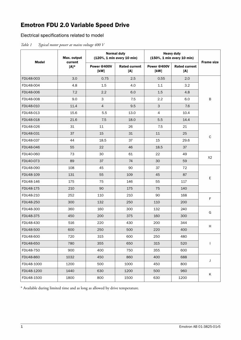
Emotron FDU 2.0 Variable Speed DriveElectrical specifications related to model
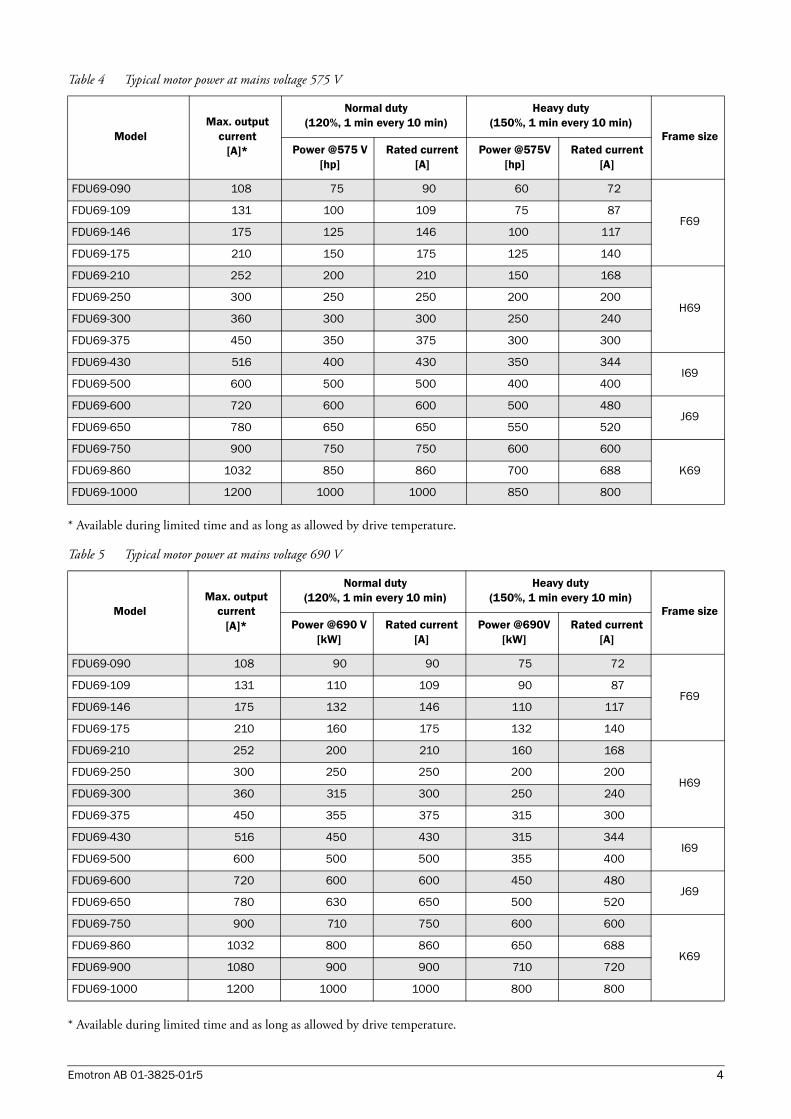
* Available during limited time and as long as allowed by drive temperature.
Table 1 Typical motor power at mains voltage 400 V
ModelMax. output
current [A]*
Normal duty (120%, 1 min every 10 min)
Heavy duty (150%, 1 min every 10 min)
Frame sizePower @400V
[kW]Rated current
[A]Power @400V
[kW]Rated current
[A]
FDU48-003 3.0 0.75 2.5 0.55 2.0
B
FDU48-004 4.8 1.5 4.0 1.1 3.2
FDU48-006 7.2 2.2 6.0 1.5 4.8
FDU48-008 9.0 3 7.5 2.2 6.0
FDU48-010 11.4 4 9.5 3 7.6
FDU48-013 15.6 5.5 13.0 4 10.4
FDU48-018 21.6 7.5 18.0 5.5 14.4
FDU48-026 31 11 26 7.5 21
CFDU48-031 37 15 31 11 25
FDU48-037 44 18.5 37 15 29.6
FDU48-046 55 22 46 18.5 37
FDU40-060 73 30 61 22 49X2
FDU40-073 89 37 74 30 59
FDU48-090 108 45 90 37 72
EFDU48-109 131 55 109 45 87
FDU48-146 175 75 146 55 117
FDU48-175 210 90 175 75 140
FDU48-210 252 110 210 90 168F
FDU48-250 300 132 250 110 200
FDU48-300 360 160 300 132 240G
FDU48-375 450 200 375 160 300
FDU48-430 516 220 430 200 344H
FDU48-500 600 250 500 220 400
FDU48-600 720 315 600 250 480
IFDU48-650 780 355 650 315 520
FDU48-750 900 400 750 355 600
FDU48-860 1032 450 860 400 688J
FDU48-1000 1200 500 1000 450 800
FDU48-1200 1440 630 1200 500 960K
FDU48-1500 1800 800 1500 630 1200
1 Emotron AB 01-3825-01r5
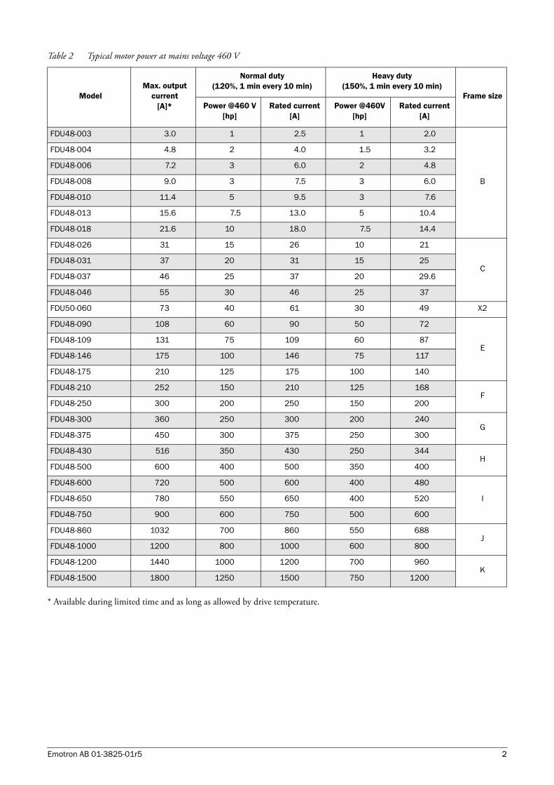
* Available during limited time and as long as allowed by drive temperature.
Table 2 Typical motor power at mains voltage 460 V
ModelMax. output
current [A]*
Normal duty (120%, 1 min every 10 min)
Heavy duty (150%, 1 min every 10 min)
Frame sizePower @460 V
[hp]Rated current
[A]Power @460V
[hp]Rated current
[A]
FDU48-003 3.0 1 2.5 1 2.0
B
FDU48-004 4.8 2 4.0 1.5 3.2
FDU48-006 7.2 3 6.0 2 4.8
FDU48-008 9.0 3 7.5 3 6.0
FDU48-010 11.4 5 9.5 3 7.6
FDU48-013 15.6 7.5 13.0 5 10.4
FDU48-018 21.6 10 18.0 7.5 14.4
FDU48-026 31 15 26 10 21
CFDU48-031 37 20 31 15 25
FDU48-037 46 25 37 20 29.6
FDU48-046 55 30 46 25 37
FDU50-060 73 40 61 30 49 X2
FDU48-090 108 60 90 50 72
EFDU48-109 131 75 109 60 87
FDU48-146 175 100 146 75 117
FDU48-175 210 125 175 100 140
FDU48-210 252 150 210 125 168F
FDU48-250 300 200 250 150 200
FDU48-300 360 250 300 200 240G
FDU48-375 450 300 375 250 300
FDU48-430 516 350 430 250 344H
FDU48-500 600 400 500 350 400
FDU48-600 720 500 600 400 480
IFDU48-650 780 550 650 400 520
FDU48-750 900 600 750 500 600
FDU48-860 1032 700 860 550 688J
FDU48-1000 1200 800 1000 600 800
FDU48-1200 1440 1000 1200 700 960K
FDU48-1500 1800 1250 1500 750 1200
Emotron AB 01-3825-01r5 2
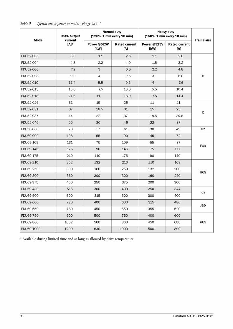
* Available during limited time and as long as allowed by drive temperature.
Table 3 Typical motor power at mains voltage 525 V
ModelMax. output
current [A]*
Normal duty (120%, 1 min every 10 min)
Heavy duty (150%, 1 min every 10 min)
Frame sizePower @525V
[kW]Rated current
[A]Power @525V
[kW]Rated current
[A]
FDU52-003 3.0 1.1 2.5 1.1 2.0
B
FDU52-004 4.8 2.2 4.0 1.5 3.2
FDU52-006 7.2 3 6.0 2.2 4.8
FDU52-008 9.0 4 7.5 3 6.0
FDU52-010 11.4 5.5 9.5 4 7.6
FDU52-013 15.6 7.5 13.0 5.5 10.4
FDU52-018 21.6 11 18.0 7.5 14.4
FDU52-026 31 15 26 11 21
CFDU52-031 37 18.5 31 15 25
FDU52-037 44 22 37 18.5 29.6
FDU52-046 55 30 46 22 37
FDU50-060 73 37 61 30 49 X2
FDU69-090 108 55 90 45 72
F69FDU69-109 131 75 109 55 87
FDU69-146 175 90 146 75 117
FDU69-175 210 110 175 90 140
FDU69-210 252 132 210 110 168
H69FDU69-250 300 160 250 132 200
FDU69-300 360 200 300 160 240
FDU69-375 450 250 375 200 300
FDU69-430 516 300 430 250 344I69
FDU69-500 600 315 500 300 400
FDU69-600 720 400 600 315 480J69
FDU69-650 780 450 650 355 520
FDU69-750 900 500 750 400 600
K69FDU69-860 1032 560 860 450 688
FDU69-1000 1200 630 1000 500 800
3 Emotron AB 01-3825-01r5
* Available during limited time and as long as allowed by drive temperature.
* Available during limited time and as long as allowed by drive temperature.
Table 4 Typical motor power at mains voltage 575 V
ModelMax. output
current [A]*
Normal duty (120%, 1 min every 10 min)
Heavy duty (150%, 1 min every 10 min)
Frame sizePower @575 V
[hp]Rated current
[A]Power @575V
[hp]Rated current
[A]
FDU69-090 108 75 90 60 72
F69FDU69-109 131 100 109 75 87
FDU69-146 175 125 146 100 117
FDU69-175 210 150 175 125 140
FDU69-210 252 200 210 150 168
H69FDU69-250 300 250 250 200 200
FDU69-300 360 300 300 250 240
FDU69-375 450 350 375 300 300
FDU69-430 516 400 430 350 344I69
FDU69-500 600 500 500 400 400
FDU69-600 720 600 600 500 480J69
FDU69-650 780 650 650 550 520
FDU69-750 900 750 750 600 600
K69FDU69-860 1032 850 860 700 688
FDU69-1000 1200 1000 1000 850 800
Table 5 Typical motor power at mains voltage 690 V
ModelMax. output
current [A]*
Normal duty (120%, 1 min every 10 min)
Heavy duty (150%, 1 min every 10 min)
Frame sizePower @690 V
[kW]Rated current
[A]Power @690V
[kW]Rated current
[A]
FDU69-090 108 90 90 75 72
F69FDU69-109 131 110 109 90 87
FDU69-146 175 132 146 110 117
FDU69-175 210 160 175 132 140
FDU69-210 252 200 210 160 168
H69FDU69-250 300 250 250 200 200
FDU69-300 360 315 300 250 240
FDU69-375 450 355 375 315 300
FDU69-430 516 450 430 315 344I69
FDU69-500 600 500 500 355 400
FDU69-600 720 600 600 450 480J69
FDU69-650 780 630 650 500 520
FDU69-750 900 710 750 600 600
K69FDU69-860 1032 800 860 650 688
FDU69-900 1080 900 900 710 720
FDU69-1000 1200 1000 1000 800 800
Emotron AB 01-3825-01r5 4

General electrical specifications
Table 6 General electrical specifications
General
Mains voltage: FDU40FDU48FDU50/52FDU69
Mains frequency:Input power factor:Output voltage:Output frequency:Output switching frequency:Efficiency at nominal load:
230-415V +10%/-15% (-10% at 230 V)230-480V +10%/-15% (-10% at 230 V)440-525V +10%/-15% 500-690V +10%/-15% 45 to 65 Hz0.950–Mains supply voltage:0–400 Hz3 kHz (adjustable 1,5-6 kHz)97% for models 003 to 01898% for models 026 to 04697.5% for models 060 to 07398% for models 090 to 1500
Control signal inputs:Analogue (differential)
Analogue Voltage/current:Max. input voltage:Input impedance:
Resolution:Hardware accuracy:Non-linearity
0-±10 V/0-20 mA via software setting+30 V/30 mA20 kΩ (voltage)250 Ω (current)11 bits + sign1% type + 1 ½ LSB fsd1½ LSB
Digital:
Input voltage:Max. input voltage:Input impedance:Signal delay:
High>9 VDC Low<4 VDC+30 VDC<3.3 VDC: 4.7 kΩ ≥3.3 VDC: 3.6 kΩ≤8 ms
Control signal outputsAnalogue
Output voltage/current:Max. output voltage:Short-circuit current (∞):Output impedance:Resolution:Maximum load impedance for currentHardware accuracy:Offset:Non-linearity:
0-10 V/0-20 mA via software setting+15 V @5 mA cont.+15 mA (voltage) +140 mA (current)10 Ω (voltage)10 bit500 Ω1.9% type fsd (voltage), 2.4% type fsd (current)3 LSB2 LSB
Digital
Output voltage:
Shortcircuit current(∞):
High>20 VDC @50 mA, >23 VDC openLow<1 VDC @50 mA100 mA max (together with +24 VDC)
Relays
Contacts 0,1 - 2 A/Umax 250 VAC or 42 VDC
References
+10VDC-10VDC+24VDC
+10 VDC @10 mA Shortcircuit current +30 mA max-10 VDC @10 mA+24 VDC Short-circuit current +100 mA max (together with Digital Outputs)
5 Emotron AB 01-3825-01r5
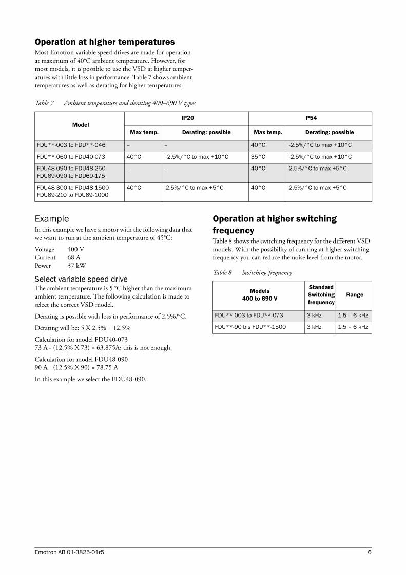
Operation at higher temperaturesMost Emotron variable speed drives are made for operation at maximum of 40°C ambient temperature. However, for most models, it is possible to use the VSD at higher temper-atures with little loss in performance. Table 7 shows ambient temperatures as well as derating for higher temperatures.
ExampleIn this example we have a motor with the following data that we want to run at the ambient temperature of 45°C:
Voltage 400 VCurrent 68 APower 37 kW
Select variable speed driveThe ambient temperature is 5 °C higher than the maximum ambient temperature. The following calculation is made to select the correct VSD model.
Derating is possible with loss in performance of 2.5%/°C.
Derating will be: 5 X 2.5% = 12.5%
Calculation for model FDU40-07373 A - (12.5% X 73) = 63.875A; this is not enough.
Calculation for model FDU48-09090 A - (12.5% X 90) = 78.75 A
In this example we select the FDU48-090.
Operation at higher switching frequencyTable 8 shows the switching frequency for the different VSD models. With the possibility of running at higher switching frequency you can reduce the noise level from the motor.
Table 7 Ambient temperature and derating 400–690 V types
Model IP20 P54
Max temp. Derating: possible Max temp. Derating: possible
FDU**-003 to FDU**-046 – – 40°C -2.5%/°C to max +10°C
FDU**-060 to FDU40-073 40°C -2.5%/°C to max +10°C 35°C -2.5%/°C to max +10°C
FDU48-090 to FDU48-250FDU69-090 to FDU69-175
– – 40°C -2.5%/°C to max +5°C
FDU48-300 to FDU48-1500FDU69-210 to FDU69-1000
40°C -2.5%/°C to max +5°C 40°C -2.5%/°C to max +5°C
Table 8 Switching frequency
Models400 to 690 V
Standard Switching frequency
Range
FDU**-003 to FDU**-073 3 kHz 1,5 – 6 kHz
FDU**-90 bis FDU**-1500 3 kHz 1,5 – 6 kHz
Emotron AB 01-3825-01r5 6
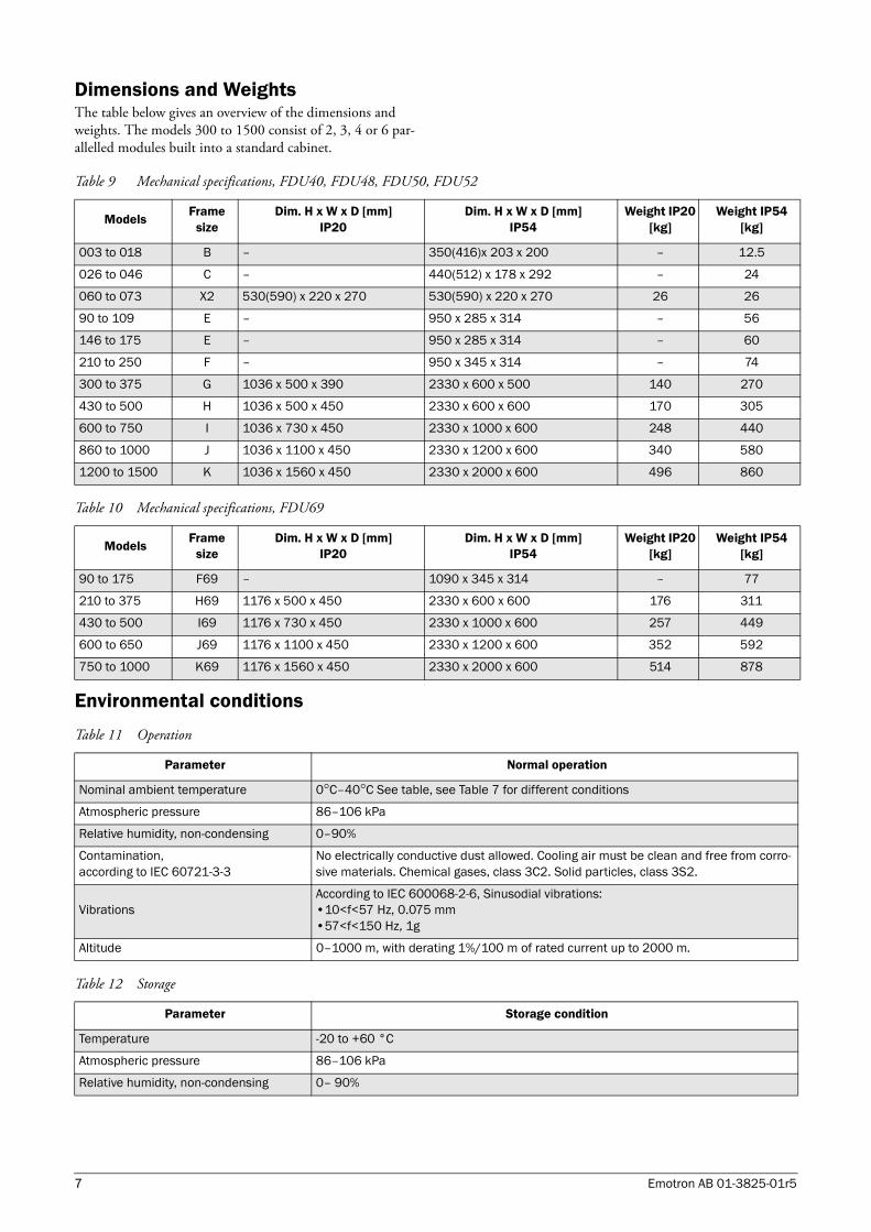
Dimensions and WeightsThe table below gives an overview of the dimensions and weights. The models 300 to 1500 consist of 2, 3, 4 or 6 par-allelled modules built into a standard cabinet.
Environmental conditions
Table 9 Mechanical specifications, FDU40, FDU48, FDU50, FDU52
Models Frame size
Dim. H x W x D [mm]IP20
Dim. H x W x D [mm] IP54
Weight IP20 [kg]
Weight IP54 [kg]
003 to 018 B – 350(416)x 203 x 200 – 12.5
026 to 046 C – 440(512) x 178 x 292 – 24
060 to 073 X2 530(590) x 220 x 270 530(590) x 220 x 270 26 26
90 to 109 E – 950 x 285 x 314 – 56
146 to 175 E – 950 x 285 x 314 – 60
210 to 250 F – 950 x 345 x 314 – 74
300 to 375 G 1036 x 500 x 390 2330 x 600 x 500 140 270
430 to 500 H 1036 x 500 x 450 2330 x 600 x 600 170 305
600 to 750 I 1036 x 730 x 450 2330 x 1000 x 600 248 440
860 to 1000 J 1036 x 1100 x 450 2330 x 1200 x 600 340 580
1200 to 1500 K 1036 x 1560 x 450 2330 x 2000 x 600 496 860
Table 10 Mechanical specifications, FDU69
Models Frame size
Dim. H x W x D [mm]IP20
Dim. H x W x D [mm] IP54
Weight IP20 [kg]
Weight IP54 [kg]
90 to 175 F69 – 1090 x 345 x 314 – 77
210 to 375 H69 1176 x 500 x 450 2330 x 600 x 600 176 311
430 to 500 I69 1176 x 730 x 450 2330 x 1000 x 600 257 449
600 to 650 J69 1176 x 1100 x 450 2330 x 1200 x 600 352 592
750 to 1000 K69 1176 x 1560 x 450 2330 x 2000 x 600 514 878
Table 11 Operation
Parameter Normal operation
Nominal ambient temperature 0°C–40°C See table, see Table 7 for different conditions
Atmospheric pressure 86–106 kPa
Relative humidity, non-condensing 0–90%
Contamination, according to IEC 60721-3-3
No electrically conductive dust allowed. Cooling air must be clean and free from corro-sive materials. Chemical gases, class 3C2. Solid particles, class 3S2.
VibrationsAccording to IEC 600068-2-6, Sinusodial vibrations:•10<f<57 Hz, 0.075 mm•57<f<150 Hz, 1g
Altitude 0–1000 m, with derating 1%/100 m of rated current up to 2000 m.
Table 12 Storage
Parameter Storage condition
Temperature -20 to +60 °C
Atmospheric pressure 86–106 kPa
Relative humidity, non-condensing 0– 90%
7 Emotron AB 01-3825-01r5
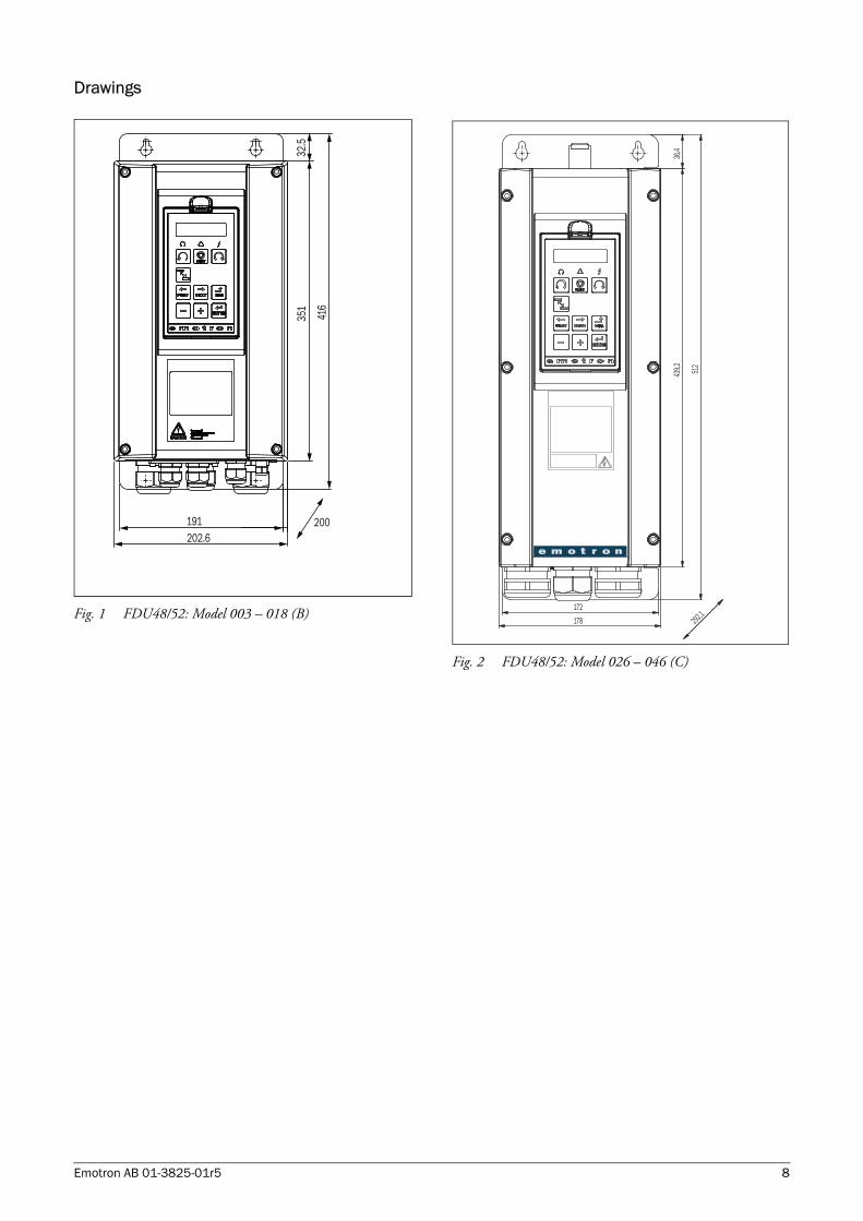
Drawings
Fig. 1 FDU48/52: Model 003 – 018 (B)
Fig. 2 FDU48/52: Model 026 – 046 (C)
202.6
416
351
32.5
191 200
292,1
36,4
439,2 51
2
172
178
Emotron AB 01-3825-01r5 8
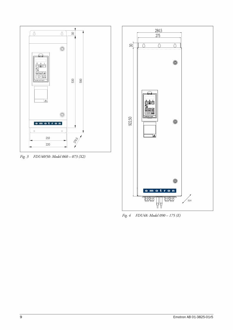
Fig. 3 FDU40/50: Model 060 – 073 (X2)
Fig. 4 FDU48: Model 090 – 175 (E)
274,5
3053
0
590
210
220
284,5275
3092
2,50
314
9 Emotron AB 01-3825-01r5
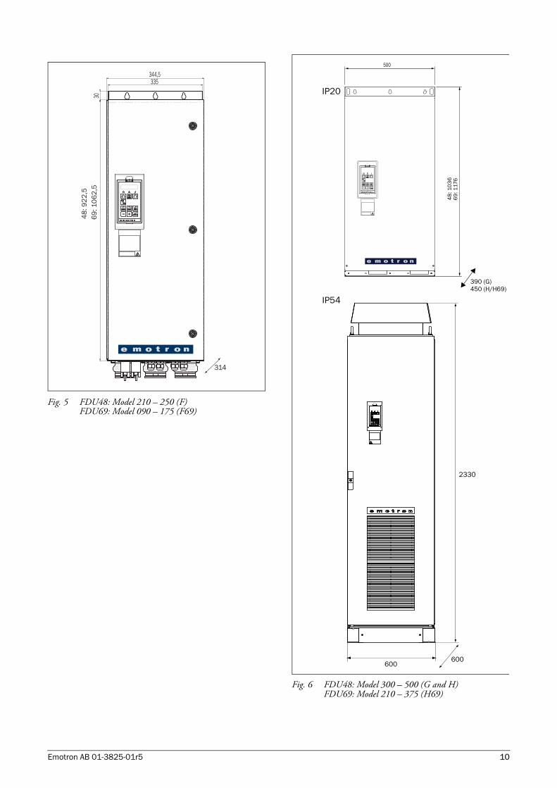
Fig. 5 FDU48: Model 210 – 250 (F)FDU69: Model 090 – 175 (F69)
Fig. 6 FDU48: Model 300 – 500 (G and H)FDU69: Model 210 – 375 (H69)
335344,5
30
314
48
: 92
2,5
69
: 10
62
,5
600
2330
600
500
48
: 10
36
69
: 117
6
390 (G)450 (H/H69)
IP20
IP54
Emotron AB 01-3825-01r5 10
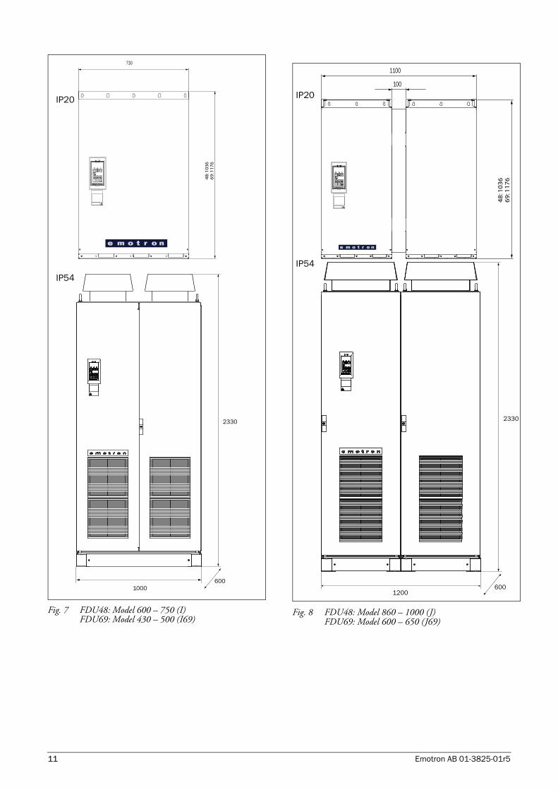
Fig. 7 FDU48: Model 600 – 750 (I)FDU69: Model 430 – 500 (I69)
Fig. 8 FDU48: Model 860 – 1000 (J)FDU69: Model 600 – 650 (J69)
730
48
: 10
36
69
: 11
76
600
2330
1000
IP20
IP54
600
600
2330
1200
1100
100
48
: 10
36
69
: 11
76
IP20
IP54
11 Emotron AB 01-3825-01r5
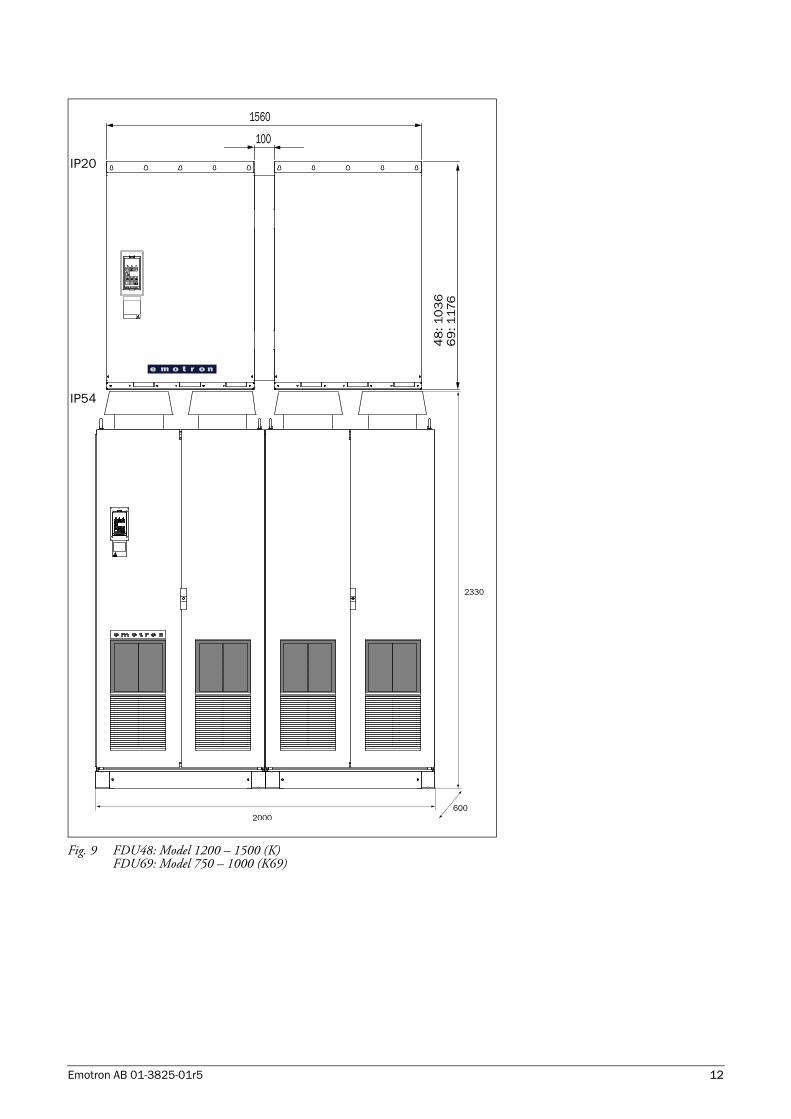
Fig. 9 FDU48: Model 1200 – 1500 (K)FDU69: Model 750 – 1000 (K69)
600
2330
2000
600
100
1560
48
: 10
36
69
: 117
6
IP20
IP54
Emotron AB 01-3825-01r5 12
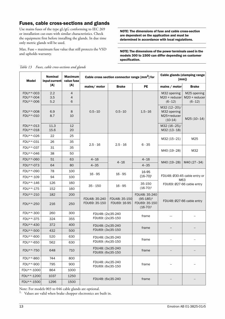
Fuses, cable cross-sections and glandsUse mains fuses of the type gL/gG conforming to IEC 269 or installation cut-outs with similar characteristics. Check the equipment first before installing the glands. In due time only metric glands will be used.
Max. Fuse = maximum fuse value that still protects the VSD and upholds warranty.
Note: For models 003 to 046 cable glands are optional. 1. Values are valid when brake chopper electronics are built in.
NOTE: The dimensions of fuse and cable cross-section are dependent on the application and must be determined in accordance with local regulations.
NOTE: The dimensions of the power terminals used in the models 300 to 1500 can differ depending on customer specification.
Table 13 Fuses, cable cross-sections and glands
Model Nominal
input current [A]
Maximum value fuse
[A]
Cable cross section connector range [mm2] for Cable glands (clamping range [mm])
mains/ motor Brake PE mains / motor Brake
FDU**-003FDU**-004FDU**-006
2.23.55.2
446
0.5–10 0.5–10 1.5–16
M32 openingM20 + reducer
(6–12)
M25 openingM20 + reducer
(6–12)
FDU**-008FDU**-010
6.98.7
810
M32 (12–20)/M32 openingM25+reducer
(10-14) M25 (10–14)
FDU**-013FDU**-018
11.315.6
1220
M32 (16–25)/M32 (13–18)
FDU**-026 22 25
2.5 - 16 2.5 - 16 6 - 35
M32 (15–21) M25FDU**-031 26 35
FDU**-037 31 35M40 (19–28) M32
FDU**-046 38 50
FDU**-060 51 63 4–164–16
4–16M40 (19–28) M40 (27–34)
FDU**-073 64 80 4–35 4–35
FDU**-090 78 10016 - 95 16 - 95 16-95
(16-70)¹ FDU48: Ø30-45 cable entry or M63
FDU69: Ø27-66 cable entry
FDU**-109 94 100
FDU**-146 126 16035 - 150 16 - 95 35-150
(16-70)¹FDU**-175 152 160
FDU**-210 182 200FDU48: 35-240FDU69: 35-150
FDU48: 35-150FDU69: 16-95
FDU48: 35-240 (95-185)¹
FDU69: 35-150 (16-70)¹
FDU48: Ø27-66 cable entryFDU**-250 216 250
FDU**-300 260 300 FDU48: (2x)35-240FDU69: (2x)35-150 frame --- --
FDU**-375 324 355
FDU**-430 372 400 FDU48: (2x)35-240FDU69: (3x)35-150 frame -- --
FDU**-500 432 500
FDU**-600 520 630 FDU48: (3x)35-240FDU69: (4x)35-150 frame -- --
FDU**-650 562 630
FDU**-750 648 710 FDU48: (3x)35-240FDU69: (6x)35-150 frame -- --
FDU**-860 744 800FDU48: (4x)35-240FDU69: (6x)35-150 frame -- --FDU**-900 795 900
FDU**-1000 864 1000
FDU**-1200 1037 1250FDU48: (6x)35-240 frame -- --
FDU**-1500 1296 1500
13 Emotron AB 01-3825-01r5
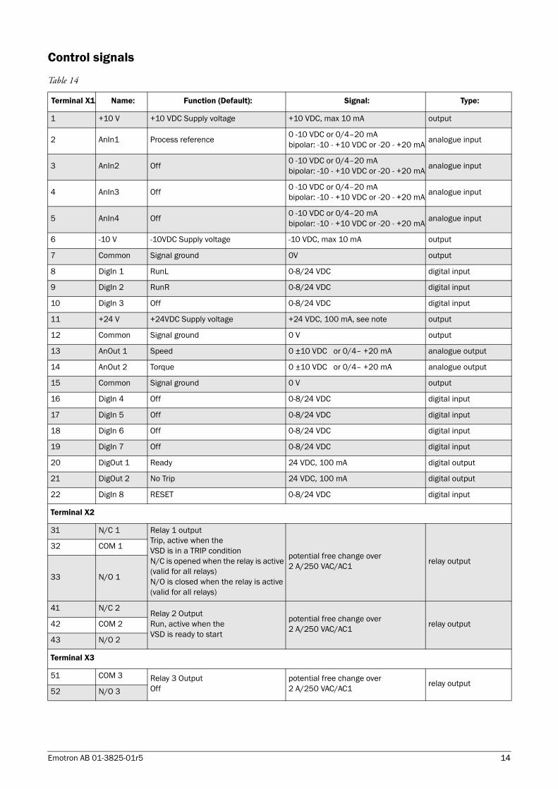
Control signals
Table 14
Terminal X1 Name: Function (Default): Signal: Type:
1 +10 V +10 VDC Supply voltage +10 VDC, max 10 mA output
2 AnIn1 Process reference 0 -10 VDC or 0/4–20 mAbipolar: -10 - +10 VDC or -20 - +20 mA analogue input
3 AnIn2 Off 0 -10 VDC or 0/4–20 mAbipolar: -10 - +10 VDC or -20 - +20 mA analogue input
4 AnIn3 Off 0 -10 VDC or 0/4–20 mAbipolar: -10 - +10 VDC or -20 - +20 mA analogue input
5 AnIn4 Off 0 -10 VDC or 0/4–20 mAbipolar: -10 - +10 VDC or -20 - +20 mA analogue input
6 -10 V -10VDC Supply voltage -10 VDC, max 10 mA output
7 Common Signal ground 0V output
8 DigIn 1 RunL 0-8/24 VDC digital input
9 DigIn 2 RunR 0-8/24 VDC digital input
10 DigIn 3 Off 0-8/24 VDC digital input
11 +24 V +24VDC Supply voltage +24 VDC, 100 mA, see note output
12 Common Signal ground 0 V output
13 AnOut 1 Speed 0 ±10 VDC or 0/4– +20 mA analogue output
14 AnOut 2 Torque 0 ±10 VDC or 0/4– +20 mA analogue output
15 Common Signal ground 0 V output
16 DigIn 4 Off 0-8/24 VDC digital input
17 DigIn 5 Off 0-8/24 VDC digital input
18 DigIn 6 Off 0-8/24 VDC digital input
19 DigIn 7 Off 0-8/24 VDC digital input
20 DigOut 1 Ready 24 VDC, 100 mA digital output
21 DigOut 2 No Trip 24 VDC, 100 mA digital output
22 DigIn 8 RESET 0-8/24 VDC digital input
Terminal X2
31 N/C 1 Relay 1 outputTrip, active when theVSD is in a TRIP conditionN/C is opened when the relay is active (valid for all relays)N/O is closed when the relay is active (valid for all relays)
potential free change over2 A/250 VAC/AC1 relay output
32 COM 1
33 N/O 1
41 N/C 2Relay 2 OutputRun, active when theVSD is ready to start
potential free change over2 A/250 VAC/AC1 relay output42 COM 2
43 N/O 2
Terminal X3
51 COM 3 Relay 3 OutputOff
potential free change over2 A/250 VAC/AC1 relay output
52 N/O 3
Emotron AB 01-3825-01r5 14

Emot
ron
AB 0
1-38
25-0
1r5
2009
-04-
15
Emotron AB, Mörsaregatan 12, SE-250 24 Helsingborg, SwedenTel: +46 42 16 99 00, Fax: +46 42 16 99 49
E-mail: [email protected]: www.emotron.com