Embed Size (px)
Citation preview

Emulation und Emulation und Rapid Prototyping
Hw-Sw-Co-DesigngWS 2008/09
Rolf Drechsler
Informatik Universität BremenInformatik, Universität Bremen
Nach: Jürgen Teich Universität ErlangenNach: Jürgen Teich, Universität Erlangen

Simulation von komplexen ICs
Design level Descriptionlanguage Primitives Simulation time
(instructions/cycle)
Algorithm HLL Instruction sets 10-100
Architecture HLL, HDL Functionalblocks 1K-10K
Registertransfer HDL RTL primitives 1M-10M
Logic HDL, netlist Logic gates 10M-100M

Beschleunigung
• Emulation (Nachbildung, Nachahmung)– Simulationselemente werden als HW bereitgestelltg
– Höhere Abarbeitungsgeschwindigkeit
– Komplexer in der Handhabung
• Rapid‐Prototyping (Muster)p yp g ( )– Funktionsfähige Implementierung
– Heterogene Elemente
– Reduzierte Anforderungen an den Entwurf
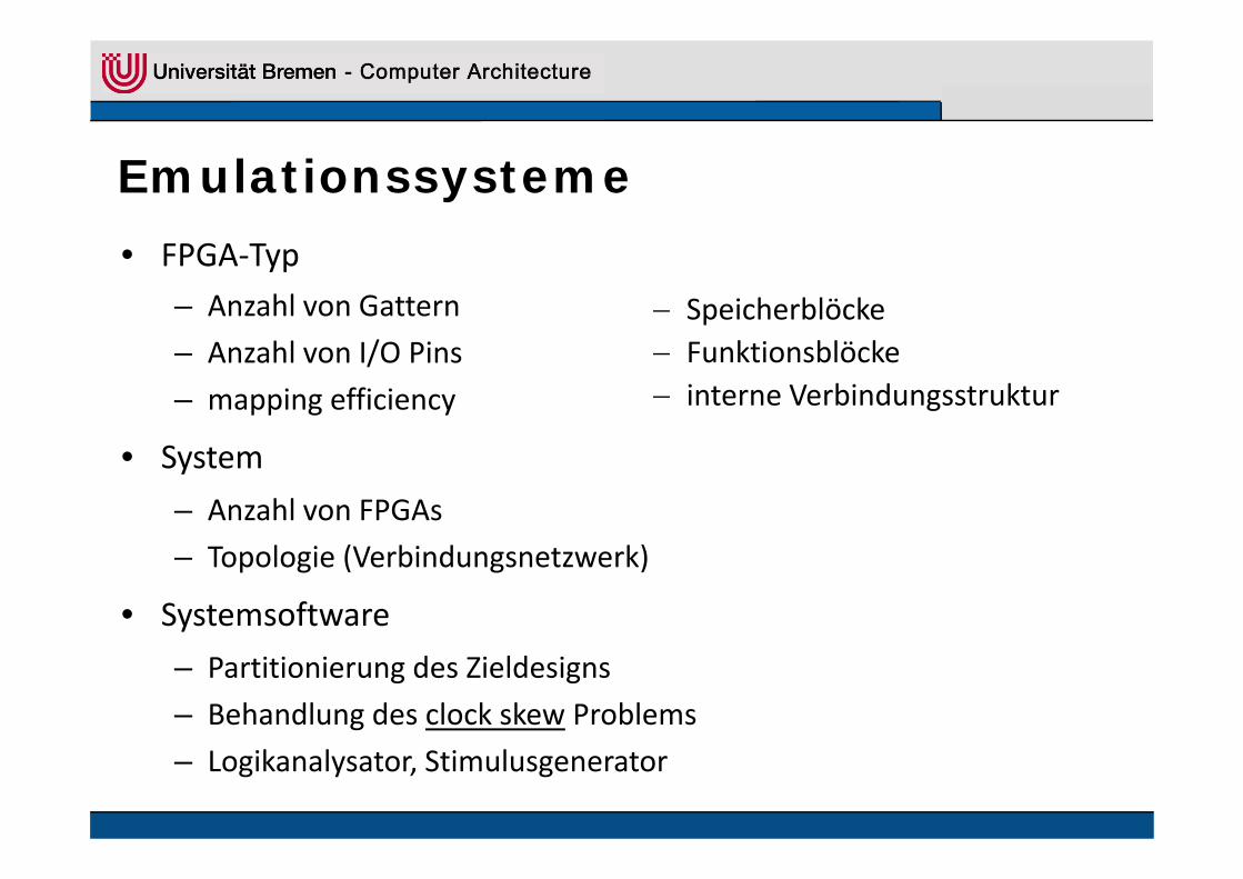
Emulationssysteme
• FPGA‐Typ– Anzahl von Gattern
/− Speicherblöcke
– Anzahl von I/O Pins
– mapping efficiency
− Funktionsblöcke− interne Verbindungsstruktur
• System
– Anzahl von FPGAs
– Topologie (Verbindungsnetzwerk)
• Systemsoftware
– Partitionierung des Zieldesigns
– Behandlung des clock skew Problems
– Logikanalysator, Stimulusgenerator
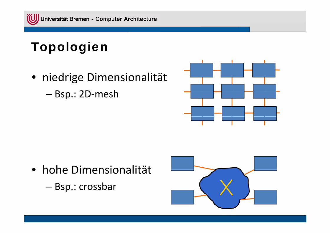
Topologien
• niedrige Dimensionalitäth– Bsp.: 2D‐mesh
• hohe Dimensionalität• hohe Dimensionalität– Bsp.: crossbar
d i f ti l d i ti
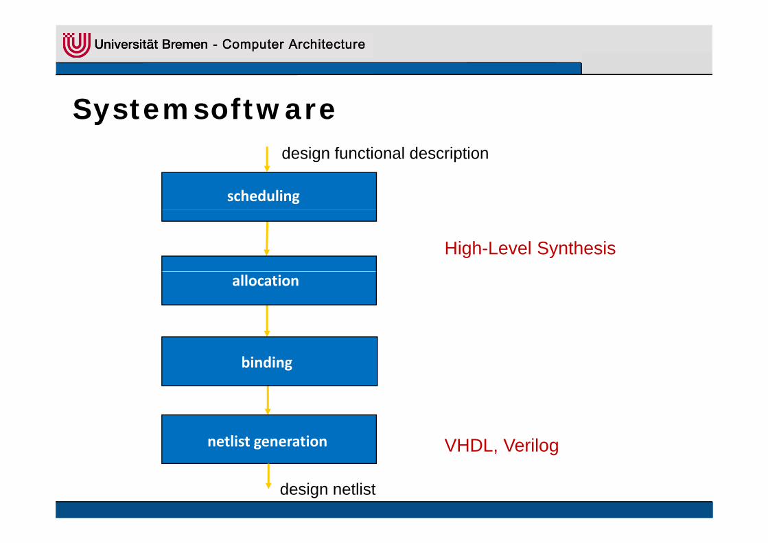
Systemsoftware
scheduling
design functional description
High-Level Synthesis
allocation
binding
netlist generation VHDL, Verilog
design netlist

d i tli t
Systemsoftware
technology mapping
design netlist
structural partitioning
design analysis
p g
partition, place, and route
FPGA compilation
FPGA configuration bits

I/O Pin Beschränkung
• Rent’s Rule (Gatter und I/O Pins einer Partition)
fGP ∝GP
P … Anzahl der I/O Pins
G … Anzahl der Gatter
f ~ 0.5 bei strukturierten Designs
f > 0 5 b i d l if > 0.5 bei random logic

I/O Pin Beschränkung - Bsp.
I/O Pins
700
800Cache controller chip
500
600
700
300
400Xilinx XC4000
100
200
100 1000 10000 100000 FPGA Partition Gates

l i i ll b (hi hi h)
Enterprise System• Topologie: partieller Crossbar (hierarchisch)
• Systemsoftware: fügt Verzögerungen einy g g g
FPGA1 FPGA4FPGA3FPGA2FPGA1A B C D A B C D A B C D A B C D
A pins B pins C pins D pinscrossbar chip crossbar chip crossbar chip crossbar chip

Virtual Wires
• Topologie: 2D‐mesh
• Systemsoftware• Systemsoftware
– mehrere logische Leitungen werden auf wenigen physikalischen Leitungen gemultiplextphysikalischen Leitungen gemultiplext
– alle Register werden mit dem virtual clock getaktet;
di P i d i t ß d i b hb t FPGAdie Periode ist genau so groß, dass zwei benachbarte FPGAs
kommunizieren können (Trade‐Off)
b i d P titi i ibt k i I/O Pi B h ä k– bei der Partitionierung gibt es keine I/O Pin Beschränkungen
mehr, daher erreicht man gute FPGA‐Auslastungen

Virtual Wires - Beispiel (1)

Virtual Wires - Beispiel (2)

Emulation - Beispiele
MicroSPARC II SuperSPARC II UltraSPARC I
Q i ktQuickturn systems 1 2 5
Emulation gates 0.25 M 0.55 M 1 Mgates
Emulation frequency 750 kHz 350 kHz 350 kHz
Critical bugs found 1 0 1
D iDesign development 3 weeks 3 weeks 3 weeks
Full config. time 24 hours 24 hours 36 hourstime

Emulation - Beispiele
• Prototypen mit heterogenen Komponenten
• Rapid Prototyping Systeme bietenRapid Prototyping Systeme bieten– Module
• Prozessoren
• Spezialchips (ASICs)
• FPGAs
• Speicher
– flexible Verbindungsstrukturflexible Verbindungsstruktur
• FPGAs
• FPICS (field‐programmable interconnects)FPICS (field programmable interconnects)

Aptix Explorer Toolflow

Aptix Explorer MP3

SYDER Virtex2
• Xilinx Virtex Chip
• viele I/O Pins (~176)/ ( )
• PCI ‐ Bus

PAPTOR
• dynamisch rekonfigurierbar
• Zugriff auf internen Busg
• wenig I/O Pins

FLEX 10 (Altera)
• 10K – 250k typical gates
• Anzeigeelementeg

Excalibur (Altera)
• Combining logic, memory, and a processor core
• APEX device familyAPEX device family – ranges from 30,000 to over 1.5 million gates
• Combination of three different types structuresCombination of three different types structures– look‐up tables (LUTs)
like those found in FLEX 10K and FLEX 6000 devices;
– product‐term blockslike those found in MAX 7000 devices
– enhanced embedded memory blockslike those found in FLEX 10KE devices

APEX device family

Zusammenfassung
• Simulation von komplexen IC– oft zu langsam
• Emulation– HW‐ Unterstützung
V k ü f h K f G Eb– Verknüpfung homogener Komponenten auf Gatter‐Ebene– Probleme: Gatterkapazität, Topologie, I/O
• Rapid Prototyping• Rapid Prototyping– Verknüpfung heterogener Komponenten
• auf Gatter‐Ebene und auf Architektur‐Ebene– Aptix Explorer, Spyder, Raptor, Flex10, Excalibur
verfügbar im FB14 und FB17F h St di d Di l b it• Forschung, Studien‐ und Diplomarbeiten


![Apple ][ Emulation on an AVR Microcontroller Emulation ... · Apple ][ Emulation on an AVR Microcontroller Emulation eines Apple ][ auf einem AVR Mikrocontroller Maximilian Strauch](https://img.pdfslide.net/doc/110x75/5d494b4588c99334058bd1f6/apple-emulation-on-an-avr-microcontroller-emulation-apple-emulation.jpg)