Embed Size (px)
Citation preview
QAiST is supported by:
Project IEE/08/593/SI2.529236
EN-12976 GUIDE OF PROCEDURES FOR RELIABILITY TESTS OF FACTORY MADE SYSTEMS
Deliverable D3.2
CENER
A.G.de Jalón, E.Mateu, F.Sallaberry
TÜV
Ulrich Fritzsche
Version 02.05
Date: 28.05.2012
EN-12976 Guide for reliability test procedures of factory made solar thermal systems
Contact Info
CENER Ciudad Innovación,7 31621 Sarriguren- Navarra-Spain Tel. : +34 948252800 Fax : +34 948270774 E-mail: [email protected]
TÜV Rheinland Energie und Umwelt GmbH Am Grauen Stein 51105 Köln Tel. : +49 221 806 4105 Fax : +49 221 806 1350 E-mail: [email protected]
Project IEE/08/593/SI2.529236
EN-12976 Guide for reliability test procedures of factory
made solar thermal systems
Page 2 of 25
Contents
1 Purpose and scope .......................................................................................................................... 3
2 Referenced standards ..................................................................................................................... 3
3 Definitions ........................................................................................................................................ 4
3.1 Systems with separable collector ............................................................................................ 4
3.2 Systems with none separable collectors ................................................................................. 4
4 Required reliability tests for factory made systems ......................................................................... 5
4.1 System Reliability tests according to EN 12976-2 and system and component requirements according to EN 12976-1 ..................................................................................................................... 5
4.2 Additional required collector reliability tests according to EN 12975-1 ................................... 5
4.3 Applicable tests to different factory made system types ......................................................... 6
5 System reliability tests according to EN 12976-2 ............................................................................ 6
5.1 Freeze resistance test ............................................................................................................. 6
5.2 Over temperature protection test ............................................................................................. 7
5.3 Pressure resistance ................................................................................................................. 8
5.4 Water contamination ................................................................................................................ 9
5.5 Lightning protection ............................................................................................................... 10
5.6 Safety Equipment .................................................................................................................. 13
5.7 Labeling ................................................................................................................................. 14
5.8 Reverse flow protection ......................................................................................................... 14
5.9 Electrical safety ..................................................................................................................... 14
6 Additional required collector reliability tests according to EN 12975-1 ......................................... 16
6.1 High temperature resistance ................................................................................................. 16
6.2 Exposure test ......................................................................................................................... 17
6.3 External thermal shock test ................................................................................................... 17
6.4 Internal thermal shock test .................................................................................................... 18
6.5 Rain penetration test ............................................................................................................. 18
6.6 Mechanical load test .............................................................................................................. 19
6.7 Determination of the collector stagnation temperature ......................................................... 22
6.8 Final Inspection of the collector components ........................................................................ 23
7 System and component requirements according to EN 12976-1 ................................................. 24
7.1 Suitable for drinking water ..................................................................................................... 24
7.2 Materials ................................................................................................................................ 24
7.3 Components and pipework .................................................................................................... 24
7.4 Resistance to external influences .......................................................................................... 25
7.5 Documentation ...................................................................................................................... 25
Project IEE/08/593/SI2.529236
EN-12976 Guide for reliability test procedures of factory
made solar thermal systems
Page 3 of 25
1 Purpose and scope
The purpose of this guide is to form a complement to the EN 12976 standard, focusing on parts 1 and 2 related to testing of solar thermal factory made systems. It is intended to support in the interpretation and application of the standard. The guide has been developed with two different target groups and objectives in mind.
A guide directed to established and new test laboratories for system testing. The main purpose here is to give a quick introduction to the standard for new laboratories and in general to contribute to a uniform interpretation of the standard and presentation of results. A guide directed to manufacturers and importers of systems. Here, the purpose is to give a very light introduction to the standard and to explain how it is used for type testing as well as for innovation and development support.
During the writing of this guide, the EN 12976:2006 is currently under revision and some significant changes are expected in the new version planned for 2012/ 2013. As these changes cannot be predicted at present this guide will primarily be based on the 2006 version of the standard. However significant changes that are most likely to be part of the next version of the standard are indicated as far as possible.
Please note that the only official document in this context is the standard itself. For up to date detailed information always refer to the latest version of the full standard. An updated version of the standard is expected during 2012/13.
2 Referenced standards
EN 12975-1:2006, Thermal solar systems and components – Solar collectors – Part 1: General Requirements
EN 12975-2:2006, Thermal solar systems and components – Solar collectors – Part 2: Test methods
EN 12976-1:2006,, Thermal solar systems and components – Factory made systems – Part 1: General Requirements
EN 12976-2:2000, Thermal solar systems and components – Factory made systems – Part 2: Test methods
EN ISO 9488, Solar energy – Vocabulary (ISO 9488:1999)
ISO 9459-2: 1995, Solar Heating – Domestic water heating systems – Part 2: Outdoor test methods for system performance characterization and yearly performance prediction of solar-only systems
ISO 9459-5: 1995, Solar Heating – Domestic water heating systems – Part 5: System performance characterization by means of whole-system tests and computer simulation
Project IEE/08/593/SI2.529236
EN-12976 Guide for reliability test procedures of factory
made solar thermal systems
Page 4 of 25
3 Definitions
To define the requested number of tests and the way to proceed, it is essential to differ between separable and none separable system-collector units. Therefore a clear definition is necessary.
3.1 Systems with separable collector
A collector is separable when all applicable functional tests according to EN 12975-2 can be performed with the single collector. (For some collector types like tube collectors it was agreed, that the negative mechanical load test is not applicable.)
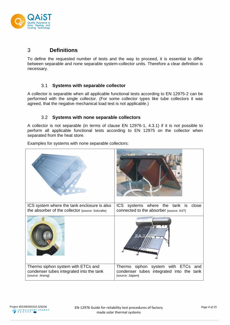
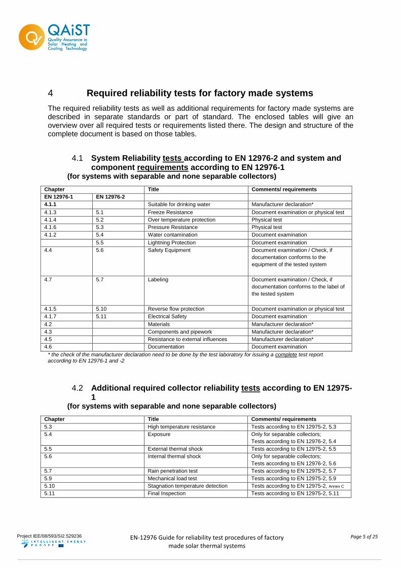
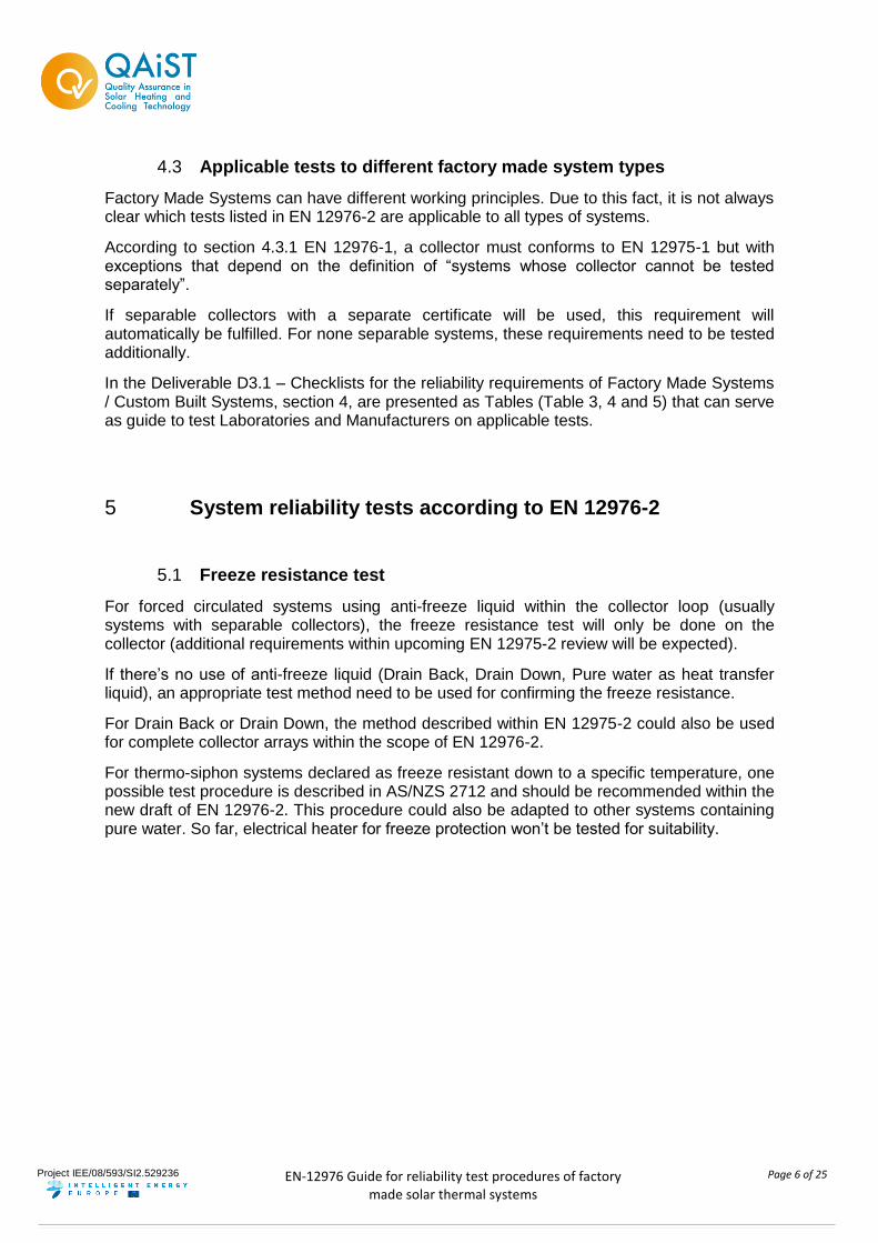
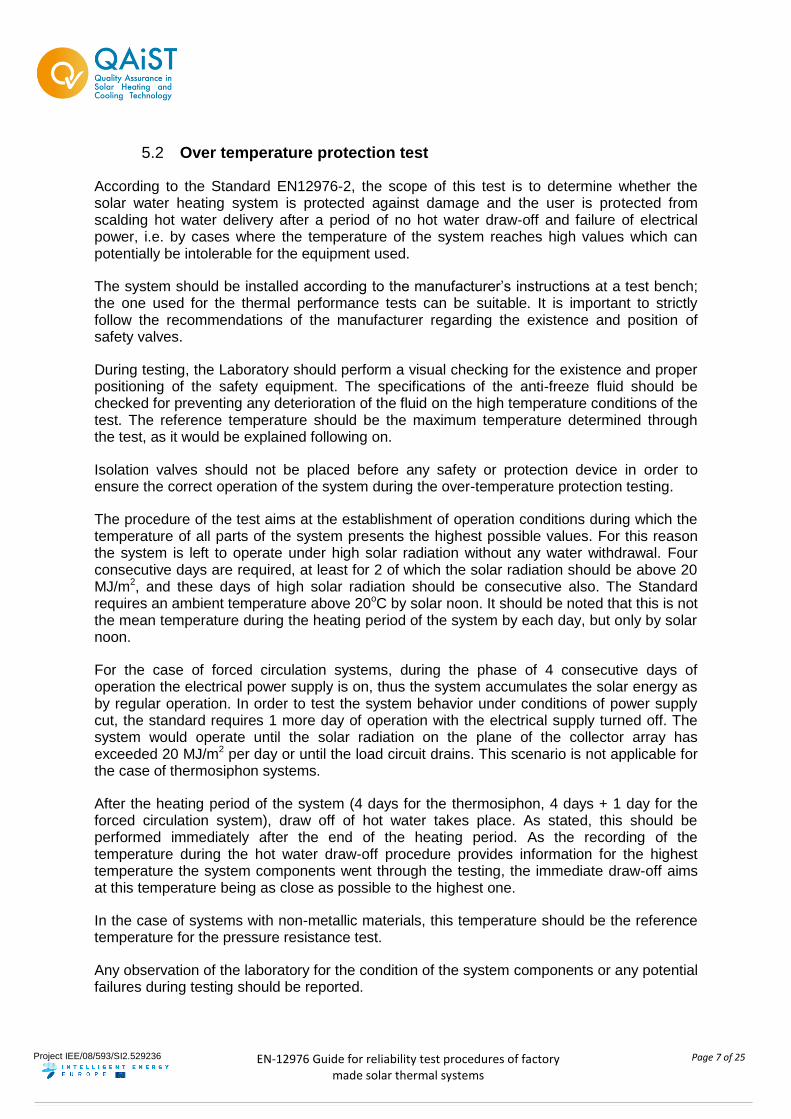
3.2 Systems with none separable collectors
A collector is not separable (in terms of clause EN 12976-1, 4.3.1) if it is not possible to perform all applicable functional tests according to EN 12975 on the collector when separated from the heat store.
Examples for systems with none separable collectors:
ICS system where the tank enclosure is also the absorber of the collector [source: Solcrafte]
ICS systems where the tank is close connected to the absorber [source: AST]
Thermo siphon system with ETCs and condenser tubes integrated into the tank [source: Jineng]
Thermo siphon system with ETCs and condenser tubes integrated into the tank [source: Jiajiare]
Project IEE/08/593/SI2.529236
EN-12976 Guide for reliability test procedures of factory
made solar thermal systems
Page 5 of 25
4 Required reliability tests for factory made systems
The required reliability tests as well as additional requirements for factory made systems are described in separate standards or part of standard. The enclosed tables will give an overview over all required tests or requirements listed there. The design and structure of the complete document is based on those tables.
4.1 System Reliability tests according to EN 12976-2 and system and component requirements according to EN 12976-1
(for systems with separable and none separable collectors)
Chapter Title Comments/ requirements
EN 12976-1 EN 12976-2
4.1.1 Suitable for drinking water Manufacturer declaration*
4.1.3 5.1 Freeze Resistance Document examination or physical test
4.1.4 5.2 Over temperature protection Physical test
4.1.6 5.3 Pressure Resistance Physical test
4.1.2 5.4 Water contamination Document examination
5.5 Lightning Protection Document examination
4.4 5.6 Safety Equipment Document examination / Check, if
documentation conforms to the
equipment of the tested system
4.7 5.7 Labeling Document examination / Check, if
documentation conforms to the label of
the tested system
4.1.5 5.10 Reverse flow protection Document examination or physical test
4.1.7 5.11 Electrical Safety Document examination
4.2 Materials Manufacturer declaration*
4.3 Components and pipework Manufacturer declaration*
4.5 Resistance to external influences Manufacturer declaration*
4.6 Documentation Document examination
* the check of the manufacturer declaration need to be done by the test laboratory for issuing a complete test report according to EN 12976-1 and -2
4.2 Additional required collector reliability tests according to EN 12975-1
(for systems with separable and none separable collectors)
Chapter Title Comments/ requirements
5.3 High temperature resistance Tests according to EN 12975-2, 5.3
5.4 Exposure Only for separable collectors;
Tests according to EN 12976-2, 5.4
5.5 External thermal shock Tests according to EN 12975-2, 5.5
5.6 Internal thermal shock Only for separable collectors;
Tests according to EN 12976-2, 5.6
5.7 Rain penetration test Tests according to EN 12975-2, 5.7
5.9 Mechanical load test Tests according to EN 12975-2, 5.9
5.10 Stagnation temperature detection Tests according to EN 12975-2, Annex C
5.11 Final Inspection Tests according to EN 12975-2, 5.11
Project IEE/08/593/SI2.529236
EN-12976 Guide for reliability test procedures of factory
made solar thermal systems
Page 6 of 25
4.3 Applicable tests to different factory made system types
Factory Made Systems can have different working principles. Due to this fact, it is not always clear which tests listed in EN 12976-2 are applicable to all types of systems.
According to section 4.3.1 EN 12976-1, a collector must conforms to EN 12975-1 but with exceptions that depend on the definition of “systems whose collector cannot be tested separately”.
If separable collectors with a separate certificate will be used, this requirement will automatically be fulfilled. For none separable systems, these requirements need to be tested additionally.
In the Deliverable D3.1 – Checklists for the reliability requirements of Factory Made Systems / Custom Built Systems, section 4, are presented as Tables (Table 3, 4 and 5) that can serve as guide to test Laboratories and Manufacturers on applicable tests.
5 System reliability tests according to EN 12976-2
5.1 Freeze resistance test
For forced circulated systems using anti-freeze liquid within the collector loop (usually systems with separable collectors), the freeze resistance test will only be done on the collector (additional requirements within upcoming EN 12975-2 review will be expected).
If there’s no use of anti-freeze liquid (Drain Back, Drain Down, Pure water as heat transfer liquid), an appropriate test method need to be used for confirming the freeze resistance.
For Drain Back or Drain Down, the method described within EN 12975-2 could also be used for complete collector arrays within the scope of EN 12976-2.
For thermo-siphon systems declared as freeze resistant down to a specific temperature, one possible test procedure is described in AS/NZS 2712 and should be recommended within the new draft of EN 12976-2. This procedure could also be adapted to other systems containing pure water. So far, electrical heater for freeze protection won’t be tested for suitability.
Project IEE/08/593/SI2.529236
EN-12976 Guide for reliability test procedures of factory
made solar thermal systems
Page 7 of 25
5.2 Over temperature protection test
According to the Standard EN12976-2, the scope of this test is to determine whether the solar water heating system is protected against damage and the user is protected from scalding hot water delivery after a period of no hot water draw-off and failure of electrical power, i.e. by cases where the temperature of the system reaches high values which can potentially be intolerable for the equipment used.
The system should be installed according to the manufacturer’s instructions at a test bench; the one used for the thermal performance tests can be suitable. It is important to strictly follow the recommendations of the manufacturer regarding the existence and position of safety valves.
During testing, the Laboratory should perform a visual checking for the existence and proper positioning of the safety equipment. The specifications of the anti-freeze fluid should be checked for preventing any deterioration of the fluid on the high temperature conditions of the test. The reference temperature should be the maximum temperature determined through the test, as it would be explained following on.
Isolation valves should not be placed before any safety or protection device in order to ensure the correct operation of the system during the over-temperature protection testing.
The procedure of the test aims at the establishment of operation conditions during which the temperature of all parts of the system presents the highest possible values. For this reason the system is left to operate under high solar radiation without any water withdrawal. Four consecutive days are required, at least for 2 of which the solar radiation should be above 20 MJ/m2, and these days of high solar radiation should be consecutive also. The Standard requires an ambient temperature above 20oC by solar noon. It should be noted that this is not the mean temperature during the heating period of the system by each day, but only by solar noon.
For the case of forced circulation systems, during the phase of 4 consecutive days of operation the electrical power supply is on, thus the system accumulates the solar energy as by regular operation. In order to test the system behavior under conditions of power supply cut, the standard requires 1 more day of operation with the electrical supply turned off. The system would operate until the solar radiation on the plane of the collector array has exceeded 20 MJ/m2 per day or until the load circuit drains. This scenario is not applicable for the case of thermosiphon systems.
After the heating period of the system (4 days for the thermosiphon, 4 days + 1 day for the forced circulation system), draw off of hot water takes place. As stated, this should be performed immediately after the end of the heating period. As the recording of the temperature during the hot water draw-off procedure provides information for the highest temperature the system components went through the testing, the immediate draw-off aims at this temperature being as close as possible to the highest one.
In the case of systems with non-metallic materials, this temperature should be the reference temperature for the pressure resistance test.
Any observation of the laboratory for the condition of the system components or any potential failures during testing should be reported.
Project IEE/08/593/SI2.529236
EN-12976 Guide for reliability test procedures of factory
made solar thermal systems
Page 8 of 25
5.3 Pressure resistance
According to the Standard EN12976-2, the purpose of this test is to evaluate hydraulic pressure rating of all components and interconnections of a solar water heating system when installed according to the manufacturer’s instructions. For this reason, the system fluid circuits are pressurized through a pressure source installed by the testing laboratory.
The system should be installed according to the manufacturer’s instructions at a test bench; the one used for the performance tests can be suitable. It is important to strictly follow the recommendations of the manufacturer regarding the existence and position of safety valves.
During testing, the Laboratory should perform a visual checking for the existence and proper positioning of the safety equipment. The pressure relief valves should be disabled, to prevent their opening during testing.
According to EN 12976-2, the pressure source, equipped with an isolation valve is connected on the cold water inlet of the storage tank loop, using water as the test fluid. The isolation valve ensures that the imposed pressure remains constant during the test. The pressure gauge, equipped with a bleed valve, is installed at the hot water outlet of the system. In case the device of the manufacturer includes pressure source and gauge on one body, it can be installed at the cold water inlet.
The pressure should be increased gradually in order to prevent any sudden failure of the system equipment. If the tester observes optically or by sound any kind of deformation during the pressure increase, the test should be stopped and the manufacturer should be informed. The pressure of the test should be 1.5 times the one the manufacturer stated as maximum working pressure.
After this pressure has been reached, the operation of the isolation valve on the pressure source device ensures that the system remains on these conditions for 15 minutes. For systems with non-metallic materials, the duration of the test should be 1h instead. For this kind of materials, the circuit shall be at the highest temperature measured by the over-temperature test (the recommendation of the standard for highest temperature +10oC is not applicable; the temperature should be reached by stagnation under high irradiation). In order to achieve the required over-temperature conditions for the case of systems with non-metallic materials, the test can be combined with the over temperature protection one. Also the possibility to reach this temperature through the use of the back-up heating source of the system (if available), or any other external heating source provided by the laboratory can be feasible.
Within the upcoming revision of the standard, there might be the requirement for systems with non-metallic materials, that the pressure resistance test need to carried out after the over temperature test
In the case the system presents separate storage tank and collector loop, the collector loop should be filled at ambient pressure, in order to prevent any effect on the heat exchanger due to the high difference of pressure between the open and closed loop. Within the recent standard, this procedure is not explicitly explained, but it was agreed to operate in this way.
Also for this case, the test is repeated accordingly for the collector loop also. The heat transfer fluid recommended by the manufacturer should be used. The storage tank loop should be filled with water at ambient pressure.
Project IEE/08/593/SI2.529236
EN-12976 Guide for reliability test procedures of factory
made solar thermal systems
Page 9 of 25
The pressure readings by the beginning and end of the 15 min (or 1 hour) period, as well as any observation of the testing laboratory on the effects of pressure on the system parts should be reported. If the pressure drops more than 10% of the pressure readings at the beginning of the test, the test is considered as failed (according to EN 12976-1:2006 4.1.6). Since elastic deformation after the initial pressurizing of the loop may lead to a pressure drop greater than 10% of the initial value, the initial pressure should be restored and the waiting period repeated at least one time.
It might be necessary to include an isolation valve for pressure resistance testing if a disabling of the safety valve itself for this test is not possible (e,g, by a pressure resistant screwed cap). If so, the insulation valve shall not be operate during all other test sequences. This needs to be guaranteed in a proper way to ensure the safe operation of the system.
5.4 Water contamination
This standard dealt with the means to be used to prevent the pollution of potable water inside premise and the general requirements of protection devises to avoid pollution by backflow.
Enclosed, you will find a method for analysing the risks in the use point and election of the suitable protection according to EN-1717:2000.
Step1 - Determination of the fluid categories that could be in contact with potable water. First of all determine the number of hydraulic circuits to protect in the factory made system.
Primary circuit or collector loop: The working fluid can be water with antifreeze protection. According to the Table B.1 Annex B of the EN-1717:2000, antifreeze protection is fluid category 3.
Secondary circuit or consumer loop: The working domestic hot water (DHW). According to the Table B.1 Annex B of the EN-1717:2000, DHW is fluid category 2
Category 1: Water to be used for human consumption coming directly from a potable water distribution system.
Category 2: Fluid presenting no human health hazard. Fluid recognised as being fit for human consumption. , including water taken from a potable water distribution system, which can have undergone a change in taste, odour, colour or a temperature change (heating or cooling).
Category 3: Fluid representing some human health hazard due to the presence of one or more harmful substances.
Category 4: Fluid representing a human health hazard due to the presence of one or more toxic or very toxic substances or one or more radioactive, mutagenic or carcinogenic substances.
Category 5: Fluid presenting a human health hazard due to the presence of microbiological or viral elements.
Outcome: List containing the fluid category of each loop
Step 2 - Check the separation between collector loop and consumer loop. Check that the separation between collector and consumer loop of the solar thermal system according to the fluid category is at least a wall. Category 2 and 3 fluids may be separated from potable water by a single wall, while a single wall is not sufficient for category 4 and 5 fluids. A double wall with a safety medium in between (liquid or gas) and an acoustical or visual alarm system is
Project IEE/08/593/SI2.529236
EN-12976 Guide for reliability test procedures of factory
made solar thermal systems
Page 10 of 25
required when the fluid from which the potable water shall be protected against is of category 4 or 5.
Step 3 - Air opening for drain. Check that the factory made system have open air outlets before draining to the building drain system.
Outcome: TRUE/FALSE
Step 4 - Installation features. Check the pressure on the connection point between the system and the mains water network.
P = atm
P > atm
Step 5 - Determination of the protection units for the mains water network connection point suitable for the fluid category.
Conclusion:
According to the Table 2 of the EN-1717:2000, usually for factory made systems with DHW in the consumer loop it is enough to check that there is at least a reverse flow protection valve.
Outcome: reverse flow protection valve present? TRUE/FALSE
5.5 Lightning protection
This test is only applicable to the components of the factory-made solar system which are exposed to outdoor weather. This test assesses if the system is manufactured to withstand and reduce significantly the risk of lightning damage by redirecting it to the building Lightning Protection System (LPS). The systems with few or no metallic parts are excluded from this test.
Requirements
The system should conform to IEC 61024, but this standard has been substituted by the IEC 62305-3:2010 Protection against lightning - Physical damage to structures and life hazard.
Apparatus
Vernier calliper
Measuring tape
Procedure
The EN12976-2:2006 Annex E informative testing procedure for solar domestic hot water heating systems is based on IEC 61024-1. The following points describe the existing testing procedure. It must also be considered that for the future revision of the EN 12976-2 this test will be substituted by a manufacturer declaration of conformity that will be checked by the test lab. Nevertheless, the complete test procedure is described below:
a) Separation distance St :
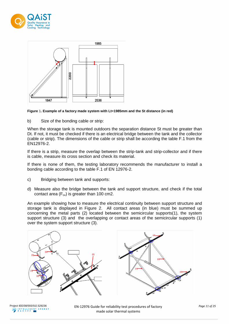
The tank length (Lt) and St separation distance (distance between collector and tank) must be measured and then calculate the minimum separation distance (Dt) which is the product Lt x 0,044.
Project IEE/08/593/SI2.529236
EN-12976 Guide for reliability test procedures of factory
made solar thermal systems
Page 11 of 25
Figure 1. Example of a factory made system with Lt=1985mm and the St distance (in red)
b) Size of the bonding cable or strip:
When the storage tank is mounted outdoors the separation distance St must be greater than Dt. If not, it must be checked if there is an electrical bridge between the tank and the collector (cable or strip). The dimensions of the cable or strip shall be according the table F.1 from the EN12976-2.
If there is a strip, measure the overlap between the strip-tank and strip-collector and if there is cable, measure its cross section and check its material.
If there is none of them, the testing laboratory recommends the manufacturer to install a bonding cable according to the table F.1 of EN 12976-2.
c) Bridging between tank and supports:
d) Measure also the bridge between the tank and support structure, and check if the total contact area (Fov) is greater than 100 cm2.
An example showing how to measure the electrical continuity between support structure and storage tank is displayed in Figure 2. All contact areas (in blue) must be summed up concerning the metal parts (2) located between the semicircular supports(1), the system support structure (3) and the overlapping or contact areas of the semicircular supports (1) over the system support structure (3).
Project IEE/08/593/SI2.529236
EN-12976 Guide for reliability test procedures of factory
made solar thermal systems
Page 12 of 25
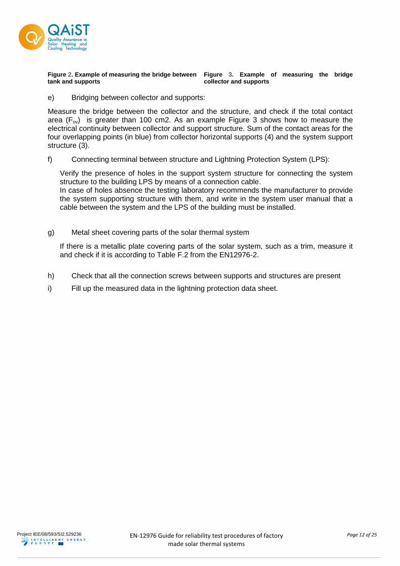
Figure 2. Example of measuring the bridge between tank and supports
Figure 3. Example of measuring the bridge collector and supports
e) Bridging between collector and supports:
Measure the bridge between the collector and the structure, and check if the total contact area (Fov) is greater than 100 cm2. As an example Figure 3 shows how to measure the electrical continuity between collector and support structure. Sum of the contact areas for the four overlapping points (in blue) from collector horizontal supports (4) and the system support structure (3).
f) Connecting terminal between structure and Lightning Protection System (LPS):
Verify the presence of holes in the support system structure for connecting the system structure to the building LPS by means of a connection cable. In case of holes absence the testing laboratory recommends the manufacturer to provide the system supporting structure with them, and write in the system user manual that a cable between the system and the LPS of the building must be installed.
g) Metal sheet covering parts of the solar thermal system
If there is a metallic plate covering parts of the solar system, such as a trim, measure it and check if it is according to Table F.2 from the EN12976-2.
h) Check that all the connection screws between supports and structures are present
i) Fill up the measured data in the lightning protection data sheet.
Project IEE/08/593/SI2.529236
EN-12976 Guide for reliability test procedures of factory
made solar thermal systems
Page 13 of 25
5.6 Safety Equipment
Safety valves
The system shall be checked according to 5.6.1 of EN 12976-2.
The safety valves shall conform to EN 1489. (The manufacturers shall deliver these documents. The test laboratory shall check, if the safety valves delivered with the test sample fit to the documents.)
Check the system documentation to verify that each collector circuit or group of collector circuits is fitted with at least one safety valve.
Check the specification of the safety valves, whether the materials conform to:
- resist the temperature conditions which it is exposed to, especially the highest temperature that can occur.
- resist the heat transfer medium.
Check whether the size of the safety valve is correct in order that it can release highest flow of hot water or steam that can occur. The dimension of the safety valve(s) shall be proved by suitable means (Nominal diameter of the valve outlet must be at least equal to inlet diameter).
Check whether the temperature of the heat transfer medium at the release pressure of the safety valve exceeds the maximum allowed temperature of the heat transfer medium.
Safety lines and expansion lines
The system shall be checked according to 5.6.2 of EN 12976-2.
Check the system documentation to verify that safety and expansion lines, if any present, cannot be shut-off.
Check the internal diameter of the expansion line, if any present, to verify if, for the highest flow of hot water or steam that can occur, at no place in the collector loop the maximum allowed pressure is exceeded due to the pressure drop in these lines. The dimension of the safety line and expansion line shall be proved by suitable means.
Check the system documentation to verify that the expansion line and the safety line, if any present, are connected and laid in such a way that any accumulation of dirt, scale or similar impurities are avoided.
Blow-off lines
The system shall be checked according to 5.6.3 of EN 12976-2.
Check the hydraulic scheme and system documentation to verify that the blow-off lines, if any present, cannot freeze up and that no water can accumulate within these lines. The orifices of the blow-off lines shall be arranged in such a way that any steam or heat transfer medium issuing from the safety valves does not cause any risk for people, materials or environment.
Project IEE/08/593/SI2.529236
EN-12976 Guide for reliability test procedures of factory
made solar thermal systems
Page 14 of 25
5.7 Labeling
The testing laboratory should check that the manufacturer provides all information required by EN12976-1 on the marking plate or label.
The label should be included in the documentation of the system.
Even though the collector or the storage tank can have separate labels for their technical characteristics, the information required for the complete system should be placed on one template. The manufacturer can combine those templates, ensuring though that the information for the specific type of the system is available on the marking.
It is recommended the consultation of checklists for evaluation of system documentation available as Solar Keymark Document SKN N0157R01
5.8 Reverse flow protection
The purpose of this test is to observe if there is reverse flow in the collector loop of the solar thermal system. A visual inspection shall be performed on the existence of a check valve or other reverse flow provisions (like for example constructional solutions). If such provisions exist, the procedure described below is not mandatory
In the case of thermosiphon systems, usually check valve do not exist. To view the need for a check valve, it is necessary to do the test in section 7.8 “Determination of the storage tank heat losses” of ISO 9459-2. The test should be performed twice, one time with the collector loop connected and one time with the collector loop disconnected (i.e. with no flow in the collector loop).
In case the measured heat loss coefficient with the collector loop connected is greater than the one with the collector loop disconnected, this implies potential presence of reverse flow. A difference between the heat loss coefficients in the range of 15 % is considered as an indication for the presence of reverse flow. The existence of a check valve or another obviation against reverse flow becomes necessary.
5.9 Electrical safety
The required electrical safety test within EN 12976-2 is a document examination for all electrical components used in the system. The European Low Voltage Directive (LVD) 2006/95/EC is the basic document for all kind of electrical safety issues within a solar thermal system.
Within the LVD it is written:
For electrical equipment within its scope, the Directive covers all health and safety risks, thus ensuring that electrical equipment is safe in its intended use.
As well as:
The "Low Voltage" Directive is a "total" harmonization directive in the sense that
it has superseded existing national regulations in the field covered: electrical equipment may only be put on the market if it is in conformity with the
1 (http://www.estif.org/solarkeymark/Links/Internal_links/network/sknwebdoclist/SKN_N0157R0.pdf)
Project IEE/08/593/SI2.529236
EN-12976 Guide for reliability test procedures of factory
made solar thermal systems
Page 15 of 25
requirements of the Directive and, on the other hand, Member States may not impede free circulation or the marketing of conforming equipment.
In general, solar thermal test labs did not cover the scope of LVD, so for every electrical component used within the system, a conformity declaration given by an accredited independent test laboratory need to be available.
Examples for electrical components within a solar thermal system and within the scope of the LVD are:
- Electrical pumps
- Electrical valves
- Controller
- Electrical Auxiliary heater
Project IEE/08/593/SI2.529236
EN-12976 Guide for reliability test procedures of factory
made solar thermal systems
Page 16 of 25
6 Additional required collector reliability tests according to EN 12975-1
This chapter is only applicable on systems with none separable collectors.
For systems with separable collectors, deliverable D2.2 – A guideline to the standard EN 12975, could be used as guide for test Laboratories and Manufacturers on applicable tests.
6.1 High temperature resistance
Systems with non-separable collectors, e.g. integrated collector storage (ICS) systems, have to be tested according to EN 12975-2, 5.3. with empty storage tank and heat exchangers. In some cases the system would be destroyed by this test, because it’s only designed to withstand maximum temperatures of the filled system, connected to the mains water supply. In this case the test has to be performed at the filled system:
- Place temperature sensors at a suitable place, which represents (in all likelihood) the highest temperature within the system (clearly describe it in the test results) and at the system outlet.
- Perform the test according to EN 12975-2, 5.3
- After finishing the test, perform a conditioning of the system to determine the maximum system temperature and the maximum draw-off temperature for the test report. It is recommended to use cold water (less than 25 °C) with at least 10 l/min (or the maximum design flow rate). At least one storage volume shall be withdrawn. This part of test is intended to assess the capability of the system to withstand such thermal shocks without failure.
- Check the pass criteria according to EN 12975-1, 5.3.1
- Verify the documentation, labeling and system parts: It has to be clearly stated in the documents for the installer/user and on the label, that the system is not able to withstand stagnation conditions with empty storage tank and that it has to be continuously connected to the mains water supply. The manufacturer has to deliver a cover to protect the system from solar irradiation during installation. It shall be described in the manual how to handle this cover until connection to the mains water supply and filling of the system.
Most common problems leading to major failure are:
- Breaking of cover or vacuum loss
- Absorber leakage or such deformation that permanent contact between absorber and
cover is established
- Deformation of cover or cover fixing
Project IEE/08/593/SI2.529236
EN-12976 Guide for reliability test procedures of factory
made solar thermal systems
Page 17 of 25
6.2 Exposure test
According to the existing standard EN 12976-1, exposure test is only required for separable collectors. In contrast to that, it will be recommended to follow the following procedure.
The exposure test according to EN 12975-2. 5.4 has not to be performed on the condition that the installation manual for the system specifies that the empty system shall be protected against prolonged exposure of solar radiation.
The documentation has to be checked - if the manufacturer declares the empty system to be safe without protection, the test has to be performed.
6.3 External thermal shock test
Systems with non-separable collectors, e.g. integrated collector storage (ICS) systems, have to be tested according to EN 12975-2, 5.5. with empty storage tank and heat exchangers.
The water spray shall be applied according to the EN 12975-2,5.7 “Rain penetration test” on the complete surface of the system. The minimum flow rate of 0.02 kg/s per m² shall take the aperture area and the projected area of the storage tank into account.
In some cases the system would be destroyed by this test, because it’s only designed to withstand maximum temperatures of the filled system, connected to the mains water supply. In this case the test has to be performed at the filled system:
- Place temperature sensors at a suitable place, which represents (in all likelihood) the highest temperature within the system (clearly describe it in the test results) and at the system outlet.
- Perform the test according to EN 12975-5, 5.5 with above mentioned requirements for empty systems
- Check the pass criteria according to EN 12975-1, 5.3
- Verify the documentation, labeling and system parts: It has to be clearly stated in the documents for the installer/user and on the label, that the system is not able to withstand stagnation conditions with empty storage tank and that it has to be continuously connected to the mains water supply. The manufacturer has to deliver a cover to protect the system from solar irradiation during installation. It shall be described in the manual how to handle this cover until connection to the mains water supply and filling of the system.
Most common problems leading to major failure are:
- Accumulation of humidity (shall completely disappear within 4 hours of solar irradiation above 800 W/m²)
- Breaking of cover or vacuum loss
Project IEE/08/593/SI2.529236
EN-12976 Guide for reliability test procedures of factory
made solar thermal systems
Page 18 of 25
6.4 Internal thermal shock test
According to EN 12976-1, 4.3.1 the internal thermal shock test is not required for systems with none-separable collectors.
Nevertheless it is recommended to combine this test with the mandatory high temperature resistance test. The test is at least useful for open loop systems, where components of the empty system may reach high temperatures. It is intended to assess the capability of the system to withstand thermal shocks without failure.
If the internal thermal shock test is performed, the procedure and criteria of EN 12975-2, 5.6 have to be taken into account.
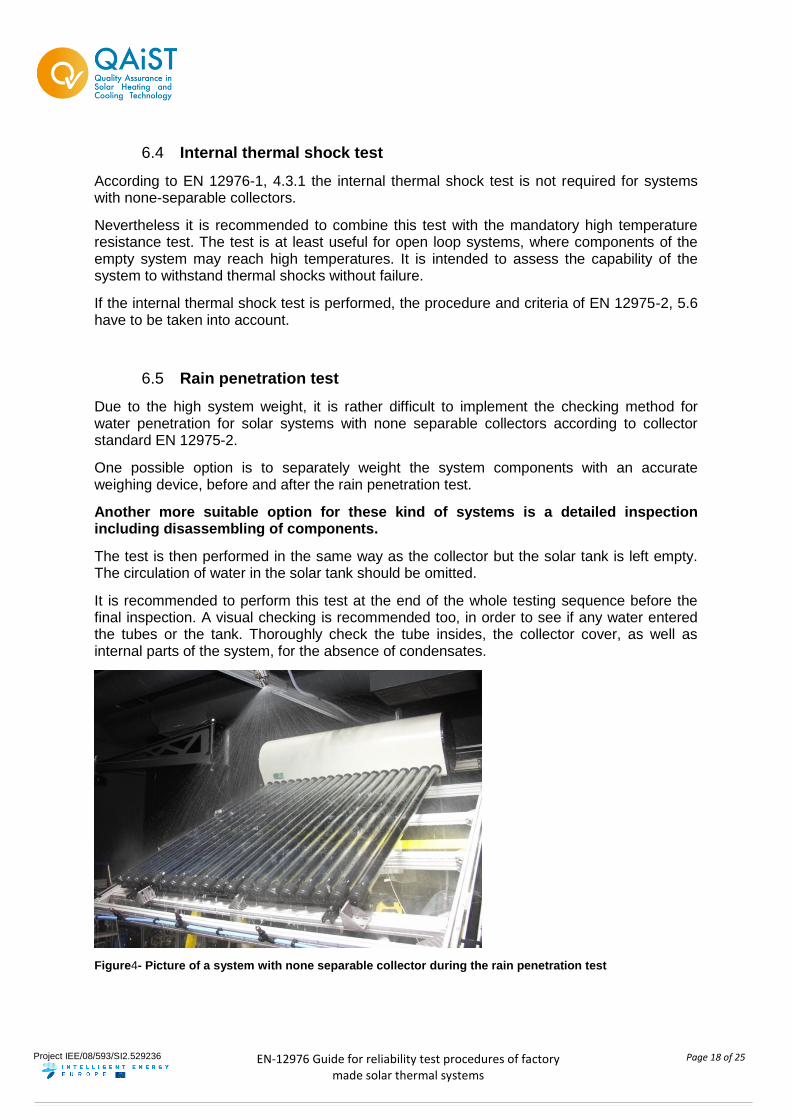
6.5 Rain penetration test
Due to the high system weight, it is rather difficult to implement the checking method for water penetration for solar systems with none separable collectors according to collector standard EN 12975-2.
One possible option is to separately weight the system components with an accurate weighing device, before and after the rain penetration test.
Another more suitable option for these kind of systems is a detailed inspection including disassembling of components.
The test is then performed in the same way as the collector but the solar tank is left empty. The circulation of water in the solar tank should be omitted.
It is recommended to perform this test at the end of the whole testing sequence before the final inspection. A visual checking is recommended too, in order to see if any water entered the tubes or the tank. Thoroughly check the tube insides, the collector cover, as well as internal parts of the system, for the absence of condensates.
Figure4- Picture of a system with none separable collector during the rain penetration test
Project IEE/08/593/SI2.529236
EN-12976 Guide for reliability test procedures of factory
made solar thermal systems
Page 19 of 25
6.6 Mechanical load test
This test is used to evaluate the carrying capacity of a (thermosiphon) system due to snow and wind loads. The following procedure is for systems comprising a rack with a tilt angle where either the collector is separable or not separable from the tank. In both cases it will be recommended that the whole system has to undergo a mechanical load test, not only for systems with not separable collectors as described in EN-12976-1 Chapter 4.3.1. The mechanical load test is adopting the procedure according to EN 12975-2 Chapter 5.9.
Apparatus
plane surface to put the system on
- sand sacks (stone plates,…)
- measuring tape
- stop watch
- camera
- straps for keeping single weights in position
Safety precaution
- safety glasses
- safety shoes
- gloves
- long-sleeved clothing and cap
During the test extreme caution should be exercised at any time since the system may collapse under the weight. Therefore, during the test no other person should stay on or in the immediate vicinity of the test object without proper safety equipment.
Calculation procedure for the mechanical load
The requested pressure on the system is charged with sand sacks (or stone plates) and should be raised in 250 Pa steps until 1000 Pa.
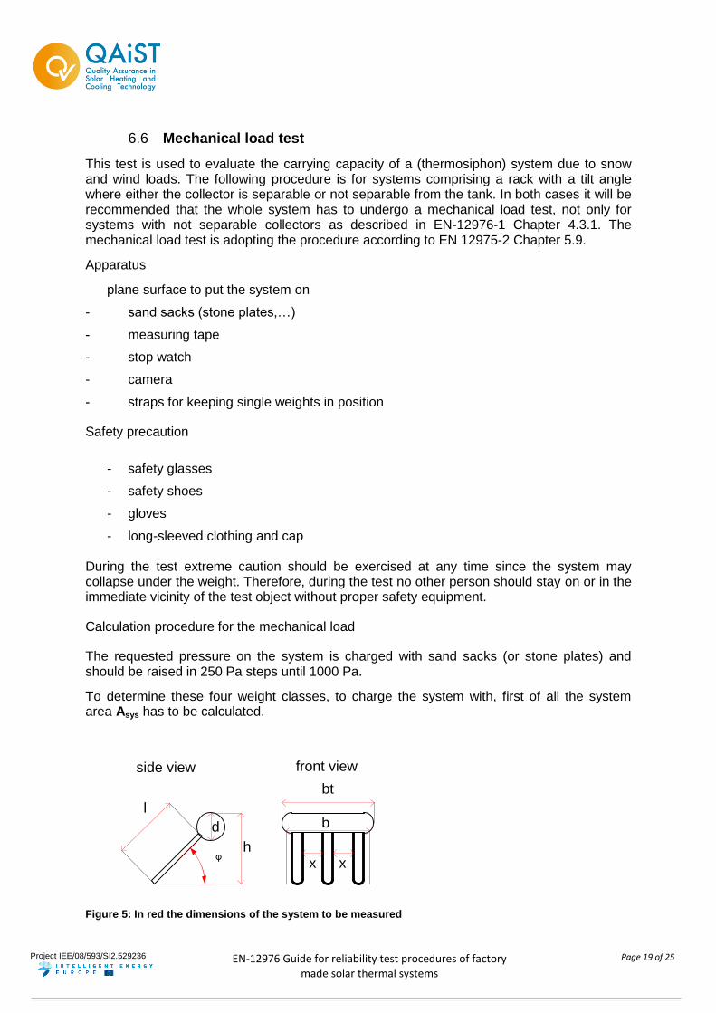
To determine these four weight classes, to charge the system with, first of all the system area Asys has to be calculated.
h
l
x x
bt
side view front view
d b
φ
Figure 5: In red the dimensions of the system to be measured
Project IEE/08/593/SI2.529236
EN-12976 Guide for reliability test procedures of factory
made solar thermal systems
Page 20 of 25
Asys = AT + Abrutt – Ax AT = area tank
bt = width tank
d = diameter
Abrutt = gross collector area
l = length of collector/ length mounting device
b = width collector/ width mounting device
AT = bt *d
Abrutt = l*b
for vacuum tube collectors*:
Ax = l*x*a Ax = tube spacing area
x = distance between tubes
a = number of gaps between tubes
*Note:
In case there is a reflector located behind the tubes, then the tube spacing area Ax is set to zero (Ax =0).
Now the mass m, the system has to be charged with, can be determined with pressure
p = F/A p = [Pa] = N/m² and force
F = m * g F = [N] = kg m /s²
g = acceleration due to gravity = 9,81 m/s²
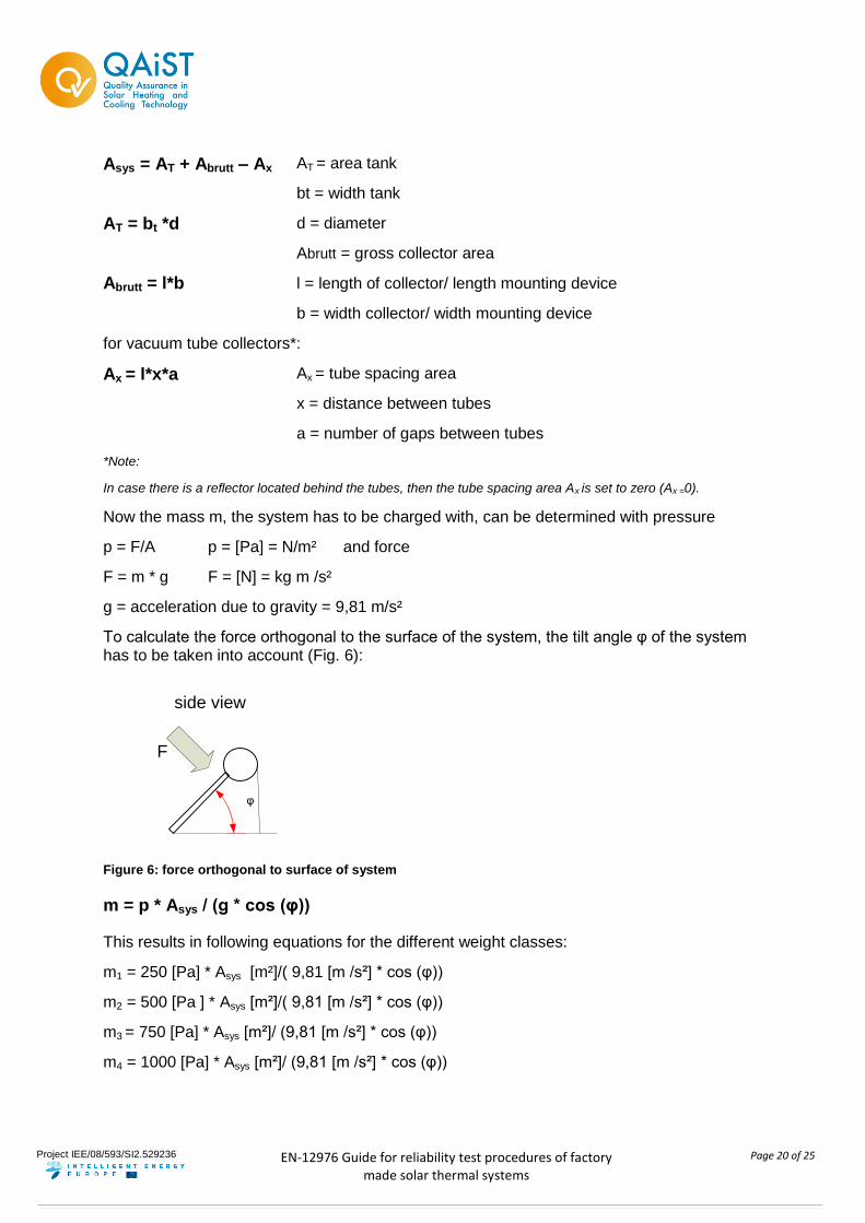
To calculate the force orthogonal to the surface of the system, the tilt angle φ of the system has to be taken into account (Fig. 6):
side view
φ
F
Figure 6: force orthogonal to surface of system
m = p * Asys / (g * cos (φ))
This results in following equations for the different weight classes:
m1 = 250 [Pa] * Asys [m²]/( 9,81 [m /s²] * cos (φ))
m2 = 500 [Pa ] * Asys [m²]/( 9,81 [m /s²] * cos (φ))
m3 = 750 [Pa] * Asys [m²]/ (9,81 [m /s²] * cos (φ))
m4 = 1000 [Pa] * Asys [m²]/ (9,81 [m /s²] * cos (φ))
Project IEE/08/593/SI2.529236
EN-12976 Guide for reliability test procedures of factory
made solar thermal systems
Page 21 of 25
Out of these masses, the number of sand sacks per weight class can be calculated.
The weight of each sand sack has to be checked.
i = m1234/mS I = number of sand sacks
m1234= load to charge the system with
mS = mass of sand sack
Procedure
- The system has to be mounted according to the manufacturer.
- Tank should be filled with water during the test.
- Before testing, the whole system has to be checked for damages on the rack, tank or collector.
- Following steps should be conducted:
a. Calculate the weight load -number of sand sacks- for the 4 steps according to 5.7.4
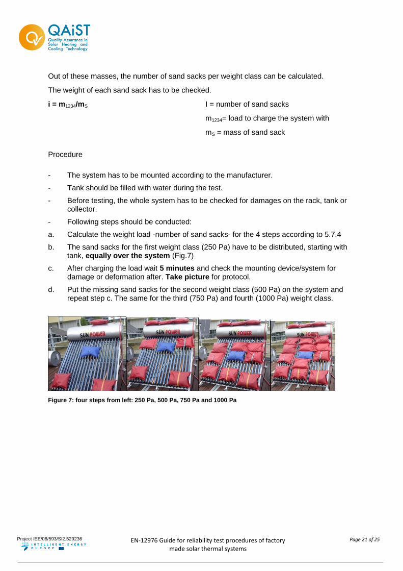
b. The sand sacks for the first weight class (250 Pa) have to be distributed, starting with tank, equally over the system (Fig.7)
c. After charging the load wait 5 minutes and check the mounting device/system for damage or deformation after. Take picture for protocol.
d. Put the missing sand sacks for the second weight class (500 Pa) on the system and repeat step c. The same for the third (750 Pa) and fourth (1000 Pa) weight class.
Figure 7: four steps from left: 250 Pa, 500 Pa, 750 Pa and 1000 Pa
Project IEE/08/593/SI2.529236
EN-12976 Guide for reliability test procedures of factory
made solar thermal systems
Page 22 of 25
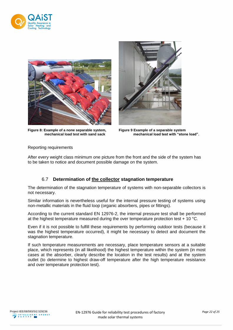
Figure 8: Example of a none separable system, mechanical load test with sand sack
Figure 9 Example of a separable system mechanical load test with “stone load”.
Reporting requirements
After every weight class minimum one picture from the front and the side of the system has to be taken to notice and document possible damage on the system.
6.7 Determination of the collector stagnation temperature
The determination of the stagnation temperature of systems with non-separable collectors is not necessary.
Similar information is nevertheless useful for the internal pressure testing of systems using non-metallic materials in the fluid loop (organic absorbers, pipes or fittings).
According to the current standard EN 12976-2, the internal pressure test shall be performed at the highest temperature measured during the over temperature protection test + 10 °C.
Even if it is not possible to fulfill these requirements by performing outdoor tests (because it was the highest temperature occurred), it might be necessary to detect and document the stagnation temperature.
If such temperature measurements are necessary, place temperature sensors at a suitable place, which represents (in all likelihood) the highest temperature within the system (in most cases at the absorber, clearly describe the location in the test results) and at the system outlet (to determine to highest draw-off temperature after the high temperature resistance and over temperature protection test).
Project IEE/08/593/SI2.529236
EN-12976 Guide for reliability test procedures of factory
made solar thermal systems
Page 23 of 25
6.8 Final Inspection of the collector components
For the final inspection, all requirements as described in “Guide for EN 12975” need to be fulfilled. In addition to that, some parts of the tank could be part of the collector.
For tank integrated condenser tubes for heat pipes, e.g. the tank is also the manifold of the collector and need to be inspected according to burning, shrinking etc..
Further investigations during final inspection like inner tank inspection and tank insulation inspection need to be implemented into EN 12976-2 and are not related to the collector part of the system.
Of course it will be recommended to inspect the internal surface of the tanks by using a digital camera though the electrical auxiliary heater opening or by using an endoscope camera.
A strict assessment on the insulation (water ingress) should also be implemented into EN 12976-2 and not only be used for none separable collector tanks.
Project IEE/08/593/SI2.529236
EN-12976 Guide for reliability test procedures of factory
made solar thermal systems
Page 24 of 25
7 System and component requirements according to EN 12976-1
In this chapter, all requirements mentioned in EN 12976-1 but without a test in EN 12976-2 should be described for manufacturer and laboratories.
7.1 Suitable for drinking water
The standard states that a Factory Made System shall conform to EN 806-1-Specifications for installations inside buildings conveying water for human consumption. This standard mainly refers to good practice in installation. The documentation to installer and owner shall have reference to the standard EN 806-1 and to the need to identify the national or local regulations.
7.2 Materials
Two aspects have to be taken into consideration:
- Resistance to UV of the parts of the system installed outdoors - the manufacturer shall declare that the system is designed to resist to UV radiation during its expected life time. This declaration can be based on knowledge of material’s characteristics delivered by suppliers;
- Resistance of collector’s loop materials – Conformity with recommendations of ISO/TR 10217 will, at least for present know materials and fluids, give assurance on avoiding internal corrosion.
7.3 Components and pipework
Section 4.3 of EN 12976-1 includes requirements for collectors which were already referred in sections 4.2 and 6. of this Guide.
Section 4.3 of EN 12976-1 also includes requirements for Supporting frame, Piping, Heat Exchangers and Control System.
For supporting frame it is necessary that the manufacturer presents documented static calculation according to EN1993-1-1 (steel) or to prEN1999-1-1 (aluminium) and the maximum values for snow and wind load shall be included in the installer’s manual. It is recommended the consultation of checklists for evaluation of system documentation available as Solar Keymark Document SKN N0157R0 2
For piping recommendations of ISO/TR 10217 should be taken into consideration.
For conformity of pumps with EN 809 and EN 1151 it is recommended that the pump is CE marked and the respective declaration of the manufacturer shall be available to the test laboratory/certification body.
The Manufacturer shall design the system heat exchanger to avoid scaling and give recommendations to the installer/owner on quality of water. Also refer to Solar Keymark Document SKN N0157R02.
2 (http://www.estif.org/solarkeymark/Links/Internal_links/network/sknwebdoclist/SKN_N0157R0.pdf)
Project IEE/08/593/SI2.529236
EN-12976 Guide for reliability test procedures of factory
made solar thermal systems
Page 25 of 25
The control system includes sensors placed on collector and outlet, which subjected to stagnation temperature, shall withstand this temperature without drifting more than 1K. The store sensor shall withstand a maximum temperature of 100ºC without drifting more than 1K. The manufacturer shall deliver to the testing laboratory/certification body the information according to Solar Keymark document SKN0136R0.
7.4 Resistance to external influences
In respect of lightning protection, the system should conform to prEN 61024-1. Documentation to the installer and owner shall have reference to lightning protection. It is recommended the consultation of checklists for evaluation of system documentation available as Solar Keymark Document SKN N0157R0 3 . Refer also to section 5.9 of this guide.
7.5 Documentation
Solar Keymark Document SKN N0157R0 provides a good guideline and should be used for the assessment of the collector and system documentation by all involved parties such as manufacturers, test labs and certifiers.
References
Deliverable D3.1 – Checklists for the reliability requirements of Factory Made Systems / Custom Built Systems
SKN N0157R0 - Guideline for the assessment of the solar collector and solar systems technical documentation. Available at http://www.estif.org/solarkeymark/network.php, (01.03.2012)
SKN0136R0 - Parts list, drawings and specifications, Solar Keymark Systems. Available at http://www.estif.org/solarkeymark/network.php, (01.03.2012)
3 (http://www.estif.org/solarkeymark/Links/Internal_links/network/sknwebdoclist/SKN_N0157R0.pdf)