Embed Size (px)
Citation preview
Report No.: RE170707E03 Page No. 1 / 48 Report Format Verision: 6.1.3
EN 300 328 RF Test Report
Report No.: RE170707E03
Test Model: POP
Received Date: July 08, 2017
Test Date: July 31 to Aug. 11, 2017
Issued Date: Aug. 22, 2017
Applicant: Hon Hai Precision Industry CO., LTD
Address: No.2, Zihyou St., Tucheng City, New Taipei City, 23680, TAIWAN
Issued By: Bureau Veritas Consumer Products Services (H.K.) Ltd., Taoyuan Branch Hsin Chu Laboratory
Lab Address: E-2, No.1, Li Hsin 1st Road, Hsinchu Science Park, Hsinchu City 300, Taiwan R.O.C.
This report is for your exclusive use. Any copying or replication of this report to or for any other person or entity, or use of our name or trademark, is permitted only with our prior written permission. This report sets forth our findings solely with respect to the test samples identified herein. The results set forth in this report are not indicative or representative of the quality or characteristics of the lot from which a test sample was taken or any similar or identical product unless specifically and expressly noted. Our report includes all of the tests requested by you and the results thereof based upon the information that you provided to us. You have 60 days from date of issuance of this report to notify us of any material error or omission caused by our negligence, provided, however, that such notice shall be in writing and shall specifically address the issue you wish to raise. A failure to raise such issue within the prescribed time shall constitute your unqualified acceptance of the completeness of this report, the tests conducted and the correctness of the report contents. Unless specific mention, the uncertainty of measurement has been explicitly taken into account to declare the compliance or non-compliance to the specification. The report must not be used by the client to claim product certification, approval, or endorsement by TAF or any government agencies.
Report No.: RE170707E03 Page No. 2 / 48 Report Format Verision: 6.1.3
Table of Contents Release Control Record .................................................................................................................................... 4
1 Certificate of Conformity ......................................................................................................................... 5
2 Summary of Test Results ........................................................................................................................ 6
2.1 Test Instruments .................................................................................................................................. 7 2.2 Measurement Uncertainty ................................................................................................................. 10 2.3 Maximum Measurement Uncertainty ................................................................................................ 10 2.4 Modification Record .......................................................................................................................... 10
3 General Information ............................................................................................................................... 11
3.1 General Description of EUT ............................................................................................................... 11 3.2 Description of Test Modes ................................................................................................................. 12 3.2.1 Test Mode Applicability and Tested Channel Detail ........................................................................... 13 3.3 Description of Support Units ............................................................................................................. 16 3.3.1 Configuration of System under Test .................................................................................................. 17 3.4 General Description of Applied Standards ........................................................................................ 18
4 Test Procedure and Results .................................................................................................................. 19
4.1 RF Output Power............................................................................................................................... 19 4.1.1 Limits of RF Output Power ................................................................................................................ 19 4.1.2 Test Procedures ................................................................................................................................. 19 4.1.3 Deviation from Test Standard ............................................................................................................ 19 4.1.4 Test Setup .......................................................................................................................................... 19 4.1.5 Test Results ....................................................................................................................................... 20 4.2 Power Spectral Density ..................................................................................................................... 21 4.2.1 Limit of Power Spectral Density ........................................................................................................ 21 4.2.2 Test Procedures ................................................................................................................................. 21 4.2.3 Deviation of Test Standard ................................................................................................................ 21 4.2.4 Test Setup .......................................................................................................................................... 21 4.2.5 Test Results ....................................................................................................................................... 22 4.3 Adaptivity (adaptive equipment using modulations other than FHSS) .............................................. 23 4.3.1 Limit of Adaptive ................................................................................................................................ 23 4.3.2 Test Procedure .................................................................................................................................. 24 4.3.3 Deviation from Test Standard ............................................................................................................ 24 4.3.4 Test Setup Configuration ................................................................................................................... 25 4.3.5 List of Measurements ........................................................................................................................ 26 4.3.6 Interference Threshold Level ............................................................................................................. 27 4.3.7 Test Result ......................................................................................................................................... 28 4.4 Occupied Channel Bandwidth ........................................................................................................... 35 4.4.1 Limit of Occupied Channel Bandwidth .............................................................................................. 35 4.4.2 Test Procedure .................................................................................................................................. 35 4.4.3 Deviation from Test Standard ............................................................................................................ 35 4.4.4 Test Setup .......................................................................................................................................... 35 4.4.5 Test Results ....................................................................................................................................... 36 4.5 Transmitter Unwanted Emissions in the Out-of-band Domain .......................................................... 37 4.5.1 Limits of Transmitter Unwanted Emissions in the Out-of-band Domain ............................................ 37 4.5.2 Test Procedure .................................................................................................................................. 37 4.5.3 Deviation from Test Standard ............................................................................................................ 37 4.5.4 Test Setup .......................................................................................................................................... 37 4.5.5 Test Results ....................................................................................................................................... 38 4.6 Transmitter Spurious Emissions in the spurious domain .................................................................. 39 4.6.1 Limits of Transmitter Spurious Emissions ......................................................................................... 39 4.6.2 Test Procedure .................................................................................................................................. 39 4.6.3 Deviation from Test Standard ............................................................................................................ 39 4.6.4 Test Setup .......................................................................................................................................... 39 4.6.5 Test Results ....................................................................................................................................... 40
Report No.: RE170707E03 Page No. 3 / 48 Report Format Verision: 6.1.3
4.7 Receiver Spurious Emissions ........................................................................................................... 42 4.7.1 Limit of Receiver Spurious Radiation ................................................................................................ 42 4.7.2 Test Procedure .................................................................................................................................. 42 4.7.3 Deviation from Test Standard ............................................................................................................ 42 4.7.4 Test Setup .......................................................................................................................................... 42 4.7.5 Test Results ....................................................................................................................................... 43 4.8 Receiver Blocking.............................................................................................................................. 44 4.8.1 Limit of Receiver Blocking ................................................................................................................. 44 4.8.2 Test Procedure .................................................................................................................................. 45 4.8.3 Deviation from Test Standard ............................................................................................................ 45 4.8.4 Test Setup Configuration ................................................................................................................... 45 4.8.5 Test Results ....................................................................................................................................... 46
5 Photographs of the Test Configuration ................................................................................................. 47
Appendix - Information on the Testing Laboratories ........................................................................................ 48
Report No.: RE170707E03 Page No. 4 / 48 Report Format Verision: 6.1.3
Release Control Record
Issue No. Description Date Issued
RE170707E03 Original release. Aug. 22, 2017
Report No.: RE170707E03 Page No. 5 / 48 Report Format Verision: 6.1.3
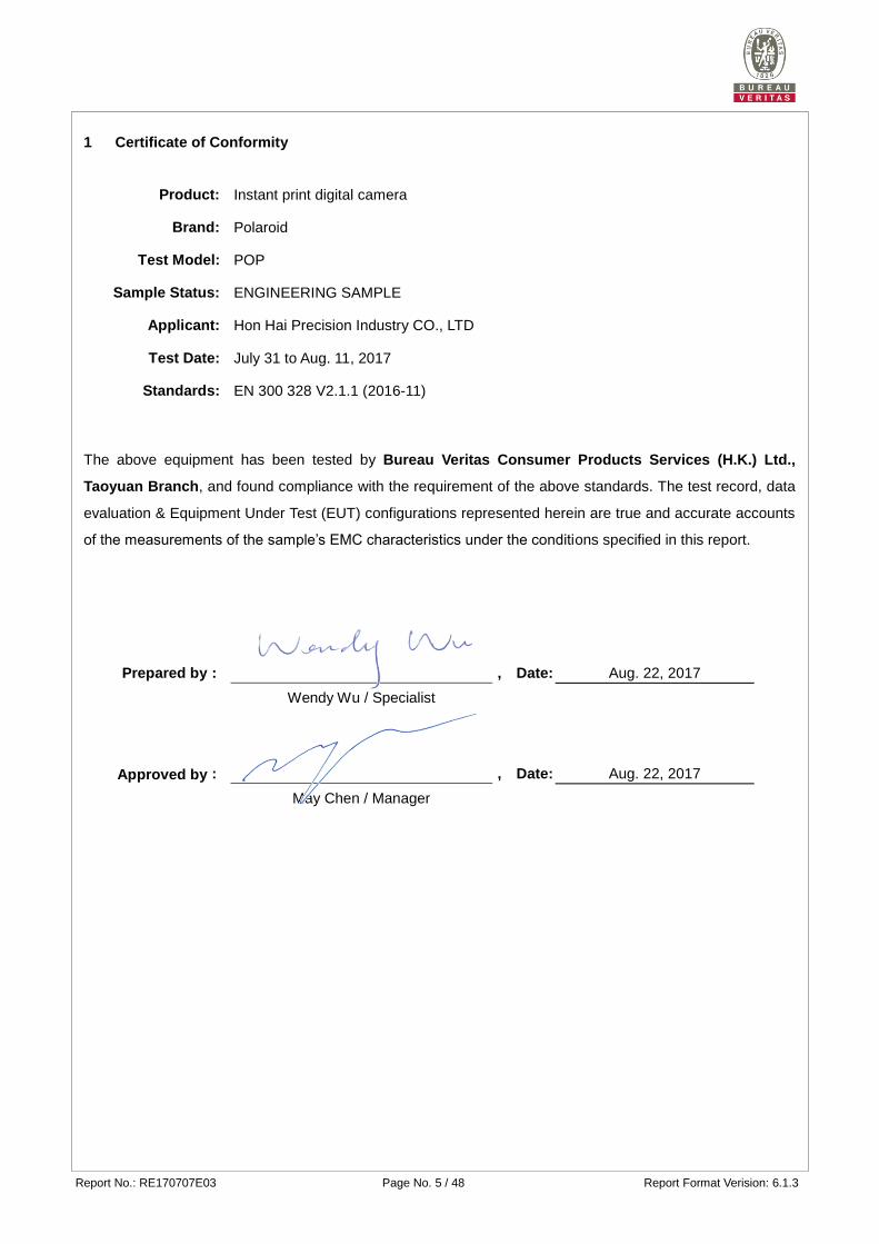
1 Certificate of Conformity
Product: Instant print digital camera
Brand: Polaroid
Test Model: POP
Sample Status: ENGINEERING SAMPLE
Applicant: Hon Hai Precision Industry CO., LTD
Test Date: July 31 to Aug. 11, 2017
Standards: EN 300 328 V2.1.1 (2016-11)
The above equipment has been tested by Bureau Veritas Consumer Products Services (H.K.) Ltd.,
Taoyuan Branch, and found compliance with the requirement of the above standards. The test record, data
evaluation & Equipment Under Test (EUT) configurations represented herein are true and accurate accounts
of the measurements of the sample’s EMC characteristics under the conditions specified in this report.
Prepared by :
, Date: Aug. 22, 2017
Wendy Wu / Specialist
Approved by
:
, Date: Aug. 22, 2017
May Chen / Manager
Report No.: RE170707E03 Page No. 6 / 48 Report Format Verision: 6.1.3
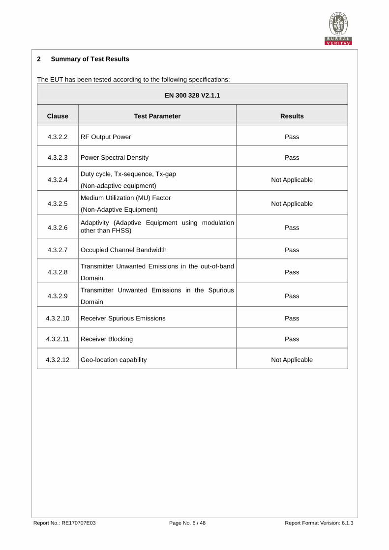
2 Summary of Test Results
The EUT has been tested according to the following specifications:
EN 300 328 V2.1.1
Clause Test Parameter Results
4.3.2.2 RF Output Power Pass
4.3.2.3 Power Spectral Density Pass
4.3.2.4 Duty cycle, Tx-sequence, Tx-gap
(Non-adaptive equipment) Not Applicable
4.3.2.5 Medium Utilization (MU) Factor
(Non-Adaptive Equipment) Not Applicable
4.3.2.6 Adaptivity (Adaptive Equipment using modulation
other than FHSS) Pass
4.3.2.7 Occupied Channel Bandwidth Pass
4.3.2.8 Transmitter Unwanted Emissions in the out-of-band
Domain Pass
4.3.2.9 Transmitter Unwanted Emissions in the Spurious
Domain Pass
4.3.2.10 Receiver Spurious Emissions Pass
4.3.2.11 Receiver Blocking Pass
4.3.2.12 Geo-location capability Not Applicable
Report No.: RE170707E03 Page No. 7 / 48 Report Format Verision: 6.1.3
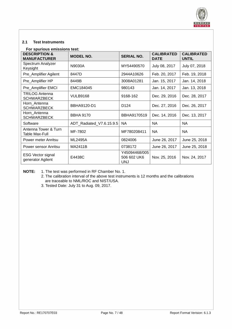
2.1 Test Instruments
For spurious emissions test:
DESCRIPTION &
MANUFACTURER MODEL NO. SERIAL NO.
CALIBRATED
DATE
CALIBRATED
UNTIL
Spectrum Analyzer
Keysight N9030A MY54490570 July 08, 2017 July 07, 2018
Pre_Amplifier Agilent 8447D 2944A10626 Feb. 20, 2017 Feb. 19, 2018
Pre_Amplifier HP 8449B 3008A01281 Jan. 15, 2017 Jan. 14, 2018
Pre_Amplifier EMCI EMC184045 980143 Jan. 14, 2017 Jan. 13, 2018
TRILOG Antenna
SCHWARZBECK VULB9168 9168-162 Dec. 29, 2016 Dec. 28, 2017
Horn_Antenna
SCHWARZBECK BBHA9120-D1 D124 Dec. 27, 2016 Dec. 26, 2017
Horn_Antenna
SCHWARZBECK BBHA 9170 BBHA9170519 Dec. 14, 2016 Dec. 13, 2017
Software ADT_Radiated_V7.6.15.9.5 NA NA NA
Antenna Tower & Turn
Table Max-Full MF-7802 MF780208411 NA NA
Power meter Anritsu ML2495A 0824006 June 26, 2017 June 25, 2018
Power sensor Anritsu MA2411B 0738172 June 26, 2017 June 25, 2018
ESG Vector signal
generator Agilent E4438C
Y45094468/005
506 602 UK6
UNJ
Nov. 25, 2016 Nov. 24, 2017
NOTE: 1. The test was performed in RF Chamber No. 1.
2. The calibration interval of the above test instruments is 12 months and the calibrations
are traceable to NML/ROC and NIST/USA.
3. Tested Date: July 31 to Aug. 09, 2017.
Report No.: RE170707E03 Page No. 8 / 48 Report Format Verision: 6.1.3
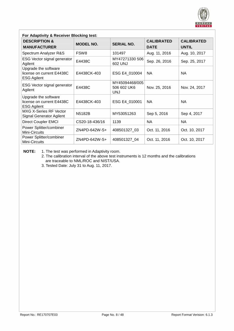
For Adaptivity & Receiver Blocking test:
DESCRIPTION &
MANUFACTURER MODEL NO. SERIAL NO.
CALIBRATED
DATE
CALIBRATED
UNTIL
Spectrum Analyzer R&S FSW8 101497 Aug. 11, 2016 Aug. 10, 2017
ESG Vector signal generator
Agilent E4438C
MY47271330 506
602 UNJ Sep. 26, 2016 Sep. 25, 2017
Upgrade the software
license on current E4438C
ESG Agilent
E4438CK-403 ESG E4_010004 NA NA
ESG Vector signal generator
Agilent E4438C
MY45094468/005
506 602 UK6
UNJ
Nov. 25, 2016 Nov. 24, 2017
Upgrade the software
license on current E4438C
ESG Agilent
E4438CK-403 ESG E4_010001 NA NA
MXG X-Series RF Vector
Signal Generator Agilent N5182B MY53051263 Sep 5, 2016 Sep 4, 2017
Direct Coupler EMCI CS20-18-436/16 1139 NA NA
Power Splitter/combiner
Mini-Circuits ZN4PD-642W-S+ 408501327_03 Oct. 11, 2016 Oct. 10, 2017
Power Splitter/combiner
Mini-Circuits ZN4PD-642W-S+ 408501327_04 Oct. 11, 2016 Oct. 10, 2017
NOTE: 1. The test was performed in Adaptivity room.
2. The calibration interval of the above test instruments is 12 months and the calibrations
are traceable to NML/ROC and NIST/USA.
3. Tested Date: July 31 to Aug. 11, 2017.
Report No.: RE170707E03 Page No. 9 / 48 Report Format Verision: 6.1.3
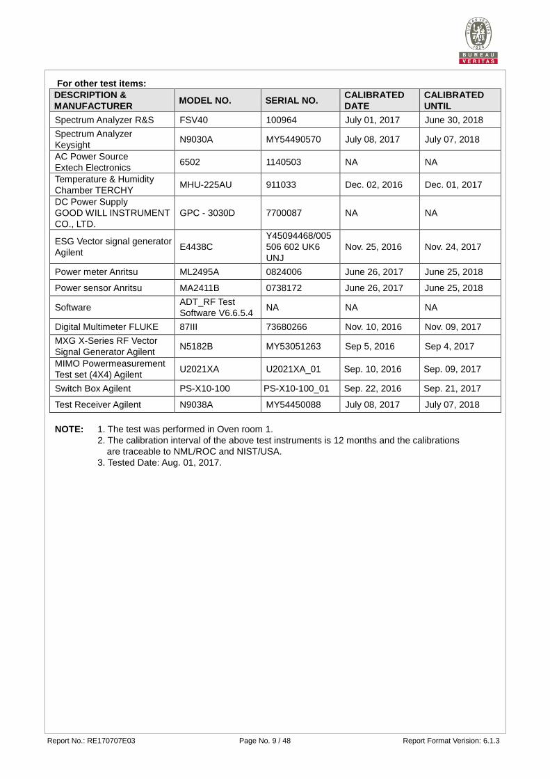
For other test items:
DESCRIPTION &
MANUFACTURER MODEL NO. SERIAL NO.
CALIBRATED
DATE
CALIBRATED
UNTIL
Spectrum Analyzer R&S FSV40 100964 July 01, 2017 June 30, 2018
Spectrum Analyzer
Keysight N9030A MY54490570 July 08, 2017 July 07, 2018
AC Power Source
Extech Electronics 6502 1140503 NA NA
Temperature & Humidity
Chamber TERCHY MHU-225AU 911033 Dec. 02, 2016 Dec. 01, 2017
DC Power Supply
GOOD WILL INSTRUMENT
CO., LTD.
GPC - 3030D 7700087 NA NA
ESG Vector signal generator
Agilent E4438C
Y45094468/005
506 602 UK6
UNJ
Nov. 25, 2016 Nov. 24, 2017
Power meter Anritsu ML2495A 0824006 June 26, 2017 June 25, 2018
Power sensor Anritsu MA2411B 0738172 June 26, 2017 June 25, 2018
Software ADT_RF Test
Software V6.6.5.4 NA NA NA
Digital Multimeter FLUKE 87III 73680266 Nov. 10, 2016 Nov. 09, 2017
MXG X-Series RF Vector
Signal Generator Agilent N5182B MY53051263 Sep 5, 2016 Sep 4, 2017
MIMO Powermeasurement
Test set (4X4) Agilent U2021XA U2021XA_01 Sep. 10, 2016 Sep. 09, 2017
Switch Box Agilent PS-X10-100 PS-X10-100_01 Sep. 22, 2016 Sep. 21, 2017
Test Receiver Agilent N9038A MY54450088 July 08, 2017 July 07, 2018
NOTE: 1. The test was performed in Oven room 1.
2. The calibration interval of the above test instruments is 12 months and the calibrations
are traceable to NML/ROC and NIST/USA.
3. Tested Date: Aug. 01, 2017.
Report No.: RE170707E03 Page No. 10 / 48 Report Format Verision: 6.1.3
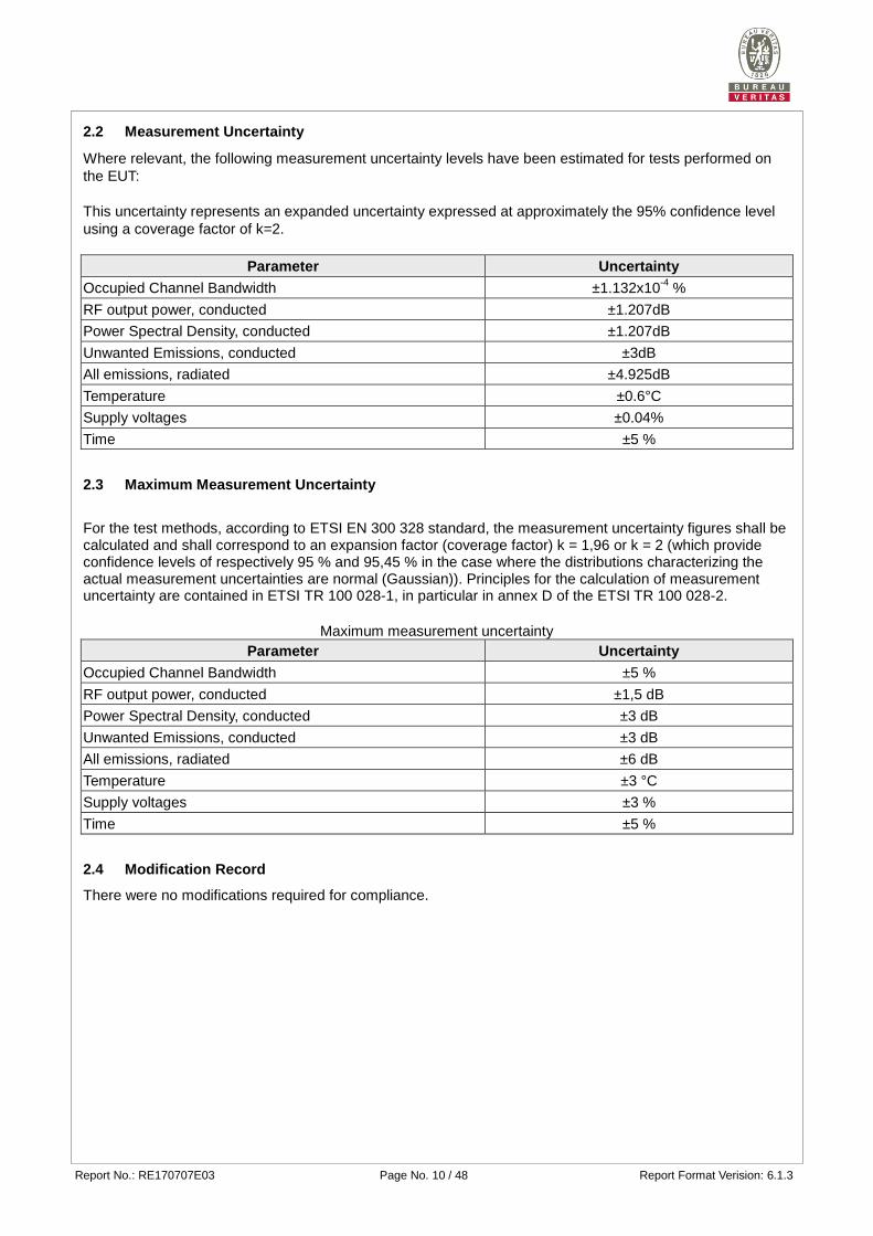
2.2 Measurement Uncertainty
Where relevant, the following measurement uncertainty levels have been estimated for tests performed on
the EUT:
This uncertainty represents an expanded uncertainty expressed at approximately the 95% confidence level
using a coverage factor of k=2.
Parameter Uncertainty
Occupied Channel Bandwidth ±1.132x10⁻⁴
%
RF output power, conducted ±1.207dB
Power Spectral Density, conducted ±1.207dB
Unwanted Emissions, conducted ±3dB
All emissions, radiated ±4.925dB
Temperature ±0.6°C
Supply voltages ±0.04%
Time ±5 %
2.3 Maximum Measurement Uncertainty
For the test methods, according to ETSI EN 300 328 standard, the measurement uncertainty figures shall be calculated and shall correspond to an expansion factor (coverage factor) k = 1,96 or k = 2 (which provide confidence levels of respectively 95 % and 95,45 % in the case where the distributions characterizing the actual measurement uncertainties are normal (Gaussian)). Principles for the calculation of measurement uncertainty are contained in ETSI TR 100 028-1, in particular in annex D of the ETSI TR 100 028-2.
Maximum measurement uncertainty
Parameter Uncertainty
Occupied Channel Bandwidth ±5 %
RF output power, conducted ±1,5 dB
Power Spectral Density, conducted ±3 dB
Unwanted Emissions, conducted ±3 dB
All emissions, radiated ±6 dB
Temperature ±3 °C
Supply voltages ±3 %
Time ±5 %
2.4 Modification Record
There were no modifications required for compliance.
Report No.: RE170707E03 Page No. 11 / 48 Report Format Verision: 6.1.3
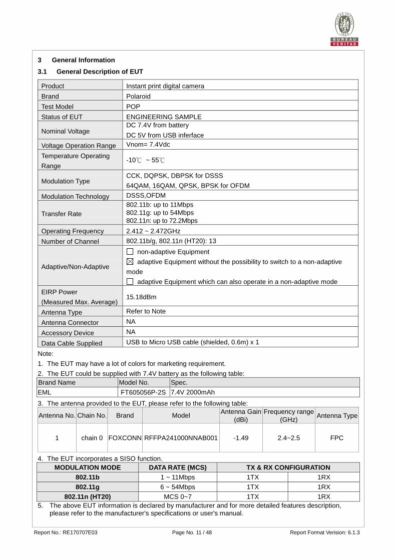
3 General Information
3.1 General Description of EUT
Product Instant print digital camera
Brand Polaroid
Test Model POP
Status of EUT ENGINEERING SAMPLE
Nominal Voltage DC 7.4V from battery
DC 5V from USB inferface
Voltage Operation Range Vnom= 7.4Vdc
Temperature Operating
Range -10℃ ~ 55℃
Modulation Type CCK, DQPSK, DBPSK for DSSS
64QAM, 16QAM, QPSK, BPSK for OFDM
Modulation Technology DSSS,OFDM
Transfer Rate
802.11b: up to 11Mbps
802.11g: up to 54Mbps
802.11n: up to 72.2Mbps
Operating Frequency 2.412 ~ 2.472GHz
Number of Channel 802.11b/g, 802.11n (HT20): 13
Adaptive/Non-Adaptive
non-adaptive Equipment
adaptive Equipment without the possibility to switch to a non-adaptive
mode
adaptive Equipment which can also operate in a non-adaptive mode
EIRP Power
(Measured Max. Average) 15.18dBm
Antenna Type Refer to Note
Antenna Connector NA
Accessory Device NA
Data Cable Supplied USB to Micro USB cable (shielded, 0.6m) x 1
Note:
1. The EUT may have a lot of colors for marketing requirement.
2. The EUT could be supplied with 7.4V battery as the following table:
Brand Name Model No. Spec.
EML FT605056P-2S 7.4V 2000mAh
3. The antenna provided to the EUT, please refer to the following table:
Antenna No. Chain No. Brand Model Antenna Gain
(dBi)
Frequency range
(GHz) Antenna Type
1 chain 0 FOXCONN RFFPA241000NNAB001 -1.49 2.4~2.5 FPC
4. The EUT incorporates a SISO function.
MODULATION MODE DATA RATE (MCS) TX & RX CONFIGURATION
802.11b 1 ~ 11Mbps 1TX 1RX
802.11g 6 ~ 54Mbps 1TX 1RX
802.11n (HT20) MCS 0~7 1TX 1RX
5. The above EUT information is declared by manufacturer and for more detailed features description, please refer to the manufacturer's specifications or user's manual.
Report No.: RE170707E03 Page No. 12 / 48 Report Format Verision: 6.1.3
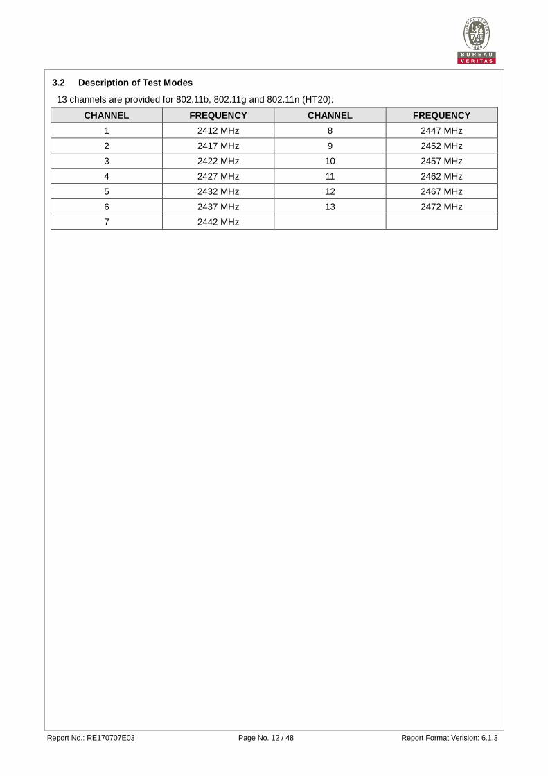
3.2 Description of Test Modes
13 channels are provided for 802.11b, 802.11g and 802.11n (HT20):
CHANNEL FREQUENCY CHANNEL FREQUENCY
1 2412 MHz 8 2447 MHz
2 2417 MHz 9 2452 MHz
3 2422 MHz 10 2457 MHz
4 2427 MHz 11 2462 MHz
5 2432 MHz 12 2467 MHz
6 2437 MHz 13 2472 MHz
7 2442 MHz
Report No.: RE170707E03 Page No. 13 / 48 Report Format Verision: 6.1.3
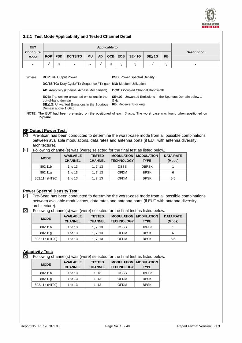
3.2.1 Test Mode Applicability and Tested Channel Detail
EUT
Configure
Mode
Applicable to
Description
ROP PSD DC/TS/TG MU AD OCB EOB SE< 1G SE 1G RB
- √ √ - - √ √ √ √ √ √ -
Where ROP: RF Output Power PSD: Power Spectral Density
DC/TS/TG: Duty Cycle/ Tx-Sequence / Tx-gap MU: Medium Utilization
AD: Adaptivity (Channel Access Mechanism) OCB: Occupied Channel Bandwidth
EOB: Transmitter unwanted emissions in the out-of-band domain
SE<1G: Unwanted Emissions in the Spurious Domain below 1 GHz
SE1G: Unwanted Emissions in the Spurious Domain above 1 GHz
RB: Receiver Blocking
NOTE: The EUT had been pre-tested on the positioned of each 3 axis. The worst case was found when positioned on Z-plane.
RF Output Power Test:
Pre-Scan has been conducted to determine the worst-case mode from all possible combinations
between available modulations, data rates and antenna ports (if EUT with antenna diversity
architecture).
Following channel(s) was (were) selected for the final test as listed below.
MODE AVAILABLE
CHANNEL
TESTED
CHANNEL
MODULATION
TECHNOLOGY
MODULATION
TYPE
DATA RATE
(Mbps)
802.11b 1 to 13 1, 7, 13 DSSS DBPSK 1
802.11g 1 to 13 1, 7, 13 OFDM BPSK 6
802.11n (HT20) 1 to 13 1, 7, 13 OFDM BPSK 6.5
Power Spectral Density Test:
Pre-Scan has been conducted to determine the worst-case mode from all possible combinations
between available modulations, data rates and antenna ports (if EUT with antenna diversity
architecture).
Following channel(s) was (were) selected for the final test as listed below.
MODE AVAILABLE
CHANNEL
TESTED
CHANNEL
MODULATION
TECHNOLOGY
MODULATION
TYPE
DATA RATE
(Mbps)
802.11b 1 to 13 1, 7, 13 DSSS DBPSK 1
802.11g 1 to 13 1, 7, 13 OFDM BPSK 6
802.11n (HT20) 1 to 13 1, 7, 13 OFDM BPSK 6.5
Adaptivity Test:
Following channel(s) was (were) selected for the final test as listed below.
MODE AVAILABLE
CHANNEL
TESTED
CHANNEL
MODULATION
TECHNOLOGY
MODULATION
TYPE
802.11b 1 to 13 1, 13 DSSS DBPSK
802.11g 1 to 13 1, 13 OFDM BPSK
802.11n (HT20) 1 to 13 1, 13 OFDM BPSK
Report No.: RE170707E03 Page No. 14 / 48 Report Format Verision: 6.1.3
Occupied Channel Bandwidth Test:
Pre-Scan has been conducted to determine the worst-case mode from all possible combinations
between available modulations, data rates and antenna ports (if EUT with antenna diversity
architecture).
Following channel(s) was (were) selected for the final test as listed below.
MODE AVAILABLE
CHANNEL
TESTED
CHANNEL
MODULATION
TECHNOLOGY
MODULATION
TYPE
DATA RATE
(Mbps)
802.11b 1 to 13 1, 13 DSSS DBPSK 1
802.11g 1 to 13 1, 13 OFDM BPSK 6
802.11n (HT20) 1 to 13 1, 13 OFDM BPSK 6.5
Transmitter Unwanted Emissions in the Out-of-band Domain Test:
Pre-Scan has been conducted to determine the worst-case mode from all possible combinations
between available modulations, data rates and antenna ports (if EUT with antenna diversity
architecture).
Following channel(s) was (were) selected for the final test as listed below.
MODE AVAILABLE
CHANNEL
TESTED
CHANNEL
MODULATION
TECHNOLOGY
MODULATION
TYPE
DATA RATE
(Mbps)
802.11b 1 to 13 1, 13 DSSS DBPSK 1
802.11g 1 to 13 1, 13 OFDM BPSK 6
802.11n (HT20) 1 to 13 1, 13 OFDM BPSK 6.5
Unwanted Emissions in the Spurious Domain Test (Below 1 GHz):
Pre-Scan has been conducted to determine the worst-case mode from all possible combinations
between available modulations, data rates and antenna ports (if EUT with antenna diversity
architecture).
Following channel(s) was (were) selected for the final test as listed below.
MODE AVAILABLE
CHANNEL
TESTED
CHANNEL
MODULATION
TECHNOLOGY
MODULATION
TYPE
DATA RATE
(Mbps)
802.11n (HT20) 1 to 13 13 OFDM BPSK 6.5
Receiver 1 to 13 13 - - -
Unwanted Emissions in the Spurious Domain Test (above 1 GHz):
Pre-Scan has been conducted to determine the worst-case mode from all possible combinations
between available modulations, data rates and antenna ports (if EUT with antenna diversity
architecture).
Following channel(s) was (were) selected for the final test as listed below.
MODE AVAILABLE
CHANNEL
TESTED
CHANNEL
MODULATION
TECHNOLOGY
MODULATION
TYPE
DATA RATE
(Mbps)
802.11b 1 to 13 1, 13 DSSS DBPSK 1
Receiver 1 to 13 1, 13 - - -
Receiver Blocking test:
Following channel(s) was (were) selected for the final test as listed below.
MODE AVAILABLE
CHANNEL
TESTED
CHANNEL
MODULATION
TECHNOLOGY
MODULATION
TYPE
DATA RATE
(Mbps)
802.11b 1 to 13 1, 13 DSSS DBPSK 1
Report No.: RE170707E03 Page No. 15 / 48 Report Format Verision: 6.1.3
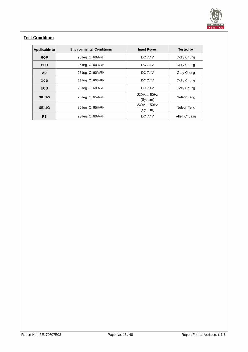
Test Condition:
Applicable to Environmental Conditions Input Power Tested by
ROP 25deg. C, 60%RH DC 7.4V Dolly Chung
PSD 25deg. C, 60%RH DC 7.4V Dolly Chung
AD 25deg. C, 60%RH DC 7.4V Gary Cheng
OCB 25deg. C, 60%RH DC 7.4V Dolly Chung
EOB 25deg. C, 60%RH DC 7.4V Dolly Chung
SE<1G 25deg. C, 65%RH 230Vac, 50Hz
(System) Nelson Teng
SE1G 25deg. C, 65%RH 230Vac, 50Hz
(System) Nelson Teng
RB 23deg. C, 60%RH DC 7.4V Allen Chuang
Report No.: RE170707E03 Page No. 16 / 48 Report Format Verision: 6.1.3
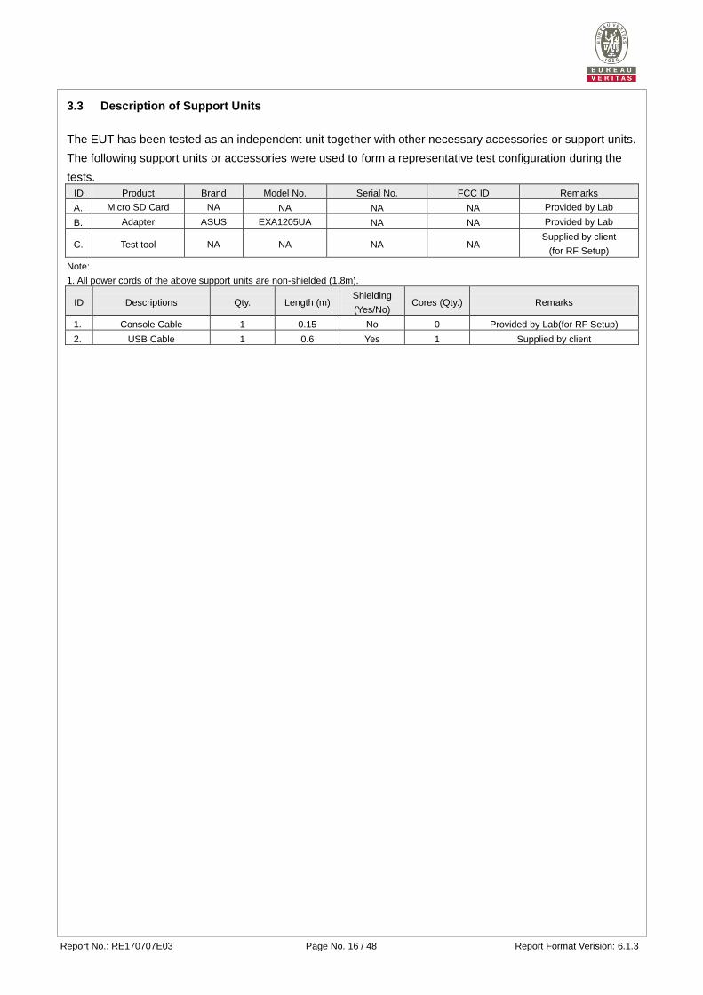
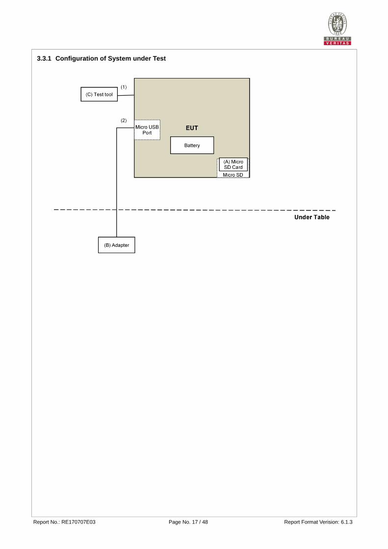
3.3 Description of Support Units
The EUT has been tested as an independent unit together with other necessary accessories or support units.
The following support units or accessories were used to form a representative test configuration during the
tests.
ID Product Brand Model No. Serial No. FCC ID Remarks
A. Micro SD Card NA NA NA NA Provided by Lab
B. Adapter ASUS EXA1205UA NA NA Provided by Lab
C. Test tool NA NA NA NA Supplied by client
(for RF Setup)
Note:
1. All power cords of the above support units are non-shielded (1.8m).
ID Descriptions Qty. Length (m) Shielding
(Yes/No) Cores (Qty.) Remarks
1. Console Cable 1 0.15 No 0 Provided by Lab(for RF Setup)
2. USB Cable 1 0.6 Yes 1 Supplied by client
Note: The core(s) is(are) originally attached to the cable(s).
Report No.: RE170707E03 Page No. 17 / 48 Report Format Verision: 6.1.3
3.3.1 Configuration of System under Test
Report No.: RE170707E03 Page No. 18 / 48 Report Format Verision: 6.1.3
3.4 General Description of Applied Standards
The EUT is a RF Product. According to the specifications of the manufacturer, it must comply with the
requirements of the following standard:
EN 300 328 V2.1.1 (2016-11)
All test items have been performed and recorded as per the above standard.
Report No.: RE170707E03 Page No. 19 / 48 Report Format Verision: 6.1.3
4 Test Procedure and Results
4.1 RF Output Power
4.1.1 Limits of RF Output Power
Condition Frequency Band Limit (e.i.r.p)
Under all test conditions 2400 ~ 2483.5 MHz AV: 20dBm
4.1.2 Test Procedures
Refer to chapter 5.4.2 of EN 300 328 V2.1.1.
Measurement Method
Conducted measurement Radiated measurement
4.1.3 Deviation from Test Standard
No deviation.
4.1.4 Test Setup
The measurements for RF output power was performed at both normal environmental conditions and at the
extremes of the operating temperature. Controlling software (HyperTerminal paste POP camera_Tx
command.txt command) has been activated to set the EUT on specific channel and power level.
Report No.: RE170707E03 Page No. 20 / 48 Report Format Verision: 6.1.3
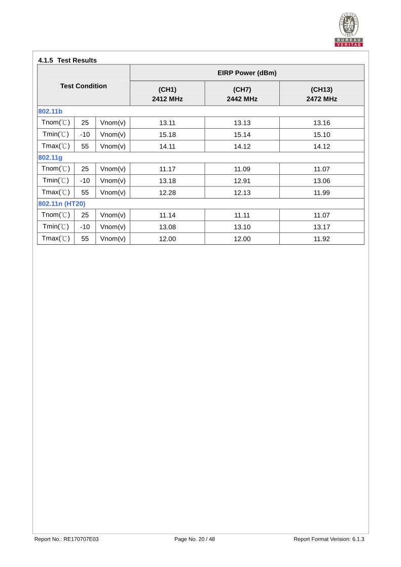
4.1.5 Test Results
Test Condition
EIRP Power (dBm)
(CH1)
2412 MHz
(CH7)
2442 MHz
(CH13)
2472 MHz
802.11b
Tnom(℃) 25 Vnom(v) 13.11 13.13 13.16
Tmin(℃) -10 Vnom(v) 15.18 15.14 15.10
Tmax(℃) 55 Vnom(v) 14.11 14.12 14.12
802.11g
Tnom(℃) 25 Vnom(v) 11.17 11.09 11.07
Tmin(℃) -10 Vnom(v) 13.18 12.91 13.06
Tmax(℃) 55 Vnom(v) 12.28 12.13 11.99
802.11n (HT20)
Tnom(℃) 25 Vnom(v) 11.14 11.11 11.07
Tmin(℃) -10 Vnom(v) 13.08 13.10 13.17
Tmax(℃) 55 Vnom(v) 12.00 12.00 11.92
Report No.: RE170707E03 Page No. 21 / 48 Report Format Verision: 6.1.3
4.2 Power Spectral Density
4.2.1 Limit of Power Spectral Density
Condition Frequency Band Limit (e.i.r.p.)
Under normal conditions 2400 ~ 2483.5 MHz 10dBm / 1MHz
4.2.2 Test Procedures
Refer to chapter 5.4.3 of EN 300 328 V2.1.1.
Measurement Method
Conducted measurement Radiated measurement
Option 1: For equipment with continuous and non-continuous transmissions
Option 2: For equipment with continuous transmission capability or for equipment operating (or with the capability to operate) with a constant duty cycle (e.g. Frame Basedequipment)
4.2.3 Deviation of Test Standard
No deviation.
4.2.4 Test Setup
The test setup has been constructed as the normal test condition. (In case of conducted measurements the
transmitter shall be connected to the measuring equipment via a suitable attenuator.) The power spectral
density as defined in EN 300 328 clause 4.3.2.3 shall be measured and recorded. Controlling software
(HyperTerminal paste POP camera_Tx command.txt command) has been activated to set the EUT on specific
status.
Report No.: RE170707E03 Page No. 22 / 48 Report Format Verision: 6.1.3
4.2.5 Test Results
802.11b
CHANNEL CHANNEL
FREQUENCY (MHz)
Power Density
(dBm/1MHz)
(EIRP)
Limit
(dBm/1MHz)
(EIRP)
PASS/FAIL
1 2412 3.90 10 Pass
7 2442 3.85 10 Pass
13 2472 3.88 10 Pass
802.11g
CHANNEL CHANNEL
FREQUENCY (MHz)
Power Density
(dBm/1MHz)
(EIRP)
Limit
(dBm/1MHz)
(EIRP)
PASS/FAIL
1 2412 -1.12 10 Pass
7 2442 -1.14 10 Pass
13 2472 -1.21 10 Pass
802.11n (HT20)
CHANNEL CHANNEL
FREQUENCY (MHz)
PPower Density
(dBm/1MHz)
(EIRP)
Limit
(dBm/1MHz)
(EIRP)
PASS/FAIL
1 2412 -1.29 10 Pass
7 2442 -1.46 10 Pass
13 2472 -1.56 10 Pass
Report No.: RE170707E03 Page No. 23 / 48 Report Format Verision: 6.1.3
4.3 Adaptivity (adaptive equipment using modulations other than FHSS)
This requirement does not apply to non-adaptive equipment or adaptive equipment operating in a
non-adaptive mode providing the equipment complies with the requirements and/or restrictions applicable to
non-adaptive equipment.
In addition, this requirement does not apply for equipment with a maximum declared RF Output power level of
less than 10 dBm e.i.r.p. or for equipment when operating in a mode where the RF Output power is less than
10 dBm e.i.r.p.
4.3.1 Limit of Adaptive
Applicability of adaptive requirements and limit for wide band modulation techniquesInterference threshold level
Requirement
Operational Mode
Non-LBT
based
Detect and
Avoid
LBT based Detect and Avoid
Frame Based Equipment
Load Based Equipment
(Base on 'Spectrum
Sharing' mechanisms)
Load Based Equipment
(Not using any of the
mechanisms referenced)
Minimum Clear Channel Assessment (CCA) Time
NA 18 us (see note 1) (see note 2) 18 us (see note 1)
Maximum Channel Occupancy (COT) Time
40 ms 1 ms to 10 ms (see note 2) 13ms
Minimum Idle Period 5us 5% of COT (see note 2) 18us (see note 3)
Extended CCA check NA NA (see note 2) 18us~160us
Short Control Signalling Transmissions
Maximum duty cycle of 10 % within an observation period of 50 ms (see note 4)
NOTE 1: The CCA time used by the equipment shall be declared by the supplier. NOTE 2:Load Based Equipment may implement an LBT based spectrum sharing mechanism based on the Clear
ChannelAssessment (CCA) mode using energy detect, as described in IEEE 802.11™-2012 clause 9, clause 10, clause 16,clause 17, clause 19 and clause 20, or in IEEE 802.15.4™-2011 [i.4], clause 4, clause 5 and clause 8
NOTE 3: The Idle Period in between transmissions is considered to be the CCA or the Extended CCA check as there are no transmissions during this period.
NOTE 4: Adaptive equipment may or may not have Short Control Signalling Transmissions
Threshold Level for LBT based Detect and Avoid (Load Based Equipment)
Maximum transmit power (PH) EIRP dBm
Threshold level (TL) (see notes 1 and 2)
20 -70 dBm / MHz
NOTE 1: For a 20 dBm e.i.r.p. transmitter the CCA threshold level (TL) shall be equal to or less than -70 dBm/MHz at the input to the receiver assuming a 0 dBi (receive) antenna assembly. This threshold level (TL) may be corrected for the (receive) antenna assembly gain (G)
NOTE 2: For power levels less than 20 dBm e.i.r.p. the CCA threshold level may be relaxed to: TL = -70 dBm/MHz + 10 × log10 (100 mW / Pout) ; (Pout in mW e.i.r.p.)
Report No.: RE170707E03 Page No. 24 / 48 Report Format Verision: 6.1.3
Unwanted signal parameters for LBT based Detect and Avoid (Load Based Equipment) Wanted signal mean power from
companion device Unwanted signal frequency
(MHz) Unwanted signal power (dBm)
sufficient to maintain the link (see note 2)
2 395 or 2 488,5 (see note 1)
-35 (see note 3)
NOTE 1: The highest frequency shall be used for testing operating channels within the range 2 400 MHz to 2 442 MHz, while the lowest frequency shall be used for testing operating channels within the range 2 442 MHz to 2 483,5 MHz. See clause 5.4.6.1.
NOTE 2: A typical value which can be used in most cases is -50 dBm/MHz. NOTE 3: The level specified is the level in front of the UUT antenna. In case of conducted measurements,
this level has to be corrected by the actual antenna assembly gain.
4.3.2 Test Procedure
Refer to chapter 5.4.6 of EN 300 328 V2.1.1.
Measurement Method
Conducted measurement Radiated measurement
4.3.3 Deviation from Test Standard
No deviation.
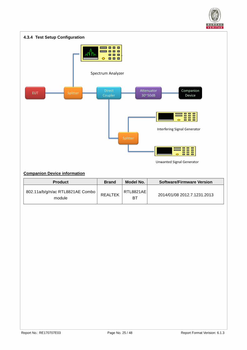
Report No.: RE170707E03 Page No. 25 / 48 Report Format Verision: 6.1.3
4.3.4 Test Setup Configuration
Companion Device information
Product Brand Model No. Software/Firmware Version
802.11a/b/g/n/ac RTL8821AE Combo
module REALTEK
RTL8821AE
BT 2014/01/08 2012.7.1231.2013
Report No.: RE170707E03 Page No. 26 / 48 Report Format Verision: 6.1.3
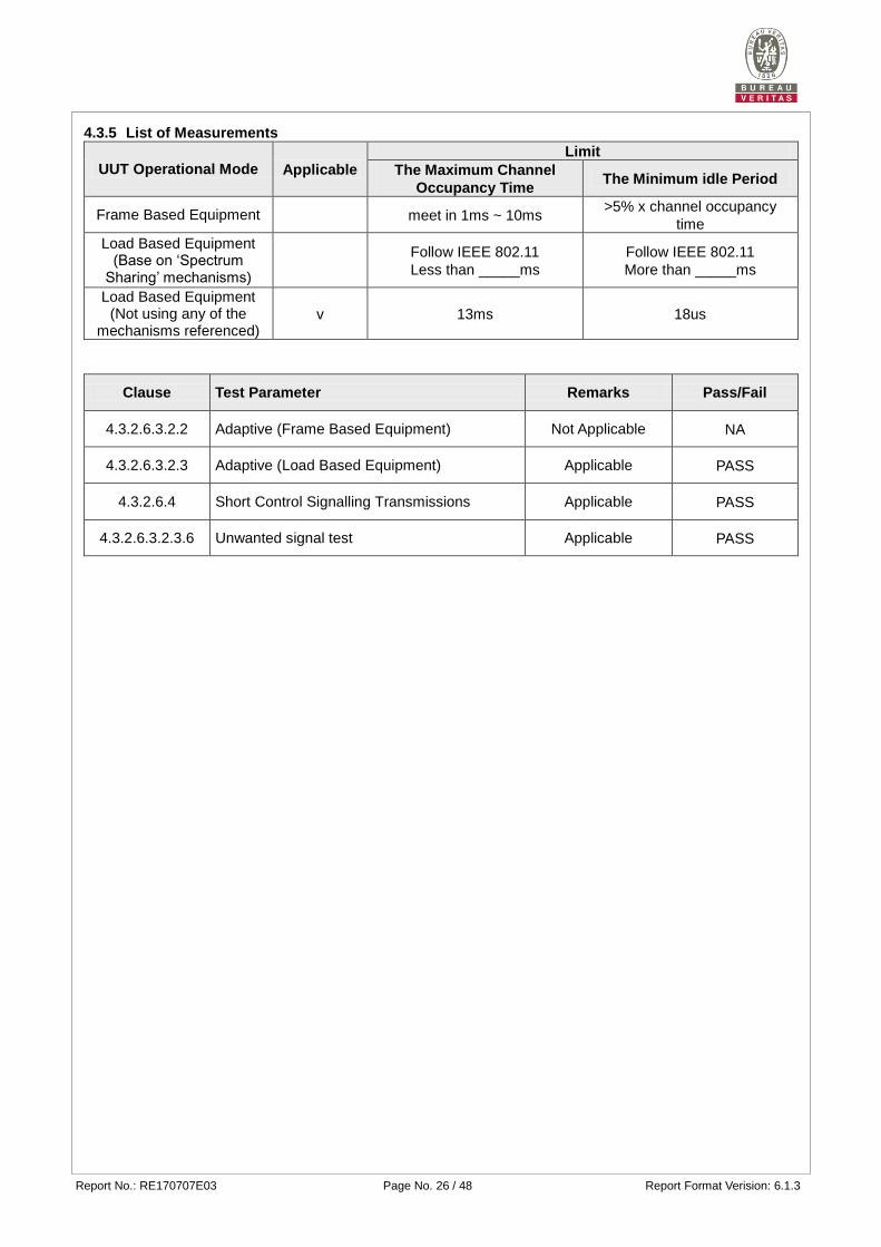
4.3.5 List of Measurements
UUT Operational Mode Applicable
Limit
The Maximum Channel
Occupancy Time The Minimum idle Period
Frame Based Equipment meet in 1ms ~ 10ms >5% x channel occupancy
time
Load Based Equipment (Base on ‘Spectrum
Sharing’ mechanisms)
Follow IEEE 802.11
Less than _____ms
Follow IEEE 802.11
More than _____ms
Load Based Equipment (Not using any of the
mechanisms referenced) v 13ms 18us
Clause Test Parameter Remarks Pass/Fail
4.3.2.6.3.2.2 Adaptive (Frame Based Equipment) Not Applicable NA
4.3.2.6.3.2.3 Adaptive (Load Based Equipment) Applicable PASS
4.3.2.6.4 Short Control Signalling Transmissions Applicable PASS
4.3.2.6.3.2.3.6 Unwanted signal test Applicable PASS
Report No.: RE170707E03 Page No. 27 / 48 Report Format Verision: 6.1.3
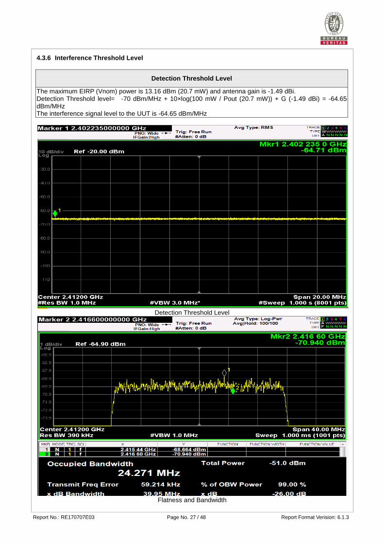
4.3.6 Interference Threshold Level
Detection Threshold Level
The maximum EIRP (Vnom) power is 13.16 dBm (20.7 mW) and antenna gain is -1.49 dBi. Detection Threshold level= -70 dBm/MHz + 10×log(100 mW / Pout (20.7 mW)) + G (-1.49 dBi) = -64.65 dBm/MHz The interference signal level to the UUT is -64.65 dBm/MHz
Detection Threshold Level
Flatness and Bandwidth
Report No.: RE170707E03 Page No. 28 / 48 Report Format Verision: 6.1.3
4.3.7 Test Result
Not applicable to non-adaptive equipment or adaptive equipment operating in a non-adaptive mode
Not applicable to equipment with RF output power is less than 10 dBm e.i.r.p.
Refer to below test result
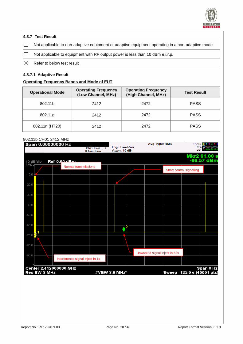
4.3.7.1 Adaptive Result
Operating Frequency Bands and Mode of EUT
Operational Mode Operating Frequency (Low Channel, MHz)
Operating Frequency (High Channel, MHz)
Test Result
802.11b 2412 2472 PASS
802.11g 2412 2472 PASS
802.11n (HT20) 2412 2472 PASS
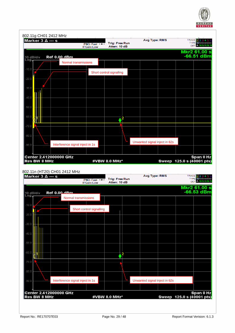
802.11b CH01 2412 MHz
Normal transmissions Short control signalling
Interference signal inject in 1s
Unwanted signal inject in 62s
Report No.: RE170707E03 Page No. 29 / 48 Report Format Verision: 6.1.3
802.11g CH01 2412 MHz
802.11n (HT20) CH01 2412 MHz
Normal transmissions
Short control signalling
Normal transmissions
Short control signalling
Interference signal inject in 1s Unwanted signal inject in 62s
Interference signal inject in 1s Unwanted signal inject in 62s
Report No.: RE170707E03 Page No. 30 / 48 Report Format Verision: 6.1.3
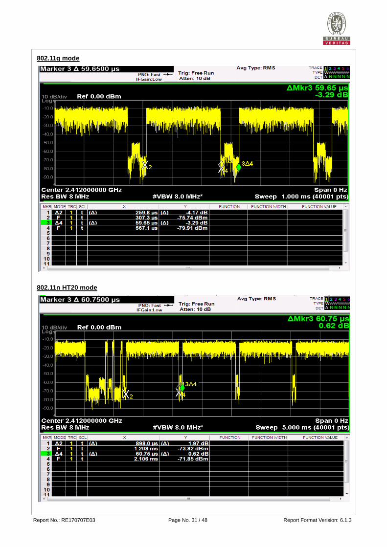
4.3.7.2 The Channel Occupancy Time Result
Operating Frequency Bands and Mode of EUT
Operational Mode
Operating
Frequency
Low Channel
(MHz)
The Channel
Occupancy Time
(ms)
Minimum Idle
Period (ms) Test Result
802.11b 2412 1.33 0.22 PASS
802.11g 2412 0.26 0.06 PASS
802.11n (HT20) 2412 0.90 0.06 PASS
802.11b mode
Report No.: RE170707E03 Page No. 31 / 48 Report Format Verision: 6.1.3
802.11g mode
802.11n HT20 mode
Report No.: RE170707E03 Page No. 32 / 48 Report Format Verision: 6.1.3
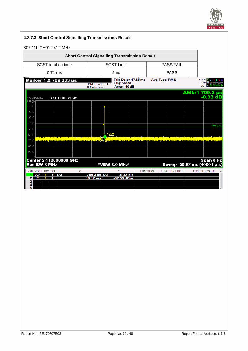
4.3.7.3 Short Control Signalling Transmissions Result
802.11b CH01 2412 MHz
Short Control Signalling Transmission Result
SCST total on time SCST Limit PASS/FAIL
0.71 ms 5ms PASS
Report No.: RE170707E03 Page No. 33 / 48 Report Format Verision: 6.1.3
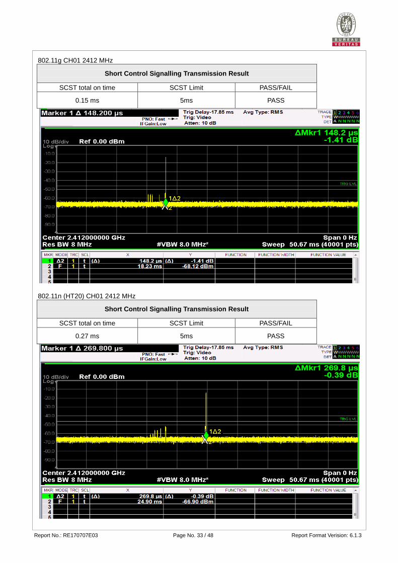
802.11g CH01 2412 MHz
Short Control Signalling Transmission Result
SCST total on time SCST Limit PASS/FAIL
0.15 ms 5ms PASS
802.11n (HT20) CH01 2412 MHz
Short Control Signalling Transmission Result
SCST total on time SCST Limit PASS/FAIL
0.27 ms 5ms PASS
Report No.: RE170707E03 Page No. 34 / 48 Report Format Verision: 6.1.3
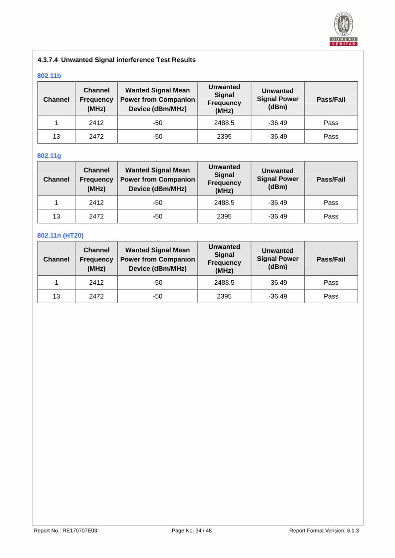
4.3.7.4 Unwanted Signal interference Test Results
802.11b
Channel
Channel
Frequency
(MHz)
Wanted Signal Mean
Power from Companion
Device (dBm/MHz)
Unwanted
Signal
Frequency
(MHz)
Unwanted
Signal Power
(dBm) Pass/Fail
1 2412 -50 2488.5 -36.49 Pass
13 2472 -50 2395 -36.49 Pass
802.11g
Channel
Channel
Frequency
(MHz)
Wanted Signal Mean
Power from Companion
Device (dBm/MHz)
Unwanted
Signal
Frequency
(MHz)
Unwanted
Signal Power
(dBm) Pass/Fail
1 2412 -50 2488.5 -36.49 Pass
13 2472 -50 2395 -36.49 Pass
802.11n (HT20)
Channel
Channel
Frequency
(MHz)
Wanted Signal Mean
Power from Companion
Device (dBm/MHz)
Unwanted
Signal
Frequency
(MHz)
Unwanted
Signal Power
(dBm) Pass/Fail
1 2412 -50 2488.5 -36.49 Pass
13 2472 -50 2395 -36.49 Pass
Report No.: RE170707E03 Page No. 35 / 48 Report Format Verision: 6.1.3
4.4 Occupied Channel Bandwidth
4.4.1 Limit of Occupied Channel Bandwidth
Condition Limit
All types of equipment Shall fall completely within the band
2400 to 2483.5 MHz.
Additional
requirement
For non-adaptive using wide band
modulations other than FHSS system
and e.i.r.p >10dBm.
Less than 20MHz
For non-adaptive Frequency Hopping
system and e.i.r.p >10dBm. Less than 5MHz
4.4.2 Test Procedure
Refer to chapter 5.4.7 of EN 300 328 V2.1.1.
Measurement
Conducted measurement Radiated measurement
4.4.3 Deviation from Test Standard
No deviation.
4.4.4 Test Setup
These measurements only were performed at normal test conditions. The measurement shall be performed
only on the lowest and the highest frequency within the stated frequency range. In case of conducted
measurements the transmitter shall be connected to the measuring equipment via a suitable attenuator.
Controlling software (HyperTerminal paste POP camera_Tx command.txt command) has been activated to
set the EUT on specific status.
Report No.: RE170707E03 Page No. 36 / 48 Report Format Verision: 6.1.3
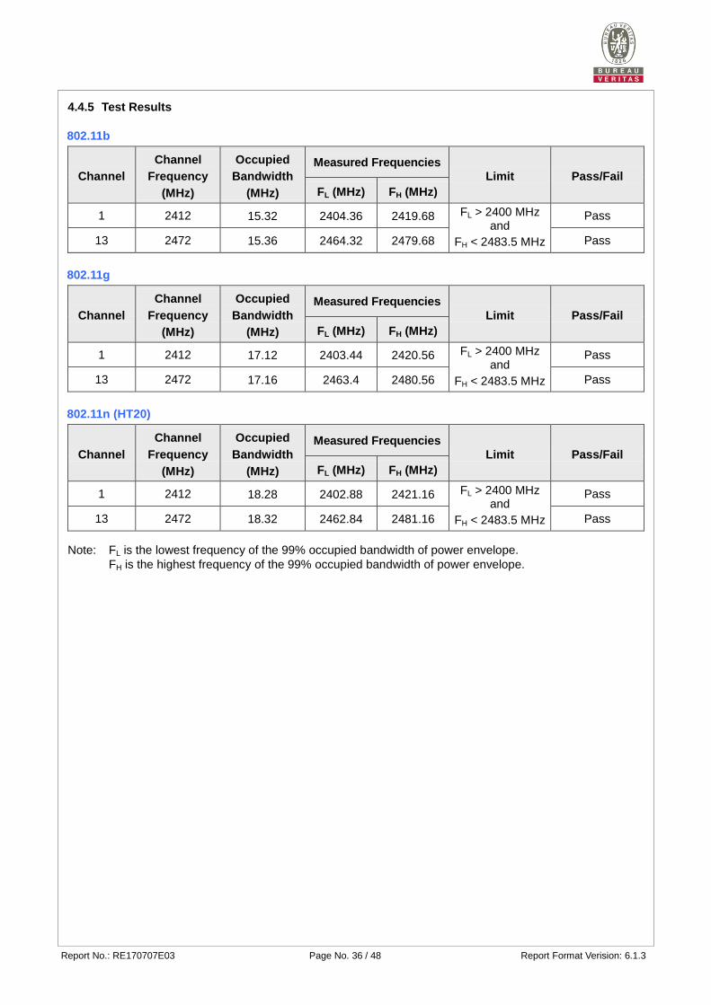
4.4.5 Test Results
802.11b
Channel
Channel
Frequency
(MHz)
Occupied
Bandwidth
(MHz)
Measured Frequencies Limit Pass/Fail
FL (MHz) FH (MHz)
1 2412 15.32 2404.36 2419.68 FL > 2400 MHz and
FH < 2483.5 MHz
Pass
13 2472 15.36 2464.32 2479.68 Pass
802.11g
Channel
Channel
Frequency
(MHz)
Occupied
Bandwidth
(MHz)
Measured Frequencies
Limit Pass/Fail
FL (MHz) FH (MHz)
1 2412 17.12 2403.44 2420.56 FL > 2400 MHz and
FH < 2483.5 MHz
Pass
13 2472 17.16 2463.4 2480.56 Pass
802.11n (HT20)
Channel
Channel
Frequency
(MHz)
Occupied
Bandwidth
(MHz)
Measured Frequencies Limit Pass/Fail
FL (MHz) FH (MHz)
1 2412 18.28 2402.88 2421.16 FL > 2400 MHz and
FH < 2483.5 MHz
Pass
13 2472 18.32 2462.84 2481.16 Pass
Note: FL is the lowest frequency of the 99% occupied bandwidth of power envelope.
FH is the highest frequency of the 99% occupied bandwidth of power envelope.
Report No.: RE170707E03 Page No. 37 / 48 Report Format Verision: 6.1.3
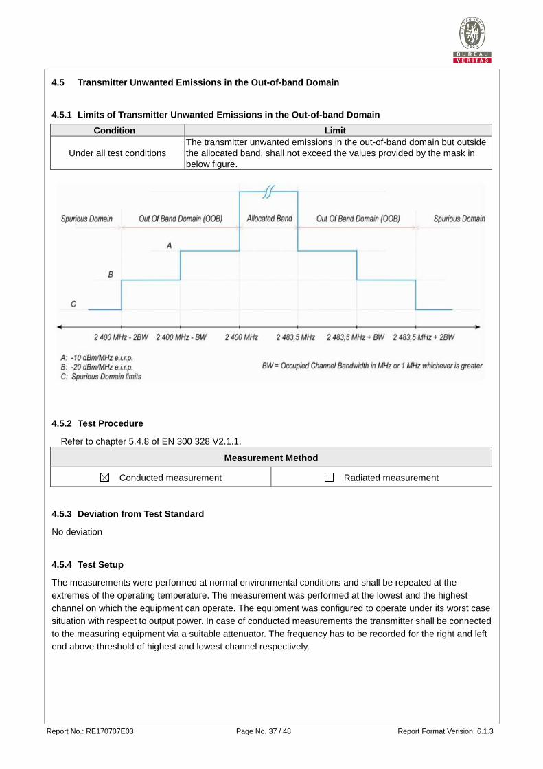
4.5 Transmitter Unwanted Emissions in the Out-of-band Domain
4.5.1 Limits of Transmitter Unwanted Emissions in the Out-of-band Domain
4.5.2 Test Procedure
Refer to chapter 5.4.8 of EN 300 328 V2.1.1.
Measurement Method
Conducted measurement Radiated measurement
4.5.3 Deviation from Test Standard
No deviation
4.5.4 Test Setup
The measurements were performed at normal environmental conditions and shall be repeated at the
extremes of the operating temperature. The measurement was performed at the lowest and the highest
channel on which the equipment can operate. The equipment was configured to operate under its worst case
situation with respect to output power. In case of conducted measurements the transmitter shall be connected
to the measuring equipment via a suitable attenuator. The frequency has to be recorded for the right and left
end above threshold of highest and lowest channel respectively.
Condition Limit
Under all test conditions
The transmitter unwanted emissions in the out-of-band domain but outside
the allocated band, shall not exceed the values provided by the mask in
below figure.
Report No.: RE170707E03 Page No. 38 / 48 Report Format Verision: 6.1.3
4.5.5 Test Results
802.11b
Channel Frequency 2412 MHz 2472 MHz
Test Condition
OOB Emission (MHz) OOB Emission (MHz)
2384.68
~ 2400 2369.36
~ 2384.68 2483.5
~ 2498.86 2498.86
~ 2514.22
Freq.
(MHz)
Power
(dBm/
MHz)
Freq.
(MHz)
Power
(dBm/
MHz)
Freq.
(MHz)
Power
(dBm/
MHz)
Freq.
(MHz)
Power
(dBm/
MHz)
Tnom 25℃ Vnom(v) 2399.50 -29.42 2384.18 -52.59 2484.00 -29.49 2499.36 -51.22
Limit (dBm/MHz) -10.00 -20.00 -10.00 -20.00
Pass/Fail Pass Pass Pass Pass
802.11g
Channel Frequency 2412 MHz 2472 MHz
Test Condition
OOB Emission (MHz) OOB Emission (MHz)
2382.88
~ 2400 2365.76
~ 2382.88 2483.5
~ 2500.66 2500.66
~ 2517.82
Freq.
(MHz)
Power
(dBm/
MHz)
Freq.
(MHz)
Power
(dBm/
MHz)
Freq.
(MHz)
Power
(dBm/
MHz)
Freq.
(MHz)
Power
(dBm/
MHz)
Tnom 25℃ Vnom(v) 2399.50 -27.52 2382.38 -48.27 2484.00 -23.35 2501.16 -46.56
Limit (dBm/MHz) -10.00 -20.00 -10.00 -20.00
Pass/Fail Pass Pass Pass Pass
802.11n (HT20)
Channel Frequency 2412 MHz 2472 MHz
Test Condition
OOB Emission (MHz) OOB Emission (MHz)
2381.72
~ 2400 2363.44
~ 2381.72 2483.5
~ 2501.82 2501.82
~ 2520.14
Freq.
(MHz)
Power
(dBm/
MHz)
Freq.
(MHz)
Power
(dBm/
MHz)
Freq.
(MHz)
Power
(dBm/
MHz)
Freq.
(MHz)
Power
(dBm/
MHz)
Tnom 25℃ Vnom(v) 2399.50 -26.25 2381.22 -48.81 2484.00 -24.31 2502.32 -45.55
Limit (dBm/MHz) -10.00 -20.00 -10.00 -20.00
Pass/Fail Pass Pass Pass Pass
Report No.: RE170707E03 Page No. 39 / 48 Report Format Verision: 6.1.3
4.6 Transmitter Spurious Emissions in the spurious domain
4.6.1 Limits of Transmitter Spurious Emissions
Frequency Range Maximum Power Limit Bandwidth
30 MHz to 47 MHz -36dBm 100kHz
47 MHz to 74 MHz -54dBm 100kHz
74 MHz to 87,5 MHz -36dBm 100kHz
87,5 MHz to 118 MHz -54dBm 100kHz
118 MHz to 174 MHz -36dBm 100kHz
174 MHz to 230 MHz -54dBm 100kHz
230 MHz to 470 MHz -36dBm 100kHz
470 MHz to 862 MHz -54dBm 100kHz
862 MHz to 1 GHz -36dBm 100kHz
1GHz ~ 12.75GHz -30dBm 1MHz
Note: These limits are e.r.p. for emissions up to 1 GHz and as e.i.r.p. for emissions above 1 GHz.
4.6.2 Test Procedure
Refer to chapter 5.4.9 of EN 300 328 V2.1.1.
Measurement Method
Conducted measurement Radiated measurement
For Conducted measurement:
The level of unwanted emissions shall be measured as their power in a specified load (conducted
spurious emissions) and their effective radiated power when radiated by the cabinet or structure of the
equipment with the antenna connector(s) terminated by a specified load (cabinet radiation).
Conducted measurement (For equipment with multiple transmit chains):
Option 1: The results for each of the transmit chains for the corresponding 1MHz segments shall be
added and compared with the limits.
Option 2: The results for each of the transmit chains shall be individually compared with the limits
after these limits have been reduced by 10 x log (N) (number of active transmit chains)
4.6.3 Deviation from Test Standard
No deviation.
4.6.4 Test Setup
1. For the actual test configuration, please refer to the related Item in this test report (Photographs of the
Test Configuration).
2. The equipment was configured to operate under its worst case situation with respect to output power.
3. The test setup has been constructed as the normal use condition. Controlling software (HyperTerminal
paste POP camera_Tx command.txt command)has been activated to set the EUT on specific status.
Report No.: RE170707E03 Page No. 40 / 48 Report Format Verision: 6.1.3
4.6.5 Test Results
Below 1GHz Worst-case Data
802.11n (HT20)
SPURIOUS EMISSION
FREQUENCY RANGE 30MHz ~ 1GHz OPERATING CHANNEL 13
SPURIOUS EMISSION LEVEL
Frequency
(MHz)
Antenna
Polarization
Level
(dBm)
Limit
(dBm)
Margin
(dB)
96.01 V -70.03 -54.00 -16.03
214.81 H -74.65 -54.00 -20.65
501.15 H -74.80 -54.00 -20.80
599.99 H -74.93 -54.00 -20.93
599.99 V -71.26 -54.00 -17.26
644.32 V -73.46 -54.00 -19.46
672.97 V -68.65 -54.00 -14.65
673.02 H -68.20 -54.00 -14.20
696.00 V -67.92 -54.00 -13.92
701.62 H -74.02 -54.00 -20.02
719.98 V -69.07 -54.00 -15.07
730.28 H -69.03 -54.00 -15.03
744.01 V -69.40 -54.00 -15.40
760.42 H -71.23 -54.00 -17.23
787.53 H -69.10 -54.00 -15.10
792.01 V -68.04 -54.00 -14.04
816.19 H -68.94 -54.00 -14.94
816.19 V -69.02 -54.00 -15.02
840.02 V -67.82 -54.00 -13.82
850.61 H -69.80 -54.00 -15.80
Report No.: RE170707E03 Page No. 41 / 48 Report Format Verision: 6.1.3
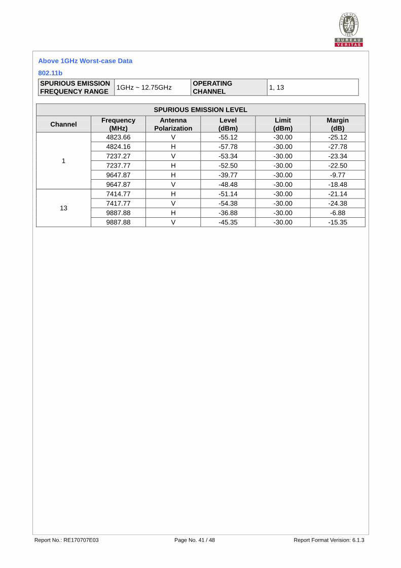
Above 1GHz Worst-case Data
802.11b
SPURIOUS EMISSION
FREQUENCY RANGE 1GHz ~ 12.75GHz
OPERATING
CHANNEL 1, 13
SPURIOUS EMISSION LEVEL
Channel Frequency
(MHz)
Antenna
Polarization
Level
(dBm)
Limit
(dBm)
Margin
(dB)
1
4823.66 V -55.12 -30.00 -25.12
4824.16 H -57.78 -30.00 -27.78
7237.27 V -53.34 -30.00 -23.34
7237.77 H -52.50 -30.00 -22.50
9647.87 H -39.77 -30.00 -9.77
9647.87 V -48.48 -30.00 -18.48
13
7414.77 H -51.14 -30.00 -21.14
7417.77 V -54.38 -30.00 -24.38
9887.88 H -36.88 -30.00 -6.88
9887.88 V -45.35 -30.00 -15.35
Report No.: RE170707E03 Page No. 42 / 48 Report Format Verision: 6.1.3
4.7 Receiver Spurious Emissions
4.7.1 Limit of Receiver Spurious Radiation
Frequency Range Maximum Power Limit Bandwidth
30 MHz ~ 1 GHz -57dBm 100 kHz
1 GHz ~ 12.75 GHz -47dBm 1 MHz
Note: These limits are e.r.p. for emissions up to 1 GHz and as e.i.r.p. for emissions above 1 GHz.
4.7.2 Test Procedure
Refer to chapter 5.4.10 of EN 300 328 V2.1.1.
Measurement Method
Conducted measurement Radiated measurement
For Conducted measurement:
The level of unwanted emissions shall be measured as their power in a specified load (conducted spurious
emissions) and their effective radiated power when radiated by the cabinet or structure of the equipment
with the antenna connector(s) terminated by a specified load (cabinet radiation).
Conducted measurement (For equipment with multiple transmit chains):
Option 1: The results for each of the transmit chains for the corresponding 1MHz segments shall be
added and compared with the limits.
Option 2: The results for each of the transmit chains shall be individually compared with the limits
after these limits have been reduced by 10 x log (N) (number of active transmit chains)
4.7.3 Deviation from Test Standard
No deviation.
4.7.4 Test Setup
1. For the actual test configuration, please refer to the related Item in this test report (Photographs of the
Test Configuration).
2. Testing was performed when the equipment was in a receive-only mode.
3. The test setup has been constructed as the normal use condition. Controlling software (HyperTerminal
paste POP camera_Tx command.txt command) has been activated to set the EUT on specific status.
Report No.: RE170707E03 Page No. 43 / 48 Report Format Verision: 6.1.3
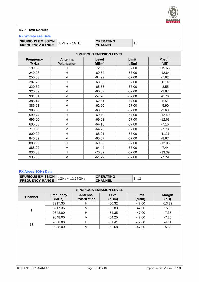
4.7.5 Test Results
RX Worst-case Data
SPURIOUS EMISSION
FREQUENCY RANGE 30MHz ~ 1GHz
OPERATING
CHANNEL 13
SPURIOUS EMISSION LEVEL
Frequency
(MHz)
Antenna
Polarization
Level
(dBm)
Limit
(dBm)
Margin
(dB)
199.98 H -72.66 -57.00 -15.66
249.98 H -69.64 -57.00 -12.64
250.03 V -64.92 -57.00 -7.92
287.73 H -68.02 -57.00 -11.02
320.62 H -65.55 -57.00 -8.55
320.62 V -60.87 -57.00 -3.87
331.61 V -57.70 -57.00 -0.70
385.14 V -62.51 -57.00 -5.51
386.03 V -62.90 -57.00 -5.90
386.08 H -60.63 -57.00 -3.63
599.74 H -69.40 -57.00 -12.40
696.00 H -69.63 -57.00 -12.63
696.00 V -64.16 -57.00 -7.16
719.98 V -64.73 -57.00 -7.73
800.02 H -68.21 -57.00 -11.21
840.02 V -65.67 -57.00 -8.67
888.02 H -69.06 -57.00 -12.06
888.02 V -64.44 -57.00 -7.44
936.03 H -70.39 -57.00 -13.39
936.03 V -64.29 -57.00 -7.29
RX Above 1GHz Data
SPURIOUS EMISSION
FREQUENCY RANGE 1GHz ~ 12.75GHz
OPERATING
CHANNEL 1, 13
SPURIOUS EMISSION LEVEL
Channel Frequency
(MHz)
Antenna
Polarization
Level
(dBm)
Limit
(dBm)
Margin
(dB)
1
3217.35 H -60.32 -47.00 -13.32
3217.35 V -62.83 -47.00 -15.83
9648.00 H -54.35 -47.00 -7.35
9648.00 V -54.25 -47.00 -7.25
13 9888.00 H -51.41 -47.00 -4.41
9888.00 V -52.68 -47.00 -5.68
Report No.: RE170707E03 Page No. 44 / 48 Report Format Verision: 6.1.3
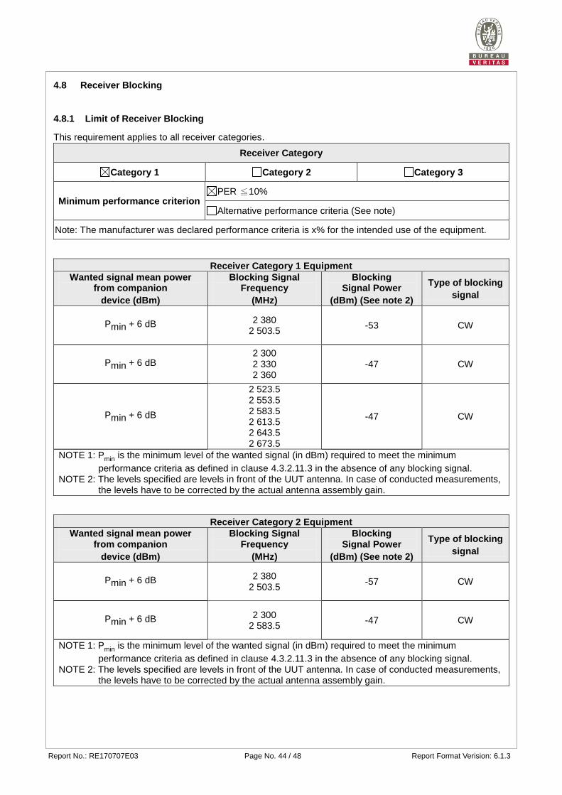
4.8 Receiver Blocking
4.8.1 Limit of Receiver Blocking
This requirement applies to all receiver categories.
Receiver Category
Category 1 Category 2 Category 3
Minimum performance criterion PER ≦10%
Alternative performance criteria (See note)
Note: The manufacturer was declared performance criteria is x% for the intended use of the equipment.
Receiver Category 1 Equipment
Wanted signal mean power from companion
device (dBm)
Blocking Signal Frequency
(MHz)
Blocking Signal Power
(dBm) (See note 2)
Type of blocking
signal
Pmin + 6 dB 2 380 2 503.5
-53 CW
Pmin + 6 dB 2 300 2 330 2 360
-47 CW
Pmin + 6 dB
2 523.5 2 553.5 2 583.5 2 613.5 2 643.5 2 673.5
-47 CW
NOTE 1: Pmin is the minimum level of the wanted signal (in dBm) required to meet the minimum
performance criteria as defined in clause 4.3.2.11.3 in the absence of any blocking signal. NOTE 2: The levels specified are levels in front of the UUT antenna. In case of conducted measurements,
the levels have to be corrected by the actual antenna assembly gain.
Receiver Category 2 Equipment
Wanted signal mean power from companion
device (dBm)
Blocking Signal Frequency
(MHz)
Blocking Signal Power
(dBm) (See note 2)
Type of blocking
signal
Pmin + 6 dB 2 380 2 503.5
-57 CW
Pmin + 6 dB 2 300 2 583.5
-47 CW
NOTE 1: Pmin is the minimum level of the wanted signal (in dBm) required to meet the minimum
performance criteria as defined in clause 4.3.2.11.3 in the absence of any blocking signal. NOTE 2: The levels specified are levels in front of the UUT antenna. In case of conducted measurements,
the levels have to be corrected by the actual antenna assembly gain.
Report No.: RE170707E03 Page No. 45 / 48 Report Format Verision: 6.1.3
Receiver Category 3 Equipment
Wanted signal mean power from companion
device (dBm)
Blocking Signal Frequency
(MHz)
Blocking Signal Power
(dBm) (See note 2)
Type of blocking
signal
Pmin + 12 dB 2 380 2 503.5
-57 CW
Pmin + 12 dB 2 300 2 583.5
-47 CW
NOTE 1: Pmin is the minimum level of the wanted signal (in dBm) required to meet the minimum
performance criteria as defined in clause 4.3.2.11.3 in the absence of any blocking signal. NOTE 2: The levels specified are levels in front of the UUT antenna. In case of conducted measurements,
the levels have to be corrected by the actual antenna assembly gain.
4.8.2 Test Procedure
Refer to chapter 5.4.11 of EN 300 328 V2.1.1.
Measurement Method
Conducted measurement Radiated measurement
4.8.3 Deviation from Test Standard
No deviation.
4.8.4 Test Setup Configuration
Report No.: RE170707E03 Page No. 46 / 48 Report Format Verision: 6.1.3
4.8.5 Test Results
Receiver Category 1 Equipment
Receiver blocking performance when operating at the lowest operating channel
Pmin: -95dBm antenna gain(G) : -1.49 dBi
The actual blocking signal power(Note1) at the antenna connector
in front of the antenna
Note1: For the conducted measurements , the level shall be corrected as follows: the actual blocking signal power = blocking signal power + G
Operation
Mode Channel
Wanted signal
mean power from
companion device
(dBm)
Blocking signal
frequency
(MHz)
The actual
blocking signal
power (dBm)
Pass/Fail
802.11b 1 -89
2380 -54.49 Pass 2503.5 -54.49 Pass
2300 -48.49 Pass
2330 -48.49 Pass
2360 -48.49 Pass
2523.5 -48.49 Pass
2553.5 -48.49 Pass
2583.5 -48.49 Pass
2613.5 -48.49 Pass
2643.5 -48.49 Pass
2673.5 -48.49 Pass
Receiver blocking performance when operating at the highest operating channel
Pmin: -95dBm antenna gain(G) : -1.49 dBi
The actual blocking signal power(Note1) at the antenna connector
in front of the antenna
Note1: For the conducted measurements , the level shall be corrected as follows: the actual blocking signal power = blocking signal power + G
Operation
Mode Channel
Wanted signal
mean power from
companion device
(dBm)
Blocking signal
frequency
(MHz)
The actual
blocking signal
power (dBm)
Pass/Fail
802.11b 13 -89
2380 -54.49 Pass
2503.5 -54.49 Pass
2300 -48.49 Pass
2330 -48.49 Pass
2360 -48.49 Pass
2523.5 -48.49 Pass
2553.5 -48.49 Pass
2583.5 -48.49 Pass
2613.5 -48.49 Pass
2643.5 -48.49 Pass
2673.5 -48.49 Pass
Report No.: RE170707E03 Page No. 47 / 48 Report Format Verision: 6.1.3
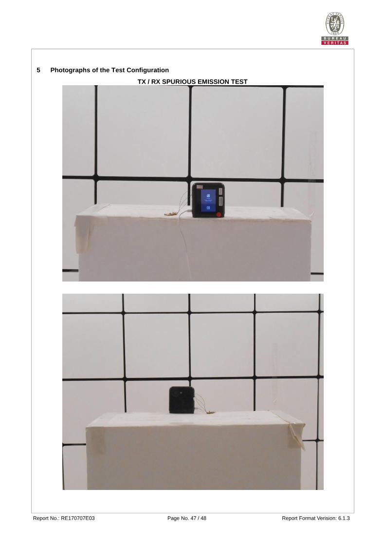
5 Photographs of the Test Configuration
TX / RX SPURIOUS EMISSION TEST
TX / RX SPURIOUS EMISSION TEST
Report No.: RE170707E03 Page No. 48 / 48 Report Format Verision: 6.1.3
Appendix - Information on the Testing Laboratories
We, Bureau Veritas Consumer Products Services (H.K.) Ltd., Taoyuan Branch, were founded in 1988 to
provide our best service in EMC, Radio, Telecom and Safety consultation. Our laboratories are accredited and
approved according to ISO/IEC 17025.
If you have any comments, please feel free to contact us at the following:
Linko EMC/RF Lab
Tel: 886-2-26052180
Fax: 886-2-26051924
Hsin Chu EMC/RF/Telecom Lab
Tel: 886-3-6668565
Fax: 886-3-6668323
Hwa Ya EMC/RF/Safety Lab
Tel: 886-3-3183232
Fax: 886-3-3270892
Email: [email protected]
Web Site: www.bureauveritas-adt.com
The address and road map of all our labs can be found in our web site also.
--- END ---