Embed Size (px)
Citation preview
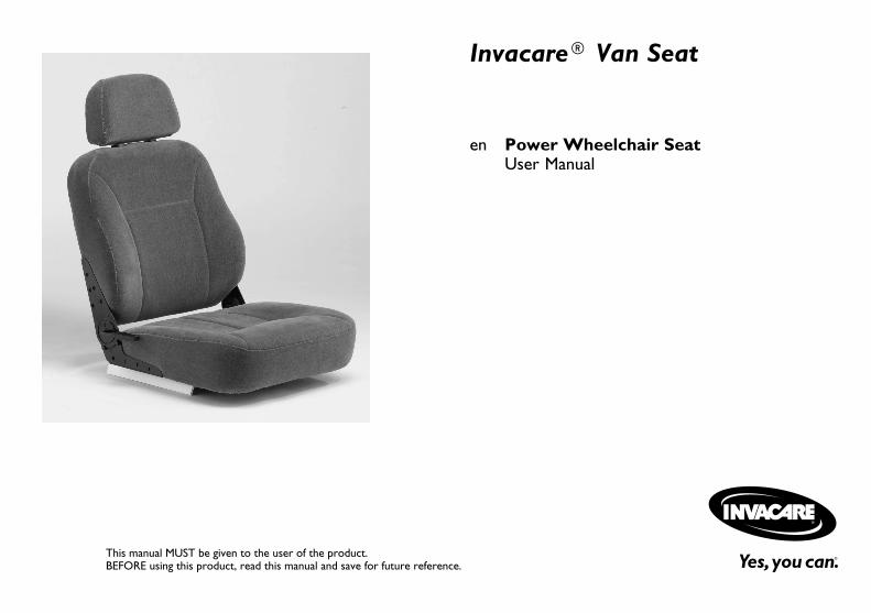
Invacare® Van Seat
en Power Wheelchair SeatUser Manual
This manual MUST be given to the user of the product.BEFORE using this product, read this manual and save for future reference.

©2015 Invacare®CorporationAll rights reserved. Republication, duplication or modification in whole or in part is prohibited withoutprior written permission from Invacare. Trademarks are identified by ™and ®. All trademarks areowned by or licensed to Invacare Corporation or its subsidiaries unless otherwise noted.

Contents
1 General . . . . . . . . . . . . . . . . . . . . . . . . . . . . . . . . . . . . . . . . 51.1 Symbols . . . . . . . . . . . . . . . . . . . . . . . . . . . . . . . . . . . . . 51.2 Reference Documents . . . . . . . . . . . . . . . . . . . . . . . . . . . 51.3 General Guidelines . . . . . . . . . . . . . . . . . . . . . . . . . . . . . 51.3.1 Set Up . . . . . . . . . . . . . . . . . . . . . . . . . . . . . . . . . . . . 71.3.2 Transport. . . . . . . . . . . . . . . . . . . . . . . . . . . . . . . . . . 81.3.3 Repair or Service Information (Dealers and/or
Qualified Technicians) . . . . . . . . . . . . . . . . . . . . . . . . 91.3.4 Wear and Tear Information. . . . . . . . . . . . . . . . . . . . . 91.3.5 Global Limited Warranty (Excluding Canada) . . . . . . . . 10
2 Safety Handling . . . . . . . . . . . . . . . . . . . . . . . . . . . . . . . . . . 122.1 Safety/Handling . . . . . . . . . . . . . . . . . . . . . . . . . . . . . . . . 122.1.1 Stability and Balance . . . . . . . . . . . . . . . . . . . . . . . . . . 142.1.2 Footplates and Front Rigging . . . . . . . . . . . . . . . . . . . . 142.1.3 Reaching, Leaning and Bending - Forward . . . . . . . . . . . 152.1.4 Reaching, Bending - Backward . . . . . . . . . . . . . . . . . . . 152.1.5 Pinch Points . . . . . . . . . . . . . . . . . . . . . . . . . . . . . . . . 152.1.6 Transferring To and From Other Seats . . . . . . . . . . . . 152.1.7 Storage . . . . . . . . . . . . . . . . . . . . . . . . . . . . . . . . . . . 162.1.8 Weight Training . . . . . . . . . . . . . . . . . . . . . . . . . . . . . 162.1.9 Weight Capacity . . . . . . . . . . . . . . . . . . . . . . . . . . . . . 162.1.10 Electromagnetic Interference (EMI) From Radio
Wave Sources . . . . . . . . . . . . . . . . . . . . . . . . . . . . . 172.1.11 Powered Wheelchair Electromagnetic Interference
(EMI) . . . . . . . . . . . . . . . . . . . . . . . . . . . . . . . . . . . . 18
3 Label Locations . . . . . . . . . . . . . . . . . . . . . . . . . . . . . . . . . . 193.1 Label Locations . . . . . . . . . . . . . . . . . . . . . . . . . . . . . . . . 19
4 Technical Data . . . . . . . . . . . . . . . . . . . . . . . . . . . . . . . . . . 204.1 Specifications . . . . . . . . . . . . . . . . . . . . . . . . . . . . . . . . . . 20
5 Usage . . . . . . . . . . . . . . . . . . . . . . . . . . . . . . . . . . . . . . . . . . 215.1 Operation Warnings . . . . . . . . . . . . . . . . . . . . . . . . . . . . 215.2 Preparing the Joystick for Use. . . . . . . . . . . . . . . . . . . . . . 215.3 A Note About Drive Lock-Out. . . . . . . . . . . . . . . . . . . . . 225.4 Operating Powered Seating Systems . . . . . . . . . . . . . . . . . 235.4.1 Using the Single Function Switch . . . . . . . . . . . . . . . . . 235.4.2 Using the MK6i™ SPJ+™ w/ACC Joystick . . . . . . . . . . 245.4.3 Using the CMPJ+ Joystick . . . . . . . . . . . . . . . . . . . . . . 245.4.4 Programmable Mono Ports 1 and 2 with External
Mode Switch. . . . . . . . . . . . . . . . . . . . . . . . . . . . . . . 265.4.5 Remote On/Off Switch . . . . . . . . . . . . . . . . . . . . . . . . 265.4.6 Mode Switch . . . . . . . . . . . . . . . . . . . . . . . . . . . . . . . 275.4.7 Memory Card Slot . . . . . . . . . . . . . . . . . . . . . . . . . . . 27
5.5 About Front Riggings . . . . . . . . . . . . . . . . . . . . . . . . . . . . 275.6 Raising/Lowering Elevating Front Riggings . . . . . . . . . . . . . 285.7 Adjusting Calfpads . . . . . . . . . . . . . . . . . . . . . . . . . . . . . . 29
6 Setup and Maintenance . . . . . . . . . . . . . . . . . . . . . . . . . . . 306.1 Setup/Maintenance Information. . . . . . . . . . . . . . . . . . . . . 306.2 Setup/Delivery Inspection . . . . . . . . . . . . . . . . . . . . . . . . . 306.3 User/Attendant Inspection Checklists . . . . . . . . . . . . . . . . 316.3.1 Inspect/Adjust Weekly . . . . . . . . . . . . . . . . . . . . . . . . 316.3.2 Inspect/Adjust Monthly . . . . . . . . . . . . . . . . . . . . . . . . 316.3.3 Inspect/Adjust Periodically. . . . . . . . . . . . . . . . . . . . . . 31
6.4 Service Inspection . . . . . . . . . . . . . . . . . . . . . . . . . . . . . . 316.4.1 Six Month Inspection . . . . . . . . . . . . . . . . . . . . . . . . . 32
6.5 Troubleshooting . . . . . . . . . . . . . . . . . . . . . . . . . . . . . . . 326.6 Installing/Removing Front Riggings. . . . . . . . . . . . . . . . . . . 336.6.1 Installing Front Riggings . . . . . . . . . . . . . . . . . . . . . . . . 336.6.2 Removing Front Riggings . . . . . . . . . . . . . . . . . . . . . . . 33
6.7 Replacing Heel Loops. . . . . . . . . . . . . . . . . . . . . . . . . . . . 336.8 Removing/Installing the Manual Center Mount
Footrest . . . . . . . . . . . . . . . . . . . . . . . . . . . . . . . . . . . . 346.8.1 Installing. . . . . . . . . . . . . . . . . . . . . . . . . . . . . . . . . . . 34

6.8.2 Removing . . . . . . . . . . . . . . . . . . . . . . . . . . . . . . . . . . 346.9 Adjusting/Replacing Telescoping Front Rigging
Supports . . . . . . . . . . . . . . . . . . . . . . . . . . . . . . . . . . . . 356.10 Footrest Height Adjustment . . . . . . . . . . . . . . . . . . . . . . 366.10.1 Model PHWH93. . . . . . . . . . . . . . . . . . . . . . . . . . . . 366.10.2 PH904A and PHAL4A . . . . . . . . . . . . . . . . . . . . . . . . 37
6.11 Adjusting the Height of the Manual Center MountFootrest . . . . . . . . . . . . . . . . . . . . . . . . . . . . . . . . . . . . 37
6.12 Adjusting the Angle of the Manual Center MountFootrest . . . . . . . . . . . . . . . . . . . . . . . . . . . . . . . . . . . . 38
6.13 Adjusting the Footplate Width of the Center MountFootrest . . . . . . . . . . . . . . . . . . . . . . . . . . . . . . . . . . . . 39
6.14 Adjusting the Footplate Angle . . . . . . . . . . . . . . . . . . . . . 406.15 Adjusting the Tension of the Flip Up Footplate. . . . . . . . . 416.16 Removing/Installing/Adjusting the Adjustable Heel
Loop . . . . . . . . . . . . . . . . . . . . . . . . . . . . . . . . . . . . . . 416.16.1 Removing the Adjustable Heel Loop. . . . . . . . . . . . . . 416.16.2 Installing the Adjustable Heel Loop. . . . . . . . . . . . . . . 426.16.3 Adjusting the Adjustable Heel Loop . . . . . . . . . . . . . . 42
6.17 Adjusting Armrests . . . . . . . . . . . . . . . . . . . . . . . . . . . . 436.17.1 Adjusting the Armrest Angle . . . . . . . . . . . . . . . . . . . 436.17.2 Adjusting the Height . . . . . . . . . . . . . . . . . . . . . . . . . 43
6.18 Adjusting the Back Angle . . . . . . . . . . . . . . . . . . . . . . . . 446.19 Adjusting the Headrest . . . . . . . . . . . . . . . . . . . . . . . . . . 446.20 Checking Seating System Mounting Position . . . . . . . . . . . 456.21 Adjusting the Seating System Mounting Position . . . . . . . . 46
General
1 General
1.1 SymbolsSignal symbols and/or words are used in this manual and apply tohazards or unsafe practices which could result in personal injury orproperty damage. See the information below for definitions of thesignal words.
DANGER!– Danger indicates a imminently hazardous situationwhich, if not avoided, could result in death or seriousinjury.
WARNING!– Warning indicates a potentially hazardous situationwhich, if not avoided, could result in death or seriousinjury.
CAUTION!– Caution indicates a potentially hazardous situationwhich, if not avoided, may result in property damageor minor injury or both.
IMPORTANT– Indicates a hazardous situation that could result indamage to property if it is not avoided.
Gives useful tips, recommendations and information forefficient, trouble-free use.
1.2 Reference Documents
WARNING!– Refer to the wheelchair base user manual foradditional safety and operation information
Refer to the table below for part numbers of additionaldocuments which are referenced in this manual.
MANUAL PART NUMBER
MK6i™ ElectronicsProgramming Guide
1141471
1.3 General GuidelinesThe safety section contains important information for the safeoperation and use of this product.
DANGER!Risk of Death, Injury or DamageImproper use of this product may cause injury or damage– If you are unable to understand the warnings, cautionsor instructions, contact a health care professional ordealer before attempting to use this equipment.
– DO NOT use this product or any available optionalequipment without first completely reading andunderstanding these instructions and any additionalinstructional material such as user manual, servicemanuals or instruction sheets supplied with thisproduct or optional equipment.
1143195-H~03 5

Invacare® Van Seat
DANGER!Risk of Death, Serious Injury, or DamageIncorrect repair and/or servicing of this wheelchairperformed by users/caregivers or unqualified technicianscan result in death, serious injury, or damage.– Users/Caregivers — DO NOT attempt to repairand/or service this wheelchair.
– Repair and/or service of this wheelchair MUST beperformed by a qualified technician. Contact a dealeror Invacare technician.
WARNING!– DO NOT connect any medical devices such asventilators, life support machines, etc. directly tothe batteries used to power the wheelchair. Thiscould cause unexpected failure of the device and thewheelchair.
WARNING!Risk of Serious Injury or DamageUse of non-Invacare accessories may result in seriousinjury or damage.– Invacare products are specifically designed andmanufactured for use in conjunction with Invacareaccessories. Accessories designed by othermanufacturers have not been tested by Invacare andare not recommended for use with Invacare products.
– DO NOT use non-Invacare accessories.– To obtain Invacare accessories, contact Invacare byphone or at www.invacare.com
DANGER!Risk of Death, Serious Injury, or DamageUse of incorrect or improper replacement (service)parts may cause death, serious injury, or damage.– Replacement parts MUST match original Invacareparts.
– ALWAYS provide the wheelchair serial number toassist in ordering the correct replacement parts.
WARNING!Risk of Serious Injury or DamageAttaching hardware that is loosely secured could causeloss of stability resulting in serious injury or damage.– After ANY adjustments, repair or service and beforeuse, make sure that all attaching hardware is tightenedsecurely.
DANGER!Risk of Death, Serious Injury, or DamageMissing attaching hardware could cause instabilityresulting in death, serious injury or damage.– Ensure all attaching hardware is present and tightenedsecurely
WARNING!Risk of Serious Injury or DamageLoss of power due to loose electrical connectionscould cause the wheelchair to suddenly stop resulting inserious injury or damage.– ALWAYS ensure that all electrical connections aretightly connected so they don’t vibrate loose.
6 1143195-H~03
General
THE INFORMATION CONTAINED IN THIS DOCUMENTIS SUBJECT TO CHANGE WITHOUT NOTICE.
Check all parts for shipping damage and test before using.In case of damage, DO NOT use. Contact Invacare/Carrierfor further instruction
As a manufacturer of wheelchairs, Invacare endeavors tosupply a wide variety of wheelchairs to meet many needsof the end user. However, final selection of the type ofwheelchair to be used by an individual rests solely withthe user and his/her healthcare professional capable ofmaking such a selection. Invacare recommends workingwith a qualified rehab technology provider, such as an ATP,(Assisstive Technology Professional).
1.3.1 Set Up
WARNING!Risk of Injury or DamageIncorrect set up of this wheelchair performed byusers/caregivers or unqualified technicians can result ininjury or damage.– User/Caregivers- DO NOT attempt to set up thiswheelchair.
– Initial set up of this wheelchair MUST be performedby a qualified technician.
DANGER!Risk of Death, Serious Injury, or DamageContinued use of the wheelchair that is not set to thecorrect specifications may cause erratic behavior of thewheelchair resulting in death, serious injury, or damage.– Performance adjustments should only be made byprofessionals of the healthcare field or personsfully conversant with this process and the driver'scapabilities.
– After the wheelchair has been set up/adjusted, checkto make sure that the wheelchair performs to thespecifications entered during the set up procedure. Ifthe wheelchair does not perform to specifications,turn the wheelchair Off immediately and reenter setup specifications. Contact Invacare, if wheelchair stilldoes not perform to correct specifications.
WARNING!Risk of Serious Injury or DamageMoving the seating system from the factory setting mayreduce driver control, wheelchair stability, tractionand increase caster wear resulting in serious injury ordamage.– Move the seating system ONLY when necessary to fitthe wheelchair to the user.
– If the seating system must be moved, ALWAYS inspectthe wheelchair to ensure the front rigging DOES NOTinterfere with the front casters.
– If the seating system must be moved, ALWAYSinspect to ensure the wheelchair DOES NOT easilytip forward or backward.
1143195-H~03 7
Invacare® Van Seat
DANGER!Risk of Death, Serious Injury or DamageOperating the wheelchairs outdoor or in areas of poorlighting may result in death, serious injury, or damage.Operating the wheelchair near motor vehicles may resultin death, serious injury or damage.– DO NOT operate on roads, streets or highways.– Use caution when operating the wheelchair outdoorsat night or in areas with poor lighting.
– ALWAYS be aware of motor vehicles when using thewheelchair.
WARNING!Risk of Minor to Serious InjuryPinch points can cause minor to serious injury.– Be mindful of potential pinch points and use cautionwhen using this product.
WARNING!Risk of Serious InjuryImpacting objects in the surrounding environment cancause serious injury.– When maneuvering the wheelchair around, ALWAYShave assured cleared distance with all objects inenvironment.
WARNING!Risk of Serious InjurySharp edges can cause serious injury.– Be mindful that some parts may have sharp edges. Usecaution when encountering these sharp edges.
WARNING!Risk of Serious InjuryHot surfaces can cause severe burns.– Be mindful of potential hot surfaces and avoid touching.
DANGER!Risk of Death, Serious Injury, or DamageLighted cigarettes dropped onto an upholstered seatingsystem can cause a fire resulting in death, serious injury,or damage.Wheelchair occupants are at particular risk of deathor serious injury from these fires and resulting fumesbecause they may not have the ability to move awayfrom the wheelchair.– DO NOT smoke while using this wheelchair.
1.3.2 Transport
WARNING!– As of this date, the Department of Transportation hasnot approved any tie-down systems for transportationof a user while in a wheelchair, in a moving vehicleof any type. It is Invacare’s position that users ofwheelchairs should be transferred into appropriateseating in vehicles for transportation and use bemade of the restraints made available by the autoindustry. Invacare cannot and does not recommendany wheelchair transportation systems.
8 1143195-H~03
General
1.3.3 Repair or Service Information (Dealers and/orQualified Technicians)
DANGER !Risk of Death, Serious Injury, or DamageCorroded electrical components due to water, liquidexposure, or incontinent users can result in death,serious injury, or damage.– Minimize exposure of electrical components to waterand/or liquids. Electrical components damaged bycorrosion MUST be replaced immediately.
– Wheelchairs that are used by incontinent usersand/or are frequently exposed to water/liquids mayrequire replacement of electrical components morefrequently.
WARNING!– Except for programming, DO NOT service or adjustthe wheelchair while occupied, unless otherwisenoted.
– Before adjusting, repairing or servicing the wheelchair,Always turn the wheelchair power Off, otherwise,injury or damage may occur.
– DO NOT overtighten hardware attaching to theframe. This could cause damage to the frame tubing.
– Transport ready packages are not retrofittable toexisting models and are not field serviceable.
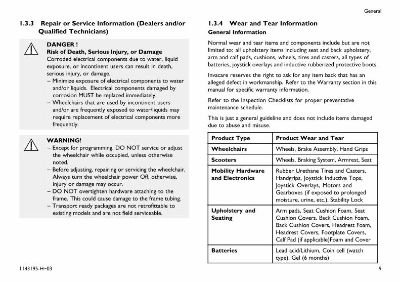
1.3.4 Wear and Tear InformationGeneral Information
Normal wear and tear items and components include but are notlimited to: all upholstery items including seat and back upholstery,arm and calf pads, cushions, wheels, tires and casters, all types ofbatteries, joystick overlays and inductive rubberized protective boots.
Invacare reserves the right to ask for any item back that has analleged defect in workmanship. Refer to the Warranty section in thismanual for specific warranty information.
Refer to the Inspection Checklists for proper preventativemaintenance schedule.
This is just a general guideline and does not include items damageddue to abuse and misuse.
Product Type Product Wear and Tear
Wheelchairs Wheels, Brake Assembly, Hand Grips
Scooters Wheels, Braking System, Armrest, Seat
Mobility Hardwareand Electronics
Rubber Urethane Tires and Casters,Handgrips, Joystick Inductive Tops,Joystick Overlays, Motors andGearboxes (if exposed to prolongedmoisture, urine, etc.), Stability Lock
Upholstery andSeating
Arm pads, Seat Cushion Foam, SeatCushion Covers, Back Cushion Foam,Back Cushion Covers, Headrest Foam,Headrest Covers, Footplate Covers,Calf Pad (if applicable)Foam and Cover
Batteries Lead acid/Lithium, Coin cell (watchtype), Gel (6 months)
1143195-H~03 9

Invacare® Van Seat
1.3.5 Global Limited Warranty (Excluding Canada)PLEASE NOTE: THE WARRANTY BELOW HASBEEN DRAFTED TO COMPLY WITH FEDERAL LAWAPPLICABLE TO PRODUCTS MANUFACTURED AFTERJULY 4, 1975.
This warranty is extended only to the original purchaser whopurchases this product within any country excluding CANADAwhen new and unused from Invacare or a dealer. This warranty isnot extended to any other person or entity and is not transferableor assignable to any subsequent purchaser or owner. Coverageunder this warranty will end upon any such subsequent sale or othertransfer of title to any other person. For product purchased inCanada, please refer to the Canada Limited Warranty.
This warranty gives you specific legal rights and you may also haveother legal rights which vary from state to state.
Invacare warrants the seat frame to be free from defects in materialsand workmanship for a period of three (3) years from the dateof purchase from Invacare or a dealer, with a copy of the seller’sinvoice required for coverage under this warranty. Invacare warrantsall remaining components (excluding all upholstered materialsand padded materials) to be free from defects in materials andworkmanship for a period of one (1) year from the date of purchasefrom Invacare or a dealer, with a copy of the seller’s invoice requiredfor coverage under this warranty. If within such warranty periods anysuch product component shall be proven to be defective, the productcomponent shall be repaired or replaced, at Invacare's option. Thiswarranty does not include any labor or shipping charges incurred inreplacement part installation or repair of any such product. Invacare'ssole obligation and your exclusive remedy under this warranty shallbe limited to such repair and/or replacement.
For warranty service, please contact the dealer from whom youpurchased your Invacare product. In the event you do not receivesatisfactory warranty service, please write directly to Invacare atthe address on the bottom of the back cover. Provide dealer'sname address, date of purchase, indicate nature of the defect and, ifthe product is serialized, indicate the serial number. Do not returnproducts to our factory without our prior consent.
Limitations and Exclusions: The foregoing warranty shall not applyto serial numbered products if the serial number has been removedor defaced, products subject to negligence, accident, improperoperation, maintenance or storage, commercial or institutionaluse, products modified without Invacare's express written consent(including, but not limited to, modification through the use ofunauthorized parts or attachments); products damaged by reasonof repairs made to any component without the specific consentof Invacare, or to a product damaged by circumstances beyondInvacare's control, and such evaluation will be solely determinedby Invacare. The warranty shall not apply to problems arisingfrom normal wear and tear or failure to adhere to the productinstructions. A change in operating noise, particularly relative tomotors and gearboxes does not constitute a failure or defect andwill not be repaired; all devices will exhibit changes in operatingnoise due to aging.
The foregoing express warranty is exclusive and in lieu of any otherwarranties whatsoever, whether express or implied, including theimplied warranties of merchantability and fitness for a particularpurpose, and the sole remedy for violations of any warrantywhatsoever, shall be limited to repair or replacement of the defectiveproduct pursuant to the terms contained herein. the applicationof any implied warranty whatsoever shall not extend beyond theduration of the express warranty provided herein and Invacare shallnot be liable for any consequential or incidental damages whatsoever;
10 1143195-H~03

General
SOME STATES DO NOT ALLOW THE EXCLUSION ORLIMITATION OF INCIDENTAL OR CONSEQUENTIAL DAMAGE,OR LIMITATION OF HOW LONG AN IMPLIED WARRANTYLASTS, SO THE ABOVE EXCLUSION AND LIMITATION MAYNOT BE APPLICABLE.
THIS WARRANTY SHALL BE EXTENDED TO COMPLY WITHSTATE/PROVINCIAL LAWS AND REQUIREMENTS.
1143195-H~03 11

Invacare® Van Seat
2 Safety Handling
2.1 Safety/Handling
WARNING!– Refer to wheelchair base user manual for additionalsafety and operation information.
– DO NOT leave the power button On when enteringor exiting your wheelchair.
– DO NOT go up or down ramps or traverse slopesgreater than 9°.
– Never leave an unoccupied wheelchair unattended onan incline.
– Do determine and establish your particular safetylimits by practicing bending, reaching and transferringactivities in the presence of a qualified healthcareprofessional before attempting active use of thewheelchair.
– Always shift your weight in the direction you areturning. Do not shift your weight in the oppositedirection of the turn. Shifting your weight in theopposite direction of the turn may cause the insidedrive wheel to lose traction and the wheelchair totip over.
WARNING!– DO NOT shift your weight or sitting position towardthe direction you are reaching as the wheelchairand/or seating system (if any) may tip over.
– Always keep hands and fingers clear of moving partsto avoid injury.
– DO NOT use with a broken or missing joystick knob.– DO NOT use if joystick does not spring back to theneutral position or becomes sticky or sluggish.
– DO NOT use if joystick boot is torn or damaged.– Always check foam grips for looseness before usingthe wheelchair. If loose, contact a qualified technicianfor instructions.
– DO NOT leave elevating legrests in the fully extendedposition when proceeding down ramps.
DANGER!Risk of Death, Serious Injury, or DamageMisuse of the wheelchair may cause component failureand/or the wheelchair to start smoking, sparking, orburning. Death, serious injury, or damage may occurdue to fire.– DO NOT use the wheelchair other than its intendedpurpose. If the wheelchair starts smoking, sparking, orburning, discontinue using the wheelchair and seekservice IMMEDIATELY.
12 1143195-H~03

Safety Handling
DANGER!Risk of Death or Serious InjuryElectric shock can cause death or serious injury– To avoid electric shock, inspect plug and cord forcuts and/or frayed wires. Replace cut cords or frayedwires immediately.
WARNING!Risk of Serious Injury or DamageDropping the battery can result in serious injury orproperty damage.– Batteries can weigh up to 52 lbs (23.6 kg). ALWAYSuse a battery lifting strap when lifting the battery. Itis the most reliable method of carrying a battery andpreventing serious injury.
WARNING!Risk of Death or Serious InjuryBraking hard and/or sudden stops while on inclines couldcause loss of stability resulting in death or serious injury.– While on inclines, ALWAYS travel at a reduced,constant speed to maintain stability. Traveling downramps at high speeds will reduce traction and increasestopping distance.
– DO NOT brake hard and avoid sudden stops whiletraveling on an incline.
– If stopping becomes necessary while on an incline,release the joystick and allow the wheelchair to cometo a full stop. Then proceed at a slower speed.
WARNING!Risk of injury or damageImproper mounting or maintenance of the Sip n’ Puffcontrol including the mouthpiece and breath tubemay cause injury or damage. Water inside the Sip n’Puff interface module may cause damage to the unit.Excessive saliva residue in the mouthpiece/straw canreduce performance. Blockages, a clogged saliva trapor air leaks in the system may cause Sip n’ Puff not tofunction properly.– Ensure moving parts of the wheelchair, including theoperation of powered seating DO NOT pinch ordamage the Sip n’ Puff tubing.
– Saliva trap MUST be installed to reduce risk of wateror saliva entering the Sip n’ Puff interface module.
– Occasionally flush the mouthpiece to remove salivaresidue.
– The mouthpiece/straw MUST be completely drybefore installation.
– If Sip n’ Puff does not function properly, inspectsystem for blockages, clogged saliva trap or air leaks.As necessary, replace mouthpiece, breath tube andsaliva trap.
WARNING!Risk of Serious Injury or DamageAccidental activation of wheelchair caused by pets,children, etc. can result in serious injury or damage.– ALWAYS turn power off when around pets and/orchildren to prevent unintended movement.
1143195-H~03 13
Invacare® Van Seat
2.1.1 Stability and Balance
DANGER!Risk of Death or Serious InjuryNot wearing your seat positioning strap could result indeath or serious injury.– ALWAYS wear your seat positioning strap. Yourseat positioning strap helps reduce the possibilityof a fall from the wheelchair. The seat positioningstrap is a positioning belt only. It is not designed foruse as a safety device withstanding high stress loadssuch as auto or aircraft safety belts. If signs of wearappear, seat positioning strap MUST be replacedIMMEDIATELY.
WARNING!– To determine and establish your particular safetylimits, practice use of this product on various slopingsurfaces in the presence of a qualified healthcareprovider before attempting active use of thiswheelchair. Other general warnings listed within thisdocument also apply.
– DO NOT stand on frame of the wheelchair.
2.1.2 Footplates and Front Rigging
WARNING!Risk of Serious Injury or DamageOperating the wheelchair with a ground clearance ofless than 75 mm (3 inches) between the footplates andthe ground/floor may cause serious injury or propertydamage.– ALWAYS maintain a minimum of 75 mm (3inches) between the bottom of the footplates andground/floor to ensure proper ground clearance whilethe wheelchair is in motion. If necessary, adjust thefootplates height to achieve proper ground clearance.After footplates height adjustment, if the wheelchairdips forward and the footplates touch the groundwhile in motion, please contact your dealer for aninspection and avoid use of the wheelchair if possible.
CAUTION!Risk of DamageInterference between footrests and front casters maycause damage.– When determining the depth of the telescoping frontframe tubes, make sure the rear of the footrests donot interfere with the movement of the front casters.Otherwise damage to the wheelchair may result ormay impede proper operation.
14 1143195-H~03
Safety Handling
2.1.3 Reaching, Leaning and Bending - Forward
WARNING!Risk of Serious Injury or DamageImproper positioning while leaning or bending couldcause the wheelchair to tip forward resulting in seriousinjury or damage.– To assure stability and proper operation of yourwheelchair, you MUST at all times maintain properbalance. Your wheelchair has been designed to remainupright and stable during normal daily activities as longas you DO NOT move beyond the center of gravity.DO NOT lean forward out of the wheelchair anyfurther than the length of the armrests.
– DO NOT attempt to reach objects if you have tomove forward in the seat or pick them up from thefloor by reaching down between your knees.
2.1.4 Reaching, Bending - Backward
WARNING!– DO NOT lean over the top of the back upholstery.This will change your center of gravity and may causethe wheelchair to tip over.
2.1.5 Pinch Points
WARNING!– DO NOT store or place items under the seat.– Pinch point may occur when adjusting the arm angleposition.
Refer to adjusting armrests for illustration of potential pinch point.
2.1.6 Transferring To and From Other Seats
WARNING!Risk of Serious Injury or DamageImproper transfer techniques may cause serious injuryor damage.– Before attempting transfers, consult a health careprofessional to determine proper transfer techniquesfor the user and type of wheelchair.
– Reduce gap between transfer surface and wheelchairseat to the minimum distance necessary to performtransfer.
– Align casters parallel to the drive wheels to improvestability during transfer.
– ALWAYS turn the wheelchair power off.– ALWAYS engage both motor locks/clutches andfree wheel hubs (if equipped) to prevent the wheelsfrom moving before transferring into or from thewheelchair.
WARNING!– ALWAYS turn the wheelchair power OFF and engagethe motor locks/clutches to prevent the wheels frommoving before attempting to transfer in or out of thewheelchair. Also make sure every precaution is takento reduce the gap distance. Align both casters parallelwith the object you are transferring onto.
1143195-H~03 15
Invacare® Van Seat
2.1.7 Storage
CAUTION!Risk of DamageOperating the wheelchair in rain or dampness maycause the wheelchair to malfunction electrically andmechanically; may cause the wheelchair to prematurelyrust or may damage the upholstery.– DO NOT leave wheelchair in a rain storm of any kind.– DO NOT use wheelchair in a shower.– DO NOT leave wheelchair in a damp area for anylength of time.
– Check to ensure that the battery covers are securedin place, joystick boot is NOT torn or cracked wherewater can enter and that all electrical connections aresecure at all times. DO NOT use if the joystick bootis torn or cracked. If the joystick boot becomes tornor cracked, replace IMMEDIATELY.
Invacare has tested its wheelchairs in accordance withRESNA WC — 2:2009, Section 9 Part 7.3 “Rain Test”. Thisprovides the end user or his/her attendant sufficient timeto remove his/her wheelchair from a rain storm and retainwheelchair operation.
WARNING!– Avoid storing or using the wheelchair near open flameor combustible products. Serious injury or damage toproperty may result.
2.1.8 Weight Training
WARNING!– Invacare DOES NOT recommend the use of itswheelchairs as a weight training apparatus. Invacarewheelchairs have NOT been designed or tested asa seat for any kind of weight training. If occupantuses said wheelchair as a weight training apparatus,Invacare shall NOT be liable for bodily injury and thewarranty is void.
2.1.9 Weight Capacity
WARNING!– Refer to Typical Product Parameters in this manualand the manual shipped with the wheelchair base todetermine the weight capacity (total combined weightof user and any attachments) of your wheelchairmodel.
16 1143195-H~03

Safety Handling
2.1.10 Electromagnetic Interference (EMI) FromRadio Wave Sources
Powered wheelchairs and motorized scooters (in this text, bothwill be referred to as powered wheelchairs) may be susceptibleto electromagnetic interference (EMI), which is interferingelectromagnetic energy (EM) emitted from sources such as radiostations, TV stations, amateur radio (HAM) transmitters, two wayradios, and cellular phones. The interference (from radio wavesources) can cause the powered wheelchair to release its brakes,move by itself, or move in unintended directions. It can alsopermanently damage the powered wheelchair's control system. Theintensity of the interfering EM energy can be measured in voltsper meter (V/m). Each powered wheelchair can resist EMI up to acertain intensity. This is called its "immunity level." The higher theimmunity level, the greater the protection. At this time, currenttechnology is capable of achieving at least a 20 V/m immunity level,which would provide useful protection from the more commonsources of radiated EMI.
There are a number of sources of relatively intense electromagneticfields in the everyday environment. Some of these sources areobvious and easy to avoid. Others are not apparent and exposureis unavoidable. However, we believe that by following the warningslisted below, your risk to EMI will be minimized.
The sources of radiated EMI can be broadly classified into three types:
1. Hand-held Portable transceivers (transmitters/receivers with theantenna mounted directly on the transmitting unit. Examplesinclude: citizens band (CB) radios, “walkie talkie”, security, fireand police transceivers, cellular telephones, and other personalcommunication devices).
Some cellular telephones and similar devices transmitsignals while they are ON, even when not being used.
2. Medium-range mobile transceivers, such as those used in policecars, fire trucks, ambulances and taxis. These usually have theantenna mounted on the outside of the vehicle.
3. Long-range transmitters and transceivers, such as commercialbroadcast transmitters (radio and TV broadcast antenna towers)and amateur (HAM) radios.
Other types of handheld devices, such as cordless phones,laptop computers, AM/FM radios, TV sets, CD players,cassette players, and small appliances, such as electricshavers and hair dryers, so far as we know, are not likely tocause EMI problems to your powered wheelchair.
1143195-H~03 17

Invacare® Van Seat
2.1.11 Powered Wheelchair ElectromagneticInterference (EMI)
Because EM energy rapidly becomes more intense as one movescloser to the transmitting antenna (source), the EM fields fromhandheld radio wave sources (transceivers) are of special concern.It is possible to unintentionally bring high levels of EM energy veryclose to the powered wheelchair's control system while using thesedevices. This can affect powered wheelchair movement and braking.Therefore, the warnings listed below are recommended to preventpossible interference with the control system of the poweredwheelchair.
Electromagnetic interference (EMI) from sources such as radio andTV stations, amateur radio (HAM) transmitters, two-way radios,and cellular phones can affect powered wheelchairs and motorizedscooters.
FOLLOWING THE WARNINGS LISTED BELOW SHOULDREDUCE THE CHANCE OF UNINTENDED BRAKE RELEASE ORPOWERED WHEELCHAIR MOVEMENT WHICH COULD RESULTIN SERIOUS INJURY.
WARNING!– DO NOT operate handheld transceivers (transmittersreceivers), such as citizens band (CB) radios, or turnON personal communication devices, such as cellularphones, while the powered wheelchair is turned ON;
– Be aware of nearby transmitters, such as radio or TVstations, and try to avoid coming close to them;
– If unintended movement or brake release occurs, turnthe powered wheelchair OFF as soon as it is safe;
WARNING!– Be aware that adding accessories or components, ormodifying the powered wheelchair, may make it moresusceptible to EMI (Note: There is no easy way toevaluate their effect on the overall immunity of thepowered wheelchair); and
– Report all incidents of unintended movement or brakerelease to the powered wheelchair manufacturer, andnote whether there is a source of EMI nearby.
WARNING!Important Information– 20 volts per meter (V/m) is a generally achievable anduseful immunity level against EMI (as of May 1994) (thehigher the level, the greater the protection);
– This device has been tested to a radiated immunitylevel of 20 volts per meter.
– The immunity level of the product is unknown.– Modification of any kind to the electronics of thispower wheelchair as manufactured by Invacare mayadversely affect the EMI immunity levels.
18 1143195-H~03
Label Locations
3 Label Locations
3.1 Label Locations
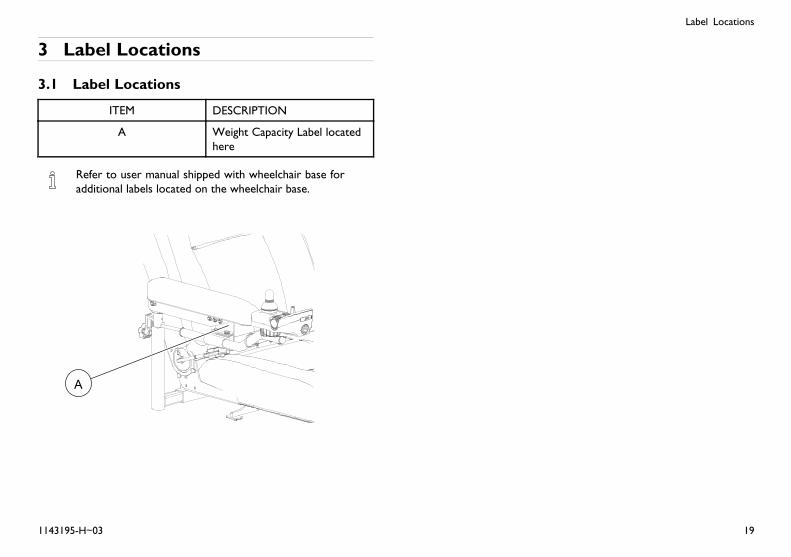
ITEM DESCRIPTION
A Weight Capacity Label locatedhere
Refer to user manual shipped with wheelchair base foradditional labels located on the wheelchair base.
1143195-H~03 19
Invacare® Van Seat
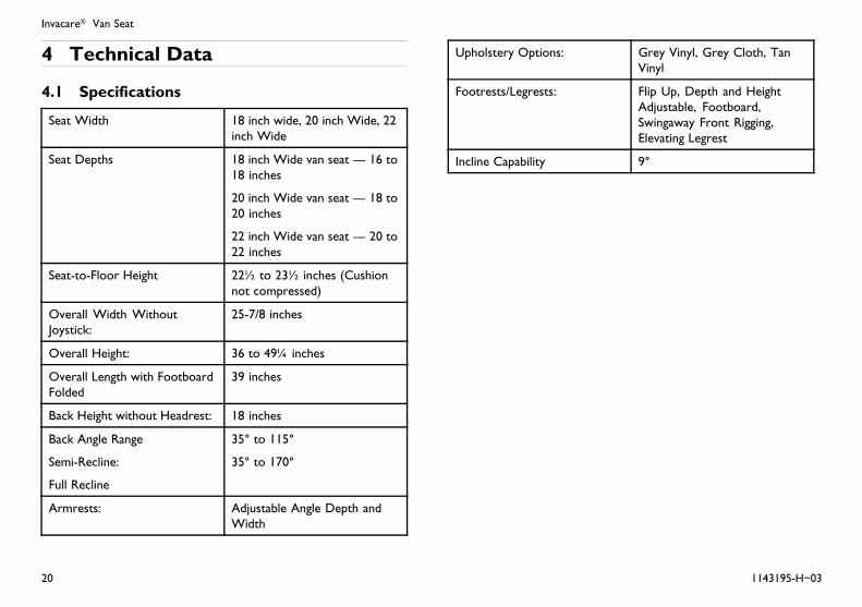
4 Technical Data
4.1 Specifications
Seat Width 18 inch wide, 20 inch Wide, 22inch Wide
Seat Depths 18 inch Wide van seat — 16 to18 inches
20 inch Wide van seat — 18 to20 inches
22 inch Wide van seat — 20 to22 inches
Seat-to-Floor Height 22½ to 23½ inches (Cushionnot compressed)
Overall Width WithoutJoystick:
25-7/8 inches
Overall Height: 36 to 49¼ inches
Overall Length with FootboardFolded
39 inches
Back Height without Headrest: 18 inches
Back Angle Range
Semi-Recline:
Full Recline
35° to 115°
35° to 170°
Armrests: Adjustable Angle Depth andWidth
Upholstery Options: Grey Vinyl, Grey Cloth, TanVinyl
Footrests/Legrests: Flip Up, Depth and HeightAdjustable, Footboard,Swingaway Front Rigging,Elevating Legrest
Incline Capability 9°
20 1143195-H~03
Usage
5 Usage
5.1 Operation Warnings
WARNING!– After ANY adjustments, repair or service and beforeuse, make sure that all attaching hardware is tightenedsecurely - otherwise injury or damage may result.
– Set-up of the Driver Control is to be performed onlyby a qualified technician. The final adjustments ofthe driver control may affect other activities of thewheelchair. Damage to the equipment could occurunder these circumstances.
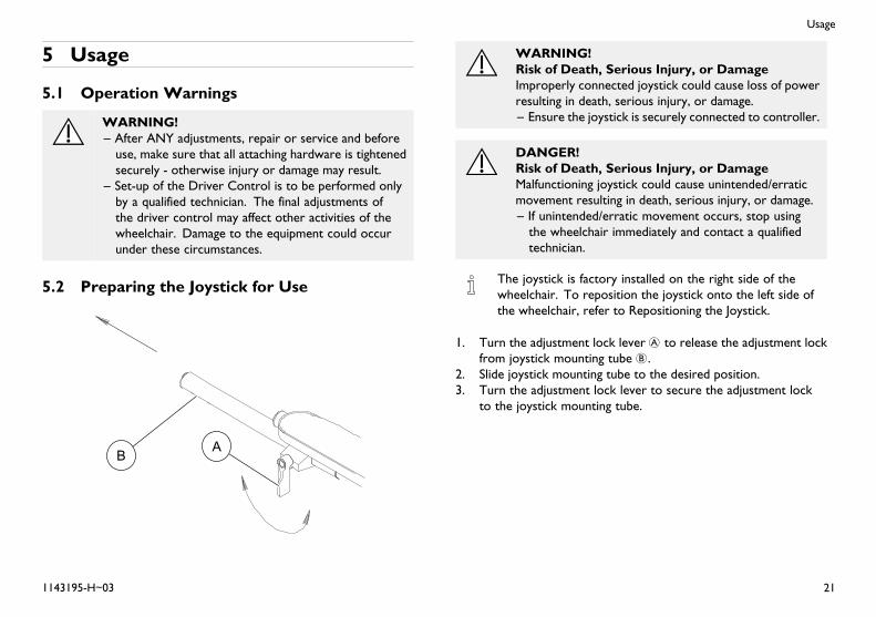
5.2 Preparing the Joystick for Use
WARNING!Risk of Death, Serious Injury, or DamageImproperly connected joystick could cause loss of powerresulting in death, serious injury, or damage.– Ensure the joystick is securely connected to controller.
DANGER!Risk of Death, Serious Injury, or DamageMalfunctioning joystick could cause unintended/erraticmovement resulting in death, serious injury, or damage.– If unintended/erratic movement occurs, stop usingthe wheelchair immediately and contact a qualifiedtechnician.
The joystick is factory installed on the right side of thewheelchair. To reposition the joystick onto the left side ofthe wheelchair, refer to Repositioning the Joystick.
1. Turn the adjustment lock lever A to release the adjustment lockfrom joystick mounting tube B.
2. Slide joystick mounting tube to the desired position.3. Turn the adjustment lock lever to secure the adjustment lock
to the joystick mounting tube.
1143195-H~03 21

Invacare® Van Seat
5.3 A Note About Drive Lock-Out
WARNING!Risk of Death or Serious InjuryOperating the wheelchair with the seattilted/reclined/back angle position beyond 20°can cause instability resulting in death or serious injuryfrom the wheelchair tipping over.– NEVER operate the wheelchair or elevate/lower theseat while in any tilted/reclined/back angle positionover 20° relative to the vertical position. If thedrive lock-out does not stop the wheelchair fromoperating or the seat from elevating/lowering ina tilt/recline/back angle position over 20° relativeto vertical, DO NOT operate the wheelchair orelevate/lower the seat. DO NOT attempt to adjustthe drive lock-out. Have the wheelchair serviced by aqualified technician.
– The wheelchair user MUST have a clear line of sightto drive safely. On initial chair delivery and afteradjusting the back angle, drive lock-out switch tiltsystem or recline system, tilt and recline the seat backto the farthest driving position IMMEDIATELY beforedrive lock-out engages and ensure there is a clear lineof sight present in which to drive the wheelchair. If aclear line of sight is not present, have the back anglerepositioned or readjust the lockout angle such thatsafe driving with a clear line of sight is achieved.
One of the following will occur when the drive lock-out feature hasbeen activated:
• CMPJ+ Joysticks Only - TILT WARNING or SPMController Inhibited displays on the joystick or display unit.
• SPJ+ Joysticks Only - Left to right chase alternating with a steadydisplay.
Drive lock-out is a feature designed to prevent the wheelchair frombeing driven after the seating system has been tilted beyond 20°*relative to the vertical position. The back can be positioned at a10° relative offset to the seat base, thereby resulting in a back anglepotential of 30° before which the drive lock-out is activated. Thismay affect the wheelchair user’s line of sight while driving. Make surethe wheelchair user can see properly to ensure safe driving.
*20° back angle can be any combination of recline, tilt, backangle and/or surface angle.
For tilt ranges, refer to Typical Product Parameters.
22 1143195-H~03
Usage
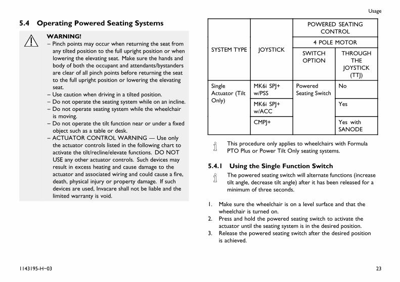
5.4 Operating Powered Seating Systems
WARNING!– Pinch points may occur when returning the seat fromany tilted position to the full upright position or whenlowering the elevating seat. Make sure the hands andbody of both the occupant and attendants/bystandersare clear of all pinch points before returning the seatto the full upright position or lowering the elevatingseat.
– Use caution when driving in a tilted position.– Do not operate the seating system while on an incline.– Do not operate seating system while the wheelchairis moving.
– Do not operate the tilt function near or under a fixedobject such as a table or desk.
– ACTUATOR CONTROL WARNING — Use onlythe actuator controls listed in the following chart toactivate the tilt/recline/elevate functions. DO NOTUSE any other actuator controls. Such devices mayresult in excess heating and cause damage to theactuator and associated wiring and could cause a fire,death, physical injury or property damage. If suchdevices are used, Invacare shall not be liable and thelimited warranty is void.
POWERED SEATINGCONTROL
4 POLE MOTORSYSTEM TYPE JOYSTICK
SWITCHOPTION
THROUGHTHE
JOYSTICK(TTJ)
MK6i SPJ+w/PSS
No
MK6i SPJ+w/ACC
Yes
SingleActuator (TiltOnly)
CMPJ+
PoweredSeating Switch
Yes withSANODE
This procedure only applies to wheelchairs with FormulaPTO Plus or Power Tilt Only seating systems.
5.4.1 Using the Single Function SwitchThe powered seating switch will alternate functions (increasetilt angle, decrease tilt angle) after it has been released for aminimum of three seconds.
1. Make sure the wheelchair is on a level surface and that thewheelchair is turned on.
2. Press and hold the powered seating switch to activate theactuator until the seating system is in the desired position.
3. Release the powered seating switch after the desired positionis achieved.
1143195-H~03 23
Invacare® Van Seat
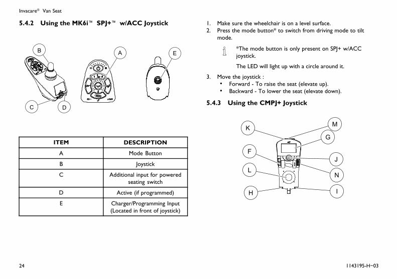
5.4.2 Using the MK6i™ SPJ+™ w/ACC Joystick
ITEM DESCRIPTION
A Mode Button
B Joystick
C Additional input for poweredseating switch
D Active (if programmed)
E Charger/Programming Input(Located in front of joystick)
1. Make sure the wheelchair is on a level surface.2. Press the mode button* to switch from driving mode to tilt
mode.
*The mode button is only present on SPJ+ w/ACCjoystick.
The LED will light up with a circle around it.
3. Move the joystick :• Forward - To raise the seat (elevate up).• Backward - To lower the seat (elevate down).
5.4.3 Using the CMPJ+ Joystick
24 1143195-H~03

Usage
Actuator Control SwitchMode Example Screen
Example screen duringpowered seating operation
ITEM DESCRIPTION ITEM DESCRIPTION
F Drive Select ToggleSwitch
M Memory Card Slot
G LCD Display N Speed Control Knob
H Programmable MonoPort 1/2 or ExternalMode Switch
O Elevate Down Icon
I Remote On/OffSwitch
P Operation Icons
J Mode Switch Q Icon
K Charger/Program-ming Input (LocatedFront of Joystick)
R Text
L Joystick
1. Make sure the wheelchair is on a level surface.
The drive select toggle switch is located on the left side,below the LCD display. The drive select position ismomentary, meaning that it will return to the neutralposition after a selection is made.
2. Select a drive that has the Actuator Control Switch Mode icondisplayed.
3. Select the Actuator Control Switch Mode icon.4. Four of the following icons will display when Actuator Control
Switch Mode is selected:
The location of the icons indicates the joystick directionor quadrant.
1143195-H~03 25
Invacare® Van Seat
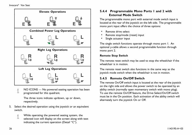
Elevate Operations
Combined Power Leg Operations
Right Leg Operations
Left Leg Operations
NO ICONS — No powered seating operation has beenprogrammed for this quadrant.
The three icons indicate up/down, up or down,respectively.
5. Select the desired operation using the joystick or an equivalentswitch.
While operating the powered seating system, theselected icon will display on the screen along with textindicating the current operation (Detail “C”).
5.4.4 Programmable Mono Ports 1 and 2 withExternal Mode Switch
The programmable mono port with external mode switch input islocated at the rear of the joystick on the left side. The programmablemono port input offers the choice of three options:
• Remote drive select• Remote stop/mode (reset) input• Single actuator input
The single switch functions operate through mono port 1. Anoptional y-cable allows a second programmable function throughmono port 2.
Remote Stop Switch
The remote reset switch may be used to stop the wheelchair if thewheelchair is in motion.
The remote reset switch also functions in the same way as thejoystick mode switch when the wheelchair is not in motion.
5.4.5 Remote On/Off SwitchThe remote On/Off switch input is located at the rear of the joystickon the right side and allows the power switch to be operated by anability switch (normally open momentary switch with mono plug).To use the remote On/Off feature, the Drive Select/On/Off switchmust be in the On position. Each activation of the ability switch willalternately turn the joystick On or Off.
26 1143195-H~03
Usage
5.4.6 Mode SwitchThe mode switch is used to select the operating mode for thewheelchair. The mode switch is located on the joystick. A modeswitch is needed whenever any of the following operating modesare programmed:
• Environmental Controls (ECU 1, ECU 2, ECU 3, ECU 4)*• 3 Speed Mode in Digital 3 Speed (Slow, Medium, Full)• Sleep Mode• RIM Mode*• Remote Drive Selection Mode*• Tilt/Recline Mode*• Information Center Display Selection (does not require Reset
activation at power up)
If any of the above modes are selected, the control will requireactivation of the switch immediately after the power switch is turnedOn in order to enter the drive mode. The second line of the LCDwill display - PRESS RESET.
*In these modes, Standby Select allows the reset switch tobe bypassed for users unable to activate the switch.
5.4.7 Memory Card SlotThe memory card slot is used with the basic or professional memorycard for saving or reading wheelchair parameters.
5.5 About Front Riggings
WARNING!Risk of Serious Injury or DamageOperating the wheelchair with a ground clearance ofless than 75 mm (3 inches) between the footplates andthe ground/floor may cause serious injury or propertydamage.– ALWAYS maintain a minimum of 75 mm (3inches) between the bottom of the footplates andground/floor to ensure proper ground clearance whilethe wheelchair is in motion. If necessary, adjust thefootplates height to achieve proper ground clearance.After footplates height adjustment, if the wheelchairdips forward and the footplates touch the groundwhile in motion, please contact your dealer for aninspection and avoid use of the wheelchair if possible.
WARNING!Risk of Injury or Damage– Using the footplates as a platform may cause injuryor damage
– DO NOT use the footplates/footboard as a platform.DO NOT stand on the footplates/footbaord. Whengetting in or out of the wheelchair, make sure thatthe footplates are in the upward position or swingfootrests towards the outside of the wheelchair.
1143195-H~03 27
Invacare® Van Seat
WARNING!– If the wheelchair is not moving, the front rigging mustmaintain a minimum of one inch ground clearance -otherwise personal injury and damage may result.
– PINCH POINT EXISTS BETWEEN CENTER MOUNTFOOTREST AND CASTERS - There is limitedclearance between center mount footrest and casters.The user’s feet MUST remain on the center mountfootrest while operating the wheelchair. If the user’sfeet are allowed to rest off the side of the centermount footrest they may come in contact with thecaster possibly resulting in injury.
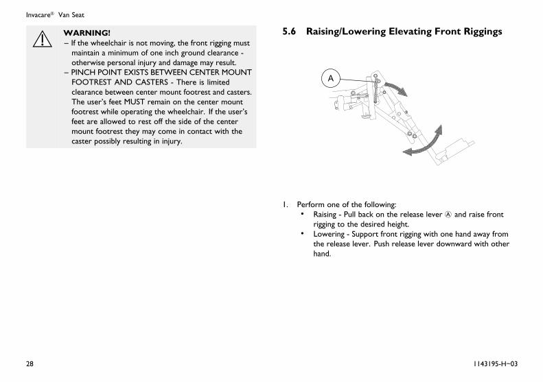
5.6 Raising/Lowering Elevating Front Riggings
1. Perform one of the following:• Raising - Pull back on the release lever A and raise front
rigging to the desired height.• Lowering - Support front rigging with one hand away from
the release lever. Push release lever downward with otherhand.
28 1143195-H~03
Usage
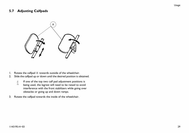
5.7 Adjusting Calfpads
1. Rotate the calfpad A towards outside of the wheelchair.2. Slide the calfpad up or down until the desired position is obtained.
If one of the top two calf pad adjustment positions isbeing used, the legrest will need to be raised to avoidinterference with the front stabilizers while going overobstacles or going up and down ramps.
3. Rotate the calfpad towards the inside of the wheelchair.
1143195-H~03 29
Invacare® Van Seat
6 Setup and Maintenance
6.1 Setup/Maintenance InformationSetup/delivery inspection should be performed by dealer attime of delivery/set up.
Initial adjustments should be made to suit your personalbody structure needs and preference. Thereafter weekly,monthly and periodic inspections should be performed byuser/attendant between the six month service inspections.
Regular cleaning will reveal loose or worn parts and enhancethe smooth operation of your wheelchair. To operateproperly and safely, your wheelchair MUST be cared for justlike any other vehicle. Routine maintenance will extend thelife and efficiency of your wheelchair.
Every six months, and as necessary, take your wheelchair toa qualified technician for a thorough inspection and servicing.
Refer to wheelchair base user manual for additional safetyinspection and troubleshooting information.
6.2 Setup/Delivery InspectionSetup/delivery inspection should be performed by dealer attime of delivery/set up.
Initial adjustments should be made to suit your personalbody structure needs and preference. Thereafter weekly,monthly and periodic inspections should be performed byuser/attendant between the six month service inspections.Refer to User/Attendant Inspection Checklists on page 31.
Every six months, and as necessary, take your wheelchair toa qualified technician for a thorough inspection and servicing.Refer to Service Inspection on page 31.
Refer to wheelchair base owner’s manual for additionalsafety inspection and troubleshooting information.
q Check all parts for shipping damage. In case of damage, DONOT use
q Ensure arms are secure but easy to release and adjustmentlevers engage properly.
q Adjustable height arms operate and lock securely.q Powered Seating Systems - Make sure all electrical connections
are secure.q Powered Seating Systems - Make sure drive lock-out operates
properly.q Check that cables are routed and secured properly to ensure
that cables do NOT become entangled and damaged duringnormal operation of seating system.
q Ensure proper operation of powered functions (Example:seating).
30 1143195-H~03

Setup and Maintenance
6.3 User/Attendant Inspection Checklists
– Every six months, and as necessary, take yourwheelchair to a qualified technician for a thoroughinspection and servicing. Service Inspection onpage 31.
– Weekly, monthly and periodic inspections should beperformed by user/attendant between the six monthservice inspections.
– Regular cleaning will reveal loose or worn parts andenhance the smooth operation of your wheelchair.To operate properly and safely, your wheelchair mustbe cared for just like any other vehicle. Routinemaintenance will extend the life and efficiency of yourwheelchair.
– Refer to wheelchair base owner’s manual for additionalsafety inspection and troubleshooting information.
CAUTION!– As with any vehicle, the wheels and tires should bechecked periodically for cracks and wear, and shouldbe replaced.
6.3.1 Inspect/Adjust Weeklyq Inspect all fasteners.q Ensure seat is secured to wheelchair frame.q Ensure seat and/or back upholstery have no rips and do not
sag. Replace if necessaryq Ensure arm pivot points are not worn and/or loose. Replace if
necessary.
6.3.2 Inspect/Adjust Monthlyq Clean upholstery and armrests.q Inspect seat positioning strap for any signs of wear. Ensure
buckle latches. Verify hardware that attaches strap to frame issecure and undamaged. Replace if necessary.
6.3.3 Inspect/Adjust Periodicallyq Inspect all fasteners.q Ensure arms are secure but easy to release and adjustment
levers engage properly.q Adjustable height arms operate and lock securely.q Ensure upholstery does not have any rips or tears.q Armrest pad sits flush against arm tube.q Check center mount front riggings for loose fasteners.
Replace/tighten if necessary.q Check that all labels are present and legible. Replace if necessary.q Make sure drive lock-out operates properly.
6.4 Service InspectionEvery six months take your wheelchair to a qualifiedtechnician for a thorough inspection and servicing.
Service inspections MUST be performed by a technician.
Refer to wheelchair base user manual for additional safetyinspection and troubleshooting information.
1143195-H~03 31
Invacare® Van Seat
DANGER!Risk of Death, Serious Injury, or DamageFailure to complete the inspection of the criticalcomponents listed below could result in death or seriousinjury.– Inspect stability control components which couldinclude anti-dive spring, anti-dive cylinder, ratchetinggears, or end stops to ensure proper operation.
– Inspect drive axle nut, locking tab, wheel fasteners orquick release to ensure drive wheel is secure
WARNING!– After ANY adjustments, repair or service and beforeuse, make sure that all attaching hardware is tightenedsecurely - otherwise injury or damage may result.
CAUTION!– As with any vehicle, the wheels and tires should bechecked periodically for cracks and wear, and shouldbe replaced.
The following are recommended items to inspect during regularservice inspections performed by a qualified technician. Actual itemsto be inspected during the service inspection may vary accordingto the specific wheelchair:
6.4.1 Six Month Inspectionq Clean upholstery and armrests.q Ensure arm pivot points are not worn and/or loose. Replace if
necessary.q Ensure seat and/or back upholstery have no rips and do not
sag. Replace if necessary.q Ensure seat release latch is functional.
q Ensure seat is secured to wheelchair frame.q Check that all labels are present and legible. Replace if necessary.q Ensure adjustable height arms operate and lock securely.q Ensure upholstery does not have any rips or tears.q Ensure armrest pad sits flush against arm tube.q Ensure arms are secure but easy to release and adjustment
levers engage properly.q Inspect seat positioning strap for any signs of wear. Ensure
buckle latches. Verify hardware that attaches strap to frame issecure and undamaged. Replace if necessary.
q Check center mount front riggings for loose fasteners.Replace/tighten if necessary.
q Check that cables are routed and secured properly to ensurethat cables do NOT become entangled and damaged duringnormal operation of seating system.
q Inspect electrical components for signs of corrosion. Replace ifcorroded or damaged.
q Inspect all fasteners.q Make sure drive lock-out operates properly.q Check limit switch position.
6.5 Troubleshooting
– For troubleshooting information and explanation oferror codes, refer to the wheelchair base user manualand the individual Electronics Manual supplied witheach wheelchair.
32 1143195-H~03

Setup and Maintenance
6.6 Installing/Removing Front Riggings
CAUTION!– If front riggings are used, then the seat MUST beadjusted to the highest mounting position - otherwisedamage may occur.
6.6.1 Installing Front Riggings
1. If necessary, remove the footboard. Refer to owner’s manualshipped with the wheelchair.
2. Turn front rigging A to the side (open footplate is perpendicularto wheelchair) and position mounting holes in the front rigginghinge plates B with hinge pins C on the wheelchair frame D.
3. Install the front rigging hinge plates onto the hinge pins on thewheelchair frame.
4. Push the front rigging towards the inside of the wheelchair untilit locks into place.
The footplate will be on the inside of the wheelchairwhen locked in place.
5. Repeat STEPS 1-4 for opposite side of wheelchair.
6.6.2 Removing Front Riggings
1. Push the front rigging release lever inward E and rotate thefootrest out.
2. Lift up on front rigging and remove from the wheelchair.3. Repeat STEPS 1-2 for opposite side of wheelchair.
6.7 Replacing Heel Loops
1143195-H~03 33
Invacare® Van Seat
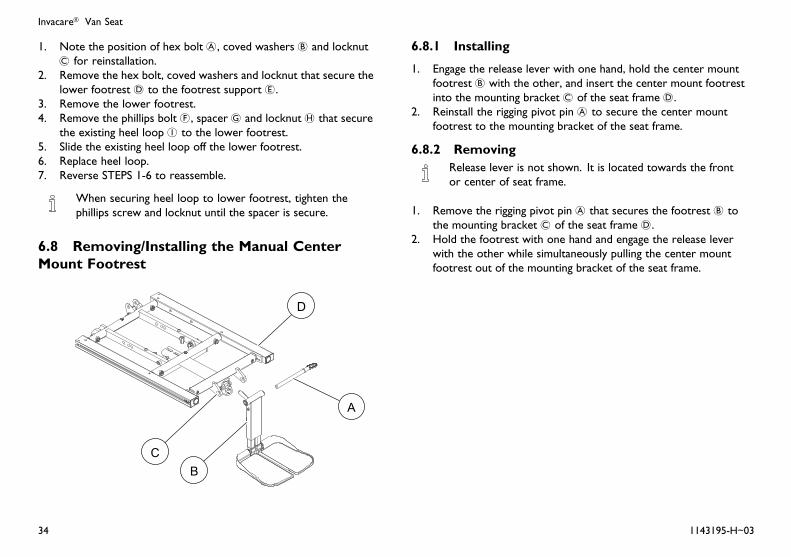
1. Note the position of hex bolt A, coved washers B and locknutC for reinstallation.
2. Remove the hex bolt, coved washers and locknut that secure thelower footrest D to the footrest support E.
3. Remove the lower footrest.4. Remove the phillips bolt F, spacer G and locknut H that secure
the existing heel loop I to the lower footrest.5. Slide the existing heel loop off the lower footrest.6. Replace heel loop.7. Reverse STEPS 1-6 to reassemble.
When securing heel loop to lower footrest, tighten thephillips screw and locknut until the spacer is secure.
6.8 Removing/Installing the Manual CenterMount Footrest
6.8.1 Installing
1. Engage the release lever with one hand, hold the center mountfootrest B with the other, and insert the center mount footrestinto the mounting bracket C of the seat frame D.
2. Reinstall the rigging pivot pin A to secure the center mountfootrest to the mounting bracket of the seat frame.
6.8.2 RemovingRelease lever is not shown. It is located towards the frontor center of seat frame.
1. Remove the rigging pivot pin A that secures the footrest B tothe mounting bracket C of the seat frame D.
2. Hold the footrest with one hand and engage the release leverwith the other while simultaneously pulling the center mountfootrest out of the mounting bracket of the seat frame.
34 1143195-H~03
Setup and Maintenance
6.9 Adjusting/Replacing Telescoping FrontRigging Supports
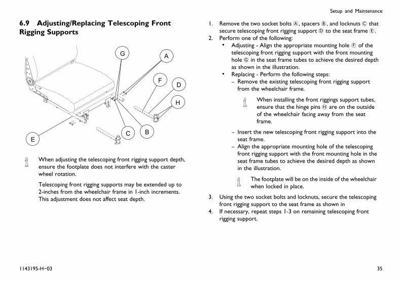
When adjusting the telescoping front rigging support depth,ensure the footplate does not interfere with the casterwheel rotation.
Telescoping front rigging supports may be extended up to2-inches from the wheelchair frame in 1-inch increments.This adjustment does not affect seat depth.
1. Remove the two socket bolts A, spacers B, and locknuts C thatsecure telescoping front rigging support D to the seat frame E.
2. Perform one of the following:• Adjusting - Align the appropriate mounting hole F of the
telescoping front rigging support with the front mountinghole G in the seat frame tubes to achieve the desired depthas shown in the illustration.
• Replacing - Perform the following steps:– Remove the existing telescoping front rigging supportfrom the wheelchair frame.
When installing the front riggings support tubes,ensure that the hinge pins H are on the outsideof the wheelchair facing away from the seatframe.
– Insert the new telescoping front rigging support into theseat frame.
– Align the appropriate mounting hole of the telescopingfront rigging support with the front mounting hole in theseat frame tubes to achieve the desired depth as shownin the illustration.
The footplate will be on the inside of the wheelchairwhen locked in place.
3. Using the two socket bolts and locknuts, secure the telescopingfront rigging support to the seat frame as shown in
4. If necessary, repeat steps 1-3 on remaining telescoping frontrigging support.
1143195-H~03 35
Invacare® Van Seat
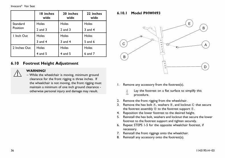
18 incheswide
20 incheswide
22 incheswide
StandardPosition
Holes
2 and 3
Holes
2 and 3
Holes
3 and 4
1 Inch Out Holes
3 and 4
Holes
3 and 4
Holes
5 and 6
2 Inches Out Holes
4 and 5
Holes
4 and 5
Holes
6 and 7
6.10 Footrest Height Adjustment
WARNING!– While the wheelchair is moving, minimum groundclearance for the front rigging is three inches. Ifthe wheelchair is not moving, the front rigging mustmaintain a minimum of one inch ground clearance -otherwise personal injury and damage may result.
6.10.1 Model PHWH93
1. Remove any accessory from the footrest(s).
Lay the footrest on a flat surface to simplify thisprocedure.
2. Remove the front rigging from the wheelchair.3. Remove the hex bolt A, washers B, and locknut C that secure
the footrest assembly D to the footrest support E.4. Reposition the lower footrest to the desired height.5. Reinstall the hex bolt, washers and locknut that secure the lower
footrest to the footrest support and tighten securely.6. Repeat STEPS 1-5 for the opposite wheelchair footrest, if
necessary.7. Reinstall the front riggings onto the wheelchair.8. Reinstall any accessory onto the footrest(s).
36 1143195-H~03
Setup and Maintenance
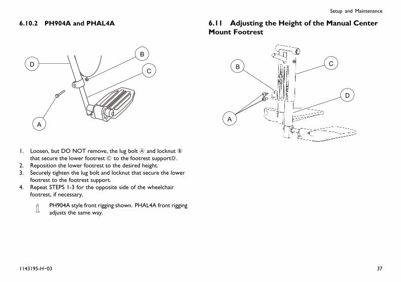
6.10.2 PH904A and PHAL4A
1. Loosen, but DO NOT remove, the lug bolt A and locknut Bthat secure the lower footrest C to the footrest supportD.
2. Reposition the lower footrest to the desired height.3. Securely tighten the lug bolt and locknut that secure the lower
footrest to the footrest support.4. Repeat STEPS 1-3 for the opposite side of the wheelchair
footrest, if necessary.
PH904A style front rigging shown. PHAL4A front riggingadjusts the same way.
6.11 Adjusting the Height of the Manual CenterMount Footrest
1143195-H~03 37
Invacare® Van Seat
WARNING!Risk of Serious Injury or DamageOperating the wheelchair with a ground clearance ofless than 75 mm (3 inches) between the footplates andthe ground/floor may cause serious injury or propertydamage.– ALWAYS maintain a minimum of 75 mm (3inches) between the bottom of the footplates andground/floor to ensure proper ground clearance whilethe wheelchair is in motion. If necessary, adjust thefootplates height to achieve proper ground clearance.After footplates height adjustment, if the wheelchairdips forward and the footplates touch the groundwhile in motion, please contact your dealer for aninspection and avoid use of the wheelchair if possible.
WARNING!– PINCH POINT EXISTS BETWEEN CENTER MOUNTFOOTREST AND CASTERS - There is limitedclearance between center mount footrest and csters.The user’s feet MUST remain on the center mountfootrest while operating the wheelchair. If the user’sfeet are allowed to rest off the side of the centermount footrest they may come in contact with thecaster possibly resulting in injury.
1. Remove the two mounting screws A that secure the buttonhead cleat B to the extension housing C.
2. Adjust the footrest extension tube D to the desired height.3. Secure the extension tube to the desired height with the button
head cleat and mounting screws. Securely tighten.4. Repeat steps 1-3 for the other extension tube.
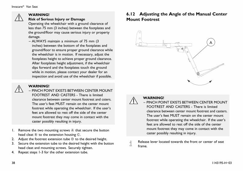
6.12 Adjusting the Angle of the Manual CenterMount Footrest
WARNING!– PINCH POINT EXISTS BETWEEN CENTER MOUNTFOOTREST AND CASTERS - There is limitedclearance between center mount footrest and casters.The user’s feet MUST remain on the center mountfootrest while operating the wheelchair. If the user’sfeet are allowed to rest off the side of the centermount footrest they may come in contact with thecaster possibly resulting in injury.
Release lever located towards the front or center of seatframe.
38 1143195-H~03

Setup and Maintenance
WARNING!Risk of Serious Injury or DamageOperating the wheelchair with a ground clearance ofless than 75 mm (3 inches) between the footplates andthe ground/floor may cause serious injury or propertydamage.– ALWAYS maintain a minimum of 75 mm (3inches) between the bottom of the footplates andground/floor to ensure proper ground clearance whilethe wheelchair is in motion. If necessary, adjust thefootplates height to achieve proper ground clearance.After footplates height adjustment, if the wheelchairdips forward and the footplates touch the groundwhile in motion, please contact your dealer for aninspection and avoid use of the wheelchair if possible.
1. Engage the release lever with one hand (not shown) and movethe center mount footrest A to the desired angle with the otherhand.
2. Disengage the release lever (not shown) to lock the centermount footrest in the new position.
6.13 Adjusting the Footplate Width of theCenter Mount Footrest
Narrow configuration shown (No Spacers)
1. Flip footplate A down2. Remove the mounting screw B, nylon washer C, washer D and
wave washer E securing the footplate to the extension tube Fof the center mount footrest G.
3. Reposition the four 1/4 inch spacers H between the footplateand washer as necessary to achieve the desired footplate width
4. Using the mounting screw, nylon washer, washer and wavewasher, secure the footplate to the extension tube.
5. Repeat STEPS 1 and 4 for the other footplate.
1143195-H~03 39
Invacare® Van Seat
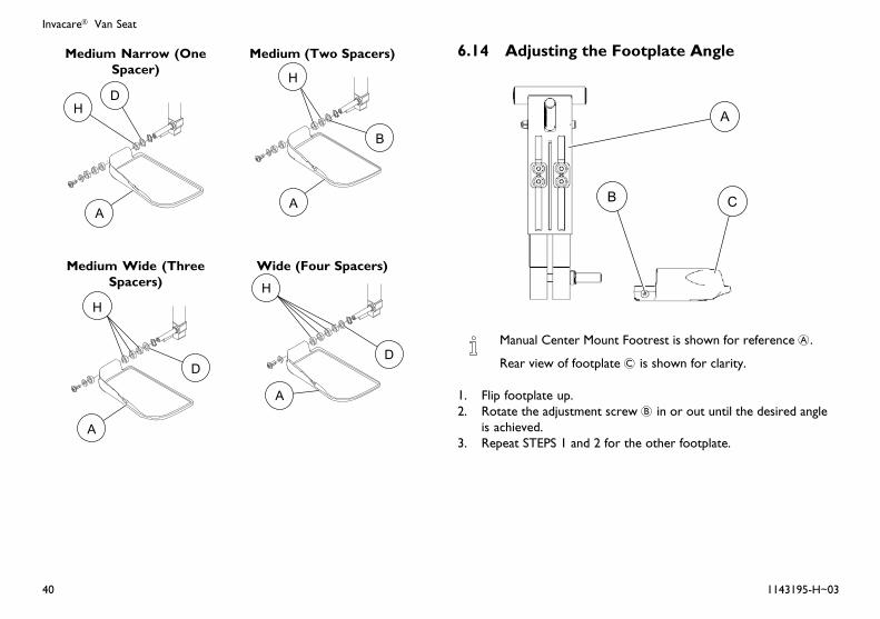
Medium Narrow (OneSpacer)
Medium (Two Spacers)
Medium Wide (ThreeSpacers)
Wide (Four Spacers)
6.14 Adjusting the Footplate Angle
Manual Center Mount Footrest is shown for reference A.
Rear view of footplate C is shown for clarity.
1. Flip footplate up.2. Rotate the adjustment screw B in or out until the desired angle
is achieved.3. Repeat STEPS 1 and 2 for the other footplate.
40 1143195-H~03

Setup and Maintenance
6.15 Adjusting the Tension of the Flip UpFootplate
The tension can be adjusted to increase or decrease therotation effort of the flip up footplates A.
1. Loosen the mounting screw B on the front rigging angle hinge todecrease the rotation effort.
DO NOT remove the footplate mounting screw.
2. Tighten the front rigging angle hinge mounting screw to increasethe rotation effort.
3. Repeat STEPS 1 and 2 for the other footplate.
6.16 Removing/Installing/Adjusting theAdjustable Heel Loop
If the user’s physical or medical condition and health careprovider allows, shoes should be worn when occupying thewheelchair.
6.16.1 Removing the Adjustable Heel Loop
1. Remove the mounting screw A, spacer B, washer C(not usedon deluxe flip up footplate) and cap nutD securing the adjustableheel loop E to the footplate F.
2. Pull to release the hook (G) and loop (H) strips securing theadjustable heel loop to the lower footrest tube (I).
3. Remove the adjustable heel loop from the front rigging.
1143195-H~03 41
Invacare® Van Seat
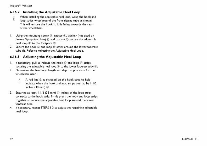
6.16.2 Installing the Adjustable Heel LoopWhen installing the adjustable heel loop, wrap the hook andloop strips wrap around the front rigging tube as shown.This will ensure the hook strip is facing towards the rearof the wheelchair.
1. Using the mounting screw A, spacer B, washer (not used ondeluxe flip up footplate) C and cap nut D secure the adjustableheel loop E to the footplate F.
2. Secure the hook G and loop H strips around the lower footresttube (I). Refer to Adjusting the Adjustable Heel Loop.
6.16.3 Adjusting the Adjustable Heel Loop
1. If necessary, pull to release the hook G and loop H stripssecuring the adjustable heel loopE to the lower footrest tubeI.
2. Determine the heel loop length and depth appropriate for thewheelchair user.
A red line J is included on the hook strip to helpindicate when the hook and loop strips overlap by 1-1/2inches (38 mm) K.
3. Ensuring at least 1-1/2 (38 mm) K inches of the loop stripconnects to the hook strip, firmly press the hook and loop stripstogether to secure the adjustable heel loop around the lowerfootrest tube.
4. If necessary, repeat STEPS 1-3 to adjust the remaining adjustableheel loop.
42 1143195-H~03
Setup and Maintenance
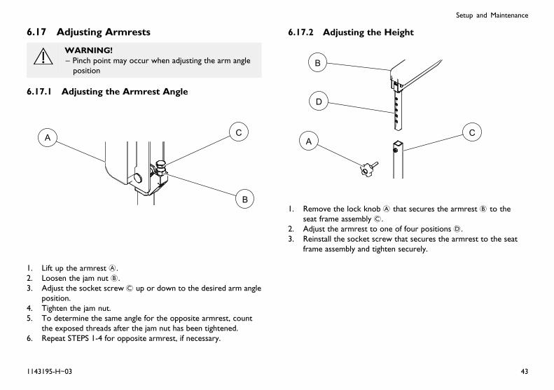
6.17 Adjusting Armrests
WARNING!– Pinch point may occur when adjusting the arm angleposition
6.17.1 Adjusting the Armrest Angle
1. Lift up the armrest A.2. Loosen the jam nut B.3. Adjust the socket screw C up or down to the desired arm angle
position.4. Tighten the jam nut.5. To determine the same angle for the opposite armrest, count
the exposed threads after the jam nut has been tightened.6. Repeat STEPS 1-4 for opposite armrest, if necessary.
6.17.2 Adjusting the Height
1. Remove the lock knob A that secures the armrest B to theseat frame assembly C.
2. Adjust the armrest to one of four positions D.3. Reinstall the socket screw that secures the armrest to the seat
frame assembly and tighten securely.
1143195-H~03 43
Invacare® Van Seat
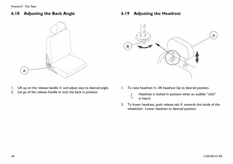
6.18 Adjusting the Back Angle
1. Lift up on the release handle A and adjust seat to desired angle.2. Let go of the release handle to lock the back in position.
6.19 Adjusting the Headrest
1. To raise headrest A, lift headrest Up to desired position.
Headrest is locked in position when an audible “click”is heard.
2. To lower headrest, push release tab B towards the inside of thewheelchair. Lower headrest to desired position.
44 1143195-H~03
Setup and Maintenance
6.20 Checking Seating System MountingPosition
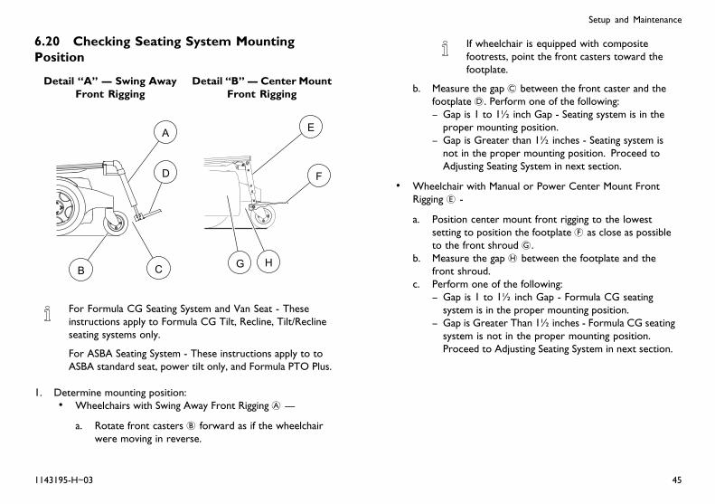
Detail “A” — Swing AwayFront Rigging
Detail “B”— Center MountFront Rigging
For Formula CG Seating System and Van Seat - Theseinstructions apply to Formula CG Tilt, Recline, Tilt/Reclineseating systems only.
For ASBA Seating System - These instructions apply to toASBA standard seat, power tilt only, and Formula PTO Plus.
1. Determine mounting position:• Wheelchairs with Swing Away Front Rigging A —
a. Rotate front casters B forward as if the wheelchairwere moving in reverse.
If wheelchair is equipped with compositefootrests, point the front casters toward thefootplate.
b. Measure the gap C between the front caster and thefootplate D. Perform one of the following:– Gap is 1 to 1½ inch Gap - Seating system is in theproper mounting position.
– Gap is Greater than 1½ inches - Seating system isnot in the proper mounting position. Proceed toAdjusting Seating System in next section.
• Wheelchair with Manual or Power Center Mount FrontRigging E -
a. Position center mount front rigging to the lowestsetting to position the footplate F as close as possibleto the front shroud G.
b. Measure the gap H between the footplate and thefront shroud.
c. Perform one of the following:– Gap is 1 to 1½ inch Gap - Formula CG seatingsystem is in the proper mounting position.
– Gap is Greater Than 1½ inches - Formula CG seatingsystem is not in the proper mounting position.Proceed to Adjusting Seating System in next section.
1143195-H~03 45

Invacare® Van Seat
6.21 Adjusting the Seating System MountingPosition
For Formula CG Seating System - Applies to Formula CGTilt, Recline or Tilt/Recline seating systems only.
For ASBA Seating System - Applies to ASBA standard seat,power tilt only, and Formula PTO Plus.
For Van Seat - These instructions apply to elevate powerseating (tilt elevate, tilt recline elevate, and elevate only)
1. Loosen, but DO NOT remove, the four hex screws A andlocknuts B securing the seat frame mounting bracket C to theinterface mounting bracket D.
2. Perform one of the following to ensure the Formula CG seatingsystem is in the proper mounting position:
Some front rigging and seat depth combinations may notallow for the 1-inch gap. In this situation, slide the seatframe mounting brackets as far back as possible.
• Wheelchairs with Swing Away Front Rigging - Slide the seatframe mounting brackets as far as possible towards therear of the wheelchair. Leave 1 to 1½-inch of clearancebetween the front riggings and the front casters in all casterpositions).
• Wheelchairs with Manual or Power Center Mount FrontRigging - Slide the seat frame mounting brackets as faras possible towards the rear of the wheelchair Leave 1to 1½-inch of clearance between the center mount frontriggings and the front shroud.
3. Ensure the interface mounting brackets and the seat framemounting brackets are flush and square.
4. Secure the seat frame mounting brackets to the interfacemounting plates. Torque the four hex bolts and locknuts to 13ft-lbs ± 20%.
5. Cycle the tilt and/or recline functions to verify wiring harnessesDO NOT obstruct the path of the system. If they do, performone of the following:• Wires were damaged during inspection - Replace damaged
wires.• Wires were not damaged during inspection - Cut tie-wraps
and relocate wires to a location where they will not becomedamaged.
46 1143195-H~03

Notes

USA One Invacare Way, Elyria, Ohio USA, 44036–2125, 800–333–6900
Canada 570 Matheson Blvd E Unit 8, Mississauga Ontario, L4Z 4G4 Canada, 800–668–5324
www.invacare.com
1143195-H~03 2016-4-22
*1143195H~03*Making Life’s Experiences Possible™