Embed Size (px)
Citation preview
EN
Yacht Sailing Hi Tech Parts www.aa-parts.com
TECHNICAL DOCUMENTATION
DRUM ASSEMBLY INSTRUCTIONS

ENG-DR-WINCH-01-01.04.2012.doc
The descriptions and illustrations in this document are not binding. We reserve the right to make changes at any time, without undertaking to update in this publication changes of components, parts or supplies that we believe are essential to improve the product cost, or for any other need. The partial reproduction and disclosure of this document, by whatever means, are not permitted without authorization. Violations will be prosecuted in the manner and time pre-scribed by law. All names and trademarks mentioned in this document are the property of their respective manufacturers.
Yacht Sailing Hi Tech Parts
Alberto Spada
Corso Sforza, 110 48010 Cotignola (Ra)
Italy
Tel. +39 0545 41550 Fax. +39 0545 1885119
www.aa-parts.com
SAIL WINCH SESAIL WINCH SESAIL WINCH SESAIL WINCH SERRRRVOVOVOVO
- 1 -
1 Contents
1 Contents_____________________ 1 2 Setting the Drum ______________ 1 2.1 Self Tensioning Drum___________ 1 2.2 Standard Drum________________ 1 2.3 Connection to compensation spring 2 2.4 Connection to Self Tensioning Drum 2 2.4.1 Drum tuning __________________ 2 2.4.2 Spring Choice _________________ 2 2.4.3 Use of Self Tensioning Drum _____ 3
2 Setting the Drum
The winch is sold as standard with the special Double System Drum™: a special drum which allows its use both as Self Tensioning Drum (drum which allows to tighten the winch pull sheet without compensation spring) and as Standard Drum (drum without self-tensioning springs).
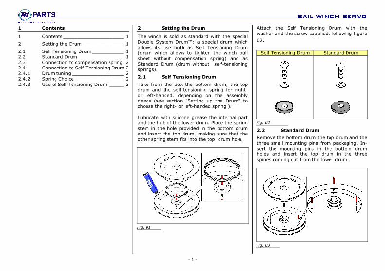
2.1 Self Tensioning Drum
Take from the box the bottom drum, the top drum and the self-tensioning spring for right- or left-handed, depending on the assembly needs (see section "Setting up the Drum" to choose the right- or left-handed spring ). Lubricate with silicone grease the internal part and the hub of the lower drum. Place the spring stem in the hole provided in the bottom drum and insert the top drum, making sure that the other spring stem fits into the top drum hole.
Fig. 01
Attach the Self Tensioning Drum with the washer and the screw supplied, following figure
02.
Self Tensioning Drum Standard Drum
Fig. 02
2.2 Standard Drum
Remove the bottom drum the top drum and the three small mounting pins from packaging. In-sert the mounting pins in the bottom drum holes and insert the top drum in the three spines coming out from the lower drum.
Fig. 03
SAIL WINCH SESAIL WINCH SESAIL WINCH SESAIL WINCH SERRRRVOVOVOVO
- 2 -
Fix the Standard Drum with the supplied washer and screw as shown in Figure 03.
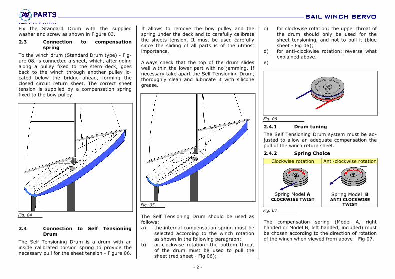
2.3 Connection to compensation
spring
To the winch drum (Standard Drum type) - Fig-ure 08, is connected a sheet, which, after going along a pulley fixed to the stern deck, goes back to the winch through another pulley lo-cated below the bridge ahead, forming the closed circuit return sheet. The correct sheet tension is supplied by a compensation spring fixed to the bow pulley.
Fig. 04
2.4 Connection to Self Tensioning
Drum
The Self Tensioning Drum is a drum with an inside calibrated torsion spring to provide the necessary pull for the sheet tension - Figure 06.
It allows to remove the bow pulley and the spring under the deck and to carefully calibrate the sheets tension. It must be used carefully since the sliding of all parts is of the utmost importance. Always check that the top of the drum slides well within the lower part with no jamming. If necessary take apart the Self Tensioning Drum, thoroughly clean and lubricate it with silicone grease.
Fig. 05
The Self Tensioning Drum should be used as follows: a) the internal compensation spring must be
selected according to the winch rotation as shown in the following paragraph;
b) or clockwise rotation: the bottom throat of the drum must be used to pull the sheet (red sheet - Fig 06);
c) for clockwise rotation: the upper throat of the drum should only be used for the sheet tensioning, and not to pull it (blue sheet - Fig 06);
d) for anti-clockwise rotation: reverse what explained above.
e)
Fig. 06
2.4.1 Drum tuning
The Self Tensioning Drum system must be ad-justed to allow an adequate compensation the pull of the winch return sheet.
2.4.2 Spring Choice
Clockwise rotation Anti-clockwise rotation
Spring Model A
CLOCKWISE TWIST
Spring Model B ANTI CLOCKWISE
TWIST
Fig. 07
The compensation spring (Model A, right handed or Model B, left handed, included) must be chosen according to the direction of rotation of the winch when viewed from above - Fig 07.
SAIL WINCH SESAIL WINCH SESAIL WINCH SESAIL WINCH SERRRRVOVOVOVO
- 3 -
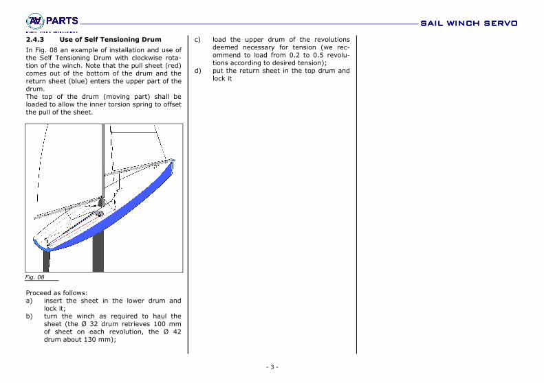
2.4.3 Use of Self Tensioning Drum
In Fig. 08 an example of installation and use of the Self Tensioning Drum with clockwise rota-tion of the winch. Note that the pull sheet (red) comes out of the bottom of the drum and the return sheet (blue) enters the upper part of the drum. The top of the drum (moving part) shall be loaded to allow the inner torsion spring to offset the pull of the sheet.
Fig. 08
Proceed as follows: a) insert the sheet in the lower drum and
lock it; b) turn the winch as required to haul the
sheet (the Ø 32 drum retrieves 100 mm of sheet on each revolution, the Ø 42 drum about 130 mm);
c) load the upper drum of the revolutions deemed necessary for tension (we rec-ommend to load from 0.2 to 0.5 revolu-tions according to desired tension);
d) put the return sheet in the top drum and lock it

Yacht Sailing Hi Tech Parts
Alberto Spada
Corso Sforza, 110 48010 Cotignola (Ra)
Italy
Tel. +39 0545 41550 Fax. +39 0545 1885119
www.aa-parts.com
Printed in Italy.


![Corde - Selleria Gianetti...Corde Cod. 2 Bianco [Ø 6 mm e 3 mm] 33 Rosa pastello [Ø 6 mm] 34 Rosa [Ø 6 mm] 3 Beige [Ø 6 mm e 3 mm] 35 Giallo [Ø 6 mm] 37 Giallo frumento [Ø 6](https://img.pdfslide.net/doc/110x75/611a17edad86063fbb0bf90b/corde-selleria-gianetti-corde-cod-2-bianco-6-mm-e-3-mm-33-rosa-pastello.jpg)