Embed Size (px)
Citation preview

GSV5Installation instructions
1
The device must be installed in a place with limited access.
Please act according to your local rules and do not dispose of your unusable alarm system or its components with other household waste. This product utilization in EU is covered by European Directive 2002/96/EC.
The device must be connected to an AC power supply with Protective Earthing. Cable colours mean: Phase or Live line (L) - black or brown cable, Neutral line (N) - blue cable, Protective Earth line (PE) - green cable with a vertical yellow dash. Double isolated
2cables with minimum cross-sectional area of 0,75 mm for 230V power supply must be used.
The device uses two power supplies: main and back-up.
2V, 7Ah/20HR capacity, rechargeable hermetically sealed Lead-Acid battery.
Main power supply: a power transformer with: - primary winding: ~230V, 50 Hz; - secondary winding: ~20V, 1.5A, 50Hz.Back-up power supply: 1
GSV5 is compliant with EN 60950-1 safety requirements.Power supplies described above must comply with the EN 60950-1 safety requirements.All devices being connected with the alarm system (sirens, detectors, computer for programming and etc.) must comply with EN 60950-1 safety requirements.The communicator contains a radio transceiver operating within GSM900/1800 frequency ranges.DO NOT USE the communicator where interferences can arise because of the influence with other devices and this may cause the potential danger.DO NOT USE the communicator close to medical devices. DO NOT USE the alarm system device in a dangerous environment with the risk of fire and explosion.
Additional automatic Two-Pole Circuit Breaker should be installed in an AC electric power circuit in order to protect against over-current, short circuits and earthing faults.The circuit breaker contact gap should be no less than 3mm, protective circuit breaker current must be in 0,5A - 2A range .The circuit breaker should be placed close to the system's housing and should be easily accessed.
Before performing any work of installation or service always disconnect the device from power supplies in sequence as described below: - cut off 230 V AC power line with the automatic Two-pole Circuit Breaker; - disconnect 12V back-up battery by removing battery female plug from Control Panel male socket BAT.Two-pole Circuit-Beaker installation on flexible cables is forbidden.
General safety requirements: - do not touch any part of the main power supply under voltage: transformer, a fuse block, connection wires; - it is forbidden to perform any device installation or service work during lightning; - use batteries according to manufacturer recommendations. The use of improper battery type may cause an explosion; - be sure battery terminals are isolated, battery terminals short-wiring may cause an explosion. battery replacement :
It is not recommended to connect the device to a fully discharged battery.
Inoperative or expired batteries should be recycled according to the local rules or EU directives 2006/66/EC and 93/86/EEC. Collection and separate utilization of waste battery is mandatory!
To avoid system malfunction use an adequate charger to charge a new or discharged battery before connecting battery to the device.
The connection to the mains supply must be made as per the local authorities rules and regulations. The end of a stranded conductor shall not be consolidated by soft-soldering, insulated pins shall be used. Insulated pins shall be connected in a manner that they are and with remain mechanically efficient.
Power supply distribution board
Automatic two-pole circuit breaker
L N
NL
Cable from power distribution board
Power cable to the cabinet
The device installation and service should be performed by trained personnel with sufficient knowledge about the device and general safety requirements for work with low voltage (up to 1000V) AC power lines. In the case of a device malfunction repair works can be performed by qualified personnel only. If the system is malfunctioning, the end user should inform the qualified personnel as soon as possible. User doesn't have right to repair the system.
GSV5, installed in the metal cabinet (device)
Picture 1. Automatic two-pole circuit breaker and power cable wiring diagram
Universal GSM / GPRS communicator communicatorcomes with in-built LED indicator. LED blinks when is powered up.
SAFETY WARNINGS
GSV5 communicator

GSV5 – GSM/GPRS communicator is designed to be used in objects along with other manufacturers' intruder alarm systems. It expands the functionality of other manufacturers’ intruder alarm systems by giving options to report to the receiver of Central Monitoring Station via GPRS, to send a notification via SMS or via phone call. If there is a need to control the alarm system via mobile phone, it can be done by managing the control panel via GSV5 PGM outputs, by sending control commands to the control panel's KEYBUS or interfacing with a control panel via SERIAL port.
The GSV5 can be connected to other manufacturers’ alarm systems in a few different ways:
Connection to the control panel’s PSTN communicator;
Connection to the control panel’s KEYBUS;
Connection to the control panel’s SERIAL port;
Connection to the control panel’s zones/PGM outputs.
GSV5 communicator
Wiring diagram
GSV5Installation instructions
2
Groundingplace Grounding place
ProtectiveEarth wire
PE
Main Protective Earthing terminal
Grounding
12V battery7Ah/20HR
Line wire
L
Neutral wireN
ProtectiveEarth wire
PE
Main Protective Earthing terminal
AC power transformer:Primary winding: 230V AC 50HzSecondary winding: 20V AC 50Hz
~~
Power suply distribution board
Fuse250mA
Powering from an independent AC power supply with a battery backup
Note: the communicator and an independent power source, consisting of a fuse, AC power transformer, 12V 7Ah/20HR rechargeable battery, must be placed in an grounded cabinet.
+12VCOM
Powering from any +12V power supply
If there is no need for the communicator to be powered from an independent power supply, the communicator can be powered from any +12V DC power supply, eg., from the control panel's power supply +AUX.
Note: if the communicator’s PGM output is used to control the relay, use an extra +12V DC power supply to power it (relay). Maximum current must not exceed 50 mA.
GSV5
S1
+1
2V
RIN
G
CO
M
IN1
IN3
IN4
IN5
/CL
KIN
6/D
AT
20
VA
C
PG
M1
PG
M2
TIP
IN2
Connecting to the control panel’s SERIAL interface
SE
RIA
L
Compatible control panels: SP4xxx SP6xxx SP7xxx MG5xxx EVOxxx
Connecting to the control panel’s PSTN communicator
Control panel’s PSTN communicator settings:
Reporting: Enabled;
Protocol: Contact ID;
Phone number for connection: 12345;
Dial tone check: Off;
Telephone line monitoring: Off.
CO
M
IN1
NO
Normally open contact(NO)
CO
M
IN1
NC
Normally closed contact(NC)
Status LED
Modem LED
Connecting to the control panel’s data bus – KEYBUS
YEL
Compatible control panels: PC5xx PC15xx PC14xx PC16xx PC18xx
Attention! If the GSV5 is powered from an independent power supply it is necessary to make a common ground (COM).
GRN
COM
GRNCO
MYEL
Control panel
RINGTIP
RING
TIP
Control panel
Connecting to the control panel’s zones / PGM output terminals
If the alarm system does not have a PSTN communicator, information about the system status can pass through the control panel’s PGM outputs. When PGM output status changes (is turned on/off) the GSV5 communicator can detect it at its inputs and send the report to the monitoring station and/or send a notification to the user's mobile phone (SMS, call).
If there is a need to control the system by a mobile phone, it can be done by managing the control panel through the GSV5 PGM outputs. Control panel can detect the change of the PGM output’s status (turned on/off) by its zone inputs and perform the assigned function (eg., to arm or disarm the system or to clear alarm).
Note: the wiring diagram shows the connection between PGM output and zone when the PGM output is an open collector type. If the PGM output type is different, use the relays. A parallel connection of the diode to the relay is recommended to suppress voltage surges on relay.
Alarm
Control
COM
CO
MP
GM
1
+1
2V
CO
M
CO
MZ
1
COM PGM1 Z1 COM COM +12V
S1
+1
2V
RIN
G
CO
M
IN1
IN3
IN4
IN5
/CL
KIN
6/D
AT
20
VA
C
PG
M1
PG
M2
TIP
IN2
Mode LED
Control panelGSV5
Control panel
LED indication
Status LED: Off – failed to establish a connection with the GSM network; 1 blink – GSM signal strength: ; 2 blinks – GSM signal strength: ; 3 blinks – GSM signal strength: ; 4 blinks – GSM signal strength: ; 5 blinks – GSM signal strength: ; On (2 sec.) – received report (from the PSTN communicator, SERIAL or KEYBUS), triggered GSV5 input.
Modem LED: Off – modem malfunction or trouble; Blinks (every 0,5 sec.) – failed to establish a connection with GSM network; Short blink every 2 sec. – the connection with GSM network successfully esta-blished; On – ongoing "conversation" with the device or a data sending is in progress.
GSV5 communicator

GSV5Installation instructions
GSV5 Loader software
GSM/GPRS communicator - select this operating mode, if the GSV5 is connected to the control panel’s PSTN communicator or to the control panel’s zones / PGM outputs. KEYBUS compatible - select this operating mode, if the GSV5 is connected to the control panel's KEYBUS. SERIAL port compatible - select this operating mode, if the GSV5 is connected to the central panel’s SERIAL port.
User phone numbers - at this setup window are entered the user phone numbers to which the GSV5 calls or sends SMS in case of alarm, arming or disarming and etc. User phone numbers must be entered with an international code, the plus sign "+" is entered automatically, there is no need to enter it additionally. If there is a need to control the GSV5 communicator or control the intruder alarm system, then it is necessary to know the access PIN code. This PIN code depends on the selected operating mode :
GSV5 settings are divided into categories (5). Note: the entered phone number, checked checkbox and etc. are automatically saved in the software cache memory. Do not forget to send them into GSV5 after you end the programming. To do this press Send settings to GSV5 (6).
After selecting the proper GSV5 operating mode press the button Start programming (4).
if the GSV5 operating mode is GSM/GPRS communicator, then user should use a common PIN code (7). By default this PIN is 1111; if the GSV5 operating mode is KEYBUS compatible, then the user has to use the same PIN code as the one that is used to control their intruder alarm system. if the GSV5 operating mode is SERIAL port compatible, then the user has to use the same PIN code as the one that is used to control their intruder alarm system. Note: in order to establish the connection between intruder alarm system and GSV5 via SERIAL port, it is necessary to program PC password. This 4-digit password identifies the GSV5 to the panel before establishing communication. Program the same PC Password into both the control panel and the GSV5 (8). If the passwords do not match, the GSV5 will not establish communication and the control will not be available. The password must be entered in control panel section [911] or [3012].
Reporting to CMS receiver - at this setup window it is possible to program the settings which are related to the reporting to IP receiver (9) of a Central Monitoring Station (CMS). Reports to the monitoring station are sent via GPRS, so it is necessary to have a suitable SIM card with a correctly entered data in the APN, APN user name and password fields (10). Use one of three available protocols (11) to report to central monitoring station.
Inputs - at this setup window communicator's inputs are programmed. It is possible to assign a certain reporting event (12) or a text (13) to the input.
To program the communicator GSV5, connect it to your computer by using an USB connection. Run the software GSV5 Loader and wait until the software will automatically download the necessary data from GSV5.
Before you start the GSV5 programming, set the GSV5 Loader’s interface language (1). The software interface language must match with the language of voice messages (2) pre-installed in GSV5 at factory. After that select the proper GSV5 operating mode (3). The GSV5 functionality directly depends on the selected operating mode:
GSV5 communicator
3
2
3
4
1 5
6
7
8
9
10
11
PGM Outputs - at this setup window GSV5 outputs are programmed. Output can be turned On / Off with a DTMF command during the call or can be controlled with SMS command. The control command depends on the selected PGM output function (14):
Manual - call command: 61# or 62#; SMS command: O1 or O2 (example: 1234 O1); Arm - call command: 1#; SMS command: A (example: 1234 A); Disarm - call command: 0#; SMS command: D (example: 1234 D); Clear alarm - call command: 00#; SMS command: C (example: 1234 C);
12
13
GSV5
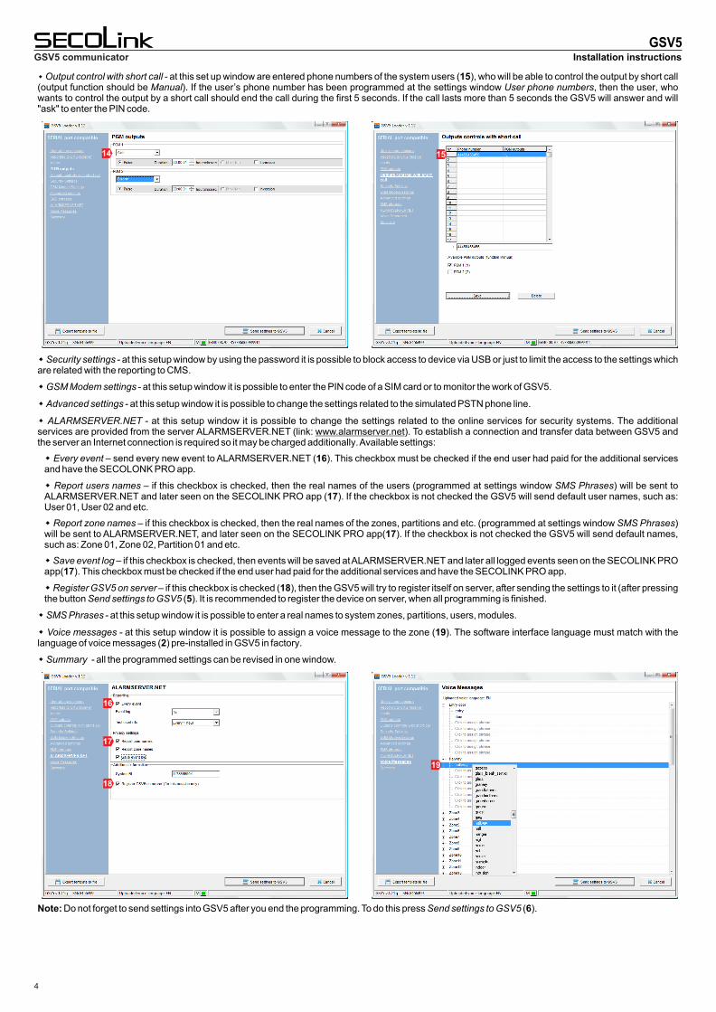
Output control with short call - at this set up window are entered phone numbers of the system users (15), who will be able to control the output by short call (output function should be Manual). If the user’s phone number has been programmed at the settings window User phone numbers, then the user, who wants to control the output by a short call should end the call during the first 5 seconds. If the call lasts more than 5 seconds the GSV5 will answer and will "ask" to enter the PIN code.
Security settings - at this setup window by using the password it is possible to block access to device via USB or just to limit the access to the settings which are related with the reporting to CMS.
GSM Modem settings - at this setup window it is possible to enter the PIN code of a SIM card or to monitor the work of GSV5.
Advanced settings - at this setup window it is possible to change the settings related to the simulated PSTN phone line.
Every event – send every new event to ALARMSERVER.NET (16). This checkbox must be checked if the end user had paid for the additional services and have the SECOLONK PRO app.
Report users names – if this checkbox is checked, then the real names of the users (programmed at settings window SMS Phrases) will be sent to ALARMSERVER.NET and later seen on the SECOLINK PRO app (17). If the checkbox is not checked the GSV5 will send default user names, such as: User 01, User 02 and etc.
Report zone names – if this checkbox is checked, then the real names of the zones, partitions and etc. (programmed at settings window SMS Phrases) will be sent to ALARMSERVER.NET, and later seen on the SECOLINK PRO app(17). If the checkbox is not checked the GSV5 will send default names, such as: Zone 01, Zone 02, Partition 01 and etc.
Save event log – if this checkbox is checked, then events will be saved at ALARMSERVER.NET and later all logged events seen on the SECOLINK PRO app(17). This checkbox must be checked if the end user had paid for the additional services and have the SECOLINK PRO app.
Register GSV5 on server – if this checkbox is checked (18), then the GSV5 will try to register itself on server, after sending the settings to it (after pressing the button Send settings to GSV5 (5). It is recommended to register the device on server, when all programming is finished.
SMS Phrases - at this setup window it is possible to enter a real names to system zones, partitions, users, modules.
Voice messages - at this setup window it is possible to assign a voice message to the zone (19). The software interface language must match with the language of voice messages (2) pre-installed in GSV5 in factory.
Summary - all the programmed settings can be revised in one window.
Installation instructionsGSV5 communicator
4
14 15
ALARMSERVER.NET - at this setup window it is possible to change the settings related to the online services for security systems. The additional services are provided from the server ALARMSERVER.NET (link: www.alarmserver.net). To establish a connection and transfer data between GSV5 and the server an Internet connection is required so it may be charged additionally. Available settings:
16
17
18
19
Note: Do not forget to send settings into GSV5 after you end the programming. To do this press Send settings to GSV5 (6).