Embed Size (px)
Citation preview
®
2
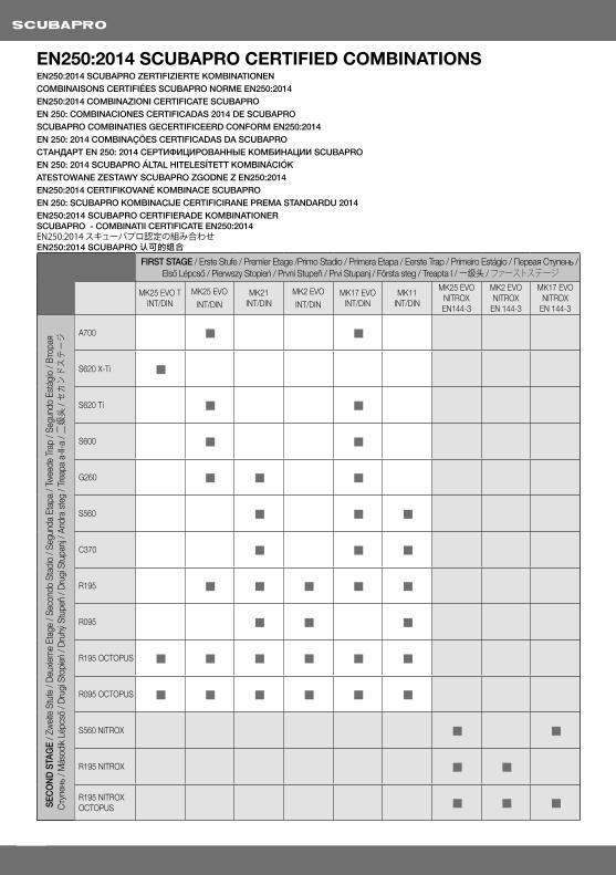
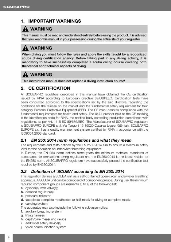
EN250:2014 SCUBAPRO CERTIFIED COMBINATIONSEN250:2014 SCUBAPRO ZERTIFIZIERTE KOMBINATIONENCOMBINAISONS CERTIFIÉES SCUBAPRO NORME EN250:2014 EN250:2014 COMBINAZIONI CERTIFICATE SCUBAPRO EN 250: COMBINACIONES CERTIFICADAS 2014 DE SCUBAPROSCUBAPRO COMBINATIES GECERTIFICEERD CONFORM EN250:2014EN 250: 2014 COMBINAÇÕES CERTIFICADAS DA SCUBAPROСТАНДАРТ EN 250: 2014 СЕРТИФИЦИРОВАННЫЕ КОМБИНАЦИИ SCUBAPROEN 250: 2014 SCUBAPRO ÁLTAL HITELESÍTETT KOMBINÁCIÓKATESTOWANE ZESTAWY SCUBAPRO ZGODNE Z EN250:2014EN250:2014 CERTIFIKOVANÉ KOMBINACE SCUBAPROEN 250: SCUBAPRO KOMBINACIJE CERTIFICIRANE PREMA STANDARDU 2014EN250:2014 SCUBAPRO CERTIFIERADE KOMBINATIONERSCUBAPRO - COMBINATII CERTIFICATE EN250:2014EN250:2014 スキューバプロ認定の組み合わせEN250:2014 SCUBAPRO 认可的组合
FIRST STAGE / Erste Stufe / Premier Etage /Primo Stadio / Primera Etapa / Eerste Trap / Primeiro Estágio / Первая Ступень / Első Lépcső / Pierwszy Stopień / První Stupeň / Prvi Stupanj / Första steg / Treapta I / 一级头 / ファーストステージ
MK25 EVO T INT/DIN
MK25 EVO
INT/DINMK21
INT/DINMK2 EVO
INT/DINMK17 EVO
INT/DINMK11
INT/DIN
MK25 EVO NITROX EN144-3
MK2 EVO NITROX
EN 144-3
MK17 EVO NITROX
EN 144-3
SEC
ON
D S
TAG
E / Z
wei
te S
tufe
/ D
euxie
me
Etag
e / S
econ
do S
tadi
o / S
egun
da E
tapa
/ Tw
eede
Tra
p / S
egun
do E
stág
io /
Вто
рая
Сту
пень
/ M
ásod
ik L
épcs
ő / D
rugi
Sto
pień
/ D
ruhý
Stu
peň
/ Dru
gi S
tupa
nj /
Andr
a st
eg /
Trea
pa a
-II-a
/ 二
级头
/ セ
カン
ドス
テー
ジ A700 g g
S620 X-Ti g
S620 Ti g g
S600 g g
G260 g g g
S560 g g g
C370 g g g
R195 g g g g g
R095 g g g
R195 OCTOPUS g g g g g g
R095 OCTOPUS g g g g g g
S560 NITROX g g
R195 NITROX g g
R195 NITROX OCTOPUS g g g
3
SCUBAPRO REGULATORS MANUALCongratulations on purchasing a SCUBAPRO regulator and welcome to SCUBAPRO. We are confident that you will enjoy extraordinary performance from our regulator, designed and manufactured using the most advanced technology.
We thank you for choosing SCUBAPRO and wish you a future of safe dives and underwater enjoyment!
TABLE OF CONTENTS
1. IMPORTANT WARNINGS 4
2. CE CERTIFICATION 4
2.1 EN 250: 2014 norm regulations and what they mean 42.2 Definition of ‘SCUBA’ according to EN 250: 2014 42.3 Limitations provided by EN 250: 2014 5
3. IMPORTANT WARNING REMINDERS 5
4. REGULATOR SYSTEM 6
4.1 First stage 64.2 Second stage 64.3 Octopus (Emergency auxiliary breathing device) 7
5. TECHNICAL FEATURES 7
5.1 First Stages 75.2 Second Stages 95.3 First and second stage features 10
6. PREPARING FOR USE 12
6.1 Set-up/in-use warning 12
7. EQUIPMENT USE 13
7.1 Second stages with Venturi effect (V.I.V.A.) adjustment 137.2 Cold water use 147.3 Post dive 15
8. EQUIPMENT CARE AND MAINTENANCE 15
8.1 Care 158.2 Maintenance 16
9. NITROX 16
9.1 Main features of Nitrox dedicated regulators 179.2 Use and maintenance notes 17
10. TROUBLESHOOTING 19
Engl
ish
4
1. IMPORTANT WARNINGS
! WARNING This manual must be read and understood entirely before using the product. It is advised that you keep this manual in your possession during the entire life of your regulator.
! WARNING When diving you must follow the rules and apply the skills taught by a recognized scuba diving certification agency. Before taking part in any diving activity, it is mandatory to have successfully completed a scuba diving course covering both theoretical and technical aspects of diving.
! WARNING This instruction manual does not replace a diving instruction course!
2. CE CERTIFICATIONAll SCUBAPRO regulators described in this manual have obtained the CE certification issued by RINA according to European directive 89/686/EEC. Certification tests have been conducted according to the specifications set by the said directive, regulating the conditions for the release on the market and the fundamental safety requirement for third category Personal Protective Equipment (PPE). The CE mark denotes compliance with the fundamental requirements for health and safety. The 0474 number next to the CE marking is the identification code for RINA, the notified body controlling production compliance with regulations, as per Art. 11 B ED 89/686/EEC. The Manufacturer of SCUBAPRO regulators is SCUBAPRO EUROPE s.r.l. Via Tangoni 16 16030 Casarza Ligure (GE) Italy. SCUBAPRO EUROPE s.r.l. has a quality management system certified by RINA in accordance with the ISO9001:2008 standard.
2.1 EN 250: 2014 norm regulations and what they mean The requirements and tests defined by the EN 250: 2014 aim to ensure a minimum safety level for the operation of underwater breathing equipment. In Europe, the EN 250 norm defines since years the minimum technical standards of acceptance for recreational diving regulators and the EN250:2014 is the latest revision of the EN250 norm. All SCUBAPRO regulators have successfully passed the certification test required by EN250:2014.
2.2 Definitionof‘SCUBA’accordingtoEN250:2014This regulation defines a SCUBA unit as a self-contained open-circuit underwater breathing apparatus. A SCUBA unit can be composed of component groups. During use, the minimum required component groups are elements a) to e) of the following list:a. cylinder(s) with valve(s);b. demand regulator(s);c. pressure indicatord. facepiece: complete mouthpiece or half-mask for diving or complete mask;e. carrying system.The apparatus may also include the following sub-assemblies:f. auxiliary breathing systemg. lifting harnessh. depth/time measuring devicei. additional safety device(s)j. voice communication system
5
Engl
ish
2.3 Limitations provided by EN 250: 2014The SCUBA unit can be comprised of separate components such as: cylinder(s), regulator(s), pressure gauge. The SCUBAPRO regulators described in this manual can be used with SCUBA components units certified according to directive 89/686/EEC and EN 250: 2014 norm. The air contained in the cylinders must be compliant with the requirements for breathable air set forth in EN 12021. The certification depth is 50 meters (164 ft). In any event, divers must always abide by the limits set by local regulations in the dive location.
! WARNING If a SCUBA is configured for and used by more than one diver at the same time, then it shall not be used at depths greater than 30 meters and in water temperature less than 4°C if marked “EN250A” ,and less than 10°C If marked with “EN250A>10°C”
! WARNING Only SCUBA complying with EN250:2014 and marked “EN250A” or “EN250A>10°C” may be used as an escape device by more than one diver at the same time
3. IMPORTANT WARNING REMINDERSFor your protection while using SCUBAPRO life support equipment, we call your attention to the following:
1. Use the equipment according to the instructions contained in this manual and only after having completely read and understood all instructions and warnings.
2. Use of the equipment is limited to the uses described in this manual or for applications approved in writing by SCUBAPRO.
3. Cylinders must only be filled with atmospheric compressed air, according to the EN 12021 norm. Should moisture be present in the cylinder, beside causing corrosion of the cylinder, it may cause freezing and subsequent malfunction of the regulator during dives carried out in low temperature conditions (lower than 10°C (50°F)). Cylinders must be transported according to local rules provided for the transport of dangerous goods. Cylinder use is subjected to the laws regulating the use of gases and compressed air.
4. Equipment must be serviced by qualified personnel at the prescribed intervals. Repairs and maintenance must be carried out by an Authorized SCUBAPRO Dealer service facility and with the exclusive use of original SCUBAPRO spare parts.
5. Should the equipment be serviced or repaired without complying with procedures approved by SCUBAPRO or by untrained personnel or not certified by SCUBAPRO, or should it be used in ways and for purposes other than specifically designated, liability for the correct and safe function of the equipment transfers to the owner/user.
6. If the equipment will be used in cold water (temperature lower than 10°C (50°F)) it will be necessary to use a regulator suited for such temperatures.
! WARNING Diving in cold water requires special equipment and techniques. Before diving in cold water we strongly recommend you obtain adequate training from a recognized training agency.
7. The content of this manual is based upon the latest information available at the time of going to print. SCUBAPRO reserves the right to make changes at any time.
6
SCUBAPRO refuses all responsibility for damages caused by non-compliance with the instructions contained in this manual. These instructions do not extend the warranty or the responsibilities stated by SCUBAPRO terms of sales and delivery.
4. REGULATOR SYSTEMA regulator system is required to reduce the pressure of the compressed air contained in the cylinder to an ambient pressure in order to supply breathable air when needed. It is also possible to connect pressure gauges (analog or digital), IP inflators to supply buoyancy compensators, dry suits and other devices to this system. The regulator system is composed of a pressure reduction device and one or more breathing devices. In this manual, the pressure-reducing device and the breathing device will be indicated, respectively, by the terms “first stage” and “second stage.”
4.1 First stageA pressure-reducing mechanism that reduces the pressure of the compressed air contained in the cylinder to an intermediate relative pressure of about 9.5 bars (138 psi). The first stage uses a standard piston, balanced piston or diaphragm mechanism.
4.2 SecondstageThis unit is supplied, with the intermediate pressure coming out of the first stage through the low pressure hose. It reduces pressure further to balance air with the ambient pressure. The second stage may be balanced or unbalanced and equipped with a Venturi effect control (V.I.V.A.) and/or with an inhalation resistance control.
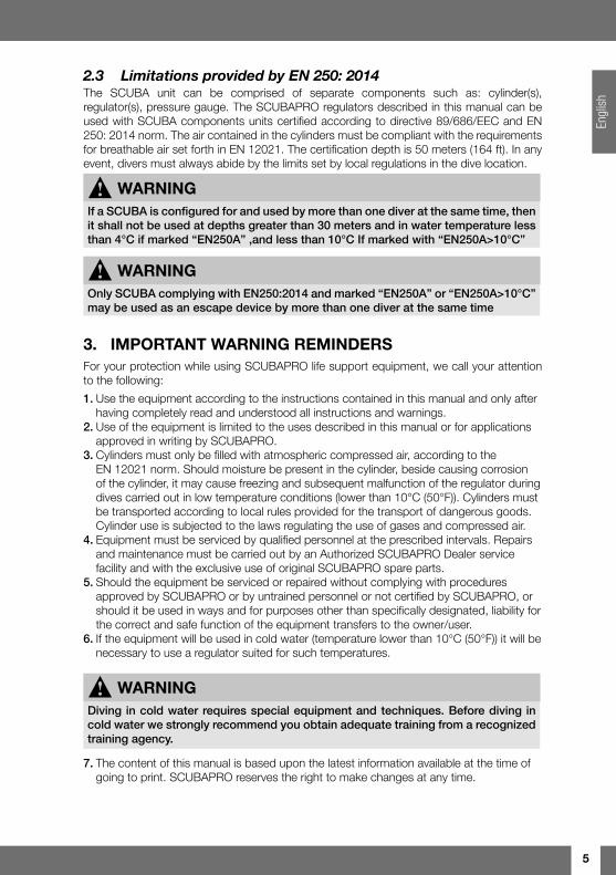
An example of a complete regulator and with either a DIN or INT connection first stage, depending on the tank valve:
11
10
72 98
1
63
45
2
15
34
Img. 1 Img. 2
1 First stage with threaded DIN connection 2 Second stage 3 INT/DIN inlet protective cap 4 DIN retaining wheel 5 Rotating swivel 6 High pressure port 7 Purge button 8 Exhaust deflector 9 Inhalation resistance control 10 V.I.V.A. control 11 Low pressure hose
1 First stage with yoke connection (INT) 2 Retaining yoke and screw 3 Protective cap 4 INT/DIN inlet protective cap 5 Dry balance chamber
All SCUBAPRO regulators can be identified via a serial number. The number is printed on the housing of the second stage and on the metal body of the first stage.
7
Engl
ish
SCUBAPRO offers a lifetime warranty to the original owner of all SCUBAPRO regulators. This warranty covers material and manufacturing defects (with the exception of o-rings, seats, filter, mouthpiece and low pressure hose).
In order to maintain this warranty, it is mandatory to perform service on the regulator by a Authorized SCUBAPRO Dealer service facility and maintain proof of service records. For details on the warranty please consult a SCUBAPRO Authorized Dealer.
4.3 Octopus(Emergencyauxiliarybreathingdevice)The octopus is usually considered as an auxiliary emergency second stage to be used by the diver in case of need (such as malfunction of its primary second stage).A SCUBA in octopus configuration is defined as an octopus second stage connected with the same first stage of the primary regulator.The EN250:2014 defines minimum safety requirement, testing and maximum depth (30 meters) in case the SCUBA is used by two divers at the same time with the octopus second stage used as an auxiliary emergency breathing escape device by another diver.
5. TECHNICAL FEATURESOur expertise in engineering and high quality components used in the manufacturing of SCUBAPRO regulators, combined with over 40 years of experience, ensure the maximum reliability and safety when you dive with a SCUBAPRO regulator. The main technical features of SCUBAPRO regulators are detailed below. To verify which of these features apply to any specific first and second stage combination, refer to the tables at the end of this chapter.
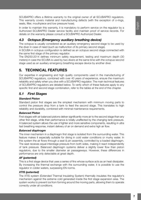
5.1 FirstStagesStandardPistonStandard piston first stages are the simplest mechanism with minimum moving parts to control the pressure drop from a tank to feed the second stage. This translates to high reliability and durability, combined with minimal maintenance requirements.
BalancedPistonFirst stages with air balanced pistons deliver significantly more air to the second stage than any other first stage, while their performance is totally unaffected by the changing tank pressure. A balanced system allows the use of lighter and more sensitive components, resulting in ultra fast breathing response, instant delivery of air on demand and extra high air flow.
BalanceddiaphragmThe inner mechanism in a diaphragm first stage is isolated from the surrounding water. This feature makes it especially suitable for diving in cold water conditions or murky water. In this system the air flows through a seat & pin assembly, controlled by a loaded diaphragm. The seat receives equal interstage pressure from both sides, making it react independently of tank pressure. Balanced diaphragm systems deliver a slightly lower flow than piston regulators, due to the smaller diameter air passageways. However, these differences in performance are only detectable at great depth.
AF(patented)This is a first stage device that uses a series of fins whose surface acts as an heat dissipater. By increasing the thermal exchange with the surrounding water, it is possible to use the regulator in colder waters, surpassing EN norms.
XTIS(patented)The XTIS system (Extended Thermal Insulating System) thermally insulates the regulator’s mechanism against the extreme cold generated inside the first stage expansion area. The system works to prevent ice from forming around the moving parts, allowing them to operate correctly under all conditions.
8
Drybalancechamber The dry chamber ensures the best performance in especially cold waters by preventing the entry of water inside the water balancing chamber. In extremely cold water conditions the formation of ice crystals around the main spring is thus eliminated.
Rotating swivelWith this feature, all inter-stage pressure hoses attached with the swivel have the ability to rotate in the best possible position to optimize hose distribution and lessen jaw fatigue.
High pressure portsAll first stages are equipped with at least one high pressure port. More sophisticated first stages are equipped with two high pressure ports, allowing a submersible pressure gauge, computer hose or transmitter to be positioned on the right or left side of the diver according to preference and/or correct transmitter orientation.
Intermediate pressure portsThe availability of 4 or 5 intermediate pressure ports enables the connection of equipment such as an octopus second stage, buoyancy compensator, dry suit hose or other accessories.
HFPortsThe HFPs (High Flow Ports) deliver a 15% higher capacity than standard low-pressure ports. The MK11 features two HFP ports, the MK21 and the MK17 EVO each have four, and the MK25 EVO has five.
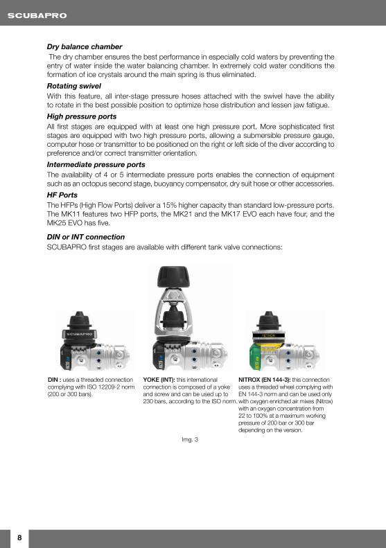
DINorINTconnectionSCUBAPRO first stages are available with different tank valve connections:
DIN : uses a threaded connection complying with ISO 12209-2 norm (200 or 300 bars).
YOKE (INT): this international connection is composed of a yoke and screw and can be used up to 230 bars, according to the ISO norm.
NITROX (EN 144-3): this connection uses a threaded wheel complying with EN 144-3 norm and can be used only with oxygen enriched air mixes (Nitrox) with an oxygen concentration from 22 to 100% at a maximum working pressure of 200 bar or 300 bar depending on the version.
Img. 3
9
Engl
ish
5.2 SecondStages
BalancedsystemBalancing the pressure forces acting within the demand valve allows the use of a much lighter spring load decreasing the inhalation resistance and providing a smoother breathing second stage.
DiveradjustableinhalationresistancecontrolSecond stages equipped with this system have an over-sized external control knob acting directly on the spring tension (Img. 1, point 9), allowing the diver to adjust the inhalation resistance in order to adapt it to the needs of the dive conditions. Adjusting the control knob (clockwise rotation) causes an increase in inhalation resistance. Adjusting with a counterclockwise rotation reduces the spring tension for lower inhalation effort. All depends on the diving conditions, such as in strong currents, when the diver spends some time with his head down and when the second stage is used as an alternate air source (octopus).
! WARNING A higher inhalation resistance does not necessarily imply a lower air consumption, in fact it may even have the opposite effect, due to the higher effort required to trigger the air flow increasing your work of breathing.
V.I.V.A.(patented)V.I.V.A. is the acronym for “Venturi Initiated Vacuum Assist.” High speed air flow passing over the vane creates a low pressure area inside the second stage housing. This depression pulls the diaphragm inside the housing, maintaining pressure on the valve lever and keeping the valve open without requiring an additional effort on the part of the diver. On some SCUBAPRO second stages the Venturi effect (V.I.V.A.) can be adjusted during the dive by changing the position of the flow vane via the knob positioned on the outside of the second stage. On SCUBAPRO second stages not equipped with an external knob, the V.I.V.A. vane position is preset to ensure maximum performance and prevent free-flow, but it can be adjusted at any time by a SCUBAPRO Authorized service technician.
10
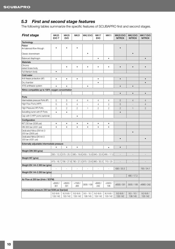
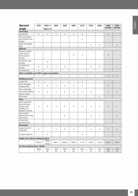
5.3 FirstandsecondstagefeaturesThe following tables summarize the specific features of SCUBAPRO first and second stages.
First stage MK25 EVO T
MK25 EVO
MK21 MK2 EVO MK17 EVO
MK11 MK25 EVO NITROX
MK2 EVO NITROX
MK17 EVO NITROX
TechnologyPistonAir-balanced-flow-through
Classic downstream
• • •
•
•
•
Balanced diaphragm • • •
MaterialsChrome plated brass body • • • • • • • •
Full titanium body •
Cold waterAnti-freeze protection (AF) • • • • • •
Dry chamber • •XTIS antifreeze system • • • • •
Nitrox compatible up to 100% oxygen concentration
• • •
PortsIntermediate pressure Ports (IP) 5 5 4 4 4 4 5 4 4
High Flow Ports (HFP) 5 5 4 - 4 2 5 - 4
High Pressure (HP) Ports 2 2 2 1 2 2 2 1 2
Swivelling turret with IP Ports • • •
Cap with 5 HFP ports (optional) •
Configuration
INT 230 bar (3336 psi) • • • • • •
DIN 300 bar (4351 psi) • • • • • •
Dedicated Nitrox EN144-3 200 bar (2900 psi)
•
Dedicated Nitrox EN144-3 300 bar (4351 psi) • •
Externally adjustable intermediate pressure
• • • • •
Weight DIN 300 (g/oz)
350 / 12.3 570 / 20.1 560 / 19.8 450 / 15.9 640 / 22.6 490 / 17.3 - - -
Weight INT (g/oz)
475 / 16.7 790 / 27.9 780 / 27.5 670 / 23.6 860 / 30.3 710 / 25 - - -
Weight EN 144-3 300 bar (g/oz)
- - - - - - 630 / 22.2 700 / 24.7
Weight EN 144-3 200 bar (g/oz)
490 / 17.3
Air Flow at 200 bar (l/min / SCFM)
>8500 / 301
>8500 / 301
>7500 / 265
3000 / 106>6900 /
242>5500 /
195>8500 / 301 3000 / 106 >6900 / 242
Intermediate pressure 230 bar/3336 psi (bar/psi)
9.2-9.8 / 133-142
9.2-9.8 / 133-142
9.2-9.8 / 133-142
9.5 - 10 / 138-145
9.2-9.8 / 133-142
9.2-9.8 / 133-142
9.2-9.8 / 133-142
9.5 - 10 / 138-145
9.2-9.8 / 133-142
11
Engl
ish
Secondstage
A700 S620 TI
*S620 X-TI
S600 G260 S560 C370 R195 R095 S560 NITROX
R195 NITROX
Technology
Air-balanced • • • • • • •
OFD downstream valve (Optimal Flow Design)
•
Classic downstream valve
• • •
Materials
Precision molded carbon fiber & technopolymer housing
• • •
Full titanium valve housing
•
Full metal valve housing
• • • • • • •
Full metal case •
Nitrox compatible up to 100% oxygen concentration
• •
Breathing comfort
Coaxial flow • •
Diver’s adjustable inhalation effort • • • • • • •
Diver’s adjustable VIVA (Venturi Initiated Vacuum Assist)
• • • • • • • • •
VIVA preset •
Hose
Sturdy super-flow hose with kevlar lining for extra durability and flawless air delivery
• • • • • • • • • •
Left and right attachment for extra convenience
• • • •
LP hose with spherical swivel
Mouthpiece
Supercomfort HF (High Flow)
• • • • • • • •
Compact high flow • •
Weight in air, without mouthpiece (g/oz)
261/9.2179/6.3*168/5.9
200/7.1 268/9.5 160/5.6 171/6 178/6.3 141/5.0 160/5.6 178/6.3
Air Flow at 200 bar (l/min / SCFM)
>2000/ 71
1850/ 66
1850/ 66
1800/ 64
1850/ 66
1600/ 57
1400/ 50
1400/ 50
1850/ 66
1400/ 50
12
6. PREPARING FOR USE
Before assembling the SCUBA unit verify that all components comply with local or European standards.
• Before connecting the first stage to the cylinder verify that the connection is free from dirt (sand, debris) and that the O-ring is undamaged.
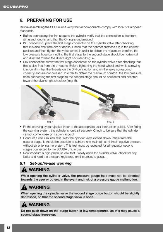
• INT connection: place the first stage connector on the cylinder valve after checking that it is also free from dirt or debris. Check that the contact surfaces are in the correct position and then tighten the yoke screw. In order to obtain the maximum comfort, the low pressure hose connecting the first stage to the second stage should be horizontal and directed toward the diver’s right shoulder (Img. 4).
• DIN connection: screw the first stage connector on the cylinder valve after checking that this is also free from dirt or debris. Before tightening the hand-wheel and while screwing it in, confirm that the threads on the DIN connection and on the valve correspond correctly and are not crossed. In order to obtain the maximum comfort, the low pressure hose connecting the first stage to the second stage should be horizontal and directed toward the diver’s right shoulder (Img. 5).
Img. 4 Img. 5
• Fit the carrying system/jacket (refer to the appropriate user instruction guide). After fitting the carrying system, the cylinder should sit securely. Check to be sure that the cylinder cannot come loose on its own accord.
• Conduct a vacuum leak test. With the cylinder valve closed slowly inhale from the second stage. It should be possible to achieve and maintain a minimal negative pressure without air entering the system. This test must be repeated for all regulator second stages connected to the SCUBA unit in use.
• Now conduct a high-pressure leak test. Slowly open the cylinder valve, check for any leaks and read the pressure registered on the pressure gauge.
6.1 Set-up/in-usewarning
! WARNING While opening the cylinder valve, the pressure gauge face must not be directed towards the user or others, in the event and risk of a pressure gauge malfunction.
! WARNING When opening the cylinder valve the second stage purge button should be slightly depressed, so that the second stage valve is open.
! WARNING Do not push down on the purge button in low temperatures, as this may cause a second stage freeze-up.
13
Engl
ish
• Close the cylinder valve and check the pressure gauge once again. During the first minute the displayed pressure should not decrease. Then open the valve again.
• If the cylinder valve is equipped with a reserve rod, verify that it is free to move downwards for its entire length. If you plan on using the reserve, ensure that the mechanical reserve valve is in the correct position (Up).
• Check that the entire SCUBA unit is functioning correctly by performing several complete breathing cycles (deep inhalation / exhalation) with the cylinder valve open and the second stage mouthpiece in the mouth.
• Check that all devices connected to the SCUBA unit are operating correctly. For example, check that the buoyancy compensator inflator (or the dry suit inlet valve) is functioning etc.
! WARNING Never connect a low pressure hose to a high pressure port. These connection threads are different sizes and are not compatible. Do not use adapters of any kind to connect low-pressure devices to high-pressure ports. Doing so could cause serious damage to both the user and equipment.
7. EQUIPMENT USECheck that the SCUBA unit is complete in all respects and complies with all requirements. Refer to the IMPORTANT WARNING REMINDERS and PREPARING FOR USE sections. Open the cylinder valve, don the equipment en put the second stage in your mouth, breathe deeply a few times to ensure that the system is operating correctly. When the mouthpiece is out of the mouth, simply pressing the purge button may trigger the Venturi effect and cause a regulator free-flow. The free-flow can be stopped by covering the mouthpiece opening with a finger.
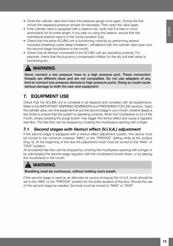
7.1 SecondstageswithVenturieffect(V.I.V.A.)adjustmentIf the second stage is equipped with a Venturi effect adjustment system, this device must be turned to the minimum (marked “MIN”) or the “PREDIVE” setting while at the surface (Img. 6). At the beginning of the dive the adjustment knob must be turned to the “MAX” or “DIVE” position. An accidental free-flow can be stopped by covering the mouthpiece opening with a finger or by submerging the second stage regulator with the mouthpiece turned down, or by placing the mouthpiece in the mouth.
! WARNING Breathing must be continuous, without holding one’s breath.
If the second stage is used as an alternate air source (octopus) the V.I.V.A. knob should be set to the “MIN” or the “PREDIVE” position for the entire duration of the dive. Should the use of this second stage be needed, the knob must be turned to “MAX” or “DIVE”.
14
Img. 6
! WARNING All dives must be planned and carried out so that at the end of the dive the diver will still have a reasonable reserve of air for emergency use. The suggested amount is usually 50 bars (725 psi).
7.2 Coldwateruse
! WARNING Diving in cold waters requires special equipment and techniques. Before attempting a cold water dive, obtain adequate training from a recognized certification agency.
EN 250: 2014 norm defines “cold waters” as those having a temperature lower than 10°C (50 °F) and requires that regulators certified for use in such conditions must be tested and approved to work properly in temperatures of 4°C (39 °F). If the SCUBA equipment is used in water with a temperature lower than 10 °C (50 °F) it is important to keep in mind the following:1. Use only regulators certified for use in these conditions. SCUBAPRO regulators certified
for use in cold water in accordance with norm EN 250: 2014 are marked with “EN250A”2. Remove the protective sleeves from both the ends of the LP hose3. Prior to the dive keep the regulator in a warm environment before fitting your regulator
on the tank.4. If the regulator is exposed to colder conditions, much lower than 0°C (32°F), set the
V.I.V.A. knob on “MIN” or “PREDIVE”) to avoid the risk of spontaneous and uncontrolled free-flow.
5. With high air flows the regulator first stage cools rapidly, therefore avoid high consumption rates during cold water dives. For example, avoid simultaneously using the buoyancy compensator and dry suit inflator and the alternate air source. It’s also advised to avoid checking the second stage function via the purge button, unless absolutely necessary. Ensure that the cylinder is filled only with air compliant with norm EN 12021.
! WARNING If a SCUBA is configured for and used by more than one diver at the same time, then it shall not be used at depths greater than 30 meters and in water temperature less than 4°C if marked “EN250A” and 10°C If marked with “EN250A>10°C”
! WARNING In extremely cold water diving, SCUBAPRO recommends the use of a cylinder equipped with two separate valves, connected to two complete regulators.
15
Engl
ish
7.3 PostdiveClose the cylinder valve and drain the system by pushing on the purge button of each second stage. Once the system has been depressurized disconnect the first stage regulator from the valve. All inlets must be closed with the provided protective caps to avoid the entry of debris, dirt or moisture (Img. 1 and Img. 2). If the cylinder valve is equipped with a reserve system the rod should be put in the “open” position (fully lowered) to indicate that the cylinder needs to be filled.
8. EQUIPMENT CARE AND MAINTENANCE
8.1 CareSCUBAPRO regulators are precision devices that are essential to the diver’s safety. For this reason SCUBAPRO uses only materials that have been selected, after thorough testing, as the best for efficiency and durability. To ensure that your SCUBAPRO regulator is always in perfect condition, a minimum of care and maintenance is required.After every dive and especially if in chlorinated water (pools), rinse the regulator with fresh water, preventing water from entering the system by following these steps:
1. Ensure that the high pressure inlet of the first stage regulator is closed with the special protective cap.
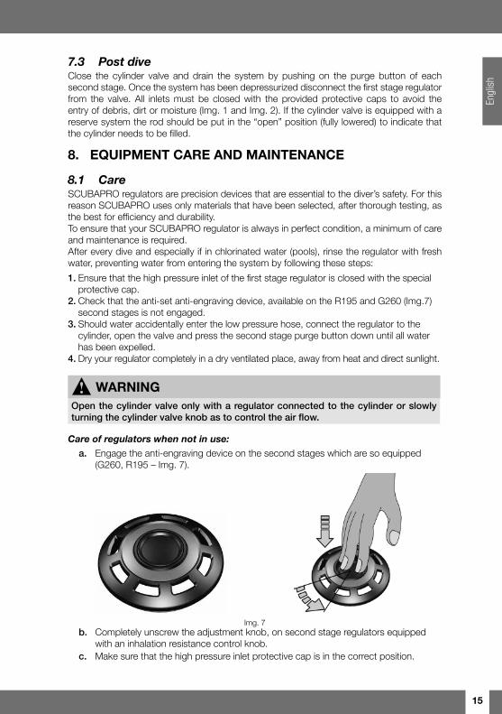
2. Check that the anti-set anti-engraving device, available on the R195 and G260 (Img.7) second stages is not engaged.
3. Should water accidentally enter the low pressure hose, connect the regulator to the cylinder, open the valve and press the second stage purge button down until all water has been expelled.
4. Dry your regulator completely in a dry ventilated place, away from heat and direct sunlight.
! WARNING Open the cylinder valve only with a regulator connected to the cylinder or slowly turning the cylinder valve knob as to control the air flow.
Careofregulatorswhennotinuse: a. Engage the anti-engraving device on the second stages which are so equipped
(G260, R195 – Img. 7).
Img. 7 b. Completely unscrew the adjustment knob, on second stage regulators equipped
with an inhalation resistance control knob. c. Make sure that the high pressure inlet protective cap is in the correct position.
16
d. Keep the regulator in a dry place, away from heat and direct sunlight. The mouthpiece should be periodically immersed in a disinfecting solution and rinsed with fresh water to completely remove the disinfectant. Do not use disinfectant substances that could damage the mouthpiece.
TEMPERATURE LIMITS: -10°C / 60°C
8.2 Maintenance
! WARNING Do not use silicone grease on silicone components, as this may cause some parts to deform. In addition, do not use silicone grease on components in the high pressure area of the first stage as this would compromise the compatibility with Nitrox mixes.
Maintenance procedures beyond the simple operations described in the preceding paragraph should not be carried out by the user but only conducted by a SCUBAPRO Authorized service technician. A SCUBAPRO regulator must be overhauled by an authorized Scubapro technician after 100 dives or not later than every 2 years, whichever comes first. The servicing is compulsory to preserve the limited lifetime warranty also. Please refer to the Johnson Outdoors warranty conditions.Servicing is available through SCUBAPRO Authorized dealers identified by the SELECTED DEALER SCUBAPRO sign or by visiting www.scubapro.com
9. NITROX
! WARNING To prevent severe and potentially lethal injuries DO NOT dive using Nitrox (oxygen enriched air) mixes unless you have first obtained adequate training and certification in their use by a recognized certification agency.
! WARNING Maximum operating depth (MOD) and exposure times to Nitrox (oxygen enriched air) mixes are dependent upon the oxygen concentration of the mix in use.
The term Nitrox (oxygen enriched air) defines breathable mixes composed of oxygen and nitrogen and containing oxygen in a percentage higher than 21% (atmospheric air). The higher oxygen concentration limits the use of these mixes with standard scuba equipment and requires the use of materials and procedures that differ from those required by the use of atmospheric air.
17
Engl
ish
USE OF NITROX MIXES OUTSIDE OF THE EUROPEAN UNION
Standard production SCUBAPRO regulators distributed to countries outside of the European Community use normal INT or DIN connections and are manufactured with materials, assembly procedures and lubricants that ensure compatibility with gas mixes containing oxygen up to 40%.In these countries, users are required to follow the same safety procedures that apply to dedicated nitrox regulators and to comply with the regulations set by each country concerning the use on Nitrox mixes for diving.
! WARNINGIf SCUBAPRO regulators have been used with standard compressed air it will be necessary to perform a new maintenance and cleaning procedure specifically designed for the use of nitrox mixes and carried out by a SCUBAPRO authorized technician, before using them again with Nitrox.
! WARNING Titanium is not compatible with Nitrox (oxygen-enriched air) mixes because it may ignite when exposed to high oxygen concentrations.Do not use a Titanium regulator with oxygen-enriched air at an oxygen percentage greater than 40%. There is no way to convert a Titanium regulator for use with oxygen-enriched air at an oxygen percentage greater than 40%.
USE OF NITROX MIXES WITHIN THE EUROPEAN UNION
Within the European Community the use of Nitrox mixes is regulated by norms EN 13949 and EN 144-3. SCUBAPRO has designed and manufactured a special regulator line that complies with the aforementioned regulations. The first and second stage regulators of this line are identified by the marking “Nitrox” and also feature components colored green or yellow, or marked with special stickers, to allow an immediate identification.These regulators can be used with oxygen enriched air containing an oxygen concentration higher than 22% and up to 100% (pure oxygen), at a maximum operating pressure of 200 bars (2900 psi) or 300 bar (4351 psi) depending on the version.
9.1 MainfeaturesofNitroxdedicatedregulatorsAs required by European Norms, Nitrox first stage regulator connections have been designed and approved to be used exclusively with Nitrox cylinders and cylinder valves, in order to prevent confusion with the corresponding standard-production compressed air regulators. SCUBAPRO Nitrox connections comply with EN 144-3.In Nitrox first stage regulators, compatibility with high pressure oxygen (higher than 40 bar / 580 psi and up to 200 bar / 2900 psi or 300 bar (4351 psi) depending on the version) is ensured by the choice of special materials used to manufacture seats, O-rings, gaskets and seals used in the high pressure first stage mechanism valves. Components are lubricated with a specific oxygen lubricant. SCUBAPRO Nitrox regulators are assembled in a dedicated area in order to comply with the high cleanliness standards required for oxygen compatibility.
9.2 UseandmaintenancenotesNitrox regulators must be used only with oxygen enriched air and only in combination with compressors and cylinders specifically dedicated to the use of Nitrox mixes. Breathable air (21% oxygen), even if compliant with European Norm EN 12021, can contain a certain
18
amount of hydrocarbons. These, while not constituting a health hazard, can ignite in the presence of a high concentration of oxygen.Should Nitrox regulators be used with compressed air coming from a compressor lubricated with standard oil they could be contaminated by flammable residues that would make them dangerous when used again with oxygen enriched air. In case of such a contamination, before using the regulator again with Nitrox, it will be necessary to disassemble it and perform an oxygen-specific cleaning in compliance with special procedures (for instance: CGA G-4.1 protocol or ASTM G93-88 or other officially approved procedures) carried out by a SCUBAPRO certified technician trained in oxygen cleaning and procedures.
1. During routine maintenance procedures it is required to use only genuine SCUBAPRO components specifically approved for the use with oxygen (seats, O-rings and lubricant).
2. After use, rinse thoroughly with fresh water, let dry completely before storing in a dry, clean, cool place.
3. Never use solvents as they might damage rubber and plastic components.4. Slowly open the cylinder valve in order to minimize the risk of ignition of the high oxygen
content mix.5. Components requiring lubrication (O-rings, etc.) must be treated only with suitable
products. In any case never use silicone grease on components used in the high pressure parts of the regulator, doing so would compromise the compatibility with Nitrox mixes.
A SCUBAPRO Nitrox EN 144-3 regulator must be overhauled by an authorized SCUBAPRO technician after 100 dives or not later than every year, whichever comes first. The servicing is compulsory to preserve safety and the limited lifetime warranty also. Please refer to the Johnson Outdoors warranty conditions.
! WARNING Do not use Nitrox regulators with oxygen enriched air if they have been used with compressed air. There might be residues of flammable materials that could cause serious accidents.
! WARNING Do not use silicone grease for the lubrication of Nitrox regulators.
! WARNING Second stage regulators, pressure gauges, consoles and other accessories used in combination with Nitrox first stage regulators must also be compatible with the use of Nitrox mixes.
19
Engl
ish
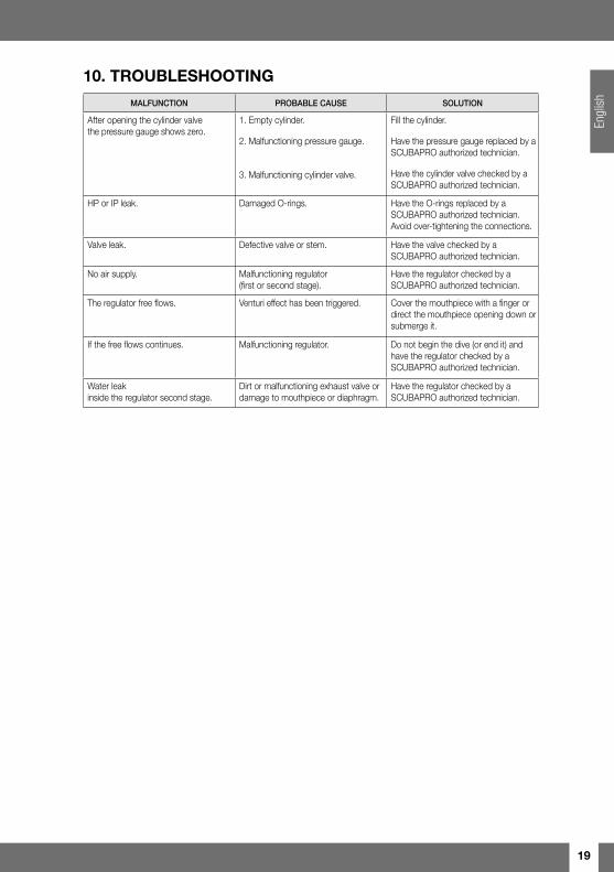
10. TROUBLESHOOTING
MALFUNCTION PROBABLE CAUSE SOLUTION
After opening the cylinder valve the pressure gauge shows zero.
1. Empty cylinder.
2. Malfunctioning pressure gauge.
3. Malfunctioning cylinder valve.
Fill the cylinder.
Have the pressure gauge replaced by a SCUBAPRO authorized technician.
Have the cylinder valve checked by a SCUBAPRO authorized technician.
HP or IP leak. Damaged O-rings. Have the O-rings replaced by a SCUBAPRO authorized technician. Avoid over-tightening the connections.
Valve leak. Defective valve or stem. Have the valve checked by a SCUBAPRO authorized technician.
No air supply. Malfunctioning regulator (first or second stage).
Have the regulator checked by a SCUBAPRO authorized technician.
The regulator free flows. Venturi effect has been triggered. Cover the mouthpiece with a finger or direct the mouthpiece opening down or submerge it.
If the free flows continues. Malfunctioning regulator. Do not begin the dive (or end it) and have the regulator checked by a SCUBAPRO authorized technician.
Water leak inside the regulator second stage.
Dirt or malfunctioning exhaust valve or damage to mouthpiece or diaphragm.
Have the regulator checked by a SCUBAPRO authorized technician.
20
Note
21
SUBSIDIARIES
SCUBAPRO AMERICASJohnson Outdoors Diving LLC1166-A Fesler StreetEl Cajon, CA 92020 - USA
SCUBAPRO ASIA PACIFIC1208 Block A, MP Industrial Center18 Ka Yip St.Chai Wan - Hong Kong
SCUBAPRO AUSTRALIAUnit 21 380 Eastern Valley WayChatswood NSW 2067-Australia
SCUBAPRO FRANCE(France, UK, Spain, Export: Netherlands, Belgium, Scandinavia)Nova Antipolis Les Terriers Nord175 Allée Belle Vue06600 Antibes - France
SCUBAPRO GERMANY & E. EuropeJohnson OutdoorsVertriebsgesellschaft mbHJohann-Höllfritsch-Str. 47 D-90530 Wendelstein - Germany
SCUBAPRO ITALYVia Tangoni, 1616030 Casarza Ligure (GE) - Italy
SCUBAPRO JAPAN3-9-1 SHIN-YAMASHITA, NAKA-KU, YOKOHAMA231-0801, JAPAN
SCUBAPRO SWITZERLANDBodenäckerstrasse 3CH-8957 SpreitenbachSwitzerland
For additional information about our distributors and dealers, see our web site at: www.scubapro.com
© 2008 by Johnson Outdoors Inc.
®
P/N
4510
1180
• re
v H
• 07
/201
7 •
Artb
ook
1345
3/17