Embed Size (px)
Citation preview

EN2910A: Advanced Computer ArchitectureTopic 04: Multi-threading, Multi-cores and GPUs
Prof. Sherief RedaSchool of Engineering
Brown University
1
Material from:• Parallel Computer Organization and Design by Debois, Annavaram and Stenstrom• Multi-threading architecture by Nemirovsky and Tullsen
Outline
1. Block (coarse-grain) HW multi-threading2. Interleaved (fine-grain) HW multi-threading3. Simultaneous multi-threading (SMT)4. Multi-cores5. General-purpose GPUs
2

Software multithreading• Used since the 1960’s to enable multiple users to use the same
computing system and to hide the latency of I/O operations and • Creating illusion of parallelism for multiple processes/threads using
context switching:1. Trap processor -- flush pipeline2. Save process state (includes register file(s), PC, page table base
register, etc) in OS process control block which is in memory.3. Restore process state of a different ready process4. Start execution -- fill pipeline
• On an I/O operation (or shared resource conflict or timer interrupt)1. Process is preempted and removed from ready list2. I/O operation is started3. Another active process is picked from the ready list and run4. When I/O completes preempted process back in the ready list
• Very high switching overhead (ok, since wait is very long)3

Multiprocessing enabled by SW multithreading
• Independent processes:– Separate independent applications (e.g, web browser
and text editor)– No programming effort– Cache interference– Most common (PC, workstations)– No speedup for individual threads– In effect thread slowdown– Thread need to exploit ILP or faster clock rates
4

Hardware multithreading• Vertical (cache misses and branch
mispredictions) and horizontal waste (ILP limits) can limit potential of superscalar processors.
• Exploit thread-level parallelism (TLP) using (1) core multi-threading and (2) multi-core processing
• HW runs multiple threads concurrently OS thinks there is more than one processor, each processing its own thread.
• HW threads share cache memory enables rapid communication by threads fine-grain communication by threads.
5
Vertical waste and horizontal waste of the issue bandwidth
of a four-wide superscalar processor.

Multiprocessing enabled by HW multithreading• Improvement through TLP (thread-level parallelism) not ILP
– Critical issue today– Software parallelization is an expensive effort– Legacy software – Some programs such as compilers are hard to parallelize
• Identify code fragments that can be executed in parallel– loops (loop-carried dependencies!!)– for LCD, values must be communicated between iterations as efficiently
as possible (mutual exclusion!!)– barrier synchronization at the end of loops– responsibility of the programmer
• Software libraries – provide macros or procedures for thread management– thread creation, synchronization, communication and termination– example: pthread, openMP
6

Core multithreading
• Run multiple threads on the same core concurrently• HW runs another thread when a thread is blocked on
1. l1 or l2 cache misses and TLB misses2. Exceptions and unsuccessful synchronization3. Waiting for operands (latency of operation)
• Three types of HW core multithreading:1. Block (coarse-grain) HW multi-threading2. Interleaved (fine-grain) HW multi-threading3. Simultaneous multi-threading (SMT)
7

1. Block multithreading (coarse grain)• Core has multiple contexts A hardware context is
the program counter, register file, and other data required to enable a software thread to execute on a core.
• Each running thread executes in turn until a long latency event switch out by flushing and load context of another thread.
• Similar to software multithreading but with HW support for fast context switch order less than 10 cycles versus thousands of cycles
• Block multithreading can hide long cache misses or blocked synchronization (e.g., waiting at a barrier). However, it typically cannot hide short inter-instruction latencies.
8

Required changes for block multi-threading
9
1. Fetch:• Multiple PCs; selector base on active thread• Miss in caches trigger context switching• I-cache stays the same, but I-TLB must include thread id
2. Read:• Need to replicate the register file might impact RF latency
3. Ex: Nothing4. MEM:
• D-cache has to be non-blocking; D-TLB must include thread id• Need to include a LD/ST buffer per thread for misses
5. WB:• Need to know the thread id.

Example of operation
10
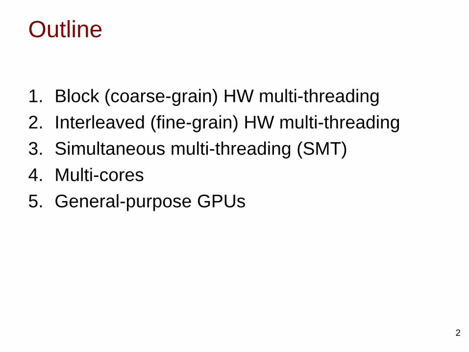
Block multi-threading in OOO superscalar• OOO cores
– the cost of switching threads is much higher– all instructions must leave the pipeline before the switch
11
X1
X3
X2 X4
X6
X5
Y2
Y3
Y4
Y1
Y5
Y6
2
2
4 4
21, 20
1
3
2
2
3
2
2
1
2
Thread 1 Thread 2
• thread 1 experiences a long latency event at instruction x5• thread switch is triggered when x5 reaches the top of ROB

Example
12
OoO processor with 2-WAY DISPATCH, 2-WAY ISSUE (ROB SIZE 4), 2 CDBs, 2-WAY RETIRE
More state duplication is useful: e.g., TLB, branch prediction

Block multithreading considerations
• Able to perform fast context switching and hide memory latencies full HW context per thread.
• Improves throughput and average execution time.
• Penalty is flushing the pipeline costly for OoOexecution.
• Potential interference in the caches• Required modifications to TLB and branch
predictor
13

2. Interleaved (fine-grain) multi-threading
• Dispatch instructions from different threads/processes in each cycle – Able to switch between
contexts (threads) as every cycle with no switch delay.
– Takes advantage of small latencies such as instruction execution latencies
– Does not address horizontal waster but can eliminate vertical waste
14

Interleaved architecture example
15
• Two threads: penalty of a taken branch is one clock and penalty of an exception is three clocks.
• Five threads: penalty of a taken branch is zero and penalty of an exception is one clock.

Interleaved multi-threading architecture
16
Same architecture as for block multithreading except that:• Data forwarding must be thread aware• Context id is carried by forwarded values• Stage flushing must be thread aware• On an miss exception IF, ID, EX and MEM cannot be flushed
indiscriminately• Same for taken branches and regular software exceptions• Thread selection algorithm is different: a different thread is selected
in each cycle (round-robin)• On a long latency event the selector puts the thread aside and
removes it from selection

Impact of increasing number of contexts
• Fetch can be simplified no need for branch prediction and control hazard circuit
• Forwarding can be eliminated and no need for data hazard hardware
• Issues:– Single-thread performance can suffer– Register file needs to increase proportionally.– Interference in cache.– Augmenting TLBs with thread ids.
17

Example: Sun/Oracle UltraSparc T1
18
• Targets server market for transactional applications high TLP• T1 (introduced in 2005) 8 cores @ 1.4 GHz – 72W• Each core supports four thread contexts total 32 HW threads
OS sees 32 virtual/logical cores• Each core is in-order scalar core with simple 6-stage pipeline: fetch,
thread select, decode, execute, memory, writeback.• L2 cache shared among all cores using a cross bar• Static branch prediction using a hint bit

Pros and Cons• Pros: Very energy/area efficient design that keeps pipeline full busy
without power hungry logic (e.g., out-of-order scheduler, register renaming, dependence checking, bypassing, etc).
• Cons:– To keep pipeline full with one instruction per thread more
contexts (large RF) and complex thread selection logic.– Single-thread performance suffers greatly
• Not popular for OoO superscalar multiple instructions from the thread per cycle need dependency checking and branch prediction
• Most fine-grain multi-threading architectures have been based on VLIW architectures.
19

3. Simultaneous multi-threading (SMT)
20
• Extension of interleaved multi-threading to OoO cores.
• Instructions from multiple threads are available to dispatch, decode and issue in every cycle reduces both horizontal and vertical waste.
• Concept of context switching is not applicable.• Used in Intel Pentium 4, IBM Power5, Intel
Core i7, Core i5 and Xeon processors in conjunction with multicores. AKA hyperthreading in Intel products.
• Could either share the full issue dispatch width among the threads or partition.

SMT Hardware requirements• In addition to replicating architectural
state, need to either replicate or share and tag the following HW units: instruction fetch queue, ROB, RAT, and LD/ST queues.
• Instruction scheduling, data forwarding and flushing must be thread-aware every instruction must carry its thread
• RS are shared but must include tags thread id.
• Cache stays the same; TLB must be thread aware
• Branch prediction should be thread aware, especially if global branch predictors are used.
21

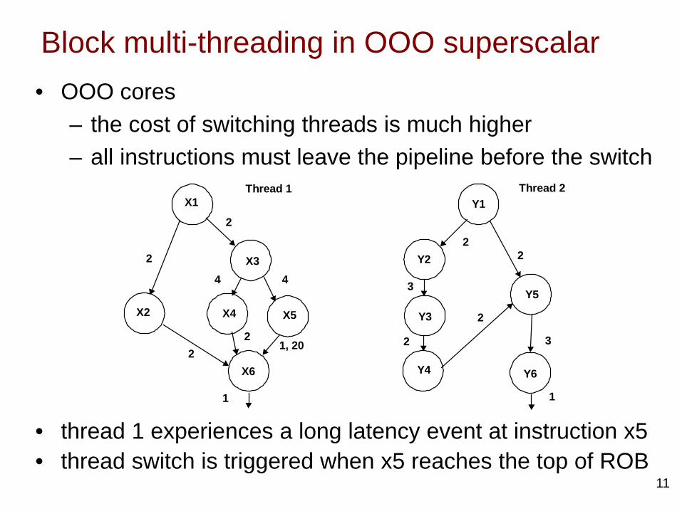
SMT Execution in OoO core
22
X1
X3
X2 X4
X6
X5
Y2
Y3
Y4
Y1
Y5
Y6
2
2
4 4
21, 20
1
3
2
2
3
2
2
1
2
Thread 1 Thread 2
• Similar as previous example: two-way OoO superscalar with SMT such that one instruction from each instruction is dispatched in each cycle dispatch bandwidth is partitioned.
• Compare throughout with coarse grain HW multithreading!• Fix Y2(2) to Y2(3).

Example: Intel Nehalem Core i7
23
• Introduced 2008.• Quad-core processor.• Each core contains two
hardware contexts and a 4-wide superscalar out-of-order pipeline total 8 logical cores.
• Share SMT dispatch bandwidth among the two thread contexts
• 64 KB L1 cache/core (32K I and 32K D-cache), 256 KB L2 cache per core, and shared 4-12 MB L3 cache.

4. Multi-core processors (chip multi-processors )
• CMPs have several desirable properties– design simplicity– improved power scalability– low-latency communication– modularity and customization
• CMPs can be homogeneous or heterogeneous• How can cores communicate through shared cache?
24
IBM Power 8AMD A10Intel Core i7

A. Bus-based CMPs
25
L1 $
Core0
L1 $
Core1
L1 $
Core2
L1 $
Core3
L2 $ Bank0
L2 $ Bank1
L2 $ Bank2
L2 $ Bank3
RouterSnoop
Coherence on Bus
Memory Controller
BUS INTERCONNECT
• Cores share L2 cache banks through a shared bus. Address N is located in bank N mod 4.
• Coherence is maintained between L1s by bus snooping• Only one node can access bus at a time• BW is fixed• Bus architectures does not scale well.• Example: Intel Core 2 Duo

B. Ring-based CMPs
26
L1 $
Core0
L1 $
Core1
L1 $
Core2
L1 $
Core3L2 $ Bank0
L2 $ Bank1
L2 $ Bank2
L2 $ Bank3
Router Directory Coherence
QPI/HT Interconnect
Memory Controller
• Nodes [core + L2 bank (or LLC)] are connected through a ring• Multiple requests are in progress on different links as long as
they do not use same link in same cycle• Rings can be clocked faster than busses• Packets are routed by additional logic in each node (routers)• Examples: Nehalem Core i7 with shared L3 cache
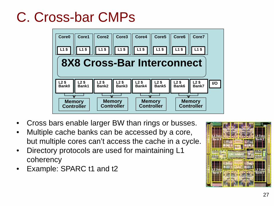
C. Cross-bar CMPs
27
L1 $
Core0
L1 $
Core1
L1 $
Core2
L1 $
Core3
L1 $
Core4
L1 $
Core5
L1 $
Core6
L1 $
Core7
L2 $ Bank0
L2 $ Bank1
L2 $ Bank2
L2 $ Bank3
L2 $ Bank4
L2 $ Bank5
L2 $ Bank6
L2 $ Bank7
8X8 Cross-Bar Interconnect
Memory Controller
Memory Controller
Memory Controller
Memory Controller
I/O
• Cross bars enable larger BW than rings or busses.• Multiple cache banks can be accessed by a core,
but multiple cores can’t access the cache in a cycle.• Directory protocols are used for maintaining L1
coherency• Example: SPARC t1 and t2

Multi-core cache bandwidth• Off-chip bandwidth is a critical resource in multi cores
– pin count, frequency• Memory wall problem replaced by bandwidth problem• Mitigate using large shared caches
– No coherence problem– Cooperative sharing (code and data sharing); effective size is
greater because of sharing– Destructive interference:
• threads do not help each others• each thread sharing the cache competes with other threads• as the thread count increases, the amount of cache per
thread decreases• misses and contention both increase
28

5. GP-GPU systems
29
CPU+
GPU
Unified NB
DRAM
PCIe based systems Fusion systems
• PCIe 4 or 8 Gb/s Communication bandwidth is an overhead offload to GPU if benefits overweigh costs.
• GPU and CPU on same die share memory hierarchy reduce communication overhead
• GPU is not as capable as PCIe based GPUs
Some figures from “Performance Analysis and Tuning for General Purpose Graphics Processing Units (GPGPU)” by Kim et al.

Overall architecture
30
• Goal: Maximize aggregate flop throughput • Cores called streaming multiprocessors (SM in nVidia) or compute
units (CU in AMD). • Three distinguishing features of GPUs:
1. SMs use wide floating-point SIMD units. 2. SMs support HW multithreading for multiple contexts.3. Smaller L2/L3 caches.
SMnVidia Fermi
3 billion transistors16 SM
768 KB L2 cache1.4 GHz
1.3 TFLOPS - 244 W
L2 cache

SM architecture
31
[source: S. Soller]
• In-order cores (FE/DE/EX/MEM/WB) with support for multiple threads large execution contexts (32 KB) special RF designs to maximize RF bandwidth.
• HW context switching is round robin between ready multiple threads no need for BP and forwarding.
• Cache misses removal from ready context switching hide memory latencies
• Instructions for each core are SIMD or Single Instruction multiple threads (SIMT). Also known as warp in nvidia’s literature

Thread scheduling
• Each SM switches contexts among the wraps of the threads blocks assigned to it.
• All threads belonging to a warp/SIMT are scheduled together.
• When an instruction stream (warp) is stuck waiting for its data switch to a different warp hide memory latency
• To make switching efficient: Have more than one context rather than swapping contexts
32

Example: Hiding memory stalls
33[slide from Kayvon Fatahalian]

Example: Hiding memory stalls
34[slide from Kayvon Fatahalian]

Example: Hiding memory stalls
35[slide from Kayvon Fatahalian]

Example: Hiding memory stalls
36[slide from Kayvon Fatahalian]

SM organization
37
• Scheduling: multiple PCs, one per wrap. Scheduler either (1) picks one from the ready list in a round-robin fashion; or (2) picks one from the ready list in a greedy fashion.
• How to handle branch instructions within a wrap?
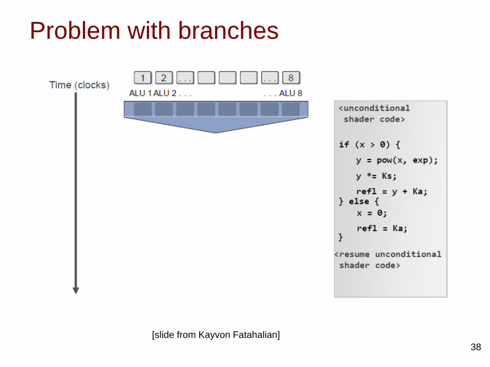
Problem with branches
38[slide from Kayvon Fatahalian]
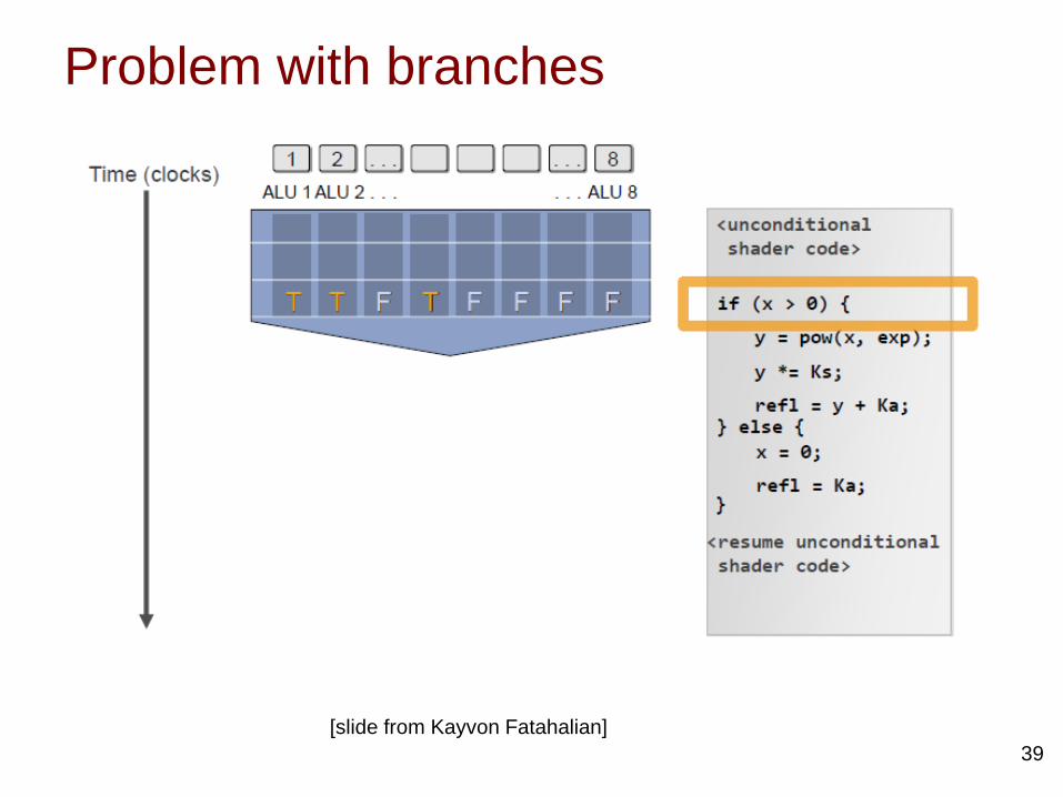
Problem with branches
39[slide from Kayvon Fatahalian]

Problem with branches
40[slide from Kayvon Fatahalian]

Handling branch instructions• A SMs fetch just one instruction for each
warp. When this instruction is a divergent branch, threads within a warp will need to execute different instruction paths.
• Solutions:1. Use predicated instructions and per-
thread-lane masks.2. Branch synchronization stack
1. When threads diverge, hardware stack records convergence point and PC of starting addresses of other branches.
2. SM executes fetches from one path, and when it is done, it restored the PC of the wrap from the stack.
41

Memory hierarchy
42
CPU cache provide low latency and high BW
GPU No cache hierarchy – needs high BW to main memory – memory latency
hidden by large number of threads
[source O. Rosenberg]

GPU DRAM
• 43
• For PCIe based, GPU has its own DRAM• Special DRAM interface (GDDR) for higher BW but longer
latencies compared to regular DRAM interfaces (DDR)• DRAM directly soldered on board can’t upgrade like
traditional DRAM but get better results

Example: nVidia GeForce GTX 480 (Fermi)
44
Each Streaming Multiprocessor (SM) :• 32 cores, each handles MAC (2 FLOPS) per cycle• handles two warps at the each clock cycle• Each warp can have 16 threads• Up to 48 warps can be interleaved
3 billion transistors15-16 SM each with 32 SIMD units
768 KB L2 cache1.4 GHz
15*32*2*1.4=1.3 TFlops- 244 W

When CPU or GPU?
• CPU:– High data dependency application does not
scale into large number of threads – Mixture of operations – Heavy branching and control
• GP-GPU:– High data parallelism– Application can be decomposed into
independent threads running same instruction– Limited control flow
45