Embed Size (px)
Citation preview

Aerospace Science and Technology 24 (2013) 95–100
Contents lists available at SciVerse ScienceDirect
Aerospace Science and Technology
www.elsevier.com/locate/aescte
Short communication
Enabling leg-based guidance on top of waypoint-based autopilots for UAS
Xavier Prats ∗, Eduard Santamaria, Luis Delgado, Noel Trillo, Enric Pastor
Technical University of Catalonia (UPC), Castelldefels School of Telecommunications and Aerospace Engineering, Esteve Terradas, 7, 08860 Castelldefels, Spain
a r t i c l e i n f o a b s t r a c t
Article history:Received 20 May 2011Received in revised form 6 September 2011Accepted 20 September 2011Available online 24 September 2011
Keywords:Leg-based guidanceRNAV navigationAutopilotUAS
This paper presents a methodology to extend the guidance functionalities of Commercial Off-The-Shelfautopilots currently available for Unmanned Aircraft Systems (UAS). Providing that most autopilots onlysupport elemental waypoint-based guidance, this technique allows the aircraft to follow leg-based flightplans without needing to modify the internal control algorithms of the autopilot. It is discussed howto provide Direct to Fix, Track to Fix and Hold to Fix path terminators (along with Fly-Over and Fly-By waypoints) to basic autopilots able to natively execute only a limited set of legs. Preliminary resultsshow the feasibility of the proposal with flight simulations that used a flexible and reconfigurable UASarchitecture specifically designed to avoid dependencies with a single or particular autopilot solution.
© 2011 Elsevier Masson SAS. All rights reserved.
1. Introduction
Unmanned Aircraft Systems (UAS) are, at present, mainly de-signed for military missions and very few civil applications havebeen developed so far because of the lack of an appropriate regu-lation framework concerning their certification, airworthiness andoperations. An important consequence is that the development ofUAS has always been highly dependent on the mission and theflight scenario. Thus, very specific and non-flexible systems existnowadays to control the desired flight plan, the UAS mission, thesensor activation/configuration, the data storage, etc. This fact maydelay and increase the implementation costs (and risk) of a newUAS application. The core of a UAS is probably the autopilot and,in order to develop all necessary mission avionics on top of it, it isessential to understand how this device works, what kind of inputssupports and what are its capabilities.
There are a considerable amount of Commercial Off-The-Shelf(COTS) autopilots designed for UAS (refer for instance to the sur-vey done in [2]). A well-known drawback regarding this technologyis that the flight plan definition is composed by just a collectionof statically defined waypoints (or hand-manipulated by the UASoperator), which are flown in sequence. Using a basic list of way-points as the mechanism for flight planning specification has sev-eral important limitations, such as the difficulty to specify complextrajectories (needed for most of the UAS typical missions), the lackof support for specifying repetitive or conditional behaviour in the
* Corresponding author.E-mail addresses: [email protected] (X. Prats), [email protected]
(E. Santamaria), [email protected] (L. Delgado), [email protected](N. Trillo), [email protected] (E. Pastor).
URL: http://icarus.upc.edu (X. Prats).
flight plan, etc. To address these limitations, in [8,6] a new flightplan specification language has been proposed that uses higherlevel constructs, with richer semantics, and which enables the UASflight to be adapted to the circumstances encountered during themission.
Besides basic trajectories, the flight plan specification supportsconstructs for conditional and iterative behaviour together withmission-oriented area scanning and other built-in patterns. Theflight plan submitted to the UAS contains a nominal path that canbe modified in real-time by updating a number of specific param-eters. Moreover, the flight plan can be accompanied by alternativesto respond to emergency situations as well as specific proceduresfor approach and departure operations. The details of this flightplan specification language are found in [8], which also describesthe overall architecture of the system with a special emphasis onthe software components involved in the execution of the flightplan. These software components run on embedded hardware in-stalled on-board the UAS. Additionally, the human machine in-terfaces required to fully exploit the new dynamic characteristicsoffered by the flight plan language are detailed in [6]. The afore-mentioned references, however, do not go into detail regarding thetranslation mechanism used to generate waypoints for the differ-ent flight plan primitives. This article provides insights on howthis translation process takes place and shows how the proposedmethodology can be used to implement primitives found in theflight plan specification language on top of autopilots with differ-ent navigation capabilities.
Current COTS autopilots for UAS do not support any of these ca-pabilities and the required guidance functionalities. Based on Area
1270-9638/$ – see front matter © 2011 Elsevier Masson SAS. All rights reserved.doi:10.1016/j.ast.2011.09.006
96 X. Prats et al. / Aerospace Science and Technology 24 (2013) 95–100
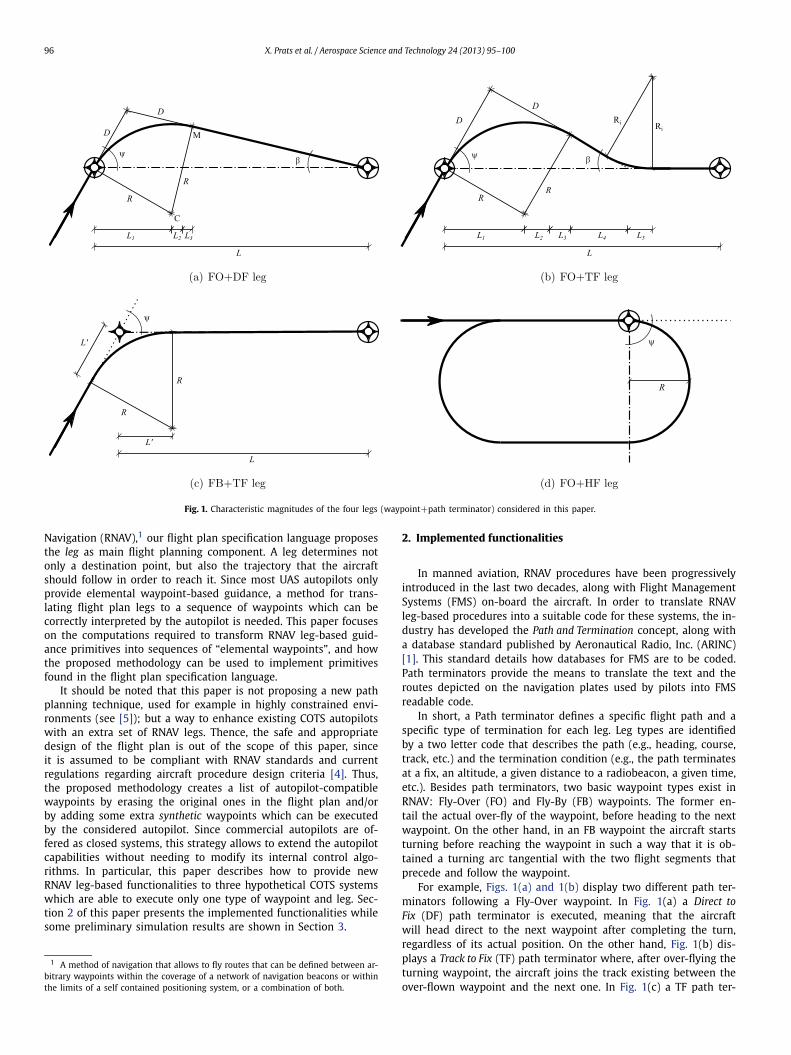
Fig. 1. Characteristic magnitudes of the four legs (waypoint+path terminator) considered in this paper.
Navigation (RNAV),1 our flight plan specification language proposesthe leg as main flight planning component. A leg determines notonly a destination point, but also the trajectory that the aircraftshould follow in order to reach it. Since most UAS autopilots onlyprovide elemental waypoint-based guidance, a method for trans-lating flight plan legs to a sequence of waypoints which can becorrectly interpreted by the autopilot is needed. This paper focuseson the computations required to transform RNAV leg-based guid-ance primitives into sequences of “elemental waypoints”, and howthe proposed methodology can be used to implement primitivesfound in the flight plan specification language.
It should be noted that this paper is not proposing a new pathplanning technique, used for example in highly constrained envi-ronments (see [5]); but a way to enhance existing COTS autopilotswith an extra set of RNAV legs. Thence, the safe and appropriatedesign of the flight plan is out of the scope of this paper, sinceit is assumed to be compliant with RNAV standards and currentregulations regarding aircraft procedure design criteria [4]. Thus,the proposed methodology creates a list of autopilot-compatiblewaypoints by erasing the original ones in the flight plan and/orby adding some extra synthetic waypoints which can be executedby the considered autopilot. Since commercial autopilots are of-fered as closed systems, this strategy allows to extend the autopilotcapabilities without needing to modify its internal control algo-rithms. In particular, this paper describes how to provide newRNAV leg-based functionalities to three hypothetical COTS systemswhich are able to execute only one type of waypoint and leg. Sec-tion 2 of this paper presents the implemented functionalities whilesome preliminary simulation results are shown in Section 3.
1 A method of navigation that allows to fly routes that can be defined between ar-bitrary waypoints within the coverage of a network of navigation beacons or withinthe limits of a self contained positioning system, or a combination of both.
2. Implemented functionalities
In manned aviation, RNAV procedures have been progressivelyintroduced in the last two decades, along with Flight ManagementSystems (FMS) on-board the aircraft. In order to translate RNAVleg-based procedures into a suitable code for these systems, the in-dustry has developed the Path and Termination concept, along witha database standard published by Aeronautical Radio, Inc. (ARINC)[1]. This standard details how databases for FMS are to be coded.Path terminators provide the means to translate the text and theroutes depicted on the navigation plates used by pilots into FMSreadable code.
In short, a Path terminator defines a specific flight path and aspecific type of termination for each leg. Leg types are identifiedby a two letter code that describes the path (e.g., heading, course,track, etc.) and the termination condition (e.g., the path terminatesat a fix, an altitude, a given distance to a radiobeacon, a given time,etc.). Besides path terminators, two basic waypoint types exist inRNAV: Fly-Over (FO) and Fly-By (FB) waypoints. The former en-tail the actual over-fly of the waypoint, before heading to the nextwaypoint. On the other hand, in an FB waypoint the aircraft startsturning before reaching the waypoint in such a way that it is ob-tained a turning arc tangential with the two flight segments thatprecede and follow the waypoint.
For example, Figs. 1(a) and 1(b) display two different path ter-minators following a Fly-Over waypoint. In Fig. 1(a) a Direct toFix (DF) path terminator is executed, meaning that the aircraftwill head direct to the next waypoint after completing the turn,regardless of its actual position. On the other hand, Fig. 1(b) dis-plays a Track to Fix (TF) path terminator where, after over-flying theturning waypoint, the aircraft joins the track existing between theover-flown waypoint and the next one. In Fig. 1(c) a TF path ter-

X. Prats et al. / Aerospace Science and Technology 24 (2013) 95–100 97
Table 1Required modifications on the nominal flight plan in order to enhance a system capable of executing only one type of leg (waypoint+path terminator).
System capability Implemented leg Delete original WP? Extra virtual WPs Coordinates of the extra waypoints (WPs)
FO+DF FO+TF No WP1 x1 = L1 + L2 + L3 + L4 − L5 cosβ y1 = L5 sin β
FB+TF Yes WP1 x1 = −L′ · cosψ y1 = −L′ · sinψ
FO+HF No WP1 x1 = −L′′ y1 = −2R
FO+TF FO+DF No WP1 x1 = L1 + L2 + L3 y1 = (L − L1 − L2 − L3) tanβFB+TF Yes WP1 x1 = −L′ · cosψ y1 = −L′ · sinψ
WP2 x2 = L′ y2 = 0
FO+HF No WP1 x1 = 0 y1 = −2RWP2 x2 = −L′′ y2 = −2RWP3 x3 = −L′′ y3 = 0
FB+TF FO+DF Yes WP1 x1 = D cosψ y1 = D sin ψFO+TF Yes WP1 x1 = D cos ψ y1 = D sin ψ
WP2 x2 = L1 + L2 + L3 + L4 y2 = 0
FO+HF YesWP1 x1 = R y1 = 0WP2 x2 = R y2 = −2RWP3 x3 = −(L′′ + R) y3 = −2RWP4 x4 = −(L′′ + R) y4 = 0
minator is shown after a Fly-By type waypoint, while in Fig. 1(d) aHold to Fix (HF) follows the Fly-Over waypoint.
There exist up to 23 different path terminators, even if most ofthe FMS can usually execute a small set of them [3]. This paperdescribes how to provide new RNAV functionalities to three hypo-thetical systems which are able to execute only one type of leg(waypoint+path terminator). These three studied systems are:
• FO+DF: System capable of Fly-Over (FO) waypoints followedby Direct to Fix (DF) path terminators.
• FO+TF: System capable of Fly-Over (FO) waypoints followedby Track to Fix (TF) path terminators.
• FB+TF: System capable of Fly-By (FB) waypoints followed byTrack to Fix (TF) path terminators.
Among all RNAV path terminators, DF, TF and HF are the mostbasic and common ones, allowing an autopilot to execute a widerange of basic RNAV procedures already published in many coun-tries [3]. In this paper, the following legs will be implemented foreach of the three previous considered systems: FO+DF, FO+TF,FB+TF and FO+HF.2 In Fig. 1, the nominal trajectory and asso-ciated magnitudes of these four transitions, when considering acourse change of angle ψ , are shown.
Assuming an aircraft performing a coordinated turn at a con-stant bank angle φ and with no altitude change, the nominal turnradius is given by:
R = v2
g tanφ(1)
where v is the aircraft airspeed, while g � 9.81 m s−1 is the ac-celeration of the gravity. The bank angle is an aircraft dependentparameter, taking in general, values around φ = 25◦ in manned air-craft [7]. For UAS, however, higher values can be foreseen.
For an FO+DF transition (Fig. 1(a)), the aircraft turns in sucha way that its new heading leads directly to the next waypoint.Therefore, the interception angle for this waypoint is a function ofthe course change (ψ ), the length of the leg (L) and the turn radius(R). The analytical computation of this angle β(ψ, L, R) is given inAppendix A of this paper. Conversely, for an FO+TF transition (seeFig. 1(b)), this interception angle is fixed beforehand to a typicalvalue of β = 30◦ [4].
2 Note that the combination FB+DF is senseless and that the HF path terminatormust always follow an FO waypoint [1].
From Fig. 1 and after some basic trigonometric analysis, somecharacteristic length magnitudes describing each transition can becomputed as follows:
L1 = R sinψ L2 = R cosψ tanβ
L3 = R sinβ
(1 − cosψ
cosβ
)L4 = R
cos2 β
sinβ
(1 − cosψ
cosβ
)
L5 = Ri tanβ
2L′ = R tan
ψ
2
D = R tan
(ψ + β
2
)(2)
The methodology proposed in this paper to enhance the basicautopilot capabilities is by adding extra virtual waypoints and/or byeliminating the original waypoint to/from the original flight plan.This modification of the nominal list of waypoint is computed ina way that the trajectory obtained when executing the new flightplan with a basic autopilot, matches with the trajectory we wouldobtain had the original flight plan been executed with an autopilotcapable to perform natively the required waypoint and path termi-nator types.
According to this methodology, Table 1 summarises all themodifications required on the nominal flight plan in order to vir-tually provide the autopilot with the four new leg capabilities(FO+TF, FO+DF, FB+TF and FO+HF). Thus, for each new imple-mented leg, the table shows the cases when the original waypointshould be deleted from the flight plan and how many extra vir-tual waypoints are needed to code. For each extra waypoint, itslocation is given in a Cartesian coordinate system (x, y), centred atthe nominal waypoint of study and with the x axis aligned withthe line joining this waypoint with the following waypoint in theflight plan sequence. In Figs. 2, 3 and 4, the location of these newwaypoints is shown graphically for each of the new implementedleg. These figures correspond to autopilots capable to execute onlyFO+DF, FO+TF and FB+TF transitions, respectively.
3. Preliminary implementation and simulation infrastructure
The implementation of the described methods forms part of anon-going effort by the authors to build a UAS architecture able toexecute leg-based procedures that is not locked-in to a single au-topilot solution. Fig. 5 displays the simulation environment thathas been set up to test the presented approach. The Flight PlanManager (FPMa) and the Virtual Autopilot System (VAS) are soft-ware components, on-board the UAS platform, that communicate

98 X. Prats et al. / Aerospace Science and Technology 24 (2013) 95–100
Fig. 2. Enhancing an autopilot capable to execute only FO+DF legs.
Fig. 3. Enhancing an autopilot capable to execute only FO+TF legs.
Fig. 4. Enhancing an autopilot capable to execute only FB+TF legs.
with each other through a Local Area Network. A document de-scribing the flight plan using our leg-based specification languageis submitted to the FPMa to perform its execution. This component,by using the above presented equations, computes the sequenceof waypoints that the flight plan translates into, and sends themto the VAS; which in turn, provides a hardware-independent in-terface to interact with the autopilot. As shown in the figure, theimplementation of the VAS is divided into two blocks: one fac-ing the network and another one facing the UAS platform. Whilethe former is always the same, the latter depends on the actualautopilot system and implements the communication protocols re-quired by the autopilot. Therefore, as illustrated, one could have animplementation that is able to operate with a given commercialautopilot and another one for interacting with a particular flight
simulator. The installed autopilot system is ultimately responsiblefor implementing the guidance and control loops.
The presented simulations have been performed by using theFlightGear open source flight simulator.3 Fig. 6(a) displays the re-sults of an example simulation when the VAS interacts with anautopilot capable of executing only FO waypoints followed by DFpath terminators. The figure displays the flight plan legs as straightlines connecting different waypoints, which can be either FB or FO.The actual list of waypoints generated by the FPMa is drawn ontop, together with the actual flight trajectory obtained after thesimulation. Leg A is a TF leg that connects an FO waypoint (2)
3 See http://www.flightgear.org.

X. Prats et al. / Aerospace Science and Technology 24 (2013) 95–100 99
Fig. 5. Simulation environment.
Fig. 6. Simulation results using systems with different basic leg capabilities.
to an FB destination waypoint (5). Since the simulated autopilotdeals natively with FO waypoints, no special treatment is requiredfor waypoint (2). An extra waypoint (3) is needed to intercept thetrack and the original destination waypoint (5) is moved to a newposition (4) to actually perform a fly-by manoeuvre. Leg B is also aTF leg and as in leg A, the destination waypoint (7) is moved to anew position (6) in order to perform a fly-by. With the destinationwaypoint (8) of leg C being an FO followed by a DF leg, no spe-cial waypoint transformations are required for the rest of the flightplan.
A different flight plan and its execution are shown in Fig. 6(b)to demonstrate how the system deals with an autopilot that sup-ports only FB waypoints followed by TF path terminators. Leg A ofthis flight plan is also a TF leg that starts with an FO waypoint (2).Since FO waypoints are not natively supported, waypoint 2 needsto be removed and two extra FB waypoints are added (3 and 4).Legs B and C are DF legs that start with an FO waypoint (respec-tively, waypoints 5 and 7) and in both cases, the aircraft followsthe track between a displaced initial waypoint (6 and 8) and theleg’s destination.
4. Conclusion
Area Navigation, coupled with other technologies, is enablinga move towards trajectory-based operations. Bringing trajectory-based capabilities to UAS will make them easier to integrate intonon-segregated airspace and also increase their ability to performmissions which require complex trajectories to be flown (such asloitering over certain areas). Most of current commercially avail-
able autopilot solutions, however, only provide waypoint-basedguidance. Moreover, due to the closed nature of these systems, itis not possible to modify them in order to implement leg-basedguidance. A possible solution to enhance such basic autopilots is toconveniently modify the original flight plan, as it has been shownin this paper.
Since the presented simulations have been carried out withoutconsidering wind conditions, arguably, the results only confirm thecorrectness of the analytical equations proposed and their imple-mentation. Nevertheless, the simulation infrastructure provides avaluable test-bed for further developments and work is underwayto include wind estimations into the presented waypoint genera-tion equations. Moreover, a sensitivity analysis of the uncertaintiesin parameters such as aircraft airspeed and bank angles, is alsoforeseen. Besides that, we also plan to close the loop between theFlight Plan Manager and the Virtual Autopilot so that the formerwill be able to keep track of the deviations from the nominal pathand recompute waypoints to adjust the trajectory.
Acknowledgements
This work has been partially funded by Ministry of Scienceand Education of Spain under contract CICYT TIN 2010-18989. Thiswork has been also co-financed by the European Organisation forthe Safety of Air Navigation (EUROCONTROL) under its CARE INOIII program. The content of the work does not necessarily reflectthe official position of EUROCONTROL on the matter.

100 X. Prats et al. / Aerospace Science and Technology 24 (2013) 95–100
Appendix A. Interception angle computation
For a generic FO+DF leg, the interception angle β can be com-puted analytically after finding the coordinates of point M, asshown in Fig. 1(a). At this point, the arc describing the turningtrajectory that follows after the FO waypoint is tangential to theflight segment that directly leads to the next waypoint. Let (x, y)
be the coordinates of this point in a Cartesian coordinate systemcentred, this time, at the centre of the arc (point C). Let (xp, yp)
be the coordinates of the following waypoint in the flight plan list.Then, point M coordinates can be found by solving the followingtwo equation system:⎧⎨⎩
x2 + y2 = R2
y
x· y − yp
x − xp= −1
(3)
First equation imposes that point M belongs to the circum-ference centred at C, while second equation forces the tangencycondition with the line that joins point M with the following way-point. Two solutions are found for this equation system, being oneof them the coordinates for point M:
x = − R
xp
(−R + yp
R yp +√
−x2p R2 + x4
p + y2px2
p
x2p + y2
p
)
y = R yp
( R yp +√
−x2p R2 + x4
p + y2px2
p
x2p + y2
p
)(4)
Furthermore, the interception angle is given by:
β = arctan
(y − yp
xp − x
)(5)
and in turn, (xp, yp) coordinates can be expressed as:
xp = L − R sinψ yp = R cosψ (6)
Then, by using Eqs. (4), (5) and (6), the interception angle canbe expressed in function of the course change angle ψ , the leg
length (L) and the turn radius (R) as:
β(ψ, L, R) = arctan(−R
× L3c(ψ) − 32 RL2s(2ψ) − 2R2 Lc3(ψ) + 2R2 Lc(ψ) − L A + R As(ψ)
L4 − 4RL3s(ψ) − 5R2 L2c2(ψ) + 5R2 L2 + 2R3 Ls(ψ)c2(ψ) − 2R3 Ls(ψ) + R2 Ac(ψ)
)
(7)
where for the sake of compactness s(·) and c(·) correspond tosin(·) and cos(·) respectively, while:
A = √L(2R3s(ψ)c2(ψ) − 2R3s(ψ)
− 4RL2s(ψ) + L3 − 5R2Lc2(ψ) + 5R2L)1/2
(8)
References
[1] ARINC, Navigation System Database, ARINC specification 424, 15th edition, Aero-nautical Radio Inc., Annapolis, Maryland, USA, Feb. 2000.
[2] H. Chao, Y. Cao, Y. Chen, Autopilots for small fixed-wing unmanned air vehi-cles: A survey, in: International Conference on Mechatronics and Automation(ICMA), IEEE, Harbin, China, 2007, pp. 3144–3149, http://ieeexplore.ieee.org/stamp/stamp.jsp?tp=&arnumber=4304064&isnumber=4303488.
[3] Eurocontrol, Guidance Material for the Design of Terminal Procedures for AreaNavigation (DME/DME, B-GNSS, Baro-VNAV and RNP-RNAV), 3rd edition, Euro-control, Mar. 2003.
[4] ICAO, Procedures for Air Navigation Services – Aircraft Operations (PANS–OPS) –Volume II, Construction of Visual and Instrument Flight Procedures, 5th edition,International Civil Aviation Organisation, Montreal, Canada, doc. 8168, 2006.
[5] Y. Kuwata, J.P. How, Stable trajectory design for highly constrained environmentsusing receding horizon control, in: Proceedings of the American Control Confer-ence, AACC, 2004, pp. 902–907.
[6] E. Pastor, E. Santamaria, P. Royo, J. López, C. Barrado, On the design of a UAVflight plan monitoring and edition system, in: Proceedings of the IEEE AerospaceConference, AIAA/IEEE, Big Sky, Montana, USA, 2010.
[7] R.W. Pratt (Ed.), Flight Control Systems: Practical Issues in Design and Imple-mentation, IEE Control Engineering Series, Institution of Engineering and Tech-nology, 2000.
[8] E. Santamaria, P. Royo, C. Barrado, E. Pastor, J. López, X. Prats, Mission awareflight planning for unmanned aerial systems, in: Proceedings of the AIAAGuidance, Navigation and Control Conference and Exhibit, AIAA, Honolulu,Hawaii, 2008, http://www.eurocontrol.int/eec/gallery/content/public/documents/Innovative_Studies/grants/2008/Mission_aware_flight_planning_for_UAVs.pdf.