Embed Size (px)
Citation preview
ENCLOSURE 4
DESIGN CRITERIA WB-DC-20-21MISCELLANEOUS STEEL COMPONENTS FOR CATEGORY I STRUCTURES
9106100418 910606PDR ADOCK 05000390A PDR

B26'89 1207 080TVA TENNESSEE VALLEY AUTHORITY _
Wiley ~ Division of Nuclea'r Engineering____Authority
PQA Record
DESIGN CRITERIA
NO. WB-DC-20-21
WATTS BAR NUCLEAR PLANT
TITLE: MISCELLANEOUS STEEL COMPONENTS FOR CATEGORY I STRUCTURES
ISSUE DATE: MAY 15, 1972
*Signatures appear on original cover sheet for Rev. 0 to Rev. 5.
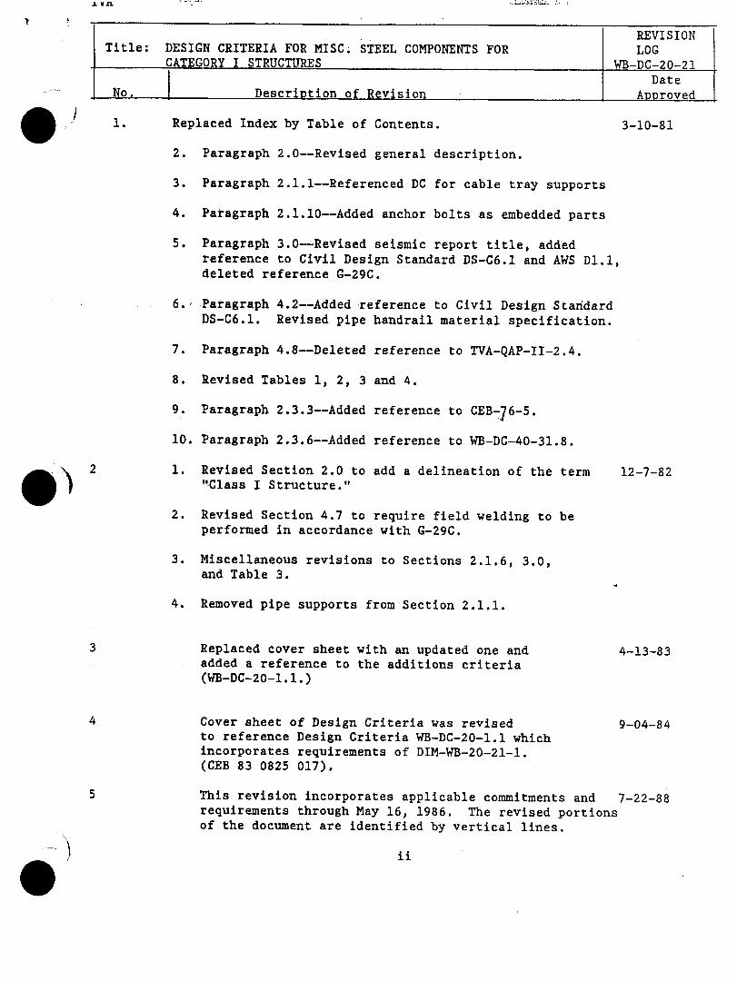
REVISIONTitle: DESIGN CRITERIA FOR MISC. STEEL COMPONENTS FOR LOG
CATEGORY I STRUCTURES WB-DC-20-21
DateNo. Description of Revision Approved
* 1. Replaced Index by Table of Contents. 3-10-81
2. Paragraph 2.0--Revised general description.
3. Paragraph 2.1.1--Referenced DC for cable tray supports
4. Paragraph 2.1.10--Added anchor bolts as embedded parts
5. Paragraph 3.0-Revised seismic report title, addedreference to Civil Design Standard DS-C6.1 and AWS D1.1,deleted reference G-29C.
.6. Paragraph 4.2--Added reference to Civil Design StandardDS-C6.1. Revised pipe handrail material specification.
7. Paragraph 4.8--Deleted reference to TVA-QAP-II-2.4.
8. Revised Tables 1, 2, 3 and 4.
9. Paragraph 2.3.3--Added reference to CEB-76-5.
10. Paragraph 2.3.6--Added reference to WB-DC-40-31.8.
12 . Revised Section 2.0 to add a delineation of the term 12-7-82"Class I Structure."
2. Revised Section 4.7 to require field welding to beperformed in accordance with G-29C.
3. Miscellaneous revisions to Sections 2.1.6, 3.0,and Table 3.
4. Removed pipe supports from Section 2.1.1.
3 Replaced cover sheet with an updated one and 4-13-83added a reference to the additions criteria(WB-DC-20-1 .1.)
4 Cover sheet of Design Criteria was revised 9-04-84to reference Design Criteria WB-DC-20-1.1 whichincorporates requirements of DIM-WB-20-21-1.(CEB 83 0825 017).
5 This revision incorporates applicable commitments and 7-22-88requirements through May 16, 1986. The revised portionsof the document are identified by vertical lines.

-'--• - Rsv:" s b
Title: DESIGN CRITERIA FOR MISC. STEL C0PONETS FOR LOG
- CATEGORY I STRUCTURES WB-DC-20-21
DateNo. Descriotion of Revision
Aooroved
5 Add Abbreviations page FA e
(Cont)Revised Sections 1.0, 2.0, 3.0, 5.0, and 7.0
Added Sections 4.0 and 6.0
Deleced Table 3.1-2
Revised Tables 5.1-1, and 5.1.-2 to add references
Added Appendix A.
6 Incorporate requirements in accordance with D!M-WB-DC-20-21-2 12-07-89
(B26 881031 034), DIM-WB-DC-20-21-3 (B26 881013 025), and
DIM-WB-DC-20-21-4 (B26 890322 021).
14 R: AA -- B26 '90 1204 828 DEC 041990
.S- 14573-A"T'1e 0i/c,, SvPersedeý DIM W6- Dr.- Zo-ZI -5 9,4
Ioncelfora 4 es cr,-,eria L,- +e evala 4 ,o,., ",,sce(arl,eo0s
ý;e r 0o ,ee,,, I 1oaJs T'he c,, 31s. revises 4-L,
4"o,.'.+ J4 Apeud, A a be csi•,1e,.,,4 .,k4, 4,ke
m~aar deu5^ cri 4 e.C~a.
"i', 21 24,7) 11, Ai, Az) A3) A+" ,,, A6= are.
P~a,ý,es ,4-.1 A4.1 k',D A,6.t. / 3-d A7 are aclle..
t~,J~ Oc4 12zwms Sto.
1 ,0o78-A
1T~ie~ DCI',) Ion~e i 3~ec-u..4-,o. A8,o -P., ±ke.
ealuakorn ^- Isrcelflaneous s-eel 4 A9er,,al IoaA5.
PA,,as LL, vtL, A(o, At..l -Lirouc,). A6.4 aie re placed. 12,pvni'ii' is
(,,A,.ItJ cmkj 61 verJ4,cal bar.
Paýe, A.•,5 , A ,a,,,d A7 pre dele4eJ.
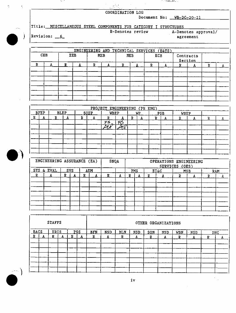
COORDINATION LOGDocument No: WB-DC-20-21
Title: MISCELLANEOUS STEEL COMPONENTS FOR CATEGORY I STRUCTURESR-Denotes review A-Denotes approval/
Revision: 6 agreement
ENGINERING AND TECHNICAL SERVICES (E&TS)CEB EEB MEB NEB ECB Contracts
SectionR A R A R A R A R A R A R A
PROJECT ENGINEERING (PR ENG)BFEP BLEP SQEP WEP WP PSB WBEPR A R A R A R A R A R A R A R A
ENGINEERING ASSURANCE (EA) DNQA OPERATIONS ENGINEERINGSERVICES (OES)
SYS & EVAL SVS ADM PMS EI&C MSB RAMR A R A R A R A R A R A R A R A
STAFFS OTHER ORGANIZATIONS
BACS ERIS PSS BF NSD BLN I NSD SON NSD WBN -NSD DNCR A R A R A R A R A R A R A R A
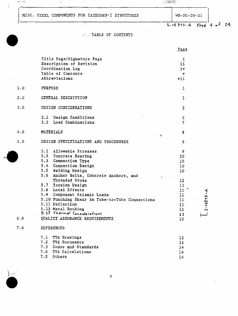
MISC. STEEL COMPONENTS FOR CATEGORY I STRUCTURES WB-DC-20-21
s- 4 3-13A f' e 4 cf 24
. ..TABLE OF CONTENTS
Page
Title Page/Signature Page iDescription of Revision iiCoordination Log ivTable of Contents vAbbreviations vii
1.0 PURPOSE 1
2.0 GENERAL DESCRIPTION 1
3.0 DESIGN CONSIDERATIONS 2
3.1 Design Conditions 23.2 Load Combinations 7
4.0 MATERIALS 8
5.0 DESIGN SPECIFICATIONS AND PROCEDURES 9
5.1 Allowable Stresses 95.2 Concrete Bearing 105.3 Connection Type 105.4 -Connection Design 10
5.5 Welding Design 105.6 Anchor Bolts, Concrete Anchors, and
Threaded Studs i5.7 Torsion Design 115.8 Local Effects 115.9 Component Seismic Loads 11 i5.10 Punching Shear in Tube-to-Tube Connections 115.11 Deflection 115.12 Metal Decking 115.13 rhernnal Co,'tsLJera•,,s 11
6.0 QUALITY ASSURANCE REQUIREMENTS 12
7.0 REFERENCES
7.1 TVA Drawings 127.2 TVA Documents 127.3 Codes and Standards 147.4 TVA Calculations 147.5 Others 14
'MISC. STEEL COMPONENTS FOR CATEGORY I STRUCTURES WB-DC-2O0--2.
516o78 -4 p-)e .TABLE OF CONTENTS (Continued)
-r%, pfe rfoled b#, Ow_• IbO.-A
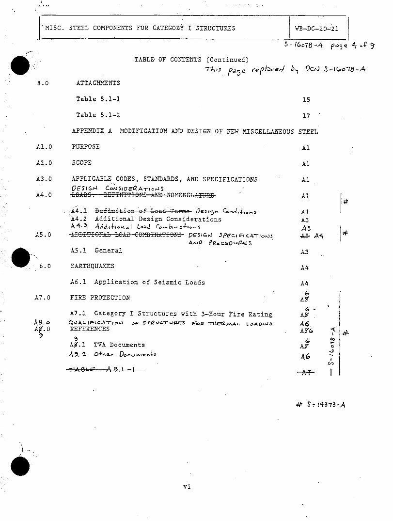
8.0 ATTACHMENTS
Table 5.1-1 15
Table 5.1-2 17
APPENDIX A MODIFICATION AND DESIGN OF NEW MISCELLANEOUS STEEL
A1.0 PURPOSE Al
A2.0 SCOPE Al
A3.0 APPLICABLE CODES, STANDARDS, AND SPECIFICATIONS Al
A4.0 LOA.DZ. DEFINTIONSAfi OICTJL Al
.:A4.1 DefinzitUon ezF Lzee Terms Oesi,5 Ce..- 1,4-,. AlA4.2 Additional Design Considerations A3A4.5 A,4j4-,.0 ,i L.)dC-o~J 4so- AB
A5 .0 ADIALLOAD CO 11bTiO~ VESI;tJ 5P'Fci Pt CArio~js 'k-3- Al
A5.1 General A3
6.0 EARTHQUAKES A4
A6.! Application of Seismic Loads A4
6A7.0 FIRE PROTECTION AO
6A7.1 Category I Structures with 3-Hour Fire Rating AF
A•.0 REFERENCES A'(o
Ay.l TVA Documents AY 0
.-5.2 O+ter- r Voj,-| __
r~5~A 0 1 f
=FAi57-

TVA
MISC. STEEL COMPONENTS FOR CATEGORY I STRUCTURES WB-DC-20-21
ABBREVIATIONS
AISC - American Institute of Steel Construction
ASCE - American Society of Civil Engineers
ASME - American Society of Mechanical Engineers
ASTM - American Society for Testing Materials
AWS - American Welding Society
DBA - Design Basis Accident
ksi - Kips per square inch
NRC - Nuclear Regulatory Commission
OBE - Operating Basis Earthquake (1/2 SSE)
PMP - Probable Maximum Precipitation
pcf - Pounds per cubic foot
psf - Pounds per square foot
psi - Pounds per square inch
SSE - Safe Shutdown Earthquake
TVA - Tennessee Valley Authority
WBNP - Watts Bar Nuclear Plant
NEP - Nuclear Engineering Procedure
ZPA - Zero Period Acceleration (Acceleration @ 33Hz)
vii
'ITVA
MISC. STEEL COMPONENTS FOR CATEGORY I STRUCTURES WB-DC-20-2l
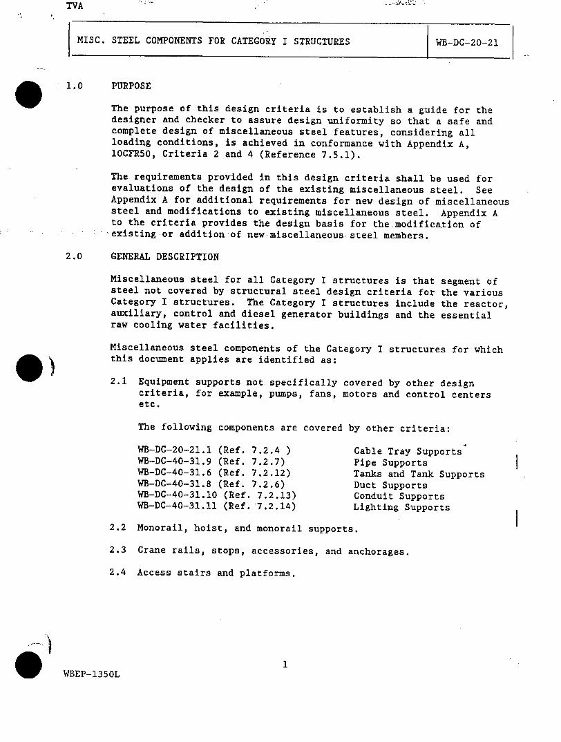
1.0 PURPOSE
The purpose of this design criteria is to establish a guide for thedesigner and checker to assure design uniformity so that a safe andcomplete design of miscellaneous steel features, considering allloading conditions, is achieved in conformance with Appendix A,lOCFR5O, Criteria 2 and 4 (Reference 7.5.1).
The requirements provided in this design criteria shall be used forevaluations of the design of the existing miscellaneous steel. SeeAppendix A for additional requirements for new design of miscellaneoussteel and modifications to existing miscellaneous steel. Appendix Ato the criteria provides the design basis for the modification of'existing or addition of new miscellaneous steel members.
2.0 GENERAL DESCRIPTION
Miscellaneous steel for all Category I structures is that segment ofsteel not covered by structural steel design criteria for the variousCategory I structures. The Category I structures include the reactor,auxiliary, control and diesel generator buildings and the essentialraw cooling water facilities.
Miscellaneous steel components of the Category I structures for whichthis document applies are identified as:
2.1 Equipment supports not specifically covered by other designcriteria, for example, pumps, fans, motors and control centersetc.
The following components are covered by other criteria:
WB-DC-20-21.1 (Ref. 7.2.4 ) Cable Tray SupportsWB-DC-40-31.9 (Ref. 7.2.7) Pipe SupportsWB-DC-40-31.6 (Ref. 7.2.12) Tanks and Tank SupportsWB-DC-40-31.8 (Ref. 7.2.6) Duct SupportsWB-DC-40-31.10 (Ref. 7.2.13) Conduit SupportsWB-DC-40-31.11 (Ref. 7.2.14) Lighting Supports
2.2 Monorail, hoist, and monorail supports.
2.3 Crane rails, stops, accessories, and anchorages.
2.4 Access stairs and platforms.
WBEP-1350L

TVA
MISC. STEEL COMPONENTS FOR.CATEGORY I STRUCTURES WB-DC-20-21
S£- 14373-A le ( o- 24
2.5 c r overs, shield plugs, access doors, and anchorages.
-6 Liner plates (sump, spent fuel pool, fuel cask loading pit, etc.)and auchorages.
2.7 Supplementary framing.
2.8 Handrail.
2.9 Grating and decking.
2.10 Miscellaneous embedded parts (frames, curbs, sleeves, supportplates, anchor bolts, etc.)
2.11 All other miscellaneous steel as required to ensure the properfunctioning of the facilities.
2.12 Category I(L) equipment supports and anchorage. Refer toWB-DC-40-64, "Design Basis Events Design Criteria" for equipmentrequiring a minimum level of seismic qualification (Reference
3.0 DESIGN CONSIDERATIONS
The reactor, control, auxiliary, and diesel generator buildings andthe essential raw cooling water facilities are Category I structures.All miscellaneous steel within or attached to these structures, whichupon failure, would result in possible damage to safety equipment,piping, ducts, and related components which are designed to remainfunctional in the event of a safe shutdown earthquake, shall bedesigned for seismic loading. The miscellaneous steel design shallconsider the effects from other attachments. The design loads'andloading combinations are defined as follows:
3.1 Design Conditions
Definition of Load Terms
The following terms are used in the load combination equations:
Normal loads, which are those loads to be encountered duringnormal plant operation and shutdown, include:
D Dead loads or their related internal moments and forces,including any permanent equipment loads, all hydrostaticloads, earth loads applied to horizontal surfaces andfireproofing.
2WBEP-1350L
MISC. STEEL COMPONENTS FOR CATEGORY I STRUCTURES WB-DC-2 0-21
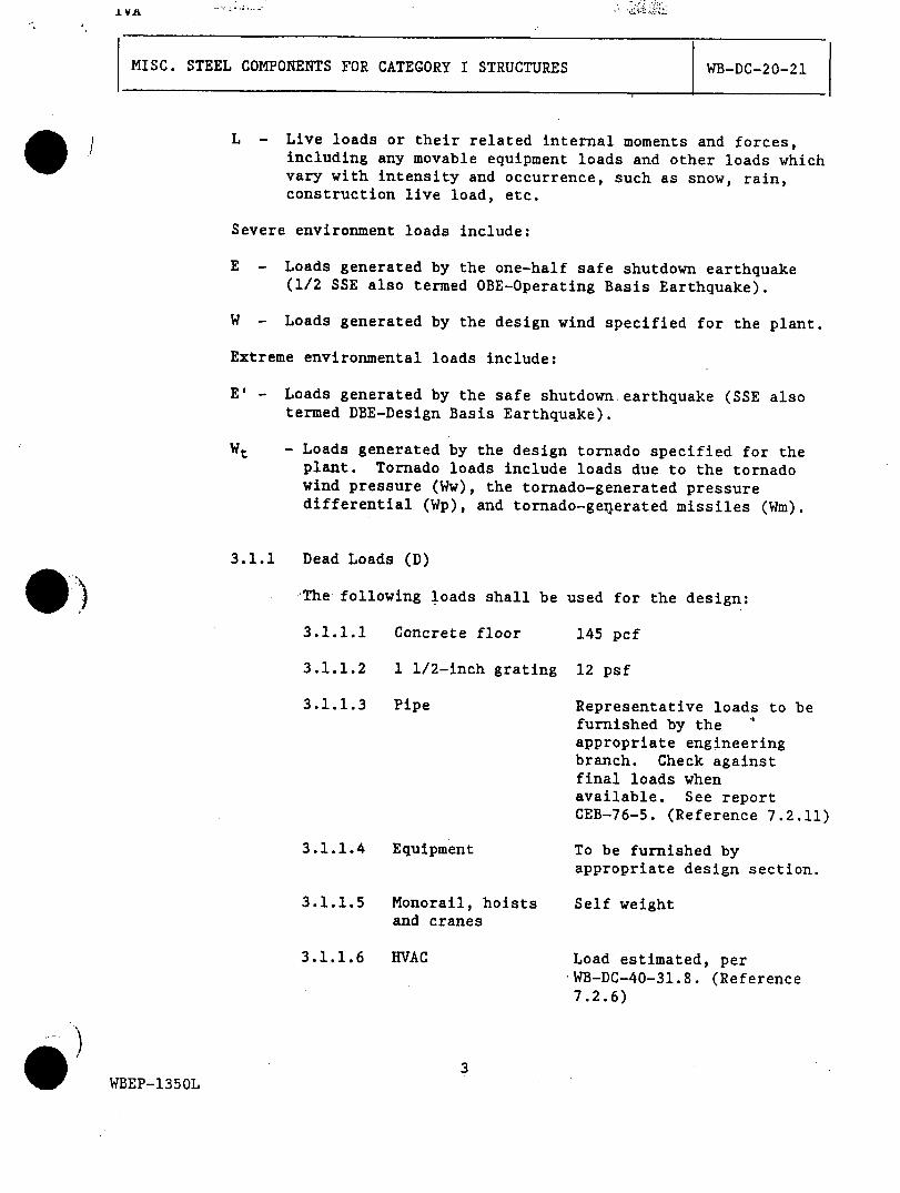
L - Live loads or their related internal moments and forces,including any movable equipment loads and other loads whichvary with intensity and occurrence, such as snow, rain,construction live load, etc.
Severe environment loads include:
E - Loads generated by the one-half safe shutdown earthquake(1/2 SSE also termed OBE-Operating Basis Earthquake).
W - Loads generated by the design wind specified for the plant.
Extreme environmental loads include:
E' - Loads generated by the safe shutdown earthquake (SSE alsotermed DBE-Design Basis Earthquake).
Wt - Loads generated by the design tornado specified for theplant. Tornado loads include loads due to the tornadowind pressure (Ww), the tornado-generated pressuredifferential (Wp), and tornado-gexlerated missiles (Wm).
3.1.1 Dead Loads (D)
The following loads shall be used for the design:
3.1.1.1 Concrete floor
3.1.1.2 1 1/2-inch grating
3.1.1.3 Pipe
3.1.1.4 Equipment
3.1.1.5 Monorail, hoists
and cranes
3.1.1.6 HVAC
145 pcf
12 psf
Representative loads to befurnished by the
appropriate engineeringbranch. Check againstfinal loads whenavailable. See reportCEB-76-5. (Reference 7.2.11)
To be furnished byappropriate design section.
Self weight
Load estimated, perWB-DC-40-31.8. (Reference
7.2.6)
WBEP-1350L
I VAlf
MISC. STEEL COMPONENTS FOR CATEGORY I STRUCTURES
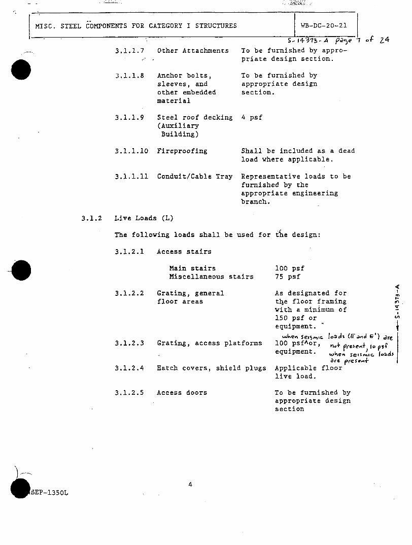
3.1.1.7 Other Attachments
3.1.1.8 Anchor bolts,sleeves, andother embeddedmaterial
3.1.1.9 Steel roof decking(AuxiliaryBuilding)
3.1.1.10 Fireproofing
3.1.1.11 Conduit/Cable Tray
To be furnished by appro-priate design section.
To be furnished byappropriate designsection.
4 psf
Shall be included as a deadload where applicable.
Representative loads to befurnished by theappropriate engineeringbranch.
3.1.2 Live Loads (L)
The following loads shall be used for t~e design:
3.1.2.1 Access stairs
Main stairs 100 psfMiscellaneous stairs 75 psf
3.1.2.2 Grating, generalfloor areas
3.1.2.3 Grating, access platforms
3.1.2.4 Hatch covers, shield plugs
3.1.2.5 Access doors
As designated fortl4e floor framingwith a minimum of150 psf orequipment. L
wt~ev% se15.¶i~c loaJs (Fa.,4 W) jrp100 psfAor, n. I ps4'equipment. Wke" sesrn,,C. 1o0ca
aepresr.4Applicable floorlive load.
To be furnished byappropriate designsection
-1350L
WB-DC-20-21
S-14-31'3-A Pve -1 of Z4
TVA
MISC. STEEL COMPONENTS FOR CATEGORY I STRUCTURES WB-DC-20-21
3.1.2.6 Handrail 200 poundsconcentrated loadat top rail formaximum condition(Reference 7.2.21).
3.1.2.7 Monorails, hoists Maximum hoist load,and cranes plus dynamic load
factor.
3.1.3 Seismic loads (E and E')
Miscellaneous structural steel shall be designed forseismic loading using the response spectra as defined inthe applicable Design Criteria (References 7.2.26 through7.2.33) and WB-DC-20-24 (Reference 7.2.15). Theappropriate damping values to use for SSE and 1/2 SSE andthe methodology for directional combinations arecontained in WB-DC-20-24 (Reference 7.2.15).
3.1.4 Environmental Conditions For The Roofs
3.1.4.1 Normal Wind (W)
The normal design wind speed is 95-mph at 30feet above grade. This is based on Figure l(b)of ASCE Paper 3269 (Reference 7.3.3), using thefastest wind speed for a 100-year period ofrecurrence. A gust factor of 1.1 is includedfor all wind loads and combinations of loadswhere wind is involved.
3.1.4.2 Tornado Wind (Ww) (Reference 7.2.16)
All Category I structures shall be designed fora "funnel" of wind having a 300-mph rotationalvelocity plus a 60-mph translational velocity.This includes individual members which areexposed during a tornado. A dynamic pressureload of 1.3q shall be applied to the roof(Reference 7.3.3). Where the dynamic windpressuure, q is defined as q = 0.00256V 2,with q in psf and V is wind velocity in mph.
5WBEP-1350L

.L Va
MISC. STEEL COMPONENTS FOR CATEGORY I STRUCTURES WB-DC-20-21
3.1.4.3 Tornado Depressurization (Wp)
All Category I structures shall be designed foran external despressurization of 3 psioccurring in 3 seconds. The resulting possible3-psi pressure differential between the insideand outside of the structures may be reduced byventing. Where venting is used, the interiorstructural members shall be investigated anddesigned for the 3 psi pressure whereapplicable.
3.1.4.4 Missiles (Wm)
Missiles which the miscellaneous steel roofmust withstand are listed in WB-DC-40-65,"Missiles" (Reference 7.2.17).
3.1.4.5 Snow
The maximum probable snow load is 20 pounds persquare foot (psf).
3.1.4.6 Rainfall
The normal rainfall (4 in/hr) a conventionalroof drain and downspout system will dischargeroof runoff into the yard drainage system.However, during the local Probable MaximumPrecipitation (PMP), as discussed inWB-DC-40-1, "Roof Drainage Systems" (Reference7.2.24), one or more of the following methodsshall be used to prevent buildup of stafidingwater on the roofs of safety-related buildings.
a. The parapets may be deleted on one or moresides of the building.
b. The parapet height may be limited topreclude buildup of water in excess of thestructural capacity of the roof for thedesign live loads on the roof.
c. Scuppers may be installed through theparapets to discharge the standing waterover the edge of the building.
3.1.5 Miscellaneous steel in the steel containment vessel shallbe designed for additional dynamic loads produced by DBApressure transients. Response acceleration spectra areemployed to compute dynamic response in the same manneras for seismic effects.
6WBEP-1350L

.j. V
S- 1+313 -A eQe 8 2. 4
-.2 Load Combinations
Yor service load conditions, the elastic working stress designmethods of part I of AISC Specification (Reference 7.3.1) shallbe used and the following load combinations shall be considered.
3.2.1 Load Combinations for Miscellaneous Steel Other ThanCategory I(L) Equipment Supports
Move .. Fbe Service loadAllowable Stress Load Combinations
(1) AISC Allowable* D + L
(2) AISC Allowable* D + L + E
(3) AISC Allowable* D + L + W
The 33 percent increase in allowable stresses for steeldue to seismic or wind loadings that is allowed by AISC(Reference 7.3.1) is not permitted.
For factored load conditions, the fo.lowing loadcombinations shall be considered:
Allowable Stress Load Combinations
(4) 1.6 x AISC Allowable* D + L +'E'
(5) 1.6 x AISC Allowable* D + L + Wt ,
*See Table 5.1-1 for limiting values
Thermal loadings shall be identified and demonstratedto be self limiting and secondary in nature. Theeffects of pipe rupture including pressure, impact, jetimpingment, missiles and flood shall be designed inaccordance with WB-DC-40-31.51, "Evaulating the Effectsof Flooding Due to Moderate Energy Pipe Failures Insideand Outside Containment" (Reference 7.2.22),WB-DC-40-31.53, "Pipe Whip Restraints, Jet Deflectorsand Sleeves" (Reference 7.2.8) and WB-DC-40-31.50,"Evaluating the Effects of a Pipe Failure Inside andOutside Containment" (Reference 7.2.25).
3.2.2 Load Combinations for Miscellaneous Steel Used asCategory I(L) Equipment Supports
For service load conditions, the elastic working stressdesign methods of Part 1 of AISC specifications(Reference 7.3.1) shall be used and the load
7TBEP-1350L
TVA
MISC. STEEL COMPONENTS FOR CATEGORY I STRUCTURES WB-DC-20-21
combinations (1), (3), (4) and (5) as discussed inSection 3.2.1 shall be considered.
4.0 MATERIALS
In general, the materials shall conform to the followingspecifications unless other types of steel are required by design:
Structural shapes, platesand bars
Structural tubing
Structural pipe
Aluminum plates and shapes
Stainless steel plates
Plates and bars for trashracks
High-strength bolts
Anchor bolts
Weld rods
Stainless steel weld rods
Pipe handrail
Bolt anchors
Headed concrete anchors
Threaded studs
ASTM A36
ASTM A501 or A500, Grade B
ASTM A53, Grade B
Alloy 6061-T6
ASTM A167, Type 304
ASTM A36, with 0.2% minimumcopper or ASTM A441
7/8 inch diameter,ASTM A325, except where othersizes or higher strength maybe required for heavy loadsor special connections.
ASTM A307 or A36.
AWS A5.1, E70 or E60 Series,as applicable, or others asrequired for materialcompatability (Reference7.3.2).
AWS A5.4, E308 Series
ASTM A120 or A36
Manufacturer's standardquality.
ASTM A108, Grade 1015 through1020.
ASTM A108
WBEP-1350L

TVA
MISC. STEEL COMPONENTS FOR CATEGORY I STRUCTURES
Steel grating (painted orgalvanized)
Aluminum grating (not to beused in reactor building)
Metal Deck
Stainless steel grating(to be used in ReactorBuilding only)
WB-DG-2 0-21
Manufacturer's standardquality
Manufacturer' s standardquality
Manufacturer's standardquality
ASTM A167, type 304 or 316ASTM A240, type 304 or 316
5.0 DESIGN SPECIFICATIONS AND PROCEDURES
5.1 Allowable Stresses
5.1.1 Miscellaneous Steel Other Than Category I(L) EquipmentSupports
Structural steel and welds are designed for Cases (1),(2), and (3) loading conditions so that the stress inthe members and connections do not exceed the allowablestress criteria as set forth in AISC specifications(Reference 7.3.1).
For Cases (4) and (5) loading conditions, the actualstresses shall not exceed the allowable stresses as setforth in Table 5.1-1.
5.1.2 Miscellaneous Steel Used as Category I(L) EquipmentSupports
Structural steel and welds are designed for Cases (1)and (3) loading conditions so that the stress in themembers and connections do not exceed the allowablestress criteria as set forth in AISC specifications(Reference 7.3.1).
For Cases (4) and (5) loading conditions,.the-actualstresses shall not exceed the allowable stresses as setforth in Table 5.1-1.
5.1.3 Anchorage for Missile Shield and Hatches in the DividerBarrier of Reactor Building
9WBEP-1350L
mL)
TVA
MISC. STEEL COM4PONENTS FOR CATEGORY I STRUCTURES WB-DC-20-21
Special considerations have been taken of the allowableunit stresses in the anchorages for the missile shieldand hatches in the divider barrier of the reactorbuilding. These allowable unit stresses shall belimited since it is not feasible to pressure test thedivider barrier. The allowable unit stresses shall beAISC working stress under conditions of loadinginvolving dead load, operating loads, design basisaccident, and one-half safe shutdown earthquake. Whenthe loading conditions result from a combination ofdead load, operating loads, design basis accident, andsafe shutdown earthquake, the loads shall be increasedby 5 percent and the allowable unit stresses shall belimited to 80 percent of those normally permitted. Theanchorages for the missile shields and hatches aredesigned for the end reactions per WB-DC-20--2(Reference 7.2.29) and WB-DC-40-60 (Reference 7.2.9)respectively, increased by 5 percent as noted above.
5.2 Concrete Bearing
Allowable bearing pressure of concrete shall be 1125 psi forinterior columns, 900 psi for columns near joints, and 750 psifor wall columns and beam base plates.
)5.3 Connection Type
All connections and assemblies of miscellaneous steel shall bewelded except where bolted connections are required or are morepractical as determined by the supervisor.
5.4 Connection Design
All beams where bolted connections are required shall be providedwith the AISC Table I (Reference 7.3.1) framed beam connectionwith the maximum rows of bolts unless a heavier connection is-required. An acceptable connection design is provided inDG-Cl.6.4 (Reference 7.2.10).
5.5 Welding Design
Unless otherwise noted by other specific design criteria,,allwelds shall be designed per AISC Specifications (Reference 7.3.1).
All field welding shall be performed in accordance with TVAGeneral Construction Specification G-29 (Reference 7.2.2), unlessotherwise specified.
All welds to the steel containment vessel shall conform to the) requirements of ASME Section III (Reference 7.3.5).
10WBEP-1350L
I . --ýTVA
MISC. STEEL COMPONENTS FOR CATEGORY I STRUCTURES WB-DC-20-21
S.14 13-A A9 o
Existing welds which do not meet the minimum size requirements inlc 1.1.7.5 of the AISC Specification (Reference 7.3.1) but
wh:Vh meet allowable stress requirements may be qualified inaccordance with the provisions contained in paragraph 1.17.2 ofthe AISC Specification..
5.6 Anchor Bolts, Concrete Anchors, and Threaded Studs
Civil Design Standard DS-Cl.7.1 (Reference 7.2.3) shall be usedfor the design of concrete bolt anchors and headed concreteanchors.
5.7 Torsion Design
Torsional Stresses induced by eccentric loads shall be consideredfor the design of the miscellaneous steel. This design shall bein accordance with AISC (Reference 7.3.1) and Civil Design GuideDC-CI.6.7, "Design of Structural Steel Members, (buildings,miscellaneous steel and supplementary steel)" (Reference 7.2.1).
5.8 Local Effects
Miscellaneous steel shall be evaluated for local effects atconnections and attachment locations. Stiffeners shall beprovided where required.
5.9 Component Seismic Loads
All components of seismic loads from pipe, HVAC and electricalsupport group shall be considered in the miscellaneous steeldesign.
5.10 Punching Shear in Tube-to-Tube Connections
Miscellaneous steel tube-to-tube welded connections shall bedesigned for punching shear in accordance with AWS D1.1-81,Section 10.5, or later revisions of the section (Reference 7.3.4).
5.11 Deflection
Deflection criteria for miscellaneous steel (including theeffects of ponding) shall be in accordance with AISCSpecification (Reference 7.3.1).
5.12 Metal Decking
Metal decking shall be designed in accordance with therecommended procedure of each manufacturer using themanufacturer's section material properties for the decking.
5.Q3 rherrna l iaea~ei J
WBEP-1350L awaluaa4 mo r $oA er, effec43 ,Il be ,n accordance
wfh 3ec4son Ae.O.
TVA
MISC. STEEL COMPONENTS FOR CATEGORY I STRUCTURES WB-DC-20-21
b ) 6.0 QUALITY ASSURANCE REQUIREMENTS
Structures/Systems which perform a safety-related function or have
seismic requirements must have quality assurance applied in thedesign, procurement, and testing of the structure/system andstructure/system components.
The following documents further clarify TVA's QA requirements.
a. TVA Topical Report TVA - TR75-1A, Quality Assurance (Reference7.2.18).
b. Nuclear Quality Assurance Manual, (NQAM) (Reference 7.2.19).
c. DNE Nuclear Engineering Procedures (NEP) Manual (Reference7.2.20).
7.0 REFERENCES
7.1 TVA Drawings (none)
7.2 TVA Documents
7.2.1 DG-Cl.6.7, "Design of Structural Steel Membersp !) (buildings, miscellaneous steel and supplementary steel)"
7.2.2 TVA Construction Specification G-29, "ProcessSpecifications for Welding, Heat Treatment,Nondestructive Examination, and Allied Field FabricationsOperations."
7.2.3 DS-Cl.7.1, "General Anchorage to Concrete"
7.2.4 Design Criteria WB-DC720-21.1, "Category I Cable TraySupports"
7.2.5 Design Criteria WB-DC-20-22, "Miscellaneous ConcreteCategory I Yard Structures"
7.2.6 Design Criteria WB-DC-40-31.8, "Seismically QualifyingRound and Rectangular Ducts"
7.2.7 Design Criteria WB-DC-40-31.9, "Location and Design ofPiping Supports and Supplemental Steel in Category IStructures"
7.2.8 Design Criteria WB-DC-40-31.53, "Pipe Whip Restraints,Jet Deflectors and Sleeves"
7.2.9 Design Criteria WB-DC-40-60, "Special Hatches and Manways"
WBEP-1350L
* TVA
MISC. STEEL COMPONENTS FOR CATEGORY I STRUCTURES WB-DC-20-21
7.2.10 DG-Cl.6.4, "Design of Structural Connections"
7.2.11 TVA Report CEB-76-5
7.2.12 Design Criteria WB-DC-40-31.6, "Seismically QualifyingTanks and Reservoirs, and Their Supports"
7.2.13 Design Criteria WB-DC-40-31.10, "Support of Conduits inCategory I Structures"
7.2.14 Design Criteria WB-DC-40-31.11, "Support of LightingFixtures in Category I Structures"
7.2.15 Design Criteria WB-DC-20-24, "Dynamic Earthquake Analysisof Category I Structures and Earth Embankments"
7.2.16 DG-Cl.3.4, "Loads and General Provisions Extreme Wind and
Tornado Forces on Structures"
7.2.17 Design Criteria WB-DC-40-65, "Missiles"
7.2.18 TVA Topical Report TVA-TR75-1A "Quality Assurance"
7.2.19 Nuclear Quality Assurance Manual (NQAM)
7.2.20 DNE Nuclear Engineering Procedures (NEP) Manual
7.2.21 TVA Occupational Health and Safety Manual
7.2.22 Design Criteria WB-DC-40-31.51, "Evaluating the Effectsof Flooding Due to Moderate Energy Pipe Failure Insideand Outside Containment"
7.2.23 Deleted
7.2.24 Design Criteria WB-DC-40-1, "Roof Drainage Systems"
7.2.25 Design Criteria-WB-DC-40-31.50, "Evaluating the Effectsof a Pipe Failure Inside and Outside Containment"
7.2.26 Design Criteria WB-DC-20-9, "Control Building StructuralSteel"
7.2.27 Design Criteria WB-DC-20-10, "Auxiliary BuildingStructural Steel"
7.2.28 Design Criteria WB-DC-20-1.1, "Additional DieselGenerator Building and New Category I Structures"
) 7.2.29 Design Criteria WB-DC-20-2, "Reactor Building ConcreteStructure"
13WBEP-1350L

TVA
MISC. STEEL COMPONENTS FOR CATEGORY I STRUCTURES WB-DC-20-21
) 7.2.30 Design Criteria WB-DC-20-3, "Reactor Building ContainmentVessels - Structural Steel"
7.2.31 Design Criteria WB-DC-20-8, "Auxiliary-Control BuildingConcrete Structures"
7.2.32 Design Criteria WB-DC-20-17, "Diesel Generator BuildingConcrete Structure"
7.2.33 Design Criteria WB-DC-20-19, "Intake Pumping StationConcrete Structure, Intake Channel and Retaining Walls"
7.2.34 Design Criteria WB-DC-40-64, "Design Basis Events DesignCriteria"
7.3 Codes and Standards
7.3.1 AISC Specification for the Design, Fabrication, andErection of Structural Steel for Buildings 1969 edition,as amended through June 12, 1974.
7.3.2 AWS, D1.1-72, "Structural Welding Code" as modified byTVA General Construction Specification G-29
7.3.3 ASCE Paper 3269, "Wind Forces on Structures."
7.3.4 AWS, DI.1-81, "Structural Welding Code"
7.3.5 ASME Boiler and Pressure Vessel Code Section II, III, andVIII, 1971, Winter Addenda, and applicable sectionsrequired for a Class MC nuclear vessel
7.4 TVA Calculations
7.4.1 Calculation for Allowable Stress for Safe ShutdownEarthquake for Compression Members - Table 5.1-2 (Later)
7.5 Others
7.5.1 NRC General Design Criteria (GDC) Appendix A to 10CFR50,July 1971.
')14
WBEP-1350L

MISC. STEEL COMPONENTS FOR CATEGORY I STRUCTURES
TABLE 5.1-i
LoadingConbinations Tension Shear Compression Bendi
(1), (2), (3) 0.60 Fy 0.40 Fy See Note 1 See N
(la) (2a), (3a) 0.90 Fy 0.90 Fy See Note 2 0.90(4) thru (10)
Note 1 - Varies with slenderness ratio, see AISC "Manual of SteelConstruction," 7th Edition, Table 1-36, Page 5-84 (Referen
Note 2 - Varies with slenderness ratio (see Table 5.1-2):
Note 3 - varies, see Section 1.5.1.4 of Reference 7.3.1 on bending.
Main and secondary members where KL/R < Cc:
(K/r) 2Fa = 0.9 Fy 1 -
2Cc 2 (A)
Main members where Cc <KL/r<200: Fa = 0.912 E
(KL/r)2 (B)
Secondary
Fas
ng
ote 3
Fy
ce 7.3.1).
members where 120 < L/r < 200
- Fa [by Formula (A) or (B)]1.6 - L/200r
Where:
I2,12 E
- Modulus of elasticity of steel
- Axial compressive stress permitted in the absence of bendingmoment (kips per square inch)
Axial compressive stress, permitted in the absence of bendina mo-ment, for bracing and other secondary members (kips per squareinch)
15
qB-DC-20-21
MISC. STEEL COMPONENTS FOR CATEGORY I STRUCTURES WB-DC-20-21
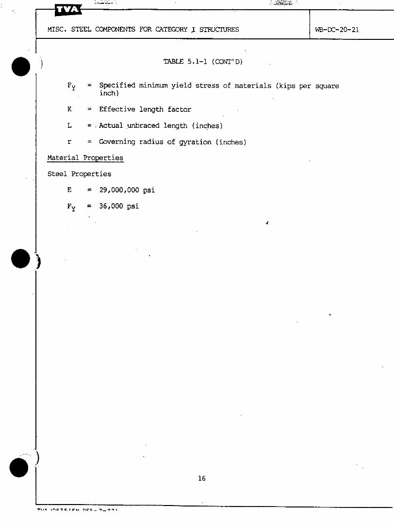
TABLE 5.1-1 (CONT'D)
Fy = Specified minimum yield stress of materials (kips per square
inch)
K = Effective length factor
L = Actual unbraced length (inches)
r = Governing radius of gyration (inches)
Material Properties
Steel Properties
E = 29,000,000 psi
Fy = 36,000 psi
*Y*\n in 'A I roa nrc~ - %
'C
MISC. STEEL COMPONENTS FOR CATEGORY .I STRUCTUJRES WB-DC-20-21
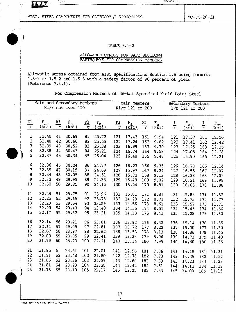
TABLE 5.1-2
ALLOWABLE STRESS FOR SAFE SHUTDOWNEARTHQUAKE FOR COMPRESSION MEMBERS
Allowable stress obtained from AISC Specifications Section 1.5 using formula1.5-1 or 1.5-2 and 1.5-3 with a safety factor of 90 percent of yield(Reference 7.4.1).
For Compression Members of 36-ksi Specified Yield Point Steel
Main and Secondary Members Main Members Secondary MembersKl/r not over 120 Kl/r 121 to 200 1/r 121 to 200
Kl Fa K1 Fa K1 Fa Kl Fa K1 Fa 1 Fas 1 Fasr (ksi). r (ksi) r (ksi) r (ksi) r (ksi) r (ksi) r (ksi)
32.4032.4032.3932.3832.37
32.3632.3532.3432.3232.30
32.2832.2532.2332.2032.17
32.1432.1132.0732.0331.99
31.9531.9131.8631.8131.76
30.6930.6030.5230.4330.34
30.2430.1530.0529.9529.85
29.7529.6529.5429.4329.32
29.2129.0928.9728.8528.73
28.6128.4828.3628.2328.10
8182838485
8687888990
9192939495
96979899
100
101102103104105
25.7225.5525.3825.2125.04
24.8724.6924.5124.3324.15
23.9623.7823.5923.4023.21
23.0122.8122.6222.4122.21
22.0121.8021.5921.3821.17
121122123124125
126127128129
130
131132133134135
136137138139140
141142143144145
17.4317.2416.9916.7416.48
16.2315.9715.7215.4815.24
15.0114.7814.5614.3514.13
13.9313.7213.5313.3313.14
12.9612.7812.6012.4212.25
161162163164165
166167168169170
171172173174175
176177178179180
181182183184185
9.949.829.709.589.46
9.359.249.139.028.91
8.818.718.618.518.41
8.328.228.138.067.95
7.867.787.697.617.53
121122123124125
126127128129130
131132133134135
136137138139140
141142143144145
17.5717.4117.2517.0816.90
16.7316.5516.3816.2116.05.
15.8815.7315.5715.4315.28
15.1415.0014.8614.7314.60
14.4814.3514.2314.1214.00
161162163164165
166167168169170
171172173174175
176177178179180
181182183184185
12.5012.4212.3512.2812.21
12.1412.0712.0111.9511.88
11.8211.7711.7111.6611.60
11.5511.5011.4511.4011.36
11.3111.2711.2311.1911.15
TV5 I 1,.VPW rW--7.-*77
MISC. STE
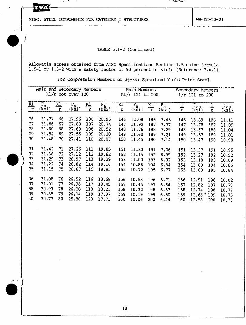
TABLE 5.1-2 (Continued)
Allowable stress obtained from AISC1.5-1 or 1.5-2 with a safety factor
Specifications Section 1.5 using formulaof 90 percent of yield (Reference 7.4.1).
For Compression Members of 36-ksi Specified Yield Point Steel
Main and Secondary Members Main Members Secondary MembersKl/r not over 120 Kl/r 121 to 200 1/r 121 to 200
K1 Fa K1 Fa 1( Fa Ki Fa K1 Fa 1 Fas 1 Fasr (ksi) r (ksi) r (ksi) r (ksi) -r (ksi) r (ksi) r (ksi)
31.71 6631.66 6731.60 6831.54 6931.48 70
31.42 7131.36 7231.29.7331.22 7431.15 75
31.08 7631.01 7730.93 7830.85 7930.77 80
27.9627.8327.6927.5527.41
27.2627.1226.9726.8226.67
26.5226.3626.2026.0425.88
106107108109110
ill112113114115
116117118119120
20.9520.7420.5220.3020.07
19.8519.6219.3919.1618.93
18.6918.4518.2117.9717.73
146147148149150
151152153154155
156157158159160
12.0811.9211.7611.6011.45
11.3011.1511.0010.8610.72
10.5810.4510.3210.1910.06
186187188189190
191192193104195
196197198199200
7.457.377.297.217.14
7.066.996.926.846.77
6.716.646.576.506.44
146147148149150
151152153154155
156157158159160
13.8913.7813.6713.5713.47
13.3713.2713.1813.0913.00
12.9112.8212.7412.6612.58
186187188189190
191192193154195
196197198199200
11.1111.0511.0411.0110.98
10.9510.9210.8910.8610.84
10.8210.7910.7710.7510.73
WB-DC-20-21EL COMPONENTS FOR CATEGORY I STdJCTURES
MISC. STEEL COMPONENTS FOR CATEGORY I STRUCTURES WB-DC-20-21
S- 143'75 -A P Jo 10 Z4APPENDIX A
MODIFICATIONS AND NEW DESIGNOF MISCELLANEOUS STEEL COMPONENTS OF
CATEGORY I STRUCTURES
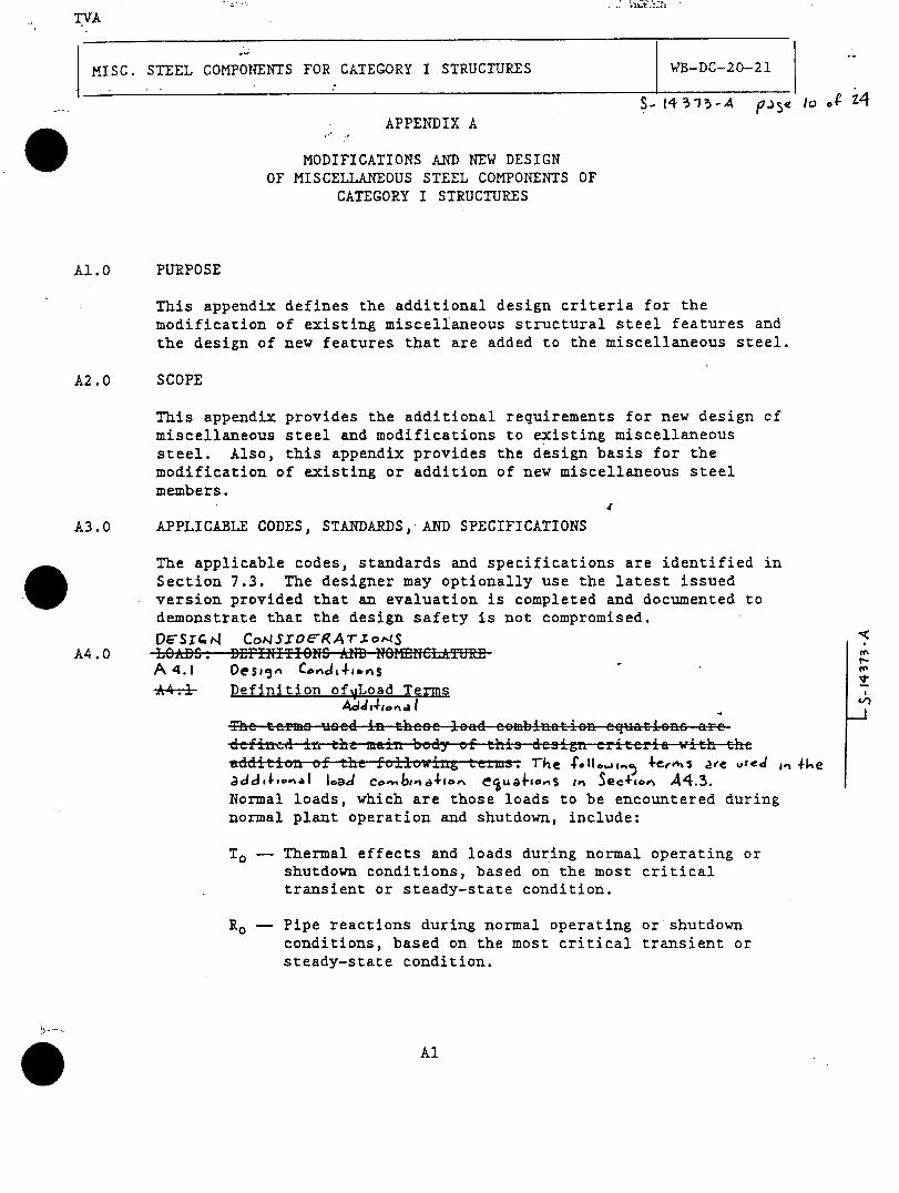
A1.0 PURPOSE
This appendix defines the additional design criteria for themodification of existing miscellaneous structural steel features andthe design of new features that are added to the miscellaneous steel.
A2.0 SCOPE
This appendix provides the additional requirements for new design cfmiscellaneous steel and modifications to existing miscellaneoussteel. Also, this appendix provides the design basis for themodification of existing or addition of new miscellaneous steelmembers.
A3.0 APPLICABLE CODES, STANDARDS, AND SPECIFICATIONS
The applicable codes, standards and specifications are identified inSection 7.3. The designer may optionally use the latest issuedversion provided that an evaluation is completed and documented to
demonstrate that the design safety is not compromised.
06-SI~i4 CoN.SX06*RATrXot-1SA4.0 LOAD.S DEFINITIONS AlD NO1MNCLATU- oE
A 4.1 Oes,5" Cnd&ý,AS
44-: Definition ofqLoad Terms 7Acd , 4 ,o n . I __
The termso used in these lead eembinatien equationz arc--,d in tha mai body of this design criteria with the
addition of the folloinz terms- 1"he 4-teo, are vied I, ike
acJ,.I,.,i.8I load co.4 b,.i4-,ov% e ,sua1-,.is ,IV See+,*o, A4.3.Normal loads, which are those loads to be encountered duringnormal plant operation and shutdown, include:
To - Thermal effects and loads during normal operating orshutdown conditions, based on the most criticaltransient or steady-state condition.
Ro - Pipe reactions during normal operating or shutdownconditions, based on the most critical transient orsteady-state condition.

TVA
MISC. STEEL COMPONENTS FORCATEGORY I STRUCTURES WB-DC-20-21
Abnormal loads, which are those loads generated by a
po!-.::ulated high-energy pipe break accident, include:
Thermal loads under thermal conditions generated by the
postulated break and including To .
Ra - Pipe reactions under thermal conditions generated by
the postulated break including Ro .
Pa- Pressure equivalent static load within or across a
compartment generated by the postulated break and
including an appropriate dynamic load factor to account
for the dynamic nature of the load.
Yr- Equivalent static load on the structure generated by
the reaction on the broken high-energy pipe during the
postulated break and including an appropriate dynamic
load factor to account for the dynamic nature of the
load.
Yj - Jet impingement equivalent static load on a structuregenerated by the postulated break and including anappropriate dynamic load factor to account for thedynamic nature of the load.
Ym - Missile impact equivalent static load on a structuregenerated by or during the postulated break, as frompipe whipping, and including an appropriate dynamicload factor to account for the dynamic nature of theload.
In determining an appropriate equivalent static load forYr, Yj, and Ym, elastoplastic behavior may be assumed.with appropriate ductility ratios, provided excessive
deflections will not result in loss of function of anysafety-related system
Other loads include:
F - Hydrostatic load from the design basis flood
Fa -- Flood load generated by a postulated pipe break <C
Any loads resulting from a postulated explosion shall bedetermined on a case-by-case basis.
Tornado wind loads, etc., can be determined by the methods ofReference AZ.l.l.
9
MISC. STEEL CPMr.,BS FOR CATEGORY ISTRUCTURES B-EC-20-21
14-3143-A pa~e 1Z.-oF Z4
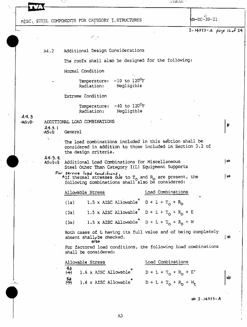
A4.2 Additional Design Considerations
The roofs shall also be designed for the following:
Normal Condition
Temperature: -10 to 1200FRadiation: Negligible
Extreme Condition
Temperature: -40 to 120°FRadiation: Negligible
A4.3A. ADDITIONAL LOAD CCOBINATIONS
A,4.3. i1-+.- General
The load combinations included in this se'ction shall beconsidered in addition to those included in Section 3.2 ofthe design criteria.
ý6.1.1 Additional Load Combinations for MiscellaneousSteel Other Than Category I(L) Equipment Supports
For Service Ioad co,,,d,1 4-,v
AIf thermal stresses dde to To and R. are present, the
following combinations shall also be considered:
Allowable Stress Load Combinations
(1a) 1.5 x AISC Allowable D + L +
(2a) 1.5 x AISC Allowable D + L + To + Ro + E
(3a) 1.5 x AISC Allowable D + L + To + Ro + W
Both cases of L having its full value and of being conpletelyabsent shallvbe checked. j T
alsoFor factored load conditions, the following load ccmbinationsshall be considered:
Allowable Stress Load Combinations
4a *
(4) 1.6 x AISC Allowable D + L + To + R0 + E'59 ..(-5" 1.6 x AISC Allowable D + L + To + Ro + Wt
w S -5147 3-A

TVA
MISC. STEEL COMPONENTS FOR CATEGORY I STRUCTURES WB-DC-20-21
(6) 1.6 x AISC Allowable*
(7) 1.6 x AISC Allowable*
(8) 1.7 x AISC Allowable*
(9) 1.6 x AISC Allowable*
(10) 1.6 x AISC Allowable*
ýD + L + Ta + Ra + Pa
D + L + Ta + Ra + Pa +1.0 (Yj + Yr + Ym) + E
D + L + Ta + Ra + Pa +1.0 (Yj + Yr + Ym) + E'
D + Fa
D+F
*See Table 5.1-1 for limiting values.
A4.3.3 AJdJI4ovalA5.1.2 ALoad Combinations for Miscellaneous Steel Used as Category I(L)
Equipment Supports
If thermal stresses due to To and R. are present, the loadcombinations discussed in Section *5.1.1 are applicable exceptload combination (2a). A4.3.-2,
As.o DSISGN SPECAFICATIOJS A4O PR&CEOUIRCE SELF PACG A4.IA6.0 EARTHQUAKES
A6.1 Application of Seismic Loads
To develop loads generated by the earthquake, the designer shallperform one of the following analysis methods:
-n the abeve load eembinaticns, thermal leads cain be neglectedn t can be shown that they are secondary and seif-limitin n
natu and where the material is ductile. The judgments ajustifi. c ions for neglecting thermal loads must be do ented inthe calcula ns
In the combination 6), (7), and (8), the imum values of
Pa, Ta, Ra, Yj, Yr, an Ym, including an' propriatedynamic load factor, shal e used u-n ss a time-history analysisis performed to jus tify o he e Combinations (5), (7), and(8) should be first satisfied ut the tornado missile load in(5).and without Yr, Yj, m in ( ad (8). Whenconsidering these conc rated loads, s sses may exceed maximumallowable stresses 'yen in Table 5.1-1. S References 7.2.22,7.2.8 and 7.2.2
Where D L reduce the effect of the loads given abd thecorr onding coefficients shall be taken as 0.90 D ad z forL The vertical pressure of liquids shall be considered as d
S- 1+313-A paý, 13,, f Z+
I
•A ... .. L-

TVA
MISC. STEEL
-2 r,!n, A r 5~ e d 1 ? 0
COMPONENTS FOR CATEGORY I STRUCTURES
r .T
WB-DC-20-21
A5./
(7) 1.6 x C Allowable* D 4 L + Ta + Ra + Pa +1.0 (Yj + Yr +
(8) 1.7 x AISC Allowable D + L a + Ra + Pa +1. ~CJ~ + Yr+ Yin) + E'
(9) 1.6 x AISC Allowab•- D + Fi
(10) 1.6 C Allowable* D f+r F
_ee ýTable 5,1-1 for limitinp values--.- - ~-3P~rnA '1ad PreceJ.fe-r '4 Se.A,6.., 4.3.2- _J~aIJ 3rIn the -&be..e. load combinationsi thermal loads can beA^Ieg4e.-.e.-when it can be. shown that they are secondary and self-limiting innature and where the material is ductile. The judgments andjustifications for neglecting thermal loads must be documented inthe calculations.
A S. _ In the combinations (6), (7), and (8), the maximum values ofPa, Ta, Ra, Yj, Yr, and Ym, including an ippropriatedynamic load factor, shall be used unless a time- story analysisis performed to Justify otherwise. Combinations M , (7), and(8) should be first satisfied without the tornado missile load in
5@-t) and without Yr, Yj, and Ym in .(7) and (8). Whenconsidering these concentrated loads, stresses may exceed maximumallowible stresses given in Table 5.1-1. See References 7.2.22,7.2.8 and 7.2.25.
A5,5 Where D or L reduce the effect of the loads given above, thecorresponding coefficients shall be taken as 0.90 D and zero forL. The vertical pressure of liquids shall be considered as deadload with due regard to variation in liquid depth.
A4, I
-rh,5 fs e 2cic aded b c 3 4-1-cci 3 - 0- -3 -7-3 - A
ý , I A 1-2 11 1
.TVA
MISC. STEEL COMPON~ENTS FOR CATEGORY I STRUCTURES WB-DC-20-21
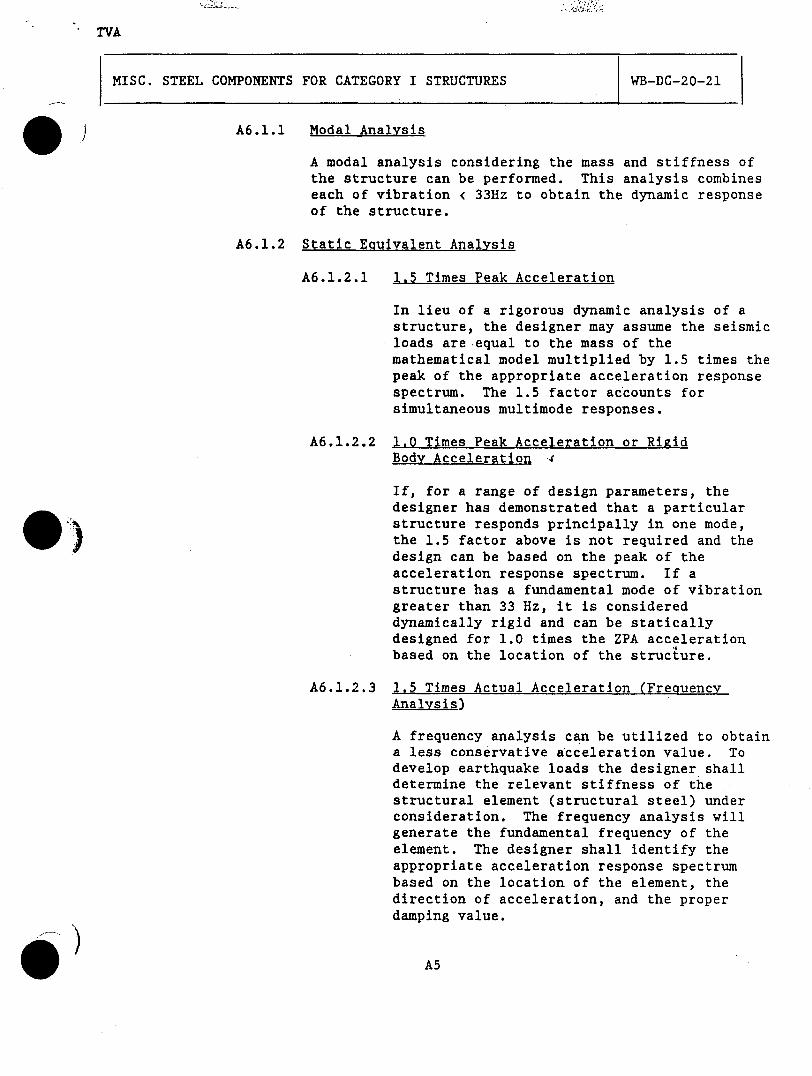
)A6.1.1 Modal Analysis
A modal analysis considering the mass and stiffness ofthe structure can be performed. This analysis combineseach of vibration <~ 33Hz to obtain the dynamic responseof the structure.
A6.1.2 Static Equivalent Analysis
A6.1.2.1 1.5 Times Peak Acceleration
In lieu of a rigorous dynamic analysis of astructure, the designer may assume the seismicloads are equal to the mass of themathematical model multiplied by 1.5 times thepeak of the appropriate acceleration responsespectrum. The 1.5 factor accounts forsimultaneous multimode responses.
A6.1.2.2 1.0 Times Peak Acceleration or RigidBody Acceleration .i4
If, for a range of design parameters, thedesigner has demonstrated that a particularstructure responds principally in one mode,
K) the 1.5 factor above is not required and thedesign can be based on the peak of theacceleration response spectrum. If astructure has a fundamental mode of vibrationgreater than 33 Hz, it is considereddynamically rigid and can be staticallydesigned for 1.0 times the ZPA accelerationbased on the location of the structure.
A6.1.2.3 1.5 Times Actual Acceleration (FrequencyAnalysis)
A frequency analysis can be utilized to obtaina less conservative a~cceleration value. Todevelop earthquake loads the designer shalldetermine the relevant stiffness of thestructural element (structural steel) underconsideration. The frequency analysis willgenerate the fundamental frequency of theelement. The designer shall identify theappropriate acceleration response spectrumbased on the location of the element,. thedirection of acceleration, and the properdamping value.

TVA,S -1(d08 --A Pjc 5 -f -P
MISC. STEEL COMPONENTS FOR:CATEGORY I STRUCTURES
.OC -1 o-7 S -A
WB-DC-20-21
The designer shall then use the appropriateacceleration response spectrum curve todetermine the earthquake acceleration (g) to
be applied based on the fundamental frequencyobtained. The designer shall includeconsideration of the effects of theparticipation of higher modes by multiplyingthe calculated earthquake acceleration (g) by
1.5. *The consideration of higher modes may beneglected if all subsequent modes are greaterthan 33 Hz.
A7.0 FIRE PROTECTION
A7.1 Category I Structures with 3-Hour Fire Rating
A7.l.-l....Fireproofing for Structured Steel
Exposed structural steel members shall be fireproofed in
accordance with General Construction Specification No.
G-74, "Fireproofing of Structural Steel for AllProjects" (Reference A,.1.2). The location of requiredfireproofing shall be shown on appropriate designdrawings.
*.....•.•0 UALIFtCArIjo4 6r S Ruc.ruR675 POR T-E1RAL LoAV1,JC2 5E- PG A Tk ro4ýog.
A* 0 REFERENCES
W. TVA Documents
9AA.1.1 Civil Design Guide, DG C1.3.4, "Lo-ads and General
Provisions Extreme Wind and Tornado Wind Forces onStructures."
•1
CO
Al.1.I2 General Construction Specification No. G-74,
"Fireproofing of Structural Steel for All Projects."
54r,,c4 '.eei %.,4 Tkef.'., 12e34 rain+."iete-(•4-1 91OSO10 Do+)
A9..4 Calcula•.., 4•-,- TI,-e.oal ECeP4'e,4 o,, Co-,ct 4 e A,-LorJs,
504 89CSo0 Zoo.(CCo'i".UE-0 PA~ AG. 0
A9/2L O+ke-r e 4
A,9.I "1,,,e Oes..., Cr.-,4,,..a Le. Oo1led acf Rv9e 4 ecd Jo,.J-bb 3.i4. P,•ier a~ J.LA. 5eaftuaL Wile h 9+
Ag.Z.z 5ýr,,CI-Ja 4 3 -c-ru. ,Li,,. ! A5,rM A3Z5A49. )"ASC A-ý,J* I'f 1 98o.
3- I4(,o7 -A Pae 4, o- 3 9
iTs:.. STEEL CCrIFONETS FOR CPTEGrY .... T STRUCTURESwiE-nC-EO-2i
This page replaced bg DCN 5-15078-A
r-.90 REFERENCES (Continued)
rS.I TUP Documents CCnntinuled
AS.15 CaIculation WCG- -I1- "The1mal i nalgsis ofSteal Str-uctures Sub ected To TemperatureOifFeerentmal Less Than SS aegreesFaT.renheit". EI S10111 P66
P6. 1
.S- It.078-A a~ 7 49
MiI-. STEEL .O...ONENT_ FOR CATEGORY I STRUCTURESWB-OC-20-21
This page replaced by DCN S-16078-A
f8.O Qualification oF Structures for Thermal Loading
This design criteria invokes certain portions of CivilOesain GuLide (0G) CI.6.12, "Evaluation oF SteelStructures with Thermal Restraint" (ReFerence A9.l1.3).Otneýr portions of the design au ide may be used providedrerezce .is Made to th. section of the design guide.Reduced values of modulus of eas-ticitU ES speciFied insection 4-.2 of th7a design gu•d shall be used atele-vated temperatures.
One' of th=,.e fo-ýcwinc_ methods shlall be used forevalatior or design 0: as=Cructure unH=- thorm
E ! 1i -1 !assi Su as Not SniLin T7,1 S a-at
For those struct-ures sublected to thermal loadswhich do not have _straint in accordance w ItI
oue4:-nes orovided in O1 _!.=.!; To and Ta can beassu.med equl to zero in load combinationscnrouo, Structures of 638 steel which are notresa 7,nea ar z T-..i-ered ductIle and -x- hit i-se-lMitin.g C eh1a vio0r
A;.!. - Evaluate for Operating Temperature
the ooeratn -mrperaoure of the compartmentcontaining structure to be evaluated will notex ceet 10 degrees Fahrenheit in accordance withthe environmental drawings, To can ba assumed equal
o zero4 n road combinations I!. t> • (Sa)(Reference ;S., .C). Otherwise, detaiLed evaluatio I1shall be perfFormed. Ambient temperature shall betaken as 70 degrees Fahrenheit, and the temperaturedifferential between ambient and operating shall beevaluated. The thermal coefFicient described insecti-on i. 3 off . C CC.-.12 may be used.
A. .2
I -SC. -STEL COr.PCNENTS FOR C•.TEGORY I STRUC--RES
This page replaced by DCN S-iE5078-
R8,!.3 - Evaluate for Accident Temperature
For detailed, evaluation of loads caused by accidenttemperature, ambient temperature shall be taken as70 degrees Fahrenheit, and the temperaturedifferential between ambient and accident shall beevaluated. Separate load cases for the operatingtemperature and the accident temperature may beevaluated provided the c--on•ditions in section 4. 3 ofO3 Ci.6.12 are met.
- Detailed Evaluation
Eih-er linear cr non-linear analusis methods mag beused for detaied evaluations. The methods4 4
e L. LL Et in section 5. o 03 C .12 ar e aacceotabie f erforminr detailed evaH ations.•cEoPtance E-• • a is s ei•ci i c o ect ion •E..For non-inear analysis the 'NSYS comuter program,
..au oe .. ..na aus_ must include theeffects of all applicable loads.
--Heat Flow Pna'Lusis
The temperature of the member used for determiningtemoerature r= i= normailu assumed to be th.e peak
comoartment temoeratu'-re Frrm the environmentaldrawings. This temperature mag be reduced bycoordinating with the mechanical engineeringoroanIzation to perform a heat frlo analusis todetermine the actual member temperature consideringboundaru conditions and the response of the memberover time.
8 - 1(-0-18 -A
S - I cO78-A Pae 9 o1 9
MiIS. EL COMPONENTS 7FO C£TEG0RY I STRUCTURESWUE-C-20-2!
This page replaced bg DCN S-16078-A
P8Ei,5 - Comparison to Freviouslu Qualified Structures
If the structure being evaluated is geometricallisimilar to a previouslu evaluated structure,acceptance mag be based on satisfying theinter-action equaticn in section 7.0 of IG CI.E.12.
AE.2 Acceotance Criteria
A3.-2. I cceptance of m linear ev al:ations shall be basaedthe prov-ision..s of secIon C. C. oF CG C. E 12,
A8E .£, nccentance ofF non -l nar- evaluatiojnns shall bebaSeS on the or7ovisions of section 03.0 ofCE SI.E.£
. •-eotane o onnection evaluations, oer-frormdbu either iinear or non-linear evaluation, shall bebased on the provisions of sections C3.0 throughCE.O off n Cl.E.!P2.