Embed Size (px)
Citation preview
1
USB4 Encoder Data Acquisition USB Device
User Manual
Revision: 1.5 7 March 2012
2
Table of Contents
Terms and Conditions of License for use of gratuito us software........................................ ..3
1 Introduction ...................................... .....................................................................................4
1.1 Purpose ........................................... ..............................................................................4
2 Software Installation Instructions ................ .......................................................................4
2.1 Windows Operating System .......................... ..............................................................4
3 Troubleshooting ................................... ................................................................................5
3.1 Hardware Connectors ............................... ...................................................................6
4 Running Demo Programs ............................. .......................................................................8
5 Architecture of USB4 .............................. ..............................................................................9
5.1 Overview .......................................... .............................................................................9
5.2 Principle of Operation for an Encoder Channel ..... .................................................11
5.3 Single-Threaded vs multi-Threaded Programming ..... ............................................12
5.4 Minimum Programming for an Encoder Channel ........ ............................................12
5.5 Triggering Methods ................................ ....................................................................16
6 USB4 Registers .................................... ...............................................................................20
7 Example Programs .................................. ...........................................................................38
8 Function Calls .................................... .................................................................................39
8.1 Basic functions ................................... ........................................................................39
8.2 USB4 device information functions ................. .........................................................39
8.3 User friendly functions ........................... ...................................................................40
8.4 Function Definitions .............................. .....................................................................45
9 Error Codes ....................................... ................................................................................166
3
Terms and Conditions of License for use of gratuito us software Thank you for purchasing US Digital products. By downloading or using US Digital software, you agree to the terms and conditions below and as further detailed on our website at http://www.usdigital.com/company/terms-conditions.shtml. If you do not agree with such terms and conditions, do not use the software. You may promptly return the software and other items that are part of this product in their original package with your sales receipt to your point of purchase for a full refund, or if you have downloaded this software from a US Digital web site, then you must stop using the software and destroy any copies of the software in your possession or control. These terms and conditions which accompany the original or new versions of the software and patches, point releases, maintenance releases, updates, enhancements, or upgrades thereto upon installation or download, are applicable. Permission to use, copy, modify and distribute this software without fee is hereby granted. US Digital makes no warranty or representations about the suitability of the software for any purpose. It is provided "AS IS" without any express or implied warranty, including the implied warranties of merchantability, fitness for a particular purpose and non-infringement. US Digital shall not be liable for any direct, indirect, special or consequential damages resulting from the loss of use, data or projects, whether in an action of contract or tort, arising out of or in connection with the use or performance of this software. Your use of the software is entirely at your own risk. In connection with the software, you agree to comply with all export laws and restrictions and regulations of the Department of Commerce, the United States Department of Treasury Office of Foreign Assets Control ("OFAC"), or other United States or foreign agency or authority, and you agree not to export, or allow the export or re-export of the software in violation of any such restrictions, laws or regulations. Downloading or using US Digital software is implicit acceptance of these terms and conditions and as further detailed at http://www.usdigital.com/company/terms-conditions.shtml.
Amendments Date Comment(s) 03/07/2012 Fixed Register 41/42 (TRIGGER1/TRIGGER2) bit definitions, rev 1.5 05/11/2009 Added note on using USB4.dll in a multi-threaded environment, rev 1.4 01/07/2009 Added the ability invert output and enable index on match, rev 1.3
08/27/2008 Fixed typo’s, rev 1.2 07/24/2008 Updated Demo screen shot, rev 1.1 07/17/2008 USB4 User Manual, rev 1.00
4
1 Introduction
1.1 Purpose The purpose of this manual is to describe how to use the USB4 Encoder Data Acquisition USB Device. The USB4 is a USB2.0 device that provides the host PC with 4 incremental encoder channels, 4 PWM measurement channels, an 8 bit digital input port, an 8 bit digital output port, 4 analog input channels (12-bit A/D), and 4 analog output channels (12-bit D/A). The USB4 has a 32MByte FIFO buffer to ensure that captured data is not lost due to delays on the PC side. Refer to the USB4 data sheet for connector pinouts and electrical specifications.
2 Software Installation Instructions
2.1 Windows Operating System Please follow these steps to install USB4 and its software. Step 1. Insert the USD-SW CD into your PC.
The US Digital Product Installer will automatically launch. Step 2. Click on the Software. Select the “USB4 Software” and then click Run Setup. Step 3. If you don’t have a USD-SW CD, then download USB4 Setup.zip from US Digital’s
website and open the zip file and execute USB4_Setup.exe. Step 4. Follow the instructions in the USB4 software installation application. Step 5. Connect the USB cable between the host PC and USB4 device and attach the power
supply adapter. Step 6. A “Found New Hardware Wizard” window will be displayed the first time the USB4
device is attached to the host computer. Follow the “Found New Hardware Wizard” instructions.
To use the USB4, plug the PS-12 power jack into USB4 Power connector and plug in a suitable USB cable from the host computer to the USB4 USB Port. Connect any external hardware such as encoders or cabling for digital/analog signals to the appropriate connectors. And proceed to the installation guide in the next chapter Note 1: If you are migrating from a USB1 device to the USB4 device and want to use your existing USB1 software, then check USB1 Compatibility Software option when running the USB4 software setup or download and run the USB1 to USB4 Migration Software from US Digital’s website. Once you install the USB1 Compatibility Software, you will be able to use your existing USB1 software with a USB4 device. However, you will not be able to communicate with a USB1 device without copying the old USD_USB.dll from the USB1 Support\USB1 Archive directory to the Windows\System32 directory. Please contact US Digital Customer Support if you have additional questions.
5
3 Troubleshooting Symptom: LED D11 on the USB4 device does not come on after power is applied Problem: Power supply not working Resolution: Check that the applied power on J9 is of the correct polarity and within the valid voltage range (see data sheet). Contact US Digital customer support, if all attempts fail. Symptom: LED D1 on the USB4 board is off when USB is connected Problem: USB4 will still work, but at a slower speed since it could only enumerate in full-speed USB mode (12 Mbps raw data rate) instead of high-speed USB mode (480 Mbps raw data rate) Resolution: Check that the USB port of the computer supports “USB2.0 High-speed”. Some machines may be USB1.1 or “USB2.0 Full-speed” only. If USB hubs are used, make sure all intervening hubs support “USB2.0 High-speed” as well. Contact US Digital customer support if all attempts fail.
6
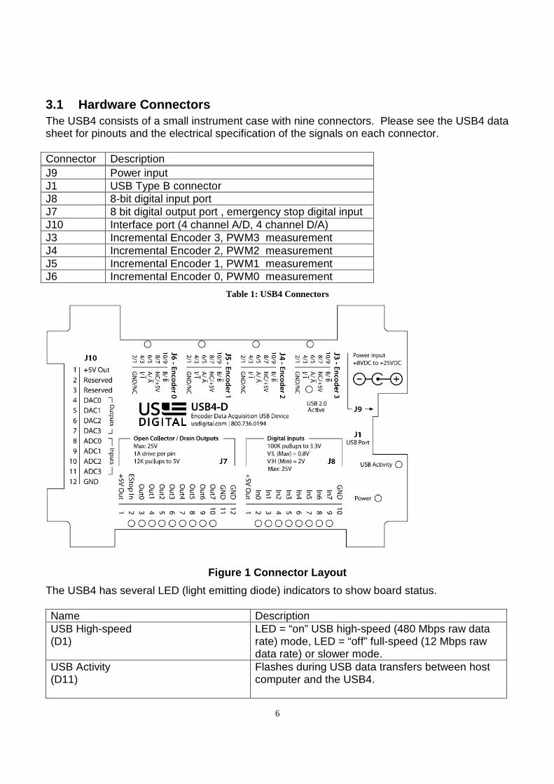
3.1 Hardware Connectors The USB4 consists of a small instrument case with nine connectors. Please see the USB4 data sheet for pinouts and the electrical specification of the signals on each connector. Connector Description J9 Power input J1 USB Type B connector J8 8-bit digital input port J7 8 bit digital output port , emergency stop digital input J10 Interface port (4 channel A/D, 4 channel D/A) J3 Incremental Encoder 3, PWM3 measurement J4 Incremental Encoder 2, PWM2 measurement J5 Incremental Encoder 1, PWM1 measurement J6 Incremental Encoder 0, PWM0 measurement
Table 1: USB4 Connectors
Figure 1 Connector Layout
The USB4 has several LED (light emitting diode) indicators to show board status. Name Description USB High-speed (D1)
LED = “on” USB high-speed (480 Mbps raw data rate) mode, LED = “off” full-speed (12 Mbps raw data rate) or slower mode.
USB Activity (D11)
Flashes during USB data transfers between host computer and the USB4.
7
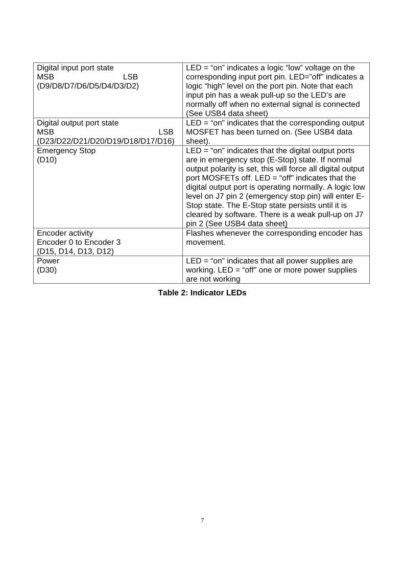
Digital input port state MSB LSB (D9/D8/D7/D6/D5/D4/D3/D2)
LED = “on” indicates a logic “low” voltage on the corresponding input port pin. LED=”off” indicates a logic “high” level on the port pin. Note that each input pin has a weak pull-up so the LED’s are normally off when no external signal is connected (See USB4 data sheet)
Digital output port state MSB LSB (D23/D22/D21/D20/D19/D18/D17/D16)
LED = “on” indicates that the corresponding output MOSFET has been turned on. (See USB4 data sheet).
Emergency Stop (D10)
LED = “on” indicates that the digital output ports are in emergency stop (E-Stop) state. If normal output polarity is set, this will force all digital output port MOSFETs off. LED = “off” indicates that the digital output port is operating normally. A logic low level on J7 pin 2 (emergency stop pin) will enter E-Stop state. The E-Stop state persists until it is cleared by software. There is a weak pull-up on J7 pin 2 (See USB4 data sheet)
Encoder activity Encoder 0 to Encoder 3 (D15, D14, D13, D12)
Flashes whenever the corresponding encoder has movement.
Power (D30)
LED = “on” indicates that all power supplies are working. LED = “off” one or more power supplies are not working
Table 2: Indicator LEDs
8
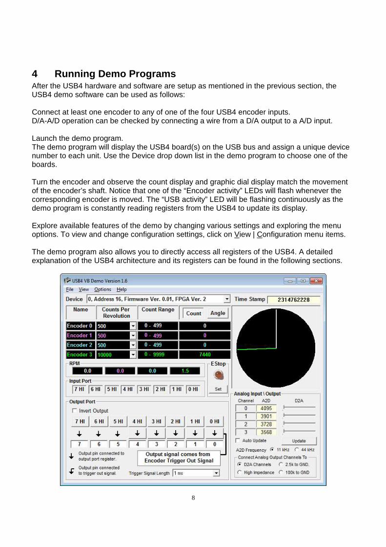
4 Running Demo Programs After the USB4 hardware and software are setup as mentioned in the previous section, the USB4 demo software can be used as follows: Connect at least one encoder to any of one of the four USB4 encoder inputs. D/A-A/D operation can be checked by connecting a wire from a D/A output to a A/D input. Launch the demo program. The demo program will display the USB4 board(s) on the USB bus and assign a unique device number to each unit. Use the Device drop down list in the demo program to choose one of the boards. Turn the encoder and observe the count display and graphic dial display match the movement of the encoder’s shaft. Notice that one of the “Encoder activity” LEDs will flash whenever the corresponding encoder is moved. The “USB activity” LED will be flashing continuously as the demo program is constantly reading registers from the USB4 to update its display. Explore available features of the demo by changing various settings and exploring the menu options. To view and change configuration settings, click on View | Configuration menu items. The demo program also allows you to directly access all registers of the USB4. A detailed explanation of the USB4 architecture and its registers can be found in the following sections.
9
5 Architecture of USB4
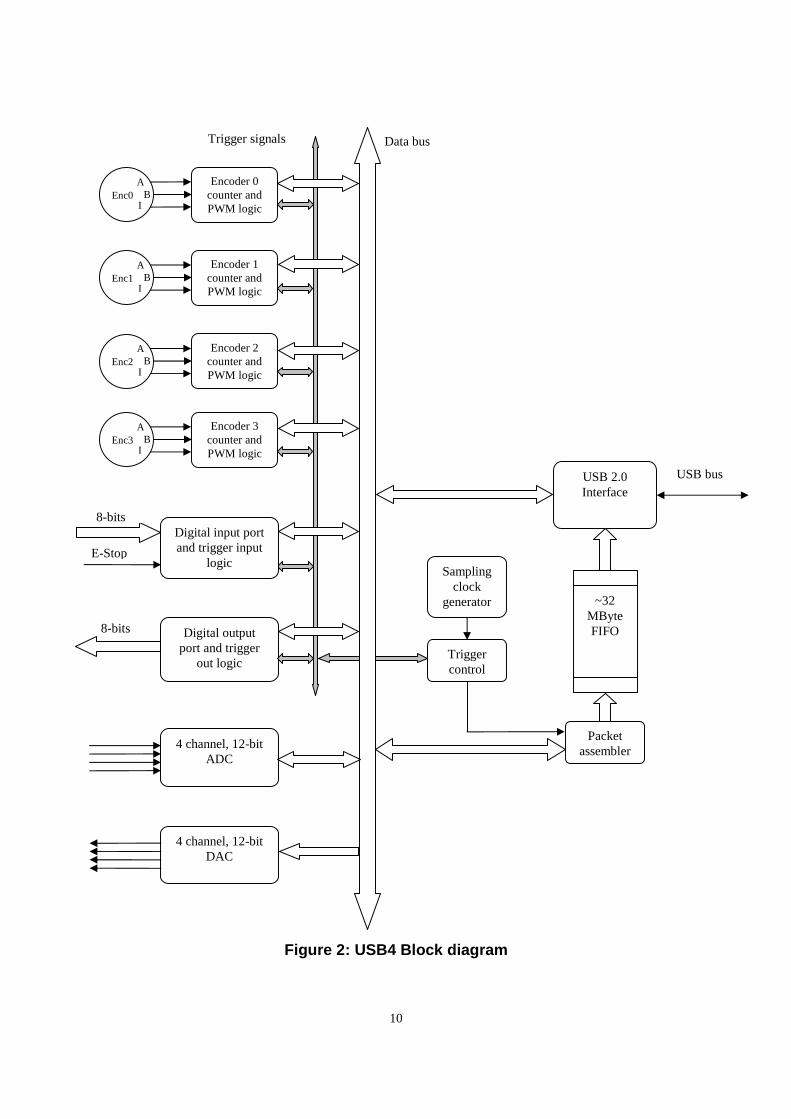
5.1 Overview See Figure 2: USB4 Block diagram. The USB4 is controlled by sixty-eight 32-bit registers. Registers are grouped as follows: 6.1.1 Incremental Encoder Registers 6.1.2 PWM Measurement Control Registers 6.1.4 Event Based Trigger - Input Port Simple External Trigger Registers 6.1.5 Time Based Trigger – Digital Input Port, ADC and PWM Trigger Registers 6.1.6 Time Based Trigger – Configuration Registers 6.1.7 FIFO Control/Status Registers 6.1.8 Digital Input/Output Port Registers 6.1.9 Analog Interface Registers
10
Figure 2: USB4 Block diagram
Encoder 0 counter and PWM logic
Enc0 A
B I
Digital output port and trigger
out logic
8-bits
4 channel, 12-bit ADC
4 channel, 12-bit DAC
USB 2.0 Interface
~32 MByte FIFO
USB bus
Packet assembler
Trigger control
Sampling clock
generator
Data bus Trigger signals
Encoder 1 counter and PWM logic
Enc1 A
B I
Encoder 2 counter and PWM logic
Enc2 A
B I
Encoder 3 counter and PWM logic
Enc3 A
B I
Digital input port and trigger input
logic
8-bits
E-Stop
11
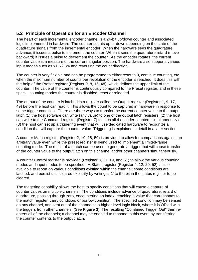
5.2 Principle of Operation for an Encoder Channel The heart of each incremental encoder channel is a 24-bit up/down counter and associated logic implemented in hardware. The counter counts up or down depending on the state of the quadrature signals from the incremental encoder. When the hardware sees the quadrature advance, it issues a pulse to increment the counter. When it sees the quadrature retard (move backward) it issues a pulse to decrement the counter. As the encoder rotates, the current counter value is a measure of the current angular position. The hardware also supports various input modes such as x1, x2, x4 and reversing the count direction. The counter is very flexible and can be programmed to either reset to 0, continue counting, etc. when the maximum number of counts per revolution of the encoder is reached. It does this with the help of the Preset register (Register 0, 8, 16, 48), which defines the upper limit of the counter. The value of the counter is continuously compared to the Preset register, and in these special counting modes the counter is disabled, reset or reloaded. The output of the counter is latched in a register called the Output register (Register 1, 9, 17, 49) before the host can read it. This allows the count to be captured in hardware in response to some trigger condition. There are three ways to transfer the current counter value to the output latch (1) the host software can write (any value) to one of the output latch registers, (2) the host can write to the Command register (Register 7) to latch all 4 encoder counters simultaneously or (3) the host can set up a triggering event that will use dedicated hardware to recognize a condition that will capture the counter value. Triggering is explained in detail in a later section. A counter Match register (Register 2, 10, 18, 50) is provided to allow for comparisons against an arbitrary value even while the preset register is being used to implement a limited-range counting mode. The result of a match can be used to generate a trigger that will cause transfer of the counter value to the output latch on this channel and/or other channels simultaneously. A counter Control register is provided (Register 3, 11, 19, and 51) to allow the various counting modes and input modes to be specified. A Status register (Register 4, 12, 20, 52) is also available to report on various conditions existing within the channel; some conditions are latched, and persist until cleared explicitly by writing a ‘1’ to the bit in the status register to be cleared. The triggering capability allows the host to specify conditions that will cause a capture of counter values on multiple channels. The conditions include advance of quadrature, retard of quadrature, passing through zero, encountering an index, reaching a value that corresponds to the match register, carry condition, or borrow condition. The specified condition may be sensed on any channel, and sent out of the channel to a higher level logic block, where it is OR'ed with the triggers from other channels. (See Figure 3 ) The resulting "Combined Trigger Out" then re-enters all of the channels; a channel may be enabled to respond to this event by transferring the counter contents to the output latch.
12
5.3 Single-Threaded vs multi-Threaded Programming The USB4.dll has been designed to provide user access to USB4 registers using a synchronized single threaded approach. Consequently, all calls to the USB4.dll must be made from the same thread. If you need to access the USB4.dll from multiple threads, a wrapper that manages synchronization must be written for each function.
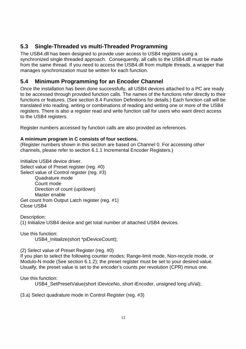
5.4 Minimum Programming for an Encoder Channel Once the installation has been done successfully, all USB4 devices attached to a PC are ready to be accessed through provided function calls. The names of the functions refer directly to their functions or features. (See section 8.4 Function Definitions for details.) Each function call will be translated into reading, writing or combinations of reading and writing one or more of the USB4 registers. There is also a register read and write function call for users who want direct access to the USB4 registers. Register numbers accessed by function calls are also provided as references. A minimum program in C consists of four sections. (Register numbers shown in this section are based on Channel 0. For accessing other channels, please refer to section 6.1.1 Incremental Encoder Registers.) Initialize USB4 device driver. Select value of Preset register (reg. #0) Select value of Control register (reg. #3)
Quadrature mode Count mode Direction of count (up/down) Master enable
Get count from Output Latch register (reg. #1) Close USB4 Description: (1) Initialize USB4 device and get total number of attached USB4 devices. Use this function:
USB4_Initialize(short *piDeviceCount); (2) Select value of Preset Register (reg. #0) If you plan to select the following counter modes; Range-limit mode, Non-recycle mode, or Modulo-N mode (See section 6.1.2); the preset register must be set to your desired value. Usually, the preset value is set to the encoder’s counts per revolution (CPR) minus one. Use this function:
USB4_SetPresetValue(short iDeviceNo, short iEncoder, unsigned long ulVal); (3.a) Select quadrature mode in Control Register (reg. #3)
13
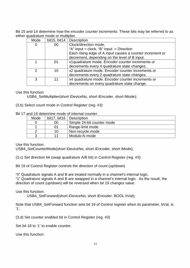
Bit 15 and 14 determine how the encoder counter increments: These bits may be referred to as either quadrature mode or multiplier.
Mode bit15, bit14 Description 0 00 Clock/direction mode.
“A” input = clock, “B” input = Direction Each rising edge of A input causes a counter increment or decrement, depending on the level of B input.
1 01 x1quadrature mode. Encoder counter increments or decrements every 4 quadrature state changes.
2 10 x2 quadrature mode. Encoder counter increments or decrements every 2 quadrature state changes.
3 11 x4 quadrature mode. Encoder counter increments or decrements on every quadrature state change.
Use this function:
USB4_SetMultiplier(short iDeviceNo, short iEncoder, short iMode); (3.b) Select count mode in Control Register (reg. #3) Bit 17 and 16 determine mode of internal counter.
Mode bit17, bit16 Description 0 00 Simple 24-bit counter mode 1 01 Range-limit mode 2 10 Non-recycle mode 3 11 Modulo-N mode
Use this function: USB4_SetCounterMode(short iDeviceNo, short iEncoder, short iMode); (3.c) Set direction bit (swap quadrature A/B bit) in Control Register (reg. #3) Bit 19 of Control Register controls the direction of count (up/down) “0” Quadrature signals A and B are treated normally in a channel’s internal logic. “1” Quadrature signals A and B are swapped in a channel’s internal logic. As the result, the direction of count (up/down) will be reversed when bit 19 changes value. Use this function:
USB4_SetForward(short iDeviceNo, short iEncoder, BOOL bVal); Note that USB4_SetForward function sets bit 19 of Control register when its parameter, bVal, is ‘1’. (3.d) Set counter enabled bit in Control Register (reg. #3) Set bit 18 to ‘1’ to enable counter. Use this function:
14
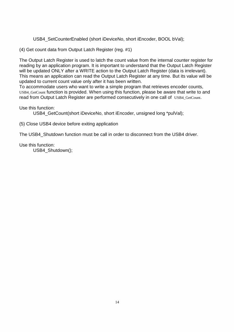
USB4_SetCounterEnabled (short iDeviceNo, short iEncoder, BOOL bVal);
(4) Get count data from Output Latch Register (reg. #1) The Output Latch Register is used to latch the count value from the internal counter register for reading by an application program. It is important to understand that the Output Latch Register will be updated ONLY after a WRITE action to the Output Latch Register (data is irrelevant). This means an application can read the Output Latch Register at any time. But its value will be updated to current count value only after it has been written. To accommodate users who want to write a simple program that retrieves encoder counts, USB4_GetCount function is provided. When using this function, please be aware that write to and read from Output Latch Register are performed consecutively in one call of USB4_GetCount. Use this function:
USB4_GetCount(short iDeviceNo, short iEncoder, unsigned long *pulVal);
(5) Close USB4 device before exiting application The USB4_Shutdown function must be call in order to disconnect from the USB4 driver. Use this function:
USB4_Shutdown();
15
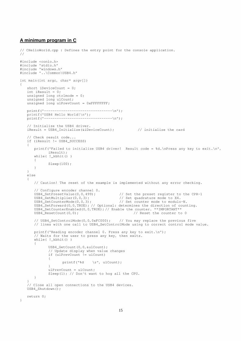
A minimum program in C // CHelloWorld.cpp : Defines the entry point for th e console application. // #include <conio.h> #include "stdio.h" #include "windows.h" #include "..\Common\USB4.h" int main(int argc, char* argv[]) short iDeviceCount = 0; int iResult = 0; unsigned long ctrlmode = 0; unsigned long ulCount; unsigned long ulPrevCount = 0xFFFFFFFF; printf("--------------------------------\n"); printf("USB4 Hello World!\n"); printf("--------------------------------\n"); // Initialize the USB4 driver. iResult = USB4_Initialize(&iDeviceCount); // in itialize the card // Check result code... if (iResult != USB4_SUCCESS) printf("Failed to initialize USB4 driver! Result code = %d.\nPress any key to exit.\n", iResult); while( !_kbhit() ) Sleep(100); else // Caution! The reset of the example is implement ed without any error checking. // Configure encoder channel 0. USB4_SetPresetValue(0,0,499); // Set the preset register to the CPR-1 USB4_SetMultiplier(0,0,3); // Set quadrature mo de to X4. USB4_SetCounterMode(0,0,3); // Set counter mode to modulo-N. USB4_SetForward(0,0,TRUE); // Optional: determine s the direction of counting. USB4_SetCounterEnabled(0,0,TRUE); // Enable the c ounter. **IMPORTANT** USB4_ResetCount(0,0); // Reset the counter to 0 // USB4_SetControlMode(0,0,0xFC000); // You may r eplace the previous five // lines with one call to USB4_SetControlMode usi ng to correct control mode value. printf("Reading encoder channel 0. Press any key to exit.\n"); // Waits for the user to press any key, then exit s. while( !_kbhit() ) USB4_GetCount(0,0,&ulCount); // Update display when value changes if (ulPrevCount != ulCount) printf("%d \r", ulCount); ulPrevCount = ulCount; Sleep(1); // Don't want to hog all the CPU. // Close all open connections to the USB4 devices. USB4_Shutdown(); return 0;
16
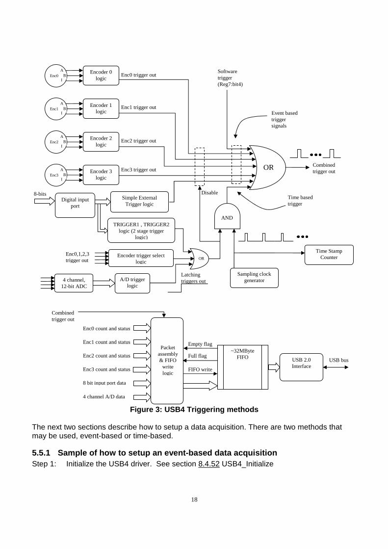
5.5 Triggering Methods Figure 3 shows a block diagram of the USB4’s triggering logic. The triggering logic is typically used to start continuous data capture or to capture events to the FIFO. It is possible to set up the streaming to start without any external trigger, so data can be captured from a software command. There are two types of trigger signals: (1) Event based triggers and (2) Time based triggers. All trigger source outputs are logically OR-ed together to form the “Combined Trigger Out” signal. Every time a “Combined Trigger Out” trigger pulse occurs, the USB4 will read the current time stamp counter value, 4 encoder counts and status, the 8 bit digital input port, and the 4 A/D channels. This data is assembled into a 40 byte packet and clocked into the FIFO. The FIFO is large enough to store 800k packets. The large FIFO buffer ensures that no data is lost if the PC is too busy to read the USB data in time. For lower speed applications, triggering and reading from the FIFO is not necessary. The PC can simply read the current encoder counts, ADC values, etc. directly from USB4 registers. “Event based” triggers can be from the 4 encoders or from the 8-bit digital input port. Encoder “events” are conditions such as the counter passing through zero, the count equaling the Match register, etc. See 6.1.1 Incremental Encoder Registers – Control register on how to enable triggering on these events. Note that in the Encoder’s Control register, bit23 allows the “Combined Trigger Out” signal to be used to latch the count of any one of the Encoder channels. This is useful to allow an event generated by one encoder channel to latch the count of another encoder channel or to automatically latch the encoder counters during triggering so software does not need to manually latch the count during USB streaming. Digital input port events occur on rising or falling edges of various bits on the input port. See Section 6.1.4 Event Based Trigger - Input Port Simple External Trigger Registers for the bit settings for input port triggering. Note that there is no periodic sampling clock in “Event based” triggering, a 40-byte data packet is generated and stored to the FIFO each time any of the enabled events occurs. For example, with event based triggering, we can configure the USB4 to capture a packet whenever input port bit 0 has a rising edge. In “Time based triggering” a trigger event on the encoders, digital input port, A/D channels or PWM channels is used to latch the enable of a periodic sample clock so the USB4 captures data at a constant sampling period. The sample clock is programmable for sample periods ranging from 2 µsec to approximately 2.39 hours. At 2 µsec per sample, the FIFO buffer would be filled in approximately 1.6 seconds. At 2.39 hours per sample, the FIFO buffer would be filled in approximately 223 years. Note: from Figure 3: USB4 Triggering methods , there are four possible ways to start a time-based data acquisition.
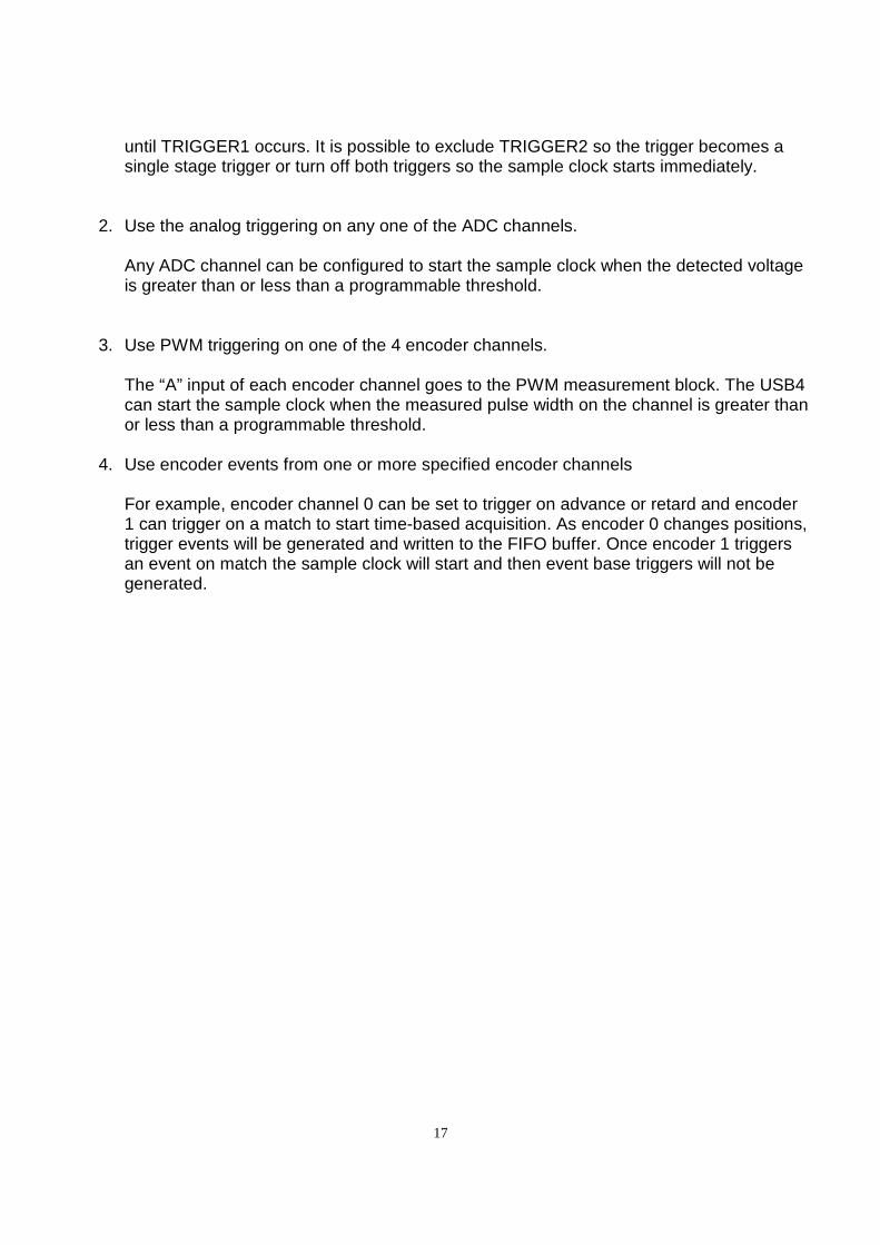
1. Use a two stage trigger on the digital input port.
The two trigger stages are called TRIGGER1 and TRIGGER2. The sample clock will start only if TRIGGER1 occurs first, then TRIGGER2. The TRIGGER2 event is not checked
17
until TRIGGER1 occurs. It is possible to exclude TRIGGER2 so the trigger becomes a single stage trigger or turn off both triggers so the sample clock starts immediately.
2. Use the analog triggering on any one of the ADC channels.
Any ADC channel can be configured to start the sample clock when the detected voltage is greater than or less than a programmable threshold.
3. Use PWM triggering on one of the 4 encoder channels. The “A” input of each encoder channel goes to the PWM measurement block. The USB4 can start the sample clock when the measured pulse width on the channel is greater than or less than a programmable threshold.
4. Use encoder events from one or more specified encoder channels
For example, encoder channel 0 can be set to trigger on advance or retard and encoder 1 can trigger on a match to start time-based acquisition. As encoder 0 changes positions, trigger events will be generated and written to the FIFO buffer. Once encoder 1 triggers an event on match the sample clock will start and then event base triggers will not be generated.
18
Figure 3: USB4 Triggering methods
The next two sections describe how to setup a data acquisition. There are two methods that may be used, event-based or time-based.
5.5.1 Sample of how to setup an event-based data ac quisition Step 1: Initialize the USB4 driver. See section 8.4.52 USB4_Initialize
Encoder 0 logic
Enc0 A
B I
Encoder 1 logic
Enc1 A
B I
Encoder 2 logic
Enc2 A
B I
Encoder 3 logic
Enc3 A
B I
OR
Simple External Trigger logic
Digital input port
8-bits
TRIGGER1 , TRIGGER2 logic (2 stage trigger
logic)
Enc0 trigger out
Enc1 trigger out
Enc2 trigger out
Enc3 trigger out
Sampling clock generator
Latching triggers out
Combined trigger out
USB 2.0 Interface
~32MByte FIFO USB bus
Enc0 count and status
Enc1 count and status
Enc2 count and status
Enc3 count and status
8 bit input port data
4 channel A/D data
Time Stamp Counter
Full flag
Empty flag Packet
assembly & FIFO
write logic
FIFO write
Combined trigger out
Software trigger (Reg7:bit4)
Event based trigger signals
Time based trigger
AND
4 channel, 12-bit ADC
OR
A/D trigger logic
Encoder trigger select logic
Enc0,1,2,3 trigger out
Disable
19
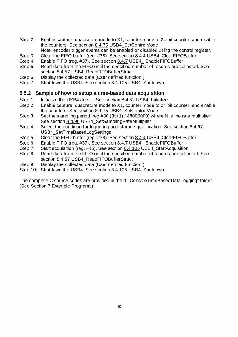
Step 2: Enable capture, quadrature mode to X1, counter mode to 24 bit counter, and enable the counters. See section 8.4.75 USB4_SetControlMode Note: encoder trigger events can be enabled or disabled using the control register.
Step 3: Clear the FIFO buffer (reg. #38). See section 8.4.4 USB4_ClearFIFOBuffer Step 4: Enable FIFO (reg. #37). See section 8.4.7 USB4_ EnableFIFOBuffer Step 5: Read data from the FIFO until the specified number of records are collected. See
section 8.4.57 USB4_ReadFIFOBufferStruct Step 6: Display the collected data (User defined function.) Step 7: Shutdown the USB4. See section 8.4.105 USB4_Shutdown
5.5.2 Sample of how to setup a time-based data acqu isition Step 1: Initialize the USB4 driver. See section 8.4.52 USB4_Initialize Step 2: Enable capture, quadrature mode to X1, counter mode to 24 bit counter, and enable
the counters. See section 8.4.75 USB4_SetControlMode Step 3: Set the sampling period. reg.#30 ((N+1) / 48000000) where N is the rate multiplier.
See section 8.4.96 USB4_SetSamplingRateMultiplier Step 4: Select the condition for triggering and storage qualification. See section 8.4.97
USB4_SetTimeBasedLogSettings Step 5: Clear the FIFO buffer (reg. #38). See section 8.4.4 USB4_ClearFIFOBuffer Step 6: Enable FIFO (reg. #37). See section 8.4.7 USB4_ EnableFIFOBuffer Step 7: Start acquisition (reg. #45). See section 8.4.106 USB4_StartAcquisition Step 8: Read data from the FIFO until the specified number of records are collected. See
section 8.4.57 USB4_ReadFIFOBufferStruct Step 9: Display the collected data (User defined function.) Step 10: Shutdown the USB4. See section 8.4.105 USB4_Shutdown The complete C source codes are provided in the “C ConsoleTimeBasedDataLogging” folder. (See Section 7 Example Programs)
20
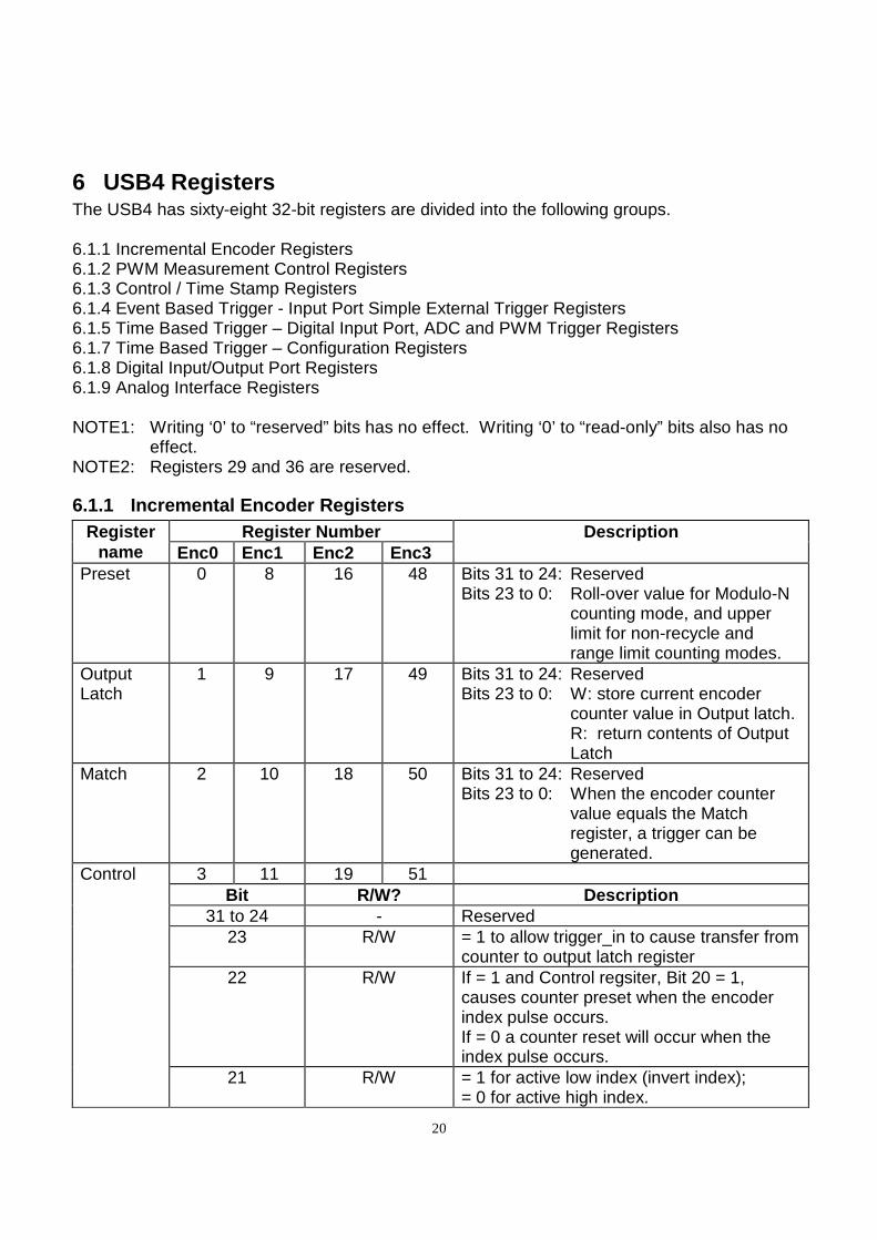
6 USB4 Registers The USB4 has sixty-eight 32-bit registers are divided into the following groups. 6.1.1 Incremental Encoder Registers 6.1.2 PWM Measurement Control Registers 6.1.3 Control / Time Stamp Registers 6.1.4 Event Based Trigger - Input Port Simple External Trigger Registers 6.1.5 Time Based Trigger – Digital Input Port, ADC and PWM Trigger Registers 6.1.7 Time Based Trigger – Configuration Registers 6.1.8 Digital Input/Output Port Registers 6.1.9 Analog Interface Registers NOTE1: Writing ‘0’ to “reserved” bits has no effect. Writing ‘0’ to “read-only” bits also has no
effect. NOTE2: Registers 29 and 36 are reserved.
6.1.1 Incremental Encoder Registers Register
name Register Number Description
Enc0 Enc1 Enc2 Enc3 Preset 0 8 16 48 Bits 31 to 24: Reserved
Bits 23 to 0: Roll-over value for Modulo-N counting mode, and upper limit for non-recycle and range limit counting modes.
Output Latch
1 9 17 49 Bits 31 to 24: Reserved Bits 23 to 0: W: store current encoder
counter value in Output latch. R: return contents of Output
Latch
Match 2 10 18 50 Bits 31 to 24: Reserved Bits 23 to 0: When the encoder counter
value equals the Match register, a trigger can be generated.
Control 3 11 19 51
Bit R/W? Description 31 to 24 - Reserved
23 R/W = 1 to allow trigger_in to cause transfer from counter to output latch register
22 R/W If = 1 and Control regsiter, Bit 20 = 1, causes counter preset when the encoder index pulse occurs. If = 0 a counter reset will occur when the index pulse occurs.
21 R/W = 1 for active low index (invert index); = 0 for active high index.
21
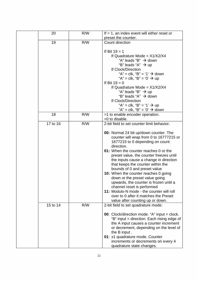
20 R/W If = 1, an index event will either reset or preset the counter.
19 R/W Count direction If Bit 19 = 1 If Quadrature Mode = X1/X2/X4 “A” leads “B” down “B” leads “A” up If Clock/Direction “A” = clk, “B” = ‘1’ down “A” = clk, “B” = ‘0’ up If Bit 19 = 0 If Quadrature Mode = X1/X2/X4 “A” leads “B” up “B” leads “A” down If Clock/Direction “A” = clk, “B” = ‘1’ up “A” = clk, “B” = ‘0’ down
18 R/W =1 to enable encoder operation. =0 to disable.
17 to 16 R/W 2-bit field to set counter limit behavior. 00: Normal 24 bit up/down counter. The
counter will wrap from 0 to 16777215 or 1677215 to 0 depending on count direction.
01: When the counter reaches 0 or the preset value, the counter freezes until the inputs cause a change in direction that keeps the counter within the bounds of 0 and preset value
10: When the counter reaches 0 going down or the preset value going upwards, the counter is frozen until a channel reset is performed
11: Modulo-N mode - the counter will roll over to 0 after it matches the Preset value after counting up or down.
15 to 14 R/W 2-bit field to set quadrature mode: 00: Clock/direction mode. “A” input = clock.
“B” input = direction. Each rising edge of the A input causes a counter increment or decrement, depending on the level of the B input .
01: x1 quadrature mode. Counter increments or decrements on every 4 quadrature state changes.
22
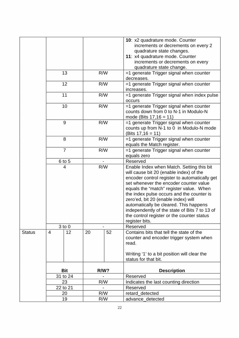
10: x2 quadrature mode. Counter increments or decrements on every 2 quadrature state changes.
11: x4 quadrature mode. Counter increments or decrements on every quadrature state change.
13 R/W =1 generate Trigger signal when counter decreases.
12 R/W =1 generate Trigger signal when counter increases.
11 R/W =1 generate Trigger signal when index pulse occurs
10 R/W =1 generate Trigger signal when counter counts down from 0 to N-1 in Modulo-N mode (Bits 17,16 = 11)
9 R/W =1 generate Trigger signal when counter counts up from N-1 to 0 in Modulo-N mode (Bits 17,16 = 11)
8 R/W =1 generate Trigger signal when counter equals the Match register.
7 R/W =1 generate Trigger signal when counter equals zero
6 to 5 - Reserved 4 R/W Enable Index when Match. Setting this bit
will cause bit 20 (enable index) of the encoder control register to automatically get set whenever the encoder counter value equals the “match” register value. When the index pulse occurs and the counter is zero’ed, bit 20 (enable index) will automatically be cleared. This happens independently of the state of Bits 7 to 13 of the control register or the counter status register bits.
3 to 0 - Reserved Status
4 12 20 52 Contains bits that tell the state of the counter and encoder trigger system when read. Writing ‘1’ to a bit position will clear the status for that bit.
Bit
R/W?
Description
31 to 24 - Reserved 23 R/W Indicates the last counting direction
22 to 21 - Reserved 20 R/W retard_detected 19 R/W advance_detected
23
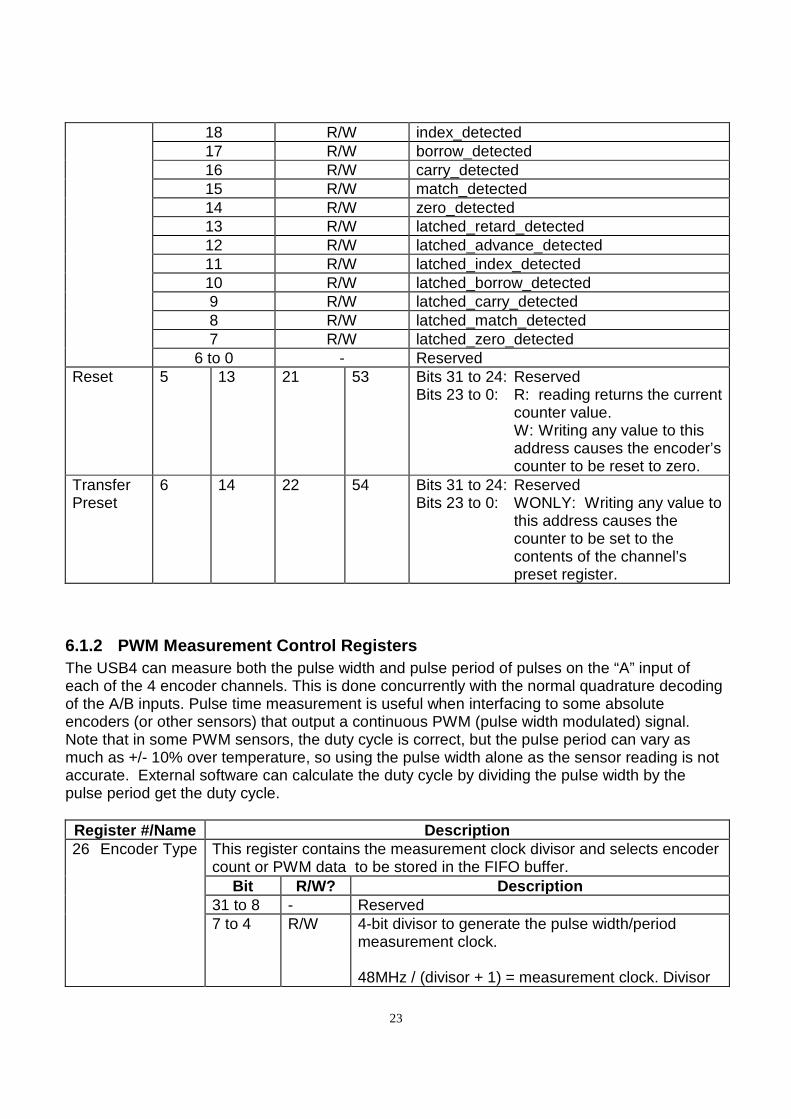
18 R/W index_detected 17 R/W borrow_detected 16 R/W carry_detected 15 R/W match_detected 14 R/W zero_detected 13 R/W latched_retard_detected 12 R/W latched_advance_detected 11 R/W latched_index_detected 10 R/W latched_borrow_detected 9 R/W latched_carry_detected 8 R/W latched_match_detected 7 R/W latched_zero_detected
6 to 0 - Reserved Reset 5 13 21 53 Bits 31 to 24: Reserved
Bits 23 to 0: R: reading returns the current counter value. W: Writing any value to this address causes the encoder’s counter to be reset to zero.
Transfer Preset
6 14 22 54 Bits 31 to 24: Reserved Bits 23 to 0: WONLY: Writing any value to
this address causes the counter to be set to the contents of the channel’s preset register.
6.1.2 PWM Measurement Control Registers The USB4 can measure both the pulse width and pulse period of pulses on the “A” input of each of the 4 encoder channels. This is done concurrently with the normal quadrature decoding of the A/B inputs. Pulse time measurement is useful when interfacing to some absolute encoders (or other sensors) that output a continuous PWM (pulse width modulated) signal. Note that in some PWM sensors, the duty cycle is correct, but the pulse period can vary as much as +/- 10% over temperature, so using the pulse width alone as the sensor reading is not accurate. External software can calculate the duty cycle by dividing the pulse width by the pulse period get the duty cycle.
Register #/Name Description 26 Encoder Type This register contains the measurement clock divisor and selects encoder
count or PWM data to be stored in the FIFO buffer. Bit R/W? Descript ion
31 to 8 - Reserved 7 to 4 R/W 4-bit divisor to generate the pulse width/period
measurement clock. 48MHz / (divisor + 1) = measurement clock. Divisor
24
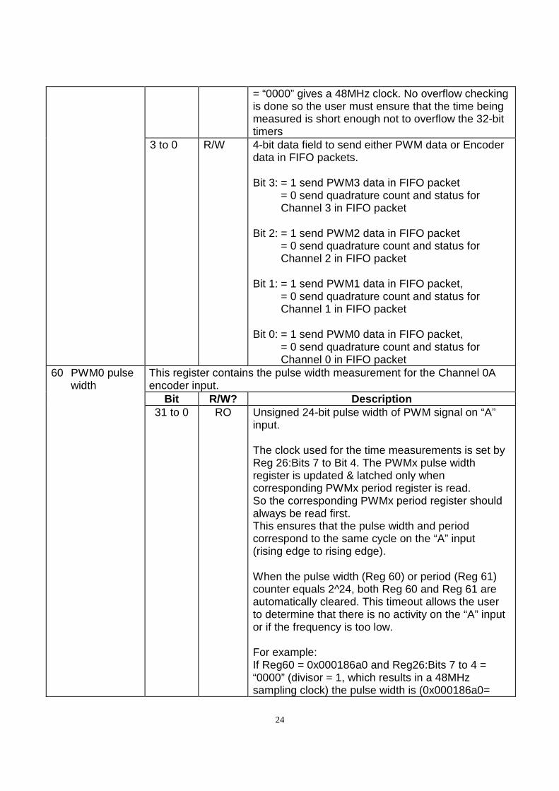
= “0000” gives a 48MHz clock. No overflow checking is done so the user must ensure that the time being measured is short enough not to overflow the 32-bit timers
3 to 0 R/W 4-bit data field to send either PWM data or Encoder data in FIFO packets. Bit 3: = 1 send PWM3 data in FIFO packet = 0 send quadrature count and status for
Channel 3 in FIFO packet Bit 2: = 1 send PWM2 data in FIFO packet = 0 send quadrature count and status for
Channel 2 in FIFO packet Bit 1: = 1 send PWM1 data in FIFO packet, = 0 send quadrature count and status for
Channel 1 in FIFO packet Bit 0: = 1 send PWM0 data in FIFO packet, = 0 send quadrature count and status for
Channel 0 in FIFO packet 60 PWM0 pulse
width This register contains the pulse width measurement for the Channel 0A encoder input.
Bit R/W? Description 31 to 0 RO Unsigned 24-bit pulse width of PWM signal on “A”
input. The clock used for the time measurements is set by Reg 26:Bits 7 to Bit 4. The PWMx pulse width register is updated & latched only when corresponding PWMx period register is read. So the corresponding PWMx period register should always be read first. This ensures that the pulse width and period correspond to the same cycle on the “A” input (rising edge to rising edge). When the pulse width (Reg 60) or period (Reg 61) counter equals 2^24, both Reg 60 and Reg 61 are automatically cleared. This timeout allows the user to determine that there is no activity on the “A” input or if the frequency is too low. For example: If Reg60 = 0x000186a0 and Reg26:Bits 7 to 4 = “0000” (divisor = 1, which results in a 48MHz sampling clock) the pulse width is (0x000186a0=
25
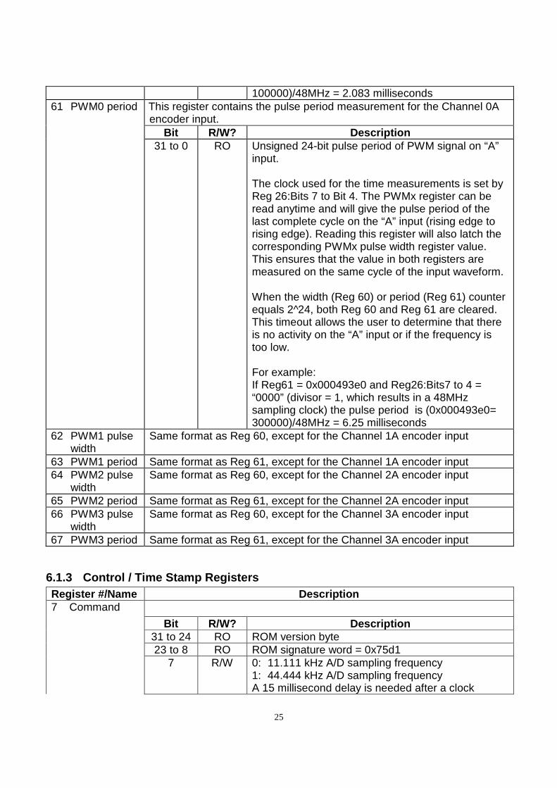
100000)/48MHz = 2.083 milliseconds 61 PWM0 period This register contains the pulse period measurement for the Channel 0A
encoder input. Bit R/W? Description
31 to 0 RO Unsigned 24-bit pulse period of PWM signal on “A” input. The clock used for the time measurements is set by Reg 26:Bits 7 to Bit 4. The PWMx register can be read anytime and will give the pulse period of the last complete cycle on the “A” input (rising edge to rising edge). Reading this register will also latch the corresponding PWMx pulse width register value. This ensures that the value in both registers are measured on the same cycle of the input waveform. When the width (Reg 60) or period (Reg 61) counter equals 2^24, both Reg 60 and Reg 61 are cleared. This timeout allows the user to determine that there is no activity on the “A” input or if the frequency is too low. For example: If Reg61 = 0x000493e0 and Reg26:Bits7 to 4 = “0000” (divisor = 1, which results in a 48MHz sampling clock) the pulse period is (0x000493e0= 300000)/48MHz = 6.25 milliseconds
62 PWM1 pulse width
Same format as Reg 60, except for the Channel 1A encoder input
63 PWM1 period Same format as Reg 61, except for the Channel 1A encoder input 64 PWM2 pulse
width Same format as Reg 60, except for the Channel 2A encoder input
65 PWM2 period Same format as Reg 61, except for the Channel 2A encoder input 66 PWM3 pulse
width Same format as Reg 60, except for the Channel 3A encoder input
67 PWM3 period Same format as Reg 61, except for the Channel 3A encoder input
6.1.3 Control / Time Stamp Registers Register #/Name Description 7 Command
Bit R/W? Description 31 to 24 RO ROM version byte 23 to 8 RO ROM signature word = 0x75d1
7 R/W 0: 11.111 kHz A/D sampling frequency 1: 44.444 kHz A/D sampling frequency A 15 millisecond delay is needed after a clock
26
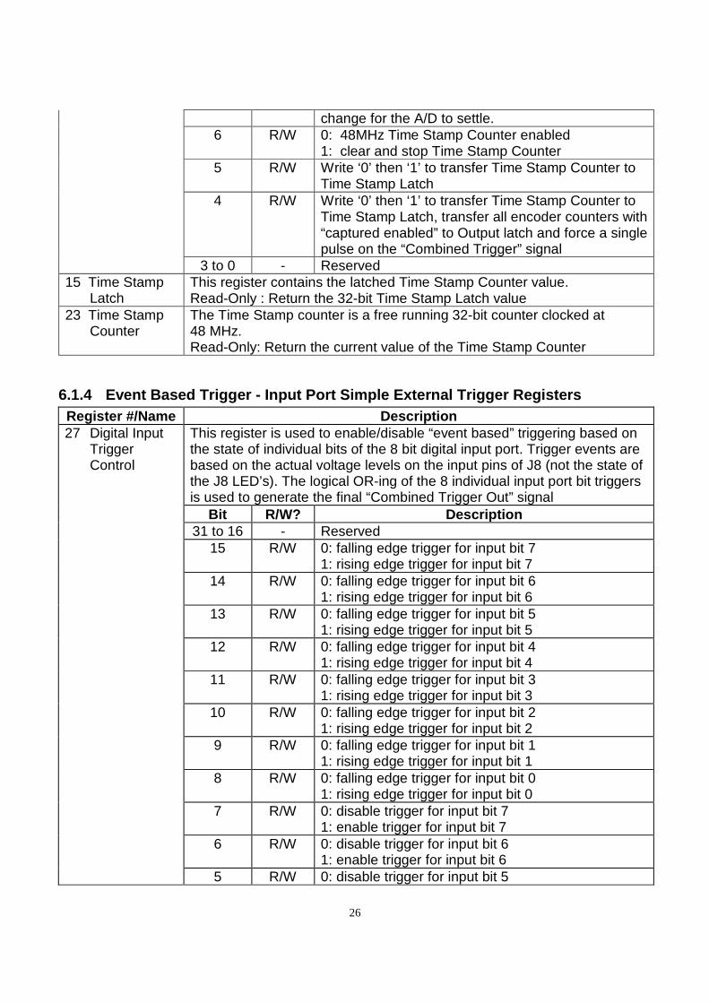
change for the A/D to settle. 6 R/W 0: 48MHz Time Stamp Counter enabled
1: clear and stop Time Stamp Counter
5 R/W Write ‘0’ then ‘1’ to transfer Time Stamp Counter to Time Stamp Latch
4 R/W Write ‘0’ then ‘1’ to transfer Time Stamp Counter to Time Stamp Latch, transfer all encoder counters with “captured enabled” to Output latch and force a single pulse on the “Combined Trigger” signal
3 to 0 - Reserved 15 Time Stamp
Latch This register contains the latched Time Stamp Counter value. Read-Only : Return the 32-bit Time Stamp Latch value
23 Time Stamp Counter
The Time Stamp counter is a free running 32-bit counter clocked at 48 MHz. Read-Only: Return the current value of the Time Stamp Counter
6.1.4 Event Based Trigger - Input Port Simple Exter nal Trigger Registers Register #/Name Description 27 Digital Input
Trigger Control
This register is used to enable/disable “event based” triggering based on the state of individual bits of the 8 bit digital input port. Trigger events are based on the actual voltage levels on the input pins of J8 (not the state of the J8 LED’s). The logical OR-ing of the 8 individual input port bit triggers is used to generate the final “Combined Trigger Out” signal
Bit R/W? Description 31 to 16 - Reserved
15 R/W 0: falling edge trigger for input bit 7 1: rising edge trigger for input bit 7
14 R/W 0: falling edge trigger for input bit 6 1: rising edge trigger for input bit 6
13 R/W 0: falling edge trigger for input bit 5 1: rising edge trigger for input bit 5
12 R/W 0: falling edge trigger for input bit 4 1: rising edge trigger for input bit 4
11 R/W 0: falling edge trigger for input bit 3 1: rising edge trigger for input bit 3
10 R/W 0: falling edge trigger for input bit 2 1: rising edge trigger for input bit 2
9 R/W 0: falling edge trigger for input bit 1 1: rising edge trigger for input bit 1
8 R/W 0: falling edge trigger for input bit 0 1: rising edge trigger for input bit 0
7 R/W 0: disable trigger for input bit 7 1: enable trigger for input bit 7
6 R/W 0: disable trigger for input bit 6 1: enable trigger for input bit 6
5 R/W 0: disable trigger for input bit 5
27
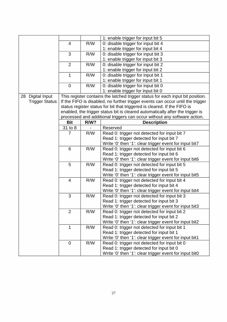
1: enable trigger for input bit 5
4 R/W 0: disable trigger for input bit 4 1: enable trigger for input bit 4
3 R/W 0: disable trigger for input bit 3 1: enable trigger for input bit 3
2 R/W 0: disable trigger for input bit 2 1: enable trigger for input bit 2
1 R/W 0: disable trigger for input bit 1 1: enable trigger for input bit 1
0 R/W 0: disable trigger for input bit 0 1: enable trigger for input bit 0
28 Digital Input Trigger Status
This register contains the latched trigger status for each input bit position. If the FIFO is disabled, no further trigger events can occur until the trigger status register status for bit that triggered is cleared. If the FIFO is enabled, the trigger status bit is cleared automatically after the trigger is processed and additional triggers can occur without any software action.
Bit R/W? Description 31 to 8 - Reserved
7 R/W Read 0: trigger not detected for input bit 7 Read 1: trigger detected for input bit 7 Write ‘0’ then ‘1’: clear trigger event for input bit7
6 R/W Read 0: trigger not detected for input bit 6 Read 1: trigger detected for input bit 6 Write ‘0’ then ‘1’: clear trigger event for input bit6
5 R/W Read 0: trigger not detected for input bit 5 Read 1: trigger detected for input bit 5 Write ‘0’ then ‘1’: clear trigger event for input bit5
4 R/W Read 0: trigger not detected for input bit 4 Read 1: trigger detected for input bit 4 Write ‘0’ then ‘1’: clear trigger event for input bit4
3 R/W Read 0: trigger not detected for input bit 3 Read 1: trigger detected for input bit 3 Write ‘0’ then ‘1’: clear trigger event for input bit3
2 R/W Read 0: trigger not detected for input bit 2 Read 1: trigger detected for input bit 2 Write ‘0’ then ‘1’: clear trigger event for input bit2
1 R/W Read 0: trigger not detected for input bit 1 Read 1: trigger detected for input bit 1 Write ‘0’ then ‘1’: clear trigger event for input bit1
0 R/W Read 0: trigger not detected for input bit 0 Read 1: trigger detected for input bit 0 Write ‘0’ then ‘1’: clear trigger event for input bit0
28
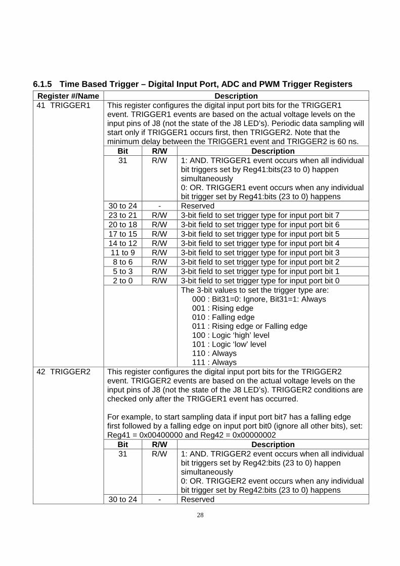
6.1.5 Time Based Trigger – Digital Input Port, ADC and PWM Trigger Registers Register #/Name Description 41 TRIGGER1 This register configures the digital input port bits for the TRIGGER1
event. TRIGGER1 events are based on the actual voltage levels on the input pins of J8 (not the state of the J8 LED’s). Periodic data sampling will start only if TRIGGER1 occurs first, then TRIGGER2. Note that the minimum delay between the TRIGGER1 event and TRIGGER2 is 60 ns.
Bit R/W Description 31 R/W 1: AND. TRIGGER1 event occurs when all individual
bit triggers set by Reg41:bits(23 to 0) happen simultaneously 0: OR. TRIGGER1 event occurs when any individual bit trigger set by Reg41:bits (23 to 0) happens
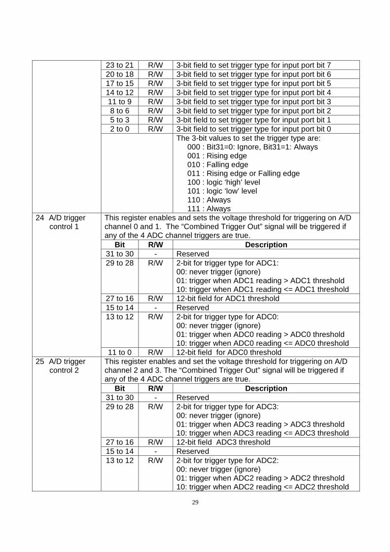
30 to 24 - Reserved 23 to 21 R/W 3-bit field to set trigger type for input port bit 7 20 to 18 R/W 3-bit field to set trigger type for input port bit 6 17 to 15 R/W 3-bit field to set trigger type for input port bit 5 14 to 12 R/W 3-bit field to set trigger type for input port bit 4 11 to 9 R/W 3-bit field to set trigger type for input port bit 3 8 to 6 R/W 3-bit field to set trigger type for input port bit 2 5 to 3 R/W 3-bit field to set trigger type for input port bit 1 2 to 0 R/W 3-bit field to set trigger type for input port bit 0
The 3-bit values to set the trigger type are: 000 : Bit31=0: Ignore, Bit31=1: Always 001 : Rising edge 010 : Falling edge 011 : Rising edge or Falling edge 100 : Logic ‘high’ level 101 : Logic ‘low’ level 110 : Always 111 : Always
42 TRIGGER2 This register configures the digital input port bits for the TRIGGER2 event. TRIGGER2 events are based on the actual voltage levels on the input pins of J8 (not the state of the J8 LED’s). TRIGGER2 conditions are checked only after the TRIGGER1 event has occurred. For example, to start sampling data if input port bit7 has a falling edge first followed by a falling edge on input port bit0 (ignore all other bits), set: Reg41 = 0x00400000 and Reg42 = 0x00000002
Bit R/W Description 31 R/W 1: AND. TRIGGER2 event occurs when all individual
bit triggers set by Reg42:bits (23 to 0) happen simultaneously 0: OR. TRIGGER2 event occurs when any individual bit trigger set by Reg42:bits (23 to 0) happens
30 to 24 - Reserved
29
23 to 21 R/W 3-bit field to set trigger type for input port bit 7 20 to 18 R/W 3-bit field to set trigger type for input port bit 6 17 to 15 R/W 3-bit field to set trigger type for input port bit 5 14 to 12 R/W 3-bit field to set trigger type for input port bit 4 11 to 9 R/W 3-bit field to set trigger type for input port bit 3 8 to 6 R/W 3-bit field to set trigger type for input port bit 2 5 to 3 R/W 3-bit field to set trigger type for input port bit 1 2 to 0 R/W 3-bit field to set trigger type for input port bit 0
The 3-bit values to set the trigger type are: 000 : Bit31=0: Ignore, Bit31=1: Always 001 : Rising edge 010 : Falling edge 011 : Rising edge or Falling edge 100 : logic ‘high’ level 101 : logic ‘low’ level 110 : Always 111 : Always
24 A/D trigger control 1
This register enables and sets the voltage threshold for triggering on A/D channel 0 and 1. The “Combined Trigger Out” signal will be triggered if any of the 4 ADC channel triggers are true.
Bit R/W Description 31 to 30 - Reserved 29 to 28 R/W 2-bit for trigger type for ADC1:
00: never trigger (ignore) 01: trigger when ADC1 reading > ADC1 threshold 10: trigger when ADC1 reading <= ADC1 threshold
27 to 16 R/W 12-bit field for ADC1 threshold 15 to 14 - Reserved 13 to 12 R/W 2-bit for trigger type for ADC0:
00: never trigger (ignore) 01: trigger when ADC0 reading > ADC0 threshold 10: trigger when ADC0 reading <= ADC0 threshold
11 to 0 R/W 12-bit field for ADC0 threshold 25 A/D trigger
control 2 This register enables and set the voltage threshold for triggering on A/D channel 2 and 3. The “Combined Trigger Out” signal will be triggered if any of the 4 ADC channel triggers are true.
Bit R/W Description 31 to 30 - Reserved 29 to 28 R/W 2-bit for trigger type for ADC3:
00: never trigger (ignore) 01: trigger when ADC3 reading > ADC3 threshold 10: trigger when ADC3 reading <= ADC3 threshold
27 to 16 R/W 12-bit field ADC3 threshold 15 to 14 - Reserved 13 to 12 R/W 2-bit for trigger type for ADC2:
00: never trigger (ignore) 01: trigger when ADC2 reading > ADC2 threshold 10: trigger when ADC2 reading <= ADC2 threshold
30
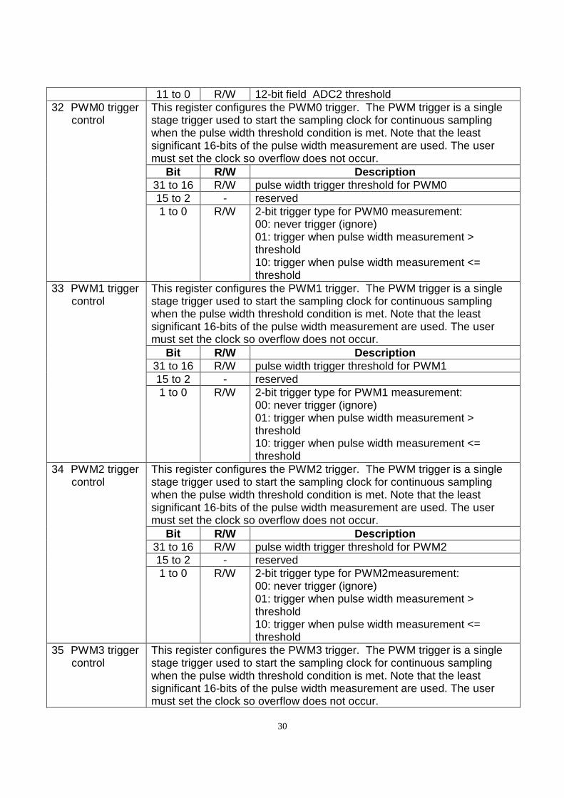
11 to 0 R/W 12-bit field ADC2 threshold 32 PWM0 trigger
control This register configures the PWM0 trigger. The PWM trigger is a single stage trigger used to start the sampling clock for continuous sampling when the pulse width threshold condition is met. Note that the least significant 16-bits of the pulse width measurement are used. The user must set the clock so overflow does not occur.
Bit R/W Description 31 to 16 R/W pulse width trigger threshold for PWM0 15 to 2 - reserved 1 to 0 R/W 2-bit trigger type for PWM0 measurement:
00: never trigger (ignore) 01: trigger when pulse width measurement > threshold 10: trigger when pulse width measurement <= threshold
33 PWM1 trigger control
This register configures the PWM1 trigger. The PWM trigger is a single stage trigger used to start the sampling clock for continuous sampling when the pulse width threshold condition is met. Note that the least significant 16-bits of the pulse width measurement are used. The user must set the clock so overflow does not occur.
Bit R/W Description 31 to 16 R/W pulse width trigger threshold for PWM1 15 to 2 - reserved 1 to 0 R/W 2-bit trigger type for PWM1 measurement:
00: never trigger (ignore) 01: trigger when pulse width measurement > threshold 10: trigger when pulse width measurement <= threshold
34 PWM2 trigger control
This register configures the PWM2 trigger. The PWM trigger is a single stage trigger used to start the sampling clock for continuous sampling when the pulse width threshold condition is met. Note that the least significant 16-bits of the pulse width measurement are used. The user must set the clock so overflow does not occur.
Bit R/W Description 31 to 16 R/W pulse width trigger threshold for PWM2 15 to 2 - reserved 1 to 0 R/W 2-bit trigger type for PWM2measurement:
00: never trigger (ignore) 01: trigger when pulse width measurement > threshold 10: trigger when pulse width measurement <= threshold
35 PWM3 trigger control
This register configures the PWM3 trigger. The PWM trigger is a single stage trigger used to start the sampling clock for continuous sampling when the pulse width threshold condition is met. Note that the least significant 16-bits of the pulse width measurement are used. The user must set the clock so overflow does not occur.
31
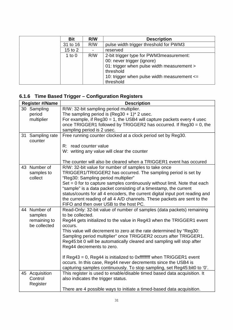
Bit R/W Description 31 to 16 R/W pulse width trigger threshold for PWM3 15 to 2 - reserved 1 to 0 R/W 2-bit trigger type for PWM3measurement:
00: never trigger (ignore) 01: trigger when pulse width measurement > threshold 10: trigger when pulse width measurement <= threshold
6.1.6 Time Based Trigger – Configuration Registers Register #/Name Description 30 Sampling
period multiplier
R/W: 32-bit sampling period multiplier. The sampling period is (Reg30 + 1)* 2 usec. For example, if Reg30 = 1, the USB4 will capture packets every 4 usec once TRIGGER1 followed by TRIGGER2 has occurred. If Reg30 = 0, the sampling period is 2 usec.
31 Sampling rate counter
Free running counter clocked at a clock period set by Reg30. R: read counter value W: writing any value will clear the counter The counter will also be cleared when a TRIGGER1 event has occured
43 Number of samples to collect
R/W: 32-bit value for number of samples to take once TRIGGER1/TRIGGER2 has occurred. The sampling period is set by “Reg30: Sampling period multiplier” Set = 0 for to capture samples continuously without limit. Note that each “sample” is a data packet consisting of a timestamp, the current status/counts for all 4 encoders, the current digital input port reading and the current reading of all 4 A/D channels. These packets are sent to the FIFO and then over USB to the host PC.
44 Number of samples remaining to be collected
Read-Only: 32-bit value of number of samples (data packets) remaining to be collected. Reg44 gets initialized to the value in Reg43 when the TRIGGER1 event occurs. This value will decrement to zero at the rate determined by “Reg30: Sampling period multiplier” once TRIGGER2 occurs after TRIGGER1. Reg45:bit 0 will be automatically cleared and sampling will stop after Reg44 decrements to zero. If Reg43 = 0, Reg44 is initialized to 0xffffffff when TRIGGER1 event occurs. In this case, Reg44 never decrements since the USB4 is capturing samples continuously. To stop sampling, set Reg45:bit0 to ‘0’.
45 Acquisition Control Register
This register is used to enable/disable timed based data acquisition. It also indicates the trigger status. There are 4 possible ways to initiate a timed-based data acquisition.
32
These 4 sources are OR-ed together to form the start signal: - Setup digital input TRIGGER1 (Reg41) and TRIGGER2 (Reg42). - Setup a ADC input trigger condition using reg24 and reg 25. - Setup a PWM pulse width trigger condition using registers 32,33,34,35 - Setup an encoder event using reg45 bits 4-7 (be sure to clear the encoder triggers in the Status register before setting Reg45:bit0 to ‘1’) See USB4_GetTimeBasedLogSettings(…) and USB4_SetTimeBasedLogSettings(…) functions Note: It is possible to initially setup event based logging and then have a specified encoder channel start time-based logging. Note: when the ADC,PWM or Encoder time based trigger event occurs, Reg45 bit1 and bit3 both get set since these events are single stage triggers and time based triggering starts as normal. If Reg45:bit3 is set and time based triggering has started, event based triggers are disabled until Reg45:bit3 is cleared by writing a ‘0’ to Reg45:bit0
Bit R/W Description 31 to 8 - Reserved
7 R/W = 0 Encoder channel 3 disabled from time-base trigger.
= 1 Encoder channel 3 events are enabled for time-base trigger.
6 R/W = 0 Encoder channel 2 disabled from time-base trigger.
= 1 Encoder channel 2 events are enabled for time-base trigger.
5 R/W = 0 Encoder channel 1 disabled from time-base trigger.
= 1 Encoder channel 1 events are enabled for time-base trigger.
4 R/W = 0 Encoder channel 0 disabled from time-base trigger.
= 1 Encoder channel 0 events are enabled for time-base trigger.
3 RO = 0 TRIGGER2 event not occurred = 1 TRIGGER2 event has occurred (this bit can only
be ‘1’ if TRIGGER1 has occurred first). 2 RO = 0 continuous mode not started
= 1 if (Reg45:bit3 = 1) and (Reg43 = 0). 1 RO = 0 TRIGGER1 event not occurred
= 1 TRIGGER1 event has occurred. 0 R/W = 0 disable timed based data acquisition and reset
TRIGGER1 & TRIGGER2. This will also clear Reg45:bits 1,2,3 and set Reg44 = 0.
= 1 enable time based data acquisition and waits for TRIGGER1 & TRIGGER2 occur.
33
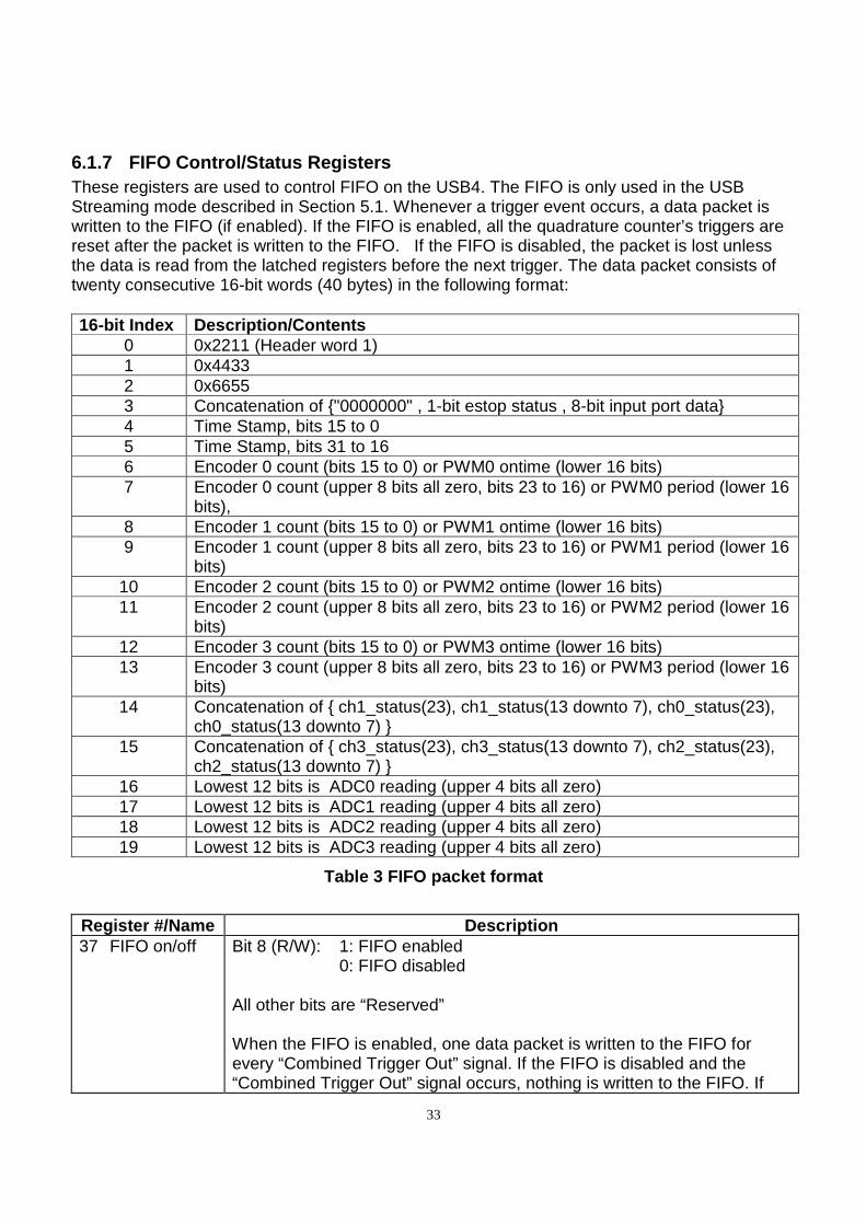
6.1.7 FIFO Control/Status Registers These registers are used to control FIFO on the USB4. The FIFO is only used in the USB Streaming mode described in Section 5.1. Whenever a trigger event occurs, a data packet is written to the FIFO (if enabled). If the FIFO is enabled, all the quadrature counter’s triggers are reset after the packet is written to the FIFO. If the FIFO is disabled, the packet is lost unless the data is read from the latched registers before the next trigger. The data packet consists of twenty consecutive 16-bit words (40 bytes) in the following format: 16-bit Index Description/Contents
0 0x2211 (Header word 1) 1 0x4433 2 0x6655 3 Concatenation of "0000000" , 1-bit estop status , 8-bit input port data 4 Time Stamp, bits 15 to 0 5 Time Stamp, bits 31 to 16 6 Encoder 0 count (bits 15 to 0) or PWM0 ontime (lower 16 bits) 7 Encoder 0 count (upper 8 bits all zero, bits 23 to 16) or PWM0 period (lower 16
bits), 8 Encoder 1 count (bits 15 to 0) or PWM1 ontime (lower 16 bits) 9 Encoder 1 count (upper 8 bits all zero, bits 23 to 16) or PWM1 period (lower 16
bits) 10 Encoder 2 count (bits 15 to 0) or PWM2 ontime (lower 16 bits) 11 Encoder 2 count (upper 8 bits all zero, bits 23 to 16) or PWM2 period (lower 16
bits) 12 Encoder 3 count (bits 15 to 0) or PWM3 ontime (lower 16 bits) 13 Encoder 3 count (upper 8 bits all zero, bits 23 to 16) or PWM3 period (lower 16
bits) 14 Concatenation of ch1_status(23), ch1_status(13 downto 7), ch0_status(23),
ch0_status(13 downto 7) 15 Concatenation of ch3_status(23), ch3_status(13 downto 7), ch2_status(23),
ch2_status(13 downto 7) 16 Lowest 12 bits is ADC0 reading (upper 4 bits all zero) 17 Lowest 12 bits is ADC1 reading (upper 4 bits all zero) 18 Lowest 12 bits is ADC2 reading (upper 4 bits all zero) 19 Lowest 12 bits is ADC3 reading (upper 4 bits all zero)
Table 3 FIFO packet format
Register #/Name Description 37 FIFO on/off Bit 8 (R/W): 1: FIFO enabled
0: FIFO disabled
All other bits are “Reserved”
When the FIFO is enabled, one data packet is written to the FIFO for every “Combined Trigger Out” signal. If the FIFO is disabled and the “Combined Trigger Out” signal occurs, nothing is written to the FIFO. If
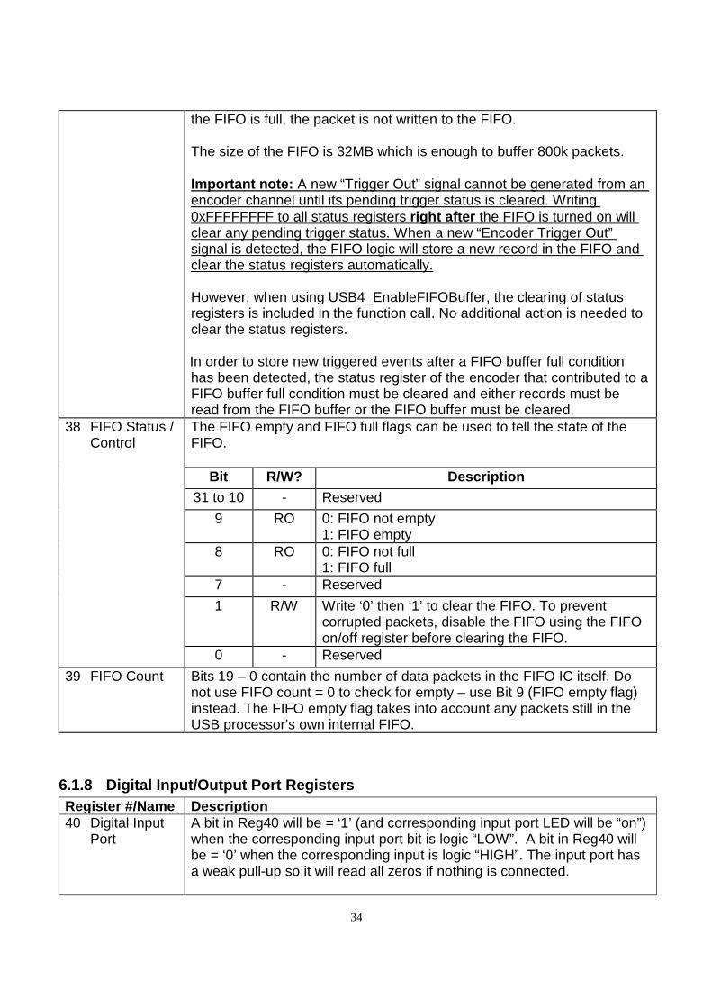
34
the FIFO is full, the packet is not written to the FIFO.
The size of the FIFO is 32MB which is enough to buffer 800k packets. Important note: A new “Trigger Out” signal cannot be generated from an encoder channel until its pending trigger status is cleared. Writing 0xFFFFFFFF to all status registers right after the FIFO is turned on will clear any pending trigger status. When a new “Encoder Trigger Out” signal is detected, the FIFO logic will store a new record in the FIFO and clear the status registers automatically. However, when using USB4_EnableFIFOBuffer, the clearing of status registers is included in the function call. No additional action is needed to clear the status registers. In order to store new triggered events after a FIFO buffer full condition has been detected, the status register of the encoder that contributed to a FIFO buffer full condition must be cleared and either records must be read from the FIFO buffer or the FIFO buffer must be cleared.
38 FIFO Status / Control
The FIFO empty and FIFO full flags can be used to tell the state of the FIFO.
Bit R/W? Description 31 to 10 - Reserved
9 RO 0: FIFO not empty 1: FIFO empty
8 RO 0: FIFO not full 1: FIFO full
7 - Reserved
1 R/W Write ‘0’ then ‘1’ to clear the FIFO. To prevent corrupted packets, disable the FIFO using the FIFO on/off register before clearing the FIFO.
0 - Reserved
39 FIFO Count Bits 19 – 0 contain the number of data packets in the FIFO IC itself. Do not use FIFO count = 0 to check for empty – use Bit 9 (FIFO empty flag) instead. The FIFO empty flag takes into account any packets still in the USB processor’s own internal FIFO.
6.1.8 Digital Input/Output Port Registers Register #/Name Description 40 Digital Input
Port A bit in Reg40 will be = ‘1’ (and corresponding input port LED will be “on”) when the corresponding input port bit is logic “LOW”. A bit in Reg40 will be = ‘0’ when the corresponding input is logic “HIGH”. The input port has a weak pull-up so it will read all zeros if nothing is connected.
35
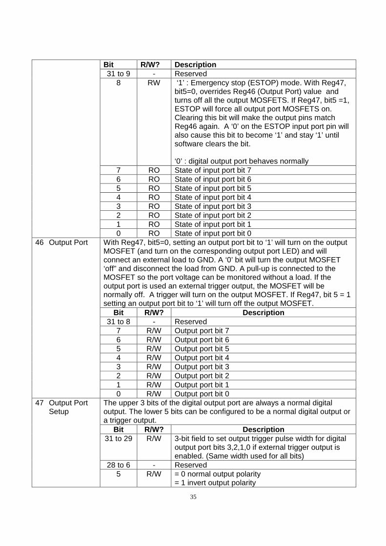
Bit R/W? Description 31 to 9 - Reserved
8 RW ‘1’ : Emergency stop (ESTOP) mode. With Reg47, bit5=0, overrides Reg46 (Output Port) value and turns off all the output MOSFETS. If Reg47, bit5 =1, ESTOP will force all output port MOSFETS on. Clearing this bit will make the output pins match Reg46 again. A ‘0’ on the ESTOP input port pin will also cause this bit to become ‘1’ and stay ‘1’ until software clears the bit. ‘0’ : digital output port behaves normally
7 RO State of input port bit 7 6 RO State of input port bit 6 5 RO State of input port bit 5 4 RO State of input port bit 4 3 RO State of input port bit 3 2 RO State of input port bit 2 1 RO State of input port bit 1 0 RO State of input port bit 0
46 Output Port With Reg47, bit5=0, setting an output port bit to ‘1’ will turn on the output MOSFET (and turn on the corresponding output port LED) and will connect an external load to GND. A ‘0’ bit will turn the output MOSFET ‘off” and disconnect the load from GND. A pull-up is connected to the MOSFET so the port voltage can be monitored without a load. If the output port is used an external trigger output, the MOSFET will be normally off. A trigger will turn on the output MOSFET. If Reg47, bit 5 = 1 setting an output port bit to ‘1’ will turn off the output MOSFET.
Bit R/W? Description 31 to 8 - Reserved
7 R/W Output port bit 7 6 R/W Output port bit 6 5 R/W Output port bit 5 4 R/W Output port bit 4 3 R/W Output port bit 3 2 R/W Output port bit 2 1 R/W Output port bit 1 0 R/W Output port bit 0
47 Output Port Setup
The upper 3 bits of the digital output port are always a normal digital output. The lower 5 bits can be configured to be a normal digital output or a trigger output.
Bit R/W? Description 31 to 29 R/W 3-bit field to set output trigger pulse width for digital
output port bits 3,2,1,0 if external trigger output is enabled. (Same width used for all bits)
28 to 6 - Reserved 5 R/W = 0 normal output polarity
= 1 invert output polarity
36
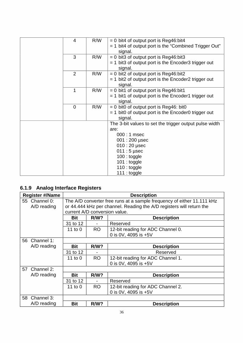
4 R/W = 0 bit4 of output port is Reg46:bit4 = 1 bit4 of output port is the “Combined Trigger Out”
signal. 3 R/W = 0 bit3 of output port is Reg46:bit3
= 1 bit3 of output port is the Encoder3 trigger out signal.
2 R/W = 0 bit2 of output port is Reg46:bit2 = 1 bit2 of output port is the Encoder2 trigger out
signal. 1 R/W = 0 bit1 of output port is Reg46:bit1
= 1 bit1 of output port is the Encoder1 trigger out signal.
0 R/W = 0 bit0 of output port is Reg46: bit0 = 1 bit0 of output port is the Encoder0 trigger out
signal. The 3-bit values to set the trigger output pulse width
are: 000 : 1 msec 001 : 200 µsec 010 : 20 µsec 011 : 5 µsec 100 : toggle 101 : toggle 110 : toggle 111 : toggle
6.1.9 Analog Interface Registers Register #/Name Description 55 Channel 0:
A/D reading The A/D converter free runs at a sample frequency of either 11.111 kHz or 44.444 kHz per channel. Reading the A/D registers will return the current A/D conversion value.
Bit R/W? Description 31 to 12 - Reserved 11 to 0 RO 12-bit reading for ADC Channel 0.
0 is 0V, 4095 is +5V
56 Channel 1: A/D reading
Bit R/W? Description
31 to 12 - Reserved 11 to 0 RO 12-bit reading for ADC Channel 1.
0 is 0V, 4095 is +5V
57 Channel 2: A/D reading
Bit R/W? Description
31 to 12 - Reserved 11 to 0 RO 12-bit reading for ADC Channel 2.
0 is 0V, 4095 is +5V
58 Channel 3: A/D reading
Bit R/W? Description
37
31 to 12 - Reserved 11 to 0 RO 12-bit reading for ADC Channel 3.
0 is 0V, 4095 is +5V
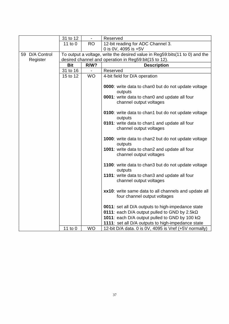
59 D/A Control Register
To output a voltage, write the desired value in Reg59:bits(11 to 0) and the desired channel and operation in Reg59:bit(15 to 12).
Bit R/W? Description 31 to 16 - Reserved 15 to 12 WO 4-bit field for D/A operation
0000: write data to chan0 but do not update voltage
outputs 0001: write data to chan0 and update all four
channel output voltages 0100: write data to chan1 but do not update voltage
outputs 0101: write data to chan1 and update all four
channel output voltages 1000: write data to chan2 but do not update voltage
outputs 1001: write data to chan2 and update all four
channel output voltages 1100: write data to chan3 but do not update voltage
outputs 1101: write data to chan3 and update all four
channel output voltages xx10 : write same data to all channels and update all
four channel output voltages 0011: set all D/A outputs to high-impedance state 0111: each D/A output pulled to GND by 2.5kΩ 1011: each D/A output pulled to GND by 100 kΩ 1111: set all D/A outputs to high-impedance state
11 to 0 WO 12-bit D/A data. 0 is 0V, 4095 is Vref (+5V normally)
38
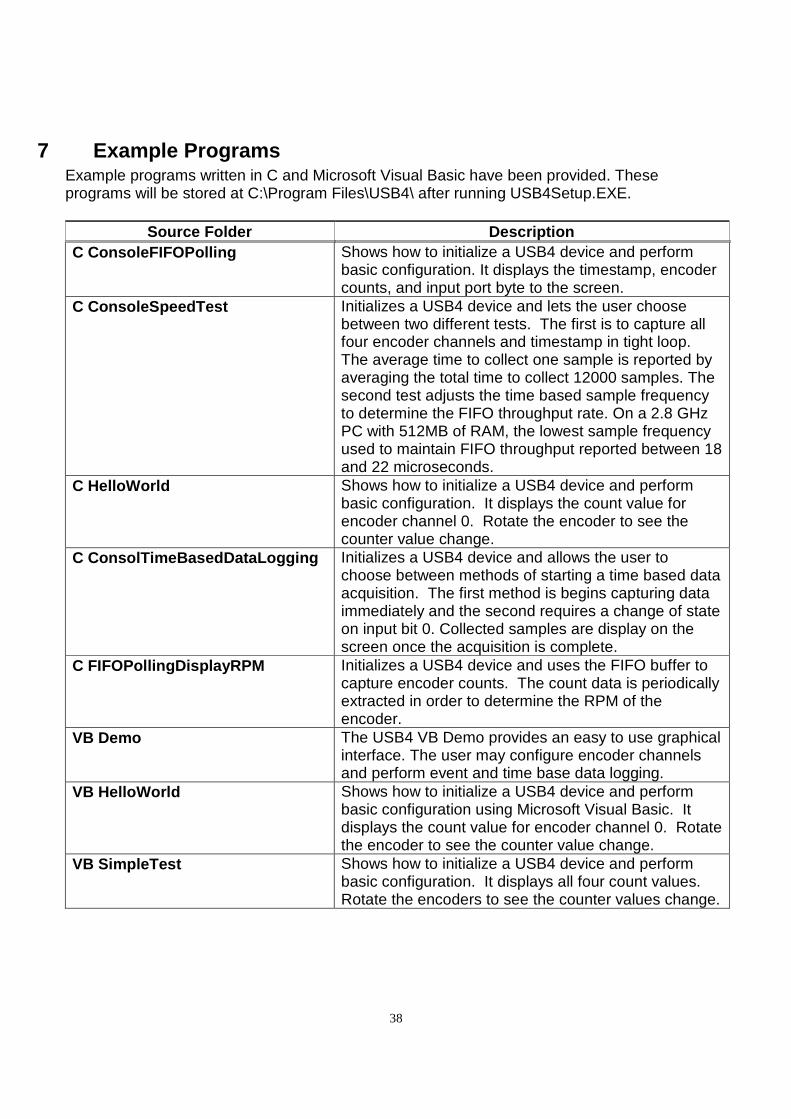
7 Example Programs Example programs written in C and Microsoft Visual Basic have been provided. These programs will be stored at C:\Program Files\USB4\ after running USB4Setup.EXE.
Source Folder Description C ConsoleFIFOPolling
Shows how to initialize a USB4 device and perform basic configuration. It displays the timestamp, encoder counts, and input port byte to the screen.
C ConsoleSpeedTest
Initializes a USB4 device and lets the user choose between two different tests. The first is to capture all four encoder channels and timestamp in tight loop. The average time to collect one sample is reported by averaging the total time to collect 12000 samples. The second test adjusts the time based sample frequency to determine the FIFO throughput rate. On a 2.8 GHz PC with 512MB of RAM, the lowest sample frequency used to maintain FIFO throughput reported between 18 and 22 microseconds.
C HelloWorld Shows how to initialize a USB4 device and perform basic configuration. It displays the count value for encoder channel 0. Rotate the encoder to see the counter value change.
C ConsolTimeBasedDataLogging Initializes a USB4 device and allows the user to choose between methods of starting a time based data acquisition. The first method is begins capturing data immediately and the second requires a change of state on input bit 0. Collected samples are display on the screen once the acquisition is complete.
C FIFOPollingDisplayRPM Initializes a USB4 device and uses the FIFO buffer to capture encoder counts. The count data is periodically extracted in order to determine the RPM of the encoder.
VB Demo The USB4 VB Demo provides an easy to use graphical interface. The user may configure encoder channels and perform event and time base data logging.
VB HelloWorld Shows how to initialize a USB4 device and perform basic configuration using Microsoft Visual Basic. It displays the count value for encoder channel 0. Rotate the encoder to see the counter value change.
VB SimpleTest Shows how to initialize a USB4 device and perform basic configuration. It displays all four count values. Rotate the encoders to see the counter values change.
39
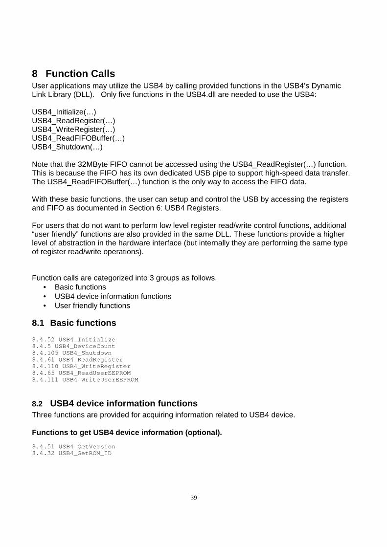
8 Function Calls User applications may utilize the USB4 by calling provided functions in the USB4’s Dynamic Link Library (DLL). Only five functions in the USB4.dll are needed to use the USB4: USB4_Initialize(…) USB4_ReadRegister(…) USB4_WriteRegister(…) USB4_ReadFIFOBuffer(…) USB4_Shutdown(…) Note that the 32MByte FIFO cannot be accessed using the USB4_ReadRegister(…) function. This is because the FIFO has its own dedicated USB pipe to support high-speed data transfer. The USB4_ReadFIFOBuffer(…) function is the only way to access the FIFO data. With these basic functions, the user can setup and control the USB by accessing the registers and FIFO as documented in Section 6: USB4 Registers. For users that do not want to perform low level register read/write control functions, additional “user friendly” functions are also provided in the same DLL. These functions provide a higher level of abstraction in the hardware interface (but internally they are performing the same type of register read/write operations). Function calls are categorized into 3 groups as follows.
• Basic functions • USB4 device information functions • User friendly functions
8.1 Basic functions 8.4.52 USB4_Initialize 8.4.5 USB4_DeviceCount 8.4.105 USB4_Shutdown 8.4.61 USB4_ReadRegister 8.4.110 USB4_WriteRegister 8.4.65 USB4_ReadUserEEPROM 8.4.111 USB4_WriteUserEEPROM
8.2 USB4 device information functions Three functions are provided for acquiring information related to USB4 device. Functions to get USB4 device information (optional) . 8.4.51 USB4_GetVersion 8.4.32 USB4_GetROM_ID
40
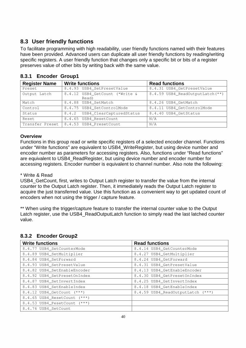
8.3 User friendly functions To facilitate programming with high readability, user friendly functions named with their features have been provided. Advanced users can duplicate all user friendly functions by reading/writing specific registers. A user friendly function that changes only a specific bit or bits of a register preserves value of other bits by writing back with the same value.
8.3.1 Encoder Group1 Register Name Write functions Read functions Preset 8.4.93 USB4_SetPresetValue 8.4.31 USB4_GetPresetValue
Output Latch 8.4.12 USB4_GetCount (*Write & Read)
8.4.59 USB4_ReadOutputLatch(**)
Match 8.4.88 USB4_SetMatch 8.4.26 USB4_GetMatch
Control 8.4.75 USB4_SetControlMode 8.4.11 USB4_GetControlMode
Status 8.4.2 USB4_ClearCapturedStatus 8.4.40 USB4_GetStatus
Reset 8.4.65 USB4_ResetCount N/A
Transfer Preset 8.4.53 USB4_PresetCount N/A
Overview Functions in this group read or write specific registers of a selected encoder channel. Functions under “Write functions” are equivalent to USB4_WriteRegister, but using device number and encoder number as parameters for accessing registers. Also, functions under “Read functions” are equivalent to USB4_ReadRegister, but using device number and encoder number for accessing registers. Encoder number is equivalent to channel number. Also note the following: * Write & Read USB4_GetCount, first, writes to Output Latch register to transfer the value from the internal counter to the Output Latch register. Then, it immediately reads the Output Latch register to acquire the just transferred value. Use this function as a convenient way to get updated count of encoders when not using the trigger / capture feature. ** When using the trigger/capture feature to transfer the internal counter value to the Output Latch register, use the USB4_ReadOutputLatch function to simply read the last latched counter value.
8.3.2 Encoder Group2 Write functions Read functions 8.4.77 USB4_SetCounterMode 8.4.14 USB4_GetCounterMode
8.4.89 USB4_SetMultiplier 8.4.27 USB4_GetMultiplier
8.4.84 USB4_SetForward 8.4.24 USB4_GetForward
8.4.93 USB4_SetPresetValue 8.4.31 USB4_GetPresetValue
8.4.82 USB4_SetEnableEncoder 8.4.13 USB4_GetEnableEncoder
8.4.92 USB4_SetPresetOnIndex 8.4.30 USB4_GetPresetO nIndex
8.4.87 USB4_SetInvertIndex 8.4.25 USB4_GetInvertInd ex
8.4.83 USB4_SetEnableIndex 8.4.18 USB4_GetEnableInd ex
8.4.12 USB4_GetCount (***) 8.4.59 USB4_ReadOutputLa tch (***)
8.4.65 USB4_ResetCount (***)
8.4.53 USB4_PesetCount (***)
8.4.76 USB4_SetCount
41
8.4.1 USB4_CaptureTimeAndCounts
8.4.62 USB4_ReadTimeAndCounts
Overview Functions in this group set-up other encoder counter functions. A typical set-up involves calling USB4_SetCounterMode, USB4_SetMultiplier and USB4_SetForward. If a counter mode other than ‘simple 24 bit counter’ is selected, USB4_SetPresetValue must be called to specify preset value. Call USB4_SetEnableEncoder to start the internal counter. If the encoder’s index pulse is used to reset or preset the counter value, call USB4_SetEnableIndex to enable the index features. USB4_SetPresetOnIndex will determine the action when index signal is detected, either resetting counter to 0 or presetting counter value equal to the value in preset register. USB4_SetInvertIndex changes the active polarity of the index pulse. USB4_SetEnableIndexOnMatch is used to enable the index features when the encoder counter value equals the match register value. When the match value is detected the index features are enabled. Once the index is detected and the counter is reset or preset the index features are disabled until the next match occurs. USB4_ResetCount or USB4_PresetCount forces internal counter’s value to zero or to the same as the Preset register, respectively. USB4_SetCount forces internal counter’s value to a specified value without permanently changing the Preset register. In fact, USB4_SetCount utilizes Preset register for transferring data to the internal counter, but the original value of Preset register is restored at the end of function call. When writing an application that always watches for changing of value of Preset register, the programmer must be aware of this temporary change of value. After USB4_SetEnableEncoder is called, the internal counter will be updated continuously based on signals input into A, B and Index pins. The internal counter may be read directly using USB4_ReadRegister to read Reg 5, Reg 13, Reg 21 or Reg 53. The Output Latch register is used to latch the internal counter. To get the latched count value, two steps are needed. First, the Output Latch register must be written (data does not matter) to transfer the internal count to the Output Latch register. Second, the Output Latch register is read to retrieve the latched value. These two steps are combined in USB4_GetCount function. This function is recommended when not using the trigger / capture feature. USB4_ReadOutputLatch is normally called when the trigger / latch feature is in use. A trigger event will automatically transfer the count value from the internal counter to the Output Latch register. USB4_ReadTimeAndCounts simply reads the Timestamp Latch and each of the encoder’s Output Latch while USB4_CaptureTimeAndCounts causes a synchronized capture of the Timestamp counter and all channel Encoders that have captured enabled set true. Function USB4_Get... under “Read functions” may be used to verify the USB4_Set... counterparts.
42
8.3.3 Time Stamp Group Write functions Read functions 8.4.63 USB4_ReadTimeStamp 8.4.67 USB4_ResetTimeStamp 8.4.43 USB4_GetTimeStamp
Overview USB4_ReadTimeStamp simply reads the Time Stamp Latch without causing the Time Stamp Counter to be transferred to the Time Stamp Latch. USB4_ResetTimeStamp sets the Time Stamp Counter value to zero. USB4_GetTimeStamp writes to the Command Register which causes the Time Stamp Counter to be latched to the Time Stamp Latch and then reads the Time Stamp Latch.
8.3.4 Trigger/Capture Feature Group Capture Functions Write functions Read functions 8.4.68 USB4_SetCaptureEnabled 8.4.9 USB4_GetCaptureEnabled
Trigger Functions Write functions Read functions 8.4.88 USB4_SetMatch 8.4.26 USB4_GetMatch
8.4.99 USB4_SetTriggerOnIncrease 8.4.45 USB4_GetTri ggerOnIncrease
8.4.100 USB4_SetTriggerOnIndex 8.4.46 USB4_GetTrigg erOnIndex
8.4.101 USB4_SetTriggerOnMatch 8.4.47 USB4_GetTrigg erOnMatch
8.4.94 USB4_SetTriggerOnDecrease 8.4.44 USB4_GetTri ggerOnDecrease
8.4.102 USB4_SetTriggerOnRollover 8.4.48 USB4_GetTr iggerOnRollover
8.4.103 USB4_SetTriggerOnRollunder 8.4.49 USB4_GetT riggerOnRollunder
8.4.104 USB4_SetTriggerOnZero 8.4.50 USB4_GetTrigge rOnZero
8.4.2 USB4_ClearCapturedStatus 8.4.40 USB4_GetStat us 8.4.41 USB4_GetStatusEX
Overview An encoder channel may be configured to generate a trigger signal when various conditions are met. This trigger signal is forwarded to all encoder channels. If a channel has capture enabled, it will then transfer the internal counter value to the Output Latch register. The trigger signal will also transfer the Time Stamp Counter to the Time Stamp Latch regardless of any channel having capture enabled. Function USB4_Get... under “Read functions” may be used to verify their USB4_Set... counterparts.
8.3.5 First-In-First-Out (FIFO) Buffer Handling Gro up
43
8.4.4 USB4_ClearFIFOBuffer 8.4.6 USB4_DisableFIFOBuffer 8.4.7 USB4_EnableFIFOBuffer 8.4.20 USB4_GetFIFOBufferCount 8.4.56 USB4_ReadFIFOBuffer 8.4.57 USB4_ReadFIFOBufferStruct
Overview Six functions are provided that support the FIFO buffering feature related to USB4 device. The FIFO can be enabled using USB4_EnableFIFOBuffer. The USB4_GetFIFOBufferCount returns the number of 40-byte data packets currently stored in the FIFO buffer. The FIFO buffer can hold up to 800k data packets. For details of the FIFO structure please see 6.1.7 FIFO Control/Status Registers. USB4_ClearFIFOBuffer resets the FIFO buffer. USB4_ReadFIFOBuffer or USB4_ReadFIFOBufferStruct is used to read stored records in the FIFO buffer. USB4_DisableFIFOBuffer disables the FIFO feature.
8.3.6 Digital Input Triggering Group 8.4.79 USB4_SetDigitalInputTriggerConfig 8.4.15 USB4_GetDigitalInputTriggerConfig 8.4.3 USB4_ClearDigitalInputTriggerStatus 8.4.17 USB4_GetDigitalInputTriggerStatus
Overview Digital Input Triggering is a quick and easy way to capture encoder counts along with time stamp based on the rising or falling edge of external digital inputs. When the specified edge is detected on an input pin, the status of that input pin is set and the encoder counts with time stamp are latched to the Output Latch registers(reg.#1, reg.#9, and reg.#17) and the Time Stamp Latch register (reg.#15). There are 8 input pins. Each input pin has its own status bit and works independently. The status bit must be cleared using USB4_ClearDigitalInputTriggerStatus before the same pin can be used to detect the trigger signal. However, the status bits can also be cleared automatically when the FIFO buffer is enabled by USB4_EnableFIFOBuffer. While the FIFO buffer is enabled, the captured encoder counts and the time stamp are also stored in the FIFO.
8.3.7 Data Logging and Input/Output Group 8.4.94 USB4_SetSamplesToCollect 8.4.37 USB4_GetSamp lesToCollect 8.4.96 USB4_SetSamplingRateMultiplier 8.4.39 USB4_G etSamplingRateMultiplier 8.4.97 USB4_SetTimeBasedLogSettings 8.4.42 USB4_Get TimeBasedLogSettings 8.4.106 USB4_StartAcquisition 8.4.107 USB4_StopAcqu isition 8.4.91 USB4_SetOutputPortConfig 8.4.29 USB4_GetOutp utPortConfig 8.4.109 USB4_WriteOutputPortRegister 8.4.60 USB4_Re adOutputPortRegister 8.4.58 USB4_ReadInputPortRegister 8.4.38 USB4_GetSamplingRateCounter 8.4.35 USB4_GetSamplesRemaining
Overview USB4_SetSamplingRateMultiplier sets the 32 bit sampling rate multiplier (N) which is used to determine the sampling period. The data logging is synchronized precisely to this sampling period. USB4_SetTimeBasedLogSettings determines the input condition that must be satisfied in order to start a data acquisition. USB4_SetSamplesToCollect sets the number of samples to be collected when an acquisition is started. USB4_StartAcquisition starts the acquisition. The
44
data acquisition will stop once the specified number of data has been reached or if the FIFO is full. USB4_StopAcquisition can be used to abort the acquisition in progress. During data acquisition, USB4_GetSamplesRemaining can be used to retrieve the number of samples remaining to be collected. USB4_ReadInputPortRegister returns the value stored in the input port register. USB4_WriteOutputPortRegister sets the value stored in the output port register. USB4_ReadOutputPortRegister read back the valued stored in the output port register. USB4_SetOutputPortConfig is used to configure the output port setup. The output port pins may be driven by the output port register or trigger out signals. If the trigger out signals are used to drive the output port, then the length of the output trigger signal may also be specified. USB4_GetSamplesToCollect, USB4_GetSamplingRateMultiplier, USB4_GetTimeBasedLogSettings, USB4_GetOutputPortConfig retrieve values of each setting. USB4_GetSamplingRateCounter retrieves the current value of the sampling rate counter.
45
8.4 Function Definitions
8.4.1 USB4_CaptureTimeAndCounts Description: This function causes a software capture (Register 7:bit 4) of the Timestamp counter and all channel encoders which have “captured enabled” set true. C Language Function Prototype: int _stdcall USB4_CaptureTimeAndCounts(short iDevic eNo, unsigned long *pulCounts, unsigned long *pulTimeStamp);
Returns: Result code as an integer: See error code section for values other than zero. Zero implies function call is successful. Parameters: iDeviceNo : identifies the USB4 device (zero based). pulCounts : array of 4 unsigned longs containing the latched counter value (unsigned 24-bit
integer) pulTimeStamp : contains the latched Timestamp value.
Example C Usage: int iResult = USB4_SUCCESS; short iDeviceNo = 0; unsigned long ulCounts[4] = 0, 0, 0, 0; unsigned long ulTimeStamp = 0; iResult = USB4_CaptureTimeAndCounts(iDeviceNo, &ulC ounts, &ulTimeStamp); if ( iResult != USB4_SUCCESS ) // Handle error...
VB Language Function Declaration: Public Declare Function USB4_CaptureTimeAndCounts L ib "USB4.dll" (ByVal iDeviceNo As Integer, ByRef pulCounts As Long, ByRef pulTimeStam p As Long) As Long
Example VB Usage: Dim errCode As Long Dim iDeviceNo As Integer Dim lCounts(3) As Long Dim lTimeStamp As Long iDeviceNo = 0 errCode = USB4_CaptureTimeAndCounts(iDeviceNo, lCou nts(0), lTimeStamp) If errCode <> USB4_SUCCESS then ‘ Handle error... End If
46
8.4.2 USB4_ClearCapturedStatus Description: This function clears the captured event status by writing 0xFFFFFFFF into the status register of the specified encoder channel.
Note: Refer to section 6.1.1 Incremental Encoder Registers.
C Language Function Prototype: int _stdcall USB4_ClearCapturedStatus(short iDevice No, short iEncoder); Returns: Result code as an integer: See error code section for values other than zero. Zero implies function call is successful. Parameters: iDeviceNo : identifies the USB4 device (zero based). iEncoder: identifies the encoder channel (zero based, 0-3) Example C Usage: int iResult = USB4_SUCCESS; short iDeviceNo = 0; short iEncoder = 0; iResult = USB4_ClearCapturedStatus(iDeviceNo, iEnco der); if ( iResult != USB4_SUCCESS ) // Handle error...
VB Language Function Declaration: Public Declare Function USB4_ClearCapturedStatus Li b "USB4.dll" (ByVal iDeviceNo As Integer, ByVal iEncoder As Integer) As Long
Example VB Usage: Dim errCode As Long Dim iDeviceNo As Integer Dim iEncoder As Integer iDeviceNo = 0 iEncoder = 0 errCode = USB4_ClearCapturedStatus(iDeviceNo, iEnco der) If errCode <> USB4_SUCCESS then ‘ Handle error... End If
47
8.4.3 USB4_ClearDigitalInputTriggerStatus Description: This function clears the digital input detected status for each input by writing 0xFFFFFFFF to the digital input status register. Note: Refer to section 6.1.4 Event Based Trigger - Input Port Simple External Trigger Registers C Language Function Prototype: int _stdcall USB4_ClearDigitalInputTriggerStatus(sh ort iDeviceNo); Returns: Result code as an integer: See error code section for values other than zero. Zero implies function call is successful. Parameters: iDeviceNo : identifies the USB4 device (zero based). Example C Usage: int iResult = USB4_SUCCESS; short iDeviceNo = 0; iResult = USB4_ClearDigitalInputTriggerStatus(iDevi ceNo); if ( iResult != USB4_SUCCESS ) // Handle error...
VB Language Function Declaration: Public Declare Function USB4_ClearDigitalInputTrigg erStatus Lib "USB4.dll" (ByVal iDeviceNo As Integer) As Long
Example VB Usage: Dim errCode As Long Dim iDeviceNo As Integer iDeviceNo = 0 errCode = USB4_ClearDigitalInputTriggerStatus(iDevi ceNo) If errCode <> USB4_SUCCESS then ‘ Handle error... End If
48
8.4.4 USB4_ClearFIFOBuffer Description: This function flushes the FIFO buffer. C Language Function Prototype: int _stdcall USB4_ClearFIFOBuffer(short iDeviceNo);
Returns: Result code as an integer: See error code section for values other than zero. Zero implies function call is successful. Parameters: iDeviceNo : identifies the USB4 device (zero based).
Example C Usage: int iResult = USB4_SUCCESS; short iDeviceNo = 0; iResult = USB4_ClearFIFOBuffer(iDeviceNo); if ( iResult != USB4_SUCCESS ) // Handle error...
VB Language Function Declaration: Public Declare Function USB4_ClearFIFOBuffer Lib "U SB4.dll" (ByVal iDeviceNo As Integer) As Long
Example VB Usage: Dim errCode As Long Dim iDeviceNo As Integer iDeviceNo = 0 errCode = USB4_ClearFIFOBuffer (iDeviceNo) If errCode <> USB4_SUCCESS then ‘ Handle error... End If
49
8.4.5 USB4_DeviceCount Description: This function returns the number of USB4 devices detected. The value returned should be the same value as returned in the piDeviceCount parameter of the USB4_Initialize function. C Language Function Prototype: int _stdcall USB4_DeviceCount();
Returns: See description above. Parameters: None
Example C Usage: short iDevices = USB4_DeviceCount();
VB Language Function Declaration: Public Declare Function USB4_DeviceCount Lib "USB4. dll" () As Long
Example VB Usage: Dim iDevices As Integer iDevices = USB4_DeviceCount()
50
8.4.6 USB4_DisableFIFOBuffer Description: This function disables the FIFO buffering feature and disables auto clearing of captured event status and digital input trigger status. C Language Function Prototype: int _stdcall USB4_DisableFIFOBuffer(short iDeviceNo );
Returns: Result code as an integer: See error code section for values other than zero. Zero implies function call is successful. Parameters: iDeviceNo : identifies the USB4 device (zero based).
Example C Usage: int iResult = USB4_SUCCESS; short iDeviceNo = 0; iResult = USB4_DisableFIFOBuffer(iDeviceNo); if ( iResult != USB4_SUCCESS ) // Handle error...
VB Language Function Declaration: Public Declare Function USB4_DisableFIFOBuffer Lib "USB4.dll" (ByVal iDeviceNo As Integer) As Long
Example VB Usage: Dim errCode As Long Dim iDeviceNo As Integer iDeviceNo = 0 errCode = USB4_DisableFIFOBuffer (iDeviceNo) If errCode <> USB4_SUCCESS then ‘ Handle error... End If
51
8.4.7 USB4_ EnableFIFOBuffer Description: This function enables the FIFO buffering feature and enables auto clearing of captured event status and digital input trigger status. C Language Function Prototype: int _stdcall USB4_EnableFIFOBuffer(short iDeviceNo) ;
Returns: Result code as an integer: See error code section for values other than zero. Zero implies function call is successful. Parameters: iDeviceNo : identifies the USB4 device (zero based).
Example C Usage: int iResult = USB4_SUCCESS; short iDeviceNo = 0; iResult = USB4_EnableFIFOBuffer(iDeviceNo); if ( iResult != USB4_SUCCESS ) // Handle error...
VB Language Function Declaration: Public Declare Function USB4_EnableFIFOBuffer Lib " USB4.dll" (ByVal iDeviceNo As Integer) As Long
Example VB Usage: Dim errCode As Long Dim iDeviceNo As Integer iDeviceNo = 0 errCode = USB4_EnableFIFOBuffer(iDeviceNo) If errCode <> USB4_SUCCESS then ‘ Handle error... End If
52
8.4.8 USB4_GetA2D Description: This function reads the current 12-bit value from a specified analog to digital (A2D) converter channel. The A2D converter free runs at either 11.111 kHz or 44.444 kHz. C Language Function Prototype: int _stdcall USB4_GetCA2D (short iDeviceNo, short i A2DChannel, usigned short *puiA2DValue);
Returns: Result code as an integer: See error code section for values other than zero. Zero implies function call is successful. Parameters: iDeviceNo : identifies the USB4 device (zero based). iEncoder : identifies a specified A2D channel (0-3). puiA2DValue : contains the reading from the specified A2D channel from 0 (0V) to 4095 (5V). Example C Usage: int iResult = USB4_SUCCESS; short iDeviceNo = 0; short iA2DChannel = 1; unsigned short uiA2DValue = 0; iResult = USB4_GetA2D(iDeviceNo, iA2DChannel, &uiA2 DValue); if ( iResult != USB4_SUCCESS ) // Handle error...
VB Language Function Declaration: Public Declare Function USB4_GetA2D Lib "USB4.dll" (ByVal iDeviceNo As Integer, ByVal iA2DChannel As Integer, ByRef puiA2DValue As Intege r) As Long
Example VB Usage: Dim errCode As Long Dim iDeviceNo As Integer Dim iA2DChannel As Integer Dim uiA2DVal As Integer iDeviceNo = 0 iA2DChannel = 1 errCode = USB4_GetA2D(iDeviceNo, iA2DChannel, puiA2 DValue) If errCode <> USB4_SUCCESS then ‘ Handle error... End If
53
8.4.9 USB4_GetA2DSamplingFrequency Description: This function retrieves the Current A/D Sampling Frequency flag which is contained in bit 7 of the Command register. If this bit is clear (0), the A/D sampling frequency is 11.111 kHz. If this bit is set (1), the A/D sampling frequency is 44.444 kHz. C Language Function Prototype: int _stdcall USB4_GetA2DSamplingFrequency(short iDe viceNo, unsigned short * puiVal);
Returns: Result code as an integer: See error code section for values other than zero. Zero implies function call is successful. Parameters: iDeviceNo : identifies the USB4 device (zero based). puiVal : contains the A/D Sampling Frequency flag 0 = 11.111 kHz
1 = 44.444 kHz Example C Usage: int iResult = USB4_SUCCESS; short iDeviceNo = 0; unsigned short uiA2DSamplingFrequencyFlag = 0; iResult = USB4_GetA2DSamplingFrequency(iDeviceNo, u iA2DSamplingFrequencyFlag); if ( iResult != USB4_SUCCESS ) // Handle error...
VB Language Function Declaration: Public Declare Function USB4_GetA2DSamplingFrequenc y Lib "USB4.dll" (ByVal iDeviceNo As Integer, ByRef puiVal As Integer) As Long
Example VB Usage: Dim errCode As Long Dim iDeviceNo As Integer Dim uiA2DSamplingFrequencyFlag As Integer iDeviceNo = 0 errCode = USB4_GetA2DSamplingFrequency(iDeviceNo, u iA2DSamplingFrequencyFlag) If errCode <> USB4_SUCCESS then ‘ Handle error... End If
54
8.4.10 USB4_GetCaptureEnabled Description: This function retrieves a Boolean value that identifies if trigger_in causes a transfer from the encoder counter to the output latch C Language Function Prototype: int _stdcall USB4_GetCaptureEnabled(short iDeviceNo , short iEncoder, BOOL *pbVal);
Returns: Result code as an integer: See error code section for values other than zero. Zero implies function call is successful. Parameters: iDeviceNo : identifies the USB4 device (zero based). iEncoder: identifies the encoder channel (zero based, 0-3). pbVal : parameter that indentifies if the capture feature is enabled. TRUE = enabled. FALSE = disabled. Example C Usage: int iResult = USB4_SUCCESS; short iDeviceNo = 0; short iEncoder = 0; BOOL bVal = 0; iResult = USB4_GetCaptureEnabled(iDeviceNo, iEncode r, &bVal); if ( iResult != USB4_SUCCESS ) // Handle error...
VB Language Function Declaration: Public Declare Function USB4_GetCaptureEnabled Lib "USB4.dll" (ByVal iDeviceNo As Integer, ByVal iEncoder As Integer, ByRef pbVal As Long) As Long
Example VB Usage: Dim errCode As Long Dim iDeviceNo As Integer Dim iEncoder As Integer Dim bVal As Long iDeviceNo = 0 iEncoder = 0 errCode = USB4_GetCaptureEnabled(iDeviceNo, iEncode r, bVal) If errCode <> USB4_SUCCESS then ‘ Handle error... End If
55
8.4.11 USB4_GetControlMode Description: This function reads the 32-bit Control register for the specified encoder channel. See section 6.1.1 Incremental Encoder Registers C Language Function Prototype: int _stdcall USB4_GetControlMode(short iDeviceNo, s hort iEncoder, unsigned long *pulVal); Returns: Result code as an integer: See error code section for values other than zero. Zero implies function call is successful. Parameters: iDeviceNo : identifies the USB4 device (zero based). iEncoder: identifies the encoder channel (zero based, 0-3). pulVal : contains the value read from the Control register. Example C Usage: int iResult = USB4_SUCCESS; short iDeviceNo = 0; short iEncoder = 0; unsigned long ulVal = 0; iResult = USB4_GetControlMode(iDeviceNo, iEncoder, &ulVal ); if ( iResult != USB4_SUCCESS ) // Handle error...
VB Language Function Declaration: Public Declare Function USB4_GetControlMode Lib "US B4.dll" (ByVal iDeviceNo As Integer, ByVal iEncoder As Integer, ByRef pulVal As Long) As Long
Example VB Usage: Dim errCode As Long Dim iDeviceNo As Integer Dim iEncoder As Integer Dim lVal As Long iDeviceNo = 0 iEncoder = 0 errCode = USB4_GetControlMode(iDeviceNo, iEncoder, lVal) If errCode <> USB4_SUCCESS then ‘ Handle error... End If
56
8.4.12 USB4_GetCount Description: This function gets the count value for the specified encoder channel. This function performs the following two steps: (1) Write to Output Latch register (reg. #1, reg. #9, reg. #17, or reg. #49 based on channel selected). This action will transfer the value from internal counter register to the Output Latch register. (2) Read from Output Latch register (reg. #1, reg. #9, reg. #17, or reg. #49 based on channel selected). The result of this read is the updated value from the Output Latch register which is passed to pulVal. Caveats: This USB4_GetCount is a convenient function to easily get encoder counts from USB4. However, if you want to use triggering features of USB4 to transfer data from internal counter to Output Latch register, you should use USB4_ReadRegister instead of USB4_GetCount. In this case, using USB4_GetCount to read data will result in overwriting the output latch count value when a trigger event occurs. C Language Function Prototype: int _stdcall USB4_GetCount(short iDeviceNo, short i Encoder, BOOL *pbVal);
Returns: Result code as an integer: See error code section for values other than zero. Zero implies function call is successful. Parameters: iDeviceNo : identifies the USB4 device (zero based). iEncoder: identifies the encoder channel (zero based, 0-3). pulVal : contains the encoder count value. Example C Usage: int iResult = USB4_SUCCESS; short iDeviceNo = 0; short iEncoder = 0; BOOL bVal = 0; iResult = USB4_GetCount(iDeviceNo, iEncoder, &bVal) ; if ( iResult != USB4_SUCCESS ) // Handle error...
57
VB Language Function Declaration: Public Declare Function USB4_GetCount Lib "USB4.dll " (ByVal iDeviceNo As Integer, ByVal iEncoder As Integer, ByRef pulVal As Long) As Long
Example VB Usage: Dim errCode As Long Dim iDeviceNo As Integer Dim iEncoder As Integer Dim lVal As Long iDeviceNo = 0 iEncoder = 0 errCode = USB4_GetCount(iDeviceNo, iEncoder, lVal) If errCode <> USB4_SUCCESS then ‘ Handle error... End If
58
8.4.13 USB4_GetCounterEnabled Description: This function retrieves a boolean value that indicates whether the master enable for the specified encoder channel is set C Language Function Prototype: int _stdcall USB4_GetCounterEnabled(short iDeviceNo , short iEncoder, BOOL *pbVal);
Returns: Result code as an integer: See error code section for values other than zero. Zero implies function call is successful. Parameters: iDeviceNo : identifies the USB4 device (zero based). iEncoder: identifies the encoder channel (zero based, 0-3). pbVal : boolean parameter identifying whether the counter is enabled TRUE = enabled. FALSE = disabled. Example C Usage: int iResult = USB4_SUCCESS; short iDeviceNo = 0; short iEncoder = 0; BOOL bVal = FALSE; iResult = USB4_GetCounterEnabled(iDeviceNo, iEncode r, &bVal); if ( iResult != USB4_SUCCESS ) // Handle error...
VB Language Function Declaration: Public Declare Function USB4_GetCounterEnabled Lib "USB4.dll" (ByVal iDeviceNo As Integer, ByVal iEncoder As Integer, ByRef pbVal As Long) As Long
Example VB Usage: Dim errCode As Long Dim iDeviceNo As Integer Dim iEncoder As Integer Dim bVal As Long iDeviceNo = 0 iEncoder = 0 errCode = USB4_GetCounterEnabled(iDeviceNo, iEncode r, bVal) If errCode <> USB4_SUCCESS then ‘ Handle error... End If
59
8.4.14 USB4_GetCounterMode Description: This function gets the counter mode for the specified channel. See parameters sections for description of the possible counter modes. C Language Function Prototype: int _stdcall USB4_GetCounterMode(short iDeviceNo, s hort iEncoder, short *piVal); Returns: Result code as an integer: See error code section for values other than zero. Zero implies function call is successful. Parameters: iDeviceNo : identifies the USB4 device (zero based). iEncoder: identifies the encoder channel (zero based, 0-3). piVal : parameter containing the counter mode. 0 = 24-bit counter. 1 = 24-bit counter with preset register in range-limit mode . 2 = 24-bit counter with preset register in non-recycle mode. 3 = 24-bit counter with preset register in modulo-N mode.
See 6.1 Control Registers for explanation of modes. Example C Usage: int iResult = USB4_SUCCESS; short iDeviceNo = 0; short iEncoder = 0; short iVal = 0; iResult = USB4_GetControlMode(iDeviceNo, iEncoder, &iVal); if ( iResult != USB4_SUCCESS ) // Handle error...
VB Language Function Declaration: Public Declare Function USB4_GetCounterMode Lib "US B4.dll" (ByVal iDeviceNo As Integer, ByVal iEncoder As Integer, ByRef piVal As Integer) As Long
Example VB Usage: Dim errCode As Long Dim iDeviceNo As Integer Dim iEncoder As Integer Dim iVal As Integer iDeviceNo = 0 iEncoder = 0 errCode = USB4_GetCounterMode(iDeviceNo, iEncoder, iVal) If errCode <> USB4_SUCCESS then ‘ Handle error... End If
60
8.4.15 USB4_GetDeviceNo Description: This function retrieves the corresponding device number for a specified module address. A module address is a single byte number that can be stored in a USB4’s EEPROM. The module address is often used to identify a specific device. As each USB4 device is enumerated on the USB bus it is assigned a device number. This device number is used by each USB4 function to access the device’s internal registers. If only one USB4 device is attached to the host PC, then its device number will be 0. C Language Function Prototype: int _stdcall USB4_GetDeviceNo(unsigned char ucModul eAddress, short * piDeviceNo); Returns: Result code as an integer: See error code section for values other than zero. Zero implies function call is successful. Parameters: ucModuleAddress : identifies the USB4’s module address (zero based). piDeviceNo : identifies the USB4 device (zero based). Example C Usage: int iResult = USB4_SUCCESS; unsigned char ucModuleAddress = 16; // Example only . short iDeviceNo = 0; iResult = USB4_GetDeviceNo(ucModuleAddress, &iDevic eNo); if ( iResult != USB4_SUCCESS ) // Handle error...
VB Language Function Declaration: Public Declare Function USB4_GetDeviceNo Lib "USB4. dll" (ByVal bytModuleAddress, ByRef iDeviceNo As Integer) As Long
Example VB Usage: Dim errCode As Long Dim bytModuleAddress As Byte Dim iDeviceNo As Integer bytModuleAddress = 16 ‘ Example only. iDeviceNo = 0 errCode = USB4_GetDeviceNo(bytModuleAddress, iDevic eNo) If errCode <> USB4_SUCCESS then ‘ Handle error... End If
61
8.4.16 USB4_GetDigitalInputTriggerConfig Description: This function retrieves the digital input trigger configuration settings. Note: Refer to section 6.1.4 Event Based Trigger - Input Port Simple External Trigger Registers C Language Function Prototype: int _stdcall USB4_GetDigitalInputTriggerConfig(shor t iDeviceNo, BOOL *pbEnableTrigger, BOOL *pbTriggerOnRisingEdge);
Returns: Result code as an integer: See error code section for values other than zero. Zero implies function call is successful. Parameters: iDeviceNo : identifies the USB4 device (zero based). pbEnableTrigger : array of eight booleans which enable/disable trigger generation for each
digital input pin. TRUE = trigger enabled. FALSE = trigger disabled. pbTriggerOnRisingEdge : array of eight booleans which determine the trigger’s active edge for
each digital input pin. TRUE = rising edge. FALSE = falling edge. Example C Usage: int iResult = USB4_SUCCESS; int iDeviceNo = 0; BOOL bEnableTrigger[8]; BOOL bTriggerOnRisingEdge[8]; iResult = USB4_GetDigitalInputTriggerConfig(iDevice No, bEnableTrigger, bTriggerOnRisingEdge); if ( iResult != USB4_SUCCESS ) // Handle error...
VB Language Function Declaration: Public Declare Function USB4_GetDigitalInputTrigger Config Lib "USB4.dll" (ByVal iDeviceNo As Integer, ByRef bEnableTrigger As Long, ByRef bTriggerOnRisingEdge As Long) As Long
Example VB Usage: Dim errCode As Long Dim iDeviceNo As Integer Dim bEnableTrigger(7) As Long Dim bTriggerOnRisingEdge (7) As Long iDeviceNo = 0 errCode = USB4_GetDigitalInputTriggerConfig (iDevic eNo, bEnableTrigger(0), bTriggerOnRisingEdge(0)) If errCode <> USB4_SUCCESS then ‘ Handle error... End If
62
8.4.17 USB4_GetDigitalInputTriggerStatus Description: This function retrieves the digital input trigger event detected status. Note: Refer to section 6.1.4 Event Based Trigger - Input Port Simple External Trigger Registers C Language Function Prototype: int _stdcall USB4_GetDigitalInputTriggerStatus(shor t iDeviceNo, BOOL *pbVal);
Returns: Result code as an integer: See error code section for values other than zero. Zero implies function call is successful. Parameters: iDeviceNo : identifies the USB4 device (zero based). pbVal : an array of 8 Booleans that identify if digital input triggers have occured Example C Usage: int iResult = USB4_SUCCESS; int iDeviceNo = 0; BOOL bVal[8]; iResult = USB4_GetDigitalInputTriggerStatus(iDevice No, bVal); if ( iResult != USB4_SUCCESS ) // Handle error...
VB Language Function Declaration: Public Declare Function USB4_GetDigitalInputTrigger Status Lib "USB4.dll" (ByVal iDeviceNo As Integer, ByRef pbVal As Long) As Long
Example VB Usage: Dim errCode As Long Dim iDeviceNo As Integer Dim bVal(7) As Long iDeviceNo = 0 errCode = USB4_GetDigitalInputTriggerStatus(iDevice No, bVal(0)) If errCode <> USB4_SUCCESS then ‘ Handle error... End If
63
8.4.18 USB4_GetDriverBuildNumber Description: This function retrieves the firmware version number. C Language Function Prototype: int _stdcall USB4_GetDriverBuildNumber(short iDevic eNo, unsigned char *pucVersion); Returns: Result code as an integer: See error code section for values other than zero. Zero implies function call is successful. Parameters: iDeviceNo : identifies the USB4 device (zero based). pucVersion: parameter containing the firmware version number. Example C Usage: int iResult = USB4_SUCCESS; short iDeviceNo = 0; unsigned char ucVersion = 0; iResult = USB4_GetDriverBuildNumber (iDeviceNo, &uc Version); if ( iResult != USB4_SUCCESS ) // Handle error...
VB Language Function Declaration: Public Declare Function USB4_GetDriverBuildNumber L ib "USB4.dll" (ByVal iDeviceNo As Integer, ByRef bytVersion As Byte) As Long
Example VB Usage: Dim errCode As Long Dim iDeviceNo As Integer Dim bytVersion as Byte iDeviceNo = 0 errCode = USB4_GetCounterMode(iDeviceNo, bytVersion ) If errCode <> USB4_SUCCESS then ‘ Handle error... End If
64
8.4.19 USB4_GetEnableIndex Description: This function retrieves a boolean value that indicates whether index detection is enabled for the specified encoder channel. When enabled, USB4_SetPresetOnIndex can be used to determine how to respond to an index signal. C Language Function Prototype: int _stdcall USB4_GetEnableIndex(short iDeviceNo, s hort iEncoder, BOOL *pbVal); Returns: Result code as an integer: See error code section for values other than zero. Zero implies function call is successful. Parameters: iDeviceNo : identifies the USB4 device (zero based). iEncoder: identifies the encoder channel (zero based, 0-3). pbVal : boolean parameter identifying whether the index is enabled. Example C Usage: int iResult = USB4_SUCCESS; short iDeviceNo = 0; short iEncoder = 0; BOOL bVal = FALSE; iResult = USB4_GetEnableIndex(iDeviceNo, iEncoder, &bVal); if ( iResult != USB4_SUCCESS ) // Handle error...
VB Language Function Declaration: Public Declare Function USB4_GetEnableIndex Lib "US B4.dll" (ByVal iDeviceNo As Integer, ByVal iEncoder As Integer, ByRef pbVal As Long) As Long
Example VB Usage: Dim errCode As Long Dim iDeviceNo As Integer Dim iEncoder As Integer Dim bVal As Long iDeviceNo = 0 iEncoder = 0 errCode = USB4_GetEnableIndex(iDeviceNo, iEncoder, bVal) If errCode <> USB4_SUCCESS then ‘ Handle error... End If
65
8.4.20 USB4_GetEStopBit Description: This function retrieves the latched E-Stop (emergency stop) state C Language Function Prototype: int _stdcall USB4_GetEStopBit(short iDeviceNo, unsi gned char *pbVal)
Returns: Result code as an integer: See error code section for values other than zero. Zero implies function call is successful. Parameters: iDeviceNo : identifies the USB4 device (zero based). pbVal : contains the latched emergency stop state. 0x01 = E-Stop active 0x00 = E-Stop inactive Example C Usage: int iResult = USB4_SUCCESS; short iDeviceNo = 0; unsigned char bVal = 0; iResult = USB4_GetEStopBit(iDeviceNo, & bVal); if ( iResult != USB4_SUCCESS ) // Handle error...
VB Language Function Declaration: Public Declare Function USB4_GetEStopBit Lib "USB4. dll" (ByVal iDeviceNo As Integer, ByRef pbVal As Byte) As Long
Example VB Usage: Dim errCode As Long Dim iDeviceNo As Integer Dim bVal As Byte iDeviceNo = 0 errCode = USB4_ GetEStopBit (iDeviceNo, bVal) If errCode <> USB4_SUCCESS then ‘ Handle error... End If
66
8.4.21 USB4_GetFactoryInfo Description: This function retrieves the configuration code, serial number and manufacture date C Language Function Prototype: int _stdcall USB4_GetFactoryInfo (short iDeviceNo, unsigned short *puiModel, unsigned
short *puiVersion,unsigned long *pulSN, unsigned ch ar *pucMonth, unsigned char *pucDay, unsigned short *pusYear)
Returns: Result code as an integer: See error code section for values other than zero. Zero implies function call is successful. Parameters: iDeviceNo : identifies the USB4 device (zero based). puiModel : contains the model number puiVersion : contains the version number pulSN : contains the serial number pucMonth : contains the manufacture month pucDay : contains the manufacture day pusYear : contains the manufacture year Example C Usage: int iResult = USB4_SUCCESS; short iDeviceNo = 0; unsigned short uiModel = 0; unsigned short uiVersion = 0; unsigned long ulSN = 0; unsigned char ucMonth = 0; unsigned char ucDay = 0; unsigned short usYear = 0; iResult = USB4_GetFactoryInfo(iDeviceNo, & uiModel, & uiVersion, & ulSN, & ucMonth, & ucDay, & usYear); if ( iResult != USB4_SUCCESS ) // Handle error...
67
VB Language Function Declaration: Public Declare Function USB4_GetFactoryInfo Lib "US B4.dll" (ByVal iDeviceNo As
Integer, ByRef puiModel As Integer, ByRef puiVersio n As Integer, ByRef pulSN As Long, ByRef pucMonth As Byte, ByRef pucDay As Byte, ByRef pusYear As Integer) As Long
Example VB Usage: Dim errCode As Long Dim iDeviceNo As Integer Dim uiModel As Integer Dim uiVersion As Integer Dim ulSN As Long Dim ucMonth As Byte Dim ucDay As Byte Dim usYear As Integer iDeviceNo = 0 errCode = USB4_GetFactoryInfo(iDeviceNo, uiModel, u iVersion, ulSN, ucMonth, ucDay, usYear) If errCode <> USB4_SUCCESS then ‘ Handle error... End If
68
8.4.22
8.4.23 USB4_GetFIFOBufferCount Description: This function gets the number of data packets currently stored in the FIFO buffer. C Language Function Prototype: int _stdcall USB4_GetFIFOBufferCount(short iDeviceN o, unsigned long *pulVal);
Returns: Result code as an integer: This function will return FIFO_BUFFER_FULL if the FIFO buffer is full when the call is made. See error code section for values other than zero. Zero implies function call is successful. Parameters: iDeviceNo : identifies the USB4 device (zero based). pulVal : contains the number of data packets stored in the FIFO buffer. Example C Usage: int iResult = USB4_SUCCESS; short iDeviceNo = 0; short iVal = 0; iResult = USB4_GetFIFOBufferCount(iDeviceNo, & pulV al); if ( iResult != USB4_SUCCESS ) // Handle error...
VB Language Function Declaration: Public Declare Function USB4_GetFIFOBufferCount Lib "USB4.dll" (ByVal iDeviceNo As Integer, ByRef plVal As Long) As Long
Example VB Usage: Dim errCode As Long Dim iDeviceNo As Integer Dim lVal As Long iDeviceNo = 0 errCode = USB4_GetFIFOBufferCount(iDeviceNo, lVal) If errCode <> USB4_SUCCESS then ‘ Handle error... End If

69
8.4.24 USB4_GetForward Description: This function retrieves a boolean value that indicates whether the quadrature “B” signal is inverted for the specified encoder channel. C Language Function Prototype: int _stdcall USB4_GetForward(short iDeviceNo, short iEncoder, BOOL *pbVal); Returns: Result code as an integer: See error code section for values other than zero. Zero implies function call is successful. Parameters: iDeviceNo : identifies the USB4 device (zero based). iEncoder: identifies the encoder channel (zero based, 0-3). pbVal : boolean parameter identifying if the “B” signal is inverted or not. TRUE = inverted. FALSE = not inverted. Example C Usage: int iResult = USB4_SUCCESS; short iDeviceNo = 0; short iEncoder = 0; BOOL bVal = FALSE; iResult = USB4_GetForward(iDeviceNo, iEncoder, &bVa l); if ( iResult != USB4_SUCCESS ) // Handle error...
VB Language Function Declaration: Public Declare Function USB4_GetForward Lib "USB4.d ll" (ByVal iDeviceNo As Integer, ByVal iEncoder As Integer, ByRef pbVal As Long) As Long
Example VB Usage: Dim errCode As Long Dim iDeviceNo As Integer Dim iEncoder As Integer Dim bVal As Long iDeviceNo = 0 iEncoder = 0 errCode = USB4_GetForward(iDeviceNo, iEncoder, bVal ) If errCode <> USB4_SUCCESS then ‘ Handle error... End If
70
8.4.25 USB4_GetInvertIndex Description: This function retrieves a boolean value that determines if the index pulse for the specified encoder channel is active high or active low. C Language Function Prototype: int _stdcall USB4_GetInvertIndex(short iDeviceNo, s hort iEncoder, BOOL *pbVal); Returns: Result code as an integer: See error code section for values other than zero. Zero implies function call is successful. Parameters: iDeviceNo : identifies the USB4 device (zero based). iEncoder: identifies the encoder channel (zero based, 0-3). pbVal : TRUE = active low index pulse FALSE = active high index pulse Example C Usage: int iResult = USB4_SUCCESS; short iDeviceNo = 0; short iEncoder = 0; BOOL bVal = FALSE; iResult = USB4_GetInvertIndex(iDeviceNo, iEncoder, &bVal); if ( iResult != USB4_SUCCESS ) // Handle error...
VB Language Function Declaration: Public Declare Function USB4_GetInvertIndex Lib "US B4.dll" (ByVal iDeviceNo As Integer, ByVal iEncoder As Integer, ByRef pbVal As Long) As Long
Example VB Usage: Dim errCode As Long Dim iDeviceNo As Integer Dim iEncoder As Integer Dim bVal As Long iDeviceNo = 0 iEncoder = 0 errCode = USB4_GetInvertIndex(iDeviceNo, iEncoder, bVal) If errCode <> USB4_SUCCESS then ‘ Handle error... End If
71
8.4.26 USB4_GetMatch Description: This function retrieves the Match register value for the specified encoder channel. It is used as a reference to generate a trigger when the encoder counter value equals the Match register value. C Language Function Prototype: int _stdcall USB4_GetMatch(short iDeviceNo, short i Encoder, unsigned long *pulVal); Returns: Result code as an integer: See error code section for values other than zero. Zero implies function call is successful. Parameters: iDeviceNo : identifies the USB4 device (zero based). iEncoder: identifies the encoder channel (zero based, 0-3). pulVal : contains the Match register value (unsigned 24-bit integer). Example C Usage: int iResult = USB4_SUCCESS; short iDeviceNo = 0; short iEncoder = 0; unsigned long ulVal = 0; iResult = USB4_GetMatch(iDeviceNo, iEncoder, &ulVal ); if ( iResult != USB4_SUCCESS ) // Handle error... VB Language Function Declaration: Public Declare Function USB4_GetMatch Lib "USB4.dll " (ByVal iDeviceNo As Integer, ByVal iEncoder As Integer, ByRef pulVal As Long) As Long
Example VB Usage: Dim errCode As Long Dim iDeviceNo As Integer Dim iEncoder As Integer Dim lVal As Long iDeviceNo = 0 iEncoder = 0 errCode = USB4_GetMatch(iDeviceNo, iEncoder, lVal) If errCode <> USB4_SUCCESS then ‘ Handle error... End If
72
8.4.27 USB4_GetModuleAddress Description: This function retrieves a single byte that is stored in the USB4’s EEPROM. The module address is often used to identify a specific device. C Language Function Prototype: int _stdcall USB4_GetModuleAddress(short iDeviceNo, unsigned char * pucModuleAddress); Returns: Result code as an integer: See error code section for values other than zero. Zero implies function call is successful. Parameters: iDeviceNo : identifies the USB4 device (zero based). pucModuleAddress : identifies the USB4’s module address (zero based). Example C Usage: int iResult = USB4_SUCCESS; short iDeviceNo = 0; unsigned char ucModuleAddress = 0; iResult = USB4_GetModuleAddress(iDeviceNo, &ucModul eAddress); if ( iResult != USB4_SUCCESS ) // Handle error...
VB Language Function Declaration: Public Declare Function USB4_GetModuleAddress Lib " USB4.dll" (ByVal iDeviceNo As Integer, ByRef bytModuleAddress As Byte) As Long
Example VB Usage: Dim errCode As Long Dim iDeviceNo As Integer Dim bytModuleAddress As Byte iDeviceNo = 0 bytModuleAddress = 0 errCode = USB4_GetModuleAddress(iDeviceNo, bytModul eAddress) If errCode <> USB4_SUCCESS then ‘ Handle error... End If
73
8.4.28 USB4_GetMultiplier Description: This function gets the quadrature counter multiplier mode for the specified encoder channel. C Language Function Prototype: int _stdcall USB4_GetMultiplier(short iDeviceNo, sh ort iEncoder, short *piVal); Returns: Result code as an integer: See error code section for values other than zero. Zero implies function call is successful. Parameters: iDeviceNo : identifies the USB4 device (zero based). iEncoder: identifies the encoder channel (zero based, 0-3). piVal : identifies when the quadrature counter multiplier mode. 0 = clock/direction mode. “A” input is clock, “B” input is direction 1 = x1 quadrature mode. counter inc/dec once every four quadrature states. 2 = x2 quadrature mode. counter inc/dec once every two quadrature states. 3 = x4 quadrature mode. counter inc/dec once every quadrature state.
Example C Usage: int iResult = USB4_SUCCESS; short iDeviceNo = 0; short iEncoder = 0; short iVal = 0; iResult = USB4_GetMultiplier(iDeviceNo, iEncoder, & iVal); if ( iResult != USB4_SUCCESS ) // Handle error...
VB Language Function Declaration: Public Declare Function USB4_GetMultiplier Lib "USB 4.dll" (ByVal iDeviceNo As Integer, ByVal iEncoder As Integer, ByRef piVal As Integer) As Long
Example VB Usage: Dim errCode As Long Dim iDeviceNo As Integer Dim iEncoder As Integer Dim iVal As Integer iDeviceNo = 0 iEncoder = 0 errCode = USB4_GetMultiplier(iDeviceNo, iEncoder, i Val) If errCode <> USB4_SUCCESS then ‘ Handle error... End If
74
8.4.29 USB4_GetOutputPortConfig Description: This function retrieves the output port configuration. The output port pins may be driven by the output port register or trigger out signals. If the trigger out signal is used to drive the output port, then the pulse width of the output trigger signal may be specified. C Language Function Prototype: int _stdcall USB4_GetOutputPortConfig(short iDevice No, BOOL *pbTriggerOutSignalDrivesOutputPin, unsigned char * pucTriggerSignalLengthCode);
Returns: Result code as an integer: See error code section for values other than zero. Zero implies function call is successful. Parameters: iDeviceNo : identifies the USB4 device (zero based). pbTriggerOutSignalDrivesOutputPin : pointer to an array of 5 booleans which indicate if the cooresponding output port pins are driven by the output port register or trigger out signals. array element 0: 0 --- OUT0 is driven by bit 0 of Register 46 1 --- OUT0 is driven by Trigger Out signal from Encoder Channel 0 array element 1: 0 --- OUT1 is driven by bit 1 of Register 46 1 --- OUT1 is driven by Trigger Out signal from Encoder Channel 1 array element 2: 0 --- OUT2 is driven by bit 2 of Register 46 1 --- OUT2 is driven by Trigger Out signal from Encoder Channel 2 array element 3: 0 --- OUT3 is driven by bit 3 of Register 46 1 --- OUT3 is driven by Trigger Out signal from Encoder Channel 2 array element 4: 0 --- OUT4 is driven by bit 4 of Register 46 1 --- OUT4 is driven by Combined Trigger Out signal
pucTriggerSignalLengthCode: identifies the length of the signal generated on output pins when driven by trigger out signals. Code Length of Trigger Signal 0 1 mS 1 200 µS 2 20 µS 3 5 µS 4 Toggle
75
Example C Usage: int iResult = USB4_SUCCESS; short iDeviceNo = 0; BOOL bTriggerOutSignalDrivesOutputPin[5] = 0, 0, 0 , 0, 0; unsigned char ucTriggerSignalLengthCode = 0; iResult = USB4_GetOutputPortConfig(iDeviceNo, bTriggerOutSignalDrivesOutputPin, &ucTriggerSignalLengthCode); if ( iResult != USB4_SUCCESS ) // Handle error...
VB Language Function Declaration: Public Declare Function USB4_GetOutputPortConfig Li b "USB4.dll" (ByVal iDeviceNo As Integer, ByRef pbTriggerOutSignalDrivesOutputPin As Long, ByRef ucTriggerSignalLengthCode As Byte) As Long
Example VB Usage: Dim errCode As Long Dim iDeviceNo As Integer Dim bTriggerOutSignalDrivesOutputPin(4) As Long Dim bytTriggerSignalLengthCode As Byte iDeviceNo = 0 bytTriggerSignalLengthCode = 0 errCode = USB4_GetOutputPortConfig(iDeviceNo, _ bTriggerOutSignalDrivesOutputPin, _ bytTriggerSignalLengthCode) If errCode <> USB4_SUCCESS then ‘ Handle error... End If

76
8.4.30 USB4_GetPresetOnIndex Description: This function retrieves a boolean value that indicates whether the index pulse will reset or preset the specified encoder counter. This function requires that the index is enabled using USB4_SetEnableIndex(…). C Language Function Prototype: int _stdcall USB4_GetPresetOnIndex(short iDeviceNo, short iEncoder, BOOL *pbVal); Returns: Result code as an integer: See error code section for values other than zero. Zero implies function call is successful. Parameters: iDeviceNo : identifies the USB4 device (zero based). iEncoder: identifies the encoder channel (zero based, 0-3). pbVal : TRUE: preset counter when index detected. FALSE: reset counter when index detected. Example C Usage: int iResult = USB4_SUCCESS; short iDeviceNo = 0; short iEncoder = 0; BOOL bVal = False; iResult = USB4_GetPresetOnIndex(iDeviceNo, iEncoder , &bVal); if ( iResult != USB4_SUCCESS ) // Handle error...
VB Language Function Declaration: Public Declare Function USB4_GetPresetOnIndex Lib " USB4.dll" (ByVal iDeviceNo As Integer, ByVal iEncoder As Integer, ByRef pbVal As Long) As Long
Example VB Usage: Dim errCode As Long Dim iDeviceNo As Integer Dim iEncoder As Integer Dim bVal As Long iDeviceNo = 0 iEncoder = 0 errCode = USB4_GetPresetOnIndex(iDeviceNo, iEncoder , bVal) If errCode <> USB4_SUCCESS then ‘ Handle error... End If
77
8.4.31 USB4_GetPresetValue Description: This function retrieves the Preset register value for the specified encoder channel. C Language Function Prototype: int _stdcall USB4_GetPresetValue(short iDeviceNo, s hort iEncoder, unsigned long *pulVal);
Returns: Result code as an integer: See error code section for values other than zero. Zero implies function call is successful. Parameters: iDeviceNo : identifies the USB4 device (zero based). iEncoder: identifies the encoder channel (zero based, 0-3). pulVal : preset register value (unsigned 24-bit integer) . The Preset register is used to
store the counter’s rollover value or max count.
Example C Usage: int iResult = USB4_SUCCESS; short iDeviceNo = 0; short iEncoder = 0; unsigned long ulVal = 0; iResult = USB4_GetPresetValue(iDeviceNo, iEncoder, &ulVal); if ( iResult != USB4_SUCCESS ) // Handle error...
VB Language Function Declaration: Public Declare Function USB4_GetPresetValue Lib "US B4.dll" (ByVal iDeviceNo As Integer, ByVal iEncoder As Integer, ByRef pulVal As Long) As Long
Example VB Usage: Dim errCode As Long Dim iDeviceNo As Integer Dim iEncoder As Integer Dim lVal As Long iDeviceNo = 0 iEncoder = 0 errCode = USB4_GetPresetValue(iDeviceNo, iEncoder, lVal) If errCode <> USB4_SUCCESS then ‘ Handle error... End If
78
8.4.32 USB4_GetPWM Description: This function retrieves the pulse width and pulse period for a specified PWM channel. The pulse width and period are measured in counts of the PWM clock. See USB4_SetPWMConfig(…) to set the PWM clock frequency. C Language Function Prototype: int _stdcall USB4_GetPWM(short iDeviceNo, short iPW MChannel, unsigned long *pulPulseWidth, unsigned long *pulPulsePeriod);
Returns: Result code as an integer: See error code section for values other than zero. Zero implies function call is successful. Parameters: iDeviceNo : identifies the USB4 device (zero based). iPWMChannel: identifies the encoder channel (zero based, 0-3). pulPulseWidth: contains the measured pulse width count pulPulsePeriod: contains measured pulse period count
Example C Usage: int iResult = USB4_SUCCESS; short iDeviceNo = 0; short iPWMChannel = 0; unsigned long ulPulseWidth = 0; unsigned long ulPulsePeriod = 0; iResult = USB4_GetPWM(iDeviceNo, iPWMChannel, & ulP ulseWidth, & ulPulsePeriod); if ( iResult != USB4_SUCCESS ) // Handle error...
VB Language Function Declaration: Public Declare Function USB4_GetPWM Lib "USB4.dll" (ByVal iDeviceNo As Integer, ByVal iPWMChannel As Integer, ByRef pulPulseWidth As Long , ByRef pulPulsePeriod As Long) As Long
Example VB Usage: Dim errCode As Long Dim iDeviceNo As Integer Dim iPWMChannel As Integer Dim ulPulseWidth As Long Dim ulPulsePeriod As Long iDeviceNo = 0 iEncoder = 0 errCode = USB4_GetPWM(iDeviceNo, iPWMChannel, ulPul seWidth, ulPulsePeriod) If errCode <> USB4_SUCCESS then ‘ Handle error... End If
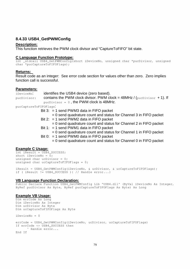
79
8.4.33 USB4_GetPWMConfig Description: This function retrieves the PWM clock divisor and “CaptureToFIFO” bit state. C Language Function Prototype: int _stdcall USB4_GetPWMConfig(short iDeviceNo, uns igned char *pucDivisor, unsigned char *pucCaptureToFIFOFlags);
Returns: Result code as an integer: See error code section for values other than zero. Zero implies function call is successful. Parameters: iDeviceNo : identifies the USB4 device (zero based). pucDivisor: contains the PWM clock divisor. PWM clock = 48MHz / (pucDivisor + 1). If
pucDivisor = 0 , the PWM clock is 48MHz. pucCaptureToFIFOFlags : Bit 3: = 1 send PWM3 data in FIFO packet = 0 send quadrature count and status for Channel 3 in FIFO packet Bit 2: = 1 send PWM2 data in FIFO packet = 0 send quadrature count and status for Channel 2 in FIFO packet Bit 1: = 1 send PWM1 data in FIFO packet = 0 send quadrature count and status for Channel 1 in FIFO packet Bit 0: = 1 send PWM0 data in FIFO packet = 0 send quadrature count and status for Channel 0 in FIFO packet
Example C Usage: int iResult = USB4_SUCCESS; short iDeviceNo = 0; unsigned char ucDivisor = 0; unsigned char ucCaptureToFIFOFlags = 0; iResult = USB4_GetPWMConfig(iDeviceNo, & ucDivisor, & ucCaptureToFIFOFlags); if ( iResult != USB4_SUCCESS ) // Handle error...
VB Language Function Declaration: Public Declare Function USB4_GetPWMConfig Lib "USB4 .dll" (ByVal iDeviceNo As Integer, ByRef pucDivisor As Byte, ByRef pucCaptureToFIFOFla gs As Byte) As Long
Example VB Usage: Dim errCode As Long Dim iDeviceNo As Integer Dim ucDivisor As Byte Dim ucCaptureToFIFOFlags As Byte iDeviceNo = 0 errCode = USB4_GetPWMConfig(iDeviceNo, ucDivisor, u cCaptureToFIFOFlags) If errCode <> USB4_SUCCESS then ‘ Handle error... End If
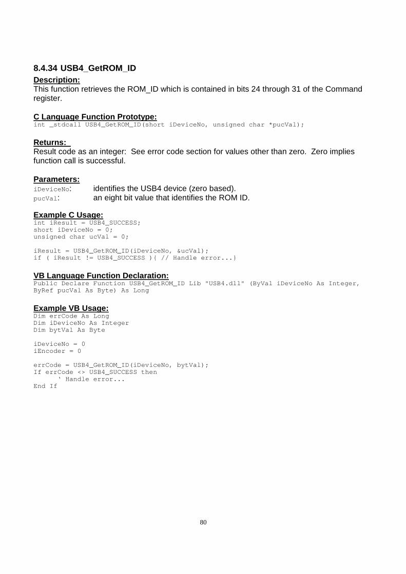
80
8.4.34 USB4_GetROM_ID Description: This function retrieves the ROM_ID which is contained in bits 24 through 31 of the Command register. C Language Function Prototype: int _stdcall USB4_GetROM_ID(short iDeviceNo, unsign ed char *pucVal);
Returns: Result code as an integer: See error code section for values other than zero. Zero implies function call is successful. Parameters: iDeviceNo : identifies the USB4 device (zero based). pucVal : an eight bit value that identifies the ROM ID.
Example C Usage: int iResult = USB4_SUCCESS; short iDeviceNo = 0; unsigned char ucVal = 0; iResult = USB4_GetROM_ID(iDeviceNo, &ucVal); if ( iResult != USB4_SUCCESS ) // Handle error...
VB Language Function Declaration: Public Declare Function USB4_GetROM_ID Lib "USB4.dl l" (ByVal iDeviceNo As Integer, ByRef pucVal As Byte) As Long
Example VB Usage: Dim errCode As Long Dim iDeviceNo As Integer Dim bytVal As Byte iDeviceNo = 0 iEncoder = 0 errCode = USB4_GetROM_ID(iDeviceNo, bytVal); If errCode <> USB4_SUCCESS then ‘ Handle error... End If
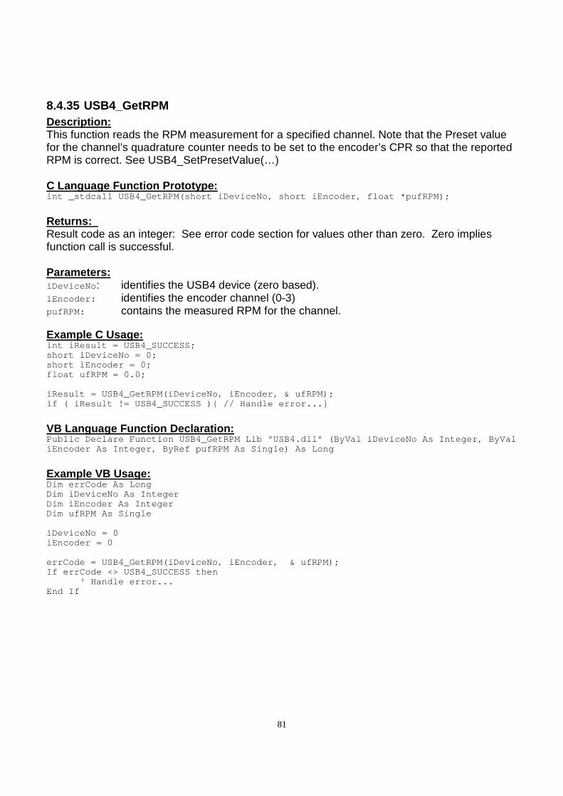
81
8.4.35 USB4_GetRPM Description: This function reads the RPM measurement for a specified channel. Note that the Preset value for the channel’s quadrature counter needs to be set to the encoder’s CPR so that the reported RPM is correct. See USB4_SetPresetValue(…) C Language Function Prototype: int _stdcall USB4_GetRPM(short iDeviceNo, short iEn coder, float *pufRPM);
Returns: Result code as an integer: See error code section for values other than zero. Zero implies function call is successful. Parameters: iDeviceNo : identifies the USB4 device (zero based). iEncoder: identifies the encoder channel (0-3) pufRPM: contains the measured RPM for the channel.
Example C Usage: int iResult = USB4_SUCCESS; short iDeviceNo = 0; short iEncoder = 0; float ufRPM = 0.0; iResult = USB4_GetRPM(iDeviceNo, iEncoder, & ufRPM) ; if ( iResult != USB4_SUCCESS ) // Handle error...
VB Language Function Declaration: Public Declare Function USB4_GetRPM Lib "USB4.dll" (ByVal iDeviceNo As Integer, ByVal iEncoder As Integer, ByRef pufRPM As Single) As Lon g
Example VB Usage: Dim errCode As Long Dim iDeviceNo As Integer Dim iEncoder As Integer Dim ufRPM As Single iDeviceNo = 0 iEncoder = 0 errCode = USB4_GetRPM(iDeviceNo, iEncoder, & ufRPM ); If errCode <> USB4_SUCCESS then ‘ Handle error... End If
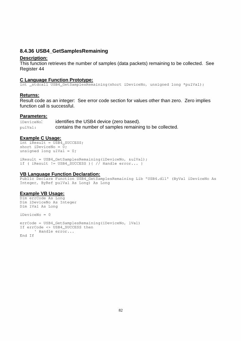
82
8.4.36 USB4_GetSamplesRemaining Description: This function retrieves the number of samples (data packets) remaining to be collected. See Register 44 C Language Function Prototype: int _stdcall USB4_GetSamplesRemaining(short iDevice No, unsigned long *pulVal);
Returns: Result code as an integer: See error code section for values other than zero. Zero implies function call is successful. Parameters: iDeviceNo : identifies the USB4 device (zero based). pulVal: contains the number of samples remaining to be collected. Example C Usage: int iResult = USB4_SUCCESS; short iDeviceNo = 0; unsigned long ulVal = 0; iResult = USB4_GetSamplesRemaining(iDeviceNo, &ulVa l); if ( iResult != USB4_SUCCESS ) // Handle error...
VB Language Function Declaration: Public Declare Function USB4_GetSamplesRemaining Li b "USB4.dll" (ByVal iDeviceNo As Integer, ByRef pulVal As Long) As Long
Example VB Usage: Dim errCode As Long Dim iDeviceNo As Integer Dim lVal As Long iDeviceNo = 0 errCode = USB4_GetSamplesRemaining(iDeviceNo, lVal) If errCode <> USB4_SUCCESS then ‘ Handle error... End If

83
8.4.37 USB4_GetSamplesToCollect Description: This function retrieves the number of samples to be collected when an acquisition is started. See Register 43. C Language Function Prototype: int _stdcall USB4_GetSamplesToCollect(short iDevice No, unsigned long *pulVal);
Returns: Result code as an integer: See error code section for values other than zero. Zero implies function call is successful. Parameters: iDeviceNo : identifies the USB4 device (zero based). pulVal: contains the number of samples to be collected.
Example C Usage: int iResult = USB4_SUCCESS; short iDeviceNo = 0; unsigned long ulVal = 0; iResult = USB4_GetSamplesToCollect(iDeviceNo, &ulVa l); if ( iResult != USB4_SUCCESS ) // Handle error...
VB Language Function Declaration: Public Declare Function USB4_GetSamplesToCollect Li b "USB4.dll" (ByVal iDeviceNo As Integer, ByRef pulVal As Long) As Long
Example VB Usage: Dim errCode As Long Dim iDeviceNo As Integer Dim lVal As Long iDeviceNo = 0 iEncoder = 0 errCode = USB4_GetSamplesToCollect(iDeviceNo, lVal) If errCode <> USB4_SUCCESS then ‘ Handle error... End If

84
8.4.38 USB4_GetSamplingRateCounter Description: This function retrieves the number of sample periods that have passed since the data acquisition was last started. C Language Function Prototype: int _stdcall USB4_GetSamplingRateCounter(short iDev iceNo, unsigned long *pulVal);
Returns: Result code as an integer: See error code section for values other than zero. Zero implies function call is successful. Parameters: iDeviceNo : identifies the USB4 device (zero based). pulval: contains the number of sample periods that have passed since the data
acquisition was last started. Example C Usage: int iResult = USB4_SUCCESS; short iDeviceNo = 0; unsigned long ulVal = 0; iResult = USB4_GetSamplingRateCounter(iDeviceNo, &u lVal); if ( iResult != USB4_SUCCESS ) // Handle error...
VB Language Function Declaration: Public Declare Function USB4_GetSamplingRateCounter Lib "USB4.dll" (ByVal iDeviceNo As Integer, ByRef pulVal As Long) As Long
Example VB Usage: Dim errCode As Long Dim iDeviceNo As Integer Dim lVal As Long iDeviceNo = 0 errCode = USB4_GetSamplingRateCounter(iDeviceNo, lV al) If errCode <> USB4_SUCCESS then ‘ Handle error... End If
85
8.4.39 USB4_GetSamplingRateMultiplier Description: This function retrieves the 32 bit sampling rate multiplier (N) which is used to determine the sampling period. The sampling period is calculated by the following equations. N: the value of the “sampling rate multiplier register” Sampling period = (N+1) * 2 microseconds. C Language Function Prototype: int _stdcall USB4_GetSamplingRateMultiplier(short i DeviceNo, unsigned long *pulVal);
Returns: Result code as an integer: See error code section for values other than zero. Zero implies function call is successful. Parameters: iDeviceNo : identifies the USB4 device (zero based). pulVal: contains the sampling rate multiplier used to calculate the sampling period. Example C Usage: int iResult = USB4_SUCCESS; short iDeviceNo = 0; unsigned long ulVal = 0; iResult = USB4_GetSamplingRateMultiplier(iDeviceNo, &ulVal); if ( iResult != USB4_SUCCESS ) // Handle error...
VB Language Function Declaration: Public Declare Function USB4_GetSamplingRateMultipl ier Lib "USB4.dll" (ByVal iDeviceNo As Integer, ByRef pulVal As Long) As Long
Example VB Usage: Dim errCode As Long Dim iDeviceNo As Integer Dim lVal As Long iDeviceNo = 0 errCode = USB4_GetSamplingRateMultiplier(iDeviceNo, lVal) If errCode <> USB4_SUCCESS then ‘ Handle error... End If
86
8.4.40 USB4_GetStatus Description: This function retrieves the Status register value for the specified encoder channel. See Section 6.1.1 Incremental Encoder Registers C Language Function Prototype: int _stdcall USB4_GetStatus(short iDeviceNo, short iEncoder, unsigned long *pulVal);
Returns: Result code as an integer: See error code section for values other than zero. Zero implies function call is successful. Parameters: iDeviceNo : identifies the USB4 device (zero based). iEncoder: identifies the encoder channel (zero based, 0-3). pulVal : contains the Status register value. Example C Usage: int iResult = USB4_SUCCESS; short iDeviceNo = 0; short iEncoder = 0; unsigned long ulVal = 0; iResult = USB4_GetStatus(iDeviceNo, iEncoder, &ulVa l); if ( iResult != USB4_SUCCESS ) // Handle error...
VB Language Function Declaration: Public Declare Function USB4_GetStatus Lib "USB4.dl l" (ByVal iDeviceNo As Integer, ByVal iEncoder As Integer, ByRef pulVal As Long) As Long
Example VB Usage: Dim errCode As Long Dim iDeviceNo As Integer Dim iEncoder As Integer Dim lVal As Long iDeviceNo = 0 iEncoder = 0 errCode = USB4_GetStatus(iDeviceNo, iEncoder, lVal) If errCode <> USB4_SUCCESS then ‘ Handle error... End If
87
8.4.41 USB4_GetStatusEx Description: This function retrieves the status of each trigger on event for the specified encoder channel. C Language Function Prototype: int _stdcall USB4_GetStatusEx(short iDeviceNo, shor t iEncoder, BOOL *pbDecreaseDetected, BOOL *pbIncreaseDetected, BOOL *pbIndexDetected, BOOL *pbRollunderDetected, BOOL *pbRolloverDetected, BOO L *pbMatchDetected, BOOL *pbZeroDetected);
Returns: Result code as an integer: See error code section for values other than zero. Zero implies function call is successful. Parameters: iDeviceNo : identifies the USB4 device (zero based). iEncoder: identifies the encoder channel (zero based, 0-3). pbDecreaseDetected : indicates if the encoder counter has decreased in value. pbIncreaseDetected : indicates if the encoder counter has increased in value. pbIndexDetected : indicates if an index signal has been detected. pbRollunderDetected : indicates if a roll under has occurred. pbRolloverDetected : indicates if a rollover has occurred. pbMatchDetected : indicates if a match has occurred. pbZeroDetected : indicates if the encoder counter was equal to zero. Example C Usage: int iResult = USB4_SUCCESS; short iDeviceNo = 0; Short iEncoder = 0; BOOL bDecreaseDetected = FALSE; BOOL bIncreaseDetected = FALSE; BOOL bIndexDetected = FALSE; BOOL bRollunderDetected = FALSE; BOOL bRolloverDetected = FALSE; BOOL bMatchDetected = FALSE; BOOL bZeroDetected = FALSE; iResult = USB4_GetStatusEx(iDeviceNo, iEncoder, &bD ecreaseDetected, &bIncreaseDetected, &bIndexDetected, &bRollunderDetected, &bRolloverDetected, &bMatchDetected, &bZeroDetected); if ( iResult != USB4_SUCCESS ) // Handle error...
88
VB Language Function Declaration: Public Declare Function USB4_GetStatusEx Lib "USB4. dll" (ByVal iDeviceNo As Integer, ByVal iEncoder As Integer, ByRef pbDecreaseDetected As Long, ByRef pbIncreaseDetected As Long, ByRef pbIndexDetected As Long, ByRef pbRol lunderDetected As Long, ByRef pbRolloverDetected As Long, ByRef pbMatchDetected A s Long, ByRef pbZeroDetected As Long) As Long
Example VB Usage: Dim errCode As Long Dim iDeviceNo As Integer Dim iEncoder As Integer Dim bDecreaseDetected As Long Dim bIncreaseDetected As Long Dim bIndexDetected As Long Dim bRollunderDetected As Long Dim bRolloverDetected As Long Dim bMatchDetected As Long Dim bZeroDetected As Long iDeviceNo = 0 iEncoder = 0 errCode = USB4_GetStatusEx(iDeviceNo, iEncoder, bDe creaseDetected, bIncreaseDetected, bIndexDetected, bRollunderDetected, bRolloverDetected, bMatchDetected, bZeroDetected) If errCode <> USB4_SUCCESS then ‘ Handle error… End If
89
8.4.42 USB4_GetTimeBasedLogSettings Description: This function gets the trigger settings for time-based data acquisition. C Language Function Prototype: int _stdcall USB4_GetTimeBasedLogSettings(short iDe viceNo, unsigned char * pucInputTrigger1, unsigned char * ucInputTrig1And, unsigned char * pucInputTrigger2, unsigned char * ucInputTrig2And, unsigned char * pucADCTrigger, unsigned short * pu iADCThreshold, unsigned char * pucPWMTrigger, unsigned short * pu iPWMThreshold, unsigned char * ucEncoderChannels, unsigned long * ulNumberOfSamples
Returns: Result code as an integer: See error code section for values other than zero. Zero implies function call is successful. Parameters: iDeviceNo : identifies the USB4 device (zero based). pucInputTrigger1 : 8 byte array of trigger1 codes for each input bit (see table below) ucInputTrig1And : determines if the array of trigger1 conditions for each input bit are AND’ed
or OR’ed together to form the final state of Trigger1. 1: AND, 0: OR. pucInputTrigger2 : 8 byte array of trigger2 codes for each input bit (see table below) ucInputTrig2And : determines if the array of trigger2 conditions for each input bit are AND’ed
or OR’ed together to form the final state of Trigger2. 1: AND, 0: OR. pucADCTrigger : 4 byte array of ADC trigger condition for each input channel.
0: Ignore, 1: trigger if reading > ADC threshold, 2: trigger if reading <= ADC threshold
puiADCThreshold : 4 byte array of trigger thresholds (0 to 4095) for each ADC channel pucPWMTrigger : 4 byte array of pulse width trigger condition for each input channel.
0: Ignore, 1: trigger if reading > pulse width threshold, 2: trigger if reading <= pulse width threshold
puiPWMThreshold : 4 byte array of pulse width thresholds (0 to 65535) for each PWM channel. The least significant 16-bits of the 32-bit pulse width measurement is used. The user must make sure the pulse width count does not exceed 16-bits.
ucEncoderChannels : the lowest 4 bits of this parameter determine if an encoder channel event will start a time-based data acquisition. Bit 0 is for channel 0 and bit 1 for
channel 1 and so on. 0: disable, 1: enable ulNumberOfSamples : identifies the number of data packets to be collected.
Triggering / Qualifier Codes Trigger or qualify never (ignore) 0 Trigger or qualify on rising edge 1 Trigger or qualify on falling edge 2 Trigger or qualify on either edge 3 Trigger or qualify on high condition 4 Trigger or qualify on low condition 5
90
Trigger or qualify unconditionally (always) 6 Trigger or qualify unconditionally (always) 7
Example C Usage: int iResult = USB4_SUCCESS; short iDeviceNo = 0; unsigned char ucTrigger1[8]; unsigned char ucTrigger1And; unsigned char ucTrigger2[8]; unsigned char ucTrigger2And; unsigned char ucADCTrigger[4]; unsigned short uiADCThreshold[4]; unsigned char ucPWMTrigger[4]; unsigned short uiPWMThreshold[4]; unsigned char ucEncoderChannels; unsigned long ulNumberOfSamples; iResult = USB4_GetTimeBasedLogSettings(iDeviceNo, u cTrigger1, &ucTrigger1And, ucTrigger2, &ucTrigger2And, ucADCTrigger, uiADCThre shold, ucPWMTrigger, uiPWMThreshold, &ucEncoderChannels, &ulNumberOfSamp les); if ( iResult != USB4_SUCCESS ) // Handle error...
VB Language Function Declaration: Public Declare Function USB4_GetTimeBasedLogSetting s Lib "USB4.dll" ( ByVal iDeviceNo As Integer, ByRef pbytTrigger1 As Byte, ByRef bytTrig1And As By te, ByRef pbytTrigger2 As Byte, ByRef bytTrig2And As By te, ByRef ucADCTrigger As Byte, ByRef uiADCThreshold As Integer, ByRef ucPWMTrigger As Byte, ByRef uiPWMThreshold As Integer, ByRef bytEncoderChannels As Byte, ByRef ulNumberOfSamples As Long) As Long
Example VB Usage: Dim errCode As Long Dim iDeviceNo As Integer Dim bytTrigger1(7) As Byte Dim bytTrigger1And As Byte Dim bytTrigger2(7) As Byte Dim bytTrigger2And As Byte Dim bytADCTrigger(3) As Byte Dim uiADCThreshold(3) As Integer Dim bytPWMTrigger(3) As Byte Dim uiPWMThreshold(3) As Integer Dim bytEncoderChannels As Byte Dim lNumberOfSamples As Long iDeviceNo = 0 errCode = USB4_GetTimeBasedLogSettings(iDeviceNo, b ytTrigger1(0), bytTrigger1And, bytTrigger2(0), bytTrigger2And, bytADCTrigger(0), u iADCThreshold(0), bytPWMTrigger(0), uiPWMThreshold(0), bytEncoderChan nels, lNumberOfSamples) If errCode <> USB4_SUCCESS then ‘ Handle error... End If
91
8.4.43 USB4_GetTimeStamp Description: This function writes to the Register 7:bit 5 which causes the Timestamp counter to be latched to the Timestamp Latch and then reads the Timestamp Latch. Refer to the USB4_ReadTimeStamp function to simply read the Timestamp Latch without causing the Timestamp counter to be transferred to the Timestamp Latch. C Language Function Prototype: int _stdcall USB4_GetTimeStamp(short iDeviceNo, uns igned long *pulVal);
Returns: Result code as an integer: See error code section for values other than zero. Zero implies function call is successful. Parameters: iDeviceNo : identifies the USB4 device (zero based). pulVal : contains the Timestamp Latch value. Example C Usage: int iResult = USB4_SUCCESS; short iDeviceNo = 0; unsigned long ulVal = 0; iResult = USB4_GetTimeStamp(iDeviceNo, &ulVal); if ( iResult != USB4_SUCCESS ) // Handle error...
VB Language Function Declaration: Public Declare Function USB4_GetTimeStamp Lib "USB4 .dll" (ByVal iDeviceNo As Integer, ByRef pulVal As Long) As Long
Example VB Usage: Dim errCode As Long Dim iDeviceNo As Integer Dim lVal As Long iDeviceNo = 0 errCode = USB4_GetTimeStamp(iDeviceNo, lVal) If errCode <> USB4_SUCCESS then ‘ Handle error… End If

92
8.4.44 USB4_GetTriggerOnDecrease Description: This function retrieves a boolean value that indicates whether a trigger signal is generated when the count decreases for the specified encoder channel C Language Function Prototype: int _stdcall USB4_GetTriggerOnDecrease(short iDevic eNo, short iEncoder, BOOL *pbVal); Returns: Result code as an integer: See error code section for values other than zero. Zero implies function call is successful. Parameters: iDeviceNo : identifies the USB4 device (zero based). iEncoder: identifies the encoder channel (zero based, 0-3). pbVal : TRUE = enable trigger generation when counter decreases. FALSE = disable trigger generation when counter decreases. Example C Usage: int iResult = USB4_SUCCESS; short iDeviceNo = 0; short iEncoder = 0; BOOL bVal = False; iResult = USB4_GetTriggerOnDecrease(iDeviceNo, iEnc oder, &bVal); if ( iResult != USB4_SUCCESS ) // Handle error...
VB Language Function Declaration: Public Declare Function USB4_GetTriggerOnDecrease L ib "USB4.dll" (ByVal iDeviceNo As Integer, ByVal iEncoder As Integer, ByRef pbVal As Long) As Long
Example VB Usage: Dim errCode As Long Dim iDeviceNo As Integer Dim iEncoder As Integer Dim bVal As Long iDeviceNo = 0 iEncoder = 0 errCode = USB4_GetTriggerOnDecrease(iDeviceNo, iEnc oder, bVal) If errCode <> USB4_SUCCESS then ‘ Handle error… End If
93
8.4.45 USB4_GetTriggerOnIncrease Description: This function retrieves a boolean value that indicates whether a trigger signal is generated when the count increases for the specified encoder channel C Language Function Prototype: int _stdcall USB4_GetTriggerOnIncrease(short iDevic eNo, short iEncoder, BOOL *pbVal);
Returns: Result code as an integer: See error code section for values other than zero. Zero implies function call is successful. Parameters: iDeviceNo : identifies the USB4 device (zero based). iEncoder: identifies the encoder channel (zero based, 0-3). pbVal : TRUE = enable trigger generation when counter increases. FALSE = disable trigger generation when counter increases. Example C Usage: int iResult = USB4_SUCCESS; short iDeviceNo = 0; short iEncoder = 0; BOOL bVal = False; iResult = USB4_GetTriggerOnIncrease(iDeviceNo, iEnc oder, &bVal); if ( iResult != USB4_SUCCESS ) // Handle error...
VB Language Function Declaration: Public Declare Function USB4_GetTriggerOnIncrease L ib "USB4.dll" (ByVal iDeviceNo As Integer, ByVal iEncoder As Integer, ByRef pbVal As Long) As Long
Example VB Usage: Dim errCode As Long Dim iDeviceNo As Integer Dim iEncoder As Integer Dim bVal As Long iDeviceNo = 0 iEncoder = 0 errCode = USB4_GetTriggerOnIncrease(iDeviceNo, iEnc oder, bVal) If errCode <> USB4_SUCCESS then ‘ Handle error… End If
94
8.4.46 USB4_GetTriggerOnIndex Description: This function retrieves a boolean value that indicates whether a trigger signal is generated when the specified encoder counter detects an index pulse. C Language Function Prototype: int _stdcall USB4_GetTriggerOnIndex(short iDeviceNo , short iEncoder, BOOL *pbVal);
Returns: Result code as an integer: See error code section for values other than zero. Zero implies function call is successful. Parameters: iDeviceNo : identifies the USB4 device (zero based). iEncoder: identifies the encoder channel (zero based, 0-3). pbVal : TRUE = enable trigger generation when index pulse detected. FALSE = disable trigger generation when index pulse detected.
Example C Usage: int iResult = USB4_SUCCESS; short iDeviceNo = 0; short iEncoder = 0; BOOL bVal = False; iResult = USB4_GetTriggerOnIndex(iDeviceNo, iEncode r, &bVal); if ( iResult != USB4_SUCCESS ) // Handle error...
VB Language Function Declaration: Public Declare Function USB4_GetTriggerOnIndex Lib "USB4.dll" (ByVal iDeviceNo As Integer, ByVal iEncoder As Integer, ByRef pbVal As Long) As Long
Example VB Usage: Dim errCode As Long Dim iDeviceNo As Integer Dim iEncoder As Integer Dim bVal As Long iDeviceNo = 0 iEncoder = 0 errCode = USB4_GetTriggerOnIndex(iDeviceNo, iEncode r, bVal) If errCode <> USB4_SUCCESS then ‘ Handle error… End If
95
8.4.47 USB4_GetTriggerOnMatch Description: This function retrieves a boolean value that indicates whether a trigger signal is generated when the specified encoder counter value equals the corresponding Match register value. C Language Function Prototype: int _stdcall USB4_GetTriggerOnMatch(short iDeviceNo , short iEncoder, BOOL *pbVal); Returns: Result code as an integer: See error code section for values other than zero. Zero implies function call is successful. Parameters: iDeviceNo : identifies the USB4 device (zero based). iEncoder: identifies the encoder channel (zero based, 0-3). pbVal : TRUE = enable trigger generation when match detected. FALSE = disable trigger generation when match detected. Example C Usage: int iResult = USB4_SUCCESS; short iDeviceNo = 0; short iEncoder = 0; BOOL bVal = FALSE; iResult = USB4_GetTriggerOnMatch(iDeviceNo, iEncode r, &bVal); if ( iResult != USB4_SUCCESS ) // Handle error...
VB Language Function Declaration: Public Declare Function USB4_GetTriggerOnMatch Lib "USB4.dll" (ByVal iDeviceNo As Integer, ByVal iEncoder As Integer, ByRef pbVal As Long) As Long
Example VB Usage: Dim errCode As Long Dim iDeviceNo As Integer Dim iEncoder As Integer Dim bVal As Long iDeviceNo = 0 iEncoder = 0 errCode = USB4_GetTriggerOnMatch(iDeviceNo, iEncode r, bVal) If errCode <> USB4_SUCCESS then ‘ Handle error… End If
96
8.4.48 USB4_GetTriggerOnRollover Description: This function retrieves a boolean value that indicates whether a trigger signal is generated when the specified encoder counter rolls over from N-1 to 0 in modulo-N mode. C Language Function Prototype: int _stdcall USB4_GetTriggerOnRollover(short iDevic eNo, short iEncoder, BOOL *pbVal); Returns: Result code as an integer: See error code section for values other than zero. Zero implies function call is successful. Parameters: iDeviceNo : identifies the USB4 device (zero based). iEncoder: identifies the encoder channel (zero based, 0-3). pbVal : TRUE = enable trigger generation when rollover detected. FALSE = disable trigger generation when rollover detected. Example C Usage: int iResult = USB4_SUCCESS; short iDeviceNo = 0; short iEncoder = 0; BOOL bVal = False; iResult = USB4_GetTriggerOnRollover(iDeviceNo, iEnc oder, &bVal); if ( iResult != USB4_SUCCESS ) // Handle error...
VB Language Function Declaration: Public Declare Function USB4_GetTriggerOnRollover L ib "USB4.dll" (ByVal iDeviceNo As Integer, ByVal iEncoder As Integer, ByRef pbVal As Long) As Long
Example VB Usage: Dim errCode As Long Dim iDeviceNo As Integer Dim iEncoder As Integer Dim bVal As Long iDeviceNo = 0 iEncoder = 0 errCode = USB4_GetTriggerOnRollover(iDeviceNo, iEnc oder, bVal) If errCode <> USB4_SUCCESS then ‘ Handle error… End If
97
8.4.49 USB4_GetTriggerOnRollunder Description: This function retrieves a boolean value that indicates whether a trigger signal is generated when the specified encoder counter rolls under from 0 to N-1 in modulo-N mode. C Language Function Prototype: int _stdcall USB4_GetTriggerOnRollunder(short iDevi ceNo, short iEncoder, BOOL *pbVal);
Returns: Result code as an integer: See error code section for values other than zero. Zero implies function call is successful. Parameters: iDeviceNo : identifies the USB4 device (zero based). iEncoder: identifies the encoder channel (zero based, 0-3). pbVal : TRUE = enable trigger generation when rollunder detected. FALSE = disable trigger generation when rollunder detected. Example C Usage: int iResult = USB4_SUCCESS; short iDeviceNo = 0; short iEncoder = 0; BOOL bVal = False; iResult = USB4_GetTriggerOnRollunder(iDeviceNo, iEn coder, &bVal); if ( iResult != USB4_SUCCESS ) // Handle error...
VB Language Function Declaration: Public Declare Function USB4_GetTriggerOnRollunder Lib "USB4.dll" (ByVal iDeviceNo As Integer, ByVal iEncoder As Integer, ByRef pbVal As Long) As Long
Example VB Usage: Dim errCode As Long Dim iDeviceNo As Integer Dim iEncoder As Integer Dim bVal As Long iDeviceNo = 0 iEncoder = 0 errCode = USB4_GetTriggerOnRollunder(iDeviceNo, iEn coder, bVal) If errCode <> USB4_SUCCESS then ‘ Handle error… End If
98
8.4.50 USB4_GetTriggerOnZero Description: This function retrieves a boolean value that indicates whether a trigger signal is generated when the specified encoder counter value = 0. C Language Function Prototype: int _stdcall USB4_GetTriggerOnZero(short iDeviceNo, short iEncoder, BOOL *pbVal);
Returns: Result code as an integer: See error code section for values other than zero. Zero implies function call is successful. Parameters: iDeviceNo : identifies the USB4 device (zero based). iEncoder: identifies the encoder channel (zero based, 0-3). bVal : TRUE = enable trigger generation when encoder counter = 0. FALSE = disable trigger generation when encoder counter = 0. Example C Usage: int iResult = USB4_SUCCESS; short iDeviceNo = 0; short iEncoder = 0; BOOL bVal = False; iResult = USB4_GetTriggerOnZero(iDeviceNo, iEncoder , &bVal); if ( iResult != USB4_SUCCESS ) // Handle error...
VB Language Function Declaration: Public Declare Function USB4_GetTriggerOnZero Lib " USB4.dll" (ByVal iDeviceNo As Integer, ByVal iEncoder As Integer, ByRef pbVal As Long) As Long
Example VB Usage: Dim errCode As Long Dim iDeviceNo As Integer Dim iEncoder As Integer Dim bVal As Long iDeviceNo = 0 iEncoder = 0 errCode = USB4_GetTriggerOnZero(iDeviceNo, iEncoder , bVal) If errCode <> USB4_SUCCESS then ‘ Handle error… End If
99
8.4.51 USB4_GetVersion
Description: This function retrieves the version number associated with a specified device. C Language Function Prototype: int _stdcall USB4_GetVersion(short iDeviceNo, unsig ned short *pusVersion);
Returns: Result code as an integer: See error code section for values other than zero. Zero implies function call is successful. Parameters: iDeviceNo : identifies the USB4 device (zero based). pusVersion: contains the version number of the USB4 device (zero based). Example C Usage: int iResult = USB4_SUCCESS; short iDeviceNo = 0; unsigned short usVersion = 0; iResult = USB4_GetVersion(iDeviceNo, & usVersion); if ( iResult != USB4_SUCCESS ) // Handle error...
VB Language Function Declaration: Public Declare Function USB4_GetVersion Lib "USB4.d ll" (ByVal iDeviceNo As Integer, ByRef pusVersion As Integer) As Long
Example VB Usage: Dim errCode As Long Dim iDeviceNo As Integer Dim usVersion As Integer iDeviceNo = 0 errCode = USB4_GetVersion(iDeviceNo, usVersion) If errCode <> USB4_SUCCESS then ‘ Handle error... End If
100
8.4.52 USB4_Initialize Description: This function is used to open a connection with all installed and detected USB4 encoder interface devices. This function returns the number of devices detected in the in/out parameter piDeviceCount. This function must be called before any other function. Almost all other function calls require a device number. If there are two boards detected, then the first board will be device number 0 and the second device number 1. During initialization, a device’s module address is read and compared to previously read module addresses. If the module address already exists, then the newly read device’s module address is assigned the next available module address. If the USB4’s FPGA code is not running, then it is downloaded and executed and the previously saved encoder control parameters are restored. After USB4_Initialize is called, DLL functions can be used to change the configuration if needed. C Language Function Prototype: int _stdcall USB4_Initialize(short *piDeviceCount);
Returns: Result code as an integer: See error code section for values other than zero. Zero implies function call is successful. Parameters: piDeviceCount : an in/out parameter used to return the number of boards detected. Example C Usage: int iResult = 0; short iDeviceCount = 0; iResult = USB4_Initialize(&iDeviceCount); if ( iResult != USB4_SUCCESS ) // Handle error...
VB Language Function Declaration: Public Declare Function USB4_Initialize Lib "USB4.d ll" (ByRef piDeviceCount As Integer) As Long
Example VB Usage: Dim errCode As Long Dim iDeviceCount As Integer errCode = USB4_Initialize(iDeviceCount) If errCode <> USB4_SUCCESS then ‘ Handle error... End If
101
8.4.53 USB4_IsFIFOBufferEmpty Description: This function reads the FIFO status control register (Register 38) and determines if the FIFO is empty by examining bit 9. Bit 9 = 1 implies that the FIFO is empty and the function will return TRUE (1), otherwise the function returns FALSE(0). C Language Function Prototype: BOOL _stdcall USB4_IsFIFOBufferEmpty(short iDeviceN o, int *piResult);
Returns: TRUE (1) if the FIFO buffer is empty, otherwise FALSE (0). Parameters: iDeviceNo : identifies the USB4 device (zero based). piResult : Result code as an integer: See error code section for values other than zero.
Zero implies function call is successful. Example C Usage: int iResult = USB4_SUCCESS; short iDeviceNo = 0; BOOL bFIFOEmpty = FALSE; bFIFOEmpty = USB4_IsFIFOBufferEmpty(iDeviceNo, &iRe sult); if ( iResult != USB4_SUCCESS ) // Handle error...
VB Language Function Declaration: Public Declare Function USB4_IsFIFOBufferEmpty Lib "USB4.dll" (ByVal iDeviceNo As Integer, ByRef iResult As Long) As Long
Example VB Usage: Dim iResult As Long Dim iDeviceNo As Integer Dim bFIFOEmpty As Long iDeviceNo = 0 bFIFOEmpty = USB4_IsFIFOBufferEmpty(iDeviceNo, iRes ult) If iResult <> 0 then ‘ Handle error... End If
102
8.4.54 USB4_IsFIFOBufferFull Description: This function reads the FIFO status control register (Register 38) and determines if the FIFO is empty by examining bit 8. Bit 8 = 1 implies that the FIFO is full and the function will return TRUE (1), otherwise the function returns FALSE(0). Note: If the FIFO buffer becomes full during a Time-Based or Event-Based data acquisition, no other records will be written to the FIFO buffer until records have been read from the FIFO buffer to free space or the FIFO buffer is cleared. During an Event-Based data acquisition, the event that triggered the FIFO buffer full status must be cleared before that event can capture another event. C Language Function Prototype: BOOL _stdcall USB4_IsFIFOBufferFull(short iDeviceNo , int *piResult);
Returns: TRUE (1) if the FIFO buffer is full, otherwise FALSE (0). Parameters: iDeviceNo : identifies the USB4 device (zero based). piResult : Result code as an integer: See error code section for values other than zero.
Zero implies function call is successful. Example C Usage: int iResult = USB4_SUCCESS; short iDeviceNo = 0; BOOL bFIFOFull = FALSE; bFIFOFull = USB4_IsFIFOBufferFull(iDeviceNo, &iResu lt); if ( iResult != USB4_SUCCESS ) // Handle error...
VB Language Function Declaration: Public Declare Function USB4_IsFIFOBufferFull Lib " USB4.dll" (ByVal iDeviceNo As Integer, ByRef iResult As Long) As Long
Example VB Usage: Dim iResult As Long Dim iDeviceNo As Integer Dim bFIFOFull As Long iDeviceNo = 0 bFIFOFull = USB4_IsFIFOBufferFull(iDeviceNo, iResul t) If iResult <> 0 then ‘ Handle error... End If
103
8.4.55 USB4_PresetCount Description: This function sets the specified channel’s counter to its Preset value. C Language Function Prototype: int _stdcall USB4_PresetCount(short iDeviceNo, shor t iEncoder);
Returns: Result code as an integer: See error code section for values other than zero. Zero implies function call is successful. Parameters: iDeviceNo : identifies the USB4 device (zero based). iEncoder: identifies the encoder channel (zero based, 0-3). Example C Usage: int iResult = USB4_SUCCESS; short iDeviceNo = 0; short iEncoder = 0; iResult = USB4_PresetCount(iDeviceNo, iEncoder); if ( iResult != USB4_SUCCESS ) // Handle error...
VB Language Function Declaration: Public Declare Function USB4_PresetCount Lib "USB4. dll" (ByVal iDeviceNo As Integer, ByVal iEncoder As Integer) As Long
Example VB Usage: Dim errCode As Long Dim iDeviceNo As Integer Dim iEncoder As Integer iDeviceNo = 0 iEncoder = 0 errCode = USB4_PresetCount(iDeviceNo, iEncoder) If errCode <> USB4_SUCCESS then ‘ Handle error... End If
104
8.4.56 USB4_ReadFIFOBuffer Description: This function reads data records from the FIFO buffer and copies the data into user allocated arrays. The user is responsible for creating the arrays and passing their pointer to this function. The plSize parameter identifies the number of records to read. Each of the allocated arrays must be at least plSize in length. If the specified number of records is greater than the number of records in the FIFO buffer, then only the records in the FIFO buffer are read and copied. The plSize parameter will be changed to the number of records that were copied. This function returns when : (a) the number of records read equals plSize or (b) the FIFO buffer is empty or (c) the timeout interval specified by ulReadTimeout has expired C Language Function Prototype: int _stdcall USB4_ReadFIFOBuffer(short iDeviceNo, long *plSize, unsigned long * pTime, unsigned long * pCount0, unsigned long * pCount1, unsigned long * pCount2, unsigned long * pCount3, unsigned char * pStatus0, unsigned char * pStatus1, unsigned char * pStatus2, unsigned char * pStatus3, unsigned char * pInput, unsigned char * pEStop, unsigned long * pADC0, unsigned long * pADC1, unsigned long * pADC2, unsigned long * pADC3 unsigned long ulReadTimeout);
Returns: Result code as an integer: See error code section for values other than zero. Zero implies function call is successful. Parameters: iDeviceNo : identifies the USB4 device (zero based). plSize : refer to description above. pTime : an array of Timestamps. pCount0 : an array of encoder channel 0 counts. (or lower 16-bits of PWM period + lower
16-bits of PWM ontime concatenated as a 32-bit word) pCount1 : an array of encoder channel 1 counts. (or lower 16-bits of PWM period + lower
16-bits of PWM ontime concatenated as a 32-bit word) pCount2 : an array of encoder channel 2 counts. (or lower 16-bits of PWM period + lower
16-bits of PWM ontime concatenated as a 32-bit word)
105
pCount3 : an array of encoder channel 3 counts. (or lower 16-bits of PWM period + lower 16-bits of PWM ontime concatenated as a 32-bit word)
pStatus0 : an array of encoder channel 0 status codes. pStatus1 : an array of encoder channel 1 status codes. pStatus2 : an array of encoder channel 2 status codes. pStatus3 : an array of encoder channel 3 status codes. Bit 7: last direction------------------------from bit 23 of Status reg. Bit 6: latched_retard_detected-----------from bit 13 of Status reg. Bit 5: latched_advance_detected--------from bit 12 of Status reg. Bit 4: latched_index_detected-----------from bit 11 of Status reg. Bit 3: latched_borrow_detected---------from bit 10 of Status reg. Bit 2: latched_carry_detected------------from bit 9 of Status reg. Bit 1: latched_match_detected-----------from bit 8 of Status reg. Bit 0: latched_zero_detected-------------from bit 7 of Status reg. pInput : a byte containing the input port register data. pEStop : a byte containing the latched E-stop status. pADC0: an unsigned long containing the analog to digital value of AD channel 0. pADC1: an unsigned long containing the analog to digital value of AD channel 1. pADC2: an unsigned long containing the analog to digital value of AD channel 2. pADC3: an unsigned long containing the analog to digital value of AD channel 3. ulReadTimeout : read timeout interval in milliseconds Example C Usage: int iResult = USB4_SUCCESS; short iDeviceNo = 0; #DEFINE MY_BUFF_SIZE = 10000 long lSize = MY_BUFF_SIZE; unsigned long Time[MY_BUFF_SIZE]; unsigned long Count0[MY_BUFF_SIZE]; unsigned long Count1[MY_BUFF_SIZE]; unsigned long Count2[MY_BUFF_SIZE]; unsigned long Count3[MY_BUFF_SIZE]; unsigned char Status0[MY_BUFF_SIZE]; unsigned char Status1[MY_BUFF_SIZE]; unsigned char Status2[MY_BUFF_SIZE]; unsigned char Status3[MY_BUFF_SIZE]; unsigned char Input[MY_BUFF_SIZE]; unsigned char EStop[MY_BUFF_SIZE]; unsigned long ADC0[MY_BUFF_SIZE]; unsigned long ADC1[MY_BUFF_SIZE]; unsigned long ADC2[MY_BUFF_SIZE]; unsigned long ADC3[MY_BUFF_SIZE]; unsigned long ulReadTimeout = 2000; iResult = USB4_ReadFIFOBuffer(iDeviceNo, &lSize, Ti me, Count0, Count1, Count2, Count3, Status0, Status1, Status2, Status3, Input, EStop, ADC0, ADC1, ADC2, ADC3, ulRead Timeout); if ( iResult != USB4_SUCCESS ) // Handle error...
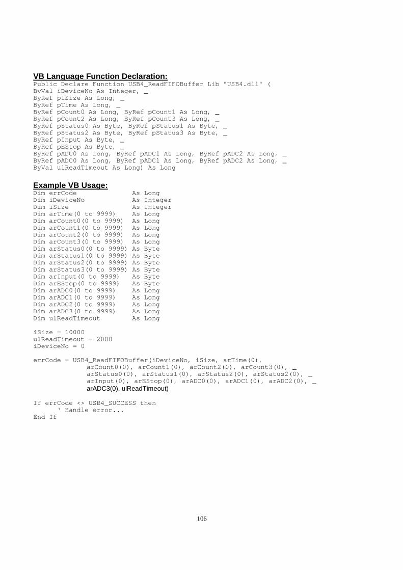
106
VB Language Function Declaration: Public Declare Function USB4_ReadFIFOBuffer Lib "US B4.dll" ( ByVal iDeviceNo As Integer, _ ByRef plSize As Long, _ ByRef pTime As Long, _ ByRef pCount0 As Long, ByRef pCount1 As Long, _ ByRef pCount2 As Long, ByRef pCount3 As Long, _ ByRef pStatus0 As Byte, ByRef pStatus1 As Byte, _ ByRef pStatus2 As Byte, ByRef pStatus3 As Byte, _ ByRef pInput As Byte, _ ByRef pEStop As Byte, _ ByRef pADC0 As Long, ByRef pADC1 As Long, ByRef pAD C2 As Long, _ ByRef pADC0 As Long, ByRef pADC1 As Long, ByRef pAD C2 As Long, _ ByVal ulReadTimeout As Long) As Long
Example VB Usage: Dim errCode As Long Dim iDeviceNo As Integer Dim iSize As Integer Dim arTime(0 to 9999) As Long Dim arCount0(0 to 9999) As Long Dim arCount1(0 to 9999) As Long Dim arCount2(0 to 9999) As Long Dim arCount3(0 to 9999) As Long Dim arStatus0(0 to 9999) As Byte Dim arStatus1(0 to 9999) As Byte Dim arStatus2(0 to 9999) As Byte Dim arStatus3(0 to 9999) As Byte Dim arInput(0 to 9999) As Byte Dim arEStop(0 to 9999) As Byte Dim arADC0(0 to 9999) As Long Dim arADC1(0 to 9999) As Long Dim arADC2(0 to 9999) As Long Dim arADC3(0 to 9999) As Long Dim ulReadTimeout As Long iSize = 10000 ulReadTimeout = 2000 iDeviceNo = 0 errCode = USB4_ReadFIFOBuffer(iDeviceNo, iSize, arT ime(0), arCount0(0), arCount1(0), arCount2(0), arCount3(0) , _ arStatus0(0), arStatus1(0), arStatus2(0), arStatus 2(0), _ arInput(0), arEStop(0), arADC0(0), arADC1(0), arAD C2(0), _ arADC3(0), ulReadTimeout) If errCode <> USB4_SUCCESS then ‘ Handle error... End If
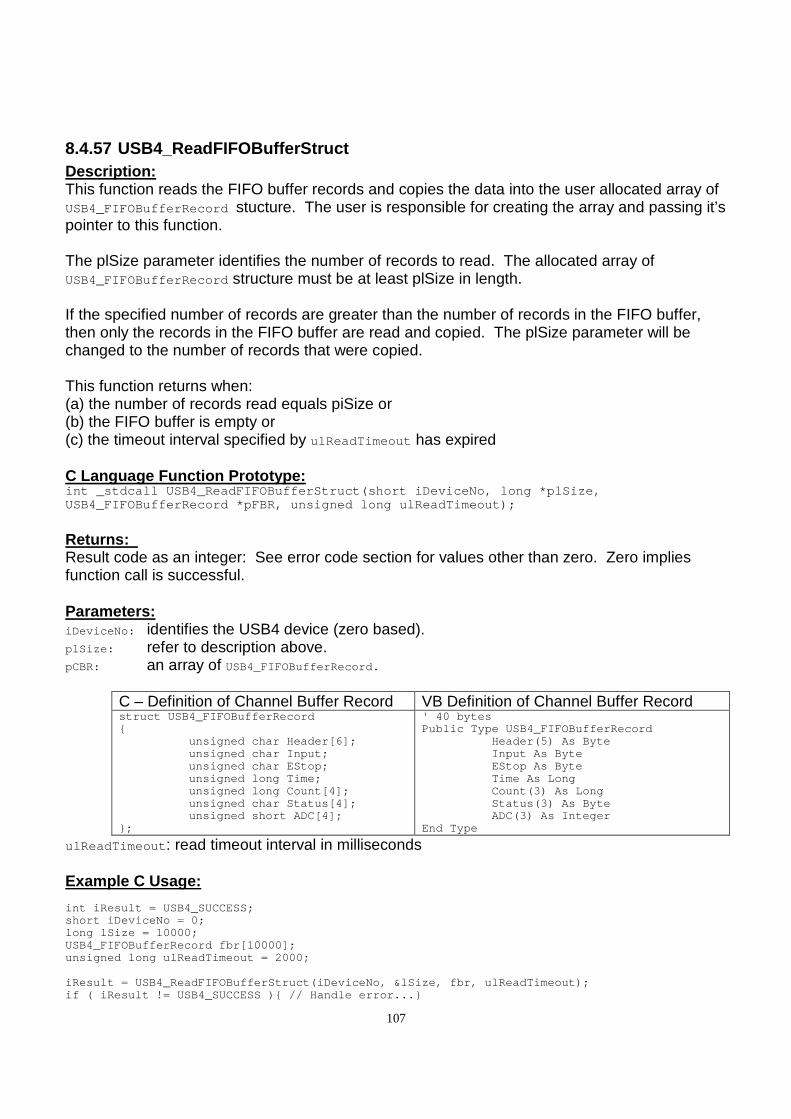
107
8.4.57 USB4_ReadFIFOBufferStruct Description: This function reads the FIFO buffer records and copies the data into the user allocated array of USB4_FIFOBufferRecord stucture. The user is responsible for creating the array and passing it’s pointer to this function. The plSize parameter identifies the number of records to read. The allocated array of USB4_FIFOBufferRecord structure must be at least plSize in length. If the specified number of records are greater than the number of records in the FIFO buffer, then only the records in the FIFO buffer are read and copied. The plSize parameter will be changed to the number of records that were copied. This function returns when: (a) the number of records read equals piSize or (b) the FIFO buffer is empty or (c) the timeout interval specified by ulReadTimeout has expired C Language Function Prototype: int _stdcall USB4_ReadFIFOBufferStruct(short iDevic eNo, long *plSize, USB4_FIFOBufferRecord *pFBR, unsigned long ulReadTi meout);
Returns: Result code as an integer: See error code section for values other than zero. Zero implies function call is successful. Parameters: iDeviceNo: identifies the USB4 device (zero based). plSize: refer to description above. pCBR: an array of USB4_FIFOBufferRecord.
C – Definition of Channel Buffer Record VB Definition of Channel Buffer Record struct USB4_FIFOBufferRecord unsigned char Header[6]; unsigned char Input; unsigned char EStop; unsigned long Time; unsigned long Count[4]; unsigned char Status[4]; unsigned short ADC[4]; ;
' 40 bytes Public Type USB4_FIFOBufferRecord Header(5) As Byte Input As Byte EStop As Byte Time As Long Count(3) As Long Status(3) As Byte ADC(3) As Integer End Type
ulReadTimeout : read timeout interval in milliseconds Example C Usage: int iResult = USB4_SUCCESS; short iDeviceNo = 0; long lSize = 10000; USB4_FIFOBufferRecord fbr[10000]; unsigned long ulReadTimeout = 2000; iResult = USB4_ReadFIFOBufferStruct(iDeviceNo, &lSi ze, fbr, ulReadTimeout); if ( iResult != USB4_SUCCESS ) // Handle error...
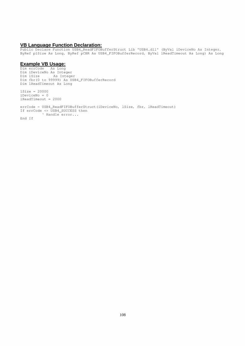
108
VB Language Function Declaration: Public Declare Function USB4_ReadFIFOBufferStruct L ib "USB4.dll" (ByVal iDeviceNo As Integer, ByRef plSize As Long, ByRef pCBR As USB4_FIFOBuffer Record, ByVal lReadTimeout As Long) As Long
Example VB Usage: Dim errCode As Long Dim iDeviceNo As Integer Dim lSize As Integer Dim fbr(0 to 99999) As USB4_FIFOBufferRecord Dim lReadTimeout As Long lSize = 20000 iDeviceNo = 0 lReadTimeout = 2000 errCode = USB4_ReadFIFOBufferStruct(iDeviceNo, lSiz e, fbr, lReadTimeout) If errCode <> USB4_SUCCESS then ‘ Handle error... End If
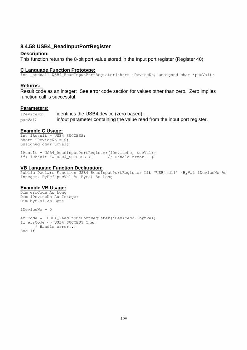
109
8.4.58 USB4_ReadInputPortRegister Description: This function returns the 8-bit port value stored in the Input port register (Register 40) C Language Function Prototype: int _stdcall USB4_ReadInputPortRegister(short iDevi ceNo, unsigned char *pucVal);
Returns: Result code as an integer: See error code section for values other than zero. Zero implies function call is successful. Parameters: iDeviceNo : identifies the USB4 device (zero based). pucVal : in/out parameter containing the value read from the input port register. Example C Usage: int iResult = USB4_SUCCESS; short iDeviceNo = 0; unsigned char ucVal; iResult = USB4_ReadInputPortRegister(iDeviceNo, &uc Val); if( iResult != USB4_SUCCESS ) // Handle error...
VB Language Function Declaration: Public Declare Function USB4_ReadInputPortRegister Lib "USB4.dll" (ByVal iDeviceNo As Integer, ByRef pucVal As Byte) As Long
Example VB Usage: Dim errCode As Long Dim iDeviceNo As Integer Dim bytVal As Byte iDeviceNo = 0 errCode = USB4_ReadInputPortRegister(iDeviceNo, by tVal) If errCode <> USB4_SUCCESS Then ‘ Handle error... End If
110
8.4.59 USB4_ReadOutputLatch Description: This function returns the contents of the specified counter’s Output Latch Register.
C Language Function Prototype: int _stdcall USB4_ReadOutputLatch(short iDeviceNo, short iEncoder, unsigned long *pulVal);
Returns: Result code as an integer: See error code section for values other than zero. Zero implies function call is successful. Parameters: iDeviceNo : identifies the USB4 device (zero based). iEncoder: identifies the encoder channel (zero based, 0-3). pulVal : in/out parameter that contains the Output Latch Register value. Example C Usage: int iResult = USB4_SUCCESS; short iDeviceNo = 0; short iEncoder = 0; unsigned long ulVal = 0; iResult = USB4_ReadOutputLatch(iDeviceNo, iEncoder, &ulVal); if ( iResult != USB4_SUCCESS ) // Handle error...
VB Language Function Declaration: Public Declare Function USB4_ReadOutputLatch Lib "U SB4.dll" (ByVal iDeviceNo As Integer, ByVal iEncoder As Integer, ByRef pulVal As Long) As Long
Example VB Usage: Dim errCode As Long Dim iDeviceNo As Integer Dim iEncoder As Integer Dim ulVal As Long iDeviceNo = 0 iEncoder = 0 errCode = USB4_ReadOutputLatch(iDeviceNo, iEncoder, lVal) If errCode <> USB4_SUCCESS then ‘ Handle error... End If
111
8.4.60 USB4_ReadOutputPortRegister Description: This function returns the contents of the Output port register (Register 46) C Language Function Prototype: int _stdcall USB4_ReadOutputPortRegister(short iDev iceNo, unsigned char *pucVal);
Returns: Result code as an integer: See error code section for values other than zero. Zero implies function call is successful. Parameters: iDeviceNo : identifies the USB4 device (zero based). pucVal : in/out parameter containing value read from the output port register. Bits 7-0: output port bits 7 to 0. Example C Usage: int iResult = USB4_SUCCESS; short iDeviceNo = 0; unsigned char ucVal; iResult = USB4_ReadOutputPortRegister(iDeviceNo, &u cVal); if( iResult != USB4_SUCCESS ) // Handle error...
VB Language Function Declaration: Public Declare Function USB4_ReadOutputPortRegister Lib "USB4.dll" (ByVal iDeviceNo As Integer, ByRef pucVal As Byte) As Long
Example VB Usage: Dim errCode As Long Dim iDeviceNo As Integer Dim bytVal As Byte iDeviceNo = 0 errCode = USB4_ReadOutputPortRegister(iDeviceNo, b ytVal) If errCode <> USB4_SUCCESS Then ‘ Handle error... End If
112
8.4.61 USB4_ReadRegister Description: This function returns the contents of a specified USB4 register. C Language Function Prototype: int _stdcall USB4_ReadRegister(short iDeviceNo, sho rt iRegister, unsigned long *pulVal);
Returns: Result code as an integer: See error code section for values other than zero. Zero implies function call is successful. Parameters: iDeviceNo : identifies the USB4 device (zero based). iRegister : identifies the specific register to read. Valid registers are 0 – 67. pulVal : in/out parameter containing value read from the specified register. Example C Usage: int iResult = USB4_SUCCESS; short iDeviceNo = 0; short iRegister = 0; unsigned long ulVal = 0; iResult = USB4_ReadRegister(iDeviceNo, iRegister, & ulVal); if( iResult != USB4_SUCCESS ) // Handle error...
VB Language Function Declaration: Public Declare Function USB4_ReadRegister Lib "USB4 .dll" (ByVal iDeviceNo As Integer, ByVal iRegister As Integer, ByRef pulVal As Long) A s Long
Example VB Usage: Dim errCode As Long Dim iDeviceNo As Integer Dim iRegister As Integer Dim lVal As Long iDeviceNo = 0 iRegister = 0 errCode = USB4_ReadRegister(iDeviceNo, iRegister, lVal) If errCode <> USB4_SUCCESS Then ‘ Handle error... End If

113
8.4.62 USB4_ReadTimeAndCounts Description: This function reads the Timestamp Latch and each encoder’s Output Latch. C Language Function Prototype: int _stdcall USB4_ReadTimeAndCounts(short iDeviceNo , unsigned long *pulCounts, unsigned long *pulTimeStamp);
Returns: Result code as an integer: See error code section for values other than zero. Zero implies function call is successful. Parameters: iDeviceNo : identifies the USB4 device (zero based). pulCounts : array of 4 longs containing the Output Latch value (unsigned 24-bit integer) for
each encoder channel. pulTimeStamp : contains Timestamp Latch value (unsigned 32-bit integer) Example C Usage: int iResult = USB4_SUCCESS; short iDeviceNo = 0; unsigned long ulCounts [4] = 0, 0, 0, 0; unsigned long ulTimeStamp = 0; iResult = USB4_ReadTimeAndCounts(iDeviceNo, ulCount s, &ulTimeStamp); if ( iResult != USB4_SUCCESS ) // Handle error...
VB Language Function Declaration: Public Declare Function USB4_ReadTimeAndCounts Lib "USB4.dll" (ByVal iDeviceNo As Integer, ByRef pulCounts As Long, ByRef pulTimeStam p As Long) As Long
Example VB Usage: Dim errCode As Long Dim iDeviceNo As Integer Dim lCounts(3) As Long Dim lTimeStamp As Long iDeviceNo = 0 errCode = USB4_ReadTimeAndCounts(iDeviceNo, lCounts (0), lTimeStamp) If errCode <> USB4_SUCCESS then ‘ Handle error… End If
114
8.4.63 USB4_ReadTimeStamp Description: This function reads the Timestamp Latch register. C Language Function Prototype: int _stdcall USB4_ReadTimeStamp(short iDeviceNo, un signed long *pulVal);
Returns: Result code as an integer: See error code section for values other than zero. Zero implies function call is successful. Parameters: iDeviceNo : identifies the USB4 device (zero based). pulVal : contains the Timestamp Latch value. Example C Usage: int iResult = USB4_SUCCESS; short iDeviceNo = 0; unsigned long ulVal = 0; iResult = USB4_ReadTimeStamp(iDeviceNo, &ulVal); if ( iResult != USB4_SUCCESS ) // Handle error...
VB Language Function Declaration: Public Declare Function USB4_ReadTimeStamp Lib "USB 4.dll" (ByVal iDeviceNo As Integer, ByRef pulVal As Long) As Long
Example VB Usage: Dim errCode As Long Dim iDeviceNo As Integer Dim lVal As Long iDeviceNo = 0 errCode = USB4_ReadTimeStamp(iDeviceNo, lVal) If errCode <> USB4_SUCCESS then ‘ Handle error… End If
115
8.4.64 USB4_ReadUnlatchedTimeAndCounts Description: This function reads the Timestamp register and each encoder’s count register. C Language Function Prototype: int _stdcall USB4_ReadUnlatchedTimeAndCounts(short iDeviceNo, unsigned long *pulCounts, unsigned long *pulTimeStamp);
Returns: Result code as an integer: See error code section for values other than zero. Zero implies function call is successful. Parameters: iDeviceNo : identifies the USB4 device (zero based). pulCounts : array of 4 longs containing the counter value (unsigned 24-bit integer) for each
channel. pulTimeStamp : contains the Timestamp register value. Example C Usage: int iResult = USB4_SUCCESS; short iDeviceNo = 0; unsigned long ulCounts [4] = 0, 0, 0, 0; unsigned long ulTimeStamp = 0; iResult = USB4_ReadUnlatchedTimeAndCounts(iDeviceNo , ulCounts, &ulTimeStamp); if ( iResult != USB4_SUCCESS ) // Handle error...
VB Language Function Declaration: Public Declare Function USB4_ReadUnlatchedTimeAndCo unts Lib "USB4.dll" (ByVal iDeviceNo As Integer, ByRef pulCounts As Long, ByRe f pulTimeStamp As Long) As Long
Example VB Usage: Dim errCode As Long Dim iDeviceNo As Integer Dim lCounts(3) As Long Dim lTimeStamp As Long iDeviceNo = 0 errCode = USB4_ReadUnlatchedTimeAndCounts(iDeviceNo , lCounts(0), lTimeStamp) If errCode <> USB4_SUCCESS then ‘ Handle error… End If

116
8.4.65 USB4_ReadUserEEPROM Description: This function reads up to 64 bytes of data from the USB4’s user EEPROM. C Language Function Prototype: int _stdcall USB4_ReadUserEEPROM(short iDeviceNo, u nsigned char startAddress, unsigned char bytesToRead, unsigned char * pucDataA rray);
Returns: Result code as an integer: See error code section for values other than zero. Zero implies function call is successful. Parameters: iDeviceNo: identifies the USB4 device (zero based). startAddress: identifies the user EEPROM starting address from 0 to 63. bytesToRead: identifies the number of user EEPROM bytes to read. pucDataArray: array of bytes that will contain the data read from EEPROM. Example C Usage: int iResult = USB4_SUCCESS; unsigned char ucStartAddress = 0; unsigned char ucBytesToRead = 64; unsigned char ucDataArray[64] = “\0“; iResult = USB4_ReadUserEEPROM(iDeviceNo, ucStartAdd ress, ucBytesToRead, ucDataArray); if ( iResult != USB4_SUCCESS ) // Handle error...
VB Language Function Declaration: Public Declare Function USB4_ReadUserEEPROM Lib "US B4.dll" (ByVal iDeviceNo As Integer, ByVal bytStartAddress As Byte, ByVal bytBy tesToRead As Byte, ByRef bytDataArrary) As Long
Example VB Usage: Dim errCode As Long Dim bytStartAddress As Byte Dim bytBytesToRead As Byte Dim bytDataArray(63) As Byte iDeviceNo = 0 bytStartAddress = 0 bytBytesToRead = 64 errCode = USB4_ReadUserEEPROM(iDeviceNo, bytStartAd dress, bytBytesToRead, bytDataArray(0)) If errCode <> USB4_SUCCESS then ‘ Handle error… End If

117
8.4.66 USB4_ResetCount Description: This function sets the specified encoder channel’s counter value to zero. C Language Function Prototype: int _stdcall USB4_ResetCount(short iDeviceNo, short iEncoder);
Returns: Result code as an integer: See error code section for values other than zero. Zero implies function call is successful. Parameters: iDeviceNo : identifies the USB4 device (zero based). iEncoder: identifies the encoder channel (zero based, 0-3). Example C Usage: int iResult = USB4_SUCCESS; short iDeviceNo = 0; short iEncoder = 0; iResult = USB4_ResetCount(iDeviceNo, iEncoder); if ( iResult != USB4_SUCCESS ) // Handle error...
VB Language Function Declaration: Public Declare Function USB4_ResetCount Lib "USB4.d ll" (ByVal iDeviceNo As Integer, ByVal iEncoder As Integer) As Long
Example VB Usage: Dim errCode As Long Dim iDeviceNo As Integer Dim iEncoder As Integer iDeviceNo = 0 iEncoder = 0 errCode = USB4_ResetCount(iDeviceNo, iEncoder) If errCode <> USB4_SUCCESS then ‘ Handle error… End If
118
8.4.67 USB4_ResetTimeStamp Description: This function sets the Timestamp counter value to zero. C Language Function Prototype: int _stdcall USB4_ResetTimeStamp(short iDeviceNo);
Returns: Result code as an integer: See error code section for values other than zero. Zero implies function call is successful. Parameters: iDeviceNo : identifies the USB4 device (zero based). Example C Usage: int iResult = USB4_SUCCESS; short iDeviceNo = 0; iResult = USB4_ResetTimeStamp(iDeviceNo); if ( iResult != USB4_SUCCESS ) // Handle error...
VB Language Function Declaration: Public Declare Function USB4_ResetTimeStamp Lib "US B4.dll" (ByVal iDeviceNo As Integer) As Long
Example VB Usage: Dim errCode As Long Dim iDeviceNo As Integer iDeviceNo = 0 errCode = USB4_ResetTimeStamp(iDeviceNo) If errCode <> USB4_SUCCESS then ‘ Handle error End If
119
8.4.68 USB4_ReadSavedParameters Description: This function loads each encoder’s control register and preset register from the value saved in EEPROM. Each encoder’s control and preset setting are written to the EEPROM using USB4_SaveParameters(…). C Language Function Prototype: int _stdcall USB4_ReadSavedParameters(short iDevice No);
Returns: Result code as an integer: See error code section for values other than zero. Zero implies function call is successful. Parameters: iDeviceNo : identifies the USB4 device (zero based). Example C Usage: int iResult = USB4_SUCCESS; short iDeviceNo = 0; iResult = USB4_ReadSavedParameters(iDeviceNo); if ( iResult != USB4_SUCCESS ) // Handle error...
VB Language Function Declaration: Public Declare Function USB4_ReadSavedParameters Li b "USB4.dll" (ByVal iDeviceNo As Integer) As Long
Example VB Usage: Dim errCode As Long Dim iDeviceNo As Integer iDeviceNo = 0 errCode = USB4_ReadSavedParameters(iDeviceNo) If errCode <> USB4_SUCCESS then ‘ Handle error End If

120
8.4.69 USB4_RestoreFactoryParameters Description: This function loads each encoder counter’s control register with 0x00874000 and each encoder counter’s preset register with 0x000001F3. A call to USB4_SaveParameters(…) is then made to save the settings to EEPROM. C Language Function Prototype: int _stdcall USB4_RestoreFactoryParameters(short iD eviceNo);
Returns: Result code as an integer: See error code section for values other than zero. Zero implies function call is successful. Parameters: iDeviceNo : identifies the USB4 device (zero based). Example C Usage: int iResult = USB4_SUCCESS; short iDeviceNo = 0; iResult = USB4_RestoreFactoryParameters(iDeviceNo); if ( iResult != USB4_SUCCESS ) // Handle error...
VB Language Function Declaration: Public Declare Function USB4_RestoreFactoryParamete rs Lib "USB4.dll" (ByVal iDeviceNo As Integer) As Long
Example VB Usage: Dim errCode As Long Dim iDeviceNo As Integer iDeviceNo = 0 errCode = USB4_RestoreFactoryParameters(iDeviceNo) If errCode <> USB4_SUCCESS then ‘ Handle error End If
121
8.4.70
8.4.71 USB4_SetA2DSamplingFrequency Description: This function sets the Current A/D Sampling Frequency flag which is contained in bit 7 of the Command register. If this bit is clear (0), the A/D sampling frequency is 11.111 kHz. If this bit is set (1), the A/D sampling frequency is 44.444 kHz. Note: After setting the new A2D Sampling Frequency, a 15 millisecond delay is needed for the
A/D to settle. C Language Function Prototype: int _stdcall USB4_SetA2DSamplingFrequency(short iDe viceNo, unsigned short uiVal);
Returns: Result code as an integer: See error code section for values other than zero. Zero implies function call is successful. Parameters: iDeviceNo : identifies the USB4 device (zero based). uiVal : contains new the A/D Sampling Frequency flag 0 = 11.111 kHz
1 = 44.444 kHz Example C Usage: int iResult = USB4_SUCCESS; short iDeviceNo = 0; unsigned short uiA2DSamplingFrequencyFlag = 1; // Sample at 44.444 kHz iResult = USB4_SetA2DSamplingFrequency(iDeviceNo, u iA2DSamplingFrequencyFlag); if ( iResult != USB4_SUCCESS ) // Handle error...
VB Language Function Declaration: Public Declare Function USB4_SetA2DSamplingFrequenc y Lib "USB4.dll" (ByVal iDeviceNo As Integer, ByVal uiVal As Integer) As Long
Example VB Usage: Dim errCode As Long Dim iDeviceNo As Integer Dim uiA2DSamplingFrequencyFlag As Integer iDeviceNo = 0 uiA2DSamplingFrequencyFlag = 0 ‘ Sample at 11.111 k Hz errCode = USB4_GetA2DSamplingFrequency(iDeviceNo, u iA2DSamplingFrequencyFlag) If errCode <> USB4_SUCCESS then ‘ Handle error... End If
122
8.4.72 USB4_SaveParameters Description: This function saves each encoder’s control register and preset register to EEPROM. C Language Function Prototype: int _stdcall USB4_SaveParameters(short iDeviceNo);
Returns: Result code as an integer: See error code section for values other than zero. Zero implies function call is successful. Parameters: iDeviceNo : identifies the USB4 device (zero based). Example C Usage: int iResult = USB4_SUCCESS; short iDeviceNo = 0; iResult = USB4_SaveParameters(iDeviceNo); if ( iResult != USB4_SUCCESS ) // Handle error...
VB Language Function Declaration: Public Declare Function USB4_SaveParameters Lib "US B4.dll" (ByVal iDeviceNo As Integer) As Long
Example VB Usage: Dim errCode As Long Dim iDeviceNo As Integer iDeviceNo = 0 errCode = USB4_SaveParameters(iDeviceNo) If errCode <> USB4_SUCCESS then ‘ Handle error End If
123
8.4.73
8.4.74 USB4_SetCaptureEnabled Description: This function sets a boolean value that determines whether any trigger will cause a transfer from the specified encoder counter to encoder output latch. C Language Function Prototype: int _stdcall USB4_SetCaptureEnabled(short iDeviceNo , short iEncoder, BOOL bVal); Returns: Result code as an integer: See error code section for values other than zero. Zero implies function call is successful. Parameters: iDeviceNo : identifies the USB4 device (zero based). iEncoder: identifies the encoder channel (zero based, 0-3). bVal : TRUE: any trigger will cause a transfer from counter to output latch. FALSE: triggers will not cause a transfer from counter to output latch. Example C Usage: int iResult = USB4_SUCCESS; short iDeviceNo = 0; short iEncoder = 0; BOOL bVal = TRUE; iResult = USB4_SetCaptureEnabled(iDeviceNo, iEncode r, bVal); if ( iResult != USB4_SUCCESS ) // Handle error...
VB Language Function Declaration: Public Declare Function USB4_SetCaptureEnabled Lib "USB4.dll" (ByVal iDeviceNo As Integer, ByVal iEncoder As Integer, ByVal bVal As L ong) As Long
Example VB Usage: Dim errCode As Long Dim iDeviceNo As Integer Dim iEncoder As Integer Dim bVal as Long iDeviceNo = 0 iEncoder = 0 bVal = True errCode = USB4_SetCaptureEnabled(iDeviceNo, iEncode r, bVal) if errCode <> USB4_SUCCESS then ‘ Handle error… End If
124
8.4.75 USB4_SetControlMode Description: This function sets the Control Register for the specified encoder channel. C Language Function Prototype: int _stdcall USB4_SetControlMode(short iDeviceNo, s hort iEncoder, unsigned long ulVal); Returns: Result code as an integer: See error code section for values other than zero. Zero implies function call is successful. Parameters: iDeviceNo : identifies the USB4 device (zero based). iEncoder: identifies the encoder channel (zero based, 0-3). ulVal: value to be written to the encoder Control register Example C Usage: int iResult = USB4_SUCCESS; short iDeviceNo = 0; short iEncoder = 0; unsigned long ulVal = 0xF4000; iResult = USB4_SetControlMode(iDeviceNo, iEncoder, ulVal); if ( iResult != USB4_SUCCESS ) // Handle error...
VB Language Function Declaration: Public Declare Function USB4_SetControlMode Lib "US B4.dll" (ByVal iDeviceNo As Integer, ByVal iEncoder As Integer, ByVal ulVal As Long) As Long
Example VB Usage: Dim errCode As Long Dim iDeviceNo As Integer Dim iEncoder As Integer Dim lVal As Long iDeviceNo = 0 iEncoder = 0 lVal = &hF4000 errCode = USB4_SetControlMode(iDeviceNo, iEncoder, lVal) if errCode <> USB4_SUCCESS then ‘ Handle error… End If
125
8.4.76 USB4_SetCount Description: This function writes a value to the counter for the specified encoder channel. Note: USB4_SetCount forces the internal counter’s value to a specified value without permanently changing the Preset register. In fact, USB4_SetCount(…) utilizes the Preset Register for transferring data to the internal counter, but the original value of Preset Register is restored at the end of function call. When writing an application that looks for changes in Preset Register, the programmer must be aware of this temporary change of value. C Language Function Prototype: int _stdcall USB4_SetCount(short iDeviceNo, short i Encoder, unsigned long ulVal);
Returns: Result code as an integer: See error code section for values other than zero. Zero implies function call is successful. Parameters: iDeviceNo : identifies the USB4 device (zero based). iEncoder: identifies the encoder channel (zero based, 0-3). ulVal : value to be written to the counter register (unsigned 24-bit integer). Example C Usage: int iResult = USB4_SUCCESS; short iDeviceNo = 0; short iEncoder = 0; unsigned long ulVal= 200; iResult = USB4_SetCount(iDeviceNo, iEncoder, ulVal) ; if ( iResult != USB4_SUCCESS ) // Handle error...
VB Language Function Declaration: Public Declare Function USB4_SetCount Lib "USB4.dll " (ByVal iDeviceNo As Integer, ByVal iEncoder As Integer, ByVal ulVal As Long) As Long
Example VB Usage: Dim errCode As Long Dim iDeviceNo As Integer Dim iEncoder As Integer Dim lVal As Long iDeviceNo = 0 iEncoder = 0 lVal = 200 errCode = USB4_SetCount(iDeviceNo, iEncoder, lVal) If errCode <> USB4_SUCCESS then ‘ Handle error... End If
126
8.4.77 USB4_SetCounterEnabled Description: This function enables or disables the specified encoder channel. C Language Function Prototype: int _stdcall USB4_SetCounterEnabled(short iDeviceNo , short iEncoder, BOOL bVal); Returns: Result code as an integer: See error code section for values other than zero. Zero implies function call is successful. Parameters: iDeviceNo : identifies the USB4 device (zero based). iEncoder: identifies the encoder channel (zero based, 0-3). bVal : TRUE: enable the encoder channel FALSE: disable the encoder channel Example C Usage: int iResult = USB4_SUCCESS; short iDeviceNo = 0; short iEncoder = 0; BOOL bVal = TRUE; iResult = USB4_SetCounterEnabled(iDeviceNo, iEncode r, bVal); if ( iResult != USB4_SUCCESS ) // Handle error...
VB Language Function Declaration: Public Declare Function USB4_SetCounterEnabled Lib "USB4.dll" (ByVal iDeviceNo As Integer, ByVal iEncoder As Integer, ByVal bVal As L ong) As Long
Example VB Usage: Dim errCode As Long Dim iDeviceNo As Integer Dim iEncoder As Integer Dim bVal as Long iDeviceNo = 0 iEncoder = 0 bVal = True errCode = USB4_SetCounterEnabled(iDeviceNo, iEncode r, bVal) if errCode <> USB4_SUCCESS then ‘ Handle error… End If
127
8.4.78 USB4_SetCounterMode Description: This function sets the 2 counter mode bits in the Control register for the specified encoder channel. The remaining bits of the Control register are not changed. C Language Function Prototype: int _stdcall USB4_SetCounterMode(short iDeviceNo, s hort iEncoder, short iVal);
Returns: Result code as an integer: See error code section for values other than zero. Zero implies function call is successful. Parameters: iDeviceNo : identifies the USB4 device (zero based). iEncoder: identifies the encoder channel (zero based, 0-3). iVal : parameter containing the counter mode. 0 = 24-bit counter. 1 = 24-bit counter with preset register in range-limit mode . 2 = 24-bit counter with preset register in non-recycle mode. 3 = 24-bit counter with preset register in modulo-N mode. Example C Usage: int iResult = USB4_SUCCESS; short iDeviceNo = 0; short iEncoder = 0; short iVal = 0; iResult = USB4_SetCounterMode(iDeviceNo, iEncoder, iVal); if ( iResult != USB4_SUCCESS ) // Handle error...
VB Language Function Declaration: Public Declare Function USB4_SetCounterMode Lib "US B4.dll" (ByVal iDeviceNo As Integer, ByVal iEncoder As Integer, ByVal iVal As I nteger) As Long
Example VB Usage: Dim errCode As Long Dim iDeviceNo As Integer Dim iEncoder As Integer Dim iVal As Integer iDeviceNo = 0 iEncoder = 0 iVal = 0 errCode = USB4_SetCounterMode(iDeviceNo, iEncoder, iVal) If errCode <> USB4_SUCCESS then ‘ Handle error... End If
128
8.4.79 USB4_SetD2A Description: This function writes a 12 bit value to a specified digital to analog (D2A) converter channel. The analog voltage outputs are on connector J10. C Language Function Prototype: int _stdcall USB4_SetD2A (short iDeviceNo, short iD 2AChannel, usigned short uiD2Avalue, BOOL bUpdateD2AChannelsNow);
Returns: Result code as an integer: See error code section for values other than zero. Zero implies function call is successful. Parameters: iDeviceNo : identifies the USB4 device (zero based). iD2AChannel : identifies a specified D2A channel (0-3). uiD2AValue : value written to D2A converter from 0 (0V output) to 4095 (5V output) bUpdateD2AChannelsNow : TRUE: update all 4 analog output voltages immediately FALSE: latch the D2A value but do not update output analog voltage. This parameter is used in cases where all 4 analog output voltages
need to change simultaneously. In this case, call USB4_SetD2A(…) with this parameter set to FALSE for the first 3 channels, then call USB4_SetD2A(…) for the 4th channel with the parameter set to TRUE.
Example C Usage: int iResult = USB4_SUCCESS; short iDeviceNo = 0; short iD2AChannel = 1; unsigned short uiD2AValue = 1023; BOOL bUpdateD2AchannelsNow = TRUE; iResult = USB4_SetD2A(iDeviceNo, iD2AChannel, uiD2A value, bUpdateD2AchannelsNow); if ( iResult != USB4_SUCCESS ) // Handle error...
VB Language Function Declaration: Public Declare Function USB4_SetD2A Lib "USB4.dll" (ByVal iDeviceNo As Integer, ByVal iD2AChannel As Integer, ByVal uiD2AValue As Integer , ByVal bUpdateD2AChannelsNow As Integer) As Long
129
Example VB Usage: Dim errCode As Long Dim iDeviceNo As Integer Dim iD2AChannel As Integer Dim uiD2AValue As Integer Dim bUpdateD2AChannelsNow As Integer iDeviceNo = 0 iD2AChannel = 1 uiD2AValue = 1023 bUpdateD2AchannelsNow = True errCode = USB4_SetD2A(iDeviceNo, iD2AChannel, uiD2A DValue) If errCode <> USB4_SUCCESS then ‘ Handle error... End If
130
8.4.80 USB4_SetD2AControlMode Description: This function puts all 4 D2A outputs in a high impedance state or pulled to GND. USB4_SetD2A(…) will work normally to restore the output voltage for a channel. C Language Function Prototype: int _stdcall USB4_SetD2AControlMode (short iDeviceN o, usigned char ucMode);
Returns: Result code as an integer: See error code section for values other than zero. Zero implies function call is successful. Parameters: iDeviceNo : identifies the USB4 device (zero based). ucMode: output setting 0 = reserved.
1 = output voltage on all channels are set to high impedance. 2 = output voltage on all channels pulled to GND by 2.5k resistor. 3 = output voltage on all channels pulled to GND by 100k resistor.
Example C Usage: int iResult = USB4_SUCCESS; short iDeviceNo = 0; unsigned char ucMode = 1; iResult = USB4_SetD2AControlMode(iDeviceNo, ucMode) ; if ( iResult != USB4_SUCCESS ) // Handle error...
VB Language Function Declaration: Public Declare Function USB4_SetD2AControlMode Lib "USB4.dll" (ByVal iDeviceNo As Integer, ByVal bytMode As Byte) As Long
Example VB Usage: Dim errCode As Long Dim iDeviceNo As Integer Dim bytMode As Byte iDeviceNo = 0 bytMode = 1 errCode = USB4_SetD2AControlMode(iDeviceNo, bytMode ) If errCode <> USB4_SUCCESS then ‘ Handle error... End If
131
8.4.81 USB4_SetDigitalInputTriggerConfig Description: This function is used to configure the digital input trigger settings for event based triggering. See Section 6.1.4 Event Based Trigger - Input Port Simple External Trigger Registers C Language Function Prototype: int _stdcall USB4_SetDigitalInputTriggerConfig(shor t iDeviceNo, BOOL *pbEnableTrigger, BOOL *pbTriggerOnRisingEdge);
Returns: Result code as an integer: See error code section for values other than zero. Zero implies function call is successful. Parameters: iDeviceNo : identifies the USB4 device (zero based). pbEnableTrigger : array of eight booleans which enable/disable trigger generation for each
digital input pin. TRUE = trigger enabled. FALSE = trigger disabled. pbTriggerOnRisingEdge : array of eight booleans which determine the trigger’s active edge for
each digital input pin. TRUE = rising edge. FALSE = falling edge. Example C Usage: int iResult = USB4_SUCCESS; int iDeviceNo = 0; // enable trigger on input 3 BOOL bEnableTrigger[8] = FALSE, FALSE, FALSE, FALS E, TRUE, FALSE, FALSE, FALSE; // trigger on rising edge of input 3 BOOL bTriggerOnRisingEdge[8] = FALSE, FALSE, FALSE , FALSE, TRUE, FALSE, FALSE, FALSE; iResult = USB4_SetDigitalInputTriggerConfig(iDevice No, bEnableTrigger, bTriggerOnRisingEdge); if ( iResult != USB4_SUCCESS ) // Handle error...
132
VB Language Function Declaration: Public Declare Function USB4_SetDigitalInputTrigger Config Lib "USB4.dll" (ByVal iDeviceNo As Integer, ByRef bEnableTrigger As Long, ByRef bTriggerOnRisingEdge As Long) As Long
Example VB Usage: Dim errCode As Long Dim iDeviceNo As Integer Dim bEnableTrigger(0 To 7) As Long Dim bTriggerOnRisingEdge (0 To 7) As Long iDeviceNo = 0 bEnableTrigger(0) = True ‘ enable trigger on input 0 bTriggerOnRisingEdge(0) = True ‘ trigger on rising edge of input 0 errCode = USB4_GetDigitalInputTriggerConfig (iDevic eNo, bEnableTrigger(0), bTriggerOnRisingEdge(0)) If errCode <> USB4_SUCCESS then ‘ Handle error... End If
133
8.4.82 USB4_SetEnableEncoder Description: This function sets a boolean value that determines whether the master enable for an encoder channel is set, (must be set to true to count). C Language Function Prototype: int _stdcall USB4_SetEnableEncoder(short iDeviceNo, short iEncoder, BOOL bVal); Returns: Result code as an integer: See error code section for values other than zero. Zero implies function call is successful. Parameters: iDeviceNo : identifies the USB4 device (zero based). iEncoder: identifies the encoder channel (zero base d, 0-3).
bVal : in/out boolean parameter identifying whether the counter is enabled. Example C Usage: int iResult = USB4_SUCCESS; short iDeviceNo = 0; short iEncoder = 0; BOOL bVal = FALSE; iResult = USB4_SetEnableEncoder(iDeviceNo, iEncoder , bVal); if ( iResult != USB4_SUCCESS ) // Handle error...
VB Language Function Declaration: Public Declare Function USB4_SetEnableEncoder Lib " USB4.dll" (ByVal iDeviceNo As Integer, ByVal iEncoder As Integer, ByVal bVal As L ong) As Long
Example VB Usage: Dim errCode As Long Dim iDeviceNo As Integer Dim iEncoder As Integer Dim bVal as Long iDeviceNo = 0 iEncoder = 0 bVal = True errCode = USB4_SetEnableEncoder(iDeviceNo, iEncoder , bVal) If errCode <> USB4_SUCCESS then ‘ Handle error... End If
134
8.4.83 USB4_SetEnableIndex Description: This enables or disables index detection for the specified encoder counter. When enabled, USB4_SetPresetOnIndex(…) can be used to determine how the counter responds to an index signal. C Language Function Prototype: int _stdcall USB4_SetEnableIndex(short iDeviceNo, s hort iEncoder, BOOL bVal);
Returns: Result code as an integer: See error code section for values other than zero. Zero implies function call is successful. Parameters: iDeviceNo : identifies the USB4 device (zero based). iEncoder: identifies the encoder channel (zero based, 0-3). bVal : TRUE = enable index detection. FALSE = disable index detection. Example C Usage: int iResult = USB4_SUCCESS; short iDeviceNo = 0; short iEncoder = 0; BOOL bVal = FALSE; iResult = USB4_SetEnableIndex(iDeviceNo, iEncoder, bVal); if ( iResult != USB4_SUCCESS ) // Handle error...
VB Language Function Declaration: Public Declare Function USB4_SetEnableIndex Lib "US B4.dll" (ByVal iDeviceNo As Integer, ByVal iEncoder As Integer, ByVal bVal As L ong) As Long
Example VB Usage: Dim errCode As Long Dim iDeviceNo As Integer Dim iEncoder As Integer Dim bVal as Long iDeviceNo = 0 iEncoder = 0 bVal = True errCode = USB4_SetEnableIndex(iDeviceNo, iEncoder, bVal) If errCode <> USB4_SUCCESS then ‘ Handle error... End If
135
8.4.84 USB4_SetEnableIndexOnMatch Description: This enables or disables index detection for a specified encoder counter when a match event occurs. When enabled and the encoder’s counter is equal to the match register value, then the index detection features are enabled. A subsequent index signal will either reset or preset the counter value and the index detection will be disabled until the next match event occurs. C Language Function Prototype: int _stdcall USB4_SetEnableIndexOnMatch(short iDevi ceNo, short iEncoder, BOOL bVal);
Returns: Result code as an integer: See error code section for values other than zero. Zero implies function call is successful. Parameters: iDeviceNo : identifies the USB4 device (zero based). iEncoder: identifies the encoder channel (zero based, 0-3). bVal : TRUE = enable index detection on match. FALSE = index detection is based on the current state of the enable index flag in the control register. Refer to USB4_SetEnableIndex or USB4_GetEnableIndex. Example C Usage: int iResult = USB4_SUCCESS; short iDeviceNo = 0; short iEncoder = 0; BOOL bVal = FALSE; iResult = USB4_SetEnableIndexOnMatch(iDeviceNo, iEn coder, bVal); if ( iResult != USB4_SUCCESS ) // Handle error...
VB Language Function Declaration: Public Declare Function USB4_SetEnableIndexOnMatch Lib "USB4.dll" (ByVal iDeviceNo As Integer, ByVal iEncoder As Integer, ByVal bVal As L ong) As Long
Example VB Usage: Dim errCode As Long Dim iDeviceNo As Integer Dim iEncoder As Integer Dim bVal as Long iDeviceNo = 0 iEncoder = 0 bVal = True errCode = USB4_SetEnableIndexOnMatch(iDeviceNo, iEn coder, bVal) If errCode <> USB4_SUCCESS then ‘ Handle error... End If
136
8.4.85 USB4_SetEStopBit Description: This function sets or clears the Emergency Stop (E-Stop) state. C Language Function Prototype: int _stdcall USB4_SetEStopBit(short iDeviceNo, unsi gned char ucVal);
Returns: Result code as an integer: See error code section for values other than zero. Zero implies function call is successful. Parameters: iDeviceNo : identifies the USB4 device (zero based). ucVal : 0x00 = clear E-Stop state 0x01 = set E-Stop state Example C Usage: int iResult = USB4_SUCCESS; unsigned char ucVal = 0x00; iResult = USB4_SetEStopBit(iDeviceNo, ucVal); if ( iResult != USB4_SUCCESS ) // Handle error...
VB Language Function Declaration: Public Declare Function USB4_SetEStopBit Lib "USB4. dll" (ByVal iDeviceNo As Integer, ByVal bytVal As Byte) As Long
Example VB Usage: Dim errCode As Long Dim iDeviceNo As Integer Dim bytVal as Byte iDeviceNo = 0 bytVal = 0 errCode = USB4_SetEStopBit(iDeviceNo, bytVal) If errCode <> USB4_SUCCESS then ‘ Handle error... End If
137
8.4.86 USB4_SetForward Description: This function sets a boolean value that indicates whether the”B” quadrature signal is inverted for the specified encoder channel. This will affect the count direction. C Language Function Prototype: int _stdcall USB4_SetForward(short iDeviceNo, short iEncoder, BOOL bVal);
Returns: Result code as an integer: See error code section for values other than zero. Zero implies function call is successful. Parameters: iDeviceNo : identifies the USB4 device (zero based). iEncoder: identifies the encoder channel (zero based, 0-3). bVal : TRUE: invert “B” quadrature input FALSE: do not invert “B” quadrature input Example C Usage: int iResult = USB4_SUCCESS; short iDeviceNo = 0; short iEncoder = 0; BOOL bVal = TRUE; iResult = USB4_SetForward(iDeviceNo, iEncoder, bVal ); if ( iResult != USB4_SUCCESS ) // Handle error...
VB Language Function Declaration: Public Declare Function USB4_SetForward Lib "USB4.d ll" (ByVal iDeviceNo As Integer, ByVal iEncoder As Integer, ByVal bVal As Long) As L ong
Example VB Usage: Dim errCode As Long Dim iDeviceNo As Integer Dim iEncoder As Integer Dim bVal As Long iDeviceNo = 0 iEncoder = 0 bVal = True errCode = USB4_SetForward(iDeviceNo, iEncoder, bVal ) If errCode <> USB4_SUCCESS then ‘ Handle error... End If
138
8.4.87 USB4_SetInvertIndex Description: This function takes a boolean value that determines if the index pulse for the specified encoder channel is active high or active low. C Language Function Prototype: int _stdcall USB4_SetInvertIndex(short iDeviceNo, s hort iEncoder, BOOL bVal);
Returns: Result code as an integer: See error code section for values other than zero. Zero implies function call is successful. Parameters: iDeviceNo : identifies the USB4 device (zero based). iEncoder: identifies the encoder channel (zero based, 0-3). bVal : TRUE: active low index pulse FALSE: active high index pulse Example C Usage: int iResult = USB4_SUCCESS; short iDeviceNo = 0; short iEncoder = 0; BOOL bVal = FALSE; iResult = USB4_SetInvertIndex(iDeviceNo, iEncoder, bVal); if ( iResult != USB4_SUCCESS ) // Handle error...
VB Language Function Declaration: Public Declare Function USB4_SetInvertIndex Lib "US B4.dll" (ByVal iDeviceNo As Integer, ByVal iEncoder As Integer, ByVal bVal As L ong) As Long
Example VB Usage: Dim errCode As Long Dim iDeviceNo As Integer Dim iEncoder As Integer Dim bVal as Long iDeviceNo = 0 iEncoder = 0 bVal = False errCode = USB4_SetInvertIndex(iDeviceNo, iEncoder, bVal) If errCode <> USB4_SUCCESS then ‘ Handle error... End If
139
8.4.88 USB4_SetMatch Description: This function sets the Match Register value for the specified encoder channel. It is used as a reference to generate a trigger when the encoder counter value equals the Match register value. C Language Function Prototype: int _stdcall USB4_SetMatch(short iDeviceNo, short i Encoder, unsigned long ulVal);
Returns: Result code as an integer: See error code section for values other than zero. Zero implies function call is successful. Parameters: iDeviceNo : identifies the USB4 device (zero based). iEncoder: identifies the encoder channel (zero based, 0-3). ulVal : contains the value to be written to the Match Register (unsigned 24-bit integer). Example C Usage: int iResult = USB4_SUCCESS; short iDeviceNo = 0; short iEncoder = 0; unsigned long ulVal = 499; iResult = USB4_SetMatch(iDeviceNo, iEncoder, ulVal) ; if ( iResult != USB4_SUCCESS ) // Handle error...
VB Language Function Declaration: Public Declare Function USB4_SetMatch Lib "USB4.dll " (ByVal iDeviceNo As Integer, ByVal iEncoder As Integer, ByVal ulVal As Long) As Long
Example VB Usage: Dim errCode As Long Dim iDeviceNo As Integer Dim iEncoder As Integer Dim lVal As Long iDeviceNo = 0 iEncoder = 0 lVal = 499 errCode = USB4_SetMatch(iDeviceNo, iEncoder, lVal) If errCode <> USB4_SUCCESS then ‘ Handle error... End If
140
8.4.89 USB4_SetModuleAddress Description: This function set a single byte value that is stored in the USB4’s EEPROM. The module address is used to identify a specific device. See USB4_GetDeviceNo(…). C Language Function Prototype: int _stdcall USB4_SetModuleAddress(short iDeviceNo, unsigned char ucModuleAddress); Returns: Result code as an integer: See error code section for values other than zero. Zero implies function call is successful. Parameters: iDeviceNo : identifies the USB4 device (zero based). ucModuleAddress : identifies the USB4 module address (zero based). Example C Usage: int iResult = USB4_SUCCESS; short iDeviceNo = 0; unsigned char ucModuleAddress = 0; iResult = USB4_SetModuleAddress(iDeviceNo, ucModule Address); if ( iResult != USB4_SUCCESS ) // Handle error...
VB Language Function Declaration: Public Declare Function USB4_SetModuleAddress Lib " USB4.dll" (ByVal iDeviceNo As Integer, ByVal bytModuleAddress As Byte) As Long
Example VB Usage: Dim errCode As Long Dim iDeviceNo As Integer Dim bytModuleAddress As Byte iDeviceNo = 0 bytModuleAddress = 0 errCode = USB4_SetModuleAddress(iDeviceNo, bytModul eAddress) If errCode <> USB4_SUCCESS then ‘ Handle error... End If
141
8.4.90 USB4_SetMultiplier Description: This function sets the quadrature counter multiplier mode for the specified encoder channel. C Language Function Prototype: int _stdcall USB4_SetMultiplier(short iDeviceNo, sh ort iEncoder, short iVal);
Returns: Result code as an integer: See error code section for values other than zero. Zero implies function call is successful. Parameters: iDeviceNo : identifies the USB4 device (zero based). iEncoder: identifies the encoder channel (zero based, 0-3). iVal : identifies when the quadrature counter multiplier mode. 0 = clock/direction mode. “A” input is clock, “B” input is direction 1 = x1 quadrature mode. counter inc/dec once every four quadrature states. 2 = x2 quadrature mode. counter inc/dec once every two quadrature states. 3 = x4 quadrature mode. counter inc/dec once every quadrature state.
Example C Usage: int iResult = USB4_SUCCESS; short iDeviceNo = 0; short iEncoder = 0; short iVal = 1; iResult = USB4_SetMultiplier(iDeviceNo, iEncoder, i Val); if ( iResult != USB4_SUCCESS ) // Handle error...
VB Language Function Declaration: Public Declare Function USB4_SetMultiplier Lib "USB 4.dll" (ByVal iDeviceNo As Integer, ByVal iEncoder As Integer, ByVal iVal As I nteger) As Long
Example VB Usage: Dim errCode As Long Dim iDeviceNo As Integer Dim iEncoder As Integer Dim iVal As Integer iDeviceNo = 0 iEncoder = 0 iVal = 1 errCode = USB4_SetMultiplier(iDeviceNo, iEncoder, i Val) If errCode <> USB4_SUCCESS then ‘ Handle error... End If
142
8.4.91 USB4_SetOutputPortConfig Description: This function is used to configure the Output port. The output port pins may be driven by the output port register or by trigger out signals. If the trigger out signal is used to drive the output port, then the pulse width of the output trigger signal may be specified. C Language Function Prototype: int _stdcall USB4_SetOutputPortConfig(short iDevice No, BOOL *pbTriggerOutSignalDrivesOutputPin, unsigned char u cTriggerSignalLengthCode);
Returns: Result code as an integer: See error code section for values other than zero. Zero implies function call is successful. Parameters: iDeviceNo : identifies the USB4 device (zero based). pbTriggerOutSignalDrivesOutputPin : array of 5 booleans used to determine if the cooresponding output port pins are to be driven by the output port register or trigger out signals. array element 0: 0 --- OUT0 is driven by bit 0 of Register 46 1 --- OUT0 is driven by Trigger Out signal from Encoder Channel 0 array element 1: 0 --- OUT1 is driven by bit 1 of Register 46 1 --- OUT1 is driven by Trigger Out signal from Encoder Channel 1 array element 2: 0 --- OUT2 is driven by bit 2 of Register 46 1 --- OUT2 is driven by Trigger Out signal from Encoder Channel 2 array element 3: 0 --- OUT3 is driven by bit 3 of Register 46 1 --- OUT3 is driven by Trigger Out signal from Encoder Channel 3 array element 4: 0 --- OUT4 is driven by bit 4 of Register 46 1 --- OUT4 is driven by Combined Trigger Out signal ucTriggerSignalLengthCode : is used to specify the pulse width of the trigger signal generated on output pins when driven by trigger out signals. Code Length of Trigger Signal 0 1 mS 1 200 µS 2 20 µS 3 5 µS 4 Toggle
143
Example C Usage: int iResult = USB4_SUCCESS; short iDeviceNo = 0; BOOL bTriggerOutSignalDrivesOutputPin[5] = 1, 0, 0 , 0, 0; unsigned char ucTriggerSignalLengthCode = 1; iResult = USB4_SetOutputPortConfig(iDeviceNo, bTrig gerOutSignalDrivesOutputPin, ucTriggerSignalLengthCode); if ( iResult != USB4_SUCCESS ) // Handle error...
VB Language Function Declaration: Public Declare Function USB4_SetOutputPortConfig Li b "USB4.dll" (ByVal iDeviceNo As Integer, ByRef pbTriggerOutSignalDrivesOutputPin As Long, ByVal ucTriggerSignalLengthCode As Byte) As Long
Example VB Usage: Dim errCode As Long Dim iDeviceNo As Integer Dim bTriggerOutSignalDrivesOutputPin(4) As Long Dim bytTriggerSignalLengthCode As Byte iDeviceNo = 0 bTriggerOutSignalDrivesOutputPin(0) = 1 bytTriggerSignalLengthCode = 1 errCode = USB4_SetOutputPortConfig(iDeviceNo, _ bTriggerOutSignalDrivesOutputPin, _ bytTriggerSignalLengthCode) If errCode <> USB4_SUCCESS then ‘ Handle error... End If
144
8.4.92 USB4_SetPresetOnIndex Description: This function sets a boolean value that indicates whether the index pulse will reset or preset the specified encoder counter. This function requires that the index is enabled using USB4_SetEnableIndex(…). C Language Function Prototype: int _stdcall USB4_SetPresetOnIndex(short iDeviceNo, short iEncoder, BOOL bVal);
Returns: Result code as an integer: See error code section for values other than zero. Zero implies function call is successful. Parameters: iDeviceNo : identifies the USB4 device (zero based). iEncoder: identifies the encoder channel (zero based, 0-3). bVal : TRUE: preset counter when index detected. FALSE: reset counter when index detected. Example C Usage: int iResult = USB4_SUCCESS; short iDeviceNo = 0; short iEncoder = 0; BOOL bVal = False; iResult = USB4_SetPresetOnIndex(iDeviceNo, iEncoder , bVal); if ( iResult != USB4_SUCCESS ) // Handle error...
VB Language Function Declaration: Public Declare Function USB4_SetPresetOnIndex Lib " USB4.dll" (ByVal iDeviceNo As Integer, ByVal iEncoder As Integer, ByVal bVal As L ong) As Long
Example VB Usage: Dim errCode As Long Dim iDeviceNo As Integer Dim iEncoder As Integer Dim bVal As Long iDeviceNo = 0 iEncoder = 0 bVal = True errCode = USB4_SetPresetOnIndex(iDeviceNo, iEncoder , bVal) If errCode <> USB4_SUCCESS then ‘ Handle error... End If
145
8.4.93 USB4_SetPresetValue Description: This function writes a value to the Preset Register of the specified encoder channel. C Language Function Prototype: int _stdcall USB4_SetPresetValue(short iDeviceNo, s hort iEncoder, unsigned long ulVal); Returns: Result code as an integer: See error code section for values other than zero. Zero implies function call is successful. Parameters: iDeviceNo : identifies the USB4 device (zero based). iEncoder: identifies the encoder channel (zero based, 0-3). ulVal : preset register value (unsigned 24-bit integer) . The Preset register is used to
store the counter’s rollover value or max count.
Example C Usage: int iResult = USB4_SUCCESS; short iDeviceNo = 0; short iEncoder = 0; unsigned long ulVal = 499; iResult = USB4_SetPresetValue(iDeviceNo, iEncoder, ulVal); if ( iResult != USB4_SUCCESS ) // Handle error...
VB Language Function Declaration: Public Declare Function USB4_SetPresetValue Lib "US B4.dll" (ByVal iDeviceNo As Integer, ByVal iEncoder As Integer, ByVal ulVal As Long) As Long
Example VB Usage: Dim errCode As Long Dim iDeviceNo As Integer Dim iEncoder As Integer Dim lVal As Long iDeviceNo = 0 iEncoder = 0 lVal = 499 errCode = USB4_SetPresetValue(iDeviceNo, iEncoder, lVal) If errCode <> USB4_SUCCESS then ‘ Handle error... End If
146
8.4.94 USB4_SetPWMConfig Description: This function sets the PWM clock divisor and “CaptureToFIFO” bit state. C Language Function Prototype: int _stdcall USB4_SetPWMConfig(short iDeviceNo, uns igned char ucDivisor, unsigned char ucCaptureToFIFOFlags);
Returns: Result code as an integer: See error code section for values other than zero. Zero implies function call is successful. Parameters: iDeviceNo : identifies the USB4 device (zero based). ucDivisor: contains the PWM clock divisor. PWM clock = 48MHz / (pucDivisor + 1). If
pucDivisor = 0 , the PWM clock is 48MHz. ucCaptureToFIFOFlags : Bit 3: = 1 send PWM3 data in FIFO packet = 0 send quadrature count and status for Channel 3 in FIFO packet Bit 2: = 1 send PWM2 data in FIFO packet = 0 send quadrature count and status for Channel 2 in FIFO packet Bit 1: = 1 send PWM1 data in FIFO packet = 0 send quadrature count and status for Channel 1 in FIFO packet Bit 0: = 1 send PWM0 data in FIFO packet = 0 send quadrature count and status for Channel 0 in FIFO packet
Example C Usage: int iResult = USB4_SUCCESS; short iDeviceNo = 0; unsigned char ucDivisor = 0; unsigned char ucCaptureToFIFOFlags = 0; iResult = USB4_SetPWMConfig(iDeviceNo, ucDivisor, u cCaptureToFIFOFlags); if ( iResult != USB4_SUCCESS ) // Handle error...
VB Language Function Declaration: Public Declare Function USB4_SetPWMConfig Lib "USB4 .dll" (ByVal iDeviceNo As Integer, ByVal ucDivisor As Byte, ByVal ucCaptureToFIFOFlags As Byte) As Long
Example VB Usage: Dim errCode As Long Dim iDeviceNo As Integer Dim ucDivisor As Byte Dim ucCaptureToFIFOFlags As Byte iDeviceNo = 0 ucDivisor = 0 ucCaptureToFIFOFlags = 0 errCode = USB4_SetPWMConfig(iDeviceNo, ucDivisor, u cCaptureToFIFOFlags) If errCode <> USB4_SUCCESS then ‘ Handle error... End If
147
8.4.95 USB4_SetSamplesToCollect Description: This function sets the number of data packets to be collected and written to the FIFO when a time-based acquisition is started. C Language Function Prototype: int _stdcall USB4_SetSamplesToCollect(short iDevice No, unsigned long ulVal);
Returns: Result code as an integer: See error code section for values other than zero. Zero implies function call is successful. Parameters: iDeviceNo : identifies the USB4 device (zero based). ulVal: identifies the number of data packets to collect.
Example C Usage: int iResult = USB4_SUCCESS; short iDeviceNo = 0; unsigned long ulVal = 100000; iResult = USB4_SetSamplesToCollect(iDeviceNo, ulVal ); if ( iResult != USB4_SUCCESS ) // Handle error...
VB Language Function Declaration: Public Declare Function USB4_SetSamplesToCollect Li b "USB4.dll" (ByVal iDeviceNo As Integer, ByVal ulVal As Long) As Long
Example VB Usage: Dim errCode As Long Dim iDeviceNo As Integer Dim lVal As Long iDeviceNo = 0 lVal = 100000 errCode = USB4_SetSamplesToCollect(iDeviceNo, lVal) If errCode <> USB4_SUCCESS then ‘ Handle error... End If
148
8.4.96 USB4_SetSamplingRateMultiplier Description: This function sets the 32 bit sampling period multiplier (Register 30) which is used to determine the sampling period for time based triggering. The sampling period is calculated as follows: N: the value of the “sampling period multiplier register” The sampling period = (N+1) * 2 microseconds. N = 0 gives a sampling period of 2 microseconds. C Language Function Prototype: int _stdcall USB4_SetSamplingRateMultiplier(short i DeviceNo, unsigned long ulVal);
Returns: Result code as an integer: See error code section for values other than zero. Zero implies function call is successful. Parameters: iDeviceNo : identifies the USB4 device (zero based). ulVal: contains the sampling period multiplier used to calculate the sampling period. Example C Usage: int iResult = USB4_SUCCESS; short iDeviceNo = 0; unsigned long ulVal = 49; // 100 microsecond sample period iResult = USB4_SetSamplingRateMultiplier(iDeviceNo, ulVal); if ( iResult != USB4_SUCCESS ) // Handle error...
VB Language Function Declaration: Public Declare Function USB4_SetSamplingRateMultipl ier Lib "USB4.dll" (ByVal iDeviceNo As Integer, ByVal ulVal As Long) As Long
Example VB Usage: Dim errCode As Long Dim iDeviceNo As Integer Dim lVal As Long iDeviceNo = 0 lVal = 49 ‘ 100 microsecond sampling period errCode = USB4_SetSamplingRateMultiplier(iDeviceNo, lVal) If errCode <> USB4_SUCCESS then ‘ Handle error... End If
149
8.4.97 USB4_SetTimeBasedLogSettings Description: This function is used to configure the trigger conditions to start time based data acquisition. C Language Function Prototype: int _stdcall USB4_SetTimeBasedLogSettings(short iDeviceNo, unsigned char * pucInputTrigger1, unsigned char ucInputTrig1And, unsigned char * pucInputTrigger2, unsigned char ucInputTrig2And, unsigned char * pucADCTrigger, unsigned short * puiADCThreshold, unsigned char * pucPWMTrigger, unsigned short * puiPWMThreshold, unsigned char ucEncoderChannels, unsigned long ulNumberOfSamples Returns: Result code as an integer: See error code section for values other than zero. Zero implies function call is successful. Parameters: iDeviceNo : identifies the USB4 device (zero based). pucInputTrigger1 : 8 byte array of trigger1 codes for each input bit (see table below) ucInputTrig1And : determines if the array of trigger1 conditions for each input bit are AND’ed
or OR’ed together to form the final state of Trigger1. 1: AND, 0: OR. pucInputTrigger2 : 8 byte array of trigger2 codes for each input bit (see table below) ucInputTrig2And : determines if the array of trigger2 conditions for each input bit are AND’ed
or OR’ed together to form the final state of Trigger2. 1: AND, 0: OR. pucADCTrigger : 4 byte array of ADC trigger condition for each input channel.
0: Ignore, 1: trigger if reading > ADC threshold, 2: trigger if reading <= ADC threshold
puiADCThreshold : 4 byte array of trigger thresholds (0 to 4095) for each ADC channel pucPWMTrigger : 4 byte array of pulse width trigger condition for each input channel.
0: Ignore, 1: trigger if reading > pulse width threshold, 2: trigger if reading <= pulse width threshold
puiPWMThreshold : 4 byte array of pulse width thresholds (0 to 65535) for each PWM channel. The least significant 16-bits of the 32-bit pulse width measurement is used. The user must make sure the pulse width count does not exceed 16-bits.
ucEncoderChannels : the lowest 4 bits of this parameter determine if an encoder channel event will start a time-based data acquisition. Bit 0 is for channel 0 and bit 1 for
channel 1 and so on. 0: disable, 1: enable ulNumberOfSamples : identifies the number of data packets to be collected. Trigger 1 / Trigger 2 Codes never trigger (ignore) 0 Trigger or qualify on rising edge 1 Trigger or qualify on falling edge 2 Trigger or qualify on either edge 3 Trigger or qualify on high condition 4 Trigger or qualify on low condition 5
150
Trigger or qualify unconditionally (always) 6 Trigger or qualify unconditionally (always) 7 Example C Usage: int iResult = USB4_SUCCESS; short iDeviceNo = 0; // Trigger1 on rising edge of input bit 0. unsigned char ucTrigger1[8] = 1,0,0,0,0,0,0,0; // trigger conditions are AND’ed unsigned char ucTrigger1And = TRUE; // Trigger2 condition set to ‘always’ unsigned char ucTrigger2[8] = 6,6,6,6,6,6,6,6; // qualifier conditions are OR’ed unsigned char ucTrigger2And = FALSE; // Analog input trigger condition. unsigned char ucADCTrigger[4] = 0,0,0,0; unsigned short uiADCThreshold [4] = 0,0,0,0; // PWM trigger condition. unsigned char ucPWMTrigger[4] = 0,0,0,0; unsigned short uiPWMThreshold [4] = 0,0,0,0; // Encoder channel event trigger event. // bit 0 for channel 0 and bit 1 for channel 1, and so on. unsigned char ucEncoderChannels = 0; unsigned long ulNumberOfSamples = 100000; iResult = USB4_SetTimeBasedLogSettings(iDeviceNo, u cTrigger1, ucTrigger1And, ucTrigger2, ucTrigger2And, ucADCTrigger, uiADCThres hold, ucPWMTrigger, uiPWMThreshold, ucEncoderChannels, ulNumberOfSample s); if ( iResult != USB4_SUCCESS ) // Handle error...
151
VB Language Function Declaration: Public Declare Function USB4_SetTimeBasedLogSetting s Lib "USB4.dll" ( ByVal iDeviceNo As Integer, ByRef pbytTrigger1 As Byte, ByVal bytTrig1And As By te, ByRef pbytTrigger2 As Byte, ByVal bytTrig2And As By te, ByRef ucADCTrigger As Byte, ByRef uiADCThreshold As Integer, ByRef ucPWMTrigger As Byte, ByRef uiPWMThreshold As Integer, ByVal bytEncoderChannels As Byte, ByVal ulNumberOfSamples As Long) As Long
Example VB Usage: Dim errCode As Long Dim iDeviceNo As Integer Dim bytTrigger1(7) As Byte Dim bytTrigger1And As Byte Dim bytTrigger2(7) As Byte Dim bytTrigger2And As Byte Dim bytADCTrigger(3) As Byte Dim uiADCThreshold(3) As Integer Dim bytPWMTrigger(3) As Byte Dim uiPWMThreshold(3) As Integer Dim bytEncoderChannels As Byte Dim lNumberOfSamples As Long iDeviceNo = 0 bytTrigger1(0) = 1 bytTrigAnd = True bytTrigger2(0) = 6 bytTrigger2(1) = 6 bytTrigger2(2) = 6 bytTrigger2(3) = 6 bytTrigger2(4) = 6 bytTrigger2(5) = 6 bytTrigger2(6) = 6 bytTrigger2(7) = 6 bytEncoderChannels = 0 lNumberOfSamples = 100000 errCode = USB4_SetTimeBasedLogSettings(iDeviceNo, b ytTrigger1(0), bytTrigger1And, bytTrigger2(0), bytTrigger2And, bytADCTrigger(0), u iADCThreshold(0), bytPWMTrigger(0), uiPWMThreshold(0), bytEncoderChan nels, lNumberOfSamples) If errCode <> USB4_SUCCESS then ‘ Handle error... End If

152
8.4.98 USB4_SetTriggerOnDecrease Description: This function enables or disables trigger signal generation when the specified encoder counter decreases. C Language Function Prototype: int _stdcall USB4_SetTriggerOnDecrease(short iDevic eNo, short iEncoder, BOOL bVal);
Returns: Result code as an integer: See error code section for values other than zero. Zero implies function call is successful. Parameters: iDeviceNo : identifies the USB4 device (zero based). iEncoder: identifies the encoder channel (zero based, 0-3). bVal : TRUE = enable trigger generation when counter decreases. FALSE = disable trigger generation when counter decreases. Example C Usage: int iResult = USB4_SUCCESS; short iDeviceNo = 0; short iEncoder = 0; BOOL bVal = FALSE; iResult = USB4_SetTriggerOnDecrease(iDeviceNo, iEnc oder, bVal); if ( iResult != USB4_SUCCESS ) // Handle error...
VB Language Function Declaration: Public Declare Function USB4_SetTriggerOnDecrease L ib "USB4.dll" (ByVal iDeviceNo As Integer, ByVal iEncoder As Integer, ByVal bVal As L ong) As Long
Example VB Usage: Dim errCode As Long Dim iDeviceNo As Integer Dim iEncoder As Integer Dim bVal As Long iDeviceNo = 0 iEncoder = 0 bVal = False errCode = USB4_SetTriggerOnDecrease(iDeviceNo, iEnc oder, bVal) If errCode <> USB4_SUCCESS then ‘ Handle error… End If

153
8.4.99 USB4_SetTriggerOnIncrease Description: This function enables or disables trigger signal generation when the specified encoder counter increases. C Language Function Prototype: int _stdcall USB4_SetTriggerOnIncrease(short iDevic eNo, short iEncoder, BOOL bVal);
Returns: Result code as an integer: See error code section for values other than zero. Zero implies function call is successful. Parameters: iDeviceNo : identifies the USB4 device (zero based). iEncoder: identifies the encoder channel (zero based, 0-3). bVal : TRUE = enable trigger generation when counter increases. FALSE = disable trigger generation when counter increases. Example C Usage: int iResult = USB4_SUCCESS; short iDeviceNo = 0; short iEncoder = 0; BOOL bVal = False; iResult = USB4_SetTriggerOnIncrease(iDeviceNo, iEnc oder, bVal); if ( iResult != USB4_SUCCESS ) // Handle error...
VB Language Function Declaration: Public Declare Function USB4_SetTriggerOnIncrease L ib "USB4.dll" (ByVal iDeviceNo As Integer, ByVal iEncoder As Integer, ByVal bVal As L ong) As Long
Example VB Usage: Dim errCode As Long Dim iDeviceNo As Integer Dim iEncoder As Integer Dim bVal As Long iDeviceNo = 0 iEncoder = 0 bVal = False errCode = USB4_SetTriggerOnIncrease(iDeviceNo, iEnc oder, bVal) If errCode <> USB4_SUCCESS then ‘ Handle error… End If
154
8.4.100 USB4_SetTriggerOnIndex Description: This function enables or disables trigger signal generation when the specified encoder counter detects an index pulse C Language Function Prototype: int _stdcall USB4_SetTriggerOnIndex(short iDeviceNo , short iEncoder, BOOL bVal);
Returns: Result code as an integer: See error code section for values other than zero. Zero implies function call is successful. Parameters: iDeviceNo : identifies the USB4 device (zero based). iEncoder: identifies the encoder channel (zero based, 0-3). bVal : TRUE = enable trigger generation when index pulse detected. FALSE = disable trigger generation when index pulse detected. Example C Usage: int iResult = USB4_SUCCESS; short iDeviceNo = 0; short iEncoder = 0; BOOL bVal = False; iResult = USB4_SetTriggerOnIndex(iDeviceNo, iEncode r, bVal); if ( iResult != USB4_SUCCESS ) // Handle error...
VB Language Function Declaration: Public Declare Function USB4_SetTriggerOnIndex Lib "USB4.dll" (ByVal iDeviceNo As Integer, ByVal iEncoder As Integer, ByVal bVal As L ong) As Long
Example VB Usage: Dim errCode As Long Dim iDeviceNo As Integer Dim iEncoder As Integer Dim bVal As Long iDeviceNo = 0 iEncoder = 0 bVal = True errCode = USB4_SetTriggerOnIndex(iDeviceNo, iEncode r, bVal) If errCode <> USB4_SUCCESS then ‘ Handle error… End If
155
8.4.101 USB4_SetTriggerOnMatch Description: This function enables or disables trigger signal generation when the specified encoder counter value equals the corresponding Match register value. C Language Function Prototype: int _stdcall USB4_SetTriggerOnMatch(short iDeviceNo , short iEncoder, BOOL bVal);
Returns: Result code as an integer: See error code section for values other than zero. Zero implies function call is successful. Parameters: iDeviceNo : identifies the USB4 device (zero based). iEncoder: identifies the encoder channel (zero based, 0-3). bVal : TRUE = enable trigger generation when match detected. FALSE = disable trigger generation when match detected. Example C Usage: int iResult = USB4_SUCCESS; short iDeviceNo = 0; short iEncoder = 0; BOOL bVal = FALSE; iResult = USB4_SetTriggerOnMatch(iDeviceNo, iEncode r, bVal); if ( iResult != USB4_SUCCESS ) // Handle error...
VB Language Function Declaration: Public Declare Function USB4_SetTriggerOnMatch Lib "USB4.dll" (ByVal iDeviceNo As Integer, ByVal iEncoder As Integer, ByVal bVal As L ong) As Long
Example VB Usage: Dim errCode As Long Dim iDeviceNo As Integer Dim iEncoder As Integer Dim bVal As Long iDeviceNo = 0 iEncoder = 0 bVal = False errCode = USB4_SetTriggerOnMatch(iDeviceNo, iEncode r, bVal) If errCode <> USB4_SUCCESS then ‘ Handle error… End If

156
8.4.102 USB4_SetTriggerOnRollover Description: This function enables or disables trigger signal generation when the specified encoder counter rolls over from N-1 to 0 in modulo-N mode. C Language Function Prototype: int _stdcall USB4_SetTriggerOnRollover(short iDevic eNo, short iEncoder, BOOL bVal);
Returns: Result code as an integer: See error code section for values other than zero. Zero implies function call is successful. Parameters: iDeviceNo : identifies the USB4 device (zero based). iEncoder: identifies the encoder channel (zero based, 0-3). bVal : TRUE = enable trigger generation when rollover detected. FALSE = disable trigger generation when rollover detected. Example C Usage: int iResult = USB4_SUCCESS; short iDeviceNo = 0; short iEncoder = 0; BOOL bVal = False; iResult = USB4_SetTriggerOnRollover(iDeviceNo, iEnc oder, bVal); if ( iResult != USB4_SUCCESS ) // Handle error...
VB Language Function Declaration: Public Declare Function USB4_SetTriggerOnRollover L ib "USB4.dll" (ByVal iDeviceNo As Integer, ByVal iEncoder As Integer, ByVal bVal As L ong) As Long
Example VB Usage: Dim errCode As Long Dim iDeviceNo As Integer Dim iEncoder As Integer Dim bVal As Long iDeviceNo = 0 iEncoder = 0 bVal = False errCode = USB4_SetTriggerOnRollover(iDeviceNo, iEnc oder, bVal) If errCode <> USB4_SUCCESS then ‘ Handle error… End If

157
8.4.103 USB4_SetTriggerOnRollunder Description: This function enables or disables trigger signal generation when the specified encoder counter rolls under from 0 to N-1 in modulo-N mode. C Language Function Prototype: int _stdcall USB4_SetTriggerOnRollunder(short iDevi ceNo, short iEncoder, BOOL bVal);
Returns: Result code as an integer: See error code section for values other than zero. Zero implies function call is successful. Parameters: iDeviceNo : identifies the USB4 device (zero based). iEncoder: identifies the encoder channel (zero based, 0-3). bVal : TRUE = enable trigger generation when rollunder detected. FALSE = disable trigger generation when rollunder detected. Example C Usage: int iResult = USB4_SUCCESS; short iDeviceNo = 0; short iEncoder = 0; BOOL bVal = FALSE; iResult = USB4_SetTriggerOnRollunder(iDeviceNo, iEn coder, bVal); if ( iResult != USB4_SUCCESS ) // Handle error...
VB Language Function Declaration: Public Declare Function USB4_SetTriggerOnRollunder Lib "USB4.dll" (ByVal iDeviceNo As Integer, ByVal iEncoder As Integer, ByVal bVal As L ong) As Long
Example VB Usage: Dim errCode As Long Dim iDeviceNo As Integer Dim iEncoder As Integer Dim bVal As Long iDeviceNo = 0 iEncoder = 0 bVal = False errCode = USB4_GetTriggerOnRollunder(iDeviceNo, iEn coder, bVal) If errCode <> USB4_SUCCESS then ‘ Handle error… End If

158
8.4.104 USB4_SetTriggerOnZero Description: This function enables or disables trigger signal generation when the specified encoder counter value = 0. C Language Function Prototype: int _stdcall USB4_SetTriggerOnZero(short iDeviceNo, short iEncoder, BOOL bVal);
Returns: Result code as an integer: See error code section for values other than zero. Zero implies function call is successful. Parameters: iDeviceNo : identifies the USB4 device (zero based). iEncoder: identifies the encoder channel (zero based, 0-3). bVal : TRUE = enable trigger generation when encoder counter = 0. FALSE = disable trigger generation when encoder counter = 0. Example C Usage: int iResult = USB4_SUCCESS; short iDeviceNo = 0; short iEncoder = 0; BOOL bVal = FALSE; iResult = USB4_SetTriggerOnZero(iDeviceNo, iEncoder , bVal); if ( iResult != USB4_SUCCESS ) // Handle error...
VB Language Function Declaration: Public Declare Function USB4_SetTriggerOnZero Lib " USB4.dll" (ByVal iDeviceNo As Integer, ByVal iEncoder As Integer, ByVal bVal As L ong) As Long
Example VB Usage: Dim errCode As Long Dim iDeviceNo As Integer Dim iEncoder As Integer Dim bVal As Long iDeviceNo = 0 iEncoder = 0 bVal = False errCode = USB4_SetTriggerOnZero(iDeviceNo, iEncoder , bVal) If errCode <> USB4_SUCCESS then ‘ Handle error… End If
159
8.4.105 USB4_Shutdown Description: This function must be called to disconnect from the USB4 driver. C Language Function Prototype: void _stdcall USB4_Shutdown();
Returns: None Parameters: None Example C Usage: USB4_Shutdown();
VB Language Function Declaration: Public Declare Sub USB4_Shutdown Lib "USB4.dll" ()
Example VB Usage: USB4_Shutdown
160
8.4.106 USB4_StartAcquisition Description: This function starts time-based data acquisition. The acquisition will start when both trigger1 and trigger2 conditions have been met, or once an analog condition has been met, or once an enabled encoder channel event occurs, or when a PWM condition has been met. The data acquisition will stop once the specified number of data samples have been collected or if the FIFO is full. USB4_StopAcquisition(…) can be used to abort the acquisition in progress. C Language Function Prototype: int _stdcall USB4_StartAcquisition(short iDeviceNo) ;
Returns: Result code as an integer: See error code section for values other than zero. Zero implies function call is successful. Parameters: iDeviceNo : identifies the USB4 device (zero based). Example C Usage: int iResult = USB4_SUCCESS; short iDeviceNo = 0;
iResult = USB4_StartAcquisition(iDeviceNo); if ( iResult != USB4_SUCCESS ) // Handle error...
VB Language Function Declaration: Public Declare Function USB4_StartAcquisition Lib " USB4.dll" (ByVal iDeviceNo As Integer) As Long
Example VB Usage: Dim errCode As Long Dim iDeviceNo As Integer iDeviceNo = 0 errCode = USB4_StartAcquisition(iDeviceNo) If errCode <> USB4_SUCCESS then ‘ Handle error… End If
161
8.4.107 USB4_StopAcquisition Description: This function aborts the data acquisition in progress. C Language Function Prototype: int _stdcall USB4_StopAcquisition(short iDeviceNo);
Returns: Result code as an integer: See error code section for values other than zero. Zero implies function call is successful. Parameters: iDeviceNo : identifies the USB4 device (zero based). Example C Usage: int iResult = USB4_SUCCESS; short iDeviceNo = 0;
iResult = USB4_StopAcquisition(iDeviceNo); if ( iResult != USB4_SUCCESS ) // Handle error...
VB Language Function Declaration: Public Declare Function USB4_StopAcquisition Lib "U SB4.dll" (ByVal iDeviceNo As Integer) As Long
Example VB Usage: Dim errCode As Long Dim iDeviceNo As Integer iDeviceNo = 0 errCode = USB4_StopAcquisition(iDeviceNo) If errCode <> USB4_SUCCESS then ‘ Handle error… End If
162
8.4.108 USB4_TriggerSoftwareCapture Description: This function causes a single trigger event to occur (See Register 7, bit 4). If the FIFO buffer is enabled, the captured data packet written to the FIFO. C Language Function Prototype: int _stdcall USB4_TriggerSoftwareCapture(short iDev iceNo);
Returns: Result code as an integer: See error code section for values other than zero. Zero implies function call is successful. Parameters: iDeviceNo: identifies the USB4 device (zero based). Example C Usage: int iResult = USB4_SUCCESS; short iDeviceNo = 0; iResult = USB4_TriggerSoftwareCapture(iDeviceNo); if ( iResult != USB4_SUCCESS ) // Handle error...
VB Language Function Declaration: Public Declare Function USB4_TriggerSoftwareCapture Lib "USB4.dll" (ByVal iDeviceNo As Integer) As Long
Example VB Usage: Dim errCode As Long Dim iDeviceNo As Integer iDeviceNo = 0 errCode = USB4_TriggerSoftwareCapture(iDeviceNo) If errCode <> USB4_SUCCESS then ‘ Handle error... End If
163
8.4.109 USB4_WriteOutputPortRegister Description: This function writes to the Output Port Register (Register 46) C Language Function Prototype: int _stdcall USB4_WriteOutputPortRegister(short iDe viceNo, unsigned char ucVal);
Returns: Result code as an integer: See error code section for values other than zero. Zero implies function call is successful. Parameters: iDeviceNo : identifies the USB4 device (zero based). ucVal : value to be written to the output port register. Bits 7-0: output port bits 7 to 0. Example C Usage: int iResult = USB4_SUCCESS; short iDeviceNo = 0; unsigned char ucVal = 0x03; // MOSFET on for lowest 2 bits. iResult = USB4_WriteOutputPortRegister(iDeviceNo, u cVal); if( iResult != USB4_SUCCESS ) // Handle error...
VB Language Function Declaration: Public Declare Function USB4_WriteOutputPortRegiste r Lib "USB4.dll" (ByVal iDeviceNo As Integer, ByVal ucVal As Byte) As Long
Example VB Usage: Dim errCode As Long Dim iDeviceNo As Integer Dim bytVal As Byte iDeviceNo = 0 bytVal = &H3 ‘ MOSFET on for lowest 2 bits. errCode = USB4_WriteOutputPortRegister(iDeviceNo, bytVal) If errCode <> USB4_SUCCESS Then ‘ Handle error... End If
164
8.4.110 USB4_WriteRegister Description: This function writes a value to a specified USB4 register. C Language Function Prototype: int _stdcall USB4_WriteRegister(short iDeviceNo, sh ort iRegister, unsigned long ulVal);
Returns: Result code as an integer: See error code section for values other than zero. Zero implies function call is successful. Parameters: iDeviceNo : identifies the USB4 device (zero based). iRegister : identifies the specific register to write. Valid registers are 0 - 67. ulVal : the value to be written to the specified register.
Example C Usage: int iResult = USB4_SUCCESS; short iDeviceNo = 0; short iRegister = 0; unsigned long ulVal = 0; iResult = USB4_WriteRegister(iDeviceNo, iRegister, ulVal); if( iResult != USB4_SUCCESS ) // Handle error...
VB Language Function Declaration: Public Declare Function USB4_WriteRegister Lib "USB 4.dll" (ByVal iDeviceNo As Integer, ByVal iRegister As Integer, ByVal ulVal As Long) As Long
Example VB Usage: Dim errCode As Long Dim iDeviceNo As Integer Dim iRegister As Integer Dim lVal As Long iDeviceNo = 0 iRegister = 0 lVal = 0 errCode = USB4_WriteRegister(iDevice, iRegister, lV al) If errCode <> USB4_SUCCESS Then ‘ Handle error... End If
165
8.4.111 USB4_WriteUserEEPROM Description: This function writes up to 64 bytes of data to the USB4’s user EEPROM area. C Language Function Prototype: int _stdcall USB4_WriteUserEEPROM(short iDeviceNo, unsigned char startAddress, unsigned char bytesToWrite, unsigned char * pucData Array);
Returns: Result code as an integer: See error code section for values other than zero. Zero implies function call is successful. Parameters: iDeviceNo: identifies the USB4 device (zero based). startAddress: identifies the user EEPROM starting address from 0 to 63
bytesToWrite: identifies the number of user EEPROM bytes to write. pucDataArray: array of bytes to be written to the user EEPROM. Example C Usage: int iResult = USB4_SUCCESS; unsigned char ucStartAddress = 0; unsigned char ucBytesToWrite = 64; unsigned char ucDataArray[64] = “\0“; iResult = USB4_WriteUserEEPROM(iDeviceNo, ucStartAd dress, ucBytesToWrite, ucDataArray); if ( iResult != USB4_SUCCESS ) // Handle error...
VB Language Function Declaration: Public Declare Function USB4_WriteUserEEPROM Lib "U SB4.dll" (ByVal iDeviceNo As Integer, ByVal bytStartAddress As Byte, ByVal bytBy tesToWrite As Byte, ByRef bytDataArrary) As Long
Example VB Usage: Dim errCode As Long Dim bytStartAddress As Byte Dim bytBytesToWrite As Byte Dim bytDataArray(63) As Byte iDeviceNo = 0 bytStartAddress = 0 bytBytesToWrite = 64 errCode = USB4_WriteUserEEPROM(iDeviceNo, bytStartA ddress, bytBytesToWrite, bytDataArray(0)) If errCode <> USB4_SUCCESS then ' Handle error… End If
166
9 Error Codes #define DEVICE_NOT_OPEN -1 #define FAILED_TO_AQUIRE_MUTEX -2 #define FAILED_TO_DOWNLOAD_FIRMWARE -3 #define FATAL_ERROR -4 #define FIFO_BUFFER_EMPTY -5 #define INVALID_A2D_CHANNEL -6 #define INVALID_COUNTER_MODE -7 #define INVALID_D2A_CHANNEL -8 #define INVALID_D2A_MODE -9 #define INVALID_DEVICE_NUMBER -10 #define INVALID_ENCODER_NUMBER -11 #define INVALID_MODULE_NUMBER -12 #define INVALID_PARAMETER -13 #define INVALID_QUADRATURE_MODE -14 #define INVALID_REGISTER_NUMBER -15 #define INVALID_SIGNAL_LENGTH_CODE -16 #define MODULE_NUMBER_ALREADY_ASSIGNED -17 #define MODULE_NUMBER_NOT_FOUND -18 #define NO_AVAILABLE_MODULE_ADDRESSES -19 #define USB4_INVALID_D2A_VALUE -20 #define RX_232_FAILURE -30 #define TX_232_FAILURE -31 #define NO_DEVICES_FOUND -32 #define OLD_FIRMWARE_DETECTED -33 Note: if you get a FATAL_ERROR response, see sectio n 5.3 Single-Threaded vs multi-Threaded Programming.