Embed Size (px)
Citation preview
Encore� XTManual Powder Spray Systems
Customer Product ManualPart 1603227-17
Issued 07/18
NORDSON CORPORATION • AMHERST, OHIO • USA
For parts and technical support, call theIndustrial Coating Systems Customer Support Center
at (800) 433-9319 or contact your local Nordson representative.
This document is subject to change without notice.Check http://emanuals.nordson.com/finishing for the latest version.

Part 1603227-17 � 2018 Nordson Corporation
Contact UsNordson Corporation welcomes requests for information, comments, andinquiries about its products. General information about Nordson can befound on the Internet using the following address:http://www.nordson.com.Address all correspondence to:
Nordson CorporationAttn: Customer Service555 Jackson StreetAmherst, OH 44001
NoticeThis is a Nordson Corporation publication which is protected by copyright.Original copyright date 2013. No part of this document may bephotocopied, reproduced, or translated to another language without theprior written consent of Nordson Corporation. The information containedin this publication is subject to change without notice.
Trademarks
Encore, iFlow, Nordson, and the Nordson logo are registered trademarksof Nordson Corporation.
nLighten is a Nordson Corporation trademark. All other trademarks arethe property of their respective owners.
Change Record i
Part 1603227-17� 2018 Nordson Corporation
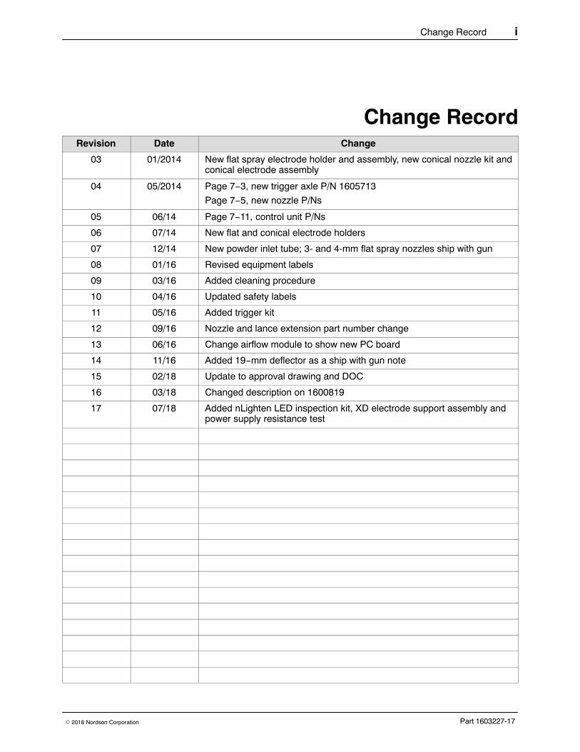
Change RecordRevision Date Change
03 01/2014 New flat spray electrode holder and assembly, new conical nozzle kit andconical electrode assembly
04 05/2014 Page 7−3, new trigger axle P/N 1605713
Page 7−5, new nozzle P/Ns
05 06/14 Page 7−11, control unit P/Ns
06 07/14 New flat and conical electrode holders
07 12/14 New powder inlet tube; 3- and 4-mm flat spray nozzles ship with gun
08 01/16 Revised equipment labels
09 03/16 Added cleaning procedure
10 04/16 Updated safety labels
11 05/16 Added trigger kit
12 09/16 Nozzle and lance extension part number change
13 06/16 Change airflow module to show new PC board
14 11/16 Added 19−mm deflector as a ship with gun note
15 02/18 Update to approval drawing and DOC
16 03/18 Changed description on 1600819
17 07/18 Added nLighten LED inspection kit, XD electrode support assembly andpower supply resistance test
Change Recordii
Part 1603227-17 � 2018 Nordson Corporation
Table of Contents iii
Part 1603227-17� 2018 Nordson Corporation
Table of Contents
Safety 1-1. . . . . . . . . . . . . . . . . . . . . . . . . . . . . . . . . . . . . . . . . . . . . . . . . .Introduction 1-1. . . . . . . . . . . . . . . . . . . . . . . . . . . . . . . . . . . . . . . . . . . . .Qualified Personnel 1-1. . . . . . . . . . . . . . . . . . . . . . . . . . . . . . . . . . . . . .Intended Use 1-1. . . . . . . . . . . . . . . . . . . . . . . . . . . . . . . . . . . . . . . . . . .Regulations and Approvals 1-1. . . . . . . . . . . . . . . . . . . . . . . . . . . . . . .Personal Safety 1-2. . . . . . . . . . . . . . . . . . . . . . . . . . . . . . . . . . . . . . . . .Fire Safety 1-2. . . . . . . . . . . . . . . . . . . . . . . . . . . . . . . . . . . . . . . . . . . . .Grounding 1-3. . . . . . . . . . . . . . . . . . . . . . . . . . . . . . . . . . . . . . . . . . . . . .Action in the Event of a Malfunction 1-3. . . . . . . . . . . . . . . . . . . . . . . .Disposal 1-3. . . . . . . . . . . . . . . . . . . . . . . . . . . . . . . . . . . . . . . . . . . . . . .
Description 2-1. . . . . . . . . . . . . . . . . . . . . . . . . . . . . . . . . . . . . . . . . . . . .Introduction 2-1. . . . . . . . . . . . . . . . . . . . . . . . . . . . . . . . . . . . . . . . . . . . .
Mobile System Components 2-2. . . . . . . . . . . . . . . . . . . . . . . . . . . .Rail-Mount System Components 2-2. . . . . . . . . . . . . . . . . . . . . . . .Wall-Mount System Components 2-2. . . . . . . . . . . . . . . . . . . . . . . .
Specifications 2-3. . . . . . . . . . . . . . . . . . . . . . . . . . . . . . . . . . . . . . . . . . .Mobile System with VBF 2-3. . . . . . . . . . . . . . . . . . . . . . . . . . . . . . .Mobile System with 50 lb. Feed Hopper 2-3. . . . . . . . . . . . . . . . . .Mobile System with 25 lb. Feed Hopper 2-3. . . . . . . . . . . . . . . . . .
Equipment Labels 2-4. . . . . . . . . . . . . . . . . . . . . . . . . . . . . . . . . . . . . . .Applicator Certification Label 2-4. . . . . . . . . . . . . . . . . . . . . . . . . . .Spray Gun Interface Controller Certification Label 2-4. . . . . . . . .Power Unit Certification Label 2-4. . . . . . . . . . . . . . . . . . . . . . . . . .Powder Spray Gun Certification Label 2-5. . . . . . . . . . . . . . . . . . . .
Table of Contentsiv
Part 1603227-17 � 2018 Nordson Corporation
System Setup 3-1. . . . . . . . . . . . . . . . . . . . . . . . . . . . . . . . . . . . . . . . . .Wall/Rail Mount Systems 3-1. . . . . . . . . . . . . . . . . . . . . . . . . . . . . . . . .
Controller Wall Mount 3-1. . . . . . . . . . . . . . . . . . . . . . . . . . . . . . . . . .Controller Rail Mount 3-2. . . . . . . . . . . . . . . . . . . . . . . . . . . . . . . . . .Interconnect Cable Connection 3-3. . . . . . . . . . . . . . . . . . . . . . . . .
System Connections 3-4. . . . . . . . . . . . . . . . . . . . . . . . . . . . . . . . . . . . .System Diagram 3-4. . . . . . . . . . . . . . . . . . . . . . . . . . . . . . . . . . . . . .Controller Connections 3-5. . . . . . . . . . . . . . . . . . . . . . . . . . . . . . . .
VBF System Setup 3-6. . . . . . . . . . . . . . . . . . . . . . . . . . . . . . . . . . . . . .Pickup Tube and Pump Installation 3-6. . . . . . . . . . . . . . . . . . . . . .
Hopper and Wall/Rail Mount System Setup 3-7. . . . . . . . . . . . . . . . .Hopper Installation − Mobile Systems 3-7. . . . . . . . . . . . . . . . . . . .Wall/Rail Mount System Hopper Installation 3-8. . . . . . . . . . . . . .Pump Mounting − Feed Hoppers 3-8. . . . . . . . . . . . . . . . . . . . . . . .
Adapter Installation 3-8. . . . . . . . . . . . . . . . . . . . . . . . . . . . . . . . .Coupling Installation 3-8. . . . . . . . . . . . . . . . . . . . . . . . . . . . . . . .
Pump Connections 3-9. . . . . . . . . . . . . . . . . . . . . . . . . . . . . . . . . . . .Wall/Rail Mount Power Unit Connections 3-10. . . . . . . . . . . . . . . . .
Spray Gun Connections 3-10. . . . . . . . . . . . . . . . . . . . . . . . . . . . . . . . . .Gun Cable 3-10. . . . . . . . . . . . . . . . . . . . . . . . . . . . . . . . . . . . . . . . . . .Air Tubing and Powder Hose 3-11. . . . . . . . . . . . . . . . . . . . . . . . . . .Bundling Tubing and Cable 3-11. . . . . . . . . . . . . . . . . . . . . . . . . . . . .
System Air and Electrical Connections 3-12. . . . . . . . . . . . . . . . . . . . .Mobile System Air Supply 3-12. . . . . . . . . . . . . . . . . . . . . . . . . . . . . .Wall / Rail Mount System Air Supply 3-13. . . . . . . . . . . . . . . . . . . . .Electrical Connections 3-14. . . . . . . . . . . . . . . . . . . . . . . . . . . . . . . . .
System Ground 3-14. . . . . . . . . . . . . . . . . . . . . . . . . . . . . . . . . . . . . . . . .Mobile Systems 3-14. . . . . . . . . . . . . . . . . . . . . . . . . . . . . . . . . . . . . . .Wall / Rail Mount Systems 3-14. . . . . . . . . . . . . . . . . . . . . . . . . . . . .
Table of Contents v
Part 1603227-17� 2018 Nordson Corporation
Operation 4-1. . . . . . . . . . . . . . . . . . . . . . . . . . . . . . . . . . . . . . . . . . . . . .European Union, ATEX, Special Conditions for Safe Use 4-1. . . . . .VBF Powder Box Installation 4-1. . . . . . . . . . . . . . . . . . . . . . . . . . . . . .Feed Hopper Filling 4-2. . . . . . . . . . . . . . . . . . . . . . . . . . . . . . . . . . . . . .Spray Gun Operation 4-3. . . . . . . . . . . . . . . . . . . . . . . . . . . . . . . . . . . .
Changing Presets with the Settings Trigger 4-3. . . . . . . . . . . . . . .Changing Powder Flow with the Settings Trigger 4-3. . . . . . . . . .Purging the Spray Gun 4-3. . . . . . . . . . . . . . . . . . . . . . . . . . . . . . . .
Fluidizing Air Operation 4-4. . . . . . . . . . . . . . . . . . . . . . . . . . . . . . . . . .Powder Feed Hopper 4-4. . . . . . . . . . . . . . . . . . . . . . . . . . . . . . . . . .Vibratory Box Feeder 4-4. . . . . . . . . . . . . . . . . . . . . . . . . . . . . . . . . .
Electrode Air Wash Operation 4-5. . . . . . . . . . . . . . . . . . . . . . . . . . . . .Daily Operation 4-5. . . . . . . . . . . . . . . . . . . . . . . . . . . . . . . . . . . . . . . . .
Initial Startup 4-5. . . . . . . . . . . . . . . . . . . . . . . . . . . . . . . . . . . . . . . . .Startup 4-5. . . . . . . . . . . . . . . . . . . . . . . . . . . . . . . . . . . . . . . . . . . . . .Standby Button 4-7. . . . . . . . . . . . . . . . . . . . . . . . . . . . . . . . . . . . . . .Factory Set Presets 4-7. . . . . . . . . . . . . . . . . . . . . . . . . . . . . . . . . . .Changing Flat Spray Nozzles 4-8. . . . . . . . . . . . . . . . . . . . . . . . . . .Changing Deflectors or Conical Nozzles 4-8. . . . . . . . . . . . . . . . . .Installing the Optional Pattern Adjuster Kit 4-9. . . . . . . . . . . . . . . .
Shutdown 4-10. . . . . . . . . . . . . . . . . . . . . . . . . . . . . . . . . . . . . . . . . . . . . . .Maintenance 4-10. . . . . . . . . . . . . . . . . . . . . . . . . . . . . . . . . . . . . . . . . . . .
Recommended Cleaning Procedure for Powder Contact Parts 4-10. . . . . . . . . . . . . . . . . . . . . . . . . . . . . . . . .Maintenance Procedures 4-11. . . . . . . . . . . . . . . . . . . . . . . . . . . . . . .
Using the Controller Interface 4-12. . . . . . . . . . . . . . . . . . . . . . . . . . . . .Interface Components 4-12. . . . . . . . . . . . . . . . . . . . . . . . . . . . . . . . .Help Codes 4-13. . . . . . . . . . . . . . . . . . . . . . . . . . . . . . . . . . . . . . . . . .Maintenance Timer, Total Hours, and Software Versions 4-13. . . .
Presets 4-14. . . . . . . . . . . . . . . . . . . . . . . . . . . . . . . . . . . . . . . . . . . . . . . .Selecting a Preset 4-14. . . . . . . . . . . . . . . . . . . . . . . . . . . . . . . . . . . .
Electrostatic Settings 4-14. . . . . . . . . . . . . . . . . . . . . . . . . . . . . . . . . . . .Select Charge� Mode 4-14. . . . . . . . . . . . . . . . . . . . . . . . . . . . . . . . .Custom Mode 4-15. . . . . . . . . . . . . . . . . . . . . . . . . . . . . . . . . . . . . . . .Classic Mode 4-16. . . . . . . . . . . . . . . . . . . . . . . . . . . . . . . . . . . . . . . . .
Classic Standard (STD) Mode 4-16. . . . . . . . . . . . . . . . . . . . . . . .Classic AFC Mode 4-16. . . . . . . . . . . . . . . . . . . . . . . . . . . . . . . . . .
Powder Flow Settings 4-17. . . . . . . . . . . . . . . . . . . . . . . . . . . . . . . . . . . .Smart Flow Mode 4-17. . . . . . . . . . . . . . . . . . . . . . . . . . . . . . . . . . . . .
Setting Smart Flow Setpoints 4-18. . . . . . . . . . . . . . . . . . . . . . . . .Smart Flow Settings − Metric Units 4-19. . . . . . . . . . . . . . . . . . . .Smart Flow Settings − English Units 4-20. . . . . . . . . . . . . . . . . . .
Classic Flow Mode Settings 4-21. . . . . . . . . . . . . . . . . . . . . . . . . . . .Controller Configuration 4-21. . . . . . . . . . . . . . . . . . . . . . . . . . . . . . . . . .
Opening the Function Menu and Making Settings 4-21. . . . . . . . . .Vibratory Box Feeder On Continuously 4-23. . . . . . . . . . . . . . . . . . .Saving and Loading Preset and Function Settings 4-23. . . . . . . . .Setting the Number of Presets 4-23. . . . . . . . . . . . . . . . . . . . . . . . . .
Table of Contentsvi
Part 1603227-17 � 2018 Nordson Corporation
Troubleshooting 5-1. . . . . . . . . . . . . . . . . . . . . . . . . . . . . . . . . . . . . . . .Help Code Troubleshooting 5-1. . . . . . . . . . . . . . . . . . . . . . . . . . . . . . .
Viewing Help Codes 5-1. . . . . . . . . . . . . . . . . . . . . . . . . . . . . . . . . . .Clearing Help Codes 5-1. . . . . . . . . . . . . . . . . . . . . . . . . . . . . . . . . .Help Code Troubleshooting Chart 5-2. . . . . . . . . . . . . . . . . . . . . . .
General Troubleshooting Chart 5-5. . . . . . . . . . . . . . . . . . . . . . . . . . . .Re-Zero Procedure 5-9. . . . . . . . . . . . . . . . . . . . . . . . . . . . . . . . . . . . . .Spray Gun Power Supply Resistance Test 5-10. . . . . . . . . . . . . . . . . .Electrode Assembly Resistance Test 5-11. . . . . . . . . . . . . . . . . . . . . . .Gun Cable Continuity Test 5-12. . . . . . . . . . . . . . . . . . . . . . . . . . . . . . . .Controller Interconnect Cable Test 5-12. . . . . . . . . . . . . . . . . . . . . . . . .System Wiring Diagrams 5-13. . . . . . . . . . . . . . . . . . . . . . . . . . . . . . . . .
Repair 6-1. . . . . . . . . . . . . . . . . . . . . . . . . . . . . . . . . . . . . . . . . . . . . . . . .Spray Gun Repair 6-1. . . . . . . . . . . . . . . . . . . . . . . . . . . . . . . . . . . . . . .
Display Module Replacement 6-2. . . . . . . . . . . . . . . . . . . . . . . . . . .Display Module Removal 6-2. . . . . . . . . . . . . . . . . . . . . . . . . . . .Display Module Installation 6-2. . . . . . . . . . . . . . . . . . . . . . . . . . .
Power Supply and Powder Path Replacement 6-3. . . . . . . . . . . .Gun Disassembly 6-3. . . . . . . . . . . . . . . . . . . . . . . . . . . . . . . . . . .Power Supply Replacement 6-4. . . . . . . . . . . . . . . . . . . . . . . . . .Powder Path Replacement 6-5. . . . . . . . . . . . . . . . . . . . . . . . . . .Powder Path Installation 6-6. . . . . . . . . . . . . . . . . . . . . . . . . . . . .Gun Re-Assembly 6-6. . . . . . . . . . . . . . . . . . . . . . . . . . . . . . . . . .
Cable Replacement 6-7. . . . . . . . . . . . . . . . . . . . . . . . . . . . . . . . . . .Cable Removal 6-7. . . . . . . . . . . . . . . . . . . . . . . . . . . . . . . . . . . . .Cable Installation 6-8. . . . . . . . . . . . . . . . . . . . . . . . . . . . . . . . . . .
Trigger Switch Replacement 6-8. . . . . . . . . . . . . . . . . . . . . . . . . . . .Switch Removal 6-8. . . . . . . . . . . . . . . . . . . . . . . . . . . . . . . . . . . .Switch Installation 6-9. . . . . . . . . . . . . . . . . . . . . . . . . . . . . . . . . .
Interface Module Repair 6-10. . . . . . . . . . . . . . . . . . . . . . . . . . . . . . . . . .Power Unit Repair 6-11. . . . . . . . . . . . . . . . . . . . . . . . . . . . . . . . . . . . . . .
Removing the Sub-Panel 6-11. . . . . . . . . . . . . . . . . . . . . . . . . . . . . .Sub-Panel Components 6-12. . . . . . . . . . . . . . . . . . . . . . . . . . . . . . . .Regulator Adjustment 6-12. . . . . . . . . . . . . . . . . . . . . . . . . . . . . . . . .iFlow Module Repair 6-14. . . . . . . . . . . . . . . . . . . . . . . . . . . . . . . . . . .
Testing iFlow Modules 6-14. . . . . . . . . . . . . . . . . . . . . . . . . . . . . . .Solenoid Valve Replacement 6-16. . . . . . . . . . . . . . . . . . . . . . . . .Proportional Valve Cleaning 6-16. . . . . . . . . . . . . . . . . . . . . . . . . .Proportional Valve Replacement 6-18. . . . . . . . . . . . . . . . . . . . . .
Vibrator Motor Replacement 6-18. . . . . . . . . . . . . . . . . . . . . . . . . . . . . .
Table of Contents vii
Part 1603227-17� 2018 Nordson Corporation
Parts 7-1. . . . . . . . . . . . . . . . . . . . . . . . . . . . . . . . . . . . . . . . . . . . . . . . . . .Introduction 7-1. . . . . . . . . . . . . . . . . . . . . . . . . . . . . . . . . . . . . . . . . . . . .System Part Numbers 7-1. . . . . . . . . . . . . . . . . . . . . . . . . . . . . . . . . . .Spray Gun Parts 7-2. . . . . . . . . . . . . . . . . . . . . . . . . . . . . . . . . . . . . . . .
Spray Gun Parts List 7-3. . . . . . . . . . . . . . . . . . . . . . . . . . . . . . . . . .Spray Gun Options 7-5. . . . . . . . . . . . . . . . . . . . . . . . . . . . . . . . . . . . .
Miscellaneous Spray Gun Options 7-5. . . . . . . . . . . . . . . . . . . . . . .nLighten� 7-5. . . . . . . . . . . . . . . . . . . . . . . . . . . . . . . . . . . . . . . . . . . .Flat Spray Nozzles 7-6. . . . . . . . . . . . . . . . . . . . . . . . . . . . . . . . . . . .Cross-Cut Nozzles 7-6. . . . . . . . . . . . . . . . . . . . . . . . . . . . . . . . . . . .45-Degree Corner-Spray Nozzle 7-7. . . . . . . . . . . . . . . . . . . . . . . . .45-Degree In-Line Flat-Spray Nozzle 7-7. . . . . . . . . . . . . . . . . . . .Conical Nozzle, Deflectors and Electrode Assembly Parts 7-8. . .
Conical Nozzle and Deflectors 7-8. . . . . . . . . . . . . . . . . . . . . . . .Conical Nozzle Kit 7-8. . . . . . . . . . . . . . . . . . . . . . . . . . . . . . . . . . .Conical Electrode Assembly 7-9. . . . . . . . . . . . . . . . . . . . . . . . . .
XD Electrode Support 7-9. . . . . . . . . . . . . . . . . . . . . . . . . . . . . . . . . .Pattern Adjuster Kit 7-10. . . . . . . . . . . . . . . . . . . . . . . . . . . . . . . . . . .Lance Extensions 7-10. . . . . . . . . . . . . . . . . . . . . . . . . . . . . . . . . . . . .Pattern Adjuster Kit for Lance Extensions 7-10. . . . . . . . . . . . . . . .Ion Collector Kit 7-11. . . . . . . . . . . . . . . . . . . . . . . . . . . . . . . . . . . . . . .Ion Collector Components for Lance Extensions 7-11. . . . . . . . . .
Controller Parts 7-12. . . . . . . . . . . . . . . . . . . . . . . . . . . . . . . . . . . . . . . . .Interface Parts 7-12. . . . . . . . . . . . . . . . . . . . . . . . . . . . . . . . . . . . . . . .Interface Parts List 7-13. . . . . . . . . . . . . . . . . . . . . . . . . . . . . . . . . . . .Power Unit Parts 7-14. . . . . . . . . . . . . . . . . . . . . . . . . . . . . . . . . . . . . .Power Unit Parts List 7-15. . . . . . . . . . . . . . . . . . . . . . . . . . . . . . . . . .iFlow Module Parts 7-16. . . . . . . . . . . . . . . . . . . . . . . . . . . . . . . . . . . .
System Components and Parts 7-17. . . . . . . . . . . . . . . . . . . . . . . . . . .Mobile System Parts 7-17. . . . . . . . . . . . . . . . . . . . . . . . . . . . . . . . . .Wall/Rail Mount System Parts 7-18. . . . . . . . . . . . . . . . . . . . . . . . . .Powder Hose and Air Tubing Parts 7-18. . . . . . . . . . . . . . . . . . . . . . .Miscellaneous Options 7-19. . . . . . . . . . . . . . . . . . . . . . . . . . . . . . . . .
Cup Gun 7-19. . . . . . . . . . . . . . . . . . . . . . . . . . . . . . . . . . . . . . . . . .Pump Parts 7-20. . . . . . . . . . . . . . . . . . . . . . . . . . . . . . . . . . . . . . . . . .Coupling and Pump Adapter Kit 7-20. . . . . . . . . . . . . . . . . . . . . . . . .

Safety 1-1
Part 1603227-17� 2018 Nordson Corporation
Section 1Safety
Introduction Read and follow these safety instructions. Task- and equipment-specificwarnings, cautions, and instructions are included in equipmentdocumentation where appropriate.
Make sure all equipment documentation, including these instructions, isaccessible to all persons operating or servicing equipment.
Qualified Personnel Equipment owners are responsible for making sure that Nordson equipmentis installed, operated, and serviced by qualified personnel. Qualifiedpersonnel are those employees or contractors who are trained to safelyperform their assigned tasks. They are familiar with all relevant safety rulesand regulations and are physically capable of performing their assignedtasks.
Intended Use Use of Nordson equipment in ways other than those described in thedocumentation supplied with the equipment may result in injury to personsor damage to property.
Some examples of unintended use of equipment include
� using incompatible materials
� making unauthorized modifications
� removing or bypassing safety guards or interlocks
� using incompatible or damaged parts
� using unapproved auxiliary equipment
� operating equipment in excess of maximum ratings
Regulations and Approvals Make sure all equipment is rated and approved for the environment in whichit is used. Any approvals obtained for Nordson equipment will be voided ifinstructions for installation, operation, and service are not followed.
All phases of equipment installation must comply with all federal, state, andlocal codes.
Safety1-2
Part 1603227-17 � 2018 Nordson Corporation
Personal Safety To prevent injury follow these instructions.
� Do not operate or service equipment unless you are qualified.
� Do not operate equipment unless safety guards, doors, or covers areintact and automatic interlocks are operating properly. Do not bypass ordisarm any safety devices.
� Keep clear of moving equipment. Before adjusting or servicing anymoving equipment, shut off the power supply and wait until theequipment comes to a complete stop. Lock out power and secure theequipment to prevent unexpected movement.
� Relieve (bleed off) hydraulic and pneumatic pressure before adjusting orservicing pressurized systems or components. Disconnect, lock out, andtag switches before servicing electrical equipment.
� Obtain and read Safety Data Sheets (SDS) for all materials used. Followthe manufacturer’s instructions for safe handling and use of materials,and use recommended personal protection devices.
� To prevent injury, be aware of less-obvious dangers in the workplacethat often cannot be completely eliminated, such as hot surfaces, sharpedges, energized electrical circuits, and moving parts that cannot beenclosed or otherwise guarded for practical reasons.
Fire Safety To avoid a fire or explosion, follow these instructions.
� Do not smoke, weld, grind, or use open flames where flammablematerials are being used or stored.
� Provide adequate ventilation to prevent dangerous concentrations ofvolatile materials or vapors. Refer to local codes or your material SDSfor guidance.
� Do not disconnect live electrical circuits while working with flammablematerials. Shut off power at a disconnect switch first to prevent sparking.
� Know where emergency stop buttons, shutoff valves, and fireextinguishers are located. If a fire starts in a spray booth, immediatelyshut off the spray system and exhaust fans.
� Clean, maintain, test, and repair equipment according to the instructionsin your equipment documentation.
� Use only replacement parts that are designed for use with originalequipment. Contact your Nordson representative for parts informationand advice.
Safety 1-3
Part 1603227-17� 2018 Nordson Corporation
Grounding WARNING: Operating faulty electrostatic equipment is hazardous and cancause electrocution, fire, or explosion. Make resistance checks part of yourperiodic maintenance program. If you receive even a slight electrical shockor notice static sparking or arcing, shut down all electrical or electrostaticequipment immediately. Do not restart the equipment until the problem hasbeen identified and corrected.
Grounding inside and around the booth openings must comply with NFPArequirements for Class II, Division 1 or 2 Hazardous Locations. Refer toNFPA 33, NFPA 70 (NEC articles 500, 502, and 516), and NFPA 77, latestconditions.
� All electrically conductive objects in the spray areas shall be electricallyconnected to ground with a resistance of not more than 1 megohm asmeasured with an instrument that applies at least 500 volts to the circuitbeing evaluated.
� Equipment to be grounded includes, but is not limited to, the floor of thespray area, operator platforms, hoppers, photoeye supports, andblow-off nozzles. Personnel working in the spray area must begrounded.
� There is a possible ignition potential from the charged human body.Personnel standing on a painted surface, such as an operator platform,or wearing non-conductive shoes, are not grounded. Personnel mustwear shoes with conductive soles or use a ground strap to maintain aconnection to ground when working with or around electrostaticequipment.
� Operators must maintain skin-to-handle contact between their hand andthe gun handle to prevent shocks while operating manual electrostaticspray guns. If gloves must be worn, cut away the palm or fingers, wearelectrically conductive gloves, or wear a grounding strap connected tothe gun handle or other true earth ground.
� Shut off electrostatic power supplies and ground gun electrodes beforemaking adjustments or cleaning powder spray guns.
� Connect all disconnected equipment, ground cables, and wires afterservicing equipment.
Action in the Event of a Malfunction If a system or any equipment in a system malfunctions, shut off the systemimmediately and perform the following steps:
� Disconnect and lock out electrical power. Close pneumatic shutoffvalves and relieve pressures.
� Identify the reason for the malfunction and correct it before restarting theequipment.
Disposal Dispose of equipment and materials used in operation and servicingaccording to local codes.
Safety1-4
Part 1603227-17 � 2018 Nordson Corporation
Description 2-1
Part 1603227-17� 2018 Nordson Corporation
Section 2Description
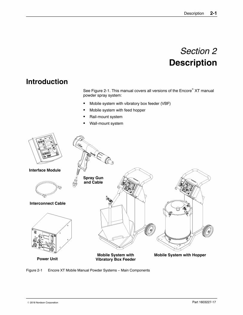
Introduction See Figure 2-1. This manual covers all versions of the Encore� XT manualpowder spray system:
� Mobile system with vibratory box feeder (VBF)
� Mobile system with feed hopper
� Rail-mount system
� Wall-mount system
Mobile System with HopperMobile System withVibratory Box Feeder
Spray Gunand Cable
Interface Module
Interconnect Cable
Power Unit
Figure 2-1 Encore XT Mobile Manual Powder Systems − Main Components
Description2-2
Part 1603227-17 � 2018 Nordson Corporation
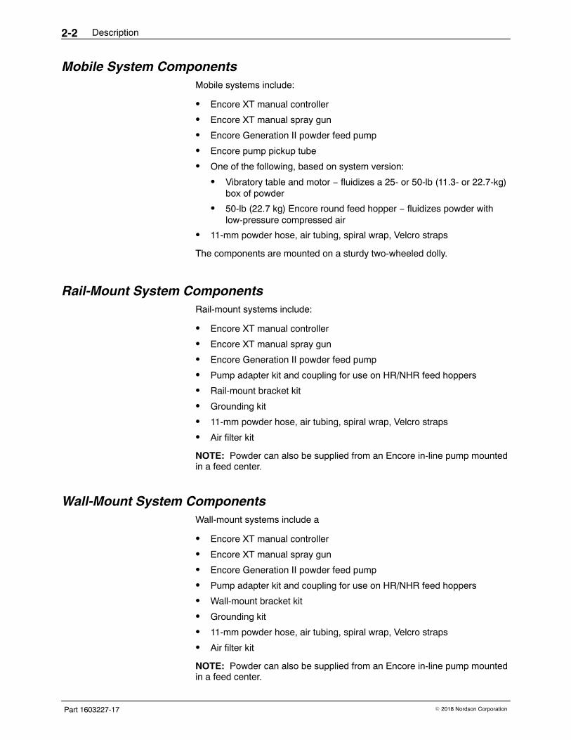
Mobile System Components Mobile systems include:
� Encore XT manual controller
� Encore XT manual spray gun
� Encore Generation II powder feed pump
� Encore pump pickup tube
� One of the following, based on system version:
� Vibratory table and motor − fluidizes a 25- or 50-lb (11.3- or 22.7-kg)box of powder
� 50-lb (22.7 kg) Encore round feed hopper − fluidizes powder withlow-pressure compressed air
� 11-mm powder hose, air tubing, spiral wrap, Velcro straps
The components are mounted on a sturdy two-wheeled dolly.
Rail-Mount System Components Rail-mount systems include:
� Encore XT manual controller
� Encore XT manual spray gun
� Encore Generation II powder feed pump
� Pump adapter kit and coupling for use on HR/NHR feed hoppers
� Rail-mount bracket kit
� Grounding kit
� 11-mm powder hose, air tubing, spiral wrap, Velcro straps
� Air filter kit
NOTE: Powder can also be supplied from an Encore in-line pump mountedin a feed center.
Wall-Mount System Components Wall-mount systems include a
� Encore XT manual controller
� Encore XT manual spray gun
� Encore Generation II powder feed pump
� Pump adapter kit and coupling for use on HR/NHR feed hoppers
� Wall-mount bracket kit
� Grounding kit
� 11-mm powder hose, air tubing, spiral wrap, Velcro straps
� Air filter kit
NOTE: Powder can also be supplied from an Encore in-line pump mountedin a feed center.
Description 2-3
Part 1603227-17� 2018 Nordson Corporation
Specifications
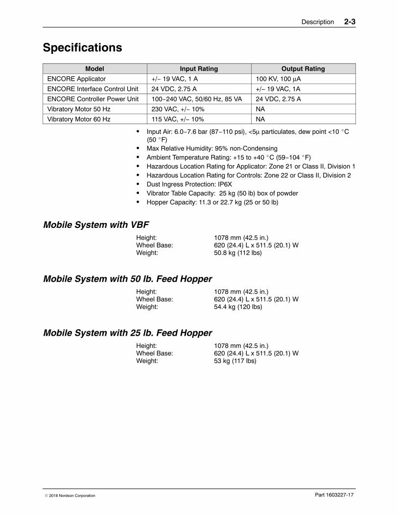
Model Input Rating Output Rating
ENCORE Applicator +/− 19 VAC, 1 A 100 KV, 100 μA
ENCORE Interface Control Unit 24 VDC, 2.75 A +/− 19 VAC, 1A
ENCORE Controller Power Unit 100−240 VAC, 50/60 Hz, 85 VA 24 VDC, 2.75 A
Vibratory Motor 50 Hz 230 VAC, +/− 10% NA
Vibratory Motor 60 Hz 115 VAC, +/− 10% NA
� Input Air: 6.0−7.6 bar (87−110 psi), <5μ particulates, dew point <10 �C(50 �F)
� Max Relative Humidity: 95% non-Condensing� Ambient Temperature Rating: +15 to +40 �C (59−104 �F)� Hazardous Location Rating for Applicator: Zone 21 or Class II, Division 1� Hazardous Location Rating for Controls: Zone 22 or Class II, Division 2� Dust Ingress Protection: IP6X� Vibrator Table Capacity: 25 kg (50 lb) box of powder� Hopper Capacity: 11.3 or 22.7 kg (25 or 50 lb)
Mobile System with VBF Height: 1078 mm (42.5 in.)Wheel Base: 620 (24.4) L x 511.5 (20.1) WWeight: 50.8 kg (112 lbs)
Mobile System with 50 lb. Feed Hopper Height: 1078 mm (42.5 in.)Wheel Base: 620 (24.4) L x 511.5 (20.1) WWeight: 54.4 kg (120 lbs)
Mobile System with 25 lb. Feed Hopper Height: 1078 mm (42.5 in.)Wheel Base: 620 (24.4) L x 511.5 (20.1) WWeight: 53 kg (117 lbs)
Description2-4
Part 1603227-17 � 2018 Nordson Corporation
Equipment Labels
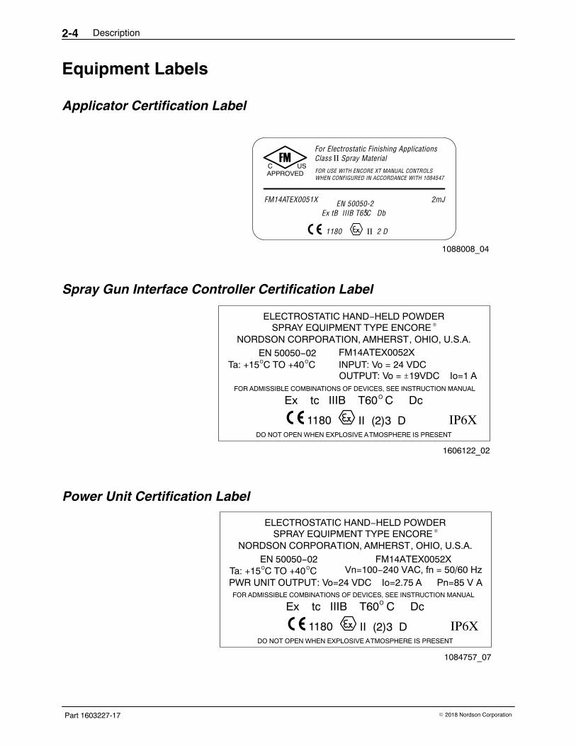
Applicator Certification Label
FM
APPROVEDC US
For Electrostatic Finishing ApplicationsClass II Spray Material
FOR USE WITH ENCORE XT MANUAL CONTROLSWHEN CONFIGURED IN ACCORDANCE WITH 1084547
FM14ATEX0051X 2mJEN 50050-20Ex tB IIIB T65C Db
1180 II 2 D
1088008_04
Spray Gun Interface Controller Certification Label
ELECTROSTATIC HAND−HELD POWDER®SPRAY EQUIPMENT TYPE ENCORE
NORDSON CORPORATION, AMHERST, OHIO, U.S.A.EN 50050−02O OTa: +15 C TO +40 C
OUTPUT: Vo = 19VDC Io=1 A
FM14ATEX0052XINPUT: Vo = 24 VDC
FOR ADMISSIBLE COMBINATIONS OF DEVICES, SEE INSTRUCTION MANUALOEx tc IIIB T60 C Dc
1180 II (2)3 D IP6XDO NOT OPEN WHEN EXPLOSIVE ATMOSPHERE IS PRESENT
±
1606122_02
Power Unit Certification Label
ELECTROSTATIC HAND−HELD POWDER®SPRAY EQUIPMENT TYPE ENCORE
NORDSON CORPORATION, AMHERST, OHIO, U.S.A.EN 50050−02O OTa: +15 C TO +40 C
PWR UNIT OUTPUT: Vo=24 VDC Io=2.75 A Pn=85 V A
FM14ATEX0052XVn=100−240 VAC, fn = 50/60 Hz
FOR ADMISSIBLE COMBINATIONS OF DEVICES, SEE INSTRUCTION MANUALOEx tc IIIB T60 C Dc
1180 II (2)3 D IP6XDO NOT OPEN WHEN EXPLOSIVE ATMOSPHERE IS PRESENT
1084757_07
Description 2-5
Part 1603227-17� 2018 Nordson Corporation
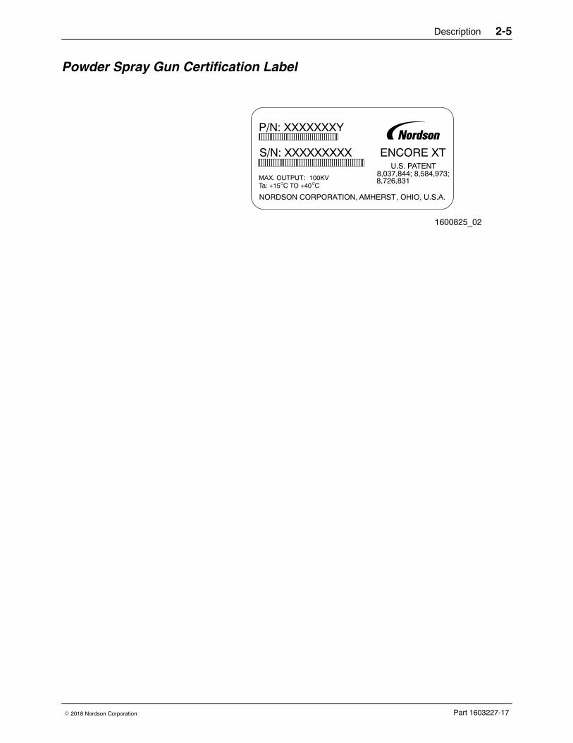
Powder Spray Gun Certification Label
ENCORE XTU.S. PATENT
8,037,844; 8,584,973;8,726,831
NORDSON CORPORATION, AMHERST, OHIO, U.S.A.
P/N: XXXXXXXY
S/N: XXXXXXXXX
MAX. OUTPUT: 100KVO OTa: +15 C TO +40 C
1600825_02

Description2-6
Part 1603227-17 � 2018 Nordson Corporation
System Setup 3-1
Part 1603227-17� 2018 Nordson Corporation
Section 3System Setup
Wall/Rail Mount Systems
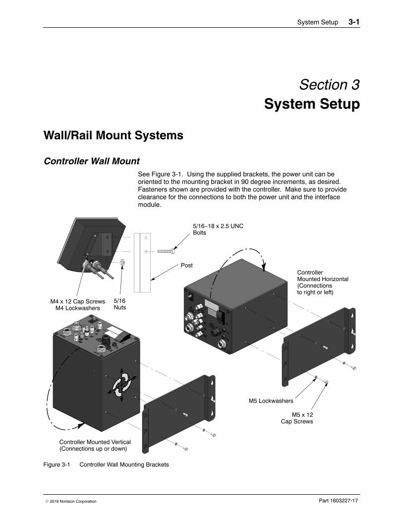
Controller Wall Mount See Figure 3-1. Using the supplied brackets, the power unit can beoriented to the mounting bracket in 90 degree increments, as desired.Fasteners shown are provided with the controller. Make sure to provideclearance for the connections to both the power unit and the interfacemodule.
ControllerMounted Horizontal(Connectionsto right or left)
Controller Mounted Vertical(Connections up or down)
5/16Nuts
5/16−18 x 2.5 UNCBolts
M4 x 12 Cap ScrewsM4 Lockwashers
M5 x 12Cap Screws
M5 Lockwashers
Post
Figure 3-1 Controller Wall Mounting Brackets
System Setup3-2
Part 1603227-17 � 2018 Nordson Corporation
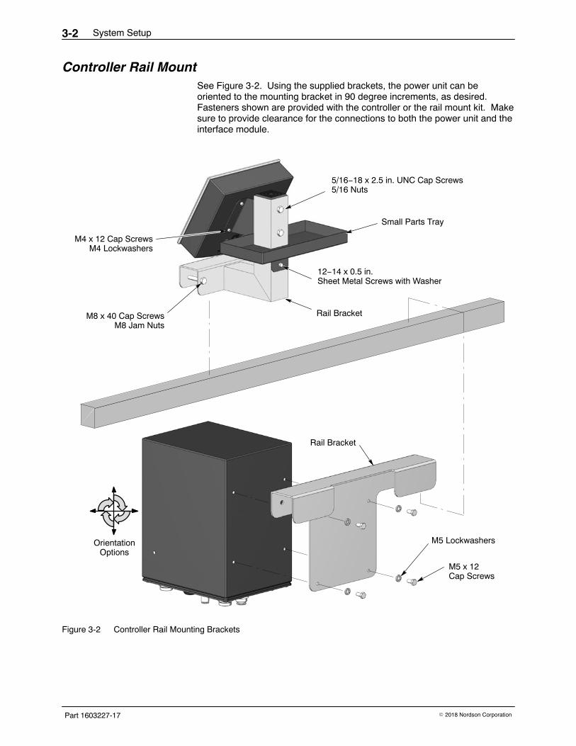
Controller Rail Mount See Figure 3-2. Using the supplied brackets, the power unit can beoriented to the mounting bracket in 90 degree increments, as desired.Fasteners shown are provided with the controller or the rail mount kit. Makesure to provide clearance for the connections to both the power unit and theinterface module.
M5 x 12Cap Screws
M5 Lockwashers
Rail Bracket
M8 x 40 Cap ScrewsM8 Jam Nuts
Rail Bracket
12−14 x 0.5 in.Sheet Metal Screws with Washer
Small Parts Tray
5/16−18 x 2.5 in. UNC Cap Screws5/16 Nuts
OrientationOptions
M4 x 12 Cap ScrewsM4 Lockwashers
Figure 3-2 Controller Rail Mounting Brackets
System Setup 3-3
Part 1603227-17� 2018 Nordson Corporation
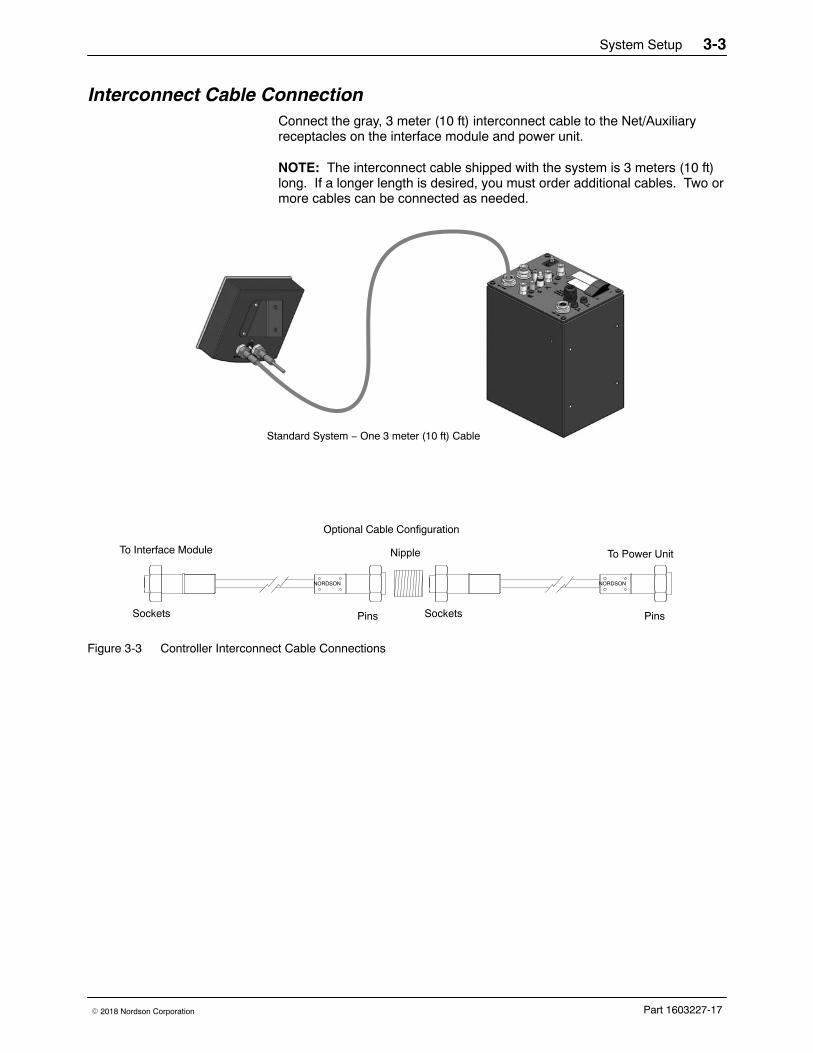
Interconnect Cable Connection Connect the gray, 3 meter (10 ft) interconnect cable to the Net/Auxiliaryreceptacles on the interface module and power unit.
NOTE: The interconnect cable shipped with the system is 3 meters (10 ft)long. If a longer length is desired, you must order additional cables. Two ormore cables can be connected as needed.
NORDSON
PinsSockets
NORDSON
SocketsPins
Nipple To Power UnitTo Interface Module
Standard System − One 3 meter (10 ft) Cable
Optional Cable Configuration
Figure 3-3 Controller Interconnect Cable Connections
System Setup3-4
Part 1603227-17 � 2018 Nordson Corporation
System Connections
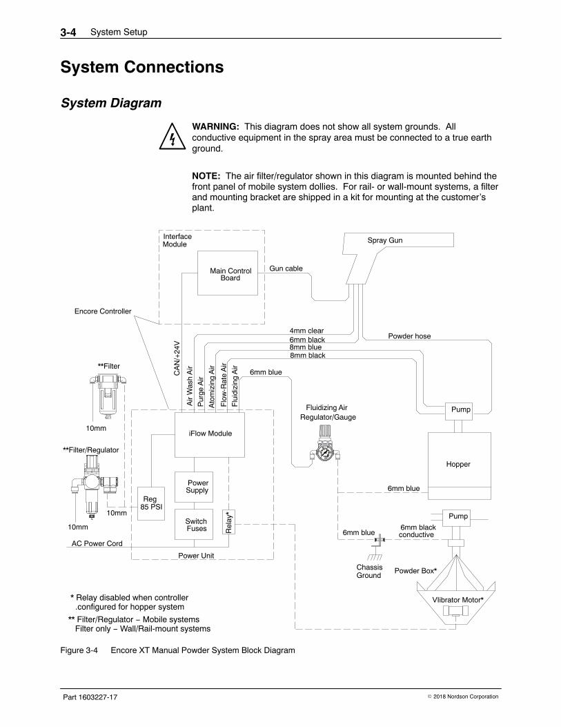
System Diagram
WARNING: This diagram does not show all system grounds. Allconductive equipment in the spray area must be connected to a true earthground.
NOTE: The air filter/regulator shown in this diagram is mounted behind thefront panel of mobile system dollies. For rail- or wall-mount systems, a filterand mounting bracket are shipped in a kit for mounting at the customer’splant.
Pur
ge A
ir
Reg85 PSI
SwitchFuses R
elay
*
PowerSupply
AC Power Cord
Flu
idiz
ing
Air
Main Control
iFlow Module
CA
N/+
24V
Air
Was
h A
ir
Ato
miz
ing
Air
Flo
w-R
ate
Air
Gun cable
Fluidizing Air
6mm black4mm clear
8mm blue8mm black
6mm blue
Power Unit
InterfaceModule
Hopper
Pump
Spray Gun
Powder hose
6mm blue
Board
* Relay disabled when controller .configured for hopper system
** Filter/Regulator − Mobile systems Filter only − Wall/Rail-mount systems
10mm
**Filter/Regulator
10mm
Encore Controller
8020
psiBAR
10
0
67
100
40
23
60
54
VIibrator Motor*
Powder Box*
Pump
Regulator/Gauge
6mm blackconductive6mm blue
Chassis Ground
**Filter
10mm
Figure 3-4 Encore XT Manual Powder System Block Diagram
System Setup 3-5
Part 1603227-17� 2018 Nordson Corporation
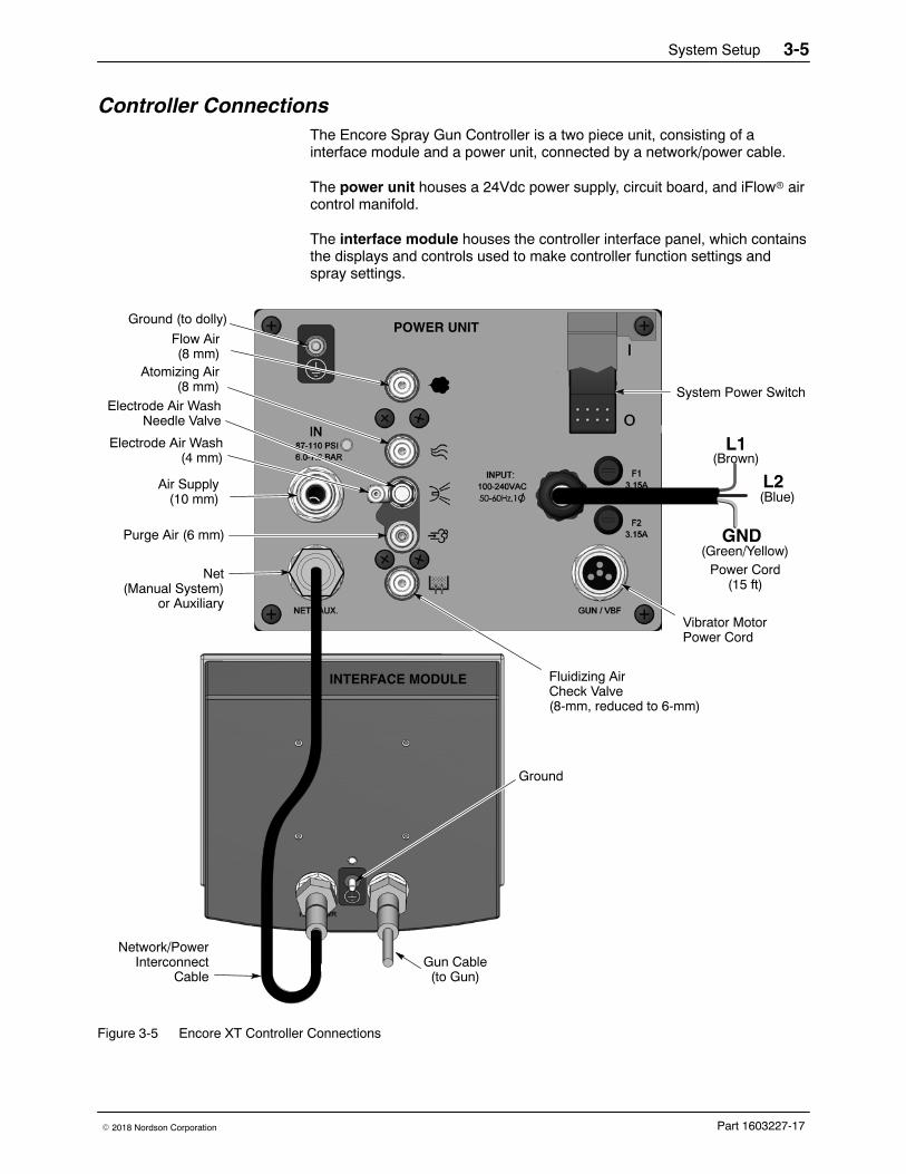
Controller Connections The Encore Spray Gun Controller is a two piece unit, consisting of ainterface module and a power unit, connected by a network/power cable.
The power unit houses a 24Vdc power supply, circuit board, and iFlow� aircontrol manifold.
The interface module houses the controller interface panel, which containsthe displays and controls used to make controller function settings andspray settings.
L1
L2
GND
System Power Switch
Fluidizing AirCheck Valve(8-mm, reduced to 6-mm)
Vibrator MotorPower Cord
Air Supply(10 mm)
Electrode Air Wash(4 mm)
Electrode Air WashNeedle Valve
Atomizing Air(8 mm)
Flow Air(8 mm)
Ground (to dolly)
Power Cord(15 ft)
Gun Cable(to Gun)
Ground
Network/PowerInterconnect
Cable
POWER UNIT
INTERFACE MODULE
(Brown)
(Blue)
(Green/Yellow)Purge Air (6 mm)
Net(Manual System)
or Auxiliary
Figure 3-5 Encore XT Controller Connections
System Setup3-6
Part 1603227-17 � 2018 Nordson Corporation
VBF System Setup
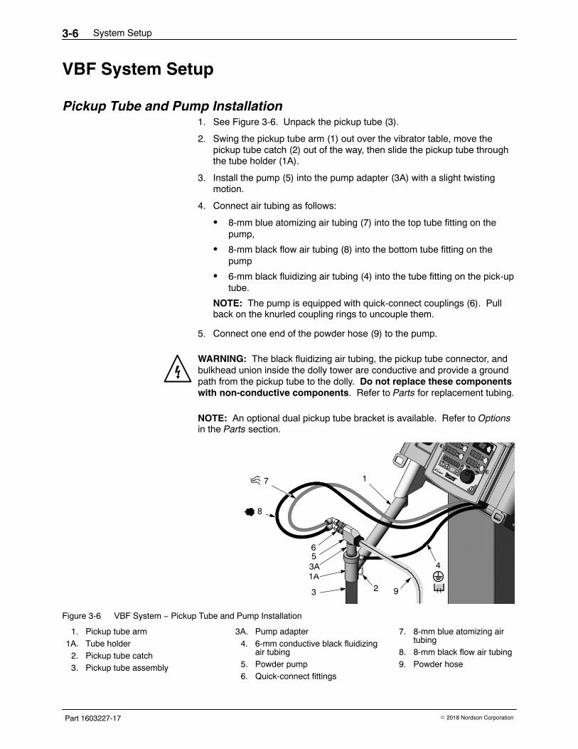
Pickup Tube and Pump Installation 1. See Figure 3-6. Unpack the pickup tube (3).
2. Swing the pickup tube arm (1) out over the vibrator table, move thepickup tube catch (2) out of the way, then slide the pickup tube throughthe tube holder (1A).
3. Install the pump (5) into the pump adapter (3A) with a slight twistingmotion.
4. Connect air tubing as follows:
� 8-mm blue atomizing air tubing (7) into the top tube fitting on thepump,
� 8-mm black flow air tubing (8) into the bottom tube fitting on thepump
� 6-mm black fluidizing air tubing (4) into the tube fitting on the pick-uptube.
NOTE: The pump is equipped with quick-connect couplings (6). Pullback on the knurled coupling rings to uncouple them.
5. Connect one end of the powder hose (9) to the pump.
WARNING: The black fluidizing air tubing, the pickup tube connector, andbulkhead union inside the dolly tower are conductive and provide a groundpath from the pickup tube to the dolly. Do not replace these componentswith non-conductive components. Refer to Parts for replacement tubing.
NOTE: An optional dual pickup tube bracket is available. Refer to Optionsin the Parts section.
7
8
4
65
1
3 21A3A
9
Figure 3-6 VBF System − Pickup Tube and Pump Installation
1. Pickup tube arm1A. Tube holder
2. Pickup tube catch3. Pickup tube assembly
3A. Pump adapter4. 6-mm conductive black fluidizing
air tubing5. Powder pump6. Quick-connect fittings
7. 8-mm blue atomizing airtubing
8. 8-mm black flow air tubing9. Powder hose
System Setup 3-7
Part 1603227-17� 2018 Nordson Corporation
Hopper and Wall/Rail Mount System Setup
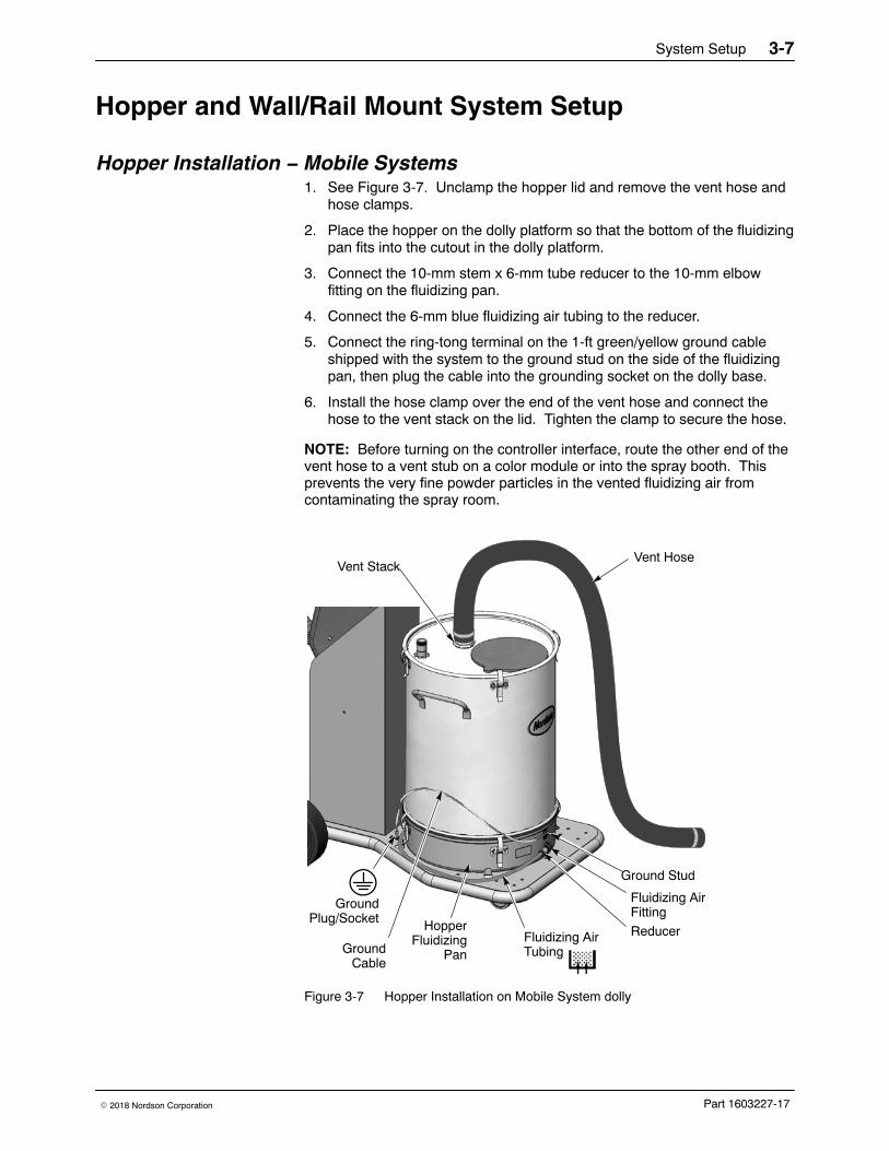
Hopper Installation − Mobile Systems 1. See Figure 3-7. Unclamp the hopper lid and remove the vent hose and
hose clamps.
2. Place the hopper on the dolly platform so that the bottom of the fluidizingpan fits into the cutout in the dolly platform.
3. Connect the 10-mm stem x 6-mm tube reducer to the 10-mm elbowfitting on the fluidizing pan.
4. Connect the 6-mm blue fluidizing air tubing to the reducer.
5. Connect the ring-tong terminal on the 1-ft green/yellow ground cableshipped with the system to the ground stud on the side of the fluidizingpan, then plug the cable into the grounding socket on the dolly base.
6. Install the hose clamp over the end of the vent hose and connect thehose to the vent stack on the lid. Tighten the clamp to secure the hose.
NOTE: Before turning on the controller interface, route the other end of thevent hose to a vent stub on a color module or into the spray booth. Thisprevents the very fine powder particles in the vented fluidizing air fromcontaminating the spray room.
Fluidizing AirTubing
Vent Stack
GroundPlug/Socket Hopper
FluidizingPan
Vent Hose
GroundCable
Fluidizing AirFitting
Ground Stud
Reducer
Figure 3-7 Hopper Installation on Mobile System dolly
System Setup3-8
Part 1603227-17 � 2018 Nordson Corporation
Wall/Rail Mount System Hopper Installation If connecting fluidizing air to a Nordson feed hopper, use the 10-mm stem x8-mm tube reducer fitting shipped with the controller to connect the 8-mmtubing supplied with the system to the hopper fluidizing air fitting.
Install a customer-supplied air regulator and gauge in the air line betweenthe power unit and the powder source to regulate the fluidizing air pressure.
Connect the vent hose shipped with the hopper to the hopper lid as shownin Figure 3-7. Route the vent hose to a vent stub on the booth or collectormodule.
Pump Mounting − Feed Hoppers
CAUTION: Pump adapter O-rings are conductive silicone, to provide aground connection between the pump body and the pickup tube or hopperlid. Do not replace these O-rings with non-conductive O-rings.
Hopper and wall/rail mount systems include an Encore pump adapter kitand a coupling, either of which can be used to install the Encore pump onthe pickup tube provided with a Nordson HR or NHR feed hopper. It isrecommended that the adapter be used rather than the coupling.
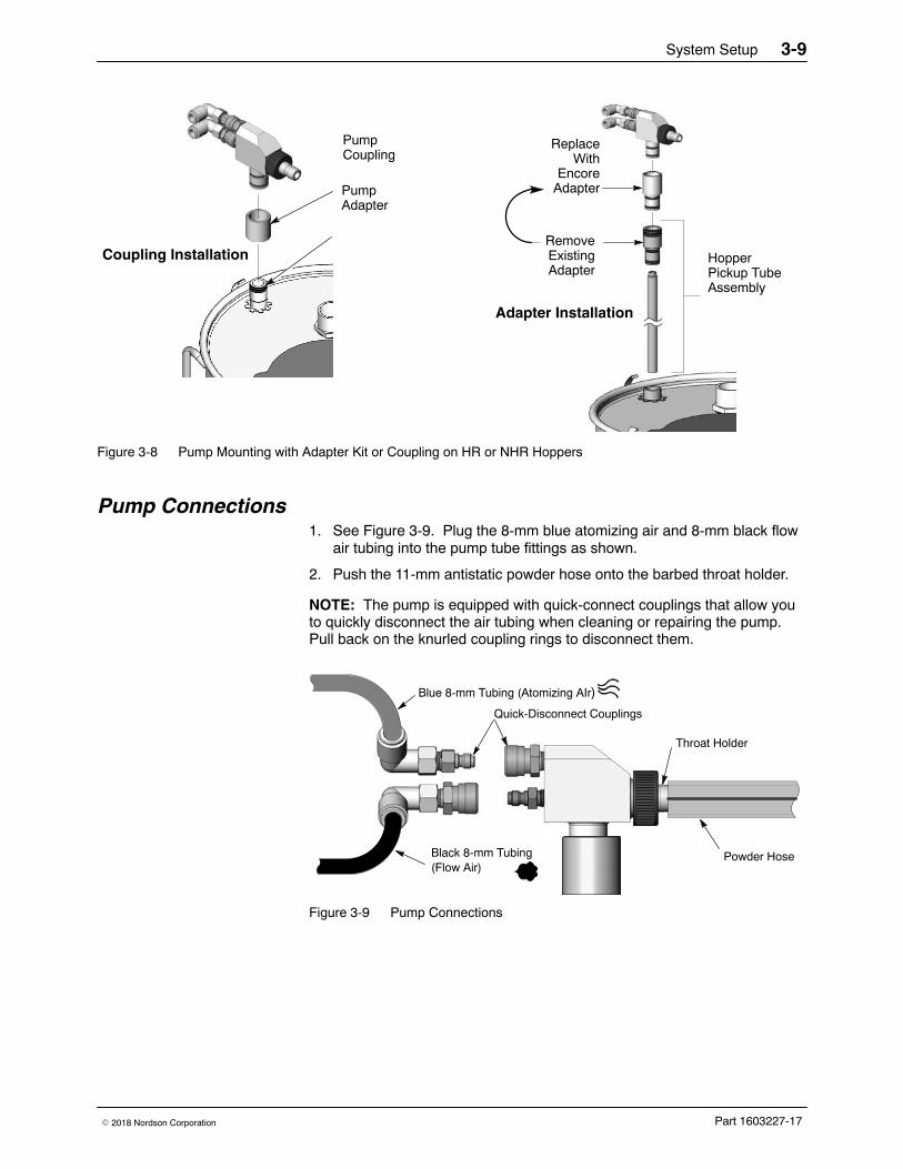
Adapter Installation Follow these steps to install the Encore pump adapter:
1. See Figure 3-8. Remove the pickup tube from the pump mount in thehopper lid, then unscrew the existing adapter from the pickup tube.
2. Screw the Encore pump adapter shipped with the system on the pickuptube.
3. Install the pump adapter and pickup tube into the pump mount, theninstall the Encore pump into the adapter with a slight twisting motion.
Coupling Installation See Figure 3-8. The coupling allows you to use the existing pump adapter.Install the pump coupling on the existing pump mount with a slight twistingmotion, then install the pump into the coupling with the same motion.
System Setup 3-9
Part 1603227-17� 2018 Nordson Corporation
HopperPickup TubeAssembly
RemoveExistingAdapter
ReplaceWith
EncoreAdapterPump
Adapter
Coupling Installation
Adapter Installation
PumpCoupling
Figure 3-8 Pump Mounting with Adapter Kit or Coupling on HR or NHR Hoppers
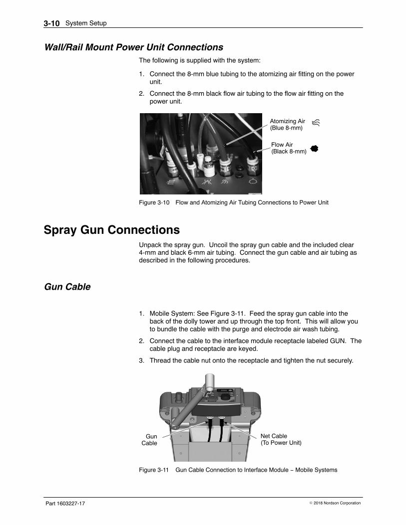
Pump Connections 1. See Figure 3-9. Plug the 8-mm blue atomizing air and 8-mm black flow
air tubing into the pump tube fittings as shown.
2. Push the 11-mm antistatic powder hose onto the barbed throat holder.
NOTE: The pump is equipped with quick-connect couplings that allow youto quickly disconnect the air tubing when cleaning or repairing the pump.Pull back on the knurled coupling rings to disconnect them.
Quick-Disconnect Couplings
Blue 8-mm Tubing (Atomizing AIr)
Black 8-mm Tubing(Flow Air)
Throat Holder
Powder Hose
Figure 3-9 Pump Connections
System Setup3-10
Part 1603227-17 � 2018 Nordson Corporation
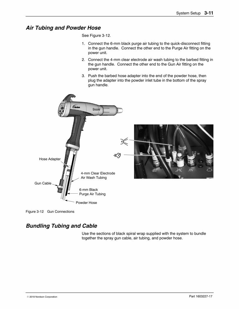
Wall/Rail Mount Power Unit Connections The following is supplied with the system:
1. Connect the 8-mm blue tubing to the atomizing air fitting on the powerunit.
2. Connect the 8-mm black flow air tubing to the flow air fitting on thepower unit.
Atomizing Air(Blue 8-mm)
Flow Air(Black 8-mm)
Figure 3-10 Flow and Atomizing Air Tubing Connections to Power Unit
Spray Gun Connections Unpack the spray gun. Uncoil the spray gun cable and the included clear4-mm and black 6-mm air tubing. Connect the gun cable and air tubing asdescribed in the following procedures.
Gun Cable
1. Mobile System: See Figure 3-11. Feed the spray gun cable into theback of the dolly tower and up through the top front. This will allow youto bundle the cable with the purge and electrode air wash tubing.
2. Connect the cable to the interface module receptacle labeled GUN. Thecable plug and receptacle are keyed.
3. Thread the cable nut onto the receptacle and tighten the nut securely.
Net Cable(To Power Unit)
GunCable
Figure 3-11 Gun Cable Connection to Interface Module − Mobile Systems
System Setup 3-11
Part 1603227-17� 2018 Nordson Corporation
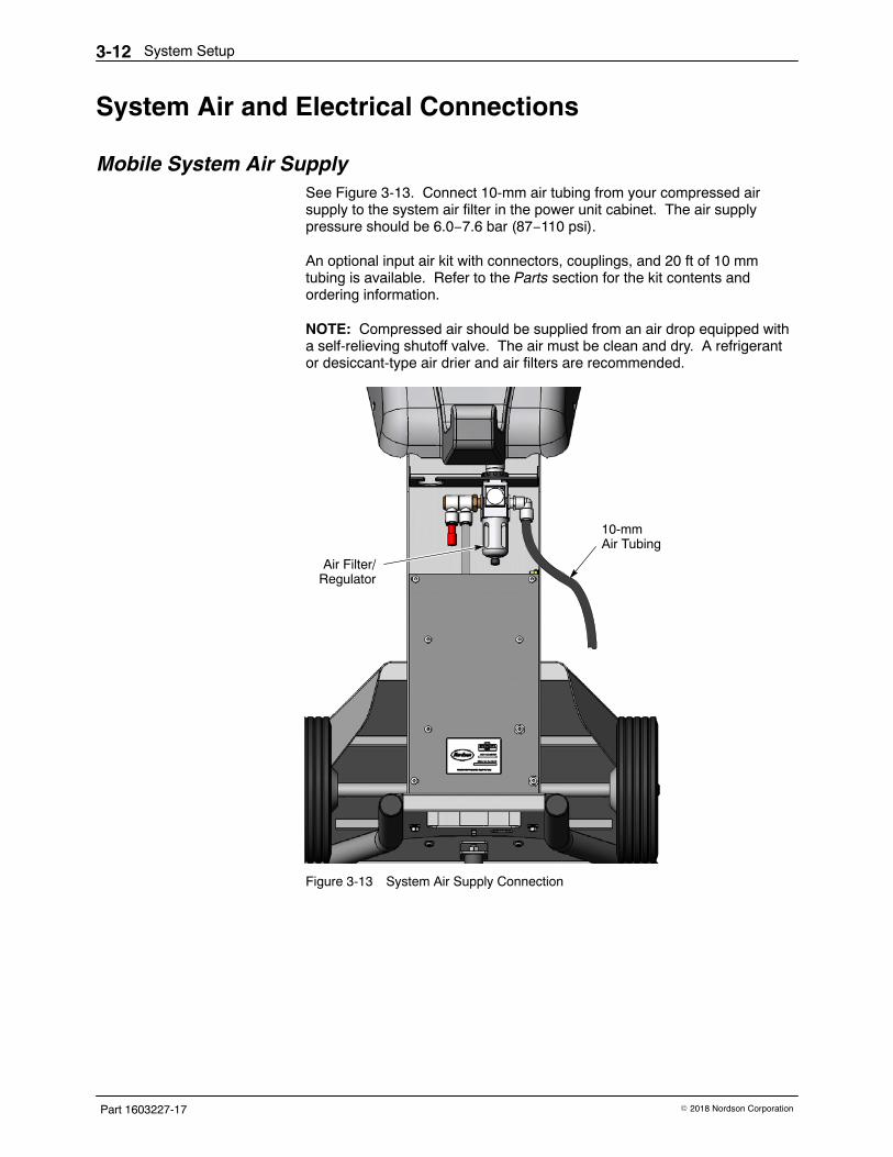
Air Tubing and Powder Hose See Figure 3-12.
1. Connect the 6-mm black purge air tubing to the quick-disconnect fittingin the gun handle. Connect the other end to the Purge Air fitting on thepower unit.
2. Connect the 4-mm clear electrode air wash tubing to the barbed fitting inthe gun handle. Connect the other end to the Gun Air fitting on thepower unit.
3. Push the barbed hose adapter into the end of the powder hose, thenplug the adapter into the powder inlet tube in the bottom of the spraygun handle.
4-mm Clear ElectrodeAir Wash Tubing
6-mm BlackPurge Air Tubing
Hose Adapter
Powder Hose
Gun Cable
Figure 3-12 Gun Connections
Bundling Tubing and Cable Use the sections of black spiral wrap supplied with the system to bundletogether the spray gun cable, air tubing, and powder hose.
System Setup3-12
Part 1603227-17 � 2018 Nordson Corporation
System Air and Electrical Connections
Mobile System Air Supply See Figure 3-13. Connect 10-mm air tubing from your compressed airsupply to the system air filter in the power unit cabinet. The air supplypressure should be 6.0−7.6 bar (87−110 psi).
An optional input air kit with connectors, couplings, and 20 ft of 10 mmtubing is available. Refer to the Parts section for the kit contents andordering information.
NOTE: Compressed air should be supplied from an air drop equipped witha self-relieving shutoff valve. The air must be clean and dry. A refrigerantor desiccant-type air drier and air filters are recommended.
10-mmAir Tubing
Air Filter/Regulator
Figure 3-13 System Air Supply Connection
System Setup 3-13
Part 1603227-17� 2018 Nordson Corporation
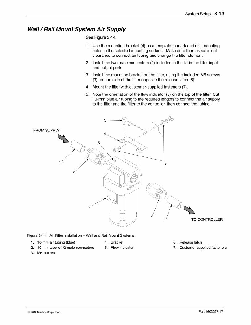
Wall / Rail Mount System Air Supply See Figure 3-14.
1. Use the mounting bracket (4) as a template to mark and drill mountingholes in the selected mounting surface. Make sure there is sufficientclearance to connect air tubing and change the filter element.
2. Install the two male connectors (2) included in the kit in the filter inputand output ports.
3. Install the mounting bracket on the filter, using the included M5 screws(3), on the side of the filter opposite the release latch (6).
4. Mount the filter with customer-supplied fasteners (7).
5. Note the orientation of the flow indicator (5) on the top of the filter. Cut10-mm blue air tubing to the required lengths to connect the air supplyto the filter and the filter to the controller, then connect the tubing.
1
12
2
3
4
6
5
7
FROM SUPPLY
TO CONTROLLER
Figure 3-14 Air Filter Installation − Wall and Rail Mount Systems
1. 10-mm air tubing (blue)2. 10-mm tube x 1/2 male connectors3. M5 screws
4. Bracket5. Flow indicator
6. Release latch7. Customer-supplied fasteners
System Setup3-14
Part 1603227-17 � 2018 Nordson Corporation
Electrical Connections
CAUTION: If you are setting up a Vibratory Box Feeder system, check thesystem identification plate for the correct voltage. Connecting a system witha 115 Vac vibrator motor to 230 Vac could damage the vibrator motor.
NOTE: The spray gun controller is rated for 100−240 Vac at 50/60 Hz,single phase, and is marked as such, but the power supplied to the systemmust match the vibrator motor rating.
Wire the system power cord to a customer-supplied three-prong plug.Connect the plug to a receptacle that will supply the system with the correctvoltage.
Wire Color Function
Blue N (neutral)
Brown L (hot)
Green/Yellow GND (ground)
System Ground WARNING: All conductive system components in the spray area must beconnected to a true earth ground. Failure to observe this warning couldresult in an electrostatic discharge strong enough to cause a fire orexplosion.
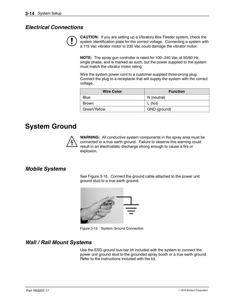
Mobile Systems See Figure 3-15. Connect the ground cable attached to the power unitground stud to a true earth ground.
Figure 3-15 System Ground Connection
Wall / Rail Mount Systems Use the ESD ground bus bar kit included with the system to connect thepower unit ground stud to the grounded spray booth or a true earth ground.Refer to the instructions included with the kit.
Operation 4-1
Part 1603227-17� 2018 Nordson Corporation
Section 4Operation
WARNING: Allow only qualified personnel to perform the following tasks.Follow the safety instructions in this document and all other relateddocumentation.
WARNING: This equipment can be dangerous unless it is used accordancewith the rules laid down in this manual.
WARNING: All electrically conductive equipment in the spray area must begrounded. Ungrounded or poorly grounded equipment can store anelectrostatic charge which can give personnel a severe shock or arc andcause a fire or explosion.
European Union, ATEX, Special Conditions for Safe Use1. The Encore XT manual applicator shall only be used with the associated
Encore XT/HD interface control unit and Encore XT controller powerunit, over the ambient temperature range of +15 �C to +40 �C.
2. Equipment may only be used in areas of low impact risk.
3. Caution should be taken when cleaning plastic surfaces of the EncoreXT controller and interface. There is a potential for static electricity buildup on these components.
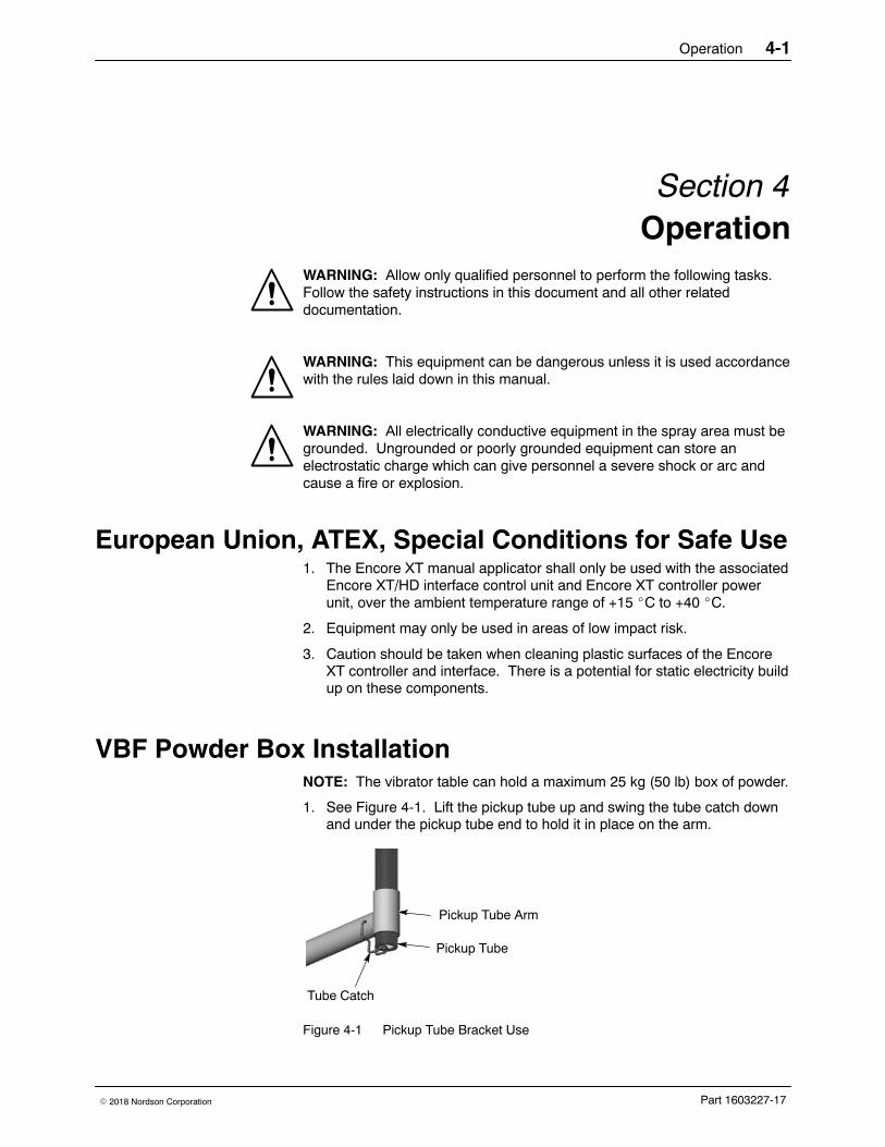
VBF Powder Box Installation NOTE: The vibrator table can hold a maximum 25 kg (50 lb) box of powder.
1. See Figure 4-1. Lift the pickup tube up and swing the tube catch downand under the pickup tube end to hold it in place on the arm.
Tube Catch
Pickup Tube
Pickup Tube Arm
Figure 4-1 Pickup Tube Bracket Use
Operation4-2
Part 1603227-17 � 2018 Nordson Corporation
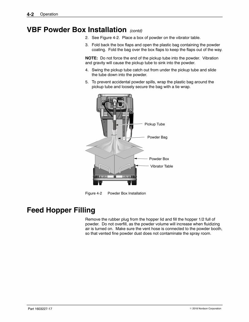
VBF Powder Box Installation (contd)
2. See Figure 4-2. Place a box of powder on the vibrator table.
3. Fold back the box flaps and open the plastic bag containing the powdercoating. Fold the bag over the box flaps to keep the flaps out of the way.
NOTE: Do not force the end of the pickup tube into the powder. Vibrationand gravity will cause the pickup tube to sink into the powder.
4. Swing the pickup tube catch out from under the pickup tube and slidethe tube down into the powder.
5. To prevent accidental powder spills, wrap the plastic bag around thepickup tube and loosely secure the bag with a tie wrap.
Pickup Tube
Powder Bag
Vibrator Table
Powder Box
Figure 4-2 Powder Box Installation
Feed Hopper Filling Remove the rubber plug from the hopper lid and fill the hopper 1/2 full ofpowder. Do not overfill, as the powder volume will increase when fluidizingair is turned on. Make sure the vent hose is connected to the powder booth,so that vented fine powder dust does not contaminate the spray room.
Operation 4-3
Part 1603227-17� 2018 Nordson Corporation
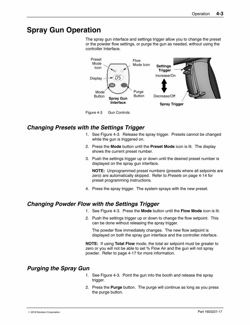
Spray Gun Operation The spray gun interface and settings trigger allow you to change the presetor the powder flow settings, or purge the gun as needed, without using thecontroller Interface.
ModeButton
PresetMode
Icon
FlowMode Icon
PurgeButton
DisplayIncrease/On
Decrease/OffSpray GunInterface
SettingsTrigger
Spray Trigger
Figure 4-3 Gun Controls
Changing Presets with the Settings Trigger 1. See Figure 4-3. Release the spray trigger. Presets cannot be changed
while the gun is triggered on.
2. Press the Mode button until the Preset Mode icon is lit. The displayshows the current preset number.
3. Push the settings trigger up or down until the desired preset number isdisplayed on the spray gun interface.
NOTE: Unprogrammed preset numbers (presets where all setpoints arezero) are automatically skipped. Refer to Presets on page 4-14 forpreset programming instructions.
4. Press the spray trigger. The system sprays with the new preset.
Changing Powder Flow with the Settings Trigger 1. See Figure 4-3. Press the Mode button until the Flow Mode icon is lit.
2. Push the settings trigger up or down to change the flow setpoint. Thiscan be done without releasing the spray trigger.
The powder flow immediately changes. The new flow setpoint isdisplayed on both the spray gun interface and the controller interface.
NOTE: If using Total Flow mode, the total air setpoint must be greater tozero or you will not be able to set % Flow Air and the gun will not spraypowder. Refer to page 4-17 for more information.
Purging the Spray Gun 1. See Figure 4-3. Point the gun into the booth and release the spray
trigger.
2. Press the Purge button. The purge will continue as long as you pressthe purge button.
Operation4-4
Part 1603227-17 � 2018 Nordson Corporation
Purging the Spray Gun (contd)
NOTE: If the settings trigger is configured for Purge, then pressing up ordown on the settings trigger purges the gun. Refer to ControllerConfiguration on page 4-21 for settings trigger configuration.
Purge the gun periodically to keep the powder path inside the spray gunclean. The purge length and frequency required will depend on theapplication.
NOTE: The purge air only cleans the spray gun powder path. To purge thepowder hose, disconnect it from the pump and the gun, place the gun endinside the booth, and blow it out from the pump end with compressed air.
Fluidizing Air Operation
Powder Feed Hopper If the controller is configured for a powder feed hopper, then turning on theinterface power turns on fluidizing air to the hopper. Adjust the fluidizing airpressure to 0.3−0.7 bar (5−15 psi). The pressure should be just enough sothe powder in the hopper “boils” gently. The fluidizing air causes the powderto increase in volume.
Fluidize the powder for 5−10 minutes to make sure it is evenly fluidized andno clumps are left before spraying.
Vibratory Box Feeder If the controller is configured for a vibratory box feeder, then the fluidizing airis turned on and off when the spray gun is triggered on and off.
Adjust the fluidizing air pressure to 0.3−0.7 bar (5−10 psi). The pressureshould just fluidize the powder around the pickup tube. The powder shouldnot boil violently or fountain out of the box.
When the spray gun is triggered off, the vibrator motor remains on for aconfigurable delay. This delay prevents rapid on/off motor cycling everytime you trigger the gun off and on and prolongs the life of the motor. Thedefault delay time is 30 seconds.
The vibrator motor can also be set to continuous operation. If set this way,press and release the spray gun trigger to start the motor. To turn off themotor, set the interface to Standby or turn off controller power.
To configure the system for a vibratory box feeder, change the VBF delaytime, or set the vibrator motor to continuous operation, refer to ControllerConfiguration on page 4-21.
Operation 4-5
Part 1603227-17� 2018 Nordson Corporation
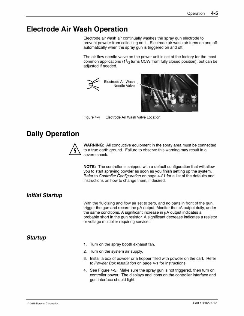
Electrode Air Wash Operation Electrode air wash air continually washes the spray gun electrode toprevent powder from collecting on it. Electrode air wash air turns on and offautomatically when the spray gun is triggered on and off.
The air flow needle valve on the power unit is set at the factory for the mostcommon applications (11/2 turns CCW from fully closed position), but can beadjusted if needed.
Electrode Air WashNeedle Valve
Figure 4-4 Electrode Air Wash Valve Location
Daily Operation WARNING: All conductive equipment in the spray area must be connectedto a true earth ground. Failure to observe this warning may result in asevere shock.
NOTE: The controller is shipped with a default configuration that will allowyou to start spraying powder as soon as you finish setting up the system.Refer to Controller Configuration on page 4-21 for a list of the defaults andinstructions on how to change them, if desired.
Initial Startup With the fluidizing and flow air set to zero, and no parts in front of the gun,trigger the gun and record the μA output. Monitor the μA output daily, underthe same conditions. A significant increase in μA output indicates aprobable short in the gun resistor. A significant decrease indicates a resistoror voltage multiplier requiring service.
Startup 1. Turn on the spray booth exhaust fan.
2. Turn on the system air supply.
3. Install a box of powder or a hopper filled with powder on the cart. Referto Powder Box Installation on page 4-1 for instructions.
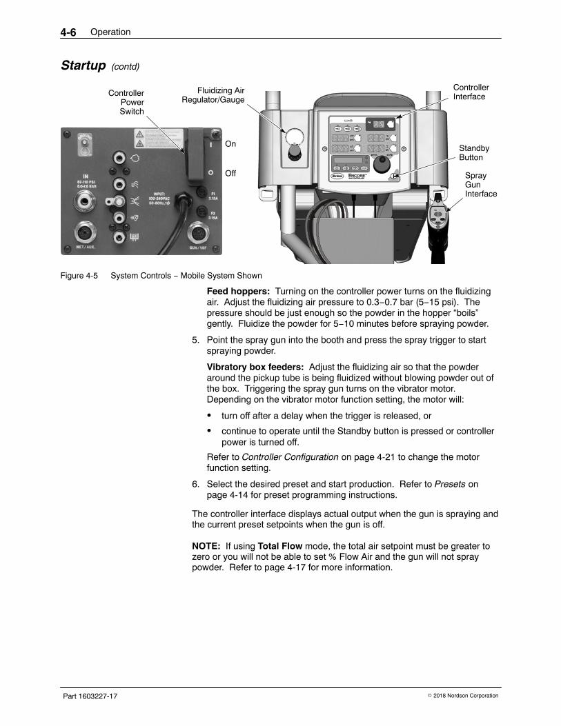
4. See Figure 4-5. Make sure the spray gun is not triggered, then turn oncontroller power. The displays and icons on the controller interface andgun interface should light.
Operation4-6
Part 1603227-17 � 2018 Nordson Corporation
Startup (contd)
Fluidizing AirRegulator/Gauge
SprayGunInterface
ControllerInterfaceController
PowerSwitch
On
Off
StandbyButton
Figure 4-5 System Controls − Mobile System Shown
Feed hoppers: Turning on the controller power turns on the fluidizingair. Adjust the fluidizing air pressure to 0.3−0.7 bar (5−15 psi). Thepressure should be just enough so the powder in the hopper “boils”gently. Fluidize the powder for 5−10 minutes before spraying powder.
5. Point the spray gun into the booth and press the spray trigger to startspraying powder.
Vibratory box feeders: Adjust the fluidizing air so that the powderaround the pickup tube is being fluidized without blowing powder out ofthe box. Triggering the spray gun turns on the vibrator motor.Depending on the vibrator motor function setting, the motor will:
� turn off after a delay when the trigger is released, or
� continue to operate until the Standby button is pressed or controllerpower is turned off.
Refer to Controller Configuration on page 4-21 to change the motorfunction setting.
6. Select the desired preset and start production. Refer to Presets onpage 4-14 for preset programming instructions.
The controller interface displays actual output when the gun is spraying andthe current preset setpoints when the gun is off.
NOTE: If using Total Flow mode, the total air setpoint must be greater tozero or you will not be able to set % Flow Air and the gun will not spraypowder. Refer to page 4-17 for more information.
Operation 4-7
Part 1603227-17� 2018 Nordson Corporation
Standby Button Use the Standby button shown in Figure 4-5 to shut off the interface anddisable the spray gun during breaks in production. When the controllerinterface is off the spray gun cannot be triggered, and the spray guninterface is disabled.
To shut off controller power, use the power switch on the power unit.
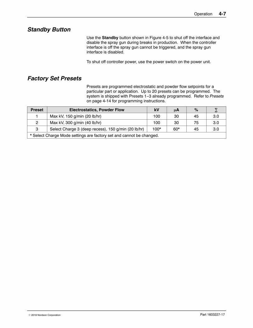
Factory Set Presets Presets are programmed electrostatic and powder flow setpoints for aparticular part or application. Up to 20 presets can be programmed. Thesystem is shipped with Presets 1−3 already programmed. Refer to Presetson page 4-14 for programming instructions.
Preset Electrostatics, Powder Flow kV �A % �
1 Max kV, 150 g/min (20 lb/hr) 100 30 45 3.0
2 Max kV, 300 g/min (40 lb/hr) 100 30 75 3.0
3 Select Charge 3 (deep recess), 150 g/min (20 lb/hr) 100* 60* 45 3.0
* Select Charge Mode settings are factory set and cannot be changed.
Operation4-8
Part 1603227-17 � 2018 Nordson Corporation
Changing Flat Spray Nozzles
WARNING: Release the spray gun trigger, put the controller to sleep, andground the electrode before performing this procedure. Failure to observethis warning could result in a severe electrical shock.
NOTE: The tapered electrode holder of the electrode assembly has beendesigned for optimized cleaning during color changes on systems using flatspray nozzles. This tapered electrode holder will not accept conicaldeflectors.
1. Purge the spray gun and press the Enable/Disable button to put thecontroller to sleep in order to prevent accidental gun triggering.
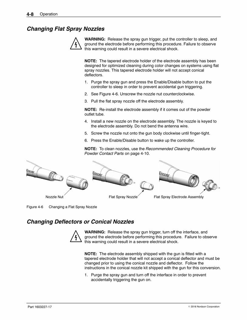
2. See Figure 4-6. Unscrew the nozzle nut counterclockwise.
3. Pull the flat spray nozzle off the electrode assembly.
NOTE: Re-install the electrode assembly if it comes out of the powderoutlet tube.
4. Install a new nozzle on the electrode assembly. The nozzle is keyed tothe electrode assembly. Do not bend the antenna wire.
5. Screw the nozzle nut onto the gun body clockwise until finger-tight.
6. Press the Enable/Disable button to wake up the controller.
NOTE: To clean nozzles, use the Recommended Cleaning Procedure forPowder Contact Parts on page 4-10.
Nozzle Nut Flat Spray Nozzle Flat Spray Electrode Assembly
Figure 4-6 Changing a Flat Spray Nozzle
Changing Deflectors or Conical Nozzles
WARNING: Release the spray gun trigger, turn off the interface, andground the electrode before performing this procedure. Failure to observethis warning could result in a severe electrical shock.
NOTE: The electrode assembly shipped with the gun is fitted with atapered electrode holder that will not accept a conical deflector and must bechanged prior to using the conical nozzle and deflector. Follow theinstructions in the conical nozzle kit shipped with the gun for this conversion.
1. Purge the spray gun and turn off the interface in order to preventaccidentally triggering the gun on.
Operation 4-9
Part 1603227-17� 2018 Nordson Corporation
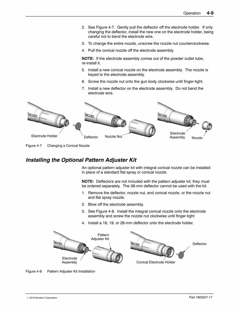
2. See Figure 4-7. Gently pull the deflector off the electrode holder. If onlychanging the deflector, install the new one on the electrode holder, beingcareful not to bend the electrode wire.
3. To change the entire nozzle, unscrew the nozzle nut counterclockwise.
4. Pull the conical nozzle off the electrode assembly.
NOTE: If the electrode assembly comes out of the powder outlet tube,re-install it.
5. Install a new conical nozzle on the electrode assembly. The nozzle iskeyed to the electrode assembly.
6. Screw the nozzle nut onto the gun body clockwise until finger-tight.
7. Install a new deflector on the electrode assembly. Do not bend theelectrode wire.
Deflector Nozzle Nut NozzleElectrode HolderElectrodeAssembly
Figure 4-7 Changing a Conical Nozzle
Installing the Optional Pattern Adjuster Kit An optional pattern adjuster kit with integral conical nozzle can be installedin place of a standard flat spray or conical nozzle.
NOTE: Deflectors are not included with the pattern adjuster kit; they mustbe ordered separately. The 38-mm deflector cannot be used with the kit.
1. Remove the deflector, nozzle nut, and conical nozzle, or the nozzle nutand flat spray nozzle.
2. Blow off the electrode assembly.
3. See Figure 4-8. Install the integral conical nozzle onto the electrodeassembly and screw the nozzle nut clockwise until finger-tight
4. Install a 16, 19, or 26-mm deflector onto the electrode holder.
Deflector
ElectrodeAssembly
PatternAdjuster Kit
Conical Electrode Holder
Figure 4-8 Pattern Adjuster Kit Installation
Operation4-10
Part 1603227-17 � 2018 Nordson Corporation
Shutdown1. Purge the spray gun by pressing the Purge button until no more powder
is blown from the gun.
2. Press the standby button to turn off the spray gun and interface.
3. Turn off the system air supply and relieve the system air pressure.
4. If shutting down for the night or a longer period of time, move the powerunit switch to the OFF position to shut off system power.
5. Perform the Daily Maintenance procedures on page 4-11.
Maintenance
WARNING: Allow only qualified personnel to perform the following tasks.Follow the safety instructions in this document and all other relateddocumentation.
WARNING: Before performing the following tasks, turn off the controllerand disconnect system power. Relieve system air pressure and disconnectthe system from its input air supply. Failure to observe this warning mayresult in personal injury.
Recommended Cleaning Procedure for Powder Contact Parts Nordson Corporation recommends using an ultrasonic cleaning machineand Oakite� BetaSolv emulsion cleaner to clean spray gun nozzles andpowder path parts.
NOTE: Do not immerse the electrode assembly in solvent. It cannot bedisassembled; cleaning solution and rinse water will remain inside theassembly.
1. Fill an ultrasonic cleaner with BetaSolv or an equivalent emulsioncleaning solution at room temperature. Do not heat the cleaningsolution.
2. Remove the parts to be cleaned from the gun. Remove the O-rings.Blow off the parts with low-pressure compressed air.
NOTE: Do not allow the O-rings to come in contact with the cleaningsolution.
3. Place the parts in the ultrasonic cleaner and run the cleaner until allparts are clean and free of impact fusion.
4. Rinse all parts in clean water and dry before re-assembling the spraygun. Inspect the O-rings and replace any that are damaged.
NOTE: Do not use sharp or hard tools that will scratch or gouge the smoothsurfaces of powder contact parts. Scratches will cause impact fusion.
Operation 4-11
Part 1603227-17� 2018 Nordson Corporation
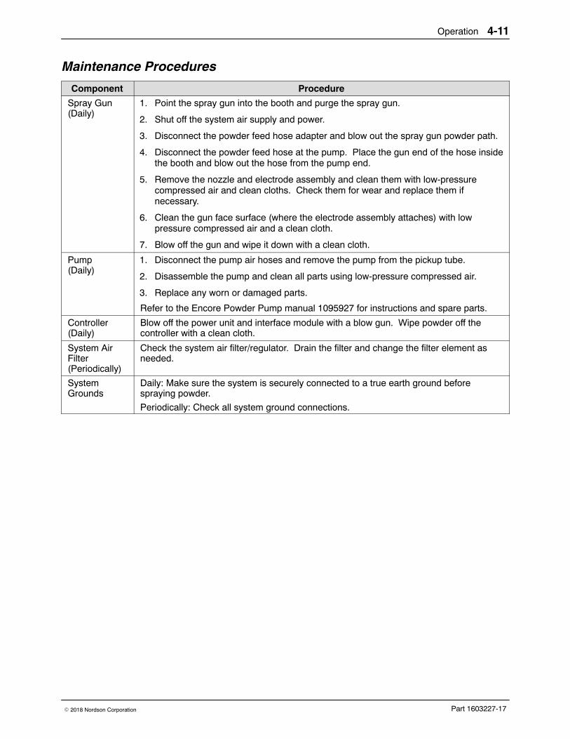
Maintenance Procedures
Component Procedure
Spray Gun(Daily)
1. Point the spray gun into the booth and purge the spray gun.
2. Shut off the system air supply and power.
3. Disconnect the powder feed hose adapter and blow out the spray gun powder path.
4. Disconnect the powder feed hose at the pump. Place the gun end of the hose insidethe booth and blow out the hose from the pump end.
5. Remove the nozzle and electrode assembly and clean them with low-pressurecompressed air and clean cloths. Check them for wear and replace them ifnecessary.
6. Clean the gun face surface (where the electrode assembly attaches) with lowpressure compressed air and a clean cloth.
7. Blow off the gun and wipe it down with a clean cloth.
Pump(Daily)
1. Disconnect the pump air hoses and remove the pump from the pickup tube.
2. Disassemble the pump and clean all parts using low-pressure compressed air.
3. Replace any worn or damaged parts.
Refer to the Encore Powder Pump manual 1095927 for instructions and spare parts.
Controller(Daily)
Blow off the power unit and interface module with a blow gun. Wipe powder off thecontroller with a clean cloth.
System AirFilter(Periodically)
Check the system air filter/regulator. Drain the filter and change the filter element asneeded.
SystemGrounds
Daily: Make sure the system is securely connected to a true earth ground beforespraying powder.
Periodically: Check all system ground connections.
Operation4-12
Part 1603227-17 � 2018 Nordson Corporation
Using the Controller Interface
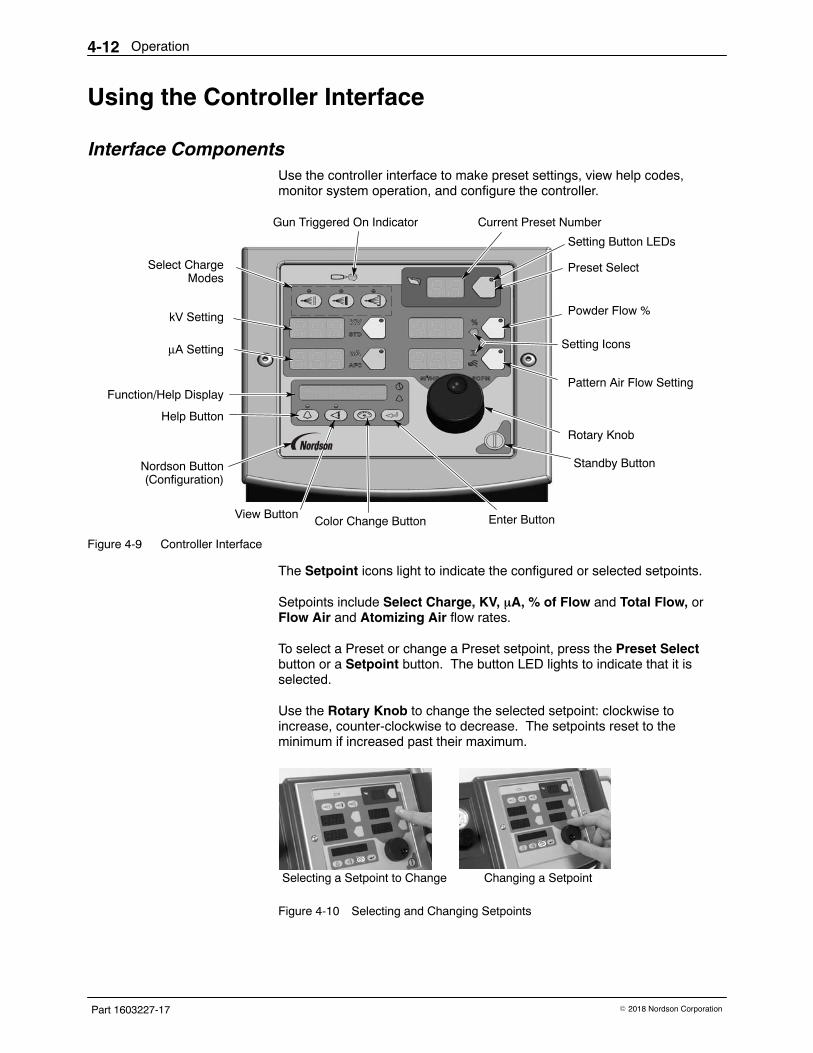
Interface Components Use the controller interface to make preset settings, view help codes,monitor system operation, and configure the controller.
Gun Triggered On Indicator
Select ChargeModes
kV Setting
Function/Help Display
Current Preset Number
Powder Flow %
Rotary Knob
Standby ButtonNordson Button(Configuration)
Setting Button LEDs
Preset Select
Setting Icons
Pattern Air Flow Setting
μA Setting
Help Button
View Button Enter ButtonColor Change Button
Figure 4-9 Controller Interface
The Setpoint icons light to indicate the configured or selected setpoints.
Setpoints include Select Charge, KV, �A, % of Flow and Total Flow, orFlow Air and Atomizing Air flow rates.
To select a Preset or change a Preset setpoint, press the Preset Selectbutton or a Setpoint button. The button LED lights to indicate that it isselected.
Use the Rotary Knob to change the selected setpoint: clockwise toincrease, counter-clockwise to decrease. The setpoints reset to theminimum if increased past their maximum.
Selecting a Setpoint to Change Changing a Setpoint
Figure 4-10 Selecting and Changing Setpoints
Operation 4-13
Part 1603227-17� 2018 Nordson Corporation
Help Codes
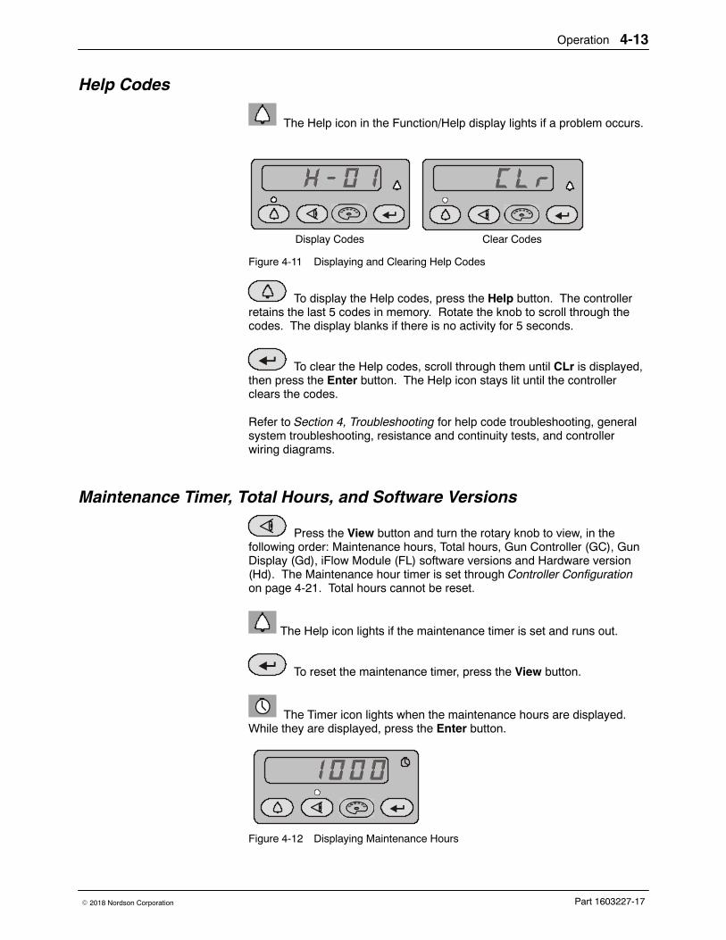
The Help icon in the Function/Help display lights if a problem occurs.
Display Codes Clear Codes
Figure 4-11 Displaying and Clearing Help Codes
To display the Help codes, press the Help button. The controllerretains the last 5 codes in memory. Rotate the knob to scroll through thecodes. The display blanks if there is no activity for 5 seconds.
To clear the Help codes, scroll through them until CLr is displayed,then press the Enter button. The Help icon stays lit until the controllerclears the codes.
Refer to Section 4, Troubleshooting for help code troubleshooting, generalsystem troubleshooting, resistance and continuity tests, and controllerwiring diagrams.
Maintenance Timer, Total Hours, and Software Versions
Press the View button and turn the rotary knob to view, in thefollowing order: Maintenance hours, Total hours, Gun Controller (GC), GunDisplay (Gd), iFlow Module (FL) software versions and Hardware version(Hd). The Maintenance hour timer is set through Controller Configurationon page 4-21. Total hours cannot be reset.
The Help icon lights if the maintenance timer is set and runs out.
To reset the maintenance timer, press the View button.
The Timer icon lights when the maintenance hours are displayed.While they are displayed, press the Enter button.
Figure 4-12 Displaying Maintenance Hours
Operation4-14
Part 1603227-17 � 2018 Nordson Corporation
Presets Presets are programmed electrostatic and powder flow setpoints that allowthe operator to quickly change spray settings simply by changing the presetnumber.
The controller can store 20 presets. Presets 1, 2, and 3 are programmed atthe factory for the most common applications. Refer to page 4-7 for theirsetpoints. These setpoints can be adjusted as needed. Presets 4−17 canbe programmed as needed.
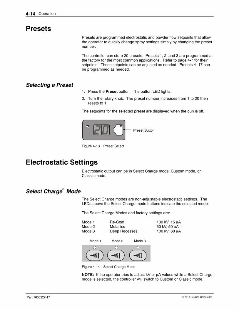
Selecting a Preset 1. Press the Preset button. The button LED lights.
2. Turn the rotary knob. The preset number increases from 1 to 20 thenresets to 1.
The setpoints for the selected preset are displayed when the gun is off.
Preset Button
Figure 4-13 Preset Select
Electrostatic Settings Electrostatic output can be in Select Charge mode, Custom mode, orClassic mode.
Select Charge� Mode The Select Charge modes are non-adjustable electrostatic settings. TheLEDs above the Select Charge mode buttons indicate the selected mode.
The Select Charge Modes and factory settings are:
Mode 1 Re-Coat 100 kV, 15 μAMode 2 Metallics 50 kV, 50 μAMode 3 Deep Recesses 100 kV, 60 μA
Mode 1 Mode 2 Mode 3
Figure 4-14 Select Charge Mode
NOTE: If the operator tries to adjust kV or μA values while a Select Chargemode is selected, the controller will switch to Custom or Classic mode.
Operation 4-15
Part 1603227-17� 2018 Nordson Corporation
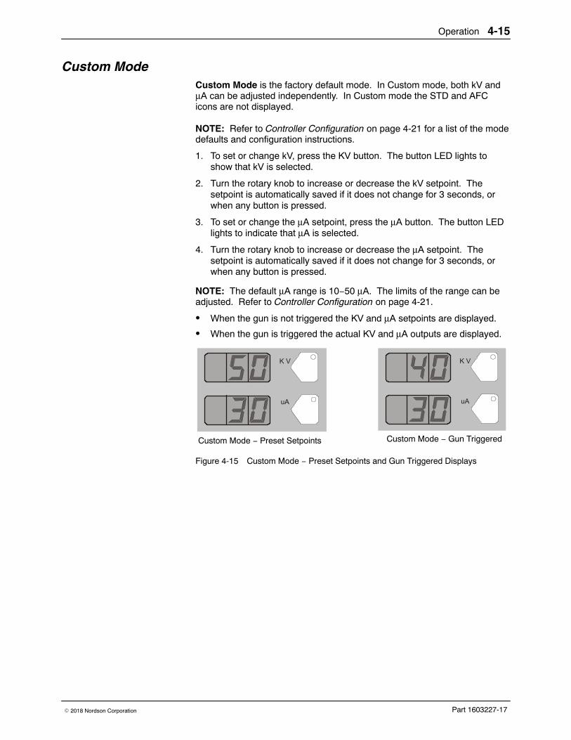
Custom Mode Custom Mode is the factory default mode. In Custom mode, both kV andμA can be adjusted independently. In Custom mode the STD and AFCicons are not displayed.
NOTE: Refer to Controller Configuration on page 4-21 for a list of the modedefaults and configuration instructions.
1. To set or change kV, press the KV button. The button LED lights toshow that kV is selected.
2. Turn the rotary knob to increase or decrease the kV setpoint. Thesetpoint is automatically saved if it does not change for 3 seconds, orwhen any button is pressed.
3. To set or change the μA setpoint, press the μA button. The button LEDlights to indicate that μA is selected.
4. Turn the rotary knob to increase or decrease the μA setpoint. Thesetpoint is automatically saved if it does not change for 3 seconds, orwhen any button is pressed.
NOTE: The default μA range is 10−50 μA. The limits of the range can beadjusted. Refer to Controller Configuration on page 4-21.
� When the gun is not triggered the KV and μA setpoints are displayed.
� When the gun is triggered the actual KV and μA outputs are displayed.
Custom Mode − Preset Setpoints Custom Mode − Gun Triggered
Figure 4-15 Custom Mode − Preset Setpoints and Gun Triggered Displays
Operation4-16
Part 1603227-17 � 2018 Nordson Corporation
Classic Mode To use Classic mode, the controller must be configured for it. Refer toController Configuration on page 4-21.
In Classic mode you can choose to control kV (STD) output or μA (AFC)output, but not both at the same time.
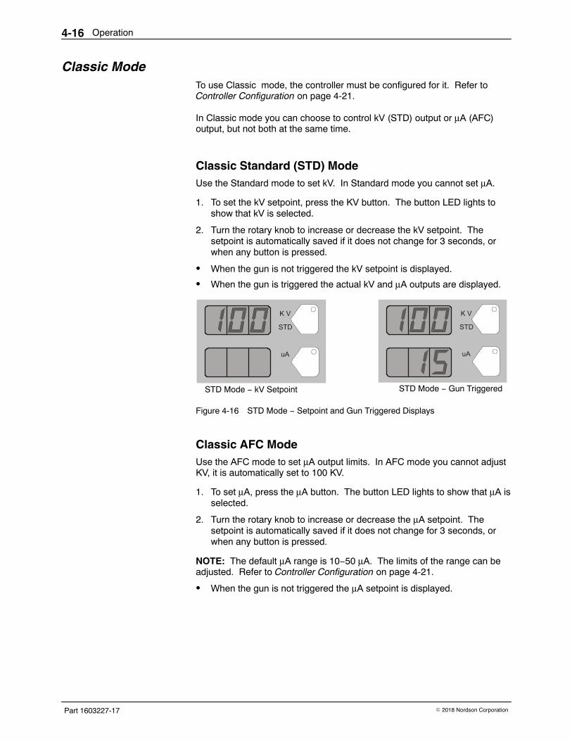
Classic Standard (STD) ModeUse the Standard mode to set kV. In Standard mode you cannot set μA.
1. To set the kV setpoint, press the KV button. The button LED lights toshow that kV is selected.
2. Turn the rotary knob to increase or decrease the kV setpoint. Thesetpoint is automatically saved if it does not change for 3 seconds, orwhen any button is pressed.
� When the gun is not triggered the kV setpoint is displayed.
� When the gun is triggered the actual kV and μA outputs are displayed.
STD Mode − kV Setpoint STD Mode − Gun Triggered
Figure 4-16 STD Mode − Setpoint and Gun Triggered Displays
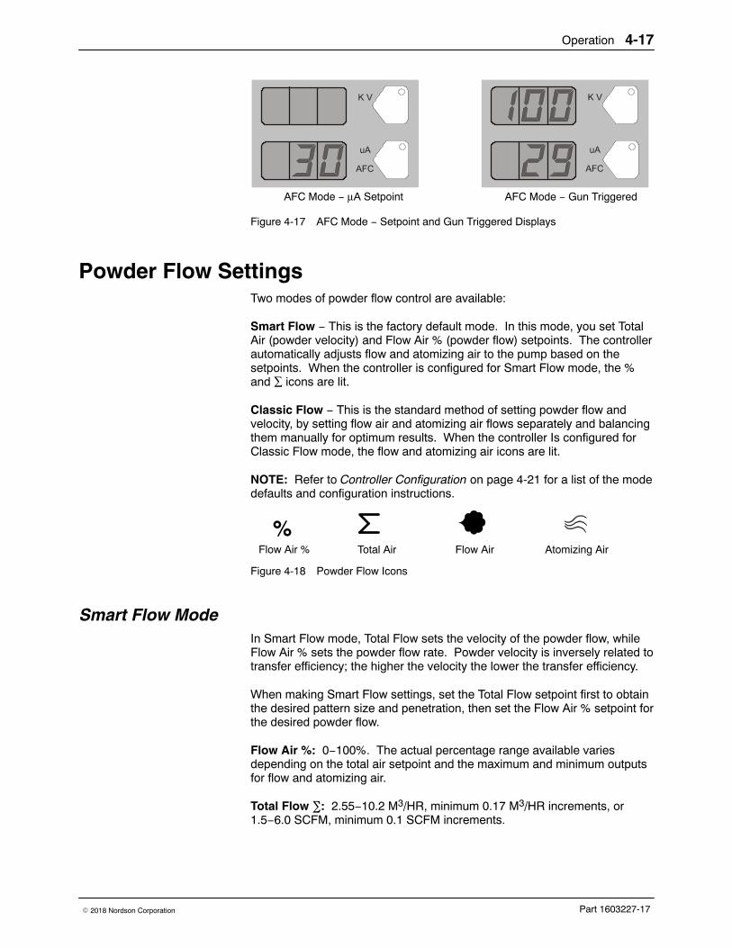
Classic AFC Mode Use the AFC mode to set μA output limits. In AFC mode you cannot adjustKV, it is automatically set to 100 KV.
1. To set μA, press the μA button. The button LED lights to show that μA isselected.
2. Turn the rotary knob to increase or decrease the μA setpoint. Thesetpoint is automatically saved if it does not change for 3 seconds, orwhen any button is pressed.
NOTE: The default μA range is 10−50 μA. The limits of the range can beadjusted. Refer to Controller Configuration on page 4-21.
� When the gun is not triggered the μA setpoint is displayed.
Operation 4-17
Part 1603227-17� 2018 Nordson Corporation
AFC Mode − Gun TriggeredAFC Mode − μA Setpoint
Figure 4-17 AFC Mode − Setpoint and Gun Triggered Displays
Powder Flow Settings Two modes of powder flow control are available:
Smart Flow − This is the factory default mode. In this mode, you set TotalAir (powder velocity) and Flow Air % (powder flow) setpoints. The controllerautomatically adjusts flow and atomizing air to the pump based on thesetpoints. When the controller is configured for Smart Flow mode, the %and ∑ icons are lit.
Classic Flow − This is the standard method of setting powder flow andvelocity, by setting flow air and atomizing air flows separately and balancingthem manually for optimum results. When the controller Is configured forClassic Flow mode, the flow and atomizing air icons are lit.
NOTE: Refer to Controller Configuration on page 4-21 for a list of the modedefaults and configuration instructions.
Flow Air Atomizing AirFlow Air % Total Air
%
Figure 4-18 Powder Flow Icons
Smart Flow Mode In Smart Flow mode, Total Flow sets the velocity of the powder flow, whileFlow Air % sets the powder flow rate. Powder velocity is inversely related totransfer efficiency; the higher the velocity the lower the transfer efficiency.
When making Smart Flow settings, set the Total Flow setpoint first to obtainthe desired pattern size and penetration, then set the Flow Air % setpoint forthe desired powder flow.
Flow Air %: 0−100%. The actual percentage range available variesdepending on the total air setpoint and the maximum and minimum outputsfor flow and atomizing air.
Total Flow �: 2.55−10.2 M3/HR, minimum 0.17 M3/HR increments, or1.5−6.0 SCFM, minimum 0.1 SCFM increments.
Operation4-18
Part 1603227-17 � 2018 Nordson Corporation
Smart Flow Mode (contd)
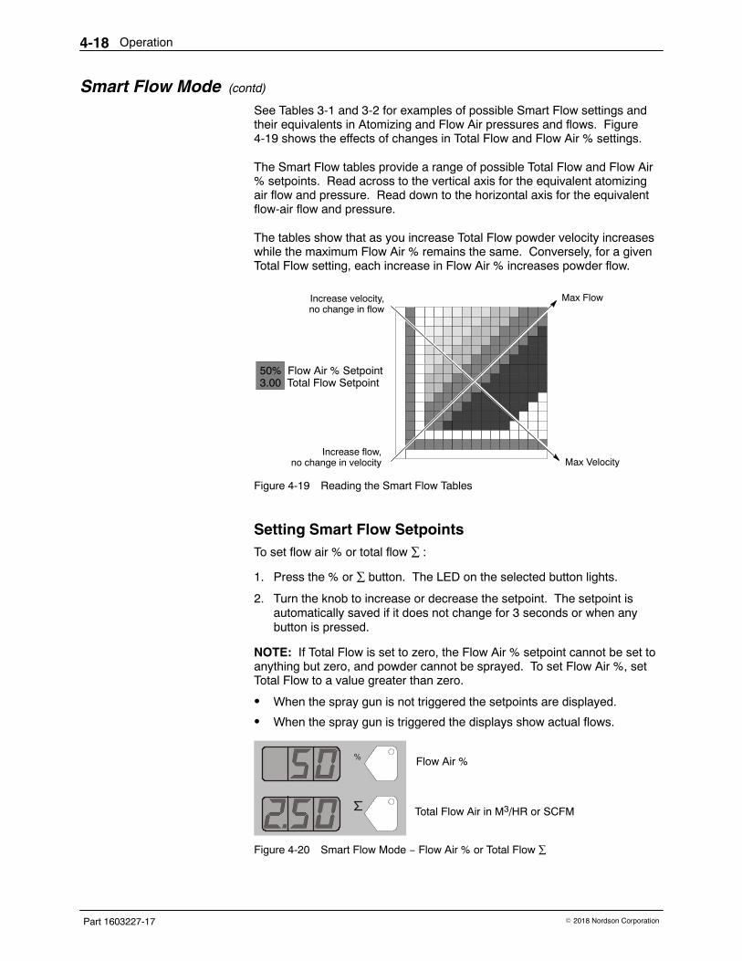
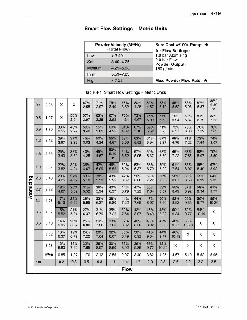
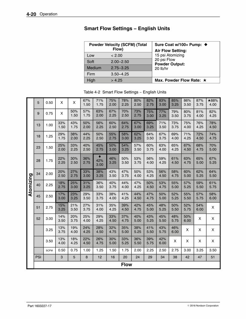
See Tables 3-1 and 3-2 for examples of possible Smart Flow settings andtheir equivalents in Atomizing and Flow Air pressures and flows. Figure4-19 shows the effects of changes in Total Flow and Flow Air % settings.
The Smart Flow tables provide a range of possible Total Flow and Flow Air% setpoints. Read across to the vertical axis for the equivalent atomizingair flow and pressure. Read down to the horizontal axis for the equivalentflow-air flow and pressure.
The tables show that as you increase Total Flow powder velocity increaseswhile the maximum Flow Air % remains the same. Conversely, for a givenTotal Flow setting, each increase in Flow Air % increases powder flow.
Increase flow,no change in velocity
Max FlowIncrease velocity,no change in flow
50% Flow Air % Setpoint3.00 Total Flow Setpoint
Max Velocity
Figure 4-19 Reading the Smart Flow Tables
Setting Smart Flow Setpoints To set flow air % or total flow ∑ :
1. Press the % or ∑ button. The LED on the selected button lights.
2. Turn the knob to increase or decrease the setpoint. The setpoint isautomatically saved if it does not change for 3 seconds or when anybutton is pressed.
NOTE: If Total Flow is set to zero, the Flow Air % setpoint cannot be set toanything but zero, and powder cannot be sprayed. To set Flow Air %, setTotal Flow to a value greater than zero.
� When the spray gun is not triggered the setpoints are displayed.
� When the spray gun is triggered the displays show actual flows.
Flow Air %
Total Flow Air in M3/HR or SCFM
Figure 4-20 Smart Flow Mode − Flow Air % or Total Flow ∑
Operation 4-19
Part 1603227-17� 2018 Nordson Corporation
Smart Flow Settings − Metric Units
Powder Velocity (M3/Hr) (Total Flow)
Sure Coat w/100+ Pump: �
Air Flow Settings: 1.0 bar Atomizing2.0 bar FlowPowder Output:150 g/min.
Low < 3.40
Soft 3.40−4.25
Medium 4.25−5.53
Firm 5.53−7.23
High > 7.23 Max. Powder Flow Rate: �
Table 4-1 Smart Flow Settings − Metric Units
Ato
miz
ing
0.4 0.85 X X67%2.55
71%2.97
75%3.40
78%3.82
80%4.25
82%4.67
83%5.10
85%5.52
86%5.95
87%6.37
88%6.80�
0.6 1.27 X50%2.54
57%2.97
63%3.39
67%3.82
70%4.24
73%4.67
75%5.09
77%5.52
79%5.94
80%6.37
81%6.79
82%7.22
0.9 1.7033%2.55
43%2.97
50%3.40
55%3.82
60%4.25
64%4.67
67%5.10
69%5.52
71%5.95
73%6.37
75%6.80
76%7.22
78%7.65
1.2 2.1229%2.97
37%3.39
45%3.82
50%4.24
55%4.67
58%5.09
62%5.52
64%5.94
67%6.37
69%6.79
71%7.22
72%7.64
74%8.07
1.6 2.5525%3.40
33%3.82
40%4.25
45%4.67
50%5.10�
54%5.52
57%5.95
60%6.37
63%6.80
65%7.22
67%7.65
68%8.07
70%8.50
1.9 2.9722%3.82
30%4.24
36%4.67
42%5.09
46%5.52
50%5.94
53%6.37
56%6.79
59%7.22
61%7.64
63%8.07
65%8.49
67%8.92
2.3 3.4020%4.25
27%4.67
33%5.10
38%5.52
43%5.95
47%6.37
50%6.80
53%7.22
56%7.65
58%8.07
60%8.50
62%8.92
64%9.35
2.7 3.8218%4.67
25%5.09
31%5.52
36%5.94
40%6.37
44%6.79
47%7.22
50%7.64
53%8.07
55%8.49
57%8.92
59%9.34
61%9.77
3.1 4.2517%5.10
23%5.52
29%5.95
33%6.37
38%6.80
41%7.22
44%7.65
47%8.07
50%8.50
52%8.92
55%9.35
56%9.77
58%10.20
3.5 4.6715%5.52
21%5.94
27%6.37
31%6.79
35%7.22
39%7.64
42%8.07
45%8.49
48%8.92
50%9.34
52%9.77
54%10.19 X
3.6 5.1014%5.95
20%6.37
25%6.80
29%7.22
33%7.65
37%8.07
40%8.50
43%8.92
45%9.35
48%9.77
50%10.20 X X
5.5213%6.37
19%6.79
24%7.22
28%7.64
32%8.07
35%8.49
38%8.92
41%9.34
44%9.77
46%10.19 X X X
5.9513%6.80
18%7.22
22%7.65
26%8.07
30%8.50
33%8.92
36%9.35
39%9.77
42%10.20 X X X X
M3/Hr 0.85 1.27 1.70 2.12 2.55 2.97 3.40 3.82 4.25 4.67 5.10 5.52 5.95
BAR 0.2 0.3 0.5 0.8 1.1 1.4 1.7 2.0 2.3 2.6 2.9 3.2 3.5
Flow
Operation4-20
Part 1603227-17 � 2018 Nordson Corporation
Smart Flow Settings − English Units
Powder Velocity (SCFM) (TotalFlow)
Sure Coat w/100+ Pump: �
Air Flow Setting:15 psi Atomizing20 psi FlowPowder Output:20 lb/hr
Low < 2.00
Soft 2.00−2.50
Medium 2.75−3.25
Firm 3.50−4.25
High > 4.25 Max. Powder Flow Rate: �
Table 4-2 Smart Flow Settings − English Units
Ato
miz
ing
5 0.50 X X67%1.50
71%1.75
75%2.00
78%2.25
80%2.50
82%2.75
83%3.00
85%3.25
86%3.50
87%3.75
�88%4.00
9 0.75 X50%1.50
57%1.75
63%2.00
67%2.25
70%2.50
73%2.75
75%3.00
77%3.25
79%3.50
80%3.75
81%4.00
82%4.25
13 1.0033%1.50
43%1.75
50%2.00
56%2.25
60%2.50
64%2.75
67%3.00
69%3.25
71%3.50
73%3.75
75%4.00
76%4.25
78%4.50
18 1.2529%1.75
38%2.00
44%2.25
50%2.50
55%2.75
58%3.00
62%3.25
64%3.50
67%3.75
69%4.00
71%4.25
72%4.50
74%4.75
23 1.5025%2.00
33%2.25
40%2.50
45%2.75
50%3.00
54%3.25
57%3.50
60%3.75
63%4.00
65%4.25
67%4.50
68%4.75
70%5.00
28 1.7522%2.25
30%2.50
36%2.75
�42%3.00
46%3.25
50%3.50
53%3.75
56%4.00
59%4.25
61%4.50
63%4.75
65%5.00
67%5.25
34 2.0020%2.50
27%2.75
33%3.00
38%3.25
43%3.50
47%3.75
50%4.00
53%4.25
56%4.50
58%4.75
60%5.00
62%5.25
64%5.50
40 2.2518%2.75
25%3.00
31%3.25
36%3.50
40%3.75
44%4.00
47%4.25
50%4.50
53%4.75
55%5.00
57%5.25
59%5.50
61%5.75
45 2.5017%3.00
23%3.25
29%3.50
33%3.75
38%4.00
41%4.25
44%4.50
47%4.75
50%5.00
52%5.25
55%5.50
57%5.75
58%6.00
51 2.7515%3.25
21%3.50
27%3.75
31%4.00
35%4.25
39%4.50
42%4.75
45%5.00
48%5.25
50%5.50
52%5.75
54%6.00 X
52 3.0014%3.50
20%3.75
25%4.00
29%4.25
33%4.50
37%4.75
40%5.00
43%5.25
45%5.50
48%5.75
50%6.00 X X
3.2513%3.75
19%4.00
24%4.25
28%4.50
32%4.75
35%5.00
38%5.25
41%5.50
43%5.75
46%6.00 X X X
3.5013%4.00
18%4.25
22%4.50
26%4.75
30%5.00
33%5.25
36%5.50
39%5.75
42%6.00 X X X X
SCFM 0.50 0.75 1.00 1.25 1.50 1.75 2.00 2.25 2.50 2.75 3.00 3.25 3.50
PSI 3 5 8 12 16 20 24 29 34 38 42 47 51
Flow
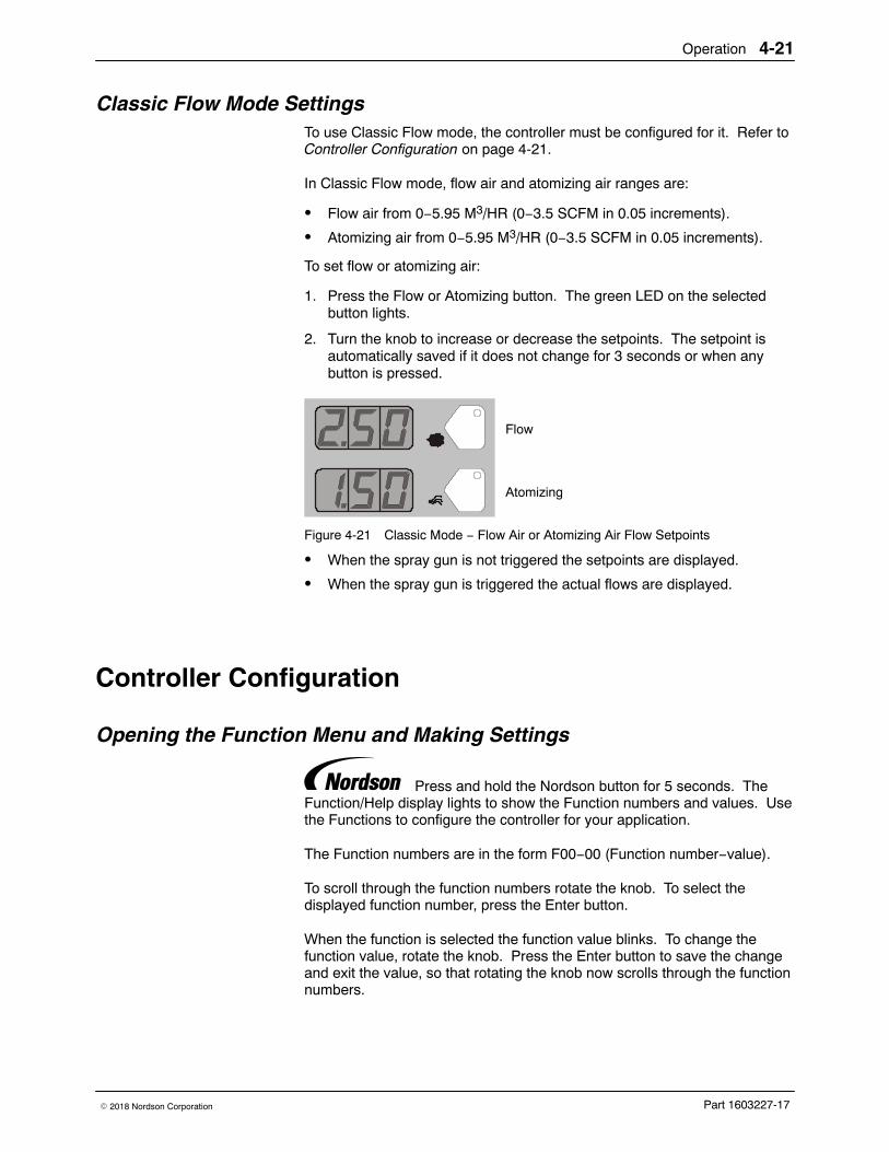
Operation 4-21
Part 1603227-17� 2018 Nordson Corporation
Classic Flow Mode Settings To use Classic Flow mode, the controller must be configured for it. Refer toController Configuration on page 4-21.
In Classic Flow mode, flow air and atomizing air ranges are:
� Flow air from 0−5.95 M3/HR (0−3.5 SCFM in 0.05 increments).
� Atomizing air from 0−5.95 M3/HR (0−3.5 SCFM in 0.05 increments).
To set flow or atomizing air:
1. Press the Flow or Atomizing button. The green LED on the selectedbutton lights.
2. Turn the knob to increase or decrease the setpoints. The setpoint isautomatically saved if it does not change for 3 seconds or when anybutton is pressed.
Flow
Atomizing
Figure 4-21 Classic Mode − Flow Air or Atomizing Air Flow Setpoints
� When the spray gun is not triggered the setpoints are displayed.
� When the spray gun is triggered the actual flows are displayed.
Controller Configuration
Opening the Function Menu and Making Settings
Press and hold the Nordson button for 5 seconds. TheFunction/Help display lights to show the Function numbers and values. Usethe Functions to configure the controller for your application.
The Function numbers are in the form F00−00 (Function number−value).
To scroll through the function numbers rotate the knob. To select thedisplayed function number, press the Enter button.
When the function is selected the function value blinks. To change thefunction value, rotate the knob. Press the Enter button to save the changeand exit the value, so that rotating the knob now scrolls through the functionnumbers.
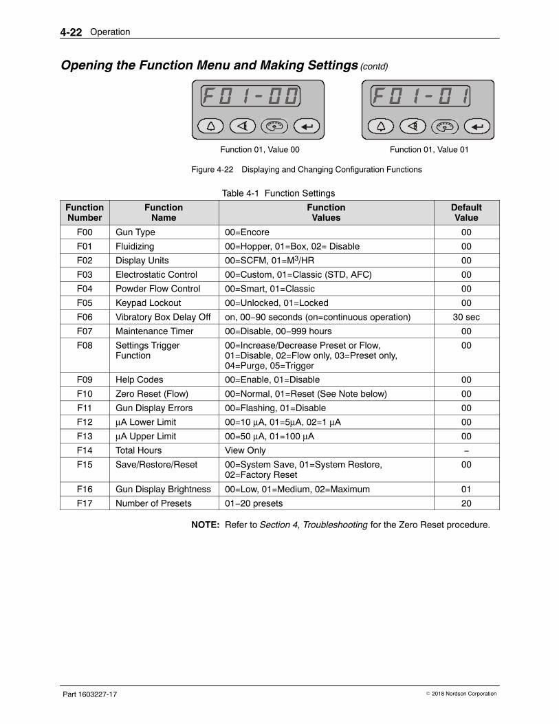
Operation4-22
Part 1603227-17 � 2018 Nordson Corporation
Opening the Function Menu and Making Settings (contd)
Function 01, Value 00 Function 01, Value 01
Figure 4-22 Displaying and Changing Configuration Functions
Table 4-1 Function Settings
FunctionNumber
FunctionName
FunctionValues
DefaultValue
F00 Gun Type 00=Encore 00
F01 Fluidizing 00=Hopper, 01=Box, 02= Disable 00
F02 Display Units 00=SCFM, 01=M3/HR 00
F03 Electrostatic Control 00=Custom, 01=Classic (STD, AFC) 00
F04 Powder Flow Control 00=Smart, 01=Classic 00
F05 Keypad Lockout 00=Unlocked, 01=Locked 00
F06 Vibratory Box Delay Off on, 00−90 seconds (on=continuous operation) 30 sec
F07 Maintenance Timer 00=Disable, 00−999 hours 00
F08 Settings TriggerFunction
00=Increase/Decrease Preset or Flow,01=Disable, 02=Flow only, 03=Preset only,04=Purge, 05=Trigger
00
F09 Help Codes 00=Enable, 01=Disable 00
F10 Zero Reset (Flow) 00=Normal, 01=Reset (See Note below) 00
F11 Gun Display Errors 00=Flashing, 01=Disable 00
F12 μA Lower Limit 00=10 μA, 01=5μA, 02=1 μA 00
F13 μA Upper Limit 00=50 μA, 01=100 μA 00
F14 Total Hours View Only −
F15 Save/Restore/Reset 00=System Save, 01=System Restore,02=Factory Reset
00
F16 Gun Display Brightness 00=Low, 01=Medium, 02=Maximum 01
F17 Number of Presets 01−20 presets 20
NOTE: Refer to Section 4, Troubleshooting for the Zero Reset procedure.
Operation 4-23
Part 1603227-17� 2018 Nordson Corporation
Vibratory Box Feeder On Continuously NOTE: These instructions are only for systems equipped with vibratory boxfeeders. If your system uses a feed hopper, set function F01 to F01−00.
To set the vibrator motor to continuous operation, do the following:
1. Press the Nordson button for 5 seconds.
2. Set custom function F01 to F01−01 (Box Feeder).
3. Set F06 to F06−On. The default setting is F06−30. To set it to On,rotate the knob counterclockwise to decrement the numbers past 0 toOn.
4. Press Enter to set the value to On, then press the Nordson button to exitthe Functions menu.
5. To turn the vibrator on, press and release the spray gun trigger. Thevibrator will stay on when the trigger is released.
6. To turn the vibrator off, press the Standby button or turn off controllerpower. To turn the vibrator back on press and release the spray guntrigger again.
Saving and Loading Preset and Function Settings To save the current preset and function settings, set F15 to F15−00 andpress Enter. All current preset and function settings are saved to memory.
To restore the saved preset and function settings, set F15 to F15−01 andpress Enter. All the previously saved preset and function settings will berestored from memory.
To restore the system to the factory defaults, set F15 to F15−02, then pressEnter.
Setting the Number of Presets Custom Function F17 allows the user to set the number of valid presetsbetween 1 and 20. For example, if the function is set to F17−05, then only 5presets can be set up and toggled between on the interface and gun.
If the function is set to F17−01, then only the current settings on theinterface are used, as if there are no presets.

Operation4-24
Part 1603227-17 � 2018 Nordson Corporation
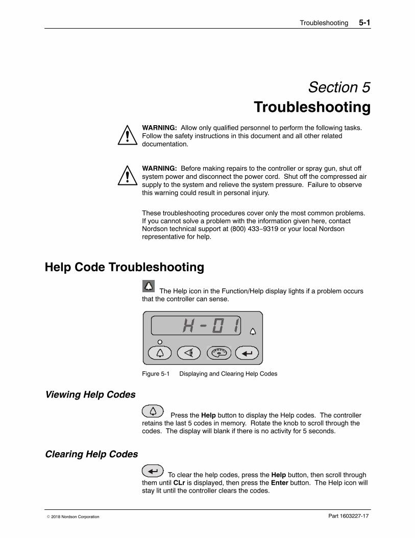
Troubleshooting 5-1
Part 1603227-17� 2018 Nordson Corporation
Section 5Troubleshooting
WARNING: Allow only qualified personnel to perform the following tasks.Follow the safety instructions in this document and all other relateddocumentation.
WARNING: Before making repairs to the controller or spray gun, shut offsystem power and disconnect the power cord. Shut off the compressed airsupply to the system and relieve the system pressure. Failure to observethis warning could result in personal injury.
These troubleshooting procedures cover only the most common problems.If you cannot solve a problem with the information given here, contactNordson technical support at (800) 433−9319 or your local Nordsonrepresentative for help.
Help Code Troubleshooting
The Help icon in the Function/Help display lights if a problem occursthat the controller can sense.
Figure 5-1 Displaying and Clearing Help Codes
Viewing Help Codes
Press the Help button to display the Help codes. The controllerretains the last 5 codes in memory. Rotate the knob to scroll through thecodes. The display will blank if there is no activity for 5 seconds.
Clearing Help Codes
To clear the help codes, press the Help button, then scroll throughthem until CLr is displayed, then press the Enter button. The Help icon willstay lit until the controller clears the codes.
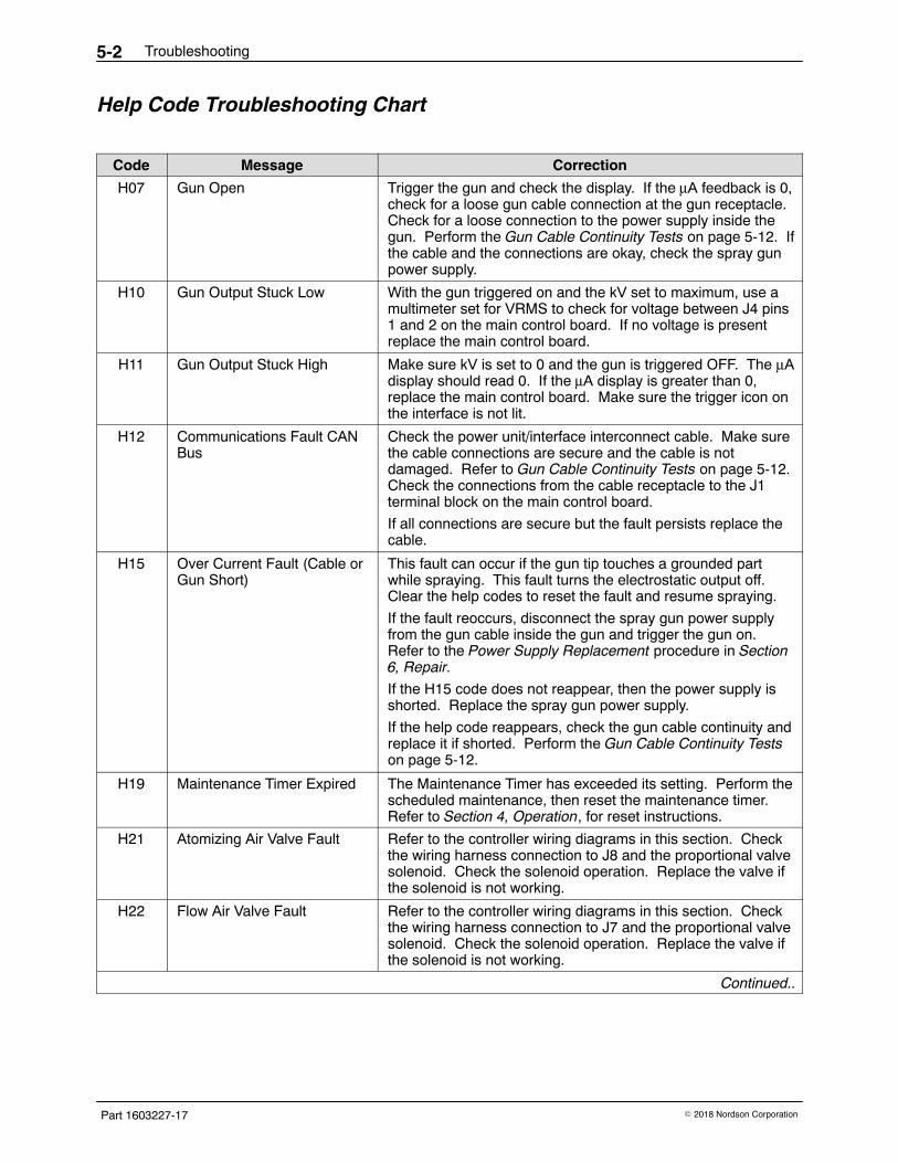
Troubleshooting5-2
Part 1603227-17 � 2018 Nordson Corporation
Help Code Troubleshooting Chart
Code Message Correction
H07 Gun Open Trigger the gun and check the display. If the μA feedback is 0,check for a loose gun cable connection at the gun receptacle.Check for a loose connection to the power supply inside thegun. Perform the Gun Cable Continuity Tests on page 5-12. Ifthe cable and the connections are okay, check the spray gunpower supply.
H10 Gun Output Stuck Low With the gun triggered on and the kV set to maximum, use amultimeter set for VRMS to check for voltage between J4 pins1 and 2 on the main control board. If no voltage is presentreplace the main control board.
H11 Gun Output Stuck High Make sure kV is set to 0 and the gun is triggered OFF. The μAdisplay should read 0. If the μA display is greater than 0,replace the main control board. Make sure the trigger icon onthe interface is not lit.
H12 Communications Fault CANBus
Check the power unit/interface interconnect cable. Make surethe cable connections are secure and the cable is notdamaged. Refer to Gun Cable Continuity Tests on page 5-12.Check the connections from the cable receptacle to the J1terminal block on the main control board.
If all connections are secure but the fault persists replace thecable.
H15 Over Current Fault (Cable orGun Short)
This fault can occur if the gun tip touches a grounded partwhile spraying. This fault turns the electrostatic output off.Clear the help codes to reset the fault and resume spraying.
If the fault reoccurs, disconnect the spray gun power supplyfrom the gun cable inside the gun and trigger the gun on.Refer to the Power Supply Replacement procedure in Section6, Repair.
If the H15 code does not reappear, then the power supply isshorted. Replace the spray gun power supply.
If the help code reappears, check the gun cable continuity andreplace it if shorted. Perform the Gun Cable Continuity Testson page 5-12.
H19 Maintenance Timer Expired The Maintenance Timer has exceeded its setting. Perform thescheduled maintenance, then reset the maintenance timer.Refer to Section 4, Operation, for reset instructions.
H21 Atomizing Air Valve Fault Refer to the controller wiring diagrams in this section. Checkthe wiring harness connection to J8 and the proportional valvesolenoid. Check the solenoid operation. Replace the valve ifthe solenoid is not working.
H22 Flow Air Valve Fault Refer to the controller wiring diagrams in this section. Checkthe wiring harness connection to J7 and the proportional valvesolenoid. Check the solenoid operation. Replace the valve ifthe solenoid is not working.
Continued..
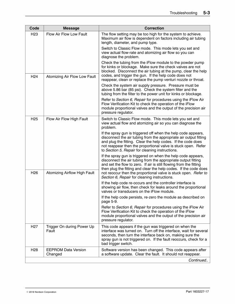
Troubleshooting 5-3
Part 1603227-17� 2018 Nordson Corporation
CorrectionMessageCode
H23 Flow Air Flow Low Fault The flow setting may be too high for the system to achieve.Maximum air flow is dependent on factors including air tubinglength, diameter, and pump type.
Switch to Classic Flow mode. This mode lets you set andview actual flow-rate and atomizing air flow so you candiagnose the problem.
Check the tubing from the iFlow module to the powder pumpfor kinks or blockage. Make sure the check valves are notblocked. Disconnect the air tubing at the pump, clear the helpcodes, and trigger the gun. If the help code does notreappear, clean or replace the pump venturi nozzle or throat.
Check the system air supply pressure. Pressure must beabove 5.86 bar (85 psi). Check the system filter and thetubing from the filter to the power unit for kinks or blockage.
Refer to Section 6, Repair for procedures using the iFlow AirFlow Verification Kit to check the operation of the iFlowmodule proportional valves and the output of the precision airpressure regulator.
H24 Atomizing Air Flow Low Fault
H25 Flow Air Flow High Fault Switch to Classic Flow mode. This mode lets you set andview actual flow and atomizing air so you can diagnose theproblem.
If the spray gun is triggered off when the help code appears,disconnect the air tubing from the appropriate air output fittingand plug the fitting. Clear the help codes. If the code doesnot reappear then the proportional valve is stuck open. Referto Section 5, Repair for cleaning instructions.
If the spray gun is triggered on when the help code appears,disconnect the air tubing from the appropriate output fittingand set the flow to zero. If air is still flowing from the fittingthen plug the fitting and clear the help codes. If the code doesnot reoccur then the proportional valve is stuck open. Refer toSection 6, Repair for cleaning instructions.
If the help code re-occurs and the controller interface isshowing air flow, then check for leaks around the proportionalvalves or transducers on the iFlow module.
If the help code persists, re-zero the module as described onpage 5-9.
Refer to Section 6, Repair for procedures using the iFlow AirFlow Verification Kit to check the operation of the iFlowmodule proportional valves and the output of the precision airpressure regulator.
H26 Atomizing Airflow High Fault
H27 Trigger On during Power UpFault
This code appears if the gun was triggered on when theinterface was turned on. Turn off the interface, wait for severalseconds, then turn the interface back on, making sure thespray gun is not triggered on. If the fault reoccurs, check for abad trigger switch.
H28 EEPROM Data VersionChanged
Software version has been changed. This code appears aftera software update. Clear the fault. It should not reappear.
Continued..
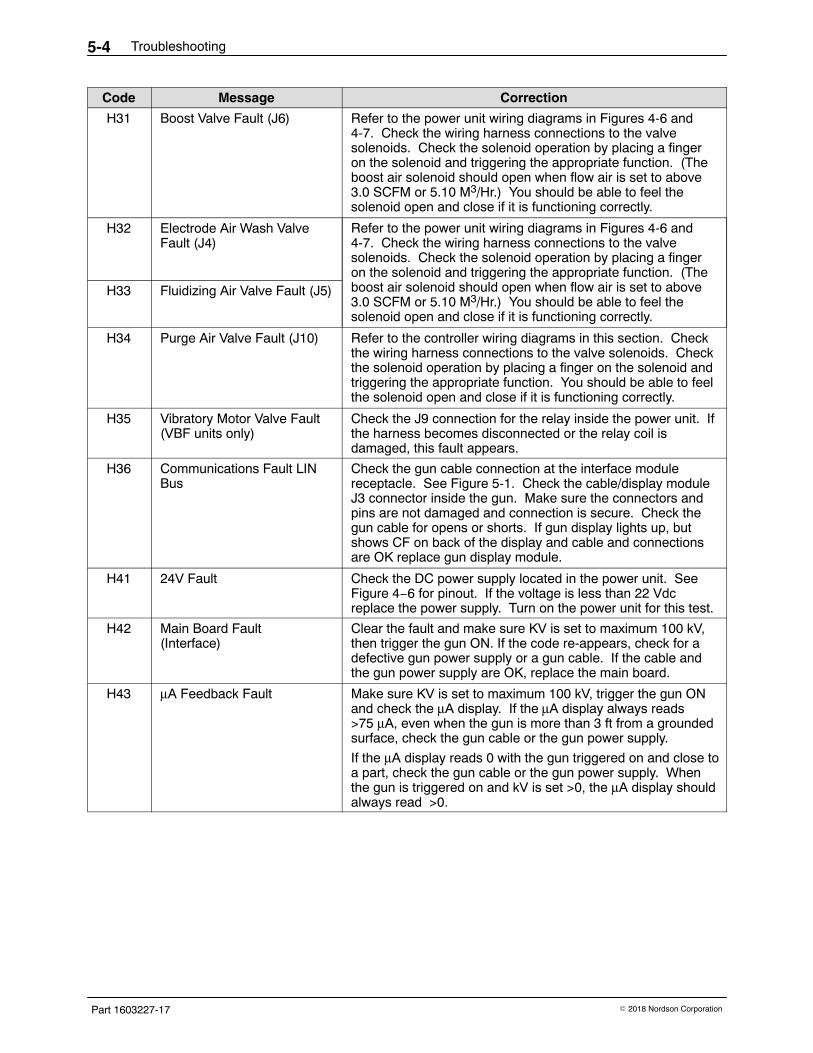
Troubleshooting5-4
Part 1603227-17 � 2018 Nordson Corporation
CorrectionMessageCode
H31 Boost Valve Fault (J6) Refer to the power unit wiring diagrams in Figures 4-6 and4-7. Check the wiring harness connections to the valvesolenoids. Check the solenoid operation by placing a fingeron the solenoid and triggering the appropriate function. (Theboost air solenoid should open when flow air is set to above3.0 SCFM or 5.10 M3/Hr.) You should be able to feel thesolenoid open and close if it is functioning correctly.
H32 Electrode Air Wash ValveFault (J4)
Refer to the power unit wiring diagrams in Figures 4-6 and4-7. Check the wiring harness connections to the valvesolenoids. Check the solenoid operation by placing a fingeron the solenoid and triggering the appropriate function. (Theboost air solenoid should open when flow air is set to above3.0 SCFM or 5.10 M3/Hr.) You should be able to feel thesolenoid open and close if it is functioning correctly.
H33 Fluidizing Air Valve Fault (J5)
H34 Purge Air Valve Fault (J10) Refer to the controller wiring diagrams in this section. Checkthe wiring harness connections to the valve solenoids. Checkthe solenoid operation by placing a finger on the solenoid andtriggering the appropriate function. You should be able to feelthe solenoid open and close if it is functioning correctly.
H35 Vibratory Motor Valve Fault(VBF units only)
Check the J9 connection for the relay inside the power unit. Ifthe harness becomes disconnected or the relay coil isdamaged, this fault appears.
H36 Communications Fault LINBus
Check the gun cable connection at the interface modulereceptacle. See Figure 5-1. Check the cable/display moduleJ3 connector inside the gun. Make sure the connectors andpins are not damaged and connection is secure. Check thegun cable for opens or shorts. If gun display lights up, butshows CF on back of the display and cable and connectionsare OK replace gun display module.
H41 24V Fault Check the DC power supply located in the power unit. SeeFigure 4−6 for pinout. If the voltage is less than 22 Vdcreplace the power supply. Turn on the power unit for this test.
H42 Main Board Fault(Interface)
Clear the fault and make sure KV is set to maximum 100 kV,then trigger the gun ON. If the code re-appears, check for adefective gun power supply or a gun cable. If the cable andthe gun power supply are OK, replace the main board.
H43 μA Feedback Fault Make sure KV is set to maximum 100 kV, trigger the gun ONand check the μA display. If the μA display always reads>75 μA, even when the gun is more than 3 ft from a groundedsurface, check the gun cable or the gun power supply.
If the μA display reads 0 with the gun triggered on and close toa part, check the gun cable or the gun power supply. Whenthe gun is triggered on and kV is set >0, the μA display shouldalways read >0.
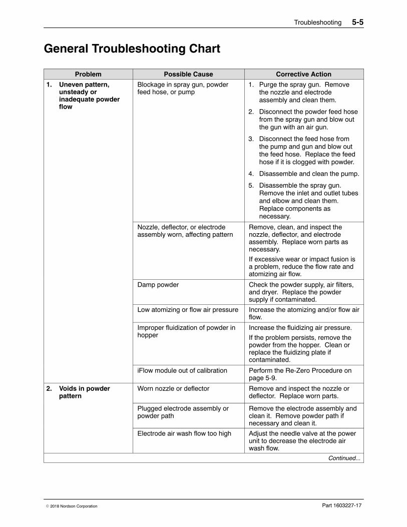
Troubleshooting 5-5
Part 1603227-17� 2018 Nordson Corporation
General Troubleshooting Chart
Problem Possible Cause Corrective Action
1. Uneven pattern,unsteady orinadequate powderflow
Blockage in spray gun, powderfeed hose, or pump
1. Purge the spray gun. Removethe nozzle and electrodeassembly and clean them.
2. Disconnect the powder feed hosefrom the spray gun and blow outthe gun with an air gun.
3. Disconnect the feed hose fromthe pump and gun and blow outthe feed hose. Replace the feedhose if it is clogged with powder.
4. Disassemble and clean the pump.
5. Disassemble the spray gun.Remove the inlet and outlet tubesand elbow and clean them.Replace components asnecessary.
Nozzle, deflector, or electrodeassembly worn, affecting pattern
Remove, clean, and inspect thenozzle, deflector, and electrodeassembly. Replace worn parts asnecessary.
If excessive wear or impact fusion isa problem, reduce the flow rate andatomizing air flow.
Damp powder Check the powder supply, air filters,and dryer. Replace the powdersupply if contaminated.
Low atomizing or flow air pressure Increase the atomizing and/or flow airflow.
Improper fluidization of powder inhopper
Increase the fluidizing air pressure.
If the problem persists, remove thepowder from the hopper. Clean orreplace the fluidizing plate ifcontaminated.
iFlow module out of calibration Perform the Re-Zero Procedure onpage 5-9.
2. Voids in powderpattern
Worn nozzle or deflector Remove and inspect the nozzle ordeflector. Replace worn parts.
Plugged electrode assembly orpowder path
Remove the electrode assembly andclean it. Remove powder path ifnecessary and clean it.
Electrode air wash flow too high Adjust the needle valve at the powerunit to decrease the electrode airwash flow.
Continued...
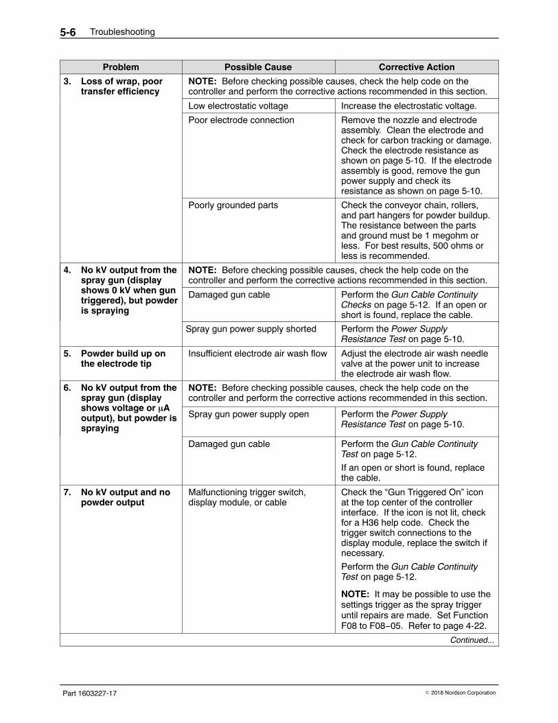
Troubleshooting5-6
Part 1603227-17 � 2018 Nordson Corporation
Corrective ActionPossible CauseProblem
3. Loss of wrap, poortransfer efficiency
NOTE: Before checking possible causes, check the help code on thecontroller and perform the corrective actions recommended in this section.
Low electrostatic voltage Increase the electrostatic voltage.
Poor electrode connection Remove the nozzle and electrodeassembly. Clean the electrode andcheck for carbon tracking or damage.Check the electrode resistance asshown on page 5-10. If the electrodeassembly is good, remove the gunpower supply and check itsresistance as shown on page 5-10.
Poorly grounded parts Check the conveyor chain, rollers,and part hangers for powder buildup.The resistance between the partsand ground must be 1 megohm orless. For best results, 500 ohms orless is recommended.
4. No kV output from thespray gun (displayshows 0 kV when guntriggered), but powderis spraying
NOTE: Before checking possible causes, check the help code on thecontroller and perform the corrective actions recommended in this section.
Damaged gun cable Perform the Gun Cable ContinuityChecks on page 5-12. If an open orshort is found, replace the cable.
Spray gun power supply shorted Perform the Power SupplyResistance Test on page 5-10.
5. Powder build up onthe electrode tip
Insufficient electrode air wash flow Adjust the electrode air wash needlevalve at the power unit to increasethe electrode air wash flow.
6. No kV output from thespray gun (displayshows voltage or �Aoutput), but powder isspraying
NOTE: Before checking possible causes, check the help code on thecontroller and perform the corrective actions recommended in this section.
Spray gun power supply open Perform the Power SupplyResistance Test on page 5-10.
Damaged gun cable Perform the Gun Cable ContinuityTest on page 5-12.
If an open or short is found, replacethe cable.
7. No kV output and nopowder output
Malfunctioning trigger switch,display module, or cable
Check the “Gun Triggered On” iconat the top center of the controllerinterface. If the icon is not lit, checkfor a H36 help code. Check thetrigger switch connections to thedisplay module, replace the switch ifnecessary.
Perform the Gun Cable ContinuityTest on page 5-12.
NOTE: It may be possible to use thesettings trigger as the spray triggeruntil repairs are made. Set FunctionF08 to F08−05. Refer to page 4-22.
Continued...
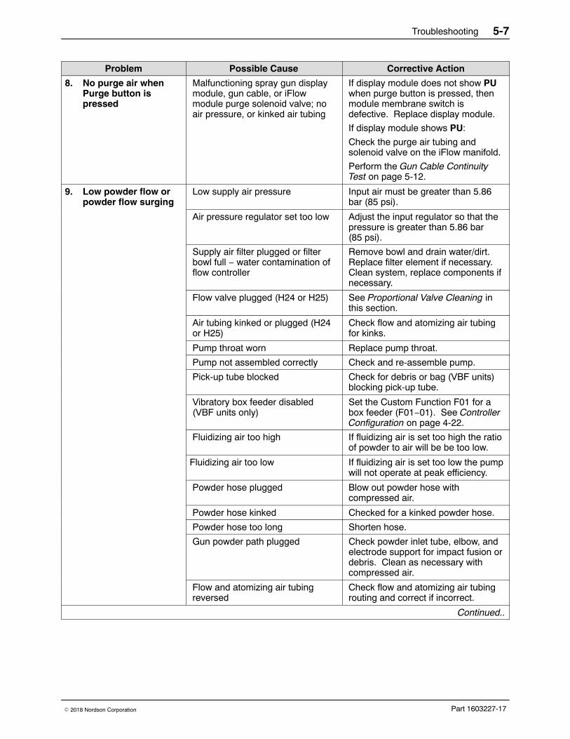
Troubleshooting 5-7
Part 1603227-17� 2018 Nordson Corporation
Corrective ActionPossible CauseProblem
8. No purge air whenPurge button ispressed
Malfunctioning spray gun displaymodule, gun cable, or iFlowmodule purge solenoid valve; noair pressure, or kinked air tubing
If display module does not show PUwhen purge button is pressed, thenmodule membrane switch isdefective. Replace display module.
If display module shows PU:
Check the purge air tubing andsolenoid valve on the iFlow manifold.
Perform the Gun Cable ContinuityTest on page 5-12.
9. Low powder flow orpowder flow surging
Low supply air pressure Input air must be greater than 5.86bar (85 psi).
Air pressure regulator set too low Adjust the input regulator so that thepressure is greater than 5.86 bar(85 psi).
Supply air filter plugged or filterbowl full − water contamination offlow controller
Remove bowl and drain water/dirt.Replace filter element if necessary.Clean system, replace components ifnecessary.
Flow valve plugged (H24 or H25) See Proportional Valve Cleaning inthis section.
Air tubing kinked or plugged (H24or H25)
Check flow and atomizing air tubingfor kinks.
Pump throat worn Replace pump throat.
Pump not assembled correctly Check and re-assemble pump.
Pick-up tube blocked Check for debris or bag (VBF units)blocking pick-up tube.
Vibratory box feeder disabled(VBF units only)
Set the Custom Function F01 for abox feeder (F01−01). See ControllerConfiguration on page 4-22.
Fluidizing air too high If fluidizing air is set too high the ratioof powder to air will be be too low.
Fluidizing air too low If fluidizing air is set too low the pumpwill not operate at peak efficiency.
Powder hose plugged Blow out powder hose withcompressed air.
Powder hose kinked Checked for a kinked powder hose.
Powder hose too long Shorten hose.
Gun powder path plugged Check powder inlet tube, elbow, andelectrode support for impact fusion ordebris. Clean as necessary withcompressed air.
Flow and atomizing air tubingreversed
Check flow and atomizing air tubingrouting and correct if incorrect.
Continued..
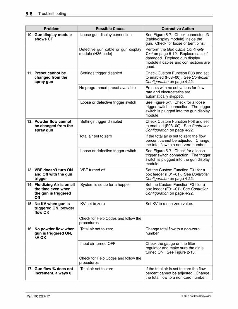
Troubleshooting5-8
Part 1603227-17 � 2018 Nordson Corporation
Corrective ActionPossible CauseProblem
10. Gun display moduleshows CF
Loose gun display connection See Figure 5-7. Check connector J3(cable/display module) inside thegun. Check for loose or bent pins.
Defective gun cable or gun displaymodule (H36 code)
Perform the Gun Cable ContinuityTest on page 5-12. Replace cable ifdamaged. Replace gun displaymodule if cables and connections aregood.
11. Preset cannot bechanged from thespray gun
Settings trigger disabled Check Custom Function F08 and setto enabled (F08−00). See ControllerConfiguration on page 4-22.
No programmed preset available Presets with no set values for flowrate and electrostatics areautomatically skipped.
Loose or defective trigger switch See Figure 5-7. Check for a loosetrigger switch connection. The triggerswitch is plugged into the gun displaymodule.
12. Powder flow cannotbe changed from thespray gun
Settings trigger disabled Check Custom Function F08 and setto enabled (F08−00). See ControllerConfiguration on page 4-22.
Total air set to zero If the total air is set to zero the flowpercent cannot be adjusted. Changethe total flow to a non-zero number.
Loose or defective trigger switch See Figure 5-7. Check for a loosetrigger switch connection. The triggerswitch is plugged into the gun displaymodule.
13. VBF doesn’t turn ONand Off with the guntrigger
VBF turned off Set the Custom Function F01 for abox feeder (F01−01). See ControllerConfiguration on page 4-22.
14. Fluidizing Air is on allthe time even whenthe gun is triggeredOff
System is setup for a hopper Set the Custom Function F01 for abox feeder (F01−01). See ControllerConfiguration on page 4-22.
15. No KV when gun istriggered ON, powderflow OK
KV set to zero Set KV to a non-zero value.
Check for Help Codes and follow theprocedures
16. No powder flow whengun is triggered ON,kV OK
Total air set to zero Change total flow to a non-zeronumber.
Input air turned OFF Check the gauge on the filterregulator and make sure the air isturned ON. See Figure 2-13.
Check for Help Codes and follow theprocedures
17. Gun flow % does notincrement, always 0
Total air set to zero If the total air is set to zero the flowpercent cannot be adjusted. Changethe total flow to a non-zero number.
Troubleshooting 5-9
Part 1603227-17� 2018 Nordson Corporation
Re-Zero Procedure Perform this procedure if the controller interface indicates air flow when thespray gun is not triggered on, or if a Flow Air or Atomizing Air Flow HighHelp code (H25 or H26) appears.
NOTE: Before performing a re-zero procedure:
� Make sure the air pressure being supplied to the system is higherthan the minimum 5.86 bar (85 psi).
� Make sure no air is leaking through the module output fittings orfrom around the solenoid valves or proportional valves.Re-zeroing modules with leaks will result in additional errors.
1. At the power unit, disconnect the flow and atomizing air tubing andinstall 8-mm plugs in the output fittings.
2. Press the Nordson button for 5 seconds to display the controllerfunctions. F00−00 is displayed.
3. Rotate the knob until F10−00 is displayed.
4. Press the Enter button, then rotate the knob to display F10−01.
5. Press the Enter button. The controller will re-zero the flow andatomizing air and reset the function display to F10−00.
6. Remove the plugs from the flow and atomizing air output fittings andreconnect the air tubing.
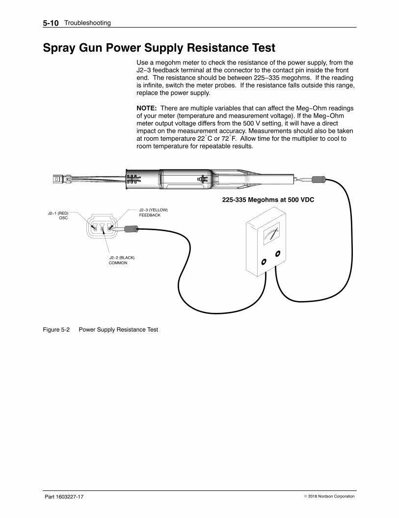
Troubleshooting5-10
Part 1603227-17 � 2018 Nordson Corporation
Spray Gun Power Supply Resistance Test Use a megohm meter to check the resistance of the power supply, from theJ2−3 feedback terminal at the connector to the contact pin inside the frontend. The resistance should be between 225−335 megohms. If the readingis infinite, switch the meter probes. If the resistance falls outside this range,replace the power supply.
NOTE: There are multiple variables that can affect the Meg−Ohm readingsof your meter (temperature and measurement voltage). If the Meg−Ohmmeter output voltage differs from the 500 V setting, it will have a directimpact on the measurement accuracy. Measurements should also be takenat room temperature 22�C or 72�F. Allow time for the multiplier to cool toroom temperature for repeatable results.
J2−3 (YELLOW)FEEDBACK
J2−2 (BLACK)COMMON
J2−1 (RED)OSC
225-335 Megohms at 500 VDC
Figure 5-2 Power Supply Resistance Test
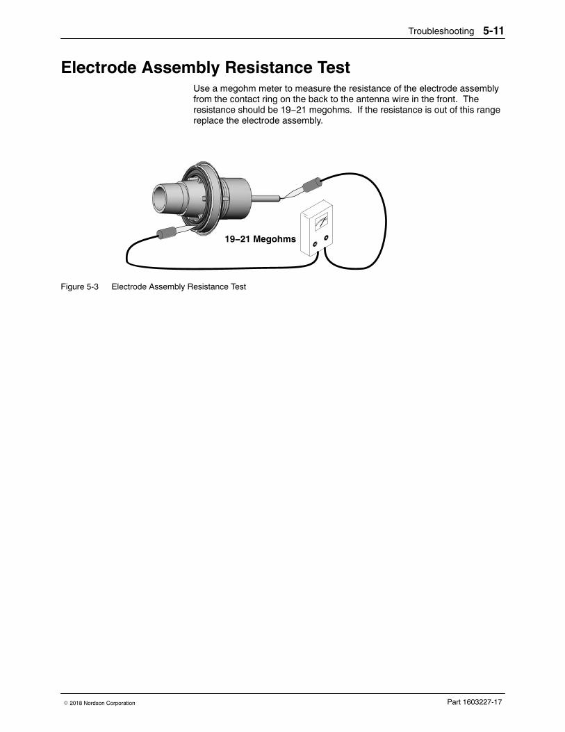
Troubleshooting 5-11
Part 1603227-17� 2018 Nordson Corporation
Electrode Assembly Resistance Test Use a megohm meter to measure the resistance of the electrode assemblyfrom the contact ring on the back to the antenna wire in the front. Theresistance should be 19−21 megohms. If the resistance is out of this rangereplace the electrode assembly.
19−21 Megohms
Figure 5-3 Electrode Assembly Resistance Test
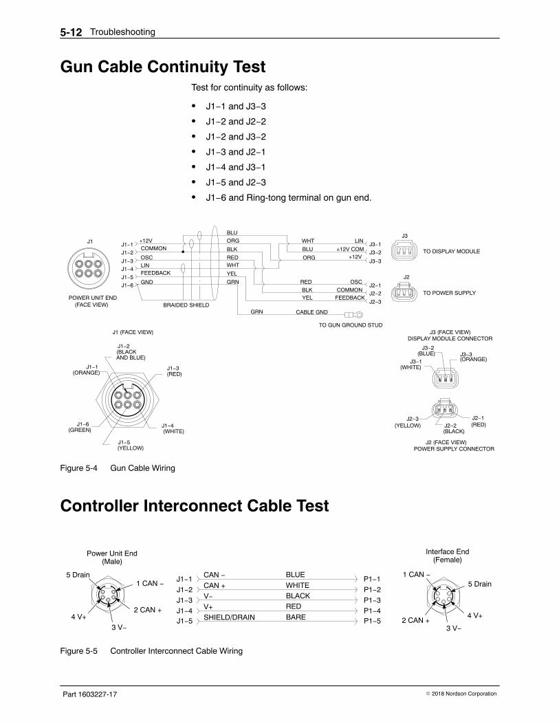
Troubleshooting5-12
Part 1603227-17 � 2018 Nordson Corporation
Gun Cable Continuity Test Test for continuity as follows:
� J1−1 and J3−3
� J1−2 and J2−2
� J1−2 and J3−2
� J1−3 and J2−1
� J1−4 and J3−1
� J1−5 and J2−3
� J1−6 and Ring-tong terminal on gun end.
+12V LINCOMMON
OSC
OSC
LIN
COMMON
+12V COMJ1−1
J1−2
J1−3
J1−4
J1−5
J1−6
FEEDBACK
GND
BRAIDED SHIELD
GRN
WHT
CABLE GNDGRN
BLK
RED
J2−2
J2−1
RED
BLK
ORG
BLU
WHTJ3−1
J3−2
YEL
J3−3+12VORG
J2−3FEEDBACKYEL
BLU
J1−1(ORANGE)
J1−3(RED)
J1−6(GREEN)
J1−5(YELLOW)
J1−4(WHITE)
J1 (FACE VIEW)
J1−2(BLACKAND BLUE)
J1
POWER UNIT END(FACE VIEW)
J3
J3 (FACE VIEW)DISPLAY MODULE CONNECTOR
J3−1(WHITE)
J3−2(BLUE) J3−3
(ORANGE)
J2 (FACE VIEW)POWER SUPPLY CONNECTOR
J2−3(YELLOW)
J2−1(RED)J2−2
(BLACK)
J2
TO DISPLAY MODULE
TO POWER SUPPLY
TO GUN GROUND STUD
Figure 5-4 Gun Cable Wiring
Controller Interconnect Cable Test
CAN −
CAN +
V−
V+
SHIELD/DRAIN
J1−1
J1−2
J1−3J1−4J1−5
BLUE
WHITEBLACKRED
BARE
5 Drain1 CAN −
2 CAN +
3 V−4 V+
P1−3
P1−5P1−4
P1−1
P1−25 Drain
4 V+
1 CAN −
2 CAN +3 V−
Power Unit End(Male)
Interface End(Female)
Figure 5-5 Controller Interconnect Cable Wiring
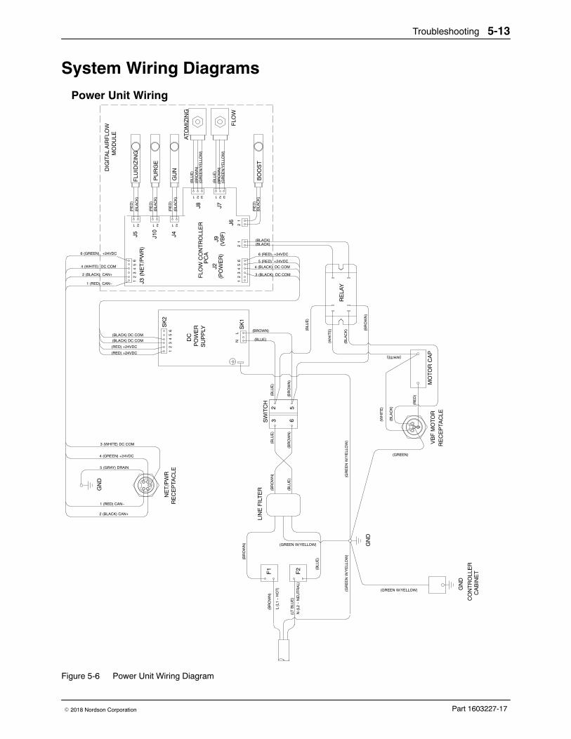
Troubleshooting 5-13
Part 1603227-17� 2018 Nordson Corporation
System Wiring Diagrams
N (
L2 −
NE
UT
RA
L)
(LT
BLU
E)
F2
F1
(BR
OW
N)
(BLU
E)
(BR
OW
N)
L (L
1 −
HO
T)
GN
D
(GR
EE
N W
/YE
LLO
W)
(GREEN W/YELLOW)
56
23
SK
21
SK
1
(BR
OW
N)
(BLU
E)
(BR
OW
N)
(BLU
E)
(GR
EE
N W
/YE
LLO
W)
RE
LAY
(BR
OW
N)
(BLU
E)
(RE
D)
(BLA
CK
)
(WH
ITE
)(WHITE)
5 (RED) +24VDC
4 (BLACK) DC COM
3 (BLACK) DC COM
6 (RED) +24VDC
21
43
56
(GREEN)
(BLU
E)
(BR
OW
N)
21
J6 21
(BLACK)(BLACK)
(RED) +24VDC
(BLACK) DC COM DC
PO
WE
RS
UP
PLY
(BLUE)
(BROWN)
23
45
6
62
13
45
J3 (
NE
T/P
WR
)
2 (BLACK) CAN+
1 (RED) CAN−
6 (GREEN) +24VDC
4 (WHITE) DC COM
1 (RED) CAN−
2 (BLACK) CAN+
4 (GREEN) +24VDC
3 (WHITE) DC COM
5 (GRAY) DRAIN
GN
D
FLO
W C
ON
TR
OLL
ER
PC
A
21
J10
J7
321
J8
321
J4
21
J5
21
NE
T/P
WR
RE
CE
PTA
CLE
VB
F M
OT
OR
RE
CE
PTA
CLE
GN
D
(BLA
CK
)(R
ED
)
PU
RG
E
(BLA
CK
)(R
ED
)F
LUID
IZIN
G
(BLA
CK
)(R
ED
)G
UN
BO
OS
T(B
LAC
K)
(RE
D)
(BR
OW
N)
(BLU
E)
(GR
EE
N/Y
ELL
OW
)
(GR
EE
N/Y
ELL
OW
)(B
RO
WN
)(B
LUE
)
AT
OM
IZIN
G
FLO
W
DIG
ITA
L A
IRF
LOW
MO
DU
LE
CO
NT
RO
LLE
RC
AB
INE
T
SW
ITC
H
(GREEN W/YELLOW)
LN (W
HIT
E)
(BLA
CK
)
MO
TO
R C
AP
LIN
E F
ILT
ER
(RED) +24VDC
(BLACK) DC COM
J2(P
OW
ER
)J9
(VB
F)
Power Unit Wiring
Figure 5-6 Power Unit Wiring Diagram
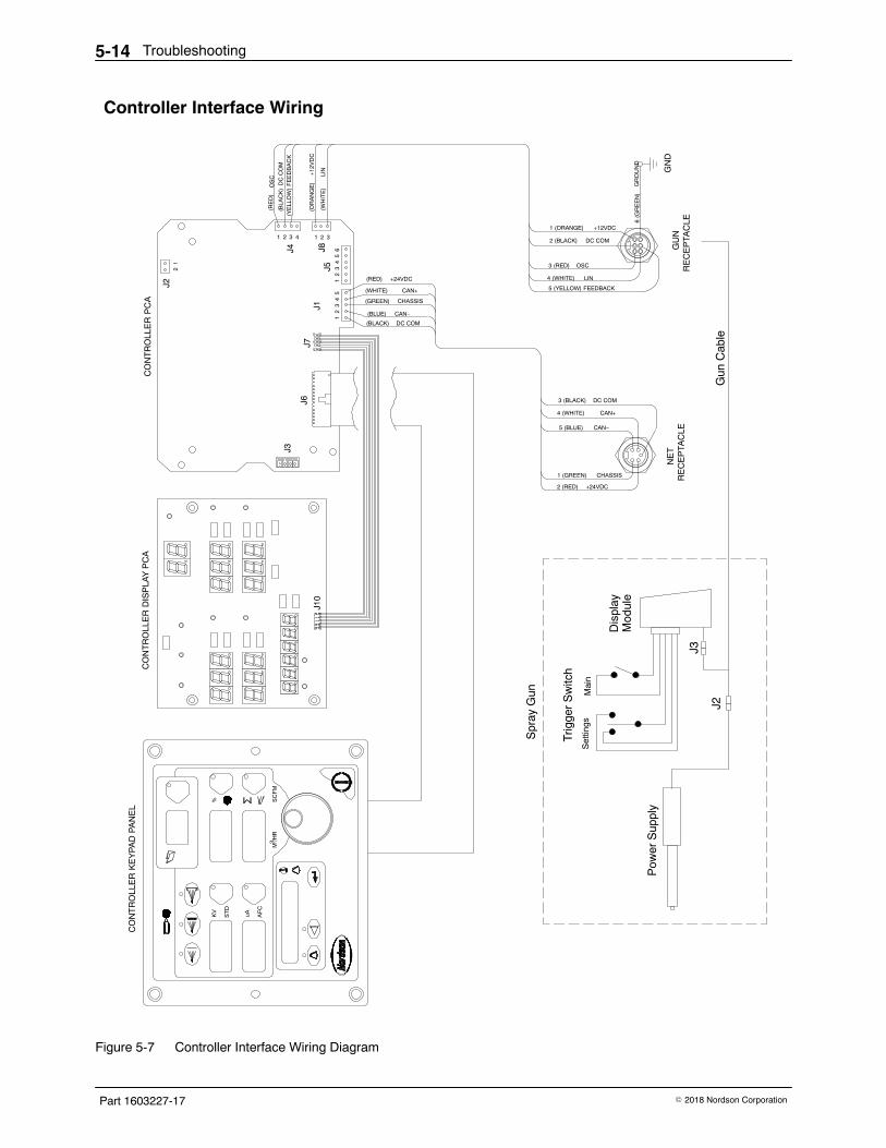
Troubleshooting5-14
Part 1603227-17 � 2018 Nordson Corporation
% SC
FM
AF
C
uAST
D
KV
M /H
R3
4321
J4
DC COM
CAN+
CHASSIS
+24VDC
CAN−
14
35
2J1
1 2 3
(BLACK)
(BLUE)
(GREEN)
(WHITE)
(RED)
GN
D
2 (RED)
1 (GREEN)
3 (BLACK)
5 (BLUE)
4 (WHITE)
CHASSIS
+24VDC
DC COM
CAN−
CAN+
1 (ORANGE)
6 (G
RE
EN
)
5 (YELLOW)
+12VDC
GR
OU
ND
FEEDBACK
4 (WHITE)
3 (RED)
LIN
OSC
2 (BLACK) DC COM
J6J7
J2
J3
12
(BLA
CK
)D
C C
OM
(RE
D)
OS
C
(WH
ITE
)LI
N
(YE
LLO
W)
FE
ED
BA
CK
(OR
AN
GE
)+
12V
DC
NE
TR
EC
EP
TAC
LEG
UN
RE
CE
PTA
CLE
CO
NT
RO
LLE
R P
CA
CO
NT
RO
LLE
R K
EY
PA
D P
AN
EL
CO
NT
RO
LLE
R D
ISP
LAY
PC
A
J10
1
J52
43
56J8
Pow
er S
uppl
y
Trig
ger
Sw
itch
Mai
nS
ettin
gs
Dis
play
Mod
ule
Spr
ay G
un
Gun
Cab
le
Controller Interface Wiring
J2
J3
Figure 5-7 Controller Interface Wiring Diagram
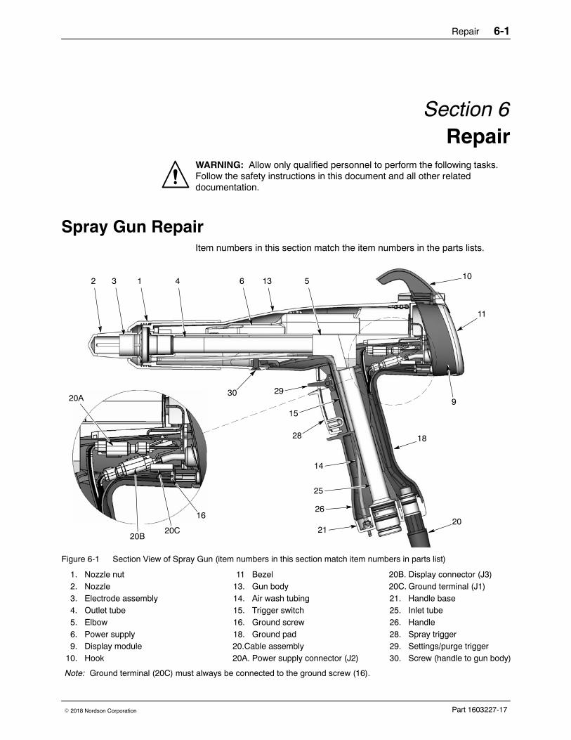
Repair 6-1
Part 1603227-17� 2018 Nordson Corporation
Section 6Repair
WARNING: Allow only qualified personnel to perform the following tasks.Follow the safety instructions in this document and all other relateddocumentation.
Spray Gun Repair Item numbers in this section match the item numbers in the parts lists.
2 3 1 64 5
14
15
29
20
9
11
10
21
28
25
26
13
18
3020A
20B20C
16
Figure 6-1 Section View of Spray Gun (item numbers in this section match item numbers in parts list)
1. Nozzle nut2. Nozzle3. Electrode assembly4. Outlet tube5. Elbow6. Power supply9. Display module
10. Hook
11 Bezel13. Gun body14. Air wash tubing15. Trigger switch16. Ground screw18. Ground pad20.Cable assembly20A. Power supply connector (J2)
20B. Display connector (J3)20C. Ground terminal (J1)21. Handle base25. Inlet tube26. Handle28. Spray trigger29. Settings/purge trigger30. Screw (handle to gun body)
Note: Ground terminal (20C) must always be connected to the ground screw (16).
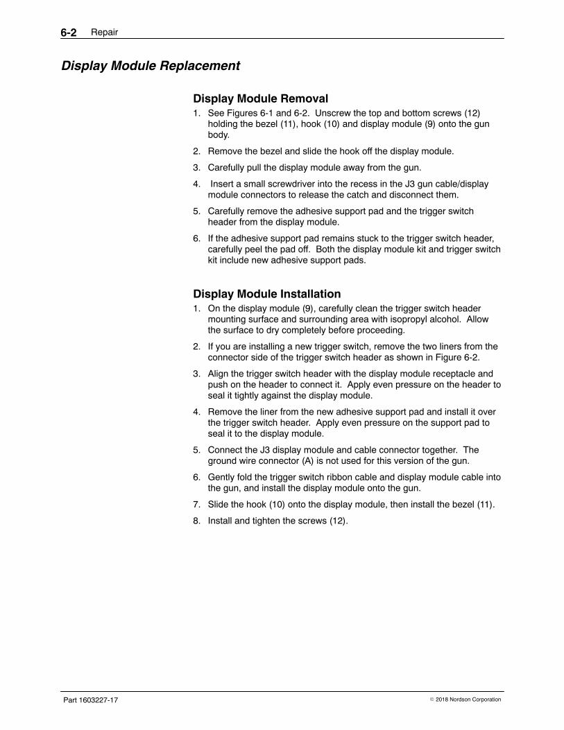
Repair6-2
Part 1603227-17 � 2018 Nordson Corporation
Display Module Replacement
Display Module Removal 1. See Figures 6-1 and 6-2. Unscrew the top and bottom screws (12)
holding the bezel (11), hook (10) and display module (9) onto the gunbody.
2. Remove the bezel and slide the hook off the display module.
3. Carefully pull the display module away from the gun.
4. Insert a small screwdriver into the recess in the J3 gun cable/displaymodule connectors to release the catch and disconnect them.
5. Carefully remove the adhesive support pad and the trigger switchheader from the display module.
6. If the adhesive support pad remains stuck to the trigger switch header,carefully peel the pad off. Both the display module kit and trigger switchkit include new adhesive support pads.
Display Module Installation 1. On the display module (9), carefully clean the trigger switch header
mounting surface and surrounding area with isopropyl alcohol. Allowthe surface to dry completely before proceeding.
2. If you are installing a new trigger switch, remove the two liners from theconnector side of the trigger switch header as shown in Figure 6-2.
3. Align the trigger switch header with the display module receptacle andpush on the header to connect it. Apply even pressure on the header toseal it tightly against the display module.
4. Remove the liner from the new adhesive support pad and install it overthe trigger switch header. Apply even pressure on the support pad toseal it to the display module.
5. Connect the J3 display module and cable connector together. Theground wire connector (A) is not used for this version of the gun.
6. Gently fold the trigger switch ribbon cable and display module cable intothe gun, and install the display module onto the gun.
7. Slide the hook (10) onto the display module, then install the bezel (11).
8. Install and tighten the screws (12).
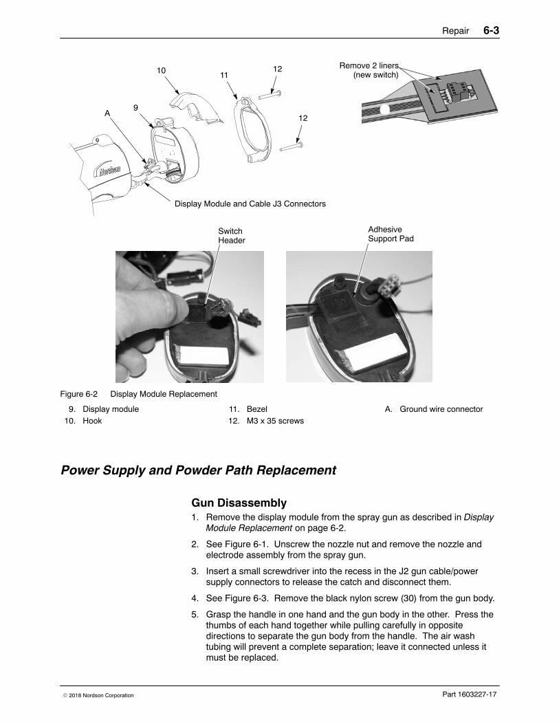
Repair 6-3
Part 1603227-17� 2018 Nordson Corporation
11
129
10
AdhesiveSupport Pad
SwitchHeader
Remove 2 liners(new switch)
12
Display Module and Cable J3 Connectors
A
Figure 6-2 Display Module Replacement
9. Display module10. Hook
11. Bezel12. M3 x 35 screws
A. Ground wire connector
Power Supply and Powder Path Replacement
Gun Disassembly 1. Remove the display module from the spray gun as described in Display
Module Replacement on page 6-2.
2. See Figure 6-1. Unscrew the nozzle nut and remove the nozzle andelectrode assembly from the spray gun.
3. Insert a small screwdriver into the recess in the J2 gun cable/powersupply connectors to release the catch and disconnect them.
4. See Figure 6-3. Remove the black nylon screw (30) from the gun body.
5. Grasp the handle in one hand and the gun body in the other. Press thethumbs of each hand together while pulling carefully in oppositedirections to separate the gun body from the handle. The air washtubing will prevent a complete separation; leave it connected unless itmust be replaced.
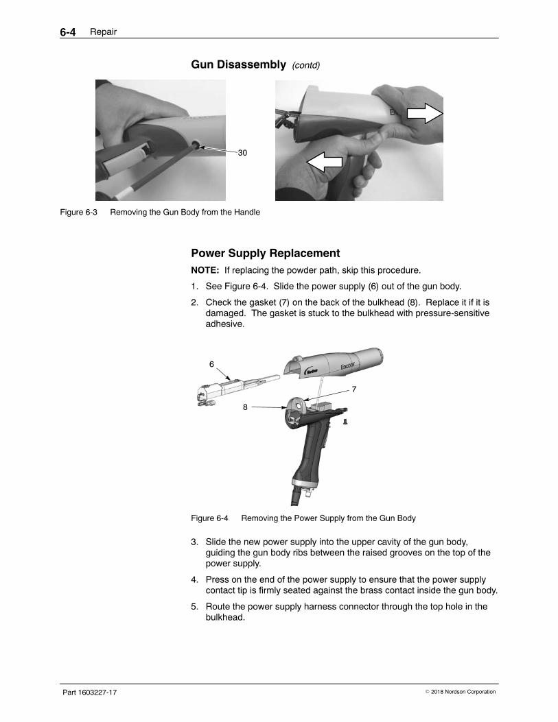
Repair6-4
Part 1603227-17 � 2018 Nordson Corporation
Gun Disassembly (contd)
30
Figure 6-3 Removing the Gun Body from the Handle
Power Supply Replacement NOTE: If replacing the powder path, skip this procedure.
1. See Figure 6-4. Slide the power supply (6) out of the gun body.
2. Check the gasket (7) on the back of the bulkhead (8). Replace it if it isdamaged. The gasket is stuck to the bulkhead with pressure-sensitiveadhesive.
6
7
8
Figure 6-4 Removing the Power Supply from the Gun Body
3. Slide the new power supply into the upper cavity of the gun body,guiding the gun body ribs between the raised grooves on the top of thepower supply.
4. Press on the end of the power supply to ensure that the power supplycontact tip is firmly seated against the brass contact inside the gun body.
5. Route the power supply harness connector through the top hole in thebulkhead.
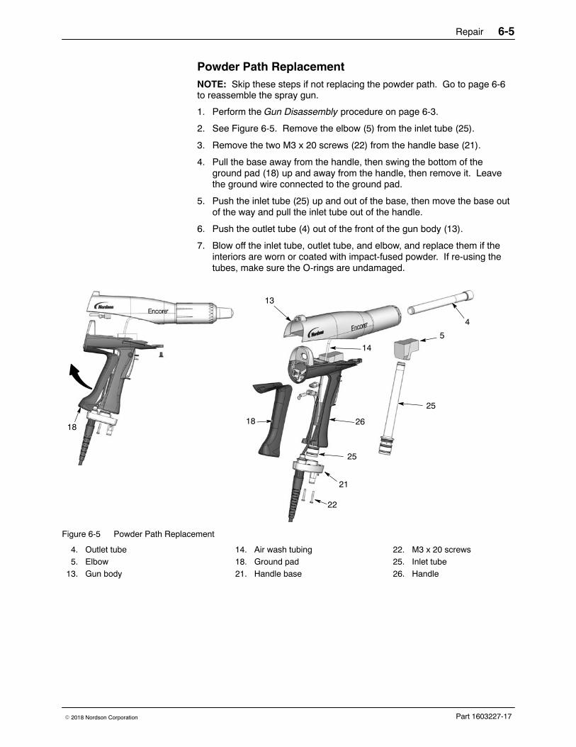
Repair 6-5
Part 1603227-17� 2018 Nordson Corporation
Powder Path Replacement NOTE: Skip these steps if not replacing the powder path. Go to page 6-6to reassemble the spray gun.
1. Perform the Gun Disassembly procedure on page 6-3.
2. See Figure 6-5. Remove the elbow (5) from the inlet tube (25).
3. Remove the two M3 x 20 screws (22) from the handle base (21).
4. Pull the base away from the handle, then swing the bottom of theground pad (18) up and away from the handle, then remove it. Leavethe ground wire connected to the ground pad.
5. Push the inlet tube (25) up and out of the base, then move the base outof the way and pull the inlet tube out of the handle.
6. Push the outlet tube (4) out of the front of the gun body (13).
7. Blow off the inlet tube, outlet tube, and elbow, and replace them if theinteriors are worn or coated with impact-fused powder. If re-using thetubes, make sure the O-rings are undamaged.
18
14
25
13
4
22
21
5
2618
25
Figure 6-5 Powder Path Replacement
4. Outlet tube5. Elbow
13. Gun body
14. Air wash tubing18. Ground pad21. Handle base
22. M3 x 20 screws25. Inlet tube26. Handle
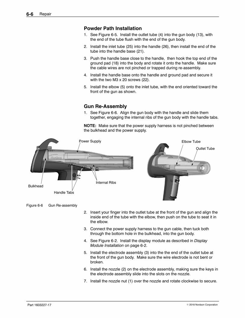
Repair6-6
Part 1603227-17 � 2018 Nordson Corporation
Powder Path Installation 1. See Figure 6-5. Install the outlet tube (4) into the gun body (13), with
the end of the tube flush with the end of the gun body.
2. Install the inlet tube (25) into the handle (26), then install the end of thetube into the handle base (21).
3. Push the handle base close to the handle, then hook the top end of theground pad (18) into the body and rotate it onto the handle. Make surethe cable wires are not pinched or trapped during re-assembly.
4. Install the handle base onto the handle and ground pad and secure itwith the two M3 x 20 screws (22).
5. Install the elbow (5) onto the inlet tube, with the end oriented toward thefront of the gun as shown.
Gun Re-Assembly 1. See Figure 6-6. Align the gun body with the handle and slide them
together, engaging the internal ribs of the gun body with the handle tabs.
NOTE: Make sure that the power supply harness is not pinched betweenthe bulkhead and the power supply.
Internal Ribs
Handle Tabs
Outlet Tube
Elbow TubePower Supply
Bulkhead
Figure 6-6 Gun Re-assembly
2. Insert your finger into the outlet tube at the front of the gun and align theinside end of the tube with the elbow, then push on the tube to seat it inthe elbow.
3. Connect the power supply harness to the gun cable, then tuck boththrough the bottom hole in the bulkhead, into the gun body.
4. See Figure 6-2. Install the display module as described in DisplayModule Installation on page 6-2.
5. Install the electrode assembly (3) into the the end of the outlet tube atthe front of the gun body. Make sure the wire electrode is not bent orbroken.
6. Install the nozzle (2) on the electrode assembly, making sure the keys inthe electrode assembly slide into the slots on the nozzle.
7. Install the nozzle nut (1) over the nozzle and rotate clockwise to secure.
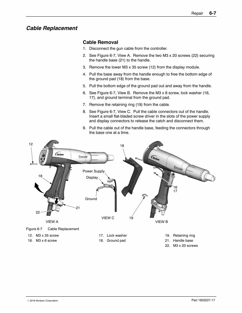
Repair 6-7
Part 1603227-17� 2018 Nordson Corporation
Cable Replacement
Cable Removal 1. Disconnect the gun cable from the controller.
2. See Figure 6-7, View A. Remove the two M3 x 20 screws (22) securingthe handle base (21) to the handle.
3. Remove the lower M3 x 35 screw (12) from the display module.
4. Pull the base away from the handle enough to free the bottom edge ofthe ground pad (18) from the base.
5. Pull the bottom edge of the ground pad out and away from the handle.
6. See Figure 6-7, View B. Remove the M3 x 8 screw, lock washer (16,17), and ground terminal from the ground pad.
7. Remove the retaining ring (19) from the cable.
8. See Figure 6-7, View C. Pull the cable connectors out of the handle.Insert a small flat-bladed screw driver in the slots of the power supplyand display connectors to release the catch and disconnect them.
9. Pull the cable out of the handle base, feeding the connectors throughthe base one at a time.
18
2221
19
16
18
VIEW A VIEW BVIEW C
17
Power Supply
Ground
Display
12
Figure 6-7 Cable Replacement
12. M3 x 35 screw16. M3 x 6 screw
17. Lock washer18. Ground pad
19. Retaining ring21. Handle base22. M3 x 20 screws
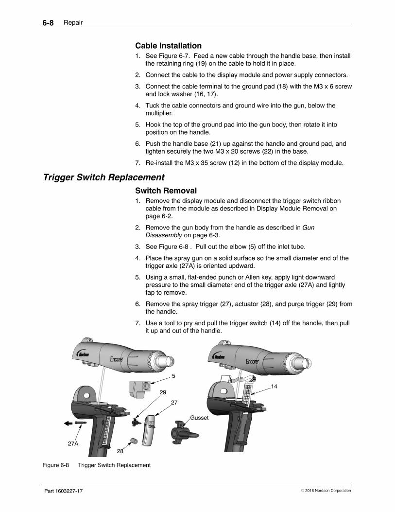
Repair6-8
Part 1603227-17 � 2018 Nordson Corporation
Cable Installation 1. See Figure 6-7. Feed a new cable through the handle base, then install
the retaining ring (19) on the cable to hold it in place.
2. Connect the cable to the display module and power supply connectors.
3. Connect the cable terminal to the ground pad (18) with the M3 x 6 screwand lock washer (16, 17).
4. Tuck the cable connectors and ground wire into the gun, below themultiplier.
5. Hook the top of the ground pad into the gun body, then rotate it intoposition on the handle.
6. Push the handle base (21) up against the handle and ground pad, andtighten securely the two M3 x 20 screws (22) in the base.
7. Re-install the M3 x 35 screw (12) in the bottom of the display module.
Trigger Switch Replacement Switch Removal 1. Remove the display module and disconnect the trigger switch ribbon
cable from the module as described in Display Module Removal onpage 6-2.
2. Remove the gun body from the handle as described in GunDisassembly on page 6-3.
3. See Figure 6-8 . Pull out the elbow (5) off the inlet tube.
4. Place the spray gun on a solid surface so the small diameter end of thetrigger axle (27A) is oriented updward.
5. Using a small, flat-ended punch or Allen key, apply light downwardpressure to the small diameter end of the trigger axle (27A) and lightlytap to remove.
6. Remove the spray trigger (27), actuator (28), and purge trigger (29) fromthe handle.
7. Use a tool to pry and pull the trigger switch (14) off the handle, then pullit up and out of the handle.
Gusset
29
27
28
5
27A
14
Figure 6-8 Trigger Switch Replacement
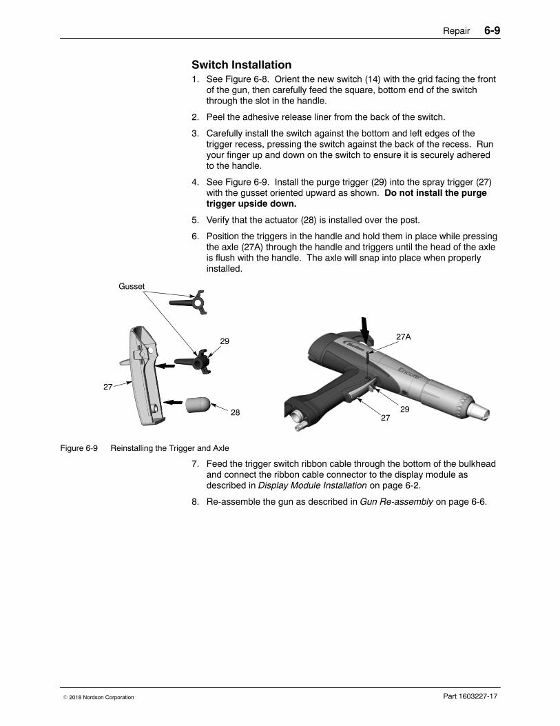
Repair 6-9
Part 1603227-17� 2018 Nordson Corporation
Switch Installation 1. See Figure 6-8. Orient the new switch (14) with the grid facing the front
of the gun, then carefully feed the square, bottom end of the switchthrough the slot in the handle.
2. Peel the adhesive release liner from the back of the switch.
3. Carefully install the switch against the bottom and left edges of thetrigger recess, pressing the switch against the back of the recess. Runyour finger up and down on the switch to ensure it is securely adheredto the handle.
4. See Figure 6-9. Install the purge trigger (29) into the spray trigger (27)with the gusset oriented upward as shown. Do not install the purgetrigger upside down.
5. Verify that the actuator (28) is installed over the post.
6. Position the triggers in the handle and hold them in place while pressingthe axle (27A) through the handle and triggers until the head of the axleis flush with the handle. The axle will snap into place when properlyinstalled.
27A
2729
27
28
29
Gusset
Figure 6-9 Reinstalling the Trigger and Axle
7. Feed the trigger switch ribbon cable through the bottom of the bulkheadand connect the ribbon cable connector to the display module asdescribed in Display Module Installation on page 6-2.
8. Re-assemble the gun as described in Gun Re-assembly on page 6-6.
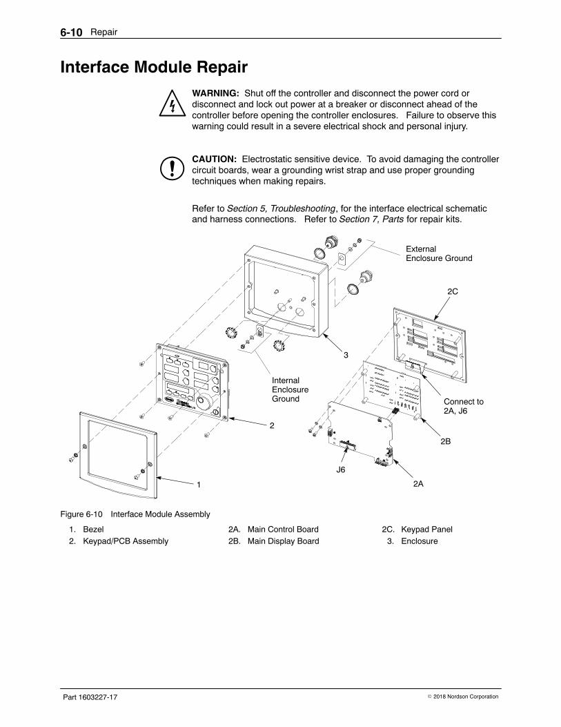
Repair6-10
Part 1603227-17 � 2018 Nordson Corporation
Interface Module Repair WARNING: Shut off the controller and disconnect the power cord ordisconnect and lock out power at a breaker or disconnect ahead of thecontroller before opening the controller enclosures. Failure to observe thiswarning could result in a severe electrical shock and personal injury.
CAUTION: Electrostatic sensitive device. To avoid damaging the controllercircuit boards, wear a grounding wrist strap and use proper groundingtechniques when making repairs.
Refer to Section 5, Troubleshooting, for the interface electrical schematicand harness connections. Refer to Section 7, Parts for repair kits.
1
2
3
2A
2B
2C
Connect to 2A, J6
InternalEnclosureGround
ExternalEnclosure Ground
J6
Figure 6-10 Interface Module Assembly
1. Bezel2. Keypad/PCB Assembly
2A. Main Control Board2B. Main Display Board
2C. Keypad Panel3. Enclosure
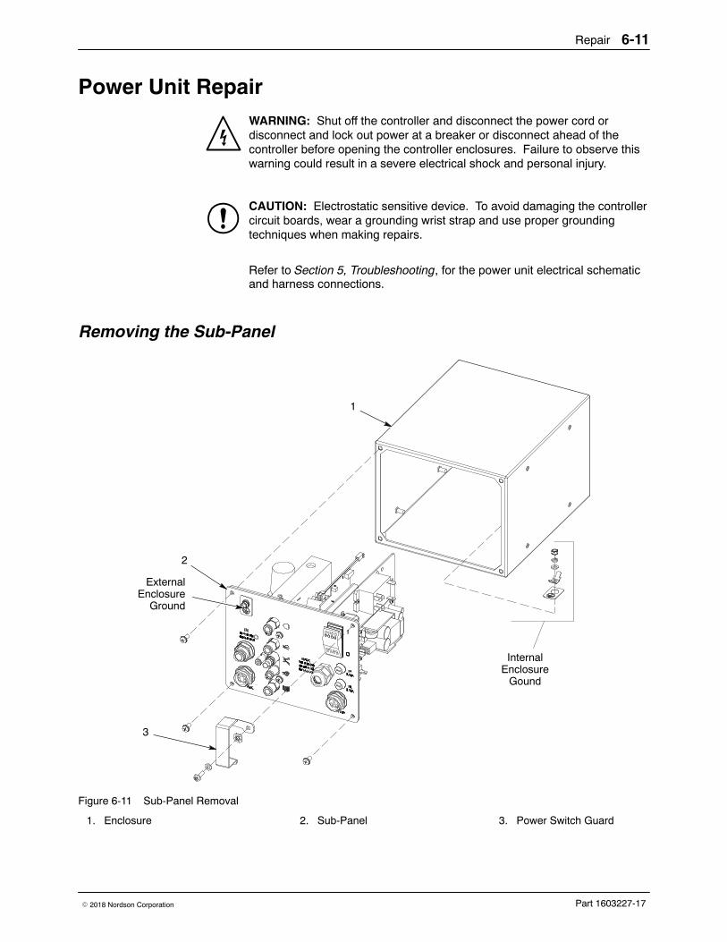
Repair 6-11
Part 1603227-17� 2018 Nordson Corporation
Power Unit Repair WARNING: Shut off the controller and disconnect the power cord ordisconnect and lock out power at a breaker or disconnect ahead of thecontroller before opening the controller enclosures. Failure to observe thiswarning could result in a severe electrical shock and personal injury.
CAUTION: Electrostatic sensitive device. To avoid damaging the controllercircuit boards, wear a grounding wrist strap and use proper groundingtechniques when making repairs.
Refer to Section 5, Troubleshooting, for the power unit electrical schematicand harness connections.
Removing the Sub-Panel
1
3
2
ExternalEnclosure
Ground
InternalEnclosure
Gound
Figure 6-11 Sub-Panel Removal
1. Enclosure 2. Sub-Panel 3. Power Switch Guard
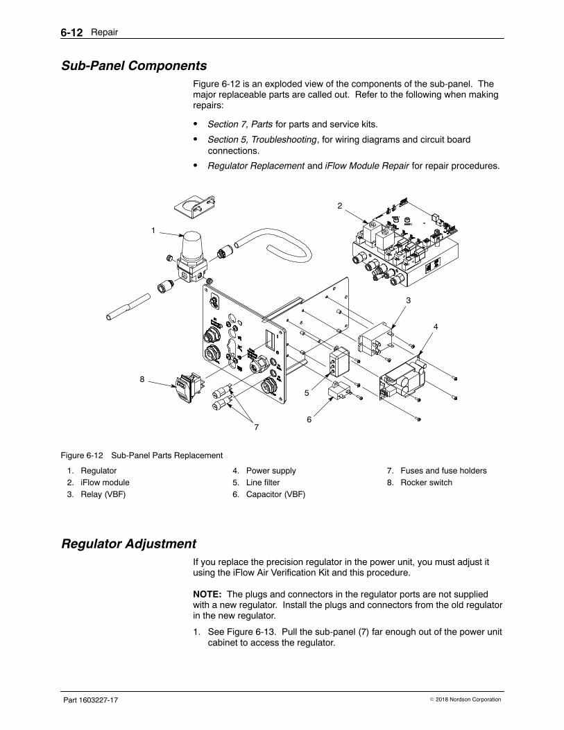
Repair6-12
Part 1603227-17 � 2018 Nordson Corporation
Sub-Panel Components Figure 6-12 is an exploded view of the components of the sub-panel. Themajor replaceable parts are called out. Refer to the following when makingrepairs:
� Section 7, Parts for parts and service kits.
� Section 5, Troubleshooting, for wiring diagrams and circuit boardconnections.
� Regulator Replacement and iFlow Module Repair for repair procedures.
3
4
2
1
6
5
7
8
Figure 6-12 Sub-Panel Parts Replacement
1. Regulator2. iFlow module3. Relay (VBF)
4. Power supply5. Line filter6. Capacitor (VBF)
7. Fuses and fuse holders8. Rocker switch
Regulator Adjustment If you replace the precision regulator in the power unit, you must adjust itusing the iFlow Air Verification Kit and this procedure.
NOTE: The plugs and connectors in the regulator ports are not suppliedwith a new regulator. Install the plugs and connectors from the old regulatorin the new regulator.
1. See Figure 6-13. Pull the sub-panel (7) far enough out of the power unitcabinet to access the regulator.
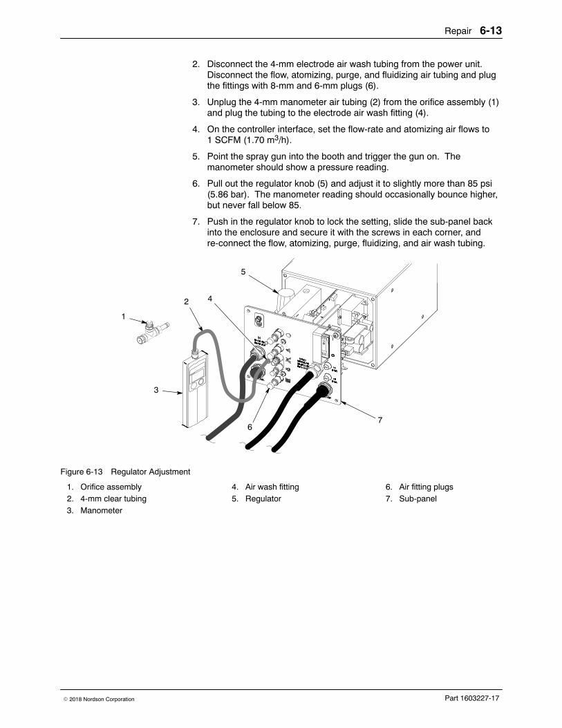
Repair 6-13
Part 1603227-17� 2018 Nordson Corporation
2. Disconnect the 4-mm electrode air wash tubing from the power unit.Disconnect the flow, atomizing, purge, and fluidizing air tubing and plugthe fittings with 8-mm and 6-mm plugs (6).
3. Unplug the 4-mm manometer air tubing (2) from the orifice assembly (1)and plug the tubing to the electrode air wash fitting (4).
4. On the controller interface, set the flow-rate and atomizing air flows to1 SCFM (1.70 m3/h).
5. Point the spray gun into the booth and trigger the gun on. Themanometer should show a pressure reading.
6. Pull out the regulator knob (5) and adjust it to slightly more than 85 psi(5.86 bar). The manometer reading should occasionally bounce higher,but never fall below 85.
7. Push in the regulator knob to lock the setting, slide the sub-panel backinto the enclosure and secure it with the screws in each corner, andre-connect the flow, atomizing, purge, fluidizing, and air wash tubing.
2
1
4
5
6
3
7
Figure 6-13 Regulator Adjustment
1. Orifice assembly2. 4-mm clear tubing3. Manometer
4. Air wash fitting5. Regulator
6. Air fitting plugs7. Sub-panel
Repair6-14
Part 1603227-17 � 2018 Nordson Corporation
iFlow Module Repair The iFlow module consists of a circuit board and air manifold, on which aremounted two proportional valves, transducers, and four solenoid valves.Repair of the flow module is limited to cleaning or replacing the proportionalvalves, and replacing the solenoid valves, check valves, and fittings.
CAUTION: The module circuit board is an electrostatic sensitivedevice (ESD). To prevent damage to the board when handling it, wear agrounding wrist strap connected to ground. Handle the board only by itsedges.
Testing iFlow Modules Use the iFlow Air Flow Verification Kit to check the output of the proportionalvalves for correct air flow output. Use the following procedure:
CAUTION: Handle the orifice assembly with care. Rough handling candamage the orifice and affect the manometer reading.
1. Disconnect the air tubing from the flow or atomizing air fitting and plug inthe orifice assembly.
2. Set the controller Powder Flow mode to Classic Flow, then set the flowof the function (flow or atomizing air) you are checking to the lowestvalue in the Flow to Pressure chart on page 6-15.
3. Turn on the manometer. If desired, change the scale to read bar insteadof psi. Refer to manometer documentation for instructions.
4. Point the spray gun into the booth and trigger the gun on.
5. Refer to the Flow to Pressure chart on the following page to comparethe manometer reading with the min/max acceptable range.
Check the output pressure at different flow settings. If the manometerreading is within the acceptable range then the digital flow module isworking correctly. If the reading is not within the acceptable range referto the Troubleshooting procedures in Section 4, Troubleshooting.
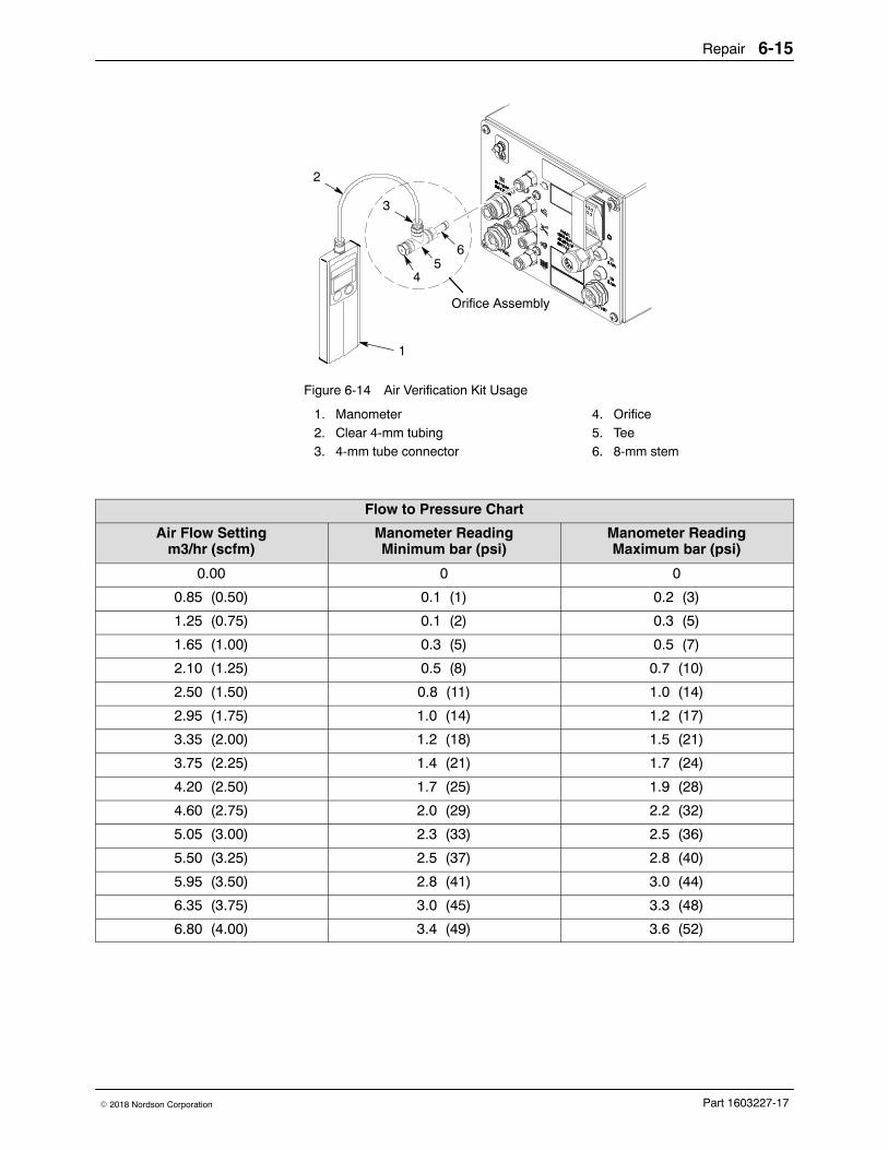
Repair 6-15
Part 1603227-17� 2018 Nordson Corporation
1
45
6
3
2
Orifice Assembly
Figure 6-14 Air Verification Kit Usage
1. Manometer2. Clear 4-mm tubing3. 4-mm tube connector
4. Orifice5. Tee6. 8-mm stem
Flow to Pressure Chart
Air Flow Settingm3/hr (scfm)
Manometer ReadingMinimum bar (psi)
Manometer ReadingMaximum bar (psi)
0.00 0 0
0.85 (0.50) 0.1 (1) 0.2 (3)
1.25 (0.75) 0.1 (2) 0.3 (5)
1.65 (1.00) 0.3 (5) 0.5 (7)
2.10 (1.25) 0.5 (8) 0.7 (10)
2.50 (1.50) 0.8 (11) 1.0 (14)
2.95 (1.75) 1.0 (14) 1.2 (17)
3.35 (2.00) 1.2 (18) 1.5 (21)
3.75 (2.25) 1.4 (21) 1.7 (24)
4.20 (2.50) 1.7 (25) 1.9 (28)
4.60 (2.75) 2.0 (29) 2.2 (32)
5.05 (3.00) 2.3 (33) 2.5 (36)
5.50 (3.25) 2.5 (37) 2.8 (40)
5.95 (3.50) 2.8 (41) 3.0 (44)
6.35 (3.75) 3.0 (45) 3.3 (48)
6.80 (4.00) 3.4 (49) 3.6 (52)
Repair6-16
Part 1603227-17 � 2018 Nordson Corporation
Solenoid Valve Replacement See Figure 6-15. To remove the solenoid valves (13), remove the twoscrews in the valve body and lift the valve off the manifold.
Make sure the O-rings furnished with the new valves are in place beforeinstalling the new valve on the manifold.
Proportional Valve Cleaning See Figure 6-15. A dirty air supply can cause the proportional valve (6) tomalfunction. Follow these instructions to disassemble and clean the valve.
1. Disconnect the coil (3) wiring from the circuit board (1). Remove the nut(2) and coil from the proportional valve (6).
2. Remove the two long screws (4) and two short screws (5) to remove theproportional valve from the manifold.
CAUTION: The valve parts are very small; be careful not to lose any. Donot mix the springs from one valve with those from another. The valves arecalibrated for different springs.
3. Remove the valve stem (8) from the valve body (11).
4. Remove the valve cartridge (10) and spring (9) from the stem.
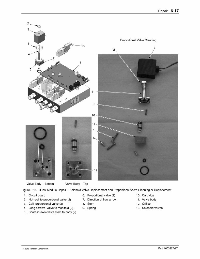
Repair 6-17
Part 1603227-17� 2018 Nordson Corporation
2
3
4
6
5
7
1
Valve Body − Bottom Valve Body − Top
32
8
9
10
11
4
5
12
13
Proportional Valve Cleaning
Figure 6-15 iFlow Module Repair − Solenoid Valve Replacement and Proportional Valve Cleaning or Replacement
1. Circuit board2. Nut−coil to proportional valve (2)3. Coil−proportional valve (2)4. Long screws−valve to manifold (2)5. Short screws−valve stem to body (2)
6. Proportional valve (2)7. Direction of flow arrow8. Stem9. Spring
10. Cartridge11. Valve body12. Orifice13. Solenoid valves
Repair6-18
Part 1603227-17 � 2018 Nordson Corporation
Proportional Valve Cleaning (contd)
5. Clean the cartridge seat and seals, and the orifice in the valve body.Use low-pressure compressed air. Do not use sharp metal tools toclean the cartridge or valve body.
6. Install the spring and then the cartridge in the stem, with the plastic seaton the end of the cartridge facing out.
7. Make sure the O-rings furnished with the valve are in place on thebottom of the valve body.
8. Secure the valve body to the manifold with the long screws, making surethe arrow on the side of the body points toward the outlet fittings.
9. Install the coil over the valve stem, with the coil wiring pointing towardthe circuit board. Secure the coil with the nut and connect the coil wiringto the circuit board.
Proportional Valve Replacement See Figure 6-15. If cleaning the proportional valve does not correct the flowproblem then replace the valve. Before installing a new valve, remove theprotective cover from the bottom of the valve body. Be careful to not losethe O-rings under the cover.
Vibrator Motor Replacement When replacing the vibrator motor, make sure you order the correct motorfor your voltage. Check the ID plate on the power unit. Replacementmotors include the power cable.
Refer to the Power Unit Wiring Diagram in the Troubleshooting section ofthis manual for internal VBF wiring.
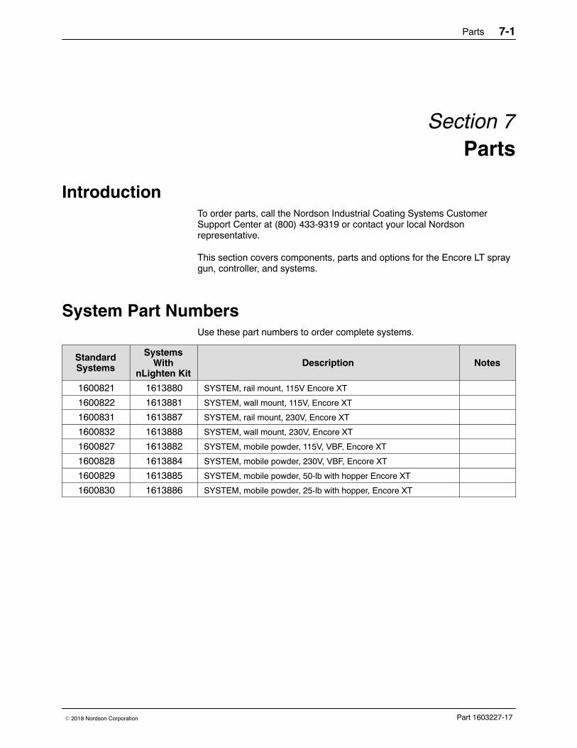
Parts 7-1
Part 1603227-17� 2018 Nordson Corporation
Section 7Parts
Introduction To order parts, call the Nordson Industrial Coating Systems CustomerSupport Center at (800) 433-9319 or contact your local Nordsonrepresentative.
This section covers components, parts and options for the Encore LT spraygun, controller, and systems.
System Part Numbers Use these part numbers to order complete systems.
StandardSystems
SystemsWith
nLighten KitDescription Notes
1600821 1613880 SYSTEM, rail mount, 115V Encore XT
1600822 1613881 SYSTEM, wall mount, 115V, Encore XT
1600831 1613887 SYSTEM, rail mount, 230V, Encore XT
1600832 1613888 SYSTEM, wall mount, 230V, Encore XT
1600827 1613882 SYSTEM, mobile powder, 115V, VBF, Encore XT
1600828 1613884 SYSTEM, mobile powder, 230V, VBF, Encore XT
1600829 1613885 SYSTEM, mobile powder, 50-lb with hopper Encore XT
1600830 1613886 SYSTEM, mobile powder, 25-lb with hopper, Encore XT
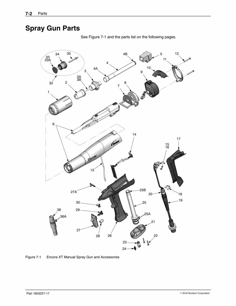
Parts7-2
Part 1603227-17 � 2018 Nordson Corporation
Spray Gun Parts See Figure 7-1 and the parts list on the following pages.
1
2
4
5
6
78
910
11
12
13
17
18
19
21
22
15
14
30 25
29
23
27
24
26
16
4A
4B
25B
25A
3433
33A
36
36A
27A
28
20
3
35
32
3A3B
Figure 7-1 Encore XT Manual Spray Gun and Accessories
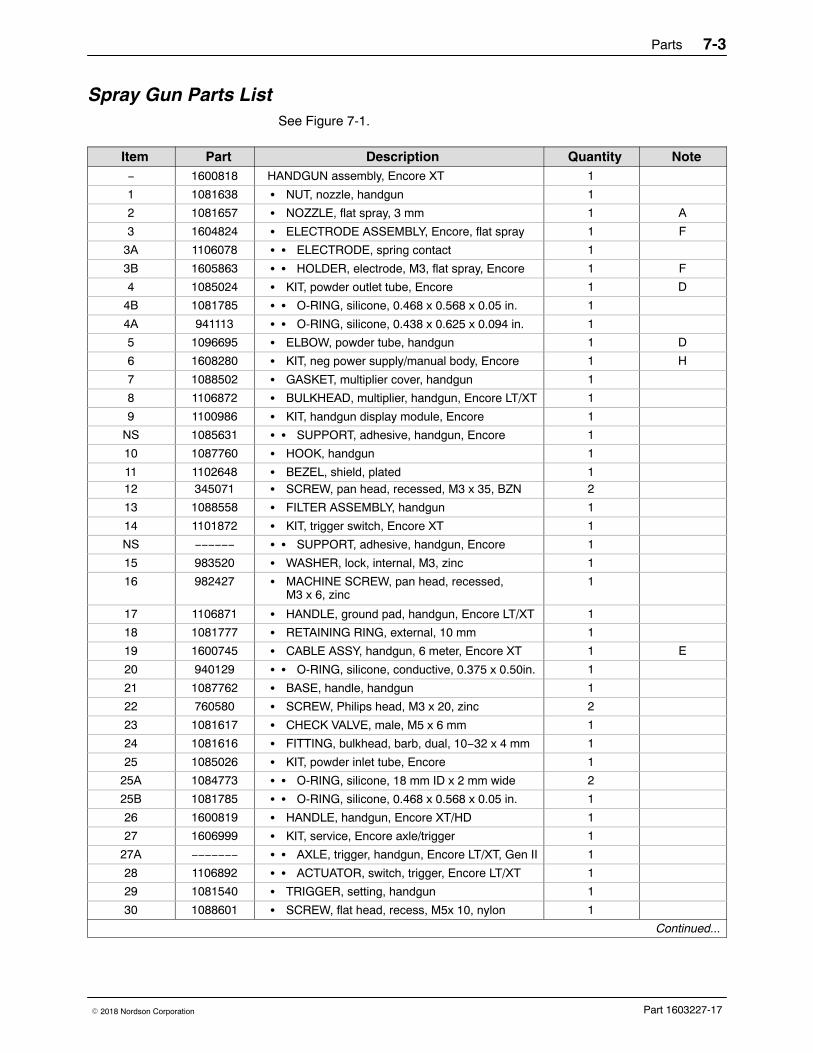
Parts 7-3
Part 1603227-17� 2018 Nordson Corporation
Spray Gun Parts List See Figure 7-1.
Item Part Description Quantity Note− 1600818 HANDGUN assembly, Encore XT 1
1 1081638 � NUT, nozzle, handgun 1
2 1081657 � NOZZLE, flat spray, 3 mm 1 A
3 1604824 � ELECTRODE ASSEMBLY, Encore, flat spray 1 F
3A 1106078 � � ELECTRODE, spring contact 1
3B 1605863 � � HOLDER, electrode, M3, flat spray, Encore 1 F
4 1085024 � KIT, powder outlet tube, Encore 1 D
4B 1081785 � � O-RING, silicone, 0.468 x 0.568 x 0.05 in. 1
4A 941113 � � O-RING, silicone, 0.438 x 0.625 x 0.094 in. 1
5 1096695 � ELBOW, powder tube, handgun 1 D
6 1608280 � KIT, neg power supply/manual body, Encore 1 H
7 1088502 � GASKET, multiplier cover, handgun 1
8 1106872 � BULKHEAD, multiplier, handgun, Encore LT/XT 1
9 1100986 � KIT, handgun display module, Encore 1
NS 1085631 � � SUPPORT, adhesive, handgun, Encore 1
10 1087760 � HOOK, handgun 1
11 1102648 � BEZEL, shield, plated 112 345071 � SCREW, pan head, recessed, M3 x 35, BZN 2
13 1088558 � FILTER ASSEMBLY, handgun 1
14 1101872 � KIT, trigger switch, Encore XT 1
NS −−−−−− � � SUPPORT, adhesive, handgun, Encore 1
15 983520 � WASHER, lock, internal, M3, zinc 1
16 982427 � MACHINE SCREW, pan head, recessed,M3 x 6, zinc
1
17 1106871 � HANDLE, ground pad, handgun, Encore LT/XT 1
18 1081777 � RETAINING RING, external, 10 mm 1
19 1600745 � CABLE ASSY, handgun, 6 meter, Encore XT 1 E
20 940129 � � O-RING, silicone, conductive, 0.375 x 0.50in. 1
21 1087762 � BASE, handle, handgun 1
22 760580 � SCREW, Philips head, M3 x 20, zinc 2
23 1081617 � CHECK VALVE, male, M5 x 6 mm 1
24 1081616 � FITTING, bulkhead, barb, dual, 10−32 x 4 mm 1
25 1085026 � KIT, powder inlet tube, Encore 1
25A 1084773 � � O-RING, silicone, 18 mm ID x 2 mm wide 2
25B 1081785 � � O-RING, silicone, 0.468 x 0.568 x 0.05 in. 1
26 1600819 � HANDLE, handgun, Encore XT/HD 1
27 1606999 � KIT, service, Encore axle/trigger 1
27A −−−−−−− � � AXLE, trigger, handgun, Encore LT/XT, Gen II 1
28 1106892 � � ACTUATOR, switch, trigger, Encore LT/XT 1
29 1081540 � TRIGGER, setting, handgun 1
30 1088601 � SCREW, flat head, recess, M5x 10, nylon 1
Continued...
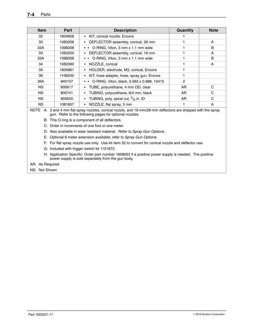
Parts7-4
Part 1603227-17 � 2018 Nordson Corporation
Item Part Description Quantity Note32 1604828 � KIT, conical nozzle, Encore 1
33 1083206 � DEFLECTOR assembly, conical, 26 mm 1 A
33A 1098306 � � O-RING, Viton, 3 mm x 1.1 mm wide 1 B33 1083205 � DEFLECTOR assembly, conical, 19 mm 1 A
33A 1098306 � � O-RING, Viton, 3 mm x 1.1 mm wide 1 B
34 1082060 � NOZZLE, conical 1 A
35 1605861 � HOLDER, electrode, M3, conical, Encore 1
36 1106200 � KIT, hose adapter, hose, spray gun, Encore 1
36A 940157 � � O-RING, Viton, black, 0.563 x 0.688, 10415 2
NS 900617 � TUBE, polyurethane, 4 mm OD, clear AR C
NS 900741 � TUBING, polyurethane, 6/4 mm, black AR C
NS 900620 � TUBING, poly, spiral cut, 3/8 in. ID AR C
NS 1081657 � NOZZLE, flat spray, 3 mm 1 A
NOTE A: 3 and 4 mm flat spray nozzles, conical nozzle, and 19-mm/26-mm deflectors are shipped with the spraygun. Refer to the following pages for optional nozzles.
B: This O-ring is a component of all deflectors.
C: Order in increments of one foot or one meter.
D: Also available in wear resistant material. Refer to Spray Gun Options.
E: Optional 6 meter extension available; refer to Spray Gun Options.
F: For flat spray nozzle use only. Use kit item 32 to convert for conical nozzle and deflector use.
G: Included with trigger switch kit 1101872.
H: Application Specific: Order part number 1609053 if a positive power supply is needed. The positivepower supply is sold separately from the gun body.
AR: As Required
NS: Not Shown
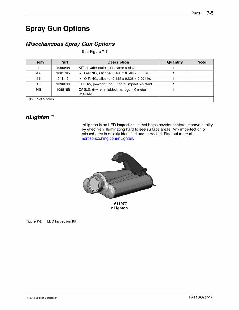
Parts 7-5
Part 1603227-17� 2018 Nordson Corporation
Spray Gun Options
Miscellaneous Spray Gun Options See Figure 7-1.
Item Part Description Quantity Note4 1096698 KIT, powder outlet tube, wear resistant 1
4A 1081785 � O-RING, silicone, 0.468 x 0.568 x 0.05 in. 1
4B 941113 � O-RING, silicone, 0.438 x 0.625 x 0.094 in. 1
18 1096696 ELBOW, powder tube, Encore, impact resistant 1
NS 1085168 CABLE, 6-wire, shielded, handgun, 6 meterextension
1
NS: Not Shown
nLighten� nLighten is an LED inspection kit that helps powder coaters improve qualityby effectively illuminating hard to see surface areas. Any imperfection ormissed area is quickly identified and corrected. Find out more at:nordsoncoating.com/nLighten.
1611977nLighten
Figure 7-2 LED Inspection Kit
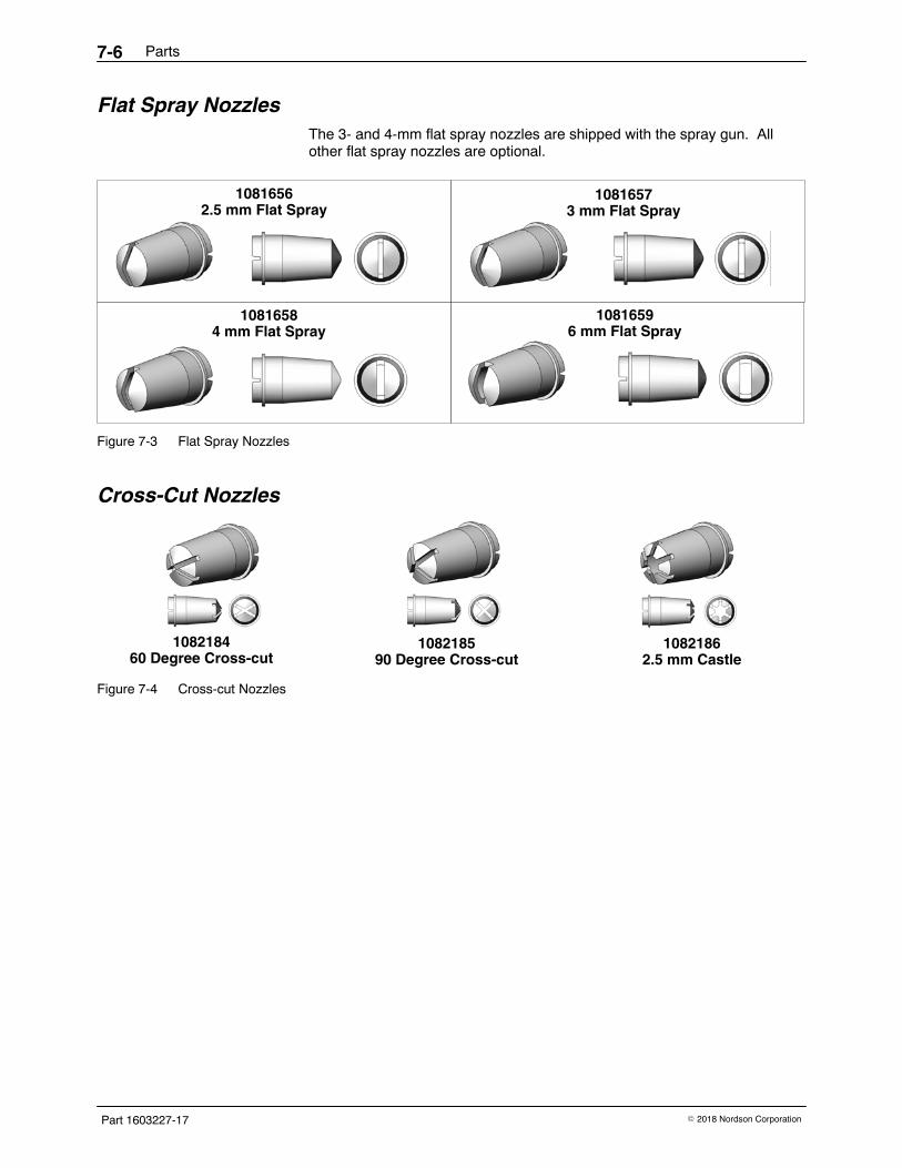
Parts7-6
Part 1603227-17 � 2018 Nordson Corporation
Flat Spray Nozzles The 3- and 4-mm flat spray nozzles are shipped with the spray gun. Allother flat spray nozzles are optional.
10816562.5 mm Flat Spray
10816573 mm Flat Spray
10816584 mm Flat Spray
10816596 mm Flat Spray
Figure 7-3 Flat Spray Nozzles
Cross-Cut Nozzles
108218460 Degree Cross-cut
108218590 Degree Cross-cut
10821862.5 mm Castle
Figure 7-4 Cross-cut Nozzles
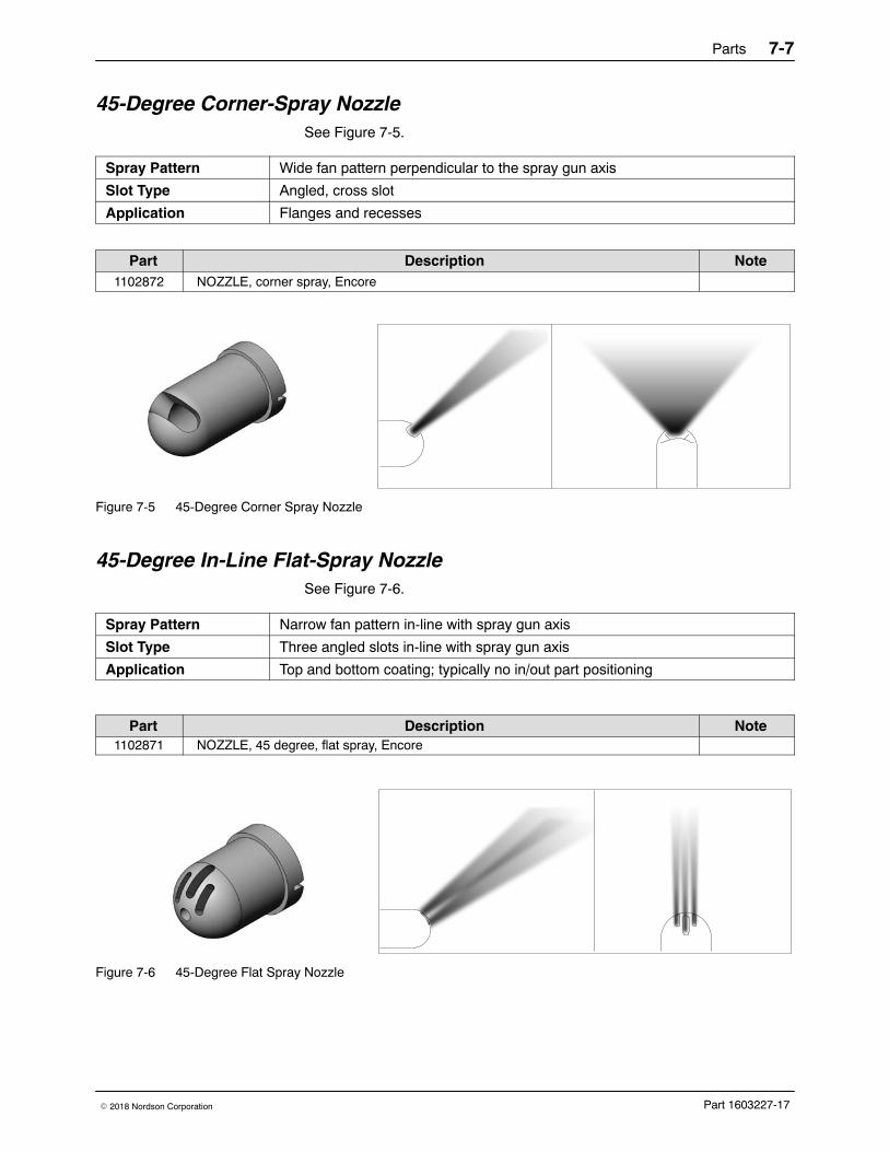
Parts 7-7
Part 1603227-17� 2018 Nordson Corporation
45-Degree Corner-Spray NozzleSee Figure 7-5.
Spray Pattern Wide fan pattern perpendicular to the spray gun axis
Slot Type Angled, cross slot
Application Flanges and recesses
Part Description Note1102872 NOZZLE, corner spray, Encore
Figure 7-5 45-Degree Corner Spray Nozzle
45-Degree In-Line Flat-Spray Nozzle See Figure 7-6.
Spray Pattern Narrow fan pattern in-line with spray gun axis
Slot Type Three angled slots in-line with spray gun axis
Application Top and bottom coating; typically no in/out part positioning
Part Description Note1102871 NOZZLE, 45 degree, flat spray, Encore
Figure 7-6 45-Degree Flat Spray Nozzle
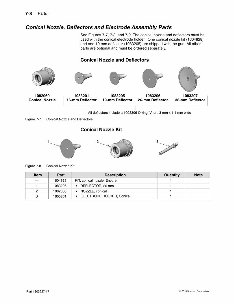
Parts7-8
Part 1603227-17 � 2018 Nordson Corporation
Conical Nozzle, Deflectors and Electrode Assembly PartsSee Figures 7-7, 7-8, and 7-9. The conical nozzle and deflectors must beused with the conical electrode holder. One conical nozzle kit (1604828)and one 19 mm deflector (1083205) are shipped with the gun. All otherparts are optional and must be ordered separately.
Conical Nozzle and Deflectors
1082060Conical Nozzle
108320116-mm Deflector
108320519-mm Deflector
108320626-mm Deflector
108320738-mm Deflector
All deflectors include a 1098306 O-ring, Viton, 3 mm x 1.1 mm wide
Figure 7-7 Conical Nozzle and Deflectors
Conical Nozzle Kit
1 2 3
Figure 7-8 Conical Nozzle Kit
Item Part Description Quantity Note— 1604828 KIT, conical nozzle, Encore 1
1 1083206 � DEFLECTOR, 26 mm 1
2 1082060 � NOZZLE, conical 1
3 1605861 � ELECTRODE HOLDER, Conical 1
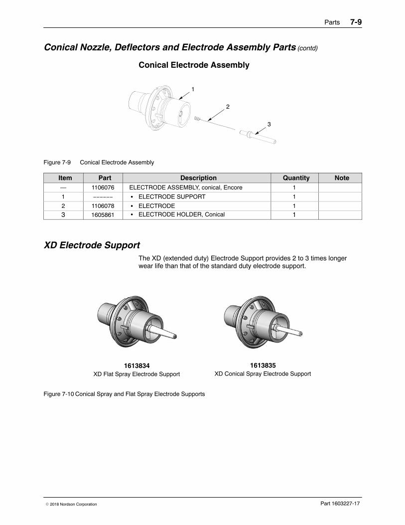
Parts 7-9
Part 1603227-17� 2018 Nordson Corporation
Conical Nozzle, Deflectors and Electrode Assembly Parts (contd)
Conical Electrode Assembly
1
2
3
Figure 7-9 Conical Electrode Assembly
Item Part Description Quantity Note— 1106076 ELECTRODE ASSEMBLY, conical, Encore 1
1 −−−−−− � ELECTRODE SUPPORT 1
2 1106078 � ELECTRODE 1
3 1605861 � ELECTRODE HOLDER, Conical 1
XD Electrode SupportThe XD (extended duty) Electrode Support provides 2 to 3 times longerwear life than that of the standard duty electrode support.
XD Conical Spray Electrode Support1613835
XD Flat Spray Electrode Support1613834
Figure 7-10 Conical Spray and Flat Spray Electrode Supports
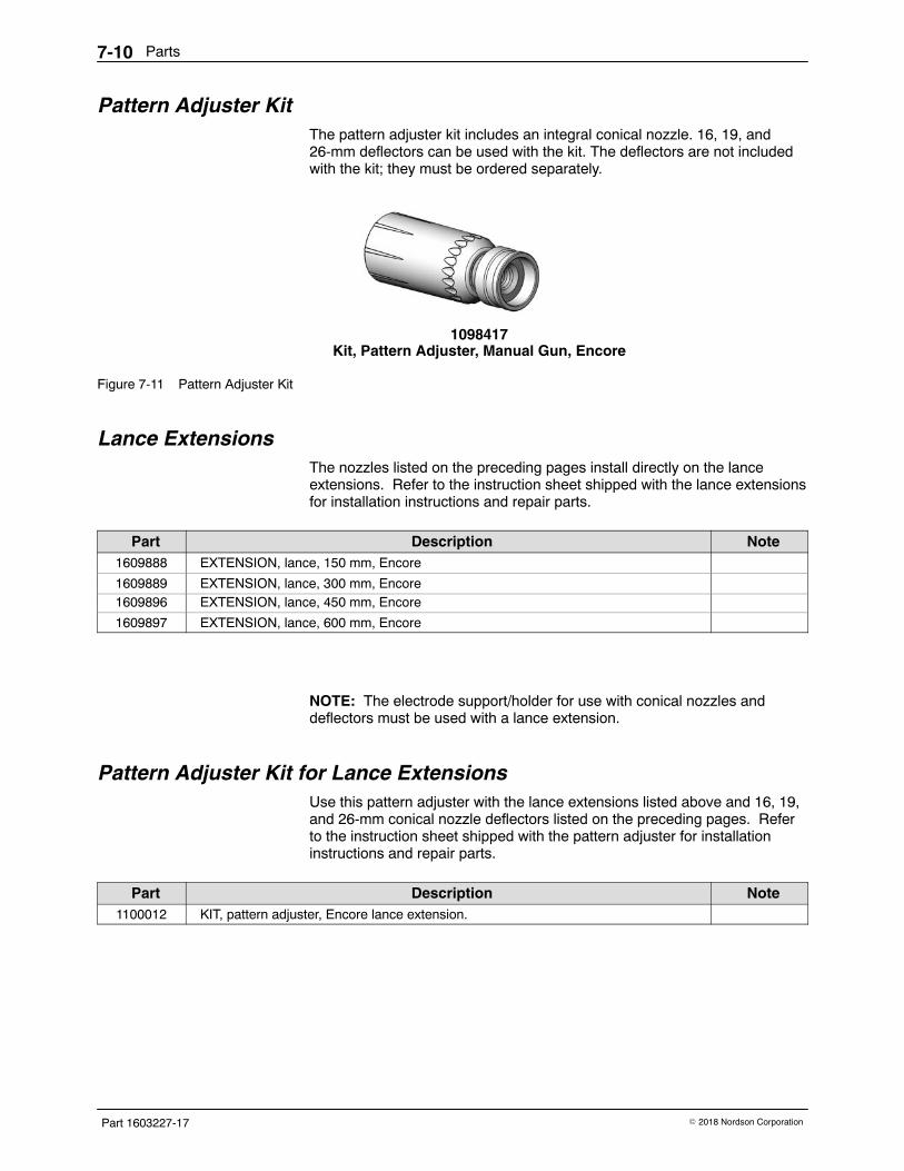
Parts7-10
Part 1603227-17 � 2018 Nordson Corporation
Pattern Adjuster Kit The pattern adjuster kit includes an integral conical nozzle. 16, 19, and26-mm deflectors can be used with the kit. The deflectors are not includedwith the kit; they must be ordered separately.
1098417Kit, Pattern Adjuster, Manual Gun, Encore
Figure 7-11 Pattern Adjuster Kit
Lance Extensions The nozzles listed on the preceding pages install directly on the lanceextensions. Refer to the instruction sheet shipped with the lance extensionsfor installation instructions and repair parts.
Part Description Note1609888 EXTENSION, lance, 150 mm, Encore
1609889 EXTENSION, lance, 300 mm, Encore1609896 EXTENSION, lance, 450 mm, Encore
1609897 EXTENSION, lance, 600 mm, Encore
NOTE: The electrode support/holder for use with conical nozzles anddeflectors must be used with a lance extension.
Pattern Adjuster Kit for Lance Extensions Use this pattern adjuster with the lance extensions listed above and 16, 19,and 26-mm conical nozzle deflectors listed on the preceding pages. Referto the instruction sheet shipped with the pattern adjuster for installationinstructions and repair parts.
Part Description Note1100012 KIT, pattern adjuster, Encore lance extension.
Parts 7-11
Part 1603227-17� 2018 Nordson Corporation
Ion Collector Kit This kit installs on the standard length gun. Refer to the instruction sheetshipped with the spray gun for installation instructions and repair parts.
Item Part Description Quantity Note— 1603854 KIT, ion collector assembly, manual, Encore (std
length gun)1
Ion Collector Components for Lance Extensions To use the ion collector kit listed above with 150-mm or 300-mm LanceExtensions, order one of the rods and the bracket listed below. Refer to theinstruction sheet shipped with the kit for installation instructions.
Item Part Description Quantity Note— 189483 ROD, ion collector, 15 in. 1 A
— 189484 ROD, ion collector, 21 in. 1 B
— 1603939 BRACKET, lance extension, ion collector, Encore 1 A, B
NOTE A: Use for 150-mm lance extension.
B: Use for 300-mm lance extension.
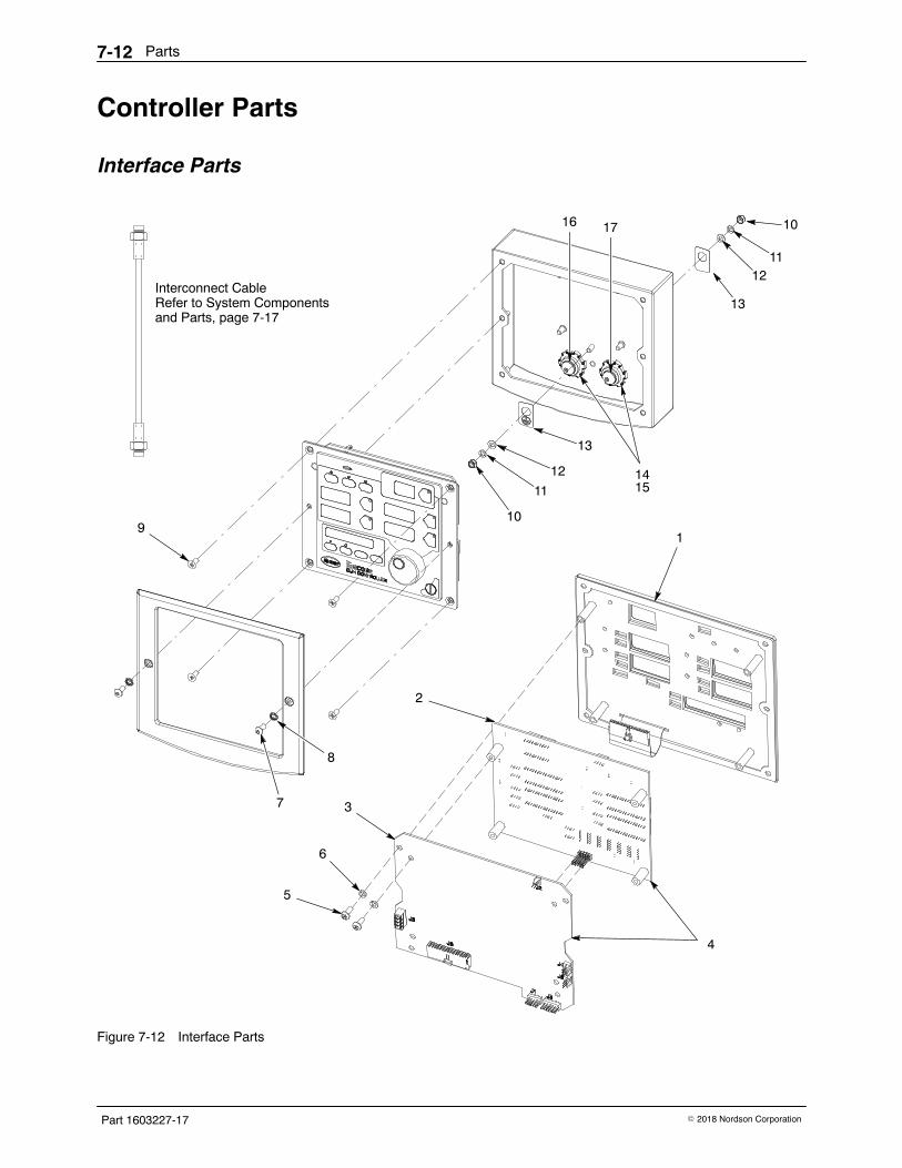
Parts7-12
Part 1603227-17 � 2018 Nordson Corporation
Controller Parts
Interface Parts
1
2
3
4
9
7
8
10
11
12
13
5
6
13
1211
10
1415
Interconnect CableRefer to System Componentsand Parts, page 7-17
16 17
Figure 7-12 Interface Parts
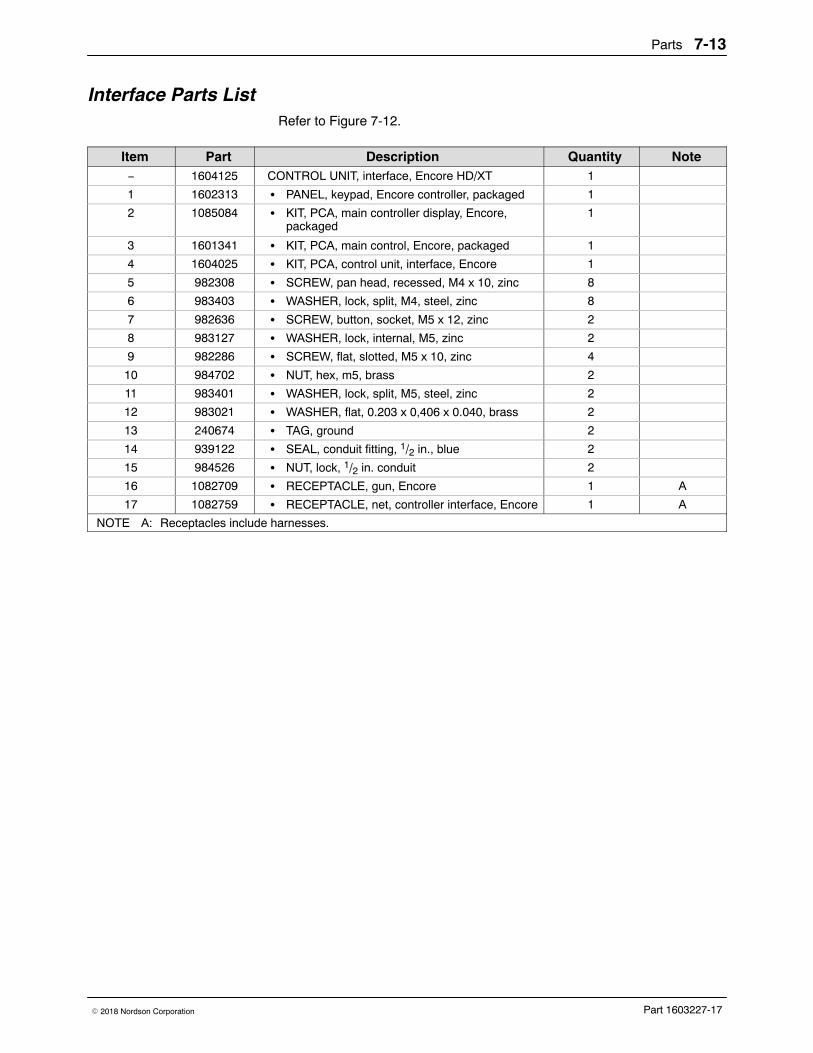
Parts 7-13
Part 1603227-17� 2018 Nordson Corporation
Interface Parts List Refer to Figure 7-12.
Item Part Description Quantity Note− 1604125 CONTROL UNIT, interface, Encore HD/XT 1
1 1602313 � PANEL, keypad, Encore controller, packaged 1
2 1085084 � KIT, PCA, main controller display, Encore,packaged
1
3 1601341 � KIT, PCA, main control, Encore, packaged 1
4 1604025 � KIT, PCA, control unit, interface, Encore 1
5 982308 � SCREW, pan head, recessed, M4 x 10, zinc 8
6 983403 � WASHER, lock, split, M4, steel, zinc 8
7 982636 � SCREW, button, socket, M5 x 12, zinc 2
8 983127 � WASHER, lock, internal, M5, zinc 2
9 982286 � SCREW, flat, slotted, M5 x 10, zinc 4
10 984702 � NUT, hex, m5, brass 2
11 983401 � WASHER, lock, split, M5, steel, zinc 2
12 983021 � WASHER, flat, 0.203 x 0,406 x 0.040, brass 2
13 240674 � TAG, ground 2
14 939122 � SEAL, conduit fitting, 1/2 in., blue 2
15 984526 � NUT, lock, 1/2 in. conduit 2
16 1082709 � RECEPTACLE, gun, Encore 1 A
17 1082759 � RECEPTACLE, net, controller interface, Encore 1 A
NOTE A: Receptacles include harnesses.
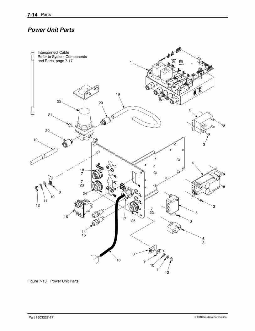
Parts7-14
Part 1603227-17 � 2018 Nordson Corporation
Power Unit Parts
1
22
21
20
19
1211
108
16
14
2
3
4
5
6
8
910
1112
20
19
13
17
7
18
7
15
3
3
3
7
23
23
Interconnect CableRefer to System Componentsand Parts, page 7-17
24
25
Figure 7-13 Power Unit Parts
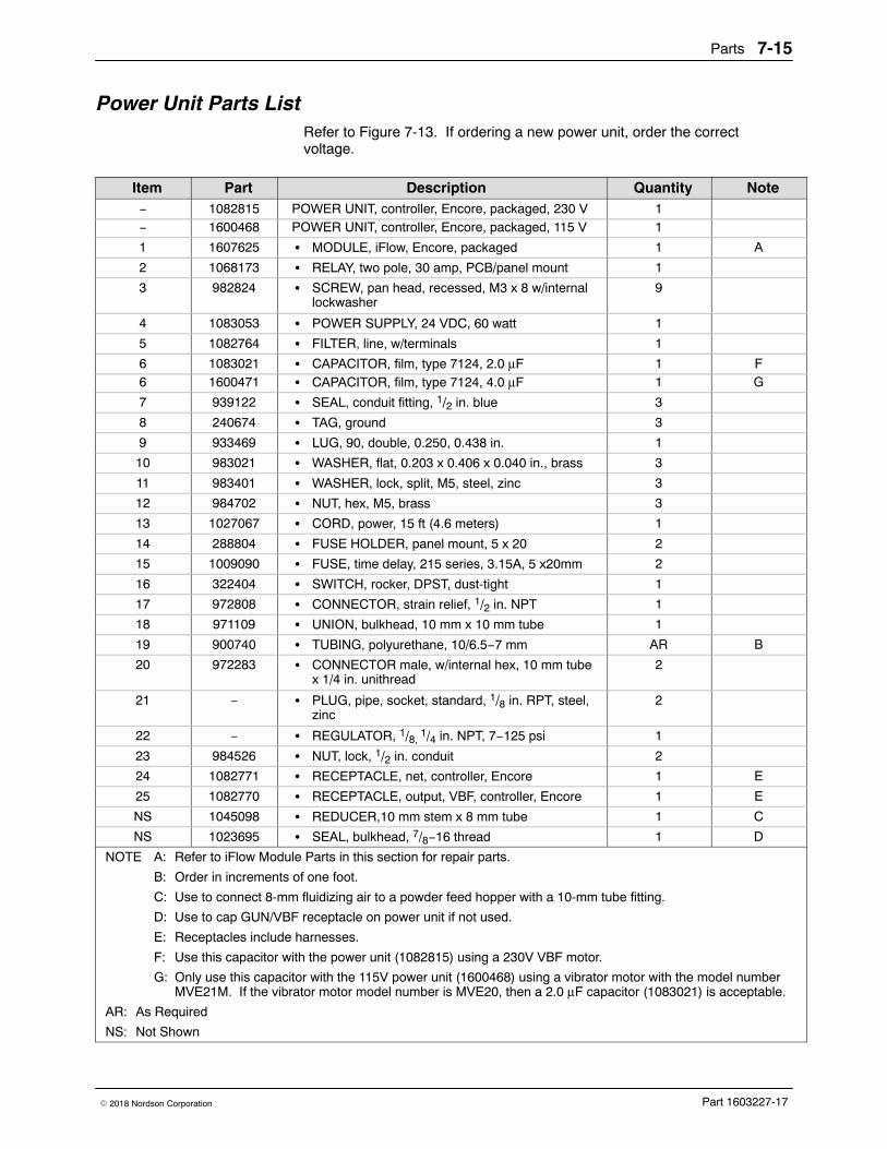
Parts 7-15
Part 1603227-17� 2018 Nordson Corporation
Power Unit Parts List Refer to Figure 7-13. If ordering a new power unit, order the correctvoltage.
Item Part Description Quantity Note− 1082815 POWER UNIT, controller, Encore, packaged, 230 V 1− 1600468 POWER UNIT, controller, Encore, packaged, 115 V 1
1 1607625 � MODULE, iFlow, Encore, packaged 1 A
2 1068173 � RELAY, two pole, 30 amp, PCB/panel mount 1
3 982824 � SCREW, pan head, recessed, M3 x 8 w/internallockwasher
9
4 1083053 � POWER SUPPLY, 24 VDC, 60 watt 1
5 1082764 � FILTER, line, w/terminals 1
6 1083021 � CAPACITOR, film, type 7124, 2.0 μF 1 F6 1600471 � CAPACITOR, film, type 7124, 4.0 μF 1 G
7 939122 � SEAL, conduit fitting, 1/2 in. blue 3
8 240674 � TAG, ground 3
9 933469 � LUG, 90, double, 0.250, 0.438 in. 1
10 983021 � WASHER, flat, 0.203 x 0.406 x 0.040 in., brass 3
11 983401 � WASHER, lock, split, M5, steel, zinc 3
12 984702 � NUT, hex, M5, brass 3
13 1027067 � CORD, power, 15 ft (4.6 meters) 1
14 288804 � FUSE HOLDER, panel mount, 5 x 20 2
15 1009090 � FUSE, time delay, 215 series, 3.15A, 5 x20mm 2
16 322404 � SWITCH, rocker, DPST, dust-tight 1
17 972808 � CONNECTOR, strain relief, 1/2 in. NPT 1
18 971109 � UNION, bulkhead, 10 mm x 10 mm tube 1
19 900740 � TUBING, polyurethane, 10/6.5−7 mm AR B
20 972283 � CONNECTOR male, w/internal hex, 10 mm tubex 1/4 in. unithread
2
21 − � PLUG, pipe, socket, standard, 1/8 in. RPT, steel,zinc
2
22 − � REGULATOR, 1/8, 1/4 in. NPT, 7−125 psi 1
23 984526 � NUT, lock, 1/2 in. conduit 2
24 1082771 � RECEPTACLE, net, controller, Encore 1 E
25 1082770 � RECEPTACLE, output, VBF, controller, Encore 1 E
NS 1045098 � REDUCER,10 mm stem x 8 mm tube 1 C
NS 1023695 � SEAL, bulkhead, 7/8−16 thread 1 D
NOTE A: Refer to iFlow Module Parts in this section for repair parts.
B: Order in increments of one foot.
C: Use to connect 8-mm fluidizing air to a powder feed hopper with a 10-mm tube fitting.
D: Use to cap GUN/VBF receptacle on power unit if not used.
E: Receptacles include harnesses.
F: Use this capacitor with the power unit (1082815) using a 230V VBF motor.
G: Only use this capacitor with the 115V power unit (1600468) using a vibrator motor with the model numberMVE21M. If the vibrator motor model number is MVE20, then a 2.0 μF capacitor (1083021) is acceptable.
AR: As Required
NS: Not Shown
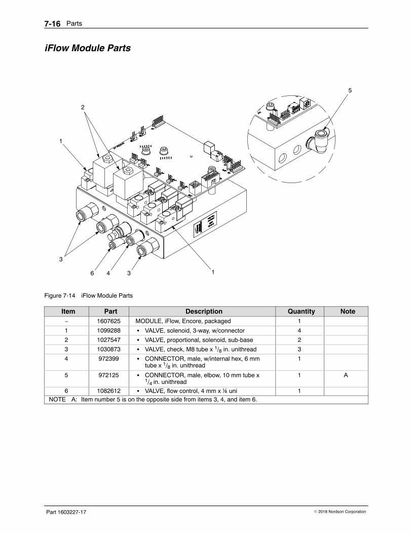
Parts7-16
Part 1603227-17 � 2018 Nordson Corporation
iFlow Module Parts
1
2
3
34
5
16
Figure 7-14 iFlow Module Parts
Item Part Description Quantity Note− 1607625 MODULE, iFlow, Encore, packaged 1
1 1099288 � VALVE, solenoid, 3-way, w/connector 4
2 1027547 � VALVE, proportional, solenoid, sub-base 2
3 1030873 � VALVE, check, M8 tube x 1/8 in. unithread 3
4 972399 � CONNECTOR, male, w/internal hex, 6 mmtube x 1/8 in. unithread
1
5 972125 � CONNECTOR, male, elbow, 10 mm tube x1/4 in. unithread
1 A
6 1082612 � VALVE, flow control, 4 mm x ⅛ uni 1NOTE A: Item number 5 is on the opposite side from items 3, 4, and item 6.
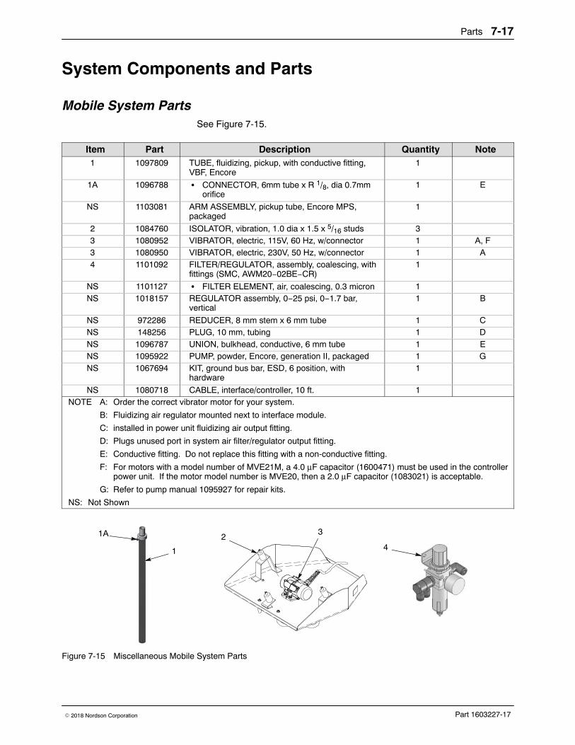
Parts 7-17
Part 1603227-17� 2018 Nordson Corporation
System Components and Parts
Mobile System Parts See Figure 7-15.
Item Part Description Quantity Note1 1097809 TUBE, fluidizing, pickup, with conductive fitting,
VBF, Encore1
1A 1096788 � CONNECTOR, 6mm tube x R 1/8, dia 0.7mmorifice
1 E
NS 1103081 ARM ASSEMBLY, pickup tube, Encore MPS,packaged
1
2 1084760 ISOLATOR, vibration, 1.0 dia x 1.5 x 5/16 studs 33 1080952 VIBRATOR, electric, 115V, 60 Hz, w/connector 1 A, F3 1080950 VIBRATOR, electric, 230V, 50 Hz, w/connector 1 A4 1101092 FILTER/REGULATOR, assembly, coalescing, with
fittings (SMC, AWM20−02BE−CR)1
NS 1101127 � FILTER ELEMENT, air, coalescing, 0.3 micron 1NS 1018157 REGULATOR assembly, 0−25 psi, 0−1.7 bar,
vertical1 B
NS 972286 REDUCER, 8 mm stem x 6 mm tube 1 CNS 148256 PLUG, 10 mm, tubing 1 DNS 1096787 UNION, bulkhead, conductive, 6 mm tube 1 ENS 1095922 PUMP, powder, Encore, generation II, packaged 1 GNS 1067694 KIT, ground bus bar, ESD, 6 position, with
hardware1
NS 1080718 CABLE, interface/controller, 10 ft. 1NOTE A: Order the correct vibrator motor for your system.
B: Fluidizing air regulator mounted next to interface module.
C: installed in power unit fluidizing air output fitting.
D: Plugs unused port in system air filter/regulator output fitting.
E: Conductive fitting. Do not replace this fitting with a non-conductive fitting.
F: For motors with a model number of MVE21M, a 4.0 μF capacitor (1600471) must be used in the controllerpower unit. If the motor model number is MVE20, then a 2.0 μF capacitor (1083021) is acceptable.
G: Refer to pump manual 1095927 for repair kits.
NS: Not Shown
1
21A
4
3
Figure 7-15 Miscellaneous Mobile System Parts
Parts7-18
Part 1603227-17 � 2018 Nordson Corporation
Wall/Rail Mount System Parts
Part Description Quantity Note1082482 KIT, rail mount, Encore LT 1
1600566 KIT, filter, Encore LT 1
1600608 � FILTER, mist separator, 0.3 micron, 1/2 in. NPT 1
1600609 � � FILTER ELEMENT, separator, 0.3 micron 1
971103 � CONNECTOR, male, 10 mm tube x 1/2 unithread 2
1600607 � CONNECTOR Y branch, 10 mm tube x 1/2 in. unithread 1
−−−−−− � BRACKET, assembly, mounting, modular air filter 1
972286 REDUCER, 8 mm stem x 6 mm tube 1 A
1095922 PUMP, powder, Encore, generation II, packaged 1 B
1067694 KIT, ground bus bar, ESD, 6 position, with hardware 1
1080718 CABLE, interface/controller, 10 ft. 1
NOTE A: Installed in power unit fluidizing air output fitting.
B: Refer to pump manual 1095927 for repair kits.
NS: Not Shown
Powder Hose and Air Tubing PartsPowder hose and air tubing must be ordered in increments of one foot.
Part Description Note768176 Powder hose, 11 mm antistatic A, E
768178 Powder hose, 12.7 mm (1/2 in.) antistatic A, E
900648 Powder hose, 11 mm blue D
900650 Powder hose, 12.7 mm (1/2 in.) blue D
900617 Air tubing, polyurethane, 4 mm, clear B
900742 Air tubing, polyurethane, 6 mm, blue B
1096789 Air tubing, antistatic, 6/4 mm, black (conductive air tubing) C
900741 Air tubing, polyurethane, 6 mm, black
900618 Air tubing, polyurethane, 8 mm, blue B
900619 Air tubing, polyurethane, 8 mm, black B
900740 Air tubing, polyurethane, 10 mm, blue B
900517 Tubing, poly, spiral cut, 0.62 in. ID
301841 Strap, Velcro, w/buckle, 25 x 3 cm
NOTE A: Twenty feet of 11-mm antistatic hose is provided with the systems. If you need to use a longer length, youmust switch to the 1/2 inch hose to prevent powder delivery issues.
B: Minimum order quantity is 50 ft.
C: This tubing is used on VBF systems to provide fluidizing air from the bulkhead union to the pickup tube. Itis conductive and grounds the pickup tube to the cart body. Do not replace with non-conductive tubing.
D: Minimum order quantity is 25 ft.
E: Minimum order quantity is 100 ft.
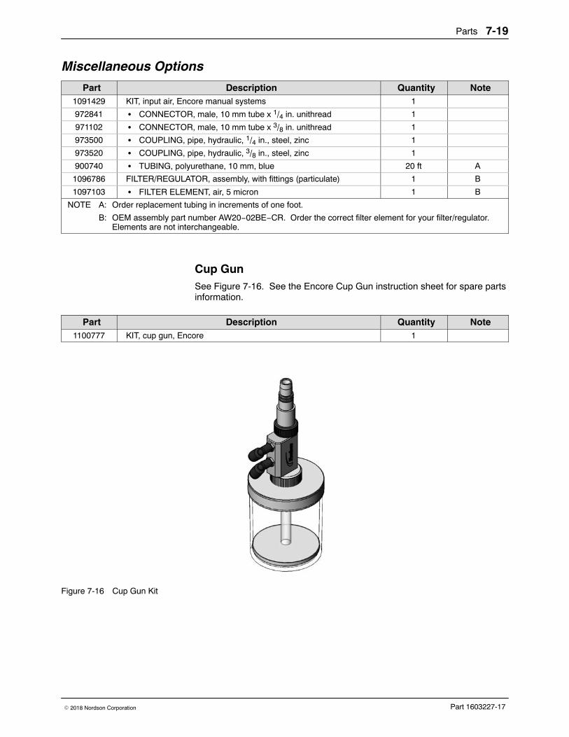
Parts 7-19
Part 1603227-17� 2018 Nordson Corporation
Miscellaneous Options
Part Description Quantity Note1091429 KIT, input air, Encore manual systems 1
972841 � CONNECTOR, male, 10 mm tube x 1/4 in. unithread 1
971102 � CONNECTOR, male, 10 mm tube x 3/8 in. unithread 1
973500 � COUPLING, pipe, hydraulic, 1/4 in., steel, zinc 1
973520 � COUPLING, pipe, hydraulic, 3/8 in., steel, zinc 1
900740 � TUBING, polyurethane, 10 mm, blue 20 ft A
1096786 FILTER/REGULATOR, assembly, with fittings (particulate) 1 B
1097103 � FILTER ELEMENT, air, 5 micron 1 B
NOTE A: Order replacement tubing in increments of one foot.
B: OEM assembly part number AW20−02BE−CR. Order the correct filter element for your filter/regulator.Elements are not interchangeable.
Cup Gun See Figure 7-16. See the Encore Cup Gun instruction sheet for spare partsinformation.
Part Description Quantity Note1100777 KIT, cup gun, Encore 1
Figure 7-16 Cup Gun Kit
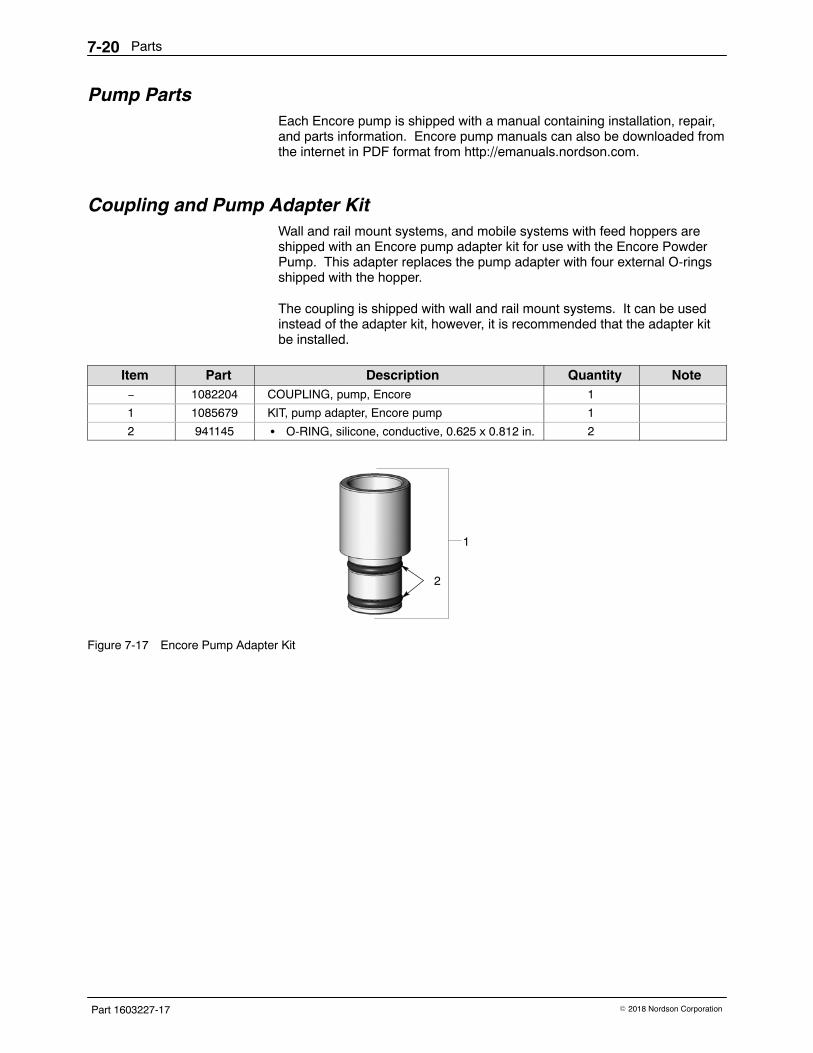
Parts7-20
Part 1603227-17 � 2018 Nordson Corporation
Pump Parts Each Encore pump is shipped with a manual containing installation, repair,and parts information. Encore pump manuals can also be downloaded fromthe internet in PDF format from http://emanuals.nordson.com.
Coupling and Pump Adapter Kit Wall and rail mount systems, and mobile systems with feed hoppers areshipped with an Encore pump adapter kit for use with the Encore PowderPump. This adapter replaces the pump adapter with four external O-ringsshipped with the hopper.
The coupling is shipped with wall and rail mount systems. It can be usedinstead of the adapter kit, however, it is recommended that the adapter kitbe installed.
Item Part Description Quantity Note− 1082204 COUPLING, pump, Encore 1
1 1085679 KIT, pump adapter, Encore pump 1
2 941145 � O-RING, silicone, conductive, 0.625 x 0.812 in. 2
2
1
Figure 7-17 Encore Pump Adapter Kit
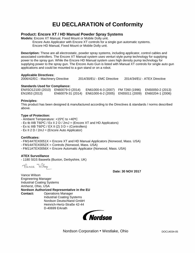
EU DECLARATION of Conformity Product: Encore XT / HD Manual Powder Spray Systems Models: Encore XT Manual, Fixed Mount or Mobile Dolly unit. Encore Auto Applicator with Encore XT controls for a single gun automatic systems. Encore HD Manual, Fixed Mount or Mobile Dolly unit. Description: These are all electrostatic, powder spray systems, including applicator, control cables and associated controllers. The Encore XT Manual system uses venturi style pump technology for supplying power to the spray gun. While the Encore HD Manual system uses high density pump technology for supplying power to the spray gun. The Encore Auto Gun is listed with Manual XT controls for single auto gun applications and could be mounted to a gun stand or on a robot. Applicable Directives: 2006/42/EC - Machinery Directive 2014/30/EU - EMC Directive 2014/34/EU - ATEX Directive Standards Used for Compliance: EN/ISO12100 (2010) EN60079-0 (2014) EN61000-6-3 (2007) FM 7260 (1996) EN50050-2 (2013) EN1953 (2013) EN60079-31 (2014) EN61000-6-2 (2005) EN55011 (2009) EN60204-1 (2006) Principles: This product has been designed & manufactured according to the Directives & standards / norms described above. Type of Protection: - Ambient Temperature: +15ºC to +40ºC - Ex tb IIIB T60ºC / Ex II 2 D / 2mJ = (Encore XT and HD Applicators) - Ex tc IIIB T60ºC / EX II (2) 3 D = (Controllers) - Ex II 2 D / 2mJ = (Encore Auto Applicator) Certificates: - FM14ATEX0051X = Encore XT and HD Manual Applicators (Norwood, Mass. USA) - FM14ATEX0052X = Controls (Norwood, Mass. USA) - FM11ATEX0056X = Encore Automatic Applicator (Norwood, Mass. USA) ATEX Surveillance - 1180 SGS Baseefa (Buxton, Derbyshire, UK)
Date: 30 NOV 2017 Vance Wilson Engineering Manager Industrial Coating Systems Amherst, Ohio, USA Nordson Authorized Representative in the EU Contact: Operations Manager Industrial Coating Systems Nordson Deutschland GmbH Heinrich-Hertz-Straße 42-44 D-40699 Erkrath
Nordson Corporation Westlake, Ohio DOC14034-05
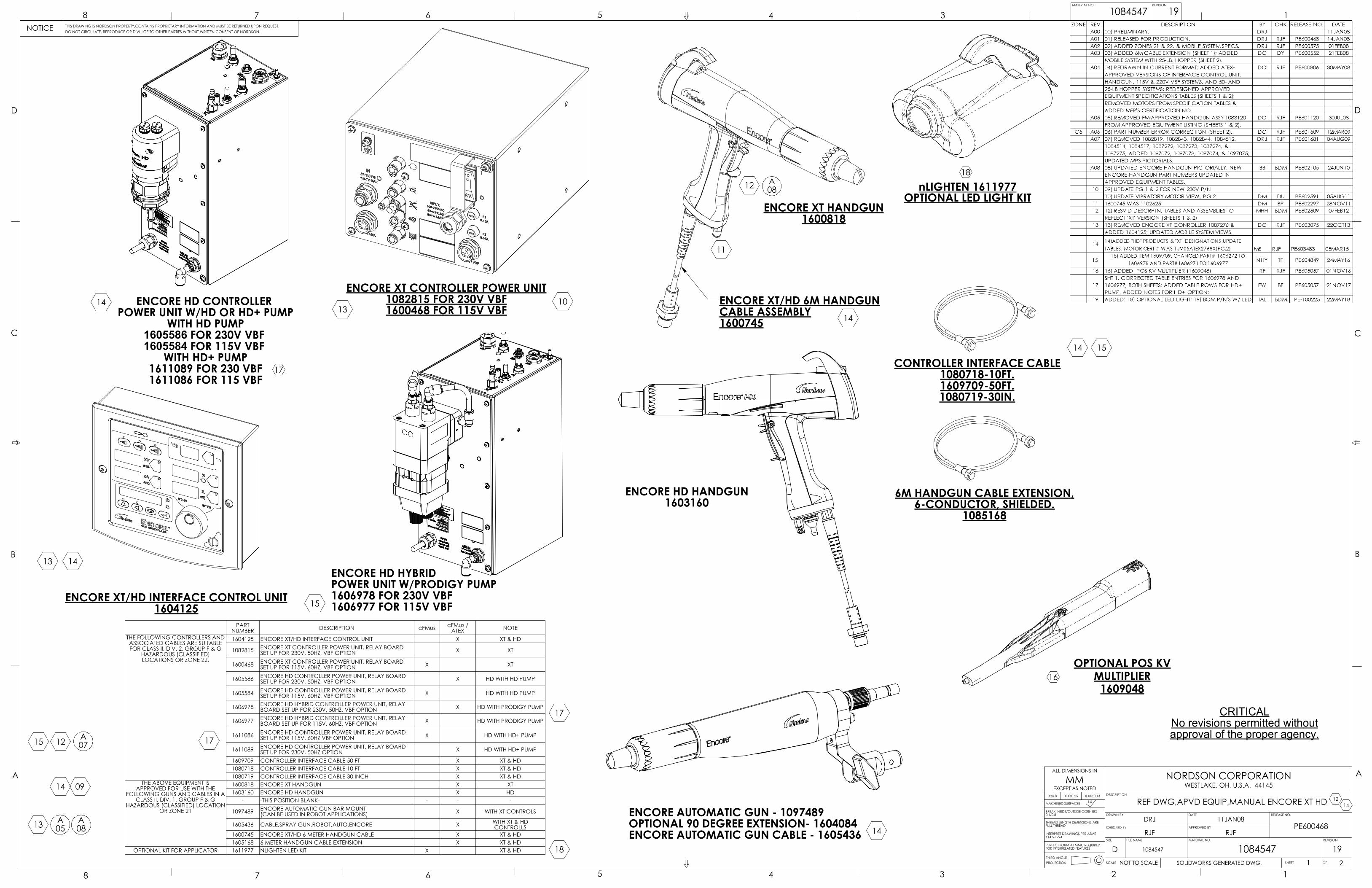
CRITICALNo revisions permitted withoutapproval of the proper agency.
CONTROLLER INTERFACE CABLE1080718-10FT.1609709-50FT.1080719-30IN.
6M HANDGUN CABLE EXTENSION,6-CONDUCTOR, SHIELDED.
1085168
ENCORE XT CONTROLLER POWER UNIT1082815 FOR 230V VBF1600468 FOR 115V VBF
10
14
14
ENCORE XT/HD 6M HANDGUNCABLE ASSEMBLY1600745
11
ENCORE XT HANDGUN1600818
A0812
ENCORE XT/HD INTERFACE CONTROL UNIT1604125
13 14
ENCORE HD CONTROLLER POWER UNIT W/HD OR HD+ PUMP
WITH HD PUMP1605586 FOR 230V VBF 1605584 FOR 115V VBF
WITH HD+ PUMP1611089 FOR 230 VBF1611086 FOR 115 VBF
14
ENCORE AUTOMATIC GUN - 1097489OPTIONAL 90 DEGREE EXTENSION- 1604084ENCORE AUTOMATIC GUN CABLE - 1605436 14
ENCORE HD HYBRIDPOWER UNIT W/PRODIGY PUMP1606978 FOR 230V VBF1606977 FOR 115V VBF
OPTIONAL POS KVMULTIPLIER
160904816
nLIGHTEN 1611977OPTIONAL LED LIGHT KIT
18
A05
A07
A08
09
12
12
13
13
ENCORE HD HANDGUN1603160
14
14
15
15
15
17
17
17
18
PARTNUMBER DESCRIPTION cFMus cFMus /
ATEX NOTETHE FOLLOWING CONTROLLERS AND ASSOCIATED CABLES ARE SUITABLE FOR CLASS II, DIV. 2, GROUP F & G
HAZARDOUS (CLASSIFIED) LOCATIONS OR ZONE 22.
1604125 ENCORE XT/HD INTERFACE CONTROL UNIT X XT & HD
1082815 ENCORE XT CONTROLLER POWER UNIT, RELAY BOARD SET UP FOR 230V, 50HZ, VBF OPTION X XT
1600468 ENCORE XT CONTROLLER POWER UNIT, RELAY BOARD SET UP FOR 115V, 60HZ, VBF OPTION X XT
1605586 ENCORE HD CONTROLLER POWER UNIT, RELAY BOARD SET UP FOR 230V, 50HZ, VBF OPTION X HD WITH HD PUMP
1605584 ENCORE HD CONTROLLER POWER UNIT, RELAY BOARD SET UP FOR 115V, 60HZ, VBF OPTION X HD WITH HD PUMP
1606978 ENCORE HD HYBRID CONTROLLER POWER UNIT, RELAY BOARD SET UP FOR 230V, 50HZ, VBF OPTION X HD WITH PRODIGY PUMP
1606977 ENCORE HD HYBRID CONTROLLER POWER UNIT, RELAY BOARD SET UP FOR 115V, 60HZ, VBF OPTION X HD WITH PRODIGY PUMP
1611086 ENCORE HD CONTROLLER POWER UNIT, RELAY BOARD SET UP FOR 115V, 60HZ VBF OPTION X HD WITH HD+ PUMP
1611089 ENCORE HD CONTROLLER POWER UNIT, RELAY BOARD SET UP FOR 230V, 50HZ OPTION X HD WITH HD+ PUMP
1609709 CONTROLLER INTERFACE CABLE 50 FT X XT & HD1080718 CONTROLLER INTERFACE CABLE 10 FT X XT & HD1080719 CONTROLLER INTERFACE CABLE 30 INCH X XT & HD
THE ABOVE EQUIPMENT IS APPROVED FOR USE WITH THE
FOLLOWING GUNS AND CABLES IN A CLASS II, DIV. 1, GROUP F & G
HAZARDOUS (CLASSIFIED) LOCATION OR ZONE 21
1600818 ENCORE XT HANDGUN X XT1603160 ENCORE HD HANDGUN X HD
- -THIS POSITION BLANK- - - -
1097489 ENCORE AUTOMATIC GUN BAR MOUNT(CAN BE USED IN ROBOT APPLICATIONS) X WITH XT CONTROLS
1605436 CABLE,SPRAY GUN,ROBOT,AUTO,ENCORE X WITH XT & HD CONTROLLS
1600745 ENCORE XT/HD 6 METER HANDGUN CABLE X XT & HD1605168 6 METER HANDGUN CABLE EXTENSION X XT & HD
OPTIONAL KIT FOR APPLICATOR 1611977 NLIGHTEN LED KIT X XT & HD
8
A
7 6 5
THIS DRAWING IS NORDSON PROPERTY,CONTAINS PROPRIETARY INFORMATION AND MUST BE RETURNED UPON REQUEST.DO NOT CIRCULATE, REPRODUCE OR DIVULGE TO OTHER PARTIES WITHOUT WRITTEN CONSENT OF NORDSON.
B
C
D
NOTICE8 7 6 5
4 3 2 1
A
4 3 1084547 1
B
C
D
FILE NAME MATERIAL NO. REVISION
SCALE
ALL DIMENSIONS IN
SOLIDWORKS GENERATED DWG.
NORDSON CORPORATIONWESTLAKE, OH, U.S.A. 44145
DRAWN BY
CHECKED BY
MMEXCEPT AS NOTED
THIRD ANGLEPROJECTION
X±0.8 X.X±0.25
MACHINED SURFACES 1.6
BREAK INSIDE/OUTSIDE CORNERS0.1/0.8
THREAD LENGTH DIMENSIONS AREFULL THREAD
INTERPRET DRAWINGS PER ASMEY14.5-1994
PERFECT FORM AT MMC REQUIREDFOR INTERRELATED FEATURES
DESCRIPTION
DATE
APPROVED BY
RELEASE NO.
SIZE
MATERIAL NO. REVISION
DRJ 11JAN08PE600468
D 1084547 1084547 19NOT TO SCALE 1 OF 2SHEET
19
X.XX±0.13
RJF RJF
REF DWG,APVD EQUIP,MANUAL ENCORE XT HD
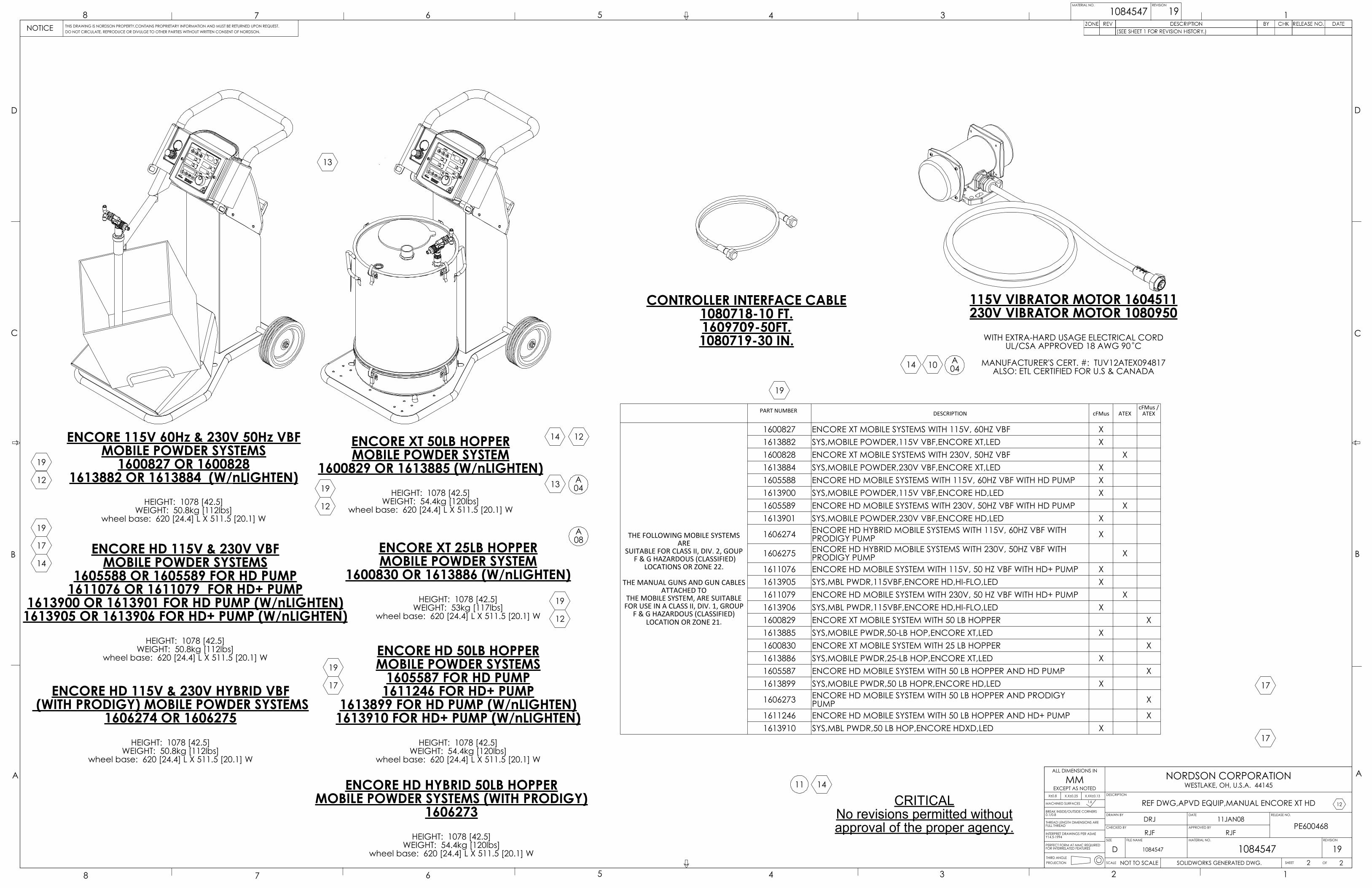
CRITICALNo revisions permitted withoutapproval of the proper agency.
CONTROLLER INTERFACE CABLE1080718-10 FT.1609709-50FT.1080719-30 IN.
115V VIBRATOR MOTOR 1604511230V VIBRATOR MOTOR 1080950
WITH EXTRA-HARD USAGE ELECTRICAL CORDUL/CSA APPROVED 18 AWG 90 C
MANUFACTURER'S CERT. #: TUV12ATEX094817ALSO: ETL CERTIFIED FOR U.S & CANADA
A04
ENCORE 115V 60Hz & 230V 50Hz VBFMOBILE POWDER SYSTEMS
1600827 OR 16008281613882 OR 1613884 (W/nLIGHTEN)
HEIGHT: 1078 [42.5]WEIGHT: 50.8kg [112lbs]
wheel base: 620 [24.4] L X 511.5 [20.1] W
ENCORE HD 115V & 230V VBFMOBILE POWDER SYSTEMS
1605588 OR 1605589 FOR HD PUMP1611076 OR 1611079 FOR HD+ PUMP
1613900 OR 1613901 FOR HD PUMP (W/nLIGHTEN)1613905 OR 1613906 FOR HD+ PUMP (W/nLIGHTEN)
HEIGHT: 1078 [42.5]WEIGHT: 50.8kg [112lbs]
wheel base: 620 [24.4] L X 511.5 [20.1] W
ENCORE HD 115V & 230V HYBRID VBF (WITH PRODIGY) MOBILE POWDER SYSTEMS
1606274 OR 1606275HEIGHT: 1078 [42.5]
WEIGHT: 50.8kg [112lbs]wheel base: 620 [24.4] L X 511.5 [20.1] W
ENCORE XT 50LB HOPPERMOBILE POWDER SYSTEM
1600829 OR 1613885 (W/nLIGHTEN)HEIGHT: 1078 [42.5]
WEIGHT: 54.4kg [120lbs]wheel base: 620 [24.4] L X 511.5 [20.1] W
ENCORE HD 50LB HOPPERMOBILE POWDER SYSTEMS
1605587 FOR HD PUMP1611246 FOR HD+ PUMP
1613899 FOR HD PUMP (W/nLIGHTEN)1613910 FOR HD+ PUMP (W/nLIGHTEN)
HEIGHT: 1078 [42.5]WEIGHT: 54.4kg [120lbs]
wheel base: 620 [24.4] L X 511.5 [20.1] W
ENCORE HD HYBRID 50LB HOPPERMOBILE POWDER SYSTEMS (WITH PRODIGY)
1606273HEIGHT: 1078 [42.5]
WEIGHT: 54.4kg [120lbs]wheel base: 620 [24.4] L X 511.5 [20.1] W
ENCORE XT 25LB HOPPERMOBILE POWDER SYSTEM
1600830 OR 1613886 (W/nLIGHTEN)HEIGHT: 1078 [42.5]
WEIGHT: 53kg [117lbs]wheel base: 620 [24.4] L X 511.5 [20.1] W
A08
A04
10
11
12
12
12
12
12
13
13
14
14
14
14
17 17
17
19
17
19
19
19
19
19
PART NUMBER DESCRIPTION cFMus ATEXcFMus /
ATEX
THE FOLLOWING MOBILE SYSTEMS ARE
SUITABLE FOR CLASS II, DIV. 2, GOUP F & G HAZARDOUS (CLASSIFIED)
LOCATIONS OR ZONE 22.
THE MANUAL GUNS AND GUN CABLES ATTACHED TO
THE MOBILE SYSTEM, ARE SUITABLEFOR USE IN A CLASS II, DIV. 1, GROUP
F & G HAZARDOUS (CLASSIFIED)LOCATION OR ZONE 21.
1600827 ENCORE XT MOBILE SYSTEMS WITH 115V, 60HZ VBF X1613882 SYS,MOBILE POWDER,115V VBF,ENCORE XT,LED X1600828 ENCORE XT MOBILE SYSTEMS WITH 230V, 50HZ VBF X1613884 SYS,MOBILE POWDER,230V VBF,ENCORE XT,LED X1605588 ENCORE HD MOBILE SYSTEMS WITH 115V, 60HZ VBF WITH HD PUMP X1613900 SYS,MOBILE POWDER,115V VBF,ENCORE HD,LED X1605589 ENCORE HD MOBILE SYSTEMS WITH 230V, 50HZ VBF WITH HD PUMP X1613901 SYS,MOBILE POWDER,230V VBF,ENCORE HD,LED X
1606274 ENCORE HD HYBRID MOBILE SYSTEMS WITH 115V, 60HZ VBF WITH PRODIGY PUMP X
1606275 ENCORE HD HYBRID MOBILE SYSTEMS WITH 230V, 50HZ VBF WITH PRODIGY PUMP X
1611076 ENCORE HD MOBILE SYSTEM WITH 115V, 50 HZ VBF WITH HD+ PUMP X1613905 SYS,MBL PWDR,115VBF,ENCORE HD,HI-FLO,LED X1611079 ENCORE HD MOBILE SYSTEM WITH 230V, 50 HZ VBF WITH HD+ PUMP X1613906 SYS,MBL PWDR,115VBF,ENCORE HD,HI-FLO,LED X1600829 ENCORE XT MOBILE SYSTEM WITH 50 LB HOPPER X1613885 SYS,MOBILE PWDR,50-LB HOP,ENCORE XT,LED X1600830 ENCORE XT MOBILE SYSTEM WITH 25 LB HOPPER X1613886 SYS,MOBILE PWDR,25-LB HOP,ENCORE XT,LED X1605587 ENCORE HD MOBILE SYSTEM WITH 50 LB HOPPER AND HD PUMP X1613899 SYS,MOBILE PWDR,50 LB HOPR,ENCORE HD,LED X
1606273 ENCORE HD MOBILE SYSTEM WITH 50 LB HOPPER AND PRODIGY PUMP X
1611246 ENCORE HD MOBILE SYSTEM WITH 50 LB HOPPER AND HD+ PUMP X1613910 SYS,MBL PWDR,50 LB HOP,ENCORE HDXD,LED X
8
A
7 6 5
THIS DRAWING IS NORDSON PROPERTY,CONTAINS PROPRIETARY INFORMATION AND MUST BE RETURNED UPON REQUEST.DO NOT CIRCULATE, REPRODUCE OR DIVULGE TO OTHER PARTIES WITHOUT WRITTEN CONSENT OF NORDSON.
B
C
D
NOTICE8 7 6 5
4 3 2 1
A
4 3 1084547 1
B
C
D
FILE NAME MATERIAL NO. REVISION
SCALE
ALL DIMENSIONS IN
REF DWG,APVD EQUIP,MANUAL ENCORE XT HD
SOLIDWORKS GENERATED DWG.
NORDSON CORPORATIONWESTLAKE, OH, U.S.A. 44145
DRAWN BY
CHECKED BY
MMEXCEPT AS NOTED
THIRD ANGLEPROJECTION
X±0.8 X.X±0.25
MACHINED SURFACES 1.6
BREAK INSIDE/OUTSIDE CORNERS0.1/0.8
THREAD LENGTH DIMENSIONS AREFULL THREAD
INTERPRET DRAWINGS PER ASMEY14.5-1994
PERFECT FORM AT MMC REQUIREDFOR INTERRELATED FEATURES
DESCRIPTION
DATE
APPROVED BY
RELEASE NO.
SIZE
MATERIAL NO. REVISION
DRJ 11JAN08PE600468
D 1084547 1084547 19NOT TO SCALE 2 OF 2SHEET
19
X.XX±0.13
RJF RJF