Embed Size (px)
Citation preview
6/18/2013
1
End Region Detailing of Pretensioned Concrete Bridge Girders
End Region Detailing of Pretensioned Concrete Bridge Girders
Trey Hamilton, PE, PhD, Univ. of FloridaBrandon E. Ross, PE, PhD, Clemson Univ.
Technical Coordinator: Sam Fallaha, PEFDOT Contract BDK75 977-05
2 of 57
Presentation Outline
Prestressing basics
Background on end region reinforcement
FIB54 Test Program – Service and Ultimate
FIB63 Test Program – Service
Findings
6/18/2013
2
3 of 57
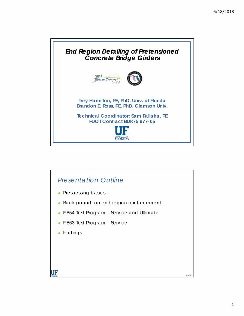
End Region
4 of 57
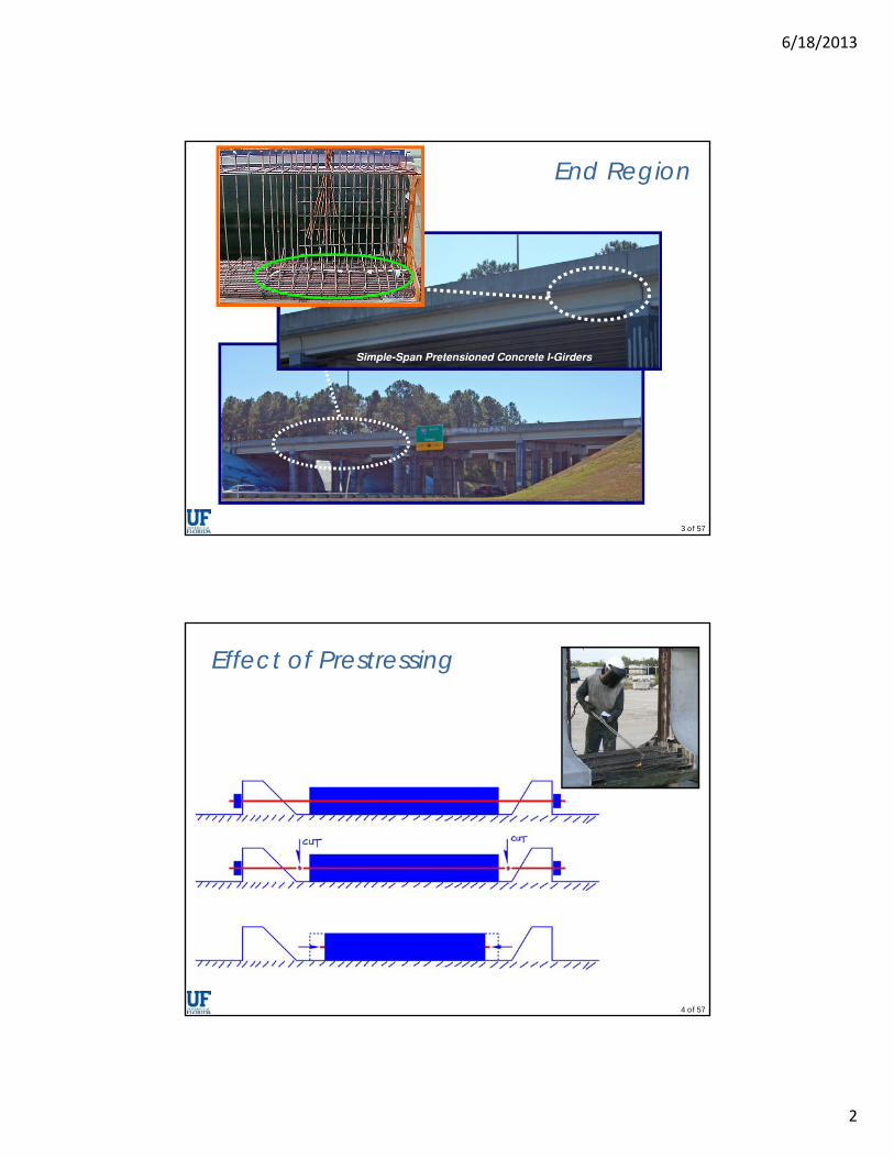
Effect of Prestressing
6/18/2013
3
5 of 57
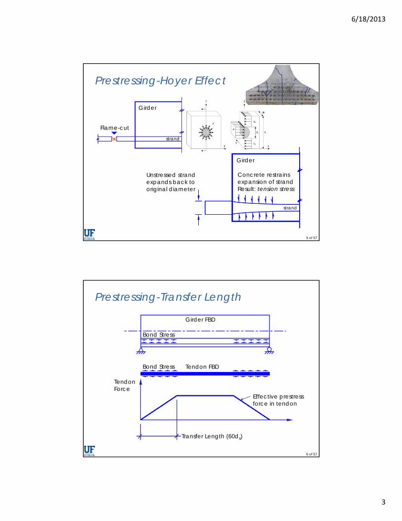
Prestressing-Hoyer Effect
Flame-cut
Unstressed strand expands back to original diameter
Girder
strand
Girder
strand
Concrete restrains expansion of strandResult: tension stress
6 of 57
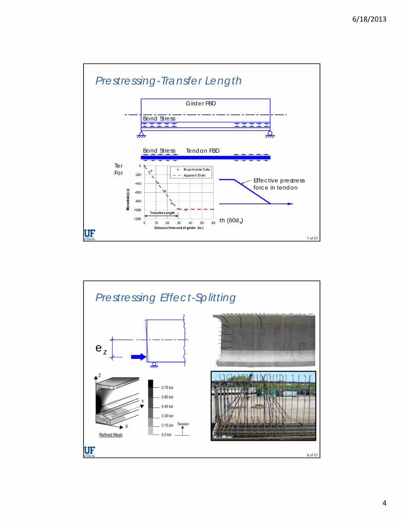
Prestressing-Transfer Length
Transfer Length (60ds)
TendonForce
Effective prestress force in tendon
Tendon FBD
Girder FBD
Bond Stress
Bond Stress
6/18/2013
4
7 of 57
Prestressing-Transfer Length
Transfer Length (60ds)
TendonForce
Effective prestress force in tendon
Tendon FBD
Girder FBD
Bond Stress
Bond Stress
8 of 57
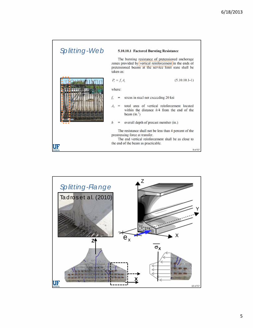
Prestressing Effect-Splitting
ez
6/18/2013
5
9 of 57
Splitting-Web
10 of 57
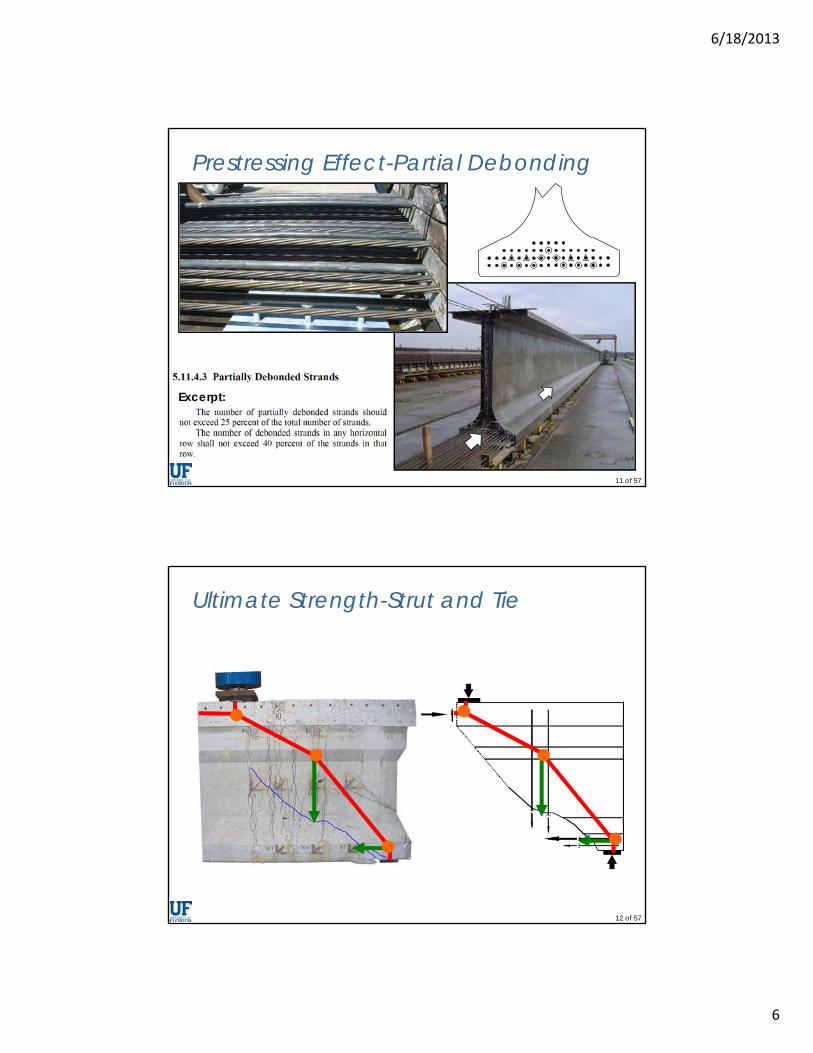
Splitting-Flange
Z
X
Tadros et al. (2010)
exX
6/18/2013
6
11 of 57
Prestressing Effect-Partial Debonding
Excerpt:
12 of 57
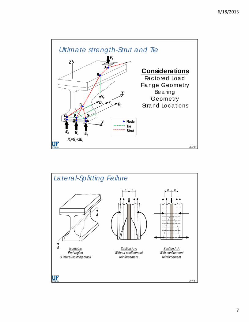
Ultimate Strength-Strut and Tie
6/18/2013
7
13 of 57
Ultimate strength-Strut and Tie
ConsiderationsFactored Load
Flange GeometryBearing
GeometryStrand Locations
14 of 57
Lateral-Splitting Failure
6/18/2013
8
15 of 57
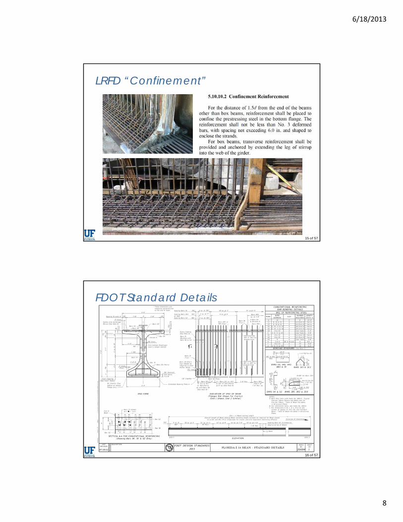
LRFD “Confinement”
16 of 57
FDOT Standard Details
6/18/2013
9
17 of 57
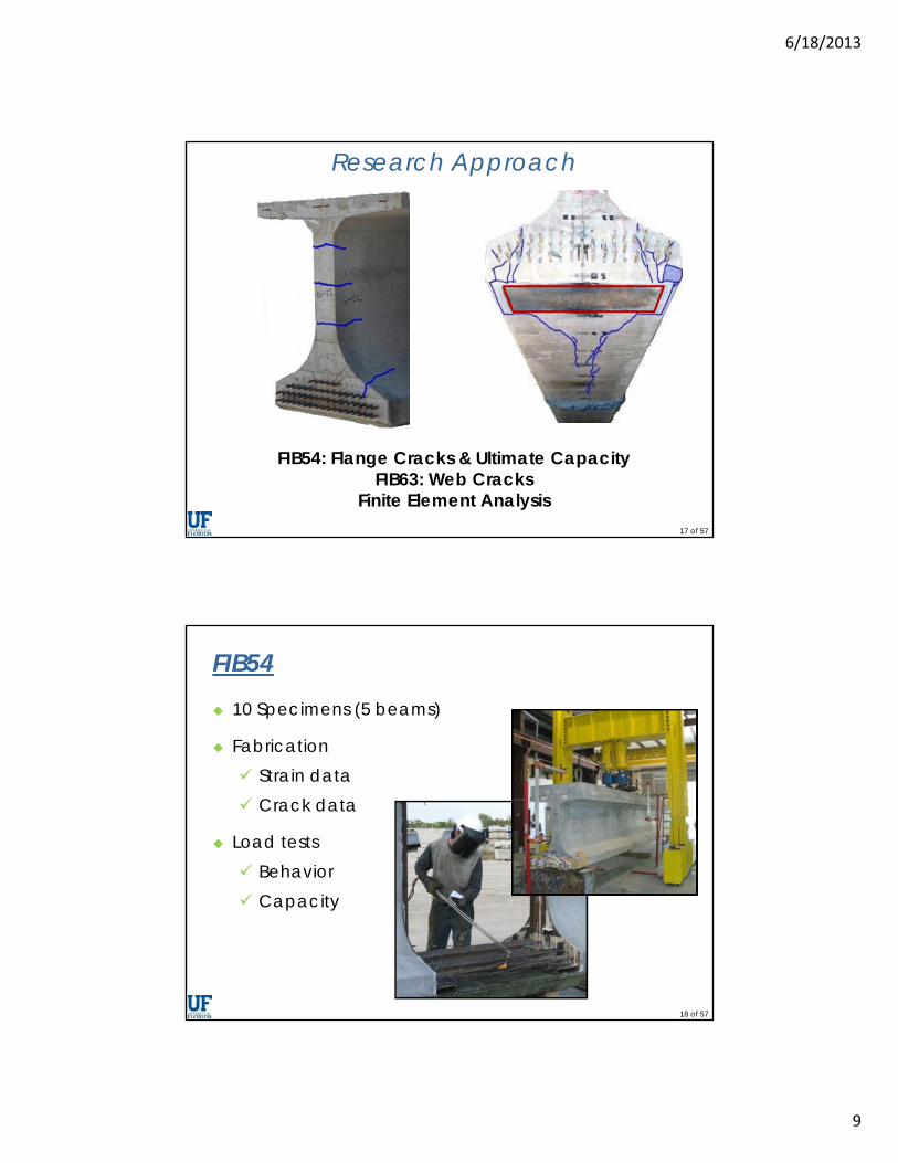
Research Approach
FIB54: Flange Cracks & Ultimate CapacityFIB63: Web Cracks
Finite Element Analysis
18 of 57
FIB54 10 Specimens (5 beams)
Fabrication Strain data Crack data
Load tests Behavior Capacity
6/18/2013
10
19 of 57
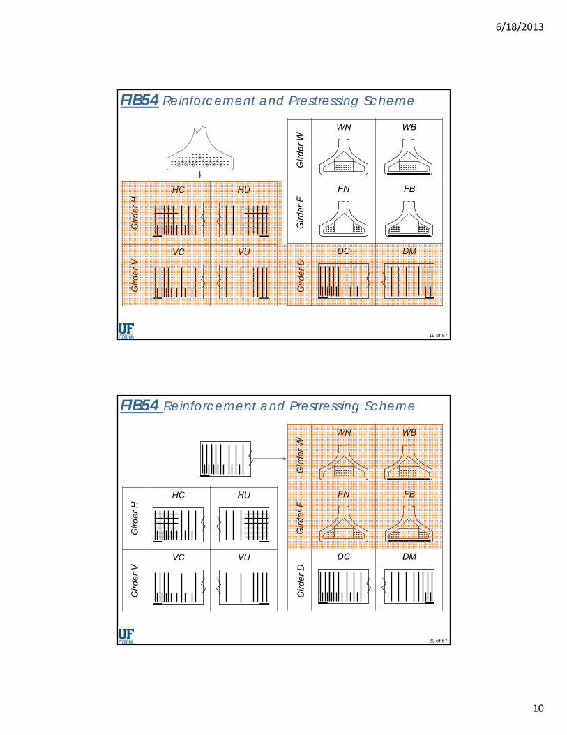
FIB54 Reinforcement and Prestressing Scheme
20 of 57
FIB54 Reinforcement and Prestressing Scheme
6/18/2013
11
21 of 57
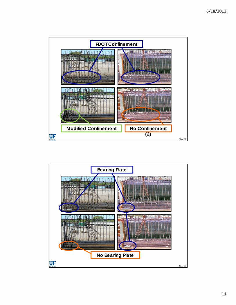
FDOT Confinement
Modified Confinement No Confinement (2)
22 of 57
No Bearing Plate
Bearing Plate
6/18/2013
12
23 of 57
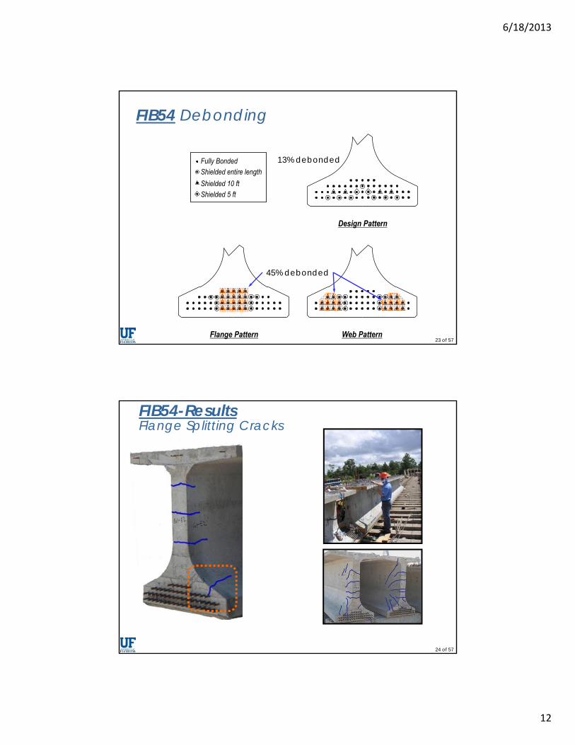
FIB54 Debonding
45% debonded
13% debonded
24 of 57
FIB54-ResultsFlange Splitting Cracks
6/18/2013
13
25 of 57
26 of 57
6/18/2013
14
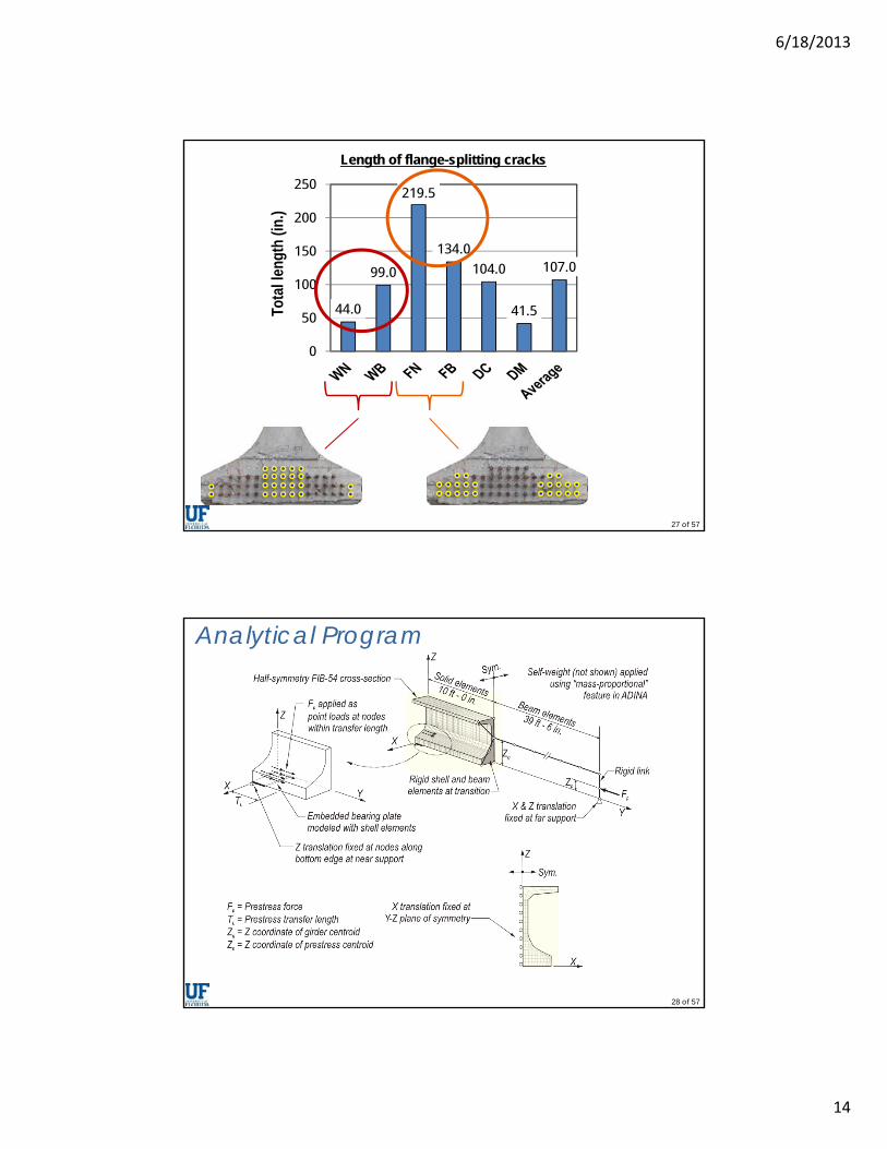
27 of 57
44.0
99.0
219.5
134.0
104.0
41.5
107.0
0
50
100
150
200
250
Tota
l len
gth
(in.)
Length of flange-splitting cracks
28 of 57
Analytical Program
6/18/2013
15
29 of 57
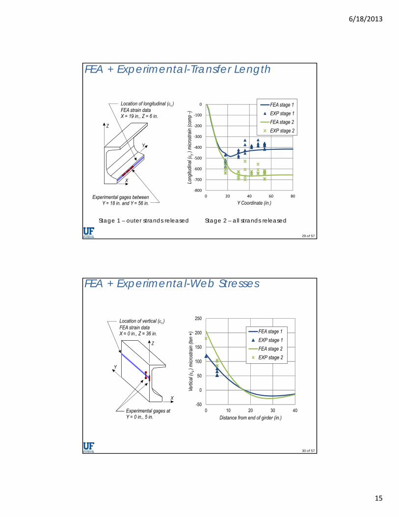
FEA + Experimental-Transfer Length
Stage 1 – outer strands released Stage 2 – all strands released
30 of 57
FEA + Experimental-Web Stresses
6/18/2013
16
31 of 57
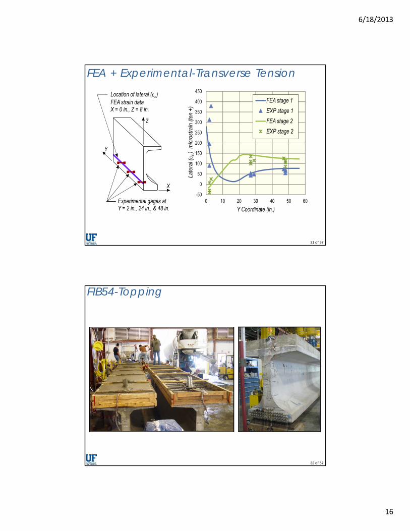
FEA + Experimental-Transverse Tension
32 of 57
FIB54-Topping
6/18/2013
17
33 of 57
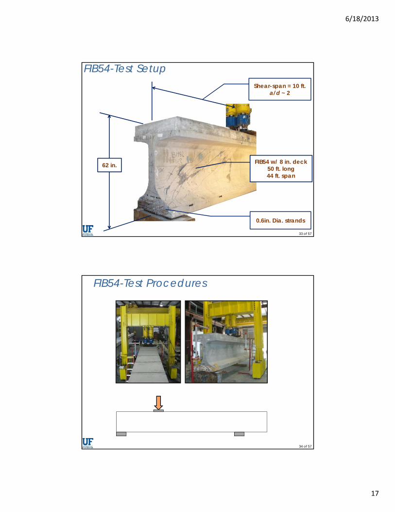
Shear-span = 10 ft.a/d ~ 2
FIB54 w/ 8 in. deck50 ft. long44 ft. span
62 in.
0.6in. Dia. strands
FIB54-Test Setup
34 of 57
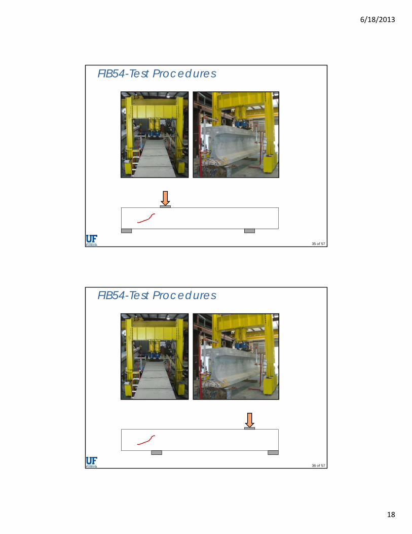
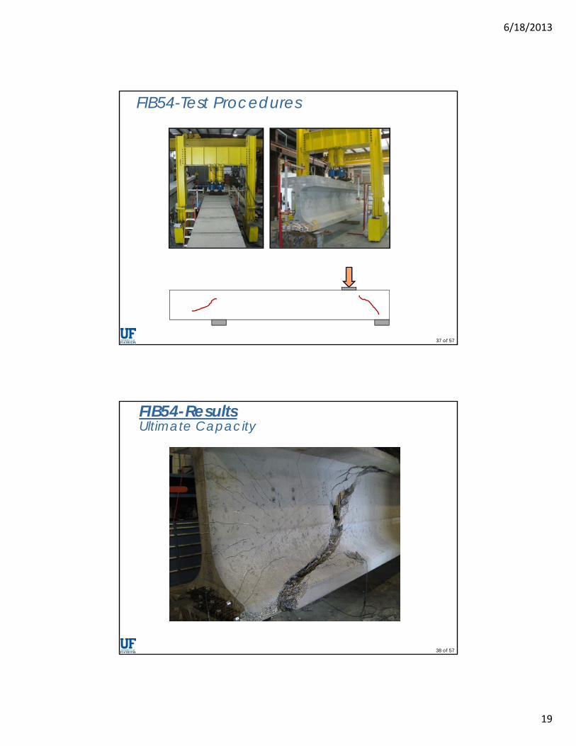
FIB54-Test Procedures
6/18/2013
18
35 of 57
FIB54-Test Procedures
36 of 57
FIB54-Test Procedures
6/18/2013
19
37 of 57
FIB54-Test Procedures
38 of 57
FIB54-ResultsUltimate Capacity

6/18/2013
20
39 of 57
Lateral-Splitting(4) specimens
Failure Modes
Web-Shear(4) specimens
Bond-Shear(2) specimens
40 of 57
Displacement / Slip (in.)
Supe
rimpo
sed
Shea
r (ki
p)
0 0.25 0.5 0.75 1 1.250
100
200
300
400
500
600
700
FNFB WN
WB
Vn = 454kACI
Vn = 528kAASHTO
Bond-shear
Lateral-splitting
Ultimate Capacity
6/18/2013
21
41 of 57
766
666 698635
508
612
375409
753703
0
100
200
300
400
500
600
700
800
900
HC HU VC VU WN WB FN FB DC DM
Max
imu
m S
hea
r (k
ip)
Lateral-splitting failure
42 of 57
Ultimate Capacity-Transverse Strain
6/18/2013
22
43 of 57
14.0
4.4
10.0
29.8
13.1
35.8
12.8
0
5
10
15
20
25
30
35
40
WN WB FN FB
Ave
rag
e st
ress
(ks
i)
V = 375 kip
Ultimate
Includes stress from loading & prestressing
Ultimate Capacity-Transverse StrainSt
ress
in
conf
inem
ent
rein
forc
emen
t
44 of 57
Ultimate Capacity-Transverse Strain
6/18/2013
23
45 of 57
75.978.8
74.9
44.2
72.178.5
70.773.070.1
63.9
37.0
57.9 59.7 60.3
0
20
40
60
80
100
HC VC WB FB DC DM Avg.
% of tran
sverse (x‐x) force
carried by bearing plate
V=375
Ultimate
Ultimate Capacity-Transverse Strain
46 of 57
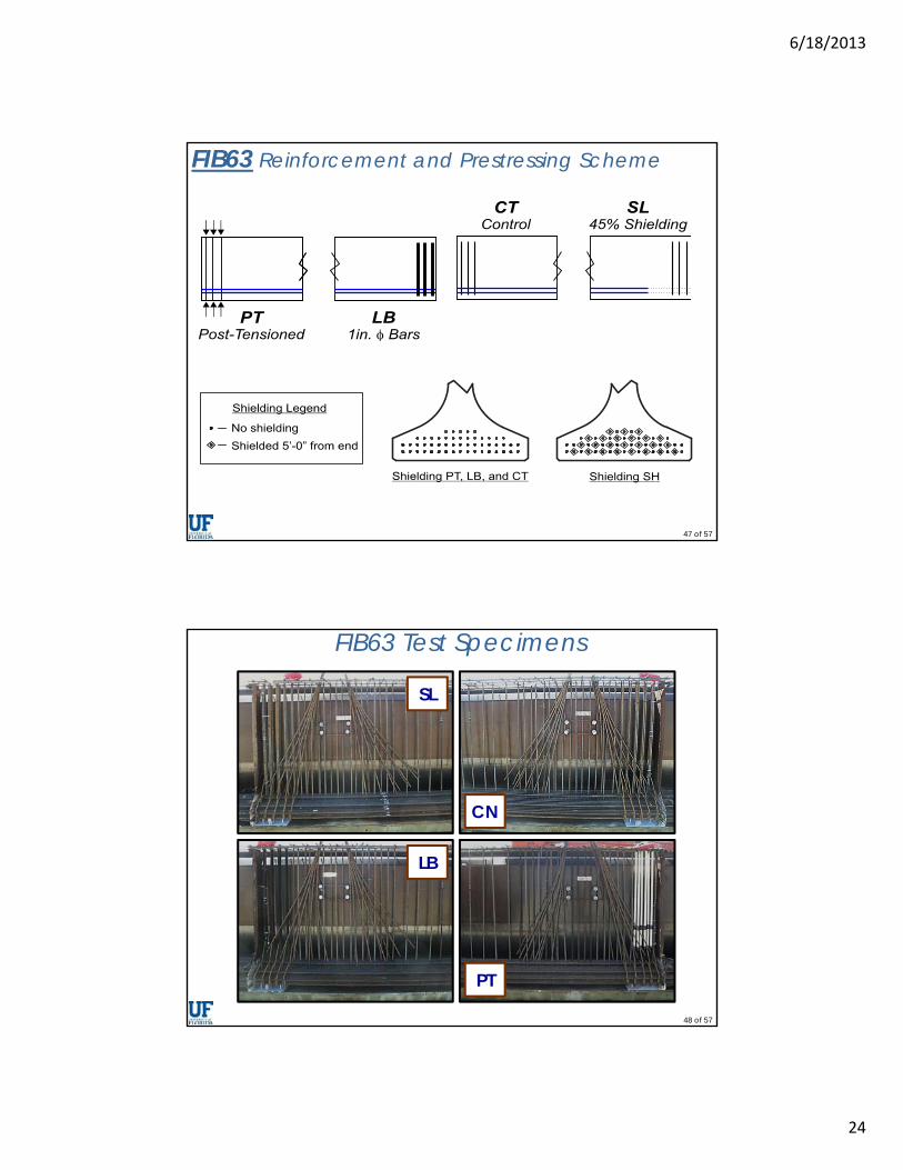
FIB63 4 specimens (2 beams)
Monitor cracks after release
Load test
6/18/2013
24
47 of 57
FIB63 Reinforcement and Prestressing Scheme
48 of 57
FIB63 Test Specimens
SL
CN
LB
PT
6/18/2013
25
49 of 57
2 ksi
0 ksi
-2 ksi
-4 ksi
-6 ksi
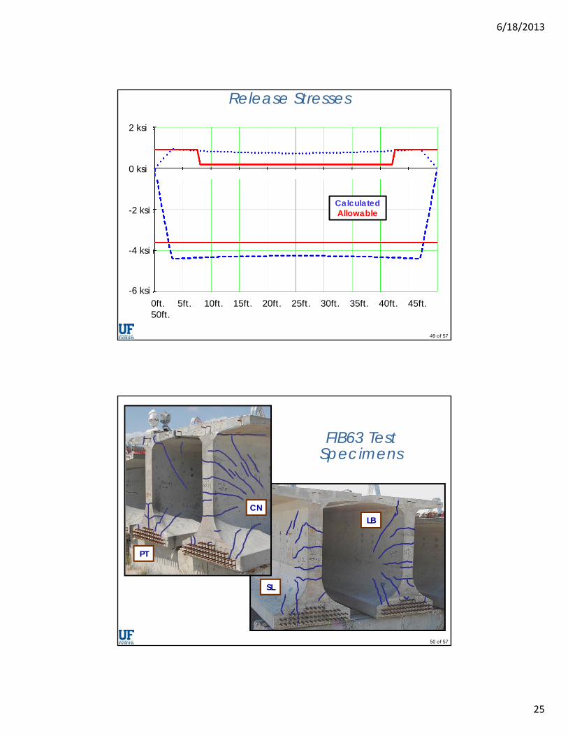
Release Stresses
CalculatedAllowable
0ft. 5ft. 10ft. 15ft. 20ft. 25ft. 30ft. 35ft. 40ft. 45ft. 50ft.
50 of 57
SL
CNLB
PT
FIB63 Test Specimens
6/18/2013
26
51 of 57
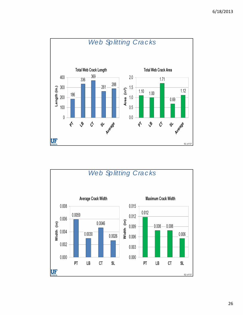
Web Splitting Cracks
52 of 57
Web Splitting Cracks
6/18/2013
27
53 of 57
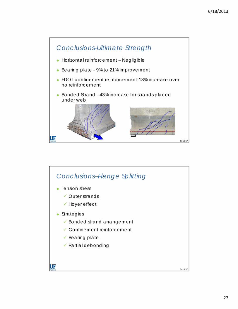
Conclusions-Ultimate Strength
Horizontal reinforcement – Negligible
Bearing plate - 9% to 21% improvement
FDOT confinement reinforcement-13% increase over no reinforcement
Bonded Strand - 43% increase for strands placed under web
54 of 57
Conclusions–Flange Splitting
Tension stress Outer strands Hoyer effect
Strategies Bonded strand arrangement Confinement reinforcement Bearing plate Partial debonding
6/18/2013
28
55 of 57
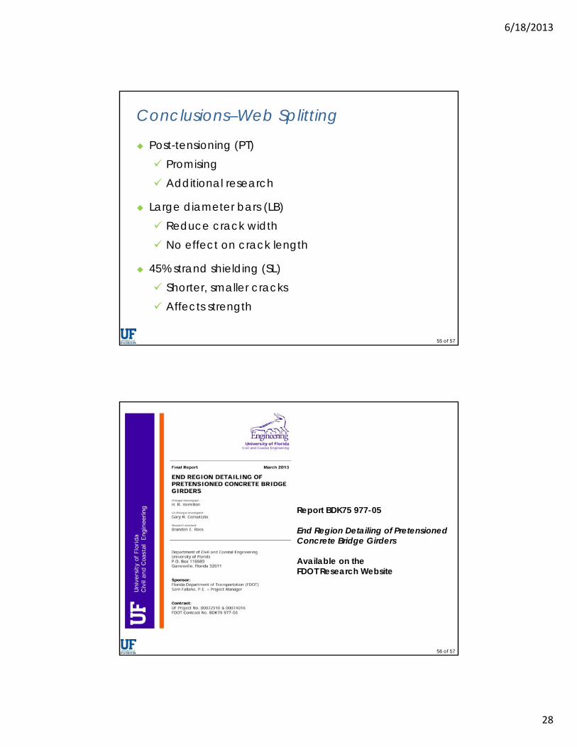
Conclusions–Web Splitting
Post-tensioning (PT) Promising Additional research
Large diameter bars (LB) Reduce crack width No effect on crack length
45% strand shielding (SL) Shorter, smaller cracks Affects strength
56 of 57
Report BDK75 977-05
End Region Detailing of Pretensioned Concrete Bridge Girders
Available on theFDOT Research Website
6/18/2013
29
57 of 57
Thank You Experimental work conducted at
M. H. Ansley Structures Research Center Many thanks to Sam Fallaha and the Center’s
staff! David Allen Adam Brennan Frank Cobb Steve Eudy Tony Hobbs Will Potter Paul Tighe David Wagner Chris Weigly Steven Nolan, P.E., FDOT Structures Design Office
58 of 57
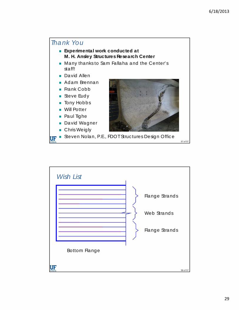
Wish List
Bottom Flange
Flange Strands
Flange Strands
Web Strands