Embed Size (px)
Citation preview
Manuscript submitted to IEEE/ACM Transaction on Networking
1
Abstract—One of the headache problems in high performance
computing area is the lack of a transport protocol to transfer bulk data fast over computational grids. TCP, the de facto transport protocol of the Internet, fails to utilize the abundant optical bandwidth efficiently. It also has unfairness problem of RTT bias that can lead to performance drop for distributed applications. This paper presents an end-to-end approach to address these efficiency and fairness problems, especially over high bandwidth-delay product networks. This congestion control algorithm combines rate based and window based control mechanisms. It deploys selective acknowledgement, constant synchronization time, bandwidth measurement, as well as packet delay monitoring to support the rate and window control. Both the theoretical analysis and simulation/implementation results have shown the algorithm satisfies the objectives of high performance, intra-protocol fairness, TCP-friendliness, and stability.
Index Terms—Congestion control, end-to-end approach, high bandwidth-delay product networks, transport protocol.
I. INTRODUCTION HOTONIC technology has pushed the network bandwidth to 10Gbps and enabled a wide range of new, powerful
applications, including high resolution streaming media, remote access to scientific instruments, and specialized virtual-reality such as tele-immersion.
The pattern of data flow over these high speed wide area networks, or high bandwidth-delay product (BDP) networks, is quite different from that on the commercial Internet. The de facto standard transport protocol of TCP over the Internet utilizes the backbone bandwidth with multiplexed large amounts of concurrent flows, most of which are short life burst traffic [35]. However, in computational grids, it is often the case that a small number of bulk sources share the abundant optical bandwidth [18].
The window based AIMD (additive increase multiplicative decrease) control algorithm of TCP suffers more from random loss as the BDP increases to higher [19, 22]. Its congestion avoidance mechanism takes too long a time to fully probe the
Manuscript received Aug. 1, 2003. This work was supported by the National Science Foundation under grant ANI-9977868.
The authors are with the Laboratory for Advanced Computing, University of Illinois at Chicago, Chicago, IL 60607, USA (phone: 312-996-0305; fax: 312-355-0373; e-mail: [email protected], [email protected]).
Robert L. Grossman is also with the Two Cultures Group, Chicago, IL 60607, USA.
bandwidth. The continuous packet loss is another disaster to TCP in high BDP networks, which can decrease the window size to a very small value and then takes substantial time to recover [19]. These drawbacks have been convinced in real network experiments [22].
Moreover, TCP also has fairness problem of RTT (round trip time) bias. When TCP flows with different RTTs share the same bottleneck link, flows with shorter RTTs will occupy more bandwidth than flows with longer RTTs [6, 19, 21, 22]. This problem is particular critical in many high performance applications. For example, in streaming join, the performance is limited by the slowest data stream [29].
Network researchers have put out series of solutions, including enhancement to TCP [2, 4, 5, 17, 26, 27] and new transport layer protocols [6, 24, 25]. Due to the time and financial cost of standardization and system upgrade (especially for those open looped control mechanisms), most of them have not been deployed widely yet and are not likely in the near future. Although some applications have used parallel TCP [28] for high performance data transfer, it does not solve all the TCP problems and is too aggressive to regular TCP flows [28]. A new end-to-end approach is necessary to be invented to support those high performance data intensive distributed applications. An end-to-end congestion control algorithm can be implemented at application layer (e.g., using UDP as lower layer transport) such that it can be deployed without any modification to the operating system and network infrastructure. Moreover, the approach can be used in peer-to-peer or overlay networks to serve as high performance data transfer service layer.
This paper presents such a congestion control algorithm that has been implemented in a high performance data transport protocol named UDT, or UDP based Data Transfer protocol, which is a reliable application layer protocol over UDP. In the rest of the paper we refer the congestion control algorithm to be described as the UDT algorithm.
The algorithm uses rate based control for inter-packet time and a window based control for number of unacknowledged packets. The rate control algorithm is AIMD, where the increase parameter is related to estimated available bandwidth and the decrease factor is constant and fixed. UDT can utilize almost full bandwidth even at 1 Gbps link capacity and 100ms RTT environment (between Chicago and Amsterdam []). Meanwhile, it is still fair to concurrent UDT and TCP flows, if there is any.
End-to-End Congestion Control for High Performance Data Transfer
Yunhong Gu, Student Member, IEEE and Robert L. Grossman, Member, IEEE
P

Manuscript submitted to IEEE/ACM Transaction on Networking
2
In section 2 we will explain in detail the requirements of the algorithm and the design rationale. The algorithm is described in section 3 and a theoretical analysis with simulation results is given in section 4. Section 5 discusses the limitations of UDT algorithm and possible improvements in future. We also give some implementation results in real high speed networks in section 6. Section 7 introduces relevant research work. The paper is concluded in section 8. There is also a description of several critical implementation issues in the appendix.
II. DESIGN RATIONALE The basic requirement comes from the need of fast transfer
of bulk data over high BDP networks. So efficiency is one of the most important objectives in the UDT algorithm. It should probe the available bandwidth fast and recover fast from a loss event. Both single UDT flow and multiplexed parallel flows should utilize the bandwidth efficiently. Efficiency objective also means that given the bit error rate of current wired links, UDT can utilize most of the bandwidth.
Intra-protocol fairness is another rule that must be obeyed. Particularly, fairness should be independent to network delay or RTT, since any kind of unfairness can cause decreases in applications’ throughput.
It should also be friendly to TCP, since today most of the flows on Internet are TCP flows [35]. However, it is hard to define a quantitative TCP friendliness rule by which UDT and TCP share the bandwidth, because TCP can be inefficient in high BDP link and it is not RTT independent. Although there has been a model to quantify TCP’s throughput [21], using this model to limit the new protocol’s throughput is improper since it is contradict with the efficiency and intra-protocol fairness objectives discussed above.
According to this background, we define the TCP friendliness rule that constraints the design of UDT algorithm as below:
When same number of UDT flows and TCP flows share the same bottleneck link, UDT cannot occupy more bandwidth than TCP, unless it is because TCP’s own inefficiency. In the latter case, UDT can utilize the bandwidth that TCP fails to occupy.
The algorithm must be stable at any network scenarios and can converge fast to efficiency and fairness equilibrium from any state. Particularly, congestion collapse [16] must be avoided.
Furthermore, the data transfer is required to be reliable. So reliability is yet another rule to obey.
Finally, the design must consider implementation efficiency and difficulties. Overhead of computation, packet header and control packets should be as few as possible since high performance data transfer is also a CPU intensive job and the computation overhead can limit the throughput or cause packet loss (because CPU is too busy to process the incoming packets in time).
Rate based congestion control has been regarded as a better method than window based control for high performance [18].
However, there must be a threshold to limit the number of unacknowledged packets to reduce the packet loss over high BDP networks, where large amounts of packets have been sent out before the sender learns congestion. We use a dynamic window as this threshold value. The scheme to update the window size is called flow control in UDT.
To utilize the bandwidth efficiently, it is necessary to know the available bandwidth, which has been proposed in [2] for TCP improvements. In UDT we use bandwidth estimation to decide the increase parameter in rate control.
To reach RTT independence, it is natural to use a constant control interval instead of any values related to RTT, which has been proposed in [15]. Moreover, this is also an effective method to reach fast recovery from loss over long RTT link.
Since it is hard to take as same bandwidth as TCP does, we choose to let UDT take less when competing with coexisting TCP flows. By always adapting to available bandwidth, UDT might be friendlier than TCP’s blind increase/decrease.
Using delay can help to reduce loss and persistent queue size caused by rate control, so it increases performance and fairness. However, delay can be misestimated in real networks, so it is only a supportive method in UDT, i.e., it helps to reach higher efficiency and fairness, but even it fails, the rate and flow control can still work well at least at an acceptable level.
III. ALGORITHM
A. Overview The basic mechanism of the algorithm is to control the
inter-packet time (rate control) and the number of unacknowledged packets (flow control). Rate control is triggered by a timer at every constant synchronization interval (SYN), whereas flow control is triggered by every arrived positive acknowledgement (ACK).
The constant SYN interval is 0.01 seconds, which is a tradeoff between efficiency, fairness and stability. Smaller value can increase the sending rate faster, but it is more aggressive and may be instable in very long RTT network. Given a practical value of RTT of the longest link can have in the near future, which may be several seconds, the 0.01s SYN interval is acceptable for stability.
The acknowledgement is selective, which is sent every constant interval same as SYN time but is controlled by a different timer. UDT also uses explicit negative feedback, or NAK, which is sent once a packet loss is detected, or resent at timer triggered event if necessary.
UDT always try to pack application data at MTU (maximum transfer unit) size (including packet header) if possible, and never exceeds it. In this paper, we use packets and number of packets per second to measure window size and transfer speed, where a packet is with the size of MTU, unless the data is explicitly followed by a unit. It is easy to translate the UDT algorithm to a byte based approach. However, for high performance bulk data transfer, packet based scheme is more efficient.
Manuscript submitted to IEEE/ACM Transaction on Networking
3
To help to describe the algorithm, we use sender and receiver to represent the protocol entities sending data and receiving data, respectively. Only data transfer in single direction is discussed, the situation in opposite direction is symmetrical.
B. Flow Control The receiver calculates packet arrival speed (AS) and sends it
back within ACK packets. When receiving an ACK packet and the AS value in the ACK is greater than 0, the sender updates its window size W by:
W = W * α + AS * (RTT + SYN) * (1 - α). (1) In UDT α is 0.875, which is the trade-off between history
effect and implementation efficiency. The value is used in all EWMA (exponential weighted moving average) equations in UDT.
The packet arrival speed is calculated with the following algorithm:
The receiver records the arrival intervals of incoming data packets. Once an ACK is to be sent, it finds the median M of the most recent N0 intervals (N0 is 16 in the current specification and implementation), and removes those values which are either greater than 8M or less than M/8. If more than half of the values left, the receiver calculates the average value of the rest packet arrival intervals and then gets the packet arrival speed (in number of packets per second). Otherwise, 0 is returned.
C. Rate Control Every SYN time, the sender calculates the moving average
of the loss rate during the most recent SYN interval from the number of losses in NAK packets and the total number of packets it has sent out. If the loss rate is less than a small threshold (1%), the number of packets to be increased per SYN time (inc) is calculated by the following algorithm: if (B <= C)
MTUinc /1= (2) else if (C < D)
⎡ ⎤ )/1,/10max( 89/log10 MTUMTUinc MTUB β×= ×× (3) else
⎡ ⎤ )/1,/10max( 8)(log10 MTUMTUinc MTUCB β×= ××− (4) where B is the estimated end-to-end link capacity, C is the
current sending rate, and D is the sending rate when last time a decrease occurs. β is a constant empirical value of 1.5 * 10-6.
The inter-packet time I is then recalculated according to: I = SYN/(SYN/I + inc) (5) Sending rate will not be increased if the loss rate is not less
than the threshold. This algorithm tries to speculate the available bandwidth B’
(in bytes per second) in the link. Since the sending rate is decreased by 1/9 (refer to decrease algorithm below), after a decrease, the available bandwidth is estimated as B/9*MTU. Otherwise B’ is (B – C)*MTU, supposing all the rest bandwidth is available. It then classifies B’ into different levels of 10’s power P, and then P is used to decide how many packets can be increased in the next SYN time. However, the minimum
increase is 1 byte, or 1/MTU packets. Although B’ may be greater than real available bandwidth, it
is consistent in all concurrent flows, which is very important to reach fairness. This will be further discussed later in section 5.
The end-to-end capacity is probed by sampled UDT data packets. Every N1 packets (N1 is 16 in the current specification and implementation), the sender does not wait to the next packet sending time but sends the next packet immediately, such that the two continuous packets form a probing packet pair [1, 8, 9]. The receiver records the arrival time between this packet pair in a history window. Once an ACK is to be sent, it calculates the median of the last N2 arrival intervals of the probing packet pairs MP (N2 is 16 in the current specification and implementation; At the beginning of a UDT session, when there is less than N2 packet pairs in total, only use the current available values), then the new estimated bandwidth NB (= 1/MP), and sends it to its peer side within the ACK packet. At the sender side, after receiving an ACK, the estimated link capacity is updated by:
B = B * α + NB * (1 – α). (6) In UDT, both packet loss and packet delay are used as the
indications of congestion. UDT measures RTT variation to check packet delay
increasing trend. The sender sends back an ACK2 for each received ACK, as the acknowledgement to the ACK. Every ACK is assigned a unique sequence number independent from data sequence number, so that the receiver can match the ACK and ACK2 accurately. When an ACK2 is received and new RTT is calculated from the time when the ACK is sent and the time when the ACK2 is received, UDT uses the last N3 (N3 is 16 in the current specification and implementation) RTT values recorded in a history window (NOT the averaged value, which is estimated RTT value used to calculate timeout interval in UDT) to check delay increasing trend with the method of PCT (pairwise comparison test) and PDT (pairwise difference test) described in Pathload [7]. If an increasing trend in packet delays is detected, a warning message is sent to the sender but no more than 1 warning packet will be sent in 2 RTTs.
Once the sender receives a delay warning message, it updates the inter-packet time by:
I = I * 1.125 (7) Meanwhile, it records the current largest sequence number
that has been sent out (last_dec_seq), and reset the decrease count dc to 1, threshold parameter e to 4.
When the sender receives an NAK, it checks if the last lost sequence number in the packet is greater than last_dec_seq. If the condition is satisfied, it takes the same action as when it receives delay warning. Otherwise it increases dc by 1, and takes (7) only if dc == 2e. Once (7) is taken, e is increased by 1.
Each time the variable of last_dec_seq is updated, data sending is frozen for SYN time, i.e., no packet will be sent out during the next SYN time. This is to help clear the congested queue.
Note that formula (6) is equivalent to decrease the sending rate by 1/9.
Manuscript submitted to IEEE/ACM Transaction on Networking
4
D. Slow Start The window size is initialized to 2 and updated to the number
of acknowledged packets for every ACK packet until the sender receives a loss report or a delay warning, when slow start ends. The inter-packet time is 0 during the slow start phase and updated to packet arrival interval at the end of the phase. In UDT, slow start only occurs at the beginning of a session.
E. Feedback Intervals There are 3 kinds of feedbacks needed in UDT: ACK/ACK2,
NAK, and delay warning message. ACK is triggered every SYN time, but only when there are
new received packets to acknowledge. The sender sends an ACK2 packet as the acknowledgement to the ACK to the receiver. The receiver can learn what is the largest sequence number prior to that the sender has been acknowledged, so it can avoid to send out unnecessary ACKs. On the other hand, if an ACK carries the same sequence number as that of the previous one, the interval between these two ACKs must be at least 2 RTTs.
The higher the sending rate is, the less ratio of bandwidth cost by ACK/ACK2. In the worst case, when the sending rate is very low (no more than 1 packet is sent in 1 SYN time), there is equal number of ACK and ACK2 packets to the number of data packets. If the transfer speed is 1 Gbps and MTU is 1500 bytes, there is only 1 ACK and 1 ACK2 for every 833 data packets.
NAK is triggered when an NAK timer is expired or when loss is detected during data receiving. In the former case, the data structure that records the loss (herefrom we call it loss list) is checked and those packets whose last NAK report times are at least k RTTs before are chosen and sent back, where k is initialized to 2 and increased by 1 each time the packet is reported. In the latter case, only the loss detected by the current packet is sent back. Loss information is compressed in NAK, and only those can be contained in 1 NAK packet are sent, whereas the others may be sent in a future packet if necessary.
NAK is generated only if there is loss to report. In the worst case, there are as half number of immediate NAKs as data packets when every other packet got lost during congestion. The possibility of this situation is very small since loss is often continuous. The NAK interval is the larger between RTT and average data arrival interval since last SYN time so that no more control packets are generated than data packets. Meanwhile, the NAK interval for every lost packet increases each time so that the sender will not be too busy with processing NAK to send out any packets.
A warning message is sent back once the receiver detects an increasing trend in RTT, which is checked after each ACK2 is received. No more than 1 delay warning is fed back in 2 RTTs, giving enough time for the sender to clear the congestion.
IV. THEORETICAL ANALYSIS
A. Efficiency In UDT, the throughput is mainly decided by rate control in
steady state, whereas flow control can help to reduce loss during congestion.
If congestion can be cleared by a single drop of sending rate, then the bandwidth utilization is at least 94.4 (= 2 / (1 + 8/9)) during the post-slow-start phase. This is satisfied if
1. The number of packet loss event is not large enough to cause multiple drops (< 24).
2. The BDP is not so large that a single drop cannot neutralize the effect of the increases since last drop.
These conditions are affected by RTT, queue management and number of concurrent flows.
Long RTT is the major reason that causes continuous sending rate decrease, since it needs long time to feed back the loss information from the receiver.
Active queue management can drop a packet before the queue overflows. However, this may not affect UDT much since UDT’s smooth flow has good statistical manner for queue managements. We will discuss the impact of queue size and management schemes later in this section.
Furthermore, as the number of concurrent flows increases, throughput of a single flow decreases, but the increase per flow keeps unchanged as same as a single flow does, since the available bandwidth estimation is made by a flow’s own rate and the link capacity.
The analysis above omits the effect of increasing trend detection in packet delays. By using delay as one of the congestion indications, loss can be further reduced as well as decreases of sending rate.
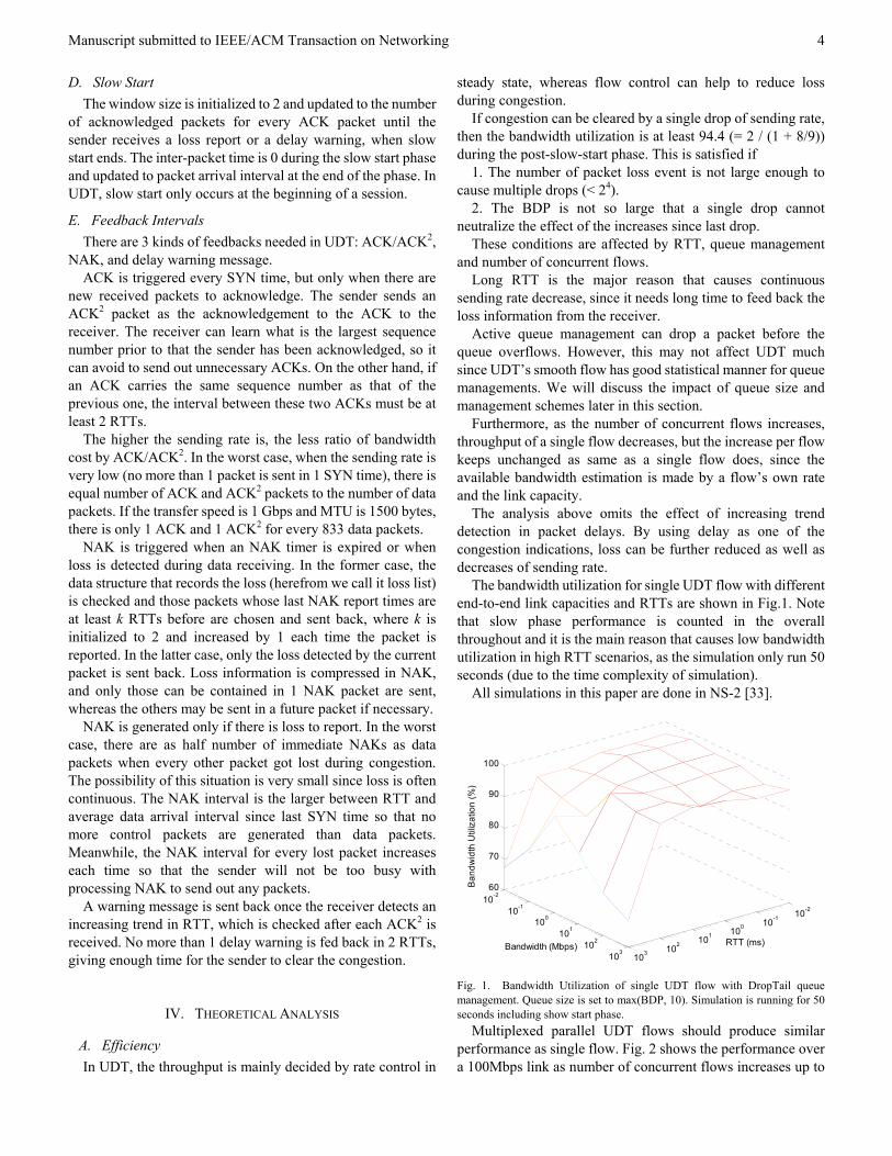
The bandwidth utilization for single UDT flow with different end-to-end link capacities and RTTs are shown in Fig.1. Note that slow phase performance is counted in the overall throughout and it is the main reason that causes low bandwidth utilization in high RTT scenarios, as the simulation only run 50 seconds (due to the time complexity of simulation).
All simulations in this paper are done in NS-2 [33].
10-2
10-1
100
101
102
103
10-2
10-1
100
101
102
103
60
70
80
90
100
RTT (ms)Bandwidth (Mbps)
Ban
dwid
th U
tiliz
atio
n (%
)
Fig. 1. Bandwidth Utilization of single UDT flow with DropTail queue management. Queue size is set to max(BDP, 10). Simulation is running for 50 seconds including show start phase.
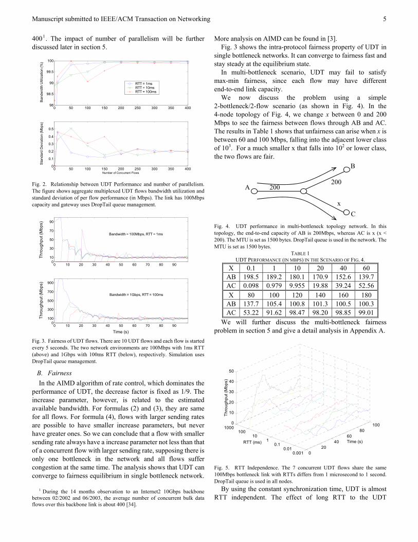
Multiplexed parallel UDT flows should produce similar performance as single flow. Fig. 2 shows the performance over a 100Mbps link as number of concurrent flows increases up to
Manuscript submitted to IEEE/ACM Transaction on Networking
5
4001. The impact of number of parallelism will be further discussed later in section 5.
0 50 100 150 200 250 300 350 40098
98.5
99
99.5
100
Ban
dwid
th U
tiliz
atio
n (%
)
RTT = 1msRTT = 10msRTT = 100ms
0 50 100 150 200 250 300 350 4000
0.1
0.2
0.3
0.4
0.5
Number of Concurrent Flows
Sta
ndar
d D
evia
tion
(Mbp
s)
Fig. 2. Relationship between UDT Performance and number of parallelism. The figure shows aggregate multiplexed UDT flows bandwidth utilization and standard deviation of per flow performance (in Mbps). The link has 100Mbps capacity and gateway uses DropTail queue management.
0 10 20 30 40 50 60 70 80 900
10
30
50
70
90
Thro
ughp
ut (M
bps)
0 10 20 30 40 50 60 70 80 900
100
300
500
700
900
Time (s)
Thro
ughp
ut (M
bps)
Bandwidth = 100Mbps, RTT = 1ms
Bandwidth = 1Gbps, RTT = 100ms
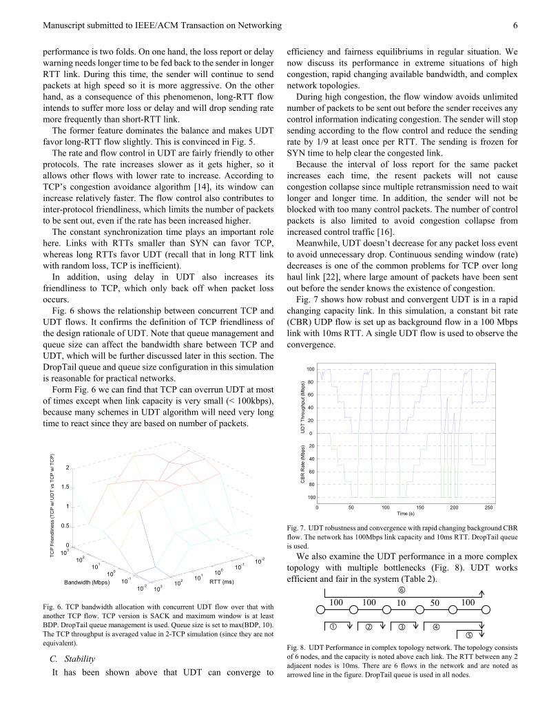
Fig. 3. Fairness of UDT flows. There are 10 UDT flows and each flow is started every 5 seconds. The two network environments are 100Mbps with 1ms RTT (above) and 1Gbps with 100ms RTT (below), respectively. Simulation uses DropTail queue management.
B. Fairness In the AIMD algorithm of rate control, which dominates the
performance of UDT, the decrease factor is fixed as 1/9. The increase parameter, however, is related to the estimated available bandwidth. For formulas (2) and (3), they are same for all flows. For formula (4), flows with larger sending rates are possible to have smaller increase parameters, but never have greater ones. So we can conclude that a flow with smaller sending rate always have a increase parameter not less than that of a concurrent flow with larger sending rate, supposing there is only one bottleneck in the network and all flows suffer congestion at the same time. The analysis shows that UDT can converge to fairness equilibrium in single bottleneck network.
1 During the 14 months observation to an Internet2 10Gbps backbone between 02/2002 and 06/2003, the average number of concurrent bulk data flows over this backbone link is about 400 [34].
More analysis on AIMD can be found in [3]. Fig. 3 shows the intra-protocol fairness property of UDT in
single bottleneck networks. It can converge to fairness fast and stay steady at the equilibrium state.
In multi-bottleneck scenario, UDT may fail to satisfy max-min fairness, since each flow may have different end-to-end link capacity.
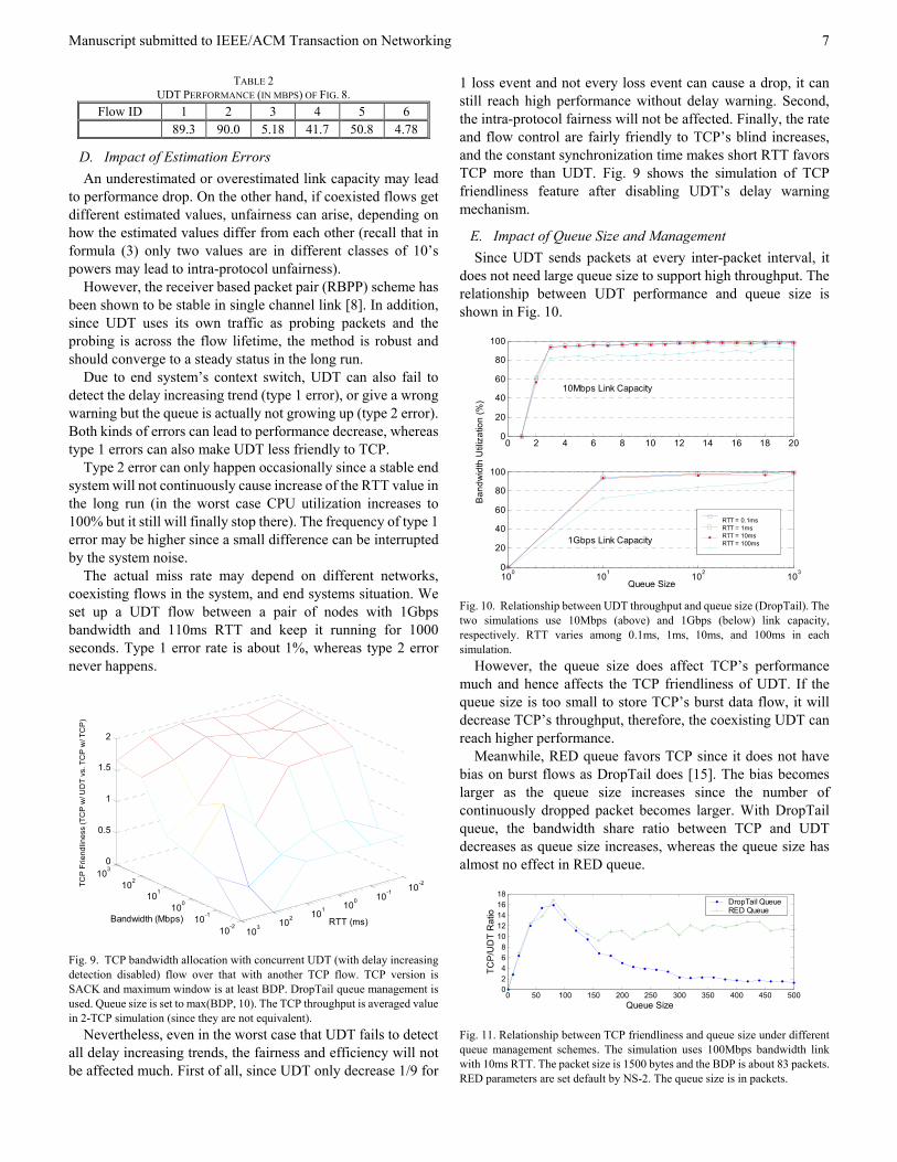
We now discuss the problem using a simple 2-bottleneck/2-flow scenario (as shown in Fig. 4). In the 4-node topology of Fig. 4, we change x between 0 and 200 Mbps to see the fairness between flows through AB and AC. The results in Table 1 shows that unfairness can arise when x is between 60 and 100 Mbps, falling into the adjacent lower class of 103. For a much smaller x that falls into 102 or lower class, the two flows are fair.
Fig. 4. UDT performance in multi-bottleneck topology network. In this topology, the end-to-end capacity of AB is 200Mbps, whereas AC is x (x < 200). The MTU is set as 1500 bytes. DropTail queue is used in the network. The MTU is set as 1500 bytes.
TABLE 1 UDT PERFORMANCE (IN MBPS) IN THE SCENARIO OF FIG. 4.
X 0.1 1 10 20 40 60 AB 198.5 189.2 180.1 170.9 152.6 139.7AC 0.098 0.979 9.955 19.88 39.24 52.56X 80 100 120 140 160 180
AB 137.7 105.4 100.8 101.3 100.5 100.3AC 53.22 91.62 98.47 98.20 98.85 99.01
We will further discuss the multi-bottleneck fairness problem in section 5 and give a detail analysis in Appendix A.
020
4060
80100
0.0010.01
0.11
10100
10000
10
20
30
40
50
Time (s)RTT (ms)
Thro
ughp
ut (M
bps)
Fig. 5. RTT Independence. The 7 concurrent UDT flows share the same 100Mbps bottleneck link with RTTs differs from 1 microsecond to 1 second. DropTail queue is used in all nodes.
By using the constant synchronization time, UDT is almost RTT independent. The effect of long RTT to the UDT
A
x
200200
B
C
Manuscript submitted to IEEE/ACM Transaction on Networking
6
performance is two folds. On one hand, the loss report or delay warning needs longer time to be fed back to the sender in longer RTT link. During this time, the sender will continue to send packets at high speed so it is more aggressive. On the other hand, as a consequence of this phenomenon, long-RTT flow intends to suffer more loss or delay and will drop sending rate more frequently than short-RTT link.
The former feature dominates the balance and makes UDT favor long-RTT flow slightly. This is convinced in Fig. 5.
The rate and flow control in UDT are fairly friendly to other protocols. The rate increases slower as it gets higher, so it allows other flows with lower rate to increase. According to TCP’s congestion avoidance algorithm [14], its window can increase relatively faster. The flow control also contributes to inter-protocol friendliness, which limits the number of packets to be sent out, even if the rate has been increased higher.
The constant synchronization time plays an important role here. Links with RTTs smaller than SYN can favor TCP, whereas long RTTs favor UDT (recall that in long RTT link with random loss, TCP is inefficient).
In addition, using delay in UDT also increases its friendliness to TCP, which only back off when packet loss occurs.
Fig. 6 shows the relationship between concurrent TCP and UDT flows. It confirms the definition of TCP friendliness of the design rationale of UDT. Note that queue management and queue size can affect the bandwidth share between TCP and UDT, which will be further discussed later in this section. The DropTail queue and queue size configuration in this simulation is reasonable for practical networks.
Form Fig. 6 we can find that TCP can overrun UDT at most of times except when link capacity is very small (< 100kbps), because many schemes in UDT algorithm will need very long time to react since they are based on number of packets.
10-2
10-1
100
101
102
10310-210-1
100101
102103
0
0.5
1
1.5
2
RTT (ms)Bandwidth (Mbps)
TCP
Frie
ndlin
ess
(TC
P w
/ UD
T vs
TC
P w
/ TC
P)
Fig. 6. TCP bandwidth allocation with concurrent UDT flow over that with another TCP flow. TCP version is SACK and maximum window is at least BDP. DropTail queue management is used. Queue size is set to max(BDP, 10). The TCP throughput is averaged value in 2-TCP simulation (since they are not equivalent).
C. Stability It has been shown above that UDT can converge to
efficiency and fairness equilibriums in regular situation. We now discuss its performance in extreme situations of high congestion, rapid changing available bandwidth, and complex network topologies.
During high congestion, the flow window avoids unlimited number of packets to be sent out before the sender receives any control information indicating congestion. The sender will stop sending according to the flow control and reduce the sending rate by 1/9 at least once per RTT. The sending is frozen for SYN time to help clear the congested link.
Because the interval of loss report for the same packet increases each time, the resent packets will not cause congestion collapse since multiple retransmission need to wait longer and longer time. In addition, the sender will not be blocked with too many control packets. The number of control packets is also limited to avoid congestion collapse from increased control traffic [16].
Meanwhile, UDT doesn’t decrease for any packet loss event to avoid unnecessary drop. Continuous sending window (rate) decreases is one of the common problems for TCP over long haul link [22], where large amount of packets have been sent out before the sender knows the existence of congestion.
Fig. 7 shows how robust and convergent UDT is in a rapid changing capacity link. In this simulation, a constant bit rate (CBR) UDP flow is set up as background flow in a 100 Mbps link with 10ms RTT. A single UDT flow is used to observe the convergence.
0 50 100 150 200 250
100
80
60
40
20
0
20
40
60
80
100
Time (s)
CB
R R
ate
(Mbp
s)
UD
T Th
roug
hput
(Mbp
s)
Fig. 7. UDT robustness and convergence with rapid changing background CBR flow. The network has 100Mbps link capacity and 10ms RTT. DropTail queue is used.
We also examine the UDT performance in a more complex topology with multiple bottlenecks (Fig. 8). UDT works efficient and fair in the system (Table 2).
Fig. 8. UDT Performance in complex topology network. The topology consists of 6 nodes, and the capacity is noted above each link. The RTT between any 2 adjacent nodes is 10ms. There are 6 flows in the network and are noted as arrowed line in the figure. DropTail queue is used in all nodes.
100100100 50 10
Manuscript submitted to IEEE/ACM Transaction on Networking
7
TABLE 2 UDT PERFORMANCE (IN MBPS) OF FIG. 8.
Flow ID 1 2 3 4 5 6 89.3 90.0 5.18 41.7 50.8 4.78
D. Impact of Estimation Errors An underestimated or overestimated link capacity may lead
to performance drop. On the other hand, if coexisted flows get different estimated values, unfairness can arise, depending on how the estimated values differ from each other (recall that in formula (3) only two values are in different classes of 10’s powers may lead to intra-protocol unfairness).
However, the receiver based packet pair (RBPP) scheme has been shown to be stable in single channel link [8]. In addition, since UDT uses its own traffic as probing packets and the probing is across the flow lifetime, the method is robust and should converge to a steady status in the long run.
Due to end system’s context switch, UDT can also fail to detect the delay increasing trend (type 1 error), or give a wrong warning but the queue is actually not growing up (type 2 error). Both kinds of errors can lead to performance decrease, whereas type 1 errors can also make UDT less friendly to TCP.
Type 2 error can only happen occasionally since a stable end system will not continuously cause increase of the RTT value in the long run (in the worst case CPU utilization increases to 100% but it still will finally stop there). The frequency of type 1 error may be higher since a small difference can be interrupted by the system noise.
The actual miss rate may depend on different networks, coexisting flows in the system, and end systems situation. We set up a UDT flow between a pair of nodes with 1Gbps bandwidth and 110ms RTT and keep it running for 1000 seconds. Type 1 error rate is about 1%, whereas type 2 error never happens.
10-2
10-1
100
101
102
10310-210-1
100101
102103
0
0.5
1
1.5
2
RTT (ms)Bandwidth (Mbps)
TCP
Frie
ndlin
ess
(TC
P w
/ UD
T vs
. TC
P w
/ TC
P)
Fig. 9. TCP bandwidth allocation with concurrent UDT (with delay increasing detection disabled) flow over that with another TCP flow. TCP version is SACK and maximum window is at least BDP. DropTail queue management is used. Queue size is set to max(BDP, 10). The TCP throughput is averaged value in 2-TCP simulation (since they are not equivalent).
Nevertheless, even in the worst case that UDT fails to detect all delay increasing trends, the fairness and efficiency will not be affected much. First of all, since UDT only decrease 1/9 for
1 loss event and not every loss event can cause a drop, it can still reach high performance without delay warning. Second, the intra-protocol fairness will not be affected. Finally, the rate and flow control are fairly friendly to TCP’s blind increases, and the constant synchronization time makes short RTT favors TCP more than UDT. Fig. 9 shows the simulation of TCP friendliness feature after disabling UDT’s delay warning mechanism.
E. Impact of Queue Size and Management Since UDT sends packets at every inter-packet interval, it
does not need large queue size to support high throughput. The relationship between UDT performance and queue size is shown in Fig. 10.
0 2 4 6 8 10 12 14 16 18 200
20
40
60
80
100
RTT = 0.1msRTT = 1msRTT = 10msRTT = 100ms
100 101 102 1030
20
40
60
80
100
Queue Size
Ban
dwid
th U
tiliz
atio
n (%
)
RTT = 0.1msRTT = 1msRTT = 10msRTT = 100ms
10Mbps Link Capacity
1Gbps Link Capacity
Fig. 10. Relationship between UDT throughput and queue size (DropTail). The two simulations use 10Mbps (above) and 1Gbps (below) link capacity, respectively. RTT varies among 0.1ms, 1ms, 10ms, and 100ms in each simulation.
However, the queue size does affect TCP’s performance much and hence affects the TCP friendliness of UDT. If the queue size is too small to store TCP’s burst data flow, it will decrease TCP’s throughput, therefore, the coexisting UDT can reach higher performance.
Meanwhile, RED queue favors TCP since it does not have bias on burst flows as DropTail does [15]. The bias becomes larger as the queue size increases since the number of continuously dropped packet becomes larger. With DropTail queue, the bandwidth share ratio between TCP and UDT decreases as queue size increases, whereas the queue size has almost no effect in RED queue.
0 50 100 150 200 250 300 350 400 450 50002468
1012141618
Queue Size
TCP
/UD
T R
atio
DropTail QueueRED Queue
Fig. 11. Relationship between TCP friendliness and queue size under different queue management schemes. The simulation uses 100Mbps bandwidth link with 10ms RTT. The packet size is 1500 bytes and the BDP is about 83 packets. RED parameters are set default by NS-2. The queue size is in packets.
Manuscript submitted to IEEE/ACM Transaction on Networking
8
The discussion above is convinced in the simulation of Fig. 11. TCP flows obtain highest throughput at queue size of BDP. After that point, flow with DropTail decreases as queue size increases but flow with RED keeps unchanged after a small drop.
Thanks to the rate control and its low queue size requirement, the queue management scheme does not affect UDT much. The throughputs are similar under both DropTail and RED queue managements. However, using RED can help to reduce the average queue size, at little cost of performance drop. The UDT performance with RED queue management is shown in Fig. 12.
Since RED does not manage per flow dynamics, the fairness issues of RTT should be similar as that with DropTail management. Discussion for UDT over other queue managements is beyond the scope of this paper.
10-2
10-1
100
101
102
103
10-2
10-1
100
101
102
103
60
70
80
90
100
RTT (ms)Bandwidth (Mbps)
Ban
dwid
th U
tiliz
atio
n (%
)
Fig. 12. Bandwidth Utilization with RED queue management. The queue size is max(BDP, 10) and the RED parameters are set by default algorithm of NS-2. Simulation runs for 50 seconds including show start phase.
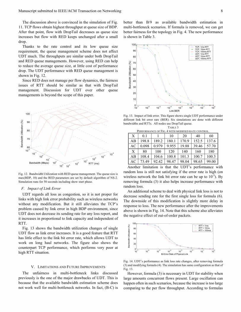
F. Impact of Link Error UDT regards all loss as congestion, so it is not proper for
links with high link error probability such as wireless networks without any modification. But it still alleviates the TCP’s problem caused by link error in high BDP environment, since UDT does not decrease its sending rate for any loss report, and it increases in proportional to link capacity and independent of RTT.
Fig. 13 shows the bandwidth utilization changes of single UDT flow as link error increases. It is a good feature that RTT has little effect to the link bit error rate, which allows UDT to work on long haul networks. The figure also shows the counterpart TCP performance, which performs very poor at high RTT situation.
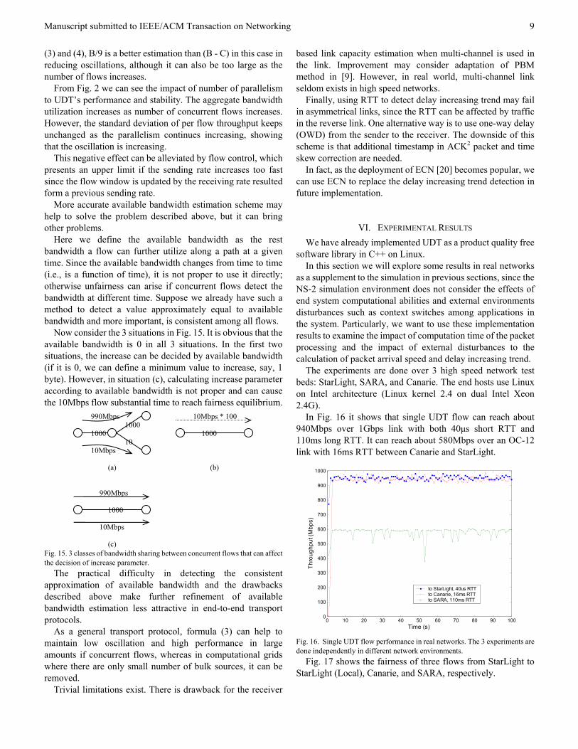
V. LIMITATIONS AND FUTURE IMPROVEMENTS The unfairness in multi-bottleneck links discussed
previously is the one of the major drawbacks of UDT. This is because that the available bandwidth estimation scheme does not work well for multi-bottleneck networks. In fact, (B-C) is
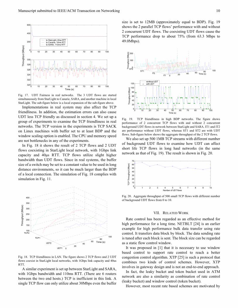
better than B/9 as available bandwidth estimation in multi-bottleneck scenarios. If formula is removed, we can get better fairness for the topology in Fig. 4. The new performance is shown in Table 3.
10-7 10-6 10-5 10-4 10-3 10-2 10-1 1000
10
20
30
40
50
60
70
80
90
100
Link BER
Ban
dwid
th U
tiliz
atio
n (%
)
TCP, 1ms RTTTCP, 10ms RTTTCP, 100ms RTTUDT, 1ms RTTUDT, 10ms RTTUDT, 100ms RTT
Fig. 13. Impact of link error. This figure shows single UDT performance under different link bit error rare (BER). Six simulations are done with different bandwidths and RTTs. All nodes use DropTail queue.
TABLE 3 PERFORMANCE OF FIG. 4 WITH MODIFIED RATE CONTROL.
X 0.1 1 10 20 40 60 AB 198.8 189.2 180.1 170.9 152.5 137.6AC 0.098 0.979 9.955 19.88 39.46 57.70X 80 100 120 140 160 180
AB 108.4 104.6 100.8 101.3 100.7 100.3AC 73.49 92.42 98.47 98.04 98.65 99.00
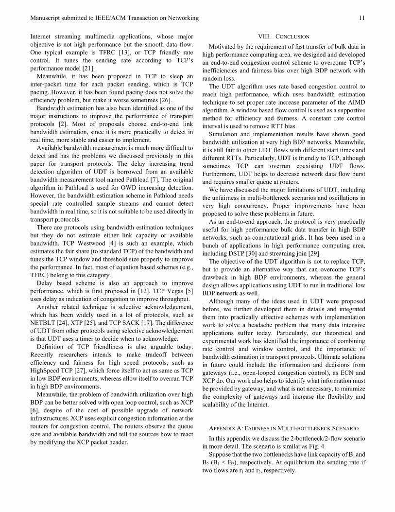
Another limitation is that the UDT’s performance with random loss is still not satisfying if the error rate is high (on wireless network the link bit error rate can be up to 10-3). By removing formula (3) it also helps increase performance with random loss.
An additional scheme to deal with physical link loss is not to decrease sending rate for the first single loss for formula (6). The downside of this modification is slightly more delay in response to loss. The new performance after the improvements above is shown in Fig. 14. Note that this scheme also alleviates the negative effect of out-of-order packets.
10-7
10-6
10-5
10-4
10-3
10-2
10-1
1000
20
40
60
80
100
Bit Error Rate of Physical Link
Ban
dwid
th U
tiliz
atio
n (%
) RTT = 1msRTT = 10msRTT = 100ms
Fig. 14. UDT’s performance as link loss rate changes, after removing formula (3) and modifying formula (4). The simulation has same configuration as that of Fig. 13.
However, formula (3) is necessary in UDT for stability when large amounts concurrent flows present. Large oscillation can happen often in such scenarios, because the increase is too large comparing to the per flow throughput. According to formulas
Manuscript submitted to IEEE/ACM Transaction on Networking
9
(3) and (4), B/9 is a better estimation than (B - C) in this case in reducing oscillations, although it can also be too large as the number of flows increases.
From Fig. 2 we can see the impact of number of parallelism to UDT’s performance and stability. The aggregate bandwidth utilization increases as number of concurrent flows increases. However, the standard deviation of per flow throughput keeps unchanged as the parallelism continues increasing, showing that the oscillation is increasing.
This negative effect can be alleviated by flow control, which presents an upper limit if the sending rate increases too fast since the flow window is updated by the receiving rate resulted form a previous sending rate.
More accurate available bandwidth estimation scheme may help to solve the problem described above, but it can bring other problems.
Here we define the available bandwidth as the rest bandwidth a flow can further utilize along a path at a given time. Since the available bandwidth changes from time to time (i.e., is a function of time), it is not proper to use it directly; otherwise unfairness can arise if concurrent flows detect the bandwidth at different time. Suppose we already have such a method to detect a value approximately equal to available bandwidth and more important, is consistent among all flows.
Now consider the 3 situations in Fig. 15. It is obvious that the available bandwidth is 0 in all 3 situations. In the first two situations, the increase can be decided by available bandwidth (if it is 0, we can define a minimum value to increase, say, 1 byte). However, in situation (c), calculating increase parameter according to available bandwidth is not proper and can cause the 10Mbps flow substantial time to reach fairness equilibrium.
Fig. 15. 3 classes of bandwidth sharing between concurrent flows that can affect the decision of increase parameter.
The practical difficulty in detecting the consistent approximation of available bandwidth and the drawbacks described above make further refinement of available bandwidth estimation less attractive in end-to-end transport protocols.
As a general transport protocol, formula (3) can help to maintain low oscillation and high performance in large amounts if concurrent flows, whereas in computational grids where there are only small number of bulk sources, it can be removed.
Trivial limitations exist. There is drawback for the receiver
based link capacity estimation when multi-channel is used in the link. Improvement may consider adaptation of PBM method in [9]. However, in real world, multi-channel link seldom exists in high speed networks.
Finally, using RTT to detect delay increasing trend may fail in asymmetrical links, since the RTT can be affected by traffic in the reverse link. One alternative way is to use one-way delay (OWD) from the sender to the receiver. The downside of this scheme is that additional timestamp in ACK2 packet and time skew correction are needed.
In fact, as the deployment of ECN [20] becomes popular, we can use ECN to replace the delay increasing trend detection in future implementation.
VI. EXPERIMENTAL RESULTS We have already implemented UDT as a product quality free
software library in C++ on Linux. In this section we will explore some results in real networks
as a supplement to the simulation in previous sections, since the NS-2 simulation environment does not consider the effects of end system computational abilities and external environments disturbances such as context switches among applications in the system. Particularly, we want to use these implementation results to examine the impact of computation time of the packet processing and the impact of external disturbances to the calculation of packet arrival speed and delay increasing trend.
The experiments are done over 3 high speed network test beds: StarLight, SARA, and Canarie. The end hosts use Linux on Intel architecture (Linux kernel 2.4 on dual Intel Xeon 2.4G).
In Fig. 16 it shows that single UDT flow can reach about 940Mbps over 1Gbps link with both 40µs short RTT and 110ms long RTT. It can reach about 580Mbps over an OC-12 link with 16ms RTT between Canarie and StarLight.
0 10 20 30 40 50 60 70 80 90 1000
100
200
300
400
500
600
700
800
900
1000
Time (s)
Thro
ughp
ut (M
bps)
to StarLight, 40us RTTto Canarie, 16ms RTTto SARA, 110ms RTT
Fig. 16. Single UDT flow performance in real networks. The 3 experiments are done independently in different network environments.
Fig. 17 shows the fairness of three flows from StarLight to StarLight (Local), Canarie, and SARA, respectively.
10Mbps
10Mbps * 100
10Mbps
990Mbps
990Mbps
1000 1000
1000
1000
10
(a) (b)
(c)
Manuscript submitted to IEEE/ACM Transaction on Networking
10
0 10 20 30 40 50 60 70 80 90 1000
200
400
600
0 10 20 30 40 50 60 70 80 90 100320
322
324
326
328
330
Time (s)
Thro
ughp
ut (M
bps)
to StarLight, 40us RTTto Canarie, 16ms RTTto SARA, 110ms RTT
Fig. 17. UDT Fairness in real networks. The 3 UDT flows are started simultaneously from StarLight to Canarie, SARA, and another machine in local StarLight. The sub-figure below is a local expansion of the sub-figure above.
Implementations in real system may also affect the TCP friendliness. In addition, the estimation errors can also cause UDT less TCP friendly as discussed in section 4. We set up a group of experiments to examine the TCP friendliness in real networks. The TCP version in the experiments is TCP SACK on Linux machines with buffer set to at least BDP and the window scaling option is enabled. The CPU and memory speed are not bottlenecks in any of the experiments.
In Fig. 18 it shows the result of 2 TCP flows and 2 UDT flows coexisting in StarLight local network, with 1Gbps link capacity and 40µs RTT. TCP flows utilize slight higher bandwidth than UDT flows. Since in real systems, the buffer size of a switch may be set to a constant value to be used in long distance environments, so it can be much larger than the BDP of a local connection. The simulation of Fig. 18 complies with simulation in Fig. 11.
020
4060
80100
UDT1
UDT2
TCP1
TCP2100
150
200
250
300
350
400
Time (s)
Thro
ughp
ut (M
bps)
Fig. 18. TCP friendliness in LAN. The figure shows 2 TCP flows and 2 UDT flows coexist in StarLight local networks, with 1Gbps link capacity and 40us RTT.
A similar experiment is set up between StarLight and SARA, with 1Gbps bandwidth and 110ms RTT. (There are 6 routers between the two end hosts.) TCP is inefficient in this link. A single TCP flow can only utilize about 30Mbps even the buffer
size is set to 12MB (approximately equal to BDP). Fig. 19 shows the 2 parallel TCP flows’ performance with and without 2 concurrent UDT flows. The coexisting UDT flows cause the TCP performance drop to about 75% (from 63.3 Mbps to 49.0Mbps).
0 20 40 60 80 100
IT1IT2
ST1ST2
0
100
200
Time (s)
Thro
ughp
ut (M
bps)
0 10 20 30 40 50 60 70 80 90 1000
20
40
60
80
100
120
Time (s)
Thro
ughp
ut (M
bps)
winthout UDTwith UDT
Fig. 19. TCP friendliness in high BDP networks. The figure shows performance of 2 concurrent TCP flows with and without 2 concurrent background UDT flows in network between StarLight and SARA. IT1 and IT2 are performance without UDT flows, whereas ST1 and ST2 are with UDT flows. Sub-figure below shows the aggregate throughput of the 2 TCP flows.
We also set up 500 1MB TCP streams with different number of background UDT flows to examine how UDT can affect short life TCP flows in long haul networks (in the same network as that of Fig. 19). The result is shown in Fig. 20.
0 1 2 3 4 5 6 7 8 9 100
10
20
30
40
50
60
70
Number of UDT flows
TCP
Thr
ough
put (
Mbp
s)
Fig. 20. Aggregate throughput of 500 small TCP flows with different number of background UDT flows from 0 to 10.
VII. RELATED WORK Rate control has been regarded as an effective method for
high performance for a long time. NETBLT [24] is an earlier example for high performance bulk data transfer using rate control. It transfers data block by block. The data sending rate is tuned after each block is sent. The block size can be regarded as a static flow control window.
It was proposed in [1] that it is necessary to use window based control to support rate control to reach a better congestion control algorithm. XTP [25] is such a protocol that combines two kinds of control schemes. However, XTP involves in gateway design and is not an end-to-end approach.
In fact, the leaky bucket and token bucket used in ATM network are also a similarity as combination of rate control (leaky bucket) and window control (token bucket).
However, most recent rate based schemes are motivated by
Manuscript submitted to IEEE/ACM Transaction on Networking
11
Internet streaming multimedia applications, whose major objective is not high performance but the smooth data flow. One typical example is TFRC [13], or TCP friendly rate control. It tunes the sending rate according to TCP’s performance model [21].
Meanwhile, it has been proposed in TCP to sleep an inter-packet time for each packet sending, which is TCP pacing. However, it has been found pacing does not solve the efficiency problem, but make it worse sometimes [26].
Bandwidth estimation has also been identified as one of the major instructions to improve the performance of transport protocols [2]. Most of proposals choose end-to-end link bandwidth estimation, since it is more practically to detect in real time, more stable and easier to implement.
Available bandwidth measurement is much more difficult to detect and has the problems we discussed previously in this paper for transport protocols. The delay increasing trend detection algorithm of UDT is borrowed from an available bandwidth measurement tool named Pathload [7]. The original algorithm in Pathload is used for OWD increasing detection. However, the bandwidth estimation scheme in Pathload needs special rate controlled sample streams and cannot detect bandwidth in real time, so it is not suitable to be used directly in transport protocols.
There are protocols using bandwidth estimation techniques but they do not estimate either link capacity or available bandwidth. TCP Westwood [4] is such an example, which estimates the fair share (to standard TCP) of the bandwidth and tunes the TCP window and threshold size properly to improve the performance. In fact, most of equation based schemes (e.g., TFRC) belong to this category.
Delay based scheme is also an approach to improve performance, which is first proposed in [12]. TCP Vegas [5] uses delay as indication of congestion to improve throughput.
Another related technique is selective acknowledgement, which has been widely used in a lot of protocols, such as NETBLT [24], XTP [25], and TCP SACK [17]. The difference of UDT from other protocols using selective acknowledgement is that UDT uses a timer to decide when to acknowledge.
Definition of TCP friendliness is also arguable today. Recently researchers intends to make tradeoff between efficiency and fairness for high speed protocols, such as HighSpeed TCP [27], which force itself to act as same as TCP in low BDP environments, whereas allow itself to overrun TCP in high BDP environments.
Meanwhile, the problem of bandwidth utilization over high BDP can be better solved with open loop control, such as XCP [6], despite of the cost of possible upgrade of network infrastructures. XCP uses explicit congestion information at the routers for congestion control. The routers observe the queue size and available bandwidth and tell the sources how to react by modifying the XCP packet header.
VIII. CONCLUSION Motivated by the requirement of fast transfer of bulk data in
high performance computing area, we designed and developed an end-to-end congestion control scheme to overcome TCP’s inefficiencies and fairness bias over high BDP network with random loss.
The UDT algorithm uses rate based congestion control to reach high performance, which uses bandwidth estimation technique to set proper rate increase parameter of the AIMD algorithm. A window based flow control is used as a supportive method for efficiency and fairness. A constant rate control interval is used to remove RTT bias.
Simulation and implementation results have shown good bandwidth utilization at very high BDP networks. Meanwhile, it is still fair to other UDT flows with different start times and different RTTs. Particularly, UDT is friendly to TCP, although sometimes TCP can overrun coexisting UDT flows. Furthermore, UDT helps to decrease network data flow burst and requires smaller queue at routers.
We have discussed the major limitations of UDT, including the unfairness in multi-bottleneck scenarios and oscillations in very high concurrency. Proper improvements have been proposed to solve these problems in future.
As an end-to-end approach, the protocol is very practically useful for high performance bulk data transfer in high BDP networks, such as computational grids. It has been used in a bunch of applications in high performance computing area, including DSTP [30] and streaming join [29].
The objective of the UDT algorithm is not to replace TCP, but to provide an alternative way that can overcome TCP’s drawback in high BDP environments, whereas the general design allows applications using UDT to run in traditional low BDP network as well.
Although many of the ideas used in UDT were proposed before, we further developed them in details and integrated them into practically effective schemes with implementation work to solve a headache problem that many data intensive applications suffer today. Particularly, our theoretical and experimental work has identified the importance of combining rate control and window control, and the importance of bandwidth estimation in transport protocols. Ultimate solutions in future could include the information and decisions from gateways (i.e., open-looped congestion control), as ECN and XCP do. Our work also helps to identify what information must be provided by gateway, and what is not necessary, to minimize the complexity of gateways and increase the flexibility and scalability of the Internet.
APPENDIX A: FAIRNESS IN MULTI-BOTTLENECK SCENARIO In this appendix we discuss the 2-bottleneck/2-flow scenario
in more detail. The scenario is similar as Fig. 4. Suppose that the two bottlenecks have link capacity of B1 and
B2 (B1 < B2), respectively. At equilibrium the sending rate if two flows are r1 and r2, respectively.
Manuscript submitted to IEEE/ACM Transaction on Networking
12
On one hand, according to (4), r1 will keep increasing until:
2211 10 rBrB y −≤<− (8) where y is an integer. On the other hand, since B1 < B2, we have:
2/21 Br ≤ (9) At equilibrium phase, UDT can approximately utilize all
bandwidth according to the efficiency analysis, therefore:
221 Brr ≈+ (10) From (8), (9), and (10) we can reach:
2/2/ 211 BrB << (11) According to max-min fairness principle, the fair share of r1
should be either B1 (if B1 < B2/2) or B2/2 (otherwise). So in the worst case r1 can still reach half of the fair share.
In more detail, suppose: 1
1 1010 +<≤ aa B (12) where a is an integer. According to (8), (11), and (12),
)2/),10,10min(max( 211 BBr aa −≈ (13) So the worst case happens when B1 < B2/2 and B1 = 2*10a. The analysis above assumes that the effects of formula (3)
and the smaller increases after that the available bandwidth of r1 satisfies (8). In fact formula (3) can bring some negative effects to fairness as is shown in Table 1 and 3. Meanwhile, the smaller increases can increase r1 up to 11%.
APPENDIX B: IMPLEMENTATION ISSUES Implementation is critical for high performance data transfer
protocols. Some algorithms works well in theory and simulation but may have poor performance if the implementation is not well designed. In this appendix we describe several critical part of UDT algorithm that should be pay more attention in implementations.
One of the most common problems is that the generation of control information and application data reading at the receiver side can take substantial time, comparing to the high packet arriving rate. A poor implementation may cause frequent packet drop and even packet loss avalanche (loss processing causes more loss). For example, since UDT uses explicit loss feedback, the receiver maintains a loss list to record the loss information. Access to the loss list may need so long a time that the arriving packets overflow the protocol buffer.
To handle this kind of problem, it is necessary to distribute the processing evenly into small pieces even if this leads to higher aggregate processing time, if the processing cannot be made small enough to avoid the problem.
For example, we use a special data structure for loss information such that all operations of insert, delete, and update take similar small time, whereas by using a simple array or linked list structure the insert and delete operations will need to scan and/or move data, which takes substantial time during high congestion due to large amounts of lost packets.
Memory copy is another problem that can cause similar
problem. However, this kind of problem has been thoroughly addressed in a lot of work, such as [23].
Finally, special notice may arise on the high precision timer needed for rate control. Currently such a timer is not available on many general-purpose operating systems. For data transfer at gigabits per second, the timing precision should be at least microsecond level, and it is better at CPU frequency level. A simple implementation can use busy loop to query CPU clock cycles. There is also hardware support to use interrupt on some platforms, such as APIC [32] on Intel architecture.
Many implementations of rate based protocol use an additional variable of burst size, to control the number of packets that can be sent out continuously without inter-packet delay and then sleep for a longer aggregate interval. This method is used to avoid the high precision timing problem as long as the aggregate sleeping time is long enough. However, in high speed networks, the number of packets can be sent in the minimum sleep interval of the system can be very large and makes the rate control meaningless.
The other timers to trigger the feedback interval, rate adjustment, and expiration event do not need high precision, so they can be implemented by self-clocking, i.e., querying the system time after each sending or time bounded receiving event.
The implementation source code and simulation scripts of UDT are available online [31].
REFERENCES [1] S. Keshav, A Control-Theoretic Approach to Flow Control, Proceedings
of ACM SIGCOMM'91, Zurich, Switzerland, pp. 3-15, September 1991. [2] Mark Allman and Vern Paxson. On Estimating End-to-End Network Path
Properties. In ACM SIGCOMM, September 1999. [3] D. Chiu and R. Jain, Analysis of the Increase/Decrease Algorithms for
Congestion Avoidance in Computer Networks, Journal of Computer Networks and ISDN, Vol. 17, No. 1, June 1989, pp. 1-14.
[4] M. Gerla, M. Y. Sanadidi, R. Wang, A. Zanella, C. Casetti, and S. Mascolo, TCP Westwood: Congestion Window Control Using Bandwidth Estimation, In Proceedings of IEEE Globecom 2001, Volume: 3, pp 1698-1702.
[5] L. Brakmo and L. Peterson, TCP Vegas: End-to-End Congestion Avoidance on a Global Internet, IEEE Journal on Selected Areas in Communication, Vol 13, No. 8 (October 1995) pages 1465-1480.
[6] D. Katabi, M. Hardley, and C. Rohrs, Internet Congestion Control for Future High Bandwidth-Delay Product Environments, ACM SIGCOMM 2002.
[7] M. Jain and C. Dovrolis, Pathload: A Measurement Tool for End-to-End Available Bandwidth, Proceedings of Passive and Active Measurements (PAM) 2002 workshop, pages 14-25, Fort Collins, CO.
[8] V. Paxson, End-to-End Internet Packet Dynamics, IEEE/ACM Transactions on Networking, Vol.7, No.3, pp. 277-292, June 1999.
[9] V. Paxson, Measurements and Analysis of End-to-End Internet Dynamics. PhD thesis, Computer Science Division, University of California, Berkeley, April 1997.
[10] Foster, C. Kesselman, S. Tuecke, The Anatomy of the Grid: Enabling Scalable Virtual Organizations. International J. Supercomputer Applications, 15(3), 2001.
[11] M. Jain and C. Dovrolis, End-to-End Available Bandwidth: Measurement methodology, Dynamics, and Relation with TCP Throughput, in Proceedings of ACM SIGCOMM, August 2002.
[12] R. Jain, A Delay Based Approach for Congestion Avoidance in Interconnected Heterogeneous Computer Networks, Computer Communications Review, ACM SIGCOMM, October 1989, pp. 56-71.
Manuscript submitted to IEEE/ACM Transaction on Networking
13
[13] Sally Floyd, Mark Handley, Jitendra Padhye, and Joerg Widmer, Equation-Based Congestion Control for Unicast Applications, ACM SIGCOMM 2000, Stockholm, Aug 2000.
[14] M. Allman, V. Paxson, W. Stevens, TCP Congestion Control, RFC 2581, April 1999.
[15] S. Floyd and V. Jacobson. On traffic phase effects in packet-switched gateways. Internetworking: Research and Experience, 3:115-156, 1992.
[16] Floyd, S., and Fall, K. Promoting the Use of End-to-End Congestion Control in the Internet. IEEE/ACM Transactions on Networking, August 1999.
[17] Mathis, M., Mahdavi, J., Floyd, S., and Romanow, A., TCP Selective Acknowledgement Options. RFC 2018, April 1996.
[18] P. Varaiya and J. Walrand, High-Performance Communication Networks. Morgan Kaufmann, San Francisco, October 1996.
[19] T. Lakshman and U. Madhow. The Performance of TCP/IP for Networks with High Bandwidth-Delay Products and Random Loss. IEEE/ACM Transactions on Networking, pages 336--350, June 1997.
[20] Ramakrishnan, K.K., Floyd, S., and Black, D. The Addition of Explicit Congestion Notification (ECN) to IP. RFC 3168, Proposed Standard, September 2001.
[21] J. Padhye, V. Firoiu, D. Towsley, and J. Kurose. Modeling TCP throughput: a simple model and its empirical validation. ACMSIGCOMM, September 1998.
[22] Feng, W., and Tinnakornsrisuphap, P., The Failure of TCP in High-Performance Computational Grids, Supercomputing 2000.
[23] J. Chu, Zero-copy TCP in Solaris. In proceedings of the 1996 Usenix Technical Conference, pages 253-264, San Diego, CA, USA, Jan. 1996.
[24] D. Clark, M. Lambert, and L. Zhang, NETBLT: A high throughput transport protocol, SIGCOMM '87, (Stowe, VT).
[25] Strayer, T., Dempsey, B., and Weaver A., XTP – the Xpress Transfer Protocol. Addison-Wesley Publishing Company, 1992.
[26] A. Aggarwal, S. Savage, and T. Anderson, Understanding the Performance of TCP Pacing. Proc. of IEEE Infocom 2000, pp. 1157-1165
[27] HighSpeed TCP. http://www.icir.org/floyd/hstcp.html. [28] Hacker, T., Athey, B., and Noble, B. The End-to-End Performance Effects
of Parallel TCP Sockets on a Lossy Wide-Area Network, Proceedings of the 16th IEEE-CS/ACM International Parallel and Distributed Processing Symposium (IPDPS) 2001.
[29] M. Mazzucco, A. Ananthanarayan, R. Grossman, J. Levera, and G. Bhagavantha Rao, Merging Multiple Data Streams on Common Keys over High Performance Networks, Proc. of SuperComputing 2002.
[30] R. Grossman and M. Mazzucco, DataSpace - A Web Infrastructure for the Exploratory Analysis and Mining of Data, IEEE Computing in Science and Engineering, July/August, 2002, pp. 44-51.
[31] UDT source code. http://cvs.sourceforge.net/cgi-bin/viewcvs.cgi/dataspace/UDT/.
[32] Intel 82093AA I/O Advanced Programmable Interrupt Controller (I/O APIC), available at http://www.intel.com/design/chipsets/datashts/290566.htm.
[33] NS-2, http://www.isi.edu/nsnam/ns/. [34] Internet2 NetFlow, http://netflow.internet2.edu/weekly/. [35] Spring IPMON Packet Trace Analysis,
http://ipmon.sprint.com/packstat/packetoverview.php.