Embed Size (px)
Citation preview
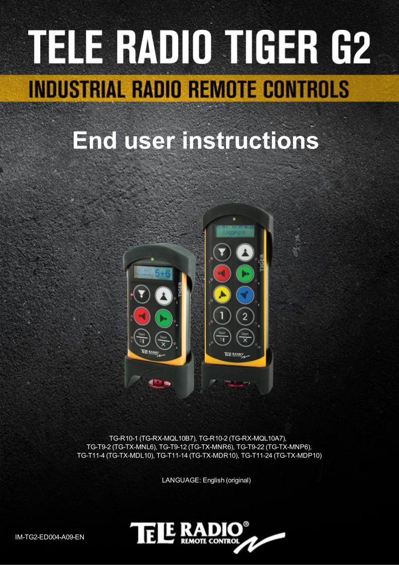
TG-R10-1 (TG-RX-MQL10B7), TG-R10-2 (TG-RX-MQL10A7), TG-T9-2 (TG-TX-MNL6), TG-T9-12 (TG-TX-MNR6), TG-T9-22 (TG-TX-MNP6),
TG-T11-4 (TG-TX-MDL10), TG-T11-14 (TG-TX-MDR10), TG-T11-24 (TG-TX-MDP10)
LANGUAGE: English (original)
IM-TG2-ED004-A09-EN
End user instructions
CONTENTS
Chapter 1: CUSTOMER INFORMATION 3Chapter 2: END USER INSTRUCTIONS 5
Product measurements 8Start the transmitter in operating mode 9Start the transmitter in operating mode with PIN codes 9Start the transmitter in operating mode using RFID 10Turn the transmitter off 11Login/logout 11Replace 12Automatic shutdown 13Frequencies & channels 13RoHS and WEEE 18Guarantee, service, repairs and maintenance 19
Chapter 3: EC DECLARATION OF CONFORMITY 20
- 2 -
Chapter 1: CUSTOMER INFORMATION
CHAPTER 1: CUSTOMER INFORMATION
THANK YOU FOR PURCHASING A TELE RADIO AB PRODUCT READ ALL INSTRUCTIONS AND WARNINGS CAREFULLY BEFORE USING THE PRODUCTS. These instructions are published by Tele Radio AB without any guarantee. The instructions may be removed or revised by Tele Radio AB at any time and without further notice. Corrections and additions will be added to the latest version of the instruction. IMPORTANT! These instructions are directed towards end users. They can be printed and handed to end users. The installation instructions that contain information on the installation and configuration of the radio remote control unit on the machine are not intended to be passed on to the end user. Only such information may be passed on to the end user that is needed to operate the machine correctly by radio remote control. Tele Radio AB products are covered by a guarantee/ warranty against material, construction or manufacturing faults. During the guarantee/ warranty period, Tele Radio AB may replace the product or faulty parts with new. Work under guarantee/ warranty must be carried out by Tele Radio AB or by an authorized service center specified by Tele Radio AB. Contact your Tele Radio AB representative if you need support or service. ©Tele Radio AB, 2013Datavägen 21SE-436 36 ASKIMSWEDENTel: +46-31-748 54 60Fax: +46-31-68 54 64www.tele-radio.com
END USER WARNINGS & RESTRICTIONS
l Only qualified personnel should perform the installation and settings for the system. l Do not open the receiver encapsulation unless you are qualified. l Read and follow the end user instructions carefully. l You must have reached the certified age of your country to operate the equipment. l It is strictly prohibited to operate the equipment under the influence of drugs, alcohol and
medicines. l Keep the products in a dry, clean place. l Keep contacts and antennas clean. l Wipe off dust using a slightly damp, clean cloth. l Never use cleaning solutions or high-pressure water. l Check the transmitter encapsulation and foil for damages every day. If you use the
transmitter although the encapsulation or foil is damaged, moisture can cause serious damage to the electronics. The guarantee/ warranty does not cover the cost of repairing such damages caused by moisture. Contact your representative immediately if you find any damage to the transmitter, or if you require service for or other assistance with your transmitter.
- 3 -
Chapter 1: CUSTOMER INFORMATION
APPLICATION AREA FOR THE TIGER SYSTEM The Tele Radio AB Tiger remote control systems are aimed for remote controlling of lifting or mobile equipment where a high safety level is required.
AUTHORIZATION BY PIN CODE To prevent from unauthorized users being able to start the transmitter and control the receiver, you can enable PIN codes for start-up protection. 1-10 PIN codes can be stored in the TG-TX-MNL6, TG-TX-MNR6, TG-TX-MNP6 and TG-TX-MDL10, TG-TX-MDR10, TG-TX-MDP10 transmitters.
STOP FUNCTION The transmitters have a stop button that controls the 2 stop relays in the receiver. 2 safety microcontrollers are supervising and controlling the stop relays. A valid signal must be provided from both microcontrollers to activate the stop relays.
- 4 -
Chapter 2: END USER INSTRUCTIONS
CHAPTER 2: END USER INSTRUCTIONS
1
2
3
4
5
7
8
9
10
11
6
6
7
15
10
11
8
9
13
1
2
3
4
5
12
14
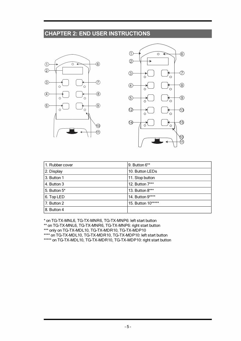
1. Rubber cover 9. Button 6**
2. Display 10. Button LEDs
3. Button 1 11. Stop button
4. Button 3 12. Button 7***
5. Button 5* 13. Button 8***
6. Top LED 14. Button 9****
7. Button 2 15. Button 10*****
8. Button 4 * on TG-TX-MNL6, TG-TX-MNR6, TG-TX-MNP6: left start button** on TG-TX-MNL6, TG-TX-MNR6, TG-TX-MNP6: right start button*** only on TG-TX-MDL10, TG-TX-MDR10, TG-TX-MDP10**** on TG-TX-MDL10, TG-TX-MDR10, TG-TX-MDP10: left start button***** on TG-TX-MDL10, TG-TX-MDR10, TG-TX-MDP10: right start button
- 5 -
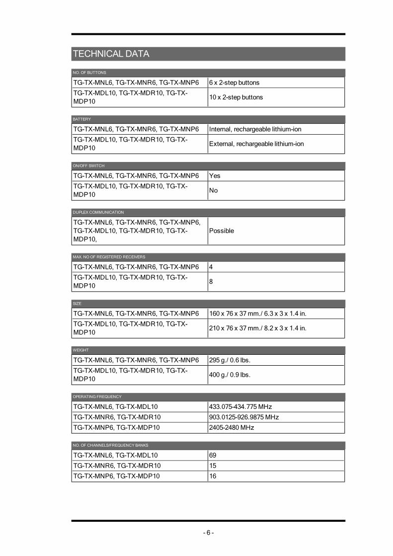
TECHNICAL DATA NO. OF BUTTONS
TG-TX-MNL6, TG-TX-MNR6, TG-TX-MNP6 6 x 2-step buttons
TG-TX-MDL10, TG-TX-MDR10, TG-TX-MDP10
10 x 2-step buttons
BATTERY
TG-TX-MNL6, TG-TX-MNR6, TG-TX-MNP6 Internal, rechargeable lithium-ion
TG-TX-MDL10, TG-TX-MDR10, TG-TX-MDP10
External, rechargeable lithium-ion
ON/OFF SWITCH
TG-TX-MNL6, TG-TX-MNR6, TG-TX-MNP6 Yes
TG-TX-MDL10, TG-TX-MDR10, TG-TX-MDP10
No
DUPLEX COMMUNICATION
TG-TX-MNL6, TG-TX-MNR6, TG-TX-MNP6, TG-TX-MDL10, TG-TX-MDR10, TG-TX-MDP10,
Possible
MAX. NO OF REGISTERED RECEIVERS
TG-TX-MNL6, TG-TX-MNR6, TG-TX-MNP6 4
TG-TX-MDL10, TG-TX-MDR10, TG-TX-MDP10
8
SIZE
TG-TX-MNL6, TG-TX-MNR6, TG-TX-MNP6 160 x 76 x 37 mm./ 6.3 x 3 x 1.4 in.
TG-TX-MDL10, TG-TX-MDR10, TG-TX-MDP10
210 x 76 x 37 mm./ 8.2 x 3 x 1.4 in.
WEIGHT
TG-TX-MNL6, TG-TX-MNR6, TG-TX-MNP6 295 g./ 0.6 lbs.
TG-TX-MDL10, TG-TX-MDR10, TG-TX-MDP10
400 g./ 0.9 lbs.
OPERATING FREQUENCY
TG-TX-MNL6, TG-TX-MDL10 433.075-434.775 MHz
TG-TX-MNR6, TG-TX-MDR10 903.0125-926.9875 MHz
TG-TX-MNP6, TG-TX-MDP10 2405-2480 MHz NO. OF CHANNELS/FREQUENCY BANKS
TG-TX-MNL6, TG-TX-MDL10 69
TG-TX-MNR6, TG-TX-MDR10 15
TG-TX-MNP6, TG-TX-MDP10 16
- 6 -
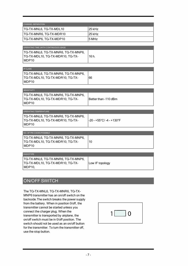
CHANNEL SEPARATION
TG-TX-MNL6, TG-TX-MDL10 25 kHz
TG-TX-MNR6, TG-TX-MDR10 25 kHz
TG-TX-MNP6, TG-TX-MDP10 5 MHz OPERATING TIME (WITH CONTINUOUS USAGE
TG-TX-MNL6, TG-TX-MNR6, TG-TX-MNP6, TG-TX-MDL10, TG-TX-MDR10, TG-TX-MDP10
16 h.
IP CLASS
TG-TX-MNL6, TG-TX-MNR6, TG-TX-MNP6, TG-TX-MDL10, TG-TX-MDR10, TG-TX-MDP10
66
SENSITIVITY
TG-TX-MNL6, TG-TX-MNR6, TG-TX-MNP6, TG-TX-MDL10, TG-TX-MDR10, TG-TX-MDP10
Better than -110 dBm
OPERATING TEMPERATURE
TG-TX-MNL6, TG-TX-MNR6, TG-TX-MNP6, TG-TX-MDL10, TG-TX-MDR10, TG-TX-MDP10
-20 - +55°C/ -4 - +130°F
NO. OF PIN CODES POSSIBLE
TG-TX-MNL6, TG-TX-MNR6, TG-TX-MNP6, TG-TX-MDL10, TG-TX-MDR10, TG-TX-MDP10
10
RADIOTYPE
TG-TX-MNL6, TG-TX-MNR6, TG-TX-MNP6, TG-TX-MDL10, TG-TX-MDR10, TG-TX-MDP10,
Low IF topology
ON/OFF SWITCH The TG-TX-MNL6, TG-TX-MNR6, TG-TX-MNP6 transmitter has an on/off switch on the backside.The switch breaks the power supply from the battery. When in position 0/off, the transmitter cannot be started unless you connect the charger plug. When the transmitter is transported by airplane, the on/off switch must be in 0/off position. The switch should not be used as an on/off button for the transmitter. To turn the transmitter off, use the stop button.
- 7 -

PRODUCT MEASUREMENTS TG-TX-MNL6, TG-TX-MNR6, TG-TX-MNP6
160
mm
(6.3
1in
)
76 mm (3 in) 46 mm (1.8 in)
TG-TX-MDL10,TG-TX-MDR10, TG-TX-MDP10
79 mm (3.1 in)
208
mm
(8.2
in)
41 mm (1.6 in)
51 mm (2 in)
- 8 -
START THE TRANSMITTER IN OPERATING MODE 1. Make sure that the stop button is pressed 2. Pull out the stop button.The top LED lights (green when the battery capacity is good, red when the battery capacity is poor). 3. If PIN codes are used for authorization: Go to the next section. 4. WITHIN 3 MINUTES FROM PULLING OUT THE STOP BUTTON: Press a button to select the receiver(s) that you want to operate.The receiver(s) that was selected in the last session will be automatically selected, which is indicated by the corresponding LED(s) that light red. If no receiver(s) has been selected, the LEDs for all available receivers will flash red. If a receiver is selected, the LEDs next to the left and the right start buttons flash red. If no receiver(s) are selected, only the LED next to the right start button flashes red. 5. Press both start buttons at the same time.The buzzer beeps. 6. Release the start buttons.The buzzer stops beeping. The top LED flashes (green when the battery capacity is good, red when the battery capacity is poor). 7. When radio communication has been established, the top LED lights (green when the battery capacity is good, red when the battery capacity is poor). If radio communication is not established within 25 seconds, the transmitter turns off.
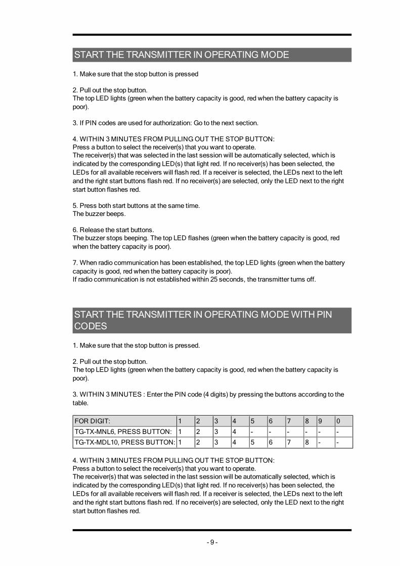
START THE TRANSMITTER IN OPERATING MODE WITH PIN CODES 1. Make sure that the stop button is pressed. 2. Pull out the stop button.The top LED lights (green when the battery capacity is good, red when the battery capacity is poor). 3. WITHIN 3 MINUTES : Enter the PIN code (4 digits) by pressing the buttons according to the table. FOR DIGIT: 1 2 3 4 5 6 7 8 9 0
TG-TX-MNL6, PRESS BUTTON: 1 2 3 4 - - - - - -
TG-TX-MDL10, PRESS BUTTON: 1 2 3 4 5 6 7 8 - - 4. WITHIN 3 MINUTES FROM PULLING OUT THE STOP BUTTON: Press a button to select the receiver(s) that you want to operate.The receiver(s) that was selected in the last session will be automatically selected, which is indicated by the corresponding LED(s) that light red. If no receiver(s) has been selected, the LEDs for all available receivers will flash red. If a receiver is selected, the LEDs next to the left and the right start buttons flash red. If no receiver(s) are selected, only the LED next to the right start button flashes red.
- 9 -
5. Press both start buttons at the same time.The buzzer beeps. 6. Release the start buttons.The buzzer stops beeping. The top LED flashes (green when the battery capacity is good, red when the battery capacity is poor). 7. When radio communication has been established, the top LED lights (green when the battery capacity is good, red when the battery capacity is poor). If radio communication is not established within 25 seconds, the transmitter turns off.
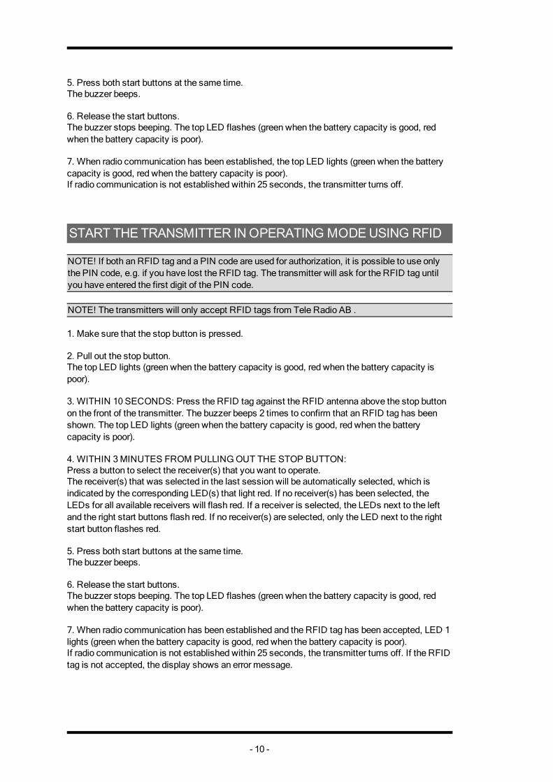
START THE TRANSMITTER IN OPERATING MODE USING RFID NOTE! If both an RFID tag and a PIN code are used for authorization, it is possible to use only the PIN code, e.g. if you have lost the RFID tag. The transmitter will ask for the RFID tag until you have entered the first digit of the PIN code. NOTE! The transmitters will only accept RFID tags from Tele Radio AB . 1. Make sure that the stop button is pressed. 2. Pull out the stop button.The top LED lights (green when the battery capacity is good, red when the battery capacity is poor). 3. WITHIN 10 SECONDS: Press the RFID tag against the RFID antenna above the stop button on the front of the transmitter. The buzzer beeps 2 times to confirm that an RFID tag has been shown. The top LED lights (green when the battery capacity is good, red when the battery capacity is poor). 4. WITHIN 3 MINUTES FROM PULLING OUT THE STOP BUTTON: Press a button to select the receiver(s) that you want to operate.The receiver(s) that was selected in the last session will be automatically selected, which is indicated by the corresponding LED(s) that light red. If no receiver(s) has been selected, the LEDs for all available receivers will flash red. If a receiver is selected, the LEDs next to the left and the right start buttons flash red. If no receiver(s) are selected, only the LED next to the right start button flashes red. 5. Press both start buttons at the same time.The buzzer beeps. 6. Release the start buttons.The buzzer stops beeping. The top LED flashes (green when the battery capacity is good, red when the battery capacity is poor). 7. When radio communication has been established and the RFID tag has been accepted, LED 1 lights (green when the battery capacity is good, red when the battery capacity is poor). If radio communication is not established within 25 seconds, the transmitter turns off. If the RFID tag is not accepted, the display shows an error message.
- 10 -
TURN THE TRANSMITTER OFF 1. Press the stop button.The transmitter turns off. All relays deactivate.
LOGIN/LOGOUT
Quick logout NOTE! When the transmitter has established radio communication with one or more receivers, you can make a Quick logout from those receivers. Note that the Quick logout will log the transmitter out from all receivers that are participating in the session. NOTE! If you need to log out a transmitter that is lost or damaged, it is possible to log out from the receiver. We do not recommend this way of logging out. Contact your representative for assistance. NOTE! To be able to control a receiver, the transmitter must be registered in the receiver, and logged in to the receiver. If another transmitter is already logged in to the receiver, it has to be logged out before any other transmitter can be logged in. If no transmitter is logged in to a receiver, a registered transmitter will automatically log in when sending radio signals to the receiver. The transmitter will stay logged in until it is manually logged out. More than one transmitter can be registered in the receiver, but only one transmitter can be logged in at a time. 1. Make sure that the transmitter is started in operating mode. NOTE! The transmitter must have established a radio session with one or more receivers. 2. Press the left start button. Keep pressed. 3. Press the stop button. 4. Release the left start button.The top LED lights red.The display shows [Logging out].The transmitter turns off after logging out.
- 11 -
REPLACE You can replace a registered transmitter with another transmitter without having access to the receiver. IMPORTANT! If the transmitter that needs to be replaced is registered in more than one receiver, it will only be replaced in one receiver at a time. If you want to replace a transmitter in more than one receiver, you need to perform a replacement for each receiver. IMPORTANT! Do not perform this when the receiver is in a session with another transmitter. The radio communication may become disturbed or broken. NOTE! If the transmitter already have receivers registered, we recommend that you erase all receivers from the transmitter before starting the replacement. The receiver will automatically be stored in the same position as it was stored in the old transmitter. If this position is not available, the replacement will not take place.
Replace a transmitter with a new transmitter 1. Make sure that the stop button is pressed. 2. Pull out the stop button.The top LED lights (green when the battery capacity is good, red when the battery capacity is poor). 3. Press the right start button. Keep pressed. 4. Press the stop button. 5. Release the right start button.The top LED flashes (green when the battery capacity is good, red when the battery capacity is poor) when in menu mode. 6. Go to [Replace]. Select by pressing the left start button. 7. Enter the serial number/ID code for the transmitter that you want to replace by pressing the buttons according to the table below: Press button To
1 count -1
2 count +1
3 go left
4 go right 8.Press the left start button.The display shows [Replacing] while the process is ongoing.If the replacement fails, the display shows [FAILED].The transmitter turns off.If the replacement succeeds, the display shows [OK]. The transmitter turns off.
- 12 -
AUTOMATIC SHUTDOWN Turning on automatic shutdown can save battery capacity by automatically turning the transmitter off when no function has been activated for a set time.
Set the time for automatic shutdown 1. Start the transmitter. 2. Enter menu mode. 3. Go to [Auto Shutdown]. Select by pressing the left start button. 4. Select the time that you want for automatic shutdown: 0-255 minutes. If you want to turn off automatic shutdown, select 0. Confirm by pressing the left start button.
FREQUENCIES & CHANNELS NOTE! If your system is transmitting on the frequency bands 433MHz eller 2.4 GHz, the receiver will automatically detect and switch to the same channel that the transmitter is using. If your system is transmitting the 915 MHz frequency band, you have to switch bank in the receiver by using the PC program Settings manager. Contact your representative for assistance.
Switch channel on the transmitter 1. Make sure that the stop button is pressed. 2. Pull out the stop button.The top LED lights (green when the battery capacity is good, red when the battery capacity is poor). 3. Press the right start button. Keep pressed. 4. Press the stop button. 5. Release the right start button.The top LED flashes (green when the battery capacity is good, red when the battery capacity is poor) when in menu mode. 6. Go to [Channel/Bank]. 7. Go to the frequency table and select a channel. Confirm by pressing the left start button.
- 13 -
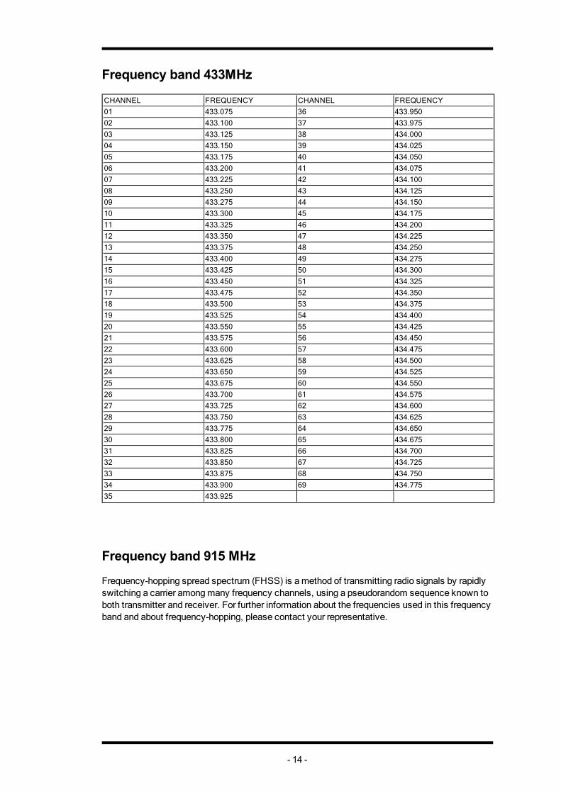
Frequency band 433MHz CHANNEL FREQUENCY CHANNEL FREQUENCY01 433.075 36 433.95002 433.100 37 433.97503 433.125 38 434.00004 433.150 39 434.02505 433.175 40 434.05006 433.200 41 434.07507 433.225 42 434.10008 433.250 43 434.12509 433.275 44 434.15010 433.300 45 434.17511 433.325 46 434.20012 433.350 47 434.22513 433.375 48 434.25014 433.400 49 434.27515 433.425 50 434.30016 433.450 51 434.32517 433.475 52 434.35018 433.500 53 434.37519 433.525 54 434.40020 433.550 55 434.42521 433.575 56 434.45022 433.600 57 434.47523 433.625 58 434.50024 433.650 59 434.52525 433.675 60 434.55026 433.700 61 434.57527 433.725 62 434.60028 433.750 63 434.62529 433.775 64 434.65030 433.800 65 434.67531 433.825 66 434.70032 433.850 67 434.72533 433.875 68 434.75034 433.900 69 434.77535 433.925
Frequency band 915 MHz Frequency-hopping spread spectrum (FHSS) is a method of transmitting radio signals by rapidly switching a carrier among many frequency channels, using a pseudorandom sequence known to both transmitter and receiver. For further information about the frequencies used in this frequency band and about frequency-hopping, please contact your representative.
- 14 -
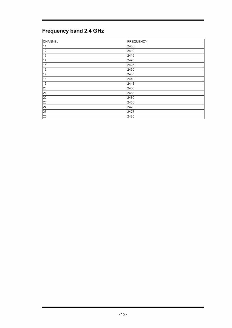
Frequency band 2.4 GHz CHANNEL FREQUENCY11 240512 241013 241514 242015 242516 243017 243518 244019 244520 245021 245522 246023 246524 247025 247526 2480
- 15 -

Transmitter backside
1. Rubber cover 4. CE and product label2. Stop button 5. Battery charger socket3. Clip 6. On/off switch* * only on TG-TX-MNL6, TG-TX-MNR6, TG-TX-MNP6
BATTERY INFORMATION IMPORTANT! Electronics and batteries must be physically separated before disposal. Make sure that electronics or batteries are not thrown in the household waste. IMPORTANT! For transmitters with an on/off switch, the switch must be in on position when charging.
TG-TX-MNL6, TG-TX-MNR6 , TG-TX-MNP6
TG-TX-MDL10, TG-TX-MDR10, TG-TX-MDP10
Battery typeInternal, rechargeable lithium-ion battery
External, rechargeable lithium-ion battery
Operating timeApprox. 16 h. with continuous usage
Approx. 16 h. with continuous usage
ChargeCharger plug in the back of the transmitter
Charger plug in the back of the trans-mitter or in the Tele Radio 5 V DC charger unit
Charging temperature 0- 45°C/ 32-113 °F 0- 45°C/ 32-113 °F
- 16 -
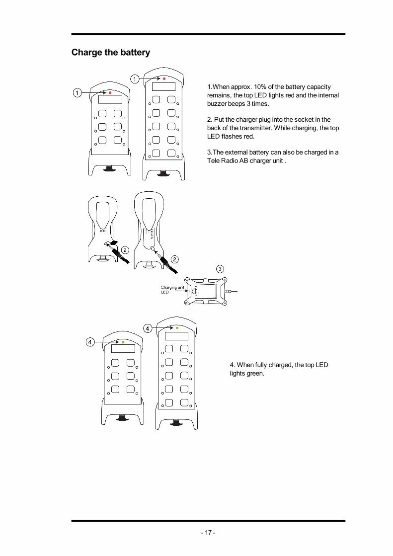
Charge the battery
1.When approx. 10% of the battery capacity remains, the top LED lights red and the internal buzzer beeps 3 times. 2. Put the charger plug into the socket in the back of the transmitter. While charging, the top LED flashes red. 3.The external battery can also be charged in a Tele Radio AB charger unit .
4. When fully charged, the top LED lights green.
- 17 -
NOTE! For lithium-ion batteries, overcharging is not a problem. Lithium-ion batteries do not need to be fully discharged before being recharged. Charging the battery before fully discharged will not cause premature loss of function. Lithium-ion batteries are designed for operating environments from 0ºC to 60ºC/ 32ºF to 140ºF. Note that the environmental temperature and the operating temperature are not necessarily the same. The higher the temperatures, the faster the discharge. When you do not intend to use the transmitter for a longer period of time, we recommend that you remove the battery from the transmitter. The transmitter uses current even when being turned off. Leaving the battery in the transmitter may affect the battery life span. Improper long term storage of lithium-ion batteries can reduce their effective life. New lithium-ion batteries should be stored in a location with ambient temperatures between 20ºC to 38ºC/ 70º to 100ºF at a 40% state of charge or lower. After use, batteries can be stored at higher charge levels. After a longer period of storage, we recommend recharging of batteries prior to being placed back into service or use. Batteries stored in cold environments may need to be stabilized within normal temperature ranges prior to recharging and use. Batteries can be replaced when they are no longer capable of holding 80% of their original capacity. Users should consider how frequently an old battery is recharged compared to when it was new. We recommend that you check with your representative if you need further details.
BATTERY PRECAUTIONS Observe the following general battery warnings:
n As batteries contains flammable substances such as lithium or other organic solvents, they may cause heating, rupture or ignition.
n Risk of explosion if battery is replaced with a battery of an incorrect type. n Do not short circuit, disassemble, deform or heat batteries. n Never try to charge a visibly damaged or frozen battery. n Keep batteries out of reach of small children. Should a child swallow a battery, consult a
physician immediately. n Avoid direct soldering to batteries. n When discarding batteries, insulate the + and - terminals of batteries with insulating/ mask-
ing tape. Do not put multiple batteries in the same plastic bag. n When improperly disposed, lithium batteries may short circuit, causing them to become
hot, burst or ignite. n Store in a cool location. Keep batteries away from direct sunlight, high temperature, and
high humidity. n Do not throw batteries into fire.
ROHS AND WEEE In accordance with Directive 2011/65/EU on restriction of the use of certain hazardous substances in electrical and electronic equipment (RoHS) and Directive 2002/96/EC on waste electrical and electronic equipment (WEEE), Tele Radio AB strives to minimize the use of hazardous materials, promotes reuse and recycling, and reduces emissions to air, soil and water. When a commercially viable alternative is available, Tele Radio AB strives to restrict or eliminate substances and materials that pose an environmental, health or safety risk.
- 18 -
REMOVAL OF INTERNAL BATTERY IMPORTANT! Electronics and batteries must be physically separated before disposal. Make sure that electronics or batteries are not thrown in the household waste. 1. Remove the clip. Remove the rubber cover by hand. Use a screwdriver to unscrew the 2 screws. 2. Use a screwdriver to unscrew the 4 screws. Remove the front encapsulation by hand. Turn thetransmitter around, so that the buttons face up. 3. Use a screwdriver to unscrew the screw in the middle of the transmitter. Lift the circuit board up by hand. 4. The battery pack is placed behind the circuit board. Remove the battery by hand.
GUARANTEE, SERVICE, REPAIRS AND MAINTENANCE The Tele Radio AB products are covered by a guarantee/warranty against material, construction and manufacturing faults. During the guarantee/warranty period, Tele Radio AB may replace the product or faulty parts. Work under guarantee/warranty must be carried out by Tele Radio AB or by an authorized service centre specified by Tele Radio AB. This is not covered by the guarantee/ warranty:
n Faults resulting from normal wear and tear n Parts of a consumable nature n Products that have been subject to unauthorized modifications n Faults resulting from incorrect installation and use n Damp and water damage
Maintenance:
n Repairs and maintenance must be carried out by qualified personnel n Use spare parts from Tele Radio AB only n Contact your representative if you require service or other assistance n Keep the product in a dry, clean place n Keep contacts and antennas clean n Wipe off dust using a slightly damp, clean cloth
IMPORTANT! Never use cleaning solutions or high-pressure water.
- 19 -
Chapter 3: EC DECLARATION OF CONFORMITY
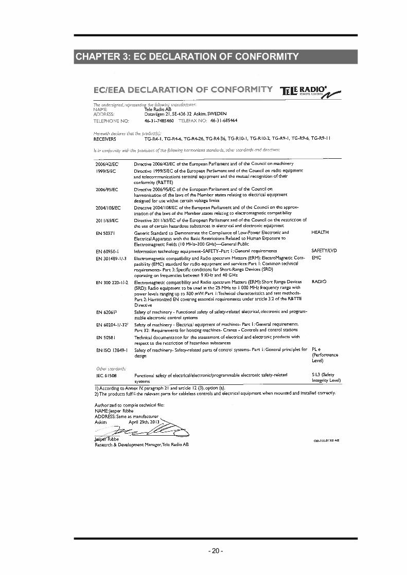
CHAPTER 3: EC DECLARATION OF CONFORMITY
- 20 -
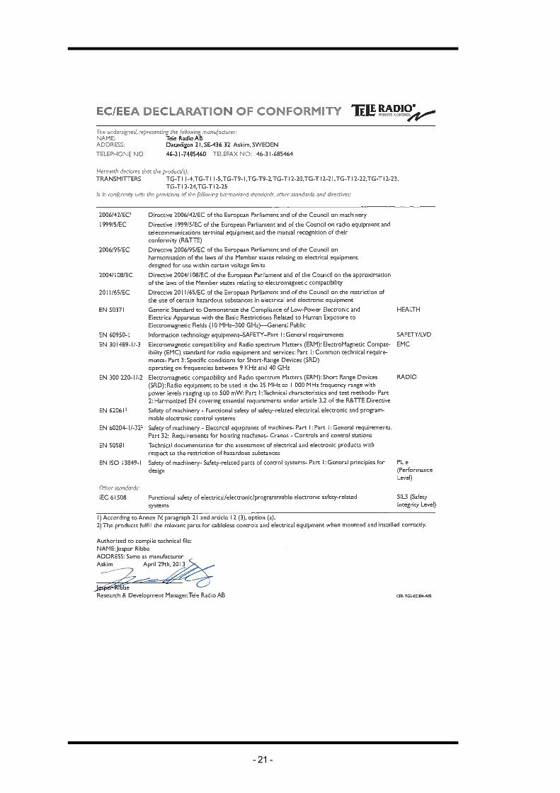
Chapter 3: EC DECLARATION OF CONFORMITY
- 21 -