Embed Size (px)
Citation preview
General
© 2006 Pyromation, Inc.
- TBL
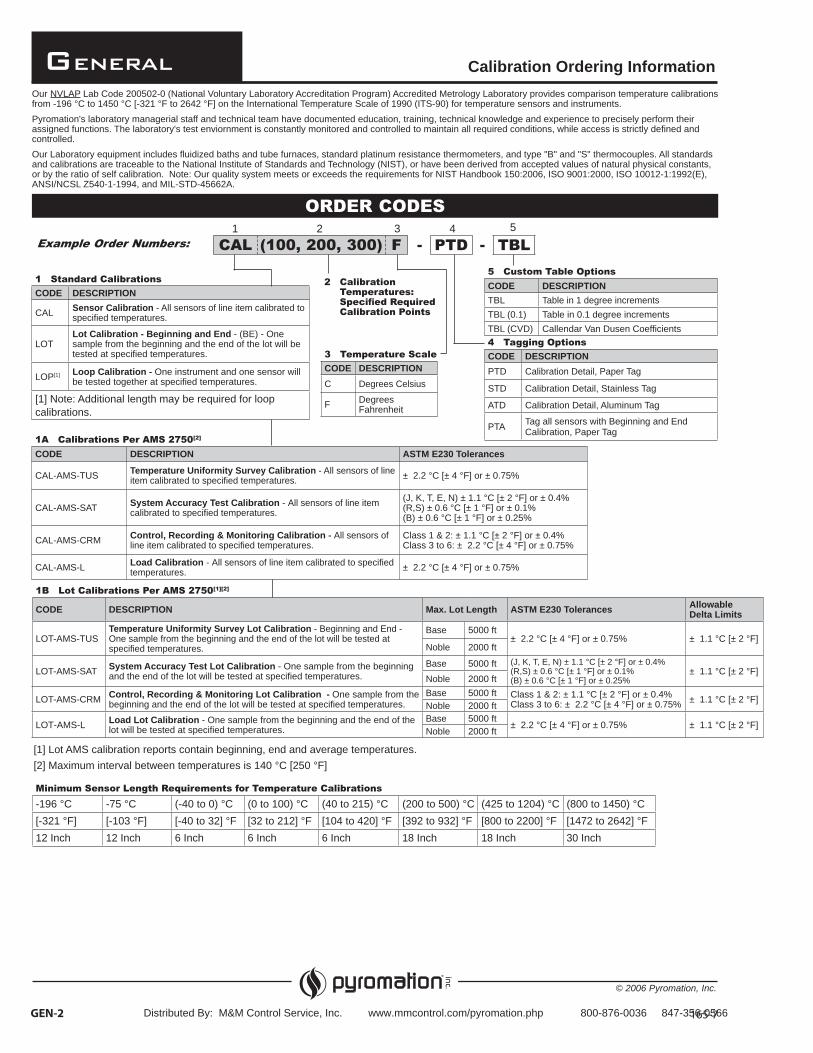
Calibration Ordering InformationOur NVLAP Lab Code 200502-0 (National Voluntary Laboratory Accreditation Program) Accredited Metrology Laboratory provides comparison temperature calibrations from -196 °C to 1450 °C [-321 °F to 2642 °F] on the International Temperature Scale of 1990 (ITS-90) for temperature sensors and instruments.Pyromation's laboratory managerial staff and technical team have documented education, training, technical knowledge and experience to precisely perform their assigned functions. The laboratory's test enviornment is constantly monitored and controlled to maintain all required conditions, while access is strictly defined and controlled.Our Laboratory equipment includes fluidized baths and tube furnaces, standard platinum resistance thermometers, and type "B" and "S" thermocouples. All standards and calibrations are traceable to the National Institute of Standards and Technology (NIST), or have been derived from accepted values of natural physical constants, or by the ratio of self calibration. Note: Our quality system meets or exceeds the requirements for NIST Handbook 150:2006, ISO 9001:2000, ISO 10012-1:1992(E), ANSI/NCSL Z540-1-1994, and MIL-STD-45662A.
ORDER CODES
Example Order Numbers:1 2 3
- PTD4
CAL (100, 200, 300) F5
1 Standard CalibrationsCODE DESCRIPTION
CAL Sensor Calibration - All sensors of line item calibrated to specified temperatures.
LOTLot Calibration - Beginning and End - (BE) - One sample from the beginning and the end of the lot will be tested at specified temperatures.
LOP[1] Loop Calibration - One instrument and one sensor will be tested together at specified temperatures.
[1] Note: Additional length may be required for loop calibrations.
1A Calibrations Per AMS 2750[2]
CODE DESCRIPTION ASTM E230 Tolerances
CAL-AMS-TUS Temperature Uniformity Survey Calibration - All sensors of line item calibrated to specified temperatures. ± 2.2 °C [± 4 °F] or ± 0.75%
CAL-AMS-SAT System Accuracy Test Calibration - All sensors of line item calibrated to specified temperatures.
(J, K, T, E, N) ± 1.1 °C [± 2 °F] or ± 0.4% (R,S) ± 0.6 °C [± 1 °F] or ± 0.1%(B) ± 0.6 °C [± 1 °F] or ± 0.25%
CAL-AMS-CRM Control, Recording & Monitoring Calibration - All sensors of line item calibrated to specified temperatures.
Class 1 & 2: ± 1.1 °C [± 2 °F] or ± 0.4%Class 3 to 6: ± 2.2 °C [± 4 °F] or ± 0.75%
CAL-AMS-L Load Calibration - All sensors of line item calibrated to specified temperatures. ± 2.2 °C [± 4 °F] or ± 0.75%
1B Lot Calibrations Per AMS 2750[1][2]
CODE DESCRIPTION Max. Lot Length ASTM E230 Tolerances Allowable Delta Limits
LOT-AMS-TUSTemperature Uniformity Survey Lot Calibration - Beginning and End - One sample from the beginning and the end of the lot will be tested at specified temperatures.
Base 5000 ft± 2.2 °C [± 4 °F] or ± 0.75% ± 1.1 °C [± 2 °F]
Noble 2000 ft
LOT-AMS-SAT System Accuracy Test Lot Calibration - One sample from the beginning and the end of the lot will be tested at specified temperatures.
Base 5000 ft (J, K, T, E, N) ± 1.1 °C [± 2 °F] or ± 0.4%(R,S) ± 0.6 °C [± 1 °F] or ± 0.1%(B) ± 0.6 °C [± 1 °F] or ± 0.25%
± 1.1 °C [± 2 °F]Noble 2000 ft
LOT-AMS-CRM Control, Recording & Monitoring Lot Calibration - One sample from the beginning and the end of the lot will be tested at specified temperatures.
Base 5000 ft Class 1 & 2: ± 1.1 °C [± 2 °F] or ± 0.4%Class 3 to 6: ± 2.2 °C [± 4 °F] or ± 0.75% ± 1.1 °C [± 2 °F]
Noble 2000 ft
LOT-AMS-L Load Lot Calibration - One sample from the beginning and the end of the lot will be tested at specified temperatures.
Base 5000 ft± 2.2 °C [± 4 °F] or ± 0.75% ± 1.1 °C [± 2 °F]
Noble 2000 ft
GEN-2
2 Calibration Temperatures: Spe i ed Re uired Calibration Points
4 Tagging OptionsCODE DESCRIPTIONPTD Calibration Detail, Paper Tag
STD Calibration Detail, Stainless Tag
ATD Calibration Detail, Aluminum Tag
PTA Tag all sensors with Beginning and End Calibration, Paper Tag
5 Custom Table OptionsCODE DESCRIPTIONTBL Table in 1 degree incrementsTBL (0.1) Table in 0.1 degree incrementsTBL (CVD) Callendar Van Dusen Coefficients
Minimum Sensor Lengt Re uirements or Temperature Calibrations-196 °C -75 °C (-40 to 0) °C (0 to 100) °C (40 to 215) °C (200 to 500) °C (425 to 1204) °C (800 to 1450) °C[-321 °F] [-103 °F] [-40 to 32] °F [32 to 212] °F [104 to 420] °F [392 to 932] °F [800 to 2200] °F [1472 to 2642] °F12 Inch 12 Inch 6 Inch 6 Inch 6 Inch 18 Inch 18 Inch 30 Inch
3 Temperature ScaleCODE DESCRIPTIONC Degrees Celsius
F Degrees Fahrenheit
[1] Lot AMS calibration reports contain beginning, end and average temperatures.[2] Maximum interval between temperatures is 140 °C [250 °F]
Distributed By: M&M Control Service, Inc. www.mmcontrol.com/pyromation.php 800-876-0036 847-356-0566

General
© 2006 Pyromation, Inc.
Operating Principles
GEN-525-8
THERMOCOUPLES - Thermocouples are the most common, convenient, and versatile devices used to measure temperature. They convert units of heat into useable engineering units that serve as input signals for process controllers and recorders.
A thermocouple consists of a welded 'hot' junction between two dissimilar metals - usually wires - and a reference junction at opposite ends of the parent materials. Heating the 'hot' junction in the working environment produces a temperature gradient which generates an Electromotive Force (EMF). The EMF appears across the free ends of the thermocouple wires where it is measured and converted into units of heat calibration. Through selection of appropriate thermocouple wires and sheath components, thermocouples are suitable to be used in temperature ranges from (-200 to 2316) °C [-328 to 4200] °F.
RESISTANCE TEMPERATURE DETECTORS - Resistance temperature detectors (RTD) accurately sense temperature with an excellent degree of repeatability and interchangeability of elements. The RTD is composed of certain metallic elements whose change in resistance is a function of temperature. In operation, a small excitation current is passed across the element, and the voltage, which is proportional to resistance, is then measured and converted to units of temperature calibration. The RTD element is manufactured by winding a wire (wire wound elements) or plating a film (thin film elements) on a ceramic or glass core and sealing the element within a ceramic or glass capsule.
Since most RTDs have a low initial resistance, often 100 ohms, and have a small change in resistance per unit of temperature range, the resistance of the lead wire is often compensated for with a three or four wire bridge configuration built into the measuring devices. By selecting the proper elements and protective sheathing, RTDs can operate in a temperature range of (-200 to 600) °C [-328 to 1112] °F.
THERMISTORS - A thermistor is an economical means of precisely sensing heat over a limited range of temperatures. A thermistor is a metal oxide whose change in resistance is typically an inverse function of the change in temperature. An excitation current is passed across the sensor and the voltage, which is proportional to the resistance, is measured and converted to units of heat calibration. Since thermistors usually have a large base resistance and a large change in resistance per unit of temperature change, compensation for lead wire length is not generally needed. Thermistors can operate across a temperature range of (-40 to 150) °C [-40 to 302] °F by selecting the proper sensor and protective materials.
ADDITIONAL REQUIREMENTS - Other components usually essential in integrating the principles of thermocouple, RTD, and thermistor sensors into a functioning system may include: (1) a protection tube or sheath of a material suitable to protect the sensing element from the environment surrounding the point of measurement; (2) a connecting head and terminal block, or possibly a temperature transmitter; (3) leadwire of the correct material and insulation to connect the temperature sensor and the process instrumentation; and (4) recording or controlling instrumentation and control devices to provide a continuous temperature history of the system and to provide constant or programmed temperature regulation.
Distributed By: M&M Control Service, Inc. www.mmcontrol.com/pyromation.php 800-876-0036 847-356-0566

General
© 2006 Pyromation, Inc.
Thermocouple Material Specifications
26-8GEN-6
The thermocouple element materials listed below are those most commonly found in process applications. Selection of the proper thermocouple type for a particular application is determined by temperature expectations and by the environment in which the sensor will be placed. The following temperature and application tables are intended to aid in this selection. The thermocouples are listed by ASTM letter designations per thermocouple type.
Letter Designated Thermocouples
TYPE TEMPERATURERANGE APPLICATION INFORMATION
JE230
Iron (+)Copper - 45% Nickel (Constantan) (-)
(0 to 760) °C[32 to 1400] °F
Suitable for vacuum, reducing, or inert atmospheres, oxidizing atmosphere with reduced life. Iron oxidizes rapidly above 538 °C [1000 °F] so only heavy gauge wire is recommended for high temperature. Bare elements should not be exposed to sulphurous atmospheres above 538 °C [1000 °F].
KE230
Nickel - 10% Chromium (+)Nickel - 2% Aluminum, 2% Manganese,1% Silicon (-)
(0 to 1260) °C[32 to 2300] °F
Recommended for continuous oxidizing or neutral atmospheres. Mostly used above 538 °C [1000 °F]. Subject to failure if exposed to sulphur. Preferential oxidation of chromium in positive leg at certain low oxygen concentrations causes 'green rot' and large negative calibration drifts most serious in the (816 to 1038) °C [1500 to 1900] °F range. Ventilation or inert-sealing of the protection tube can prevent this.
NE230
Nickel - 14% Chromium, 1 1/2% Silicon (+)Nickel - 4 1/2% Silicon - 1/10% Magnes-ium (-)
(0 to 1260) °C[32 to 2300] °F
Can be used in applications where Type K elements have shorter life and stability problems due to oxidation and the development of 'green rot'.
TE230
Copper (+)Copper - 45% Nickel (Constantan) (-)
(-200 to 370) °C[-328 to 700] °F
Useable in oxidizing, reducing, or inert atmospheres as well as vacuum. Not subject to corrosion in moist atmospheres. Limits of error published for sub-zero temperature ranges.
EE230
Nickel - 10% Chromium (+)Copper - 45% Nickel (Constantan) (-)
(0 to 870) °C[32 to 1600] °F
Recommended for continuously oxidizing or inert atmospheres. Sub-zero limits of error not established. Highest thermoelectric output of common calibrations.
RE230
Platinum - 13% Rhodium (+)Platinum (-)
(538 to 1482) °C[1000 to 2700] °F
Recommended for high temperature. Must be protected with non-metallic protection tube and ceramic insulators. Continued high temperature usage causes grain growth which can lead to mechanical failure. Negative calibration drift caused by Rhodium diffusion to pure leg as well as from Rhodium volatilization. Type R is used in industry; Type S in the laboratory.
SE230
Platinum - 10% Rhodium (+)Platinum (-)
BE230
Platinum - 30% Rhodium (+)Platinum - 6% Rhodium (-)
(871 to 1704) °C[1600 to 3100] °F
Same as R & S but output is lower. Also less susceptible to grain growth and drift.
CE230
95% Tungsten - 5% Rhenium (+)74% Tungsten - 26% Rhenium (-)
(0 to 2315) °C[32 to 4200] °F
Very high temperature applications in inert or vacuum. Preferred over Tungsten/Tungsten-26% Rhenium because it is less brittle at low temperatures.
Non-Letter Designated Thermocouples
TYPE TEMPERATURERANGE APPLICATION INFORMATION
ME1751
Nickel - 18% Molybdenum (+)Nickel - 0.8% Cobalt (-)
(-50 to 1410) °C[-58 to 2570] °F
High temperature applications in inert or vacuum atmosphere. Useful in many hydrogen applications. Continuous cycling causes excessive grain growth.
PE1751
Platinel II®
Platinel 5355 (+) Platinel 7674 (-)
(0 to 1395) °C[32 to 2543] °F
Noble metal combination which approximates Type K curve but has much improved oxidation resistance. Should be treated as any noble metal calibration.
Platinel® is a registered trademark of BASF Catalysts.
Distributed By: M&M Control Service, Inc. www.mmcontrol.com/pyromation.php 800-876-0036 847-356-0566

General
© 2006 Pyromation, Inc.
Thermocouple Initial Material Tolerances
GEN-7
Tolerances on Initial Values of EMF vs Temperature for ThermocouplesReference Junction 0 oC [32 oF]. Published in ASTM E230
TYPE TEMPERATURE RANGE for STANDARD TOLERANCES
STANDARD TOLERANCES
TEMPERATURE RANGE for SPECIAL TOLERANCES
SPECIAL TOLERANCES
J (0 to 293) °C(293 to 760) °C
± 2.2 °C [± 4 °F] ± 0.75%
(0 to 275) °C(275 to 760) °C
± 1.1 °C [± 2 °F]± 0.4%
K
(-200 to -110) °C(-110 to 0) °C(0 to 293) °C(293 to 1260) °C
± 2% [1]
± 2.2 °C [± 4 °F][1]
± 2.2 °C [± 4 °F]± 0.75%
(0 to 275) °C(275 to 1260) °C
[2]
[2]
± 1.1 °C [± 2 °F] ± 0.4%
N (0 to 293) °C(293 to 1260) °C
± 2.2 °C [± 4 °F][1]
± 0.75%(0 to 275) °C(275 to 1260) °C
± 1.1 °C [± 2 °F] ± 0.4%
T
(-200 to -67 °C(-67 to 0) °C(0 to 133) °C(133 to 370) °C
± 1.5%[1]
± 1 °C [± 1.8 °F][1]
± 1 °C [± 1.8 °F]± 0.75%
(0 to 125) °C(125 to 370) °C
[2]
[2]
± 0.5 °C [± 0.9 °F] ± 0.4%
E (0 to 870) °C ± 1.7 °C [± 3.06 °F][3]
or ± 0.5%(0 to 870) °C ± 1.0 °C [± 1.8 °F][3]
or ± 0.4%
R (0 to 600) °C(600 to 1480) °C
± 1.5 °C [± 2.7 °F]± 0.25%
(0 to 600) °C(600 to 1480) °C
± 0.6 °C [± 1.1 °F] ± 0.1%
S (0 to 600) °C(600 to 1480) °C
± 1.5 °C [ ± 2.7 °F]± 0.25%
(0 to 600) °C(600 to 1480) °C
± 0.6 °C [± 1.1 °F] ± 0.1%
B (870 to 1700) °C ± 0.5% (870 to 1700) °C ± 0.25%
C (0 to 400) °C(400 to 2315) °C
± 4.4 °C [± 8 °F]± 1.0% Not Available
[1] Thermocouples and thermocouple materials are supplied to meet the tolerance specified for temperatures above 0 °C. A thermocouple material may not conform to the published sub-zero limits of error for that material when purchased, unless conformance is agreed upon by customer and Pyromation when ordering.
[2] Special tolerances for sub-zero temperatures have not yet been established. The following limits for calibrations of types E and T are useful to start discussion between customer and Pyromation.
[3] The standard tolerances shown do not apply to Type E mineral-insulated, metal-sheathed (MIMS) thermocouples and thermocouple cables. The standard tolerances for MIMS Type E constructions are the greater of ± 2.2 °C or ± 1.75 % from 0 to 870 °C and the greater of ± 2.2 °C or ± 2 % from -200 to 0 °C.
Initial values of tolerance for Type J and special tolerance for Type K thermocouples below 0 °C are not given due to the characteristics of the materials.
Type T ± 0.5 °C or ± 0.8%, whichever is greater(-200 to 0) °C
[32 to 527] °F[527 to 1400] °F
[32 to 527] °F[527 to 2300] °F[32 to 527] °F[527 to 2300] °F
[32 to 257] °F[257 to 700] °F[32 to 1600] °F
[32 to 1112] °F[1112 to 2700] °F
The tolerances shown in the table below apply to new, essentially homogeneous thermocouple wire in the size range of 30 AWG to 8 AWG. These tolerances only apply to thermocouples used at temperatures not exceeding the recommended limits. If thermocouples are used at temperatures above the recommended limits, or in detrimental enviornments, the below stated tolerances may not apply.
[32 to 1112] °F[1112 to 2642] °F
Tolerances on Initial Values of EMF vs Temperature for Thermocouples
CODE MATERIAL TEMPERATURE RANGE TOLERANCE
M Ni18Mo/Ni (-50 to 1410) °C ± 0.75%
P Platinel® II (0 to 1395) °C ± 0.10 mV
[-58 to 2570] °F
[32 to 4200] °F
[32 to 559] °F[559 to 1400] °F[-328 to -166] °F[-166 to 32] °F[32 to 559] °F[559 to 2300] °F
[1600 to 3100] °F
[32 to 559] °F[559 to 2300] °F[-328 to -89] °F[-89 to 32] °F[32 to 271] °F[271 to 700] °F[32 to 1600] °F
[32 to 1112] °F[1112 to 2642] °F[32 to 1112] °F[1112 to 2700] °F
[32 to 752] °F[752 to 4200] °F
Platinel® is a registered trademark of BASF Catalysts.
[1600 to 3100] °F
Distributed By: M&M Control Service, Inc. www.mmcontrol.com/pyromation.php 800-876-0036 847-356-0566

General
© 2006 Pyromation, Inc.
Recommended Temperature Limits and Color Codes
28-8GEN-8
Thermocouples must be selected to meet application conditions and only general recommendations of size and type can be given. Selection considerations involve useful length of service life, temperature, atmosphere, and response time. Smaller gauges provide faster response times and less service life. Larger gauges provide longer service life and reduced response times. The recommended temperature limits below are to be used as a guideline in the selection process, and the table applies only to thermocouples protected by a suitable protecting tube, sheath, or well. The color coding chart below provides ANSI/ASTM standard color codes found on thermocouple wire, extension wire, and plug and jack connectors.
Suggested Upper Temperature Limits For Protected Industrial Thermocouples
TYPEMAXIMUM TEMPERATURE8 GAUGE 11 GAUGE 14 GAUGE 20 GAUGE 24 GAUGE 28 GAUGE 30 GAUGE
T°C °C °C °C °C °C °C
370 260 200 200 150J 760 590 480 370 370 320E 870 650 540 430 430 370K, N 1260 1090 980 870 870 760M 1287 1287R, S 1480B 1700C 2330
[700] [400]
[2250]
[1400]
[°F]
[800]
[300]
[1600][2300]
[°F] [°F] [°F] [°F] [°F] [°F]
[2250]
[1100][1200][2000]
[700][800][1600]
[2700][3100][4200]
[400]
[1600]
[700] [600][700][1400]
[500][900][1000][1800]
+-
THERMO-COUPLE
TYPE
U.S. & CANADIAN (ANSI/ASTM E230, ANSI/MC96.1)
ALLOY COMBINATION
THERMOCOUPLEGRADE
EXTENSION GRADE
PLUG & JACK
TCopper
Constantan(Copper-Nickel)
Blue
JIron
(magnetic)
Constantan(Copper-Nickel)
Black
ENickel - Chromium
Constantan(Copper- Nickel)
Purple
KNickel - Chromium Nickel - Aluminium
(magnetic)
Yellow
NNicrosil
(Nickel-Chromium- Silicon)
Nisil(Nickel-Silicon-Magnesium)
Orange
SPlatinum
Rhodium -10%
Platinum
None Established
Green
RPlatinum
Rhodium -13%
Platinum
None Established
Green
BPlatinum
Rhodium - 30%
PlatinumRhodium - 6%
None Established
(Compensated Cable)
White(Uncom-
pensated)
CTungsten
Rhenium - 5%
TungstenRhenium - 26%
None Established
Red
+-
BrownBlue
Red
+-
Blue
Red
Blue
+-
Brown Orange
Red
+-
Orange
Red
Orange
+-
BrownYellow
Red
+-
Yellow
Red
Yellow
+-
BrownPurple
Red
+-
Purple
Red
Purple
+-
BrownWhite
Red
+-
White
Red
Black
+-
Black
Red
Green
+-
Black
Red
Green
+-
Gray
Red
Gray
Green
Red
Red
Distributed By: M&M Control Service, Inc. www.mmcontrol.com/pyromation.php 800-876-0036 847-356-0566

General
© 2006 Pyromation, Inc.
Tubing, Sheath, Protection Tube,and Well Materials
GEN-9
Pyromation provides a variety of common tubing, MgO sheath, protection tube, and drilled-well materials to protect temperature sensing elements from the environmental conditions typically found in industrial process applications. The following tables are intended as guidelines to aid in the selection of the proper materials for sensors used in different environments. Consult the factory for the availability of other protective materials for specialty applications. NOTE: All chemical compositions and temperature ratings are nominal and are stated as received from suppliers.
Material Code IndexMETALS CERAMICS and COMPOSITE MATERIALS
CODE MATERIAL CODE MATERIAL CODE MATERIAL CODE MATERIAL
23456789[2]
11222324
MolybdenumAlloy 600310 S.S.446 S.S.Carbon Steel Alloy 601316 S.S.304 S.S.Cast IronBrassCopperPlatinum
25262728293132333536
TantalumTitaniumAlloy 400Alloy BAlloy C -276Nickel 200304 LC S.S.316 LC S.S.321 S.S.347 S.S.
3738415059606191
Alloy 800Alloy 20HR - 160®
ZirconiumF22-1F11-2A105F91
121314151617181971
Metal Ceramic LT-1VesuviusCerite® - IICerite® - IIIMulliteAluminaSilicon CarbideHexoloy® SARecrystallized Silicon Carbide
MetalsCATALOGMATERIALCODE
MATERIAL/COMPOSITIONTYPICAL AREAS OF USE
APPLICATION GUIDELINE INFORMATIONTUBING MGO
SHEATHSPROT. TUBES
DRILLED WELLS
2 MOLYBDENUM99.9% min. Molybdenum, 0.03% Tungsten
X X Up to 1926 °C [3500 °F] in inert atmospheres, to 1871 °C [3400 °F] in vacuum at 10-4 torr. Has poor mechanical shock resistance after heated to 1038 °C [1900 °F]. Oxidizes in air above 427 °C [800 °F].
3 ALLOY 600 (UNS N06600)72% Nickel, 15% Chromium, 8% Iron
X X X X Up to 1149 °C [2100 °F] under oxidizing conditions. Reducing conditions reduce maximum temperature to 1038 °C [1900 °F]. Must not be placed in sulfurous atmospheres above 538 °C [1000 °F]. Main areas of application for thermocouple protection are carburizing, annealing and hardening furnaces, Cyanide saltbaths, blast furnace downcomers, open hearth flue stacks, steel soaking pits, waste heat boilers, ore roasters, cement exit flues, incinerators, and glass tank flues. (INCONEL® 600)
4 310 STAINLESS STEEL (UNS S31000)25% Chromium, 20% Nickel
X X X X Up to 1038 °C [1900 °F] continuous, 1149 °C [2100 °F] intermittent. Mechanical and corrosion resistance similar to and better than 304 stainless steel.
5 446 STAINLESS STEEL (UNS S44600)27% Chromium
X X X Up to 1093 °C [2000 °F] under oxidizing conditions. Excellent high temperature corrosion and oxidizing resistance. Main areas of application are hardening, nitriding, and annealing furnaces, salt baths, molten lead, tin and babbitt metal, sulfurous atmospheres. Not for carburizing atmospheres. Other areas of application are steel soaking pits, tinning pots, waste heat boilers, ore roasters, cement exit flues, boiler tubes to 982 °C [1800 °F], incinerators to 1093 °C [2000 °F], glass flue tanks.
6 CARBON STEEL[1] X X X Up to 538 °C [1000 °F] in non-oxidizing environments. Main areas of usage are galvanizing pots, tinning pots, molten babbitt metal, molten mangesium, molten zinc, Petroleum refinery applications such as dewaxing and thermal cracking.
7 ALLOY 601 (UNS N06601)61% Nickel, 23% Chromium, 14% Iron,1.35% Aluminum
X X X Similar applications to Inconel® 600 but with superior resistance to sulfur, high temperature oxidation resistance to 1260 °C [2300 °F]. (INCONEL® 601)
8 316 STAINLESS STEEL (UNS S31600)16% Chromium, 12% Nickel2% Molybdenum
X X X X Up to 927 °C [1700 °F] under oxidizing conditions. Same areas of applications as 304 stainless steel. Has improved resistance to mild acid and pitting corrosion.
9[2] 304 STAINLESS STEEL (UNS S30400)18% Chromium, 8% Nickel
X X X X Up to 899 °C [1650 °F] under oxidizing conditions. Has general good oxidation and corrosion resistance in a wide range of industrial environments. Subject to carbide precipitation, which can reduce corrosion resistance in the (427 to 538) °C [800 to 1000] °F range. Good mechanical properties from (-184 to 788) °C [-300 to 1450] °F. Main areas of usage for thermocouple protection is in chemicals, foods, plastics and petroleum. Generally regarded as standard protection tube material.
[1] Materials available in various alloys - consult factory[2] Machined fittings may be supplied as 303 Series stainless steelHexoloy® is a registered trademark of Saint-Gobain Ceramics CorporationINCONEL® is a registered trademark of Special Metals CorporationHR-160® is a registered trademark of Haynes International, Inc.
Distributed By: M&M Control Service, Inc. www.mmcontrol.com/pyromation.php 800-876-0036 847-356-0566

General
© 2006 Pyromation, Inc.
Tubing, Sheath, Protection Tube,and Well Materials
GEN-10
Metals
CATALOGMATERIALCODE MATERIAL/COMPOSITION
TYPICAL AREAS OF USEAPPLICATION GUIDELINE INFORMATION
TUBING MGO SHEATHS
PROT. TUBES
DRILLED WELLS
11 CAST IRON X Up to 704 °C [1300 °F] in oxidizing conditions. Main area of usage is in molten non-ferrous metals, daily whiting is recommended. Can be used to 871 °C [1600 °F] under reducing conditions.
22 BRASS[1] X X Up to 538 °C [1000 °F] continuous. Good thermal conductivity and mechanical strength.
23 COPPER X XLimited Avail.
Up to 260 °C [500 °F] continuous. Excellent thermal conductivity. Poor mechanical strength.
24 PLATINUM[1] X X Up to 1374 °C [2500 °F] continuous oxidizing atmospheres. Good thermal conductivity. Used in applications where high temperature, but no vacuum or inert atmosphere is available.
25 TANTALUM[2] X X X[2] Up to 2349 °C [4350 °F]. Good resistance to corrosion and quick heat conductivity. Good mechanical strength. Used in chemical processes and high temperatures in vacuum or inert atmosphere.
26 TITANIUM X X X Up to 1260 °C [2300 °F] in inert or vacuum atmosphere. Acid and chemical resistant. Oxidation resistance to 538 °C [1000 °F].
27 ALLOY 400 (UNS N04400) 67% Nickel30% Copper
X X X X Up to 538 °C [1000 °F] in sulfur-free atmosphere. Excellent resistance to corrosion. Used in chemical processing and food processing equipment. MONEL® 400
28 ALLOY B (UNS N10001) 62% Nickel28% Molybdenum,5% Iron
X XLimited Avail.
X X Up to 815 °C [1500 °F] in inert or vacuum atmospheres. 538 °C [1000 °F] in air. Has excellent resistance to pitting, to stress-corrosion cracking. Suitable for most chemical processes. Application excellent in hydrochloric acid. (HASTELLOY® B)
29 ALLOY C-276 (UNS N10276)54% Nickel16% Molybdenum,15% Chromium
X XLimited Avail.
X X Up to 1038 °C [1900 °F] in oxidizing atmospheres. Exceptional resistance to a wide variety of chemical environments. Withstands wet chlorine gas, hypochlorite and chlorine dioxide. (HASTELLOY® C-276)
31 NICKEL 200 (UNS N02200) 99% Nickel
XLimited Avail.
X Up to 899 °C [1650 °F] in sulfur-free atmospheres. Good corrosion-resistance. Used in contact with reducing acids, foods, chemicals caustics, rayon, and plastics.
32 304 STAINLESS STEEL LOW CARBON(UNS S30403)18% Chromium, 8% Nickel
X X X X Same characteristics as 304 except the low carbon allows for corrosion-resistant weld areas. Not recommended to be used above 427 °C[800 °F]. (0.03% max. carbon)
33 316 STAINLESS STEEL LOW CARBON(UNS S31603)16% Chromium12% Nickel2% Molybdenum
X X X X Same characteristics as 316 except the low carbon allows for corrosion-resistant weld areas. Not recommended to be used above 427 °C[800 °F]. (0.03% max. carbon)
35 321 STAINLESS STEEL (UNS S32100) 18% Chromium10% Nickel, Titanium
X X X X Good corrosion resistance between (482 to 871) °C [900 to 1600] °F. Used where conditions are too severe for low carbon stainless steels.
36 347 STAINLESS STEEL (UNS S34700)18% Chromium, 10% Nickel,Columbium
X XLimited Avail.
X Good corrosion resistance between (482 to 871) °C [900 to 1600] °F. Used where conditions are too severe for low carbon stainless steels.
37 ALLOY 800 (UNS N08800)33% Nickel 42% Iron21% Chromium
X XLimited Avail.
X X Strong resistance to oxidation and carburization at high temperatures. Resists sulfur attack, internal oxidation, and scaling in a wide variety of atmospheres. (INCOLOY® 800)
38 ALLOY 20 (UNS N08020)35% Nickel 35% Iron20% ChromiumColumbium
XLimited Avail.
X X Superior resistance to stress-corrosion cracking in boiling 20-40% sulfuric acid. Also used in high octane gas, solvents, explosives, heavy chemicals and agri-chemicals. (CARPENTER 20Cb-3®)
41 HR - 160® (UNS N12160)37% Nickel30% Cobalt28% Chromium
X X A premier alloy that provides excellent resistance to sulphur, vanadium, chlorines, chlorides, and other salt deposits up to 1204 °C [2200 °F]. A superior material for use in aggressive waste incineration processes.
[1] Materials available in various alloys - consult factory[2] Generally applied as a well jacketMONEL® and INCOLOY® are registered trademarks of Special Metals CorporationHASTELLOY® is a registered trademark of Hayman International, Inc.20Cb-3® is a registered trademark of Carpenter Technology CorporationHR-160® is a registered trademark of Haynes International, Inc.
Distributed By: M&M Control Service, Inc. www.mmcontrol.com/pyromation.php 800-876-0036 847-356-0566

General
© 2006 Pyromation, Inc.
Tubing, Sheath, Protection Tube,and Well Materials
GEN-11
Ceramics and Composite MaterialsCATALOGMATERIALCODE
MATERIAL/ COMPOSITIONTYPICAL AREAS OF USE
APPLICATION GUIDELINE INFORMATIONTUBING MGO
SHEATHSPROT. TUBES
DRILLED WELLS
12 METAL CERAMIC LT-1(slip cast composite of chromiumand aluminum oxide,) 77%chromium, 23% aluminum oxide
X Up to 1374 °C [2500 °F] in oxidizing conditions. Main areas of usage are molten copper base alloys to 1149 °C [2100 °F], blast furnace and stack gases to 1316 °C [2400 °F], Sulfur burners to 1093 °C [2000 °F], cement kilns to 1204 °C [2200 °F], chemical process reactors to 1371 °C [2500 °F]. A ceramic primary tube is required when a noble metal thermocouple is used.
13 VESUVIUS X Up to 927 °C [1700 °F]. For use in aluminum and other non-ferrous metals. Not wetted by molten aluminum and other non-ferrous metals. No contamination. Resists thermal and mechanical shock. Brittle after heating. Handle carefully.
14 CERITE®-II (Cast oxide composites) X Up to 1093 °C [2000 °F]. For submerged use in aluminum and other non-ferrous metals. Not wetted by molten aluminum and other non-ferrous metals. No contamination. Good thermal and mechanical shock resistance.
15 CERITE®-III (Cast oxide composites) X Up to 1093 °C [2000 °F]. For submerged use in aluminum and other non-ferrous metals. Not wetted by molten aluminum and other non-ferrous metals. No contamination. Good thermal and mechanical shock resistance.
16 MULLITE63% alumina
X Up to 1510 °C [2750 °F] when supported. Has poor mechanical shock resistance, but good thermal shock resistance. For barium chloride salt baths to 1288 °C [2350 °F]. Should be vertical mounted or supported if horizontal. For high temperature applications of ceramic industry, heat treating, glass manufacture. Impervious to gases at high temperatures.
17 ALUMINA(Recrystallized 99.7% AL2O3)
X Up to 1889 °C [3400 °F] when supported. Has only fair resistance to thermal and mechanical shock. Essentially same applications as Mullite including induction melting, vacuum furnaces. Impervious to gases at high temperatures.
18 SILICON CARBIDE90% silicon carbide, 9% silicon dioxide, balance aluminum oxide
X Up to 1650 °C [3000 °F]. For an outer protection tube with Alumina® or mullite primary tube. For brick and ceramic kilns, steel soaking pits, molten non-ferrous metals. Can withstand direct flame impingement. Fair thermal shock resistance. Approximately 14% porosity.
19 HEXOLOY® SAsintered alpha, silicon carbide
X Up to 1650 °C [3000 °F] in air. High thermal conductivity, excellent wear and abrasion resistance, high thermal shock resistance, and good mechanical strength. Superior chemical resistance in both reducing and oxidizing environments. Attacked by Halides, fused caustics, and ferrous metals.
71 RECRYSTALLIZED SILICON CARBIDE(Halsic R) 99% silicon
X Up to 1600 °C [2912 °F] in oxidizing atmosphere, and 2000 °C [3632 °F] in a vacuum atmosphere. Used as an outer protection tube in hot stack emissions, combustion chambers, chemical reactors, and incineration of medical, municipal, and industrial waste. Can withstand direct flame impingement, has excellent thermal shock characteristics, and excellent corrosion resistance. A ceramic inner tube is required when used with noble metal thermocouples.
MetalsCATALOGMATERIALCODE
MATERIAL/COMPOSITIONTYPICAL AREAS OF USE
APPLICATION GUIDELINE INFORMATIONTUBING MGO
SHEATHSPROT. TUBES
DRILLED WELLS
50 ZIRCONIUM (UNS R60702)99.2% Zr
X X X Up to 400 °C [752 °F]. Zirconium has a high affinity to oxygen that results in the formation of a regenerative protective oxide layer in most media. This oxide layer gives the material chemical resistance and erosive resistance in high velocity applications. Zirconium is resistant to corrosion from most organic and inorganic acids and salts and it is totally resistant to alkalis.
59 F22 (UNS K21590)Cr 2.25%, Mo 1%
X X Carbon steel alloy typically used in power plant, boiler and turbine applications.
60 F11 (UNS K11572)Cr 1.25%, Mo .5%, Si
X X Carbon steel alloy typically used in power plant, boiler and turbine applications.
61 A105C, Si
X Carbon steel alloy typically used in power plant, boiler and turbine applications.
91 F91 (UNS K91560)Cr 9%, Mo 1%, V
X X Chrome Moly alloy typically used in power plant, boiler and turbine applications.
Hexoloy® is a registered trademark of Saint-Gobain Ceramics Corporation
Distributed By: M&M Control Service, Inc. www.mmcontrol.com/pyromation.php 800-876-0036 847-356-0566

General
© 2006 Pyromation, Inc.
General MgO Specifications
UNGROUNDED JUNCTION (U)The welded thermocouple junction is fully isolated from the welded closure of the sheath. This junction provides electrical isolation to reduce problems associated with electrical interference. Ungrounded junctions are also recommended for use in extreme positive or negative temperatures, rapid thermal cycling and for ultimate corrosion resistance of the sheath alloy. All ungrounded
@ 500 V dc at ambient room temperatures.
GROUNDED JUNCTION (G)The thermocouple junction is welded securely into the closure end of the sheath, becoming an integral part of the weld. This is a good general purpose, low cost junction providing faster response times than an un-grounded junction of similar sheath diameter. Grounded junctions should not be used with Type T thermocouples, due to the copper wire.
EXPOSED JUNCTION (E)The thermocouple wires are welded and exposed. The insulation is not sealed against liquid or gas penetration. Recommended where fast response is desired, and corrosive conditions are nonexistent. The exposed hot junction length for 1/8-inch diameter sheaths and above is typically 3/16" past sheath. The exposed junctions for sheath diameters less than 1/8-inch diameter are supplied as shielded junctions.
HOT or MEASURING JUNCTIONS and RESPONSE TIMES
Thermocouple Types and Sizes
SHEATH DIAMETER (inches) - AWG WIRE SIZETYPE MATERIAL 0.020 O.D. 0.032 O.D. 0.040 O.D. 1/16 O.D. 1/8 O.D. 3/16 O.D. 1/4 O.D. 3/8 O.D.E Chromel-Constantan 38 35 32 30 24 21 19 15J Iron-Constantan 38 35 32 30 24 21 19 15K Chromel-Alumel 38 35 32 30 24 21 19 15T Copper-Constantan 38 35 32 30 24 21 19 15N Nicrosil-Nisil 38 35 34 - 29 21 19 15
Recommended Upper Temperature Limits For Protected ThermocouplesUpper Temperature Limits (F) For Various Sheath & Diameter Combinations
SHEATHTYPE
SHEATHMATERIAL
SHEATH DIAMETER (inches)
0.020, 0.032, 0.040 1/16 1/8 3/16 1/4 3/8
TEMPERATURE RANGE
J
316 S.S.
(0 to 260) °C[32 to 500] °F
(0 to 441) °C [32 to 825] °F
(0 to 521) °C [32 to 970] °F
(0 to 621) °C [32 to 1150] °F
(0 to 721) °C [32 to 1330] °F
(0 to 721) °C [32 to 1330] °F
K or N (0 to 700) °C[0 to 1290] °F
(-200 to 921) °C [-328 to 1690] °F
(-200 to 927) °C [-328 to 1700] °F
(-200 to 927) °C [-328 to 1700] °F
(-200 to 927) °C [-328 to 1700] °F
(-200 to 927) °C [-328 to 1700] °F
E (-200 to 260) °C[-328 to 570] °F
(-200 to 510) °C [-328 to 950] °F
(-200 to 649) °C [-328 to 1200] °F
(-200 to 732) °C [-328 to 1350] °F
(-200 to 821) °C [-328 to 1510] °F
(-200 to 821) °C [-328 to 1510] °F
T (-200 to 260) °C[-324 to 500] °F
(-200 to 260) °C [-328 to 500] °F
(-200 to 371) °C [-328 to 700] °F
(-200 to 371) °C [-328 to 700] °F
(-200 to 371) °C [-328 to 700] °F
(-200 to 371) °C [-328 to 700] °F
K or NALLOY600
(0 to 700) °C[0 to 1290] °F
(-200 to 921) °C [-328 to 1690] °F
(-200 to 1071) °C [-328 to 1960] °F
(-200 to 1149) °C [-328 to 2100] °F
(-200 to 1149) °C [-328 to 2100] °F
(-200 to 1149) °C [-328 to 2100] °F
E (-200 to 300) °C[-328 to 570] °F
(-200 to 510) °C [-328 to 950] °F
(-200 to 649) °C [-328 to 1200] °F
(-200 to 732) °C [-328 to 1350] °F
(-200 to 821) °C [-328 to 1510] °F
(-200 to 821) °C [-328 to 1510] °F
Typical Junction Response Times(63.2% of a (25 to 100) ºC Step Change)
SHEATHO.D. (inches)
"E"JUNCTION(seconds)
"G"JUNCTION(seconds)
"U"JUNCTION(seconds)
0.020 0.02 s 0.03 s 0.24 s
0.032 0.03 s 0.05 s 0.26 s
0.040 0.03 s 0.06 s 0.28 s
1/16 0.01 s 0.3 s 0.4 s
1/8 0.1 s 0.6 s 1.6 s
3/16 0.2 s 0.9 s 2.4 s
1/4 0.3 s 1.3 s 2.9 s
3/8 0.4 s 3.5 s 7.2 sSHIELDED JUNCTION (S)The thermocouple wires are welded and recessed inside the sheath with the tip of the sheath open. Insulation is not sealed against process conditions.
This table gives the suggested upper temperature limits for various thermocouples in several common sheath sizes. It does not address compatibility considerations between the thermoelement materials and the sheath containing them. The temperature limits given here are intended only as a guide to the purchaser and should not be taken as absolute values, nor as guarantees of satisfactory life or performance. These types and sizes are sometimes used at temperatures above the given limits, but usually at the expense of stability, life or both. In other instances, it may be necessary to reduce the given limits in order to achieve adequate service.
The information contained in the following pages is intended as a guideline only for general sensor usage. The specific application and the enviornmental conditions may require that other sensor sheath materials, diameters, or construction styles be used to provide optimum temperature measurement results. The dimensions, temperature ratings, and response times indicated are nominal, and they may vary in actual practice.
449-1GEN-12
EXPOSED JUNCTION (E)
Distributed By: M&M Control Service, Inc. www.mmcontrol.com/pyromation.php 800-876-0036 847-356-0566

General
© 2006 Pyromation, Inc.
Elements of several different materials, base resistances, temperature coefficients, accuracies, and construction styles are available for installation into final RTD temperature sensor assemblies to meet customer specifications. Pyromation's standard RTD constructions utilize both
LOW RANGE - THIN-FILM CONSTRUCTION (L) (-50 to 200) °C [-58 to 392] °F
moisture penetration.
LOW RANGE - WIRE-WOUND CONSTRUCTION (L) (-200 to 200) °C [-328 to 392] °F
moisture penetration.
MEDIUM RANGE - THIN-FILM CONSTRUCTION (M) (-50 to 480) °C [-58 to 896] °F
moisture penetration.
MEDIUM RANGE - THIN-FILM CONSTRUCTION (K) (-50 to 315) °C [-58 to 599] °F
moisture penetration.
HIGH RANGE - WIRE-WOUND CONSTRUCTION (H) (-200 to 600) °C [-328 to 1112] °F
HIGH RANGE - THIN-FILM CONSTRUCTION (H) (-50 to 500) °C [-58 to 932] °F
RTD Element Terminology
TEMPERATURE COEFFICIENT OF RESISTANCE: °C , °C or °C or °C
TOLERANCE: t t t
SELF-HEATING:
THERMAL RESPONSE: 0.9, 0.5, or
MINIMUM IMMERSION DEPTH:
REPEATABILITY-STABILITY: ±
VIBRATION:
HUMIDITY LIMITS: normal ambient temperatures.
INTERCHANGEABILITY:
RTD Specifications and Terminology
450-2 GEN-13Distributed By: M&M Control Service, Inc. www.mmcontrol.com/pyromation.php 800-876-0036 847-356-0566

General
© 2006 Pyromation, Inc.
RTD Specifications
Element ConnectionsTwo-Wire: Provides one connection to each end of the element. This construction is suitable where the resistance of the lead wire may be considered as an additive constant in the circuit, and particularly where the changes in lead resistance due to ambient temperature changes may be ignored.
Three-Wire: Provides one connection to one end of the element and two to the other end of the element. Connected to
Four-Wire: Provides two connections to each end of the element to completely compensate for leadwire resistance and
3-WIRE SINGLE2-WIRE SINGLE 2-WIRE DUPLEX 3-WIRE DUPLEX 4-WIRE SINGLE 4-WIRE DUPLEX
Leadwire Resistance
LEADWIRE-WIREGAUGE
RESISTANCE-OHMS PERFOOT
UNCOMPENSATED 2-WIRE CIRCUITS
MAX. LENGTHFOR 1 °FERROR @ 20 °C [68 °F]
ERROR IN °FPERDOUBLE FT.
30 0.133 0.81 ft 1.24 °F
28 0.0851 1.26 ft 0.79 °F
24 0.0333 3.2 ft 0.31 °F
22 0.0213 5.1 ft 0.198 °F
20 0.0148 7.27 ft 0.14 °F
18 0.0083 13.0 ft 0.077 °F
16 0.0052 20.7 ft 0.048 °F
Lead resistance has a large effect on RTD temperature measurement accuracy. A 2-wire circuit provides no compensation and can provide large measurement errors. The following table shows the effects of leadwire resistance on temperature measurements using low-temperature RTD assemblies with copper leadwire.
451-1GEN-14
WHITE
RED
GREEN
BLACK
WHITE
RED
WHITE
REDRED
GREEN
BLACKBLACK
REDRED
WHITE
WHITE
REDRED
WHITEGREEN
BLACKBLACK
GREEN
WHITE
REDRED
WHITE
WHITE
RED
RED
WHITE
RED
RED
Distributed By: M&M Control Service, Inc. www.mmcontrol.com/pyromation.php 800-876-0036 847-356-0566

General
© 2006 Pyromation, Inc.
TEMPERATUREIEC CLASS B [1]
± (0.12% × RO
ASTM GRADE B [1]
± (0.1% × RO
IEC CLASS A [1]
± (0.06% × RO
IEC CLASS AA [1]
± (0.04% × RO
(1/5) IEC CLASS B [2]
± (0.02% × RO
± (0.3 + 0.005 |t| ) °C ± (0.25 + 0.0042 |t| ) °C ± (0.15 + 0.002 |t| ) °C ± (0.1 + 0.0017 |t| ) °C ± (0.06 + 0.001 |t| ) °C
°C [°F] °C [°F] °C [°F] °C [°F] °C [°F] °C [°F]-200 [-328] 1.09 [1.96] 0.55 [0.99] 0.44 [0.79] 0.26 [0.47]-100 [-148] 0.67 [1.21] 0.35 [0.63] 0.27 [0.49] 0.16 [0.29]-50 [-58] .55 [0.99] 0.46 [0.83] 0.25 [0.45] 0.19 [0.34] 0.11 [0.20]0 [32] .30 [0.54] 0.25 [0.45] 0.15 [0.27] 0.10 [0.18] 0.06 [0.11]
100 [212] .80 [1.44] 0.67 [1.21] 0.35 [0.63] 0.27 [0.49] 0.16 [0.29]200 [392] 1.3 [2.34] 1.09 [1.96] 0.55 [0.99] 0.44 [0.79] 0.26 [0.47]300 [572] 1.8 [3.24] 1.51 [2.72] 0.75 [1.35]400 [752] 2.3 [4.14] 1.93 [3.47] 0.95 [1.71]500 [932] 2.8 [5.04] 2.35 [4.23] 1.15 [2.07]600 [1112] 2.77 [4.99] 1.35 [2.43]
STANDARD PLATINUM RTD ASSEMBLIES - Pyromation standard RTD assemblies are constructed
at 0 -1
1. International Standard, IEC 60751 2. American Standard, ASTM E1137
°C
[2] This tolerance can only be met with a 4-wire PRT.
GEN-15
RTD Tolerances
452-1 Distributed By: M&M Control Service, Inc. www.mmcontrol.com/pyromation.php 800-876-0036 847-356-0566

General
© 2006 Pyromation, Inc.
Leadwire Transition Fitting Dimensions
CODESHEATHDIAMETERS(inches)
FITTINGO.D.(inches)
FITTING LENGTHW/SPRING(inches)
W/O SPRING(inches)
15,16,19 0.020 3/8 2 (5/8) 1 (3/16)
15,16,19 0.032 3/8 2 (5/8) 1 (3/16)
15,16,19 0.040 3/8 2 (5/8) 1 (3/16)
15,16,19 1/16 1/4 2 (5/8) 1 (3/16)
15,16,19 1/16[1] 3/8 2 (5/8) 1 (3/16)
15,16,19 1/8 1/4 2 (5/8) 1 (3/16)
15,16,19 1/8[1] 3/8 2 (5/8) 1 (3/16)
15,16,19 3/16 3/8 2 (5/8) 1 (3/16)
15,16,19 1/4 3/8 2 (5/8) 1 (3/16)
15,16,19 3/8 7/16 2 (5/8) 1 (3/16)
[1] Used with flexible armor tubing, duplex T/C's, and wire codes P3, P1, and F3
Sheath Mounting Fitting Dimensions
CODE STYLE SHEATH O.D.(inches)
NPT SIZE(inches)
LENGTH(inches)
01A 303 SS one-time adjustable 1/16, 1/8, 3/16, 1/4 1/8 1 5/16
05A 316 SS one-time adjustable 1/16, 1/8, 3/16, 1/4 1/8 1 1/4
05B 316 SS one-time adjustable 1/8, 3/16, 1/4, 3/8 1/4 1 7/8
05C 316 SS one-time adjustable 1/8, 1/4, 3/8 1/2 1 13/16
15A Brass one-time adjustable 1/8, 3/16, 1/4 1/8 1 1/4
15B Brass one-time adjustable 3/16, 1/4, 3/8 1/4 1 3/8
15C Brass one-time adjustable 1/4, 3/8 1/2 1 1/2
10A 303 SS re-adjustable 1/16, 1/8, 3/16 1/8 1 1/4
10B 303 SS re-adjustable 1/4, 3/8 1/4 2 7/16
10C 303 SS re-adjustable 1/4, 3/8 1/2 2 7/16
12A 316 SS re-adjustable 1/16, 1/8, 3/16, 1/4 1/8 1 1/4
12B 316 SS re-adjustable 1/8, 3/16, 1/4, 3/8 1/4 1 1/2
12C 316 SS re-adjustable 1/8, 1/4, 3/8 1/2 1 3/4
11A Brass re-adjustable 1/16, 1/8, 3/16, 1/4 1/8 1 19/64
11B Brass re-adjustable 1/8, 3/16, 1/4, 3/8 1/4 1 9/16
11C Brass re-adjustable 1/4, 3/8 1/2 1 13/16
19C 303 SS spring-loaded well ftg. 3/16, 1/4 1/2 2 1/4
8A All sizes 1/8 5/8
8B All sizes 1/4 11/16
8C All sizes 1/2 15/16
8D All sizes 3/4 1
6HN 1/8, 3/16, 1/4, 3/8 1/2 2
8HN 1/8, 3/16, 1/4, 3/8 1/2 2
8RNDC 1/8, 3/16, 1/4, 3/8 3/4 x 1/2 2
9HNB 1/8, 3/16, 1/4, 3/8 1/4 1 3/16
13A 1/8, 3/16 N/A 1 5/8
14 1/8, 3/16, 1/4, 3/8 N/A 1 1/2
16A 1/8 N/A 1 5/8
Compression Fitting Pressure Rating Table
CODE 05A05A, 05B, 05C
05A,05B
05A,05B, 05C
05B,05C
Sheath O.D. &Wall Thickness
1/6" O.D.x 0.0077"
1/8" O.D.x 0.012"
3/16" O.D.x 0.020"
1/4" O.D.x 0.028"
3/8" O.D.x 0.049"
TEMPERATURE MAXIMUM ALLOWANCE WORKING PRESSURE (PSIG)
(-29 to 149) ºC[-20 to 300] ºF 3300 2850 3150 3350 3900
204 ºC [400 ºF] 3200 2750 3050 3250 3800
260 ºC [500 ºF] 3000 2550 2850 3000 3500
316 ºC [600 ºF] 2800 2400 2700 2850 3300
371 ºC [700 ºF] 2700 2350 2600 2750 3200
427 ºC [800 ºF] 2650 2300 2550 2650 3100
482 ºC [900 ºF] 2600 2200 2450 2600 3050
538 ºC [1000 ºF] 2400 2100 2300 2450 2850
Calculations are based on the following criteria: 316 stainless steel sheath, ultimate tensil stress of 75,000 PSI for seamless tube, Conservative Barlow Formula and safety factor of 4.0.
Sheath Mounting Fittings
Bayonet Caps
7/16" I.D. single slotOrder code: A
12 mm I.D. double slotOrder code: B
12 mm O.D. dual pinOrder code: C
15 mm I.D. double slotOrder code: E
GEN-16 Distributed By: M&M Control Service, Inc. www.mmcontrol.com/pyromation.php 800-876-0036 847-356-0566

General
© 2006 Pyromation, Inc.
Corrosive Service Guide
190-6 GEN-17
Corrosive Service Guide to Materials for Sheaths and ThermowellsRefer to A.S.M.E. Boiler Code, Section VIII for allowable stress levels (Fluoropolymer coated thermowells and/or Fluoropolymer sheaths may be substituted for all corrosive agents listed)
CORROSIVE AGENT TEMP.ºC
TEMP.°F
CONC.%
RECOM.MATERIAL CORROSIVE AGENT TEMP.
ºCTEMP.°F
CONC.%
RECOM.MATERIAL
Acetic Acid (Glacial)Acetic Acid
Acetic Anhydride
AcetoneAcetyleneAlcohol, Ethyl
Aluminum Chloride (Aqueous)
Aluminum Nitrate (Saturated)
Aluminum Sulfate (Saturated)
Ammonia (Anhydrous)Ammonia (Gas)Ammonium Chloride
Ammonium Hydroxide
Ammonium NitrateAmmonium Sulfate
Amyl AcetateAnilineBarium Chloride (Saturated)
Barium Hydroxide (Saturated)
BeerBenzene (Benzol)
Benzoic Acid
Black Liquor
Bleach (Active Chlorine)BoraxBoric Acid Brine Acid
Bromine (Liquid)
ButaneButyl Acetate
Butyl AlcoholButyric Acid
Calcium Bisulfite
Calcium Chlorate
Calcium Chloride (Saturated)
Calcium Hydroxide
Carbonic Acid
Carbon Dioxide (Dry)Carbonated BeveragesCarbon Disulfide
Carbon Tetrachloride
1991431991431321991991999319914314393889393293938829371278293931439319914325493293104199881041041991992381939360199293936027293931719318819914319993193171238193931719393882931714271009319993
[390][290][390][290][270][390][390][390][200][390][290][290][200][190][200][200][560][200][190][560][160][80][180][200][200][290][200][390][290][490][200][560][220][390][190][220][220][390][390][460][380][200][140][390][560][200][140][80][560][200][340][200][370][390][290][390][200][380][340][460][380][200][340][200][200][190][560][340][800][212][200][390][200]
ALL80%50%80%ALLALLALLALLALLALLALLALLALLALLALLALLALLALLALLALL50%ALLALLALLSAT.SAT.10 - 40%10 - 40%ALLALLALLALL50%ALL ALLALLALLALLALLALLALL12.5%ALLALLALLALLALLALLALLALLALLALLALLALLALLALLALLALLALLALLALLALLALL50%SAT.ALLALLALLALLALLALLALL
316 SSHast. C316 SSCarp. 20[1]
Hast. C316 SS[1]
316 SS304 SSHast. C316 SS[1]
Hast. BNickel[1]
446 SS316 SS[1]
Titanium316 SS[1]
316 SS304 SSTitaniumNickel[1]
NickelSteelSteel[1]
Carp. 20Hast. B304 SS[1]
Titanium316 SS[1]
304 SS304 SSHast. CInconel®[1]
Carp. 20316 SS[1]
304 SSCarp. 20304 SS[1]
Titanium304 SS[1]
TFEFEPCarp. 20[1]
Hast. C316 SSHast. CNickel[1]
Hast. CBrass[1]
TantalumAluminum[1]
SteelTitanium316 SS[1]
316 SSCarp. 20316 SS[1]
TFEFEP316 SS[1]
TFEFEP316 SS[1]
Hast. CCarp. 20[1]
Hast. C304 SS[1]
Carp. 20316 SS[1]
Brass304 SSTitanium316 SS[1]
304 SS
Chlorine (Gas)
Chlorine (Gas - Moist)Chloroacetic AcidChloroform
Chromic Acid
Citric Acid
Copper Chloride
Copper NitrateCopper Sulfate
Corn Oil
Crude OilCyanogen Gas
EtherEthyl Acetate
Ethyl Chloride (Dry)Ethylene Glycol
Ethylene Oxide
Fatty AcidsFerric Chloride
Ferric Sulfate
Ferrous Sulfate
Formaldehyde
Formic Acid (Anhydrous)Freon (F-11)
Furfural
Gallic Acid
Gasoline (Unleaded)
Gasoline (Refined)
Glucose
Glue
GlycerineHydrobromic Acid
Hydrochloric AcidHydrocyanic Acid
Hydroflouric Acid
Hydrogen Chloride (Gas, Dry)Hydrogen Flouride (Dry)
Hydrogen PeroxideHydrogen Sulfide (Dry)
9319966182939393931279388881499319923819317193238193171889319929393932119919914327498827934949-293932042041991992381931991541617123819388271932760127881216023819317123819393293381998871293
[200][390][150][360][200][200][200][200][260][200][190][190][300][200][390][460][380][340][200][460][380][340][190][200][390][560][200][200][70][390][390][290][80][120][190][80][200][120][120-560][200][400][400][390][390][460][380][390][310][60][340][460][380][190][80][380][80][140][260][190][250][140][460][380][340][460][380][200][560][100][390][190][160][560]
ALLALLALLALLALLALL50%50%ALLALLALLALLALLALLALLALLALLALLALLALLALLALLALLALLALLALLALLALLALLALLALLALLALLALL10%
ALLALL50%50%ALLALLALLALLALLALLALLALL
ALLALLALLALLALL50%50%38%ALLALLALLALL ALLALLALLALLALL90%ALLALL
Monel®316 SS[1]
Hast CHast. BNickelCarp. 20[1]
TitaniumHast. C[1]
Hast. CCarp. 20[1]
TitaniumHast. C[1]
304 SSHast. C316 SS[1]
TFEFEP316 SS[1]
304 SSTFEFEP316 SS[1]
304 SSTitanium316 SS[1]
316 SSCarp. 20304 SS[1]
Hast. C316 SS[1]
316 SSTitaniumHast. C[1]
Carp. 20316 SSTitanium304 SS[1]
304 SS304 SS[1]
Carp. 20Monel®316 SS[1]
Nickel304 SS[1]
TFEFEP316 SS[1]
Hast. C446 SSSteel[1]
TFEFEPSteel[1]
Nickel316 SS[1]
Hast. BSteel[1]
304 SSTitaniumHast. B[1]
Hast. BTFEFEP316 SS[1]
TFEFEPHast. C[1]
Carp. 20304 SS304 SS[1]
Hast. C316 SS316 SS
All materials listed are rated < 2 Mils penetration/year except as noted: [1] = < 20 Mils penetration/yearMonel® and Inconel® are registered trademarks of Special Metals Corporation.
Distributed By: M&M Control Service, Inc. www.mmcontrol.com/pyromation.php 800-876-0036 847-356-0566

General
© 2006 Pyromation, Inc.
Corrosive Service Guide
GEN-18 191-6
Corrosive Service Guide to Materials for Sheaths and ThermowellsRefer to A.S.M.E. Boiler Code, Section VIII for allowable stress levels(Fluoropolymer coated thermowells and/or Fluoropolymer sheaths may be substituted for all corrosive agents listed)
CORROSIVE AGENT TEMP.°C
TEMP.°F
CONC.%
RECOM.MATERIAL CORROSIVE AGENT TEMP.
°CTEMP.°F
CONC.%
RECOM.MATERIAL
Iodine
Kerosene
Ketones
Lactic Acid
Lime (Sulfur)
Linseed Oil
Magnesium Chloride
Magnesium HydroxideMagnesium Sulfate
Mercuric Chloride
MercuryMethyl Chloride (Dry)Methylene ChlorideMilkNaphtha
Natural Gas
Nickel ChlorideNickel Sulfate
Nitric Acid
Nitrobenzene
Oleic AcidOleum
Oxalic Acid
Oxygen
Palmitic Acid
Phenol (Carbolic Acid)Phosphoric AcidPhosphoric
Phosphoric SolutionsPicric Acid
Potassium Bromide
Potassium CarbonatePotassium ChloratePotassium HydroxidePotassium Nitrate
Potassium Permanganate
Potassium SulfatePropane
Pyrogallic Acid
Salicylic Acid
Sea Water (Stagnant)
83212381931713212715411623819315460271438893931711437729317193931611623819343938293219314317113849116939327116171238193199293934317127211999393931719317127721171171602727171116171
[190][70][460][380][340][90][260][310][240][460][380][310][140][80][290][190][200][200][340][290][170][560][340][200][200][60][240][460][380][110][200][180][200][70][200][290][340][280][120][240][200][200][520][60][340][460][380][390][560][200][110][340][80][70][390][200][200][200][340][200][340][530][70][340][340][140][80][80][340][240][340]
ALLALLALLALL
ALLALLALLALLALLALLALLALLALLALL50%ALL60%ALLALL10%ALLALLALL
ALLALL
80%10%ALLALL40%ALLALLALL40%ALLALLALLALLALLALLALLALLALLALL50-85%50-85%ALLALLALLALL30%30%50%30%50%80%80%20%20%10%ALLALLALLALLALLALL
Hast. CNickelTFEFEPSteel[1]
Hast. C316 SS[1]
TitaniumHast. B[1]
TFEFEP316 SS[1]
Carp. 20Steel[1]
NickelCarp. 20[1]
304 SSNickel316 SS[1]
TantalumHast. C[1]
304 SS316 SSCarp. 20304 SS446 SS304 SS[1]
TFEFEPSteel[1]
Hast. CTantalum304 SS[1]
304 SS304 SSCarp. 20316 SS[1]
316 SSHast. C316 SS[1]
TantalumCarp. 20[1]
Tantalum446 SS316 SS[1]
TFEFEP304 SS[1]
316 SSHast. CCarp. 20316 SSTitaniumAluminum316 SS[1]
Titanium446 SS304 SS316 SSNickelAluminum446 SS[1]
Hast C.316 SS[1]
316 SS446 SSBrassCopper316 SS[1]
Hast. C316 SS[1]
Monel®
Sea Water (Cavitation)Soap Solutions
Sodium BicarbonateSodium Bisulfite
Sodium Carbonate
Sodium ChlorideSodium Flouride
Sodium Hydroxide
Sodium NitrateSodium Nitrite
Sodium Peroxide
Sodium Phosphate Acid
Sodium Silicate
Sodium SulfateSodium Sulfide
Sodium SulfiteSodium Thiosulfate
Steam (Low Pressure)
(Medium Pressure)
(High Pressure)Sulfur
Sulfur Chloride (Dry)
Sulfur Dioxide (Dry)
Sulfur Trioxide (Dry)
Sulfuric Acid
Sulfurous Acid
Tannic Acid
Tartaric AcidTitanium Tetrachloride
Toluene (Toluol)
Trichloroacetic Acid
TrichloroethyleneTurpentineWhiskey and WineXylene (Xylol)Zinc Chloride
Zinc Sulfate
165417171939329327717710471171939316171939327166199238193939316116
2938713229349293238193293381217117793931992713817193238193937188
888229393
[60][130][340][160][200][200][560][80][160][170][220][160][340][200][200][60][340][200][200][80][330][390][460][380][200][200][60][240]
[560][1600][90][560][120][560][460][380][560][100][250][160][350][200][200][390][80][280][340][200][460][380][200][160][190]
[190][180][560][200]
ALLALL20%10%10 - 40%30%10-100%30%ALLALLALLALL60%Saturated40%10%10%ALLALLALLALLALL50%50%50%10%25%ALL
ALLALLALLALLALLALLALLALLALL100%60%ALLALL10 - 20%ALLALLALLALLALLALLALL ALLALLALLALLALLALLto 70%ALLSAT.
316 SS446 SSNickel[1]
316 SS316 SSCarp. 20Carp. 20Hast. B[1]
NickelMonel®Carp. 20[1]
Monel®316 SS[1]
316 SSTitanium304 SS[1] 446 SS316 SS[1]
Titanium304 SS[1] 446 SS[1]
316 SS[1] 316 SSTFEFEP316 SS[1]
304 SS446 SS316 SS[1]
Inconel304 SS[1]
Nickel304 SS[1]
316 SS[1]
304 SSAlloy 556TantalumNickel[1]
Steel316 SS[1]
TFEFEP304 SS[1]
Carp. 20Hast. BTitaniumCarp. 20[1]
Titanium304 SS[1]
304 SSCarp. 20TitaniumSteel304 SSTFEFEPHast. C[1]
Inconel®304 SS304 SS446 SSTitaniumHast. B[1]
316 SS
All materials listed are rated < 2 Mils penetration/year except as noted: [1] = < 20 Mils penetration/year
Reprinted with permission: Scheitzer/Corrosion Resistance Tables 4th Edition, Revised and Expanded. ISBN 0-8247-9590-3, Marcel Dekker, Inc., N.Y. 1995
Monel® and Inconel® are registered trademarks of Special Metals Corporation.
Distributed By: M&M Control Service, Inc. www.mmcontrol.com/pyromation.php 800-876-0036 847-356-0566

General
© 2006 Pyromation, Inc.
Fahrenheit and Celsius Conversion Chart
GEN-19
Read known temperature in bold face type. Corresponding temperature in degrees Fahrenheit will be found in column to the right. Corresponding temperature in degrees Celsius will be found in column to the left.
oC oF0.56 - 1 - 1.81.11 - 2 - 3.61.67 - 3 - 5.42.22 - 4 - 7.22.78 - 5 - 9.0
oC oF3.33 - 6 - 10.83.89 - 7 - 12.64.44 - 8 - 14.45.00 - 9 - 16.25.56 - 10 - 18.0
INTERPOLATION FACTORS TEMPERATURE CONVERSION FORMULA
°C = (°F - 32) ÷ 1.8
°F = (°C x 1.8) + 32
0 to 100 100 to 1000 1000 to 2000 2000 to 3000oC oF oC oF oC oF oC oF oC oF oC oF oC oF oC oF-17.8-17.8-16.7-16.1-15.6
01234
32.33.835.637.439.2
10.010.611.111.712.2
5051525354
122.0123.8125.6127.4129.2
3843495460
100110120130140
212230248266284
260266271277282
500 510 520 530 540
932 950 968 9861004
538543549554560
10001010102010301040
18321850186818861904
816821827832838
15001510152015301540
27322750276827862804
10931099110411101116
20002010202020302040
36323650366836863704
13711377138213881393
25002510252025302540
45324550456845864604
-15.0-14.4-13.9-13.3-12.8
56789
41.042.844.646.448.2
12.813.313.914.415.0
5556575859
131.0132.8134.6136.4138.2
6671778288
150160170180190
302320338356374
288293299304310
550 560 570 580 590
10221040105810761094
566571577582588
10501060107010801090
19221940195819761994
843849854860866
15501560157015801590
28222840285828762894
11211127113211381143
20502060207020802090
37223740375837763794
13991404141014161421
25502560257025802590
46224640465846764694
-12.2-11.7-11.1-10.6-10.0
1011121314
50.051.853.655.457.2
15.616.116.717.217.8
6061626364
140.0141.8143.6145.4147.2
9399100104110
200210212220230
392410413428446
316321327332338
600 610 620 630 640
11121130114811661184
593599604610616
11001110112011301140
20122030204820662084
871877882888893
16001610162016301640
29122930294829662984
11491154116011661171
21002110212021302140
38123830384838663884
14271432143814431449
26002610262026302640
47124730474847664784
-9.44-8.89-8.33-7.78-7.22
1516171819
59.060.862.664.466.2
18.318.919.420.020.6
6566676869
149.0150.8152.6154.4156.2
116121127132138
240250260270280
464482500518536
343349354360366
650 660 670 680 690
12021220123812561274
621627632638643
11501160117011801190
21022120213821562174
899904910916921
16501660167016801690
30023020303830563074
11771182118811931199
21502160217021802190
39023920393839563974
14541460146614711477
26502660267026802690
48024820483848564874
-6.67-6.11-5.56-5.00-4.44
2021222324
68.069.871.673.475.2
21.121.7 22.222.823.3
7071727374
158.0159.8161.6163.4165.2
143149154160166
290300310320330
554572590608626
371377382388393
700 710 720 730 740
12921310132813461364
649654660666671
12001210122012301240
21922210222822462264
927932938943949
17001710172017301740
30923110312831463164
12041210121612211227
22002210222022302240
39924010402840464064
14821488149314991504
27002710272027302740
48924910492849464964
-3.89-3.33-2.78-2.22-1.67
2526272829
77.078.880.682.484.2
23.924.425.025.626.1
7576777879
167.0168.8170.6172.4174.2
171177182188193
340350360370380
644662680698716
399404410416421
750 760 770 780 790
13821400141814361454
677682688693699
12501260127012801290
22822300231823362354
954960966971977
17501760177017801790
31823200321832363254
12321238124312491254
22502260227022802290
40824100411841364154
15101516152115271532
27502760277027802790
49825000501850365054
-1.11-0.56 0 0.56 1.11
3031323334
86.087.889.691.493.2
26.727.227.828.328.9
8081828384
176.0177.8179.6181.4183.2
199204210216221
390400410420430
734752770788806
427432438443449
800 810 820 830 840
14721490150815261544
704710716721727
13001310132013301340
23722390240824262444
9829889939991004
18001810182018301840
32723290330833263344
12601266127112771282
23002310232023302340
41724190420842264244
15381543154915541560
28002810282028302840
50725090510851265144
1.67 2.22 2.78 3.33 3.89
3536373839
95.096.898.6100.4102.2
29.430.030.631.131.7
8586878889
185.0186.8188.6190.4192.2
227232238243249
440450460470480
824842860878896
454460466471477
850 860 870 880 890
15621580159816161634
732738743749754
13501360137013801390
24622480249825162534
10101016102110271032
18501860187018801890
33623380339834163434
12881293129913041310
23502360237023802390
42624280429843164334
15661571157715821588
28502860287028802890
51625180519852165234
4.44 5.00 5.56 6.11 6.67
4041424344
104.0105.8107.6109.4111.2
32.232.833.333.934.4
9091929394
194.0195.8197.6199.4201.2
254 490 914 482488493499504
900 910 920 930 940
16521670168817061724
760766771777782
14001410142014301440
25522570258826062624
10381043104910541060
19001910192019301940
34523470348835063524
13161321132713321338
24002410242024302440
43524370438844064424
15931599160416101616
29002910292029302940
52525270528853065324
7.22 7.78 8.33 8.89 9.44
4546474849
113.0114.8116.6118.4 120.2
35.035.636.136.737.2
9596979899
203.0204.8206.6208.4210.2
510516521527532
950 960 970 980 990
17421760177817961814
788793799804810
14501460147014801490
26422660267826962714
10661071107710821088
19501960197019801990
35423560357835963614
13431349135413601366
24502460247024802490
44424460447844964514
16211627163216381643
29502960297029802990
53425360537853965414
37.8 100 212.0 538 1000 1832 1093 2000 3632 1649 3000 5432
Distributed By: M&M Control Service, Inc. www.mmcontrol.com/pyromation.php 800-876-0036 847-356-0566