Embed Size (px)
Citation preview
1
Energy Absorption in Aircraft Structures
Sebastian Heimbs
EADS, Innovation Works, 81663 Munich, Germany,
Abstract: Energy absorption is an important and necessary topic in aircraft engineering and relevant for several
transient, dynamic load cases in terms of foreign object impact, explosive blast or crash. Since the
corresponding requirements and regulations by the aviation authorities are relatively strict for safety
reasons, various concepts for energy absorbers have been developed and utilised in the past decades,
using high-performance materials or structures. Besides being suitable for the specific load case in
terms of adequate absorption capabilities, energy absorbers in aircraft structures typically have to be
extremely lightweight, cost-efficient and beneficial regarding fatigue, maintenance and repair. Current
concepts are often based on fibre-reinforced composite materials and their intralaminar, interlaminar
and crushing failure behaviour, cellular core structures like honeycombs, foams or foldcore, metallic
absorbers with their plasticity behaviour or metallic-composite hybrid solutions. In the context of
energy absorber development, numerical simulations play an increasing role to substitute more and
more the time- and cost-expensive experimental testing efforts by more efficient virtual numerical
testing.
An overview of specific load cases like bird strike, impact of tire rubber or runway debris, rim release,
fan engine blade-off, explosive detonation, crash landing or water ditching and the respective energy
absorption mechanisms is given, allowing for an insight into the problems and solutions of aircraft
industry in energy absorption of the last decades.
1. Introduction
Energy absorption is an important discipline in aircraft design as it is for other industries like
automotive, ground transportation or mining. The load cases are often not very different with a certain
amount of kinetic energy acting on a target structure (e.g. rock falls, collapse of ceilings or gas
explosions in underground mining vs. foreign object impact, crash and explosive blast in aircraft
engineering), but different priorities and requirements in the selection of appropriate energy absorbers
may apply. The following paper gives an insight into the problems, solutions and experiences of
aircraft industry in energy absorption of the last decades.
The vulnerability of aircraft structures against dynamic loadings from impact, explosive blast or crash
makes the understanding of structural energy absorption and implementation of specific energy
absorbers an important aspect in aircraft design. Safety of crew and passengers is of highest
importance, which is reflected in strict regulations and requirements of the aviation authorities that
need to be met by the aircraft manufacturer. Different lightweight energy-absorbing materials and
structures are employed and under further investigation, which are suitable for the specific load case.
Besides experimental testing, numerical simulations and virtual testing are becoming more and more
important to increase efficiency and reduce development and experimentation costs. These topics and
some specific examples of energy absorbers for different load cases in aircraft design will be presented
in this paper.
2. Allowables and requirements for energy absorption
Energy absorption typically is not an abstract term in aircraft design but aims at a very specific amount
of (kinetic) energy that needs to be absorbed in order to meet a very specific target (e.g. a certain
deceleration pulse at the passenger seat in a hard/crash landing, a certain performance of the leading
edge after bird strike with protection of the wing front spar or a certain indentation depth after low
velocity impact).
2
These targets are specified in aviation regulations. A great number of such regulations for dynamic
load cases were introduced by the authorities to ensure aircraft safety in critical situations. In order to
meet these requirements, energy absorption is an important aspect for the aircraft manufacturer and
adequate energy absorption mechanisms need to be involved in aircraft structural design.
Example - bird strike:
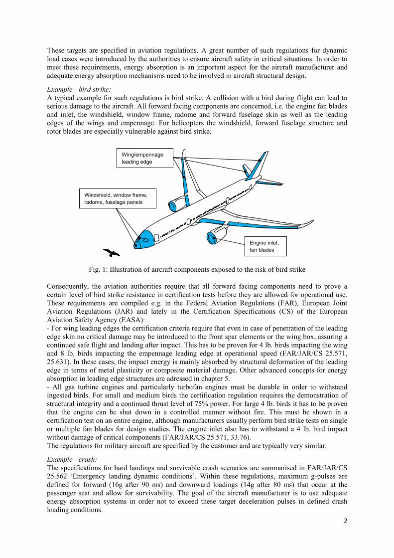
A typical example for such regulations is bird strike. A collision with a bird during flight can lead to
serious damage to the aircraft. All forward facing components are concerned, i.e. the engine fan blades
and inlet, the windshield, window frame, radome and forward fuselage skin as well as the leading
edges of the wings and empennage. For helicopters the windshield, forward fuselage structure and
rotor blades are especially vulnerable against bird strike.
Fig. 1: Illustration of aircraft components exposed to the risk of bird strike
Consequently, the aviation authorities require that all forward facing components need to prove a
certain level of bird strike resistance in certification tests before they are allowed for operational use.
These requirements are compiled e.g. in the Federal Aviation Regulations (FAR), European Joint
Aviation Regulations (JAR) and lately in the Certification Specifications (CS) of the European
Aviation Safety Agency (EASA):
- For wing leading edges the certification criteria require that even in case of penetration of the leading
edge skin no critical damage may be introduced to the front spar elements or the wing box, assuring a
continued safe flight and landing after impact. This has to be proven for 4 lb. birds impacting the wing
and 8 lb. birds impacting the empennage leading edge at operational speed (FAR/JAR/CS 25.571,
25.631). In these cases, the impact energy is mainly absorbed by structural deformation of the leading
edge in terms of metal plasticity or composite material damage. Other advanced concepts for energy
absorption in leading edge structures are adressed in chapter 5.
- All gas turbine engines and particularly turbofan engines must be durable in order to withstand
ingested birds. For small and medium birds the certification regulation requires the demonstration of
structural integrity and a continued thrust level of 75% power. For large 4 lb. birds it has to be proven
that the engine can be shut down in a controlled manner without fire. This must be shown in a
certification test on an entire engine, although manufacturers usually perform bird strike tests on single
or multiple fan blades for design studies. The engine inlet also has to withstand a 4 lb. bird impact
without damage of critical components (FAR/JAR/CS 25.571, 33.76).
The regulations for military aircraft are specified by the customer and are typically very similar.
Example - crash:
The specifications for hard landings and survivable crash scenarios are summarised in FAR/JAR/CS
25.562 ‘Emergency landing dynamic conditions’. Within these regulations, maximum g-pulses are
defined for forward (16g after 90 ms) and downward loadings (14g after 80 ms) that occur at the
passenger seat and allow for survivability. The goal of the aircraft manufacturer is to use adequate
energy absorption systems in order not to exceed these target deceleration pulses in defined crash
loading conditions.
Wing/empennage
leading edge
Windshield, window frame,
radome, fuselage panels
Engine inlet,
fan blades
3
Besides these specific requirements, some further general regulations apply to the structural design in
terms of damage tolerance. Certain levels of residual strength or structural integrity need to be
maintained after the occurrence of the damaging load case. For example, the 2-bay-crack criterion
states that even in case of damage or crack spanning the distance of two frame bays of a commercial
airliner, structural integrity needs to be maintained to ensure safe landing.
When developing energy absorbers for aircraft applications, further requirements are important
besides the sole achievement of the targeted, specific performance. Weight is a key factor in aircraft
design, and all developed absorber concepts need to be as lightweight as possible. Cost efficiency,
slightly less important in the past, is at eye level with weight efficiency today and also a main factor.
Furthermore, fatigue, maintenance, repair, reproducibility and robustness against changing loading
conditions are important criteria as well to distinguish different absorber systems and to select the
appropriate solution.
3. Energy-absorbing materials and structures
When it comes to energy absorption in a dynamic load case, two general options are possible for
structural design and structural performance. Either the energy is absorbed directly by the aircraft
structure by ductile deformation through the selection of appropriate skin materials (e.g. thermoplastic
composites made of glass fibre/PPS in the wing leading edge of Airbus A340 and A380, or general
metallic ductility in past wing or fuselage skins) or the energy is absorbed by separate energy absorber
elements, which typically do not carry any static loads but are additional weight only for the
absorption load case (e.g. crash absorber elements in aircraft and helicopter floors).
In general, the absorbed energy is represented by the area under the force-displacement curve as a
result of a compression or tensile test of any absorber material or structure. The weight-specific energy
absorption value in [kJ/kg] is often used to compare performance and weight benefits of absorber
concepts in lightweight design. An ideal absorber, consequently, shows a constant plateau stress level,
allowing for the maximum area under the curve. Most real absorbers, however, show initial load peaks
and oscillations, which ideally need to be reduced as much as possible. In aircraft design, the
following materials are typically used in existing absorber systems or absorber concepts:
Metals: energy absorption by yielding and plasticity. Typically aluminium, titanium or
eventually steel.
Fibre-reinforced composite materials: energy absorption by matrix cracking, delamination,
fibre fracture or crushing/fragmentation. Typically carbon, glass, quartz or aramid fibres with
epoxy or thermoplastic matrix.
Synthetic high-performance fibres: ultra-high-molecular-weight polyethylene (UHMWPE)
like Dyneema or Spectra with strength-to-weight ratios of about 8-15 times that of steel, in dry
or resin-infiltrated configuration, e.g. in vehicle armour or engine containments.
Many energy-absorbing structures for impact, crash or blast loads are based on cellular structures,
either used separately or in a sandwich configuration with face sheets. Their main benefit is their
extremely low weight and often ideal absorber-performance with nearly constant crushing load levels
for highest efficiency.
Honeycomb:
Hexagonal honeycomb structures are the state-of-the-art cellular structure for such applications. Made
either from Nomex, aluminium or thermoplastics like polypropylene, they can be found in numerous
aircraft applications. For example, the Airbus A380 uses about 4000 m² of honeycomb in its structural
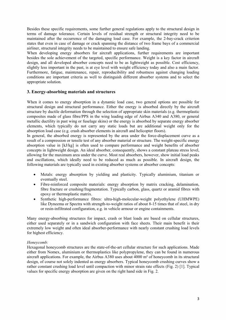
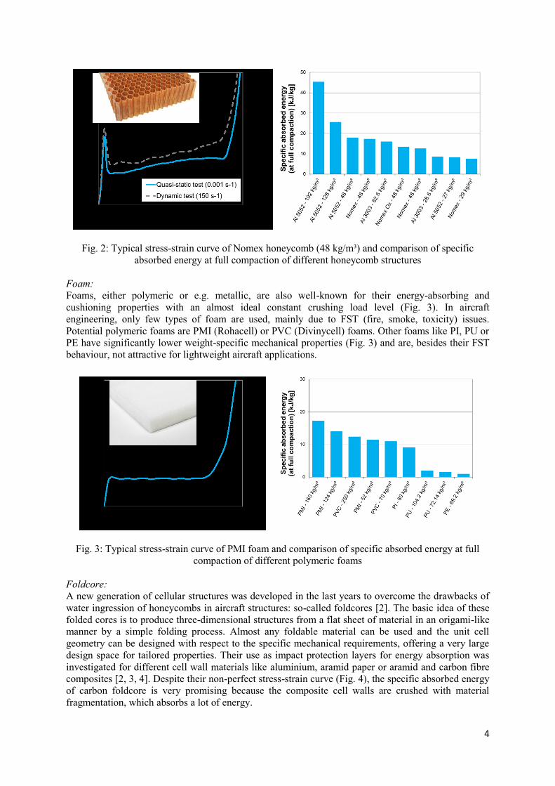
design, of course not solely indented as energy absorbers. Typical honeycomb crushing curves show a
rather constant crushing load level until compaction with minor strain rate effects (Fig. 2) [1]. Typical
values for specific energy absorption are given on the right hand side in Fig. 2.
4
Fig. 2: Typical stress-strain curve of Nomex honeycomb (48 kg/m³) and comparison of specific
absorbed energy at full compaction of different honeycomb structures
Foam:
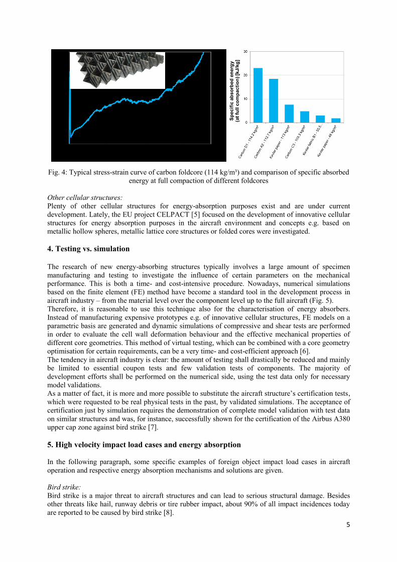
Foams, either polymeric or e.g. metallic, are also well-known for their energy-absorbing and
cushioning properties with an almost ideal constant crushing load level (Fig. 3). In aircraft
engineering, only few types of foam are used, mainly due to FST (fire, smoke, toxicity) issues.
Potential polymeric foams are PMI (Rohacell) or PVC (Divinycell) foams. Other foams like PI, PU or
PE have significantly lower weight-specific mechanical properties (Fig. 3) and are, besides their FST
behaviour, not attractive for lightweight aircraft applications.
Fig. 3: Typical stress-strain curve of PMI foam and comparison of specific absorbed energy at full
compaction of different polymeric foams
Foldcore:
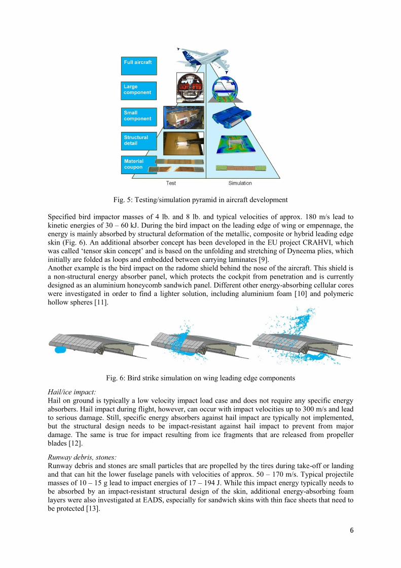
A new generation of cellular structures was developed in the last years to overcome the drawbacks of
water ingression of honeycombs in aircraft structures: so-called foldcores [2]. The basic idea of these
folded cores is to produce three-dimensional structures from a flat sheet of material in an origami-like
manner by a simple folding process. Almost any foldable material can be used and the unit cell
geometry can be designed with respect to the specific mechanical requirements, offering a very large
design space for tailored properties. Their use as impact protection layers for energy absorption was
investigated for different cell wall materials like aluminium, aramid paper or aramid and carbon fibre
composites [2, 3, 4]. Despite their non-perfect stress-strain curve (Fig. 4), the specific absorbed energy
of carbon foldcore is very promising because the composite cell walls are crushed with material
fragmentation, which absorbs a lot of energy.
5
Fig. 4: Typical stress-strain curve of carbon foldcore (114 kg/m³) and comparison of specific absorbed
energy at full compaction of different foldcores
Other cellular structures:
Plenty of other cellular structures for energy-absorption purposes exist and are under current
development. Lately, the EU project CELPACT [5] focused on the development of innovative cellular
structures for energy absorption purposes in the aircraft environment and concepts e.g. based on
metallic hollow spheres, metallic lattice core structures or folded cores were investigated.
4. Testing vs. simulation
The research of new energy-absorbing structures typically involves a large amount of specimen
manufacturing and testing to investigate the influence of certain parameters on the mechanical
performance. This is both a time- and cost-intensive procedure. Nowadays, numerical simulations
based on the finite element (FE) method have become a standard tool in the development process in
aircraft industry – from the material level over the component level up to the full aircraft (Fig. 5).
Therefore, it is reasonable to use this technique also for the characterisation of energy absorbers.
Instead of manufacturing expensive prototypes e.g. of innovative cellular structures, FE models on a
parametric basis are generated and dynamic simulations of compressive and shear tests are performed
in order to evaluate the cell wall deformation behaviour and the effective mechanical properties of
different core geometries. This method of virtual testing, which can be combined with a core geometry
optimisation for certain requirements, can be a very time- and cost-efficient approach [6].
The tendency in aircraft industry is clear: the amount of testing shall drastically be reduced and mainly
be limited to essential coupon tests and few validation tests of components. The majority of
development efforts shall be performed on the numerical side, using the test data only for necessary
model validations.
As a matter of fact, it is more and more possible to substitute the aircraft structure’s certification tests,
which were requested to be real physical tests in the past, by validated simulations. The acceptance of
certification just by simulation requires the demonstration of complete model validation with test data
on similar structures and was, for instance, successfully shown for the certification of the Airbus A380
upper cap zone against bird strike [7].
5. High velocity impact load cases and energy absorption
In the following paragraph, some specific examples of foreign object impact load cases in aircraft
operation and respective energy absorption mechanisms and solutions are given.
Bird strike:
Bird strike is a major threat to aircraft structures and can lead to serious structural damage. Besides
other threats like hail, runway debris or tire rubber impact, about 90% of all impact incidences today
are reported to be caused by bird strike [8].
6
Fig. 5: Testing/simulation pyramid in aircraft development
Specified bird impactor masses of 4 lb. and 8 lb. and typical velocities of approx. 180 m/s lead to
kinetic energies of 30 – 60 kJ. During the bird impact on the leading edge of wing or empennage, the
energy is mainly absorbed by structural deformation of the metallic, composite or hybrid leading edge
skin (Fig. 6). An additional absorber concept has been developed in the EU project CRAHVI, which
was called ‘tensor skin concept’ and is based on the unfolding and stretching of Dyneema plies, which
initially are folded as loops and embedded between carrying laminates [9].
Another example is the bird impact on the radome shield behind the nose of the aircraft. This shield is
a non-structural energy absorber panel, which protects the cockpit from penetration and is currently
designed as an aluminium honeycomb sandwich panel. Different other energy-absorbing cellular cores
were investigated in order to find a lighter solution, including aluminium foam [10] and polymeric
hollow spheres [11].
Fig. 6: Bird strike simulation on wing leading edge components
Hail/ice impact:
Hail on ground is typically a low velocity impact load case and does not require any specific energy
absorbers. Hail impact during flight, however, can occur with impact velocities up to 300 m/s and lead
to serious damage. Still, specific energy absorbers against hail impact are typically not implemented,
but the structural design needs to be impact-resistant against hail impact to prevent from major
damage. The same is true for impact resulting from ice fragments that are released from propeller
blades [12].
Runway debris, stones:
Runway debris and stones are small particles that are propelled by the tires during take-off or landing
and that can hit the lower fuselage panels with velocities of approx. 50 – 170 m/s. Typical projectile
masses of 10 – 15 g lead to impact energies of 17 – 194 J. While this impact energy typically needs to
be absorbed by an impact-resistant structural design of the skin, additional energy-absorbing foam
layers were also investigated at EADS, especially for sandwich skins with thin face sheets that need to
be protected [13].
7
Hydrodynamic ram:
Hydrodynamic ram is the pressure pulse in a fluid-filled tank after external excitation e.g. by a
penetrating projectile of e.g. 45 g with 560 m/s, leading to an energy of 7 kJ. This pressure pulse can
lead to serious damage of the tank structure [14]. Additional internal energy absorbers on the tank
walls were investigated to prevent from any structural damage, e.g. based on volume-filling foam,
self-sealing liners or energy-absorbing foam.
Tire rubber impact:
Impact of tire rubber after wheel failure can involve projectile masses of e.g. 2.45 kg, velocities of 64
m/s and a resulting kinetic energy of 5 kJ. Because of the hyperelastic behaviour of rubber, a
significant amount of strain energy is stored as elastic deformation of the projectile during impact
[15], making an impact-proof design with significant structural deformation typically sufficient,
without the use of additional energy absorbers against tire impact.
Rim release:
Rim release is referred to as the impact of a wheel rim fragment after fracture of the aircraft wheel
during take-off or landing. Aircraft wheels are typically made from forged aluminium alloy, such as
2014-T6, 2040-T6 or 7050-T74. During service they are exposed to harsh operating conditions, like
high take-off and landing loads, high-energy and high-temperature braking events or corrosion from
runway and aircraft fluids. The main cause of rim fracture is high-cycle fatigue loading with the
weakest area at the flange of the wheels. When wheel failure occurs, the fragments are often propelled
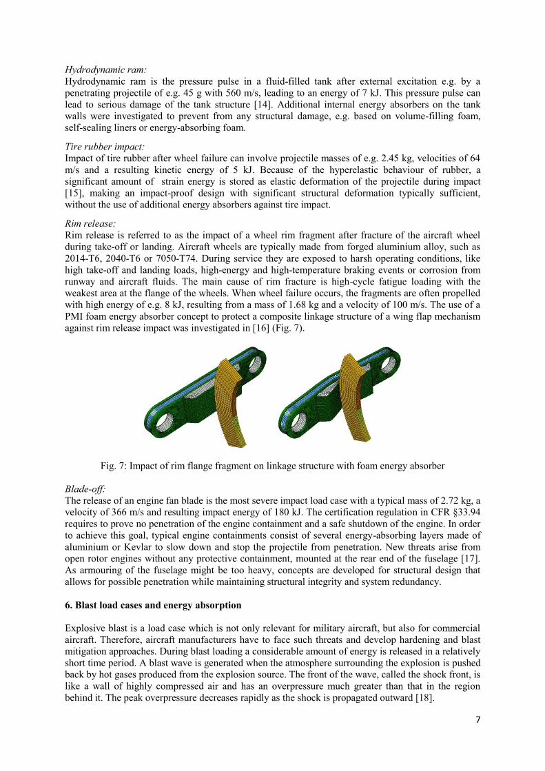
with high energy of e.g. 8 kJ, resulting from a mass of 1.68 kg and a velocity of 100 m/s. The use of a
PMI foam energy absorber concept to protect a composite linkage structure of a wing flap mechanism
against rim release impact was investigated in [16] (Fig. 7).
Fig. 7: Impact of rim flange fragment on linkage structure with foam energy absorber
Blade-off:
The release of an engine fan blade is the most severe impact load case with a typical mass of 2.72 kg, a
velocity of 366 m/s and resulting impact energy of 180 kJ. The certification regulation in CFR §33.94
requires to prove no penetration of the engine containment and a safe shutdown of the engine. In order
to achieve this goal, typical engine containments consist of several energy-absorbing layers made of
aluminium or Kevlar to slow down and stop the projectile from penetration. New threats arise from
open rotor engines without any protective containment, mounted at the rear end of the fuselage [17].
As armouring of the fuselage might be too heavy, concepts are developed for structural design that
allows for possible penetration while maintaining structural integrity and system redundancy.
6. Blast load cases and energy absorption
Explosive blast is a load case which is not only relevant for military aircraft, but also for commercial
aircraft. Therefore, aircraft manufacturers have to face such threats and develop hardening and blast
mitigation approaches. During blast loading a considerable amount of energy is released in a relatively
short time period. A blast wave is generated when the atmosphere surrounding the explosion is pushed
back by hot gases produced from the explosion source. The front of the wave, called the shock front, is
like a wall of highly compressed air and has an overpressure much greater than that in the region
behind it. The peak overpressure decreases rapidly as the shock is propagated outward [18].
8
For the aircraft manufacturer, the following blast load cases are relevant:
External blast by explosive warhead:
Mainly relevant for military aircraft, the direct attack by a rocket with explosive warhead has
disastrous consequences. Air-to-air missiles, man-portable air-defence systems (MANPADS) and
rocket-propelled grenades (RPG) are the main threats, using warheads with blast charges, hollow
charges or fragment charges. It is virtually impossible to develop an energy absorbing concept or
armour to withstand all of these attacks, the additional weight would make it impossible for the
aircraft to fly. Therefore, more efforts are put into hit avoidance like warning systems, flares,
defensive jammers or rapid flight manoeuvres.
Rocket motor blast:
This blast load is generated when a missile is launched from a helicopter or fighter aircraft and the
blast pressure from the igniting rocket motor hits the aircraft surface. Since this event typically occurs
regularly after each missile launch, no typical single-use absorbers are utilised but the structural design
needs to be strong enough to withstand this pressure loading.
Internal blast by improvised explosive device:
In times of terrorist attacks, bombing in commercial aircraft is a present threat that first occurred in the
1950s. Plastic explosives like C-4 or PETN were often used and hidden in luggage, parcels, carry-on
baggage, shoe soles, etc. In the last decades, significant progress was achieved to implement blast-
mitigating structures against such attacks. Blast-resistant luggage containers either based on
aluminium/glass fibre hybrid structures or high-performance textiles were developed in [19, 20].
Hardening measures and protective linings against explosive loading for the main fuselage are also
under investigation, with concepts e.g. based on blast-resistant sandwich panels [21, 22], elastomeric
polyurea coating or aluminium/glass fibre hybrid lay-ups with layers of Kevlar-reinforced elastomers
[23].
7. Crash load cases and energy absorption
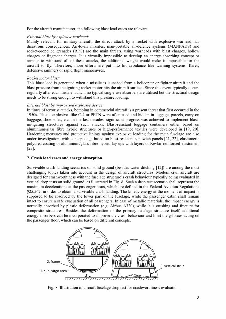
Survivable crash landing scenarios on solid ground (besides water ditching [12]) are among the most
challenging topics taken into account in the design of aircraft structures. Modern civil aircraft are
designed for crashworthiness with the fuselage structure’s crash behaviour typically being evaluated in
vertical drop tests on solid ground, as illustrated in Fig. 8. Such a drop test scenario shall represent the
maximum decelerations at the passenger seats, which are defined in the Federal Aviation Regulations
§25.562, in order to obtain a survivable crash landing. The kinetic energy at the moment of impact is
supposed to be absorbed by the lower part of the fuselage, while the passenger cabin shall remain
intact to ensure a safe evacuation of all passengers. In case of metallic materials, the impact energy is
normally absorbed by plastic deformation (e.g. Airbus A320), while it is crushing and fracture for
composite structures. Besides the deformation of the primary fuselage structure itself, additional
energy absorbers can be incorporated to improve the crash behaviour and limit the g-forces acting on
the passenger floor, which can be based on different concepts.
Fig. 8: Illustration of aircraft fuselage drop test for crashworthiness evaluation
3. vertical strut 2. frame
1. sub-cargo area
9
Energy absorber in sub-cargo area:
In the chain of energy absorption, the sub-cargo area in the lower fuselage part is loaded first as it first
comes into contact with the ground. A lot of research was conducted e.g. in the EU project CRASURV
with respect to composite sine wave beams in the subfloor structure that are crushed under vertical
crash loads [24, 25]. Further concepts are based on foam [26] or honeycomb absorbers in the subfloor
structure [27].
Energy absorber in frame:
Additional energy absorbers or plastic hinges can also be integrated in the circumferential frames of
the fuselage [28], as the frame typically breaks at a location close to the attachment of the vertical
struts.
Energy absorber in vertical strut:
The third option includes energy absorbers in the vertical z-struts of the fuselage. Z-struts are the
connection of passenger floor and lower frames, acting as the support in vertical (z-) direction. In the
crash case, they are loaded in axial compression as soon as the lower fuselage part is flattened. In [29],
a lightweight composite crash absorber element was developed for integration into the vertical struts,
which absorbs energy under compression loads by cutting the composite strut into stripes and crushing
the material under bending.
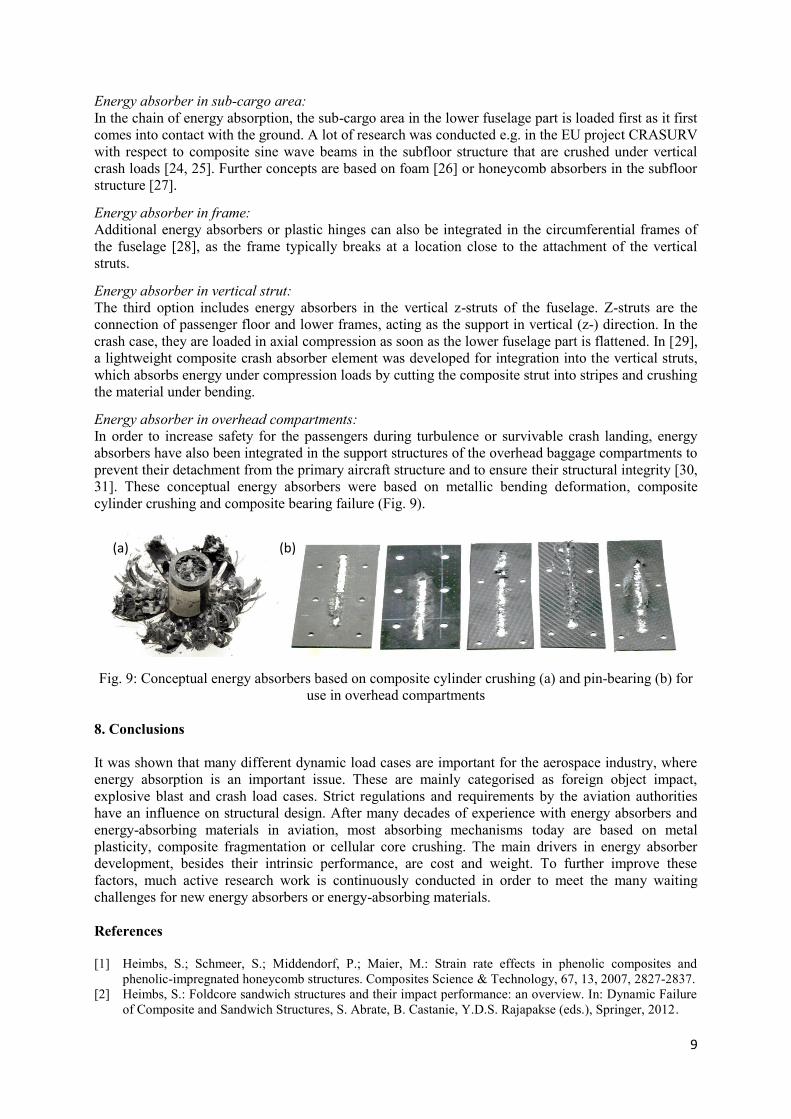
Energy absorber in overhead compartments:
In order to increase safety for the passengers during turbulence or survivable crash landing, energy
absorbers have also been integrated in the support structures of the overhead baggage compartments to
prevent their detachment from the primary aircraft structure and to ensure their structural integrity [30,
31]. These conceptual energy absorbers were based on metallic bending deformation, composite
cylinder crushing and composite bearing failure (Fig. 9).
Fig. 9: Conceptual energy absorbers based on composite cylinder crushing (a) and pin-bearing (b) for
use in overhead compartments
8. Conclusions
It was shown that many different dynamic load cases are important for the aerospace industry, where
energy absorption is an important issue. These are mainly categorised as foreign object impact,
explosive blast and crash load cases. Strict regulations and requirements by the aviation authorities
have an influence on structural design. After many decades of experience with energy absorbers and
energy-absorbing materials in aviation, most absorbing mechanisms today are based on metal
plasticity, composite fragmentation or cellular core crushing. The main drivers in energy absorber
development, besides their intrinsic performance, are cost and weight. To further improve these
factors, much active research work is continuously conducted in order to meet the many waiting
challenges for new energy absorbers or energy-absorbing materials.
References
[1] Heimbs, S.; Schmeer, S.; Middendorf, P.; Maier, M.: Strain rate effects in phenolic composites and
phenolic-impregnated honeycomb structures. Composites Science & Technology, 67, 13, 2007, 2827-2837.
[2] Heimbs, S.: Foldcore sandwich structures and their impact performance: an overview. In: Dynamic Failure
of Composite and Sandwich Structures, S. Abrate, B. Castanie, Y.D.S. Rajapakse (eds.), Springer, 2012.
(a) (b)
10
[3] Fischer, S.; Drechsler, K.: Aluminium foldcores for sandwich structure application. CELLMET2008,
Cellular Metals for Structural and Functional Applications, International Symposium, Dresden, 2008.
[4] Heimbs, S.; Cichosz, J.; Klaus, M.; Kilchert, S.; Johnson, A.F.: Sandwich structures with textile-reinforced
composite foldcores under impact loads. Composite Structures, 92, 6, 2010, 1485-1497.
[5] Johnson, A.: Novel structural core sandwich materials for aircraft applications: CELPACT project
overview. SAMPE Europe International Conference (SEICO-09), Paris, 2009.
[6] Heimbs, S.: Virtual testing of sandwich core structures using dynamic finite element simulations.
Computational Materials Science, 45, 2, 2009, 205-216.
[7] Faure, J.M.: Airbus dynamic analysis experiences using Abaqus/Explicit. 2011 SIMULIA Customer
Conference, Barcelona, 2011.
[8] Heimbs, S.: Computational methods for bird strike simulations: a review. Computers & Structures, 89, 23-
24, 2011, 2093-2112.
[9] Kermanidis, T.; Labeas, G.; Sunaric, M.; Ubels, L.: Development and validation of a novel bird strike
resistant composite leading edge structure. Applied Composite Materials, 12, 6, 2005, 327-353.
[10] Hanssen, A.G.; Girard, Y.; Olovsson, L.; Berstad, T.; Langseth, M.: A numerical model for bird strike of
aluminium foam-based sandwich panels. International Journal of Impact Engineering, 32, 7, 2006, 1127-1144
[11] Zeng, H.B.; Pattofatto, S.; Zhao, H.; Girard, Y.; Fascio, V.: Perforation of sandwich plates with graded
hollow sphere cores under impact loading. International Journal of Impact Engineering, 37, 2010, 1083-1091.
[12] Perez, J.L.; Benitez, L.H.; Oliver, M.; Climent, H.: Survey of aircraft structural dynamics nonlinear
problems and some recent solutions. The Aeronautical Journal, 115, 1173, 2011, 653-668.
[13] Middendorf, P.: Composites - Materialmodellierung und Anwendungen im Flugzeugbau. 3rd LS-DYNA
Forum, Bamberg, 2004.
[14] Stephani, P.; Middendorf, P.; Less, C.: Numerical analysis of the hydrodynamic ram of a CFRP integral
tank. In: Structures Under Shock and Impact IX, N. Jones (ed.), WIT Press, 2006, 45-55.
[15] Heimbs, S.; Van Den Broucke, B.; Duplessis Kergomard, Y.; Dau, F.; Malherbe, B.: Rubber impact on 3D
textile composites. Applied Composite Materials, 19, 3-4, 2012, 275-295.
[16] Heimbs, S.; Lang, H.; Havar, T.: Rim release analysis: impact of aircraft wheel flange fragment on wing
flap mechanism. In: Structures Under Shock and Impact XII, N. Jones, C.A. Brebbia (ed.), WIT Press, 2012.
[17] Saucray, J.M.: Structural vulnerability problematic overview for future smart fixed wing counter rotating
open rotor aircraft. Workshop on Dynamic Failure of Composite and Sandwich Structures, Toulouse, 2011.
[18] Beshara, F.B.A.: Modelling of blast loading on aboveground structures - I. general phenomenology and
external blast. Computers & Structures, 51, 5, 1994, 585-596.
[19] Fleisher, H.J.: Design and explosive testing of a blast-resistant luggage container. In: Structures Under
Shock and Impact IV, C. A. Brebbia, N. Jones, A.J. Watson (eds.), WIT Press, 1996, 51-60.
[20] Zangani, D.; Ambrosetti, S.; Franitza, P.; Illing-Guenther, H.; Koenig, R.P.: Development of a novel
concept of explosion-resistant cargo container for narrow-body aircrafts. ICAS 2010, 27th International
Congress of the Aeronautical Sciences, Nice, 2010.
[21] Thompson, S.C.; Muchnick, H.; Choi, H.J.; McDowell, D.; Allen, J.K.; Mistree, F.: Robust materials
design of blast resistant panels. 11th AIAA/ISSMO Multidisciplinary Analysis and Optimization
Conference, Portsmouth, VA, 2006.
[22] Wang, E.; Gardner, N.; Shukla, A.: The blast resistance of sandwich composites with stepwise graded
cores. International Journal of Solids and Structures, 46, 18-19, 2009, 3492-3502.
[23] Veldman, R.L.; Ari-Gur, J.; Panaggio, M.: Lightweight mitigating materials for structures under close-in
blast loading. 50th AIAA/ASME/ASCE/AHS/ASC Structures, Structural Dynamics, and Materials
Conference, Palm Springs, CA, 2009.
[24] Kindervater, C.M.; Georgi, H.: Composite strength and energy absorption as an aspect of structural crash
resistance. In: Structural Crashworthiness and Failure, N. Jones, T. Wierzbicki (ed.), Elsevier, 1993, 189-235.
[25] Arnaudeau, F.; Deletombe, E.; Mahe, M.; Le Page, F.: Crashworthiness of aircraft composites structures.
ASME International Mechanical Engineering Congress & Exposition, New Orleans, LA, 2002.
[26] Fasanella, E.L.; Jackson, K.E.; Sparks, C.E.; Sareen, A.K.: Water impact test and simulation of a composite
energy absorbing fuselage section. American Helicopter Society 59th Annual Forum, Phoenix, AZ, 2003.
[27] Meng, F.X.; Zhou, Q.; Yang, J.L.: Improvement of crashworthiness behaviour for simplified structural
models of aircraft fuselage. International Journal of Crashworthiness, 14, 1, 2009, 83-97.
[28] Woodson, M.B.; Johnson, E.R.; Haftka, R.T.: Optimal design of composite fuselage frames for
crashworthiness. International Journal of Crashworthiness, 1, 4, 1996, 369-380.
[29] Heimbs, S.; Strobl, F.; Middendorf, P.: Integration of a composite crash absorber in aircraft fuselage
vertical struts. International Journal of Vehicle Structures & Systems, 3, 2, 2011, 87-95.
[30] Heimbs, S.; Vogt, D.; Hartnack, R.; Schlattmann, J.; Maier, M.: Numerical simulation of aircraft interior
components under crash loads. International Journal of Crashworthiness, 13, 5, 2008, 511-521.
[31] Pein, M.; Krause, D.; Heimbs, S.; Middendorf, P.: Innovative energy-absorbing concept for aircraft cabin
interior. AST 2007, International Workshop on Aircraft System Technologies, Hamburg, 2007.