Embed Size (px)
Citation preview
Energy &Environmental Science
REVIEW
Publ
ishe
d on
13
Sept
embe
r 20
13. D
ownl
oade
d by
Im
peri
al C
olle
ge L
ondo
n L
ibra
ry o
n 09
/10/
2013
15:
04:4
4.
View Article OnlineView Journal
aDepartment of Chemical Engineering, Imp
London, SW7 2AZ, UK. E-mail: p.fennell@imbInstituto Nacional del Carbon, (CSIC), FrancEnergy and Resource Technology Centre,
MK43 0AL, UKdDepartment of Earth Science and Engine
Kensington, London, SW7 2AZ, UKeSCCS Centre, School of Engineering, Th
Buildings, Edinburgh EH9 3JL, UKfCentre for Environmental Policy, Imperial C
SW7 2AZ, UKgDepartment of Chemistry, Imperial College
2AZ, UKhSCCS, School of Geosciences, The Univer
Edinburgh EH9 3JW, UKiChalmers University of Technology, 412 96jEnergy Technology and Innovation InitiativkSchool of Process, Environmental and Ma
Leeds LS2 9JT, UKlMcKetta Department of Chemical Enginee
Austin, TX 78712, USA
Cite this: DOI: 10.1039/c3ee42350f
Received 12th July 2013Accepted 13th September 2013
DOI: 10.1039/c3ee42350f
www.rsc.org/ees
This journal is ª The Royal Society of
Carbon capture and storage update
Matthew E. Boot-Handford,a Juan C. Abanades,b Edward J. Anthony,c
Martin J. Blunt,d Stefano Brandani,e Niall Mac Dowell,a Jose R. Fernandez,b
Maria-Chiara Ferrari,e Robert Gross,f Jason P. Hallett,g R. Stuart Haszeldine,h
Philip Heptonstall,f Anders Lyngfelt,i Zen Makuch,f Enzo Mangano,e
Richard T. J. Porter,j Mohamed Pourkashanian,k Gary T. Rochelle,l Nilay Shah,a
Joseph G. Yaoa and Paul S. Fennell*a
In recent years, Carbon Capture and Storage (Sequestration) (CCS) has been proposed as a potential method
to allow the continued use of fossil-fuelled power stations whilst preventing emissions of CO2 from reaching
the atmosphere. Gas, coal (and biomass)-fired power stations can respond to changes in demandmore readily
thanmany other sources of electricity production, hence the importance of retaining them as an option in the
energy mix. Here, we review the leading CO2 capture technologies, available in the short and long term, and
their technological maturity, before discussing CO2 transport and storage. Current pilot plants and
demonstrations are highlighted, as is the importance of optimising the CCS system as a whole. Other topics
briefly discussed include the viability of both the capture of CO2 from the air and CO2 reutilisation as
climate change mitigation strategies. Finally, we discuss the economic and legal aspects of CCS.
1. Introduction
This paper discusses Carbon Capture and Storage (CCS), as onemethod to mitigate climate change. This paper will not assessthe science behind anthropogenic climate change, the over-whelming evidence is presented by publications such as.1 Therationale for deployment of CCS on fossil-fuelled power stations(and possibly in the future with biomass-red stations) is that,when deployed in conjunction with other technologies (such asrenewables and nuclear), the overall cost of electricity supply is
erial College London, South Kensington,
perial.ac.uk; Tel: +44 (0)20 7594 6637
cisco Pintado Fe 26, 33011 Oviedo, Spain
Craneld University, Craneld, Bedford,
ering, Imperial College London, South
e University of Edinburgh, The King's
ollege London, South Kensington, London,
London, South Kensington, London, SW7
sity of Edinburgh, The King's Buildings,
Goteborg, Sweden
e, University of Leeds, Leeds, LS2 9JT, UK
terials Engineering, University of Leeds,
ring, The University of Texas at Austin,
Chemistry 2013
minimised. This is because fossil-fuelled power stations areable to vary their output in response to changes in demand (orindeed to the supply from intermittent sources such as wind)and thus CCS reduces the need for large-scale energy storage tobe developed.
Carbon capture and storage refers to a number of technol-ogies which capture CO2 at some stage from processes such ascombustion (most generally for power generation) or gasica-tion. Many industrial processes, most notably cement manu-facture, iron and steel making and natural gas treatmentalso intrinsically produce CO2 and can be tted with CO2
capture technologies (and for these industries, CCS offers one ofthe very few remaining methods to reduce CO2 emissions wherethe best available technology in terms of e.g. energy efficiency isalready used). The captured CO2 is then pressurised to�100 bar(or more), prior to being transported to a storage site, where it isinjected into one of a number of types of stable geologicalfeatures, trapping it for multiple hundreds or thousands ofyears and preventing its subsequent emission into the atmo-sphere. All of the individual components of the CCS chain, fromcapture all the way through to (and including) storage, havebeen demonstrated at or close to industrial scale. However,their integration into a single process is a signicant (but ulti-mately solvable) engineering challenge. There are a largenumber of different technologies for CCS, some closer todeployment than others. The purpose of this paper is to reviewthe most recent developments in the eld, and not to introducethe topics. The interested reader is referred to a previous review,and a special edition of this journal for introductory material.2,3
Energy Environ. Sci.
Energy & Environmental Science Review
Publ
ishe
d on
13
Sept
embe
r 20
13. D
ownl
oade
d by
Im
peri
al C
olle
ge L
ondo
n L
ibra
ry o
n 09
/10/
2013
15:
04:4
4.
View Article Online
Here, we discuss solvent scrubbing, oxyfuel combustion (forboth pulverised fuel and in a uidised bed), chemical loopingand calcium looping, together with low-temperature sorbents,as exemplars of CCS technologies which might be commer-cialised within 10–20 years, (solvent scrubbing and oxyfuelpotentially being commercialised towards the beginning of theperiod, with the other technologies towards the end, though wehave included ionic liquids as a natural adjunct to solventscrubbing even though these solvents are unlikely to be com-mercialised within 20 years). Of course, there are other tech-nologies (such as membranes) which could also be considered,but are not covered here. We then move on to discuss a numberof technologies that are either more niche or are further awayfrom commercialisation (CO2 utilisation through mineralisa-tion or in direct production of useful products). Transport ofCO2 is then discussed, prior to storage. We then discuss thecritical overarching themes: systems integration and policydesign and implications for investment.
Throughout this paper, where efficiency penalties arequoted, it should be noted that they are relative to a powerstation which will have an underlying thermal efficiency ofbetween �40 and 60%. This means that an efficiency penalty of(say) 5% requires an increase in fuel-burn of �10% in order toproduce the same amount of electricity.
1.1 Current power generation
Despite recent global economic turmoil leading to appreciablereductions in global demand for oil and gas, demand for coalhas if anything signicantly increased in the period since 2005.In 2010, world coal demand was approximately 5000 milliontonnes of coal equivalent (Mtce). Under the IEA's “CurrentPolicies Scenario”, this is projected to grow to 7500 Mtce by2035. It is worth noting that the entirety of this growth (in allscenarios) occurs in non-OECD countries. The share of globalcoal market arising from the non-OECD countries is expected torise from 66% to 82%.4
Power generation is heavily dependent on coal-red plantsthroughout the world; in 2008, 41% of total global electricitywas obtained by coal combustion (corresponding to 8273 TWh).While this share is expected to drop to 32% by 2035 (corre-sponding to 11 200 TWh), coal remains the dominant source ofenergy globally, with non-OECD demand doubling in the periodto 2035. OECD demand for coal is expected to drop by as muchas 33%—a result of a renewed “dash-for-gas” arising from theexploitation of reserves of shale gas (and other unconventionalsources) and policies encouraging the reduction of the carbonintensity of power generation.4 Conventional or so called “sub-critical” coal-red power generating plants operate with lowthermal efficiency (30–45%), which in turn incurs signicantfuel costs. This large fuel requirement will in turn increaseexposure to fuel price volatility, thus increasing the investmentrisk associated with this technology. For these reasons, sub-critical power plants are expected to displaced by super-criticaland ultra-supercritical power plants, reducing their marketshare from 73% in 2008 to 31% in 2035.4 Super-criticalpower plants are considered to be a promising option for future
Energy Environ. Sci.
coal-based power generation as they operate with higher base-load efficiency – in the range of 48–52%.5 Super-critical powerplants operate with steam parameters in range of 240 bar/600 �Cand ultra-super critical plants which operate in the range of350 bar/700 �C/720 �C or higher are under development.
However, owing to the relatively high-priced materialsrequired for their construction, the capital cost associated withsupercritical power plants is relatively high6,7 and this is anactive area of on-going research.
For example, Yamamoto et al.8 reported the application ofheat resistant material of high creep rupture strength andhigh oxidation resistance up to 650 �C, which have alreadybeen developed for boilers and turbines of ultra-supercriticalpower plants. Viswanathan5 discussed the materials for ultra-supercritical (USC) plants to withstand operating steamconditions up to 760 �C temperature and 35 MPa pressure,which are under development.
2. Developments in amine scrubbing2.1 Thermodynamic context
CO2 capture by post-combustion chemisorption relies on theseparation of CO2 from ue gas using a chemical solvent. Thus,the thermophysical properties are of paramount importance indetermining the potential of absorption, as it species interfa-cial phase equilibrium in addition to speciation in liquid phaseand the enthalpy of absorption. Consequently, appropriateselection of a physical property model is of prime importance forthe correct modelling of CO2 capture processes.
In the context of CO2 capture, aqueous alkanolamine solu-tions are an extremely complex solution of molecular species,electrolyte species and reaction products and, on certain timescales, reaction intermediates. The physical property modelmust be applicable to all phases and chemical equilibria for awide range of thermodynamic states. Several thermodynamicmodels have been used in the literature to represent theabsorption of acid gases in alkanolamine solution, and they canbe classied as one of three types: empirical models, equationof state approaches and excess Gibbs energy approaches.
Empirical models are based on empirical mathematicalrelations, rather than theoretical considerations. Vapour-liquidequilibria (VLE) and chemical equilibria are represented inthese models by tting numerical parameters on experimentaldata. The resulting correlations, such as that of Gabrielsenet al.9 for the partial pressure of CO2 as a function of the liquidphase CO2 loading, are oen easy to implement. However, aswith all correlations, owing to their lack of theoretical under-pinning, they are typically unsuitable for predictive calculationor extrapolation.
Equations of state can be used to represent both liquid phaseand gas phases (including electrolytes). Heterogeneousapproaches, using the excess Gibbs energy to obtain activitycoefficients in the liquid phase. These models typically need tobe coupled with a separate model to describe the gas phase; thisis oen a cubic equation of state. Homogeneous approaches arebased on the Helmholtz energy; such as the formulation ofFurst and Renon.10,11 Recently, the Statistical Associating Fluid
This journal is ª The Royal Society of Chemistry 2013
Review Energy & Environmental Science
Publ
ishe
d on
13
Sept
embe
r 20
13. D
ownl
oade
d by
Im
peri
al C
olle
ge L
ondo
n L
ibra
ry o
n 09
/10/
2013
15:
04:4
4.
View Article Online
Theory12,13 (SAFT) for potentials of variable range14 (SAFT-VR)has been applied to aqueous mixtures of amines15 and alka-nolamines16,17 and CO2. This new approach provides an implicittreatment of the chemical reactions and ionic speciation inthese complex mixtures. Importantly, although the reactionproducts are also treated in an implicit fashion, it is possible toobtain an accurate description of the equilibrium carbamate/bicarbonate products.17 As a consequence, when these ther-modynamic models were incorporated in process models3,18 itwas not necessary to describe the reaction products in theprocess model, nor was an enhancement factor required todescribe the accelerating effect of the reactions on the masstransfer. This had the effect of signicantly reducing the size ofthe process models and consequently it was possible to usethese detailed dynamic, non-equilibrium models to performoptimisation19 and control20 studies. It is noteworthy that theSAFT approach has been coupled with classical density func-tional theory approaches and has been used to predict vapour–liquid interfacial properties21 and the so-SAFT variant22 hasalso been used to describe the thermophysical properties andphase behaviour of ionic liquids in the context of CO2 capture.23
The third class of models uses the excess Gibbs energy tocompute activity coefficients; they are oen based on already-existing models for nonelectrolyte systems and extended withthe Debye–Huckel theory to address electrolyte species. Themodel by Deshmukh andMather24 is one of the simpler models,and parameters have been regressed for some amines25 itassumes ideality for water and calculates the activity coefficientfor diluted species with a virial term for interaction betweenspecies. The model by Pitzer26 is quite similar and has beenused to represent the solubility of CO2 in aqueous methyl-diethanolamine (MDEA) and piperazine (PZ).27 Among the moreelaborated models using the local composition of the mixture,the electrolyte-NRTL (e-NRTL) and extended UNIQUAC (e-UNI-QUAC) models prevail. The e-NRTL model28,29 has been exten-sively used for CO2 absorption characterisation.30,31 Theextended UNIQUAC32 provides the same theoretical basis ase-NRTL, with a simpler formulation, and it has already provedits ability to represent the alkanolamine system for CO2
absorption.33
The development of amine scrubbing has been focused onits application to coal-red power plants. Unless otherwisenoted, the data and discussion on amine scrubbing thatfollows are based on the application to coal-red powerplants. However, amine scrubbing should be useful for otherapplications.
2.2 Process owsheet
The process technology using 30 wt% monoethanolamine(MEA) that has been evaluated by NETL34 to give a baseline forthe solvent scrubbing process can no longer be used as arepresentative baseline for post-combustion capture. A numberof vendors, including Fluor35 and MHI36 have developedprocesses and completed evaluations that give energy perfor-mances substantially better than that reported in the NETLanalyses. In addition, a recent paper by Ahn et al. has illustrated
This journal is ª The Royal Society of Chemistry 2013
all the different types of owsheet congurations for the aminescrubbing process.37
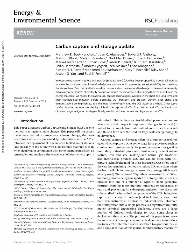
Fig. 1 gives an example of a second generation, optimisedprocess for CO2 capture by amine scrubbing using 8 molal (m)piperazine (PZ).38,39 Compared to 30 wt% MEA it has twice therate of CO2 absorption, 1.8 times the intrinsic working capacity,5 to 10% lower heat of absorption (a disadvantage), and amaximum stripper T/P of 150 �C/8 bar.40
In addition to the absorber, the process would probablyinclude SO2 polishing with sodium alkali scrubbing and directcontact cooling of the ue gas before the PZ absorber. It wouldalso usually include a water wash and aerosol removal aer theabsorber. Much of this additional ue gas contacting could beincorporated into the same vessel as the CO2 absorption.
2.3 Overall energy performance
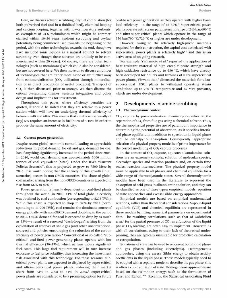
2.3.1 Reboiler heat duty. The measured and projectedreboiler heat duty for CO2 capture from coal-red power plantsby amine scrubbing has improved from as high as 5.5 MJtCO2
�1 in 2001 to as little as 2.6 in 2012 (Fig. 2). Early estimatesused 20 wt% (MEA) with a simple stripper and absorber.Current systems assume 35 or 40 wt% MEA or other advancedamines with interheated strippers and intercooled absorbers orother comparable process improvements. With a Carnot cycleanalysis, the minimum heat duty to separate 12% CO2 inue gas and produce pure CO2 at 1 bar is 1 MJ t�1. Therefore,the overall thermodynamic efficiency of the separation processis approaching 40%.
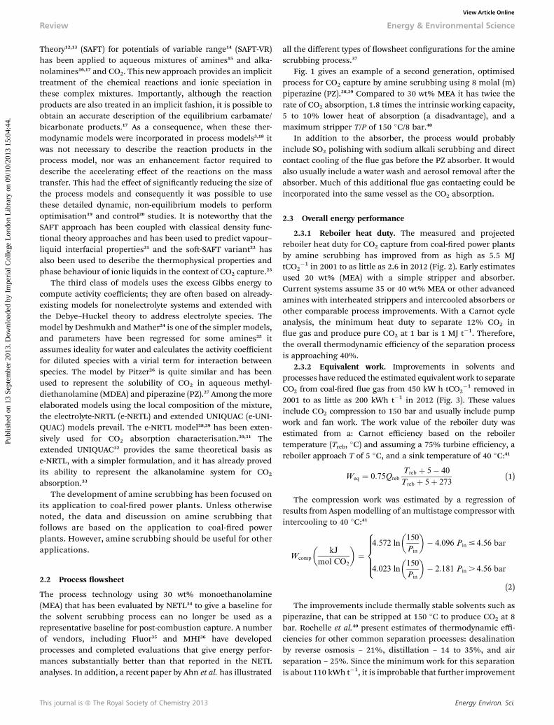
2.3.2 Equivalent work. Improvements in solvents andprocesses have reduced the estimated equivalent work to separateCO2 from coal-red ue gas from 450 kW h tCO2
�1 removed in2001 to as little as 200 kWh t�1 in 2012 (Fig. 3). These valuesinclude CO2 compression to 150 bar and usually include pumpwork and fan work. The work value of the reboiler duty wasestimated from a: Carnot efficiency based on the reboilertemperature (Treb, �C) and assuming a 75% turbine efficiency, areboiler approach T of 5 �C, and a sink temperature of 40 �C:41
Weq ¼ 0:75Qreb
Treb þ 5� 40
Treb þ 5þ 273(1)
The compression work was estimated by a regression ofresults from Aspen modelling of an multistage compressor withintercooling to 40 �C:41
Wcomp
�kJ
mol CO2
�¼
4:572 ln
�150
Pin
�� 4:096 Pin # 4:56 bar
4:023 ln
�150
Pin
�� 2:181 Pin . 4:56 bar
8>>><>>>:
(2)
The improvements include thermally stable solvents such aspiperazine, that can be stripped at 150 �C to produce CO2 at 8bar. Rochelle et al.40 present estimates of thermodynamic effi-ciencies for other common separation processes: desalinationby reverse osmosis – 21%, distillation – 14 to 35%, and airseparation – 25%. Since the minimum work for this separationis about 110 kWh t�1, it is improbable that further improvement
Energy Environ. Sci.
Fig. 1 Intercooled Absorber/Interheated stripper with 8 m PZ. Stripper bottom at 150�C/7.9 bar. Weq ¼ 30.5 kJ mol�1 CO2 ¼ 193 kW h per tonne CO2.
Fig. 2 Reboiler heat duty for amine scrubbing on coal-fired power plants, takenin part from Rochelle et al.40 MEA ¼ monoethanolamine, KS-1 ¼ proprietary MHIsolvent, PZ ¼ 40 wt% piperazine, H3 ¼ proprietary Hitachi solvent,568 LB1 ¼Proprietary BASF/Linde solvent/process,569 TS-1 ¼ proprietary Toshiba solvent.570
Fig. 3 The total energy requirement for amine scrubbing to separate CO2 fromcoal flue gas and produce it at 150 bar, taken in part from Rochelle et al. (2011).MEA ¼ monoethanolamine, KS-1 ¼ Proprietary MHI solvent, PZ ¼ 40 wt%piperazine, LB-2 ¼ case with Proprietary BASF/Linde process/solvent (Jovanovicet al., 2012).
Energy & Environmental Science Review
Publ
ishe
d on
13
Sept
embe
r 20
13. D
ownl
oade
d by
Im
peri
al C
olle
ge L
ondo
n L
ibra
ry o
n 09
/10/
2013
15:
04:4
4.
View Article Online
from the current thermodynamic efficiency of about 50% willcome easily. A typical coal-red power plant produces about1000 kWh tCO2
�1 emitted, so CO2 capture by amine scrubbingwill reduce the power output by 20 to 30%.
Energy Environ. Sci.
2.4 Features of second-generation processes
2.4.1 Absorber operating T and intercooling. In processesrelying upon temperature swing regeneration, the absorbershould be operated at as low a temperature as possible with theavailable heat sink to maximise the rich and lean loading of thesolvent. The design in Fig. 1 includes removing heat to 40 �C indirect contact cooling of the inlet ue gas, intercooling in themiddle of the absorber, and trim cooling of the lean solvent feedto the absorber.
2.4.2 Stripper operating T. In processes relying upontemperature swing regeneration, the stripper should be oper-ated at the maximum temperature allowed by solvent degra-dation or by the available heat supply. This maximises thepressure of the CO2 in the rst stage of the compressor. Elevatedstripper T also reduces the ratio of water vapour to CO2 in thesimple stripper overhead. The example uses reboiler conditionsof 150 �C and 8 bar.
Steam pressure should be reversibly reduced before it isused in the reboiler. In this example the steam pressure is 6bar and could be consistent with steam extracted between theintermediate and low pressure turbine stages of a typicalcoal-red power plant. The reboiler approach temperatureshould be minimised consistent with the tradeoff of reboilercapital cost and equivalent work loss, typically 5 to 10 K. Theequivalent work of the stripper and compressor systemshould be estimated from the work value of the steam heatand the compressor work to a nal pressure (typically150 bar) by equations such as those offered by Van Wagener(above).41
Effective cross exchange between the cold rich and hot leansolvent eliminates much of the energy cost of operating with alarge solvent rate. Plate-and-frame exchangers appear to permitan economic approach T of 5 K. A cold rich bypass41 can be usedto address imbalance between the heat capacities of the richand lean streams. With a typical working capacity of 0.8 molCO2 kg(H2O + amine)�1 and a heat capacity of 3.5 kJ K�1 kg(H2O+ amine)�1, the 5 K approach requires only 22 kJheat mol CO2
�1
or 3.5 to 4.4 kJequivalent work mol CO2�1 (with stripper at 120 to
150 �C).
This journal is ª The Royal Society of Chemistry 2013
Review Energy & Environmental Science
Publ
ishe
d on
13
Sept
embe
r 20
13. D
ownl
oade
d by
Im
peri
al C
olle
ge L
ondo
n L
ibra
ry o
n 09
/10/
2013
15:
04:4
4.
View Article Online
2.4.3 Advanced stripper conguration. A number ofstripper congurations are available to minimise the loss ofheat as water vapour. The interheated stripper is the bestof these (Fig. 3).41 Other congurations that work almost as wellinclude adiabatic ash with compression,41 cold rich bypass,41
matrix,42 two-stage heated ash,41 and multipressure.43 Theinterheated stripper uses 10 to 20% less energy than a simplestripper.38 With an interheated stripper, less than 20% ofthe overhead vapour is water. Therefore, anhydrous solvents orsorbents will not signicantly reduce the heat requirement byavoiding the vaporisation of water.
2.4.4 Reversible stripping. When the lean loading (orsolvent ow rate) is optimised to minimise energy consump-tion, there is a tradeoff of sensible heat loss at high solvent rate(high lean loading) and stripping steam use at low solventrate (low lean loading). With a close exchanger approach T (5 K),the stripper typically only removes enough CO2 from the richsolvent to leave the maximum lean loading that allows foradequate CO2 removal.40 An intercooled absorber using asolvent with a fast rate of CO2 absorption (such as 8 m PZ)should be able to achieve 90% CO2 removal with a lean loadingthat gives an equilibrium CO2 partial pressure of 0.5 kPa at 40�C and a rich loading that gives an equilibrium CO2 partialpressure of 5 kPa at 40 �C.44 Therefore, the difference betweenthe CO2 loading at these rich (5 kPa CO2 at 40 �C) and lean(0.5 kPa at 40 �C) conditions will give a useful estimate of theworking capacity of the solution.
2.5 Solvent selection for energy performance
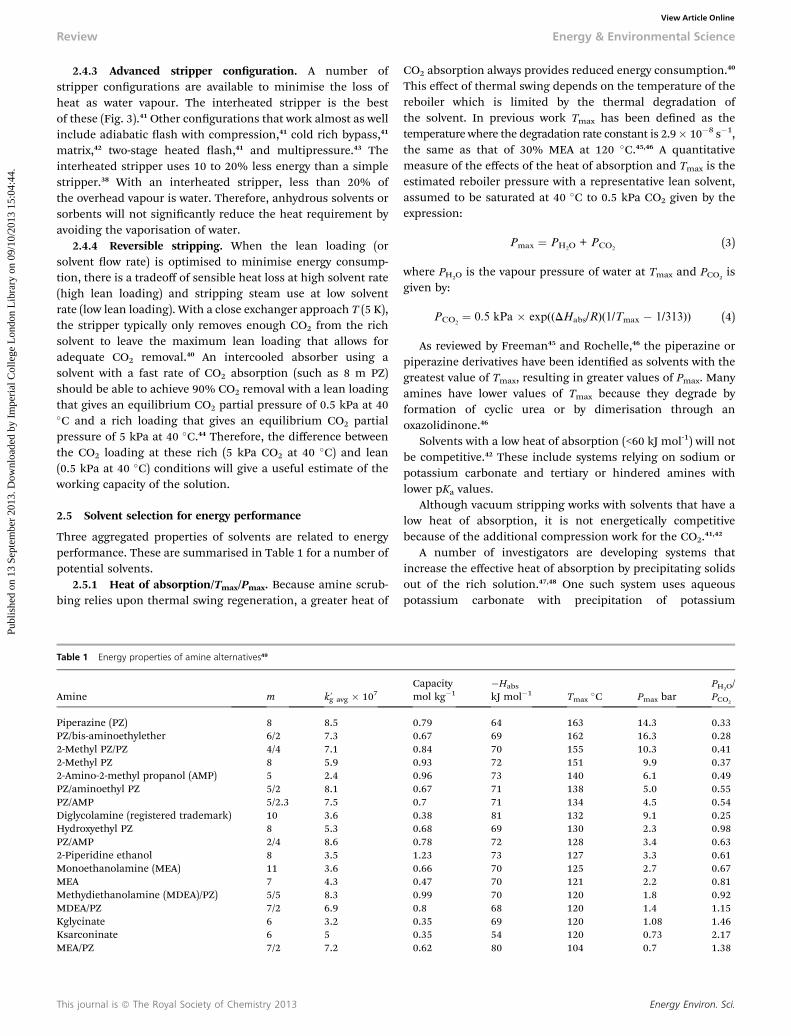
Three aggregated properties of solvents are related to energyperformance. These are summarised in Table 1 for a number ofpotential solvents.
2.5.1 Heat of absorption/Tmax/Pmax. Because amine scrub-bing relies upon thermal swing regeneration, a greater heat of
Table 1 Energy properties of amine alternatives49
Amine m k 0g avg � 107
Piperazine (PZ) 8 8.5PZ/bis-aminoethylether 6/2 7.32-Methyl PZ/PZ 4/4 7.12-Methyl PZ 8 5.92-Amino-2-methyl propanol (AMP) 5 2.4PZ/aminoethyl PZ 5/2 8.1PZ/AMP 5/2.3 7.5Diglycolamine (registered trademark) 10 3.6Hydroxyethyl PZ 8 5.3PZ/AMP 2/4 8.62-Piperidine ethanol 8 3.5Monoethanolamine (MEA) 11 3.6MEA 7 4.3Methydiethanolamine (MDEA)/PZ) 5/5 8.3MDEA/PZ 7/2 6.9Kglycinate 6 3.2Ksarconinate 6 5MEA/PZ 7/2 7.2
This journal is ª The Royal Society of Chemistry 2013
CO2 absorption always provides reduced energy consumption.40
This effect of thermal swing depends on the temperature of thereboiler which is limited by the thermal degradation ofthe solvent. In previous work Tmax has been dened as thetemperature where the degradation rate constant is 2.9� 10�8 s�1,the same as that of 30% MEA at 120 �C.45,46 A quantitativemeasure of the effects of the heat of absorption and Tmax is theestimated reboiler pressure with a representative lean solvent,assumed to be saturated at 40 �C to 0.5 kPa CO2 given by theexpression:
Pmax ¼ PH2O+ PCO2
(3)
where PH2O is the vapour pressure of water at Tmax and PCO2is
given by:
PCO2¼ 0.5 kPa � exp((DHabs/R)(1/Tmax � 1/313)) (4)
As reviewed by Freeman45 and Rochelle,46 the piperazine orpiperazine derivatives have been identied as solvents with thegreatest value of Tmax, resulting in greater values of Pmax. Manyamines have lower values of Tmax because they degrade byformation of cyclic urea or by dimerisation through anoxazolidinone.46
Solvents with a low heat of absorption (<60 kJ mol-1) will notbe competitive.42 These include systems relying on sodium orpotassium carbonate and tertiary or hindered amines withlower pKa values.
Although vacuum stripping works with solvents that have alow heat of absorption, it is not energetically competitivebecause of the additional compression work for the CO2.41,42
A number of investigators are developing systems thatincrease the effective heat of absorption by precipitating solidsout of the rich solution.47,48 One such system uses aqueouspotassium carbonate with precipitation of potassium
Capacitymol kg�1
�Habs
kJ mol�1 Tmax�C Pmax bar
PH2O/PCO2
0.79 64 163 14.3 0.330.67 69 162 16.3 0.280.84 70 155 10.3 0.410.93 72 151 9.9 0.370.96 73 140 6.1 0.490.67 71 138 5.0 0.550.7 71 134 4.5 0.540.38 81 132 9.1 0.250.68 69 130 2.3 0.980.78 72 128 3.4 0.631.23 73 127 3.3 0.610.66 70 125 2.7 0.670.47 70 121 2.2 0.810.99 70 120 1.8 0.920.8 68 120 1.4 1.150.35 69 120 1.08 1.460.35 54 120 0.73 2.170.62 80 104 0.7 1.38
Energy Environ. Sci.
Energy & Environmental Science Review
Publ
ishe
d on
13
Sept
embe
r 20
13. D
ownl
oade
d by
Im
peri
al C
olle
ge L
ondo
n L
ibra
ry o
n 09
/10/
2013
15:
04:4
4.
View Article Online
bicarbonate. These processes will ultimately have to deal withthe reliability issues posed by precipitating slurries.
2.6 Normalised capacity – capacity/(m/10)0.25
The capacity and viscosity of the solvent are reected in thesensible heat requirement of the stripper, given by:
Qsensible
�kJ
mol CO2
�¼ CpDT
C(5)
where Cp is the heat capacity of the solvent (kJ kg(H2O +amine)�1 K�1), DT is the hot side approach T of the crossexchanger, and C is the capacity of the solvent (mol CO2 kg(H2O+ amine)�1).
One quantitative measure of the intrinsic solvent capacity isthe difference between the equilibrium CO2 concentration at40 �C at 5 kPa CO2 and the equilibrium concentration at 40 �C at0.5 kPa. These values allow for a reasonable driving force toprovide 90% CO2 removal at conditions of coal-red powerplants. These convenient units of capacity reect the general-isation that the effective partial molar heat capacity of CO2
loading is typically near zero.Greater solvent viscosity reduces the heat transfer coefficient
in the cross-exchanger. The optimum exchanger design willresult in a greater approach DT with a greater viscosity. There-fore, it is appropriate to weight the intrinsic capacity by theviscosity to the �0.25 power, as reected in the normalisedcapacity given in Table 1, capacity/(m/10)0.25.49
A number of amine systems provide greater normalisedcapacity than 7 M MEA. Hindered and tertiary amines usuallyprovide greater capacity because their intrinsic stoichiometryrequires only 1 mol amine mol CO2
�1, as opposed to two forthe MEA system. As shown in Table 1, methyldiethanolamine,(a tertiary amine) with piperazine and aminomethylpiperazine(a hindered amine) with piperazine are quite competitive.Greater capacity is also provided by diamines such as piperazinebecause more equivalents of amine can be loaded into thesolvent before the viscosity becomes unacceptable.
A number of researchers are investigating systems thatprecipitate solids or separate a lean amine organic phase fromthe rich solvent.50–52 These phase change systems will usuallyprovide greater capacity, but they must deal with the reliabilityissues posed by precipitating slurries or two-phase systems.
2.7 Rate of CO2 absorption, k0g
Because the optimisation of the absorber design will require lowerrich and lean loading to achieve 90% CO2 removal with areasonable amount of packing, the rate of CO2 absorption is animportant energy parameter of the solvent. A fast rate of CO2
absorption facilitates reversible absorber performance at high richand lean loading that will minimise energy use in an optimisedsystem. CO2 typically absorbs by the process of diffusion with fastreaction in the boundary layer. The normalised absorption ux ofCO2 (k
0g, mol m�2 Pa�1) is given approximately by:
k0g ¼
Flux
PCO2 ;i � P*CO2 ;b
¼ffiffiffiffiffiffiffiffiffiffiffiffiffiffiffiffiffiffiffiffiffiffiffiffiffiffiffiffiffiffiffiffiffiffikamðamineÞDCO2
pHCO2
(6)
Energy Environ. Sci.
k 0g is a property of the amine, and not of the absorber contactingdevice. It can be measured in a wetted wall column or similardevice. The value of k 0
g at an average loading is given for anumber of solvents in Table 1.
Piperazine or piperazine derivatives provide the greatestvalues of k 0
g. Secondary or primary amines are usually necessaryto provide an acceptable rate of CO2 absorption. Tertiary aminesand hindered amines are usually too slow to be used bythemselves.
Several investigators are developing carbonic anhydraseenzymes to catalyse the CO2 kinetics in otherwise slowersolvents.53,54 Unfortunately they have not yet developedenzymes that are effective at elevated T (>100 �C). Further-more, the enzymes are most effective in tertiary amines andcarbonate solutions with low heats of CO2 absorption. Thesesystems will probably not be energetically competitive withother second generation amine solvents that can be regen-erated at 120 to 150 �C.
2.8 Solvent management
2.8.1 Oxidative degradation. Monoethanolamine oxidisesat absorber conditions with catalysis by dissolved iron andmanganese.55 This oxidation rate seems to have been econom-ically and environmentally acceptable in previous systems.35
However, it is a nuisance and may be environmentally unac-ceptable in larger systems. Inhibitors have been identied thatare effective at absorber conditions.55 These additives appear todegrade or are ineffective when used in cyclic systems withelevated T representative of strippers.56
A number of amines are resistant to oxidation at absorberconditions, including piperazine, tertiary amines, and hinderedamines. Tertiary amines appear to be oxidation inhibitors whenused in blends with other amines. MDEA is effective in inhib-iting the oxidation of MEA at absorber conditions.56,57
However, Closmann56 and Voice57 have shown in bench-scaleexperiments that even resistant amines are subject to reactionwith dissolved and entrained oxygen that is carried into the hightemperature of the cross-exchanger. This oxidation rate dependson the solubility of oxygen in the solvent and can be substantiallyless than that in MEA solvents. It can be minimised by strippingthe dissolved oxygen from the rich solution with nitrogen or by alow-temperature ash of CO2/H2O.
2.8.2 Other ue gas impurities. Coal-red ue gas containsa number of impurities that impact processes for post-combustion capture. Existing plants that treat coal-red ue gasinclude gas pretreating with sodium alkali scrubbing to removepractically all of the SO2, HCl, and coarser yash. This pre-treating would not be expected to remove NOx, Hg, submicrony ash, and submicron H2SO4 aerosol.
2.8.3 Nitrosamines. Secondary amines will combine withNO2 in the inlet ue gas to produce nitrosamines that maycreate environmental risk in spills of disposal of spentsolvent. It is probable that NO2 in the absorber inlet will bemostly absorbed by reaction with secondary and tertiaryamines to produce nitrite.58 At 100 to 150 �C in the stripper,nitrite reacts with secondary amines to quantitatively produce
This journal is ª The Royal Society of Chemistry 2013
Review Energy & Environmental Science
Publ
ishe
d on
13
Sept
embe
r 20
13. D
ownl
oade
d by
Im
peri
al C
olle
ge L
ondo
n L
ibra
ry o
n 09
/10/
2013
15:
04:4
4.
View Article Online
nitrosamines.58 At 150 �C, nitrosopiperazine thermally decom-poses, so it will reach a steady-state concentration where the rateof decomposition is equal to the rate at which NO2 enters theabsorber. Pilot plant data with piperazine-based solvent suggesta steady-state concentration of about 1 mM nitrosopiperazine attypical power plant conditions using a stripper at 150 �C.59 Thissteady-state concentration will increase at lower stripper T andwith ue gas containing more NO2, so other solvents andconditions may experience greater steady-state concentration.Amine solvents that do not include secondary amines may stillbe subject to this reaction with oxidative and thermal degrada-tion product of the primary or tertiary amines that make up thesolvent.60 Nitrosodiethanolamine has been found in mono-ethanolamine solvent.61 UV treating is being tested as a methodto selectively decompose nitrosamine in amine solvents.62–64 Thevolatility of the nitrosamine is expected to be comparable to thatof the parent amine.58 Any gaseous emissions of nitrosamineshould also be quickly decomposed by UV exposure in theatmosphere. Therefore, air emission of nitrosamine should posenegligible risk.65
2.8.4 Amine volatilityVapour losses. Because practical amines usually include at least
two or more hydrophilic groups such as amine, alcohol, or ether,residual amine volatility at the top of the stripper can bemanaged to less than 1 ppm by a water wash. Nguyen66measuredamine volatility in water and showed that two or more hydro-philic groups usually produce an amine volatility less than100 ppm at absorber lean conditions. In solutions loaded withCO2, diamines such as piperazine are substantially less volatilebecause of speciation to ions including protonated amine andcarbamate.67 Hindered amines and tertiary amines with methylgroups tend to have greater volatility. Aliphatic monoamineswithout other polar groups have unacceptable volatility.
Several investigators68 have been developing systems withamino acids (partially neutralised by K+) which should benonvolatile ions. Other vendors may be using amines such ashydroethylpiperazine with three or more hydrophilic groups thathave practically no volatility and may not require a water wash.
Amine aerosols. Vapour amine may condense in the absorberon submicron hydrophilic aerosol or particulate to producesmall aerosol drops that are not removed by typical contactinginternals in the absorber or water wash.69 Several pilot plantshave reported amine emissions as high as 200 ppm from pilotplants with 1 to 3 ppm SO3 in the inlet ue gas.70–73 The resultingaerosol can be effectively removed by a bre lter mist elimi-nator with a pressure drop of 150 to 250 mmH2O.74 Aker CleanCarbon and MHI claim solutions to this problem.74 Thisproblem could also be addressed by using an amine or aminoacid with low or no volatility.
2.9 Development status
Since 1930, hundreds of plants have used amine scrubbing toremove CO2 from hydrogen, natural gas, and other gases thatcontain little oxygen. The plants use monoethanolamine,diethanolamine, MDEA/PZ, and a number of second and thirdgeneration solvents.
This journal is ª The Royal Society of Chemistry 2013
Amine scrubbing for CO2 capture from natural gas iscommercially available. Since 1980, dozens of plants havecaptured CO2 from combustion of methane or other clean fuels.Most are based on technology provided by Fluor (MEA, Econo-mine) or MHI (KS-1). The Fluor applications include a 70 MWe
gas-red boiler and a gas-red turbine with a ue gas rateequivalent to 80 MW of a coal-red boiler.
Two public databases demonstrate that amine scrubbing isnear commercial on coal-red power plants.75,76 More than25 pilot plants have tested amine absorption/stripping on coal-red ue gas at 0.1 to 5 MWe. Seven prototype systems havebeen operated at 10 to 33 MW with coal-red ue gas andcompression of the CO2. There are no larger plants operating oncoal-red gas, but one is under construction at 120 MW andanother eight plants at 140 to 765 MW in various states ofplanning, permitting, and FEED.
2.10 Conclusions
Advanced amine systems will capture CO2 with heat duty lessthan 2.7 MJ tCO2
�1 and equivalent work less than 250 kWhtCO2
�1 (including compression to 150 bar).The innovations contributing to reduced energy use include:(1) Thermally stable amines such as 8 m piperazine that can
be regenerated at elevated pressure.(2) Effective plate-and-frame cross exchangers and high
capacity solvents such as PZ/MDEA and PZ/AMP.(3) Congurations such as the interheated stripper that
effectively recover heat from the stripper overhead.(4) Fast amines such as piperazine and absorber intercooling
that provide more reversible absorber operation with greaterrich and lean loading.
(5) Amines with high heat of CO2 absorption that maximisethe energy performance of thermal swing regeneration.
Remaining issues of secondary environmental impact withadvanced amines have acceptable solutions:
(1) Amine oxidation can be minimised by using amines suchas piperazine and MDEA that are resistant to oxidation and bystripping dissolved oxygen at <100 �C.
(2) Nitrosamines can be managed by avoiding secondaryamines or by thermal or UV decomposition.
(3) Vapour losses of amine can be avoided by water wash withvolatile amines or by using non-volatile amines.
(4) Amine aerosol losses can be eliminated by a bre lter.
3. Ionic liquids as alternative solvents forCCS
It has been suggested that the use of ionic liquids (ILs) asalternative solvents would have many advantages over conven-tional amine-based CO2 extraction. The general area of IL usefor CCS has been reviewed recently.77–84 In addition to apotentially lower demand for energy in the solvent regenerationstep, ILs have lower volatility, lower vapour pressure, are non-ammable, are more thermally stable, and are easier to recycle.
Energy Environ. Sci.
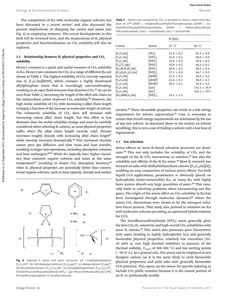
Table 2 Henry's Law constants for CO2 in selected ILs. Data is taken from Mul-doon et al.85 [eFAP] ¼ tris(pentafluoroethyl)trifluorophosphate; [pFAP] ¼ tris-(heptafluoropropyl)trifluorophosphate; [bFAP] ¼ tris(nonafluorobutyl)-trifluorophosphate; [ace] ¼ acesulfamate; [sac] ¼ saccharinate
Cation Anion
H (bar)
25 �C 60 �C
[C4C1im] [PF6] 53.4 � 0.3 81.3 � 0.8[C4C1im] [NTf2] 33.0 � 0.3 48.6 � 0.9[C6C1im] [NTf2] 31.6 � 0.2 45.6 � 0.3[C6(
3C1)py] [NTf2] 32.8 � 0.2 46.2 � 0.3[(C6H4F9)C1im] [NTf2] 28.4 � 0.1 48.5 � 0.4[(C8H4F13)C1im] [NTf2] 27.3 � 0.2 44.7 � 0.5[C6C1im] [eFAP] 25.2 � 0.1 42.0 � 0.1[C6C1im] [pFAP] 21.6 � 0.1 36.0 � 0.3[C5C1im] [bFAP] 20.2 � 0.1 32.9 � 0.2[C6C1im] [ace] 113.1 � 16.9[C6C1im] [sac] 132.2 � 19.7[Et3NBH2C1im] [NTf2] 33.1 � 1.2
Energy & Environmental Science Review
Publ
ishe
d on
13
Sept
embe
r 20
13. D
ownl
oade
d by
Im
peri
al C
olle
ge L
ondo
n L
ibra
ry o
n 09
/10/
2013
15:
04:4
4.
View Article Online
The comparison of ILs with molecular organic solvents hasbeen discussed in a recent review3 and also discussed thegeneral implications of changing the cation and anion (seeFig. 4) or employing mixtures. The recent developments in thiseld will be reviewed here, and the implications of IL physicalproperties and functionalisation on CO2 solubility will also beexplored.
3.1 Relationship between IL physical properties and CO2
solubility
Henry's constant is a quick and useful measure of CO2 solubilityin ILs. Henry's law constants for CO2 in a range of different ILs areshown in Table 2. The highest solubility of CO2 recently reportedwas in [C5C1im][bFAP], which contains a highly uorinatedalkylphosphate anion that is exceedingly non-coordinating,resulting in an open uid structure that dissolves CO2.85 As can beseen from Table 2, increasing the length of the alkyl side chain onthe imidazolium cation improves CO2 solubility.86 However, thehigh molar solubility of CO2 with increasing n-alkyl chain lengthis largely a function of the increase inmolecular weight of solvent.The volumetric solubility of CO2 does still decrease withincreasing cation alkyl chain length, but this effect is lessdramatic than the molar solubility change and must be carefullyconsidered when selecting IL cations, as most physical propertiessuffer when the alkyl chain length exceeds octyl. Densityincreases roughly linearly with increasing alkyl chain length87
while viscosity increases dramatically.88 This increased viscositycauses poor gas diffusion and slow mass and heat transfer,resulting in larger unit operations, including absorption columnsand heat exchangers.89,90 While ILs typically have higher viscosi-ties than common organic solvents and water at the sametemperature91 (resulting in slower CO2 absorption kinetics),80
other IL physical properties are potentially better than conven-tional organic solvents, such as heat capacity, density and surface
Fig. 4 Selected IL cation and anion structures. (a) 1,3-dialkylimidazolium[CnCmim]+; (b) N,N-dialkylpyrrolidinium [CnCmpyrr]
+; (c) alkylpyridinium [Cnpyr]+;
(d) tetraalkylammonium [CwCxCyCzN]+; (e) tetraalkylphosphonium [CwCxCyCzP]
+;(f) bis(trifluoromethylsulfonyl)imide [NTf2]
�; (g) trifluoromethanesulfonate [OTf];(h) hexafluorophosphate; (i) tetrafluoroborate.
Energy Environ. Sci.
tension.92 These favourable properties can result in a low energyrequirement for solvent regeneration.93 Care is necessary toensure that overall energy requirements areminimised by the useof any new solvent. As discussed above in the section on solventscrubbing, this is not a case of nding a solvent with a low heat ofregeneration.
3.2 Ion selection
Anion effects on most IL-based solvation processes are domi-nant.94 This not only includes the solubility of CO2 and thestrength of the IL–CO2 interactions in solution,95 but also thesolubility and affinity of the IL for water.94 Most IL research hasfocused on salts with dialkylimidazolium cations ([CnCmim][X]),enabling an easy comparison of various anion effects. For bulkliquid CCS applications, prominence is obviously placed onhydrophobic (water-immiscible) ILs, as many ILs with highlybasic anions absorb very large quantities of water.94 This natu-rally leads to selectivity problems when encountering wet uegases. The origin of the anion effect on CO2 solubility in ILs hasbeen investigated through molecular dynamics86 where theanion–CO2 interactions were shown to be the strongest solva-tion forces present. That study also pointed to mixtures on ILswith molecular solvents providing an optimised hybrid solutionfor CCS.
The bistriuorosulfonylimide [NTf2] anion generally givesthe best CO2:N2 selectivity and high overall CO2 solubilities withmost IL cations.96 This anion also possesses poor interactionswith water (leading to highly hydrophobic ILs) and generallyfavourable physical properties: relatively low viscosities (20–50 mPa s), very high thermal stabilities (a measure of thethermal stability, Tonset of 400–500 �C) and low melting points(�50–0 �C). As a general rule, this anion can be employed to testdesigner cations (as it is the most likely to yield favourablephysical properties) and yield salts with generally favourableCCS potential. This opens up the cation for specic tailoring toinclude CO2-philic moieties because it is the easiest portion ofan IL to synthetically modify.
This journal is ª The Royal Society of Chemistry 2013
Review Energy & Environmental Science
Publ
ishe
d on
13
Sept
embe
r 20
13. D
ownl
oade
d by
Im
peri
al C
olle
ge L
ondo
n L
ibra
ry o
n 09
/10/
2013
15:
04:4
4.
View Article Online
3.3 Conventional ILs
Unfortunately, there is currently no comprehensive model forgas solubility in ILs.97 However, some general trends can beobserved. Increasing the cation alkyl side chain length increasesCO2 solubility, likely by increasing the available volume for CO2
due to a decrease in cation–anion interactions.98,99 It is clear thatthere are mainly physical phenomena (such as dispersionforces) dominating CO2–IL interactions when unfunctionalisedILs are employed, with only weak chemical complexes form-ing.100 The enthalpy of CO2 physical absorption by these ILs isgenerally about 20 kJ mol�1. This results in a lower energyrequirement than for amine solutions in the regeneration step,but not overall: as discussed above, a lower heat of absorptioncan lead to a higher overall energy requirement. The structuralexibility of ILs allow tuning of the enthalpy of absorption byemploying basic ionic liquids made by neutralising tetraalkyl-phosphonium hydroxide with weak proton donors withdifferent pKa values.101 These basic ILs have more rapidabsorption rates with little increase in viscosity, though this islikely to be very sensitive to water as these are hydrophilicanions.
Fig. 5 Reaction of CO2 at the C2 position with in situ-generated carbine.113
3.4 Task-specic ILs
Conventional ILs mostly use physical absorption to capture CO2
through the space between ions, while functionalised (task-specic) ILs are usually designed to chemically bond to CO2 inan absorption process, increasing the overall absorptioncapacity.80 The synthetic exibility of ILs means that a near-innite range of functionalisations are possible, though costand stability become important considerations. However, onlysome functionalisation strategies have increased CO2 capacity.This eld of task-specic ILs (TSILs) for CCS applications hasrecently undergone rapid growth.82
3.4.1 Fluorinated ILs. Incorporation of peruoroalkylgroups in ILs increases CO2 solubility compared to non-uori-nated inorganic anions such as nitrate and dicyanamide.102 Thiscan be attributed to the large affinity of CO2 for the per-uoroalkyl chains. The increase in CO2 solubility is minimalwhen the peruoroalkyl chains are employed on the cation ofthe IL, but very large when added to the anion. However, thesemodications are generally avoided due to environmentalconcerns surrounding peruorocarbons. Oxygen-containingfunctional groups can serve as alternative sources of interactionwith the electron-poor carbon atom of CO2 with similar effect.77
3.4.2 Amine-functionalised and amino-acid ionic liquids(AAILs). Amino-functionalised ILs provide strong complexationpotential with CO2 by duplicating much of the amine characterof molecular CCS solvents. Amine character can be inserted intoeither the cation or the anion of the IL. Amine-functionalisedside chains103,104 provide chemisorption at the stoichiometricratio of IL : CO2 of 2 : 1 as with amine-based solvents, thoughthe nature of the carbamate complex is still under dispute.103
Unfortunately, these ILs generally have poorer thermal stabili-ties and higher melting points and viscosities than conven-tional ILs.105 A variety of cations (imidazolium, pyridinium,ammonium and phosphonium) have been be functionalised
This journal is ª The Royal Society of Chemistry 2013
with amines for CO2 capture, with (3-aminopropyl)tribu-tylphosphonium ILs (coupled with amino acid anions) exhibitingthe best physicochemical properties, such as a low glass transi-tion temperatures (in the range from �69.7 to �29.6 �C) andthermal stability to above 200 �C.105 The salt (2-hydroxyethyl)-trimethyl-ammonium(S)-2-pyrrolidine-carboxylic acid salt or[Choline][Pro] has been demonstrated to be able to capture andrelease CO2, where CO2 is released by bubbling N2 in the solu-tion106 (of course, further measurements are necessary under aCO2 atmosphere). There is, however, some concern over meltingpoint changes when amino acid anions absorb CO2.82
A variety of imidazolium or tetraalkylphosphonium cationshave been combined with amino acid anions to makeAAILs.107–109 Potential advantages of using amino acids includetheir low cost, biodegradability and low toxicity. Also, AAILs canincrease CO2 capture because they possess both carboxyl andamine functional groups and the IL can complex CO2 in a 1 : 1stoichiometric ratio.110 Immobilisation of AAILs into nano-porous PMMA microspheres has recently been shown toincrease CO2 uptake rates and ease regeneration.111
As mentioned above, amine-functionalised ILs tend to behighly viscous, which leads to problems of measuring CO2
capacity and developing handling strategies, and also results inthe hindrance of CO2 diffusion rates.102 These ILs also requireextra synthetic and purication steps to produce, which willlikely increase the expenses.77 One way to overcome the viscosityproblem is to use a solid support. However, this requires solid/gas exchange, which is quite challenging in practice. Theconventional MEA process solves the viscosity problem bydiluting theMEA with water. However, this is not ideal as a largeamount of water needs to be evaporated to regenerate the IL.102
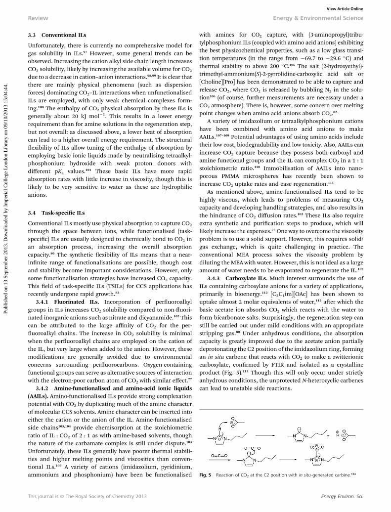
3.4.3 Carboxylate ILs. Much interest surrounds the use ofILs containing carboxylate anions for a variety of applications,primarily in bioenergy.112 [C2C1im][OAc] has been shown touptake almost 2 molar equivalents of water,112 aer which thebasic acetate ion absorbs CO2 which reacts with the water toform bicarbonate salts. Surprisingly, the regeneration step canstill be carried out under mild conditions with an appropriatestripping gas.80 Under anhydrous conditions, the absorptioncapacity is greatly improved due to the acetate anion partiallydeprotonating the C2 position of the imidazolium ring, formingan in situ carbene that reacts with CO2 to make a zwitterioniccarboxylate, conrmed by FTIR and isolated as a crystallineproduct (Fig. 5).113 Though this will only occur under strictlyanhydrous conditions, the unprotected N-heterocyclic carbenescan lead to unstable side reactions.
Energy Environ. Sci.
Scheme 2 Proposed mechanisms of CO2 capture by AAILs: (a) and (b) withoutwater; (c) with water.129
Energy & Environmental Science Review
Publ
ishe
d on
13
Sept
embe
r 20
13. D
ownl
oade
d by
Im
peri
al C
olle
ge L
ondo
n L
ibra
ry o
n 09
/10/
2013
15:
04:4
4.
View Article Online
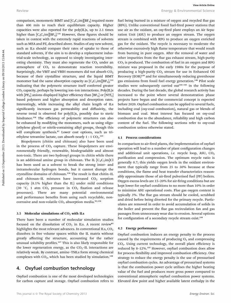
3.4.4 Reversible ILs. Reversible ILs, based on amidinium(i.e. DBU) or guanidinium alkylcarbonate salts, also show goodCO2 reactivity and high absorption capacity.114–119 The “molec-ular” state of the system consists of a 1 : 1 mixture of a protondonor (i.e. alcohol) and organic base, and shows excellent CO2
capacity and good CO2 : N2 selectivities (Scheme 1).101,120–122
These new ILs are interesting CO2 capture options, though thehigher volatility of the alcohol component may hinder deploy-ment. To avoid this, the alcohol group can be incorporated intoan IL cation side chain.123 CO2 absorbances of 1.04 : 1 (relativeto base) have been reported for this strategy, which is 20 timeshigher than the solubility in the neat IL, and can be achieved inunder 10 min.123 CO2 release can be achieved by mild heating(90–120 �C) and the IL re-used. It should be noted that for verystrong bases (e.g. MTBD, tetramethylguanidine), CO2 mayactually react with the IL cation,124 which would imply sensi-tivity of CO2 absorbance to H2O presence. Functionalisation ofthe guanidines or amidines, including tethering of the alcoholgroup to the base,125 may avert these difficulties.
3.4.5 Protic ILs. One way to overcome the high cost ofdialkylimidazolium cation synthesis is to use protic ILs, whichare acid–base complexes.120 If a weak acid is employed, then astrong CO2 complex can be formed, though these ILs will be veryhydrophilic. Functionalised protic ILs can dissolve large quan-tities of CO2 under anhydrous conditions; those based onuorinated alcohols have been shown to capture 2.04 molarequivalents of CO2, and the viscosities of these salts is relativelylow (8.63mPa s). Unfortunately, these specic ILs are unlikely tobe stable in the presence of water.
3.4.6 Supported ionic liquid membranes (SILMs). The useof ILs in membrane separation is a growing eld.126 SILMs canbe used to separate organic compounds, mixed gases, and ions.SILMs have many potential advantages in CO2 capture,including very high thermal and chemical stabilities, extremelylow volatilities and increased contact area between the gas andILs, overcoming many of the viscosity limitations on uptakerate.81 CO2 can be successfully separated from N2 and CH4 bypolymer lms of ILs which are polymerised by styrene andacrylate monomers. The SILMs based on task-specic TSILs,such as [(3NH2)C3C1im][NTf2] and [(3NH2)C3C1im][OTf] havealso been explored.127 These TSILs contain functional groupscapable of chemically complexing with CO2. They show higherselectivity in CO2 separation than [C4C1im][NTf2] for CO2–CH4
gas mixtures because the amine group facilitates CO2 transport
Scheme 1 CO2 capture mechanism for reversible ILs.122
Energy Environ. Sci.
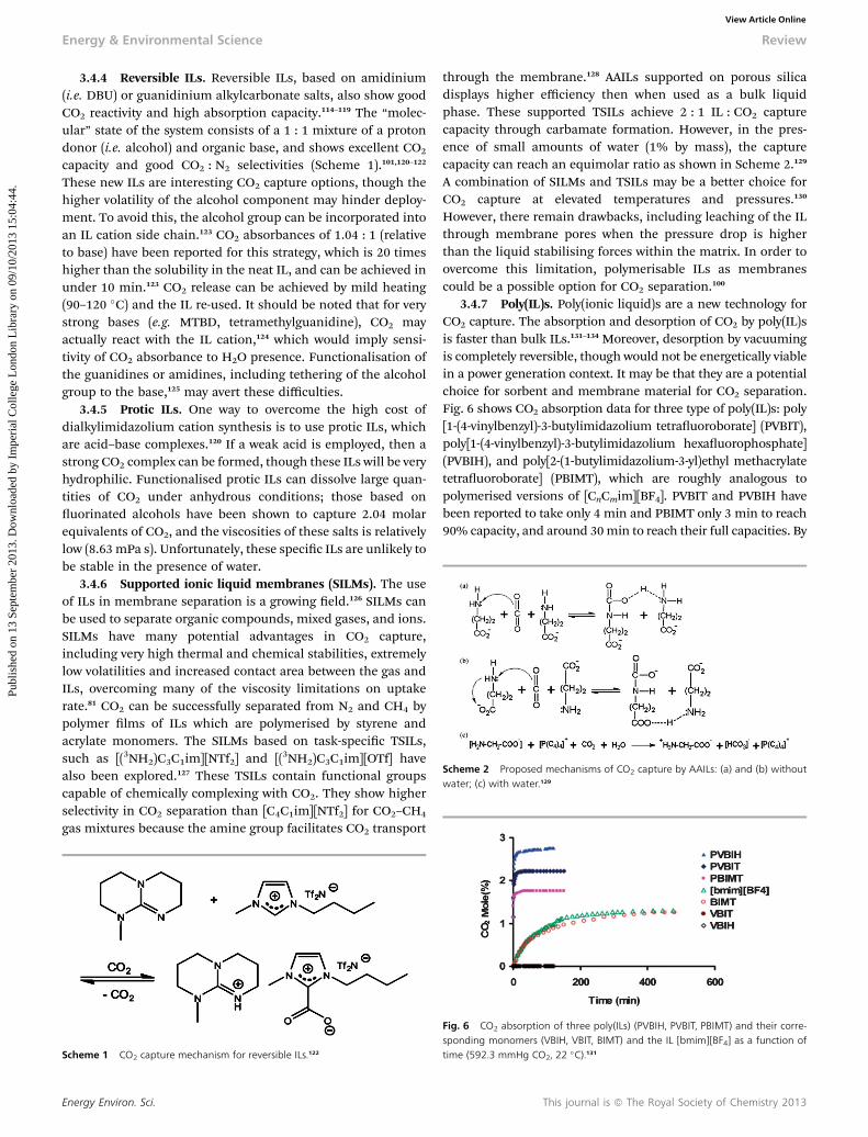
through the membrane.128 AAILs supported on porous silicadisplays higher efficiency then when used as a bulk liquidphase. These supported TSILs achieve 2 : 1 IL : CO2 capturecapacity through carbamate formation. However, in the pres-ence of small amounts of water (1% by mass), the capturecapacity can reach an equimolar ratio as shown in Scheme 2.129
A combination of SILMs and TSILs may be a better choice forCO2 capture at elevated temperatures and pressures.130
However, there remain drawbacks, including leaching of the ILthrough membrane pores when the pressure drop is higherthan the liquid stabilising forces within the matrix. In order toovercome this limitation, polymerisable ILs as membranescould be a possible option for CO2 separation.100
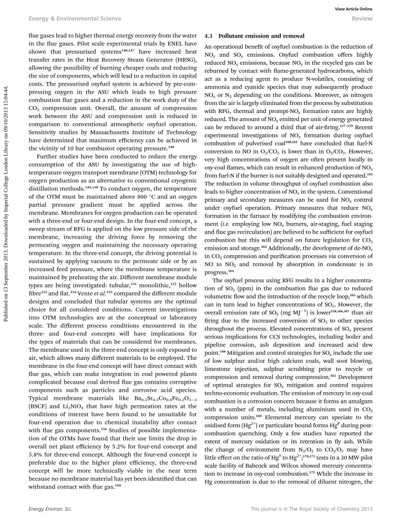
3.4.7 Poly(IL)s. Poly(ionic liquid)s are a new technology forCO2 capture. The absorption and desorption of CO2 by poly(IL)sis faster than bulk ILs.131–134 Moreover, desorption by vacuumingis completely reversible, though would not be energetically viablein a power generation context. It may be that they are a potentialchoice for sorbent and membrane material for CO2 separation.Fig. 6 shows CO2 absorption data for three type of poly(IL)s: poly[1-(4-vinylbenzyl)-3-butylimidazolium tetrauoroborate] (PVBIT),poly[1-(4-vinylbenzyl)-3-butylimidazolium hexauorophosphate](PVBIH), and poly[2-(1-butylimidazolium-3-yl)ethyl methacrylatetetrauoroborate] (PBIMT), which are roughly analogous topolymerised versions of [CnCmim][BF4]. PVBIT and PVBIH havebeen reported to take only 4 min and PBIMT only 3 min to reach90% capacity, and around 30min to reach their full capacities. By
Fig. 6 CO2 absorption of three poly(ILs) (PVBIH, PVBIT, PBIMT) and their corre-sponding monomers (VBIH, VBIT, BIMT) and the IL [bmim][BF4] as a function oftime (592.3 mmHg CO2, 22 �C).131
This journal is ª The Royal Society of Chemistry 2013
Review Energy & Environmental Science
Publ
ishe
d on
13
Sept
embe
r 20
13. D
ownl
oade
d by
Im
peri
al C
olle
ge L
ondo
n L
ibra
ry o
n 09
/10/
2013
15:
04:4
4.
View Article Online
comparison, monomeric BIMT and [C4C1im][BF4] required morethan 400 min to reach their equilibrium capacity. Highercapacities were also reported for the poly(IL)s, up to 2.1 timeshigher than [C4C1im][BF4].131 However, these gures should betaken in context with the extremely rapid reactions of solventssuch asMEA and PZ, described above. Studies of any new solvent,such as ILs should compare their rates of uptake to those ofstandard solvents, if the aim is to develop a replacement indus-trial-scale technology, as opposed to simply investigating inter-esting chemistry. They must also regenerate the CO2 under anatmosphere of CO2 to demonstrate reaction reversibility.Surprisingly, the VBIT and VBIH monomers did not absorb CO2
because of their crystalline structure, and the liquid BIMTmonomer had the same absorption capacity as [C4C1im][BF4],131
indicating that the polymeric structure itself conferred greaterCO2 capacity, perhaps by lowering ion–ion interactions. Poly(IL)swith [PF6] anions displayed higher efficiency than [BF4] or [NTf2]based polymers and higher absorption and desorption rates.Interestingly, while increasing the alkyl chain length of ILssignicantly increases gas permeability and diffusivity, thereverse trend is observed for poly(IL)s, possibly due to sterichindrance.134 The efficiency of polymeric structures can alsobe enhanced by modifying the monomers, such as using oligo-(ethylene glycol) or nitrile-containing alkyl groups, though thiswill complicate synthesis.87 Lower cost options, such as tri-ethylene tetramine lactate, can absorb nearly 1 : 1 CO2.135
Biopolymers (chitin and chitosan) also have been usedin the process of CO2 capture. These biopolymers are envi-ronmentally friendly, renewable, biodegradable and almostnon-toxic. There are two hydroxyl groups in chitin while thereis an additional amine group in chitosan. The IL [C4C1im]Clhas been used as a solvent to break the strong inter- andintramolecular hydrogen bonds, but it cannot disrupt thecrystalline domains of chitosan.136 The result is that chitin–ILand chitosan–IL mixtures have increased CO2 sorptioncapacity (8.1% higher than the IL) under mild conditions(30 �C, 1 atm CO2 pressure in CO2 xation and releaseprocesses). There are many potential environmentaland performance benets from using such recyclable, non-corrosive and non-volatile CO2 absorption media.93,136
3.5 Molecular simulations of CO2 with ILs
There have been a number of molecular simulation studiesfocused on the dissolution of CO2 in ILs. A recent review83
highlights the most relevant advances. In conventional ILs, CO2
dissolves in free volume spaces within the IL matrix withoutgreatly affecting the structure, accounting for the ratherunusual solubility proles.137 This is also likely responsible forthe lower regeneration energy, as the CO2–IL interactions arerelatively weak. By contrast, amine–TSILs form strong chemicalcomplexes with CO2, which has been studied by simulation.138
4. Oxyfuel combustion technology
Oxyfuel combustion is one of the most developed technologiesfor carbon capture and storage. Oxyfuel combustion refers to
This journal is ª The Royal Society of Chemistry 2013
fuel being burned in a mixture of oxygen and recycled ue gas(RFG). Unlike conventional fossil fuel-red power stations thatuse air as the oxidant, an oxy-red plant employs an Air Sepa-ration Unit (ASU) to produce an oxygen stream. The oxygenstream is combined with RFG to produce an oxygen enrichedgas for the oxidant. The recycle is necessary to moderate theotherwise excessively high ame temperature that would resultfrom burning in pure oxygen. Aer the removal of water andother impurities from the ue gas exhaust stream, high-purityCO2 is produced. The combustion of fuel in an oxygen and RFGmixture was proposed in the early 1980s for the purpose ofproducing a high-purity CO2 stream for use in Enhanced OilRecovery (EOR)139 and for simultaneously reducing greenhousegas emissions from fossil fuel energy generation.140 Pilot scalestudies were subsequently carried out141–143 in the followingdecades. During the last decade, the global research activity hasincreased to the point where several demonstration phaseprojects have begun and the commercial concept is expectedbefore 2020. Oxyfuel combustion can be applied to several fuels,including coal (oxy-coal combustion), natural gas or blends ofbiomass and coal. Most interest has focused on oxy-coalcombustion due to the abundance, reliability and high carboncontent of the fuel. The following sections refer to oxy-coalcombustion unless otherwise stated.
4.1 Process considerations
In comparison to air-red plants, the implementation of oxyfueloperation will lead to a number of plant conguration changesand additional unit operations, i.e. recycle loop, ASU, CO2
purication and compression. The optimum recycle ratio isgenerally 0.7; this yields oxygen levels in the oxidant environ-ment that typically range from 25 to 30% because at theseconditions, the ame and heat transfer characteristics reason-ably approximate those of air-red pulverised fuel (PF) boilers.Oxygen excess levels are 15–20% for air-ring conditions but arekept lower for oxyfuel conditions to no more than 10% in orderto minimise ASU operational costs. Flue gas oxygen content istypically 3%. The ue gas stream should be cooled, scrubbedand dried before being diverted for the primary recycle. Partic-ulates are removed in order to avoid accumulation of solids inthe boiler and prevent the ue gas recirculation fan and gaspassages from unnecessary wear due to erosion. Several optionsfor conguration of a secondary recycle stream exist.144
4.2 Energy performance
Oxyfuel combustion induces an energy penalty to the processcaused by the requirements of producing O2 and compressingCO2. Using current technology, the overall plant efficiency isreduced by 8–12%.145 However, oxyfuel combustion does allowfor process exibility and improved combustion efficiency. Onestrategy to reduce the energy penalty is the use of pressurisedoxyfuel combustion cycles. An advantage of pressurised systemsis that the combustion power cycle utilises the higher heatingvalue of the fuel and produces more gross power compared toconventional atmospheric oxyfuel combustion power systems.Elevated dew point and higher available latent enthalpy in the
Energy Environ. Sci.
Energy & Environmental Science Review
Publ
ishe
d on
13
Sept
embe
r 20
13. D
ownl
oade
d by
Im
peri
al C
olle
ge L
ondo
n L
ibra
ry o
n 09
/10/
2013
15:
04:4
4.
View Article Online
ue gases lead to higher thermal energy recovery from the waterin the ue gases. Pilot scale experimental trials by ENEL haveshown that pressurised systems146,147 have increased heattransfer rates in the Heat Recovery Steam Generator (HRSG),allowing the possibility of burning cheaper coals and reducingthe size of components, which will lead to a reduction in capitalcosts. The pressurised oxyfuel system is achieved by pre-com-pressing oxygen in the ASU which leads to high pressurecombustion ue gases and a reduction in the work duty of theCO2 compression unit. Overall, the amount of compressionwork between the ASU and compression unit is reduced incomparison to conventional atmospheric oxyfuel operation.Sensitivity studies by Massachusetts Institute of Technologyhave determined that maximum efficiency can be achieved inthe vicinity of 10 bar combustor operating pressure.148
Further studies have been conducted to reduce the energyconsumption of the ASU by investigating the use of high-temperature oxygen transport membrane (OTM) technology foroxygen production as an alternative to conventional cryogenicdistillation methods.149,150 To conduct oxygen, the temperatureof the OTM must be maintained above 800 �C and an oxygenpartial pressure gradient must be applied across themembrane. Membranes for oxygen production can be operatedwith a three-end or four-end design. In the four-end concept, asweep stream of RFG is applied on the low pressure side of themembrane, increasing the driving force by removing thepermeating oxygen and maintaining the necessary operatingtemperature. In the three-end concept, the driving potential issustained by applying vacuum to the permeate side or by anincreased feed pressure, where the membrane temperature ismaintained by preheating the air. Different membrane moduletypes are being investigated: tubular,151 monolithic,152 hollowbre153 and at.154 Vente et al.155 compared the different moduledesigns and concluded that tubular systems are the optimalchoice for all considered conditions. Current investigationsinto OTM technologies are at the conceptual or laboratoryscale. The different process conditions encountered in thethree- and four-end concepts will have implications forthe types of materials that can be considered for membranes.The membrane used in the three-end concept is only exposed toair, which allows many different materials to be employed. Themembrane in the four-end concept will have direct contact withue gas, which can make integration in coal powered plantscomplicated because coal derived ue gas contains corruptivecomponents such as particles and corrosive acid species.Typical membrane materials like Ba0.5Sr0.5Co0.8Fe0.2O3�x
(BSCF) and Li2NiO4 that have high permeation rates at theconditions of interest have been found to be unsuitable forfour-end operation due to chemical instability aer contactwith ue gas components.156 Studies of possible implementa-tion of the OTMs have found that their use limits the drop inoverall net plant efficiency by 5.2% for four-end concept and5.8% for three-end concept. Although the four-end concept ispreferable due to the higher plant efficiency, the three-endconcept will be more technically viable in the near termbecause no membrane material has yet been identied that canwithstand contact with ue gas.149
Energy Environ. Sci.
4.3 Pollutant emission and removal
An operational benet of oxyfuel combustion is the reduction ofNOx and SOx emissions. Oxyfuel combustion offers highlyreduced NOx emissions, because NOx in the recycled gas can bereburned by contact with ame-generated hydrocarbons, whichact as a reducing agent to produce N-volatiles, consisting ofammonia and cyanide species that may subsequently produceNOx or N2 depending on the conditions. Moreover, as nitrogenfrom the air is largely eliminated from the process by substitutionwith RFG, thermal and prompt-NOx formation rates are highlyreduced. The amount of NOx emitted per unit of energy generatedcan be reduced to around a third that of air-ring.157–159 Recentexperimental investigations of NOx formation during oxyfuelcombustion of pulverised coal160,161 have concluded that fuel-Nconversion to NO in O2/CO2 is lower than in O2/CO2. However,very high concentrations of oxygen are oen present locally inoxy-coal ames, which can result in enhanced production of NOx
from fuel-N if the burner is not suitably designed and operated.162
The reduction in volume throughput of oxyfuel combustion alsoleads to higher concentration of NOx in the system. Conventionalprimary and secondary measures can be used for NOx controlunder oxyfuel operation. Primary measures that reduce NOx
formation in the furnace by modifying the combustion environ-ment (i.e. employing low NOx burners, air-staging, fuel stagingand ue gas recirculation) are believed to be sufficient for oxyfuelcombustion but this will depend on future legislation for CO2
emission and storage.163 Additionally, the development of de-NOx
in CO2 compression and purication processes via conversion ofNO to NO2 and removal by absorption in condensate is inprogress.164
The oxyfuel process using RFG results in a higher concentra-tion of SO2 (ppm) in the combustion ue gas due to reducedvolumetric ow and the introduction of the recycle loop,165 whichcan in turn lead to higher concentrations of SO3. However, theoverall emission rate of SO2 (mg MJ�1) is lower158,166,167 than airring due to the increased conversion of SO2 to other speciesthroughout the process. Elevated concentrations of SOx presentserious implications for CCS technologies, including boiler andpipeline corrosion, ash deposition and increased acid dewpoint.168 Mitigation and control strategies for SOx include the useof low sulphur and/or high calcium coals, wall soot blowing,limestone injection, sulphur scrubbing prior to recycle orcompression and removal during compression.165 Developmentof optimal strategies for SOx mitigation and control requirestechno-economic evaluation. The emission ofmercury in oxy-coalcombustion is a corrosion concern because it forms an amalgamwith a number of metals, including aluminium used in CO2
compression units.169 Elemental mercury can speciate to theoxidised form (Hg2+) or particulate bound forms HgP during post-combustion quenching. Only a few studies have reported theextent of mercury oxidation or its retention in y ash. Whilethe change of environment from N2/O2 to CO2/O2 may havelittle effect on the ratio of Hg0 to Hg2+;170,171 tests in a 30 MW pilotscale facility of Babcock and Wilcox showed mercury concentra-tion to increase in oxy-coal combustion.172 While the increase inHg concentration is due to the removal of diluent nitrogen, the
This journal is ª The Royal Society of Chemistry 2013
Review Energy & Environmental Science
Publ
ishe
d on
13
Sept
embe
r 20
13. D
ownl
oade
d by
Im
peri
al C
olle
ge L
ondo
n L
ibra
ry o
n 09
/10/
2013
15:
04:4
4.
View Article Online
increase in Hg oxidation may be explained by increased chlorineconcentration in oxyfuel combustion. Strategies to control Hgemissions include injection of activated carbon sorbents orforcing oxidation to water soluble Hg2+ forms to then be removedby conventional FGD scrubbing.
Air Products have developed the possibility of co-removal ofSOx, NOx and mercury during compression using their “SourGas Compression” technology.173 The process relies on theoxidation of NO to NO2 to convert SO2 to H2SO4
174 in the pres-ence of water. Mercury will dissolve and react in the nitric acidformed as a condensate. The technology is based on the “leadchamber process”. Further investigations are required todetermine the kinetics at higher pressure. Further pilot-scalework in this area has been performed by CANMET175 and at thelaboratory scale (e.g. Chalmers University, Sweden176 andImperial College London177).
Little information on the behaviour under oxyfuel conditionsof other pollutants such as particulates, other trace metals (Pb,As, Cd, Se, etc.), volatile organic compounds (VOCs), poly-aromatic hydrocarbons, dioxins and other chlorinatedcompounds are currently available. More investigations of therelease and distribution of these substances under oxyfuelconditions are required.
4.4 Computational uid dynamics modelling
Oxyfuel combustion presents numerous opportunities andchallenges for numerical modelling.178 Extensive use ofComputational Fluid Dynamics (CFD) modelling tools for thescale-up and advanced design of oxy-coal combustion facilitiesis expected.179 Utility boilers can be modelled in 3D and theimpact of changing various design parameters on uid ow,heat transfer and chemical reactions in combustion can beinvestigated. CFD modelling for oxyfuel combustion relies onsub-models that were initially developed for air-ring condi-tions. While signicant progress has beenmade in adapting theCFD sub-models for application to oxyfuel conditions, some ofthe models require further modications and validation inorder to be reliably applied in the CO2 rich environment.
Char oxidation and burnout is inuenced by the highconcentrations of CO2 and H2O in oxyfuel combustion. Physicaleffects (heat capacity and mass transfer) and Arrheniusparameters for homogeneous and heterogeneous reactionsmust be adapted for accurate prediction of char burnout andthe transition between combustion regimes.
Reduced gas-phase chemical kinetic mechanisms which canbe adopted within CFD codes at acceptable levels of computa-tional cost require development for CO2 rich environments.
The dominant mode of heat transfer in both air and oxyfuelcombustion is radiation. Radiative heat transfer in oxyfuelcombustion is very different than air combustion due to alteredgas emission and absorption. To calculate radiation within autility boiler, the radiative transfer equation must be solved andcoupled with a radiative properties model that species thegaseous and particle properties. Efforts have recently beenmade to improve the models for gaseous radiative properties bymaking them applicable to oxyfuel combustion modelling.180
This journal is ª The Royal Society of Chemistry 2013
Accurate turbulence models are required since turbulencehas important effects on mixing, kinetics and heat transfer withgreater signicance under oxyfuel conditions. At present, Rey-nolds Averaged Navier Stokes (RANS) models are considered anacceptable compromise between accuracy and computationalcost. Large Eddy Simulations (LES) are more computationallyintensive and have recently been applied to oxyfuel combus-tion.178 LES was found to be capable of capturing the intermit-tency effects of the coal ame and the importance of gasradiative properties was also demonstrated in the calculations.As computational resources increase, more sophisticatedmethods such as LES should replace classical turbulencemodels for CFD.
4.5 Recent trials and developments
Pilot-scale and industrial demonstration projects for oxyfuelcombustion are crucial for verifying observations and theoriesfrom laboratory and bench-scale, in addition to proving thecommercial viability of the technology. Until now, all operatedpilot-scale and demonstration projects have been#100MWth insize, and are spread out between several countries. The majorityof projects have focused on the CO2 capture process only,without linking to CO2 transport and storage.181 Nevertheless,Vattenfall's Schwartze Pumpe 30 MWth plant in Eastern Ger-many, which began in 2008, became the world's rst full chainoxyfuel pilot demonstration,182 designed for 10 tpd of CO2,transported by refrigerated truck183 to several storage andindustrial sites. The 30 MWth Lacq project by Total in Franceuses natural gas as fuel and commenced in 2009. This was therst time an oxyfuel project has been coupled to pipelinetransport for geosequestration. The Lacq project does notinclude any inerts-removal step,184 so CO2 is transported at 92%purity and 27 bar along an existing pipeline through a popu-lated area. The CO2 is injected down to a depth of 4500 m into adepleted gas eld. The largest currently operating integratedCCS chain involving oxyfuel combustion is the Callide 30 MWe
oxyfuel project which began in 2011 in Australia.185 The CallideOxyfuel project is the rst demonstration of retrot to anexisting coal-red boiler with electricity generation supplied tothe open market and includes on-line coal milling.
Future commercial demonstration-scale oxyfuel plants haverecently been announced. Vattenfall's 250 MWth Jaenschwaldeplant in Germany will also generate electricity for the openmarket and has an operational aim of 2015. The FutureGen2 Merediosa project has been announced. This project aims toconvert an oil-red process into an oxycoal-red utility at the200 MWe scale.181
Next generation technologies will include co-ring withbiomass, sharing of CO2 transport pipelines and boiler designsoptimised for higher O2 concentration. CanmetENERGY areworking on oxyfuel systems that aim to minimise or eliminatethe RFG. This could lead to drastic plant size reductions, effi-ciency increases and cost reductions. To achieve this objective,very signicant improvements in materials and system designare needed. Technologies which combust coal in a mixture ofoxygen and steam/or water, known as hydroxy-fuel combustion
Energy Environ. Sci.
Energy & Environmental Science Review
Publ
ishe
d on
13
Sept
embe
r 20
13. D
ownl
oade
d by
Im
peri
al C
olle
ge L
ondo
n L
ibra
ry o
n 09
/10/
2013
15:
04:4
4.
View Article Online
are also being investigated. In this technology, RGF is not used,so water or steamwill act as a temperature moderator. Similarly,the technology will lead to reduction in equipment size and willutilise novel turbomachinery that can generate power from theexpansion of steam–gas mixtures.186
As oxyfuel combustion approaches the commercial demon-stration stage of development, some technical uncertaintiesremain, such as those related to ue gas cleaning; however, nofundamental technical barriers have been encountered with theoperation of pilot and demonstration scale test facilities. Thesuccesses of demonstration projects will provide practicalinformation and experience needed to push forward oxyfueltechnology to commercial realisation.
5. Oxyfuel CFBC
Until recently, the obvious route for oxyfuel combustion was viaconventional pulverised coal-red (PC) boiler technology asdiscussed above, and there is already one large European oxy-fuel PC demonstration plant, with more planned in the future(see Section 4.5). However, recently oxy-red uidised bedcombustion (FBC) has also become increasingly important as apotential technology offering both fuel exibility and thepossibility of ring or co-ring biomass with CO2 capture. Forutility applications, a high velocity version of FBC, in which gasvelocities are of the order of 4 to 8 m s�1, called circulatinguidised bed combustion (CFBC) is employed, and this tech-nology is available in the supercritical mode at sizes of up to460 MWe,187 with larger (550 MWe units) currently being built.188
CFBC is now a widely used technology for the power industryfor difficult fuels (e.g. low volatiles content or high sulphur, ashor moisture content or for almost any waste material). In thistechnology, the fuels are burned in a turbulent bed of an inertmaterial, thus ensuring high heat transfer rates, and good solidmixing. Furthermore if sulphur capture is required, limestonecan be added to the bed, ensuring SO2 is removed in solid form(CaSO4, anhydrite), which can be landlled. While this tech-nology was explored 35 years ago189 in its bubbling bed mode(uidising velocities 1 to 2.5 m s�1), it was not until the lastdecade that the oxyfuel FBC technology received serious atten-tion, when two large boiler companies, Alstom190 and FosterWheeler, began to carry out pilot-scale test work and otherstudies to see if it could be developed as commercial CFBCboiler technology with CO2 capture.
As discussed above, in oxyring, ue gases must be recycledin order to keep combustion temperatures to manageable levels(in the case of CFBC, less than 1000 �C). However, unlike oxy-red PC units, the hot solids which are an integral part of CFBCtechnology can also be used for extra heat transfer and steamproduction, either in the primary reaction loop and/or inexternal uid bed heat exchangers. This means that unlike PCsystems, where perhaps 70–80% of the ue gas must be recy-cled, lower levels of ue gas recirculation are possible, whichwould allow oxyfuel CFBCs of any given thermal output to bebuilt; these can potentially be 30 or 40% smaller than theequivalent air-red units, and thus improve plant cost savings.This lower volume of ue gas means that emissions are best
Energy Environ. Sci.
expressed in terms of mg MJ�1 or some similar unit, to avoidmisleading comparisons with gas emissions from air-red unitswhere pollutants are diluted with N2 from the air.
5.1 Pilot plant studies
Although functioning pilot plant units are still limited innumber (as indicated in Table 3), studies are being undertakenin numerous countries, and oxyfuel CFBC is being consideredin many other industrially important countries such as Rus-sia191 and Australia.192 Also, there is now an internationalworkshop on oxyfuel FBC, which is held annually.193 To date,most test work has been done at small scale (in the <100 kWrange), and/or using bottled gases to supply a suitablecombustion gas, instead of recycling ue gas to achieve thenecessary gas velocity and solid circulation rate in terms of heattransfer requirement. CanmetENERGY in Canada currently hasone of the most detailed and well-reported programs, based onresults from two pilot plants which are capable of being oper-ated in oxyfuel mode, with full ue gas recycle: a nominal75 kWth unit and a larger 0.8 MWth unit. Successful runs on the75 kWth unit were achieved and reported in 2007194 andmuch ofthe emissions data195 discussed below come from this unit.
5.2 Gas and other emissions from oxyfuel CFBC
Air-red CFBC technology normally produces low emissions ofSO2 on addition of limestone, low NOx due to its low operatingtemperatures, low emissions of organic species in the form ofunburned hydrocarbons, and also low emissions of heavymetals.196,197 At the moment it is far from clear how pure uegases should be to allow the least-cost production of CO2 forpiping and sequestration. However, it is reasonable to assumethat if a technology such as oxyfuel CFBC has inherently lowemissions then this must represent an advantage.
A series of trials194,195 indicated that fuel nitrogen conver-sions were oen about half that seen from air-red trials, withfuel nitrogen conversions down to 1.5 to 3.5%. More recently,Duan et al.198 investigated the effect of operating parameters onNO formation using a 50 kWth oxy-red CFB, without ue gasrecycle, and also found that NO production with 21% O2/79%CO2 was lower than for the air-red case.
CFBC can be regarded as a low SO2 emissions technology,due to its ability to use limestone to trap SO2 in situ. A keydifference between air- and oxy-ring is that unless the CFBC isoperated above about 870 �C, the CaO/CaCO3 equilibriumindicates that capture will be with CaCO3 directly (so-calleddirect sulphation), rather than with CaO produced from therapid calcination of limestone at temperatures above 790 �C,due to the much higher partial pressures of CO2 in an oxyfuelCFBC. The global reactions which describe sulphur capture in aCFBC are given below:
CaCO3 + SO2 + 1/2O2 ¼ CaSO4 + CO2 (7)
CaCO3 ¼ CaO + CO2 (8)
CaO + SO2 + 1/2O2 ¼ CaSO4 (9)
This journal is ª The Royal Society of Chemistry 2013
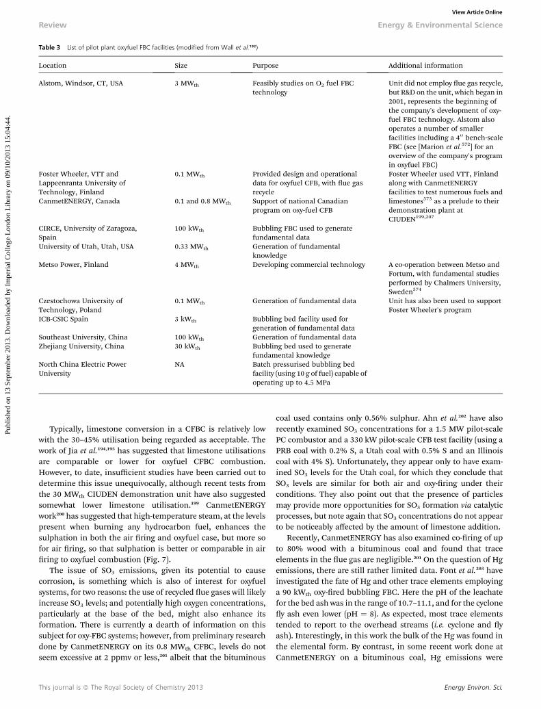
Table 3 List of pilot plant oxyfuel FBC facilities (modified from Wall et al.192)
Location Size Purpose Additional information
Alstom, Windsor, CT, USA 3 MWth Feasibly studies on O2 fuel FBCtechnology
Unit did not employ ue gas recycle,but R&D on the unit, which began in2001, represents the beginning ofthe company's development of oxy-fuel FBC technology. Alstom alsooperates a number of smallerfacilities including a 40 0 bench-scaleFBC (see [Marion et al.572] for anoverview of the company's programin oxyfuel FBC)
Foster Wheeler, VTT andLappeenranta University ofTechnology, Finland
0.1 MWth Provided design and operationaldata for oxyfuel CFB, with ue gasrecycle
Foster Wheeler used VTT, Finlandalong with CanmetENERGYfacilities to test numerous fuels andlimestones573 as a prelude to theirdemonstration plant atCIUDEN199,207
CanmetENERGY, Canada 0.1 and 0.8 MWth Support of national Canadianprogram on oxy-fuel CFB
CIRCE, University of Zaragoza,Spain
100 kWth Bubbling FBC used to generatefundamental data
University of Utah, Utah, USA 0.33 MWth Generation of fundamentalknowledge
Metso Power, Finland 4 MWth Developing commercial technology A co-operation between Metso andFortum, with fundamental studiesperformed by Chalmers University,Sweden574
Czestochowa University ofTechnology, Poland
0.1 MWth Generation of fundamental data Unit has also been used to supportFoster Wheeler's program
ICB-CSIC Spain 3 kWth Bubbling bed facility used forgeneration of fundamental data
Southeast University, China 100 kWth Generation of fundamental dataZhejiang University, China 30 kWth Bubbling bed used to generate
fundamental knowledgeNorth China Electric PowerUniversity
NA Batch pressurised bubbling bedfacility (using 10 g of fuel) capable ofoperating up to 4.5 MPa
Review Energy & Environmental Science
Publ
ishe
d on
13
Sept
embe
r 20
13. D
ownl
oade
d by
Im
peri
al C
olle
ge L
ondo
n L
ibra
ry o
n 09
/10/
2013
15:
04:4
4.
View Article Online
Typically, limestone conversion in a CFBC is relatively lowwith the 30–45% utilisation being regarded as acceptable. Thework of Jia et al.194,195 has suggested that limestone utilisationsare comparable or lower for oxyfuel CFBC combustion.However, to date, insufficient studies have been carried out todetermine this issue unequivocally, although recent tests fromthe 30 MWth CIUDEN demonstration unit have also suggestedsomewhat lower limestone utilisation.199 CanmetENERGYwork200 has suggested that high-temperature steam, at the levelspresent when burning any hydrocarbon fuel, enhances thesulphation in both the air ring and oxyfuel case, but more sofor air ring, so that sulphation is better or comparable in airring to oxyfuel combustion (Fig. 7).
The issue of SO3 emissions, given its potential to causecorrosion, is something which is also of interest for oxyfuelsystems, for two reasons: the use of recycled ue gases will likelyincrease SO3 levels; and potentially high oxygen concentrations,particularly at the base of the bed, might also enhance itsformation. There is currently a dearth of information on thissubject for oxy-FBC systems; however, from preliminary researchdone by CanmetENERGY on its 0.8 MWth CFBC, levels do notseem excessive at 2 ppmv or less,201 albeit that the bituminous
This journal is ª The Royal Society of Chemistry 2013
coal used contains only 0.56% sulphur. Ahn et al.202 have alsorecently examined SO3 concentrations for a 1.5 MW pilot-scalePC combustor and a 330 kW pilot-scale CFB test facility (using aPRB coal with 0.2% S, a Utah coal with 0.5% S and an Illinoiscoal with 4% S). Unfortunately, they appear only to have exam-ined SO3 levels for the Utah coal, for which they conclude thatSO3 levels are similar for both air and oxy-ring under theirconditions. They also point out that the presence of particlesmay provide more opportunities for SO3 formation via catalyticprocesses, but note again that SO3 concentrations do not appearto be noticeably affected by the amount of limestone addition.
Recently, CanmetENERGY has also examined co-ring of upto 80% wood with a bituminous coal and found that traceelements in the ue gas are negligible.201 On the question of Hgemissions, there are still rather limited data. Font et al.203 haveinvestigated the fate of Hg and other trace elements employinga 90 kWth oxy-red bubbling FBC. Here the pH of the leachatefor the bed ash was in the range of 10.7–11.1, and for the cycloney ash even lower (pH ¼ 8). As expected, most trace elementstended to report to the overhead streams (i.e. cyclone and yash). Interestingly, in this work the bulk of the Hg was found inthe elemental form. By contrast, in some recent work done atCanmetENERGY on a bituminous coal, Hg emissions were
Energy Environ. Sci.
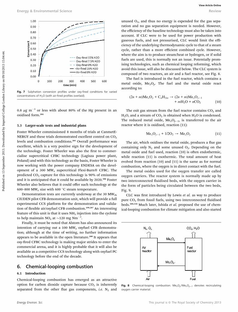
Fig. 7 Sulphation conversion profiles under oxy-fired conditions for variedconcentrations of H2O (with air-fired profiles overlaid).
Fig. 8 Chemical-looping combustion. MexOy/MexOy�1 denotes recirculatingoxygen carrier material.
Energy & Environmental Science Review
Publ
ishe
d on
13
Sept
embe
r 20
13. D
ownl
oade
d by
Im
peri
al C
olle
ge L
ondo
n L
ibra
ry o
n 09
/10/
2013
15:
04:4
4.
View Article Online
0.8 mg m�3 or less with about 80% of the Hg present in anoxidised form.204
5.3 Larger-scale tests and industrial plans
Foster Wheeler commissioned 8 months of trials at CanmetE-NERGY and these trials demonstrated excellent control on CO2
levels and combustion conditions.205 Overall performance wasexcellent, which is a very positive sign for the development ofthe technology. Foster Wheeler was also the rst to commer-cialise supercritical CFBC technology (Lagisza power plant,Poland) and with this technology as the basis, Foster Wheeler isnow working with the power company ENDESA on the devel-opment of a 300 MWe supercritical Flexi-Burn� CFBC. Thepredicted CO2 capture for this technology is 90% of emissionsand it is anticipated that it could be available by 2020.206 FosterWheeler also believes that it could offer such technology at the600–800 MWe size with 600 �C steam temperature.
Demonstration tests are currently underway at the 30 MWth
CIUDEN pilot CFB demonstration unit, which will provide a fullexperimental CCS platform for the demonstration and valida-tion of exible air/oxyfuel CFB combustion.199,207 An interestingfeature of this unit is that it uses NH3 injection into the cycloneto help maintain NOx at �120 mg Nm�3.
Finally, it must be noted that Alstom has also announced itsintention of carrying out a 100 MWe oxyfuel CFB demonstra-tion; although at the time of writing, no further informationappears to be available in the open literature.208 It appears thatoxy-red CFBC technology is making major strides to enter thecommercial arena, and it is highly probable that it will also beavailable as a competitive CCS technology along with oxyfuel PCtechnology before the end of the decade.
6. Chemical-looping combustion6.1 Introduction
Chemical-looping combustion has emerged as an attractiveoption for carbon dioxide capture because CO2 is inherentlyseparated from the other ue gas components, i.e. N2 and
Energy Environ. Sci.
unused O2, and thus no energy is expended for the gas sepa-ration and no gas separation equipment is needed. However,the efficiency of the baseline technology must also be taken intoaccount. If CLC were to be used for power production withgaseous fuels, and not pressurised, CLC would limit the effi-ciency of the underlying thermodynamic cycle to that of a steamcycle, rather than a more efficient combined cycle. However,where the aim is to produce steam/heat or hydrogen, or if solidfuels are used, this is normally not an issue. Potentially prom-ising technologies, such as chemical looping reforming, whichavoid this issue, will also be discussed below. The CLC system iscomposed of two reactors, an air and a fuel reactor, see Fig. 8.
The fuel is introduced in the fuel reactor, which contains ametal oxide, MexOy. The fuel and the metal oxide reactaccording to:
(2n + m)MexOy + CnH2m / (2n + m)MexOy�1
+ mH2O + nCO2 (10)
The exit gas stream from the fuel reactor contains CO2 andH2O, and a stream of CO2 is obtained when H2O is condensed.The reduced metal oxide, MexOy�1, is transferred to the airreactor where it is oxidised, reaction (11):
MexOy�1 + 1/2O2 / MexOy (11)
The air, which oxidises the metal oxide, produces a ue gascontaining only N2 and some unused O2. Depending on themetal oxide and fuel used, reaction (10) is oen endothermic,while reaction (11) is exothermic. The total amount of heatevolved from reaction (10) and (11) is the same as for normalcombustion, where the oxygen is in direct contact with the fuel.
The metal oxides used for the oxygen transfer are calledoxygen carriers. The reactor system is normally made up bytwo interconnected uidised beds, with the oxygen carrier inthe form of particles being circulated between the two beds,Fig. 9.
CLC was rst introduced by Lewis et al. as way to producepure CO2 from fossil fuels, using two interconnected uidisedbeds.209,210 Much later, Ishida et al. proposed the use of chem-ical-looping combustion for climate mitigation and also started
This journal is ª The Royal Society of Chemistry 2013
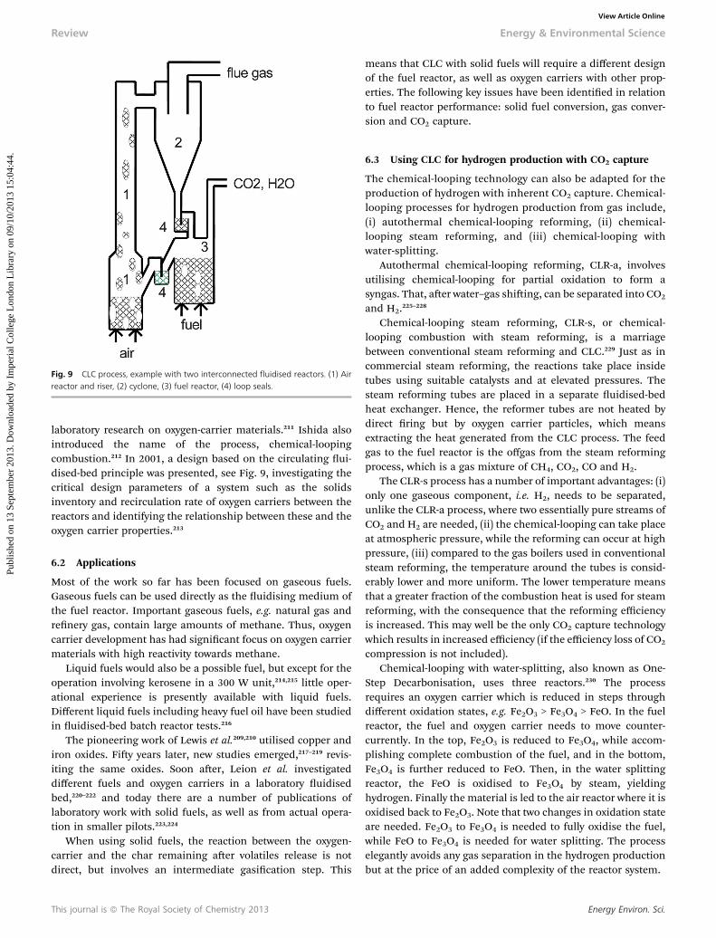
Fig. 9 CLC process, example with two interconnected fluidised reactors. (1) Airreactor and riser, (2) cyclone, (3) fuel reactor, (4) loop seals.
Review Energy & Environmental Science
Publ
ishe
d on
13
Sept
embe
r 20
13. D
ownl
oade
d by
Im
peri
al C
olle
ge L
ondo
n L
ibra
ry o
n 09
/10/
2013
15:
04:4
4.
View Article Online
laboratory research on oxygen-carrier materials.211 Ishida alsointroduced the name of the process, chemical-loopingcombustion.212 In 2001, a design based on the circulating ui-dised-bed principle was presented, see Fig. 9, investigating thecritical design parameters of a system such as the solidsinventory and recirculation rate of oxygen carriers between thereactors and identifying the relationship between these and theoxygen carrier properties.213
6.2 Applications
Most of the work so far has been focused on gaseous fuels.Gaseous fuels can be used directly as the uidising medium ofthe fuel reactor. Important gaseous fuels, e.g. natural gas andrenery gas, contain large amounts of methane. Thus, oxygencarrier development has had signicant focus on oxygen carriermaterials with high reactivity towards methane.
Liquid fuels would also be a possible fuel, but except for theoperation involving kerosene in a 300 W unit,214,215 little oper-ational experience is presently available with liquid fuels.Different liquid fuels including heavy fuel oil have been studiedin uidised-bed batch reactor tests.216
The pioneering work of Lewis et al.209,210 utilised copper andiron oxides. Fiy years later, new studies emerged,217–219 revis-iting the same oxides. Soon aer, Leion et al. investigateddifferent fuels and oxygen carriers in a laboratory uidisedbed,220–222 and today there are a number of publications oflaboratory work with solid fuels, as well as from actual opera-tion in smaller pilots.223,224
When using solid fuels, the reaction between the oxygen-carrier and the char remaining aer volatiles release is notdirect, but involves an intermediate gasication step. This
This journal is ª The Royal Society of Chemistry 2013
means that CLC with solid fuels will require a different designof the fuel reactor, as well as oxygen carriers with other prop-erties. The following key issues have been identied in relationto fuel reactor performance: solid fuel conversion, gas conver-sion and CO2 capture.
6.3 Using CLC for hydrogen production with CO2 capture
The chemical-looping technology can also be adapted for theproduction of hydrogen with inherent CO2 capture. Chemical-looping processes for hydrogen production from gas include,(i) autothermal chemical-looping reforming, (ii) chemical-looping steam reforming, and (iii) chemical-looping withwater-splitting.
Autothermal chemical-looping reforming, CLR-a, involvesutilising chemical-looping for partial oxidation to form asyngas. That, aer water–gas shiing, can be separated into CO2
and H2.225–228
Chemical-looping steam reforming, CLR-s, or chemical-looping combustion with steam reforming, is a marriagebetween conventional steam reforming and CLC.229 Just as incommercial steam reforming, the reactions take place insidetubes using suitable catalysts and at elevated pressures. Thesteam reforming tubes are placed in a separate uidised-bedheat exchanger. Hence, the reformer tubes are not heated bydirect ring but by oxygen carrier particles, which meansextracting the heat generated from the CLC process. The feedgas to the fuel reactor is the offgas from the steam reformingprocess, which is a gas mixture of CH4, CO2, CO and H2.
The CLR-s process has a number of important advantages: (i)only one gaseous component, i.e. H2, needs to be separated,unlike the CLR-a process, where two essentially pure streams ofCO2 and H2 are needed, (ii) the chemical-looping can take placeat atmospheric pressure, while the reforming can occur at highpressure, (iii) compared to the gas boilers used in conventionalsteam reforming, the temperature around the tubes is consid-erably lower and more uniform. The lower temperature meansthat a greater fraction of the combustion heat is used for steamreforming, with the consequence that the reforming efficiencyis increased. This may well be the only CO2 capture technologywhich results in increased efficiency (if the efficiency loss of CO2
compression is not included).Chemical-looping with water-splitting, also known as One-
Step Decarbonisation, uses three reactors.230 The processrequires an oxygen carrier which is reduced in steps throughdifferent oxidation states, e.g. Fe2O3 > Fe3O4 > FeO. In the fuelreactor, the fuel and oxygen carrier needs to move counter-currently. In the top, Fe2O3 is reduced to Fe3O4, while accom-plishing complete combustion of the fuel, and in the bottom,Fe3O4 is further reduced to FeO. Then, in the water splittingreactor, the FeO is oxidised to Fe3O4 by steam, yieldinghydrogen. Finally the material is led to the air reactor where it isoxidised back to Fe2O3. Note that two changes in oxidation stateare needed. Fe2O3 to Fe3O4 is needed to fully oxidise the fuel,while FeO to Fe3O4 is needed for water splitting. The processelegantly avoids any gas separation in the hydrogen productionbut at the price of an added complexity of the reactor system.
Energy Environ. Sci.
Energy & Environmental Science Review
Publ
ishe
d on
13
Sept
embe
r 20
13. D
ownl
oade
d by
Im
peri
al C
olle
ge L
ondo
n L
ibra
ry o
n 09
/10/
2013
15:
04:4
4.
View Article Online
There is also work with chemical-looping of solid fuelsdirected towards hydrogen production, rather than completecombustion, which is similar to the chemical-looping reformingand water-splitting processes proposed for gaseous fuels. Achemical-looping process for the production of syngas using solidfuels and two interconnected uidised beds was patented morethan 60 years ago.225 Some more recent processes involve usinglime to enhance fuel conversion to H2 by in situ CO2 removal, e.g.the Alstom Hybrid Combustion–Gasication Process and the GEFuel-Flexible Process.231 With respect to water-splitting, it shouldbe mentioned that going back 80–90 years, the main process forhydrogen production was the so-called steam-iron process. In thisprocess, iron oxide was reduced by coal to iron, and the iron wasthen reacted with steam to form hydrogen.231 Related processesthat are concerned with the direct production of hydrogenthrough water-splitting using Fe/FeO being studied today are theSyngas Chemical-Looping process (SCL) and the coal directchemical-looping process.231
6.4 Oxygen carrier materials
More than 900 different oxygen carrier materials have beenstudied in the laboratory,232 and there are several reviews coveringoxygen carrier materials,223,232,233 and discussing importantcriteria and the required thermodynamic properties.234 The rstphase of oxygen carrier development focussed mainly on fourmetal oxides: Ni, Fe, Mn and Cu. However, the development overthe last few years has been more diversied; there has been morework on combined metal oxides, on low-cost materials for usewith solid fuels, and on materials releasing oxygen, i.e. CLOUmaterials (see the following section).
Combined metal oxides, i.e. where two or more oxides arecombined not only physically, but also chemically, produce newoxides, for example, Cu0.95Fe1.05AlO4, Co0.5Ni0.5FeAlO4, CoFeAlO4,CuFeGaO4, NiFeAlO4.235 Some of these materials have the perov-skite structure, e.g. La1�xSrxFe1�yCoyO3�d, and Sr(Mn1�xNix)O3.236,237 Other types of oxide that should be mentioned arecombined Mn oxides with partial CLOU properties, i.e. with theability to release some oxygen. This includes Mn combined withCa, Mg, Ni and Fe.238–240 Many of these combined materials arepromising, but fewer have been successfully tested during actualoperation. An exception is CaMn0.875Ti0.125O3.241 Another isilmenite, FeTiO3, a naturally occurring low-cost combined oxidecommonly used with solid fuels.
Low-cost materials have been investigated mainly for usewith solid fuels, these studies include iron ore,242–244 manganeseore,245 ilmenite, CaSO4/CaS,246–253 industrial waste mate-rials,254,255 as well as comparisons of materials of differentsources.256,257 Most of the studies have used ilmenite,258–262
because it is a cheap ore, has a reasonably high reactivitytowards syngas and has shown good uidisation behaviour.
Most materials studied have only been investigated inlaboratory, but a signicant number of different materials haveactually been used in continuous operation in CLC pilots.These include oxides of nickel, copper, iron, manganese andcobalt, as well as natural minerals like ilmenite, iron ore andmanganese ore.
Energy Environ. Sci.
6.5 Chemical-looping with oxygen uncoupling (CLOU)
Chemical-Looping with Oxygen Uncoupling (CLOU) is closelyrelated to chemical-looping combustion but differs from CLCthrough the spontaneous release of oxygen in the fuel reactor. Forinstance, the CuO/Cu2O systemhas an equilibrium oxygen partialpressure of 0.02 bar at a temperature of 913 �C. This means that,at this temperature, the O2 concentration could be reduced downto a minimum of 2% in the air reactor, while oxygen could bereleased up to maximum 2% in the fuel reactor. As the presenceof fuel in the fuel reactor will consume oxygen released, a veryrapid release of oxygen is possible. CLOU using CuO has beenshown to work not only in laboratory batch uidised-bed testswith CuO and solid fuel,263,264 but also in continuous operationwith solid fuel.265 Also, combined manganese oxides have theability to release oxygen240 and successful operation with calciummanganates has been reported.241
6.6 Fluidised bed reactor system for CLC
In order to investigate uidised systems for CLC, a number ofstudies have utilised cold-ow modelling to identify stable andsuitable operating conditions for various designs.266–272
Actual operation in 12 CLC units of sizes 0.3 to 140 kWinvolving 29 oxygen-carrier materials was reported by Lyng-felt.273 The units are presented in Table 4, including eightadditional units. Thus, more than 4800 h of operation in20 units of sizes 0.5 to 140 kW, using a number of differentoxygen-carriers and fuels have been accomplished. Thisincludes more than 600 h in seven units using solid fuels. Thesuccessful operation in a number of small units with differentdesigns, different fuels, and different oxygen carriers, clearlydemonstrates that the process works and is viable, and thatthere are suitable oxygen-carrier materials for this newcombustion technology.
6.7 Modelling
For gaseous fuels, the main performance criterion is fuelconversion in the fuel reactor, and the work primarilyinvolves estimations of the required solids inventory to gaina given conversion to CO2, and its comparison to actualachievements.223,274–277
For solid fuels, the performance is more complex, and nor-mally three performance criteria are used, (i) solid fuelconversion, (ii) gas conversion and (iii) CO2 capture efficiency.These can essentially be modelled separately (as seen in publi-cations available).278–282
6.8 Conclusions for CLC
Although more development work is needed, it should bepointed out that the CLC technology provides unique advan-tages for avoiding the large costs and energy penalties inherentin gas separation. In the case of gaseous fuels, the followingconclusions can be made:
� The technology has been successfully demonstrated in anumber of smaller pilots and the technology should be ready toscale up to 1 or 10 MW size.
This journal is ª The Royal Society of Chemistry 2013
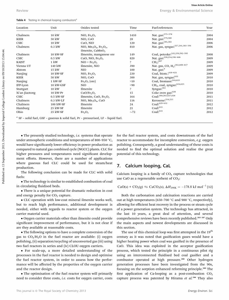
Table 4 Testing in chemical-looping combustorsa
Location Unit Oxides tested Time Fuel\references Year
Chalmers 10 kW NiO, Fe2O3 1410 Nat. gas\575–578 2004KIER 50 kW NiO, CoO 28 Nat. gas\579,580 2004CSIC 10 kW CuO, NiO 120 Nat. gas\581,582 2006Chalmers 0.3 kW NiO, Mn3O4, Fe2O3,
ilmenite, CaMnO3
810 Nat. gas, syngas\227,241,583–591 2006
Chalmers 10 kW-SF Ilmenite, manganese ore 149 Coal, petcoke\245,259,592–595 2008CSIC 0.5 kW CuO, NiO, Fe2O3 820 Nat. gas\228,254,596–606 2009KAIST 1 kW NiO + Fe2O3 ? CH4\
607 2009Vienna UT 140 kW Ilmenite, NiO 390 Nat. gas, CO, H2\
262,608–617 2009Alstom 15 kW NiO 100 Nat. gas\4 2009Nanjing 10 kW-SF NiO, Fe2O3 230 Coal, biom.\618–621 2009KIER 50 kW NiO, CoO 300 Nat. gas, syngas\622 2010Nanjing 1 kW-SF Fe2O3 (ore) >10 Coal, biomass\244,623 2010IFP-Lyon 10 kW-GSF NiO >90 CH4, coal, syngas\
624,625 2010Stuttgart 10 kW Ilmenite ? Syngas\261 2010Xi'an Jiaotong 10 kW-Pr CuO/Fe2O3 15 Coke oven gas\626 2010CSIC 0.5 kW-SF Ilmenite, CuO, Fe2O3 164 Coal\260,265,627,628 2011Chalmers 0.3 kW-LF NiO, Mn3O4, CuO 116 Kerosene\214,215 2011Chalmers 100 kW-SF Ilmenite 24 Coal\629–632 2012Hamburg 25 kW-SF Ilmenite 21 Coal\633 2012Ohio 25 kW-SF Fe2O3 �72 Coal\634 2012
a SF – solid fuel, GSF – gaseous & solid fuel, Pr – pressurised, LF – liquid fuel.
Review Energy & Environmental Science
Publ
ishe
d on
13
Sept
embe
r 20
13. D
ownl
oade
d by
Im
peri
al C
olle
ge L
ondo
n L
ibra
ry o
n 09
/10/
2013
15:
04:4
4.
View Article Online
� The presently studied technology, i.e. systems that operateunder atmospheric conditions and temperatures of 800–950 �C,would have signicantly lower efficiency in power production ascompared to natural gas combined cycle (NGCC) plants. CLC forhigher pressures and temperatures need signicant develop-ment efforts. However, there are a number of applicationswhere gaseous fuel CLC could be used for steam/heatproduction.
The following conclusion can be made for CLC with solidfuels:
� The technology is similar to established combustion of coalin circulating uidised beds.
� There is a unique potential for dramatic reduction in costand energy penalty for CO2 capture.
� CLC operation with low-cost mineral ilmenite works well,but to reach high performance, additional development isneeded, either with regards to reactor system or the oxygencarrier material used.
� Oxygen carrier materials other than ilmenite could providesignicant improvement of performance, but it is not clear ifare they available at reasonable costs.
� The following options to have a complete conversion of thegas to CO2/H2O in the fuel reactor are available: (i) oxygenpolishing, (ii) separation/recycling of unconverted gas (iii) usingtwo fuel reactors in series and (iv) CLOU oxygen carriers.
� For scale-up, a more detailed understanding of theprocesses in the fuel reactor is needed to design and optimisethe fuel reactor system, in order to assess how the perfor-mance will be affected by the properties of the oxygen carrierand the reactor design.
� The optimisation of the fuel reactor system will primarilyneed to consider three costs, i.e. costs for oxygen carrier, costs
This journal is ª The Royal Society of Chemistry 2013
for the fuel reactor system, and costs downstream of the fuelreactor to accommodate for incomplete conversion, e.g. oxygenpolishing. Consequently, a good understanding of these costs isneeded to nd the optimal solution and realise the greatpotential of this technology.
7. Calcium looping, CaL
Calcium looping is a family of CO2 capture technologies thatuse CaO as a regenerable sorbent of CO2:
CaO(s) + CO2(g) $ CaCO3(s), DH298K ¼ �178.8 kJ mol�1 (12)
Both the carbonation and calcination reactions are carriedout at high temperatures (650–700 �C and 900 �C, respectively),allowing for efficient heat recovery in the process or steam cycleof a power generation system. The technology has attracted, inthe last 10 years, a great deal of attention, and severalcomprehensive reviews have been recently published.283–287 Onlythe main aspects and newest developments are discussed inthis section.
The use of this chemical loop was rst attempted in the 19th
century as it was noted that gasication gases would have ahigher heating power when coal was gasied in the presence ofCaO. This idea was exploited in the acceptor gasicationprocess, which tested the principle in a continuous pilot rigusing an interconnected uidised bed coal gasier and acombustor operated at high pressure.288 Other hydrogengeneration processes have been investigated from the 90s,focusing on the sorption enhanced reforming principle.289 Therst application of Ca-looping as a post-combustion CO2
capture process was patented by Hirama et al.290 They also
Energy Environ. Sci.
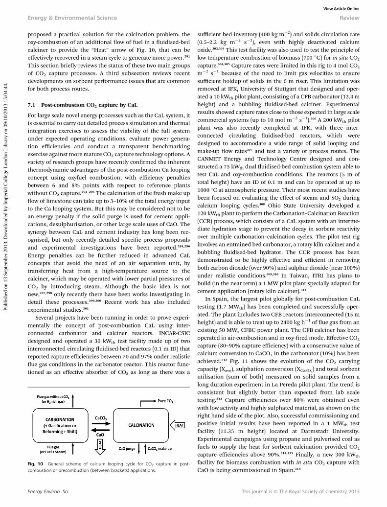
Energy & Environmental Science Review
Publ
ishe
d on
13
Sept
embe
r 20
13. D
ownl
oade
d by
Im
peri
al C
olle
ge L
ondo
n L
ibra
ry o
n 09
/10/
2013
15:
04:4
4.
View Article Online
proposed a practical solution for the calcination problem: theoxy-combustion of an additional ow of fuel in a uidised-bedcalciner to provide the “Heat” arrow of Fig. 10, that can beeffectively recovered in a steam cycle to generate more power.291
This section briey reviews the status of these two main groupsof CO2 capture processes. A third subsection reviews recentdevelopments on sorbent performance issues that are commonfor both process routes.
7.1 Post-combustion CO2 capture by CaL
For large scale novel energy processes such as the CaL system, itis essential to carry out detailed process simulation and thermalintegration exercises to assess the viability of the full systemunder expected operating conditions, evaluate power genera-tion efficiencies and conduct a transparent benchmarkingexercise against moremature CO2 capture technology options. Avariety of research groups have recently conrmed the inherentthermodynamic advantages of the post-combustion Ca-loopingconcept using oxyfuel combustion, with efficiency penaltiesbetween 6 and 8% points with respect to reference plantswithout CO2 capture.292–295 The calcination of the fresh make upow of limestone can take up to 3–10% of the total energy inputto the Ca looping system. But this may be considered not to bean energy penalty if the solid purge is used for cement appli-cations, desulphurisation, or other large scale uses of CaO. Thesynergy between CaL and cement industry has long been rec-ognised, but only recently detailed specic process proposalsand experimental investigations have been reported.284,296
Energy penalties can be further reduced in advanced CaLconcepts that avoid the need of an air separation unit, bytransferring heat from a high-temperature source to thecalciner, which may be operated with lower partial pressures ofCO2 by introducing steam. Although the basic idea is notnew,297,298 only recently there have been works investigating indetail these processes.299,300 Recent work has also includedexperimental studies.301
Several projects have been running in order to prove experi-mentally the concept of post-combustion CaL using inter-connected carbonator and calciner reactors. INCAR-CSICdesigned and operated a 30 kWth test facility made up of twointerconnected circulating uidised-bed reactors (0.1 m ID) thatreported capture efficiencies between 70 and 97% under realisticue gas conditions in the carbonator reactor. This reactor func-tioned as an effective absorber of CO2 as long as there was a
Fig. 10 General scheme of calcium looping cycle for CO2 capture in post-combustion or precombustion (between brackets) applications.
Energy Environ. Sci.
sufficient bed inventory (400 kg m�2) and solids circulation rate(0.5–2.2 kg m�2 s�1), even with highly deactivated calciumoxide.302,303 This test facility was also used to test the principle oflow-temperature combustion of biomass (700 �C) for in situ CO2
capture.304,305 Capture rates were limited in this rig to 4 mol CO2
m�2 s�1 because of the need to limit gas velocities to ensuresufficient holdup of solids in the 6 m riser. This limitation wasremoved at IFK, University of Stuttgart that designed and oper-ated a 10 kWth pilot plant, consisting of a CFB carbonator (12.4mheight) and a bubbling uidised-bed calciner. Experimentalresults showed capture rates close to those expected in large scalecommercial systems (up to 10 mol m�2 s�1).306 A 200 kWth pilotplant was also recently completed at IFK, with three inter-connected circulating uidised-bed reactors, which weredesigned to accommodate a wide range of solid looping andmake-up ow rates307 and test a variety of process routes. TheCANMET Energy and Technology Centre designed and con-structed a 75 kWth dual uidised-bed combustion system able totest CaL and oxy-combustion conditions. The reactors (5 m oftotal height) have an ID of 0.1 m and can be operated at up to1000 �C at atmospheric pressure. Their most recent studies havebeen focused on evaluating the effect of steam and SO2 duringcalcium looping cycles.308 Ohio State University developed a120 kWth plant to perform the Carbonation–Calcination Reaction(CCR) process, which consists of a CaL system with an interme-diate hydration stage to prevent the decay in sorbent reactivityover multiple carbonation–calcination cycles. The pilot test riginvolves an entrained bed carbonator, a rotary kiln calciner and abubbling uidised-bed hydrator. The CCR process has beendemonstrated to be highly effective and efficient in removingboth carbon dioxide (over 90%) and sulphur dioxide (near 100%)under realistic conditions.309,310 In Taiwan, ITRI has plans tobuild (in the near term) a 1 MW pilot plant specially adapted forcement application (rotary kiln calciner).311
In Spain, the largest pilot globally for post-combustion CaLtesting (1.7 MWth) has been completed and successfully oper-ated. The plant includes two CFB reactors interconnected (15 mheight) and is able to treat up to 2400 kg h�1 of ue gas from anexisting 50 MWe CFBC power plant. The CFB calciner has beenoperated in air-combustion and in oxy-redmode. Effective CO2
capture (80–90% capture efficiency) with a conservative value ofcalcium conversion to CaCO3 in the carbonator (10%) has beenachieved.312 Fig. 11 shows the evolution of the CO2 carryingcapacity (Xave), sulphation conversion (XCaSO4
) and total sorbentutilisation (sum of both) measured on solid samples from along duration experiment in La Pereda pilot plant. The trend isconsistent but slightly better than expected from lab scaletesting.313 Capture efficiencies over 80% were obtained evenwith low activity and highly sulphatedmaterial, as shown on theright hand side of the plot. Also, successful commissioning andpositive initial results have been reported in a 1 MWth testfacility (11.35 m height) located at Darmstadt University.Experimental campaigns using propane and pulverised coal asfuels to supply the heat for sorbent calcination provided CO2
capture efficiencies above 90%.314,315 Finally, a new 300 kWth
facility for biomass combustion with in situ CO2 capture withCaO is being commissioned in Spain.316
This journal is ª The Royal Society of Chemistry 2013
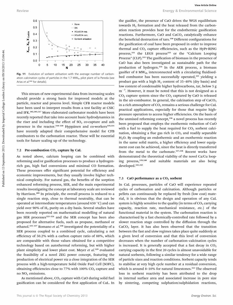
Fig. 11 Evolution of sorbent utilisation with the average number of carbon-ation–calcination cycles of particles in the 1.7 MWth pilot plant of la Pereda (seeArias et al.312 for details).
Review Energy & Environmental Science
Publ
ishe
d on
13
Sept
embe
r 20
13. D
ownl
oade
d by
Im
peri
al C
olle
ge L
ondo
n L
ibra
ry o
n 09
/10/
2013
15:
04:4
4.
View Article Online
This stream of new experimental data from increasing scalesshould provide a strong basis for improved models at theparticle, reactor and process level. Simple CFB reactor modelshave been used to interpret results from a test facility at CSICand IFK.302,303,317 More elaborated carbonator models have beenrecently reported that take into account basic hydrodynamics inthe riser and including the effect of SO2 co-capture and ashpresence in the reactor.318–320 Hyppanen and co-workers319,321
have recently adapted their comprehensive model for CFBcombustors to the carbonation reactor. These will be essentialtools for future scaling up of the technology.
7.2 Pre-combustion CO2 capture by CaL
As noted above, calcium looping can be combined withreforming and/or gasication processes to produce a hydrogen-rich gas, high fuel conversions and minimal CO formation.These processes offer signicant potential for efficiency andeconomic improvements, but they usually involve higher tech-nical complexity. For natural gas, the benets of the sorptionenhanced reforming process, SER, and the main experimentalresults investigating the concept at laboratory scale are reviewedby Harrison.289 In principle, the overall process is reduced to asingle reaction step, close to thermal neutrality, that can beoperated at intermediate temperatures (around 650 �C) and canyield over 90% of H2 purity on a dry basis. Several studies havebeen recently reported on mathematical modelling of naturalgas SER processes322–324 and the SER concept has been alsoproposed for alternative fuels, such as propane, methanol orethanol.325–327 Romano et al.328 investigated the potentiality of aSER process coupled to a combined cycle, calculating a netefficiency of 50.2% with a carbon capture ratio of 88%, whichare comparable with those values obtained for a competitivetechnology based on autothermal reforming, but with higherplant simplicity and lower plant cost. Meyer et al.329 evaluatedthe feasibility of a novel ZEG power concept, featuring theproduction of electrical power via a close integration of the SERprocess with a high-temperature Solid Oxide Fuel Cell (SOFC),obtaining efficiencies close to 77% with 100% CO2 capture andno NOx emissions.
As mentioned above, CO2 capture with CaO during solid fuelgasication can be considered the rst application of CaL. In
This journal is ª The Royal Society of Chemistry 2013
the gasier, the presence of CaO drives the WGS equilibriumtowards H2 formation and the heat released from the carbon-ation reaction provides heat for the endothermic gasicationreactions. Furthermore, CaO and CaCO3 catalytically enhancethe benecial destruction of tars.330 Different congurations forthe gasication of coal have been proposed in order to improvethermal and CO2 capture efficiencies, such as the HyPr-RINGprocess,331 the LEGS process332 or the “Calcium LoopingProcess” (CLP).333 The gasication of biomass in the presence ofCaO has also been investigated as sustainable path for theproduction of hydrogen.334 In the AER process, a biomassgasier of 8 MWth interconnected with a circulating uidised-bed combustor has been successfully operated,335 yielding aproduct gas with a high H2 content of 35–40% (dry basis) andlow content of condensable higher hydrocarbons, tar, below 5 gm�3. However, it must be noted that this is not designed as aCO2 capture system since the CO2 captured by CaO is releasedin the air-combustor. In general, the calcination step of CaCO3
in a rich atmosphere of CO2 remains a serious challenge for CaLpractical applications, especially for those that require high-pressure operation to access higher efficiencies. On the basis ofthe unmixed reforming concept,336 a novel process has recentlybeen proposed that employs the exothermic reduction of CuOwith a fuel to supply the heat required for CO2 sorbent calci-nation, obtaining a ue gas rich in CO2 and readily separableH2O. By coupling an endothermic and an exothermic reactionin the same solid matrix, a higher efficiency and lower equip-ment cost can be achieved, since the heat is directly transferredfrom the metal to the carbonate.337,338 Recent works havedemonstrated the theoretical viability of the novel Ca/Cu loop-ing process,339,340 and suitable materials are also beingdeveloped.341,342
7.3 CaO performance as a CO2 sorbent
In CaL processes, particles of CaO will experience repeatedcycles of carbonation and calcination. Although particles orpellets can continuously be replaced by fresh (low cost) mate-rial, it is obvious that the design and operation of any CaLsystem is highly sensitive to the quality (in terms of CO2 carryingcapacity, reaction rate, mechanical resistance, etc.) of thefunctional material in the system. The carbonation reaction ischaracterised by a fast chemically-controlled rate followed by aslower reaction stage controlled by the diffusion through theCaCO3 layer. It has also been observed that the transitionbetween the fast and slow regimes takes place quite suddenly ata given level of conversion and that this level of conversiondecreases when the number of carbonation–calcination cyclesis increased. It is generally accepted that a fast decay in CO2
carrying capacity in the rst 20 cycles is almost unavoidable fornatural sorbents, following a similar tendency for a wide rangeof particle sizes and reaction conditions. Sorbent capacity tendsto stabilise at very high cycle number at a residual conversion,which is around 8–10% for natural limestones.313 The observedloss in sorbent reactivity has been attributed to the dropin internal surface area and associated increase in pore sizeby sintering, competing sulphation/sulphidation reactions,
Energy Environ. Sci.
Energy & Environmental Science Review
Publ
ishe
d on
13
Sept
embe
r 20
13. D
ownl
oade
d by
Im
peri
al C
olle
ge L
ondo
n L
ibra
ry o
n 09
/10/
2013
15:
04:4
4.
View Article Online
attrition of the sorbent and the subsequent elutriation of nes,and by ash fouling. It is noteworthy that even when fullydegraded in reactivity, CaO from natural limestone still takes up�0.16 g CO2 per gram, a high value compared to many otherpotential sorbents. The thickness of the carbonate layer formedon the free internal surfaces of CaO is a critical parameter toexplain the end of the fast reaction period. However, someimportant phenomena are not well explained by this simpletheory, such as the temperature dependency of the CO2 carryingcapacity and steam effects,343 which can be very signicant.344 Liet al.345 have recently provided an elegant carbonation reactionrate model that seems to be able to explain most observationsusing a mechanism well established for other gas–solid reac-tions: they model the CaCO3 growth as islands on the CaOsurface. The fast carbonation stage is completed when theseislands merge. With the increase of reaction temperature, thesizes and heights of the CaCO3 product island increases whilethe island density decreases. Only a few parameters are neededto t the observed carbonation rate curves in a wide range oftemperatures. The calcination reaction of highly cycled particlesin a CaL is assumed to be very fast, but this has only recentlybeen conrmed experimentally.346 Sulphation rates of CaO inCaL reactors (carbonator or calciner) are also a recent subject ofinvestigation. The large make-up ow of fresh limestone char-acteristic of most CaL systems allows for lower CaSO4 content inthe system than in equivalent desulphurisation units usingCaO. Open pore structures of the sorbent in a CaL can also alterthe rate and the extent of sulphation. Arias et al.347 reportedsulphation kinetics of CaO particles at low levels of conversionto CaSO4, whilst Anthony and co-workers348 focused theirinvestigations on the performance of synthetic Ca-basedsorbents. Attrition is another important issue in CaL because itaffects capture efficiency, sorbent cost and operational cost.Particles have been shown to break up mainly during the rstcalcination. In addition, attrition has been found to be highlysensitive to limestone choice.349,350
Several approaches have been investigated to improve initialsorbent properties and/or reactivate spent sorbents, but manystill require detailed studies at the process level to ensure theirviability for large-scale commercial applications. Lisbonaet al.351 studied the integration of the sorbent cost and itscarrying capacity and mechanical performance for differentoptions applied to an existing coal-red power plant. Theydemonstrated that the optimum CO2 carrying capacity thatinvolves minimal heat requirements in the calciner is relativelymodest (at around 20% of Ca conversion). However, for pre-combustion applications higher activities may be desirable. Ingeneral, R&D activity continues on the main techniquesexplored for sorbent improvement: hydration,352–354
doping,283,284,287,355 thermal pre-activation,283,286 and syntheticsorbents.286,287 Low cost methods based on co-precipitation canyield synthetic sorbents with high melting points and acarbonation conversion above 75% aer 50 cycles.356,357 The useof supports like alumina358 or cements containing CaO andAl2O3
359, 360 have recently been shown to improve the durabilityof CaO sorbent (some of them above 0.50 g g�1 sorbent aer 30carbonation–calcination cycles under severe calcination
Energy Environ. Sci.
conditions).361 A different method for reactivation has also beenproposed recently:362 a small regeneration reactor (recarbona-tor) is added between the carbonator and calciner vessels tore-carbonate the particles leaving the carbonator (calcination–carbonation–recarbonation cycles) using a small ow of pureCO2 from the calciner's off-gas. The slight increase in thecarbonate conversion in each cycle sustains the residual activityat around 0.15 to 0.2, which is close to the optimum designtarget for post-combustion systems.
8. Low temperature adsorbents
A large number of adsorbents have been recently proposed andinvestigated as possible candidates for carbon capture at lowtemperature. The selection of the best samples cannot be basedonly on their adsorption properties (i.e. capacity, heat ofadsorption, kinetics) because other factors may play a crucialrole in the overall process. For this reason, economic criteriahave to always be taken into account, not only with regards tothe costs of synthesis but also to the size of the equipment (i.e.the volume of the adsorbent needed); the regeneration energydemand (i.e. the heat of adsorption); the cycle time (i.e. equi-librium and kinetic properties and process selected, pressure orvacuum swing adsorption (PSA or VSA) vs. temperature swingadsorption (TSA)); the hydrothermal stability; the loss ofperformances due to the presence of impurities in the feedstream.
Based on these observations the best adsorbent should havehigh CO2 capacity at low pressure, high selectivity for CO2, fastadsorption/desorption kinetics, good mechanical properties,high hydrothermal and chemical stability, as well as low costs ofsynthesis.
Zeolites, as well as carbon-based materials, are the mostwidely investigated classes of adsorbents. In recent years aconsiderable research effort has been put in the development ofa new class of adsorbent, MOFs (metal–organic frameworks), aspromising candidates for CO2 separation. In addition, a largevariety of functionalised (mostly amine-based) adsorbents hasbeen recently produced. The very encouraging results obtainedare opening a new eld for the investigation of new possibleadsorbents for carbon capture applications.
8.1 Zeolites
Zeolites are crystalline aluminosilicates characterised by ahighly ordered open structure. They can differ greatly for theframework type, the size and shape of the channels and cages aswell as the Si/Al ratio. With regard to carbon capture applica-tions, type X and A zeolites have been widely investigated.363
They are generally characterised by a relatively high CO2
capacity at low pressure, which makes them very promisingcandidates for CO2 separation from ue gases.364–371 Generally13X is indicated as the best candidate for post combustion PSAapplications with values of the CO2 uptake between 2 and 3 molkg�1 at 0.1 bar, at temperatures between 15 and 35 �C. Despitethe relative high heat of adsorption (36–37 kJ mol�1),364,368 thehigh working capacity and selectivity make zeolite 13X one of
This journal is ª The Royal Society of Chemistry 2013
Review Energy & Environmental Science
Publ
ishe
d on
13
Sept
embe
r 20
13. D
ownl
oade
d by
Im
peri
al C
olle
ge L
ondo
n L
ibra
ry o
n 09
/10/
2013
15:
04:4
4.
View Article Online
the best choice for CO2 capture from ue gas streams.364,365,368,369
For this reason 13X is generally used as a benchmark materialfor low-temperature adsorbents for carbon captureapplications.
Despite the good adsorption properties for CO2, zeolites aregenerally highly hydrophilic; the presence of water induces analteration of the electric eld reducing the strength of interac-tion between the quadrupole of CO2 and the cations, resultingin a lower uptake.372,373 Detailed studies on the effect of thepresence of small amounts of water on the CO2 uptake ofzeolites were presented by Brandani and Ruthven372,373 and,more recently by Li et al.374 and Lee et al.,375 concluding that thepresence of even very small amount of water greatly reduces theadsorption performance of zeolites.
The nature and the distribution of the cations inside the zeoliteframework play a crucial role in the nal CO2 adsorption proper-ties. Their presence not only inducesmodications of the electricaleld inside the pores, but it can also change the morphologicalstructure of the zeolites, inuencing the adsorption kinetics.Ideally, the higher charge density of the smaller cations shouldincrease the electrostatic interaction between the CO2 and thecations, resulting in a higher uptake. This trend of the CO2 uptakewith the increasing charge density has been observed by severalauthors.375–379 Deviations from the expected trend have also beenreported for some types of zeolites due to the high basicity of theframework, which has a predominant role relative to the strengthof the quadrupole interaction.380,381On the other hand, the size, theposition and the grade of occupancy of the extra-framework cationsmay be responsible for hindering diffusion of CO2 due to theblockage of the windows of the structure by the cations.376 In thisregard, an interesting case is represented by the Rho zeolites, forwhich the presence of extra-framework cations has been proved toinduce considerable distortions in the structure.382–387 A recentstudy of Lozinska et al.379 reported that the combination of theframework distortion and the hindering effect of the cationsresulted in an extremely slow diffusion of CO2 (measured using theZLC technique). In addition, a gating effect was detected for the Na-Rho type due to the presence of CO2, similarly to what reported byPalomino et al.378
8.2 MOFs
The structure of MOFs consists of organic–inorganic hybridnetworks formed by metal ligand bonds.388 One of their mainattractive features is the possibility to modify their structuresand functional properties by changing the building blocks usedin their construction: this gives the incredible advantage ofnely controlling pore dimension, shape of the channels, andchemical potential of the surface, which ultimately gives thepossibility to build adsorbents with the desired adsorptionproperties.389 MOFs generally show higher CO2 capacity at highpressures compared to zeolites, but, despite their relatively lowcapacity at low partial pressures, their high thermal stabilityand the fully reversible CO2 adsorption make them very prom-ising materials for pressure-swing processes.390,391 With regardto the low pressure applications, MOF-74 and its politypes haveshown attractive features for carbon capture. The trend of the
This journal is ª The Royal Society of Chemistry 2013
CO2 uptake follows the sequence, Mg > Ni � Co > Zn, withvalues of the CO2 capacity for Mg-MOF-74 being almost doublethan that for 13X.389,392–394 Mg-MOF-74 is characterised by a highselectivity for CO2
395 and the heat of adsorption is generallyhigher than the one of zeolites with values of about 47 and 41 kJmol�1 for theMg and Ni form respectively.389,393,396,397 The higherionic character of the Mg–O bond improves the affinity withCO2, but on the other hand, it makes the Mg form morehydrophilic than the analogous Ni form. Studies to comparethe effect of water on CO2 adsorption for Ni-MOF-74 andcommercial zeolites were performed by LeVan et al.;391 althoughthe CO2 capacity was found to reduce in presence of water for allthe materials, the effect was less pronounced for Ni-MOF-74.Liu et al.398 reported that the H2Omolecules interact specicallywith the strong adsorption sites of Ni-MOF-74, causing a non-recoverable loss of CO2 capacity. An extensive study on differentMOF-74 samples (Zn-, Co-, Ni- and Mg-MOF-74) was carried outby Hu394 at the conditions of interest for post-combustioncarbon capture at 38 �C and 0.1 bar using the ZLCmethod. Testsin the presence of impurities (water, SOx and NOx) showed asignicant deactivation of the samples with the Ni-MOF-74demonstrating a greater resistant to degradation.
8.3 Carbon-based adsorbents
Carbon-based adsorbents are synthesised by the thermaldecomposition of carbonaceous materials and have beeninvestigated and used for a wide range of gas separations. Sir-iwardane et al.,399 compared the adsorption properties ofcommercial activated carbon with 13X and 4A. From the study,it emerged that, relative to the zeolites, activated carbon showeda lower uptake and selectivity at lower pressures, but theymaintained higher hydrothermal stability. Values of the heat ofadsorption are generally lower for the activated carbons than forother adsorbents with values in the range from 15 to 30 kJmol�1.399–402
Shen et al.403,404 investigated the use of activated carbon in aVPSA process to capture CO2 from ue gas, obtaining relativelyhigh values for the recovery and purity of CO2. The possibility ofapplication of carbon molecular sieves in a PSA process for CO2
from ue gas was recently investigated by Carruthers et al.402
The study concluded that despite the lower capacity relative toother adsorbents the low heats of adsorption and the stability ofcarbon-based adsorbents make them competitive for CO2
capture from ue gas.The adsorption properties of activated carbon can be
signicantly improved by the incorporation of amine functionalgroups into their porous structure. The CO2 chemically reactswith the amine groups forming bicarbonate and/or carba-mate,405,406 which is promoted at higher temperatures. As aresult, an increase of the CO2 capacity is observed at highertemperatures while at lower temperatures, physisorption ispredominant and the loss of porosity due to the amine func-tionalisation has a crucial role in the nal CO2 uptake.406
Moreover, relatively slow kinetics are generally observed.405
As part of the carbon based materials new developments arein progress with regard to the carbon nanotubes (CNT) for
Energy Environ. Sci.
Energy & Environmental Science Review
Publ
ishe
d on
13
Sept
embe
r 20
13. D
ownl
oade
d by
Im
peri
al C
olle
ge L
ondo
n L
ibra
ry o
n 09
/10/
2013
15:
04:4
4.
View Article Online
low-pressure carbon capture. Multi-walled CNT functionalisedwith APTES have shown a signicant improvement of the CO2
uptake compared to the pristine sample.407–409
8.4 Mesoporous silicas
Mesoporous silicas are generally characterised by low CO2
uptake due to the weak surface interaction with CO2 molecules.What makes them attractive for carbon capture is the possibilityto introduce functional groups (usually amine-based groups) toincrease the affinity with CO2. The advantage of having largeand uniform pores is that it is possible to introduce surfacemodication, reducing possible steric hindrance of theadsorption sites. As a result of the introduction of functionalgroups, a signicant increase of CO2 uptake at low pressure hasbeen shown compared to the pure silica; very promising resultshave been obtained recently, but the increased complexity of theadsorption process may, in some cases, lead to an over-estimation of the adsorption capacity.410 The adsorption prop-erties are mostly inuenced by the density of amine active sitesand by the accessibility to the sites (pore size).411
Belmabkhout et al.412–414 induced a series of modications onMCM-41: they synthesised a pore-expanded form (PE-MCM-41)and successively introduced amine groups in the expandedform (TRI-PE-MCM-41). The PE-MCM-41 exhibited a higher CO2
uptake at high pressure than the non-modied MCM-41;however, there was not a signicant improvement in the lowconcentration region. On the other hand, the TRI-PE-MCM-41sample, which combined the advantages of a large pore struc-ture due to the presence of amine groups, showed a dramaticimprovement of the adsorption capacity, especially in the lowpressure region. The value of the CO2 uptake at 0.1 bar and25 �C was comparable with the one of a typical zeolite, 13X(2.2 mol kg�1). Even though the capacity is comparable with13X, the amine-modied sample exhibited a signicantincrease of the CO2 uptake in presence of water, which is a veryimportant advantage for the possible application of the samplefor CO2 capture applications. Xu et al.415,416 studied theadsorption performances of PEI-impregnated MCM-41 underdifferent conditions, reporting an increase of the CO2 capacitywith the PEI loading and temperature (with amaximum at 75 �Cfor the sample with 75 wt% of PEI), while the adsorptionprocess was found to be strongly kinetically controlled.
8.5 Pilot-plants development and testing
At present, a few pilot scale demonstrations are investigatingthe effectiveness of low temperature adsorbents for CO2
capture. One of the rst pilot plant projects was the CO2CRC H3project417 lignite-red power plant based at International Pow-er's Hazelwood Power Plant, and was commissioned in 2009Latrobe Valley, Victoria, Australia. The research project wascompleted in 2011 and the performance of commercial andnovel adsorbents was investigated at high humidity levels in thepresence of SOx and NOx with a 3-bed multi-layered vacuumswing adsorption process. Multi-layered adsorbents were usedto remove, rst, the water and subsequently SOx/NOx from theue gas. A layer of CO2-selective materials was then added. A
Energy Environ. Sci.
purity of about 71% and a recovery of about 60% were achievedaer continuous running of the process using a simple 6-stepcycle (without purge) for a week.
The Science and Engineering Research Council (SERC) ofSingapore in 2009 launched a research programme on CarbonCapture and Utilisation (CCU), which includes a collaborativeproject418 between the adsorption and process systems researchgroups at National University of Singapore (NUS), NanyangTechnological University (NTU) and Institute of Chemical andEngineering Sciences (ICES). A pilot plant that was designedbased on the results from a detailed simulation study, has beenconstructed. 1 m long columns with 0.3 m internal diameterwere used and the plant is expected to capture around 3 tCO2
madsorbent�3 per day using a simple 4-step Vacuum Swing
Adsorption (VSA) with Zeochem 13X and synthetic dry ue gas.Special attention is focused on the power consumption by thevacuum pumps so that a reliable estimate of the energy penaltymay be obtained.
Based on a lab scale 1 kWplant with supported amine sorbentsin a circulating uidised bed developed by ADA EnvironmentalSolutions, the US DOE419,420 has funded a 1 MW pilot plant. Thepilot plant will be located in the Southern Company – Alabamapower Co. plant and should be completed by the end of 2013.
Inventys claims that their VeloxoTherm�421 process cancapture CO2 for 15 US$ t�1. The technology involves an inten-sied temperature swing adsorption process with structuredadsorbent and steam regeneration in a rotating adsorbentwheel. ETI422 just announced the award of £20 million fundingfor a 5 MW project that can be used for a new-build CCGT orretrotted onto one. The consortium will be led by Inventys withHowden, MAST Carbon International and Doosan PowerSystems as partners, as well as Rolls Royce for specialist engi-neering support. The initial stage of the project is labscale studies, but the nal aim is to have a commercial tech-nology by 2020.
The ATMI/SRI BrightBlack423microporous carbonwas recentlytested at a coal-red steam production facility operated by theUniversity of Toledo in Ohio, USA. The test results were presentedin Pittsburgh, Pennsylvania, USA at the 2012 NETL CO2 CaptureTechnology Meeting. The material exceeded the DOE targetsof >90% CO2 capture with >90% CO2 purity during tests with200 standard l min�1 of ue gas. Additionally, the columnoperated for approximately 7000 adsorption–regeneration cycleswith no loss in process or adsorbent performance and no signs ofadsorbent degradation. The project partners are now looking atscaling up to pilot scale testing.
Not much information is available at the moment on thepilots due to the early stages of development of most of them;the availability of data on these projects in the future willrepresent a crucial step towards the deployment of adsorptionprocesses at commercial scale.
Having reviewed a number of technologies for carboncapture from industrial and power station sources, this articlewill now focus on more long-term options. This will includecarbon capture from the ambient atmosphere, CO2 utilisationand mineralisation.
This journal is ª The Royal Society of Chemistry 2013
Review Energy & Environmental Science
Publ
ishe
d on
13
Sept
embe
r 20
13. D
ownl
oade
d by
Im
peri
al C
olle
ge L
ondo
n L
ibra
ry o
n 09
/10/
2013
15:
04:4
4.
View Article Online
9. Direct air capture technology9.1 Introduction
Direct air capture is the process of removing CO2 from the airand generating a concentrated stream of CO2 for sequestrationor re-use. It belongs to a group of technologies referred to asnegative emissions, or carbon dioxide removal (CDR) technol-ogies. Other negative emissions technologies include bioenergyenhanced carbon capture and storage (BECCS); augmentedocean disposal (or ocean liming); biochar production and uti-lisation; the dispersion of naturally occurring bases such asserpentine and olivine across the land; and the enhancement ofbiological CO2 sinks such as reforestation, afforestation andaquatic biomass via ocean fertilisation. These technologies arebeyond the scope of this paper, though the interested readermay refer to a recent techno-economic analysis of negativeemissions technologies by McGlashan et al. for more informa-tion.424 In fact, we will only very briey review recent develop-ments in air capture technologies here.
Compared with traditional CO2 capture from concentratedpoint sources; direct air capture offers a number of purportedadvantages. Firstly, air capture provides a means of adjustingthe atmospheric CO2 concentration in the increasingly morelikely event that mitigation efforts fall short of targets and theatmospheric greenhouse gas inventory reaches dangerous levelsor takes a trajectory towards stabilisation at dangerous levels.Air capture could also offer an option for addressing CO2
emissions from mobile and distributed sources, such as vehi-cles, fuel use in buildings and geographically isolated industry,where direct capture and integration into a centralised CCSnetwork would be either impractical and/or uneconomical.Furthermore, direct air capture technology could be installed bystorage site operators to manage fugitive emissions from theCCS network and leakage from geological formations. In addi-tion, it has been suggested that direct air capture technologycould potentially be situated anywhere, such as deserts, waste-land and the ocean, provided there is access to an availableenergy source and sequestration sites. However, there are alsosignicant disadvantages to the technology. Removing andconcentrating CO2 from air at �390 ppm to a pure stream(>90%) implies a greater energy input, and treatment of a vastlygreater volume of gas than CO2 capture from concentratedpoint sources. For example, the thermodynamic minimumenergy required to extract CO2 from ambient air is�20 kJ mol�1
compared with 8.4 kJ mol�1 and 5.3 kJ mol�1 to capture andconcentrate CO2 from the ue gases of natural gas-, and coal-red power stations containing 5% and 15% CO2 respectively at65 �C. Furthermore, the actual energy consumed by air capturetechnology will be signicantly larger than the thermodynamicminimum, as is the case for CCS systems. Zeman et al. esti-mated that the energy demand of a large-scale MEA-basedprocess for CO2 capture from concentrated sources would be181 kJ mol�1, which is far greater than the thermodynamicminimum energy requirement.425
Direct air capture has been practiced on a small scale fordecades for the purpose of maintaining safe levels of CO2 insubmarines426 and spaceships427 though it is important to note
This journal is ª The Royal Society of Chemistry 2013
that the concentration of CO2 is in these locations is signi-cantly higher than that within the atmosphere. CO2 must alsobe removed from air prior to air liquefaction to avoid opera-tional issues associated with dry ice formation.428 However, thevolume of air that must be handled to capture comparableamounts of CO2 to traditional CCS technologies is far greater.This has signicant implications on energy consumption andthe required plant size. As a consequence, capture technologiesthat require pre-processing of air, such as drying, heating,cooling or pressurising will not be economical.429 This rules outtechnologies typically used for small-scale air capture such asmembrane separation (large pressure gradients and multiplepasses required to achieve a high-purity CO2 stream);430 cryo-genic separation (cooling and compression required); andzeolite, activated carbon and alumina-based molecular sieves(adversely affected by moisture and low adsorption capacities atambient conditions). Two main approaches have beenproposed for direct air capture (i) wet air capture systems and(ii) dry air capture systems. Whilst both capture processesrequire energy to regenerate the sorbent, the energy demandscales proportionally to the mass of CO2 captured as opposed tothe volume of air processed. For those seeking more informa-tion than this brief overview, the reader is encouraged to read arecent review by Goeppert et al.431
9.2 Wet air capture systems-the soda/lime process
The most developed approach for wet air capture is the soda/lime process.431 This uses aqueous sodium hydroxide (NaOH)-based solutions to extract CO2 from ambient air in a packed-column,432 convection tower433 or spray-tower contactorsystem.434 Aer the contactor, the NaOH solution is regeneratedvia caustic recovery (or causticisation), where slaked lime (anaqueous solution of Ca(OH)2) is reacted with the dissolvedsodium carbonate (Na2CO3) product to form a calciumcarbonate (CaCO3) precipitate mud. The CaCO3 mud is ltered,dried and transferred to a rotary kiln where it is calcined attemperatures in excess of 900 �C to produce a concentratedstream of CO2 and a calcium oxide (CaO) powder. TheCaO powder is then dissolved in water to regenerate the slakedlime solution.
The requirement of substantial thermal energy for limeregeneration represents a signicant drawback of this process.Baciocchi et al. estimated that process energy demands arelikely to range between 7.6 and 11.6 GJ tCO2
�1 (334–510 kJ molCO2
�1) with drying, pre-heating and calcining of the CaCO3
accounting for the majority of the total energy demand.435 Otherenergy intensive processes considered in the Baciocchi et al.estimates were CO2 compression and air separation to produceO2 for an oxyfuel kiln. As a consequence, CO2 abatement costsfor this process are high, typically quoted as 240–500 US$ tC�1
(65–136 US$ tCO2�1);436 much higher than some estimated cost
of CCS at 30–50 US$ tCO2�1 437 (some authors of this paper
might suggest a more conservative range of costs, from$50–$120 tCO2
�1 depending upon source and capture tech-nology). Recent papers by the American Physical Society438 andHouse et al.439 have stated costs may be even higher, in the
Energy Environ. Sci.
Energy & Environmental Science Review
Publ
ishe
d on
13
Sept
embe
r 20
13. D
ownl
oade
d by
Im
peri
al C
olle
ge L
ondo
n L
ibra
ry o
n 09
/10/
2013
15:
04:4
4.
View Article Online
region of US$600 and US$1000 per ton of CO2 respectively,though it should be noted that these costings are disputed byresearchers within the air capture community.429,440
9.3 Alternative wet air capture systems
In attempts to eliminate the energy intensive lime regenerationstep, the paper and pulping industry have been developing andpiloting an alternative approach that involves direct caustici-sation with titanates.441 The energy required to regenerate tita-nanates is much lower than for CaO; 90 kJ mol�1 compared to179 kJ mol�1.
9.4 Dry air capture systems
Dry air capture systems typically employ solid organoamine-based adsorbents where amine functional groups are eitherphysically or chemically bound to the surface of a porous-silica;carbon, metal oxide; or polymer support.442 Much of the work todate has focused on developing sorbents with high CO2 capac-ities and has neglected to use realistic desorption conditions,opting instead for desorption at elevated temperatures in aninert gas stream generating a dilute CO2 stream. Lackner et al.have developed an alternative material for extracting CO2 fromambient air, comprising of an anionic ion-exchange resin withquaternary amine functionality dispersed onto a polypropylenemembrane.443 The positive charge associated with the quater-nary amines is balanced by mobile hydroxyl or carbonatecounter-ions, which adsorb CO2 when dry, and release CO2
when wet. Desorption can be achieved via either contacting thematerial with a humidied gas stream or directly with water. Aircapture costs for a system employing this adsorbent have beenestimated by the purveyors as 15 US$ tCO2
�1 with initial costsincluding infrastructure and maintenance costs of 200 US$tCO2
�1. It is considered by a number of the authors of thisarticle that these costs are unrealistic, on the basis of highlycontentious assumptions concerning mass production andautonomous operation. A simple analysis by Brandani indicatesthat the cost of air capture relative to CO2 capture from a powerstation should be around a factor of ten higher.444
9.5 Conclusions and future scope
Laboratory scale research has demonstrated that direct aircapture is technically feasible. Wet air capture is the mostdeveloped approach. However, the high energy requirementsfor sorbent regeneration, particularly in the case of the soda/lime process, has led to very high estimated mitigation costs.Some progress has been made towards reducing the energydemand associated with sorbent regeneration through the useof alternative causticising agents and other improvements;however, further work is required to address and manage issuesassociated with high energy requirements, heat integration,large evaporative losses during liquid–air contacting and thehigh corrosivity of the strong-base absorbents solutions.
At present, the future of large-scale direct air capture as aclimate change mitigation technology remains uncertain. Aircapture R&D is still in its infancy, far behind the moreconventional climate change mitigation technologies. Cost
Energy Environ. Sci.
estimates vary substantially ranging from as low as 20 US$tCO2
�1 to as high as 1000 US$ tCO2�1 and it is highly likely that
air capture will offer one of the most expensive options formitigating climate change. For this reason, other, cheaperoptions for addressing climate change such as reducing thecarbon intensity of electricity generation through efficiencysavings in existing power plants, increased deployment ofrenewable energy technologies, nuclear power and CCS shouldbe aggressively pursued before air capture is considered. Ulti-mately, commercial deployment of air capture technology willdepend on whether the technology can be proven on a largescale and at a cost that makes it protable to do so. For this tobe realised, the future carbon price must also be high, i.e.morethan the cost of extracting and storing atmospheric CO2.
10. Retrofitting CCS to power stations – thecase for flexible operation10.1 Introduction
The aim of this section is to review the recent literature per-taining to the retrotting of post-combustion CO2 capturetechnology to fossil fuel-red power stations and then discussthe impact of this retrot on the merit order of such a deca-rbonised power station. The temporal, economic and policycontext of this discussion is in that of the UK in the 2030s wherethe current electricity market reform445 (EMR) discussion hasbeen completed and there are signicant amounts of inter-mittent renewable power446 in the UK energy system. Oneimportant target is that of having 15% of the UK's energysupplied by renewable resources by 2020.446
At the time of writing (early 2013), the UK is undergoing anEMR exercise which is intended to create a policy environmentconducive to sufficiently de-risk the capital investment associ-ated with the installation of new power generation capacity tosupport investment by the international capital markets in UKpower generation, and avoid the foreseen energy gap if thisinvestment is not made.
From the perspective of a potential investor, risk is associ-ated with the probability and magnitude of an unfavourableoutcome (e.g. prot below expectations). Taking prot as simplythe difference between annualised revenue and cost, in thecontext of a power station, and it is a function of:
� Electricity price (feeding into a revenue stream).� Load factor and dispatch frequency (how much and how
oen a power plant can sell energy to the grid).� Annualised capital cost (a function of the initial installed
cost, payback time and discount rate).� Fuel cost.� Carbon cost.However, given that one will typically select a payback time
and discount rate such that 80% of the original investment ispaid back within 10 years,447,448 carbon prices are likely to bemandated by the EMR (at least in the UK, although there maybe somemarket element to this as well) and electricity prices areessentially pegged to fuel prices (gas in the UK), the mainsources of risk associated with investing in a power plant, withor without CCS, are the load factor, dispatch frequency, fuel and
This journal is ª The Royal Society of Chemistry 2013
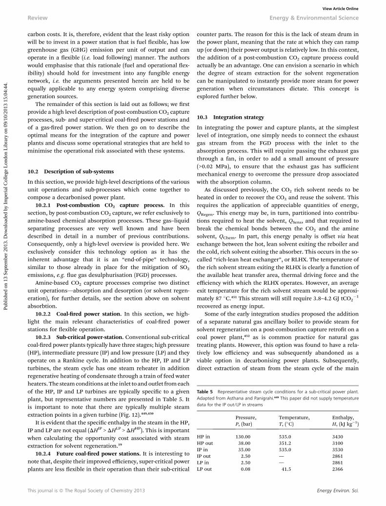
Review Energy & Environmental Science
Publ
ishe
d on
13
Sept
embe
r 20
13. D
ownl
oade
d by
Im
peri
al C
olle
ge L
ondo
n L
ibra
ry o
n 09
/10/
2013
15:
04:4
4.
View Article Online
carbon costs. It is, therefore, evident that the least risky optionwill be to invest in a power station that is fuel exible, has lowgreenhouse gas (GHG) emission per unit of output and canoperate in a exible (i.e. load following) manner. The authorswould emphasise that this rationale (fuel and operational ex-ibility) should hold for investment into any fungible energynetwork, i.e. the arguments presented herein are held to beequally applicable to any energy system comprising diversegeneration sources.
The remainder of this section is laid out as follows; we rstprovide a high level description of post-combustion CO2 captureprocesses, sub- and super-critical coal-red power stations andof a gas-red power station. We then go on to describe theoptimal means for the integration of the capture and powerplants and discuss some operational strategies that are held tominimise the operational risk associated with these systems.
Table 5 Representative steam cycle conditions for a sub-critical power plant.Adapted from Asthana and Panigrahi.449 This paper did not supply temperaturedata for the IP out/LP in streams
Pressure,P, (bar)
Temperature,T, (�C)
Enthalpy,H, (kJ kg�1)
HP in 130.00 535.0 3430HP out 38.00 351.2 3100IP in 35.00 535.0 3530IP out 2.50 — 2861LP in 2.50 — 2861LP out 0.08 41.5 2366
10.2 Description of sub-systems
In this section, we provide high-level descriptions of the variousunit operations and sub-processes which come together tocompose a decarbonised power plant.
10.2.1 Post-combustion CO2 capture process. In thissection, by post-combustion CO2 capture, we refer exclusively toamine-based chemical absorption processes. These gas–liquidseparating processes are very well known and have beendescribed in detail in a number of previous contributions.Consequently, only a high-level overview is provided here. Weexclusively consider this technology option as it has theinherent advantage that it is an “end-of-pipe” technology,similar to those already in place for the mitigation of SO2
emissions, e.g. ue gas desulphurisation (FGD) processes.Amine-based CO2 capture processes comprise two distinct
unit operations—absorption and desorption (or solvent regen-eration), for further details, see the section above on solventabsorbtion.
10.2.2 Coal-red power station. In this section, we high-light the main relevant characteristics of coal-red powerstations for exible operation.
10.2.3 Sub-critical power-station. Conventional sub-criticalcoal-red power plants typically have three stages; high pressure(HP), intermediate pressure (IP) and low pressure (LP) and theyoperate on a Rankine cycle. In addition to the HP, IP and LPturbines, the steam cycle has one steam reheater in additionregenerative heating of condensate through a train of feed waterheaters. The steamconditions at the inlet to andoutlet fromeachof the HP, IP and LP turbines are typically specic to a givenplant, but representative numbers are presented in Table 5. Itis important to note that there are typically multiple steamextraction points in a given turbine (Fig. 12).449,450
It is evident that the specic enthalpy in the steam in the HP,IP and LP are not equal (DHIP > DHLP > DHHP). This is importantwhen calculating the opportunity cost associated with steamextraction for solvent regeneration.19
10.2.4 Future coal-red power stations. It is interesting tonote that, despite their improved efficiency, super-critical powerplants are less exible in their operation than their sub-critical
This journal is ª The Royal Society of Chemistry 2013
counter parts. The reason for this is the lack of steam drum inthe power plant, meaning that the rate at which they can rampup (or down) their power output is relatively low. In this context,the addition of a post-combustion CO2 capture process couldactually be an advantage. One can envision a scenario in whichthe degree of steam extraction for the solvent regenerationcan be manipulated to instantly provide more steam for powergeneration when circumstances dictate. This concept isexplored further below.
10.3 Integration strategy
In integrating the power and capture plants, at the simplestlevel of integration, one simply needs to connect the exhaustgas stream from the FGD process with the inlet to theabsorption process. This will require passing the exhaust gasthrough a fan, in order to add a small amount of pressure(>0.02 MPa), to ensure that the exhaust gas has sufficientmechanical energy to overcome the pressure drop associatedwith the absorption column.
As discussed previously, the CO2 rich solvent needs to beheated in order to recover the CO2 and reuse the solvent. Thisrequires the application of appreciable quantities of energy,QRegen. This energy may be, in turn, partitioned into contribu-tions required to heat the solvent, QSens, and that required tobreak the chemical bonds between the CO2 and the aminesolvent, QChem. In part, this energy penalty is offset via heatexchange between the hot, lean solvent exiting the reboiler andthe cold, rich solvent exiting the absorber. This occurs in the so-called “rich-lean heat exchanger”, or RLHX. The temperature ofthe rich solvent stream exiting the RLHX is clearly a function ofthe available heat transfer area, thermal driving force and theefficiency with which the RLHX operates. However, an averageexit temperature for the rich solvent stream would be approxi-mately 87 �C.451 This stream will still require 3.8–4.2 GJ tCO2
�1
recovered as energy input.Some of the early integration studies proposed the addition
of a separate natural gas ancillary boiler to provide steam forsolvent regeneration on a post-combustion capture retrot on acoal power plant,452 as is common practice for natural gastreating plants. However, this option was found to have a rela-tively low efficiency and was subsequently abandoned as aviable option in decarbonising power plants. Subsequently,direct extraction of steam from the steam cycle of the main
Energy Environ. Sci.
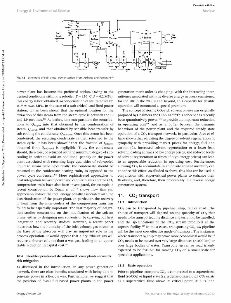
Fig. 12 Schematic of sub-critical power station. From Asthana and Panigrahi.449
Energy & Environmental Science Review
Publ
ishe
d on
13
Sept
embe
r 20
13. D
ownl
oade
d by
Im
peri
al C
olle
ge L
ondo
n L
ibra
ry o
n 09
/10/
2013
15:
04:4
4.
View Article Online
power plant has become the preferred option. Owing to thedesired conditions within the reboiler (T¼ 120 �C, P¼ 0.2MPa),this energy is best obtained via condensation of saturated steamat P z 0.25 MPa. In the case of a sub-critical coal-red powerstation, it has been shown that the optimal location for theextraction of this steam from the steam cycle is between the IPand LP turbines.453 As before, one can partition the contribu-tions to QRegen into that obtained by the condensation ofsteam, QCond, and that obtained by sensible heat transfer bysub-cooling the condensate, QSub-cool. Once this steam has beencondensed, the resulting condensate is then returned to thesteam cycle. It has been shown19 that the fraction of QRegen
obtained from QSub-cool is negligible. Thus, the condensateshould, therefore, be returned with theminimum degree of sub-cooling in order to avoid an additional penalty on the powerplant associated with returning large quantities of sub-cooledliquid to steam cycle. Specically, the condensate should bereturned to the condensate heating train, as opposed to thepower cycle condenser.453 More sophisticated approaches toheat integration between power and capture plants and the CO2
compression train have also been investigated, for example, arecent contribution by Duan et al.454 shows how this canappreciably reduce the total energy penalty associated with thedecarbonisation of the power plant. In particular, the recoveryof heat from the inter-coolers of the compression train wasfound to be especially important. The vast majority of integra-tion studies concentrate on the modication of the solventphase, either by designing new solvents or by carrying out heatintegration and recovery studies. However, a recent paperillustrates how the humidity of the inlet exhaust gas stream atthe base of the absorber will play an important role in theprocess operation. It would appear that a dry exhaust gas willrequire a shorter column than a wet gas, leading to an appre-ciable reduction in capital cost.18
10.4 Flexible operation of decarbonised power plants – towardsrisk mitigation
As discussed in the introduction, in any power generationnetwork, there are clear benets associated with being able togenerate power in a exible way. Furthermore, we suggest thatthe position of fossil fuel-based power plants in the power
Energy Environ. Sci.
generation merit order is changing. With the increasing inter-mittency associated with the diverse energy network envisionedfor the UK in the 2030's and beyond, this capacity for exibleoperation will command a special premium.
The concept of storing CO2-rich solvent on-site was originallyproposed by Chalmers and Gibbins.455 This concept has recentlybeen quantitatively proven456 to provide an important reductionin operating cost456 and as a buffer between the dynamicbehaviour of the power plant and the required steady stateoperation of a CO2 transport network. In particular, Arce et al.have shown that adjusting the degree of solvent regeneration insympathy with prevailing market prices for energy, fuel andcarbon (i.e. increased solvent regeneration or a lower leansolvent loading at times of low energy prices, and reduced levelsof solvent regeneration at times of high energy prices) can leadto an appreciable reduction in operating cost. Furthermore,allowing CO2 to accumulate in an on-site solvent inventory canenhance this effect. As alluded to above, this idea can be used inconjunction with super-critical power plants to enhance theirexibility, and, therefore, their protability in a diverse energygeneration system.
11. CO2 transport11.1 Introduction
CO2 can be transported by pipeline, ship, rail or road. Thechoice of transport will depend on the quantity of CO2 thatneeds to be transported, the distance and terrain to be travelled,and the specications of the CO2 stream produced at thecapture facility.457 In most cases, transporting CO2 via pipelinewill be the most cost effective mode of transport. The instanceswhere transport by ship may prove more economical would be ifCO2 needs to be moved over very large distances (>1000 km) orover large bodies of water. Transport via rail or road is onlyexpected to be feasible for moving CO2 on a small scale forspecialist applications.
11.2 Basic operation
Prior to pipeline transport, CO2 is compressed to a supercriticaluid (sc-CO2) or liquid state (i.e. a dense-phase uid). CO2 existsas a supercritical uid above its critical point, 31.1 �C and
This journal is ª The Royal Society of Chemistry 2013
Review Energy & Environmental Science
Publ
ishe
d on
13
Sept
embe
r 20
13. D
ownl
oade
d by
Im
peri
al C
olle
ge L
ondo
n L
ibra
ry o
n 09
/10/
2013
15:
04:4
4.
View Article Online
74 bar. This is the most efficient phase for transporting CO2 bypipeline as it has both the high density of a liquid and thefavourable ow characteristics of a gas. However, it is notpossible to maintain pipeline temperatures above the criticaltemperature in all situations. It is, therefore, important toensure pressures drops are managed and pipeline pressures arekept above vapour–liquid equilibrium conditions to maintain asingle-dense-phase ow and avoid liquid slugs and otheroperational problems that may eventuate if conditions fallwithin the region where a two-phase (gas–liquid) ow mayoccur. Operating pressures of existing CO2 pipelines are in therange of 85 to 210 bar where CO2 is a dense-phase uid over awide range of temperatures. To maintain sufficiently highpressures over long distances, intermediate pumping (orbooster) stations are required at certain intervals along thepipeline. For shorter distances, booster stations may be avoidedby increasing the pipeline inlet pressure; however, more energywould be consumed for compression and thicker walled pipe-line would be required.
In terms of CO2 transport by ship, it is most efficient totransport CO2 as a cryogenic liquid. Aspelund et al. has calcu-lated optimum conditions for CO2 transport by ship of 6.5 barand �51.2 �C.458 Large scale liquefaction would primarilyinvolve cooling via compression and expansion of the feed gas.Some loss of CO2 is expected as a consequence of boil off andthe ship's emissions would be in the region of 3 to 4% per1000 km.457 Losses can be minimised by utilising a refrigeratedcontainer ship or by re-capturing and liquefying the boil-off gas.
Ship-based transport systems require intermediate storagefacilities, and the equipment and infrastructure for loading andunloading CO2 at the loading docks, and storage sites to linkcontinuous production of CO2 at capture facilities with discretetransport of CO2 by ship.
Ships are more exible than pipelines as they are able totransport CO2 in volumes far below the design capacity. Shipstherefore offer the potential to collect CO2 from multiple siteson the way to the storage site and can better adapt to uctua-tions in the CO2 production rate of the emitter.
11.3 Existing experience
Globally, there is approximately 6000 km of pipeline infra-structure in operation for CO2 transportation purposes, most ofwhich is based in the US and Canada for transporting CO2 tosites for enhanced oil recovery (EOR).459 At present, most of theCO2 used for EOR is sourced from natural deposits, thoughthere are a few projects utilising CO2 from anthropogenicsources. Table 6 provides a summary of the major long-distanceCO2 pipelines currently operating. There is also limited opera-tional experience of onshore and offshore pipelines trans-porting CO2, derived from natural gas production, forsequestration in saline aquifers at the Snøhvit LNG facility,Sleipner, and In Salah.
Ship-based CO2 transport experience is far more limited. Atpresent, there are only four small ships, transporting food-gradeCO2 in northern Europe.457 Anthony Veder Group operates therst purpose-built CO2 tanker, which can ship up to 1825
This journal is ª The Royal Society of Chemistry 2013
tonnes of CO2 at �40 �C and 18 barg. Yara International char-ters the other three ships which have capacities between 900and 1200 tCO2
�1.191,460 Work is on-going to develop ships withthe capacities required for large-scale CCS deployment. Maerskare currently working on pressurised, semi-refrigerated CO2
tankers with capacities up to 45 000 tonnes.461
11.4 Pipeline design and operation considerations
CO2 pipelines must be designed and constructed at an optimalcost in such a way that they are reliable and safe to operate,posing minimal risk to local populations and the environ-ment.462 Pipeline design is primarily inuenced by the requiredthroughput and hydrodynamic properties of the CO2, such asdensity, phase behaviour, viscosity and compressibility. There-fore, factors affecting the hydrodynamic properties of CO2,including temperature, pressure, ow rate and composition,need to be modelled and characterised as part of the designprocess. The presence of impurities, particularly water, may alsolead to operational problems concerning corrosion, gas hydrateand ice formation. As a consequence, pipeline entry specica-tions are set in order to minimise or even avoid these problems.
11.4.1 CO2 specications. CO2 from natural sources issaturated with water and typically composed of 98.372–98.350%CO2; 1.521–0.136% N2; 0.107–1.514% CH4 and trace amounts ofH2S.462 Therefore apart from dehydration, minimal gas treat-ment is required. Anthropogenic CO2 on the other hand, tendsto be much less pure, containing other impurities such as CO,O2, H2S, SOx, NOx and H2. Amines, NH3, methanol and glycolsmay also be present as a consequence of CO2 capture, dehy-dration and corrosion control. The exact levels will varydepending on the source, capture process and gas treatmentsteps.
The level of impurities that can be tolerated will depend onthe storage method (or end use) and the transportationmethod.EOR specications tend to be strict (Table 7) as certain impu-rities will have detrimental effects on the process. In the case ofEOR, there is an economic incentive to remove certain impu-rities down to very low levels and design CO2 specications foroptimum oil recovery efficiency. However, transporting CO2 forstorage purposes does not share this relationship and removingimpurities in anthropogenic CO2 down to very low levelsimposes a signicant energy and cost penalty on the process.Therefore, CO2 specications for storage purposes will mostlikely be determined on the basis of cost-benet analyses,regulatory and legislative requirements, and health and safetyconsiderations.
A few studies have attempted to dene CO2 specications fortransport and storage purposes. The Dynamis project463 upda-ted specications that were initially proposed for pre-combus-tion CO2 capture technologies as part of the ENCAP project464 totake into account safety and toxicity limits. As a consequence,allowable levels of H2S, CO, SOx and NOx gases have been low-ered in accordance with their short term exposure limits(STELs). To meet these specications, additional gas treatmentmeasures such as regenerative absorption columns may berequired in addition to the standard SOx and NOx removal
Energy Environ. Sci.
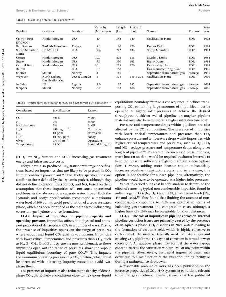
Table 6 Major long-distance CO2 pipelines465,467
Pipeline Operator LocationCapacity[Mt per year]
Length[km]
Pressure[bar] Source Purpose
Startyear
Canyon Reef(SACROC)
Kinder Morgan USA 4.4 352 140 Gasication Plant EOR 1972
Bati Raman Turkish Petroleum Turkey 1.1 90 170 Dodan Field EOR 1983Sheep MountainNorth
BP AMOCO USA 9.2 772 132 Sheep Mountain EOR 1983
Cortez Kinder Morgan USA 19.3 803 186 McElmo Dome EOR 1984Bravo Kinder Morgan USA 7.3 350 165 Bravo Dome EOR 1984Central Basin Kinder Morgan USA 20 278 170 Denver City Hub EOR 1985Bairoil — USA 8.3 180 — Gas manufacturing plant EOR 1986Snøhvit Statoil Norway 1 160 — Separation from natural gas Storage 1996Weyburn North Dakota
Gasication Co.USA & Canada 5 328 186 & 204 Gasication Plant EOR 2000
In Salah BP Algeria 1.0 17 185 Separation from natural gas Storage 2004Sleipner Statoil Norway 0.7 153 100 Separation from natural gas Storage 2006
Table 7 Typical entry specification for CO2 pipelines serving EOR operations635
Constituent Specication Reason
CO2 >95% MMPN2 4% MMPHydrocarbons 5% MMPH2O 480 mg m�3 CorrosionO2 10 ppm CorrosionH2S 10–200 ppm SafetyGlycol 0.4 ml m�3 OperationsTemperature 65 �C Material integrity
Energy & Environmental Science Review
Publ
ishe
d on
13
Sept
embe
r 20
13. D
ownl
oade
d by
Im
peri
al C
olle
ge L
ondo
n L
ibra
ry o
n 09
/10/
2013
15:
04:4
4.
View Article Online
(FGD, low NOx burners and SCR), increasing gas treatmentenergy and infrastructure costs.
Ecofys have also produced CO2 transport/storage specica-tions based on impurities that are likely to be present in CO2
from a coal-red power plant.465 The Ecofys specications aresimilar to those dened by the Dynamis project, although theydid not dene tolerance limits for SOx and NOx based on theirassumption that these impurities will not cause operationalproblems in the absence of a separate water phase. Both theDynamis and Ecofys specications recommend a maximumwater level of 500 ppm to avoid precipitation of a separate waterphase, which has been identied as the main factor inuencingcorrosion, gas hydrate and ice formation.
11.4.2 Impact of impurities on pipeline capacity andoperating pressure. Impurities affects the physical and trans-port properties of dense-phase CO2 in a number of ways. Firstly,the presence of impurities opens out the range of pressureswhere vapour and liquid CO2 exist in equilibrium. Impuritieswith lower critical temperatures and pressures than CO2, suchas H2, N2, CH4, O2, CO and Ar, are the most problematic as theseimpurities open out the range of pressures above the vapourliquid equilibrium boundary of pure CO2.465 This impactsthe minimum operating pressure of a CO2 pipeline, which mustbe increased with increasing impurity content to avoid two-phase ows.
The presence of impurities also reduces the density of dense-phase CO2, particularly at conditions close to the vapour–liquid
Energy Environ. Sci.
equilibrium boundary.465,466 As a consequence, pipelines trans-porting CO2 containing large amounts of impurities must beoperated at higher inlet pressures to achieve the desiredthroughput. A thicker walled pipeline or tougher pipelinematerial may also be required at a higher infrastructure cost.
Pressure and temperature drops within pipelines are alsoaffected by the CO2 composition. The presence of impuritieswith lower critical temperatures and pressures than CO2
enhance pressure and temperature drops whilst impurities withhigher critical temperatures and pressures, such as H2S, SO2
and NO2, reduce pressure and temperature drops along a setlength of pipeline.467 To account for increased pressure drops,more booster stations would be required at shorter intervals tokeep the pressure sufficiently high to maintain a dense-phaseow. However, adding more booster station substantiallyincreases pipeline infrastructure costs, and in any case, thisoption is not feasible for subsea pipelines. Alternatively, thepipeline would have to be operated at a higher inlet pressure.
Yan et al. carried out a cost-benet analysis to determine theeffect of removing typical non-condensable impurities found inanthropogenic CO2 (N2, H2, O2 and CH4) to different levels (1%,4% and 10%).468 They found that limiting the amount of non-condensable compounds to <4% was optimal in terms ofbalancing gas treatment and compression costs, although ahigher limit of <10% may be acceptable for short distances.
11.4.3 The role of impurities in pipeline corrosion. Internalpipeline corrosion issues are primarily caused by the presenceof an aqueous phase. CO2 dissolves in “free water” leading tothe formation of carbonic acid, which is highly corrosive tocarbon steel (the material typically used for natural gas andexisting CO2 pipelines). This type of corrosion is termed “sweetcorrosion”. An aqueous phase may form if the water vapourcontent exceeds the saturation vapour level at any point withinthe pipeline. Alternatively, accidental ingress of water mayoccur due to a malfunction at the gas conditioning facility orduring a maintenance shutdown.
A reasonable amount of work has been published on thecorrosive properties of CO2–H2O systems at conditions relevantto natural gas pipelines; however, there is far less published
This journal is ª The Royal Society of Chemistry 2013
Review Energy & Environmental Science
Publ
ishe
d on
13
Sept
embe
r 20
13. D
ownl
oade
d by
Im
peri
al C
olle
ge L
ondo
n L
ibra
ry o
n 09
/10/
2013
15:
04:4
4.
View Article Online
research at conditions relevant to CO2 pipeline transport.Corrosion rates are dependent on the operating conditions,including pressure, temperature, water vapour content, owrate, steel composition and exposure time. The presence ofother impurities will also inuence corrosion rates. Corrosionrates as high as 20 mm per year have been reported for carbonsteel exposed to water-saturated CO2 at relatively high temper-atures and pressures, although the literature is not in generalagreement, with different authors reporting signicantlydifferent corrosion rates at quite similar conditions.469,470 Theprimary cause of these discrepancies is most likely due to thedifferences in the ow rates, exposure time, material-to-watersurface areas, and steel composition used by different researchinstitutions.
Investigations into the corrosion mechanisms have foundthat under stagnant conditions, corrosion rates are initially fastbut decrease with increasing exposure time.471 This is due toformation of a protective iron carbonate (FeCO3) product layer/scale that precipitates out of the aqueous phase once it becomessupersaturated with iron. Product layer formation is inhibitedunder free owing conditions as mobile aqueous phases areless likely to become supersaturated with iron. Furthermore, inthe case where a protective layer has formed, the frictionalforces of the owing gas are likely to cause destabilisation orremoval of the protective lm, which could lead to severelocalised corrosion.
Corrosion can still occur in the absence of a distinct aqueousphase; however, rates are much lower due to the rapid precip-itation of a protective FeCO3 scale. In this case, corrosion andscale formation is most likely due to the formation of residualor transient aqueous phases, or stabilised aqueous surfacelms.
The presence of other impurities complicates matterssomewhat as certain impurities will interact in the presence ofan aqueous phase to enhance, or in a few cases hinder, internalcorrosion within a CO2 transport system.472 Of particularconcern are SOx, NOx and O2, which react with water to formsulphuric or nitric acid. O2 will also react with FeCO3 scales toform oxides and hydroxides which are not protective. Theseacids along with other acidic impurities that may be present inanthropogenic CO2 such as HCl (a common impurity in uegases from coal power stations), will act to further reduce thepH of any aqueous phases that have formed. The solubility ofFeCO3 is increased at the lower pH values, rendering theformation of an iron carbonate protective layer unlikely, thusenhancing the induced corrosion rate. Furthermore, sulphuricand nitric acids can form in the vapour phase, even at very lowwater vapour contents of <200 ppm, causing notable corrosionin the absence of a distinct aqueous phase.471 Ruhl et al. foundthat HNO3 and HCl were the most mobile in supercritical CO2,causing the highest corrosion rates. H2SO4 on the other hand,appeared to be much less mobile and did not cause signicantcorrosion in the absence of an aqueous phase.473 On the otherhand, the presence of basic impurities such as glycols, NH3 andamines such as MEA will have the opposite effect on the pH ofan aqueous phase and thus hinder corrosion. In fact, glycols arecommonly used corrosion inhibitors in natural gas pipelines.
This journal is ª The Royal Society of Chemistry 2013
Experience from the petrochemical industry has found thatH2S will also cause corrosion. At partial pressures <0.0035 bar,H2S interacts with carbon steel in the presence of an aqueousphase to form iron sulphide.465 As is the case with FeCO3, FeScan precipitate onto the surface of the carbon steel, forming aprotective layer that inhibits further corrosion. However, H2S atpartial pressures >0.0035 bar can cause “sour corrosion” (orsour cracking), primarily via sulphide stress induced cracking(SSIC) and hydrogen induced cracking (HIC). It has also beenreported that the presence of CO in CO2–H2O mixtures cancause transgranular stress cracking corrosion. Cracking corro-sion is particularly problematic as it can lead to material failurewithin a timescale of days.
Impurities may also affect the solubility of water in CO2. Afew accounts suggest that the presence of CH4 and otherhydrocarbons reduce the water solubility of CO2,474 whilst H2Shas the opposite effect.463 At present, published research con-cerning the effect of impurities on the water solubility of dense-phase CO2 is very limited. More work is required to investigatethe effects of anthropogenic CO2 impurities on corrosion andthe water solubility of dense-phase CO2 at a greater range ofconditions relevant to CO2 transport.
11.4.4 Gas hydrate and ice formation. In addition tocorrosion, the presence of water may also lead to operationalproblems concerning gas hydrate and ice formation. Gashydrates are solids with similar properties to ice that can causeblockages in the pipeline and compressors. The publishedresearch concerning hydrate formation in CO2 transportsystems is limited. It is generally reported that hydrates canform at CO2 pipelines conditions; however, the extent of hydrateformation is minimal if water levels are controlled in line withindustry accepted standards.463 Chapoy et al. determined thathydrate formation in a pure CO2–H2O system could be avoidedby limiting the water content to <250 ppm at conditions of�2 to30 �C and up to 200 bar.474 Further work is required to deter-mine the effects other common impurities have on gas hydrateformation.
11.4.5 Dening water level specications for CO2 trans-port. Current industry-accepted water level specications typi-cally range between 288 and 480 mg m�3 (�150–250 ppm),475
but many operators are opting for an even more conservativespecications of <50 ppm, in which CO2 is considered fullydehydrated.463 To meet these specications, a two-stage dryingprocess is required, in which water is rst removed down to400–500 ppm using standard vapour–liquid separator drums,followed by secondary drying on regenerative amine or glycol-based absorption columns.476 Corrosion data from 12 years ofoperational experience on the SACROC pipeline showed thatcorrosion rates were limited to between 0.5 and 2.5 mm year�1
by imposing a <50 ppm water level entry specication.475
Rogers and Mayhew dened the threshold water vapourlimit, below which corrosion and other water related issues aredeemed negligible, as <60% relative humidity.477 Others havedened threshold water limits between 300 and 600 ppm.463,475
Kinder Morgan, the largest CO2 pipeline operator, species amaximum water level of 640 ppm.465 Considering water can beremoved down to 400–500 ppm in vapour–liquid separator
Energy Environ. Sci.
Energy & Environmental Science Review
Publ
ishe
d on
13
Sept
embe
r 20
13. D
ownl
oade
d by
Im
peri
al C
olle
ge L
ondo
n L
ibra
ry o
n 09
/10/
2013
15:
04:4
4.
View Article Online
drums, a 400–600 ppm water level limit seems appropriate.Furthermore, this is well below the 60% relative humiditythreshold at typical pipeline operating conditions (0–50 �C and85–200 bar), where the minimum water solubility of dense-phase CO2 is �1500 ppm.478 However, it is likely that moreconservative water level requirements may have to be speciedwhen transporting CO2 containing high concentrations of NOx,H2S and CH4. Furthermore, water level specications for shiptransport will be less exible owing to the lower operatingtemperature. Water level specications will most likely remainat <50 ppm to avoid gas hydrate and ice formation duringcompression and liquefaction.476
11.4.6 Material considerations. Operational experience todate, which amounts to over 40 years, has demonstrated thatcarbon steels are suitable pipeline materials for transportingdry, dense-phase CO2.479 For wet or sour service, or sections ofthe pipeline and compressors where there is a risk of aqueousphase formation or water ingress, corrosion-resistant alloyedsteel would be more appropriate. Alloyed steels, however, aremuch more expensive than carbon steels, so their use should beminimised to keep infrastructure costs down.
Supercritical CO2 is known to be detrimental to polymers andlubricants used in pipeline components, such as valves, o-rings,gaskets and coatings. It diffuses into the polymer, which expandswhen the pressure is reduced, blistering the material. As theblistering worsens, components may fail, which in the case ofseals could lead to rapid release of CO2 into the surroundingatmosphere. The polymeric components used in smart pigs arealso affected, making in situ monitoring and cleaning of CO2
pipelines very difficult. In the period up until 2008, there wereonly two instances in North America where smart pigs survived insitu monitoring and/or cleaning operations in CO2 pipelines.459
Alternatively, more durable polymers such as Teon and Vitoncan be used to reduce the problem; however, the costs are greaterand degradation is not eliminated completely. Further research isrequired to develop polymeric materials and lubricants that areresistant to the super-solvent effects of supercritical CO2.
12. Geological storage of CO2 by injectioninto deep porous rock
While CO2 capture is likely to represent the major cost—in bothmoney and energy—of the whole CCS process, CO2 storageposes a great deal of uncertainty. This is uncertainty in thequantication of storage potential, in the conrmation ofoutline assessments to a standard suitable for investment, thetracking verication andmonitoring of injected CO2, and nallythe fail-safe retention of CO2, so that a storage site can betransferred to government as a low-risk proposition for long-term care and maintenance. There are signicant engineeringchallenges to ensure that the injected CO2 remains in thesubsurface for hundreds or thousands of years. The CO2 isinjected at high pressures deep underground; the principalstorage sites are saline aquifers, depleted oil and gas elds, anddeep coal seams. Most assessments of storage capacity considerthat saline aquifers have the largest storage potential, while oiland gas elds offer the economic incentive of additional
Energy Environ. Sci.
hydrocarbon recovery when the CO2 is injected. CO2 injection isroutine in the oil industry for improved recovery with manyprojects around the world, while CO2 storage itself has beensuccessfully implemented at several sites. The best publicisedexample is at Sleipner, offshore in the Norwegian North Sea,where around 1 Mt per year of CO2 separated from producedcondensate hydrocarbon has been injected each year since1996, to avoid the payment of a carbon tax.
There are four principal mechanisms by which the CO2
remains underground: physical trapping below impermeable orlow-permeability rock, such as shale; dissolution trapping,where the CO2 dissolves in brine—this CO2-laden brine is denseand tends, slowly, to sink through the storage aquifer; mineraltrapping, where CO2 reacts with the host rock precipitatingcarbonate; and capillary trapping where—at the trailing edge ofthe CO2 plume—CO2 can be trapped as pore-space bubbles inthe pore space. Fig. 13 illustrates this process schematically:480
at the regional scale, several tens of Mt of CO2 will be injectedeach year, leading to a plume in the subsurface that will extendmany km. The injection has to be carefully monitoredand controlled to prevent excessive rises in uid pressure thatcould fracture the rock and produce leakage pathways to thesurface. At the small scale, capillary and dissolution trappinglead—over time—to increased storage security.
The main research in the storage area has been principallydevoted to three types of study: investigating in detail thedifferent trapping mechanisms outlined above, understandingthrough analytical or simplied models the likely migration ofCO2 injected into the subsurface, and detailed assessments ofsafe storage capacity in different geological and industrialsettings. Rather than attempt to list this vast literature in a verybrief overview, we will highlight some important work on thesetopics to illustrate recent activity and highlight the progress thatis being made towards the understanding and design of effec-tive CO2 storage.
12.1 Capillary trapping and multiphase ow
12.1.1 Pore-scale properties. Capillary trapping is afamiliar concept in petroleum engineering: when water isinjected to displace oil, typically around half of the oil remainsunderground, trapped in the pore space. While this is bad forhydrocarbon recovery, the same physical process is advanta-geous for CO2 storage: here, CO2 could be trapped in the porespace as it migrates and is displaced by brine. However, CO2 hasvery different properties than oileld uids, leading to a debatein the literature—based on direct contact angle measurementsof CO2-brine-mineral systems—over the potential effectivenessof this trapping mechanism.
Fig. 14 shows the results of micro-ow experiments at typicalaquifer storage conditions (9 MPa uid pressure and atemperature of 70 �C) where the CO2 is a supercritical uid.Trapped CO2 is imaged in the pore space with a resolution ofapproximately 10 mm. The experiments conrm that indeed asignicant fraction of the pore space (25% in this case) cancontain disconnected ganglia of CO2 surrounded by water thatcannot move further. These results have been conrmed by
This journal is ª The Royal Society of Chemistry 2013
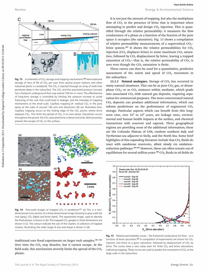
Fig. 13 A schematic of CO2 storage and trapping mechanisms.480 Here extensivestorage of tens of Mt of CO2 per year from several power stations and otherindustrial plants is considered. The CO2 is injected through an array of wells thatpenetrate deep in the subsurface. The CO2 and the associated pressure increasehas a footprint underground that may extend 100 km or more. The effectivenessof long-term storage is controlled by limiting the pressure increase to avoidfracturing of the rock that could lead to leakage, and the interplay of trappingmechanisms at the small scale. Capillary trapping (A: residual CO2 in the porespace at the scale of around 100 mm) and dissolution (B) are illustrated here.Capillary trapping occurs at the trailing edge of the CO2 plume, where brinedisplaces CO2. This limits the spread of CO2 in its own phase. Dissolution occursthroughout the plume: the CO2-saturated brine is dense and sinks. Both processesprevent the escape of CO2 to the surface.
Fig. 14 Pore-scale images of trapped CO2 in sandstone.571 (a) This is a two-dimensional cross-section of a three-dimensional image showing in grey scale therock (grey), CO2 (light) and brine (dark). The segmented image, used to identifythe fluid phases, is shown in (b). The trapped CO2 ganglia in three dimensions areshown in (c). The colours indicate the size of the clusters. A collection of trappedclusters, illustrating the wide range of size and shape is shown in (d).
Fig. 15 Relative permeability curves – the fractional conductance for flow – as afunction of brine saturation.482 A compilation of experiments are shown for CO2
injection into brine to a given saturation, followed by displacement of CO2 bybrine. The curves have a zero value even for finite CO2 and brine saturations,indicating trapping. These curves are used to predict the movement of CO2 at thelarge scale in the subsurface.
Review Energy & Environmental Science
Publ
ishe
d on
13
Sept
embe
r 20
13. D
ownl
oade
d by
Im
peri
al C
olle
ge L
ondo
n L
ibra
ry o
n 09
/10/
2013
15:
04:4
4.
View Article Online
traditional core ood experiments on larger rock samples.481–483
Over time the CO2 may dissolve, but it cannot escape. At theeld scale, this mechanism severely limits the spread of the CO2
plume.
This journal is ª The Royal Society of Chemistry 2013
It is not just the amount of trapping, but also the multiphaseow of CO2 in the presence of brine that is important whenattempting to predict and design CO2 injection. This is quan-tied through the relative permeability: it measures the owconductance of a phase as a function of the fraction of the porespace it occupies (the saturation). Fig. 15 shows a compilationof relative permeability measurements of a supercritical CO2–
brine system.482 It shows the relative permeabilities for CO2
injection (CO2 displaces brine) to some maximum CO2 satura-tion, followed by CO2 displacement by brine, leaving a trappedsaturation of CO2—that is, the relative permeability of CO2 iszero even though the CO2 saturation is nite.
These curves can then be used for a quantitative, predictiveassessment of the extent and speed of CO2 movement inthe subsurface.
12.1.2 Natural analogues. Storage of CO2 has occurred inmany natural situations. This can be as pure CO2 gas, or dense-phase CO2; or as CO2 mixtures within methane, which gradeinto associated CO2 with natural gas deposits, requiring sepa-ration for commercial purposes. Themore concentrated naturalCO2 deposits can produce additional information, which caninform predictions on the performance of engineered CO2
storage. Particular aspects which can benet from this long-term view, over 104 to 106 years, are leakage rates, environ-mental and human health impacts at the surface, and chemicalinteractions with reservoir and caprock. Three geographicalregions are providing most of the additional information; theseare the Colorado Plateau of USA, onshore southern Italy andTyrrhenian sea adjacent to Sicily, and the North Sea. Some briefhighlights of this expanding literature include that CO2 uids doreact with sandstone reservoirs, albeit slowly via oxidation–reduction pathways.484,485 However, these can oen remain out ofequilibrium for several million years.486 CO2 uids in oil elds do
Energy Environ. Sci.
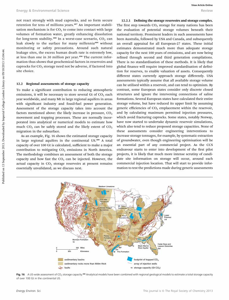
Energy & Environmental Science Review
Publ
ishe
d on
13
Sept
embe
r 20
13. D
ownl
oade
d by
Im
peri
al C
olle
ge L
ondo
n L
ibra
ry o
n 09
/10/
2013
15:
04:4
4.
View Article Online
not react strongly with mud caprocks, and so form secureretention for tens of millions years.487 An important stabili-sation mechanism is for CO2 to come into contact with largevolumes of formation water, greatly enhancing dissolutionfor long-term stability.488 In a worst-case scenario, CO2 canleak slowly to the surface for many millennia489 withoutmonitoring or safety precautions. Around such naturalleakage sites, the excess human death rate is extremely low,at less than one in 30 million per year.490 The current infor-mation thus shows that geochemical factors in reservoirs andcaprocks for CO2 storage need not be adverse, if factored intosite choice.
12.2 Regional assessments of storage capacity
To make a signicant contribution to reducing atmosphericemissions, it will be necessary to store several Gt of CO2 eachyear worldwide, and many Mt in large regional aquifers in areaswith signicant industry and fossil-fuel power generation.Assessment of the storage capacity takes into account thefactors mentioned above: the likely increase in pressure, CO2
movement and trapping processes. These are normally incor-porated into analytical or numerical models to estimate howmuch CO2 can be safely stored and the likely extent of CO2
migration in the subsurface.As an example, Fig. 16 shows the estimated storage capacity
in large regional aquifers in the continental US.480 A totalcapacity of over 100 Gt is calculated, sufficient to make a majorcontribution to mitigating CO2 emissions in North America.The methodology combines an assessment of both the storagecapacity and how fast the CO2 can be injected. However, theactual capacity in CO2 storage reservoirs at present remainsessentially unvalidated, as we discuss next.
Fig. 16 A US-wide assessment of CO2 storage capacity.480 Analytical models have beof over 100 Gt in the continental US.
Energy Environ. Sci.
12.2.1 Dening the storage reservoirs and storage complex.The rst step towards CO2 storage for many nations has beenthe evaluation of potential storage volumes beneath theirnational territory. Prominent leaders in such assessments havebeen Australia, followed by USA and Canada, and subsequentlyan overall appraisal for all European-27 states. These initialestimates demonstrated much more than adequate storagecapacity for the next 100 years of emissions, and are now beingrened through second and third generation compilations.There is no standardisation of these methods. It is likely thatglobal nance will require improved standardisation of deni-tion for reserves, to enable valuation of assets. Consequentlydifferent states currently approach storage differently. USAassessments typically assume that all available storage volumecan be utilised within a reservoir, and can tend to optimism. Bycontrast, some European states consider only discrete closedstructures and ignore the intervening connections of salineformations. Several European states have calculated their entirestorage volume, but have reduced its upper limit by assuminggeneric efficiencies of CO2 emplacement within the reservoir,and by calculating maximum permitted injection pressures,which avoid fracturing caprocks. Some states, notably Norway,have now started to undertake dynamic reservoir simulations,which also tend to reduce proposed storage capacities. None ofthese assessments consider engineering interventions toincrease storage tonnages, for example, by systematic extractionof groundwater, even though engineering optimisation will bean essential part of any commercial project. As the CCSendeavour starts to enter into development of the rst pilotprojects, it is likely that much more intense scrutiny of candi-date site information on storage will occur, around eachcommercial injection location. That will start to provide infor-mation to test the predictions made during generic assessments
en combined with regional geological models to estimate a total storage capacity
This journal is ª The Royal Society of Chemistry 2013
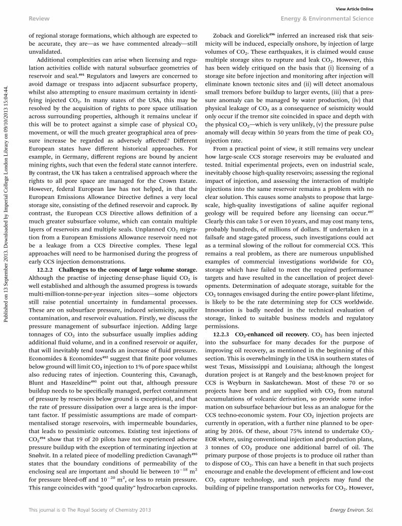
Review Energy & Environmental Science
Publ
ishe
d on
13
Sept
embe
r 20
13. D
ownl
oade
d by
Im
peri
al C
olle
ge L
ondo
n L
ibra
ry o
n 09
/10/
2013
15:
04:4
4.
View Article Online
of regional storage formations, which although are expected tobe accurate, they are—as we have commented already—stillunvalidated.
Additional complexities can arise when licensing and regu-lation activities collide with natural subsurface geometries ofreservoir and seal.491 Regulators and lawyers are concerned toavoid damage or trespass into adjacent subsurface property,whilst also attempting to ensure maximum certainty in identi-fying injected CO2. In many states of the USA, this may beresolved by the acquisition of rights to pore space utilisationacross surrounding properties, although it remains unclear ifthis will be to protect against a simple case of physical CO2
movement, or will the much greater geographical area of pres-sure increase be regarded as adversely affected? DifferentEuropean states have different historical approaches. Forexample, in Germany, different regions are bound by ancientmining rights, such that even the federal state cannot interfere.By contrast, the UK has taken a centralised approach where therights to all pore space are managed for the Crown Estate.However, federal European law has not helped, in that theEuropean Emissions Allowance Directive denes a very localstorage site, consisting of the dened reservoir and caprock. Bycontrast, the European CCS Directive allows denition of amuch greater subsurface volume, which can contain multiplelayers of reservoirs and multiple seals. Unplanned CO2 migra-tion from a European Emissions Allowance reservoir need notbe a leakage from a CCS Directive complex. These legalapproaches will need to be harmonised during the progress ofearly CCS injection demonstrations.
12.2.2 Challenges to the concept of large volume storage.Although the practise of injecting dense-phase liquid CO2 iswell established and although the assumed progress is towardsmulti-million-tonne-per-year injection sites—some objectorsstill raise potential uncertainty in fundamental processes.These are on subsurface pressure, induced seismicity, aquifercontamination, and reservoir evaluation. Firstly, we discuss thepressure management of subsurface injection. Adding largetonnages of CO2 into the subsurface usually implies addingadditional uid volume, and in a conned reservoir or aquifer,that will inevitably tend towards an increase of uid pressure.Economides & Economides492 suggest that nite poor volumesbelow ground will limit CO2 injection to 1% of pore space whilstalso reducing rates of injection. Countering this, Cavanagh,Blunt and Haszeldine493 point out that, although pressurebuildup needs to be specically managed, perfect containmentof pressure by reservoirs below ground is exceptional, and thatthe rate of pressure dissipation over a large area is the impor-tant factor. If pessimistic assumptions are made of compart-mentalised storage reservoirs, with impermeable boundaries,that leads to pessimistic outcomes. Existing test injections ofCO2
494 show that 19 of 20 pilots have not experienced adversepressure buildup with the exception of terminating injection atSnøhvit. In a related piece of modelling prediction Cavanagh495
states that the boundary conditions of permeability of theenclosing seal are important and should lie between 10�18 m2
for pressure bleed-off and 10�20 m2, or less to retain pressure.This range coincides with “good quality” hydrocarbon caprocks.
This journal is ª The Royal Society of Chemistry 2013
Zoback and Gorelick496 inferred an increased risk that seis-micity will be induced, especially onshore, by injection of largevolumes of CO2. These earthquakes, it is claimed would causemultiple storage sites to rupture and leak CO2. However, thishas been widely critiqued on the basis that (i) licensing of astorage site before injection and monitoring aer injection willeliminate known tectonic sites and (ii) will detect anomaloussmall tremors before buildup to larger events, (iii) that a pres-sure anomaly can be managed by water production, (iv) thatphysical leakage of CO2 as a consequence of seismicity wouldonly occur if the tremor site coincided in space and depth withthe physical CO2—which is very unlikely, (v) the pressure pulseanomaly will decay within 50 years from the time of peak CO2
injection rate.From a practical point of view, it still remains very unclear
how large-scale CCS storage reservoirs may be evaluated andtested. Initial experimental projects, even on industrial scale,inevitably choose high-quality reservoirs; assessing the regionalimpact of injection, and assessing the interaction of multipleinjections into the same reservoir remains a problem with noclear solution. This causes some analysts to propose that large-scale, high-quality investigations of saline aquifer regionalgeology will be required before any licensing can occur.497
Clearly this can take 5 or even 10 years, and may cost many tens,probably hundreds, of millions of dollars. If undertaken in afailsafe and stage-gated process, such investigations could actas a terminal slowing of the rollout for commercial CCS. Thisremains a real problem, as there are numerous unpublishedexamples of commercial investigations worldwide for CO2
storage which have failed to meet the required performancetargets and have resulted in the cancellation of project devel-opments. Determination of adequate storage, suitable for theCO2 tonnages envisaged during the entire power-plant lifetime,is likely to be the rate determining step for CCS worldwide.Innovation is badly needed in the technical evaluation ofstorage, linked to suitable business models and regulatorypermissions.
12.2.3 CO2-enhanced oil recovery. CO2 has been injectedinto the subsurface for many decades for the purpose ofimproving oil recovery, as mentioned in the beginning of thissection. This is overwhelmingly in the USA in southern states ofwest Texas, Mississippi and Louisiana; although the longestduration project is at Rangely and the best-known project forCCS is Weyburn in Saskatchewan. Most of these 70 or soprojects have been and are supplied with CO2 from naturalaccumulations of volcanic derivation, so provide some infor-mation on subsurface behaviour but less as an analogue for theCCS techno-economic system. Four CO2 injection projects arecurrently in operation, with a further nine planned to be oper-ating by 2016. Of these, about 75% intend to undertake CO2-EOR where, using conventional injection and production plans,3 tonnes of CO2 produce one additional barrel of oil. Theprimary purpose of those projects is to produce oil rather thanto dispose of CO2. This can have a benet in that such projectsencourage and enable the development of efficient and low-costCO2 capture technology, and such projects may fund thebuilding of pipeline transportation networks for CO2. However,
Energy Environ. Sci.
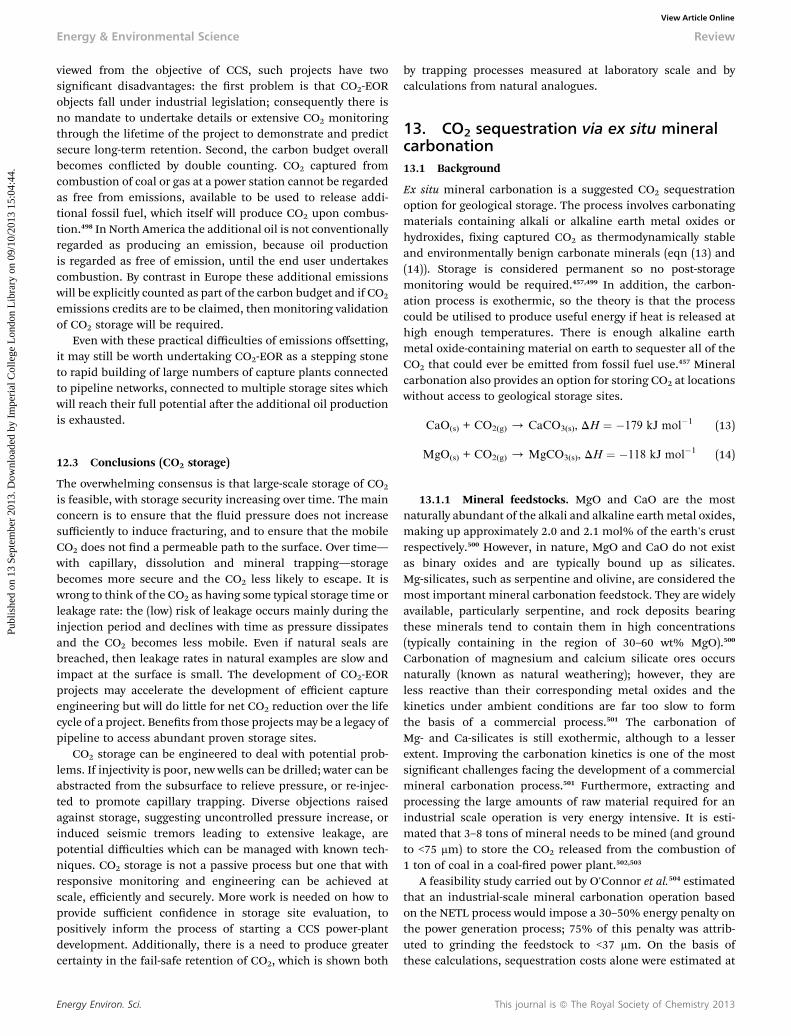
Energy & Environmental Science Review
Publ
ishe
d on
13
Sept
embe
r 20
13. D
ownl
oade
d by
Im
peri
al C
olle
ge L
ondo
n L
ibra
ry o
n 09
/10/
2013
15:
04:4
4.
View Article Online
viewed from the objective of CCS, such projects have twosignicant disadvantages: the rst problem is that CO2-EORobjects fall under industrial legislation; consequently there isno mandate to undertake details or extensive CO2 monitoringthrough the lifetime of the project to demonstrate and predictsecure long-term retention. Second, the carbon budget overallbecomes conicted by double counting. CO2 captured fromcombustion of coal or gas at a power station cannot be regardedas free from emissions, available to be used to release addi-tional fossil fuel, which itself will produce CO2 upon combus-tion.498 In North America the additional oil is not conventionallyregarded as producing an emission, because oil productionis regarded as free of emission, until the end user undertakescombustion. By contrast in Europe these additional emissionswill be explicitly counted as part of the carbon budget and if CO2
emissions credits are to be claimed, then monitoring validationof CO2 storage will be required.
Even with these practical difficulties of emissions offsetting,it may still be worth undertaking CO2-EOR as a stepping stoneto rapid building of large numbers of capture plants connectedto pipeline networks, connected to multiple storage sites whichwill reach their full potential aer the additional oil productionis exhausted.
12.3 Conclusions (CO2 storage)
The overwhelming consensus is that large-scale storage of CO2
is feasible, with storage security increasing over time. The mainconcern is to ensure that the uid pressure does not increasesufficiently to induce fracturing, and to ensure that the mobileCO2 does not nd a permeable path to the surface. Over time—with capillary, dissolution and mineral trapping—storagebecomes more secure and the CO2 less likely to escape. It iswrong to think of the CO2 as having some typical storage time orleakage rate: the (low) risk of leakage occurs mainly during theinjection period and declines with time as pressure dissipatesand the CO2 becomes less mobile. Even if natural seals arebreached, then leakage rates in natural examples are slow andimpact at the surface is small. The development of CO2-EORprojects may accelerate the development of efficient captureengineering but will do little for net CO2 reduction over the lifecycle of a project. Benets from those projects may be a legacy ofpipeline to access abundant proven storage sites.
CO2 storage can be engineered to deal with potential prob-lems. If injectivity is poor, new wells can be drilled; water can beabstracted from the subsurface to relieve pressure, or re-injec-ted to promote capillary trapping. Diverse objections raisedagainst storage, suggesting uncontrolled pressure increase, orinduced seismic tremors leading to extensive leakage, arepotential difficulties which can be managed with known tech-niques. CO2 storage is not a passive process but one that withresponsive monitoring and engineering can be achieved atscale, efficiently and securely. More work is needed on how toprovide sufficient condence in storage site evaluation, topositively inform the process of starting a CCS power-plantdevelopment. Additionally, there is a need to produce greatercertainty in the fail-safe retention of CO2, which is shown both
Energy Environ. Sci.
by trapping processes measured at laboratory scale and bycalculations from natural analogues.
13. CO2 sequestration via ex situ mineralcarbonation13.1 Background
Ex situ mineral carbonation is a suggested CO2 sequestrationoption for geological storage. The process involves carbonatingmaterials containing alkali or alkaline earth metal oxides orhydroxides, xing captured CO2 as thermodynamically stableand environmentally benign carbonate minerals (eqn (13) and(14)). Storage is considered permanent so no post-storagemonitoring would be required.457,499 In addition, the carbon-ation process is exothermic, so the theory is that the processcould be utilised to produce useful energy if heat is released athigh enough temperatures. There is enough alkaline earthmetal oxide-containing material on earth to sequester all of theCO2 that could ever be emitted from fossil fuel use.457 Mineralcarbonation also provides an option for storing CO2 at locationswithout access to geological storage sites.
CaO(s) + CO2(g) / CaCO3(s), DH ¼ �179 kJ mol�1 (13)
MgO(s) + CO2(g) / MgCO3(s), DH ¼ �118 kJ mol�1 (14)
13.1.1 Mineral feedstocks. MgO and CaO are the mostnaturally abundant of the alkali and alkaline earthmetal oxides,making up approximately 2.0 and 2.1 mol% of the earth's crustrespectively.500 However, in nature, MgO and CaO do not existas binary oxides and are typically bound up as silicates.Mg-silicates, such as serpentine and olivine, are considered themost important mineral carbonation feedstock. They are widelyavailable, particularly serpentine, and rock deposits bearingthese minerals tend to contain them in high concentrations(typically containing in the region of 30–60 wt% MgO).500
Carbonation of magnesium and calcium silicate ores occursnaturally (known as natural weathering); however, they areless reactive than their corresponding metal oxides and thekinetics under ambient conditions are far too slow to formthe basis of a commercial process.501 The carbonation ofMg- and Ca-silicates is still exothermic, although to a lesserextent. Improving the carbonation kinetics is one of the mostsignicant challenges facing the development of a commercialmineral carbonation process.501 Furthermore, extracting andprocessing the large amounts of raw material required for anindustrial scale operation is very energy intensive. It is esti-mated that 3–8 tons of mineral needs to be mined (and groundto <75 mm) to store the CO2 released from the combustion of1 ton of coal in a coal-red power plant.502,503
A feasibility study carried out by O'Connor et al.504 estimatedthat an industrial-scale mineral carbonation operation basedon the NETL process would impose a 30–50% energy penalty onthe power generation process; 75% of this penalty was attrib-uted to grinding the feedstock to <37 mm. On the basis ofthese calculations, sequestration costs alone were estimated at
This journal is ª The Royal Society of Chemistry 2013
Review Energy & Environmental Science
Publ
ishe
d on
13
Sept
embe
r 20
13. D
ownl
oade
d by
Im
peri
al C
olle
ge L
ondo
n L
ibra
ry o
n 09
/10/
2013
15:
04:4
4.
View Article Online
50–100 US$ tCO2�1, an order of magnitude higher than the
current cost of geological storage at 5–10 US$ tCO2�1.437
O'Connor's costings are still used as the official best-casescenario estimated costs for mineral carbonation by many ofthe important organisations and agencies advising on climatechange and mitigation strategies, such as the IEA andIPCC.437,457
13.1.2 Indirect mineral carbonation. Over the last fewyears, there has been a growing interest in developing indirectaqueous carbonation processes where metal extraction andcarbonate precipitation is carried out in two or more stages.Whilst indirect processes are more complex, conditions can beoptimised for each stage individually. Furthermore, indirectprocesses oen generate separate streams of the differentreaction products (typically magnesium or calcium carbonate,silica, and iron oxides), which are of commercial value whenobtained at sufficient purities. A comprehensive analysis ofpotential applications for mineral carbonation products isprovided by Sanna et al.505 The sale of suchmaterials might helpto subsidise process costs, particularly if the technology reachesthe demonstration or early-stage industrial deployment phase.However, wide-scale deployment would saturate any potentialhigh value market, and low-value applications will not support asignicant market.505
13.1.3 Carbonation of alkali waste streams. Alkali andalkaline earth metal-rich waste streams such as iron and steelslags, ash from fossil fuel combustion, waste concrete andcement kiln dust offer a number of advantages as feedstocks forCO2 mineralisation applications. They are cheap and widelyavailable; they tend to be much more reactive than naturallyoccurring Mg and Ca-silicates; and in most cases, they requireminimal preparation. Furthermore, their use helps to addressissues and costs associated with waste disposal, particularly ifthe process generates marketable by-products. In someinstances, mineral carbonation may also serve as a means fortreating environmentally hazardous waste streams. Forexample, mineral carbonation reduces the mobility of heavymetal trace elements such as Pb, Cd and Ni found in somewastes, which can leach into the surrounding environment aerdisposal.506 CO2 mineralisation can also be used to neutralisehighly caustic waste streams such as red mud produced frombauxite processing for aluminium production.507
Pilot-scale testing of this technology is likely to follow in thenear future.508 However, like y ash and indeed most otherpotential waste-derived feedstocks, the CO2 storage potential ofiron and steel slags is low—estimated at up to 170 MtCO2 peryear509 compared with total global CO2 emissions from the ironand steel sector of 2.3 Gt per year.510
13.1.4 Future scope. Further development of ex situ CO2
mineralisation processes that utilise waste feedstocks (orwollastonite) and generate valuable by-products may help toprogress technologies to the pilot and demonstrationphases. Furthermore, it is likely that CO2 mineralisation ofwaste streams will nd niche applications for hazardous wasteremediation and as a means for some industries to producevaluable by-products from their waste whilst reducing their CO2
emissions. However, if CO2 mineralisation technologies are to
This journal is ª The Royal Society of Chemistry 2013
offer the kind of CO2 storage capacities required for climatechange mitigation applications, economically feasible processesutilising naturally occurring Mg- and Ca-silicates must bedeveloped; and the energy required to grind materials tothe required size distribution, together with the low value of theproduced material will make this an exceptionally challengingproposition.
14. Carbon dioxide re-use14.1 Background
Carbon dioxide re-use (CDR) is a purported alternative tostorage that involves the production of saleable products fromcaptured CO2. CDR includes the use of CO2 as a technologicaluid and as a reagent for the production of chemicals (CO2-to-chemicals), plastics (CO2-to-plastics), or fuels (CO2-to-fuels).The combined system of CO2 capture with CO2 re-use is typicallyreferred to as carbon capture and utilisation (CCU). In a fewcases, CDR can result in some permanent storage and removalof CO2 from the carbon cycle (e.g. enhanced oil recovery ormineral carbonisation); however, in most cases, CDR will resultin re-emission further down the line (e.g. the use of CO2 as atechnological uid or as a precursor for fuel production). In thelatter case, the lifetime in which CO2 is removed from thecarbon cycle will vary: some uses, such as the use of CO2 as afuel precursor, are very short term (days to months); whilstothers, such as its use as a precursor for plastics, have a longerterm. In fact, the use of CO2 as a precursor for some plastics mayresult in the CO2 being xed away from the atmosphere fordecades and can, therefore, be considered a form of storage.
The primary advantage of CDR compared with CCS is that itsend product is of value. It has been argued that increaseddeployment of CDR processes will therefore drive up the marketprice of CO2, incentivising development and deployment of CO2
capture technologies. CCS on the other hand requires marketintervention by governments through the application of strictpenalties or economic support and subsidies to achieve thesame result. However, the argument that CDR will meaningfullyincrease the price of CO2 fails to take into account the vastsupply of CO2 and the comparatively small demand for CO2.
14.2 Current status of CDR technology
Despite the fact that CO2 is a renewable, widely available, low-cost and low-toxicity C1 feedstock, current industrial demand isrelatively low, amounting to around 232 Mt per year, with only afew commercial processes currently using CO2 as a raw material(Table 8). Most of the current demand is met by naturallyderived CO2 with only 40 Mt obtained from anthropogenicsources of which 70% is used for EOR purposes and anothersignicant fraction used for urea production.511 At present, themarket for CO2 is several orders of magnitude smaller than theamount of CO2 released into the atmosphere each year fromanthropogenic sources and approximately 60 times smallerthan the amount of CO2 emitted from large point sources(�14 000 Mt per year).512 The following sections provide a briefoverview of the current status of CDR technology.
Energy Environ. Sci.
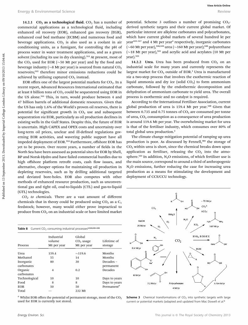
Energy & Environmental Science Review
Publ
ishe
d on
13
Sept
embe
r 20
13. D
ownl
oade
d by
Im
peri
al C
olle
ge L
ondo
n L
ibra
ry o
n 09
/10/
2013
15:
04:4
4.
View Article Online
14.2.1 CO2 as a technological uid. CO2 has a number ofcommercial applications as a technological uid, includingenhanced oil recovery (EOR), enhanced gas recovery (EGR),enhanced coal bed methane (ECBM) and numerous food andbeverage applications. CO2 is also used as a coolant in airconditioning units, as a fumigant, for controlling the pH ofprocess water in water treatment applications, and as a greensolvent (including its use in dry cleaning).513 At present, most ofthe CO2 used for EOR (�50 Mt per year) and by the food andbeverage industry (�8 Mt per year) is sourced from natural CO2
reservoirs;512 therefore minor emissions reductions could beachieved by utilising captured CO2 instead.
EOR offers one of the largest potential markets for CO2. In arecent report, Advanced Resources International estimated thatat least 8 billion tons of CO2 could be sequestered using EOR inthe US alone.511 This, in turn, would produce between 4 and47 billion barrels of additional domestic resources. Given thatthe US has only 1.6% of the World's proven oil reserves, there ispotential for signicant growth in CO2 use and subsequentsequestration via EOR, particularly as oil production declines inexisting wells in the Gulf States. Despite this, the future of EORis uncertain. High CAPEX and OPEX costs and uncertainty overlong-term oil prices, unclear and ill-dened regulations gov-erning EOR activities, and wavering public support have allimpeded deployment of EOR.514 Furthermore, offshore EOR hasyet to be proven. Over recent years, a number of elds in theNorth Sea have been assessed as potential sites for EOR by Shell,BP and Norsk-Hydro and have failed commercial hurdles due tohigh offshore platform retrot costs, cash ow issues, andalternative, cheaper options for maintaining oil production indepleting reservoirs, such as by drilling additional targetedand deviated bore-holes. EOR also competes with othermethods of enhanced resource production, such as unconven-tional gas and tight oil, coal-to-liquids (CTL) and gas-to-liquid(GTL) technologies.
CO2 to chemicals. There are a vast amount of differentchemicals that in theory could be produced using CO2 as a C1
feedstock; however, many would either prove impractical toproduce from CO2 on an industrial scale or have limited market
Table 8 Current CO2 consuming industrial processes3,520,636–638
Process
IndustrialvolumeMt per year
GlobalCO2 usageMt per year
Lifetime ofstorage
Urea 159.4 �119.6 MonthsMethanol 55 14 MonthsInorganiccarbonates
80 30 Decades –permanent
Organiccarbonates
4 0.2 Decades
Technological 10 10 Days to yearsFood 8 8 Days to yearsEOR 50 50 Permanenta
Total — 232 Mt
a Whilst EOR offers the potential of permanent storage, most of the CO2used for EOR is currently not stored.
Energy Environ. Sci.
potential. Scheme 3 outlines a number of promising CO2-derived synthetic targets and their current global market. Ofparticular interest are alkylene carbonates and polycarbonates,which have current global markets of several hundred kt peryear515–517 and 4 Mt per year3 respectively, inorganic carbonates(�60 Mt per year),518,519 urea (�160 Mt per year);520 polyurethane(�18 Mt per year),521 and acrylic acid and acrylates (10 Mt peryear).522
14.2.2 Urea. Urea has been produced from CO2 on anindustrial scale for many years and currently represents thelargest market for CO2 outside of EOR.3 Urea is manufacturedvia a two-step process that involves the exothermic reaction ofliquid ammonia and dry ice (solid CO2) to form ammoniumcarbonate, followed by the endothermic decomposition anddehydration of ammonium carbonate to yield urea. The overallprocess is exothermic and no catalyst is required.
According to the International Fertiliser Association, currentglobal production of urea is 159.4 Mt per year.520 Given thatbetween 0.735 and 0.75 tonnes of CO2 are consumed per tonneof urea, CO2 consumption as a consequence of urea productionis around 119.6 Mt per year. The overwhelming market for ureais that of the fertiliser industry, which consumes over 80% oftotal global urea production.3
The climate change mitigation potential of ramping up ureaproduction is poor. As discussed by Fennell,503 the storage ofCO2 within urea is short, since the chemical breaks down uponapplication as fertiliser, releasing the CO2 into the atmo-sphere.523 In addition, N2O emissions, of which fertiliser use isthe main source, correspond to around a third of anthropogenicN2O emissions, further reducing the case for increasing ureaproduction as a means for stimulating the development anddeployment of CCS/CCU technology.
Scheme 3 Chemical transformations of CO2 into synthetic targets with largecurrent or potential markets (adapted and updated from Mac Dowell et al.3
This journal is ª The Royal Society of Chemistry 2013
Review Energy & Environmental Science
Publ
ishe
d on
13
Sept
embe
r 20
13. D
ownl
oade
d by
Im
peri
al C
olle
ge L
ondo
n L
ibra
ry o
n 09
/10/
2013
15:
04:4
4.
View Article Online
14.3 CO2-to-fuels
The production of fuels from CO2 is ostensibly an attractivegoal, given that the global fuels market is roughly two orders ofmagnitude greater than that of chemicals. In order for theproduction and use of CO2-derived fuels to contribute to climatechange mitigation efforts, the energy requirements mustbe supplied from non-fossil sources, i.e. RETs or nuclear. The ideais that the application of such technology may provide a way ofstoring excess electrical or intermittent electricity production. Thefuels produced could be used to re a power plant, generator orfuel cell during periods when RETs relying on intermittent energysources (such as the sun or wind) are not able to meet demand;alternatively, the fuels could be used for mobile or distributedapplications. Furthermore, the production of easy to transportfuels from CO2, utilising renewable energy at a remote location(such as geothermal or solar) might prove a more convenient andcost-effective way of delivering otherwise stranded resources tomarket than constructing transmission lines or nding otherpotential uses for such resources.
CO2 is the lowest energy state of any binary neutral carbonspecies and the ultimate product of energy-releasing hydro-carbon combustion and metabolic pathways. Therefore, asignicant energy input is required to overcome the substantialthermodynamic and kinetic barriers of converting CO2 into auseable fuel. When considering the energetics of CO2 activa-tion, only a very few synthetic fuel targets can possibly beconsidered viable, these targets include syngas, methane,methanol and formic acid.3
Methanol can be produced via the catalytic hydrogenation ofCO2 utilising similar conditions catalysts to those used for theproduction of methanol in the conventional commercialapproach.524 In this case, the use of hydrocarbons can be avoi-ded by using H2 from renewable sources, i.e. water splitting viaelectrolysis. However, the drawbacks with this approach are thatequilibrium yields are much lower compared with methanolproduction from syngas. In addition, a third of the hydrogen isconverted to water; this process is inefficient, particularly whenconsidering that H2 production via electrolysis of water is a veryenergy intensive process. Furthermore, both methods ofproducing methanol consume a great deal of thermal energy,and the lifecycle efficiency, particularly considering that theoriginal source of energy for the production of H2 is electricity,is exceptionally low. It has been argued503 that pumped storageof the electricity, combined with the use of electric vehicles isaround ve times more efficient in terms of miles driven thanusing the electricity to produce hydrogen, then methanol, thenusing this to run an internal combustion engine.
14.4 Future outlook
At present, utilisation of CO2, particularly CO2 from anthropo-genic sources, is low. The use of anthropogenic CO2 in place ofCO2 derived from natural deposits will offer small emissionsreductions, although in the context of climate change mitiga-tion, the impact will be insignicant. In the short term,increased deployment of EOR has the potential to offer thelargest economic stimulus for large point sources to capture
This journal is ª The Royal Society of Chemistry 2013
and subsequently store their CO2. However, a clear frameworkfor regulating and incentivising wide-scale deployment of CCSand EOR that also addresses potential liability issues associatedwith EOR coupled with permanent storage needs to be estab-lished. Further work is also required to assess the feasibility andany potential deployment issues associated with EOR andpermanent storage particularly at off-shore locations.
CO2-to-fuels technology is far from commercial status andwill have to compete with other unconventional methods ofproducing liquid fuels, such as GTL and CTL in addition toother means of storing and utilising energy such as high effi-ciency batteries and ultracapacitors. The future of CO2-to-fuelstechnology, therefore, remains highly uncertain because of theinherent thermodynamic efficiency penalties.
15. Policy design and implications forinvestment15.1 Introduction
The preceding sections of this paper have discussed the range ofCCS technologies under development. Whilst it is perhaps tooearly to say which set of technologies will come to dominate theeld, it is certainly the case that any CCS technology will requirepolicy support to ensure deployment at the scale and volumerequired to deliver on climate change goals.525 This sectionreviews the recent history of policy support for CCS, focusingon the power generation sector in the UK and EU, and discussesthe continuing policy challenges which are faced, together withthe implications for potential investment in CCS projects. Thefocus reects the key role that decarbonisation of the electricitygeneration sector is expected to have in meeting CO2 emissionsreduction goals, the ‘leading role’ that the UK is taking with apackage of measures intended to support CCS projects both in,and beyond, the demonstration phase, together with the EU-wide policies to support demonstration projects.526
It is not the purpose of this section to review estimatedcostings for different technologies, since this subject is highlycontestable and frequently quite subjective. A recent review ofcosts in industrial settings deals with this subject527 and anexcellent summary of recent pilot and large-scale costing data isavailable from the Global Carbon Capture and Storage Instituteon a yearly basis.528
16. A recent history of UK and EU CCSpolicy
In 2007, the UK Government launched a competition fordemonstrating post-combustion capture on a coal-red powerstation, to be operational by 2014, aiming to ‘make the UK aworld leader in this globally important technology’.529,530 Two ofthe applicants for the competition were awarded funding forFront End Engineering and Design (FEED) work. The 2010Spending Review conrmed that Government would provide upto £1 billion for the successful project, but on the same day asthis announcement was made, one of the remaining applicantswithdrew from the competition on the grounds that theeconomic conditions were not right, leaving only one remaining
Energy Environ. Sci.
Energy & Environmental Science Review
Publ
ishe
d on
13
Sept
embe
r 20
13. D
ownl
oade
d by
Im
peri
al C
olle
ge L
ondo
n L
ibra
ry o
n 09
/10/
2013
15:
04:4
4.
View Article Online
applicant—a post-combustion retrot to part of ScottishPower'sLongannet coal-red plant. During the same year, the UKGovernment reaffirmed its commitment to a further three CCSdemonstration projects, and completed a market soundingexercise to ‘help the department to explore workable options forthe CCS demonstration project selection and fundingprocesses, and learn about projects being considered byindustry’.531 A key development was the decision to make gasred generation eligible for the competition, following recom-mendations by the Committee on Climate Change.532
It was originally intended that funding for the further threeprojects would be nanced by a levy on consumer bills, but thislevy was later shelved. Longer term, the CCS funding mecha-nism is bound up in the Electricity Market Reform (EMR)process.533 At the EU level, it was anticipated that the NewEntrant Reserve funding (commonly referred to as the NER 300)would be available from the auctioning of 300 million EU ETSallowances, at the time expected to raise betweenV4.5 andV9.0billion in total with a substantial fraction of this to be availablefor CCS projects across the EU. To be eligible, all prospectiveNER 300 projects are required to secure 50% co-funding fromother sources.534
In December 2010, the UK Government launched a consul-tation on the EMR which set out a proposed package of policiesto ‘ensure that low-carbon technologies become a more attrac-tive choice for investors, and adequately reward back upcapacity to ensure the lights stay on’. These reforms were drivenby Government's belief that ‘the current market will not deliveron the Government's objectives for decarbonisation, security ofsupply or affordability for consumers’.535 The four key EMRmechanisms are:
(1) A Feed-in Tariff (FiT) to stabilise and top-up the revenuesof low-carbon generators including CCS, transferring electricityprice risk from generators to consumers, through a Contract forDifference (CfD).
(2) A carbon price oor to reduce uncertainty for investorsand incentivise low-carbon generation by topping up the EUETS carbon price.
(3) An Emissions Performance Standard (EPS) to put anannual limit on the amount of CO2 that a plant can emit,equivalent to 450 gCO2 kW h�1 for plant operating at baseload,thereby effectively prohibiting new unabated coal-red plantbut new allowing new unabated CCGT plant.
(4) A capacity mechanism to ensure that there is sufficientgenerating capacity to meet peak demand.
The EMR consultation process was followed by a WhitePaper during 2011536 and in 2012 by a dra Energy Bill537 whichset out the legislative framework for the proposals. In themeantime, however, ScottishPower pulled out of the rstdemonstration plant competition in October 2011, with the UKGovernment citing increased costs and the inability to reach acommercial agreement as the reasons. At the same time, it wasconrmed that the £1 billion of public funds set aside for therst demonstration would be ‘available for a new process’.538
This new process was launched as a ‘CommercialisationProgramme’ and involves a competition through whichsuccessful applicants will receive direct funding from the £1
Energy Environ. Sci.
billion budget and also the possibility of further revenue-basedsupport under the CfD FiT mechanism proposed in the EMR.Applicants for funding from the new process must be able todemonstrate at commercial scale and be operational by 2016–2020.539 The separate process by which the EC selected projectsfor funding under the NER 300 scheme continues in parallelto the UK Government's Commercialisation Programme.However, under the rst round of the NER 300, no CCS projectswere granted funding, though funding is still potentially avail-able in the second round. The level of funding available throughthe NER 300 process will be considerably less than was origi-nally hoped because the market price of EU ETS allowances iswell below the level envisaged when the process was set up. TheEC currently anticipate that the total level of funding from theprocess will be between V1.3 billion and V1.5 billion, withfunding for any individual project capped at 15% of the total,meaning a maximum of V292–337 million for any one project.
At the time of writing (May 2013), the UK Government hasannounced the two preferred bidders for the Commercialisa-tion Programme competition. These are the White Rose project,an oxyfuel-based project based at Drax, North Yorkshire andproposed by a consortium of companies including Alstom, Draxand BOC, working closely with National Grid and who togetherform “Capture Power”;540 and the Peterhead project in Aber-deenshire, Scotland, involving Shell and SSE. Both projects arecurrently performing front-end engineering design studies.Table 9 details projects which were shortlisted for funding byboth the EU and UK CCS competitions.
16.1 Implications for investment in CCS
The generic investment challenges faced by renewable energyand nuclear power plants operating in liberalised energymarkets are well understood. The combination of high capitalcosts and very low operating costs means that such plant aretypically ‘price takers’ because once constructed, it typicallymakes most sense to run them whenever they are physicallyable to do so, almost regardless of electricity prices. It isconventional gas and coal-red plant that have the ‘price maker’role and have the dominant inuence over electricity prices asthey are generally able to remain protable over a wider set ofoperating regimes and pass variations in fuel costs through toconsumers.541 In practice this means that potential investorswill tend to prefer low capital cost conventional gas-red powerstation projects with operating costs linked closely to electricaloutput, even if the lifetime levelised costs of electricity fromhigher capital cost projects are similar.541
CCS introduces another set of challenges because it alsocarries relatively high fuel and operation and maintenancecosts, a carbon cost for the residual CO2 emissions whichcannot be captured, and a potential long-term liabilityassociated with the stored CO2. Whilst the support offeredthrough the FiT mechanism proposed in the EMR suits thecharacteristics of low operating cost plant such as nuclearand wind power, the fuel costs associated with CCS plantssuggest that it may require a premium payment that is linkedto those fuel costs.
This journal is ª The Royal Society of Chemistry 2013
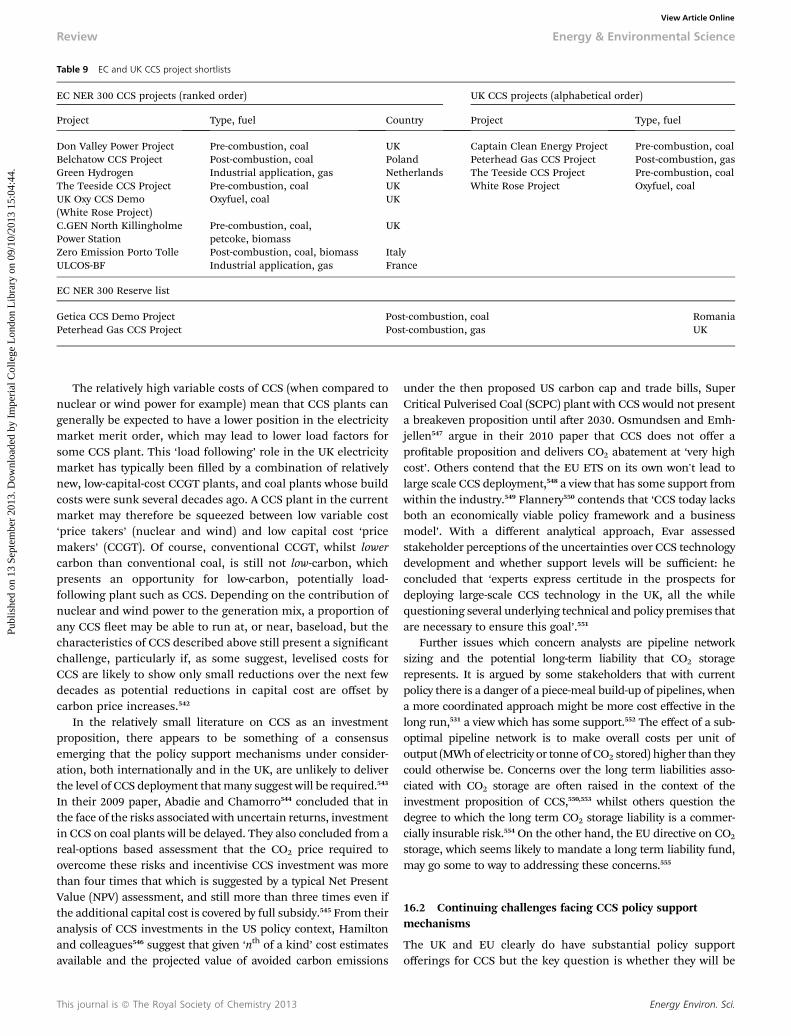
Table 9 EC and UK CCS project shortlists
EC NER 300 CCS projects (ranked order) UK CCS projects (alphabetical order)
Project Type, fuel Country Project Type, fuel
Don Valley Power Project Pre-combustion, coal UK Captain Clean Energy Project Pre-combustion, coalBelchatow CCS Project Post-combustion, coal Poland Peterhead Gas CCS Project Post-combustion, gasGreen Hydrogen Industrial application, gas Netherlands The Teeside CCS Project Pre-combustion, coalThe Teeside CCS Project Pre-combustion, coal UK White Rose Project Oxyfuel, coalUK Oxy CCS Demo(White Rose Project)
Oxyfuel, coal UK
C.GEN North KillingholmePower Station
Pre-combustion, coal,petcoke, biomass
UK
Zero Emission Porto Tolle Post-combustion, coal, biomass ItalyULCOS-BF Industrial application, gas France
EC NER 300 Reserve list
Getica CCS Demo Project Post-combustion, coal RomaniaPeterhead Gas CCS Project Post-combustion, gas UK
Review Energy & Environmental Science
Publ
ishe
d on
13
Sept
embe
r 20
13. D
ownl
oade
d by
Im
peri
al C
olle
ge L
ondo
n L
ibra
ry o
n 09
/10/
2013
15:
04:4
4.
View Article Online
The relatively high variable costs of CCS (when compared tonuclear or wind power for example) mean that CCS plants cangenerally be expected to have a lower position in the electricitymarket merit order, which may lead to lower load factors forsome CCS plant. This ‘load following’ role in the UK electricitymarket has typically been lled by a combination of relativelynew, low-capital-cost CCGT plants, and coal plants whose buildcosts were sunk several decades ago. A CCS plant in the currentmarket may therefore be squeezed between low variable cost‘price takers’ (nuclear and wind) and low capital cost ‘pricemakers’ (CCGT). Of course, conventional CCGT, whilst lowercarbon than conventional coal, is still not low-carbon, whichpresents an opportunity for low-carbon, potentially load-following plant such as CCS. Depending on the contribution ofnuclear and wind power to the generation mix, a proportion ofany CCS eet may be able to run at, or near, baseload, but thecharacteristics of CCS described above still present a signicantchallenge, particularly if, as some suggest, levelised costs forCCS are likely to show only small reductions over the next fewdecades as potential reductions in capital cost are offset bycarbon price increases.542
In the relatively small literature on CCS as an investmentproposition, there appears to be something of a consensusemerging that the policy support mechanisms under consider-ation, both internationally and in the UK, are unlikely to deliverthe level of CCS deployment that many suggest will be required.543
In their 2009 paper, Abadie and Chamorro544 concluded that inthe face of the risks associated with uncertain returns, investmentin CCS on coal plants will be delayed. They also concluded from areal-options based assessment that the CO2 price required toovercome these risks and incentivise CCS investment was morethan four times that which is suggested by a typical Net PresentValue (NPV) assessment, and still more than three times even ifthe additional capital cost is covered by full subsidy.545 From theiranalysis of CCS investments in the US policy context, Hamiltonand colleagues546 suggest that given ‘nth of a kind’ cost estimatesavailable and the projected value of avoided carbon emissions
This journal is ª The Royal Society of Chemistry 2013
under the then proposed US carbon cap and trade bills, SuperCritical Pulverised Coal (SCPC) plant with CCS would not presenta breakeven proposition until aer 2030. Osmundsen and Emh-jellen547 argue in their 2010 paper that CCS does not offer aprotable proposition and delivers CO2 abatement at ‘very highcost’. Others contend that the EU ETS on its own won't lead tolarge scale CCS deployment,548 a view that has some support fromwithin the industry.549 Flannery550 contends that ‘CCS today lacksboth an economically viable policy framework and a businessmodel’. With a different analytical approach, Evar assessedstakeholder perceptions of the uncertainties over CCS technologydevelopment and whether support levels will be sufficient: heconcluded that ‘experts express certitude in the prospects fordeploying large-scale CCS technology in the UK, all the whilequestioning several underlying technical and policy premises thatare necessary to ensure this goal’.551
Further issues which concern analysts are pipeline networksizing and the potential long-term liability that CO2 storagerepresents. It is argued by some stakeholders that with currentpolicy there is a danger of a piece-meal build-up of pipelines, whena more coordinated approach might be more cost effective in thelong run,531 a view which has some support.552 The effect of a sub-optimal pipeline network is to make overall costs per unit ofoutput (MWhof electricity or tonne of CO2 stored) higher than theycould otherwise be. Concerns over the long term liabilities asso-ciated with CO2 storage are oen raised in the context of theinvestment proposition of CCS,550,553 whilst others question thedegree to which the long term CO2 storage liability is a commer-cially insurable risk.554 On the other hand, the EU directive on CO2
storage, which seems likely to mandate a long term liability fund,may go some to way to addressing these concerns.555
16.2 Continuing challenges facing CCS policy supportmechanisms
The UK and EU clearly do have substantial policy supportofferings for CCS but the key question is whether they will be
Energy Environ. Sci.
Energy & Environmental Science Review
Publ
ishe
d on
13
Sept
embe
r 20
13. D
ownl
oade
d by
Im
peri
al C
olle
ge L
ondo
n L
ibra
ry o
n 09
/10/
2013
15:
04:4
4.
View Article Online
sufficient to deliver both the early-stage investment in demon-stration plants and the large-scale CCS deployment that will berequired if the technology is to make a meaningful contributionto meeting climate policy goals. Research undertaken by the UKEnergy Research Centre556–558 suggests that signicant concernsremain and these can summarised as follows:
Technology and construction risk is a particularly importantfactor deterring investment at present. The multiplicity of CCStechnologies, each of which has differing technological char-acteristics, makes this factor especially difficult to tackle. Thehigh up-front capital costs of CCS projects (and the uncertaintyaround those costs), together with delays in the UK demon-stration programme, and the EMR's emphasis on premiumpayments for electricity generated rather than up-front capitalgrants, are exacerbating this risk.
The infrastructural barriers to CCS investment include therst-of-a-kind costs associated with developing a CO2 trans-portation network, and the lack of a systematic policy approachto coordinating and optimising the network through, forexample, pipeline oversizing. There are also more generaluncertainties about the legal liabilities of CO2 storage.
CCS has signicant and variable fuel-related operating costs,which creates a fuel price risk. Although fossil fuel plants aretypically ‘price makers’, with the ability to pass fuel priceincreases on to consumers, there are concerns that the FiT CfDsupport mechanism for UK projects may remove this naturalhedge unless the mechanism is also linked to fuel prices.
CCS has relatively high operating and fuel costs, which maymean that load factor risk could become important by the late2020s. In particular, CCS plant might be required to operateexibly (and therefore at lower load factors) when there isincreased penetration of very-low-marginal-cost nuclear andwind power plants. This has the potential to increase the unitcosts (£/MWh) of CCS generation, thus underminingthe attractiveness of CCS investments unless investors can besure of receiving high prices when plants do run, or canbe compensated in some other way, for example through theproposed capacity payment mechanism. This risk is potentiallygreater for coal CCS than gas CCS, due to the higher capitalintensity of coal plant.
Whilst other low carbon power generation technologies suchas nuclear, wind and solar photovoltaics also generally requiresupport, the unique characteristics of CCS present bothsignicant opportunities and policy challenges. The opportu-nities include the potential for dispatchable, exible, lowcarbon generation—which will have particular value in elec-tricity systems with large contributions from technically oreconomically inexible generation such as wind and nuclearpower. Combining these attributes with the potential forgeographically diversied fuels sources explains why CCStechnologies feature so strongly in many countries' CO2 emis-sions reduction strategies. However, policy design does need torecognise the specic techno-economic characteristics of CCSand the need for substantial capital grants for early projects,address the inherent fuel price risk, and ensure that the CO2
transportation networks are built up in the most efficient long-term manner. The Global CCS Institute have called for
Energy Environ. Sci.
‘substantial, timely and stable’ policy support,526 reinforcing theIEA's call for a ‘stable but exible’ policy framework.525 What isalso clear is that time is of the essence if CCS technologies are tobe developed and deployed at the scale implied by global policyaspirations.
17. UK and EU legislative responses to CCS
This section explores the main features of the EU and UKlegislative frameworks for CCS. This analysis is cast against anot inconsiderable concern over the nancial and regulatoryrisk management dimensions of the technology. What isrevealed in particular is the need for greater regulatory certaintyand legal and nancial assurances for would be CCS investorsand operators of CCS storage sites.
17.1 The CCS directive
The Directive559 provides the legislative basis for safe geologicalstorage of carbon dioxide. It makes passing references tocapture and transport activities. There are comprehensiverequirements for storage addressing the life cycle of prospectivestorage sites. In particular, there is coverage of: storagesite selection (Article 4); permits for exploration (Article 5),storage permits (Article 6); and operation, closure and post-closure obligations (Chapter 4). Finally, there are rules prescribedfor transfer of site-based responsibilities (Article 18).
In summary, the CCS Directive provides a signicant numberof risk management opportunities for UK regulators whileplacing signicant costs on storage operators. For example, not toapprove storage sites with risky geological proles, to seek strictpermit conditions such that human error will be reduced inrespect of technical compliance, etc. Additionally, among theregulatory risk management opportunities available to govern-ments are the rights of authorities to require the following:
� That no storage site which may leak or create undueenvironmental or health risks shall be permitted;
� That no storage site shall be permitted without requisitelevels of nancial security and technical excellence;
� That a storage site shall not operate without a permit andobservance of all permit conditions;
� That a storage site must feature effective monitoring andreporting requirements to the regulatory authority;
� That the regulator must be notied immediately of leak-ages or irregularities at the site;
� That a storage site will be closed for breach of permitconditions;
� That the storage site operator will comply with strictclosure and aercare requirements;
� That all environmental and related nancial liabilities maybe placed on the storage site operator;
� That there shall be proportionate penalties for regulatoryinfractions;
� That emission allowances be purchased to cover leakageevents.
The sheer weight and nature of risk management opportu-nities available to the regulator and the commensurate risk
This journal is ª The Royal Society of Chemistry 2013
Review Energy & Environmental Science
Publ
ishe
d on
13
Sept
embe
r 20
13. D
ownl
oade
d by
Im
peri
al C
olle
ge L
ondo
n L
ibra
ry o
n 09
/10/
2013
15:
04:4
4.
View Article Online
management standards, procedures and nancial and relatedliability requirements placed upon the storage site operatorssuggests that a “cooperation” or “partnership” approachbetween industry and regulators to risk management andrelated long-term and nancial liability for leakage is necessary.
In respect of commercial scale storage sites, it is worthrecalling that geological storage will extend over long periods oftime. As such the CCS Directive spells out framework require-ments to ensure the long-term stewardship of storage sites. TheDirective thus provides for sites to be transferred to MemberState control in the long term, however, that can only occur oncethe Competent Authority has been assured that no leakage islikely to occur. (The operator retains responsibility for a sitewhilst it presents a signicant risk of leakage.) Under the CCSDirective, a storage site shall be transferred (legal liabilitiesincluded) to the state when:
� All available evidence indicates that the CO2 will becompletely contained for the indenite future;
� A minimum period before transfer to be determined by thecompetent authority has elapsed;
� A nancial contribution for the post-transfer periodcovering at least the costs for monitoring for 30 years has beenmade and;
� The site has been sealed and the injection facilities havebeen removed. As this is the second key decision in the lifecycleof a storage site (the rst being the decision to permit the sitefor use), a Commission review is foreseen at this stage too.
There is a perception (CCS Directive, Article 18) that poten-tial storage site operator liabilities and nancial obligations endwithin approximately 20 years (given as a minimum period).However, the nature of Directive Article 18.1-2 language is suchthat the conditions 1(a) “complete and permanent storage”maynot be proven by that time, (b) the 20 year period is a minimum,and 2(c) site evolution “towards a situation of long-termstability” may not be proven by that time. As such, this looseDirective language offers regulators an open door to denythe transfer of responsibility from the storage site operator tothe competent authority at the 20 year threshold. In suchcircumstances, it has previously been demonstrated that regu-lators do not accept such a transfer of responsibility in analo-gous environmental law elds (in Canada and the United States)pertaining to waste management facilities and contaminatedland sites. Transfers can be innitely stalled by competentauthorities, through requests for more monitoring data forexample. This issue ought to be considered by rms operatingin particularly risk adverse government jurisdictions.
17.2 The Environmental Liability Directive560
The CCS Directive itself does not address the specic mechanicsof liability. Hence, we must look to the Environmental LiabilityDirective and the Emissions Trading Scheme Directive giventhat the CCS Directive delegates this matter to them.
Further to Article 34 of the CCS Directive, the EnvironmentalLiability Directive brings storage site operations within theliability framework of the European Union. As such, operatorsof CCS sites have obligations in respect of the prevention and
This journal is ª The Royal Society of Chemistry 2013
remediation of environmental damage associated with suchsites. This applies to all relevant “environmental damage” andcorresponding duties of prevention (Article 5) and remediation/mitigation (Article 6) under the Environmental Liability Direc-tive. Financial security measures are also to be undertaken bystorage site operators further to Article 14 of the EnvironmentalLiability Directive. A exible interpretation of Article 14 allowsfor the use of ceilings on nancial instruments. It also allows forthe exclusion of liability on behalf of operators, where they arenot at fault or are otherwise not negligent.
17.3. The Emissions Trading Directive561
If we move on to the Emissions Trading Directive, by virtue ofthe inclusion of geological storage sites under Annex I of theEmissions Trading Directive, installations will be required tosurrender allowances for any emissions from the site, includingleakage, as calculated pursuant to the Monitoring and Report-ing Guidelines for CCS. The amount of the Financial Security(FS) for this obligation can be based on the potential total tonsof emissions, including those due to leakage(s), multiplied bythe market cost of purchasing an equivalent amount of allow-ances. This calculation will require (i) estimates for the totaltons of emissions that may be released, including those due toleakage(s), (ii) the timing of emissions, and (iii) costs of allow-ances when releases occur.
Guidance Document 4 observations aside, there is unavoid-able uncertainty about the future price of EU Allowances (EUA)at the time of any potential leakage. There is no cap on the EUAprice; the penalty for excess emission (100 V t�1) does notrelieve the operator of the need to provide allowances to coverthe emissions, and is not, therefore, a cap on EUA prices.
The need to hedge against such risk becomes importantwhen it is likely that liability for allowances would entail greatercosts over time as carbon prices rise. Furthermore, theassumption of long-term emissions credits liability would meanthat allowances which are bought in the future, as a compen-satory measure for loss of CO2 stored, would be with a signi-cantly higher price tag than those bought today, which wouldfurther defer investments.
As such, a liability of this kind is not insurable and presentsan incalculable risk to potential storage site operators.
In terms of nancial risk derived from liability, it is worthnoting that the purchase of emissions credits serves as a climatechange mitigation and prevention strategy in itself. Arguably,damage in terms of failed climate change mitigation is alreadycovered in respect of the types of damage listed in the EUEnvironmental Liability Directive (2004/35/EC) (including, butnot limited to species loss, marine ecosystem damage, funda-mental changes in land use, damage to land, damage to water,etc.). These types of damage occur as a result of anthropogenicclimate change as well, which is why CO2 as a pollutant hasalready been determined to be remediated under climatechange mitigation measures. Thereby, if CCS operators arelegally required to buy emissions credits and CCS operators alsobound to cover liability of the same leakage event, there is aclear double-payment by the private sector. This problem of
Energy Environ. Sci.
Energy & Environmental Science Review
Publ
ishe
d on
13
Sept
embe
r 20
13. D
ownl
oade
d by
Im
peri
al C
olle
ge L
ondo
n L
ibra
ry o
n 09
/10/
2013
15:
04:4
4.
View Article Online
double-counting liability has to be addressed by counter-balanced regulatory solutions that push forward CCS tech-nology investment.
17.4 EU state aids/competition law
There may be those that point to state aids/competition lawrestrictions on regulatory solutions for nancial instrumentand long-term liability regulation further to the CCS Directive. Itis noted to date that the UK and German Governments havetaken a favourable position in this regard by adopting a exibleapproach to state aids and it would appear that the EuropeanCommission is similarly disposed. There is also a strong argu-ment to suggest that in its essence, carbon dioxide storagerepresents a public good or service that fulls a governmentfunction of mitigating climate change. By storing carbon thatwould otherwise have been inevitably produced in order tosatisfy energy demand, storage serves to mitigate climatechange and to meet binding emissions reduction targets thatare placed upon Governments within an EU and internationallegal context. Given the additional point that carbon storagemay well turn out to be a cost vs. revenue neutral activity someeasing of state aids rules/competition law should apply. Thisargumentation is supported by the EC Treaty obligation ofcompetition law not to obstruct the performance, in law or infact, of the particular tasks assigned to services of generaleconomic interest (i.e. the provision of carbon storage forclimate change prevention and mitigation).
Thus far, leading Member State Governments have taken asensible approach to state aid regulation and CCS. For thisreason, it is not suggested that a formal procedure becommenced to review the EU General Block Exemption Regu-lation or Guidelines for State Aid for Environmental Protec-tion562 with the aim of codifying new principles and rules inrespect of CCS. This would constitute a drawn-out andcumbersome process. Given the history of CCS Directive nego-tiation, there would be further uncertainty about the result andMember States and non-State interests that are without directand active interests and projects in the eld of CCS would stillbe in a position to inuence the outcome in a manner that maynot best serve Member States and private sector actors that wishto advance CCS technology. There is also the observation thatthe revision of EU state aids regulation and guidance for CCSshould have taken place at a time that was commensurate withthe creation of the CCS Directive. Re-opening the debate wouldonly lead to further market uncertainty at a time when the CCSDirective is just now being enforced.
17.5 The UK regulatory response
Legislative developments at European level have created aregulatory framework for offshore CCS within the EuropeanCommunity, whilst amendments to the London Protocol on thePrevention of Marine Pollution by the Dumping of Waste andOther Matter (1972) and the Convention for the Protection ofthe marine Environment of the North-East Atlantic (OSPARConvention) to allow for sub-seabed geological storage, providean international regulatory dimension. Whilst supporting the
Energy Environ. Sci.
amendments to the London Protocol and OSPAR Convention in2007, UK announced a competition for funding a full-scaledemonstration project.
The Energy Bill was unveiled in 2008 which detailed aframework for the licensing, enforcement and registration ofCCS. The Department for Business, Enterprise & RegulatoryReform (BERR) expected that the Bill would provide a soundsystem, which would enable private sector investment inCCS projects and along with the Planning and ClimateChange Bills, ensure legislation that underpins the longterm delivery of our energy and climate change strategy.Creative legislative solutions in addition to the provision ofnance will need to operate in tandem if rst-mover gains inthe emerging CCS industry in the UK are to be won in theCCS eld.
17.6 The Energy Act 2008563
In summary, the Energy Review of 2006 concluded that should itbe proved that CCS is cost effective, the next stage would need tobe commercial demonstration. In Budget 2007, the Governmentannounced a competition to design and build full-scaledemonstration of CCS projects and it was launched inNovember 2007. The Energy Act 2008 established the enablingprovisions for regulating offshore CO2 storage in the UK inNovember 2008. Furthermore, consultation on the proposedoffshore CO2 licensing regime, including dra regulations toimplement that regime was done in September 2009.
The Energy Act introduces a regulatory framework for thelicensing of the offshore storage aspect of CCS. Furthermore,the Act states that there is a right of the Crown to have solejurisdiction from the UK coast line for up to 200 miles out to sea(the so-called Exclusive Economic Zone—EEZ) in relation to thestoring of gas. The Government may also designate ‘GasImportation and Storage Zones’ within the EEZ. For operatorsseeking to undertake CCS activities within the newly designatedEEZ, a lease and presumably a rental payment will be requiredfrom the Crown Estate. According to this Act, all naturalresources belong to the coastal state (i.e. the UK) includingstorage space under the sea bed.
The Act also provides a regulatory regime for CO2 storage forcertain relevant existing offshore oil and gas legislation. Forexample, the oil and gas installation decommissioning regimefound in the Petroleum Act (1998) will be applied to facilitiesused for CO2 storage. The licensing regime also regulatesstorage in depleted and partially depleted hydrocarbon eldsunder the sea bed and in non-hydrocarbon geological features,such as deep saline formations.
A regime based upon licensing is introduced and requires alicence from the relevant authority for activities relating to thestorage of CO2 (with a view to its permanent disposal).According to the Act, the Secretary of State or the ScottishMinisters grant a licence that may also attach a set of particularrequirements for a specic applicant. The licence may includeprovisions relating to nancial security in respect of futureobligations, as well as obligations between the closure of aninstallation and the termination of a licence.
This journal is ª The Royal Society of Chemistry 2013
Review Energy & Environmental Science
Publ
ishe
d on
13
Sept
embe
r 20
13. D
ownl
oade
d by
Im
peri
al C
olle
ge L
ondo
n L
ibra
ry o
n 09
/10/
2013
15:
04:4
4.
View Article Online
The Act also introduces a detailed section about theenforcement of licences and criminal offences and sanctionswhen activities are undertaken without a licence or where alicence holder fails to abide by its prescribed conditions. The1998 Act also prescribes detailed plans and approvals thatrequire persons seeking to abandon an installation offshore toprovide an ‘abandonment programme’ which sets out the‘measures proposed to be taken in connection with the aban-donment of an offshore installation or submarine pipeline’.
17.7 Energy Act 2010564
This legislation implements elements of: The UK Low CarbonTransition Plan – a national strategy for climate and energy.
This Plan will deliver emission cuts of 18% on 2008 levels by2020 (and over a one third reduction on 1990 levels) on the wayto achieving a reduction of at least 80% by 2050. The Planmakesit clear that we need to cut emissions in a way that helps thesustainable development of our economy, society and environ-ment. This means keeping energy supplies safe and secure,maximising economic opportunities and protecting the mostvulnerable consumers.
17.7.1 Carbon capture and storage and decarbonisation.The Energy Act 2008 forms a nancial incentive to support fourCCS demonstration projects on power stations which are beingpowered by coal through a levy mechanism on electricitysuppliers. In addition, according to the Act, the Government isrequired to prepare regular reports on the progress that hasbeen made on the decarbonisation of electricity generation inUK and the development and use of CCS.
17.7.2 Schemes for reducing fuel poverty. The energysuppliers have been forced by this Act to reduce the price of fuelfor vulnerable consumers in order to reduce fuel poverty whenthe Voluntary Agreement with the energy suppliers ended in2011. A fundamental part of these schemes is social pricesupport, which comes in the form of an electricity bill refund tocertain groups of people that are more vulnerable in compar-ison with others.
17.7.3 Regulation of gas and electricity markets. This partof the Act claries the responsibilities of Ofgem with respect toclimate change, protecting consumers and increasing energysecurity. The Energy Act 2010 gives more authority to theSecretary of State to introduce a Market Power Licence Condi-tion for electricity generators that will make it easier for Ofgemto address certain issues arising from the exploitation of marketpower where there are constraints on the amount of electricitythat can be transmitted.
For instance, the Secretary of State has the power to modifysupply licences so that it can be made certain that suppliers willlet their consumers know about any potential changes to theircontract in terms of pricing or any other changes as such withina certain period of time.
17.8 The storage of carbon dioxide (licensing etc.)regulations 2010565
These Regulations introduce a permitting regime for offshoreCCS activities under the authority of Energy Act 2008.
This journal is ª The Royal Society of Chemistry 2013
Furthermore, they set out a range of requirements that opera-tors need to full in order to obtain a storage site permit fromthe Secretary of State. The Regulations cover the conditions forgranting licences and exploration permits, obligations of thestorage operator, closure of the storage site, post-closure period,and nancial security.
17.9 Environmental Permitting (EP)566
The EP Regulations 2010 comprise a common set of denitions,processes and controls for the permitting of specied activitiesto prevent pollution. In doing so, it has rationalised variouspermitting regimes into a common framework that is easier tounderstand and use. For example, it only requires businesses tohave one permit instead of several permits for activities fallingunder the regulations on one site and by doing so, it allows theregulators to focus recourses on higher risk activities.
Four amendments were made to the EP Regulations 2010and took effect in 2011. The rst two amendments arise fromthe need to transpose certain parts and provisions of the CCSdirective. The third amendment is in respect to offshore CCSactivities, and the nal amendment is regarding the gasproduced by anaerobic digestion plants.
17.10 Liability implications and developments in the USA
The proposed license is very similar to the licences granted tothe petroleum production industry. The licence would—subjectto specic consent for drilling of any well—permit theconduction of intrusive exploration. Furthermore, it expressestime limited rights to apply for storage permits which wouldallow site operators to construct storage facilities—includingoffshore facilities—in order to store the liqueed CO2. More-over, the licence provides the necessary framework to demon-strate the legal obligations that site operators have with respectto ensuring the safe/secure containment of CO2 under geolog-ical formations, decommissioning the site aer use and themonitoring of the stored material's behaviour during and aerthe completion of storage operations.
Interestingly, the US Environmental Protection Agency hasadopted a more exible regulatory approach. It has nalisedrequirements for CCS through the development of permittingfor a new class of storage wells (Class VI) to be used specicallyfor geological storage of CO2. The EPA has proposed a default50-year time-frame for CCS liability with the provision that theacting EPA Director may shorten or lengthen that period basedon risk data gathered during the permitting process. Addition-ally, this new permitting system will allow for nancial guar-antees for CCS to be chosen from a variety of different optionswhich would allow for greater market competition and rapiddeployment of lower-cost solutions in the CCS industry.
Complementing this approach, as of 27 March 2012, NewSource Performance Standards567 (NSPS) addressing carbonemissions are to be applied to new and, rather confusingly,existing power plants. No new standards have yet been set forexisting power plants. Although it is anticipated that themajority of new power plants that will become operational arenatural gas combined cycle plants, new coal-red power plants
Energy Environ. Sci.
Energy & Environmental Science Review
Publ
ishe
d on
13
Sept
embe
r 20
13. D
ownl
oade
d by
Im
peri
al C
olle
ge L
ondo
n L
ibra
ry o
n 09
/10/
2013
15:
04:4
4.
View Article Online
could meet the NSPS by capturing and permanently seques-tering their GHG emissions using CCS technologies. Under theregulations, plants would have the exibility to phase in CCSusing a 30-year emissions average. This would allow for bothimprovements to CCS technology equipment to be introducedat the plant or to delay implementation until aer plantconstruction when CCS technologies become more ubiquitousand technology investment costs are at the right level.
18. Conclusions
Carbon capture and storage is a key climate change mitigationtechnology and is currently in the process of being demon-strated worldwide. There exist a large number of differenttechnologies for CO2 capture, ranging from currently availabletechnologies such as amine-scrubbing through to 2nd or 3rd
generation technologies with potentially superior thermody-namics, such as chemical or carbonate looping. Safe and secureCO2 storage has been demonstrated, and is still being demon-strated, at a number of sites across the world, with multi-yearinjections of around 1 Mt per year at a number of sites. TotalCO2 storage capacity is also being proven, but will be sufficientfor many years of CO2 emissions. In addition, CO2 is regularlytransported safely in pipelines across large parts of the USAand Canada.
A number of technologies have been proposed which wouldpotentially allow CO2 to be captured directly from the air, or toutilise captured CO2 to produce useful products. Extreme careshould be exercised when evaluating the climate benets andscalability of such processes.
The nancial case for CCS requires that it operates in aexible manner, load-following ability is extremely important tothe long-term economics.
Acknowledgements
PSF thanks the RCUK Energy Programme and Engineering andPhysical Sciences Research Council for support under EP/K000446 and Matt Boot-Handford for a PhD studentship underEP/I010912/1. Joseph Yao thanks the Grantham Institute atImperial College for their support.
References
1 IPCC, Climate Change 2007: Synthesis Report. Contribution ofWorking Groups I, II and III to the Fourth Assessment Report ofthe Intergovernmental Panel on Climate Change, Geneva,Switzerland, 2007.
2 F. C. Krebs, Energy Environ. Sci., 2012, 5, 7238–7239.3 N. MacDowell, N. Florin, A. Buchard, J. Hallett, A. Galindo,G. Jackson, C. S. Adjiman, C. K. Williams, N. Shah andP. Fennell, Energy Environ. Sci., 2010, 3, 1645–1669.
4 International Energy Agency, World Energy Outlook 2010,OECD Publishing, 2010.
5 R. Viswanathan, P. Alto, J. F. Henry, A. Chattanooga,J. Tanzosh, G. Stanko, J. Shingledecker and K. Weighardt,presented in part at the Power-Gen Europe, Brussels, 2001.
Energy Environ. Sci.
6 H. Nalbandian, Energeia, 2009, 20, 1–3.7 H. Nalbandian, Performance and risks of advanced pulverisedcoal plant, Report CCC/135, IEA, 2008.
8 K. Yamamoto, I. Kajigaya and H. Umaki,Mater. High Temp.,2003, 20, 15–18.
9 J. Gabrielsen, M. L. Michelsen, E. H. Stenby andG. M. Kontogeorgis, Ind. Eng. Chem. Res., 2005, 44, 3348–3354.
10 W. Furst and H. Renon, AIChE J., 1993, 39, 335–343.11 G. Vallee, P. Mougin, S. Jullian and W. Furst, Ind. Eng.
Chem. Res., 1999, 38, 3473–3480.12 W. G. Chapman, K. E. Gubbins, G. Jackson and M. Radosz,
Fluid Phase Equilib., 1989, 52, 31–38.13 W. G. Chapman, K. E. Gubbins, G. Jackson and M. Radosz,
Ind. Eng. Chem. Res., 1990, 29, 1709–1721.14 A. Gil-Villegas, A. Galindo, P. J. Whitehead, S. J. Mills,
G. Jackson and A. N. Burgess, J. Chem. Phys., 1997, 106,4168–4186.
15 N. Mac Dowell, F. E. Pereira, F. Llovell, F. J. Blas,C. S. Adjiman, G. Jackson and A. Galindo, J. Phys. Chem.B, 2011, 115, 8155–8168.
16 N. Mac Dowell, F. Llovell, C. S. Adjiman, G. Jackson andA. Galindo, Ind. Eng. Chem. Res., 2010, 49, 1883–1899.
17 J. Rodriguez, N. Mac Dowell, F. Llovell, C. S. Adjiman,G. Jackson and A. Galindo, Mol. Phys., 2012, 110, 1325–1348.
18 N. Mac Dowell, N. J. Samsatli and N. Shah, Int. J. GreenhouseGas Control, 2013, 12, 247–258.
19 N. Mac Dowell and N. Shah, Int. J. Greenhouse Gas Control,2013, 13, 44–58.
20 A. Arce, N. Mac Dowell, N. Shah and L. F. Vega, Int.J. Greenhouse Gas Control, 2012, 11, 236–250.
21 F. Llovell, N. Mac Dowell, F. J. Blas, A. Galindo andG. Jackson, Fluid Phase Equilib., 2012, 336, 137–150.
22 F. J. Blas and L. F. Vega, Mol. Phys., 1997, 92, 135–150.23 F. Llovell, R. M. Marcos, N. MacDowell and L. F. Vega,
J. Phys. Chem. B, 2012, 116, 7709–7718.24 R. D. Deshmukh and A. E. Mather, Chem. Eng. Sci., 1981, 36,
355–362.25 R. H. Weiland, T. Chakravarty and A. E. Mather, Ind. Eng.
Chem. Res., 1993, 32, 1419–1430.26 K. S. Pitzer, J. Phys. Chem., 1973, 77, 268–277.27 W. Bottinger, M. Maiwald and H. Hasse, Ind. Eng. Chem.
Res., 2008, 47, 7917–7926.28 C.-C. Chen and L. B. Evans, AIChE J., 1986, 32, 444–454.29 C.-C. Chen, H. I. Britt, J. F. Boston and L. B. Evans, AIChE J.,
1982, 28, 588–596.30 D. M. Austgen, G. T. Rochelle, X. Peng and C. C. Chen, Ind.
Eng. Chem. Res., 1989, 28, 1060–1073.31 E. T. Hessen, T. Haug-Warberg and H. F. Svendsen, Chem.
Eng. Sci., 2010, 65, 3638–3648.32 K. Thomsen and P. Rasmussen, Chem. Eng. Sci., 1999, 54,
1787–1802.33 L. Faramarzi, G. M. Kontogeorgis, K. Thomsen and
E. H. Stenby, Fluid Phase Equilib., 2009, 282, 121–132.34 DOE and NETL, Cost and Performance Baseline for Fossil
Energy Plants Volume 1: Bituminous Coal and Natural Gas
This journal is ª The Royal Society of Chemistry 2013
Review Energy & Environmental Science
Publ
ishe
d on
13
Sept
embe
r 20
13. D
ownl
oade
d by
Im
peri
al C
olle
ge L
ondo
n L
ibra
ry o
n 09
/10/
2013
15:
04:4
4.
View Article Online
to Electricity, Report DOE/NETL 2010/1397, Department ofEnergy (DOE), National Energy Technology Laboratory(NETL), 2010.
35 S. Reddy, J. Scherffius, S. Freguia and C. Roberts, Fluor'sEconamine FG PlusSM Technology An Enhanced Amine-Based CO2 Capture Process, Paper presented at the SecondNational Conference on Carbon Sequestration NETL/DOE,Alexandria, VA, USA, May 5–8, 2003.
36 Y. Yagi, Development and Improvement of CO2-CaptureSystem, Paper presented at GHGT-8, Trondheim, Norway,19–22 June 2006.
37 H. Ahn, M. Luberti, Z. Liu and S. Brandani, Int.J. Greenhouse Gas Control, 2013, 16, 29–40.
38 P. T. Frailie, T. Madan, B. Sherman and G. T. Rochelle,Energy Performance of Advanced Stripper Congurations,Kyoto, Japan, 18–22 November 2012.
39 A. J. Sexton, K. S. Fisher, R. A. Jones, T. Madan, D. Sachdeand G. T. Rochelle, Techno-Economic Analysis for CO2
Capture by Concentrated Piperazine with Regeneration byHigh Temperature Two Stage Flash: Budget Period 1,Prepared for US DOE Cooperative Agreement No: DE-FE0005654, June 2012.
40 G. Rochelle, E. Chen, S. Freeman, D. Van Wagener, Q. Xuand A. Voice, Chem. Eng. J., 2011, 171, 725–733.
41 D. H. Van Wagener, Ph.D. Dissertation, The University ofTexas at Austin, TX, USA, 2011.
42 B. A. Oyenekan and G. T. Rochelle, AIChE J., 2007, 53, 3144–3154.
43 M. S. Jassim and G. T. Rochelle, Ind. Eng. Chem. Fundam.,2006, 45, 2465–2472.
44 J. M. Plaza, Ph.D. Dissertation, The University of Texas atAustin, TX, USA, 2012.
45 S. A. Freeman, Ph.D. Dissertation, The University of Texasat Austin, TX, USA, 2011.
46 G. T. Rochelle, Curr. Opin. Chem. Eng., 2012, 1, 183–190.47 G. Stevens, K. Mumford, K. Endo, D. Quyn, H. Thee,
K. Smith, S. Kentish, University of Melbourne,C. Anderson, B. Hooper, A. Qadar and Co-operativeresearch centre for greenhouse gas technologies,Precipitating carbonate solvent process for carbon dioxidecapture, Kyoto, Japan, November, 2012.
48 R. Moene, L. Schoon and F. Geuzenbroek, Shell GlobalSolutions International B.V, J. v. Streel and Shell(Petroleum Mining) Co. Ltd (NZ), Precipitating carbonateprocess for low-energy post-combustion CO2 capturetechnology development and pilot-plant operation, Kyoto,Japan, November, 2012.
49 L. Li, Y. Du, H. Li, O. Namjoshi and G. T. Rochelle,Absorption rates and CO2 solubility in new piperazineblends, Kyoto, Japan, November, 2012.
50 L. Hu, Post-Combustion CO2 Capture for Existing PC Boilersby Self-Concentrating Absorbent, Presented at 2012 NETLCO2 Capture Technology Meeting in Pittsburgh, PA, USA,2012.
51 I. Kim and S. Ma'mum, Selection and characterization ofphase-change solvent for CO2 capture: precipitating system,Kyoto, Japan, November, 2012.
This journal is ª The Royal Society of Chemistry 2013
52 U. Liebenthal, A. Kather, Hamburg University ofTechnology, D. Pinto, J. Monteiro, H. Svendsen andNorweigian University of Science and Technology, Overallprocess analysis and optimization for CO2 capture from coalred power plants based on phase change solvents formingtwo liquid phases, Kyoto, Japan, November, 2012.
53 L. Nguyen, Low-Cost Enzyme-based Technology for CarbonCapture, Presented at 2012 NETL CO2 Capture TechnologyMeeting, Pittsburgh, July 9–12, 2012.
54 N. J. M. C. P.-v. Elk, P. W. J. Derks, S. Fradette andG. F. Versteeg, Int. J. Greenhouse Gas Control, 2012, 9, 385–392.
55 A. J. Sexton, Ph.D. Dissertation, The University of Texas atAustin, TX, USA, 2008.
56 F. B. Closmann, Ph.D. Dissertation, The University of Texasat Austin, TX, USA, 2011.
57 A. K. Voice, B. C. Closmann and G. T. Rochelle, EnergyProcedia, 2013, 37, 2118–2132.
58 Nathan Fine, G. Rochelle, M. Ashouripashaki, A. Voice,S. Fulk, L. Li, O. Namjoshi and University of Texas atAustin, Nitrosamine Management in Aqueous Piperazine forCO2 Capture, Kyoto, Japan, November, 2012.
59 P. Nielsen, L. Li, G. Rochelle and The University of Texas atAustin, Piperazine Degradation in Pilot Plants, Kyoto, Japan,November, 2012.
60 A. K. Voice and G. T. Rochelle, Environ. Sci. Technol., 2012,submitted.
61 B. Fostas, A. Gangstad, B. Nenseter, S. Pedersen, M. Sjøvolland A. L. Sørensen, Energy Procedia, 2011, 4, 1566–1573.
62 B. Schallert, unpublished work.63 H. Knuutila, H. Svendsen, N. Asif and NTNU/Department of
Chemical Engineering, Destruction of nitrosoamines with UV-light, Kyoto, Japan, November, 2012.
64 M. Attalla, P. Jackson and CSIRO, Ultra-violet treatment as astrategy for destruction of degradation products from aminebased post combustion CO2 capture, Kyoto, Japan,November, 2012.
65 E. Gjernes, L. I. Helgesen, S. F. Gassnova, S. Nepstad andTCM DA, Health and environmental impact of amine basedpost combustion CO2 capture, Kyoto, Japan, November, 2012.
66 T. Nguyen, M. Hilliard and G. Rochelle, Energy Procedia,2011, 4, 1624–1630.
67 T. Nguyen, M. Hilliard and G. T. Rochelle, Int. J. GreenhouseGas Control, 2010, 4, 707–715.
68 S. C.-C. Wei, G. Puxty, P. Feron and CSIRO EnergyTechnology, Amino acids salts for CO2 capture at ue gastemperatures, Kyoto, Japan, November, 2012.
69 S. Fulk, G. Rochelle and The University of Texas at Austin,Volatile Contaminant Control in Amine-Based CO2 CaptureSystems, Kyoto, Japan, November, 2012.
70 J. Mertensa, J. Knudsen, M.-L. Thielens and J. Anderson,Int. J. Greenhouse Gas Control, 2012, 6, 2–11.
71 E. F. da Silva, K. A. Hoff, T. Mejdell and H. Kolderup,presented in part at the 1st Post Combustion CaptureConference, Abu Dhabi, 2011.
72 S. Holton, Project Update of 500 TPD Demonstration Plant forCoal-red Power Plant and MHI Amine Emission Reduction
Energy Environ. Sci.
Energy & Environmental Science Review
Publ
ishe
d on
13
Sept
embe
r 20
13. D
ownl
oade
d by
Im
peri
al C
olle
ge L
ondo
n L
ibra
ry o
n 09
/10/
2013
15:
04:4
4.
View Article Online
technology, Will be presented at the 12th AnnualConference on Carbon Capture Utilization &Sequestration, May 13–16, 2013, Pittsburgh, PA, USA, 2013.
73 T. Carter, National Carbon Capture Center: Post-Combustion,Presented at 2012 NETL CO2 Capture Technology Meeting,Pittsburgh, PA, USA, 2012.
74 J. N. Knudsen, O. M. Bade, M. Anheden, O. Gorset,R. Bjorklund and Aker Clean Carbon AS, Novel concept foremission control in post combustion capture, Kyoto, Japan,November, 2012.
75 MIT, Power Plant CCS Projects, http://sequestration.mit.edu/tools/projects/index_capture.html, accessed 18 September2012.
76 GCCSI, CO2 Capture Technologies: Post CombustionCapture (PCC), http://cdn.globalccsinstitute.com/sites/default/les/publications/29721/co2-capture-technologies-pcc.pdf, accessed 30 March 2013.
77 F. Karadas, M. Atilhan and S. Aparicio, Energy Fuels, 2010,24, 5817–5828.
78 Y. Ding and E. Alpay, Chem. Eng. Sci., 2000, 55, 3461–3474.79 J. E. Bara, T. K. Carlisle, C. J. Gabriel, D. Camper,
A. Finotello, D. L. Gin and R. D. Noble, Ind. Eng. Chem.Res., 2009, 48, 2739–2751.
80 J. H. Huang and T. Ruther, Aust. J. Chem., 2009, 62, 298–308.
81 M. Hasib-ur-Rahman, M. Siaj and F. Larachi, Chem. Eng.Process., 2010, 49, 313–322.
82 Z. Z. Yang, Y. N. Zhao and L. N. He, RSC Adv., 2011, 1, 545–567.
83 X. P. Zhang, X. C. Zhang, H. F. Dong, Z. J. Zhao, S. J. Zhangand Y. Huang, Energy Environ. Sci., 2012, 5, 6668–6681.
84 M. Ramdin, T. W. de Loos and T. J. H. Vlugt, Ind. Eng. Chem.Res., 2012, 51, 8149–8177.
85 M. J. Muldoon, S. N. V. K. Aki, J. L. Anderson, J. K. Dixonand J. F. Brennecke, J. Phys. Chem. B, 2007, 111, 9001–9009.
86 C. Cadena, J. L. Anthony, J. K. Shah, T. I. Morrow,J. F. Brennecke and E. J. Maginn, J. Am. Chem. Soc., 2004,126, 5300–5308.
87 J. E. Bara, C. J. Gabriel, E. S. Hatakeyama, T. K. Carlisle,S. Lessmann, R. D. Noble and D. L. Gin, J. Membr. Sci.,2008, 321, 3–7.
88 K. R. Seddon, A. Stark and M. J. Torres, ACS Symp. Ser.,2002, 819, 34–49.
89 A. Sharma, C. Julcour, A. A. Kelkar, R. M. Deshpande andH. Delmas, Ind. Eng. Chem. Res., 2009, 48, 4075–4082.
90 W. L. McCabe, J. C. Smith and P. Harriott, Unit Operations ofChemical Engineering, McGraw-Hill, New York, 6th edn,2001.
91 R. L. Gardas and J. A. P. Coutinho, Fluid Phase Equilib.,2008, 266, 195–201.
92 M. S. Shannon and J. E. Bara, Ind. Eng. Chem. Res., 2011, 50,8665–8677.
93 E. Gmelin, Thermochim. Acta, 1997, 305, 1–26.94 J. P. Hallett and T. Welton, Chem. Rev., 2011, 111, 3508–
3576.95 L. Cammarata, S. G. Kazarian, P. A. Salter and T. Welton,
Phys. Chem. Chem. Phys., 2001, 3, 5192–5200.
Energy Environ. Sci.
96 J. L. Anthony, J. L. Anderson, E. J. Maginn andJ. F. Brennecke, J. Phys. Chem. B, 2005, 109, 6366–6374.
97 L. A. Blanchard, Z. Y. Gu and J. F. Brennecke, J. Phys. Chem.B, 2001, 105, 2437–2444.
98 Y. Hou and R. E. Baltus, Ind. Eng. Chem. Res., 2007, 46,8166–8175.
99 M. B. Shiett and A. Yokozeki, Ind. Eng. Chem. Res., 2005,44, 4453–4464.
100 J. E. Bara, D. E. Camper, D. L. Gin and R. D. Noble, Acc.Chem. Res., 2010, 43, 152–159.
101 C. M. Wang, X. Y. Luo, H. M. Luo, D. E. Jiang, H. R. Li andS. Dai, Angew. Chem., Int. Ed., 2011, 50, 4918–4922.
102 J. E. Brennecke and B. E. Gurkan, J. Phys. Chem. Lett., 2010,1, 3459–3464.
103 E. D. Bates, R. D. Mayton, I. Ntai and J. H. Davis, J. Am.Chem. Soc., 2002, 124, 926–927.
104 A. E. Visser, R. P. Swatloski, W. M. Reichert, R. Mayton,S. Sheff, A. Wierzbicki, J. H. Davis and R. D. Rogers,Chem. Commun., 2001, 135–136.
105 K. E. Gutowski and E. J. Maginn, J. Am. Chem. Soc., 2008,130, 14690–14704.
106 X. Y. Li, M. Q. Hou, Z. F. Zhang, B. X. Han, G. Y. Yang,X. L. Wang and L. Z. Zou, Green Chem., 2008, 10, 879–884.
107 K. Fukumoto, M. Yoshizawa and H. Ohno, J. Am. Chem.Soc., 2005, 127, 2398–2399.
108 G. H. Tao, L. He, N. Sun and Y. Kou, Chem. Commun., 2005,3562–3564.
109 H. Ohno and K. Fukumoto, Acc. Chem. Res., 2007, 40, 1122–1129.
110 Y. Q. Zhang, S. J. Zhang, X. M. Lu, Q. Zhou, W. Fan andX. P. Zhang, Chem.–Eur. J., 2009, 15, 3003–3011.
111 X. Wang, N. Akhmedov, Y. Duan, D. Luebkea and B. Li, J.Mater. Chem. A, 2013, 1, 2978–2982.
112 A. Brandt, J. Grasvik, J. P. Hallett and T. Welton, GreenChem., 2013, 15, 550–583.
113 G. Gurau, H. Rodriguez, S. P. Kelley, P. Janiczek, R. S. Kalband R. D. Rogers, Angew. Chem., Int. Ed., 2011, 50, 12024–12026.
114 D. J. Heldebrant, C. R. Yonker, P. G. Jessop and L. Phan,Chem.–Eur. J., 2009, 15, 7619–7627.
115 D. J. Heldebrant, P. G. Jessop, C. A. Thomas, C. A. Eckertand C. L. Liotta, J. Org. Chem., 2005, 70, 5335–5338.
116 P. G. Jessop, D. J. Heldebrant, X. W. Li, C. A. Eckert andC. L. Liotta, Nature, 2005, 436, 1102.
117 L. Phan, D. Chiu, D. J. Heldebrant, H. Huttenhower,E. John, X. W. Li, P. Pollet, R. Y. Wang, C. A. Eckert,C. L. Liotta and P. G. Jessop, Ind. Eng. Chem. Res., 2008,47, 539–545.
118 Y. X. Liu, P. G. Jessop, M. Cunningham, C. A. Eckert andC. L. Liotta, Science, 2006, 313, 958–960.
119 D. J. Heldebrant, C. R. Yonker, P. G. Jessop and L. Phan,Energy Environ. Sci., 2008, 1, 487–493.
120 C. M. Wang, H. M. Luo, D. E. Jiang, H. R. Li and S. Dai,Angew. Chem., Int. Ed., 2010, 49, 5978–5981.
121 C. M. Wang, S. M. Mahurin, H. M. Luo, G. A. Baker, H. R. Liand S. Dai, Green Chem., 2010, 12, 870–874.
This journal is ª The Royal Society of Chemistry 2013
Review Energy & Environmental Science
Publ
ishe
d on
13
Sept
embe
r 20
13. D
ownl
oade
d by
Im
peri
al C
olle
ge L
ondo
n L
ibra
ry o
n 09
/10/
2013
15:
04:4
4.
View Article Online
122 C. M. Wang, H. M. Luo, X. Y. Luo, H. R. Li and S. Dai, GreenChem., 2010, 12, 2019–2023.
123 J. L. Anderson, J. K. Dixon and J. F. Brennecke, Acc. Chem.Res., 2007, 40, 1208–1216.
124 B. R. Van Ausdall, J. L. Glass, K. M. Wiggins, A. M. Aarif andJ. Louie, J. Org. Chem., 2009, 74, 7935–7942.
125 P. K. Koech, J. Zhang, I. V. Kutnyakov, L. Cosimbescu,S. J. Lee, M. E. Bowden, T. D. Smurthwaite andD. J. Heldebrant, RSC Adv., 2013, 3, 566–572.
126 L. J. Lozano, C. Godinez, A. P. de los Rios, F. J. Hernandez-Fernandez, S. Sanchez-Segado and F. J. Alguacil, J. Membr.Sci., 2011, 376, 1–14.
127 J. E. Bara, S. Lessmann, C. J. Gabriel, E. S. Hatakeyama,R. D. Noble and D. L. Gin, Ind. Eng. Chem. Res., 2007, 46,5397–5404.
128 S. Hanioka, T. Maruyama, T. Sotani, M. Teramoto,H. Matsuyama, K. Nakashima, M. Hanaki, F. Kubota andM. Goto, J. Membr. Sci., 2008, 314, 1–4.
129 J. M. Zhang, S. J. Zhang, K. Dong, Y. Q. Zhang, Y. Q. Shenand X. M. Lv, Chem.–Eur. J., 2006, 12, 4021–4026.
130 P. Scovazzo, D. Havard, M. McShea, S. Mixon andD. Morgan, J. Membr. Sci., 2009, 327, 41–48.
131 J. B. Tang, W. L. Sun, H. D. Tang, M. Radosz and Y. Q. Shen,Macromolecules, 2005, 38, 2037–2039.
132 J. B. Tang, H. D. Tang, W. L. Sun, H. Plancher, M. Radoszand Y. Q. Shen, Chem. Commun., 2005, 3325–3327.
133 J. B. Tang, H. D. Tang, W. L. Sun, M. Radosz and Y. Q. Shen,Polymer, 2005, 46, 12460–12467.
134 J. B. Tang, Y. Q. Shen, M. Radosz and W. L. Sun, Ind. Eng.Chem. Res., 2009, 48, 9113–9118.
135 S. H. Ren, Y. C. Hou, W. Z. Wu, S. D. Tian and W. N. Liu,RSC Adv., 2012, 2, 2504–2507.
136 H. B. Xie, S. B. Zhang and S. H. Li, Green Chem., 2006, 8,630–633.
137 X. H. Huang, C. J. Margulis, Y. H. Li and B. J. Berne, J. Am.Chem. Soc., 2005, 127, 17842–17851.
138 G. G. Yu and S. J. Zhang, Fluid Phase Equilib., 2007, 255,86–92.
139 B. M. Abraham, J. G. Asbury, E. P. Lynch and A. P. S. Teotia,Oil Gas J., 1982, 80, 68–75.
140 F. L. Horn and M. Steinberg, Fuel, 1982, 61, 415–422.141 A. E. Weller, B. W. Rising, A. A. Boiarski, R. J. Nordstrom,
R. E. Barrett and R. G. Luce, Experimental evaluation ofring pulverized coal in a CO2/O2 atmosphere, Report ANL/CNSV-TM-168, Argonne National Laboratory, 1985.
142 D. M. Woycenko, W. L. van de Kemp and P. A. Roberts,Combustion of pulverised coal in a mixture of oxygen andrecycled ue gas, Report JOU2-CT92-0093, 1995.
143 M. A. Douglas, E. Chui, Y. Tan, G. K. Lee, E. Croiset andK. V. Thambimuthu, Oxy-fuel combustion at the CANMETvertical combustor research facility, Washington, DC, USA,2001.
144 M. B. Toegaard, J. Brix, P. A. Jensen, P. Glarborg andA. D. Jensen, Prog. Energy Combust. Sci., 2010, 36, 581–625.
145 B. J. P. Buhre, L. K. Elliott, C. D. Sheng, R. P. Gupta andT. F. Wall, Prog. Energy Combust. Sci., 2005, 31, 283–307.
This journal is ª The Royal Society of Chemistry 2013
146 G. Benelli, D. Cumbo, M. Gazzino and E. Morgani,Pressurized oxy-combustion of coal with ue gas recirculation:pilot scale demonstration, Milan, Italy, 2008.
147 M. Gazzino, G. Riccio, N. Rossi and G. Benelli, presented inpart at the The third international conference on energysustainability, San Francisco, CA, USA, 2009.
148 J. Hong, R. Field, M. Gazzino and A. F. Ghoniem, Energy,2010, 35, 5391–5399.
149 H. Stadler, F. Beggel, M. Habermehl, B. Persigehl, R. Kneer,M. Modigell and P. Jeschke, Int. J. Greenhouse Gas Control,2011, 5, 7–15.
150 S. Engels, F. Beggel, M. Modigell and H. Stadler, J. Membr.Sci., 2010, 359, 93–101.
151 J. Wilson, M. Christie, N. Degenstein, M. Shah, J. Li,V. Venkateswaran, E. Eddings and J. Adams, OTM basedoxycombustion for CO2 capture from coal power plants,Clearwater, FL, US, 2009.
152 S. G. Sundkvist, S. Julsrud, B. Viyeland, T. Naas, M. Budd,H. Leistner and D. Winkler, Int. J. Greenhouse Gas Control,2007, 1, 180–187.
153 C. Buysse, A. Kovalevsky, F. Snijkers, A. Buekenhoudt,S. Mullens, J. Luyten, J. Kretzschmar and S. Lenaerts,J. Membr. Sci., 2010, 359, 86–92.
154 Air Products and Chemicals, Inc, Patent EP1676811A2,2006.
155 J. F. Vente, W. G. Haije, R. IJpelaan and F. T. Rusting,J. Membr. Sci., 2006, 278, 66–71.
156 S. Engels and M. Modigell, presented in part at theInternational Conferences on Inorganic Membranes, Tokyo,Japan, 2008.
157 H. L. Cao, S. Z. Sun, Y. H. Liu and T. F. Wall, Energy Fuels,2010, 24, 131–135.
158 T. Wall, Y. H. Liu, C. Spero, L. Elliott, S. Khare, R. Rathnam,F. Zeenathal, B. Moghtaderi, B. Buhre, C. D. Sheng,R. Gupta, T. Yamada, K. Makino and J. L. Yu, Chem. Eng.Res. Des., 2009, 87, 1003–1016.
159 K. Andersson, F. Normann, F. Johnsson and B. Leckner,Ind. Eng. Chem. Res., 2008, 47, 1835–1845.
160 S. Z. Sun, H. L. Cao, H. Chen, X. Y. Wang, J. A. Qian andT. Wall, Proc. Combust. Inst., 2011, 33, 1731–1738.
161 C. R. Shaddix and A. Molina, Proc. Combust. Inst., 2011, 33,1723–1730.
162 E. H. Chui, A. J. Majeski, M. A. Douglas, Y. Tan andK. V. Thambimuthu, Energy, 2004, 29, 1285–1296.
163 F. Normann, K. Andersson, B. Leckner and F. Johnsson,Prog. Energy Combust. Sci., 2009, 35, 385–397.
164 J. Y. Yan, M. Anheden, R. Faber, F. Starfelt, R. Preusche,H. Ecke, N. Padban, D. Kosel, N. Jentsch andG. Lindgren, 10th International Conference onGreenhouse Gas Control Technologies, 2011, vol. 4,pp. 900–907.
165 R. Stanger and T. Wall, Prog. Energy Combust. Sci., 2011, 37,69–88.
166 E. Croiset and K. V. Thambimuthu, Fuel, 2001, 80, 2117–2121.
167 Y. W. Tan, E. Croiset, M. A. Douglas and K. V. Thambimuthu,Fuel, 2006, 85, 507–512.
Energy Environ. Sci.
Energy & Environmental Science Review
Publ
ishe
d on
13
Sept
embe
r 20
13. D
ownl
oade
d by
Im
peri
al C
olle
ge L
ondo
n L
ibra
ry o
n 09
/10/
2013
15:
04:4
4.
View Article Online
168 T. Wall, R. Stanger and J. Maier, presented in part at the IEAGHG 1st Oxfuel Combustion Conference, Cottbus, Germany,2009.
169 S. Santos, Challenges in Understanding the Fate ofMercury during Oxyfuel Combustion, http://www.ieaghg.org/docs/General_Docs/IEAGHG_Presentations/SSantos_-_Hg_Presentation_MEC7_-_June_18.pdf, accessed 30 March 2013.
170 A. Suriyawong, M. Gamble, M. H. Lee, R. Axelbaum andP. Biswas, Energy Fuels, 2006, 20, 2357–2363.
171 L. G. Zheng and E. Furimsky, Fuel Process. Technol., 2003,81, 23–34.
172 H. Farzan, D. McDonald, R. Varagani, N. Docquier andN. Perrin, presented in part at the 1st Oxy-Coal CombustionConference Cottbus, Germany, 2009.
173 V. White, L. Torrente-Murciano, D. Sturgeon andD. Chadwick, Int. J. Greenhouse Gas Control, 2010, 4, 137–142.
174 T. Wall, R. Stanger and Y. H. Liu, Fuel, 2013, 108, 85–90.175 K. E. Zanganeh, A. Shafeen, C. Salvador, A. Beigzadeh and
M. Abbassi, 10th International Conference on GreenhouseGas Control Technologies, 2011, vol. 4, pp. 1018–1025.
176 D. Kuhnemuth, Absorption of NOx and SO2 in the ue gastreatment of an oxyfuel power plant, in EnvironmentalEngineering, Chalmers University of Technology, 2007.
177 L. Torrente-Murciano, V. White and D. Chadwick, presentedin part at the 1st international oxy-fuel combustion conference,Cottbus, Germany, 2009.
178 P. Edge, M. Gharebaghi, R. Irons, R. Porter, R. T. J. Porter,M. Pourkashanian, D. Smith, P. Stephenson andA. Williams, Chem. Eng. Res. Des., 2011, 89, 1470–1493.
179 L. Chen, S. Z. Yong and A. F. Ghoniem, Prog. EnergyCombust. Sci., 2012, 38, 156–214.
180 R. Johansson, K. Andersson, B. Leckner and H. Thunman,Int. J. Heat Mass Transfer, 2010, 53, 220–230.
181 T. Wall, R. Stanger and S. Santos, Int. J. Greenhouse GasControl, 2011, 5, S5–S15.
182 R. Faber, J. Y. Yan, F. Stark and S. Priesnitz, Int. J.Greenhouse Gas Control, 2011, 5, S210–S223.
183 L. Stromberg, G. Lindgrena, J. Jacoby, R. Giering,M. Anheden, U. Burchhardt, H. Altmann, F. Kluger andG. N. Stamatelopoulos, Greenhouse Gas Control Technologies9, 2009, vol. 1, pp. 581–589.
184 N. Aimard, C. Prebende, D. Cieutat, I. Sanchez-Molinero andR. Tsiava, presented in part at the 3rd Workshop IEA GHGInternational Oxy-fuel Combustion Network, Yokohama,Japan, 2008.
185 C. Spero, T. Yamada, E. Sturm and D. McGregor, presentedin part at the 3rd Meeting of the Oxyfuel Combustion Network,Yokohama, Japan, 2008.
186 CanmetENERGY, Next Generation Oxyfuel Systems, http://canmetenergy.nrcan.gc.ca/clean-fossils-fuels/carbon-capture-storage/zero-emission-combustion/1790, accessed30 March 2013.
187 Power Technology, 2011.188 R. T. Dahowski, J. J. Dooley, C. L. Davidson and
N. Mahasenan, in Greenhouse Gas Control Technologies 7,ed. E. S. Rubin, D. W. Keith, C. F. Gilboy, M. Wilson, T.
Energy Environ. Sci.
Morris, J. Gale and K. Thambimuthu, Elsevier ScienceLtd, Oxford, 2005, pp. 2459–2462.
189 L. Yaverbaum, Fluidized bed combustion of coal and wastematerials, Noyes Data Corp., 1977.
190 G. N. Liljedahl, D. G. Turek, N. Y. Nsakala, N. C. Mohn andT. E. Fout, Alstom's Oxygen-Fired CFB Technology DevelopmentStatus for CO2 Mitigation, 31st International TechnicalConference on Coal Utilization and Fuel Systems,Clearwater, FL, USA, May 21–25, 2006.
191 V. M. Supranov, V. A. Batorshin, A. V. Shtegman andD. A. Mel'nikov, Therm. Eng., 2012, 59, 580–588.
192 T. Wall, Y. Liu and S. Bhattacharya, A Scoping Study on Oxy-CFB Technology as an Alternative Carbon Capture Option forAustralian Black and Brown Coals, ANLEC R&D, MonashUniversity, 2012.
193 M. Zieba, 2nd International Workshop on OxyfuelFBC Technology, http://www.eu-projects.de/Default.aspx?alias¼www.eu-projects.de/oxyc&, accessed 17 September2012.
194 L. Jia, Y. Tan, C. Wang and E. J. Anthony, Energy Fuels, 2007,21, 3160–3164.
195 L. Jia, Y. Tan and E. J. Anthony, Energy Fuels, 2010, 24, 910–915.
196 Circulating Fluidized Beds, ed. J. R. Grace, A. A. Avidan andT. M. Knowlton, Blackie Academic & Professional, 1997.
197 E. J. Anthony, Fluidized Bed Combustion of Waste FuelsContaminated with Chlorine or Sulphur, Proceedings of the21st International Conference on Fluidized BedCombustion, Naples, Italy, 2012, pp. 3–11.
198 L. Duan, C. Zhao, W. Zhou, C. Qu and X. Chen, Fuel Process.Technol., 2011, 92, 379–384.
199 H. Hack, M. Lupion, A. Hotta, J. Lantto, R. Kuivalainen andJ. Alvarez, presented in part at the The 37th InternationalTechnical Conference on Clean Coal and Fuel Systems,Clearwater, FL, USA, June 3–7, 2012.
200 M. C. Stewart, V. Manovic, E. J. Anthony and A. Macchi,Environ. Sci. Technol., 2010, 44, 8781–8786.
201 L. Jia, Y. Tan, Y. Wu and E. J. Anthony, Co-ring of Coal andBiomass in a Pilot-Scale Oxyfuel CFB, 64th IEA FBCWorkshop, Naples, Italy, June 3, 2012.
202 J. Ahn, R. Okerlund, A. Fry and E. G. Eddings, Int. J.Greenhouse Gas Control, 2011, 5(suppl. 1), S127–S135.
203 O. Font, P. Cordoba, C. Leiva, L. M. Romeo, I. Bolea,I. Guedea, N. Moreno, X. Querol, C. Fernandez andL. I. Dıez, Fuel, 2012, 95, 272–281.
204 L. Jia, Y. Tan, Y. Wu and E. J. Anthony, Oxy-fuel CombustionTests using a 0.8 MWth Pilot-Scale Circulating Fluidized Bed,Proceedings of the 21st International Conference onFluidized Bed Combustion, Naples, Italy, June 3–6, 2012,pp. 381–388.
205 R. Kuivalainen, T. Eriksson, A. Hotta, A. S.-B. Sacristan,J. M. Jubitero, J. C. Ballesteros, M. Lupion, V. Cortes,B. Anthony, L. Jia, D. McCalden, Y. Tan, I. He, Y. Wu andR. Symonds, Development and Demonstration of Oxy-FuelCFBC Technology, The 35th International TechnicalConference on Clean Coal & Fuel Systems, Clearwater, FL,USA, June 6–10, 2010.
This journal is ª The Royal Society of Chemistry 2013
Review Energy & Environmental Science
Publ
ishe
d on
13
Sept
embe
r 20
13. D
ownl
oade
d by
Im
peri
al C
olle
ge L
ondo
n L
ibra
ry o
n 09
/10/
2013
15:
04:4
4.
View Article Online
206 T. Eriksson, O. Sippu, A. Hotta, Z. Fan, J. A. Ruis,A. S.-B. Sacristan, J. M. Jubitero, J. C. Ballesteros, M. Shah,N. Prosser, J. Haley and R. Guidici, Development of Flexi-BurnTM CFB Technology Aiming at Fully Integrated CCSDemonstration, Power Gen Europe, Cologne, Germany, May26–28, 2009.
207 H. Hack, I. Alvarez, R. Diego, M. Lupion, V. Cortes, A. Hotta,J. Lantto and R. Kuivalainen, Initial Operation of the CIUDENOxy-CFB Boiler Demonstration Project, The 11th AnnualCarbon Capture, Utilization & Sequestration Conference,Pittsburgh, PA, USA, April 30–May 3, 2012.
208 S. L. Suraniti, N. y. Nsakala and S. L. Darling, EnergyProcedia, 2009, 1, 543–548.
209 W. Lewis, E. Gilliland and M. Sweeney, Chem. Eng. Prog.,1951, 47, 251–256.
210 W. K. Lewis and E. R. Gilliland, US Pat., No. 2,665,972, 1954.211 M. Ishida and H. Jin, J. Chem. Eng. Jpn., 1994, 27, 296–301.212 M. Ishida, D. Zheng and T. Akehata, Energy, 1987, 12,
147–154.213 A. Lyngfelt, B. Leckner and T. Mattisson, Chem. Eng. Sci.,
2001, 56, 3101–3113.214 P. Moldenhauer, M. Ryden, T. Mattisson and A. Lyngfelt,
Int. J. Greenhouse Gas Control, 2012, 9, 1–9.215 P. Moldenhauer, M. Ryden, T. Mattisson and A. Lyngfelt,
Fuel Process. Technol., 2012, 104, 378–389.216 A. Hoteit, A. Forret, W. Pelletant, J. Roesler and T. Gauthier,
Oil Gas Sci. Technol., 2011, 66, 193–199.217 R. K. Lyon and J. A. Cole, Combust. Flame, 2000, 121, 249–
261.218 Y. Cao, B. Casenas and W. P. Pan, Energy Fuels, 2006, 20,
1845–1854.219 J. S. Dennis, S. A. Scott and A. N. Hayhurst, J. Energy Inst.,
2006, 79, 187–190.220 H. Leion, T. Mattisson and A. Lyngfelt, Fuel, 2007, 86, 1947–
1958.221 H. Leion, T. Mattisson and A. Lyngfelt, Int. J. Greenhouse
Gas Control, 2008, 2, 180–193.222 H. Leion, E. Jerndal, B. M. Steenari, S. Hermansson,
M. Israelsson, E. Jansson, M. Johnsson, R. Thunberg,A. Vadenbo, T. Mattisson and A. Lyngfelt, Fuel, 2009, 88,1945–1954.
223 J. Adanez, A. Abad, F. Garcia-Labiano, P. Gayan and L. deDiego, Prog. Energy Combust. Sci., 2012, 38, 215–282.
224 A. Lyngfelt, Chemical-looping combustion of solid fuels –
status of development, Appl. Energy, accepted.225 C. Arnold, Br. Pat., 636, 206, 1950.226 M. Ryden and A. Lyngfelt, Hydrogen and power production
with integrated carbon dioxide capture by chemical-loopingreforming, Vancouver, Canada, 2004.
227 M. Ryden, A. Lyngfelt and T. Mattisson, Fuel, 2006, 85,1631–1641.
228 L. F. de Diego, M. Ortiz, F. Garcıa-Labiano, J. Adanez,A. Abad and P. Gayan, J. Power Sources, 2009, 192, 27–34.
229 M. Ryden and A. Lyngfelt, Int. J. Hydrogen Energy, 2006, 31,1271–1283.
230 F. Mizia, S. Rossini, M. Cozzolino, U. Cornaro, S. Tlatlik,I. Kaus, E. Bakken and Y. Larring, in Carbon Dioxide
This journal is ª The Royal Society of Chemistry 2013
Capture for Storage in Deep Geologic Formations – Resultsfrom the CO2 Capture Project, ed. L. I. Eide, CPL Press,Newbury, 2009, vol. 3.
231 L.-S. Fan, Chemical Looping Systems for Fossil EnergyConversions, John Wiley & Sons, 2010.
232 A. Lyngfelt and T. Mattisson, in Efficient Carbon Capture forCoal Power Plants, ed. D. Stolten and V. Scherer, WILEY-VCH Verlag GmbH & Co. KGaA, Weinheim, 2011, ch. 17,pp. 475–504.
233 M. Hossain and H. de Lasa, Chem. Eng. Sci., 2008, 63, 4433–4451.
234 E. Jerndal, T. Mattisson and A. Lyngfelt, Chem. Eng. Res.Des., 2006, 84, 795–806.
235 A. Lambert, P. Briault and E. Comte, 10th InternationalConference on Greenhouse Gas Control Technologies, 2011,vol. 4, pp. 318–323.
236 M. Ryden, A. Lyngfelt, T. Mattisson, D. Chen, A. Holmenand E. Bjorgum, Int. J. Greenhouse Gas Control, 2008, 2,21–36.
237 E. Ksepko, E. Talik and J. Figa, presented in part at the 25thAnnual International Pittsburgh Coal Conference, Pittsburgh,PA, September 29–October 2, 2008.
238 A. Shulman, E. Cleverstam, T. Mattisson and A. Lyngfelt,Energy Fuels, 2009, 23, 5269–5275.
239 A. Shulman, E. Cleverstam, T. Mattisson and A. Lyngfelt,Fuel, 2011, 90, 941–950.
240 G. Azimi, M. Ryden, H. Leion, T. Mattisson and A. Lyngfelt,AIChE J., 2013, 59, 582–588.
241 M. Ryden, A. Lyngfelt and T. Mattisson, Int. J. GreenhouseGas Control, 2011, 5, 356–366.
242 T. Mattisson, A. Lyngfelt and P. Cho, Fuel, 2001, 80, 1953–1962.
243 R. Xiao, Q. Song, S. Zhang, W. Zheng and Y. Yang, EnergyFuels, 2010, 24, 1449–1463.
244 H. Gu, L. Shen, J. Xiao, S. Zhang and T. Song, Energy Fuels,2011, 25, 446–455.
245 C. Linderholm, A. Lyngfelt, A. Cuadrat and E. Jerndal, Fuel,2012, 102, 808–822.
246 L. Shen, M. Zheng, J. Xiao and R. Xiao, Combust. Flame,2008, 154, 489–506.
247 Q. Song, R. Xiao, Z. Deng, W. Zheng, L. Shen and J. Xiao,Energy Fuels, 2008, 22, 3661–3672.
248 Q. Song, R. Xiao, Z. Deng, H. Zhang, L. Shen, J. Xiao andM. Zhang, Energy Convers. Manage., 2008, 49, 3178–3187.
249 Q. Song, R. Xiao, Z. Deng, L. Shen, J. Xiao and M. Zhang,Ind. Eng. Chem. Res., 2008, 47, 8148–8159.
250 H. Tian, Q. Guo and J. Chang, Energy Fuels, 2008, 22, 3915–3921.
251 Z. Deng, R. Xiao, B. Jin and Q. Song, Int. J. Greenhouse GasControl, 2009, 3, 368–375.
252 H. Tian and Q. Guo, Ind. Eng. Chem. Res., 2009, 48, 5624–5632.
253 R. Xiao, Q. L. Song, W. G. Zheng, Z. Y. Deng, L. H. Shenand M. Y. Zhang, presented in part at the Proceedings ofthe 20th International Conference on Fluidized BedCombustion, 2009.
Energy Environ. Sci.
Energy & Environmental Science Review
Publ
ishe
d on
13
Sept
embe
r 20
13. D
ownl
oade
d by
Im
peri
al C
olle
ge L
ondo
n L
ibra
ry o
n 09
/10/
2013
15:
04:4
4.
View Article Online
254 M. Ortiz, P. Gayan, L. F. De Diego, F. Garcıa-Labiano,A. Abad, M. A. Pans and J. Adanez, J. Power Sources, 2011,196, 4370–4381.
255 E. Jerndal, H. Leion, L. Axelsson, T. Ekvall, M. Hedberg,K. Johansson, M. Kallen, R. Svensson, T. Mattisson andA. Lyngfelt, Oil & Gas Science and Technology – Revue IFPEnergies nouvelles, 2011, 66, pp. 235–248.
256 H. Leion, T. Mattisson and A. Lyngfelt, Energy Fuels, 2009,23, 2307–2315.
257 A. Fossdal, E. Bakken, B. A. Øye, C. Schøning, I. Kaus,T. Mokkelbost and Y. Larring, Int. J. Greenhouse GasControl, 2011, 5, 483–488.
258 H. Leion, A. Lyngfelt, M. Johansson, E. Jerndal andT. Mattisson, Chem. Eng. Res. Des., 2008, 86, 1017–1026.
259 N. Berguerand and A. Lyngfelt, Int. J. Greenhouse GasControl, 2008, 2, 169–179.
260 A. Cuadrat, A. Abad, F. Garcıa-Labiano, P. Gayan, L. F. deDiego and J. Adanez, Int. J. Greenhouse Gas Control, 2012,6, 153–163.
261 A. R. Bidwe, F. Mayer, C. Hawthorne, A. Charitos,A. Schuster and G. Schenecht, Energy Procedia, 2011, 4,433–440.
262 T. Proll, K. Mayer, J. Bolhar-Nordenkampf, P. Kolbitsch,T. Mattisson, A. Lyngfelt and H. Hoauer, EnergyProcedia, 2009, 1, 27–34.
263 T.Mattisson, H. Leion and A. Lyngfelt, Fuel, 2009, 88, 683–690.264 H. Leion, T. Mattisson and A. Lyngfelt, presented in part at
the The Clearwater Coal Conference – The 33rdInternational Technical Conference on Coal Utilization &Fuel Systems, Clearwater, Florida, 2008.
265 A. Abad, I. Adanez-Rubio, P. Gayan, F. Garcıa-Labiano,L. F. de Diego and J. Adanez, Int. J. Greenhouse GasControl, 2012, 6, 189–200.
266 E. Johansson, A. Lyngfelt, T. Mattisson and F. Johnsson, Acirculating uidized bed combustor system with inherent CO2
separation – application of chemical looping combustion,Niagara Falls, Ontario, 2002.
267 E. Johansson, A. Lyngfelt, T. Mattisson and F. Johnsson,Powder Technol., 2003, 134, 210–217.
268 B. Kronberger, E. Johansson, G. Loffer, T. Mattisson,A. Lyngfelt and H. Hoauer, Chem. Eng. Technol., 2004,27, 1318–1326.
269 B. Kronberger, A. Lyngfelt, G. Loffler and H. Hoauer, Ind.Eng. Chem. Res., 2005, 44, 546–556.
270 M. Xu, N. Ellis, C. J. Lim and H. J. Ryu, Chem. Eng. Technol.,2009, 32, 404–409.
271 A. Bischi, O. Langorgen, I. Saanum, J. Bakken, M. Seljeskog,M. Bysveen, J. X. Morin and O. Bolland, Int. J. GreenhouseGas Control, 2011, 5, 467–474.
272 P. Markstrom and A. Lyngfelt, Powder Technol., 2012, 222,182–192.
273 A. Lyngfelt, Oil & Gas Science and Technology – Revue d'IFPEnergies Nouvelles, 2011, vol. 66, pp. 161–172.
274 A. Abad, J. Adanez, F. Garcıa-Labiano, L. F. de Diego andP. Gayan, Combust. Flame, 2010, 157, 602–615.
275 A. Abad, J. Adanez, F. Garcıa-Labiano, L. F. de Diego,P. Gayan and J. Celaya, Chem. Eng. Sci., 2007, 62, 533–549.
Energy Environ. Sci.
276 F. Garcıa-Labiano, L. F. de Diego, J. Adanez, A. Abad andP. Gayan, Ind. Eng. Chem. Res., 2004, 43, 8168–8177.
277 T. Mattisson, E. Jerndal, C. Linderholm and A. Lyngfelt,Chem. Eng. Sci., 2011, 66, 4636–4644.
278 A. Cuadrat, A. Abad, P. Gayan, L. F. de Diego, F. Garcia-Labiano and J. Adanez, Fuel, 2012, 97, 536–551.
279 N. Berguerand, A. Lyngfelt, T. Mattisson and P. Markstrom,Oil & Gas Science and Technology – Revue IFP EnergiesNouvelles, 2011, vol. 66, pp. 181–191.
280 K. Mahalatkar, J. Kuhlman, E. D. Huckaby and T. O'Brien,Chem. Eng. Sci., 2011, 66, 469–479.
281 P. Markstrom, N. Berguerand and A. Lyngfelt, Chem. Eng.Sci., 2010, 65, 5055–5066.
282 J. Strohle, M. Orth and B. Epple, Simulation of the fuelreactor of a 1 MWth chemical-looping plant for coal, Lyon,2010.
283 J. Blamey, E. J. Anthony, J. Wang and P. S. Fennell, Prog.Energy Combust. Sci., 2010, 36, 260–279.
284 C. C. Dean, J. Blamey, N. H. Florin, M. J. Al-Jeboori andP. S. Fennell, Chem. Eng. Res. Des., 2011, 89, 836–855.
285 L.-S. Fan, L. Zeng, W. Wang and S. Luo, Energy Environ. Sci.,2012, 5, 7254–7280.
286 W. Liu, H. An, C. Qin, J. Yin, G. Wang, B. Feng and M. Xu,Energy Fuels, 2012, 26, 2751–2767.
287 F. C. Yu, N. Phalak, Z. Sun and L.-S. Fan, Ind. Eng. Chem.Res., 2012, 51, 2133–2142.
288 G. P. Curran, C. E. Fink and E. Gorin, Adv. Chem. Ser., 1967,69, 141–165.
289 D. P. Harrison, Ind. Eng. Chem. Res., 2008, 47, 6486–6501.290 GB 2291051 (A), 1996.291 T. Shimizu, T. Hirama, H. Hosoda, K. Kitano, M. Inagaki
and K. Tejima, Chem. Eng. Res. Des., 1999, 77, 62–68.292 L. M. Romeo, S. Uson, A. Valero and J. M. Escosa, Int. J.
Greenhouse Gas Control, 2010, 4, 647–654.293 S. Lin, T. Kiga, Y. Wang and K. Nakayama, Energy Procedia,
2011, 4, 356–361.294 D. Daval, O. Sissmann, N. Menguy, G. D. Saldi, F. Guyot,
I. Martinez, J. Corvisier, B. Garcia, I. Machouk,K. G. Knauss and R. Hellmann, Chem. Geol., 2011, 284,193–209.
295 A. Martinez, Y. Lara, P. Lisbona and L. M. Romeo, Int. J.Greenhouse Gas Control, 2012, 7, 74–81.
296 N. Rodriguez, R. Murillo and J. C. Abanades, Environ. Sci.Technol., 2012, 46, 2460–2466.
297 J. C. Abanades and J. E. Oakey, Int. Pat., CA 2479886, 2003.298 J. C. Abanades, J. E. Oakey, D. Alvarez and J. Hamalainen,
Novel combustion cycles incorporating capture of CO2 withCaO, Kyoto, Japan, 2003.
299 I. Martinez, R. Murillo, G. Grasa, N. Rodriguez andJ. C. Abanades, Int. J. Greenhouse Gas Control, 2011, 5,498–504.
300 J. Strole, A. Lasheras, A. Galloy and B. Epple, Chem. Eng.Technol., 2009, 32, 435–442.
301 C. C. Dean, D. Dugwell and P. S. Fennell, Energy Environ.Sci., 2011, 2050–2053.
302 N. Rodriguez, M. Alonso and J. C. Abanades, AIChE J., 2011,57, 1356–1366.
This journal is ª The Royal Society of Chemistry 2013
Review Energy & Environmental Science
Publ
ishe
d on
13
Sept
embe
r 20
13. D
ownl
oade
d by
Im
peri
al C
olle
ge L
ondo
n L
ibra
ry o
n 09
/10/
2013
15:
04:4
4.
View Article Online
303 M. Alonso, N. Rodriguez, B. Gonzalez, G. Grasa, R. Murilloand J. C. Abanades, Int. J. Greenhouse Gas Control, 2010, 4,167–173.
304 J. C. Abanades, M. Alonso and N. Rodriguez, Ind. Eng.Chem. Res., 2011, 50, 6972–6981.
305 M. Alonso, N. Rodriguez, B. Gonzalez, B. Arias andJ. C. Abanades, Ind. Eng. Chem. Res., 2011, 50, 6982–6989.
306 A. Charitos, C. Hawthorne, A. R. Bidwe, S. Sivalingam,A. Schuster, H. Spliethoff and G. Schenecht, Int. J.Greenhouse Gas Control, 2010, 4, 776–784.
307 C. Hawthorne, H. Dieter, A. Bidwe, A. Schuster,G. Schenecht, S. Unterberger and M. Kab, EnergyProcedia, 2011, 4, 441–448.
308 R. T. Symonds, D. Y. Lu, V. Manovic and E. J. Anthony, Ind.Eng. Chem. Res., 2012, 51, 7177–7184.
309 W. Wang, S. Ramkumar, D. W. S. Li, M. Iyer, B. Sakadjian,R. M. Statnick and L. S. Fan, Ind. Eng. Chem. Res., 2010, 49,5094–5101.
310 W. Wang, S. Ramkumar, D. Wong and L. S. Fan, Fuel, 2012,92, 94–106.
311 C. M. Huang, H.W. Hsu, W. H. Liu, J. Y. Cheng, W. C. Chen,T. W. Wen and W. Chen, Energy Procedia, 2011, 4, 1268–1275.
312 B. Arias, M. E. Diego, J. C. Abanades, M. Lorenzo, L. Diaz,D. Martınez, J. Alvarez and A. Sanchez-Biezma, Int. J.Greenhouse Gas Control, 2013, 18, 237–245.
313 G. Grasa and J. C. Abanades, Ind. Eng. Chem. Res., 2006, 45,8846–8851.
314 A. Galloy, A. J. Strohle and B. Epple, in VGB PowerTech,2011, vol. 9, pp. 64–68.
315 J. Kremer, A. Galloy, J. Strohle and B. Epple, presented inpart at the 2nd Int. Conference on Chemical Looping,Darmstadt, Germany, September, 2012.
316 J. R. Chamberlain and C. P. Ros, presented in part at theICCS&T, Oviedo, Spain, October, 2011.
317 A. Charitos, N. Rodriguez, C. Hawthorne, M. Alonso,M. Zieba, B. Arias, G. Kopanakis, G. Schenecht andJ. C. Abanades, Ind. Eng. Chem. Res., 2011, 50, 9685–9695.
318 M. C. Romano, Chem. Eng. Sci., 2012, 69, 257–269.319 J. Yalato, J. Ritvanen, B. Arias, T. Tynjala and T. Hyppanen,
Int. J. Greenhouse Gas Control, 2012, 9, 130–135.320 A. Lasheras, J. Strohle, A. Galloy and B. Epple, Int. J.
Greenhouse Gas Control, 2011, 5, 686–693.321 S. Takkinen, J. Saastamoinen and T. Hyppanen, AIChE J.,
2012, 58, 2563–2572.322 J. Solsvik and H. A. Jakobsen, Chem. Eng. J., 2011, 178, 407–
422.323 K. R. Rout and H. A. Jakobsen, Fuel Process. Technol., 2012,
99, 13–34.324 Y. F. Wang, Z. X. Chao, D. Chen and H. A. Jakobsen, Int. J.
Greenhouse Gas Control, 2011, 5, 489–497.325 L. He, H. Berntsen and D. Chen, J. Phys. Chem. A, 2010, 114,
3834–3844.326 A. L. da Silva and I. L. Muller, Int. J. Hydrogen Energy, 2011,
36, 2057–2075.
This journal is ª The Royal Society of Chemistry 2013
327 X. D. Wang, N. Wang and L. A. Wang, Int. J. HydrogenEnergy, 2011, 36, 466–472.
328 M. C. Romano, E. N. Cassotti, P. Chiesa, J. Meyer andJ. Mastin, Energy Procedia, 2011, 4, 1125–1132.
329 J. Meyer, J. Mastin, T. K. Bjornebole, T. Ryberg andN. Eldrup, Energy Procedia, 2011, 4, 1949–1956.
330 N. H. Florin and A. T. Harris, AIChE J., 2008, 54, 1096–1109.331 S. Lin, T. Kiga, K. Nakayama and Y. Suzuki, Energy Procedia,
2011, 4, 378–384.332 T. Weimer, R. Berger, C. Hawthorne and J. C. Abanades,
Fuel, 2008, 87, 1678–1686.333 S. Ramkumar, M. V. Iyer and L. S. Fan, Ind. Eng. Chem. Res.,
2011, 50, 1716–1729.334 N. H. Florin and A. T. Harris, Chem. Eng. Sci., 2008, 63, 287–
316.335 T. Proll, R. Rauch, C. Aichernig and H. Hoauer, Int.
J. Chem. React. Eng., 2007, 5, DOI: 10.2202/1542-6580.1398.
336 V. Dupont, A. B. Ross, E. Knight, I. Hanley and M. V. Twigg,Chem. Eng. Sci., 2008, 63, 2966–2979.
337 J. R. Fernandez, J. C. Abanades, R. Murillo and G. Grasa, Int.J. Greenhouse Gas Control, 2012, 6, 126–141.
338 I. L. Martınez, R. Murillo, G. Grasa, J. R. Fernandez andJ. C. Abanades, Integrated combined cycle from naturalgas with CO2 capture using a Ca–Cu chemical loop,AIChE J., 2013, 59, 2750–2794.
339 J. R. Fernandez, J. C. Abanades and R. Murillo, Chem. Eng.Sci., 2012, 84, 1–11.
340 J. R. Fernandez, J. C. Abanades and G. Grasa, Chem. Eng.Sci., 2012, 84, 12–20.
341 V. Manovic and E. J. Anthony, Energy Fuels, 2011, 25, 4846–4853.
342 A. M. Kierzkowska and C. R. Muller, Energy Environ. Sci.,2012, 5, 6061–6065.
343 V. Manovic and E. J. Anthony, Ind. Eng. Chem. Res., 2010, 49,9105–9110.
344 F. Donat, N. H. Florin, E. J. Anthony and P. S. Fennell,Environ. Sci. Technol., 2011, 46, 1262–1269.
345 Z. S. Li, F. Fang, X. Y. Tang and N. S. Cai, Energy Fuels, 2012,26, 2473–2482.
346 I. Martinez, G. Grasa, R. Murillo, B. Arias andJ. C. Abanades, Energy Fuels, 2012, 26, 1432–1440.
347 B. Arias, J. M. Cordero, M. Alonso and J. C. Abanades,AIChE J., 2012, 58, 2262–2269.
348 V. Manovic and E. J. Anthony, Energy Fuels, 2010, 24, 1414–1420.
349 F. Scala and P. Salatino, Fuel, 2010, 89, 827–832.350 B. Gonzalez, M. Alonso and J. C. Abanades, Fuel, 2010, 89,
2918–2924.351 P. Lisbona, A. Martinez, Y. Lara and L. M. Romeo, Energy
Fuels, 2010, 24, 728–736.352 V. Materic and S. I. Smedley, Ind. Eng. Chem. Res., 2011, 50,
5927–5932.353 I. Martinez, G. Grasa, R. Murillo, B. Arias and
J. C. Abanades, Energy Fuels, 2011, 25, 1294–1301.354 P. S. Fennell, J. F. Davidson, J. S. Dennis and A. N. Hayhurst,
J. Energy Inst., 2007, 80, 116–119.
Energy Environ. Sci.
Energy & Environmental Science Review
Publ
ishe
d on
13
Sept
embe
r 20
13. D
ownl
oade
d by
Im
peri
al C
olle
ge L
ondo
n L
ibra
ry o
n 09
/10/
2013
15:
04:4
4.
View Article Online
355 M. J. Al-Jeboori, M. Nguyen, C. Dean and P. S. Fennell, Ind.Eng. Chem. Res., 2013, 52, 1426–1433.
356 H. C. Chen and C. S. Zhao, Chem. Eng. J., 2011, 171, 197–205.357 R. Filitz, A. M. Kierzkowska, M. Broda and C. R. Muller,
Environ. Sci. Technol., 2012, 46, 559–565.358 P. Gruene, A. G. Belova, T. M. Yegulalp, R. J. Farrauto and
M. J. Castaldi, Ind. Eng. Chem. Res., 2011, 50, 4042–4049.359 V. Manovic and E. J. Anthony, Ind. Eng. Chem. Res., 2010, 49,
6916–6922.360 N. H. Florin, J. Blamey and P. S. Fennell, Energy Fuels, 2010,
24, 4598–4604.361 M. Broda and C. R. Muller, Adv. Mater., 2012, 24, 3059–
3064.362 B. Arias, G. S. Grasa, M. Alonso and J. C. Abanades, Energy
Environ. Sci., 2012, 5, 7353–7359.363 N. Hedin, L. Chen and A. Laaksonen, Nanoscale, 2010, 2,
1819–1841.364 K. T. Chue, J. N. Kim, Y. J. Yoo and S. H. Cho, Ind. Eng.
Chem. Res., 1995, 34, 591–598.365 P. J. E. Harlick and F. H. Tezel, Microporous Mesoporous
Mater., 2004, 76, 71–79.366 R. V. Siriwardane, M. S. Shen and E. P. Fisher, Energy Fuels,
2003, 17, 571–576.367 R. V. Siriwardane, M. S. Shen and E. P. Fisher, Energy Fuels,
2005, 19, 1153–1159.368 S. Cavenati, C. A. Grande and A. E. Rodrigues, J. Chem. Eng.
Data, 2004, 49, 1095–1101.369 S. Dasgupta, N. Biswas, Aarti, N. G. Gode, S. Divekar,
A. Nanoti and A. N. Goswami, Int. J. Greenhouse GasControl, 2012, 7, 225–229.
370 H. Yi, H. Deng, X. Tang, Q. Yu, X. Zhou and H. Liu, J.Hazard. Mater., 2012, 203–204, 111–117.
371 H. Deng, H. Yi, X. Tang, Q. Yu, P. Ning and L. Yang, Chem.Eng. J., 2012, 188, 77–85.
372 F. Brandani, D. M. Ruthven and C. G. Coe, Ind. Eng. Chem.Res., 2003, 42, 1451–1461.
373 D. M. Ruthven and F. Brandani, Ind. Eng. Chem. Res., 2004,43, 8339–8344.
374 G. Li, P. Xiao, P. Webley, J. Zhang, R. Singh andM. Marshall, Adsorption, 2008, 14, 415–422.
375 K. M. Lee, Y. H. Lim and Y. M. Jo, Environ. Technol., 2012,33, 77–84.
376 F. N. Ridha and P. A. Webley, J. Colloid Interface Sci., 2009,337, 332–337.
377 S. T. Yang, J. Kim and W. S. Ahn, Microporous MesoporousMater., 2010, 135, 90–94.
378 M. Palomino, A. Corma, J. L. Jorda, F. Rey and S. Valencia,Chem. Commun., 2012, 48, 215–217.
379 Magdalena M. Lozinska, Enzo Mangano, John P. S. Mowat,Ashley M. Shepherd, Russell F. Howe, StephenP. Thompson, Julia E. Parker, Stefano Brandani and PaulA. Wright, Understanding Carbon Dioxide Adsorption onUnivalent Cation Forms of the Flexible Zeolite Rho atConditions Relevant to Carbon Capture from Flue Gases,J. Am. Chem. Soc., 2012, 134(42), 17628–17642.
380 G. D. Pirngruber, P. Raybaud, Y. Belmabkhout, J. Cejka andA. Zukal, Phys. Chem. Chem. Phys., 2010, 12, 13534–13546.
Energy Environ. Sci.
381 K. S. Walton, M. B. Abney and M. D. LeVan, MicroporousMesoporous Mater., 2006, 91, 78–84.
382 G. M. Johnson, B. A. Reisner, A. Tripathi, D. R. Corbin,B. H. Toby and J. B. Parise, Chem. Mater., 1999, 11, 2780–2787.
383 J. B. Parise, L. Abrams, T. E. Gier and D. R. Corbin, J. Phys.Chem., 1984, 88, 2303–2307.
384 D. R. Corbin, L. Abrams, G. A. Jones, M. M. Eddy, G. D. Stuckyand D. E. Cox, Flexibility of the zeolite rho framework.Neutron powder structural characterization of Ca-exchangedzeolite rho, J. Chem. Soc., Chem. Commun., 1989, 42–43.
385 M. L. Smith, D. R. Corbin, L. Abrams and C. Dybowski, J.Phys. Chem., 1993, 97, 7793–7795.
386 J. B. Parise, T. E. Gier, D. R. Corbin and D. E. Cox, J. Phys.Chem., 1984, 88, 1635–1640.
387 L. B. McCusker, Acta Crystallogr., Sect. A: Found. Crystallogr.,1991, 47, 297–313.
388 C. W. Jones, S. Choi and J. H. Drese, ChemSusChem, 2009, 2,796–854.
389 P. D. C. Dietzel, V. Besikiotis and R. Blom, J. Mater. Chem.,2009, 19, 7362–7370.
390 A. R. Millward and O. M. Yaghi, J. Am. Chem. Soc., 2005, 127,17998–17999.
391 M. D. LeVan, J. Liu, Y. Wang, A. I. Benin, P. Jakubczak andR. R. Willis, Langmuir, 2010, 26(17), 14301–14307.
392 D. A. Yang, H. Y. Cho, J. Kim, S. T. Yang and W. S. Ahn,Energy Environ. Sci., 2012, 5, 6465–6473.
393 S. R. Caskey, A. G. Wong-Foy and A. J. Matzger, J. Am. Chem.Soc., 2008, 130, 10870–10871.
394 X. Hu, PhD, University of Edinburgh, 2012.395 Z. R. Herm, R. Krishna and J. R. Long, Microporous
Mesoporous Mater., 2012, 151, 481–487.396 L. Valenzano, B. Civalleri, S. Chavan, G. T. Palomino,
C. O. Arean and S. Bordiga, J. Phys. Chem., 2010, 114,11185–11191.
397 L. Valenzano, J. G. Vitillo, S. Chavana, B. Civalleri,F. Bonino, S. Bordiga and C. Lamberti, Catal. Today,2012, 182, 67–79.
398 J. Liu, J. Tian, P. K. Thallapally and B. P. McGrail, J. Phys.Chem., 2012, 116, 9575–9581.
399 J. A. Poston, R. V. Siriwardane, M. Shen and E. P. Fisher,Energy Fuels, 2001, 15, 279–284.
400 S. Himeno, T. Komatsu and S. Fujita, J. Chem. Eng. Data,2005, 50, 369–376.
401 C. Shen, C. A. Grande, P. Li, J. Yua and A. E. Rodrigues,Chem. Eng. J., 2010, 160, 398–407.
402 J. D. Carruthers, M. A. Petruska, E. A. Sturm and S. M. Wilson,Microporous Mesoporous Mater., 2012, 154, 62–67.
403 C. Shen, Z. Liu, P. Li and J. Yu, Ind. Eng. Chem. Res., 2012,51, 5011–5021.
404 C. Shen, J. Yu, P. Li, C. A. Grande and A. E. Rodrigues,Adsorption, 2011, 17, 179–188.
405 A. Samanta, A. Zhao, G. K. H. Shimizu, P. Sarkar andR. Gupta, Ind. Eng. Chem. Res., 2012, 51, 1438–1463.
406 M. M. Maroto-Valer, Z. Lu, Y. Zhang and Z. Tang, WasteManag., 2008, 28, 2320–2328.
407 M. M. Gui, Y. X. Yap, S. P. Chai and A. R. Mohamed, Int. J.Greenhouse Gas Control, 2013, 14, 65–73.
This journal is ª The Royal Society of Chemistry 2013
Review Energy & Environmental Science
Publ
ishe
d on
13
Sept
embe
r 20
13. D
ownl
oade
d by
Im
peri
al C
olle
ge L
ondo
n L
ibra
ry o
n 09
/10/
2013
15:
04:4
4.
View Article Online
408 F. Su, C. Lu and H.-S. Chen, Langmuir, 2011, 27, 8090–8098.409 C. Lu, H. Bai, B. Wu, F. Su and J. F. Hwang, Energy Fuels,
2008, 22, 3050–3056.410 G. Qi, Y. Wang, L. Estevez, X. Duan, N. Anako, A. H. A. Park,
W. Li, C. W. Jones and E. P. Giannelis, Energy Environ. Sci.,2011, 4, 444–452.
411 V. Zelenak, M. Badanicova, D. Halamova, J. Cejka, A. Zukal,N. Murafa and G. Goerigk, Chem. Eng. J., 2008, 144, 336–342.
412 R. Serna-Guerrero, Y. Belmabkhout and A. Sayari, Chem.Eng. J., 2010, 158, 513–519.
413 Y. Belmabkhout, R. Serna-Guerrero and A. Sayari, Ind. Eng.Chem. Res., 2010, 49, 359–365.
414 Y. Belmabkhout and A. Sayari, Adsorption, 2009, 15, 318–328.
415 X. C. Xu, C. S. Song, J. M. Andresen, B. G. Miller andA. W. Scaroni, Microporous Mesoporous Mater., 2003, 62,29–45.
416 X. C. Xu, C. S. Song, J. M. Andresen, B. G. Miller andA. W. Scaroni, Int. J. Environ. Technol. Manage., 2004, 4,32–52.
417 A. Qader, B. Hooper, T. Innocenzi, G. Stevens, S. Kentish,C. Scholes, K. Mumford, K. Smith, P. A. Webley andJ. Zhang, 10th International Conference on Greenhouse GasControl Technologies, 2011, vol. 4, pp. 1668–1675.
418 V. Rama Rao, S. Krishnamurthy, S. K. Guntuka,A. Rajendran, M. A. Ullah, P. Sharratt, I. A. Karimi andS. Farooq, A Pilot Plant Study of a VSA Process for CO2
Capture From Power Plant Flue Gas, Pittsburgh, PA, 2012.419 S. Sjostroma, H. Krutkaa, T. Starnsa and T. Campbella,
Energy Procedia, 2011, 4, 1584–1592.420 ADA-ES, Evaluation of Solid Sorbents as a Retrot
Technology for CO2 Capture, http://www.netl.doe.gov/publications/proceedings/12/co2capture/presentations/2-Tuesday/2-Travis%20Starns-ADA.pdf, accessed 24 April2013.
421 Inventys, http://www.inventysinc.com/, accessed 24 April2013.
422 Energy Technologies Institute (ETI), Ed Davey announces new£20 million ETI project set to advance carbon capturetechnologies, http://www.internationalsustainableenergy.com/6666/news/ed-davey-announces-new-20-million-eti-project-set-to-advance-carbon-capture-technologies/, accessed 24April 2013.
423 G. Krishnan, Development Novel Carbon Sorbents forCarbon Dioxide Capture, http://www.atmi-brightblack.com/uploads/document/doe–-netl-co2-capture-presentation_sri_atmi.pdf, accessed 24 April 2013.
424 N. McGlashan, N. Shah, B. Caldecott and M. Workman,Process Saf. Environ. Prot., 2012, 90, 501–510.
425 F. Zeman, Environ. Sci. Technol., 2007, 41, 7558–7563.426 R. Carey, A. Gomezplata and A. Sarich, Ocean Eng., 1983, 10,
227–233.427 L. A. DallBauman and J. E. Finn, Adsorption and Its
Applications in Industry and Environmental Protection, VolIi: Applications in Environmental Protection, 1999, vol. 120,pp. 455–471.
This journal is ª The Royal Society of Chemistry 2013
428 W. F. Castle, in Cryogenic Engineering, ed. K. Timmerhausand R. Reed, Springer, New York, 2007, ch. 8, pp. 146–160.
429 K. S. Lackner, S. Brennan, J. M. Matter, A. H. A. Park,A. Wright and B. van der Zwaan, Proc. Natl. Acad. Sci.U. S. A., 2012, 109, 13156–13162.
430 A. Brunetti, F. Scura, G. Barbieri and E. Drioli, J. Membr.Sci., 2010, 359, 115–125.
431 A. Goeppert, M. Czaun, G. K. S. Prakash and G. A. Olah,Energy Environ. Sci., 2012, 5, 7833–7853.
432 G. Holmes and D. W. Keith, Philos. Trans. R. Soc., A, 2012,370, 4380–4403.
433 R. B. Polak andM. Steinberg, Pat., US20120003722A1, 2012.434 J. K. Stolaroff, D. W. Keith and G. V. Lowry, Environ. Sci.
Technol., 2008, 42, 2728–2735.435 R. Baciocchi, G. Storti and M. Mazzotti, Chem. Eng. Process.,
2006, 45, 1047–1058.436 D. Keith, M. Ha-Duong and J. Stolaroff, Clim. Change, 2006,
74, 17–45.437 G. Simbolotti, IEA ETSAP – Technology Brief E14 – CO2
Capture & Storage, Internation Energy Association EnergyTechnology Network, 2010.
438 R. Socolow, M. Desmond, R. Aines, J. Blackstock,O. Bolland, T. Kaarsberg, N. Lewis, M. Mazzotti,A. Pfeffer and K. Sawyer, Report, American PhysicalSociety (APS), 2011.
439 K. Z. House, A. C. Baclig, M. Ranjan, E. A. van Nierop,J. Wilcox and H. J. Herzog, Proc. Natl. Acad. Sci. U. S. A.,2011, 108, 20428–20433.
440 D. Keith and G. Holmes, Comments on the APS reportonDirect Air Capture, http://www.carbonengineering.com/wp-content/uploads/2011/05/CE_APS_DAC_Comments.pdf,accessed 03 January 2013.
441 E. Dahlquist and A. Jones, Tappi J., 2005, 4, 15.442 S. Choi, J. H. Drese, P. M. Eisenberger and C. W. Jones,
Environ. Sci. Technol., 2011, 45, 2420–2427.443 K. S. Lackner, Eur. Phys. J.: Spec. Top., 2009, 176, 93–106.444 S. Brandani, Energy Environ., 2012, 23, 319–328.445 DECC, Electricity Market Reform, http://www.decc.gov.uk/
en/content/cms/meeting_energy/renewable_ener/re_roadmap/re_roadmap.aspx, accessed 07 January 2013.
446 DECC, UK Renewable Energy Roadmap, http://www.decc.gov.uk/en/content/cms/meeting_energy/markets/electricity/electricity.aspx, accessed 07 January 2013.
447 D. S. Remer and A. P. Nieto, Int. J. Prod. Econ., 1995, 42,79–96.
448 D. S. Remer and A. P. Nieto, Int. J. Prod. Econ., 1995, 42, 101–129.
449 V. Asthana and P. K. Panigrahi, presented in part at the 5thEuropean Thermal Sciences Conference, The Netherlands,2008.
450 T. Sanpasertparnich, R. Idem, I. Bolea, D. deMontigny andP. Tontiwachwuthikul, Int. J. Greenhouse Gas Control, 2010,4, 499–510.
451 M. B. Shiett, D. W. Drew, R. A. Cantini and A. Yokozeki,Energy Fuels, 2010, 24, 5781–5789.
452 D. Singh, E. Croiset, P. L. Douglas and M. A. Douglas,Energy Convers. Manage., 2003, 44, 3073–3091.
Energy Environ. Sci.
Energy & Environmental Science Review
Publ
ishe
d on
13
Sept
embe
r 20
13. D
ownl
oade
d by
Im
peri
al C
olle
ge L
ondo
n L
ibra
ry o
n 09
/10/
2013
15:
04:4
4.
View Article Online
453 M. Lucquiaud and J. Gibbins, Chem. Eng. Res. Des., 2011,89, 1553–1571.
454 L. Q. Duan, M. D. Zhao and Y. P. Yang, Energy, 2012, 45,107–116.
455 H. Chalmers and J. Gibbins, Fuel, 2007, 86, 2109–2123.456 A. Arce, N. Mac Dowell and N. Shah, Int. J. Greenhouse Gas
Control, 2012, 11, 236–250.457 B. Metz and I. P. o. C. C. W. G. III., Carbon Dioxide Capture
And Storage: IPCC Special Report, Cambridge UniversityPress, 2005.
458 A. Aspelund, M. J. Mølnvik and G. De Koeijer, Chem. Eng.Res. Des., 2006, 84, 847–855.
459 J. Watt, Journal of Pipeline Engineering, 2010, 9, 213–222.460 R. Steeneveldt, B. Berger and T. A. Torp, Chem. Eng. Res.
Des., 2006, 84, 739–763.461 A. Bradt, Maersk Tankers – a pioneer in CO2 shipping, Carbon
Capture Journal, 2010, http://www.carboncapturejournal.com/news/maersk-tankers-a-pioneer-in-co2-shipping/2714.aspx?Category¼all.
462 M. Mohitpour, A. Jenkins and G. Nahas, Journal of PipelineEngineering, 2008, 7, 237–251.
463 E. de Visser, C. Hendriks, M. Barrio, M. J. Mølnvik, G. deKoeijer, S. Liljemark and Y. Le Gallo, Int. J. GreenhouseGas Control, 2008, 2, 478–484.
464 M. Anheden, A. Andersson, C. Bernstone, S. Eriksson,S. S. Liljemark and C. Wall, CO2 quality requirement for asystem with CO2 capture, transport and storage, Vancouver, 2005.
465 J. M. Race, B. Wetenhall, P. N. Seevam and M. J. Downie,Journal of Pipeline Engineering, 2012, 11, 173–190.
466 P. N. Seevam, J. M. Race and M. J. Downie, Journal ofPipeline Engineering, 2007, 6, 140–141.
467 J. Serpa, J. Morbee and E. Tzimas, Technical and EconomicCharacteristics of a CO2 Transmission Pipeline Infrastructure,European Commission Joint Research Centre Institute forEnergy, Petten, Netherlands, 2011.
468 J. Yan, M. Anheden, C. Liljemark, S. Bemstone,H. Pettersson, D. Simonsoon and H. Li, presented in partat the IEA CO2 Specication Working Group Meeting,Stockholm, October 2008.
469 Y.-S. Choi and S. Nesic, Int. J. Greenhouse Gas Control, 2011,5, 788–797.
470 S. Papavinasam, J. Li, A. Doiron, J. Krausher, C. Shi,J.-P. Gravel, K. Zanganesh, D. Emadi, C. Salvador,A. Shafeen and A. Pratt, presented in part at the NACEInternational 2012 Corrosion Conference and Expo, 2012.
471 D. Sandana, M. Hadden, J. Race and E. A. Charles, Journal ofPipeline Engineering, 2012, 11, 229–238.
472 I. S. Cole, P. Corrigan, S. Sim and N. Birbilis, Int. J.Greenhouse Gas Control, 2011, 5, 749–756.
473 A. S. Ruhl and A. Kranzmann, J. Supercrit. Fluids, 2012, 68,81–86.
474 A. B. Chapoy, R. W. Burgass, B. Tohidi Kalorazi,J. M. Austell and C. Eickhoff, SPE J., 2011, 16, 921–930.
475 M. Mohitpour, H. Golshan and M. A. Murray, Pipeline design& construction: a practical approach, ASME Press, 2003.
476 A. Aspelund and K. Jordal, Int. J. Greenhouse Gas Control,2007, 1, 343–354.
Energy Environ. Sci.
477 G. F. C. Rogers and Y. R. Mayhew, Engineeringthermodynamics: work and heat transfer: SI units, Longman,1980.
478 L. Buit, M. Ahmad, W. Mallon and F. Hage, Energy Procedia,2011, 4, 3056–3062.
479 S. Paul, R. Shepherd, A. Bahrami and P. Woollin, presentedin part at the The First International Forum on thetransportation of CO2 by Pipeline, Gateshead, UK, 2010.
480 M. L. Szulczewski, C. W. MacMinn, H. J. Herzog andR. Juanes, Proc. Natl. Acad. Sci. U. S. A., 2012, 109, 5185–5189.
481 C. H. Pentland, R. El-Maghraby, S. Iglauer and M. J. Blunt,Geophys. Res. Lett., 2011, 38, DOI: 10.1029/2011GL046683.
482 M. Akbarabadi and M. Piri, Adv. Water Resour., 2013, 52,190–206.
483 S. C. M. Krevor, R. Pini, B. X. Li and S. M. Benson, Geophys.Res. Lett., 2011, 38, DOI: 10.1029/2011GL048239.
484 R. S. Haszeldine, O. Quinn, G. England, M. Wilkinson,Z. K. Shipton, J. P. Evans, J. Heath, L. Crossey,C. J. Ballentine and C. Graham, Oil Gas Sci. Technol.,2005, 60, 33–49.
485 M. Wigley, N. Kampman, B. Dubacq andM. Bickle, Geology,2012, 40, 555–558.
486 N. Heinemann, M.Wilkinson, R. S. Haszeldine, A. E. Fallickand G. E. Pickup, Geology, 2013, 41, 411–414.
487 J. M. Lu, M. Wilkinson, R. S. Haszeldine and A. E. Fallick,Geology, 2009, 37, 35–38.
488 S. M. V. Gilllan, B. S. Lollar, G. Holland, D. Blagburn,S. Stevens, M. Schoell, M. Cassidy, Z. J. Ding, Z. Zhou,G. Lacrampe-Couloume and C. J. Ballentine, Nature, 2009,458, 614–618.
489 N. M. Burnside, Z. K. Shipton, B. Dockrill and R. M. Ellam,Geology, 2013, 41, 471–474.
490 J. J. Roberts, R. A. Wood and R. S. Haszeldine, Proc. Natl.Acad. Sci. U. S. A., 2011, 108, 16545–16548.
491 I. Havercro, R. Macrory and R. B. Stewart, Carbon Captureand Storage – Emerging Legal and Regulatory Issues, HartPress, Oxford, 2011.
492 C. Ehlig-Economides and M. J. Economides, J. Pet. Sci. Eng.,2010, 70, 118–125.
493 A. J. Cavanagh, R. S. Haszeldine and M. J. Blunt, J. Pet. Sci.Eng., 2010, 74, 107–110.
494 A. Hosa, M. Esentia, J. Stewart and S. Haszeldine, Chem.Eng. Res. Des., 2011, 89, 1855–1864.
495 A. J. Cavanagh, IEAGHG report 210/15, Cheltenham, UK,2011.
496 M. D. Zoback and S. M. Gorelick, Proc. Natl. Acad. Sci. U. S.A., 2012, 109, 10164–10168.
497 B. Senior, J. Bradshaw, A. Chikkatur and M. Wright, 10thInternational Conference on Greenhouse Gas ControlTechnologies, 2011, vol. 4, pp. 4575–4582.
498 P. Jaramillo, W. M. Griffin and S. T. McCoy, Environ. Sci.Technol., 2009, 43, 8027–8032.
499 K. S. Lackner, Science, 2003, 300, 1677–1678.500 W. J. J. Huijgen and R. N. J. Comans, Carbon Dioxide
Sequestration by Mineral Carbonation: Literature Review,Energy research Centre of the Netherlands ECN, 2003.
This journal is ª The Royal Society of Chemistry 2013
Review Energy & Environmental Science
Publ
ishe
d on
13
Sept
embe
r 20
13. D
ownl
oade
d by
Im
peri
al C
olle
ge L
ondo
n L
ibra
ry o
n 09
/10/
2013
15:
04:4
4.
View Article Online
501 H. Herzog, Carbon sequestration via mineral carbonation:overview and assessment, MIT Laboratory for Energy andthe Environment, 2002.
502 R. Zevenhoven and J. Fagerlund, in Developments andinnovations in carbon dioxide (CO2) capture and storage,ed. M. Maroto-Valer, Woodhead Publishing, 2010, vol. 2,ch. 16.
503 P. S. Fennell, N. Florin, M. J. Al-Jeboori and I. Mckenzie,Institution of Mechanical Engineers meeting. “What's thefuture for CCS”. London. 19th–20th October, 2011.
504 W. K. O'Connor, D. C. Dahlin, S. J. Rush, S. J. Gerdermannand L. R. Penner, Aqueous mineral carbonation: Mineralavailability, pretreatment, reaction parametrics and processstudies, U.S. Department of Energy, Albany Researchcenter, Albany, NY, 2005.
505 A. Sanna, M. R. Hall and M. Maroto-Valer, Energy Environ.Sci., 2012, 5, 7781–7796.
506 J. Sipila, S. Teir and R. Zevenhoven, Carbon dioxidesequestration by mineral carbonation – literature reviewupdate 2005–2007, Report VT 2008-1, Abo Akademi Univ.,Heat Engineering Lab., Turku, Finland, 2007.
507 R. C. Sahu, R. K. Patel and B. C. Ray, J. Hazard. Mater., 2010,179, 28–34.
508 S. Eloneva, A. Said, C.-J. Fogelholm and R. Zevenhoven,Appl. Energy, 2012, 90, 329–334.
509 S. Eloneva, S. Teir, H. Revitzer, J. Salminen, A. Said,C.-J. Fogelholm and R. Zevenhoven, Steel Res. Int., 2009,80, 415–421.
510 T. Brown, A. Gambhir, N. Florin and P. Fennell, Briengpaper No. 7 Reducing CO2 emissions from heavy industry: areview of technologies and considerations for policy makers,Grantham Institute for Climate Change, Imperial CollegeLondon, London, 2012.
511 S. Liang, H. Liu, T. Jiang, J. Song, G. Yang and B. Han,Chem. Commun., 2011, 47, 2131–2133.
512 Intergovernmental Panel on Climate Change: SpecialReport on Carbon Dioxide Capture and Storage, IPCC,Cambridge University Press, Cambridge, 2005.
513 M. Aresta and A. Dibenedetto, in Developments andInnovation in Carbon Dioxide (CO2) Capture and StorageTechnology, ed. M. Maroto-Valer, Woodhead PublishingLimited, 2010, vol. 2, ch. 14.
514 R. S. Haszeldine, Science, 2009, 325, 1647–1652.515 T. Sakakura and K. Kohno, Chem. Commun., 2009, 1312–
1330.516 R. Pacciani, C. R. Muller, J. F. Davidson, J. S. Dennis and
A. N. Hayhurst, Can. J. Chem. Eng., 2008, 86, 356–366.517 T. Supap, R. Idem, A. Veawab, A. Aroonwilas,
P. Tontiwachwuthikul, A. Chakma and B. Kybett, Ind.Eng. Chem. Res., 2001, 40, 3445–3450.
518 Roskill, Ground & Precipitated Calcium Carbonate: GlobalIndustry Markets & Outlook, Roskill, 1st edn, 2012.
519 D. S. Kostick, 2013 Minerals Yearbook, United StatesGeological Survey, 2013.
520 Global CCS Institute and P. Brinckerhoff, Accelerating theUptake of CCS: Industrial Use of Captured Carbon Dioxide,Global CCS Institute, Canberra, Australia, 2011.
This journal is ª The Royal Society of Chemistry 2013
521 Research In China, Global and China Polyurethane IndustryChain Report, 2011–2012, Research In China, Beijing,China, 2012.
522 Research In China, Global and China Acrylic Acid and EstersIndustry Report, 2012–2015, Research in China, Beijing,China, 2012.
523 C. S. Snyder, T. W. Bruulsema, T. L. Jensen and P. E. Fixen,Agric., Ecosyst. Environ., 2009, 133, 247–266.
524 A. O. George, G. Alain and G. K. S. Prakash, J. Org. Chem.,2009, 74, 487–498.
525 IEA, A Policy Strategy for Carbon Capture and Storage,International Energy Agency, Paris, 2012.
526 GCCSI, The Global Status of CCS, Global CCS Institute,Canberra, 2012.
527 P. S. Fennell, N. Florin, T. Napp and T. Hills, SustainableTechnologies, Systems & Policies, 2012, 17.
528 GCCI, 2012.529 DECC, A framework for the development of clean coal:
consultation document, Department of Energy & ClimateChange, London, 2009.
530 DTI, Meeting the Energy Challenge: A White Paper on energy,Department of Trade and Industry, London, 2007.
531 DECC, Responses to the market sounding for CCSdemonstration projects 2–4, Department of Energy &Climate Change, London, 2010.
532 CCC, Letter from CCC to Chris Huhne re: CCC advice on theapproach to investment in fossil fuel power generation,Committee on Climate Change, London, 2011.
533 HMT, Carbon price oor consultation: the Governmentresponse, HM Treasury, London, 2011.
534 EC, NER300-Moving towards a low carbon economy andboosting innovation, growth and employment across the EU,European Commission, Brussels, 2012.
535 DECC, Electricity Market Reform Consultation Document,Department of Energy & Climate Change, London, 2010.
536 DECC, Planning our electric future: a White Paper for secure,affordable and low carbon electricity, Department of Energy& Climate Change, London, 2011.
537 HM Government, Dra Energy Bill, The Stationery Office,London, 2012.
538 DECC, Press Notice: 11/084 ‘Government reaffirms commitmentto CCS’, Department of Energy & Climate Change, London,2011.
539 DECC, CCS Commercialisation Programme, http://www.decc.gov.uk/en/content/cms/emissions/ccs/ukccscomm_prog/commercialise/commercialise.aspx, accessed 30 March2013.
540 White Rose, White Rose Selected for Carbon Capture andStorage Funding 20 March 2013, http://www.whiteroseccs.co.uk, accessed 30 May 2013.
541 R. Gross, W. Blyth and P. Heptonstall, Energ. Econ., 2010,32, 796–804.
542 Mott MacDonald, Costs of low carbon generationtechnologies, Committee on Climate Change, London,2011.
543 C. von Stechow, J. Watson and B. Praetorius, GlobalEnviron. Change, 2011, 21, 346–357.
Energy Environ. Sci.
Energy & Environmental Science Review
Publ
ishe
d on
13
Sept
embe
r 20
13. D
ownl
oade
d by
Im
peri
al C
olle
ge L
ondo
n L
ibra
ry o
n 09
/10/
2013
15:
04:4
4.
View Article Online
544 L. M. Abadie and J. M. Chamorro, Energy Policy, 2009, 37,5304–5316.
545 L. M. Abadie and J. M. Chamorro, Energ. Econ., 2008, 30,2992–3015.
546 M. R. Hamilton, H. J. Herzog and J. E. Parsons, EnergyProcedia, 2009, 1, 4487–4494.
547 P. Osmundsen and M. Emhjellen, Energy Policy, 2010, 38,7818–7826.
548 H. Groenenberg and H. de Coninck, Int. J. Greenhouse GasControl, 2008, 2, 653–664.
549 R. Gaisford, A view on the operation of the carbon market andits effect on CO2 abatement & electricity pricing, RCMConsulting Ltd, London, 2009.
550 B. P. Flannery, Energ. Econ., 2011, 33, 605–607.551 B. Evar, Energy Policy, 2011, 39, 3414–3424.552 I. Chrysostomidis, P. Zakkour, M. Bohm, E. Beynon, R. de
Filippo and A. Lee, Energy Procedia, 2009, 1, 1625–1632.553 ERM, Update on selected regulatory issues for CO2 capture and
geological storage, CO2 Capture Project, 2010.554 McKinsey, Carbon Capture & Storage: Assessing the
Economics, McKinsey & Company, 2008.555 EU, Directive 2009/31/EC of the European Parliament and of
the Council, European Parliament and the Council of theEuropean Union, Brussels, 2009.
556 J. Watson, F. Kern, M. Gross, G. Gross, P. Heptonstall,F. Jones, S. Haszeldine, F. Ascui, H. Chalmers,N. Ghaleigh, J. Gibbins, N. Markusson, W. Marsden,D. Rossati, S. Russell, M. Winskel, P. Pearson andS. Arapostathis, Carbon Capture and Storage, Realising thePotential?, UK Energy Research Centre, London, 2012.
557 F. Jones, White Paper, green light? The impact of UKElectricity Market Reform on carbon capture and storageinvestment, MSc Thesis, Imperial College, London, 2011.
558 P. Heptonstall, R. Gross and F. Jones, Carbon Capture andStorage: Realising the Potential? Work Package 3, Task 5Working Paper, UK Energy Research Centre, London, 2011.
559 EU, Directive 2009/31/EC of the European Parliament andof the Council of 23 April 2009 on the geological storageof carbon dioxide and amending Council Directive 85/337/EEC, European Parliament and Council Directives2000/60/EC, 2001/80/EC, 2004/35/EC, 2006/12/EC, 2008/1/EC and Regulation (EC) No 1013/2006, http://eur-lex.europa.eu/LexUriServ/LexUriServ.do?uri¼CELEX:32009L0031:EN:NOT, accessed 30 May 2013.
560 EU, Directive 2004/35/CE of the European Parliament and ofthe Council of 21 April 2004 on environmental liability withregard to the prevention and remedying of environmentaldamage, http://eur-lex.europa.eu/LexUriServ/LexUriServ.do?uri¼CELEX:32004L0035:EN: NOT, accessed 30 May 2013.
561 EU, Directive 2009/29/EC of the European Parliament and ofthe Council of 23 April 2009 amending Directive 2003/87/ECso as to improve and extend the greenhouse gas emissionallowance trading scheme of the Community, http://eur-lex.europa.eu/LexUriServ/LexUriServ.do?uri¼CELEX:32009L0029:EN: NOT, accessed 30 May 2013.
562 EU, Commission Regulation (EC) No 800/2008 of 6 August2008 declaring certain categories of aid compatible with the
Energy Environ. Sci.
common market in application of Articles 87 and 88 of theTreaty (General block exemption Regulation), http://eur-lex.europa.eu/LexUriServ/LexUriServ.do?uri¼CELEX:32008R0800:EN: NOT, accessed 30 May 2013.
563 UK Government, Energy Act 2008, http://www.legislation.gov.uk/ukpga/2008/32/contents, accessed 30 May 2013.
564 UK Government, Energy Act 2010, http://www.legislation.gov.uk/ukpga/2010/27/contents.
565 UK Government, S.I. 2010 No. 2221 ENVIRONMENTALPROTECTION The Storage of Carbon Dioxide (Licensingetc.) Regulations 2010, http://www.legislation.gov.uk/uksi/2010/2221/introduction/made, accessed 30 May 2013.
566 UK Government, The Environmental Permitting (Englandand Wales) Regulations 2010, http://www.legislation.gov.uk/uksi/2010/675/contents/made, accessed 30 May 2013.
567 US Government, Code of Federal Regulations Title40-Protection of Environment Part 60—STANDARDS OFPERFORMANCE FOR NEW STATIONARY SOURCES,http://www.gpo.gov/fdsys/pkg/CFR-2011-title40-vol6/xml/CFR-2011-title40-vol6-part60.xml, accessed 30 May 2013.
568 S. Eswaran, S. Wu and R. Nicolo, Advanced Amine-based CO2
Capture for Coal-red Power Plants, COAL-GEN 2010,Pittsburgh, PA, USA, August 10–12, 2010.
569 S. Jovanovic, T. Stoffregen, I. Clausen and G. Sieder,Slipstream pilot-scale demonstration of a novel amine-basedpost-combustion technology for carbon dioxide capture fromcoal-red power plant ue gas, Topical report: Techno-economic analysis of a 550 MWe Subcritical PC power plantwith CO2 capture, DE-FOA-0000403, May 4, 2012.
570 K. Miyaike, Toshiba's Activity in Post Combustion CO2
Capture Technology, Power Systems Company, ToshibaCorporation, October 28, 2010.
571 S. Iglauer, A. Paluszny, C. H. Pentland and M. J. Blunt,Geophys. Res. Lett., 2011, 38, DOI: 10.1029/2011GL049680.
572 J. Marion, A. Brautsch, F. Kluger, M. Larsson andT. Pourchot, Overview of a Manufacturer's Efforts toCommercialize Oxy-Combustion for Steam Power Plants, 2ndOxyfuel Combustion Conference, IEAGHG InternationalCombustion Research Oxyfuel Network, Queensland,Australia, 12–16 September, 2011.
573 T. Eriksson, O. Sippu, A. Hotta, K. Myohanen, T. Hyppanenand T. Pikkarainen, Oxyfuel CFB Boiler as a Route to NearZero CO2 Emission Coal Firing, Power Generation Europe,Madrid, Spain, June 3–6, 2007.
574 M. Varonen, I. Hyytiainen, M. Palonen and V. Yla-Outinen,Results of Oxyfuel Combustion Tests in a 4 MWth CFB PilotBoiler, Proceedings of the 21st International Conference onFluidized Beds, Naples, Italy, June 3–6, 2012, pp. 325–331.
575 A. Lyngfelt, B. Kronberger, J. Adanez, J.-X. Morin and P. Hurst,The GRACE project. Development of oxygen carrier particles forchemical-looping combustion. Design and operation of a 10 kWchemical-looping combustor, Vancouver, 2004.
576 A. Lyngfelt and H. Thunman, Carbon Dioxide Capture forStorage in Deep Geologic Formations–Results from the CO2
Capture Project, 2005, vol. 1, pp. 625–645.577 C. Linderholm, T. Mattisson and A. Lyngfelt, Fuel, 2009, 88,
2083–2096.
This journal is ª The Royal Society of Chemistry 2013
Review Energy & Environmental Science
Publ
ishe
d on
13
Sept
embe
r 20
13. D
ownl
oade
d by
Im
peri
al C
olle
ge L
ondo
n L
ibra
ry o
n 09
/10/
2013
15:
04:4
4.
View Article Online
578 C. Linderholm, A. Abad, T. Mattisson and A. Lyngfelt, Int. J.Greenhouse Gas Control, 2008, 2, 520–530.
579 H.-J. Ryu, G.-T. Jin and C.-K. Yi, Demonstration of inherentCO2 separation and no NOx emission in a 50 kW chemical-looping combustor: continuous reduction and oxidationexperiment, Vancouver, 2004.
580 H.-J. Ryu, G.-T. Jin, D.-H. Bae and C.-K. Yi, presented in partat the 5th China-Korea Joint Workshop on Clean EnergyTechnology, Qingdao University, China, October 25–28,2004.
581 J. Adanez, P. Gayan, J. Celaya, L. F. de Diego, F. Garcia-Labiano and A. Abad, Ind. Eng. Chem. Res., 2006, 45,6075–6080.
582 L. F. de Diego, F. Garcıa-Labiano, P. Gayan, J. Celaya,J. M. Palacios and J. Adanez, Fuel, 2007, 86, 1036–1045.
583 E. Johansson, T. Mattisson, A. Lyngfelt and H. Thunman,Fuel, 2006, 85, 1428–1438.
584 E. Johansson, T. Mattisson, A. Lyngfelt and H. Thunman,Chem. Eng. Res. Des., 2006, 84, 819–827.
585 A. Abad, T. Mattisson, A. Lyngfelt and M. Ryden, Fuel, 2006,85, 1174–1185.
586 A. Abad, T. Mattisson, A. Lyngfelt and M. Johansson, Fuel,2007, 86, 1021–1035.
587 M. Ryden, A. Lyngfelt and T. Mattisson, Energy Fuels, 2008,22, 2585–2597.
588 M. Ryden, M. Johansson, A. Lyngfelt and T. Mattisson,Energy Environ. Sci., 2009, 2, 970–981.
589 C. Linderholm, E. Jerndal, T. Mattisson and A. Lyngfelt,Chem. Eng. Res. Des., 2010, 88, 661–672.
590 P. Moldenhauer, M. Ryden and A. Lyngfelt, Fuel, 2012, 93,351–363.
591 M. Ryden, A. Lyngfelt and T. Mattisson, Energy Procedia,2011, 4, 341–348.
592 N. Berguerand and A. Lyngfelt, Fuel, 2008, 87, 2713–2726.593 N. Berguerand and A. Lyngfelt, Energy Fuels, 2009, 23, 5257–
5268.594 N. Berguerand and A. Lyngfelt, Energy Procedia, 2009, 1,
407–414.595 A. Cuadrat, C. Linderholm, A. Abad, A. Lyngfelt and
J. Adanez, Energy Fuels, 2011, 25, 4818–4828.596 J. Adanez, C. Dueso, L. F. D. Diego, F. Garcıa-Labiano,
P. Gayan and A. Abad, Energy Fuels, 2009, 23, 130–142.
597 J. Adanez, F. Garca-Labiano, P. Gayan, L. F. de Diego,A. Abad, C. Dueso and C. R. Forero, Effect of gas impuritieson the behavior of Ni-based oxygen carriers on chemical-looping combustion, 2009.
598 J. Adanez, C. Dueso, L. F. De Diego, F. Garcıa-Labiano,P. Gayan and A. Abad, Ind. Eng. Chem. Res., 2009, 48,2509–2518.
599 L. F. de Diego, M. Ortiz, F. Garcıa-Labiano, J. Adanez,A. Abad and P. Gayan, Energy Procedia, 2009, 1, 3–10.
600 C. Dueso, F. Garcıa-Labiano, J. Adanez, L. F. de Diego,P. Gayan and A. Abad, Fuel, 2009, 88, 2357–2364.
601 C. R. Forero, P. Gayan, L. F. de Diego, A. Abad, F. Garcıa-Labiano and J. Adanez, Fuel Process. Technol., 2009, 90,1471–1479.
This journal is ª The Royal Society of Chemistry 2013
602 F. Garcıa-Labiano, L. F. de Diego, P. Gayan, J. Adanez,A. Abad and C. Dueso, Ind. Eng. Chem. Res., 2009, 48,2499–2508.
603 P. Gayan, C. R. Forero, L. F. de Diego, A. Abad, F. Garcıa-Labiano and J. Adanez, Int. J. Greenhouse Gas Control,2010, 4, 13–22.
604 C. R. Forero, P. Gayan, F. Garcıa-Labiano, L. F. de Diego,A. Abad and J. Adanez, Int. J. Greenhouse Gas Control,2011, 5, 659–667.
605 P. Gayan, M. A. Pans, M. Ortiz, A. Abad, L. F. de Diego,F. Garcıa-Labiano and J. Adanez, Fuel Process. Technol.,2012, 96, 37–47.
606 P. Gayan, C. R. Forero, A. Abad, L. F. de Diego, F. Garcıa-Labiano and J. Adanez, Energy Fuels, 2011, 25, 1316–1326.
607 S. R. Son and S. D. Kim, Ind. Eng. Chem. Res., 2006, 45,2689–2696.
608 J. Bolhar-Nordenkampf, T. Proll, P. Kolbitsch andH. Hoauer, Energy Procedia, 2009, 1, 19–25.
609 J. Bolhar-Nordenkampf, T. Proll, P. Kolbitsch andH. Hoauer, Chemical looping autothermal reforming at a120 kW pilot rig, 2009.
610 P. Kolbitsch, T. Proll, J. Bolhar-Nordenkampf andH. Hoauer, Chem. Eng. Technol., 2009, 32, 398–403.
611 P. Kolbitsch, T. Proll, J. Bolhar-Nordenkampf andH. Hoauer, Energy Procedia, 2009, 1, 1465–1472.
612 P. Kolbitsch, T. Proll, J. Bolhar-Nordenkampf andH. Hoauer, Energy Fuels, 2009, 23, 1450–1455.
613 P. Kolbitsch, J. Bolhar-Nordenkampf, T. Proll andH. Hoauer, Ind. Eng. Chem. Res., 2009, 48, 5542–5547.
614 T. Proll, P. Kolbitsch, J. Bolhar-Nordenkampf andH. Hoauer, AIChE J., 2009, 55, 3255–3266.
615 T. Proll, J. Bolhar-Nordenkampf, P. Kolbitsch andH. Hoauer, Fuel, 2010, 89, 1249–1256.
616 P. Kolbitsch, J. Bolhar-Nordenkampf, T. Proll andH. Hoauer, Int. J. Greenhouse Gas Control, 2010, 4,180–185.
617 T. Proll, P. Kolbitsch, J. Bolhar-Nordenkampf andH. Hoauer, Oil & Gas Science and Technology – Revued'IFP Energies Nouvelles, 2011, vol. 66, pp. 173–180.
618 L. Shen, J. Wu and J. Xiao, Combust. Flame, 2009, 156, 721–728.
619 L. Shen, J. Wu, J. Xiao, Q. Song and R. Xiao, Energy Fuels,2009, 23, 2498–2505.
620 L. Shen, J. Wu, Z. Gao and J. Xiao, Combust.ion and Flame,2009, 156, 1377–1385.
621 J. Wu, L. Shen, J. Xiao, L. Wang and J. Hao, CIESC J., 2009,60, 2080–2088.
622 H.-J. Ryu, S.-H. Jo, Y. C. Park, D.-H. Bae and S. Kim,presented in part at the 1st International Conference onChemical Looping, Lyon, 2010.
623 J. Wu, L. Shen, J. Hao and H. Gu, presented in part at the1st International Conference on Chemical Looping, Lyon,2010.
624 S. Rifflart, A. Hoteit, M. M. Yazdanpanah, W. Pelletant andK. Surla, 10th International Conference on Greenhouse GasControl Technologies, 2011, vol. 4, pp. 333–340.
Energy Environ. Sci.

Energy & Environmental Science Review
Publ
ishe
d on
13
Sept
embe
r 20
13. D
ownl
oade
d by
Im
peri
al C
olle
ge L
ondo
n L
ibra
ry o
n 09
/10/
2013
15:
04:4
4.
View Article Online
625 T. Sozinho, W. Pelletant, T. Gauthier and H. Stainton,presented in part at the 2nd Int. Conf. on Chemical Looping,Darmstadt, 26–28 September, 2012.
626 S. Wang, G. Wang, F. Jiang, M. Luo and H. Li, EnergyEnviron. Sci., 2010, 3, 1353–1360.
627 A. Cuadrat, A. Abad, F. Garcıa-Labiano, P. Gayan, L. F. deDiego and J. Adanez, Int. J. Greenhouse Gas Control, 2011,5, 1630–1642.
628 A. Cuadrat, A. Abad, F. Garcıa-Labiano, P. Gayan, L. F. deDiego and J. Adanez, Energy Procedia, 2011, 4, 362–369.
629 P. Markstrom, A. Lyngfelt and C. Linderholm, Paperpresented at 21st International Conference on Fluidized BedCombustion, Naples, June 3–6, 2012, 2012.
630 P. Markstrom, C. Linderholm and A. Lyngfelt, Operation ofa 100 kW chemical-looping combustor with Mexicanpetroleum coke and Cerrejon coal, Appl. Energy, DOI:10.1016/j.apenergy.2013.04.066.
631 P. Markstrom, C. Linderholm and A. Lyngfelt, Int. J.Greenhouse Gas Control, 2013, 15, 150–162.
632 P. Markstrom, C. Linderholm and A. Lyngfelt, Chem. Eng.Sci., 2013, 96, 131–141.
Energy Environ. Sci.
633 A. Thon, M. Kramp, E.-U. Hartge, S. Heinrich andJ. Werther, presented in part at the 2nd Int. Conf. onChemical Looping, Darmstadt, 26–28 September, 2012.
634 A. Tong, S. Bayham, M. Kathe, L. Zeng, S. Luo and L.-S. Fan,presented in part at the 2nd International Conference onChemical Looping, Darmstadt, 2012.
635 M. L. Godec, Global technology roadmap for CCS in industrysectoral assessment CO2 enhanced oil recovery, Prepared byAdvanced Resources International, Inc. for UnitedNations Industrial Development Organization, Arlington,VA, USA, 2011.
636 B. Metz and Intergovernmental Panel on Climate Change.Working Group III, Carbon Dioxide Capture And Storage:IPCC Special Report, Cambridge University Press, 2005.
637 D. Johnson, Presentation on: Global Methanol MarketReview, http://www.ptq.pemex.com/productosyservicios/eventosdescargas/Documents/Foro%20PEMEX%20Petroqu%C3%ADmica/2012/PEMEX_DJohnson.pdf, accessed 07March 2013.
638 M. Mikkelsen, M. Jorgensen and F. C. Krebs, EnergyEnviron. Sci ., 2010, 3, 43–81.
This journal is ª The Royal Society of Chemistry 2013