Embed Size (px)
Citation preview
1
Punjab Cities Governance Improvement Project
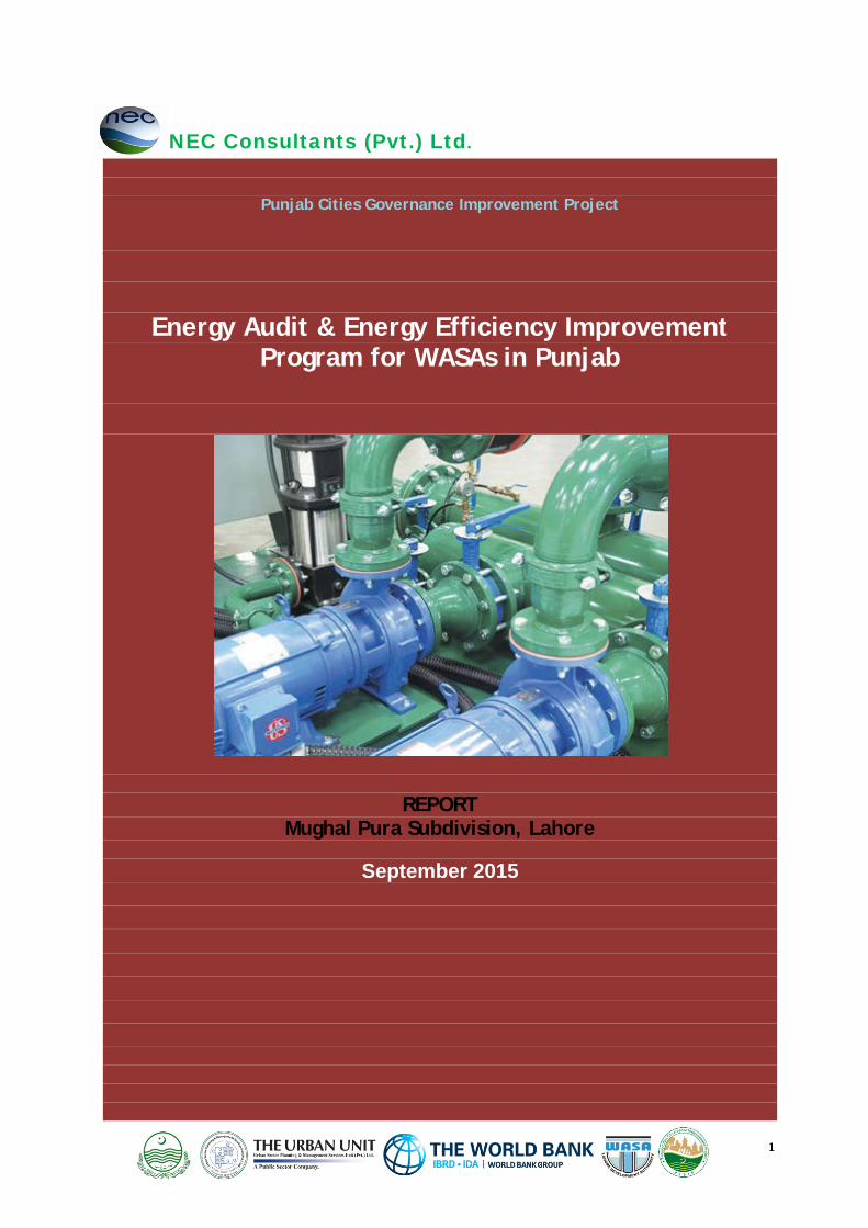
Energy Audit & Energy Efficiency Improvement Program for WASAs in Punjab
REPORT Mughal Pura Subdivision, Lahore
September 2015
NEC Consultants (Pvt.) Ltd.
2
Energy Audit & Energy Efficiency Improvement Program for WASAs in Punjab
September 2015 NEC Consultants Pvt. Ltd Perfect SITE, 22 KM Ferozepur Road, Near Gujju Matta Metro Bus Station, Lahore +92-42-35273741-46, www.nec.com.pk [email protected] This study was assigned by The Urban Unit, Punjab
3
DISCLAIMER No part of this document may be reproduced or transmitted in any form or by any means, electronic or mechanical, including photocopying, recording or information storage and retrieval system, without prior written permission of the USPMSU. A publication of the Urban Sector Planning and Management Services Unit (Private) Limited, the opinion expressed in the document are solely those of the authors and publishing them does not in any way constitute an endorsement of the opinion by the USPMSU.
ACKNOWLEDGEMENTS This report has been prepared by The Urban Unit (Urban Sector Policy & Management Unit), P&D Department, Government of Punjab. The Urban Unit, under the Punjab Cities Governance Improvement Project (PCGIP)-DLI-4 is supporting WASA Lahore for implementing Energy Audit Management Opportunities. Energy management opportunities have been extracted from the energy audits of WASA pumps. The Team Dr. Nasir Javed Engr. Abid Hussainy Engr. Ali Raza Shafqat Ullah Muhammad Rizwan Kashif Shaukat Adnan Khan Editing & Layout By: Ms. Madiha Qamar Printed in Pakistan Copyright: Urban Sector Planning and Management Services Unit (Private) Limited.
4
CONTENTS Contents 4 List of Annexure 4 List of Figures 4 List of Tables 4 List of Acronyms and Abbreviations 5 Glossary 5 1.0 Introduction 7
1.1 Background 7 1.2 Methodology 7 1.3 Scope 8
2.0 Energy Audit Findings 9 2.1 Pumping system efficiency 10 2.2 Electricity consumption trend 12 2.3 Pumping system efficiency improvement potential 13 2.4 Interventions for the improvement of WASA stations 15
LIST OF ANNEXURE
I Energy Audit Reports 2 Selected Pictures
LIST OF FIGURES
I Pumping system efficiency category 12 2 Unit electricity consumption trend 13
LIST OF TABLES
1 Detail of WASAs pumps 8 2 Detail of Mughal Pura subdivision 9 3 Typical overall pumping system efficiency classification 10 4 Detail of motor loading and pumping system efficiency 11 5 Detail of water discharge and electricity consumption 12 6 System energy efficiency potential of pumps 14
7A Interventions & investment required in WASA stations-Mughal Pura Subdivision 16
7B Interventions & investment required in WASA stations- Mughal Pura Subdivision 18
7C Interventions & investment required in WASA stations- Mughal Pura Subdivision 20
5
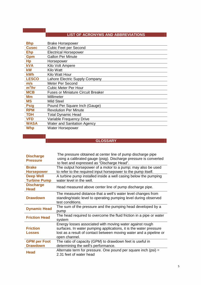
LIST OF ACRONYMS AND ABBREVIATIONS Bhp Brake Horsepower Cusec Cubic Feet per Second Ehp Electrical Horsepower Gpm Gallon Per Minute Hp Horsepower kVA Kilo Volt Ampere kW Kilo Watt kWh Kilo Watt Hour LESCO Lahore Electric Supply Company m/s Meter Per Second m3/hr Cubic Meter Per Hour MCB Fuses or Miniature Circuit Breaker Mm Millimeter MS Mild Steel Psig Pound Per Square Inch (Gauge) RPM Revolution Per Minute TDH Total Dynamic Head VFD Variable Frequency Drive WASA Water and Sanitation Agency Whp Water Horsepower
GLOSSARY
Discharge Pressure
The pressure obtained at center line of pump discharge pipe using a calibrated gauge (psig). Discharge pressure is converted to feet and expressed as “Discharge Head”.
Brake Horsepower
The output horsepower of a motor to a pump; may also be used to refer to the required input horsepower to the pump itself.
Deep Well Turbine Pump
A turbine pump installed inside a well casing below the pumping water level in the well.
Discharge Head Head measured above center line of pump discharge pipe.
Drawdown The measured distance that a well’s water level changes from standing/static level to operating pumping level during observed test conditions.
Dynamic Head The sum of the pressure and the pumping head developed by a pump
Friction Head The head required to overcome the fluid friction in a pipe or water system
Friction Losses
Energy losses associated with moving water against rough surfaces. In water pumping applications, it is the water pressure lost as a result of contact between moving water and a pipeline or open channel.
GPM per Foot Drawdown
The ratio of capacity (GPM) to drawdown feet is useful in determining the well’s performance.
Head Alternate term for pressure. One pound per square inch (psi) = 2.31 feet of water head
6
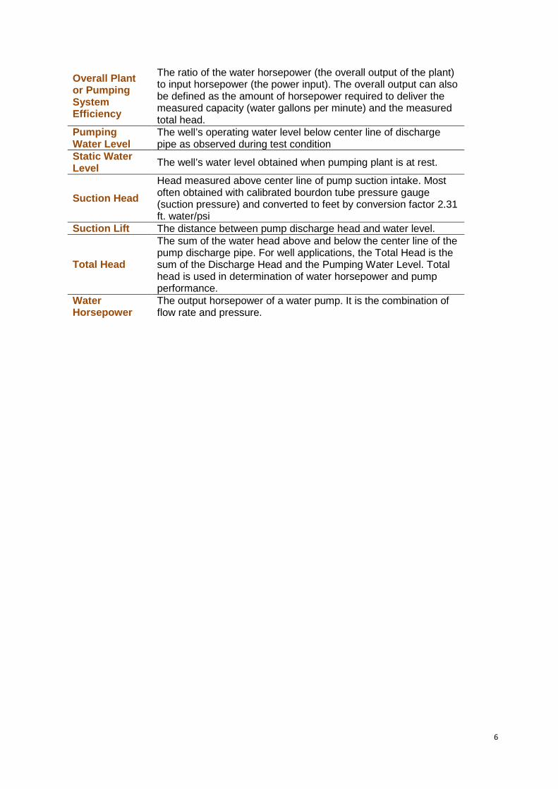
Overall Plant or Pumping System Efficiency
The ratio of the water horsepower (the overall output of the plant) to input horsepower (the power input). The overall output can also be defined as the amount of horsepower required to deliver the measured capacity (water gallons per minute) and the measured total head.
Pumping Water Level
The well’s operating water level below center line of discharge pipe as observed during test condition
Static Water Level The well’s water level obtained when pumping plant is at rest.
Suction Head Head measured above center line of pump suction intake. Most often obtained with calibrated bourdon tube pressure gauge (suction pressure) and converted to feet by conversion factor 2.31 ft. water/psi
Suction Lift The distance between pump discharge head and water level.
Total Head
The sum of the water head above and below the center line of the pump discharge pipe. For well applications, the Total Head is the sum of the Discharge Head and the Pumping Water Level. Total head is used in determination of water horsepower and pump performance.
Water Horsepower
The output horsepower of a water pump. It is the combination of flow rate and pressure.
7
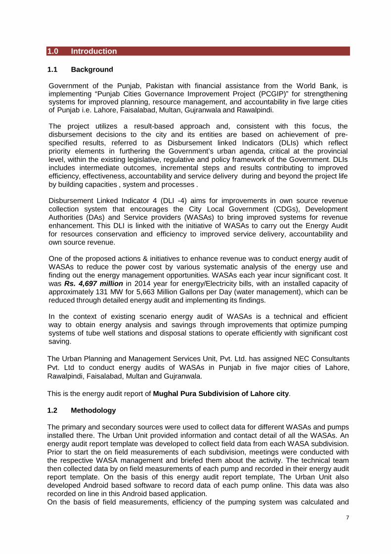
1.0 Introduction 1.1 Background Energy Audit & Energy Efficiency Improvement gram Government of the Punjab, Pakistan with financial assistance from the World Bank, is implementing “Punjab Cities Governance Improvement Project (PCGIP)” for strengthening systems for improved planning, resource management, and accountability in five large cities of Punjab i.e. Lahore, Faisalabad, Multan, Gujranwala and Rawalpindi. The project utilizes a result-based approach and, consistent with this focus, the disbursement decisions to the city and its entities are based on achievement of pre-specified results, referred to as Disbursement linked Indicators (DLIs) which reflect priority elements in furthering the Government’s urban agenda, critical at the provincial level, within the existing legislative, regulative and policy framework of the Government. DLIs includes intermediate outcomes, incremental steps and results contributing to improved efficiency, effectiveness, accountability and service delivery during and beyond the project life by building capacities , system and processes . Disbursement Linked Indicator 4 (DLI -4) aims for improvements in own source revenue collection system that encourages the City Local Government (CDGs), Development Authorities (DAs) and Service providers (WASAs) to bring improved systems for revenue enhancement. This DLI is linked with the initiative of WASAs to carry out the Energy Audit for resources conservation and efficiency to improved service delivery, accountability and own source revenue. One of the proposed actions & initiatives to enhance revenue was to conduct energy audit of WASAs to reduce the power cost by various systematic analysis of the energy use and finding out the energy management opportunities. WASAs each year incur significant cost. It was Rs. 4,697 million in 2014 year for energy/Electricity bills, with an installed capacity of approximately 131 MW for 5,663 Million Gallons per Day (water management), which can be reduced through detailed energy audit and implementing its findings. In the context of existing scenario energy audit of WASAs is a technical and efficient way to obtain energy analysis and savings through improvements that optimize pumping systems of tube well stations and disposal stations to operate efficiently with significant cost saving. The Urban Planning and Management Services Unit, Pvt. Ltd. has assigned NEC Consultants Pvt. Ltd to conduct energy audits of WASAs in Punjab in five major cities of Lahore, Rawalpindi, Faisalabad, Multan and Gujranwala. This is the energy audit report of Mughal Pura Subdivision of Lahore city. 1.2 Methodology The primary and secondary sources were used to collect data for different WASAs and pumps installed there. The Urban Unit provided information and contact detail of all the WASAs. An energy audit report template was developed to collect field data from each WASA subdivision. Prior to start the on field measurements of each subdivision, meetings were conducted with the respective WASA management and briefed them about the activity. The technical team then collected data by on field measurements of each pump and recorded in their energy audit report template. On the basis of this energy audit report template, The Urban Unit also developed Android based software to record data of each pump online. This data was also recorded on line in this Android based application. On the basis of field measurements, efficiency of the pumping system was calculated and
8
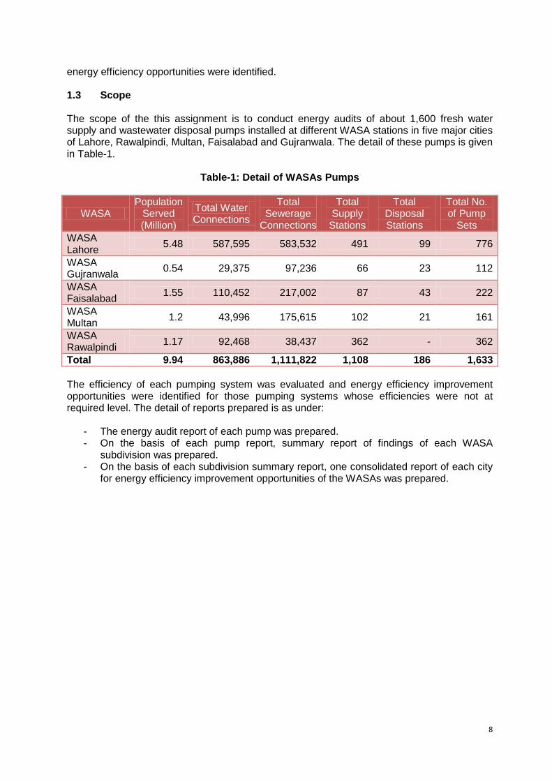
energy efficiency opportunities were identified. 1.3 Scope The scope of the this assignment is to conduct energy audits of about 1,600 fresh water supply and wastewater disposal pumps installed at different WASA stations in five major cities of Lahore, Rawalpindi, Multan, Faisalabad and Gujranwala. The detail of these pumps is given in Table-1.
Table-1: Detail of WASAs Pumps
WASA Population
Served (Million)
Total Water Connections
Total Sewerage
Connections
Total Supply
Stations
Total Disposal Stations
Total No. of Pump
Sets WASA Lahore 5.48 587,595 583,532 491 99 776
WASA Gujranwala 0.54 29,375 97,236 66 23 112
WASA Faisalabad 1.55 110,452 217,002 87 43 222
WASA Multan 1.2 43,996 175,615 102 21 161
WASA Rawalpindi 1.17 92,468 38,437 362 - 362
Total 9.94 863,886 1,111,822 1,108 186 1,633 The efficiency of each pumping system was evaluated and energy efficiency improvement opportunities were identified for those pumping systems whose efficiencies were not at required level. The detail of reports prepared is as under:
- The energy audit report of each pump was prepared. - On the basis of each pump report, summary report of findings of each WASA
subdivision was prepared. - On the basis of each subdivision summary report, one consolidated report of each city
for energy efficiency improvement opportunities of the WASAs was prepared.
9
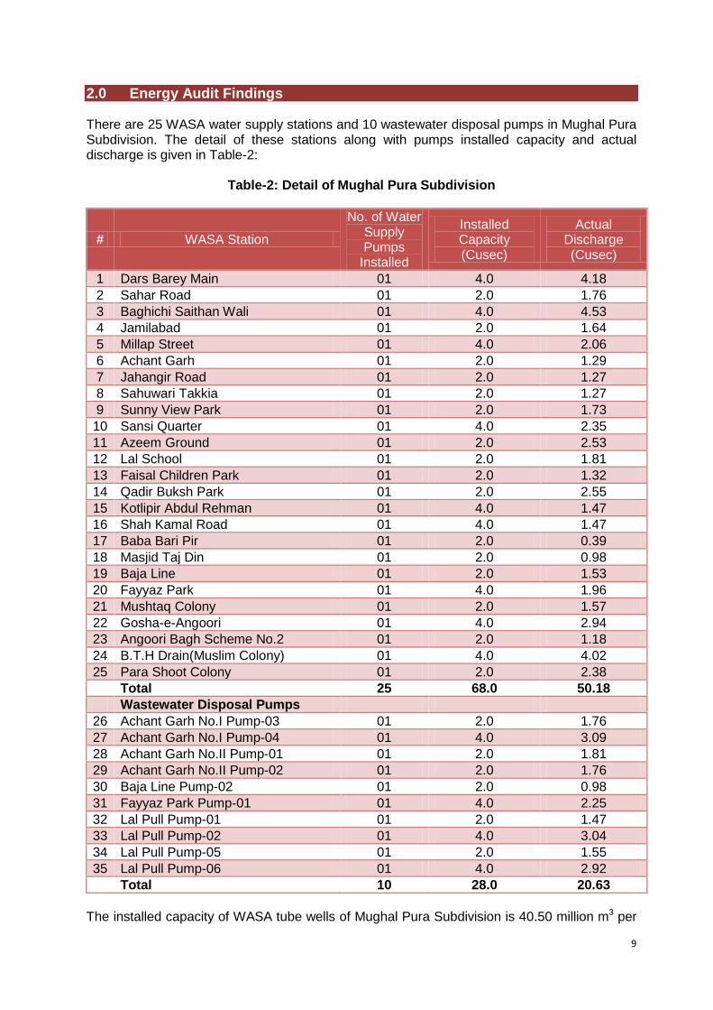
2.0 Energy Audit Findings There are 25 WASA water supply stations and 10 wastewater disposal pumps in Mughal Pura Subdivision. The detail of these stations along with pumps installed capacity and actual discharge is given in Table-2:
Table-2: Detail of Mughal Pura Subdivision
# WASA Station
No. of Water Supply Pumps
Installed
Installed Capacity (Cusec)
Actual Discharge (Cusec)
1 Dars Barey Main 01 4.0 4.18 2 Sahar Road 01 2.0 1.76 3 Baghichi Saithan Wali 01 4.0 4.53 4 Jamilabad 01 2.0 1.64 5 Millap Street 01 4.0 2.06 6 Achant Garh 01 2.0 1.29 7 Jahangir Road 01 2.0 1.27 8 Sahuwari Takkia 01 2.0 1.27 9 Sunny View Park 01 2.0 1.73 10 Sansi Quarter 01 4.0 2.35 11 Azeem Ground 01 2.0 2.53 12 Lal School 01 2.0 1.81 13 Faisal Children Park 01 2.0 1.32 14 Qadir Buksh Park 01 2.0 2.55 15 Kotlipir Abdul Rehman 01 4.0 1.47 16 Shah Kamal Road 01 4.0 1.47 17 Baba Bari Pir 01 2.0 0.39 18 Masjid Taj Din 01 2.0 0.98 19 Baja Line 01 2.0 1.53 20 Fayyaz Park 01 4.0 1.96 21 Mushtaq Colony 01 2.0 1.57 22 Gosha-e-Angoori 01 4.0 2.94 23 Angoori Bagh Scheme No.2 01 2.0 1.18 24 B.T.H Drain(Muslim Colony) 01 4.0 4.02 25 Para Shoot Colony 01 2.0 2.38 Total 25 68.0 50.18 Wastewater Disposal Pumps
26 Achant Garh No.I Pump-03 01 2.0 1.76 27 Achant Garh No.I Pump-04 01 4.0 3.09 28 Achant Garh No.II Pump-01 01 2.0 1.81 29 Achant Garh No.II Pump-02 01 2.0 1.76 30 Baja Line Pump-02 01 2.0 0.98 31 Fayyaz Park Pump-01 01 4.0 2.25 32 Lal Pull Pump-01 01 2.0 1.47 33 Lal Pull Pump-02 01 4.0 3.04 34 Lal Pull Pump-05 01 2.0 1.55 35 Lal Pull Pump-06 01 4.0 2.92 Total 10 28.0 20.63
The installed capacity of WASA tube wells of Mughal Pura Subdivision is 40.50 million m3 per
10
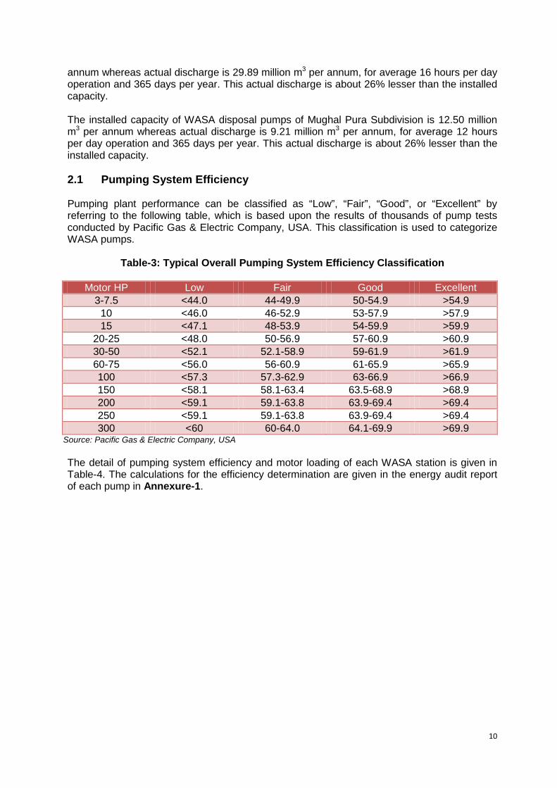
annum whereas actual discharge is 29.89 million m3 per annum, for average 16 hours per day operation and 365 days per year. This actual discharge is about 26% lesser than the installed capacity. The installed capacity of WASA disposal pumps of Mughal Pura Subdivision is 12.50 million m3 per annum whereas actual discharge is 9.21 million m3 per annum, for average 12 hours per day operation and 365 days per year. This actual discharge is about 26% lesser than the installed capacity. 2.1 Pumping System Efficiency Pumping plant performance can be classified as “Low”, “Fair”, “Good”, or “Excellent” by referring to the following table, which is based upon the results of thousands of pump tests conducted by Pacific Gas & Electric Company, USA. This classification is used to categorize WASA pumps.
Table-3: Typical Overall Pumping System Efficiency Classification
Motor HP Low Fair Good Excellent 3-7.5 <44.0 44-49.9 50-54.9 >54.9
10 <46.0 46-52.9 53-57.9 >57.9 15 <47.1 48-53.9 54-59.9 >59.9
20-25 <48.0 50-56.9 57-60.9 >60.9 30-50 <52.1 52.1-58.9 59-61.9 >61.9 60-75 <56.0 56-60.9 61-65.9 >65.9 100 <57.3 57.3-62.9 63-66.9 >66.9 150 <58.1 58.1-63.4 63.5-68.9 >68.9 200 <59.1 59.1-63.8 63.9-69.4 >69.4 250 <59.1 59.1-63.8 63.9-69.4 >69.4 300 <60 60-64.0 64.1-69.9 >69.9
Source: Pacific Gas & Electric Company, USA The detail of pumping system efficiency and motor loading of each WASA station is given in Table-4. The calculations for the efficiency determination are given in the energy audit report of each pump in Annexure-1.
11
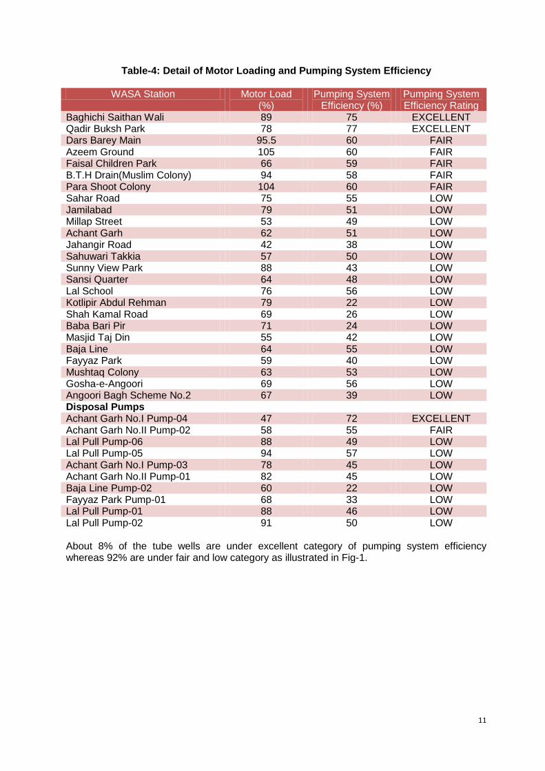
Table-4: Detail of Motor Loading and Pumping System Efficiency
WASA Station Motor Load (%)
Pumping System Efficiency (%)
Pumping System Efficiency Rating
Baghichi Saithan Wali 89 75 EXCELLENT Qadir Buksh Park 78 77 EXCELLENT Dars Barey Main 95.5 60 FAIR Azeem Ground 105 60 FAIR Faisal Children Park 66 59 FAIR B.T.H Drain(Muslim Colony) 94 58 FAIR Para Shoot Colony 104 60 FAIR Sahar Road 75 55 LOW Jamilabad 79 51 LOW Millap Street 53 49 LOW Achant Garh 62 51 LOW Jahangir Road 42 38 LOW Sahuwari Takkia 57 50 LOW Sunny View Park 88 43 LOW Sansi Quarter 64 48 LOW Lal School 76 56 LOW Kotlipir Abdul Rehman 79 22 LOW Shah Kamal Road 69 26 LOW Baba Bari Pir 71 24 LOW Masjid Taj Din 55 42 LOW Baja Line 64 55 LOW Fayyaz Park 59 40 LOW Mushtaq Colony 63 53 LOW Gosha-e-Angoori 69 56 LOW Angoori Bagh Scheme No.2 67 39 LOW Disposal Pumps Achant Garh No.I Pump-04 47 72 EXCELLENT Achant Garh No.II Pump-02 58 55 FAIR Lal Pull Pump-06 88 49 LOW Lal Pull Pump-05 94 57 LOW Achant Garh No.I Pump-03 78 45 LOW Achant Garh No.II Pump-01 82 45 LOW Baja Line Pump-02 60 22 LOW Fayyaz Park Pump-01 68 33 LOW Lal Pull Pump-01 88 46 LOW Lal Pull Pump-02 91 50 LOW About 8% of the tube wells are under excellent category of pumping system efficiency whereas 92% are under fair and low category as illustrated in Fig-1.

12
Figure-1: Pumping System Efficiency Category
About 10% of the operational disposal pumps are under excellent category whereas 90% are under fair and low category of pumping system efficiency. 2.2 Electricity Consumption Trend The detail of annual water discharge and correspondingly electricity consumption and unit electricity consumption of each WASA station is given in Table-5.
Table-5: Detail of Water Discharge and Electricity Consumption
# WASA Station Annual Water
Discharge (m3)
Annual Electricity Consumption
(kWh)
Unit Electricity Consumption
(kWh/m3) 1 Dars Barey Main 2,332,350 577,957 0.25 2 Sahar Road 985,500 247,696 0.25 3 Baghichi Saithan Wali 2,529,450 540,528 0.21 4 Jamilabad 914,325 262,007 0.29 5 Millap Street 1,073,100 298,483 0.28 6 Achant Garh 722,700 204,212 0.28 7 Jahangir Road 949,000 338,334 0.36 8 Sahuwari Takkia 711,750 187,699 0.26 9 Sunny View Park 963,600 288,979 0.30
10 Sansi Quarter 1,314,000 385,305 0.29 11 Azeem Ground 1,412,550 345,674 0.25 12 Lal School 1,012,875 250,999 0.25 13 Faisal Children Park 739,125 217,973 0.30 14 Qadir Buksh Park 1,423,500 256,503 0.18 15 Kotlipir Abdul Rehman 821,250 479,429 0.58 16 Shah Kamal Road 821,250 415,028 0.51 17 Baba Bari Pir 219,000 116,692 0.53 18 Masjid Taj Din 547,500 179,992 0.33 19 Baja Line 854,100 210,817 0.25 20 Fayyaz Park 1,095,000 359,985 0.33 21 Mushtaq Colony 876,000 209,166 0.24
Excellent 8%
Good 0%
Fair 20%
Low 72%
13
22 Gosha-e-Angoori 1,642,500 419,982 0.26 23 Angoori Bagh Scheme No.2 657,000 220,174 0.34 24 B.T.H Drain(Muslim Colony) 2,244,750 568,050 0.25 25 Para Shoot Colony 1,330,425 344,022 0.26 Total 28,192,600 7,925,686 0.28 Disposal Pumps
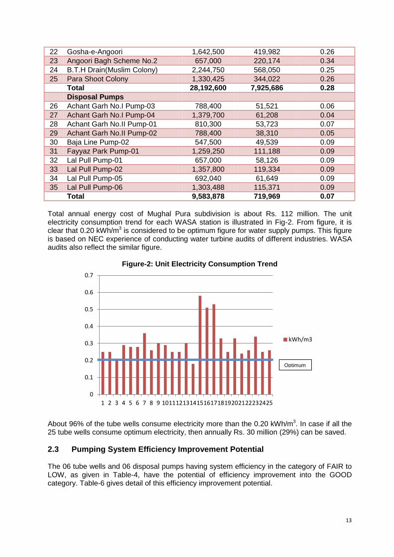
26 Achant Garh No.I Pump-03 788,400 51,521 0.06 27 Achant Garh No.I Pump-04 1,379,700 61,208 0.04 28 Achant Garh No.II Pump-01 810,300 53,723 0.07 29 Achant Garh No.II Pump-02 788,400 38,310 0.05 30 Baja Line Pump-02 547,500 49,539 0.09 31 Fayyaz Park Pump-01 1,259,250 111,188 0.09 32 Lal Pull Pump-01 657,000 58,126 0.09 33 Lal Pull Pump-02 1,357,800 119,334 0.09 34 Lal Pull Pump-05 692,040 61,649 0.09 35 Lal Pull Pump-06 1,303,488 115,371 0.09 Total 9,583,878 719,969 0.07 Total annual energy cost of Mughal Pura subdivision is about Rs. 112 million. The unit electricity consumption trend for each WASA station is illustrated in Fig-2. From figure, it is clear that 0.20 kWh/m3 is considered to be optimum figure for water supply pumps. This figure is based on NEC experience of conducting water turbine audits of different industries. WASA audits also reflect the similar figure.
Figure-2: Unit Electricity Consumption Trend
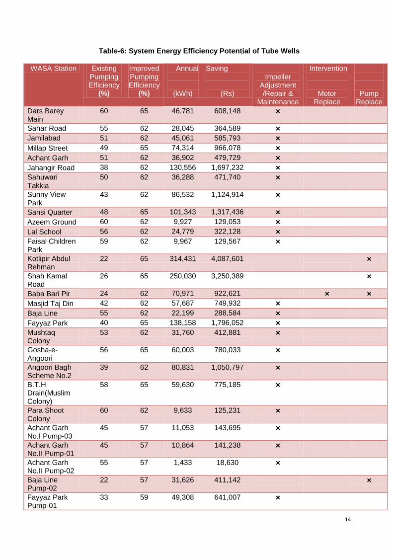
About 96% of the tube wells consume electricity more than the 0.20 kWh/m3. In case if all the 25 tube wells consume optimum electricity, then annually Rs. 30 million (29%) can be saved. 2.3 Pumping System Efficiency Improvement Potential The 06 tube wells and 06 disposal pumps having system efficiency in the category of FAIR to LOW, as given in Table-4, have the potential of efficiency improvement into the GOOD category. Table-6 gives detail of this efficiency improvement potential.
0
0.1
0.2
0.3
0.4
0.5
0.6
0.7
1 2 3 4 5 6 7 8 9 10 11 12 13 14 15 16 17 18 19 20 21 22 23 24 25
kWh/m3
Optimum
14
Table-6: System Energy Efficiency Potential of Tube Wells
WASA Station Existing Pumping Efficiency
(%)
Improved Pumping Efficiency
(%)
Annual
(kWh)
Saving
(Rs)
Impeller
Adjustment /Repair &
Maintenance
Intervention
Motor Replace
Pump Replace
Dars Barey Main
60 65 46,781 608,148 ×
Sahar Road 55 62 28,045 364,589 × Jamilabad 51 62 45,061 585,793 × Millap Street 49 65 74,314 966,078 × Achant Garh 51 62 36,902 479,729 × Jahangir Road 38 62 130,556 1,697,232 × Sahuwari Takkia
50 62 36,288 471,740 ×
Sunny View Park
43 62 86,532 1,124,914 ×
Sansi Quarter 48 65 101,343 1,317,436 × Azeem Ground 60 62 9,927 129,053 × Lal School 56 62 24,779 322,128 × Faisal Children Park
59 62 9,967 129,567 ×
Kotlipir Abdul Rehman
22 65 314,431 4,087,601 ×
Shah Kamal Road
26 65 250,030 3,250,389 ×
Baba Bari Pir 24 62 70,971 922,621 × × Masjid Taj Din 42 62 57,687 749,932 × Baja Line 55 62 22,199 288,584 × Fayyaz Park 40 65 138,158 1,796,052 × Mushtaq Colony
53 62 31,760 412,881 ×
Gosha-e-Angoori
56 65 60,003 780,033 ×
Angoori Bagh Scheme No.2
39 62 80,831 1,050,797 ×
B.T.H Drain(Muslim Colony)
58 65 59,630 775,185 ×
Para Shoot Colony
60 62 9,633 125,231 ×
Achant Garh No.I Pump-03
45 57 11,053 143,695 ×
Achant Garh No.II Pump-01
45 57 10,864 141,238 ×
Achant Garh No.II Pump-02
55 57 1,433 18,630 ×
Baja Line Pump-02
22 57 31,626 411,142 ×
Fayyaz Park Pump-01
33 59 49,308 641,007 ×
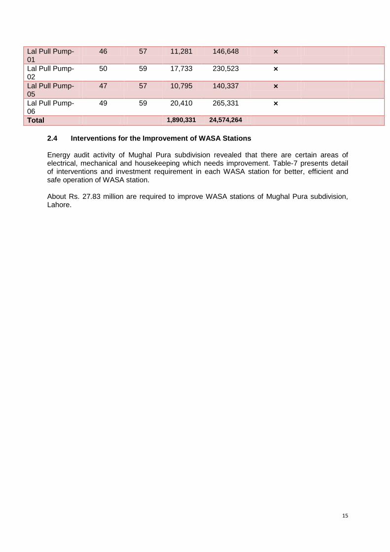
15
Lal Pull Pump-01
46 57 11,281 146,648 ×
Lal Pull Pump-02
50 59 17,733 230,523 ×
Lal Pull Pump-05
47 57 10,795 140,337 ×
Lal Pull Pump-06
49 59 20,410 265,331 ×
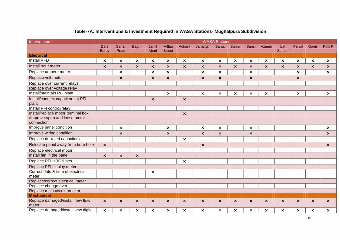
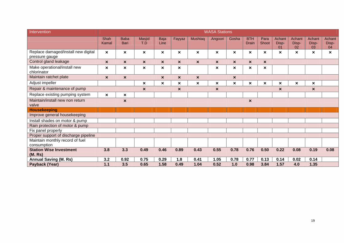
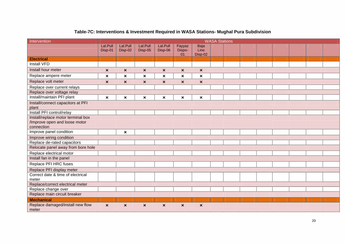
Total 1,890,331 24,574,264 2.4 Interventions for the Improvement of WASA Stations Energy audit activity of Mughal Pura subdivision revealed that there are certain areas of electrical, mechanical and housekeeping which needs improvement. Table-7 presents detail of interventions and investment requirement in each WASA station for better, efficient and safe operation of WASA station. About Rs. 27.83 million are required to improve WASA stations of Mughal Pura subdivision, Lahore.
16
Table-7A: Interventions & Investment Required in WASA Stations- Mughalpura Subdivision
Intervention WASA Stations Dars
Barey Sahar Road
Baghi. Jamil Abad
Millap Street
Achant Jahangir Sahu. Sunny Sansi Azeem Lal School
Faisal Qadir Kotli P
Electrical Install VFD × × × × × × × × × × × × × × × Install hour meter × × × × × × × × × × × × × × × Replace ampere meter × × × × × × × × Replace volt meter × × × × × × × Replace over current relays Replace over voltage relay Install/maintain PFI plant × × × × × × × × Install/connect capacitors at PFI plant
× ×
Install PFI control/relay Install/replace motor terminal box /Improve open and loose motor connection
×
Improve panel condition × × × × × × Improve wiring condition × × × × × × Replace de-rated capacitors × Relocate panel away from bore hole × × × Replace electrical motor Install fan in the panel × × × Replace PFI HRC fuses × Replace PFI display meter Correct date & time of electrical meter
×
Replace/correct electrical meter Replace change over Replace main circuit breaker Mechanical Replace damaged/install new flow meter
× × × × × × × × × × × × × × ×
Replace damaged/install new digital × × × × × × × × × × × × × × ×
17
Intervention WASA Stations Dars
Barey Sahar Road
Baghi. Jamil Abad
Millap Street
Achant Jahangir Sahu. Sunny Sansi Azeem Lal School
Faisal Qadir Kotli P
pressure gauge Control gland leakage × × × × × × × × × × × × Make operational/install new chlorinator
× × × × × × × × × × ×
Maintain ratchet plate × × × × × × Adjust impeller × × × × × × × × × × × Repair & maintenance of pump × × Replace existing pumping system × Maintain/install new non return valve
× × × × × ×
Housekeeping Improve general housekeeping Install shades on motor & pump Rain protection of motor & pump Fix panel properly Proper support of discharge pipeline Maintain monthly record of fuel consumption
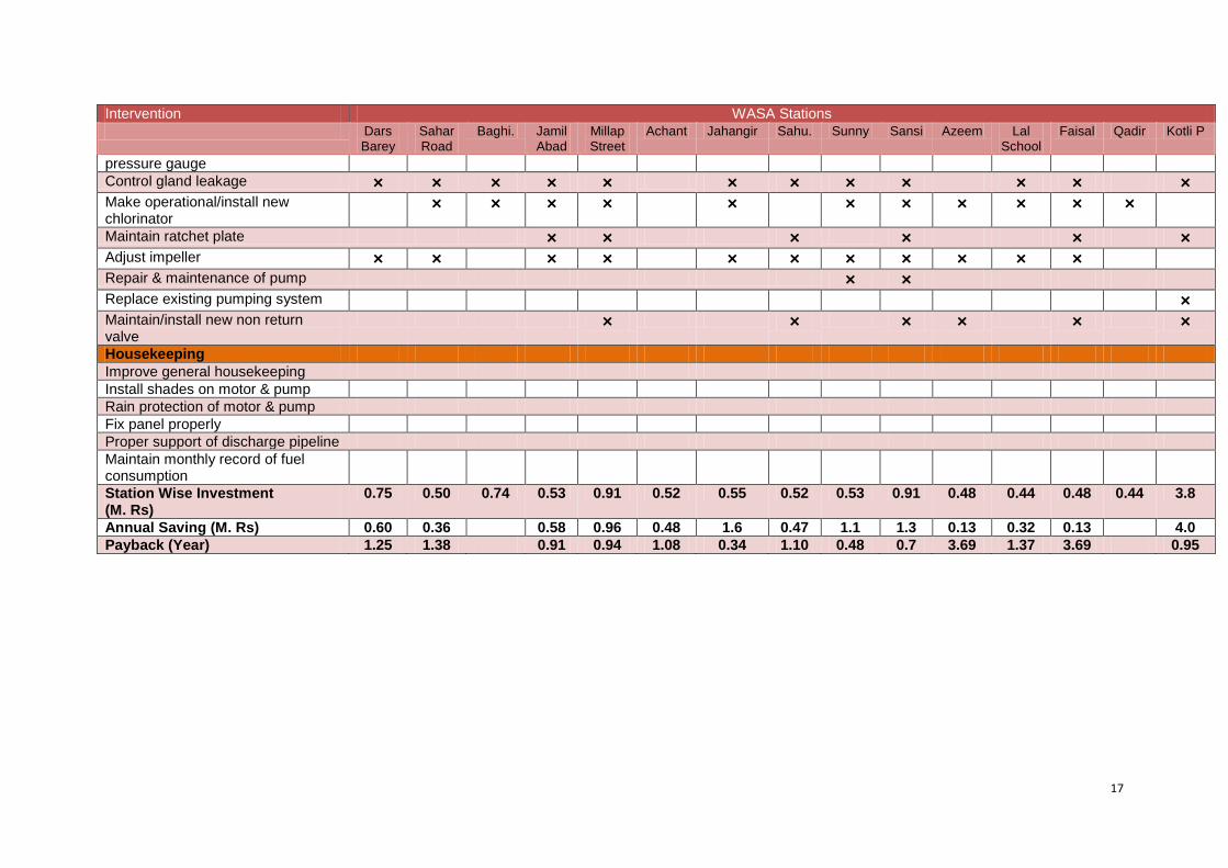
Station Wise Investment (M. Rs)
0.75 0.50 0.74 0.53 0.91 0.52 0.55 0.52 0.53 0.91 0.48 0.44 0.48 0.44 3.8
Annual Saving (M. Rs) 0.60 0.36 0.58 0.96 0.48 1.6 0.47 1.1 1.3 0.13 0.32 0.13 4.0 Payback (Year) 1.25 1.38 0.91 0.94 1.08 0.34 1.10 0.48 0.7 3.69 1.37 3.69 0.95
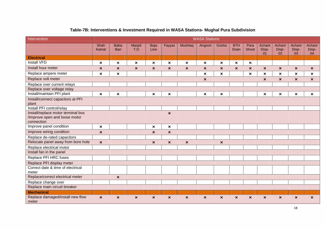
18
Table-7B: Interventions & Investment Required in WASA Stations- Mughal Pura Subdivision Intervention WASA Stations
Shah Kamal
Baba Bari
Masjid T.D
Baja Line
Fayyaz Mushtaq .Angoori Gosha BTH Drain
Para Shoot
Achant Disp-
01
Achant Disp-
02
Achant Disp-
03
Achant Disp-
04 Electrical Install VFD × × × × × × × × × × Install hour meter × × × × × × × × × × × × × × Replace ampere meter × × × × × × × × × Replace volt meter × × × × × Replace over current relays Replace over voltage relay Install/maintain PFI plant × × × × × × × × × × Install/connect capacitors at PFI plant
Install PFI control/relay Install/replace motor terminal box /Improve open and loose motor connection
×
Improve panel condition × × × Improve wiring condition × × × Replace de-rated capacitors Relocate panel away from bore hole × × × × × Replace electrical motor Install fan in the panel Replace PFI HRC fuses Replace PFI display meter Correct date & time of electrical meter
Replace/correct electrical meter × Replace change over Replace main circuit breaker Mechanical Replace damaged/install new flow meter
× × × × × × × × × × × × × ×
19
Intervention WASA Stations
Shah Kamal
Baba Bari
Masjid T.D
Baja Line
Fayyaz Mushtaq .Angoori Gosha BTH Drain
Para Shoot
Achant Disp-
01
Achant Disp-
02
Achant Disp-
03
Achant Disp-
04 Replace damaged/install new digital pressure gauge
× × × × × × × × × × × × × ×
Control gland leakage × × × × × × × × × × Make operational/install new chlorinator
× × × × × × × × ×
Maintain ratchet plate × × × × × × Adjust impeller × × × × × × × × × × × Repair & maintenance of pump × × × × × Replace existing pumping system × × Maintain/install new non return valve
× ×
Housekeeping Improve general housekeeping Install shades on motor & pump Rain protection of motor & pump Fix panel properly Proper support of discharge pipeline Maintain monthly record of fuel consumption
Station Wise Investment (M. Rs)
3.8 3.3 0.49 0.46 0.89 0.43 0.55 0.78 0.76 0.50 0.22 0.08 0.19 0.08
Annual Saving (M. Rs) 3.2 0.92 0.75 0.29 1.8 0.41 1.05 0.78 0.77 0.13 0.14 0.02 0.14 Payback (Year) 1.1 3.5 0.65 1.58 0.49 1.04 0.52 1.0 0.98 3.84 1.57 4.0 1.35
20
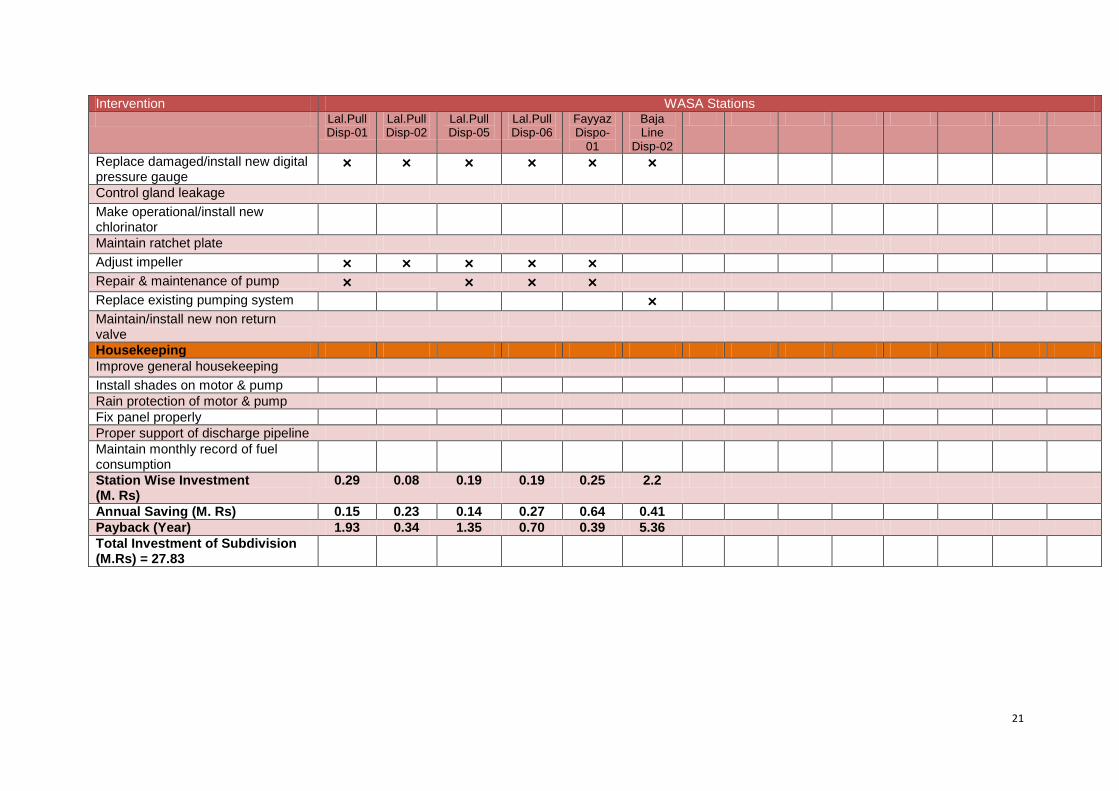
Table-7C: Interventions & Investment Required in WASA Stations- Mughal Pura Subdivision Intervention WASA Stations Lal.Pull
Disp-01 Lal.Pull Disp-02
Lal.Pull Disp-05
Lal.Pull Disp-06
Fayyaz Dispo-
01
Baja Line
Disp-02
Electrical Install VFD Install hour meter × × × × × × Replace ampere meter × × × × × × Replace volt meter × × × × × × Replace over current relays Replace over voltage relay Install/maintain PFI plant × × × × × × Install/connect capacitors at PFI plant
Install PFI control/relay Install/replace motor terminal box /Improve open and loose motor connection
Improve panel condition × Improve wiring condition Replace de-rated capacitors Relocate panel away from bore hole Replace electrical motor Install fan in the panel Replace PFI HRC fuses Replace PFI display meter Correct date & time of electrical meter
Replace/correct electrical meter Replace change over Replace main circuit breaker Mechanical Replace damaged/install new flow meter
× × × × × ×
21
Intervention WASA Stations Lal.Pull
Disp-01 Lal.Pull Disp-02
Lal.Pull Disp-05
Lal.Pull Disp-06
Fayyaz Dispo-
01
Baja Line
Disp-02
Replace damaged/install new digital pressure gauge
× × × × × ×
Control gland leakage Make operational/install new chlorinator
Maintain ratchet plate Adjust impeller × × × × × Repair & maintenance of pump × × × × Replace existing pumping system × Maintain/install new non return valve
Housekeeping Improve general housekeeping Install shades on motor & pump Rain protection of motor & pump Fix panel properly Proper support of discharge pipeline Maintain monthly record of fuel consumption
Station Wise Investment (M. Rs)
0.29 0.08 0.19 0.19 0.25 2.2
Annual Saving (M. Rs) 0.15 0.23 0.14 0.27 0.64 0.41 Payback (Year) 1.93 0.34 1.35 0.70 0.39 5.36 Total Investment of Subdivision (M.Rs) = 27.83
22
ANNEXURE-1
Energy Audit Reports
1 Pumping Station Information
1 Fresh Water Supply
2 Wastewater Disposal
3 Waste Water Treatment Plant
4 Water Treatment Plant
Name of Engineer
WASA Staff Name
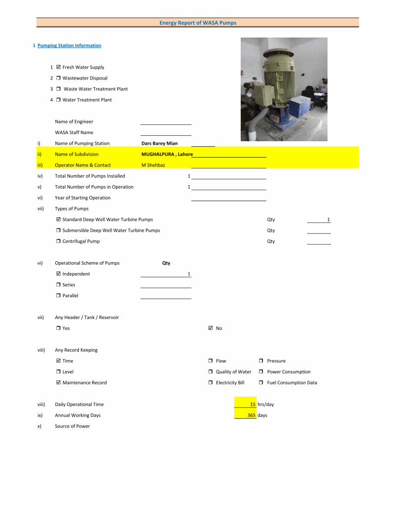
i) Name of Pumping Station Dars Barey Mian
ii) Name of Subdivision MUGHALPURA , Lahore
iii) Operator Name & Contact M Shehbaz
iv) Total Number of Pumps Installed 1
v) Total Number of Pumps in Operation 1
vi) Year of Starting Operation
vii) Types of Pumps
Standard Deep Well Water Turbine Pumps Qty 1
Submersible Deep Well Water Turbine Pumps Qty
Centrifugal Pump Qty
vi) Operational Scheme of Pumps Qty
Independent 1
Series
Parallel
vii) Any Header / Tank / Reservoir
Yes No
viii) Any Record Keeping
Time Flow Pressure
Level Quality of Water Power Consumption
Maintenance Record Electricity Bill Fuel Consumption Data
viii) Daily Operational Time 15 hrs/day
ix) Annual Working Days 365 days
x) Source of Power
Energy Report of WASA Pumps

Primary LESCO Secondary
xi) In Case of Secondary Power Source Fuel Data Details
xii) Operational Hours of Secondary Power Source hrs/day
xiii) Availability of Chlorinator
Yes No
2 Pump Basic Information (Pump Ref # CITY_FWPS/WWDS_Pump #)
i) Type of Pump Deep Well
Submersible
Overhung
Between Bearing
ii) Mounting / Erection
Horizontal Vertical
Foundation
iii) Concrete Bolted Bolted
iv) Lubrication Type
Oil Water
v) Cooling Type
Water Cooled Air Cooled
vi) Number of Stages
Single Multi 4
vii) Pump and Motor Assembly
Direct Coupled Belt / Gear
viii) Source of Suction
Ground Water Aquafier Overhead Tank Underground Tank
Pressurized Source
ix) Pump Discharge Destination
Overhead Tank Drain On Ground Reservoir
Fresh Water Supply Network
Pump Operational Scheme
On / OFF Proportional
x) Pump Flow Control
Throttle VFD Controlled
xi) Any Retrofits ?
Impeller Detail
Casing / Volute Detail
Line Shaft (DW) Detail
Column Sett. (DW) Detail
Motor Replacement Detail
Motor Rewinding Detail
xii) Self Priming
Yes No NA (not applicable)
xiii) Non Clogging (In case of wastewater)
Yes No
xiv) Flowmeter Available
Yes No
xv) Flowmeter Working
Working Properly Malfunctioning (Damaged)
3 Pump Nameplate Data
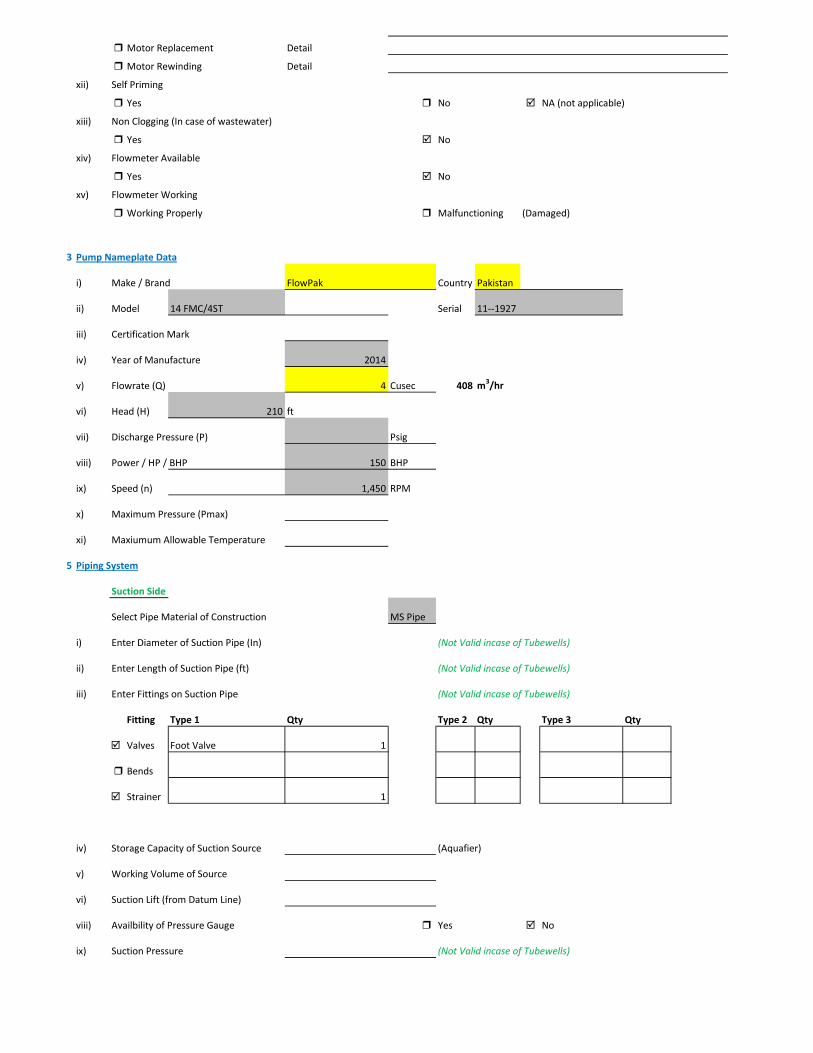
i) Make / Brand FlowPak Country Pakistan
ii) Model 14 FMC/4ST Serial 11--1927
iii) Certification Mark
iv) Year of Manufacture 2014
v) Flowrate (Q) 4 Cusec 408 m3/hr
vi) Head (H) 210 ft
vii) Discharge Pressure (P) Psig
viii) Power / HP / BHP 150 BHP
ix) Speed (n) 1,450 RPM
x) Maximum Pressure (Pmax)
xi) Maxiumum Allowable Temperature
5 Piping System
Suction Side
Select Pipe Material of Construction MS Pipe
i) Enter Diameter of Suction Pipe (In) (Not Valid incase of Tubewells)
ii) Enter Length of Suction Pipe (ft) (Not Valid incase of Tubewells)
iii) Enter Fittings on Suction Pipe (Not Valid incase of Tubewells)
Fitting Type 1 Qty Type 2 Qty Type 3 Qty
Valves Foot Valve 1
Bends
Strainer 1
iv) Storage Capacity of Suction Source (Aquafier)
v) Working Volume of Source
vi) Suction Lift (from Datum Line)
viii) Availbility of Pressure Gauge Yes No
ix) Suction Pressure (Not Valid incase of Tubewells)

Discharge Side
Pipe Material of Construction MS Pipe
i) Diameter of Discharge Pipe 10 inch
ii) Length of Discharge Pipe (Not known as directly connected to network underground)
iii) Fittings on Discharge Pipe
Fitting Type 1 Qty Type 2 Qty Type 3 Qty
Valves Control 1 Check 1
Bends Elbow 1
Strainer
iv) Storage Capacity of Discharge Destination (Not known as directly connected to network underground))
v) Working Volume of Discharge Destination (Not known as directly connected to network underground))
vi) Discharge Elevation (from Datum Line) (In case of no gauge)
vii) Availbility of Pressure Gauge Yes No (Installed by Team)
viii) Discharge Pressure 10 psig
6 Motor Nameplate Data
i) Manufacturer Siemens
ii) Rated kW / hp 150 hp 112.5 kW
iii) Voltage Range (Volts) 380 Volts
iv) Current (Ampere) 214
v) Power Factor (Cos ɸ) 0.85
Efficiency Class
IE3 Eff 1
IE2 Eff 2
IE1 Eff 3
Standard Efficiency
vi) Motor Speed 1,488 RPM
vii) Reference Frequency 50 C/S
viii) Insulation Class F
ix) Motor Frame Size 315 S
x)
7 Electrical System Observations
i) Electrical Meter Reference Number
ii) Meter Reading
iii) Meter Time and Date
Correct FALSE

Lag by Lead by
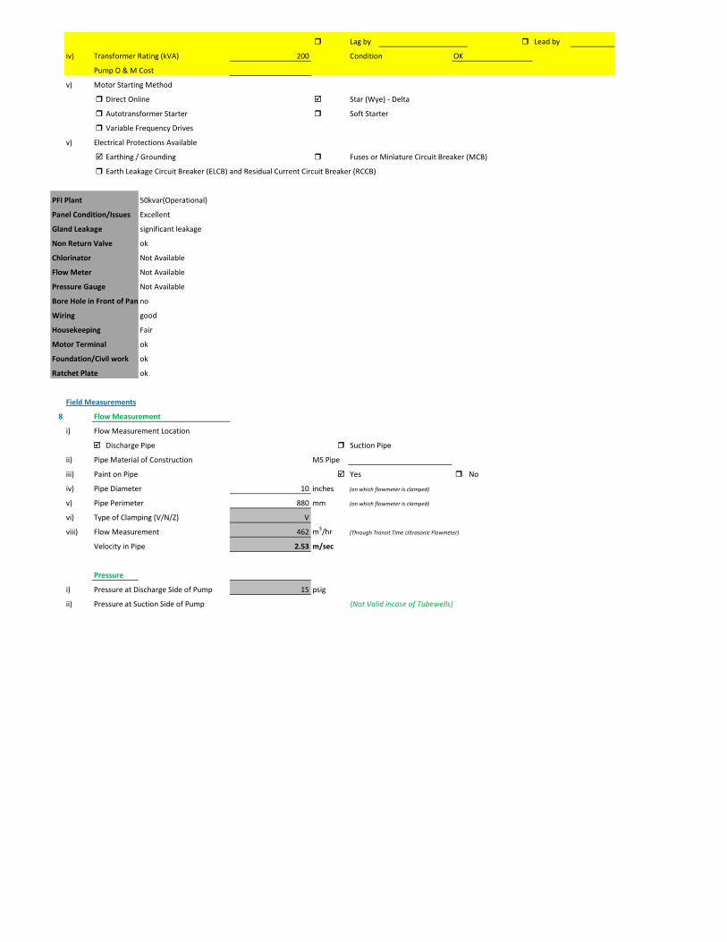
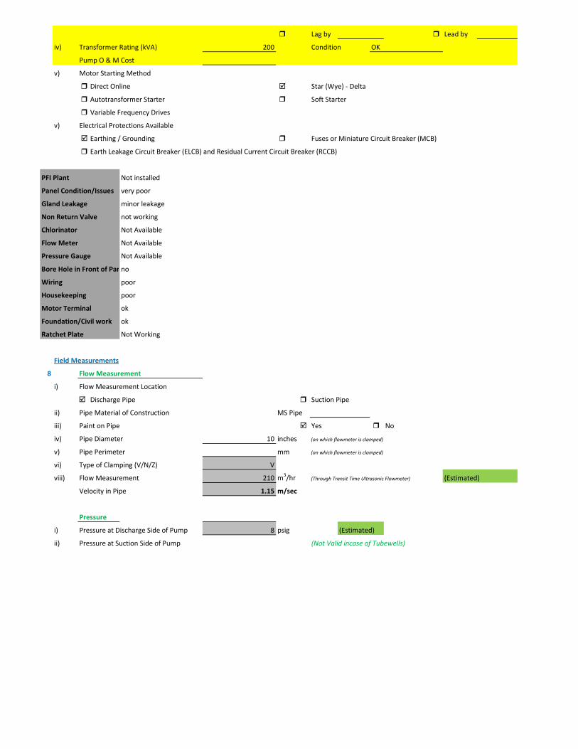
iv) Transformer Rating (kVA) 200 Condition OK
Pump O & M Cost
v) Motor Starting Method
Direct Online Star (Wye) - Delta
Autotransformer Starter Soft Starter
Variable Frequency Drives
v) Electrical Protections Available
Earthing / Grounding Fuses or Miniature Circuit Breaker (MCB)
Earth Leakage Circuit Breaker (ELCB) and Residual Current Circuit Breaker (RCCB)
PFI Plant 50kvar(Operational)
Panel Condition/Issues good
Gland Leakage moderate leakage
Non Return Valve Minor leakage
Chlorinator OK
Flow Meter Not Available
Pressure Gauge Not Available
Bore Hole in Front of PanYes
Wiring good
Housekeeping Fair
Motor Terminal ok
Foundation/Civil work ok
Ratchet Plate ok
Field Measurements
8 Flow Measurement
i) Flow Measurement Location
Discharge Pipe Suction Pipe
ii) Pipe Material of Construction MS Pipe
iii) Paint on Pipe Yes No
iv) Pipe Diameter 10 inches (on which flowmeter is clamped)
v) Pipe Perimeter mm (on which flowmeter is clamped)
vi) Type of Clamping (V/N/Z) V
viii) Flow Measurement 426 m3/hr (Through Transit Time Ultrasonic Flowmeter)
Velocity in Pipe 2.34 m/sec
Pressure
i) Pressure at Discharge Side of Pump 10 psig
ii) Pressure at Suction Side of Pump (Not Valid incase of Tubewells)

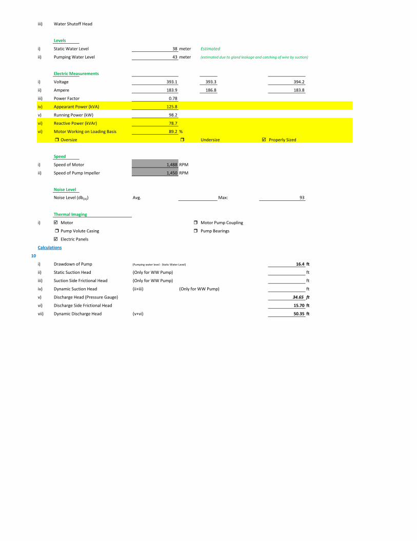
iii) Water Shutoff Head
Levels
i) Static Water Level 38 meter Estimated
ii) Pumping Water Level 43 meter (estimated due to gland leakage and catching of wire by suction)
Electric Measurements
i) Voltage 391.1 391 389.7
ii) Ampere 162.1 161.1 167.5
iii) Power Factor 0.95
iv) Appearant Power (kVA) 110.5
v) Running Power (kW) 105
vi) Reactive Power (kVAr) 34.5
vi) Motor Working on Loading Basis 95.5 %
Oversize Undersize Properly Sized
Speed
i) Speed of Motor 1,488 RPM
ii) Speed of Pump Impeller 1,450 RPM
Noise Level
Noise Level (db(A)) Avg. Max: 93.7
Thermal Imaging
i) Motor Motor Pump Coupling
Pump Volute Casing Pump Bearings
Electric Panels
Calculations
10
i) Drawdown of Pump (Pumping water level - Static Water Level) 16.4 ft
ii) Static Suction Head (Only for WW Pump) ft
iii) Suction Side Frictional Head (Only for WW Pump) ft
iv) Dynamic Suction Head (ii+iii) (Only for WW Pump) ft
v) Discharge Head (Pressure Gauge) 23.1 ft
vi) Discharge Side Frictional Head 13.38 ft
vii) Dynamic Discharge Head (v+vi) 36.48 ft

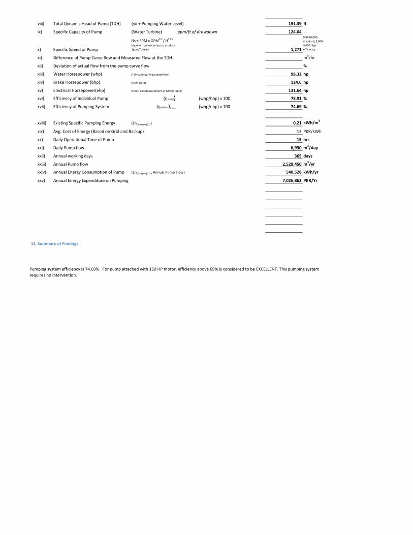
viii) Total Dynamic Head of Pump (TDH) (vii + Pumping Water Level) 177.52 ft
ix) Specific Capacity of Pump (Water Turbine) gpm/ft of drawdown 114.37
x) Specific Speed of Pump
Ns = RPM x GPM0.5 / H0.75
impeller rpm necessary to produce 1gpm/ft head 1,291
500-10,000, standard, 2,000-3,000 high efficiency
xi) Difference of Pump Curve flow and Measured Flow at the TDH m3/hr
xii) Deviation of actual flow from the pump curve flow %
xiii) Water Horsepower (whp) (TDH x Actual Measured Flow) 84.08 hp
xiv) Brake Horsepower (bhp) (OEM Data) 150 hp
xv) Electrical Horsepower(ehp) (Electrical Measurement at Motor input) 140.75 hp
xvi) Efficiency of Individual Pump (ηpump) (whp/bhp) x 100 56.06 %
xvii) Efficiency of Pumping System (ηsystem)Existing (whp/ehp) x 100 59.74 %
xviii) Existing Specific Pumping Energy (En(pumping01)) 0.25 kWh/m3
xix) Avg. Cost of Energy (Based on Grid and Backup) 13 PKR/kWh
xx) Daily Operational Time of Pump 15 hrs
xxi) Daily Pump flow 6,390 m3/day
xxii) Annual working days 365 days
xxiii) Annual Pump flow 2,332,350 m3/yr
xxiv) Annual Energy Consumption of Pump (En(pumping01) x Annual Pump Flow) 577,957 kWh/yr
xxv) Annual Energy Expenditure on Pumping 7,513,447 PKR/Yr
xxvi) Pumping System Efficiency after Improvement 65 %
xxvii) Water Flow after Efficiency Improvement 464 m3/hr
xxviii) Specific Energy Consumption at New Efficiency 0.23 kWh/m3
xxix) Potential of Energy Reduction 8.09 %
xxx) Reduced Annual Energy Consumption at Improved Efficiency 46,781 kWh/yr
xxxi) Annual Financial Saving on Pumping 608,148 PKR/Yr
11 Summary of Findings
Pumping system efficiency is 59.74%. For pump attached with 150 HP motor, efficiency between 58.1 - 63.4% is considered to be FAIR (>
68.9 is excellent). This pumping system requires impeller adjustment. It is estimated that this impeller adjustment would increase pumping efficiency from 59.74% to 65% which is in the range of GOOD efficiency. This efficiency improvement will save about Rs. 608,148 per year.
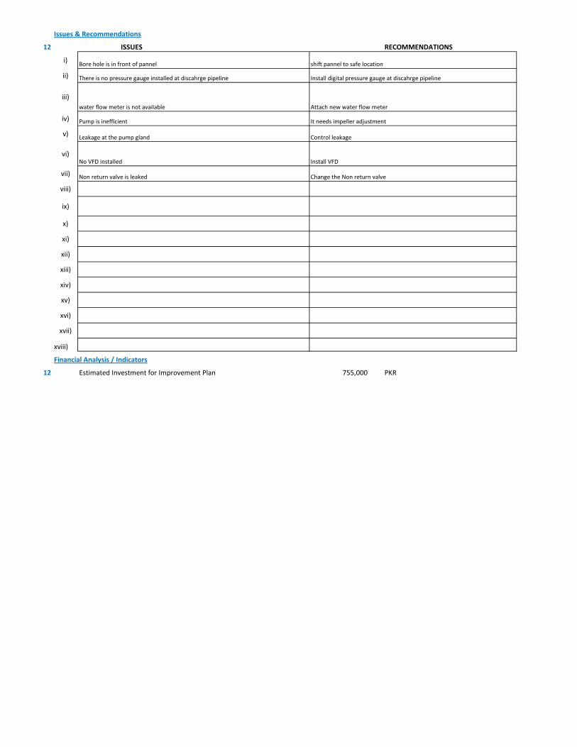
Issues & Recommendations
12 ISSUES RECOMMENDATIONS
i)
ii)
iii)
iv)
v)
vi)
vii)
viii)
ix)
x)
xi)
xii)
xiii)
xiv)
xv)
xvi)
xvii)
xviii)
Financial Analysis / Indicators
12 Estimated Investment for Improvement Plan 755,000 PKR
Install VFDNo VFD installed
Non return valve is leaked Change the Non return valve
Bore hole is in front of pannel shift pannel to safe location
Control leakageLeakage at the pump gland
It needs impeller adjustment Pump is inefficient
There is no pressure gauge installed at discahrge pipeline Install digital pressure gauge at discahrge pipeline
water flow meter is not available Attach new water flow meter
1 Pumping Station Information
1 Fresh Water Supply
2 Wastewater Disposal
3 Waste Water Treatment Plant
4 Water Treatment Plant
Name of Engineer
WASA Staff Name
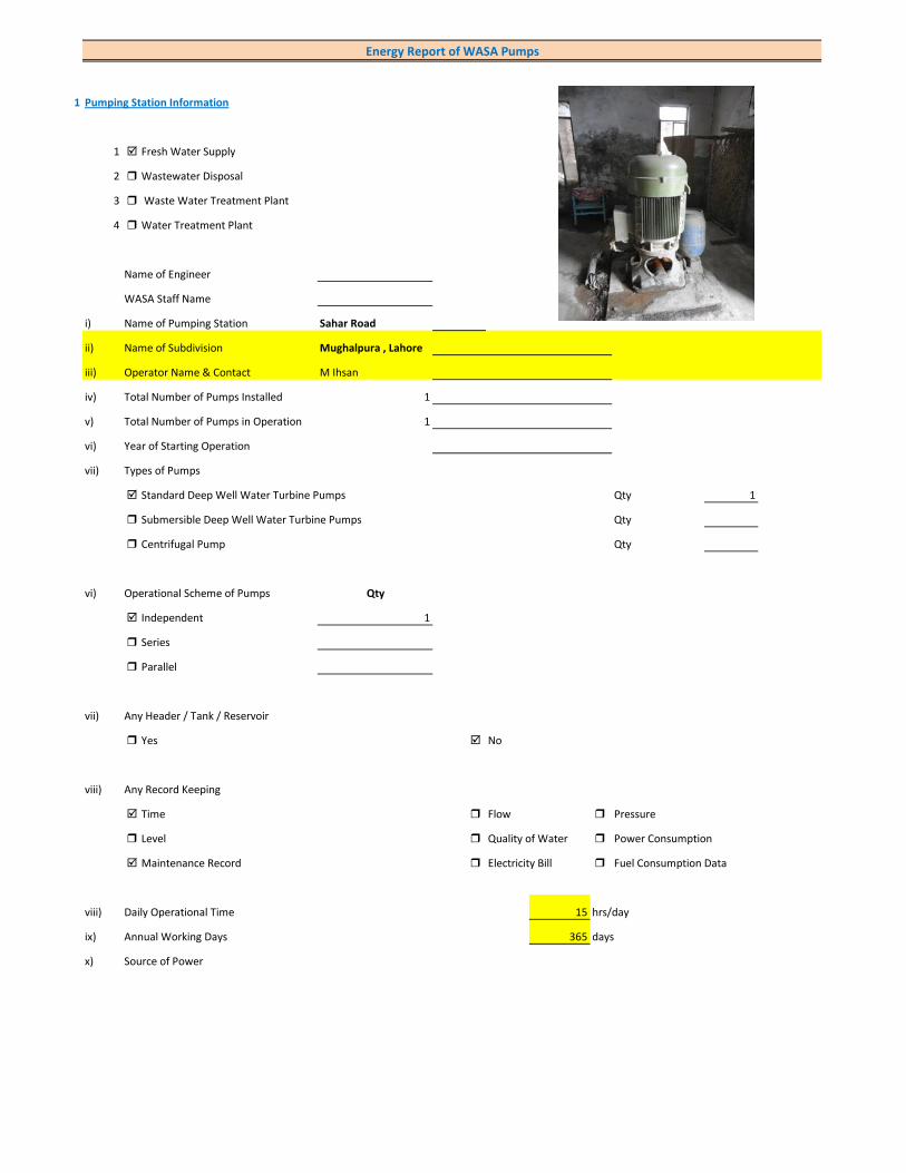
i) Name of Pumping Station Sahar Road
ii) Name of Subdivision Mughalpura , Lahore
iii) Operator Name & Contact M Ihsan
iv) Total Number of Pumps Installed 1
v) Total Number of Pumps in Operation 1
vi) Year of Starting Operation
vii) Types of Pumps
Standard Deep Well Water Turbine Pumps Qty 1
Submersible Deep Well Water Turbine Pumps Qty
Centrifugal Pump Qty
vi) Operational Scheme of Pumps Qty
Independent 1
Series
Parallel
vii) Any Header / Tank / Reservoir
Yes No
viii) Any Record Keeping
Time Flow Pressure
Level Quality of Water Power Consumption
Maintenance Record Electricity Bill Fuel Consumption Data
viii) Daily Operational Time 15 hrs/day
ix) Annual Working Days 365 days
x) Source of Power
Energy Report of WASA Pumps
Primary LESCO Secondary
xi) In Case of Secondary Power Source Fuel Data Details
xii) Operational Hours of Secondary Power Source hrs/day
xiii) Availability of Chlorinator
Yes Not Working No
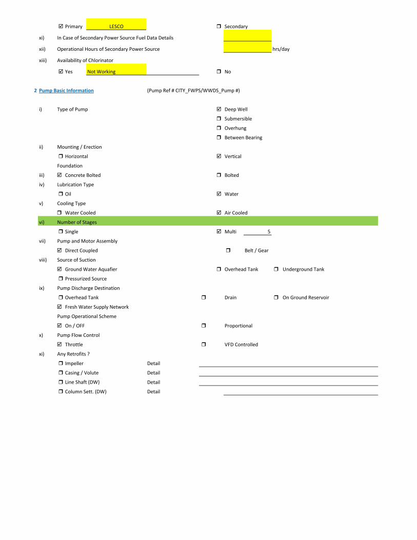
2 Pump Basic Information (Pump Ref # CITY_FWPS/WWDS_Pump #)
i) Type of Pump Deep Well
Submersible
Overhung
Between Bearing
ii) Mounting / Erection
Horizontal Vertical
Foundation
iii) Concrete Bolted Bolted
iv) Lubrication Type
Oil Water
v) Cooling Type
Water Cooled Air Cooled
vi) Number of Stages
Single Multi 5
vii) Pump and Motor Assembly
Direct Coupled Belt / Gear
viii) Source of Suction
Ground Water Aquafier Overhead Tank Underground Tank
Pressurized Source
ix) Pump Discharge Destination
Overhead Tank Drain On Ground Reservoir
Fresh Water Supply Network
Pump Operational Scheme
On / OFF Proportional
x) Pump Flow Control
Throttle VFD Controlled
xi) Any Retrofits ?
Impeller Detail
Casing / Volute Detail
Line Shaft (DW) Detail
Column Sett. (DW) Detail

Motor Replacement Detail
Motor Rewinding Detail
xii) Self Priming
Yes No NA (not applicable)
xiii) Non Clogging (In case of wastewater)
Yes No
xiv) Flowmeter Available
Yes No
xv) Flowmeter Working
Working Properly Malfunctioning (Damaged)
3 Pump Nameplate Data
i) Make / Brand Country
ii) Model Serial
iii) Certification Mark
iv) Year of Manufacture
v) Flowrate (Q) 2 Cusec 204 m3/hr
vi) Head (H) ft
vii) Discharge Pressure (P) Psig
viii) Power / HP / BHP BHP (Estimated)
ix) Speed (n) RPM
x) Maximum Pressure (Pmax)
xi) Maxiumum Allowable Temperature
5 Piping System
Suction Side
Select Pipe Material of Construction MS Pipe
i) Enter Diameter of Suction Pipe (In) (Not Valid incase of Tubewells)
ii) Enter Length of Suction Pipe (ft) (Not Valid incase of Tubewells)
iii) Enter Fittings on Suction Pipe (Not Valid incase of Tubewells)
Fitting Type 1 Qty Type 2 Qty Type 3 Qty
Valves Foot Valve 1
Bends
Strainer 1
iv) Storage Capacity of Suction Source (Aquafier)
v) Working Volume of Source
vi) Suction Lift (from Datum Line)
viii) Availbility of Pressure Gauge Yes No
ix) Suction Pressure (Not Valid incase of Tubewells)

Discharge Side
Pipe Material of Construction MS Pipe
i) Diameter of Discharge Pipe 8 inch
ii) Length of Discharge Pipe (Not known as directly connected to network underground)
iii) Fittings on Discharge Pipe
Fitting Type 1 Qty Type 2 Qty Type 3 Qty
Valves Control 1 Check 1
Bends Elbow 1
Strainer
iv) Storage Capacity of Discharge Destination (Not known as directly connected to network underground))
v) Working Volume of Discharge Destination (Not known as directly connected to network underground))
vi) Discharge Elevation (from Datum Line) (In case of no gauge)
vii) Availbility of Pressure Gauge Yes No (Installed by Team)
viii) Discharge Pressure psig
6 Motor Nameplate Data
i) Manufacturer Siemens
ii) Rated kW / hp 80 hp 60 kW
iii) Voltage Range (Volts) 380 Volts
iv) Current (Ampere) 115
v) Power Factor (Cos ɸ) 0.85
Efficiency Class
IE3 Eff 1
IE2 Eff 2
IE1 Eff 3
Standard Efficiency
vi) Motor Speed 1,488 RPM
vii) Reference Frequency 50 C/S
viii) Insulation Class F
ix) Motor Frame Size 250 M
x)
7 Electrical System Observations
i) Electrical Meter Reference Number
ii) Meter Reading
iii) Meter Time and Date
Correct FALSE
Lag by Lead by
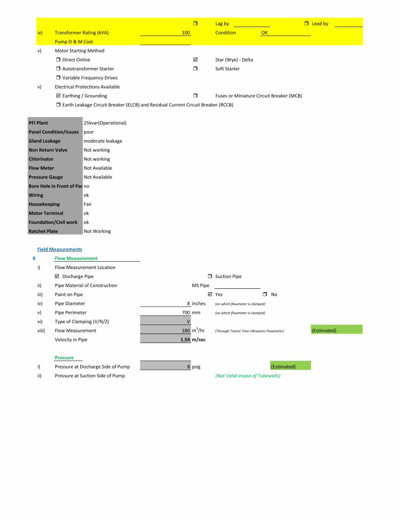
iv) Transformer Rating (kVA) 100 Condition OK
Pump O & M Cost
v) Motor Starting Method
Direct Online Star (Wye) - Delta
Autotransformer Starter Soft Starter
Variable Frequency Drives
v) Electrical Protections Available
Earthing / Grounding Fuses or Miniature Circuit Breaker (MCB)
Earth Leakage Circuit Breaker (ELCB) and Residual Current Circuit Breaker (RCCB)
PFI Plant 25kvar(Operational)
Panel Condition/Issues poor
Gland Leakage moderate leakage
Non Return Valve Not working
Chlorinator Not working
Flow Meter Not Available
Pressure Gauge Not Available
Bore Hole in Front of Panno
Wiring ok
Housekeeping Fair
Motor Terminal ok
Foundation/Civil work ok
Ratchet Plate Not Working
Field Measurements
8 Flow Measurement
i) Flow Measurement Location
Discharge Pipe Suction Pipe
ii) Pipe Material of Construction MS Pipe
iii) Paint on Pipe Yes No
iv) Pipe Diameter 8 inches (on which flowmeter is clamped)
v) Pipe Perimeter 700 mm (on which flowmeter is clamped)
vi) Type of Clamping (V/N/Z) V
viii) Flow Measurement 180 m3/hr (Through Transit Time Ultrasonic Flowmeter) (Estimated)
Velocity in Pipe 1.54 m/sec
Pressure
i) Pressure at Discharge Side of Pump 8 psig (Estimated)
ii) Pressure at Suction Side of Pump (Not Valid incase of Tubewells)

iii) Water Shutoff Head
Levels
i) Static Water Level 38 meter Estimated
ii) Pumping Water Level 43 meter (estimated due to gland leakage and catching of wire by suction)
Electric Measurements
i) Voltage 413 410.5 411.9
ii) Ampere 86 91 86.4
iii) Power Factor 0.72
iv) Appearant Power (kVA) 62.5
v) Running Power (kW) 45
vi) Reactive Power (kVAr) 43.4
vi) Motor Working on Loading Basis 75.1 %
Oversize Undersize Properly Sized
Speed
i) Speed of Motor 1,488 RPM
ii) Speed of Pump Impeller RPM
Noise Level
Noise Level (db(A)) Avg. Max: 89.3
Thermal Imaging
i) Motor Motor Pump Coupling
Pump Volute Casing Pump Bearings
Electric Panels
Calculations
10
i) Drawdown of Pump (Pumping water level - Static Water Level) 16.4 ft
ii) Static Suction Head (Only for WW Pump) ft
iii) Suction Side Frictional Head (Only for WW Pump) ft
iv) Dynamic Suction Head (ii+iii) (Only for WW Pump) ft
v) Discharge Head (Pressure Gauge) 18.48 ft
vi) Discharge Side Frictional Head 6.19 ft
vii) Dynamic Discharge Head (v+vi) 24.67 ft
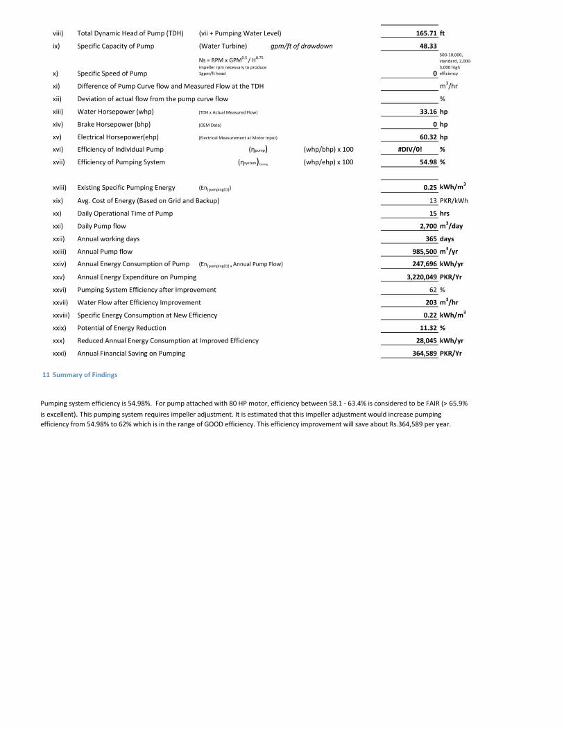
viii) Total Dynamic Head of Pump (TDH) (vii + Pumping Water Level) 165.71 ft
ix) Specific Capacity of Pump (Water Turbine) gpm/ft of drawdown 48.33
x) Specific Speed of Pump
Ns = RPM x GPM0.5 / H0.75
impeller rpm necessary to produce 1gpm/ft head 0
500-10,000, standard, 2,000-3,000 high efficiency
xi) Difference of Pump Curve flow and Measured Flow at the TDH m3/hr
xii) Deviation of actual flow from the pump curve flow %
xiii) Water Horsepower (whp) (TDH x Actual Measured Flow) 33.16 hp
xiv) Brake Horsepower (bhp) (OEM Data) 0 hp
xv) Electrical Horsepower(ehp) (Electrical Measurement at Motor input) 60.32 hp
xvi) Efficiency of Individual Pump (ηpump) (whp/bhp) x 100 #DIV/0! %
xvii) Efficiency of Pumping System (ηsystem)Existing (whp/ehp) x 100 54.98 %
xviii) Existing Specific Pumping Energy (En(pumping01)) 0.25 kWh/m3
xix) Avg. Cost of Energy (Based on Grid and Backup) 13 PKR/kWh
xx) Daily Operational Time of Pump 15 hrs
xxi) Daily Pump flow 2,700 m3/day
xxii) Annual working days 365 days
xxiii) Annual Pump flow 985,500 m3/yr
xxiv) Annual Energy Consumption of Pump (En(pumping01) x Annual Pump Flow) 247,696 kWh/yr
xxv) Annual Energy Expenditure on Pumping 3,220,049 PKR/Yr
xxvi) Pumping System Efficiency after Improvement 62 %
xxvii) Water Flow after Efficiency Improvement 203 m3/hr
xxviii) Specific Energy Consumption at New Efficiency 0.22 kWh/m3
xxix) Potential of Energy Reduction 11.32 %
xxx) Reduced Annual Energy Consumption at Improved Efficiency 28,045 kWh/yr
xxxi) Annual Financial Saving on Pumping 364,589 PKR/Yr
11 Summary of Findings
Pumping system efficiency is 54.98%. For pump attached with 80 HP motor, efficiency between 58.1 - 63.4% is considered to be FAIR (> 65.9%
is excellent). This pumping system requires impeller adjustment. It is estimated that this impeller adjustment would increase pumping efficiency from 54.98% to 62% which is in the range of GOOD efficiency. This efficiency improvement will save about Rs.364,589 per year.
Issues & Recommendations
12 ISSUES RECOMMENDATIONS
i)
ii)
iii)
iv)
v)
vi)
vii)
viii)
ix)
x)
xi)
xii)
xiii)
xiv)
xv)
xvi)
xvii)
xviii)
Financial Analysis / Indicators
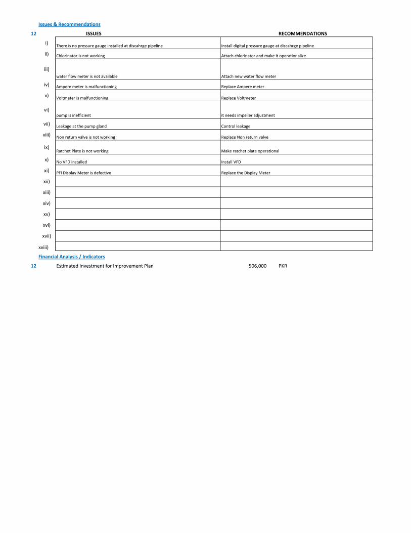
12 Estimated Investment for Improvement Plan 506,000 PKR
Ratchet Plate is not working Make ratchet plate operational
No VFD installed Install VFD
PFI Display Meter is defective Replace the Display Meter
Replace Non return valveNon return valve is not working
water flow meter is not available Attach new water flow meter
Replace Voltmeter Voltmeter is malfunctioning
Replace Ampere meterAmpere meter is malfunctioning
Chlorinator is not working Attach chlorinator and make it operationalize
pump is inefficient it needs impeller adjustment
There is no pressure gauge installed at discahrge pipeline Install digital pressure gauge at discahrge pipeline
Leakage at the pump gland Control leakage
1 Pumping Station Information
1 Fresh Water Supply
2 Wastewater Disposal
3 Waste Water Treatment Plant
4 Water Treatment Plant
Name of Engineer
WASA Staff Name
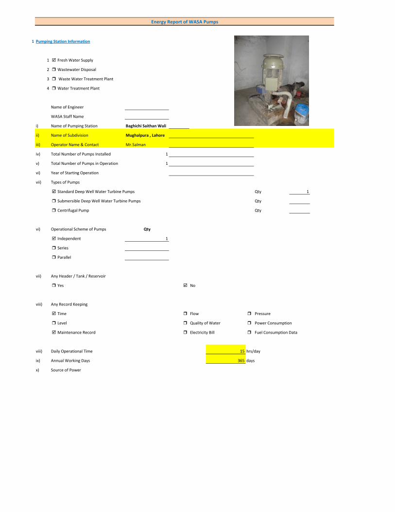
i) Name of Pumping Station Baghichi Saithan Wali
ii) Name of Subdivision Mughalpura , Lahore
iii) Operator Name & Contact Mr.Salman
iv) Total Number of Pumps Installed 1
v) Total Number of Pumps in Operation 1
vi) Year of Starting Operation
vii) Types of Pumps
Standard Deep Well Water Turbine Pumps Qty 1
Submersible Deep Well Water Turbine Pumps Qty
Centrifugal Pump Qty
vi) Operational Scheme of Pumps Qty
Independent 1
Series
Parallel
vii) Any Header / Tank / Reservoir
Yes No
viii) Any Record Keeping
Time Flow Pressure
Level Quality of Water Power Consumption
Maintenance Record Electricity Bill Fuel Consumption Data
viii) Daily Operational Time 15 hrs/day
ix) Annual Working Days 365 days
x) Source of Power
Energy Report of WASA Pumps
Primary LESCO Secondary
xi) In Case of Secondary Power Source Fuel Data Details
xii) Operational Hours of Secondary Power Source hrs/day
xiii) Availability of Chlorinator
Yes No
2 Pump Basic Information (Pump Ref # CITY_FWPS/WWDS_Pump #)
i) Type of Pump Deep Well
Submersible
Overhung
Between Bearing
ii) Mounting / Erection
Horizontal Vertical
Foundation
iii) Concrete Bolted Bolted
iv) Lubrication Type
Oil Water
v) Cooling Type
Water Cooled Air Cooled
vi) Number of Stages
Single Multi 4
vii) Pump and Motor Assembly
Direct Coupled Belt / Gear
viii) Source of Suction
Ground Water Aquafier Overhead Tank Underground Tank
Pressurized Source
ix) Pump Discharge Destination
Overhead Tank Drain On Ground Reservoir
Fresh Water Supply Network
Pump Operational Scheme
On / OFF Proportional
x) Pump Flow Control
Throttle VFD Controlled
xi) Any Retrofits ?
Impeller Detail
Casing / Volute Detail
Line Shaft (DW) Detail
Column Sett. (DW) Detail
Motor Replacement Detail
Motor Rewinding Detail
xii) Self Priming
Yes No NA (not applicable)
xiii) Non Clogging (In case of wastewater)
Yes No
xiv) Flowmeter Available
Yes No
xv) Flowmeter Working
Working Properly Malfunctioning (Damaged)
3 Pump Nameplate Data
i) Make / Brand KSB Pumps Country Pakistan
ii) Model B 14 B/4 Serial 99723976047300
iii) Certification Mark
iv) Year of Manufacture 2013
v) Flowrate (Q) 4 Cusec 408 m3/hr
vi) Head (H) 210 ft
vii) Discharge Pressure (P) Psig
viii) Power / HP / BHP 124.6 BHP
ix) Speed (n) 1,450 RPM
x) Maximum Pressure (Pmax)
xi) Maxiumum Allowable Temperature
5 Piping System
Suction Side
Select Pipe Material of Construction MS Pipe
i) Enter Diameter of Suction Pipe (In) (Not Valid incase of Tubewells)
ii) Enter Length of Suction Pipe (ft) (Not Valid incase of Tubewells)
iii) Enter Fittings on Suction Pipe (Not Valid incase of Tubewells)
Fitting Type 1 Qty Type 2 Qty Type 3 Qty
Valves Foot Valve 1
Bends
Strainer 1
iv) Storage Capacity of Suction Source (Aquafier)
v) Working Volume of Source
vi) Suction Lift (from Datum Line)
viii) Availbility of Pressure Gauge Yes No
ix) Suction Pressure (Not Valid incase of Tubewells)
Discharge Side
Pipe Material of Construction MS Pipe
i) Diameter of Discharge Pipe 10 inch
ii) Length of Discharge Pipe (Not known as directly connected to network underground)
iii) Fittings on Discharge Pipe
Fitting Type 1 Qty Type 2 Qty Type 3 Qty
Valves Control 1 Check 1
Bends Elbow 1
Strainer
iv) Storage Capacity of Discharge Destination (Not known as directly connected to network underground))
v) Working Volume of Discharge Destination (Not known as directly connected to network underground))
vi) Discharge Elevation (from Datum Line) (In case of no gauge)
vii) Availbility of Pressure Gauge Yes No (Installed by Team)
viii) Discharge Pressure 15 psig
6 Motor Nameplate Data
i) Manufacturer Siemens
ii) Rated kW / hp 150 hp 112.5 kW
iii) Voltage Range (Volts) 380 Volts
iv) Current (Ampere) 214
v) Power Factor (Cos ɸ) 0.85
Efficiency Class
IE3 Eff 1
IE2 Eff 2
IE1 Eff 3
Standard Efficiency
vi) Motor Speed 1,488 RPM
vii) Reference Frequency 50 C/S
viii) Insulation Class F
ix) Motor Frame Size 315 M
x)
7 Electrical System Observations
i) Electrical Meter Reference Number
ii) Meter Reading
iii) Meter Time and Date
Correct FALSE
Lag by Lead by
iv) Transformer Rating (kVA) 200 Condition OK
Pump O & M Cost
v) Motor Starting Method
Direct Online Star (Wye) - Delta
Autotransformer Starter Soft Starter
Variable Frequency Drives
v) Electrical Protections Available
Earthing / Grounding Fuses or Miniature Circuit Breaker (MCB)
Earth Leakage Circuit Breaker (ELCB) and Residual Current Circuit Breaker (RCCB)
PFI Plant 50kvar(Operational)
Panel Condition/Issues Excellent
Gland Leakage significant leakage
Non Return Valve ok
Chlorinator Not Available
Flow Meter Not Available
Pressure Gauge Not Available
Bore Hole in Front of Pan no
Wiring good
Housekeeping Fair
Motor Terminal ok
Foundation/Civil work ok
Ratchet Plate ok
Field Measurements
8 Flow Measurement
i) Flow Measurement Location
Discharge Pipe Suction Pipe
ii) Pipe Material of Construction MS Pipe
iii) Paint on Pipe Yes No
iv) Pipe Diameter 10 inches (on which flowmeter is clamped)
v) Pipe Perimeter 880 mm (on which flowmeter is clamped)
vi) Type of Clamping (V/N/Z) V
viii) Flow Measurement 462 m3/hr (Through Transit Time Ultrasonic Flowmeter)
Velocity in Pipe 2.53 m/sec
Pressure
i) Pressure at Discharge Side of Pump 15 psig
ii) Pressure at Suction Side of Pump (Not Valid incase of Tubewells)
iii) Water Shutoff Head
Levels
i) Static Water Level 38 meter Estimated
ii) Pumping Water Level 43 meter (estimated due to gland leakage and catching of wire by suction)
Electric Measurements
i) Voltage 393.1 393.3 394.2
ii) Ampere 183.9 186.8 183.8
iii) Power Factor 0.78
iv) Appearant Power (kVA) 125.8
v) Running Power (kW) 98.2
vi) Reactive Power (kVAr) 78.7
vi) Motor Working on Loading Basis 89.2 %
Oversize Undersize Properly Sized
Speed
i) Speed of Motor 1,488 RPM
ii) Speed of Pump Impeller 1,450 RPM
Noise Level
Noise Level (db(A)) Avg. Max: 93
Thermal Imaging
i) Motor Motor Pump Coupling
Pump Volute Casing Pump Bearings
Electric Panels
Calculations
10
i) Drawdown of Pump (Pumping water level - Static Water Level) 16.4 ft
ii) Static Suction Head (Only for WW Pump) ft
iii) Suction Side Frictional Head (Only for WW Pump) ft
iv) Dynamic Suction Head (ii+iii) (Only for WW Pump) ft
v) Discharge Head (Pressure Gauge) 34.65 ft
vi) Discharge Side Frictional Head 15.70 ft
vii) Dynamic Discharge Head (v+vi) 50.35 ft
viii) Total Dynamic Head of Pump (TDH) (vii + Pumping Water Level) 191.39 ft
ix) Specific Capacity of Pump (Water Turbine) gpm/ft of drawdown 124.04
x) Specific Speed of Pump
Ns = RPM x GPM0.5 / H0.75
impeller rpm necessary to produce 1gpm/ft head 1,271
500-10,000, standard, 2,000-3,000 high efficiency
xi) Difference of Pump Curve flow and Measured Flow at the TDH m3/hr
xii) Deviation of actual flow from the pump curve flow %
xiii) Water Horsepower (whp) (TDH x Actual Measured Flow) 98.32 hp
xiv) Brake Horsepower (bhp) (OEM Data) 124.6 hp
xv) Electrical Horsepower(ehp) (Electrical Measurement at Motor input) 131.64 hp
xvi) Efficiency of Individual Pump (ηpump) (whp/bhp) x 100 78.91 %
xvii) Efficiency of Pumping System (ηsystem)Existing (whp/ehp) x 100 74.69 %
xviii) Existing Specific Pumping Energy (En(pumping01)) 0.21 kWh/m3
xix) Avg. Cost of Energy (Based on Grid and Backup) 13 PKR/kWh
xx) Daily Operational Time of Pump 15 hrs
xxi) Daily Pump flow 6,930 m3/day
xxii) Annual working days 365 days
xxiii) Annual Pump flow 2,529,450 m3/yr
xxiv) Annual Energy Consumption of Pump (En(pumping01) x Annual Pump Flow) 540,528 kWh/yr
xxv) Annual Energy Expenditure on Pumping 7,026,862 PKR/Yr
11 Summary of Findings
Pumping system efficiency is 74.69%. For pump attached with 150 HP motor, efficiency above 69% is considered to be EXCELLENT. This pumping system requires no intervention.
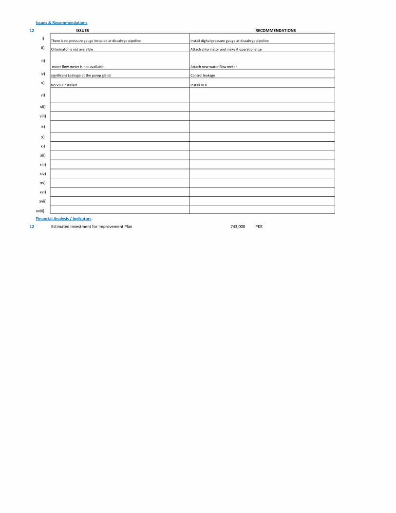
Issues & Recommendations
12 ISSUES RECOMMENDATIONS
i)
ii)
iii)
iv)
v)
vi)
vii)
viii)
ix)
x)
xi)
xii)
xiii)
xiv)
xv)
xvi)
xvii)
xviii)
Financial Analysis / Indicators
12 Estimated Investment for Improvement Plan 743,000 PKR
Install VFDNo VFD installed
Control leakagesignificant Leakage at the pump gland
Chlorinator is not avaialble Attach chlorinator and make it operationalize
water flow meter is not available Attach new water flow meter
There is no pressure gauge installed at discahrge pipeline Install digital pressure gauge at discahrge pipeline
1 Pumping Station Information
1 Fresh Water Supply
2 Wastewater Disposal
3 Waste Water Treatment Plant
4 Water Treatment Plant
Name of Engineer
WASA Staff Name
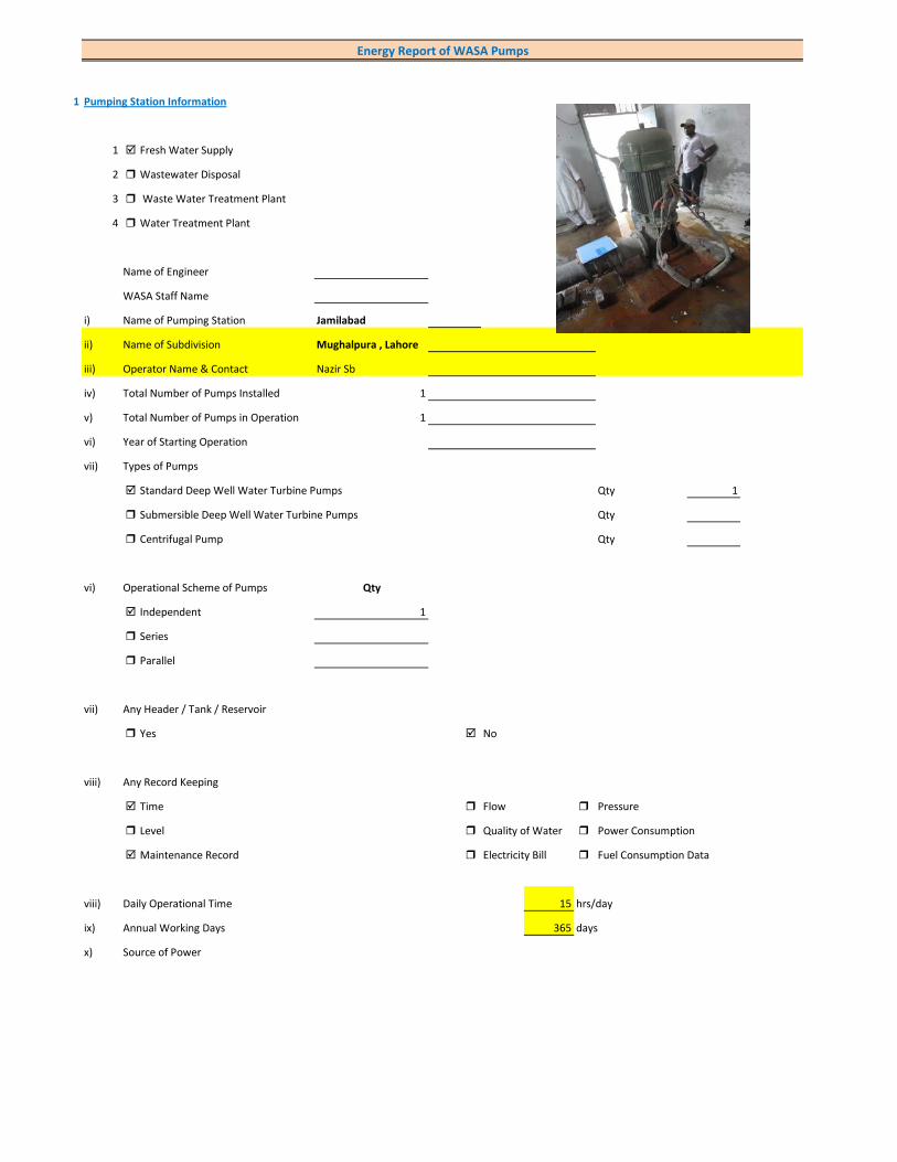
i) Name of Pumping Station Jamilabad
ii) Name of Subdivision Mughalpura , Lahore
iii) Operator Name & Contact Nazir Sb
iv) Total Number of Pumps Installed 1
v) Total Number of Pumps in Operation 1
vi) Year of Starting Operation
vii) Types of Pumps
Standard Deep Well Water Turbine Pumps Qty 1
Submersible Deep Well Water Turbine Pumps Qty
Centrifugal Pump Qty
vi) Operational Scheme of Pumps Qty
Independent 1
Series
Parallel
vii) Any Header / Tank / Reservoir
Yes No
viii) Any Record Keeping
Time Flow Pressure
Level Quality of Water Power Consumption
Maintenance Record Electricity Bill Fuel Consumption Data
viii) Daily Operational Time 15 hrs/day
ix) Annual Working Days 365 days
x) Source of Power
Energy Report of WASA Pumps

Primary LESCO Secondary
xi) In Case of Secondary Power Source Fuel Data Details
xii) Operational Hours of Secondary Power Source hrs/day
xiii) Availability of Chlorinator
Yes No
2 Pump Basic Information (Pump Ref # CITY_FWPS/WWDS_Pump #)
i) Type of Pump Deep Well
Submersible
Overhung
Between Bearing
ii) Mounting / Erection
Horizontal Vertical
Foundation
iii) Concrete Bolted Bolted
iv) Lubrication Type
Oil Water
v) Cooling Type
Water Cooled Air Cooled
vi) Number of Stages
Single Multi 5
vii) Pump and Motor Assembly
Direct Coupled Belt / Gear
viii) Source of Suction
Ground Water Aquafier Overhead Tank Underground Tank
Pressurized Source
ix) Pump Discharge Destination
Overhead Tank Drain On Ground Reservoir
Fresh Water Supply Network
Pump Operational Scheme
On / OFF Proportional
x) Pump Flow Control
Throttle VFD Controlled
xi) Any Retrofits ?
Impeller Detail
Casing / Volute Detail
Line Shaft (DW) Detail
Column Sett. (DW) Detail

Motor Replacement Detail
Motor Rewinding Detail
xii) Self Priming
Yes No NA (not applicable)
xiii) Non Clogging (In case of wastewater)
Yes No
xiv) Flowmeter Available
Yes No
xv) Flowmeter Working
Working Properly Malfunctioning (Damaged)
3 Pump Nameplate Data
i) Make / Brand Country
ii) Model Serial
iii) Certification Mark
iv) Year of Manufacture
v) Flowrate (Q) 2 Cusec 204 m3/hr
vi) Head (H) ft
vii) Discharge Pressure (P) Psig
viii) Power / HP / BHP BHP
ix) Speed (n) RPM
x) Maximum Pressure (Pmax)
xi) Maxiumum Allowable Temperature
5 Piping System
Suction Side
Select Pipe Material of Construction MS Pipe
i) Enter Diameter of Suction Pipe (In) (Not Valid incase of Tubewells)
ii) Enter Length of Suction Pipe (ft) (Not Valid incase of Tubewells)
iii) Enter Fittings on Suction Pipe (Not Valid incase of Tubewells)
Fitting Type 1 Qty Type 2 Qty Type 3 Qty
Valves Foot Valve 1
Bends
Strainer 1
iv) Storage Capacity of Suction Source (Aquafier)
v) Working Volume of Source
vi) Suction Lift (from Datum Line)
viii) Availbility of Pressure Gauge Yes No
ix) Suction Pressure (Not Valid incase of Tubewells)

Discharge Side
Pipe Material of Construction MS Pipe
i) Diameter of Discharge Pipe 8 inch
ii) Length of Discharge Pipe (Not known as directly connected to network underground)
iii) Fittings on Discharge Pipe
Fitting Type 1 Qty Type 2 Qty Type 3 Qty
Valves Control 1 Check 1
Bends Elbow 1
Strainer
iv) Storage Capacity of Discharge Destination (Not known as directly connected to network underground))
v) Working Volume of Discharge Destination (Not known as directly connected to network underground))
vi) Discharge Elevation (from Datum Line) (In case of no gauge)
vii) Availbility of Pressure Gauge Yes No (Installed by Team)
viii) Discharge Pressure 13 psig
6 Motor Nameplate Data
i) Manufacturer Siemens
ii) Rated kW / hp 80 hp 60 kW
iii) Voltage Range (Volts) 380 Volts
iv) Current (Ampere) 115
v) Power Factor (Cos ɸ) 0.85
Efficiency Class
IE3 Eff 1
IE2 Eff 2
IE1 Eff 3
Standard Efficiency
vi) Motor Speed 1,488 RPM
vii) Reference Frequency 50 C/S
viii) Insulation Class F
ix) Motor Frame Size 250 M
x)
7 Electrical System Observations
i) Electrical Meter Reference Number
ii) Meter Reading
iii) Meter Time and Date
Correct FALSE
Lag by Lead by
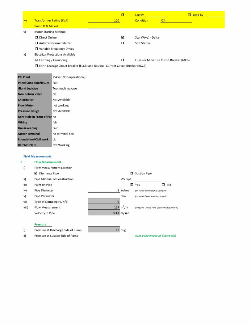
iv) Transformer Rating (kVA) 100 Condition OK
Pump O & M Cost
v) Motor Starting Method
Direct Online Star (Wye) - Delta
Autotransformer Starter Soft Starter
Variable Frequency Drives
v) Electrical Protections Available
Earthing / Grounding Fuses or Miniature Circuit Breaker (MCB)
Earth Leakage Circuit Breaker (ELCB) and Residual Current Circuit Breaker (RCCB)
PFI Plant 25kvar(Non-operational)
Panel Condition/Issues Fair
Gland Leakage Too much leakage
Non Return Valve ok
Chlorinator Not Available
Flow Meter not working
Pressure Gauge Not Available
Bore Hole in Front of Panno
Wiring fair
Housekeeping Fair
Motor Terminal no terminal box
Foundation/Civil work ok
Ratchet Plate Not Working
Field Measurements
8 Flow Measurement
i) Flow Measurement Location
Discharge Pipe Suction Pipe
ii) Pipe Material of Construction MS Pipe
iii) Paint on Pipe Yes No
iv) Pipe Diameter 8 inches (on which flowmeter is clamped)
v) Pipe Perimeter mm (on which flowmeter is clamped)
vi) Type of Clamping (V/N/Z) V
viii) Flow Measurement 167 m3/hr (Through Transit Time Ultrasonic Flowmeter)
Velocity in Pipe 1.43 m/sec
Pressure
i) Pressure at Discharge Side of Pump 13 psig
ii) Pressure at Suction Side of Pump (Not Valid incase of Tubewells)

iii) Water Shutoff Head
Levels
i) Static Water Level 38 meter Estimated
ii) Pumping Water Level 43 meter (estimated due to gland leakage and catching of wire by suction)
Electric Measurements
i) Voltage 414 410.3 409.2
ii) Ampere 87 80 84
iii) Power Factor 0.8
iv) Appearant Power (kVA) 59.5
v) Running Power (kW) 47.6
vi) Reactive Power (kVAr) 35.7
vi) Motor Working on Loading Basis 79.4 %
Oversize Undersize Properly Sized
Speed
i) Speed of Motor 1,488 RPM
ii) Speed of Pump Impeller RPM
Noise Level
Noise Level (db(A)) Avg. Max: 89
Thermal Imaging
i) Motor Motor Pump Coupling
Pump Volute Casing Pump Bearings
Electric Panels
Calculations
10
i) Drawdown of Pump (Pumping water level - Static Water Level) 16.4 ft
ii) Static Suction Head (Only for WW Pump) ft
iii) Suction Side Frictional Head (Only for WW Pump) ft
iv) Dynamic Suction Head (ii+iii) (Only for WW Pump) ft
v) Discharge Head (Pressure Gauge) 30.03 ft
vi) Discharge Side Frictional Head 5.34 ft
vii) Dynamic Discharge Head (v+vi) 35.37 ft

viii) Total Dynamic Head of Pump (TDH) (vii + Pumping Water Level) 176.41 ft
ix) Specific Capacity of Pump (Water Turbine) gpm/ft of drawdown 44.84
x) Specific Speed of Pump
Ns = RPM x GPM0.5 / H0.75
impeller rpm necessary to produce 1gpm/ft head 0
500-10,000, standard, 2,000-3,000 high efficiency
xi) Difference of Pump Curve flow and Measured Flow at the TDH m3/hr
xii) Deviation of actual flow from the pump curve flow %
xiii) Water Horsepower (whp) (TDH x Actual Measured Flow) 32.76 hp
xiv) Brake Horsepower (bhp) (OEM Data) 0 hp
xv) Electrical Horsepower(ehp) (Electrical Measurement at Motor input) 63.81 hp
xvi) Efficiency of Individual Pump (ηpump) (whp/bhp) x 100 #DIV/0! %
xvii) Efficiency of Pumping System (ηsystem)Existing (whp/ehp) x 100 51.34 %
xviii) Existing Specific Pumping Energy (En(pumping01)) 0.29 kWh/m3
xix) Avg. Cost of Energy (Based on Grid and Backup) 13 PKR/kWh
xx) Daily Operational Time of Pump 15 hrs
xxi) Daily Pump flow 2,505 m3/day
xxii) Annual working days 365 days
xxiii) Annual Pump flow 914,325 m3/yr
xxiv) Annual Energy Consumption of Pump (En(pumping01) x Annual Pump Flow) 262,007 kWh/yr
xxv) Annual Energy Expenditure on Pumping 3,406,096 PKR/Yr
xxvi) Pumping System Efficiency after Improvement 62 %
xxvii) Water Flow after Efficiency Improvement 202 m3/hr
xxviii) Specific Energy Consumption at New Efficiency 0.24 kWh/m3
xxix) Potential of Energy Reduction 17.20 %
xxx) Reduced Annual Energy Consumption at Improved Efficiency 45,061 kWh/yr
xxxi) Annual Financial Saving on Pumping 585,793 PKR/Yr
11 Summary of Findings
Pumping system efficiency is 51.34%. For pump attached with 80 HP motor, efficiency below 56% is considered to be LOW (> 65.9 is
excellent). This pumping system requires impeller adjustment. It is estimated that this impeller adjustment would increase pumping efficiency from 51.34% to 62% which is in the range of GOOD efficiency. This efficiency improvement will save about Rs. 585,793 per year.
Issues & Recommendations
12 ISSUES RECOMMENDATIONS
i)
ii)
iii)
iv)
v)
vi)
vii)
viii)
ix)
x)
xi)
xii)
xiii)
xiv)
xv)
xvi)
xvii)
xviii)
Financial Analysis / Indicators
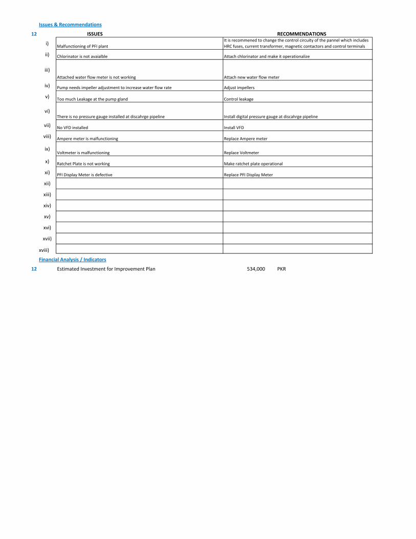
12 Estimated Investment for Improvement Plan 534,000 PKR
Control leakageToo much Leakage at the pump gland
Adjust impellersPump needs impeller adjustment to increase water flow rate
Chlorinator is not avaialble Attach chlorinator and make it operationalize
Attached water flow meter is not working Attach new water flow meter
Malfunctioning of PFI plantIt is recommened to change the control circuity of the pannel which includes HRC fuses, current transformer, magnetic contactors and control terminals
Replace Ampere meterAmpere meter is malfunctioning
Install digital pressure gauge at discahrge pipelineThere is no pressure gauge installed at discahrge pipeline
Ratchet Plate is not working Make ratchet plate operational
No VFD installed Install VFD
PFI Display Meter is defective Replace PFI Display Meter
Voltmeter is malfunctioning Replace Voltmeter
1 Pumping Station Information
1 Fresh Water Supply
2 Wastewater Disposal
3 Waste Water Treatment Plant
4 Water Treatment Plant
Name of Engineer
WASA Staff Name
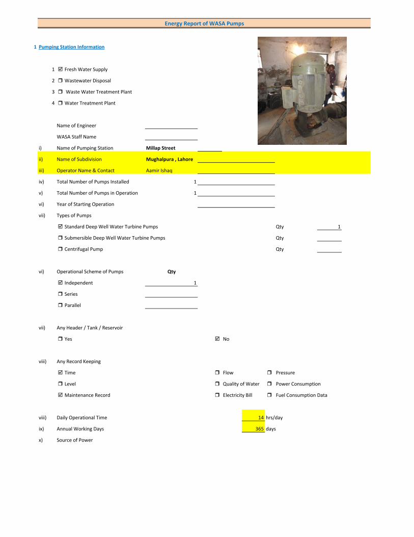
i) Name of Pumping Station Millap Street
ii) Name of Subdivision Mughalpura , Lahore
iii) Operator Name & Contact Aamir Ishaq
iv) Total Number of Pumps Installed 1
v) Total Number of Pumps in Operation 1
vi) Year of Starting Operation
vii) Types of Pumps
Standard Deep Well Water Turbine Pumps Qty 1
Submersible Deep Well Water Turbine Pumps Qty
Centrifugal Pump Qty
vi) Operational Scheme of Pumps Qty
Independent 1
Series
Parallel
vii) Any Header / Tank / Reservoir
Yes No
viii) Any Record Keeping
Time Flow Pressure
Level Quality of Water Power Consumption
Maintenance Record Electricity Bill Fuel Consumption Data
viii) Daily Operational Time 14 hrs/day
ix) Annual Working Days 365 days
x) Source of Power
Energy Report of WASA Pumps

Primary LESCO Secondary
xi) In Case of Secondary Power Source Fuel Data Details
xii) Operational Hours of Secondary Power Source hrs/day
xiii) Availability of Chlorinator
Yes No
2 Pump Basic Information (Pump Ref # CITY_FWPS/WWDS_Pump #)
i) Type of Pump Deep Well
Submersible
Overhung
Between Bearing
ii) Mounting / Erection
Horizontal Vertical
Foundation
iii) Concrete Bolted Bolted
iv) Lubrication Type
Oil Water
v) Cooling Type
Water Cooled Air Cooled
vi) Number of Stages
Single Multi 4
vii) Pump and Motor Assembly
Direct Coupled Belt / Gear
viii) Source of Suction
Ground Water Aquafier Overhead Tank Underground Tank
Pressurized Source
ix) Pump Discharge Destination
Overhead Tank Drain On Ground Reservoir
Fresh Water Supply Network
Pump Operational Scheme
On / OFF Proportional
x) Pump Flow Control
Throttle VFD Controlled
xi) Any Retrofits ?
Impeller Detail
Casing / Volute Detail
Line Shaft (DW) Detail
Column Sett. (DW) Detail

Motor Replacement Detail
Motor Rewinding Detail
xii) Self Priming
Yes No NA (not applicable)
xiii) Non Clogging (In case of wastewater)
Yes No
xiv) Flowmeter Available
Yes No
xv) Flowmeter Working
Working Properly Malfunctioning (Damaged)
3 Pump Nameplate Data
i) Make / Brand Country
ii) Model Serial
iii) Certification Mark
iv) Year of Manufacture
v) Flowrate (Q) 4 Cusec 408 m3/hr
vi) Head (H) ft
vii) Discharge Pressure (P) Psig
viii) Power / HP / BHP BHP
ix) Speed (n) RPM
x) Maximum Pressure (Pmax)
xi) Maxiumum Allowable Temperature
5 Piping System
Suction Side
Select Pipe Material of Construction MS Pipe
i) Enter Diameter of Suction Pipe (In) (Not Valid incase of Tubewells)
ii) Enter Length of Suction Pipe (ft) (Not Valid incase of Tubewells)
iii) Enter Fittings on Suction Pipe (Not Valid incase of Tubewells)
Fitting Type 1 Qty Type 2 Qty Type 3 Qty
Valves Foot Valve 1
Bends
Strainer 1
iv) Storage Capacity of Suction Source (Aquafier)
v) Working Volume of Source
vi) Suction Lift (from Datum Line)
viii) Availbility of Pressure Gauge Yes No
ix) Suction Pressure (Not Valid incase of Tubewells)

Discharge Side
Pipe Material of Construction MS Pipe
i) Diameter of Discharge Pipe 10 inch
ii) Length of Discharge Pipe (Not known as directly connected to network underground)
iii) Fittings on Discharge Pipe
Fitting Type 1 Qty Type 2 Qty Type 3 Qty
Valves Control 1 Check 1
Bends Elbow 1
Strainer
iv) Storage Capacity of Discharge Destination (Not known as directly connected to network underground))
v) Working Volume of Discharge Destination (Not known as directly connected to network underground))
vi) Discharge Elevation (from Datum Line) (In case of no gauge)
vii) Availbility of Pressure Gauge Yes No (Installed by Team)
viii) Discharge Pressure psig
6 Motor Nameplate Data
i) Manufacturer Siemens
ii) Rated kW / hp 150 hp 112.5 kW
iii) Voltage Range (Volts) 380 Volts
iv) Current (Ampere) 214
v) Power Factor (Cos ɸ) 0.85
Efficiency Class
IE3 Eff 1
IE2 Eff 2
IE1 Eff 3
Standard Efficiency
vi) Motor Speed 1,488 RPM
vii) Reference Frequency 50 C/S
viii) Insulation Class F
ix) Motor Frame Size 315 M
x)
7 Electrical System Observations
i) Electrical Meter Reference Number
ii) Meter Reading
iii) Meter Time and Date
Correct FALSE
Lag by Lead by
iv) Transformer Rating (kVA) 200 Condition OK
Pump O & M Cost
v) Motor Starting Method
Direct Online Star (Wye) - Delta
Autotransformer Starter Soft Starter
Variable Frequency Drives
v) Electrical Protections Available
Earthing / Grounding Fuses or Miniature Circuit Breaker (MCB)
Earth Leakage Circuit Breaker (ELCB) and Residual Current Circuit Breaker (RCCB)
PFI Plant Not installed
Panel Condition/Issues very poor
Gland Leakage minor leakage
Non Return Valve not working
Chlorinator Not Available
Flow Meter Not Available
Pressure Gauge Not Available
Bore Hole in Front of Panno
Wiring poor
Housekeeping poor
Motor Terminal ok
Foundation/Civil work ok
Ratchet Plate Not Working
Field Measurements
8 Flow Measurement
i) Flow Measurement Location
Discharge Pipe Suction Pipe
ii) Pipe Material of Construction MS Pipe
iii) Paint on Pipe Yes No
iv) Pipe Diameter 10 inches (on which flowmeter is clamped)
v) Pipe Perimeter mm (on which flowmeter is clamped)
vi) Type of Clamping (V/N/Z) V
viii) Flow Measurement 210 m3/hr (Through Transit Time Ultrasonic Flowmeter) (Estimated)
Velocity in Pipe 1.15 m/sec
Pressure
i) Pressure at Discharge Side of Pump 8 psig (Estimated)
ii) Pressure at Suction Side of Pump (Not Valid incase of Tubewells)
iii) Water Shutoff Head
Levels
i) Static Water Level 38 meter Estimated
ii) Pumping Water Level 43 meter (estimated due to gland leakage and catching of wire by suction)
Electric Measurements
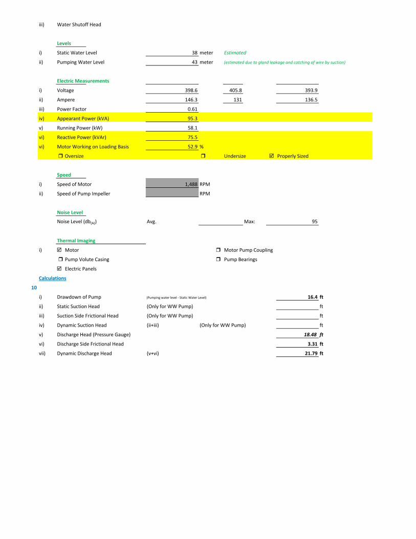
i) Voltage 398.6 405.8 393.9
ii) Ampere 146.3 131 136.5
iii) Power Factor 0.61
iv) Appearant Power (kVA) 95.3
v) Running Power (kW) 58.1
vi) Reactive Power (kVAr) 75.5
vi) Motor Working on Loading Basis 52.9 %
Oversize Undersize Properly Sized
Speed
i) Speed of Motor 1,488 RPM
ii) Speed of Pump Impeller RPM
Noise Level
Noise Level (db(A)) Avg. Max: 95
Thermal Imaging
i) Motor Motor Pump Coupling
Pump Volute Casing Pump Bearings
Electric Panels
Calculations
10
i) Drawdown of Pump (Pumping water level - Static Water Level) 16.4 ft
ii) Static Suction Head (Only for WW Pump) ft
iii) Suction Side Frictional Head (Only for WW Pump) ft
iv) Dynamic Suction Head (ii+iii) (Only for WW Pump) ft
v) Discharge Head (Pressure Gauge) 18.48 ft
vi) Discharge Side Frictional Head 3.31 ft
vii) Dynamic Discharge Head (v+vi) 21.79 ft
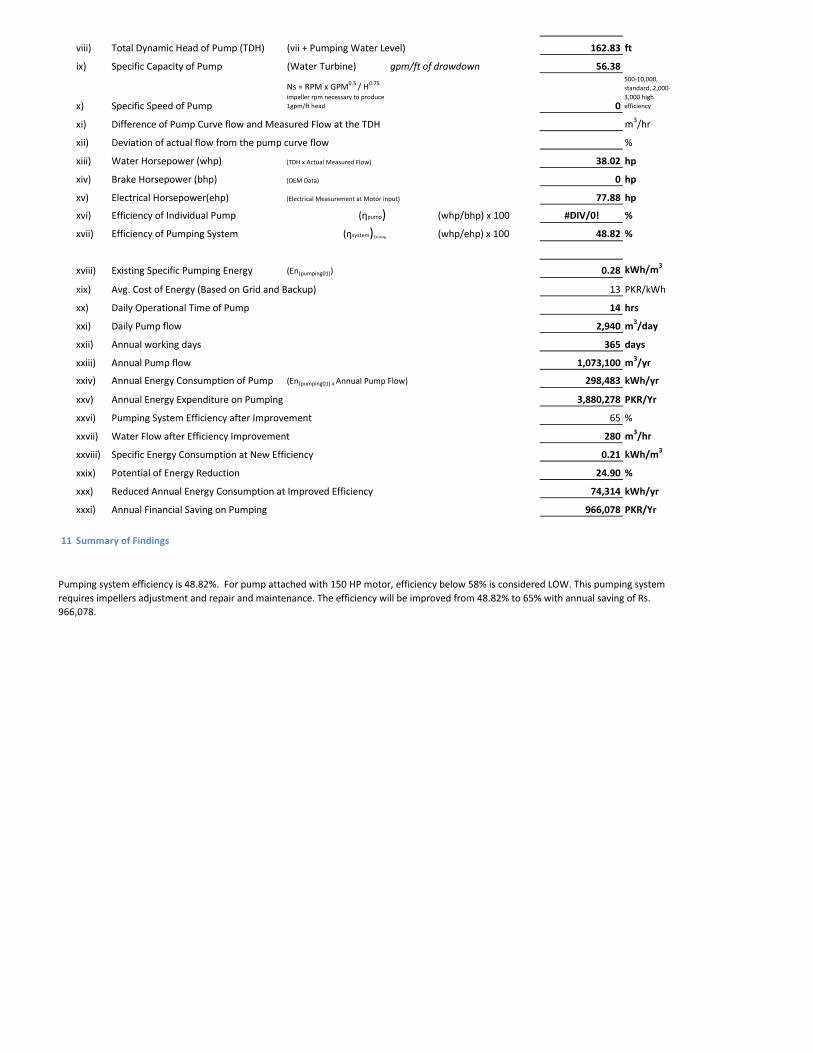
viii) Total Dynamic Head of Pump (TDH) (vii + Pumping Water Level) 162.83 ft
ix) Specific Capacity of Pump (Water Turbine) gpm/ft of drawdown 56.38
x) Specific Speed of Pump
Ns = RPM x GPM0.5 / H0.75
impeller rpm necessary to produce 1gpm/ft head 0
500-10,000, standard, 2,000-3,000 high efficiency
xi) Difference of Pump Curve flow and Measured Flow at the TDH m3/hr
xii) Deviation of actual flow from the pump curve flow %
xiii) Water Horsepower (whp) (TDH x Actual Measured Flow) 38.02 hp
xiv) Brake Horsepower (bhp) (OEM Data) 0 hp
xv) Electrical Horsepower(ehp) (Electrical Measurement at Motor input) 77.88 hp
xvi) Efficiency of Individual Pump (ηpump) (whp/bhp) x 100 #DIV/0! %
xvii) Efficiency of Pumping System (ηsystem)Existing (whp/ehp) x 100 48.82 %
xviii) Existing Specific Pumping Energy (En(pumping01)) 0.28 kWh/m3
xix) Avg. Cost of Energy (Based on Grid and Backup) 13 PKR/kWh
xx) Daily Operational Time of Pump 14 hrs
xxi) Daily Pump flow 2,940 m3/day
xxii) Annual working days 365 days
xxiii) Annual Pump flow 1,073,100 m3/yr
xxiv) Annual Energy Consumption of Pump (En(pumping01) x Annual Pump Flow) 298,483 kWh/yr
xxv) Annual Energy Expenditure on Pumping 3,880,278 PKR/Yr
xxvi) Pumping System Efficiency after Improvement 65 %
xxvii) Water Flow after Efficiency Improvement 280 m3/hr
xxviii) Specific Energy Consumption at New Efficiency 0.21 kWh/m3
xxix) Potential of Energy Reduction 24.90 %
xxx) Reduced Annual Energy Consumption at Improved Efficiency 74,314 kWh/yr
xxxi) Annual Financial Saving on Pumping 966,078 PKR/Yr
11 Summary of Findings
Pumping system efficiency is 48.82%. For pump attached with 150 HP motor, efficiency below 58% is considered LOW. This pumping system requires impellers adjustment and repair and maintenance. The efficiency will be improved from 48.82% to 65% with annual saving of Rs. 966,078.
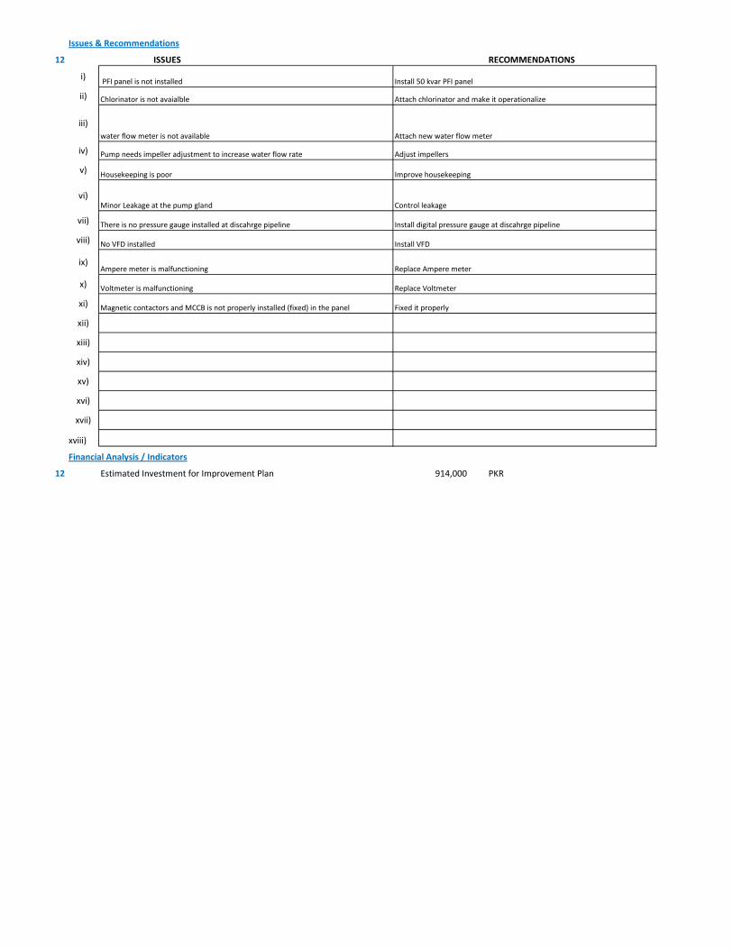
Issues & Recommendations
12 ISSUES RECOMMENDATIONS
i)
ii)
iii)
iv)
v)
vi)
vii)
viii)
ix)
x)
xi)
xii)
xiii)
xiv)
xv)
xvi)
xvii)
xviii)
Financial Analysis / Indicators
12 Estimated Investment for Improvement Plan 914,000 PKR
Improve housekeepingHousekeeping is poor
Adjust impellersPump needs impeller adjustment to increase water flow rate
Chlorinator is not avaialble Attach chlorinator and make it operationalize
water flow meter is not available Attach new water flow meter
PFI panel is not installed Install 50 kvar PFI panel
Control leakageMinor Leakage at the pump gland
Voltmeter is malfunctioning Replace Voltmeter
There is no pressure gauge installed at discahrge pipeline Install digital pressure gauge at discahrge pipeline
Magnetic contactors and MCCB is not properly installed (fixed) in the panel Fixed it properly
Ampere meter is malfunctioning Replace Ampere meter
No VFD installed Install VFD
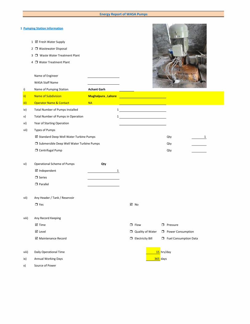
1 Pumping Station Information
1 Fresh Water Supply
2 Wastewater Disposal
3 Waste Water Treatment Plant
4 Water Treatment Plant
Name of Engineer
WASA Staff Name
i) Name of Pumping Station Achant Garh
ii) Name of Subdivision Mughalpura , Lahore
iii) Operator Name & Contact NA
iv) Total Number of Pumps Installed 1
v) Total Number of Pumps in Operation 1
vi) Year of Starting Operation
vii) Types of Pumps
Standard Deep Well Water Turbine Pumps Qty 1
Submersible Deep Well Water Turbine Pumps Qty
Centrifugal Pump Qty
vi) Operational Scheme of Pumps Qty
Independent 1
Series
Parallel
vii) Any Header / Tank / Reservoir
Yes No
viii) Any Record Keeping
Time Flow Pressure
Level Quality of Water Power Consumption
Maintenance Record Electricity Bill Fuel Consumption Data
viii) Daily Operational Time 15 hrs/day
ix) Annual Working Days 365 days
x) Source of Power
Energy Report of WASA Pumps

Primary LESCO Secondary
xi) In Case of Secondary Power Source Fuel Data Details
xii) Operational Hours of Secondary Power Source hrs/day
xiii) Availability of Chlorinator
Yes No
2 Pump Basic Information (Pump Ref # CITY_FWPS/WWDS_Pump #)
i) Type of Pump Deep Well
Submersible
Overhung
Between Bearing
ii) Mounting / Erection
Horizontal Vertical
Foundation
iii) Concrete Bolted Bolted
iv) Lubrication Type
Oil Water
v) Cooling Type
Water Cooled Air Cooled
vi) Number of Stages
Single Multi 5
vii) Pump and Motor Assembly
Direct Coupled Belt / Gear
viii) Source of Suction
Ground Water Aquafier Overhead Tank Underground Tank
Pressurized Source
ix) Pump Discharge Destination
Overhead Tank Drain On Ground Reservoir
Fresh Water Supply Network
Pump Operational Scheme
On / OFF Proportional
x) Pump Flow Control
Throttle VFD Controlled
xi) Any Retrofits ?
Impeller Detail
Casing / Volute Detail
Line Shaft (DW) Detail
Column Sett. (DW) Detail

Motor Replacement Detail
Motor Rewinding Detail
xii) Self Priming
Yes No NA (not applicable)
xiii) Non Clogging (In case of wastewater)
Yes No
xiv) Flowmeter Available
Yes No
xv) Flowmeter Working
Working Properly Malfunctioning (Damaged)
3 Pump Nameplate Data
i) Make / Brand KSB Pumps Country Pakistan
ii) Model B. 12 B/5 Serial 16-3264
iii) Certification Mark
iv) Year of Manufacture 2002
v) Flowrate (Q) 2 Cusec 204 m3/hr
vi) Head (H) 210 ft
vii) Discharge Pressure (P) Psig
viii) Power / HP / BHP 59.59 BHP
ix) Speed (n) 1,450 RPM
x) Maximum Pressure (Pmax)
xi) Maxiumum Allowable Temperature
5 Piping System
Suction Side
Select Pipe Material of Construction MS Pipe
i) Enter Diameter of Suction Pipe (In) (Not Valid incase of Tubewells)
ii) Enter Length of Suction Pipe (ft) (Not Valid incase of Tubewells)
iii) Enter Fittings on Suction Pipe (Not Valid incase of Tubewells)
Fitting Type 1 Qty Type 2 Qty Type 3 Qty
Valves Foot Valve 1
Bends
Strainer 1
iv) Storage Capacity of Suction Source (Aquafier)
v) Working Volume of Source
vi) Suction Lift (from Datum Line)
viii) Availbility of Pressure Gauge Yes No
ix) Suction Pressure (Not Valid incase of Tubewells)
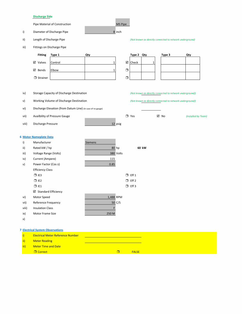
Discharge Side
Pipe Material of Construction MS Pipe
i) Diameter of Discharge Pipe 8 inch
ii) Length of Discharge Pipe (Not known as directly connected to network underground)
iii) Fittings on Discharge Pipe
Fitting Type 1 Qty Type 2 Qty Type 3 Qty
Valves Control 1 Check 1
Bends Elbow 1
Strainer
iv) Storage Capacity of Discharge Destination (Not known as directly connected to network underground))
v) Working Volume of Discharge Destination (Not known as directly connected to network underground))
vi) Discharge Elevation (from Datum Line) (In case of no gauge)
vii) Availbility of Pressure Gauge Yes No (Installed by Team)
viii) Discharge Pressure 12 psig
6 Motor Nameplate Data
i) Manufacturer Siemens
ii) Rated kW / hp 80 hp 60 kW
iii) Voltage Range (Volts) 380 Volts
iv) Current (Ampere) 115
v) Power Factor (Cos ɸ) 0.85
Efficiency Class
IE3 Eff 1
IE2 Eff 2
IE1 Eff 3
Standard Efficiency
vi) Motor Speed 1,488 RPM
vii) Reference Frequency 50 C/S
viii) Insulation Class F
ix) Motor Frame Size 250 M
x)
7 Electrical System Observations
i) Electrical Meter Reference Number
ii) Meter Reading
iii) Meter Time and Date
Correct FALSE
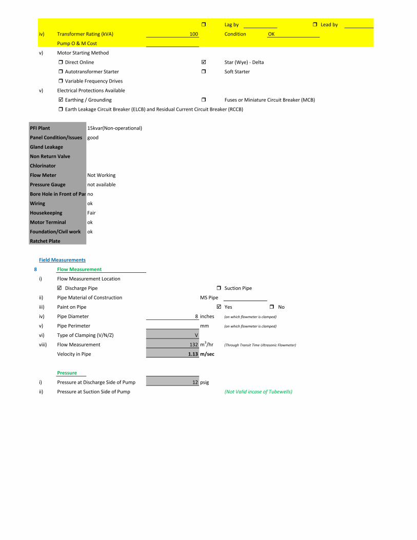
Lag by Lead by
iv) Transformer Rating (kVA) 100 Condition OK
Pump O & M Cost
v) Motor Starting Method
Direct Online Star (Wye) - Delta
Autotransformer Starter Soft Starter
Variable Frequency Drives
v) Electrical Protections Available
Earthing / Grounding Fuses or Miniature Circuit Breaker (MCB)
Earth Leakage Circuit Breaker (ELCB) and Residual Current Circuit Breaker (RCCB)
PFI Plant 15kvar(Non-operational)
Panel Condition/Issues good
Gland Leakage
Non Return Valve
Chlorinator
Flow Meter Not Working
Pressure Gauge not available
Bore Hole in Front of Panno
Wiring ok
Housekeeping Fair
Motor Terminal ok
Foundation/Civil work ok
Ratchet Plate
Field Measurements
8 Flow Measurement
i) Flow Measurement Location
Discharge Pipe Suction Pipe
ii) Pipe Material of Construction MS Pipe
iii) Paint on Pipe Yes No
iv) Pipe Diameter 8 inches (on which flowmeter is clamped)
v) Pipe Perimeter mm (on which flowmeter is clamped)
vi) Type of Clamping (V/N/Z) V
viii) Flow Measurement 132 m3/hr (Through Transit Time Ultrasonic Flowmeter)
Velocity in Pipe 1.13 m/sec
Pressure
i) Pressure at Discharge Side of Pump 12 psig
ii) Pressure at Suction Side of Pump (Not Valid incase of Tubewells)

iii) Water Shutoff Head
Levels
i) Static Water Level 38 meter Estimated
ii) Pumping Water Level 43 meter (estimated due to gland leakage and catching of wire by suction)
Electric Measurements
i) Voltage 411.5 406.1 411
ii) Ampere 76.8 77 77.1
iii) Power Factor 0.68
iv) Appearant Power (kVA) 54.5
v) Running Power (kW) 37.1
vi) Reactive Power (kVAr) 40
vi) Motor Working on Loading Basis 61.8 %
Oversize Undersize Properly Sized
Speed
i) Speed of Motor 1,485 RPM
ii) Speed of Pump Impeller 1,450 RPM
Noise Level
Noise Level (db(A)) Avg. Max:
Thermal Imaging
i) Motor Motor Pump Coupling
Pump Volute Casing Pump Bearings
Electric Panels
Calculations
10
i) Drawdown of Pump (Pumping water level - Static Water Level) 16.4 ft
ii) Static Suction Head (Only for WW Pump) ft
iii) Suction Side Frictional Head (Only for WW Pump) ft
iv) Dynamic Suction Head (ii+iii) (Only for WW Pump) ft
v) Discharge Head (Pressure Gauge) 27.72 ft
vi) Discharge Side Frictional Head 3.36 ft
vii) Dynamic Discharge Head (v+vi) 31.08 ft
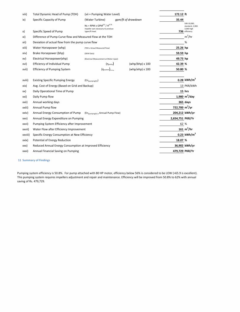
viii) Total Dynamic Head of Pump (TDH) (vii + Pumping Water Level) 172.12 ft
ix) Specific Capacity of Pump (Water Turbine) gpm/ft of drawdown 35.44
x) Specific Speed of Pump
Ns = RPM x GPM0.5 / H0.75
impeller rpm necessary to produce 1gpm/ft head 736
500-10,000, standard, 2,000-3,000 high efficiency
xi) Difference of Pump Curve flow and Measured Flow at the TDH m3/hr
xii) Deviation of actual flow from the pump curve flow %
xiii) Water Horsepower (whp) (TDH x Actual Measured Flow) 25.26 hp
xiv) Brake Horsepower (bhp) (OEM Data) 59.59 hp
xv) Electrical Horsepower(ehp) (Electrical Measurement at Motor input) 49.73 hp
xvi) Efficiency of Individual Pump (ηpump) (whp/bhp) x 100 42.39 %
xvii) Efficiency of Pumping System (ηsystem)Existing (whp/ehp) x 100 50.80 %
xviii) Existing Specific Pumping Energy (En(pumping01)) 0.28 kWh/m3
xix) Avg. Cost of Energy (Based on Grid and Backup) 13 PKR/kWh
xx) Daily Operational Time of Pump 15 hrs
xxi) Daily Pump flow 1,980 m3/day
xxii) Annual working days 365 days
xxiii) Annual Pump flow 722,700 m3/yr
xxiv) Annual Energy Consumption of Pump (En(pumping01) x Annual Pump Flow) 204,212 kWh/yr
xxv) Annual Energy Expenditure on Pumping 2,654,751 PKR/Yr
xxvi) Pumping System Efficiency after Improvement 62 %
xxvii) Water Flow after Efficiency Improvement 161 m3/hr
xxviii) Specific Energy Consumption at New Efficiency 0.23 kWh/m3
xxix) Potential of Energy Reduction 18.07 %
xxx) Reduced Annual Energy Consumption at Improved Efficiency 36,902 kWh/yr
xxxi) Annual Financial Saving on Pumping 479,729 PKR/Yr
11 Summary of Findings
Pumping system efficiency is 50.8%. For pump attached with 80 HP motor, efficiency below 56% is considered to be LOW (>65.9 is excellent). This pumping system requires impellers adjustment and repair and maintenance. Efficiency will be improved from 50.8% to 62% with annual saving of Rs. 479,729.
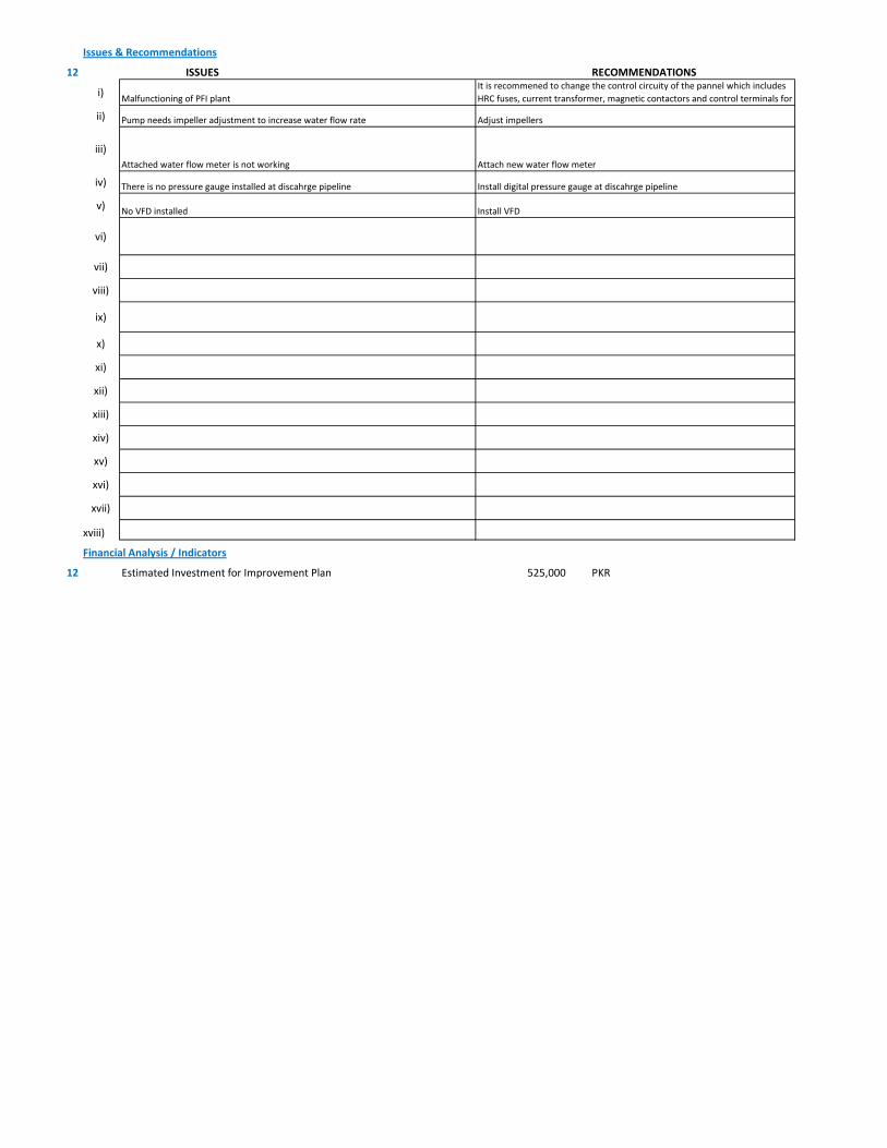
Issues & Recommendations
12 ISSUES RECOMMENDATIONS
i)
ii)
iii)
iv)
v)
vi)
vii)
viii)
ix)
x)
xi)
xii)
xiii)
xiv)
xv)
xvi)
xvii)
xviii)
Financial Analysis / Indicators
12 Estimated Investment for Improvement Plan 525,000 PKR
Install VFDNo VFD installed
Install digital pressure gauge at discahrge pipelineThere is no pressure gauge installed at discahrge pipeline
Pump needs impeller adjustment to increase water flow rate Adjust impellers
Attached water flow meter is not working Attach new water flow meter
Malfunctioning of PFI plantIt is recommened to change the control circuity of the pannel which includes HRC fuses, current transformer, magnetic contactors and control terminals for
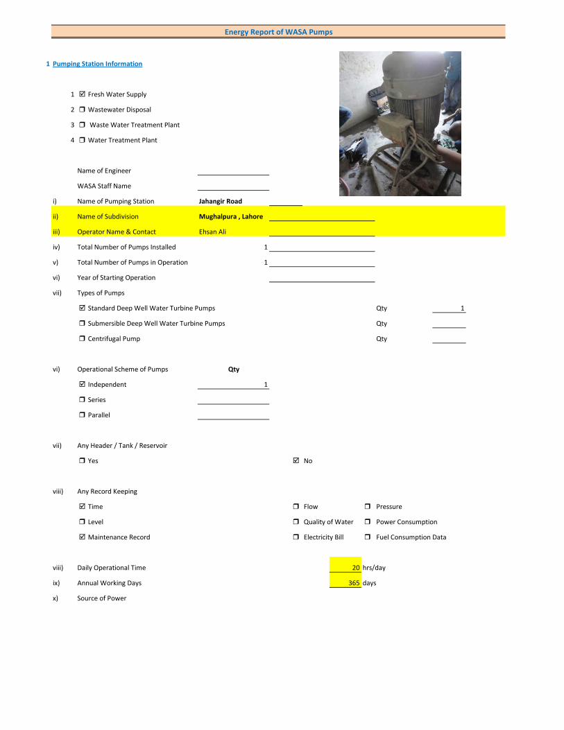
1 Pumping Station Information
1 Fresh Water Supply
2 Wastewater Disposal
3 Waste Water Treatment Plant
4 Water Treatment Plant
Name of Engineer
WASA Staff Name
i) Name of Pumping Station Jahangir Road
ii) Name of Subdivision Mughalpura , Lahore
iii) Operator Name & Contact Ehsan Ali
iv) Total Number of Pumps Installed 1
v) Total Number of Pumps in Operation 1
vi) Year of Starting Operation
vii) Types of Pumps
Standard Deep Well Water Turbine Pumps Qty 1
Submersible Deep Well Water Turbine Pumps Qty
Centrifugal Pump Qty
vi) Operational Scheme of Pumps Qty
Independent 1
Series
Parallel
vii) Any Header / Tank / Reservoir
Yes No
viii) Any Record Keeping
Time Flow Pressure
Level Quality of Water Power Consumption
Maintenance Record Electricity Bill Fuel Consumption Data
viii) Daily Operational Time 20 hrs/day
ix) Annual Working Days 365 days
x) Source of Power
Energy Report of WASA Pumps
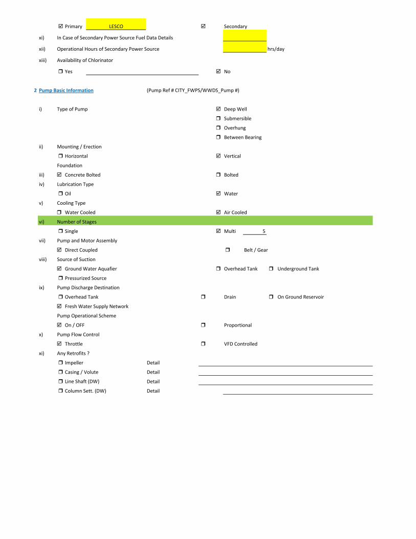
Primary LESCO Secondary
xi) In Case of Secondary Power Source Fuel Data Details
xii) Operational Hours of Secondary Power Source hrs/day
xiii) Availability of Chlorinator
Yes No
2 Pump Basic Information (Pump Ref # CITY_FWPS/WWDS_Pump #)
i) Type of Pump Deep Well
Submersible
Overhung
Between Bearing
ii) Mounting / Erection
Horizontal Vertical
Foundation
iii) Concrete Bolted Bolted
iv) Lubrication Type
Oil Water
v) Cooling Type
Water Cooled Air Cooled
vi) Number of Stages
Single Multi 5
vii) Pump and Motor Assembly
Direct Coupled Belt / Gear
viii) Source of Suction
Ground Water Aquafier Overhead Tank Underground Tank
Pressurized Source
ix) Pump Discharge Destination
Overhead Tank Drain On Ground Reservoir
Fresh Water Supply Network
Pump Operational Scheme
On / OFF Proportional
x) Pump Flow Control
Throttle VFD Controlled
xi) Any Retrofits ?
Impeller Detail
Casing / Volute Detail
Line Shaft (DW) Detail
Column Sett. (DW) Detail

Motor Replacement Detail
Motor Rewinding Detail
xii) Self Priming
Yes No NA (not applicable)
xiii) Non Clogging (In case of wastewater)
Yes No
xiv) Flowmeter Available
Yes No
xv) Flowmeter Working
Working Properly Malfunctioning (Damaged)
3 Pump Nameplate Data
i) Make / Brand KSB Pumps Country Pakistan
ii) Model B. 12 B/5 Serial 21-09-10-11331
iii) Certification Mark
iv) Year of Manufacture 2009
v) Flowrate (Q) 2 Cusec 204 m3/hr
vi) Head (H) 210 ft
vii) Discharge Pressure (P) Psig
viii) Power / HP / BHP 59.53 BHP
ix) Speed (n) 1,450 RPM
x) Maximum Pressure (Pmax)
xi) Maxiumum Allowable Temperature
5 Piping System
Suction Side
Select Pipe Material of Construction MS Pipe
i) Enter Diameter of Suction Pipe (In) (Not Valid incase of Tubewells)
ii) Enter Length of Suction Pipe (ft) (Not Valid incase of Tubewells)
iii) Enter Fittings on Suction Pipe (Not Valid incase of Tubewells)
Fitting Type 1 Qty Type 2 Qty Type 3 Qty
Valves Foot Valve 1
Bends
Strainer 1
iv) Storage Capacity of Suction Source (Aquafier)
v) Working Volume of Source
vi) Suction Lift (from Datum Line)
viii) Availbility of Pressure Gauge Yes No
ix) Suction Pressure (Not Valid incase of Tubewells)

Discharge Side
Pipe Material of Construction MS Pipe
i) Diameter of Discharge Pipe 8 inch
ii) Length of Discharge Pipe (Not known as directly connected to network underground)
iii) Fittings on Discharge Pipe
Fitting Type 1 Qty Type 2 Qty Type 3 Qty
Valves Control 1 Check 1
Bends Elbow 1
Strainer
iv) Storage Capacity of Discharge Destination (Not known as directly connected to network underground))
v) Working Volume of Discharge Destination (Not known as directly connected to network underground))
vi) Discharge Elevation (from Datum Line) (In case of no gauge)
vii) Availbility of Pressure Gauge Yes No (Installed by Team)
viii) Discharge Pressure 8 psig
6 Motor Nameplate Data
i) Manufacturer Siemens
ii) Rated kW / hp 80 hp 60 kW
iii) Voltage Range (Volts) 380 Volts
iv) Current (Ampere) 115
v) Power Factor (Cos ɸ) 0.85
Efficiency Class
IE3 Eff 1
IE2 Eff 2
IE1 Eff 3
Standard Efficiency
vi) Motor Speed 1,488 RPM
vii) Reference Frequency 50 C/S
viii) Insulation Class F
ix) Motor Frame Size 250 M
x)
7 Electrical System Observations
i) Electrical Meter Reference Number
ii) Meter Reading
iii) Meter Time and Date
Correct FALSE
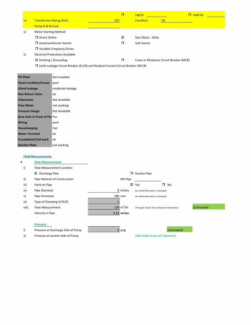
Lag by Lead by
iv) Transformer Rating (kVA) 100 Condition OK
Pump O & M Cost
v) Motor Starting Method
Direct Online Star (Wye) - Delta
Autotransformer Starter Soft Starter
Variable Frequency Drives
v) Electrical Protections Available
Earthing / Grounding Fuses or Miniature Circuit Breaker (MCB)
Earth Leakage Circuit Breaker (ELCB) and Residual Current Circuit Breaker (RCCB)
PFI Plant Not installed
Panel Condition/Issues poor
Gland Leakage moderate leakage
Non Return Valve ok
Chlorinator Not Available
Flow Meter not working
Pressure Gauge Not Available
Bore Hole in Front of PanYes
Wiring poor
Housekeeping Fair
Motor Terminal ok
Foundation/Civil work ok
Ratchet Plate not working
Field Measurements
8 Flow Measurement
i) Flow Measurement Location
Discharge Pipe Suction Pipe
ii) Pipe Material of Construction MS Pipe
iii) Paint on Pipe Yes No
iv) Pipe Diameter 8 inches (on which flowmeter is clamped)
v) Pipe Perimeter 780 mm (on which flowmeter is clamped)
vi) Type of Clamping (V/N/Z) V
viii) Flow Measurement 130 m3/hr (Through Transit Time Ultrasonic Flowmeter) (Estimated)
Velocity in Pipe 1.11 m/sec
Pressure
i) Pressure at Discharge Side of Pump 8 psig (Estimated)
ii) Pressure at Suction Side of Pump (Not Valid incase of Tubewells)
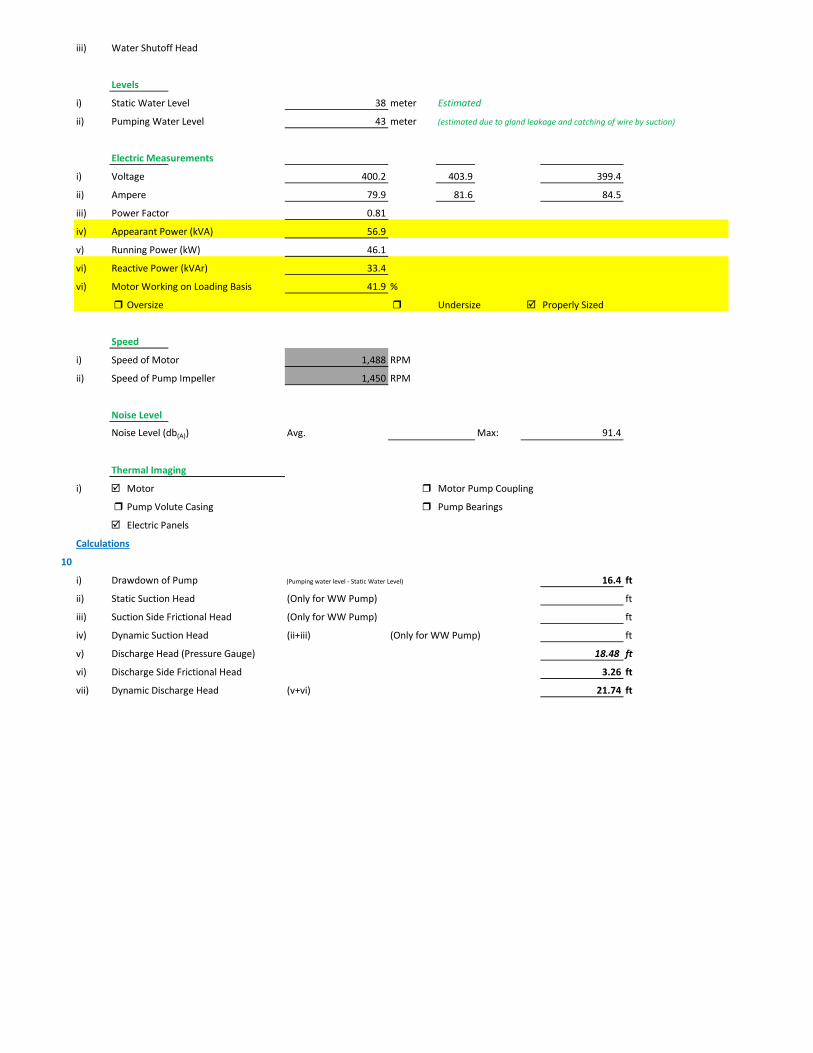
iii) Water Shutoff Head
Levels
i) Static Water Level 38 meter Estimated
ii) Pumping Water Level 43 meter (estimated due to gland leakage and catching of wire by suction)
Electric Measurements
i) Voltage 400.2 403.9 399.4
ii) Ampere 79.9 81.6 84.5
iii) Power Factor 0.81
iv) Appearant Power (kVA) 56.9
v) Running Power (kW) 46.1
vi) Reactive Power (kVAr) 33.4
vi) Motor Working on Loading Basis 41.9 %
Oversize Undersize Properly Sized
Speed
i) Speed of Motor 1,488 RPM
ii) Speed of Pump Impeller 1,450 RPM
Noise Level
Noise Level (db(A)) Avg. Max: 91.4
Thermal Imaging
i) Motor Motor Pump Coupling
Pump Volute Casing Pump Bearings
Electric Panels
Calculations
10
i) Drawdown of Pump (Pumping water level - Static Water Level) 16.4 ft
ii) Static Suction Head (Only for WW Pump) ft
iii) Suction Side Frictional Head (Only for WW Pump) ft
iv) Dynamic Suction Head (ii+iii) (Only for WW Pump) ft
v) Discharge Head (Pressure Gauge) 18.48 ft
vi) Discharge Side Frictional Head 3.26 ft
vii) Dynamic Discharge Head (v+vi) 21.74 ft

viii) Total Dynamic Head of Pump (TDH) (vii + Pumping Water Level) 162.78 ft
ix) Specific Capacity of Pump (Water Turbine) gpm/ft of drawdown 34.90
x) Specific Speed of Pump
Ns = RPM x GPM0.5 / H0.75
impeller rpm necessary to produce 1gpm/ft head 761
500-10,000, standard, 2,000-3,000 high efficiency
xi) Difference of Pump Curve flow and Measured Flow at the TDH m3/hr
xii) Deviation of actual flow from the pump curve flow %
xiii) Water Horsepower (whp) (TDH x Actual Measured Flow) 23.53 hp
xiv) Brake Horsepower (bhp) (OEM Data) 59.53 hp
xv) Electrical Horsepower(ehp) (Electrical Measurement at Motor input) 61.80 hp
xvi) Efficiency of Individual Pump (ηpump) (whp/bhp) x 100 39.52 %
xvii) Efficiency of Pumping System (ηsystem)Existing (whp/ehp) x 100 38.08 %
xviii) Existing Specific Pumping Energy (En(pumping01)) 0.36 kWh/m3
xix) Avg. Cost of Energy (Based on Grid and Backup) 13 PKR/kWh
xx) Daily Operational Time of Pump 20 hrs
xxi) Daily Pump flow 2,600 m3/day
xxii) Annual working days 365 days
xxiii) Annual Pump flow 949,000 m3/yr
xxiv) Annual Energy Consumption of Pump (En(pumping01) x Annual Pump Flow) 338,334 kWh/yr
xxv) Annual Energy Expenditure on Pumping 4,398,348 PKR/Yr
xxvi) Pumping System Efficiency after Improvement 62 %
xxvii) Water Flow after Efficiency Improvement 212 m3/hr
xxviii) Specific Energy Consumption at New Efficiency 0.22 kWh/m3
xxix) Potential of Energy Reduction 38.59 %
xxx) Reduced Annual Energy Consumption at Improved Efficiency 130,556 kWh/yr
xxxi) Annual Financial Saving on Pumping 1,697,232 PKR/Yr
11 Summary of Findings
Pumping system efficiency is 38.08%. For pump attached with 80 HP motor, efficiency below 56% is considered to be LOW (>65.9 is excellent). This pumping system requires impellers adjustment and repair and maintenance. Efficiency will be improved from 38.08% to 62% with annual saving of Rs. 1,697,232.
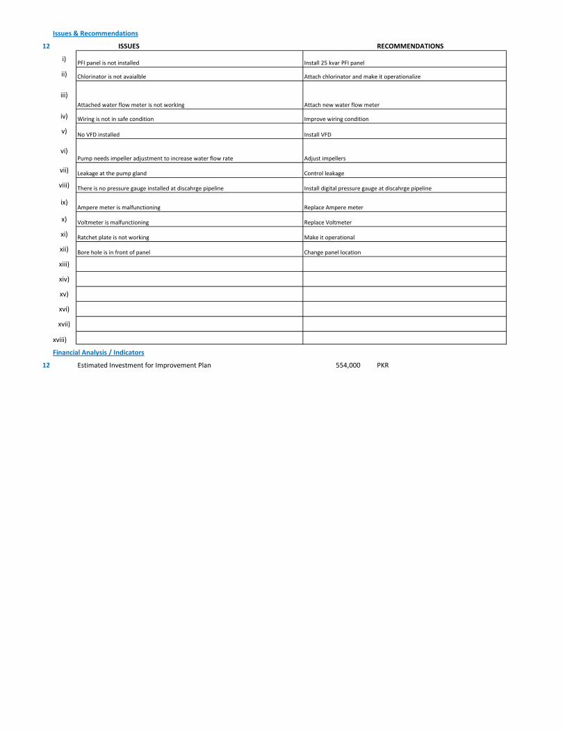
Issues & Recommendations
12 ISSUES RECOMMENDATIONS
i)
ii)
iii)
iv)
v)
vi)Pump needs impeller adjustment to increase water flow rate
vii)
viii)
ix)
x)
xi)
xii)
xiii)
xiv)
xv)
xvi)
xvii)
xviii)
Financial Analysis / Indicators
12 Estimated Investment for Improvement Plan 554,000 PKR
Bore hole is in front of panel Change panel location
Install digital pressure gauge at discahrge pipelineThere is no pressure gauge installed at discahrge pipeline
Adjust impellers
Voltmeter is malfunctioning Replace Voltmeter
Leakage at the pump gland Control leakage
Ratchet plate is not working Make it operational
Ampere meter is malfunctioning Replace Ampere meter
PFI panel is not installed Install 25 kvar PFI panel
Install VFDNo VFD installed
Improve wiring conditionWiring is not in safe condition
Chlorinator is not avaialble Attach chlorinator and make it operationalize
Attached water flow meter is not working Attach new water flow meter
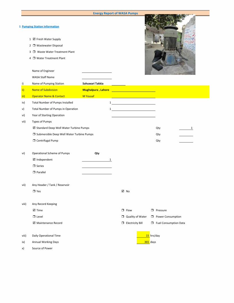
1 Pumping Station Information
1 Fresh Water Supply
2 Wastewater Disposal
3 Waste Water Treatment Plant
4 Water Treatment Plant
Name of Engineer
WASA Staff Name
i) Name of Pumping Station Sahuwari Takkia
ii) Name of Subdivision Mughalpura , Lahore
iii) Operator Name & Contact M Yousaf
iv) Total Number of Pumps Installed 1
v) Total Number of Pumps in Operation 1
vi) Year of Starting Operation
vii) Types of Pumps
Standard Deep Well Water Turbine Pumps Qty 1
Submersible Deep Well Water Turbine Pumps Qty
Centrifugal Pump Qty
vi) Operational Scheme of Pumps Qty
Independent 1
Series
Parallel
vii) Any Header / Tank / Reservoir
Yes No
viii) Any Record Keeping
Time Flow Pressure
Level Quality of Water Power Consumption
Maintenance Record Electricity Bill Fuel Consumption Data
viii) Daily Operational Time 15 hrs/day
ix) Annual Working Days 365 days
x) Source of Power
Energy Report of WASA Pumps

Primary LESCO Secondary
xi) In Case of Secondary Power Source Fuel Data Details
xii) Operational Hours of Secondary Power Source hrs/day
xiii) Availability of Chlorinator
Yes No
2 Pump Basic Information (Pump Ref # CITY_FWPS/WWDS_Pump #)
i) Type of Pump Deep Well
Submersible
Overhung
Between Bearing
ii) Mounting / Erection
Horizontal Vertical
Foundation
iii) Concrete Bolted Bolted
iv) Lubrication Type
Oil Water
v) Cooling Type
Water Cooled Air Cooled
vi) Number of Stages
Single Multi 2
vii) Pump and Motor Assembly
Direct Coupled Belt / Gear
viii) Source of Suction
Ground Water Aquafier Overhead Tank Underground Tank
Pressurized Source
ix) Pump Discharge Destination
Overhead Tank Drain On Ground Reservoir
Fresh Water Supply Network
Pump Operational Scheme
On / OFF Proportional
x) Pump Flow Control
Throttle VFD Controlled
xi) Any Retrofits ?
Impeller Detail
Casing / Volute Detail
Line Shaft (DW) Detail
Column Sett. (DW) Detail

Motor Replacement Detail
Motor Rewinding Detail
xii) Self Priming
Yes No NA (not applicable)
xiii) Non Clogging (In case of wastewater)
Yes No
xiv) Flowmeter Available
Yes No
xv) Flowmeter Working
Working Properly Malfunctioning (Damaged)
3 Pump Nameplate Data
i) Make / Brand KSB Pumps Country Pakistan
ii) Model B. 12 B/2 Serial 881-08-6656
iii) Certification Mark
iv) Year of Manufacture 1985
v) Flowrate (Q) 2.5 Cusec 255 m3/hr
vi) Head (H) 60 ft
vii) Discharge Pressure (P) Psig
viii) Power / HP / BHP 21.78 BHP
ix) Speed (n) 1,450 RPM
x) Maximum Pressure (Pmax)
xi) Maxiumum Allowable Temperature
5 Piping System
Suction Side
Select Pipe Material of Construction MS Pipe
i) Enter Diameter of Suction Pipe (In) (Not Valid incase of Tubewells)
ii) Enter Length of Suction Pipe (ft) (Not Valid incase of Tubewells)
iii) Enter Fittings on Suction Pipe (Not Valid incase of Tubewells)
Fitting Type 1 Qty Type 2 Qty Type 3 Qty
Valves Foot Valve 1
Bends
Strainer 1
iv) Storage Capacity of Suction Source (Aquafier)
v) Working Volume of Source
vi) Suction Lift (from Datum Line)
viii) Availbility of Pressure Gauge Yes No
ix) Suction Pressure (Not Valid incase of Tubewells)

Discharge Side
Pipe Material of Construction MS Pipe
i) Diameter of Discharge Pipe 8 inch
ii) Length of Discharge Pipe (Not known as directly connected to network underground)
iii) Fittings on Discharge Pipe
Fitting Type 1 Qty Type 2 Qty Type 3 Qty
Valves Control 1 Check 1
Bends Elbow 1
Strainer
iv) Storage Capacity of Discharge Destination (Not known as directly connected to network underground))
v) Working Volume of Discharge Destination (Not known as directly connected to network underground))
vi) Discharge Elevation (from Datum Line) (In case of no gauge)
vii) Availbility of Pressure Gauge Yes No (Installed by Team)
viii) Discharge Pressure 8 psig
6 Motor Nameplate Data
i) Manufacturer Siemens
ii) Rated kW / hp 80 hp 60 kW
iii) Voltage Range (Volts) 380 Volts
iv) Current (Ampere) 115
v) Power Factor (Cos ɸ) 0.85
Efficiency Class
IE3 Eff 1
IE2 Eff 2
IE1 Eff 3
Standard Efficiency
vi) Motor Speed 1,488 RPM
vii) Reference Frequency 50 C/S
viii) Insulation Class F
ix) Motor Frame Size 250 M
x)
7 Electrical System Observations
i) Electrical Meter Reference Number
ii) Meter Reading
iii) Meter Time and Date
Correct FALSE
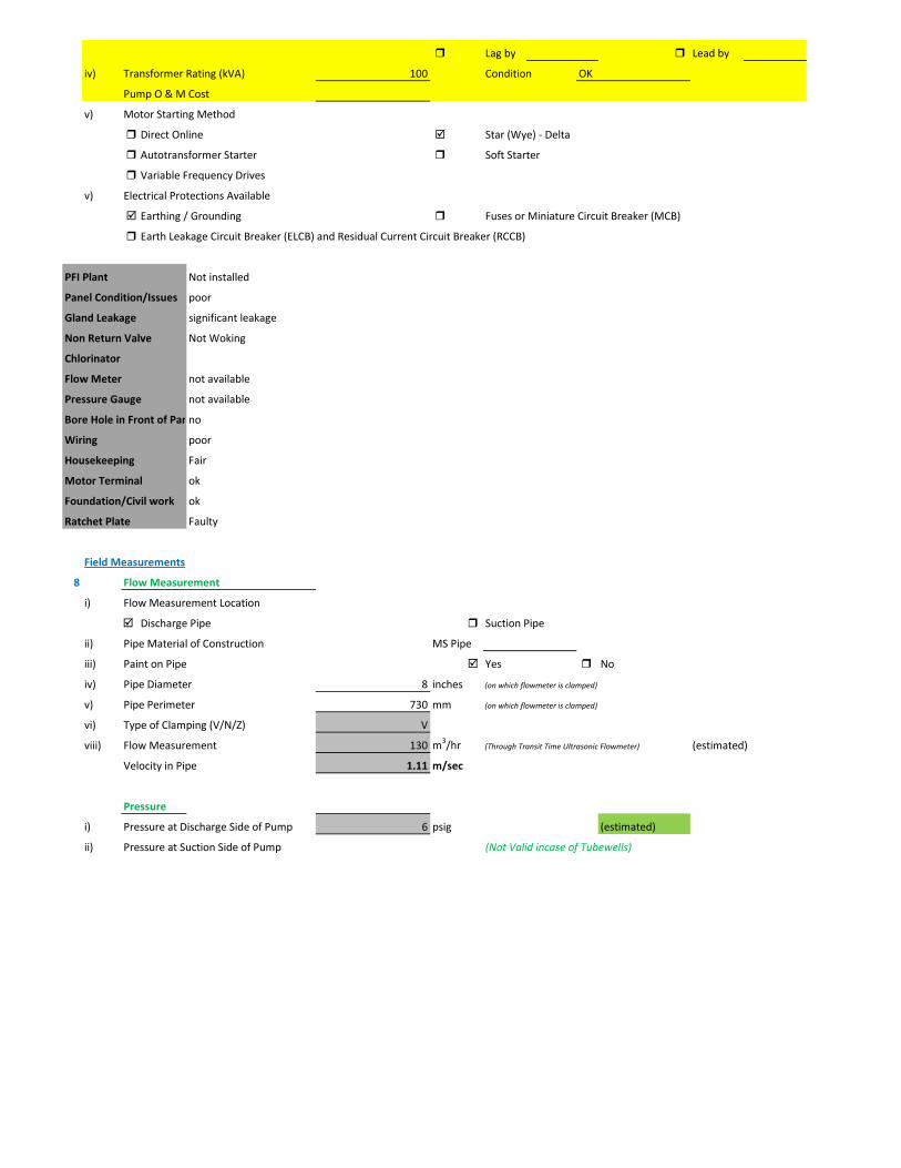
Lag by Lead by
iv) Transformer Rating (kVA) 100 Condition OK
Pump O & M Cost
v) Motor Starting Method
Direct Online Star (Wye) - Delta
Autotransformer Starter Soft Starter
Variable Frequency Drives
v) Electrical Protections Available
Earthing / Grounding Fuses or Miniature Circuit Breaker (MCB)
Earth Leakage Circuit Breaker (ELCB) and Residual Current Circuit Breaker (RCCB)
PFI Plant Not installed
Panel Condition/Issues poor
Gland Leakage significant leakage
Non Return Valve Not Woking
Chlorinator
Flow Meter not available
Pressure Gauge not available
Bore Hole in Front of Panno
Wiring poor
Housekeeping Fair
Motor Terminal ok
Foundation/Civil work ok
Ratchet Plate Faulty
Field Measurements
8 Flow Measurement
i) Flow Measurement Location
Discharge Pipe Suction Pipe
ii) Pipe Material of Construction MS Pipe
iii) Paint on Pipe Yes No
iv) Pipe Diameter 8 inches (on which flowmeter is clamped)
v) Pipe Perimeter 730 mm (on which flowmeter is clamped)
vi) Type of Clamping (V/N/Z) V
viii) Flow Measurement 130 m3/hr (Through Transit Time Ultrasonic Flowmeter) (estimated)
Velocity in Pipe 1.11 m/sec
Pressure
i) Pressure at Discharge Side of Pump 6 psig (estimated)
ii) Pressure at Suction Side of Pump (Not Valid incase of Tubewells)

iii) Water Shutoff Head
Levels
i) Static Water Level 38 meter Estimated
ii) Pumping Water Level 43 meter (estimated due to gland leakage and catching of wire by suction)
Electric Measurements
i) Voltage 377.5 379.2 383.7
ii) Ampere 70.2 74 78.2
iii) Power Factor 0.7
iv) Appearant Power (kVA) 48.8
v) Running Power (kW) 34.1
vi) Reactive Power (kVAr) 34.8
vi) Motor Working on Loading Basis 56.9 %
Oversize Undersize Properly Sized
Speed
i) Speed of Motor 1,491 RPM
ii) Speed of Pump Impeller 1,450 RPM
Noise Level
Noise Level (db(A)) Avg. Max: 91
Thermal Imaging
i) Motor Motor Pump Coupling
Pump Volute Casing Pump Bearings
Electric Panels
Calculations
10
i) Drawdown of Pump (Pumping water level - Static Water Level) 16.4 ft
ii) Static Suction Head (Only for WW Pump) ft
iii) Suction Side Frictional Head (Only for WW Pump) ft
iv) Dynamic Suction Head (ii+iii) (Only for WW Pump) ft
v) Discharge Head (Pressure Gauge) 13.86 ft
vi) Discharge Side Frictional Head 3.26 ft
vii) Dynamic Discharge Head (v+vi) 17.12 ft
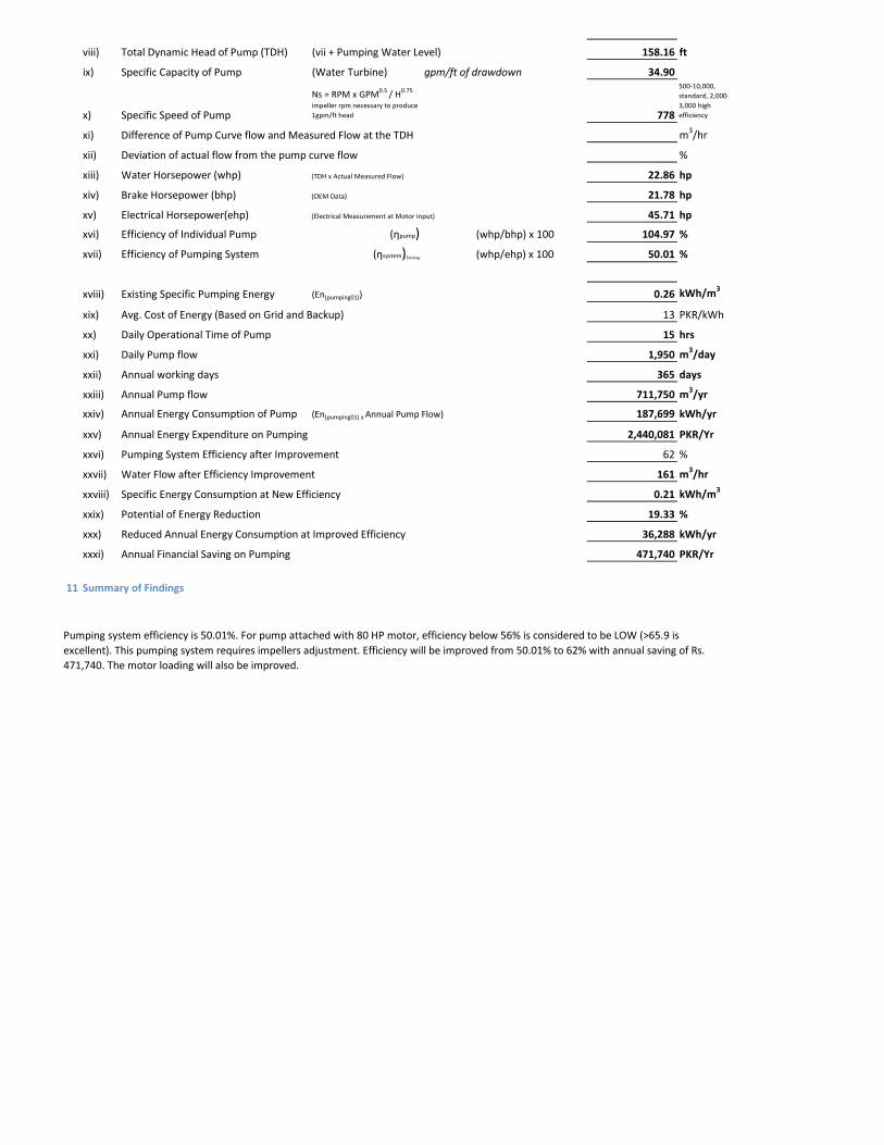
viii) Total Dynamic Head of Pump (TDH) (vii + Pumping Water Level) 158.16 ft
ix) Specific Capacity of Pump (Water Turbine) gpm/ft of drawdown 34.90
x) Specific Speed of Pump
Ns = RPM x GPM0.5 / H0.75
impeller rpm necessary to produce 1gpm/ft head 778
500-10,000, standard, 2,000-3,000 high efficiency
xi) Difference of Pump Curve flow and Measured Flow at the TDH m3/hr
xii) Deviation of actual flow from the pump curve flow %
xiii) Water Horsepower (whp) (TDH x Actual Measured Flow) 22.86 hp
xiv) Brake Horsepower (bhp) (OEM Data) 21.78 hp
xv) Electrical Horsepower(ehp) (Electrical Measurement at Motor input) 45.71 hp
xvi) Efficiency of Individual Pump (ηpump) (whp/bhp) x 100 104.97 %
xvii) Efficiency of Pumping System (ηsystem)Existing (whp/ehp) x 100 50.01 %
xviii) Existing Specific Pumping Energy (En(pumping01)) 0.26 kWh/m3
xix) Avg. Cost of Energy (Based on Grid and Backup) 13 PKR/kWh
xx) Daily Operational Time of Pump 15 hrs
xxi) Daily Pump flow 1,950 m3/day
xxii) Annual working days 365 days
xxiii) Annual Pump flow 711,750 m3/yr
xxiv) Annual Energy Consumption of Pump (En(pumping01) x Annual Pump Flow) 187,699 kWh/yr
xxv) Annual Energy Expenditure on Pumping 2,440,081 PKR/Yr
xxvi) Pumping System Efficiency after Improvement 62 %
xxvii) Water Flow after Efficiency Improvement 161 m3/hr
xxviii) Specific Energy Consumption at New Efficiency 0.21 kWh/m3
xxix) Potential of Energy Reduction 19.33 %
xxx) Reduced Annual Energy Consumption at Improved Efficiency 36,288 kWh/yr
xxxi) Annual Financial Saving on Pumping 471,740 PKR/Yr
11 Summary of Findings
Pumping system efficiency is 50.01%. For pump attached with 80 HP motor, efficiency below 56% is considered to be LOW (>65.9 is excellent). This pumping system requires impellers adjustment. Efficiency will be improved from 50.01% to 62% with annual saving of Rs. 471,740. The motor loading will also be improved.
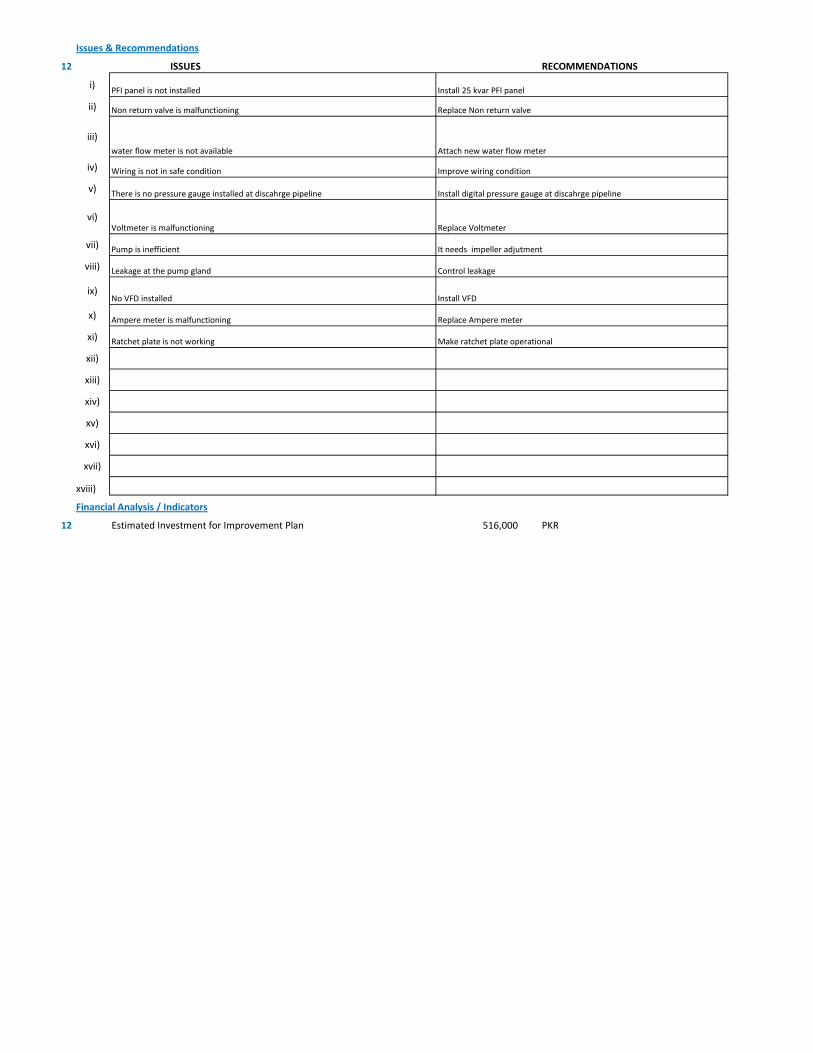
Issues & Recommendations
12 ISSUES RECOMMENDATIONS
i)
ii)
iii)
iv)
v)
vi)
vii)
viii)
ix)
x)
xi)
xii)
xiii)
xiv)
xv)
xvi)
xvii)
xviii)
Financial Analysis / Indicators
12 Estimated Investment for Improvement Plan 516,000 PKR
Control leakageLeakage at the pump gland
Replace Voltmeter Voltmeter is malfunctioning
Ampere meter is malfunctioning Replace Ampere meter
Pump is inefficient It needs impeller adjutment
Ratchet plate is not working Make ratchet plate operational
No VFD installed Install VFD
PFI panel is not installed Install 25 kvar PFI panel
Install digital pressure gauge at discahrge pipelineThere is no pressure gauge installed at discahrge pipeline
Improve wiring conditionWiring is not in safe condition
Non return valve is malfunctioning Replace Non return valve
water flow meter is not available Attach new water flow meter
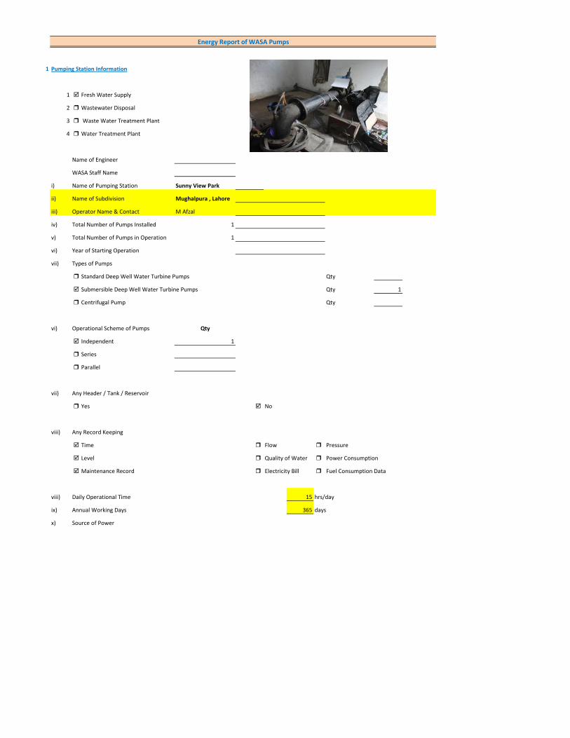
1 Pumping Station Information
1 Fresh Water Supply
2 Wastewater Disposal
3 Waste Water Treatment Plant
4 Water Treatment Plant
Name of Engineer
WASA Staff Name
i) Name of Pumping Station Sunny View Park
ii) Name of Subdivision Mughalpura , Lahore
iii) Operator Name & Contact M Afzal
iv) Total Number of Pumps Installed 1
v) Total Number of Pumps in Operation 1
vi) Year of Starting Operation
vii) Types of Pumps
Standard Deep Well Water Turbine Pumps Qty
Submersible Deep Well Water Turbine Pumps Qty 1
Centrifugal Pump Qty
vi) Operational Scheme of Pumps Qty
Independent 1
Series
Parallel
vii) Any Header / Tank / Reservoir
Yes No
viii) Any Record Keeping
Time Flow Pressure
Level Quality of Water Power Consumption
Maintenance Record Electricity Bill Fuel Consumption Data
viii) Daily Operational Time 15 hrs/day
ix) Annual Working Days 365 days
x) Source of Power
Energy Report of WASA Pumps
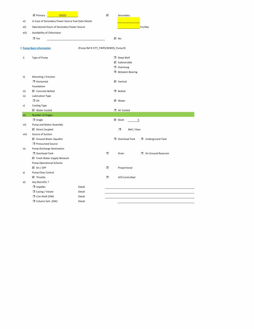
Primary LESCO Secondary
xi) In Case of Secondary Power Source Fuel Data Details
xii) Operational Hours of Secondary Power Source hrs/day
xiii) Availability of Chlorinator
Yes No
2 Pump Basic Information (Pump Ref # CITY_FWPS/WWDS_Pump #)
i) Type of Pump Deep Well
Submersible
Overhung
Between Bearing
ii) Mounting / Erection
Horizontal Vertical
Foundation
iii) Concrete Bolted Bolted
iv) Lubrication Type
Oil Water
v) Cooling Type
Water Cooled Air Cooled
vi) Number of Stages
Single Multi 5
vii) Pump and Motor Assembly
Direct Coupled Belt / Gear
viii) Source of Suction
Ground Water Aquafier Overhead Tank Underground Tank
Pressurized Source
ix) Pump Discharge Destination
Overhead Tank Drain On Ground Reservoir
Fresh Water Supply Network
Pump Operational Scheme
On / OFF Proportional
x) Pump Flow Control
Throttle VFD Controlled
xi) Any Retrofits ?
Impeller Detail
Casing / Volute Detail
Line Shaft (DW) Detail
Column Sett. (DW) Detail
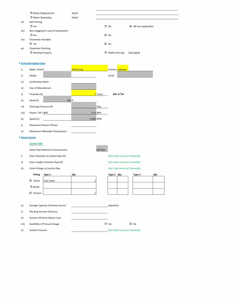
Motor Replacement Detail
Motor Rewinding Detail
xii) Self Priming
Yes No NA (not applicable)
xiii) Non Clogging (In case of wastewater)
Yes No
xiv) Flowmeter Available
Yes No
xv) Flowmeter Working
Working Properly Malfunctioning (Damaged)
3 Pump Nameplate Data
i) Make / Brand KSB Pumps Country Pakistan
ii) Model Serial
iii) Certification Mark
iv) Year of Manufacture
v) Flowrate (Q) 2 Cusec 204 m3/hr
vi) Head (H) 250 ft
vii) Discharge Pressure (P) Psig
viii) Power / HP / BHP 71.9 BHP
ix) Speed (n) 2,900 RPM
x) Maximum Pressure (Pmax)
xi) Maxiumum Allowable Temperature
5 Piping System
Suction Side
Select Pipe Material of Construction MS Pipe
i) Enter Diameter of Suction Pipe (In) (Not Valid incase of Tubewells)
ii) Enter Length of Suction Pipe (ft) (Not Valid incase of Tubewells)
iii) Enter Fittings on Suction Pipe (Not Valid incase of Tubewells)
Fitting Type 1 Qty Type 2 Qty Type 3 Qty
Valves Foot Valve 1
Bends
Strainer 1
iv) Storage Capacity of Suction Source (Aquafier)
v) Working Volume of Source
vi) Suction Lift (from Datum Line)
viii) Availbility of Pressure Gauge Yes No
ix) Suction Pressure (Not Valid incase of Tubewells)
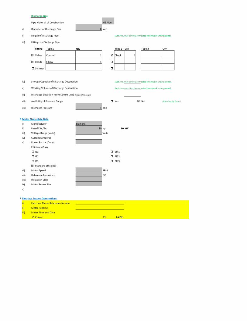
Discharge Side
Pipe Material of Construction MS Pipe
i) Diameter of Discharge Pipe 8 inch
ii) Length of Discharge Pipe (Not known as directly connected to network underground)
iii) Fittings on Discharge Pipe
Fitting Type 1 Qty Type 2 Qty Type 3 Qty
Valves Control 1 Check 1
Bends Elbow 1
Strainer
iv) Storage Capacity of Discharge Destination (Not known as directly connected to network underground))
v) Working Volume of Discharge Destination (Not known as directly connected to network underground))
vi) Discharge Elevation (from Datum Line) (In case of no gauge)
vii) Availbility of Pressure Gauge Yes No (Installed by Team)
viii) Discharge Pressure 4 psig
6 Motor Nameplate Data
i) Manufacturer Siemens
ii) Rated kW / hp 80 hp 60 kW
iii) Voltage Range (Volts) Volts
iv) Current (Ampere)
v) Power Factor (Cos ɸ)
Efficiency Class
IE3 Eff 1
IE2 Eff 2
IE1 Eff 3
Standard Efficiency
vi) Motor Speed RPM
vii) Reference Frequency C/S
viii) Insulation Class
ix) Motor Frame Size
x)
7 Electrical System Observations
i) Electrical Meter Reference Number
ii) Meter Reading
iii) Meter Time and Date
Correct FALSE
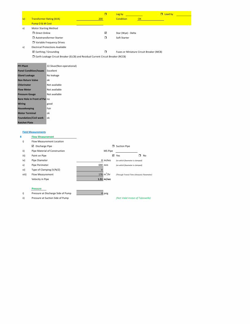
Lag by Lead by
iv) Transformer Rating (kVA) 200 Condition OK
Pump O & M Cost
v) Motor Starting Method
Direct Online Star (Wye) - Delta
Autotransformer Starter Soft Starter
Variable Frequency Drives
v) Electrical Protections Available
Earthing / Grounding Fuses or Miniature Circuit Breaker (MCB)
Earth Leakage Circuit Breaker (ELCB) and Residual Current Circuit Breaker (RCCB)
PFI Plant 22.5kvar(Non-operational)
Panel Condition/Issues Excellent
Gland Leakage No leakage
Non Return Valve ok
Chlorinator Not available
Flow Meter Not available
Pressure Gauge Not available
Bore Hole in Front of Panno
Wiring good
Housekeeping Fair
Motor Terminal ok
Foundation/Civil work ok
Ratchet Plate
Field Measurements
8 Flow Measurement
i) Flow Measurement Location
Discharge Pipe Suction Pipe
ii) Pipe Material of Construction MS Pipe
iii) Paint on Pipe Yes No
iv) Pipe Diameter 8 inches (on which flowmeter is clamped)
v) Pipe Perimeter 690 mm (on which flowmeter is clamped)
vi) Type of Clamping (V/N/Z) V
viii) Flow Measurement 176 m3/hr (Through Transit Time Ultrasonic Flowmeter)
Velocity in Pipe 1.51 m/sec
Pressure
i) Pressure at Discharge Side of Pump 4 psig
ii) Pressure at Suction Side of Pump (Not Valid incase of Tubewells)
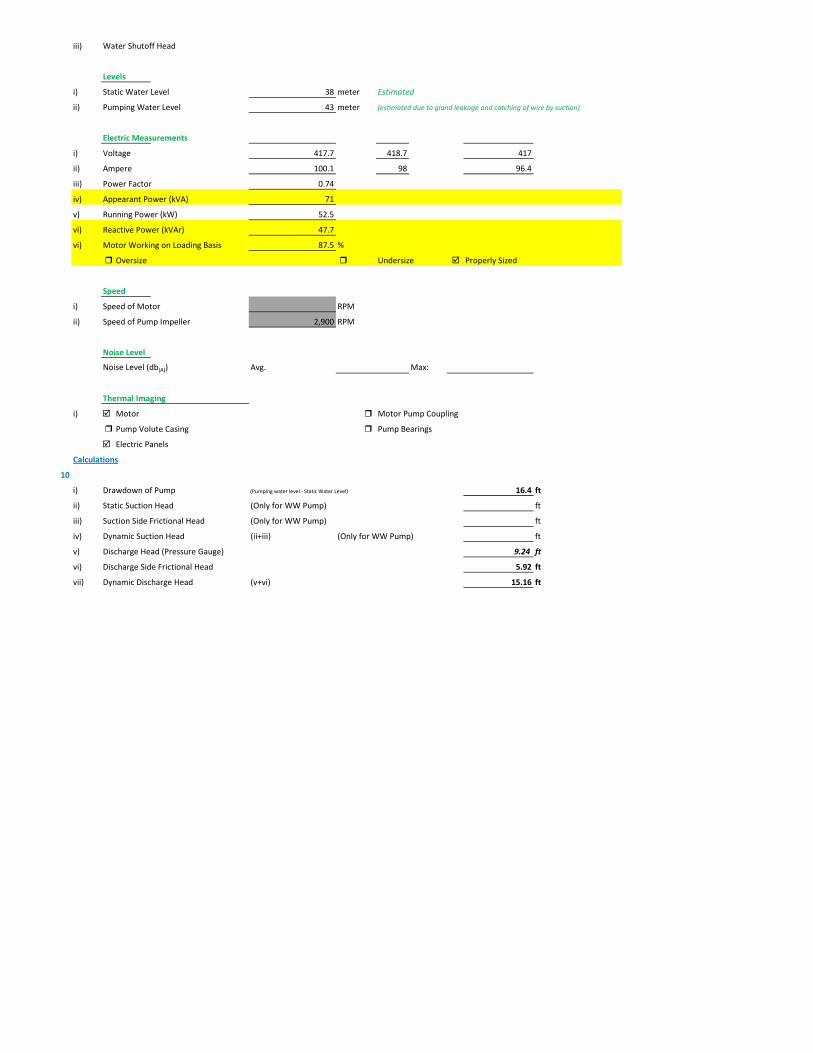
iii) Water Shutoff Head
Levels
i) Static Water Level 38 meter Estimated
ii) Pumping Water Level 43 meter (estimated due to gland leakage and catching of wire by suction)
Electric Measurements
i) Voltage 417.7 418.7 417
ii) Ampere 100.1 98 96.4
iii) Power Factor 0.74
iv) Appearant Power (kVA) 71
v) Running Power (kW) 52.5
vi) Reactive Power (kVAr) 47.7
vi) Motor Working on Loading Basis 87.5 %
Oversize Undersize Properly Sized
Speed
i) Speed of Motor RPM
ii) Speed of Pump Impeller 2,900 RPM
Noise Level
Noise Level (db(A)) Avg. Max:
Thermal Imaging
i) Motor Motor Pump Coupling
Pump Volute Casing Pump Bearings
Electric Panels
Calculations
10
i) Drawdown of Pump (Pumping water level - Static Water Level) 16.4 ft
ii) Static Suction Head (Only for WW Pump) ft
iii) Suction Side Frictional Head (Only for WW Pump) ft
iv) Dynamic Suction Head (ii+iii) (Only for WW Pump) ft
v) Discharge Head (Pressure Gauge) 9.24 ft
vi) Discharge Side Frictional Head 5.92 ft
vii) Dynamic Discharge Head (v+vi) 15.16 ft
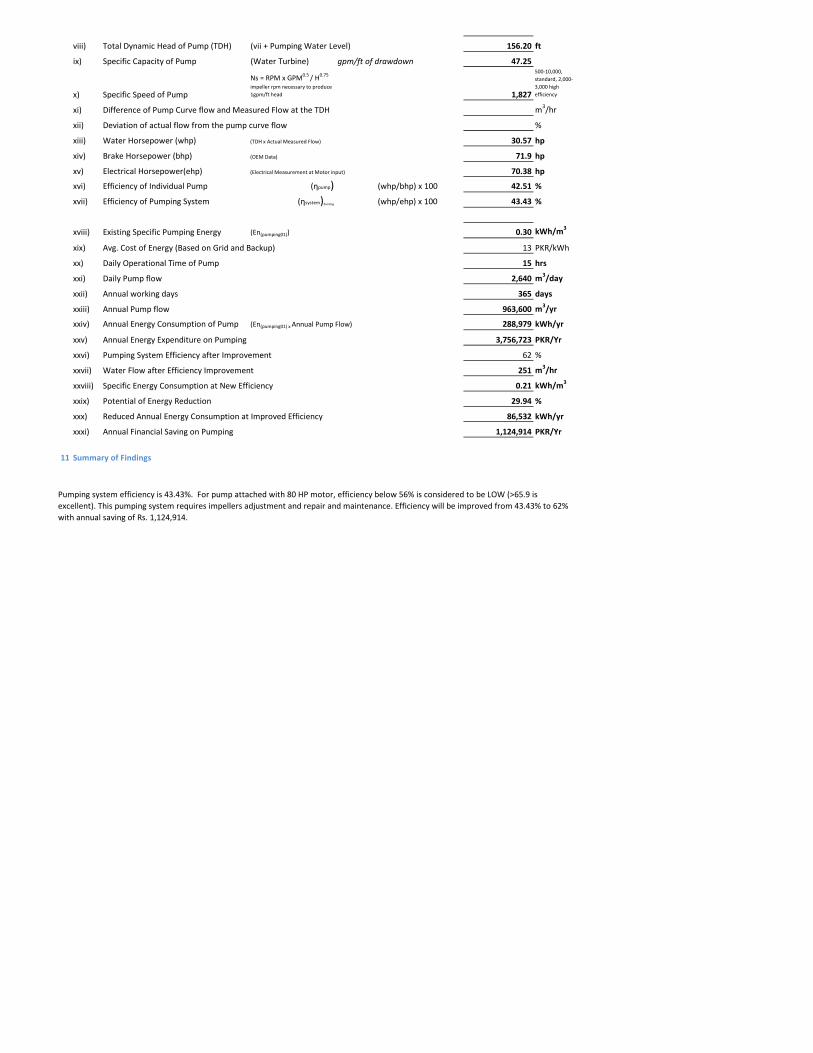
viii) Total Dynamic Head of Pump (TDH) (vii + Pumping Water Level) 156.20 ft
ix) Specific Capacity of Pump (Water Turbine) gpm/ft of drawdown 47.25
x) Specific Speed of Pump
Ns = RPM x GPM0.5 / H0.75
impeller rpm necessary to produce 1gpm/ft head 1,827
500-10,000, standard, 2,000-3,000 high efficiency
xi) Difference of Pump Curve flow and Measured Flow at the TDH m3/hr
xii) Deviation of actual flow from the pump curve flow %
xiii) Water Horsepower (whp) (TDH x Actual Measured Flow) 30.57 hp
xiv) Brake Horsepower (bhp) (OEM Data) 71.9 hp
xv) Electrical Horsepower(ehp) (Electrical Measurement at Motor input) 70.38 hp
xvi) Efficiency of Individual Pump (ηpump) (whp/bhp) x 100 42.51 %
xvii) Efficiency of Pumping System (ηsystem)Existing (whp/ehp) x 100 43.43 %
xviii) Existing Specific Pumping Energy (En(pumping01)) 0.30 kWh/m3
xix) Avg. Cost of Energy (Based on Grid and Backup) 13 PKR/kWh
xx) Daily Operational Time of Pump 15 hrs
xxi) Daily Pump flow 2,640 m3/day
xxii) Annual working days 365 days
xxiii) Annual Pump flow 963,600 m3/yr
xxiv) Annual Energy Consumption of Pump (En(pumping01) x Annual Pump Flow) 288,979 kWh/yr
xxv) Annual Energy Expenditure on Pumping 3,756,723 PKR/Yr
xxvi) Pumping System Efficiency after Improvement 62 %
xxvii) Water Flow after Efficiency Improvement 251 m3/hr
xxviii) Specific Energy Consumption at New Efficiency 0.21 kWh/m3
xxix) Potential of Energy Reduction 29.94 %
xxx) Reduced Annual Energy Consumption at Improved Efficiency 86,532 kWh/yr
xxxi) Annual Financial Saving on Pumping 1,124,914 PKR/Yr
11 Summary of Findings
Pumping system efficiency is 43.43%. For pump attached with 80 HP motor, efficiency below 56% is considered to be LOW (>65.9 is excellent). This pumping system requires impellers adjustment and repair and maintenance. Efficiency will be improved from 43.43% to 62% with annual saving of Rs. 1,124,914.
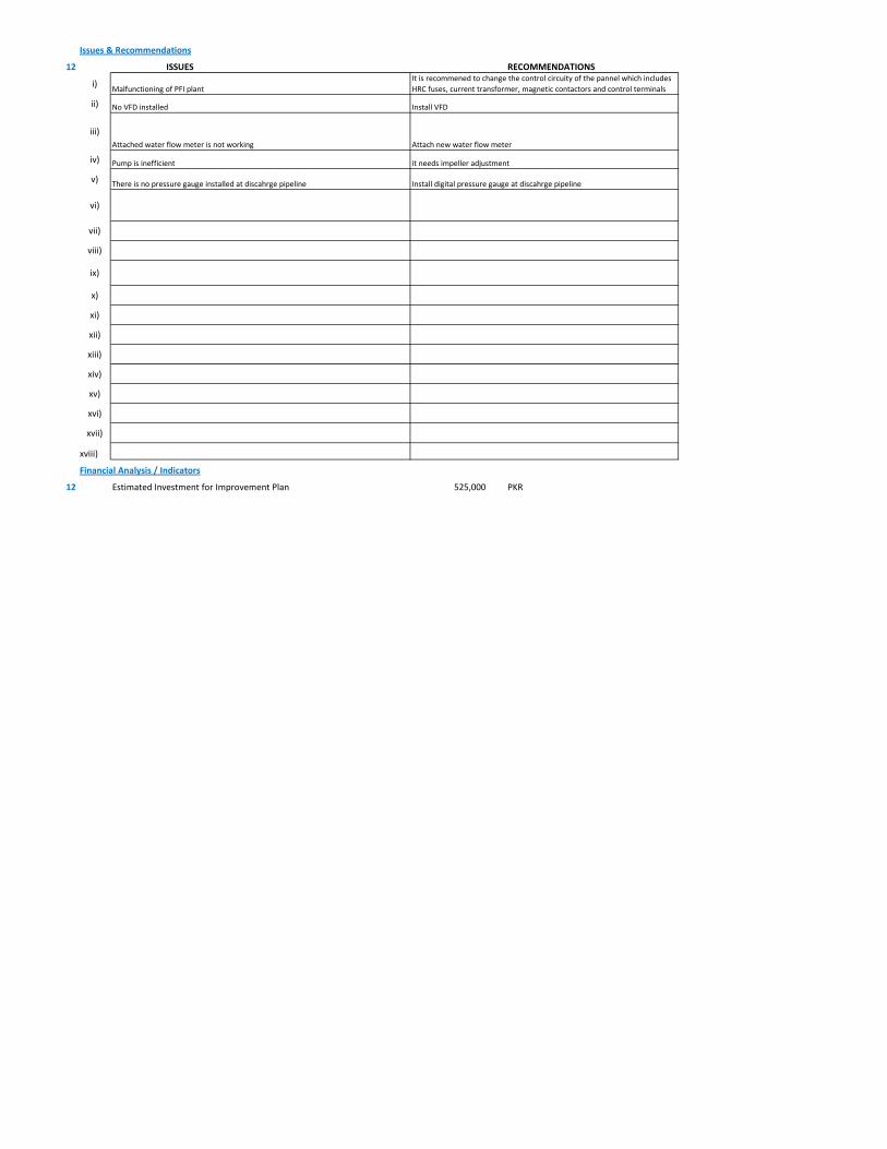
Issues & Recommendations
12 ISSUES RECOMMENDATIONS
i)
ii)
iii)
iv) Pump is inefficient it needs impeller adjustment
v)
vi)
vii)
viii)
ix)
x)
xi)
xii)
xiii)
xiv)
xv)
xvi)
xvii)
xviii)
Financial Analysis / Indicators
12 Estimated Investment for Improvement Plan 525,000 PKR
Install digital pressure gauge at discahrge pipelineThere is no pressure gauge installed at discahrge pipeline
No VFD installed Install VFD
Attached water flow meter is not working Attach new water flow meter
Malfunctioning of PFI plantIt is recommened to change the control circuity of the pannel which includes HRC fuses, current transformer, magnetic contactors and control terminals
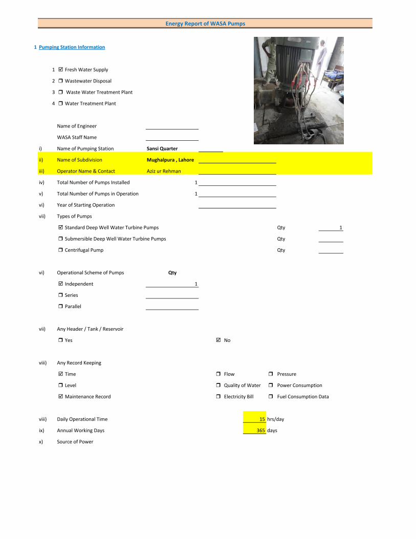
1 Pumping Station Information
1 Fresh Water Supply
2 Wastewater Disposal
3 Waste Water Treatment Plant
4 Water Treatment Plant
Name of Engineer
WASA Staff Name
i) Name of Pumping Station Sansi Quarter
ii) Name of Subdivision Mughalpura , Lahore
iii) Operator Name & Contact Aziz ur Rehman
iv) Total Number of Pumps Installed 1
v) Total Number of Pumps in Operation 1
vi) Year of Starting Operation
vii) Types of Pumps
Standard Deep Well Water Turbine Pumps Qty 1
Submersible Deep Well Water Turbine Pumps Qty
Centrifugal Pump Qty
vi) Operational Scheme of Pumps Qty
Independent 1
Series
Parallel
vii) Any Header / Tank / Reservoir
Yes No
viii) Any Record Keeping
Time Flow Pressure
Level Quality of Water Power Consumption
Maintenance Record Electricity Bill Fuel Consumption Data
viii) Daily Operational Time 15 hrs/day
ix) Annual Working Days 365 days
x) Source of Power
Energy Report of WASA Pumps
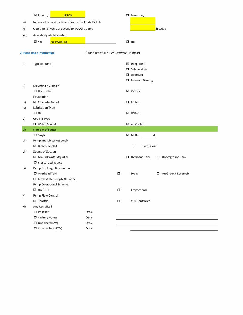
Primary LESCO Secondary
xi) In Case of Secondary Power Source Fuel Data Details
xii) Operational Hours of Secondary Power Source hrs/day
xiii) Availability of Chlorinator
Yes Not Working No
2 Pump Basic Information (Pump Ref # CITY_FWPS/WWDS_Pump #)
i) Type of Pump Deep Well
Submersible
Overhung
Between Bearing
ii) Mounting / Erection
Horizontal Vertical
Foundation
iii) Concrete Bolted Bolted
iv) Lubrication Type
Oil Water
v) Cooling Type
Water Cooled Air Cooled
vi) Number of Stages
Single Multi 4
vii) Pump and Motor Assembly
Direct Coupled Belt / Gear
viii) Source of Suction
Ground Water Aquafier Overhead Tank Underground Tank
Pressurized Source
ix) Pump Discharge Destination
Overhead Tank Drain On Ground Reservoir
Fresh Water Supply Network
Pump Operational Scheme
On / OFF Proportional
x) Pump Flow Control
Throttle VFD Controlled
xi) Any Retrofits ?
Impeller Detail
Casing / Volute Detail
Line Shaft (DW) Detail
Column Sett. (DW) Detail
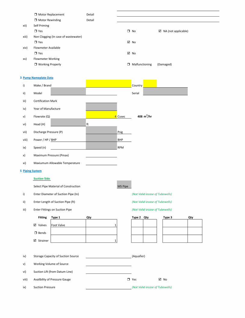
Motor Replacement Detail
Motor Rewinding Detail
xii) Self Priming
Yes No NA (not applicable)
xiii) Non Clogging (In case of wastewater)
Yes No
xiv) Flowmeter Available
Yes No
xv) Flowmeter Working
Working Properly Malfunctioning (Damaged)
3 Pump Nameplate Data
i) Make / Brand Country
ii) Model Serial
iii) Certification Mark
iv) Year of Manufacture
v) Flowrate (Q) 4 Cusec 408 m3/hr
vi) Head (H) ft
vii) Discharge Pressure (P) Psig
viii) Power / HP / BHP BHP
ix) Speed (n) RPM
x) Maximum Pressure (Pmax)
xi) Maxiumum Allowable Temperature
5 Piping System
Suction Side
Select Pipe Material of Construction MS Pipe
i) Enter Diameter of Suction Pipe (In) (Not Valid incase of Tubewells)
ii) Enter Length of Suction Pipe (ft) (Not Valid incase of Tubewells)
iii) Enter Fittings on Suction Pipe (Not Valid incase of Tubewells)
Fitting Type 1 Qty Type 2 Qty Type 3 Qty
Valves Foot Valve 1
Bends
Strainer 1
iv) Storage Capacity of Suction Source (Aquafier)
v) Working Volume of Source
vi) Suction Lift (from Datum Line)
viii) Availbility of Pressure Gauge Yes No
ix) Suction Pressure (Not Valid incase of Tubewells)

Discharge Side
Pipe Material of Construction MS Pipe
i) Diameter of Discharge Pipe 10 inch
ii) Length of Discharge Pipe (Not known as directly connected to network underground)
iii) Fittings on Discharge Pipe
Fitting Type 1 Qty Type 2 Qty Type 3 Qty
Valves Control 1 Check 1
Bends Elbow 1
Strainer
iv) Storage Capacity of Discharge Destination (Not known as directly connected to network underground))
v) Working Volume of Discharge Destination (Not known as directly connected to network underground))
vi) Discharge Elevation (from Datum Line) (In case of no gauge)
vii) Availbility of Pressure Gauge Yes No (Installed by Team)
viii) Discharge Pressure 10 psig
6 Motor Nameplate Data
i) Manufacturer Siemens
ii) Rated kW / hp 150 hp 112.5 kW
iii) Voltage Range (Volts) 380 Volts
iv) Current (Ampere) 214
v) Power Factor (Cos ɸ) 0.85
Efficiency Class
IE3 Eff 1
IE2 Eff 2
IE1 Eff 3
Standard Efficiency
vi) Motor Speed 1,488 RPM
vii) Reference Frequency 50 C/S
viii) Insulation Class F
ix) Motor Frame Size 315 S
x)
7 Electrical System Observations
i) Electrical Meter Reference Number
ii) Meter Reading
iii) Meter Time and Date
Correct FALSE

Lag by Lead by
iv) Transformer Rating (kVA) 200 Condition OK
Pump O & M Cost
v) Motor Starting Method
Direct Online Star (Wye) - Delta
Autotransformer Starter Soft Starter
Variable Frequency Drives
v) Electrical Protections Available
Earthing / Grounding Fuses or Miniature Circuit Breaker (MCB)
Earth Leakage Circuit Breaker (ELCB) and Residual Current Circuit Breaker (RCCB)
PFI Plant Not installed
Panel Condition/Issues poor
Gland Leakage significant leakage
Non Return Valve not working
Chlorinator not operational
Flow Meter not available
Pressure Gauge not available
Bore Hole in Front of Panno
Wiring poor
Housekeeping Fair
Motor Terminal open motor connections
Foundation/Civil work ok
Ratchet Plate Faulty
Field Measurements
8 Flow Measurement
i) Flow Measurement Location
Discharge Pipe Suction Pipe
ii) Pipe Material of Construction MS Pipe
iii) Paint on Pipe Yes No
iv) Pipe Diameter 10 inches (on which flowmeter is clamped)
v) Pipe Perimeter 880 mm (on which flowmeter is clamped)
vi) Type of Clamping (V/N/Z) V
viii) Flow Measurement 240 m3/hr (Through Transit Time Ultrasonic Flowmeter)
Velocity in Pipe 1.32 m/sec
Pressure
i) Pressure at Discharge Side of Pump 10 psig
ii) Pressure at Suction Side of Pump (Not Valid incase of Tubewells)

iii) Water Shutoff Head
Levels
i) Static Water Level 38 meter Estimated
ii) Pumping Water Level 43 meter (estimated due to gland leakage and catching of wire by suction)
Electric Measurements
i) Voltage 390.7 386 388
ii) Ampere 128 143 125
iii) Power Factor 0.79
iv) Appearant Power (kVA) 88.7
v) Running Power (kW) 70
vi) Reactive Power (kVAr) 54.4
vi) Motor Working on Loading Basis 63.7 %
Oversize Undersize Properly Sized
Speed
i) Speed of Motor 1,488 RPM
ii) Speed of Pump Impeller RPM
Noise Level
Noise Level (db(A)) Avg. Max: 90
Thermal Imaging
i) Motor Motor Pump Coupling
Pump Volute Casing Pump Bearings
Electric Panels
Calculations
10
i) Drawdown of Pump (Pumping water level - Static Water Level) 16.4 ft
ii) Static Suction Head (Only for WW Pump) ft
iii) Suction Side Frictional Head (Only for WW Pump) ft
iv) Dynamic Suction Head (ii+iii) (Only for WW Pump) ft
v) Discharge Head (Pressure Gauge) 23.1 ft
vi) Discharge Side Frictional Head 4.31 ft
vii) Dynamic Discharge Head (v+vi) 27.41 ft

viii) Total Dynamic Head of Pump (TDH) (vii + Pumping Water Level) 168.45 ft
ix) Specific Capacity of Pump (Water Turbine) gpm/ft of drawdown 64.43
x) Specific Speed of Pump
Ns = RPM x GPM0.5 / H0.75
impeller rpm necessary to produce 1gpm/ft head 0
500-10,000, standard, 2,000-3,000 high efficiency
xi) Difference of Pump Curve flow and Measured Flow at the TDH m3/hr
xii) Deviation of actual flow from the pump curve flow %
xiii) Water Horsepower (whp) (TDH x Actual Measured Flow) 44.95 hp
xiv) Brake Horsepower (bhp) (OEM Data) 0 hp
xv) Electrical Horsepower(ehp) (Electrical Measurement at Motor input) 93.83 hp
xvi) Efficiency of Individual Pump (ηpump) (whp/bhp) x 100 #DIV/0! %
xvii) Efficiency of Pumping System (ηsystem)Existing (whp/ehp) x 100 47.90 %
xviii) Existing Specific Pumping Energy (En(pumping01)) 0.29 kWh/m3
xix) Avg. Cost of Energy (Based on Grid and Backup) 13 PKR/kWh
xx) Daily Operational Time of Pump 15 hrs
xxi) Daily Pump flow 3,600 m3/day
xxii) Annual working days 365 days
xxiii) Annual Pump flow 1,314,000 m3/yr
xxiv) Annual Energy Consumption of Pump (En(pumping01) x Annual Pump Flow) 385,305 kWh/yr
xxv) Annual Energy Expenditure on Pumping 5,008,964 PKR/Yr
xxvi) Pumping System Efficiency after Improvement 65 %
xxvii) Water Flow after Efficiency Improvement 326 m3/hr
xxviii) Specific Energy Consumption at New Efficiency 0.22 kWh/m3
xxix) Potential of Energy Reduction 26.30 %
xxx) Reduced Annual Energy Consumption at Improved Efficiency 101,341 kWh/yr
xxxi) Annual Financial Saving on Pumping 1,317,436 PKR/Yr
11 Summary of Findings
Pumping system efficiency is 47.90%. For pump attached with 150 HP motor, efficiency below 58% is considered LOW. This pumping system requires impellers adjustment and repair and maintenance. The efficiency will be improved from 47.90% to 65% with annual saving of Rs. 1,317,436.
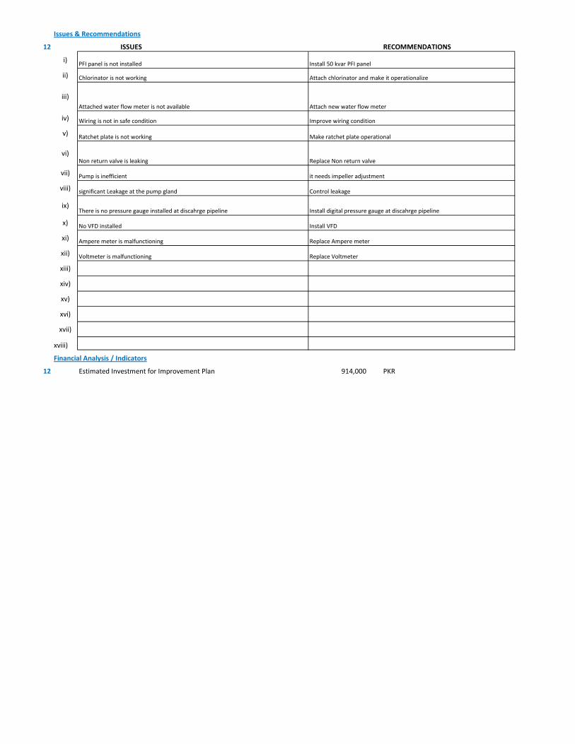
Issues & Recommendations
12 ISSUES RECOMMENDATIONS
i)
ii)
iii)
iv)
v)
vi)
vii)
viii)
ix)
x)
xi)
xii)
xiii)
xiv)
xv)
xvi)
xvii)
xviii)
Financial Analysis / Indicators
12 Estimated Investment for Improvement Plan 914,000 PKR
Voltmeter is malfunctioning Replace Voltmeter
Control leakagesignificant Leakage at the pump gland
Replace Non return valveNon return valve is leaking
No VFD installed Install VFD
Pump is inefficient it needs impeller adjustment
Ampere meter is malfunctioning Replace Ampere meter
There is no pressure gauge installed at discahrge pipeline Install digital pressure gauge at discahrge pipeline
PFI panel is not installed Install 50 kvar PFI panel
Make ratchet plate operationalRatchet plate is not working
Improve wiring conditionWiring is not in safe condition
Chlorinator is not working Attach chlorinator and make it operationalize
Attached water flow meter is not available Attach new water flow meter

1 Pumping Station Information
1 Fresh Water Supply
2 Wastewater Disposal
3 Waste Water Treatment Plant
4 Water Treatment Plant
Name of Engineer
WASA Staff Name
i) Name of Pumping Station Angoori Bagh Scheme No.2
ii) Name of Subdivision Mughalpura , Lahore
iii) Operator Name & Contact Naveed
iv) Total Number of Pumps Installed 1
v) Total Number of Pumps in Operation 1
vi) Year of Starting Operation
vii) Types of Pumps
Standard Deep Well Water Turbine Pumps Qty 1
Submersible Deep Well Water Turbine Pumps Qty
Centrifugal Pump Qty
vi) Operational Scheme of Pumps Qty
Independent 1
Series
Parallel
vii) Any Header / Tank / Reservoir
Yes No
viii) Any Record Keeping
Time Flow Pressure
Level Quality of Water Power Consumption
Maintenance Record Electricity Bill Fuel Consumption Data
viii) Daily Operational Time 15 hrs/day
ix) Annual Working Days 365 days
x) Source of Power
Energy Report of WASA Pumps

Primary LESCO Secondary
xi) In Case of Secondary Power Source Fuel Data Details
xii) Operational Hours of Secondary Power Source hrs/day
xiii) Availability of Chlorinator
Yes No
2 Pump Basic Information (Pump Ref # CITY_FWPS/WWDS_Pump #)
i) Type of Pump Deep Well
Submersible
Overhung
Between Bearing
ii) Mounting / Erection
Horizontal Vertical
Foundation
iii) Concrete Bolted Bolted
iv) Lubrication Type
Oil Water
v) Cooling Type
Water Cooled Air Cooled
vi) Number of Stages
Single Multi 5
vii) Pump and Motor Assembly
Direct Coupled Belt / Gear
viii) Source of Suction
Ground Water Aquafier Overhead Tank Underground Tank
Pressurized Source
ix) Pump Discharge Destination
Overhead Tank Drain On Ground Reservoir
Fresh Water Supply Network
Pump Operational Scheme
On / OFF Proportional
x) Pump Flow Control
Throttle VFD Controlled
xi) Any Retrofits ?
Impeller Detail
Casing / Volute Detail
Line Shaft (DW) Detail
Column Sett. (DW) Detail

Motor Replacement Detail
Motor Rewinding Detail
xii) Self Priming
Yes No NA (not applicable)
xiii) Non Clogging (In case of wastewater)
Yes No
xiv) Flowmeter Available
Yes No
xv) Flowmeter Working
Working Properly Malfunctioning (Damaged)
3 Pump Nameplate Data
i) Make / Brand Country
ii) Model Serial
iii) Certification Mark
iv) Year of Manufacture
v) Flowrate (Q) 2 Cusec 204 m3/hr
vi) Head (H) ft
vii) Discharge Pressure (P) Psig
viii) Power / HP / BHP BHP
ix) Speed (n) RPM
x) Maximum Pressure (Pmax)
xi) Maxiumum Allowable Temperature
5 Piping System
Suction Side
Select Pipe Material of Construction MS Pipe
i) Enter Diameter of Suction Pipe (In) (Not Valid incase of Tubewells)
ii) Enter Length of Suction Pipe (ft) (Not Valid incase of Tubewells)
iii) Enter Fittings on Suction Pipe (Not Valid incase of Tubewells)
Fitting Type 1 Qty Type 2 Qty Type 3 Qty
Valves Foot Valve 1
Bends
Strainer 1
iv) Storage Capacity of Suction Source (Aquafier)
v) Working Volume of Source
vi) Suction Lift (from Datum Line)
viii) Availbility of Pressure Gauge Yes No
ix) Suction Pressure (Not Valid incase of Tubewells)

Discharge Side
Pipe Material of Construction MS Pipe
i) Diameter of Discharge Pipe 8 inch
ii) Length of Discharge Pipe (Not known as directly connected to network underground)
iii) Fittings on Discharge Pipe
Fitting Type 1 Qty Type 2 Qty Type 3 Qty
Valves Control 1 Check 1
Bends Elbow 1
Strainer
iv) Storage Capacity of Discharge Destination (Not known as directly connected to network underground))
v) Working Volume of Discharge Destination (Not known as directly connected to network underground))
vi) Discharge Elevation (from Datum Line) (In case of no gauge)
vii) Availbility of Pressure Gauge Yes No (Installed by Team)
viii) Discharge Pressure 6 psig
6 Motor Nameplate Data
i) Manufacturer Siemens
ii) Rated kW / hp 80 hp 60 kW
iii) Voltage Range (Volts) 380 Volts
iv) Current (Ampere) 115
v) Power Factor (Cos ɸ) 0.85
Efficiency Class
IE3 Eff 1
IE2 Eff 2
IE1 Eff 3
Standard Efficiency
vi) Motor Speed 1,488 RPM
vii) Reference Frequency 50 C/S
viii) Insulation Class F
ix) Motor Frame Size 250 M
x)
7 Electrical System Observations
i) Electrical Meter Reference Number
ii) Meter Reading
iii) Meter Time and Date
Correct FALSE

Lag by Lead by
iv) Transformer Rating (kVA) 100 Condition OK
Pump O & M Cost
v) Motor Starting Method
Direct Online Star (Wye) - Delta
Autotransformer Starter Soft Starter
Variable Frequency Drives
v) Electrical Protections Available
Earthing / Grounding Fuses or Miniature Circuit Breaker (MCB)
Earth Leakage Circuit Breaker (ELCB) and Residual Current Circuit Breaker (RCCB)
PFI Plant 15kvar(Non-operational)
Panel Condition/Issues Good
Gland Leakage Minor leakage
Non Return Valve ok
Chlorinator Not Available
Flow Meter Available(Not working)
Pressure Gauge Not Available
Bore Hole in Front of Panno
Wiring Good
Housekeeping Fair
Motor Terminal
Foundation/Civil work ok
Ratchet Plate ok
Field Measurements
8 Flow Measurement
i) Flow Measurement Location
Discharge Pipe Suction Pipe
ii) Pipe Material of Construction MS Pipe
iii) Paint on Pipe Yes No
iv) Pipe Diameter 8 inches (on which flowmeter is clamped)
v) Pipe Perimeter 720 mm (on which flowmeter is clamped)
vi) Type of Clamping (V/N/Z) V
viii) Flow Measurement 120 m3/hr (Through Transit Time Ultrasonic Flowmeter)
Velocity in Pipe 1.03 m/sec
Pressure
i) Pressure at Discharge Side of Pump 6 psig
ii) Pressure at Suction Side of Pump (Not Valid incase of Tubewells)

iii) Water Shutoff Head
Levels
i) Static Water Level 38 meter Estimated
ii) Pumping Water Level 43 meter (estimated due to gland leakage and catching of wire by suction)
Electric Measurements
i) Voltage 432 430 431.2
ii) Ampere 66.9 69.2 67.7
iii) Power Factor 0.79
iv) Appearant Power (kVA) 50.7
v) Running Power (kW) 40
vi) Reactive Power (kVAr) 31.1
vi) Motor Working on Loading Basis 66.7 %
Oversize Undersize Properly Sized
Speed
i) Speed of Motor 1,488 RPM
ii) Speed of Pump Impeller RPM
Noise Level
Noise Level (db(A)) Avg. Max:
Thermal Imaging
i) Motor Motor Pump Coupling
Pump Volute Casing Pump Bearings
Electric Panels
Calculations
10
i) Drawdown of Pump (Pumping water level - Static Water Level) 16.4 ft
ii) Static Suction Head (Only for WW Pump) ft
iii) Suction Side Frictional Head (Only for WW Pump) ft
iv) Dynamic Suction Head (ii+iii) (Only for WW Pump) ft
v) Discharge Head (Pressure Gauge) 13.86 ft
vi) Discharge Side Frictional Head 2.79 ft
vii) Dynamic Discharge Head (v+vi) 16.65 ft

viii) Total Dynamic Head of Pump (TDH) (vii + Pumping Water Level) 157.69 ft
ix) Specific Capacity of Pump (Water Turbine) gpm/ft of drawdown 32.22
x) Specific Speed of Pump
Ns = RPM x GPM0.5 / H0.75
impeller rpm necessary to produce 1gpm/ft head 0
500-10,000, standard, 2,000-3,000 high efficiency
xi) Difference of Pump Curve flow and Measured Flow at the TDH m3/hr
xii) Deviation of actual flow from the pump curve flow %
xiii) Water Horsepower (whp) (TDH x Actual Measured Flow) 21.04 hp
xiv) Brake Horsepower (bhp) (OEM Data) 0 hp
xv) Electrical Horsepower(ehp) (Electrical Measurement at Motor input) 53.62 hp
xvi) Efficiency of Individual Pump (ηpump) (whp/bhp) x 100 #DIV/0! %
xvii) Efficiency of Pumping System (ηsystem)Existing (whp/ehp) x 100 39.24 %
xviii) Existing Specific Pumping Energy (En(pumping01)) 0.34 kWh/m3
xix) Avg. Cost of Energy (Based on Grid and Backup) 13 PKR/kWh
xx) Daily Operational Time of Pump 15 hrs
xxi) Daily Pump flow 1,800 m3/day
xxii) Annual working days 365 days
xxiii) Annual Pump flow 657,000 m3/yr
xxiv) Annual Energy Consumption of Pump (En(pumping01) x Annual Pump Flow) 220,174 kWh/yr
xxv) Annual Energy Expenditure on Pumping 2,862,265 PKR/Yr
xxvi) Pumping System Efficiency after Improvement 62 %
xxvii) Water Flow after Efficiency Improvement 190 m3/hr
xxviii) Specific Energy Consumption at New Efficiency 0.21 kWh/m3
xxix) Potential of Energy Reduction 36.71 %
xxx) Reduced Annual Energy Consumption at Improved Efficiency 80,831 kWh/yr
xxxi) Annual Financial Saving on Pumping 1,050,797 PKR/Yr
11 Summary of Findings
Pumping system efficiency is 39.24% For pump attached with 80 HP motor, efficiency below 56% is considered to be LOW (> 65.9 is
excellent). This pumping system requires impeller adjustment,repair and maintenance. It is estimated that this impeller adjustment,repair and maintenance would increase pumping efficiency from 39.24% to 62% which is in the range of GOOD efficiency. This efficiency improvement will save about Rs. 1,050,797 per year.
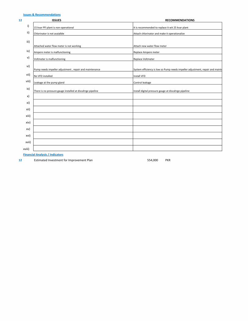
Issues & Recommendations
12 ISSUES RECOMMENDATIONS
i)
ii)
iii)
iv)
v)
vi)
vii)
viii)
ix)
x)
xi)
xii)
xiii)
xiv)
xv)
xvi)
xvii)
xviii)
Financial Analysis / Indicators
12 Estimated Investment for Improvement Plan 554,000 PKR
Replace Voltmeter Voltmeter is malfunctioning
Replace Ampere meterAmpere meter is malfunctioning
Chlorinator is not avaialble Attach chlorinator and make it operationalize
Attached water flow meter is not working Attach new water flow meter
15 kvar PFI plant is non-operational It is recommended to replace it wit 25 kvar plant
Control leakageLeakage at the pump gland
System efficiency is low so Pump needs impeller adjustment, repair and mainte Pump needs impeller adjustment , repair and maintenance
No VFD installed Install VFD
There is no pressure gauge installed at discahrge pipeline Install digital pressure gauge at discahrge pipeline
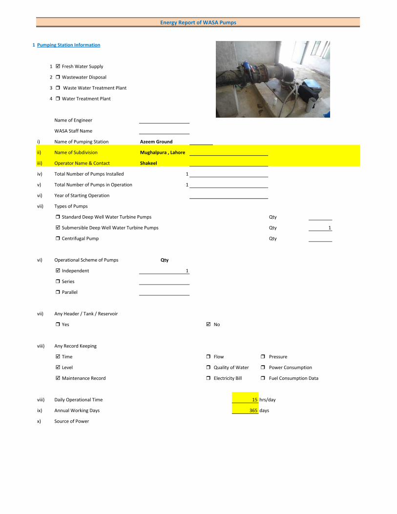
1 Pumping Station Information
1 Fresh Water Supply
2 Wastewater Disposal
3 Waste Water Treatment Plant
4 Water Treatment Plant
Name of Engineer
WASA Staff Name
i) Name of Pumping Station Azeem Ground
ii) Name of Subdivision Mughalpura , Lahore
iii) Operator Name & Contact Shakeel
iv) Total Number of Pumps Installed 1
v) Total Number of Pumps in Operation 1
vi) Year of Starting Operation
vii) Types of Pumps
Standard Deep Well Water Turbine Pumps Qty
Submersible Deep Well Water Turbine Pumps Qty 1
Centrifugal Pump Qty
vi) Operational Scheme of Pumps Qty
Independent 1
Series
Parallel
vii) Any Header / Tank / Reservoir
Yes No
viii) Any Record Keeping
Time Flow Pressure
Level Quality of Water Power Consumption
Maintenance Record Electricity Bill Fuel Consumption Data
viii) Daily Operational Time 15 hrs/day
ix) Annual Working Days 365 days
x) Source of Power
Energy Report of WASA Pumps

Primary LESCO Secondary
xi) In Case of Secondary Power Source Fuel Data Details
xii) Operational Hours of Secondary Power Source hrs/day
xiii) Availability of Chlorinator
Yes No
2 Pump Basic Information (Pump Ref # CITY_FWPS/WWDS_Pump #)
i) Type of Pump Deep Well
Submersible
Overhung
Between Bearing
ii) Mounting / Erection
Horizontal Vertical
Foundation
iii) Concrete Bolted Bolted
iv) Lubrication Type
Oil Water
v) Cooling Type
Water Cooled Air Cooled
vi) Number of Stages
Single Multi 5
vii) Pump and Motor Assembly
Direct Coupled Belt / Gear
viii) Source of Suction
Ground Water Aquafier Overhead Tank Underground Tank
Pressurized Source
ix) Pump Discharge Destination
Overhead Tank Drain On Ground Reservoir
Fresh Water Supply Network
Pump Operational Scheme
On / OFF Proportional
x) Pump Flow Control
Throttle VFD Controlled
xi) Any Retrofits ?
Impeller Detail
Casing / Volute Detail
Line Shaft (DW) Detail
Column Sett. (DW) Detail

Motor Replacement Detail
Motor Rewinding Detail
xii) Self Priming
Yes No NA (not applicable)
xiii) Non Clogging (In case of wastewater)
Yes No
xiv) Flowmeter Available
Yes No
xv) Flowmeter Working
Working Properly Malfunctioning (Damaged)
3 Pump Nameplate Data
i) Make / Brand KSB Pumps Country Pakistan
ii) Model BPN 400/03 Serial 9972397651/100
iii) Certification Mark
iv) Year of Manufacture
v) Flowrate (Q) 2 Cusec 204 m3/hr
vi) Head (H) 250 ft
vii) Discharge Pressure (P) Psig
viii) Power / HP / BHP 71.9 BHP
ix) Speed (n) 2,900 RPM
x) Maximum Pressure (Pmax)
xi) Maxiumum Allowable Temperature
5 Piping System
Suction Side
Select Pipe Material of Construction MS Pipe
i) Enter Diameter of Suction Pipe (In) (Not Valid incase of Tubewells)
ii) Enter Length of Suction Pipe (ft) (Not Valid incase of Tubewells)
iii) Enter Fittings on Suction Pipe (Not Valid incase of Tubewells)
Fitting Type 1 Qty Type 2 Qty Type 3 Qty
Valves Foot Valve 1
Bends
Strainer 1
iv) Storage Capacity of Suction Source (Aquafier)
v) Working Volume of Source
vi) Suction Lift (from Datum Line)
viii) Availbility of Pressure Gauge Yes No
ix) Suction Pressure (Not Valid incase of Tubewells)
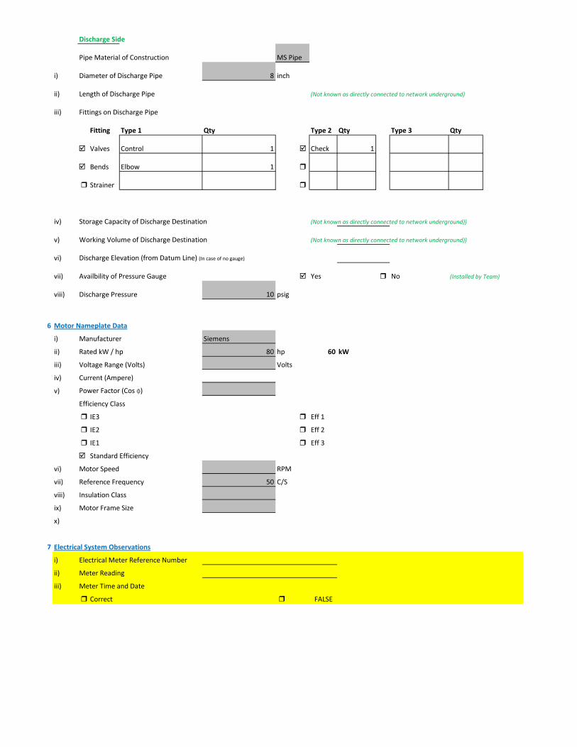
Discharge Side
Pipe Material of Construction MS Pipe
i) Diameter of Discharge Pipe 8 inch
ii) Length of Discharge Pipe (Not known as directly connected to network underground)
iii) Fittings on Discharge Pipe
Fitting Type 1 Qty Type 2 Qty Type 3 Qty
Valves Control 1 Check 1
Bends Elbow 1
Strainer
iv) Storage Capacity of Discharge Destination (Not known as directly connected to network underground))
v) Working Volume of Discharge Destination (Not known as directly connected to network underground))
vi) Discharge Elevation (from Datum Line) (In case of no gauge)
vii) Availbility of Pressure Gauge Yes No (Installed by Team)
viii) Discharge Pressure 10 psig
6 Motor Nameplate Data
i) Manufacturer Siemens
ii) Rated kW / hp 80 hp 60 kW
iii) Voltage Range (Volts) Volts
iv) Current (Ampere)
v) Power Factor (Cos ɸ)
Efficiency Class
IE3 Eff 1
IE2 Eff 2
IE1 Eff 3
Standard Efficiency
vi) Motor Speed RPM
vii) Reference Frequency 50 C/S
viii) Insulation Class
ix) Motor Frame Size
x)
7 Electrical System Observations
i) Electrical Meter Reference Number
ii) Meter Reading
iii) Meter Time and Date
Correct FALSE

Lag by Lead by
iv) Transformer Rating (kVA) 100 Condition OK
Pump O & M Cost
v) Motor Starting Method
Direct Online Star (Wye) - Delta
Autotransformer Starter Soft Starter
Variable Frequency Drives
v) Electrical Protections Available
Earthing / Grounding Fuses or Miniature Circuit Breaker (MCB)
Earth Leakage Circuit Breaker (ELCB) and Residual Current Circuit Breaker (RCCB)
PFI Plant 50kvar(Non-operational)
Panel Condition/Issues Excellent
Gland Leakage No leakage
Non Return Valve Not working(leak)
Chlorinator Not Available
Flow Meter Not Available
Pressure Gauge Yes
Bore Hole in Front of Panno
Wiring good
Housekeeping Fair
Motor Terminal ok
Foundation/Civil work ok
Ratchet Plate
Field Measurements
8 Flow Measurement
i) Flow Measurement Location
Discharge Pipe Suction Pipe
ii) Pipe Material of Construction MS Pipe
iii) Paint on Pipe Yes No
iv) Pipe Diameter 8 inches (on which flowmeter is clamped)
v) Pipe Perimeter 720 mm (on which flowmeter is clamped)
vi) Type of Clamping (V/N/Z) V
viii) Flow Measurement 258 m3/hr (Through Transit Time Ultrasonic Flowmeter)
Velocity in Pipe 2.21 m/sec
Pressure
i) Pressure at Discharge Side of Pump 10 psig
ii) Pressure at Suction Side of Pump (Not Valid incase of Tubewells)

iii) Water Shutoff Head
Levels
i) Static Water Level 38 meter Estimated
ii) Pumping Water Level 43 meter (estimated due to gland leakage and catching of wire by suction)
Electric Measurements
i) Voltage 388.4 386 386
ii) Ampere 107.5 104 116
iii) Power Factor 0.86
iv) Appearant Power (kVA) 73.1
v) Running Power (kW) 62.8
vi) Reactive Power (kVAr) 37.3
vi) Motor Working on Loading Basis 104.7 %
Oversize Undersize Properly Sized
Speed
i) Speed of Motor RPM
ii) Speed of Pump Impeller 2,900 RPM
Noise Level
Noise Level (db(A)) Avg. Max: 71
Thermal Imaging
i) Motor Motor Pump Coupling
Pump Volute Casing Pump Bearings
Electric Panels
Calculations
10
i) Drawdown of Pump (Pumping water level - Static Water Level) 16.4 ft
ii) Static Suction Head (Only for WW Pump) ft
iii) Suction Side Frictional Head (Only for WW Pump) ft
iv) Dynamic Suction Head (ii+iii) (Only for WW Pump) ft
v) Discharge Head (Pressure Gauge) 23.1 ft
vi) Discharge Side Frictional Head 12.58 ft
vii) Dynamic Discharge Head (v+vi) 35.68 ft

viii) Total Dynamic Head of Pump (TDH) (vii + Pumping Water Level) 176.72 ft
ix) Specific Capacity of Pump (Water Turbine) gpm/ft of drawdown 69.27
x) Specific Speed of Pump
Ns = RPM x GPM0.5 / H0.75
impeller rpm necessary to produce 1gpm/ft head 2,017
500-10,000, standard, 2,000-3,000 high efficiency
xi) Difference of Pump Curve flow and Measured Flow at the TDH m3/hr
xii) Deviation of actual flow from the pump curve flow %
xiii) Water Horsepower (whp) (TDH x Actual Measured Flow) 50.69 hp
xiv) Brake Horsepower (bhp) (OEM Data) 71.9 hp
xv) Electrical Horsepower(ehp) (Electrical Measurement at Motor input) 84.18 hp
xvi) Efficiency of Individual Pump (ηpump) (whp/bhp) x 100 70.51 %
xvii) Efficiency of Pumping System (ηsystem)Existing (whp/ehp) x 100 60.22 %
xviii) Existing Specific Pumping Energy (En(pumping01)) 0.24 kWh/m3
xix) Avg. Cost of Energy (Based on Grid and Backup) 13 PKR/kWh
xx) Daily Operational Time of Pump 15 hrs
xxi) Daily Pump flow 3,870 m3/day
xxii) Annual working days 365 days
xxiii) Annual Pump flow 1,412,550 m3/yr
xxiv) Annual Energy Consumption of Pump (En(pumping01) x Annual Pump Flow) 345,674 kWh/yr
xxv) Annual Energy Expenditure on Pumping 4,493,757 PKR/Yr
xxvi) Pumping System Efficiency after Improvement 62 %
xxvii) Water Flow after Efficiency Improvement 266 m3/hr
xxviii) Specific Energy Consumption at New Efficiency 0.24 kWh/m3
xxix) Potential of Energy Reduction 2.87 %
xxx) Reduced Annual Energy Consumption at Improved Efficiency 9,927 kWh/yr
xxxi) Annual Financial Saving on Pumping 129,053 PKR/Yr
11 Summary of Findings
Pumping system efficiency is 60.22%. For pump attached with 80 HP motor, efficiency between 56 - 61 is considered to be FAIR (> 65.9 is
excellent). This pumping system requires impeller adjustment. It is estimated that this impeller adjustment would increase pumping efficiency from 60.22% to 62% which is in the range of GOOD efficiency. This efficiency improvement will save about Rs. 129,053 per year. Motor is overloaded so install new motor.
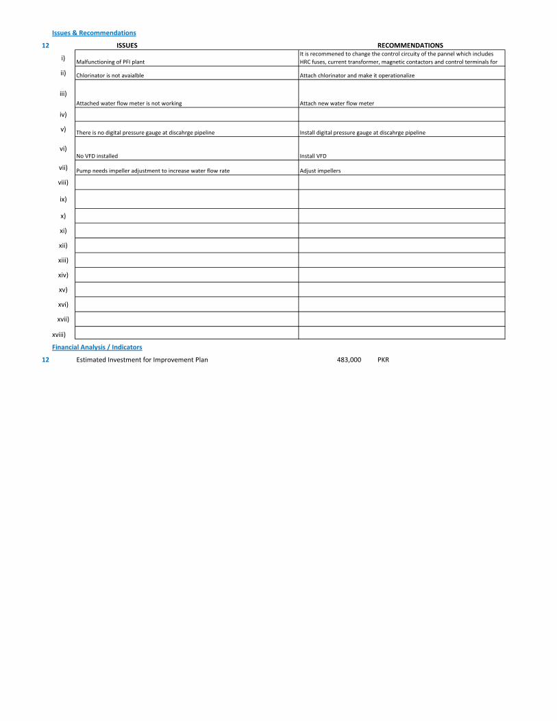
Issues & Recommendations
12 ISSUES RECOMMENDATIONS
i)
ii)
iii)
iv)
v)
vi)
vii)
viii)
ix)
x)
xi)
xii)
xiii)
xiv)
xv)
xvi)
xvii)
xviii)
Financial Analysis / Indicators
12 Estimated Investment for Improvement Plan 483,000 PKR
Install VFDNo VFD installed
Pump needs impeller adjustment to increase water flow rate Adjust impellers
Malfunctioning of PFI plantIt is recommened to change the control circuity of the pannel which includes HRC fuses, current transformer, magnetic contactors and control terminals for
Install digital pressure gauge at discahrge pipelineThere is no digital pressure gauge at discahrge pipeline
Chlorinator is not avaialble Attach chlorinator and make it operationalize
Attached water flow meter is not working Attach new water flow meter
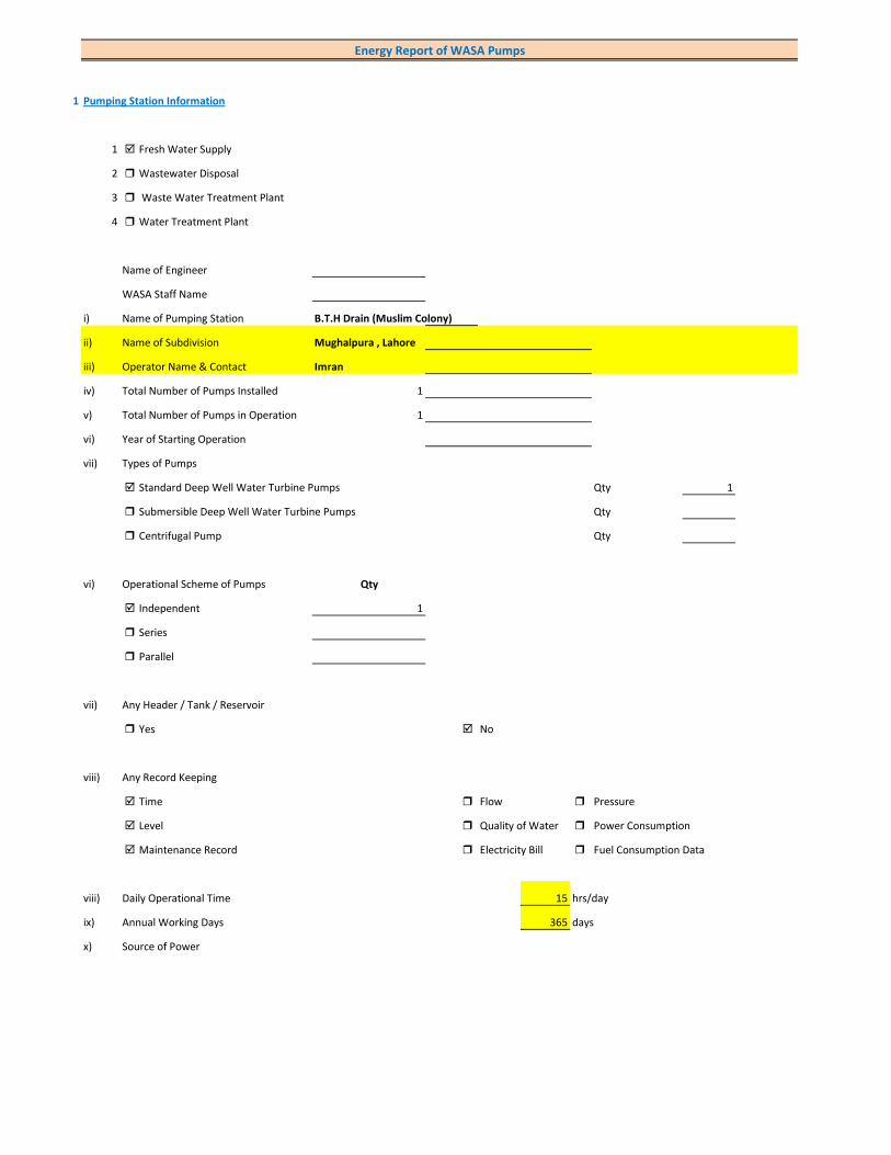
1 Pumping Station Information
1 Fresh Water Supply
2 Wastewater Disposal
3 Waste Water Treatment Plant
4 Water Treatment Plant
Name of Engineer
WASA Staff Name
i) Name of Pumping Station B.T.H Drain (Muslim Colony)
ii) Name of Subdivision Mughalpura , Lahore
iii) Operator Name & Contact Imran
iv) Total Number of Pumps Installed 1
v) Total Number of Pumps in Operation 1
vi) Year of Starting Operation
vii) Types of Pumps
Standard Deep Well Water Turbine Pumps Qty 1
Submersible Deep Well Water Turbine Pumps Qty
Centrifugal Pump Qty
vi) Operational Scheme of Pumps Qty
Independent 1
Series
Parallel
vii) Any Header / Tank / Reservoir
Yes No
viii) Any Record Keeping
Time Flow Pressure
Level Quality of Water Power Consumption
Maintenance Record Electricity Bill Fuel Consumption Data
viii) Daily Operational Time 15 hrs/day
ix) Annual Working Days 365 days
x) Source of Power
Energy Report of WASA Pumps

Primary LESCO Secondary
xi) In Case of Secondary Power Source Fuel Data Details
xii) Operational Hours of Secondary Power Source hrs/day
xiii) Availability of Chlorinator
Yes No
2 Pump Basic Information (Pump Ref # CITY_FWPS/WWDS_Pump #)
i) Type of Pump Deep Well
Submersible
Overhung
Between Bearing
ii) Mounting / Erection
Horizontal Vertical
Foundation
iii) Concrete Bolted Bolted
iv) Lubrication Type
Oil Water
v) Cooling Type
Water Cooled Air Cooled
vi) Number of Stages
Single Multi 4
vii) Pump and Motor Assembly
Direct Coupled Belt / Gear
viii) Source of Suction
Ground Water Aquafier Overhead Tank Underground Tank
Pressurized Source
ix) Pump Discharge Destination
Overhead Tank Drain On Ground Reservoir
Fresh Water Supply Network
Pump Operational Scheme
On / OFF Proportional
x) Pump Flow Control
Throttle VFD Controlled
xi) Any Retrofits ?
Impeller Detail
Casing / Volute Detail
Line Shaft (DW) Detail
Column Sett. (DW) Detail

Motor Replacement Detail
Motor Rewinding Detail
xii) Self Priming
Yes No NA (not applicable)
xiii) Non Clogging (In case of wastewater)
Yes No
xiv) Flowmeter Available
Yes No
xv) Flowmeter Working
Working Properly Malfunctioning (Damaged)
3 Pump Nameplate Data
i) Make / Brand KSB Pumps Country Pakistan
ii) Model B. 14 B/4 Serial 9972384100/100
iii) Certification Mark
iv) Year of Manufacture 2013
v) Flowrate (Q) 4 Cusec 408 m3/hr
vi) Head (H) 210 ft
vii) Discharge Pressure (P) Psig
viii) Power / HP / BHP 124.6 BHP
ix) Speed (n) 1,450 RPM
x) Maximum Pressure (Pmax)
xi) Maxiumum Allowable Temperature
5 Piping System
Suction Side
Select Pipe Material of Construction MS Pipe
i) Enter Diameter of Suction Pipe (In) (Not Valid incase of Tubewells)
ii) Enter Length of Suction Pipe (ft) (Not Valid incase of Tubewells)
iii) Enter Fittings on Suction Pipe (Not Valid incase of Tubewells)
Fitting Type 1 Qty Type 2 Qty Type 3 Qty
Valves Foot Valve 1
Bends
Strainer 1
iv) Storage Capacity of Suction Source (Aquafier)
v) Working Volume of Source
vi) Suction Lift (from Datum Line)
viii) Availbility of Pressure Gauge Yes No
ix) Suction Pressure (Not Valid incase of Tubewells)

Discharge Side
Pipe Material of Construction MS Pipe
i) Diameter of Discharge Pipe 10 inch
ii) Length of Discharge Pipe (Not known as directly connected to network underground)
iii) Fittings on Discharge Pipe
Fitting Type 1 Qty Type 2 Qty Type 3 Qty
Valves Control 1 Check 1
Bends Elbow 1
Strainer
iv) Storage Capacity of Discharge Destination (Not known as directly connected to network underground))
v) Working Volume of Discharge Destination (Not known as directly connected to network underground))
vi) Discharge Elevation (from Datum Line) (In case of no gauge)
vii) Availbility of Pressure Gauge Yes No (Installed by Team)
viii) Discharge Pressure 10 psig
6 Motor Nameplate Data
i) Manufacturer Siemens
ii) Rated kW / hp 150 hp 112.5 kW
iii) Voltage Range (Volts) 380 Volts
iv) Current (Ampere) 214
v) Power Factor (Cos ɸ) 0.85
Efficiency Class
IE3 Eff 1
IE2 Eff 2
IE1 Eff 3
Standard Efficiency
vi) Motor Speed 1,488 RPM
vii) Reference Frequency 50 C/S
viii) Insulation Class F
ix) Motor Frame Size 315 S
x)
7 Electrical System Observations
i) Electrical Meter Reference Number
ii) Meter Reading
iii) Meter Time and Date
Correct FALSE

Lag by Lead by
iv) Transformer Rating (kVA) 200 Condition OK
Pump O & M Cost
v) Motor Starting Method
Direct Online Star (Wye) - Delta
Autotransformer Starter Soft Starter
Variable Frequency Drives
v) Electrical Protections Available
Earthing / Grounding Fuses or Miniature Circuit Breaker (MCB)
Earth Leakage Circuit Breaker (ELCB) and Residual Current Circuit Breaker (RCCB)
PFI Plant 50kvar(operational)
Panel Condition/Issues Excellent
Gland Leakage moderate leakage
Non Return Valve Not Working
Chlorinator Not Available
Flow Meter Not Available
Pressure Gauge Not Available
Bore Hole in Front of Panno
Wiring Good
Housekeeping Fair
Motor Terminal
Foundation/Civil work ok
Ratchet Plate ok
Field Measurements
8 Flow Measurement
i) Flow Measurement Location
Discharge Pipe Suction Pipe
ii) Pipe Material of Construction MS Pipe
iii) Paint on Pipe Yes No
iv) Pipe Diameter 10 inches (on which flowmeter is clamped)
v) Pipe Perimeter 870 mm (on which flowmeter is clamped)
vi) Type of Clamping (V/N/Z) V
viii) Flow Measurement 410 m3/hr (Through Transit Time Ultrasonic Flowmeter)
Velocity in Pipe 2.25 m/sec
Pressure
i) Pressure at Discharge Side of Pump 10 psig
ii) Pressure at Suction Side of Pump (Not Valid incase of Tubewells)

iii) Water Shutoff Head
Levels
i) Static Water Level 38 meter Estimated
ii) Pumping Water Level 43 meter (estimated due to gland leakage and catching of wire by suction)
Electric Measurements
i) Voltage 398 397.2 395.2
ii) Ampere 176.3 172 170
iii) Power Factor 0.87
iv) Appearant Power (kVA) 118.6
v) Running Power (kW) 103.2
vi) Reactive Power (kVAr) 58.5
vi) Motor Working on Loading Basis 93.8 %
Oversize Undersize Properly Sized
Speed
i) Speed of Motor 1,488 RPM
ii) Speed of Pump Impeller 1,450 RPM
Noise Level
Noise Level (db(A)) Avg. Max: 91.6
Thermal Imaging
i) Motor Motor Pump Coupling
Pump Volute Casing Pump Bearings
Electric Panels
Calculations
10
i) Drawdown of Pump (Pumping water level - Static Water Level) 16.4 ft
ii) Static Suction Head (Only for WW Pump) ft
iii) Suction Side Frictional Head (Only for WW Pump) ft
iv) Dynamic Suction Head (ii+iii) (Only for WW Pump) ft
v) Discharge Head (Pressure Gauge) 23.1 ft
vi) Discharge Side Frictional Head 12.40 ft
vii) Dynamic Discharge Head (v+vi) 35.50 ft

viii) Total Dynamic Head of Pump (TDH) (vii + Pumping Water Level) 176.54 ft
ix) Specific Capacity of Pump (Water Turbine) gpm/ft of drawdown 110.08
x) Specific Speed of Pump
Ns = RPM x GPM0.5 / H0.75
impeller rpm necessary to produce 1gpm/ft head 1,272
500-10,000, standard, 2,000-3,000 high efficiency
xi) Difference of Pump Curve flow and Measured Flow at the TDH m3/hr
xii) Deviation of actual flow from the pump curve flow %
xiii) Water Horsepower (whp) (TDH x Actual Measured Flow) 80.48 hp
xiv) Brake Horsepower (bhp) (OEM Data) 124.6 hp
xv) Electrical Horsepower(ehp) (Electrical Measurement at Motor input) 138.34 hp
xvi) Efficiency of Individual Pump (ηpump) (whp/bhp) x 100 64.59 %
xvii) Efficiency of Pumping System (ηsystem)Existing (whp/ehp) x 100 58.18 %
xviii) Existing Specific Pumping Energy (En(pumping01)) 0.25 kWh/m3
xix) Avg. Cost of Energy (Based on Grid and Backup) 13 PKR/kWh
xx) Daily Operational Time of Pump 15 hrs
xxi) Daily Pump flow 6,150 m3/day
xxii) Annual working days 365 days
xxiii) Annual Pump flow 2,244,750 m3/yr
xxiv) Annual Energy Consumption of Pump (En(pumping01) x Annual Pump Flow) 568,050 kWh/yr
xxv) Annual Energy Expenditure on Pumping 7,384,645 PKR/Yr
xxvi) Pumping System Efficiency after Improvement 65 %
xxvii) Water Flow after Efficiency Improvement 458 m3/hr
xxviii) Specific Energy Consumption at New Efficiency 0.23 kWh/m3
xxix) Potential of Energy Reduction 10.50 %
xxx) Reduced Annual Energy Consumption at Improved Efficiency 59,630 kWh/yr
xxxi) Annual Financial Saving on Pumping 775,185 PKR/Yr
11 Summary of Findings
Pumping system efficiency is 58.18%. For pump attached with 80 HP motor, efficiency between 58.1% - 63.4% is considered to be FAIR (>
68.9 is excellent). This pumping system requires impeller adjustment. It is estimated that this impeller adjustment would increase pumping efficiency from 58.18% to 65% which is in the range of GOOD efficiency. This efficiency improvement will save about Rs. 775,185 per year.
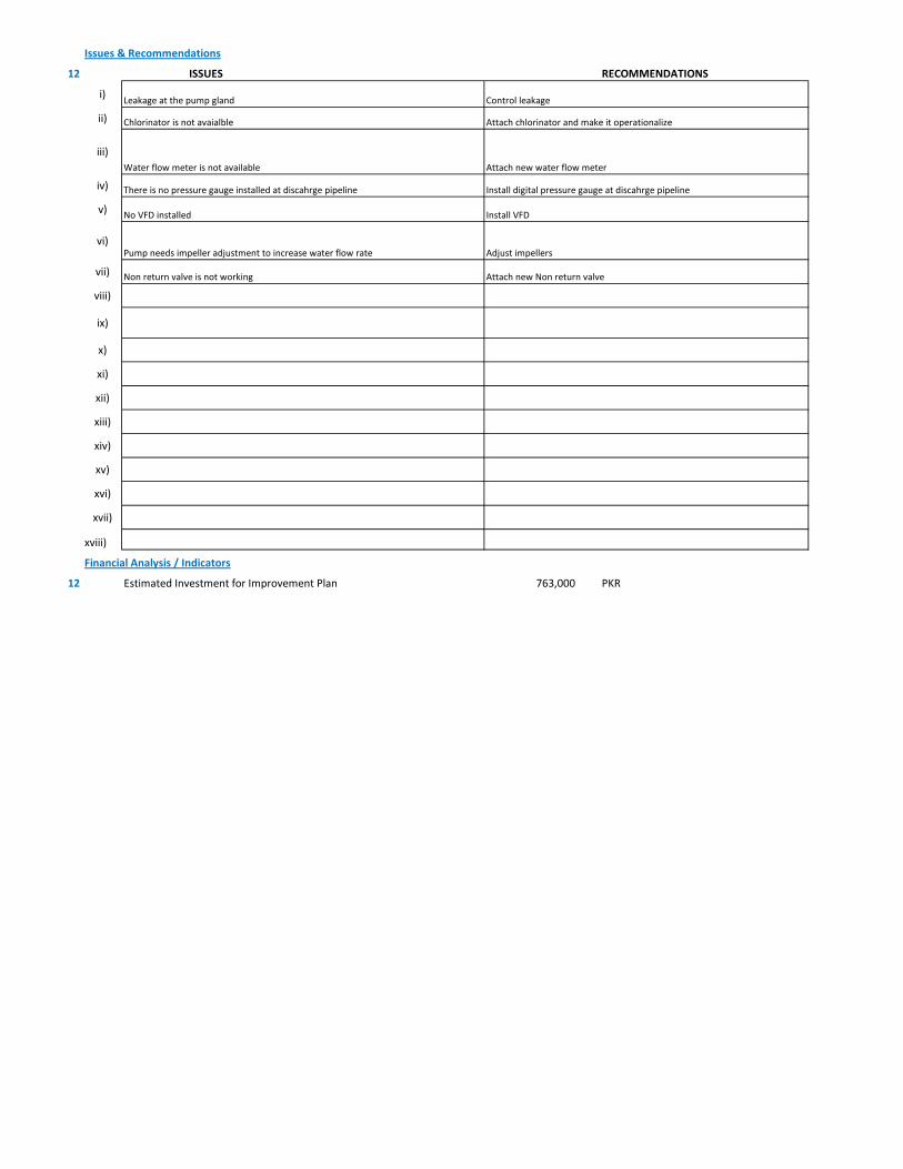
Issues & Recommendations
12 ISSUES RECOMMENDATIONS
i)
ii)
iii)
iv)
v)
vi)
vii)
viii)
ix)
x)
xi)
xii)
xiii)
xiv)
xv)
xvi)
xvii)
xviii)
Financial Analysis / Indicators
12 Estimated Investment for Improvement Plan 763,000 PKR
Install VFDNo VFD installed
Install digital pressure gauge at discahrge pipelineThere is no pressure gauge installed at discahrge pipeline
Chlorinator is not avaialble Attach chlorinator and make it operationalize
Water flow meter is not available Attach new water flow meter
Leakage at the pump gland Control leakage
Adjust impellersPump needs impeller adjustment to increase water flow rate
Non return valve is not working Attach new Non return valve
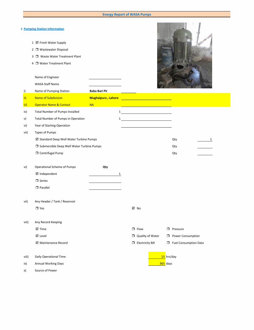
1 Pumping Station Information
1 Fresh Water Supply
2 Wastewater Disposal
3 Waste Water Treatment Plant
4 Water Treatment Plant
Name of Engineer
WASA Staff Name
i) Name of Pumping Station Baba Bari Pir
ii) Name of Subdivision Mughalpura , Lahore
iii) Operator Name & Contact NA
iv) Total Number of Pumps Installed 1
v) Total Number of Pumps in Operation 1
vi) Year of Starting Operation
vii) Types of Pumps
Standard Deep Well Water Turbine Pumps Qty 1
Submersible Deep Well Water Turbine Pumps Qty
Centrifugal Pump Qty
vi) Operational Scheme of Pumps Qty
Independent 1
Series
Parallel
vii) Any Header / Tank / Reservoir
Yes No
viii) Any Record Keeping
Time Flow Pressure
Level Quality of Water Power Consumption
Maintenance Record Electricity Bill Fuel Consumption Data
viii) Daily Operational Time 15 hrs/day
ix) Annual Working Days 365 days
x) Source of Power
Energy Report of WASA Pumps

Primary LESCO Secondary
xi) In Case of Secondary Power Source Fuel Data Details
xii) Operational Hours of Secondary Power Source hrs/day
xiii) Availability of Chlorinator
Yes No
2 Pump Basic Information (Pump Ref # CITY_FWPS/WWDS_Pump #)
i) Type of Pump Deep Well
Submersible
Overhung
Between Bearing
ii) Mounting / Erection
Horizontal Vertical
Foundation
iii) Concrete Bolted Bolted
iv) Lubrication Type
Oil Water
v) Cooling Type
Water Cooled Air Cooled
vi) Number of Stages
Single Multi 5
vii) Pump and Motor Assembly
Direct Coupled Belt / Gear
viii) Source of Suction
Ground Water Aquafier Overhead Tank Underground Tank
Pressurized Source
ix) Pump Discharge Destination
Overhead Tank Drain On Ground Reservoir
Fresh Water Supply Network
Pump Operational Scheme
On / OFF Proportional
x) Pump Flow Control
Throttle VFD Controlled
xi) Any Retrofits ?
Impeller Detail
Casing / Volute Detail
Line Shaft (DW) Detail
Column Sett. (DW) Detail

Motor Replacement Detail
Motor Rewinding Detail
xii) Self Priming
Yes No NA (not applicable)
xiii) Non Clogging (In case of wastewater)
Yes No
xiv) Flowmeter Available
Yes No
xv) Flowmeter Working
Working Properly Malfunctioning (Damaged)
3 Pump Nameplate Data
i) Make / Brand Country
ii) Model Serial
iii) Certification Mark
iv) Year of Manufacture
v) Flowrate (Q) 2 Cusec 204 m3/hr
vi) Head (H) ft
vii) Discharge Pressure (P) Psig
viii) Power / HP / BHP BHP
ix) Speed (n) RPM
x) Maximum Pressure (Pmax)
xi) Maxiumum Allowable Temperature
5 Piping System
Suction Side
Select Pipe Material of Construction MS Pipe
i) Enter Diameter of Suction Pipe (In) (Not Valid incase of Tubewells)
ii) Enter Length of Suction Pipe (ft) (Not Valid incase of Tubewells)
iii) Enter Fittings on Suction Pipe (Not Valid incase of Tubewells)
Fitting Type 1 Qty Type 2 Qty Type 3 Qty
Valves Foot Valve 1
Bends
Strainer 1
iv) Storage Capacity of Suction Source (Aquafier)
v) Working Volume of Source
vi) Suction Lift (from Datum Line)
viii) Availbility of Pressure Gauge Yes No
ix) Suction Pressure (Not Valid incase of Tubewells)

Discharge Side
Pipe Material of Construction MS Pipe
i) Diameter of Discharge Pipe 8 inch
ii) Length of Discharge Pipe (Not known as directly connected to network underground)
iii) Fittings on Discharge Pipe
Fitting Type 1 Qty Type 2 Qty Type 3 Qty
Valves Control 1 Check 1
Bends Elbow 1
Strainer
iv) Storage Capacity of Discharge Destination (Not known as directly connected to network underground))
v) Working Volume of Discharge Destination (Not known as directly connected to network underground))
vi) Discharge Elevation (from Datum Line) (In case of no gauge)
vii) Availbility of Pressure Gauge Yes No (Installed by Team)
viii) Discharge Pressure 6 psig
6 Motor Nameplate Data
i) Manufacturer Siemens
ii) Rated kW / hp 40 hp 30 kW
iii) Voltage Range (Volts) Volts
iv) Current (Ampere)
v) Power Factor (Cos ɸ)
Efficiency Class
IE3 Eff 1
IE2 Eff 2
IE1 Eff 3
Standard Efficiency
vi) Motor Speed RPM
vii) Reference Frequency 50 C/S
viii) Insulation Class
ix) Motor Frame Size
x)
7 Electrical System Observations
i) Electrical Meter Reference Number
ii) Meter Reading
iii) Meter Time and Date
Correct FALSE

Lag by Lead by
iv) Transformer Rating (kVA) 50 Condition OK
Pump O & M Cost
v) Motor Starting Method
Direct Online Star (Wye) - Delta
Autotransformer Starter Soft Starter
Variable Frequency Drives
v) Electrical Protections Available
Earthing / Grounding Fuses or Miniature Circuit Breaker (MCB)
Earth Leakage Circuit Breaker (ELCB) and Residual Current Circuit Breaker (RCCB)
PFI Plant Not installed
Panel Condition/Issues Fair
Gland Leakage Minor leakage
Non Return Valve Not Working
Chlorinator Not Available
Flow Meter Not Available
Pressure Gauge Not Available
Bore Hole in Front of Panno
Wiring Fair
Housekeeping Fair
Motor Terminal open and loose
Foundation/Civil work ok
Ratchet Plate Not Working
Field Measurements
8 Flow Measurement
i) Flow Measurement Location
Discharge Pipe Suction Pipe
ii) Pipe Material of Construction MS Pipe
iii) Paint on Pipe Yes No
iv) Pipe Diameter 8 inches (on which flowmeter is clamped)
v) Pipe Perimeter mm (on which flowmeter is clamped)
vi) Type of Clamping (V/N/Z) V
viii) Flow Measurement 40 m3/hr (Through Transit Time Ultrasonic Flowmeter)
Velocity in Pipe 0.34 m/sec
Pressure
i) Pressure at Discharge Side of Pump 6 psig
ii) Pressure at Suction Side of Pump (Not Valid incase of Tubewells)
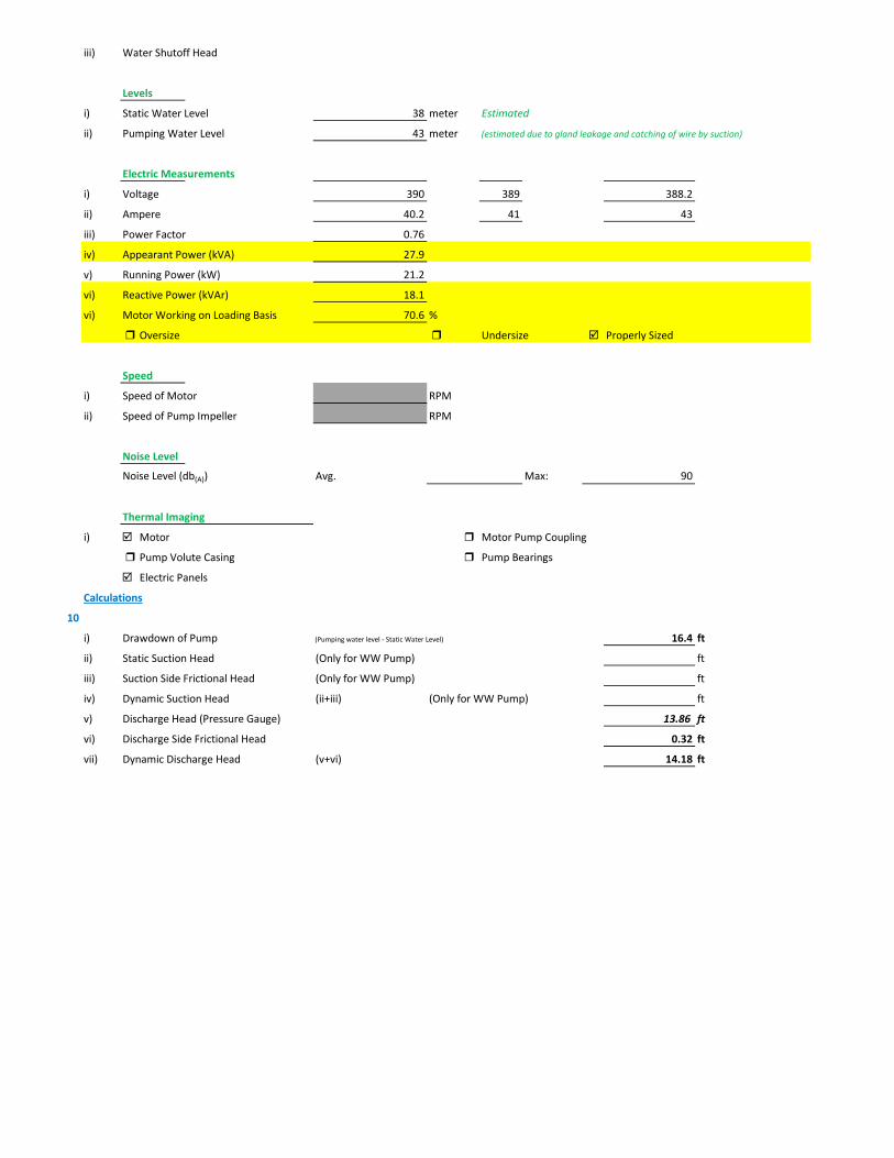
iii) Water Shutoff Head
Levels
i) Static Water Level 38 meter Estimated
ii) Pumping Water Level 43 meter (estimated due to gland leakage and catching of wire by suction)
Electric Measurements
i) Voltage 390 389 388.2
ii) Ampere 40.2 41 43
iii) Power Factor 0.76
iv) Appearant Power (kVA) 27.9
v) Running Power (kW) 21.2
vi) Reactive Power (kVAr) 18.1
vi) Motor Working on Loading Basis 70.6 %
Oversize Undersize Properly Sized
Speed
i) Speed of Motor RPM
ii) Speed of Pump Impeller RPM
Noise Level
Noise Level (db(A)) Avg. Max: 90
Thermal Imaging
i) Motor Motor Pump Coupling
Pump Volute Casing Pump Bearings
Electric Panels
Calculations
10
i) Drawdown of Pump (Pumping water level - Static Water Level) 16.4 ft
ii) Static Suction Head (Only for WW Pump) ft
iii) Suction Side Frictional Head (Only for WW Pump) ft
iv) Dynamic Suction Head (ii+iii) (Only for WW Pump) ft
v) Discharge Head (Pressure Gauge) 13.86 ft
vi) Discharge Side Frictional Head 0.32 ft
vii) Dynamic Discharge Head (v+vi) 14.18 ft

viii) Total Dynamic Head of Pump (TDH) (vii + Pumping Water Level) 155.22 ft
ix) Specific Capacity of Pump (Water Turbine) gpm/ft of drawdown 10.74
x) Specific Speed of Pump
Ns = RPM x GPM0.5 / H0.75
impeller rpm necessary to produce 1gpm/ft head 0
500-10,000, standard, 2,000-3,000 high efficiency
xi) Difference of Pump Curve flow and Measured Flow at the TDH m3/hr
xii) Deviation of actual flow from the pump curve flow %
xiii) Water Horsepower (whp) (TDH x Actual Measured Flow) 6.90 hp
xiv) Brake Horsepower (bhp) (OEM Data) 0 hp
xv) Electrical Horsepower(ehp) (Electrical Measurement at Motor input) 28.42 hp
xvi) Efficiency of Individual Pump (ηpump) (whp/bhp) x 100 #DIV/0! %
xvii) Efficiency of Pumping System (ηsystem)Existing (whp/ehp) x 100 24.29 %
xviii) Existing Specific Pumping Energy (En(pumping01)) 0.53 kWh/m3
xix) Avg. Cost of Energy (Based on Grid and Backup) 13 PKR/kWh
xx) Daily Operational Time of Pump 15 hrs
xxi) Daily Pump flow 600 m3/day
xxii) Annual working days 365 days
xxiii) Annual Pump flow 219,000 m3/yr
xxiv) Annual Energy Consumption of Pump (En(pumping01) x Annual Pump Flow) 116,692 kWh/yr
xxv) Annual Energy Expenditure on Pumping 1,517,001 PKR/Yr
xxvi) Pumping System Efficiency after Improvement 62 %
xxvii) Water Flow after Efficiency Improvement 102 m3/hr
xxviii) Specific Energy Consumption at New Efficiency 0.21 kWh/m3
xxix) Potential of Energy Reduction 60.82 %
xxx) Reduced Annual Energy Consumption at Improved Efficiency 70,971 kWh/yr
xxxi) Annual Financial Saving on Pumping 922,621 PKR/Yr
11 Summary of Findings
Pumping system efficiency is 24.29%. For pump attached with 40 HP motor, efficiency below 52% is considered to be LOW ( > 62% is
excellent). This pumping system requires change(Motor and Pump). It is estimated that this pumping system requires change(Motor and Pump) would increase pumping efficiency from 24.29% to 62% which is in the range of GOOD efficiency. This efficiency improvement will save about Rs. 922,621 per year.
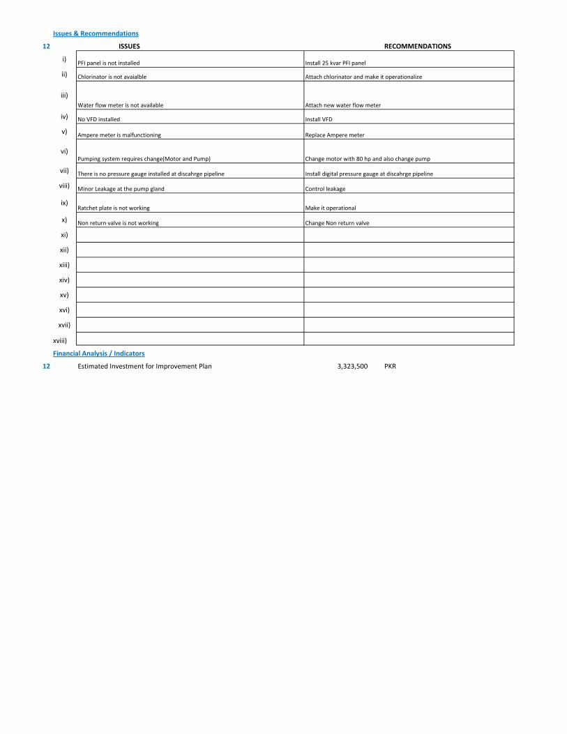
Issues & Recommendations
12 ISSUES RECOMMENDATIONS
i)
ii)
iii)
iv)
v)
vi)
vii)
viii)
ix)
x)
xi)
xii)
xiii)
xiv)
xv)
xvi)
xvii)
xviii)
Financial Analysis / Indicators
12 Estimated Investment for Improvement Plan 3,323,500 PKR
Replace Ampere meterAmpere meter is malfunctioning
Install VFDNo VFD installed
Chlorinator is not avaialble Attach chlorinator and make it operationalize
Water flow meter is not available Attach new water flow meter
PFI panel is not installed Install 25 kvar PFI panel
Control leakageMinor Leakage at the pump gland
Change motor with 80 hp and also change pumpPumping system requires change(Motor and Pump)
Non return valve is not working Change Non return valve
There is no pressure gauge installed at discahrge pipeline Install digital pressure gauge at discahrge pipeline
Ratchet plate is not working Make it operational
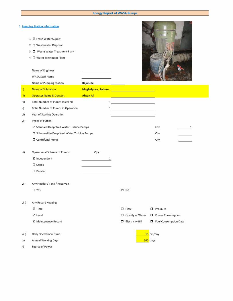
1 Pumping Station Information
1 Fresh Water Supply
2 Wastewater Disposal
3 Waste Water Treatment Plant
4 Water Treatment Plant
Name of Engineer
WASA Staff Name
i) Name of Pumping Station Baja Line
ii) Name of Subdivision Mughalpura , Lahore
iii) Operator Name & Contact Ahsan Ali
iv) Total Number of Pumps Installed 1
v) Total Number of Pumps in Operation 1
vi) Year of Starting Operation
vii) Types of Pumps
Standard Deep Well Water Turbine Pumps Qty 1
Submersible Deep Well Water Turbine Pumps Qty
Centrifugal Pump Qty
vi) Operational Scheme of Pumps Qty
Independent 1
Series
Parallel
vii) Any Header / Tank / Reservoir
Yes No
viii) Any Record Keeping
Time Flow Pressure
Level Quality of Water Power Consumption
Maintenance Record Electricity Bill Fuel Consumption Data
viii) Daily Operational Time 15 hrs/day
ix) Annual Working Days 365 days
x) Source of Power
Energy Report of WASA Pumps

Primary LESCO Secondary
xi) In Case of Secondary Power Source Fuel Data Details
xii) Operational Hours of Secondary Power Source hrs/day
xiii) Availability of Chlorinator
Yes No
2 Pump Basic Information (Pump Ref # CITY_FWPS/WWDS_Pump #)
i) Type of Pump Deep Well
Submersible
Overhung
Between Bearing
ii) Mounting / Erection
Horizontal Vertical
Foundation
iii) Concrete Bolted Bolted
iv) Lubrication Type
Oil Water
v) Cooling Type
Water Cooled Air Cooled
vi) Number of Stages
Single Multi 5
vii) Pump and Motor Assembly
Direct Coupled Belt / Gear
viii) Source of Suction
Ground Water Aquafier Overhead Tank Underground Tank
Pressurized Source
ix) Pump Discharge Destination
Overhead Tank Drain On Ground Reservoir
Fresh Water Supply Network
Pump Operational Scheme
On / OFF Proportional
x) Pump Flow Control
Throttle VFD Controlled
xi) Any Retrofits ?
Impeller Detail
Casing / Volute Detail
Line Shaft (DW) Detail
Column Sett. (DW) Detail

Motor Replacement Detail
Motor Rewinding Detail
xii) Self Priming
Yes No NA (not applicable)
xiii) Non Clogging (In case of wastewater)
Yes No
xiv) Flowmeter Available
Yes No
xv) Flowmeter Working
Working Properly Malfunctioning (Damaged)
3 Pump Nameplate Data
i) Make / Brand KSB Pumps Country Pakistan
ii) Model B. 12 B/5 Serial 21-05-10-4337
iii) Certification Mark
iv) Year of Manufacture 2006
v) Flowrate (Q) 2 Cusec 204 m3/hr
vi) Head (H) 220 ft
vii) Discharge Pressure (P) Psig
viii) Power / HP / BHP 62.74 BHP
ix) Speed (n) 1,475 RPM
x) Maximum Pressure (Pmax)
xi) Maxiumum Allowable Temperature
5 Piping System
Suction Side
Select Pipe Material of Construction MS Pipe
i) Enter Diameter of Suction Pipe (In) (Not Valid incase of Tubewells)
ii) Enter Length of Suction Pipe (ft) (Not Valid incase of Tubewells)
iii) Enter Fittings on Suction Pipe (Not Valid incase of Tubewells)
Fitting Type 1 Qty Type 2 Qty Type 3 Qty
Valves Foot Valve 1
Bends
Strainer 1
iv) Storage Capacity of Suction Source (Aquafier)
v) Working Volume of Source
vi) Suction Lift (from Datum Line)
viii) Availbility of Pressure Gauge Not Working Yes No
ix) Suction Pressure (Not Valid incase of Tubewells)
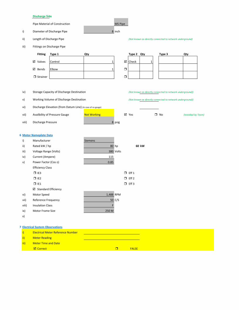
Discharge Side
Pipe Material of Construction MS Pipe
i) Diameter of Discharge Pipe 8 inch
ii) Length of Discharge Pipe (Not known as directly connected to network underground)
iii) Fittings on Discharge Pipe
Fitting Type 1 Qty Type 2 Qty Type 3 Qty
Valves Control 1 Check 1
Bends Elbow 1
Strainer
iv) Storage Capacity of Discharge Destination (Not known as directly connected to network underground))
v) Working Volume of Discharge Destination (Not known as directly connected to network underground))
vi) Discharge Elevation (from Datum Line) (In case of no gauge)
vii) Availbility of Pressure Gauge Not Working Yes No (Installed by Team)
viii) Discharge Pressure 8 psig
6 Motor Nameplate Data
i) Manufacturer Siemens
ii) Rated kW / hp 80 hp 60 kW
iii) Voltage Range (Volts) 380 Volts
iv) Current (Ampere) 115
v) Power Factor (Cos ɸ) 0.85
Efficiency Class
IE3 Eff 1
IE2 Eff 2
IE1 Eff 3
Standard Efficiency
vi) Motor Speed 1,488 RPM
vii) Reference Frequency 50 C/S
viii) Insulation Class F
ix) Motor Frame Size 250 M
x)
7 Electrical System Observations
i) Electrical Meter Reference Number
ii) Meter Reading
iii) Meter Time and Date
Correct FALSE

Lag by Lead by
iv) Transformer Rating (kVA) 100 Condition OK
Pump O & M Cost
v) Motor Starting Method
Direct Online Star (Wye) - Delta
Autotransformer Starter Soft Starter
Variable Frequency Drives
v) Electrical Protections Available
Earthing / Grounding Fuses or Miniature Circuit Breaker (MCB)
Earth Leakage Circuit Breaker (ELCB) and Residual Current Circuit Breaker (RCCB)
PFI Plant 25kvar(Non-operational )
Panel Condition/Issues Very poor
Gland Leakage moderate leakage
Non Return Valve ok
Chlorinator Not Available
Flow Meter Available(Working)
Pressure Gauge Available(Not Working)
Bore Hole in Front of Panyes
Wiring poor
Housekeeping Fair
Motor Terminal no terminal box
Foundation/Civil work ok
Ratchet Plate Not Working
Field Measurements
8 Flow Measurement
i) Flow Measurement Location
Discharge Pipe Suction Pipe
ii) Pipe Material of Construction MS Pipe
iii) Paint on Pipe Yes No
iv) Pipe Diameter 8 inches (on which flowmeter is clamped)
v) Pipe Perimeter mm (on which flowmeter is clamped)
vi) Type of Clamping (V/N/Z) V
viii) Flow Measurement 156 m3/hr (Through Transit Time Ultrasonic Flowmeter)
Velocity in Pipe 1.34 m/sec
Pressure
i) Pressure at Discharge Side of Pump 8 psig
ii) Pressure at Suction Side of Pump (Not Valid incase of Tubewells)

iii) Water Shutoff Head
Levels
i) Static Water Level 38 meter Estimated
ii) Pumping Water Level 43 meter (estimated due to gland leakage and catching of wire by suction)
Electric Measurements
i) Voltage 409 406.6 407.5
ii) Ampere 69.1 69.7 70.2
iii) Power Factor 0.78
iv) Appearant Power (kVA) 49.1
v) Running Power (kW) 38.3
vi) Reactive Power (kVAr) 30.7
vi) Motor Working on Loading Basis 63.9 %
Oversize Undersize Properly Sized
Speed
i) Speed of Motor 1,488 RPM
ii) Speed of Pump Impeller 1,475 RPM
Noise Level
Noise Level (db(A)) Avg. Max:
Thermal Imaging
i) Motor Motor Pump Coupling
Pump Volute Casing Pump Bearings
Electric Panels
Calculations
10
i) Drawdown of Pump (Pumping water level - Static Water Level) 16.4 ft
ii) Static Suction Head (Only for WW Pump) ft
iii) Suction Side Frictional Head (Only for WW Pump) ft
iv) Dynamic Suction Head (ii+iii) (Only for WW Pump) ft
v) Discharge Head (Pressure Gauge) 18.48 ft
vi) Discharge Side Frictional Head 4.67 ft
vii) Dynamic Discharge Head (v+vi) 23.15 ft

viii) Total Dynamic Head of Pump (TDH) (vii + Pumping Water Level) 164.19 ft
ix) Specific Capacity of Pump (Water Turbine) gpm/ft of drawdown 41.88
x) Specific Speed of Pump
Ns = RPM x GPM0.5 / H0.75
impeller rpm necessary to produce 1gpm/ft head 843
500-10,000, standard, 2,000-3,000 high efficiency
xi) Difference of Pump Curve flow and Measured Flow at the TDH m3/hr
xii) Deviation of actual flow from the pump curve flow %
xiii) Water Horsepower (whp) (TDH x Actual Measured Flow) 28.48 hp
xiv) Brake Horsepower (bhp) (OEM Data) 62.74 hp
xv) Electrical Horsepower(ehp) (Electrical Measurement at Motor input) 51.34 hp
xvi) Efficiency of Individual Pump (ηpump) (whp/bhp) x 100 45.39 %
xvii) Efficiency of Pumping System (ηsystem)Existing (whp/ehp) x 100 55.47 %
xviii) Existing Specific Pumping Energy (En(pumping01)) 0.25 kWh/m3
xix) Avg. Cost of Energy (Based on Grid and Backup) 13 PKR/kWh
xx) Daily Operational Time of Pump 15 hrs
xxi) Daily Pump flow 2,340 m3/day
xxii) Annual working days 365 days
xxiii) Annual Pump flow 854,100 m3/yr
xxiv) Annual Energy Consumption of Pump (En(pumping01) x Annual Pump Flow) 210,817 kWh/yr
xxv) Annual Energy Expenditure on Pumping 2,740,619 PKR/Yr
xxvi) Pumping System Efficiency after Improvement 62 %
xxvii) Water Flow after Efficiency Improvement 174 m3/hr
xxviii) Specific Energy Consumption at New Efficiency 0.22 kWh/m3
xxix) Potential of Energy Reduction 10.53 %
xxx) Reduced Annual Energy Consumption at Improved Efficiency 22,199 kWh/yr
xxxi) Annual Financial Saving on Pumping 288,584 PKR/Yr
11 Summary of Findings
Pumping system efficiency is 55.47%. For pump attached with 80 HP motor, efficiency below 56% is considered to be LOW (> 65.9 is
excellent). This pumping system requires impeller adjustment. It is estimated that this impeller adjustment would increase pumping efficiency from 55.47% to 62% which is in the range of GOOD efficiency. This efficiency improvement will save about Rs. 288,584 per year.

Issues & Recommendations
12 ISSUES RECOMMENDATIONS
i)
ii)
iii)
iv)
v)
vi)
vii)
viii)
ix)
x)
xi)
xii)
xiii)
xiv)
xv)
xvi)
xvii)
xviii)
Financial Analysis / Indicators
12 Estimated Investment for Improvement Plan 458,000 PKR
Install MCCBMotor MCCB is not attached
Improve wiring conditionWiring is not in safe condition
Chlorinator is not avaialble Attach chlorinator and make it operationalize
Bore hole is in front of panel cChange panel location
Malfunctioning of PFI plantIt is recommened to change the control circuity of the pannel which includes HRC fuses, current transformer, magnetic contactors and control terminals
Control leakageLeakage at the pump gland
Make it operationalRatchet plate is not working
No VFD installed Install VFD
Pump needs impeller adjustment to increase water flow rate Adjust impellers
There is no digital pressure gauge installed at discahrge pipeline Install digital pressure gauge at discahrge pipeline
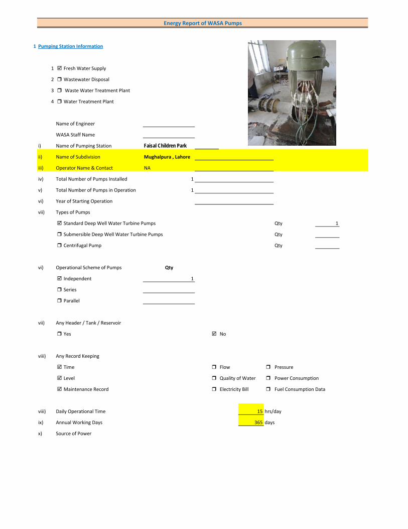
1 Pumping Station Information
1 Fresh Water Supply
2 Wastewater Disposal
3 Waste Water Treatment Plant
4 Water Treatment Plant
Name of Engineer
WASA Staff Name
i) Name of Pumping Station Faisal Children Park
ii) Name of Subdivision Mughalpura , Lahore
iii) Operator Name & Contact NA
iv) Total Number of Pumps Installed 1
v) Total Number of Pumps in Operation 1
vi) Year of Starting Operation
vii) Types of Pumps
Standard Deep Well Water Turbine Pumps Qty 1
Submersible Deep Well Water Turbine Pumps Qty
Centrifugal Pump Qty
vi) Operational Scheme of Pumps Qty
Independent 1
Series
Parallel
vii) Any Header / Tank / Reservoir
Yes No
viii) Any Record Keeping
Time Flow Pressure
Level Quality of Water Power Consumption
Maintenance Record Electricity Bill Fuel Consumption Data
viii) Daily Operational Time 15 hrs/day
ix) Annual Working Days 365 days
x) Source of Power
Energy Report of WASA Pumps

Primary LESCO Secondary
xi) In Case of Secondary Power Source Fuel Data Details
xii) Operational Hours of Secondary Power Source hrs/day
xiii) Availability of Chlorinator
Yes Not Working No
2 Pump Basic Information (Pump Ref # CITY_FWPS/WWDS_Pump #)
i) Type of Pump Deep Well
Submersible
Overhung
Between Bearing
ii) Mounting / Erection
Horizontal Vertical
Foundation
iii) Concrete Bolted Bolted
iv) Lubrication Type
Oil Water
v) Cooling Type
Water Cooled Air Cooled
vi) Number of Stages
Single Multi 5
vii) Pump and Motor Assembly
Direct Coupled Belt / Gear
viii) Source of Suction
Ground Water Aquafier Overhead Tank Underground Tank
Pressurized Source
ix) Pump Discharge Destination
Overhead Tank Drain On Ground Reservoir
Fresh Water Supply Network
Pump Operational Scheme
On / OFF Proportional
x) Pump Flow Control
Throttle VFD Controlled
xi) Any Retrofits ?
Impeller Detail
Casing / Volute Detail
Line Shaft (DW) Detail
Column Sett. (DW) Detail

Motor Replacement Detail
Motor Rewinding Detail
xii) Self Priming
Yes No NA (not applicable)
xiii) Non Clogging (In case of wastewater)
Yes No
xiv) Flowmeter Available
Yes No
xv) Flowmeter Working
Working Properly Malfunctioning (Damaged)
3 Pump Nameplate Data
i) Make / Brand KSB Pumps Country Pakistan
ii) Model B. 12 B/5 Serial 21/06/10
iii) Certification Mark
iv) Year of Manufacture 2006
v) Flowrate (Q) 2 Cusec 204 m3/hr
vi) Head (H) 220 ft
vii) Discharge Pressure (P) Psig
viii) Power / HP / BHP 62.93 BHP
ix) Speed (n) 1,450 RPM
x) Maximum Pressure (Pmax)
xi) Maxiumum Allowable Temperature
5 Piping System
Suction Side
Select Pipe Material of Construction MS Pipe
i) Enter Diameter of Suction Pipe (In) (Not Valid incase of Tubewells)
ii) Enter Length of Suction Pipe (ft) (Not Valid incase of Tubewells)
iii) Enter Fittings on Suction Pipe (Not Valid incase of Tubewells)
Fitting Type 1 Qty Type 2 Qty Type 3 Qty
Valves Foot Valve 1
Bends
Strainer 1
iv) Storage Capacity of Suction Source (Aquafier)
v) Working Volume of Source
vi) Suction Lift (from Datum Line)
viii) Availbility of Pressure Gauge Yes No
ix) Suction Pressure (Not Valid incase of Tubewells)
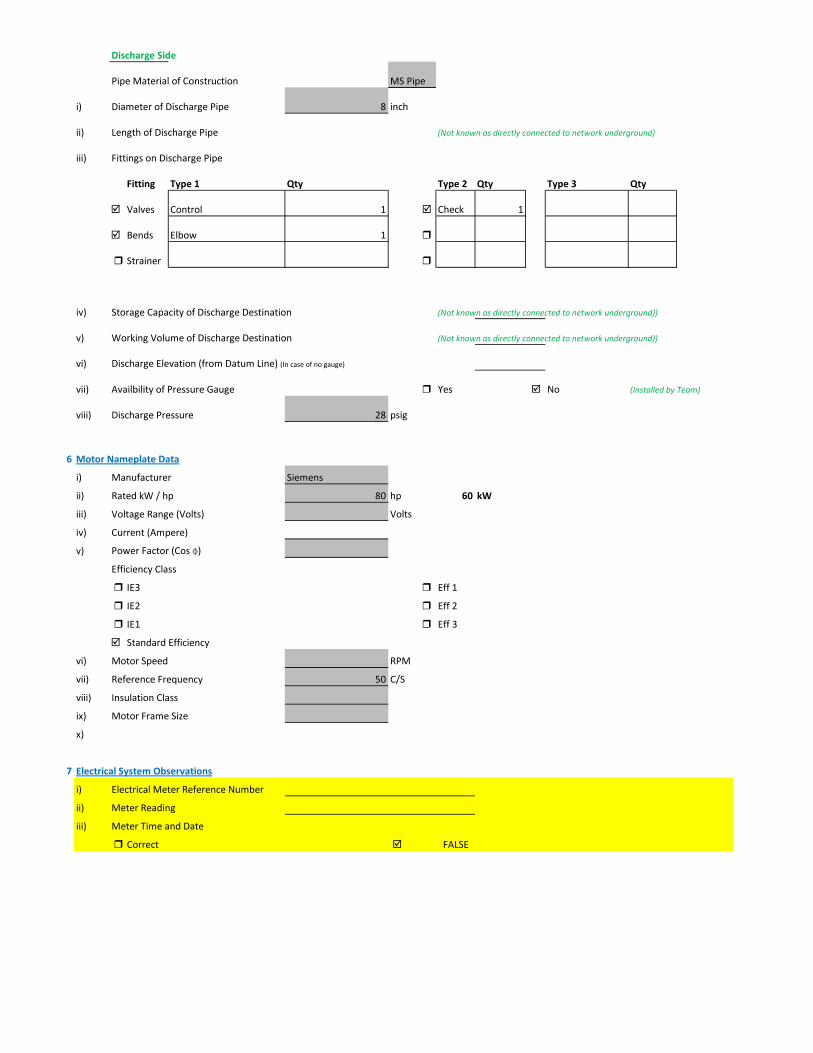
Discharge Side
Pipe Material of Construction MS Pipe
i) Diameter of Discharge Pipe 8 inch
ii) Length of Discharge Pipe (Not known as directly connected to network underground)
iii) Fittings on Discharge Pipe
Fitting Type 1 Qty Type 2 Qty Type 3 Qty
Valves Control 1 Check 1
Bends Elbow 1
Strainer
iv) Storage Capacity of Discharge Destination (Not known as directly connected to network underground))
v) Working Volume of Discharge Destination (Not known as directly connected to network underground))
vi) Discharge Elevation (from Datum Line) (In case of no gauge)
vii) Availbility of Pressure Gauge Yes No (Installed by Team)
viii) Discharge Pressure 28 psig
6 Motor Nameplate Data
i) Manufacturer Siemens
ii) Rated kW / hp 80 hp 60 kW
iii) Voltage Range (Volts) Volts
iv) Current (Ampere)
v) Power Factor (Cos ɸ)
Efficiency Class
IE3 Eff 1
IE2 Eff 2
IE1 Eff 3
Standard Efficiency
vi) Motor Speed RPM
vii) Reference Frequency 50 C/S
viii) Insulation Class
ix) Motor Frame Size
x)
7 Electrical System Observations
i) Electrical Meter Reference Number
ii) Meter Reading
iii) Meter Time and Date
Correct FALSE
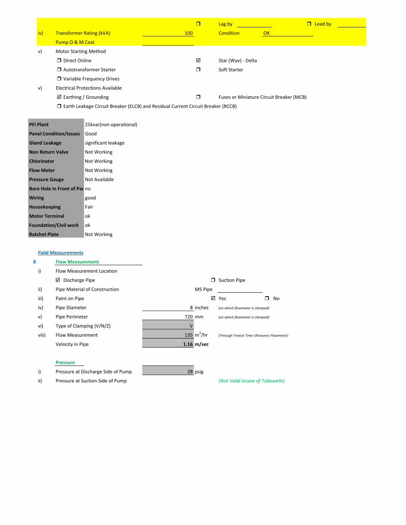
Lag by Lead by
iv) Transformer Rating (kVA) 100 Condition OK
Pump O & M Cost
v) Motor Starting Method
Direct Online Star (Wye) - Delta
Autotransformer Starter Soft Starter
Variable Frequency Drives
v) Electrical Protections Available
Earthing / Grounding Fuses or Miniature Circuit Breaker (MCB)
Earth Leakage Circuit Breaker (ELCB) and Residual Current Circuit Breaker (RCCB)
PFI Plant 25kvar(non operational)
Panel Condition/Issues Good
Gland Leakage significant leakage
Non Return Valve Not Working
Chlorinator Not Working
Flow Meter Not Working
Pressure Gauge Not Available
Bore Hole in Front of Panno
Wiring good
Housekeeping Fair
Motor Terminal ok
Foundation/Civil work ok
Ratchet Plate Not Working
Field Measurements
8 Flow Measurement
i) Flow Measurement Location
Discharge Pipe Suction Pipe
ii) Pipe Material of Construction MS Pipe
iii) Paint on Pipe Yes No
iv) Pipe Diameter 8 inches (on which flowmeter is clamped)
v) Pipe Perimeter 720 mm (on which flowmeter is clamped)
vi) Type of Clamping (V/N/Z) V
viii) Flow Measurement 135 m3/hr (Through Transit Time Ultrasonic Flowmeter)
Velocity in Pipe 1.16 m/sec
Pressure
i) Pressure at Discharge Side of Pump 28 psig
ii) Pressure at Suction Side of Pump (Not Valid incase of Tubewells)

iii) Water Shutoff Head
Levels
i) Static Water Level 38 meter Estimated
ii) Pumping Water Level 43 meter (estimated due to gland leakage and catching of wire by suction)
Electric Measurements
i) Voltage 366.1 368.7 364.8
ii) Ampere 70.8 74.2 78.3
iii) Power Factor 0.84
iv) Appearant Power (kVA) 47.2
v) Running Power (kW) 39.6
vi) Reactive Power (kVAr) 25.6
vi) Motor Working on Loading Basis 66.1 %
Oversize Undersize Properly Sized
Speed
i) Speed of Motor RPM
ii) Speed of Pump Impeller RPM
Noise Level
Noise Level (db(A)) Avg. Max: 92.2
Thermal Imaging
i) Motor Motor Pump Coupling
Pump Volute Casing Pump Bearings
Electric Panels
Calculations
10
i) Drawdown of Pump (Pumping water level - Static Water Level) 16.4 ft
ii) Static Suction Head (Only for WW Pump) ft
iii) Suction Side Frictional Head (Only for WW Pump) ft
iv) Dynamic Suction Head (ii+iii) (Only for WW Pump) ft
v) Discharge Head (Pressure Gauge) 64.68 ft
vi) Discharge Side Frictional Head 3.52 ft
vii) Dynamic Discharge Head (v+vi) 68.20 ft
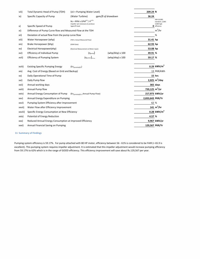
viii) Total Dynamic Head of Pump (TDH) (vii + Pumping Water Level) 209.24 ft
ix) Specific Capacity of Pump (Water Turbine) gpm/ft of drawdown 36.24
x) Specific Speed of Pump
Ns = RPM x GPM0.5 / H0.75
impeller rpm necessary to produce 1gpm/ft head 0
500-10,000, standard, 2,000-3,000 high efficiency
xi) Difference of Pump Curve flow and Measured Flow at the TDH m3/hr
xii) Deviation of actual flow from the pump curve flow %
xiii) Water Horsepower (whp) (TDH x Actual Measured Flow) 31.41 hp
xiv) Brake Horsepower (bhp) (OEM Data) 62.93 hp
xv) Electrical Horsepower(ehp) (Electrical Measurement at Motor input) 53.08 hp
xvi) Efficiency of Individual Pump (ηpump) (whp/bhp) x 100 49.91 %
xvii) Efficiency of Pumping System (ηsystem)Existing (whp/ehp) x 100 59.17 %
xviii) Existing Specific Pumping Energy (En(pumping01)) 0.29 kWh/m3
xix) Avg. Cost of Energy (Based on Grid and Backup) 13 PKR/kWh
xx) Daily Operational Time of Pump 15 hrs
xxi) Daily Pump flow 2,025 m3/day
xxii) Annual working days 365 days
xxiii) Annual Pump flow 739,125 m3/yr
xxiv) Annual Energy Consumption of Pump (En(pumping01) x Annual Pump Flow) 217,973 kWh/yr
xxv) Annual Energy Expenditure on Pumping 2,833,643 PKR/Yr
xxvi) Pumping System Efficiency after Improvement 62 %
xxvii) Water Flow after Efficiency Improvement 141 m3/hr
xxviii) Specific Energy Consumption at New Efficiency 0.28 kWh/m3
xxix) Potential of Energy Reduction 4.57 %
xxx) Reduced Annual Energy Consumption at Improved Efficiency 9,967 kWh/yr
xxxi) Annual Financial Saving on Pumping 129,567 PKR/Yr
11 Summary of Findings
Pumping system efficiency is 59.17%. For pump attached with 80 HP motor, efficiency between 56 - 61% is considered to be FAIR (> 65.9 is
excellent). This pumping system requires impeller adjustment. It is estimated that this impeller adjustment would increase pumping efficiency from 59.17% to 62% which is in the range of GOOD efficiency. This efficiency improvement will save about Rs.129,567 per year.
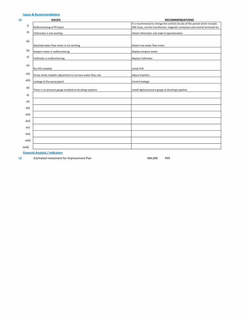
Issues & Recommendations
12 ISSUES RECOMMENDATIONS
i)
ii)
iii)
iv)
v)
vi)
vii)
viii)
ix)
x)
xi)
xii)
xiii)
xiv)
xv)
xvi)
xvii)
xviii)
Financial Analysis / Indicators
12 Estimated Investment for Improvement Plan 484,000 PKR
Replace Voltmeter Voltmeter is malfunctioning
Replace Ampere meterAmpere meter is malfunctioning
Chlorinator is not working Attach chlorinator and make it operationalize
Attached water flow meter is not working Attach new water flow meter
Malfunctioning of PFI plantIt is recommened to change the control circuity of the pannel which includes HRC fuses, current transformer, magnetic contactors and control terminals for
Control leakageLeakage at the pump gland
Install VFDNo VFD installed
Pump needs impeller adjustment to increase water flow rate Adjust impellers
There is no pressure gauge installed at discahrge pipeline Install digital pressure gauge at discahrge pipeline
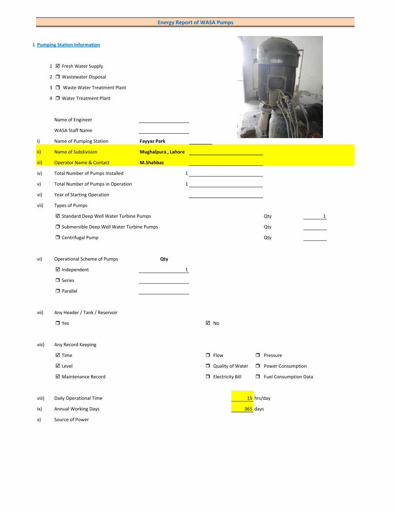
1 Pumping Station Information
1 Fresh Water Supply
2 Wastewater Disposal
3 Waste Water Treatment Plant
4 Water Treatment Plant
Name of Engineer
WASA Staff Name
i) Name of Pumping Station Fayyaz Park
ii) Name of Subdivision Mughalpura , Lahore
iii) Operator Name & Contact M.Shahbaz
iv) Total Number of Pumps Installed 1
v) Total Number of Pumps in Operation 1
vi) Year of Starting Operation
vii) Types of Pumps
Standard Deep Well Water Turbine Pumps Qty 1
Submersible Deep Well Water Turbine Pumps Qty
Centrifugal Pump Qty
vi) Operational Scheme of Pumps Qty
Independent 1
Series
Parallel
vii) Any Header / Tank / Reservoir
Yes No
viii) Any Record Keeping
Time Flow Pressure
Level Quality of Water Power Consumption
Maintenance Record Electricity Bill Fuel Consumption Data
viii) Daily Operational Time 15 hrs/day
ix) Annual Working Days 365 days
x) Source of Power
Energy Report of WASA Pumps

Primary LESCO Secondary
xi) In Case of Secondary Power Source Fuel Data Details
xii) Operational Hours of Secondary Power Source hrs/day
xiii) Availability of Chlorinator
Yes No
2 Pump Basic Information (Pump Ref # CITY_FWPS/WWDS_Pump #)
i) Type of Pump Deep Well
Submersible
Overhung
Between Bearing
ii) Mounting / Erection
Horizontal Vertical
Foundation
iii) Concrete Bolted Bolted
iv) Lubrication Type
Oil Water
v) Cooling Type
Water Cooled Air Cooled
vi) Number of Stages
Single Multi 4
vii) Pump and Motor Assembly
Direct Coupled Belt / Gear
viii) Source of Suction
Ground Water Aquafier Overhead Tank Underground Tank
Pressurized Source
ix) Pump Discharge Destination
Overhead Tank Drain On Ground Reservoir
Fresh Water Supply Network
Pump Operational Scheme
On / OFF Proportional
x) Pump Flow Control
Throttle VFD Controlled
xi) Any Retrofits ?
Impeller Detail
Casing / Volute Detail
Line Shaft (DW) Detail
Column Sett. (DW) Detail

Motor Replacement Detail
Motor Rewinding Detail
xii) Self Priming
Yes No NA (not applicable)
xiii) Non Clogging (In case of wastewater)
Yes No
xiv) Flowmeter Available
Yes No
xv) Flowmeter Working
Working Properly Malfunctioning (Damaged)
3 Pump Nameplate Data
i) Make / Brand KSB Pumps Country Pakistan
ii) Model B. 14 B/4 Serial 14-2835
iii) Certification Mark
iv) Year of Manufacture 2005
v) Flowrate (Q) 4 Cusec 408 m3/hr
vi) Head (H) 210 ft
vii) Discharge Pressure (P) Psig
viii) Power / HP / BHP 116.59 BHP
ix) Speed (n) 1,450 RPM
x) Maximum Pressure (Pmax)
xi) Maxiumum Allowable Temperature
5 Piping System
Suction Side
Select Pipe Material of Construction MS Pipe
i) Enter Diameter of Suction Pipe (In) (Not Valid incase of Tubewells)
ii) Enter Length of Suction Pipe (ft) (Not Valid incase of Tubewells)
iii) Enter Fittings on Suction Pipe (Not Valid incase of Tubewells)
Fitting Type 1 Qty Type 2 Qty Type 3 Qty
Valves Foot Valve 1
Bends
Strainer 1
iv) Storage Capacity of Suction Source (Aquafier)
v) Working Volume of Source
vi) Suction Lift (from Datum Line)
viii) Availbility of Pressure Gauge Not Working Yes No
ix) Suction Pressure (Not Valid incase of Tubewells)

Discharge Side
Pipe Material of Construction MS Pipe
i) Diameter of Discharge Pipe 10 inch
ii) Length of Discharge Pipe (Not known as directly connected to network underground)
iii) Fittings on Discharge Pipe
Fitting Type 1 Qty Type 2 Qty Type 3 Qty
Valves Control 1 Check 1
Bends Elbow 1
Strainer
iv) Storage Capacity of Discharge Destination (Not known as directly connected to network underground))
v) Working Volume of Discharge Destination (Not known as directly connected to network underground))
vi) Discharge Elevation (from Datum Line) (In case of no gauge)
vii) Availbility of Pressure Gauge Not Working Yes No (Installed by Team)
viii) Discharge Pressure 6 psig
6 Motor Nameplate Data
i) Manufacturer Siemens
ii) Rated kW / hp 150 hp 112.5 kW
iii) Voltage Range (Volts) 380 Volts
iv) Current (Ampere) 214
v) Power Factor (Cos ɸ) 0.85
Efficiency Class
IE3 Eff 1
IE2 Eff 2
IE1 Eff 3
Standard Efficiency
vi) Motor Speed 1,488 RPM
vii) Reference Frequency 50 C/S
viii) Insulation Class F
ix) Motor Frame Size 315 S
x)
7 Electrical System Observations
i) Electrical Meter Reference Number
ii) Meter Reading
iii) Meter Time and Date
Correct FALSE

Lag by Lead by
iv) Transformer Rating (kVA) 200 Condition OK
Pump O & M Cost
v) Motor Starting Method
Direct Online Star (Wye) - Delta
Autotransformer Starter Soft Starter
Variable Frequency Drives
v) Electrical Protections Available
Earthing / Grounding Fuses or Miniature Circuit Breaker (MCB)
Earth Leakage Circuit Breaker (ELCB) and Residual Current Circuit Breaker (RCCB)
PFI Plant Not installed
Panel Condition/Issues Very poor
Gland Leakage moderate leakage
Non Return Valve ok
Chlorinator Not Available
Flow Meter Not Available
Pressure Gauge Available(not working)
Bore Hole in Front of PanYes
Wiring poor
Housekeeping Fair
Motor Terminal
Foundation/Civil work ok
Ratchet Plate Not Working
Field Measurements
8 Flow Measurement
i) Flow Measurement Location
Discharge Pipe Suction Pipe
ii) Pipe Material of Construction MS Pipe
iii) Paint on Pipe Yes No
iv) Pipe Diameter 10 inches (on which flowmeter is clamped)
v) Pipe Perimeter 890 mm (on which flowmeter is clamped)
vi) Type of Clamping (V/N/Z) V
viii) Flow Measurement 200 m3/hr (Through Transit Time Ultrasonic Flowmeter)
Velocity in Pipe 1.10 m/sec
Pressure
i) Pressure at Discharge Side of Pump 6 psig
ii) Pressure at Suction Side of Pump (Not Valid incase of Tubewells)

iii) Water Shutoff Head
Levels
i) Static Water Level 38 meter Estimated
ii) Pumping Water Level 43 meter (estimated due to gland leakage and catching of wire by suction)
Electric Measurements
i) Voltage 385 379 379
ii) Ampere 127 123 122
iii) Power Factor 0.8
iv) Appearant Power (kVA) 81.7
v) Running Power (kW) 65.4
vi) Reactive Power (kVAr) 49
vi) Motor Working on Loading Basis 59.4 %
Oversize Undersize Properly Sized
Speed
i) Speed of Motor 1,488 RPM
ii) Speed of Pump Impeller 1,450 RPM
Noise Level
Noise Level (db(A)) Avg. Max: 90.3
Thermal Imaging
i) Motor Motor Pump Coupling
Pump Volute Casing Pump Bearings
Electric Panels
Calculations
10
i) Drawdown of Pump (Pumping water level - Static Water Level) 16.4 ft
ii) Static Suction Head (Only for WW Pump) ft
iii) Suction Side Frictional Head (Only for WW Pump) ft
iv) Dynamic Suction Head (ii+iii) (Only for WW Pump) ft
v) Discharge Head (Pressure Gauge) 13.86 ft
vi) Discharge Side Frictional Head 3.01 ft
vii) Dynamic Discharge Head (v+vi) 16.87 ft
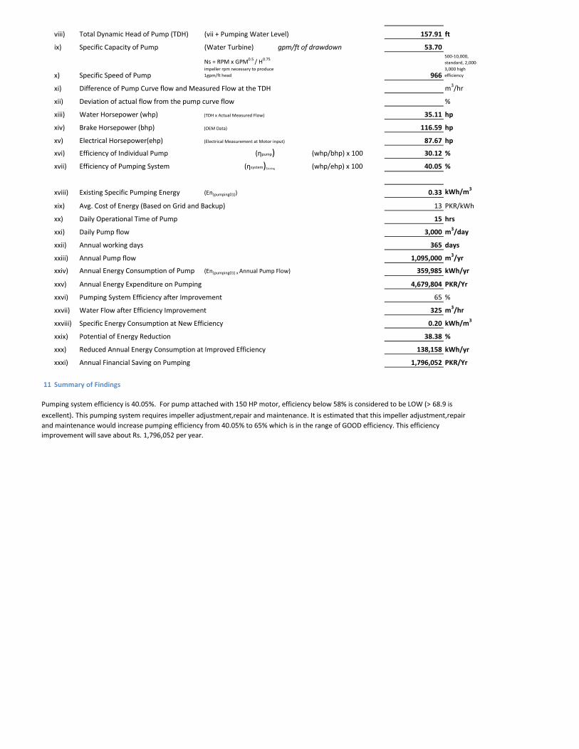
viii) Total Dynamic Head of Pump (TDH) (vii + Pumping Water Level) 157.91 ft
ix) Specific Capacity of Pump (Water Turbine) gpm/ft of drawdown 53.70
x) Specific Speed of Pump
Ns = RPM x GPM0.5 / H0.75
impeller rpm necessary to produce 1gpm/ft head 966
500-10,000, standard, 2,000-3,000 high efficiency
xi) Difference of Pump Curve flow and Measured Flow at the TDH m3/hr
xii) Deviation of actual flow from the pump curve flow %
xiii) Water Horsepower (whp) (TDH x Actual Measured Flow) 35.11 hp
xiv) Brake Horsepower (bhp) (OEM Data) 116.59 hp
xv) Electrical Horsepower(ehp) (Electrical Measurement at Motor input) 87.67 hp
xvi) Efficiency of Individual Pump (ηpump) (whp/bhp) x 100 30.12 %
xvii) Efficiency of Pumping System (ηsystem)Existing (whp/ehp) x 100 40.05 %
xviii) Existing Specific Pumping Energy (En(pumping01)) 0.33 kWh/m3
xix) Avg. Cost of Energy (Based on Grid and Backup) 13 PKR/kWh
xx) Daily Operational Time of Pump 15 hrs
xxi) Daily Pump flow 3,000 m3/day
xxii) Annual working days 365 days
xxiii) Annual Pump flow 1,095,000 m3/yr
xxiv) Annual Energy Consumption of Pump (En(pumping01) x Annual Pump Flow) 359,985 kWh/yr
xxv) Annual Energy Expenditure on Pumping 4,679,804 PKR/Yr
xxvi) Pumping System Efficiency after Improvement 65 %
xxvii) Water Flow after Efficiency Improvement 325 m3/hr
xxviii) Specific Energy Consumption at New Efficiency 0.20 kWh/m3
xxix) Potential of Energy Reduction 38.38 %
xxx) Reduced Annual Energy Consumption at Improved Efficiency 138,158 kWh/yr
xxxi) Annual Financial Saving on Pumping 1,796,052 PKR/Yr
11 Summary of Findings
Pumping system efficiency is 40.05%. For pump attached with 150 HP motor, efficiency below 58% is considered to be LOW (> 68.9 is
excellent). This pumping system requires impeller adjustment,repair and maintenance. It is estimated that this impeller adjustment,repair and maintenance would increase pumping efficiency from 40.05% to 65% which is in the range of GOOD efficiency. This efficiency improvement will save about Rs. 1,796,052 per year.
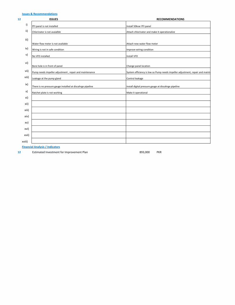
Issues & Recommendations
12 ISSUES RECOMMENDATIONS
i)
ii)
iii)
iv)
v)
vi)
vii)
viii)
ix)
x)
xi)
xii)
xiii)
xiv)
xv)
xvi)
xvii)
xviii)
Financial Analysis / Indicators
12 Estimated Investment for Improvement Plan 893,000 PKR
Install VFDNo VFD installed
Improve wiring conditionWiring is not in safe condition
Chlorinator is not avaialble Attach chlorinator and make it operationalize
Water flow meter is not available Attach new water flow meter
PFI panel is not installed Install 50kvar PFI panel
Control leakageLeakage at the pump gland
Change panel locationBore hole is in front of panel
Ratchet plate is not working Make it operational
Pump needs impeller adjustment , repair and maintenance System efficiency is low so Pump needs impeller adjustment, repair and mainte
There is no pressure gauge installed at discahrge pipeline Install digital pressure gauge at discahrge pipeline
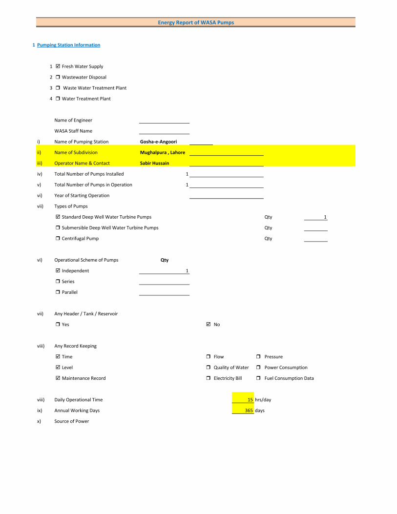
1 Pumping Station Information
1 Fresh Water Supply
2 Wastewater Disposal
3 Waste Water Treatment Plant
4 Water Treatment Plant
Name of Engineer
WASA Staff Name
i) Name of Pumping Station Gosha-e-Angoori
ii) Name of Subdivision Mughalpura , Lahore
iii) Operator Name & Contact Sabir Hussain
iv) Total Number of Pumps Installed 1
v) Total Number of Pumps in Operation 1
vi) Year of Starting Operation
vii) Types of Pumps
Standard Deep Well Water Turbine Pumps Qty 1
Submersible Deep Well Water Turbine Pumps Qty
Centrifugal Pump Qty
vi) Operational Scheme of Pumps Qty
Independent 1
Series
Parallel
vii) Any Header / Tank / Reservoir
Yes No
viii) Any Record Keeping
Time Flow Pressure
Level Quality of Water Power Consumption
Maintenance Record Electricity Bill Fuel Consumption Data
viii) Daily Operational Time 15 hrs/day
ix) Annual Working Days 365 days
x) Source of Power
Energy Report of WASA Pumps

Primary LESCO Secondary
xi) In Case of Secondary Power Source Fuel Data Details
xii) Operational Hours of Secondary Power Source hrs/day
xiii) Availability of Chlorinator
Yes Not Working No
2 Pump Basic Information (Pump Ref # CITY_FWPS/WWDS_Pump #)
i) Type of Pump Deep Well
Submersible
Overhung
Between Bearing
ii) Mounting / Erection
Horizontal Vertical
Foundation
iii) Concrete Bolted Bolted
iv) Lubrication Type
Oil Water
v) Cooling Type
Water Cooled Air Cooled
vi) Number of Stages
Single Multi 4
vii) Pump and Motor Assembly
Direct Coupled Belt / Gear
viii) Source of Suction
Ground Water Aquafier Overhead Tank Underground Tank
Pressurized Source
ix) Pump Discharge Destination
Overhead Tank Drain On Ground Reservoir
Fresh Water Supply Network
Pump Operational Scheme
On / OFF Proportional
x) Pump Flow Control
Throttle VFD Controlled
xi) Any Retrofits ?
Impeller Detail
Casing / Volute Detail
Line Shaft (DW) Detail
Column Sett. (DW) Detail

Motor Replacement Detail
Motor Rewinding Detail
xii) Self Priming
Yes No NA (not applicable)
xiii) Non Clogging (In case of wastewater)
Yes No
xiv) Flowmeter Available
Yes No
xv) Flowmeter Working
Working Properly Malfunctioning (Damaged)
3 Pump Nameplate Data
i) Make / Brand KSB Pumps Country Pakistan
ii) Model B. 14 B/4 Serial 21-05-10-4332
iii) Certification Mark
iv) Year of Manufacture 2006
v) Flowrate (Q) 4 Cusec 408 m3/hr
vi) Head (H) 220 ft
vii) Discharge Pressure (P) Psig
viii) Power / HP / BHP 122.63 BHP
ix) Speed (n) 1,485 RPM
x) Maximum Pressure (Pmax)
xi) Maxiumum Allowable Temperature
5 Piping System
Suction Side
Select Pipe Material of Construction MS Pipe
i) Enter Diameter of Suction Pipe (In) (Not Valid incase of Tubewells)
ii) Enter Length of Suction Pipe (ft) (Not Valid incase of Tubewells)
iii) Enter Fittings on Suction Pipe (Not Valid incase of Tubewells)
Fitting Type 1 Qty Type 2 Qty Type 3 Qty
Valves Foot Valve 1
Bends
Strainer 1
iv) Storage Capacity of Suction Source (Aquafier)
v) Working Volume of Source
vi) Suction Lift (from Datum Line)
viii) Availbility of Pressure Gauge Not Working Yes No
ix) Suction Pressure (Not Valid incase of Tubewells)

Discharge Side
Pipe Material of Construction MS Pipe
i) Diameter of Discharge Pipe 10 inch
ii) Length of Discharge Pipe (Not known as directly connected to network underground)
iii) Fittings on Discharge Pipe
Fitting Type 1 Qty Type 2 Qty Type 3 Qty
Valves Control 1 Check 1
Bends Elbow 1
Strainer
iv) Storage Capacity of Discharge Destination (Not known as directly connected to network underground))
v) Working Volume of Discharge Destination (Not known as directly connected to network underground))
vi) Discharge Elevation (from Datum Line) (In case of no gauge)
vii) Availbility of Pressure Gauge Not Working Yes No (Installed by Team)
viii) Discharge Pressure 10 psig
6 Motor Nameplate Data
i) Manufacturer Siemens
ii) Rated kW / hp 150 hp 112.5 kW
iii) Voltage Range (Volts) 380 Volts
iv) Current (Ampere) 214
v) Power Factor (Cos ɸ) 0.85
Efficiency Class
IE3 Eff 1
IE2 Eff 2
IE1 Eff 3
Standard Efficiency
vi) Motor Speed 1,488 RPM
vii) Reference Frequency 50 C/S
viii) Insulation Class F
ix) Motor Frame Size 315 S
x)
7 Electrical System Observations
i) Electrical Meter Reference Number
ii) Meter Reading
iii) Meter Time and Date
Correct FALSE

Lag by Lead by
iv) Transformer Rating (kVA) 200 Condition OK
Pump O & M Cost
v) Motor Starting Method
Direct Online Star (Wye) - Delta
Autotransformer Starter Soft Starter
Variable Frequency Drives
v) Electrical Protections Available
Earthing / Grounding Fuses or Miniature Circuit Breaker (MCB)
Earth Leakage Circuit Breaker (ELCB) and Residual Current Circuit Breaker (RCCB)
PFI Plant 50kvar(only 12.5kvar is operational)
Panel Condition/Issues Fair
Gland Leakage significant leakage
Non Return Valve ok
Chlorinator Available(not working)
Flow Meter Available(not working)
Pressure Gauge Available(not working)
Bore Hole in Front of PanYes
Wiring Fair
Housekeeping Fair
Motor Terminal
Foundation/Civil work ok
Ratchet Plate Not Working
Field Measurements
8 Flow Measurement
i) Flow Measurement Location
Discharge Pipe Suction Pipe
ii) Pipe Material of Construction MS Pipe
iii) Paint on Pipe Yes No
iv) Pipe Diameter 10 inches (on which flowmeter is clamped)
v) Pipe Perimeter 880 mm (on which flowmeter is clamped)
vi) Type of Clamping (V/N/Z) V
viii) Flow Measurement 300 m3/hr (Through Transit Time Ultrasonic Flowmeter)
Velocity in Pipe 1.64 m/sec
Pressure
i) Pressure at Discharge Side of Pump 10 psig
ii) Pressure at Suction Side of Pump (Not Valid incase of Tubewells)

iii) Water Shutoff Head
Levels
i) Static Water Level 38 meter Estimated
ii) Pumping Water Level 43 meter (estimated due to gland leakage and catching of wire by suction)
Electric Measurements
i) Voltage 370.6 371.2 374.9
ii) Ampere 154 153.6 148.2
iii) Power Factor 0.78
iv) Appearant Power (kVA) 97.8
v) Running Power (kW) 76.3
vi) Reactive Power (kVAr) 61.2
vi) Motor Working on Loading Basis 69.4 %
Oversize Undersize Properly Sized
Speed
i) Speed of Motor 1,488 RPM
ii) Speed of Pump Impeller 1,485 RPM
Noise Level
Noise Level (db(A)) Avg. Max:
Thermal Imaging
i) Motor Motor Pump Coupling
Pump Volute Casing Pump Bearings
Electric Panels
Calculations
10
i) Drawdown of Pump (Pumping water level - Static Water Level) 16.4 ft
ii) Static Suction Head (Only for WW Pump) ft
iii) Suction Side Frictional Head (Only for WW Pump) ft
iv) Dynamic Suction Head (ii+iii) (Only for WW Pump) ft
v) Discharge Head (Pressure Gauge) 23.1 ft
vi) Discharge Side Frictional Head 6.69 ft
vii) Dynamic Discharge Head (v+vi) 29.79 ft

viii) Total Dynamic Head of Pump (TDH) (vii + Pumping Water Level) 170.83 ft
ix) Specific Capacity of Pump (Water Turbine) gpm/ft of drawdown 80.54
x) Specific Speed of Pump
Ns = RPM x GPM0.5 / H0.75
impeller rpm necessary to produce 1gpm/ft head 1,142
500-10,000, standard, 2,000-3,000 high efficiency
xi) Difference of Pump Curve flow and Measured Flow at the TDH m3/hr
xii) Deviation of actual flow from the pump curve flow %
xiii) Water Horsepower (whp) (TDH x Actual Measured Flow) 56.98 hp
xiv) Brake Horsepower (bhp) (OEM Data) 122.63 hp
xv) Electrical Horsepower(ehp) (Electrical Measurement at Motor input) 102.28 hp
xvi) Efficiency of Individual Pump (ηpump) (whp/bhp) x 100 46.47 %
xvii) Efficiency of Pumping System (ηsystem)Existing (whp/ehp) x 100 55.71 %
xviii) Existing Specific Pumping Energy (En(pumping01)) 0.26 kWh/m3
xix) Avg. Cost of Energy (Based on Grid and Backup) 13 PKR/kWh
xx) Daily Operational Time of Pump 15 hrs
xxi) Daily Pump flow 4,500 m3/day
xxii) Annual working days 365 days
xxiii) Annual Pump flow 1,642,500 m3/yr
xxiv) Annual Energy Consumption of Pump (En(pumping01) x Annual Pump Flow) 419,982 kWh/yr
xxv) Annual Energy Expenditure on Pumping 5,459,771 PKR/Yr
xxvi) Pumping System Efficiency after Improvement 65 %
xxvii) Water Flow after Efficiency Improvement 350 m3/hr
xxviii) Specific Energy Consumption at New Efficiency 0.22 kWh/m3
xxix) Potential of Energy Reduction 14.29 %
xxx) Reduced Annual Energy Consumption at Improved Efficiency 60,003 kWh/yr
xxxi) Annual Financial Saving on Pumping 780,033 PKR/Yr
11 Summary of Findings
Pumping system efficiency is 55.71%. For pump attached with 150 HP motor, efficiency below 58% is considered to be LOW (> 68.9 is
excellent). This pumping system requires impeller adjustment. It is estimated that this impeller adjustment would increase pumping efficiency from 55.71% to 65% which is in the range of GOOD efficiency. This efficiency improvement will save about Rs. 780,033 per year. .

Issues & Recommendations
12 ISSUES RECOMMENDATIONS
i)
ii)
iii)
iv)
v)
vi)
vii)
viii)
ix)
x)
xi)
xii)
xiii)
xiv)
xv)
xvi)
xvii)
xviii)
Financial Analysis / Indicators
12 Estimated Investment for Improvement Plan 783,500 PKR
Replace Ampere meterAmpere meter is malfunctioning
Install VFDNo VFD installed
Chlorinator is not working Attach chlorinator and make it operationalize
Attached water flow meter is not working Attach new water flow meter
Malfunctioning of PFI plantIt is recommened to change the control circuity of the pannel which includes HRC fuses, current transformer, magnetic contactors and control terminals
Control leakageLeakage at the pump gland
Change panel locationBore is in front of panel
Ratchet plate is not working Make it operational
Pump needs impeller adjustment to increase water flow rate Adjust impellers
There is no digital pressure gauge installed at discahrge pipeline Install digital pressure gauge at discahrge pipeline
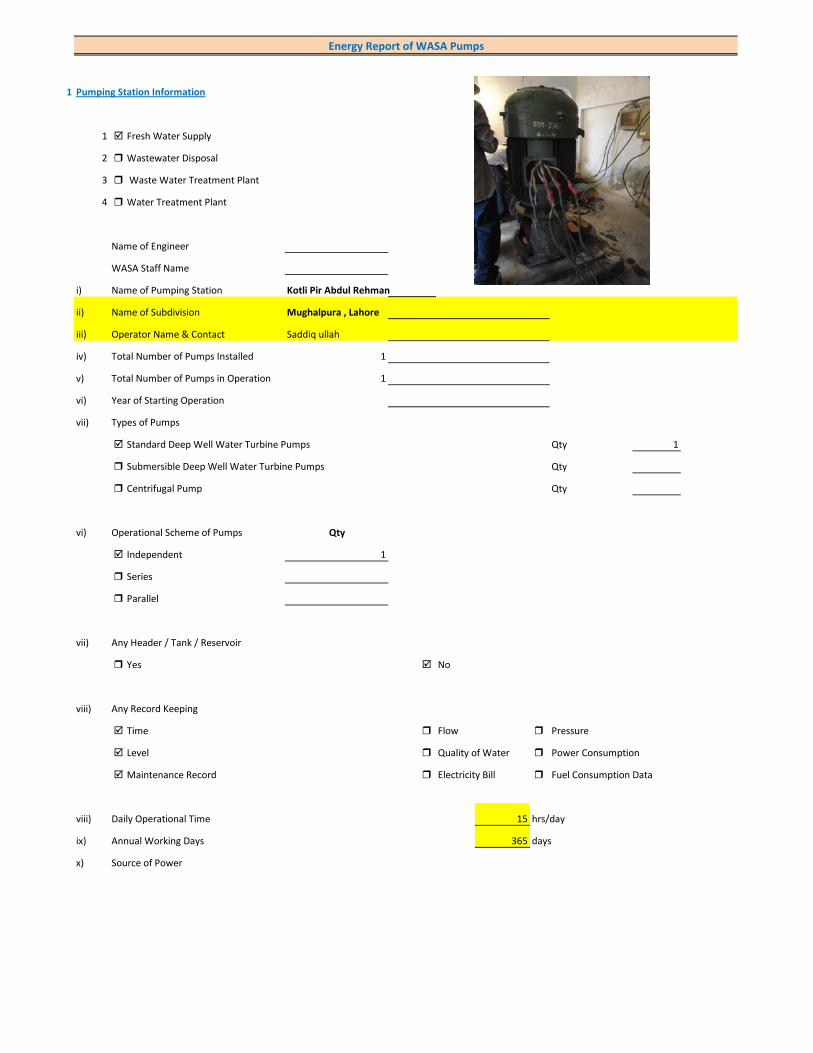
1 Pumping Station Information
1 Fresh Water Supply
2 Wastewater Disposal
3 Waste Water Treatment Plant
4 Water Treatment Plant
Name of Engineer
WASA Staff Name
i) Name of Pumping Station Kotli Pir Abdul Rehman
ii) Name of Subdivision Mughalpura , Lahore
iii) Operator Name & Contact Saddiq ullah
iv) Total Number of Pumps Installed 1
v) Total Number of Pumps in Operation 1
vi) Year of Starting Operation
vii) Types of Pumps
Standard Deep Well Water Turbine Pumps Qty 1
Submersible Deep Well Water Turbine Pumps Qty
Centrifugal Pump Qty
vi) Operational Scheme of Pumps Qty
Independent 1
Series
Parallel
vii) Any Header / Tank / Reservoir
Yes No
viii) Any Record Keeping
Time Flow Pressure
Level Quality of Water Power Consumption
Maintenance Record Electricity Bill Fuel Consumption Data
viii) Daily Operational Time 15 hrs/day
ix) Annual Working Days 365 days
x) Source of Power
Energy Report of WASA Pumps

Primary LESCO Secondary
xi) In Case of Secondary Power Source Fuel Data Details
xii) Operational Hours of Secondary Power Source hrs/day
xiii) Availability of Chlorinator
Yes No
2 Pump Basic Information (Pump Ref # CITY_FWPS/WWDS_Pump #)
i) Type of Pump Deep Well
Submersible
Overhung
Between Bearing
ii) Mounting / Erection
Horizontal Vertical
Foundation
iii) Concrete Bolted Bolted
iv) Lubrication Type
Oil Water
v) Cooling Type
Water Cooled Air Cooled
vi) Number of Stages
Single Multi 4
vii) Pump and Motor Assembly
Direct Coupled Belt / Gear
viii) Source of Suction
Ground Water Aquafier Overhead Tank Underground Tank
Pressurized Source
ix) Pump Discharge Destination
Overhead Tank Drain On Ground Reservoir
Fresh Water Supply Network
Pump Operational Scheme
On / OFF Proportional
x) Pump Flow Control
Throttle VFD Controlled
xi) Any Retrofits ?
Impeller Detail
Casing / Volute Detail
Line Shaft (DW) Detail
Column Sett. (DW) Detail

Motor Replacement Detail
Motor Rewinding Detail
xii) Self Priming
Yes No NA (not applicable)
xiii) Non Clogging (In case of wastewater)
Yes No
xiv) Flowmeter Available
Yes No
xv) Flowmeter Working
Working Properly Malfunctioning (Damaged)
3 Pump Nameplate Data
i) Make / Brand Country
ii) Model Serial
iii) Certification Mark
iv) Year of Manufacture
v) Flowrate (Q) 4 Cusec 408 m3/hr
vi) Head (H) ft
vii) Discharge Pressure (P) Psig
viii) Power / HP / BHP BHP
ix) Speed (n) RPM
x) Maximum Pressure (Pmax)
xi) Maxiumum Allowable Temperature
5 Piping System
Suction Side
Select Pipe Material of Construction MS Pipe
i) Enter Diameter of Suction Pipe (In) (Not Valid incase of Tubewells)
ii) Enter Length of Suction Pipe (ft) (Not Valid incase of Tubewells)
iii) Enter Fittings on Suction Pipe (Not Valid incase of Tubewells)
Fitting Type 1 Qty Type 2 Qty Type 3 Qty
Valves Foot Valve 1
Bends
Strainer 1
iv) Storage Capacity of Suction Source (Aquafier)
v) Working Volume of Source
vi) Suction Lift (from Datum Line)
viii) Availbility of Pressure Gauge Yes No
ix) Suction Pressure (Not Valid incase of Tubewells)
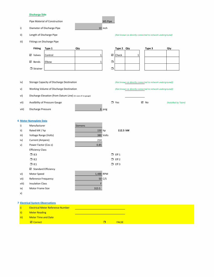
Discharge Side
Pipe Material of Construction MS Pipe
i) Diameter of Discharge Pipe 10 inch
ii) Length of Discharge Pipe (Not known as directly connected to network underground)
iii) Fittings on Discharge Pipe
Fitting Type 1 Qty Type 2 Qty Type 3 Qty
Valves Control 1 Check 1
Bends Elbow 1
Strainer
iv) Storage Capacity of Discharge Destination (Not known as directly connected to network underground))
v) Working Volume of Discharge Destination (Not known as directly connected to network underground))
vi) Discharge Elevation (from Datum Line) (In case of no gauge)
vii) Availbility of Pressure Gauge Yes No (Installed by Team)
viii) Discharge Pressure 6 psig
6 Motor Nameplate Data
i) Manufacturer Siemens
ii) Rated kW / hp 150 hp 112.5 kW
iii) Voltage Range (Volts) 380 Volts
iv) Current (Ampere) 214
v) Power Factor (Cos ɸ) 0.85
Efficiency Class
IE3 Eff 1
IE2 Eff 2
IE1 Eff 3
Standard Efficiency
vi) Motor Speed 1,488 RPM
vii) Reference Frequency 50 C/S
viii) Insulation Class F
ix) Motor Frame Size 315 S
x)
7 Electrical System Observations
i) Electrical Meter Reference Number
ii) Meter Reading
iii) Meter Time and Date
Correct FALSE
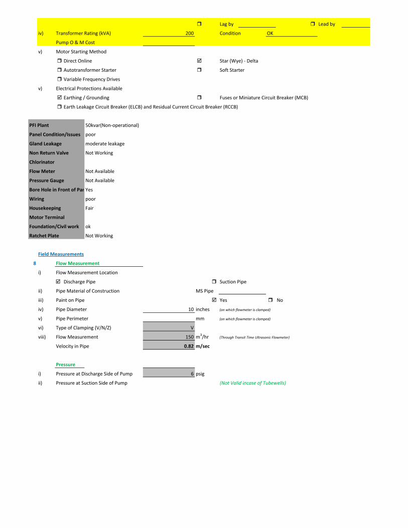
Lag by Lead by
iv) Transformer Rating (kVA) 200 Condition OK
Pump O & M Cost
v) Motor Starting Method
Direct Online Star (Wye) - Delta
Autotransformer Starter Soft Starter
Variable Frequency Drives
v) Electrical Protections Available
Earthing / Grounding Fuses or Miniature Circuit Breaker (MCB)
Earth Leakage Circuit Breaker (ELCB) and Residual Current Circuit Breaker (RCCB)
PFI Plant 50kvar(Non-operational)
Panel Condition/Issues poor
Gland Leakage moderate leakage
Non Return Valve Not Working
Chlorinator
Flow Meter Not Available
Pressure Gauge Not Available
Bore Hole in Front of PanYes
Wiring poor
Housekeeping Fair
Motor Terminal
Foundation/Civil work ok
Ratchet Plate Not Working
Field Measurements
8 Flow Measurement
i) Flow Measurement Location
Discharge Pipe Suction Pipe
ii) Pipe Material of Construction MS Pipe
iii) Paint on Pipe Yes No
iv) Pipe Diameter 10 inches (on which flowmeter is clamped)
v) Pipe Perimeter mm (on which flowmeter is clamped)
vi) Type of Clamping (V/N/Z) V
viii) Flow Measurement 150 m3/hr (Through Transit Time Ultrasonic Flowmeter)
Velocity in Pipe 0.82 m/sec
Pressure
i) Pressure at Discharge Side of Pump 6 psig
ii) Pressure at Suction Side of Pump (Not Valid incase of Tubewells)

iii) Water Shutoff Head
Levels
i) Static Water Level 38 meter Estimated
ii) Pumping Water Level 43 meter (estimated due to gland leakage and catching of wire by suction)
Electric Measurements
i) Voltage 355 357 358
ii) Ampere 185 178 180
iii) Power Factor 0.78
iv) Appearant Power (kVA) 111.7
v) Running Power (kW) 87.1
vi) Reactive Power (kVAr) 69.9
vi) Motor Working on Loading Basis 79.2 %
Oversize Undersize Properly Sized
Speed
i) Speed of Motor 1,488 RPM
ii) Speed of Pump Impeller RPM
Noise Level
Noise Level (db(A)) Avg. Max: 91
Thermal Imaging
i) Motor Motor Pump Coupling
Pump Volute Casing Pump Bearings
Electric Panels
Calculations
10
i) Drawdown of Pump (Pumping water level - Static Water Level) 16.4 ft
ii) Static Suction Head (Only for WW Pump) ft
iii) Suction Side Frictional Head (Only for WW Pump) ft
iv) Dynamic Suction Head (ii+iii) (Only for WW Pump) ft
v) Discharge Head (Pressure Gauge) 13.86 ft
vi) Discharge Side Frictional Head 1.70 ft
vii) Dynamic Discharge Head (v+vi) 15.56 ft

viii) Total Dynamic Head of Pump (TDH) (vii + Pumping Water Level) 156.60 ft
ix) Specific Capacity of Pump (Water Turbine) gpm/ft of drawdown 40.27
x) Specific Speed of Pump
Ns = RPM x GPM0.5 / H0.75
impeller rpm necessary to produce 1gpm/ft head 0
500-10,000, standard, 2,000-3,000 high efficiency
xi) Difference of Pump Curve flow and Measured Flow at the TDH m3/hr
xii) Deviation of actual flow from the pump curve flow %
xiii) Water Horsepower (whp) (TDH x Actual Measured Flow) 26.12 hp
xiv) Brake Horsepower (bhp) (OEM Data) 0 hp
xv) Electrical Horsepower(ehp) (Electrical Measurement at Motor input) 116.76 hp
xvi) Efficiency of Individual Pump (ηpump) (whp/bhp) x 100 #DIV/0! %
xvii) Efficiency of Pumping System (ηsystem)Existing (whp/ehp) x 100 22.37 %
xviii) Existing Specific Pumping Energy (En(pumping01)) 0.58 kWh/m3
xix) Avg. Cost of Energy (Based on Grid and Backup) 13 PKR/kWh
xx) Daily Operational Time of Pump 15 hrs
xxi) Daily Pump flow 2,250 m3/day
xxii) Annual working days 365 days
xxiii) Annual Pump flow 821,250 m3/yr
xxiv) Annual Energy Consumption of Pump (En(pumping01) x Annual Pump Flow) 479,429 kWh/yr
xxv) Annual Energy Expenditure on Pumping 6,232,583 PKR/Yr
xxvi) Pumping System Efficiency after Improvement 65 %
xxvii) Water Flow after Efficiency Improvement 436 m3/hr
xxviii) Specific Energy Consumption at New Efficiency 0.20 kWh/m3
xxix) Potential of Energy Reduction 65.58 %
xxx) Reduced Annual Energy Consumption at Improved Efficiency 314,431 kWh/yr
xxxi) Annual Financial Saving on Pumping 4,087,601 PKR/Yr
11 Summary of Findings
Pumping system efficiency is 22.37%. For pump attached with 150 HP motor, efficiency below 58% is considered to be LOW (> 68.9 is
excellent). This pump requires to change. It is estimated that this new pump would increase pumping efficiency from 22.37% to 65% which is in the range of GOOD efficiency. This efficiency improvement will save about Rs. 4,087,601 per year.

Issues & Recommendations
12 ISSUES RECOMMENDATIONS
i)
ii)
iii)
iv)
v)
vi)
vii)
viii)
ix)
x)
xi)
xii)
xiii)
xiv)
xv)
xvi)
xvii)
xviii)
Financial Analysis / Indicators
12 Estimated Investment for Improvement Plan 3,845,500 PKR
Control leakageLeakage at the pump gland
Make it operationalRatchet plate is not working
No VFD installed Install VFD
Pump needs to change Install new pump
Non return valve is not working Change Non return valve
There is no pressure gauge installed at discahrge pipeline Install digital pressure gauge at discahrge pipeline
Malfunctioning of PFI plantIt is recommened to change the control circuity of the pannel which includes HRC fuses, current transformer, magnetic contactors and control terminals for
Replace Ampere meterAmpere meter is malfunctioning
Improve wiring conditionWiring is not in safe condition
Bore hole is in front of panel Change panel location
Water flow meter is not working Attach new water flow meter
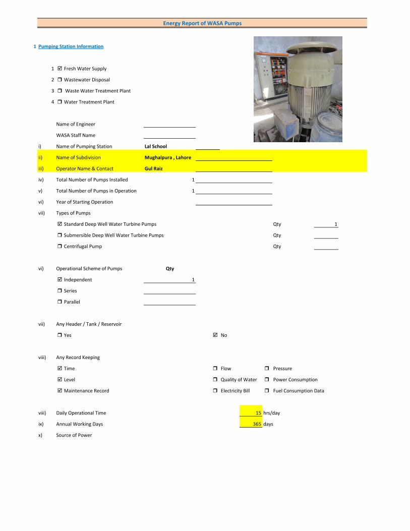
1 Pumping Station Information
1 Fresh Water Supply
2 Wastewater Disposal
3 Waste Water Treatment Plant
4 Water Treatment Plant
Name of Engineer
WASA Staff Name
i) Name of Pumping Station Lal School
ii) Name of Subdivision Mughalpura , Lahore
iii) Operator Name & Contact Gul Raiz
iv) Total Number of Pumps Installed 1
v) Total Number of Pumps in Operation 1
vi) Year of Starting Operation
vii) Types of Pumps
Standard Deep Well Water Turbine Pumps Qty 1
Submersible Deep Well Water Turbine Pumps Qty
Centrifugal Pump Qty
vi) Operational Scheme of Pumps Qty
Independent 1
Series
Parallel
vii) Any Header / Tank / Reservoir
Yes No
viii) Any Record Keeping
Time Flow Pressure
Level Quality of Water Power Consumption
Maintenance Record Electricity Bill Fuel Consumption Data
viii) Daily Operational Time 15 hrs/day
ix) Annual Working Days 365 days
x) Source of Power
Energy Report of WASA Pumps

Primary LESCO Secondary
xi) In Case of Secondary Power Source Fuel Data Details
xii) Operational Hours of Secondary Power Source hrs/day
xiii) Availability of Chlorinator
Yes No
2 Pump Basic Information (Pump Ref # CITY_FWPS/WWDS_Pump #)
i) Type of Pump Deep Well
Submersible
Overhung
Between Bearing
ii) Mounting / Erection
Horizontal Vertical
Foundation
iii) Concrete Bolted Bolted
iv) Lubrication Type
Oil Water
v) Cooling Type
Water Cooled Air Cooled
vi) Number of Stages
Single Multi 5
vii) Pump and Motor Assembly
Direct Coupled Belt / Gear
viii) Source of Suction
Ground Water Aquafier Overhead Tank Underground Tank
Pressurized Source
ix) Pump Discharge Destination
Overhead Tank Drain On Ground Reservoir
Fresh Water Supply Network
Pump Operational Scheme
On / OFF Proportional
x) Pump Flow Control
Throttle VFD Controlled
xi) Any Retrofits ?
Impeller Detail
Casing / Volute Detail
Line Shaft (DW) Detail
Column Sett. (DW) Detail

Motor Replacement Detail
Motor Rewinding Detail
xii) Self Priming
Yes No NA (not applicable)
xiii) Non Clogging (In case of wastewater)
Yes No
xiv) Flowmeter Available
Yes No
xv) Flowmeter Working
Working Properly Malfunctioning (Damaged)
3 Pump Nameplate Data
i) Make / Brand KSB Pumps Country Pakistan
ii) Model B. 12 B/5 Serial 9972143030/300/2
iii) Certification Mark
iv) Year of Manufacture 2012
v) Flowrate (Q) 2 Cusec 204 m3/hr
vi) Head (H) 210 ft
vii) Discharge Pressure (P) Psig
viii) Power / HP / BHP 59.72 BHP
ix) Speed (n) 1,450 RPM
x) Maximum Pressure (Pmax)
xi) Maxiumum Allowable Temperature
5 Piping System
Suction Side
Select Pipe Material of Construction MS Pipe
i) Enter Diameter of Suction Pipe (In) (Not Valid incase of Tubewells)
ii) Enter Length of Suction Pipe (ft) (Not Valid incase of Tubewells)
iii) Enter Fittings on Suction Pipe (Not Valid incase of Tubewells)
Fitting Type 1 Qty Type 2 Qty Type 3 Qty
Valves Foot Valve 1
Bends
Strainer 1
iv) Storage Capacity of Suction Source (Aquafier)
v) Working Volume of Source
vi) Suction Lift (from Datum Line)
viii) Availbility of Pressure Gauge Yes No
ix) Suction Pressure (Not Valid incase of Tubewells)

Discharge Side
Pipe Material of Construction MS Pipe
i) Diameter of Discharge Pipe 8 inch
ii) Length of Discharge Pipe (Not known as directly connected to network underground)
iii) Fittings on Discharge Pipe
Fitting Type 1 Qty Type 2 Qty Type 3 Qty
Valves Control 1 Check 1
Bends Elbow 1
Strainer
iv) Storage Capacity of Discharge Destination (Not known as directly connected to network underground))
v) Working Volume of Discharge Destination (Not known as directly connected to network underground))
vi) Discharge Elevation (from Datum Line) (In case of no gauge)
vii) Availbility of Pressure Gauge Yes No (Installed by Team)
viii) Discharge Pressure 8 psig
6 Motor Nameplate Data
i) Manufacturer Siemens
ii) Rated kW / hp 80 hp 60 kW
iii) Voltage Range (Volts) 380 Volts
iv) Current (Ampere) 115
v) Power Factor (Cos ɸ) 0.85
Efficiency Class
IE3 Eff 1
IE2 Eff 2
IE1 Eff 3
Standard Efficiency
vi) Motor Speed 1,488 RPM
vii) Reference Frequency 50 C/S
viii) Insulation Class F
ix) Motor Frame Size 250 M
x)
7 Electrical System Observations
i) Electrical Meter Reference Number
ii) Meter Reading
iii) Meter Time and Date
Correct FALSE
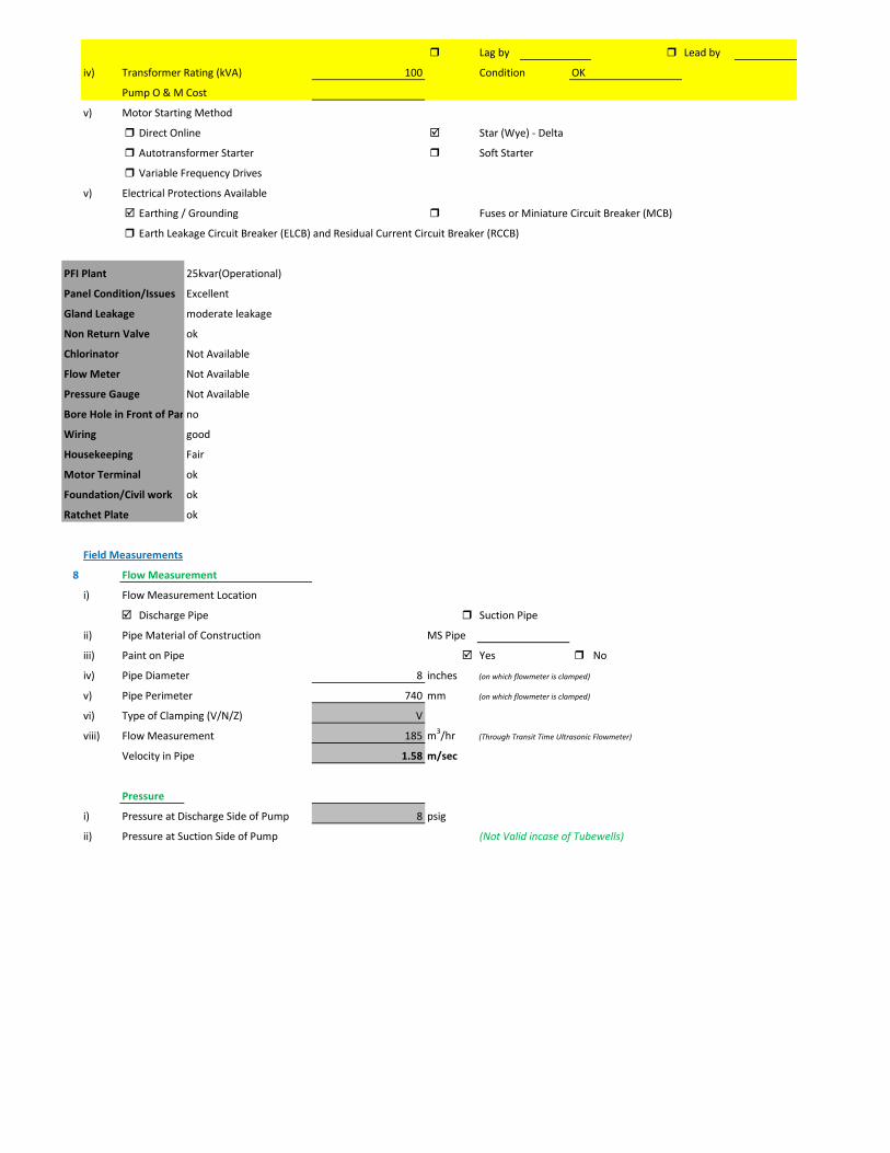
Lag by Lead by
iv) Transformer Rating (kVA) 100 Condition OK
Pump O & M Cost
v) Motor Starting Method
Direct Online Star (Wye) - Delta
Autotransformer Starter Soft Starter
Variable Frequency Drives
v) Electrical Protections Available
Earthing / Grounding Fuses or Miniature Circuit Breaker (MCB)
Earth Leakage Circuit Breaker (ELCB) and Residual Current Circuit Breaker (RCCB)
PFI Plant 25kvar(Operational)
Panel Condition/Issues Excellent
Gland Leakage moderate leakage
Non Return Valve ok
Chlorinator Not Available
Flow Meter Not Available
Pressure Gauge Not Available
Bore Hole in Front of Panno
Wiring good
Housekeeping Fair
Motor Terminal ok
Foundation/Civil work ok
Ratchet Plate ok
Field Measurements
8 Flow Measurement
i) Flow Measurement Location
Discharge Pipe Suction Pipe
ii) Pipe Material of Construction MS Pipe
iii) Paint on Pipe Yes No
iv) Pipe Diameter 8 inches (on which flowmeter is clamped)
v) Pipe Perimeter 740 mm (on which flowmeter is clamped)
vi) Type of Clamping (V/N/Z) V
viii) Flow Measurement 185 m3/hr (Through Transit Time Ultrasonic Flowmeter)
Velocity in Pipe 1.58 m/sec
Pressure
i) Pressure at Discharge Side of Pump 8 psig
ii) Pressure at Suction Side of Pump (Not Valid incase of Tubewells)

iii) Water Shutoff Head
Levels
i) Static Water Level 38 meter Estimated
ii) Pumping Water Level 43 meter (estimated due to gland leakage and catching of wire by suction)
Electric Measurements
i) Voltage 423.5 427 423
ii) Ampere 82.7 71 73.4
iii) Power Factor 0.82
iv) Appearant Power (kVA) 55.6
v) Running Power (kW) 45.6
vi) Reactive Power (kVAr) 31.8
vi) Motor Working on Loading Basis 76 %
Oversize Undersize Properly Sized
Speed
i) Speed of Motor 1,488 RPM
ii) Speed of Pump Impeller 1,450 RPM
Noise Level
Noise Level (db(A)) Avg. Max: 89
Thermal Imaging
i) Motor Motor Pump Coupling
Pump Volute Casing Pump Bearings
Electric Panels
Calculations
10
i) Drawdown of Pump (Pumping water level - Static Water Level) 16.4 ft
ii) Static Suction Head (Only for WW Pump) ft
iii) Suction Side Frictional Head (Only for WW Pump) ft
iv) Dynamic Suction Head (ii+iii) (Only for WW Pump) ft
v) Discharge Head (Pressure Gauge) 18.48 ft
vi) Discharge Side Frictional Head 6.53 ft
vii) Dynamic Discharge Head (v+vi) 25.01 ft

viii) Total Dynamic Head of Pump (TDH) (vii + Pumping Water Level) 166.05 ft
ix) Specific Capacity of Pump (Water Turbine) gpm/ft of drawdown 49.67
x) Specific Speed of Pump
Ns = RPM x GPM0.5 / H0.75
impeller rpm necessary to produce 1gpm/ft head 895
500-10,000, standard, 2,000-3,000 high efficiency
xi) Difference of Pump Curve flow and Measured Flow at the TDH m3/hr
xii) Deviation of actual flow from the pump curve flow %
xiii) Water Horsepower (whp) (TDH x Actual Measured Flow) 34.16 hp
xiv) Brake Horsepower (bhp) (OEM Data) 59.72 hp
xv) Electrical Horsepower(ehp) (Electrical Measurement at Motor input) 61.13 hp
xvi) Efficiency of Individual Pump (ηpump) (whp/bhp) x 100 57.19 %
xvii) Efficiency of Pumping System (ηsystem)Existing (whp/ehp) x 100 55.88 %
xviii) Existing Specific Pumping Energy (En(pumping01)) 0.25 kWh/m3
xix) Avg. Cost of Energy (Based on Grid and Backup) 13 PKR/kWh
xx) Daily Operational Time of Pump 15 hrs
xxi) Daily Pump flow 2,775 m3/day
xxii) Annual working days 365 days
xxiii) Annual Pump flow 1,012,875 m3/yr
xxiv) Annual Energy Consumption of Pump (En(pumping01) x Annual Pump Flow) 250,999 kWh/yr
xxv) Annual Energy Expenditure on Pumping 3,262,983 PKR/Yr
xxvi) Pumping System Efficiency after Improvement 62 %
xxvii) Water Flow after Efficiency Improvement 205 m3/hr
xxviii) Specific Energy Consumption at New Efficiency 0.22 kWh/m3
xxix) Potential of Energy Reduction 9.87 %
xxx) Reduced Annual Energy Consumption at Improved Efficiency 24,779 kWh/yr
xxxi) Annual Financial Saving on Pumping 322,128 PKR/Yr
11 Summary of Findings
Pumping system efficiency is 55.88%. For pump attached with 80 HP motor, efficiency below 56% is considered to be LOW (> 65.9 is
excellent). This pumping system requires impeller adjustment. It is estimated that this impeller adjustment would increase pumping efficiency from 55.88% to 62% which is in the range of GOOD efficiency. This efficiency improvement will save about Rs. 322,128 per year.
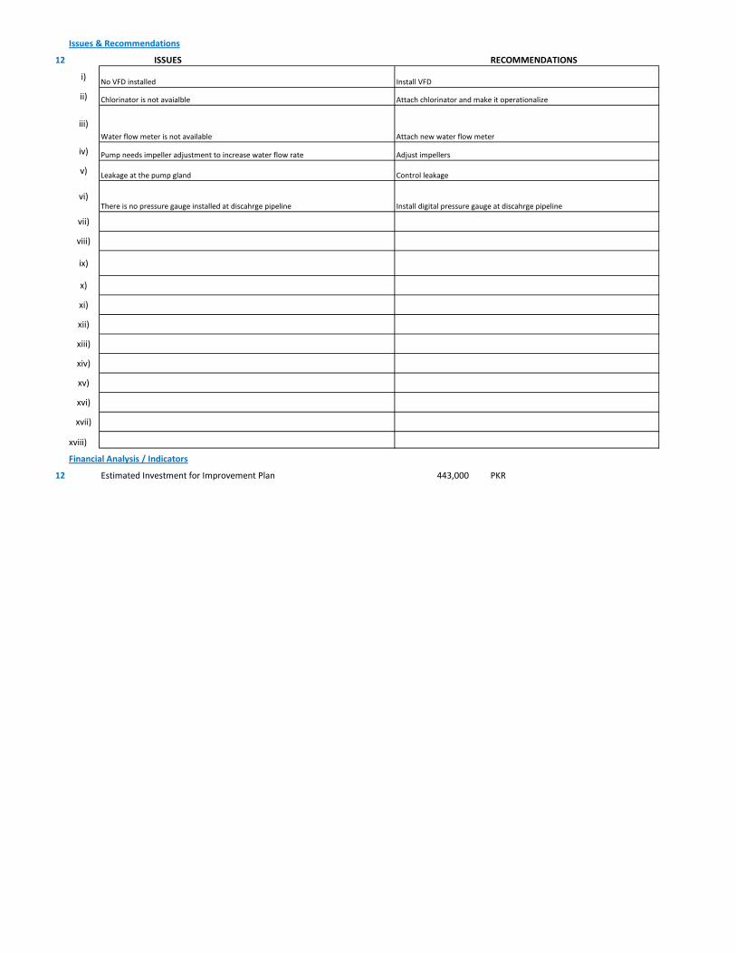
Issues & Recommendations
12 ISSUES RECOMMENDATIONS
i)
ii)
iii)
iv)
v)
vi)
vii)
viii)
ix)
x)
xi)
xii)
xiii)
xiv)
xv)
xvi)
xvii)
xviii)
Financial Analysis / Indicators
12 Estimated Investment for Improvement Plan 443,000 PKR
Control leakageLeakage at the pump gland
Adjust impellersPump needs impeller adjustment to increase water flow rate
Chlorinator is not avaialble Attach chlorinator and make it operationalize
Water flow meter is not available Attach new water flow meter
No VFD installed Install VFD
Install digital pressure gauge at discahrge pipelineThere is no pressure gauge installed at discahrge pipeline
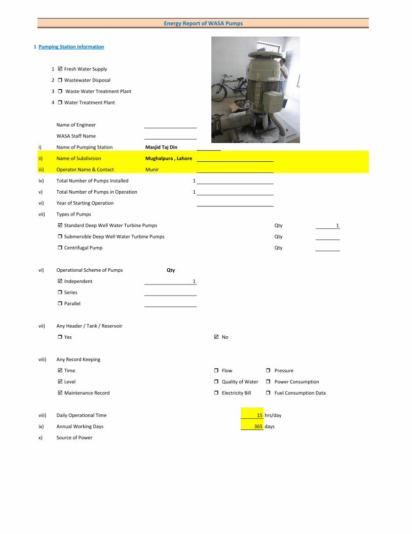
1 Pumping Station Information
1 Fresh Water Supply
2 Wastewater Disposal
3 Waste Water Treatment Plant
4 Water Treatment Plant
Name of Engineer
WASA Staff Name
i) Name of Pumping Station Masjid Taj Din
ii) Name of Subdivision Mughalpura , Lahore
iii) Operator Name & Contact Munir
iv) Total Number of Pumps Installed 1
v) Total Number of Pumps in Operation 1
vi) Year of Starting Operation
vii) Types of Pumps
Standard Deep Well Water Turbine Pumps Qty 1
Submersible Deep Well Water Turbine Pumps Qty
Centrifugal Pump Qty
vi) Operational Scheme of Pumps Qty
Independent 1
Series
Parallel
vii) Any Header / Tank / Reservoir
Yes No
viii) Any Record Keeping
Time Flow Pressure
Level Quality of Water Power Consumption
Maintenance Record Electricity Bill Fuel Consumption Data
viii) Daily Operational Time 15 hrs/day
ix) Annual Working Days 365 days
x) Source of Power
Energy Report of WASA Pumps

Primary LESCO Secondary
xi) In Case of Secondary Power Source Fuel Data Details
xii) Operational Hours of Secondary Power Source hrs/day
xiii) Availability of Chlorinator
Yes No
2 Pump Basic Information (Pump Ref # CITY_FWPS/WWDS_Pump #)
i) Type of Pump Deep Well
Submersible
Overhung
Between Bearing
ii) Mounting / Erection
Horizontal Vertical
Foundation
iii) Concrete Bolted Bolted
iv) Lubrication Type
Oil Water
v) Cooling Type
Water Cooled Air Cooled
vi) Number of Stages
Single Multi 5
vii) Pump and Motor Assembly
Direct Coupled Belt / Gear
viii) Source of Suction
Ground Water Aquafier Overhead Tank Underground Tank
Pressurized Source
ix) Pump Discharge Destination
Overhead Tank Drain On Ground Reservoir
Fresh Water Supply Network
Pump Operational Scheme
On / OFF Proportional
x) Pump Flow Control
Throttle VFD Controlled
xi) Any Retrofits ?
Impeller Detail
Casing / Volute Detail
Line Shaft (DW) Detail
Column Sett. (DW) Detail

Motor Replacement Detail
Motor Rewinding Detail
xii) Self Priming
Yes No NA (not applicable)
xiii) Non Clogging (In case of wastewater)
Yes No
xiv) Flowmeter Available
Yes No
xv) Flowmeter Working
Working Properly Malfunctioning (Damaged)
3 Pump Nameplate Data
i) Make / Brand KSB Pumps Country Pakistan
ii) Model B. 12 B/5 Serial 9972171833/300
iii) Certification Mark
iv) Year of Manufacture 2012
v) Flowrate (Q) 2 Cusec 204 m3/hr
vi) Head (H) 210 ft
vii) Discharge Pressure (P) Psig
viii) Power / HP / BHP 59.72 BHP
ix) Speed (n) 1,450 RPM
x) Maximum Pressure (Pmax)
xi) Maxiumum Allowable Temperature
5 Piping System
Suction Side
Select Pipe Material of Construction MS Pipe
i) Enter Diameter of Suction Pipe (In) (Not Valid incase of Tubewells)
ii) Enter Length of Suction Pipe (ft) (Not Valid incase of Tubewells)
iii) Enter Fittings on Suction Pipe (Not Valid incase of Tubewells)
Fitting Type 1 Qty Type 2 Qty Type 3 Qty
Valves Foot Valve 1
Bends
Strainer 1
iv) Storage Capacity of Suction Source (Aquafier)
v) Working Volume of Source
vi) Suction Lift (from Datum Line)
viii) Availbility of Pressure Gauge Not Working Yes No
ix) Suction Pressure (Not Valid incase of Tubewells)

Discharge Side
Pipe Material of Construction MS Pipe
i) Diameter of Discharge Pipe 8 inch
ii) Length of Discharge Pipe (Not known as directly connected to network underground)
iii) Fittings on Discharge Pipe
Fitting Type 1 Qty Type 2 Qty Type 3 Qty
Valves Control 1 Check 1
Bends Elbow 1
Strainer
iv) Storage Capacity of Discharge Destination (Not known as directly connected to network underground))
v) Working Volume of Discharge Destination (Not known as directly connected to network underground))
vi) Discharge Elevation (from Datum Line) (In case of no gauge)
vii) Availbility of Pressure Gauge Not Working Yes No (Installed by Team)
viii) Discharge Pressure 10 psig
6 Motor Nameplate Data
i) Manufacturer Siemens
ii) Rated kW / hp 80 hp 60 kW
iii) Voltage Range (Volts) 380 Volts
iv) Current (Ampere) 115
v) Power Factor (Cos ɸ) 0.85
Efficiency Class
IE3 Eff 1
IE2 Eff 2
IE1 Eff 3
Standard Efficiency
vi) Motor Speed 1,488 RPM
vii) Reference Frequency 50 C/S
viii) Insulation Class F
ix) Motor Frame Size 250 M
x)
7 Electrical System Observations
i) Electrical Meter Reference Number
ii) Meter Reading
iii) Meter Time and Date
Correct FALSE

Lag by Lead by
iv) Transformer Rating (kVA) 100 Condition OK
Pump O & M Cost
v) Motor Starting Method
Direct Online Star (Wye) - Delta
Autotransformer Starter Soft Starter
Variable Frequency Drives
v) Electrical Protections Available
Earthing / Grounding Fuses or Miniature Circuit Breaker (MCB)
Earth Leakage Circuit Breaker (ELCB) and Residual Current Circuit Breaker (RCCB)
PFI Plant 25kvar( operational)
Panel Condition/Issues Excellent
Gland Leakage Minor leakage
Non Return Valve ok
Chlorinator Not Available
Flow Meter Not Available
Pressure Gauge Available(not working)
Bore Hole in Front of Panno
Wiring Good
Housekeeping Fair
Motor Terminal
Foundation/Civil work ok
Ratchet Plate ok
Field Measurements
8 Flow Measurement
i) Flow Measurement Location
Discharge Pipe Suction Pipe
ii) Pipe Material of Construction MS Pipe
iii) Paint on Pipe Yes No
iv) Pipe Diameter 8 inches (on which flowmeter is clamped)
v) Pipe Perimeter 700 mm (on which flowmeter is clamped)
vi) Type of Clamping (V/N/Z) V
viii) Flow Measurement 100 m3/hr (Through Transit Time Ultrasonic Flowmeter)
Velocity in Pipe 0.86 m/sec
Pressure
i) Pressure at Discharge Side of Pump 10 psig
ii) Pressure at Suction Side of Pump (Not Valid incase of Tubewells)

iii) Water Shutoff Head
Levels
i) Static Water Level 38 meter Estimated
ii) Pumping Water Level 43 meter (estimated due to gland leakage and catching of wire by suction)
Electric Measurements
i) Voltage 407.2 399.7 399.9
ii) Ampere 66.4 73.1 68
iii) Power Factor 0.68
iv) Appearant Power (kVA) 48.1
v) Running Power (kW) 32.7
vi) Reactive Power (kVAr) 35.3
vi) Motor Working on Loading Basis 54.6 %
Oversize Undersize Properly Sized
Speed
i) Speed of Motor 1,488 RPM
ii) Speed of Pump Impeller 1,450 RPM
Noise Level
Noise Level (db(A)) Avg. Max: 88.6
Thermal Imaging
i) Motor Motor Pump Coupling
Pump Volute Casing Pump Bearings
Electric Panels
Calculations
10
i) Drawdown of Pump (Pumping water level - Static Water Level) 16.4 ft
ii) Static Suction Head (Only for WW Pump) ft
iii) Suction Side Frictional Head (Only for WW Pump) ft
iv) Dynamic Suction Head (ii+iii) (Only for WW Pump) ft
v) Discharge Head (Pressure Gauge) 23.1 ft
vi) Discharge Side Frictional Head 1.95 ft
vii) Dynamic Discharge Head (v+vi) 25.05 ft
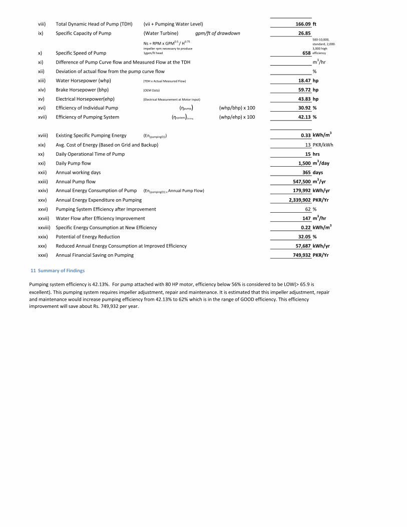
viii) Total Dynamic Head of Pump (TDH) (vii + Pumping Water Level) 166.09 ft
ix) Specific Capacity of Pump (Water Turbine) gpm/ft of drawdown 26.85
x) Specific Speed of Pump
Ns = RPM x GPM0.5 / H0.75
impeller rpm necessary to produce 1gpm/ft head 658
500-10,000, standard, 2,000-3,000 high efficiency
xi) Difference of Pump Curve flow and Measured Flow at the TDH m3/hr
xii) Deviation of actual flow from the pump curve flow %
xiii) Water Horsepower (whp) (TDH x Actual Measured Flow) 18.47 hp
xiv) Brake Horsepower (bhp) (OEM Data) 59.72 hp
xv) Electrical Horsepower(ehp) (Electrical Measurement at Motor input) 43.83 hp
xvi) Efficiency of Individual Pump (ηpump) (whp/bhp) x 100 30.92 %
xvii) Efficiency of Pumping System (ηsystem)Existing (whp/ehp) x 100 42.13 %
xviii) Existing Specific Pumping Energy (En(pumping01)) 0.33 kWh/m3
xix) Avg. Cost of Energy (Based on Grid and Backup) 13 PKR/kWh
xx) Daily Operational Time of Pump 15 hrs
xxi) Daily Pump flow 1,500 m3/day
xxii) Annual working days 365 days
xxiii) Annual Pump flow 547,500 m3/yr
xxiv) Annual Energy Consumption of Pump (En(pumping01) x Annual Pump Flow) 179,992 kWh/yr
xxv) Annual Energy Expenditure on Pumping 2,339,902 PKR/Yr
xxvi) Pumping System Efficiency after Improvement 62 %
xxvii) Water Flow after Efficiency Improvement 147 m3/hr
xxviii) Specific Energy Consumption at New Efficiency 0.22 kWh/m3
xxix) Potential of Energy Reduction 32.05 %
xxx) Reduced Annual Energy Consumption at Improved Efficiency 57,687 kWh/yr
xxxi) Annual Financial Saving on Pumping 749,932 PKR/Yr
11 Summary of Findings
Pumping system efficiency is 42.13%. For pump attached with 80 HP motor, efficiency below 56% is considered to be LOW(> 65.9 is
excellent). This pumping system requires impeller adjustment, repair and maintenance. It is estimated that this impeller adjustment, repair and maintenance would increase pumping efficiency from 42.13% to 62% which is in the range of GOOD efficiency. This efficiency improvement will save about Rs. 749,932 per year.
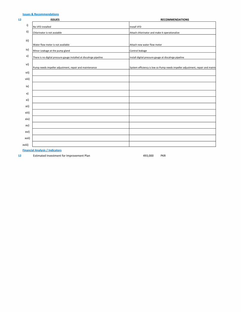
Issues & Recommendations
12 ISSUES RECOMMENDATIONS
i)
ii)
iii)
iv)
v)
vi)
vii)
viii)
ix)
x)
xi)
xii)
xiii)
xiv)
xv)
xvi)
xvii)
xviii)
Financial Analysis / Indicators
12 Estimated Investment for Improvement Plan 493,000 PKR
Install digital pressure gauge at discahrge pipelineThere is no digital pressure gauge installed at discahrge pipeline
Control leakageMinor Leakage at the pump gland
Chlorinator is not avaiable Attach chlorinator and make it operationalize
Water flow meter is not available Attach new water flow meter
No VFD installed Install VFD
System efficiency is low so Pump needs impeller adjustment, repair and mainte Pump needs impeller adjustment, repair and maintenance

1 Pumping Station Information
1 Fresh Water Supply
2 Wastewater Disposal
3 Waste Water Treatment Plant
4 Water Treatment Plant
Name of Engineer
WASA Staff Name
i) Name of Pumping Station Mushtaq Colony
ii) Name of Subdivision Mughalpura , Lahore
iii) Operator Name & Contact M.Nabeel
iv) Total Number of Pumps Installed 1
v) Total Number of Pumps in Operation 1
vi) Year of Starting Operation
vii) Types of Pumps
Standard Deep Well Water Turbine Pumps Qty 1
Submersible Deep Well Water Turbine Pumps Qty
Centrifugal Pump Qty
vi) Operational Scheme of Pumps Qty
Independent 1
Series
Parallel
vii) Any Header / Tank / Reservoir
Yes No
viii) Any Record Keeping
Time Flow Pressure
Level Quality of Water Power Consumption
Maintenance Record Electricity Bill Fuel Consumption Data
viii) Daily Operational Time 15 hrs/day
ix) Annual Working Days 365 days
x) Source of Power
Energy Report of WASA Pumps
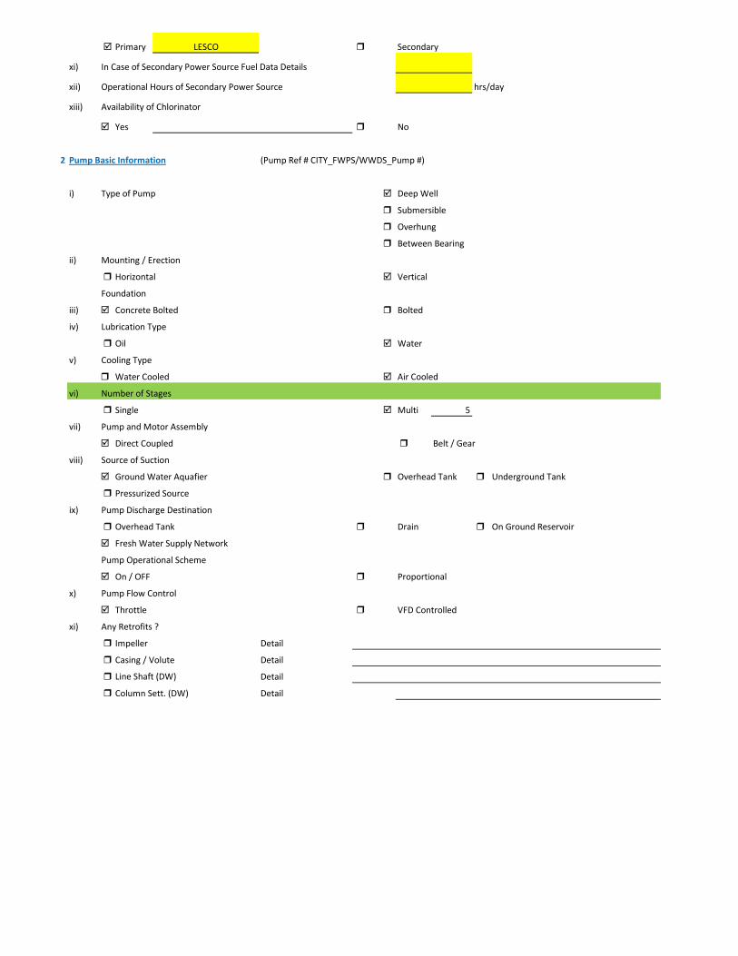
Primary LESCO Secondary
xi) In Case of Secondary Power Source Fuel Data Details
xii) Operational Hours of Secondary Power Source hrs/day
xiii) Availability of Chlorinator
Yes No
2 Pump Basic Information (Pump Ref # CITY_FWPS/WWDS_Pump #)
i) Type of Pump Deep Well
Submersible
Overhung
Between Bearing
ii) Mounting / Erection
Horizontal Vertical
Foundation
iii) Concrete Bolted Bolted
iv) Lubrication Type
Oil Water
v) Cooling Type
Water Cooled Air Cooled
vi) Number of Stages
Single Multi 5
vii) Pump and Motor Assembly
Direct Coupled Belt / Gear
viii) Source of Suction
Ground Water Aquafier Overhead Tank Underground Tank
Pressurized Source
ix) Pump Discharge Destination
Overhead Tank Drain On Ground Reservoir
Fresh Water Supply Network
Pump Operational Scheme
On / OFF Proportional
x) Pump Flow Control
Throttle VFD Controlled
xi) Any Retrofits ?
Impeller Detail
Casing / Volute Detail
Line Shaft (DW) Detail
Column Sett. (DW) Detail
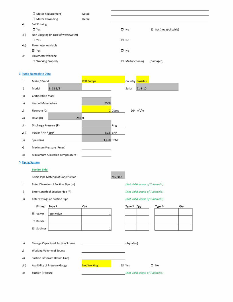
Motor Replacement Detail
Motor Rewinding Detail
xii) Self Priming
Yes No NA (not applicable)
xiii) Non Clogging (In case of wastewater)
Yes No
xiv) Flowmeter Available
Yes No
xv) Flowmeter Working
Working Properly Malfunctioning (Damaged)
3 Pump Nameplate Data
i) Make / Brand KSB Pumps Country Pakistan
ii) Model B. 12 B/5 Serial 21-8-10
iii) Certification Mark
iv) Year of Manufacture 2008
v) Flowrate (Q) 2 Cusec 204 m3/hr
vi) Head (H) 210 ft
vii) Discharge Pressure (P) Psig
viii) Power / HP / BHP 59.5 BHP
ix) Speed (n) 1,450 RPM
x) Maximum Pressure (Pmax)
xi) Maxiumum Allowable Temperature
5 Piping System
Suction Side
Select Pipe Material of Construction MS Pipe
i) Enter Diameter of Suction Pipe (In) (Not Valid incase of Tubewells)
ii) Enter Length of Suction Pipe (ft) (Not Valid incase of Tubewells)
iii) Enter Fittings on Suction Pipe (Not Valid incase of Tubewells)
Fitting Type 1 Qty Type 2 Qty Type 3 Qty
Valves Foot Valve 1
Bends
Strainer 1
iv) Storage Capacity of Suction Source (Aquafier)
v) Working Volume of Source
vi) Suction Lift (from Datum Line)
viii) Availbility of Pressure Gauge Not Working Yes No
ix) Suction Pressure (Not Valid incase of Tubewells)

Discharge Side
Pipe Material of Construction MS Pipe
i) Diameter of Discharge Pipe 8 inch
ii) Length of Discharge Pipe (Not known as directly connected to network underground)
iii) Fittings on Discharge Pipe
Fitting Type 1 Qty Type 2 Qty Type 3 Qty
Valves Control 1 Check 1
Bends Elbow 1
Strainer
iv) Storage Capacity of Discharge Destination (Not known as directly connected to network underground))
v) Working Volume of Discharge Destination (Not known as directly connected to network underground))
vi) Discharge Elevation (from Datum Line) (In case of no gauge)
vii) Availbility of Pressure Gauge Not Working Yes No (Installed by Team)
viii) Discharge Pressure 2 psig
6 Motor Nameplate Data
i) Manufacturer Siemens
ii) Rated kW / hp 80 hp 60 kW
iii) Voltage Range (Volts) 380 Volts
iv) Current (Ampere) 115
v) Power Factor (Cos ɸ) 0.85
Efficiency Class
IE3 Eff 1
IE2 Eff 2
IE1 Eff 3
Standard Efficiency
vi) Motor Speed 1,488 RPM
vii) Reference Frequency 50 C/S
viii) Insulation Class F
ix) Motor Frame Size 250 M
x)
7 Electrical System Observations
i) Electrical Meter Reference Number
ii) Meter Reading
iii) Meter Time and Date
Correct FALSE

Lag by Lead by
iv) Transformer Rating (kVA) 100 Condition OK
Pump O & M Cost
v) Motor Starting Method
Direct Online Star (Wye) - Delta
Autotransformer Starter Soft Starter
Variable Frequency Drives
v) Electrical Protections Available
Earthing / Grounding Fuses or Miniature Circuit Breaker (MCB)
Earth Leakage Circuit Breaker (ELCB) and Residual Current Circuit Breaker (RCCB)
PFI Plant 30kvar(operational)
Panel Condition/Issues Good
Gland Leakage moderate leakage
Non Return Valve ok
Chlorinator ok
Flow Meter Not working
Pressure Gauge Not working
Bore Hole in Front of PanYes
Wiring Good
Housekeeping Fair
Motor Terminal
Foundation/Civil work ok
Ratchet Plate Not Working
Field Measurements
8 Flow Measurement
i) Flow Measurement Location
Discharge Pipe Suction Pipe
ii) Pipe Material of Construction MS Pipe
iii) Paint on Pipe Yes No
iv) Pipe Diameter 8 inches (on which flowmeter is clamped)
v) Pipe Perimeter 720 mm (on which flowmeter is clamped)
vi) Type of Clamping (V/N/Z) V
viii) Flow Measurement 160 m3/hr (Through Transit Time Ultrasonic Flowmeter)
Velocity in Pipe 1.37 m/sec
Pressure
i) Pressure at Discharge Side of Pump 2 psig
ii) Pressure at Suction Side of Pump (Not Valid incase of Tubewells)

iii) Water Shutoff Head
Levels
i) Static Water Level 38 meter Estimated
ii) Pumping Water Level 43 meter (estimated due to gland leakage and catching of wire by suction)
Electric Measurements
i) Voltage 385 386.9 388.5
ii) Ampere 76.8 75.2 71.9
iii) Power Factor 0.76
iv) Appearant Power (kVA) 49.9
v) Running Power (kW) 38
vi) Reactive Power (kVAr) 32.5
vi) Motor Working on Loading Basis 63.3 %
Oversize Undersize Properly Sized
Speed
i) Speed of Motor 1,488 RPM
ii) Speed of Pump Impeller 1,450 RPM
Noise Level
Noise Level (db(A)) Avg. Max: 95.2
Thermal Imaging
i) Motor Motor Pump Coupling
Pump Volute Casing Pump Bearings
Electric Panels
Calculations
10
i) Drawdown of Pump (Pumping water level - Static Water Level) 16.4 ft
ii) Static Suction Head (Only for WW Pump) ft
iii) Suction Side Frictional Head (Only for WW Pump) ft
iv) Dynamic Suction Head (ii+iii) (Only for WW Pump) ft
v) Discharge Head (Pressure Gauge) 4.62 ft
vi) Discharge Side Frictional Head 4.91 ft
vii) Dynamic Discharge Head (v+vi) 9.53 ft
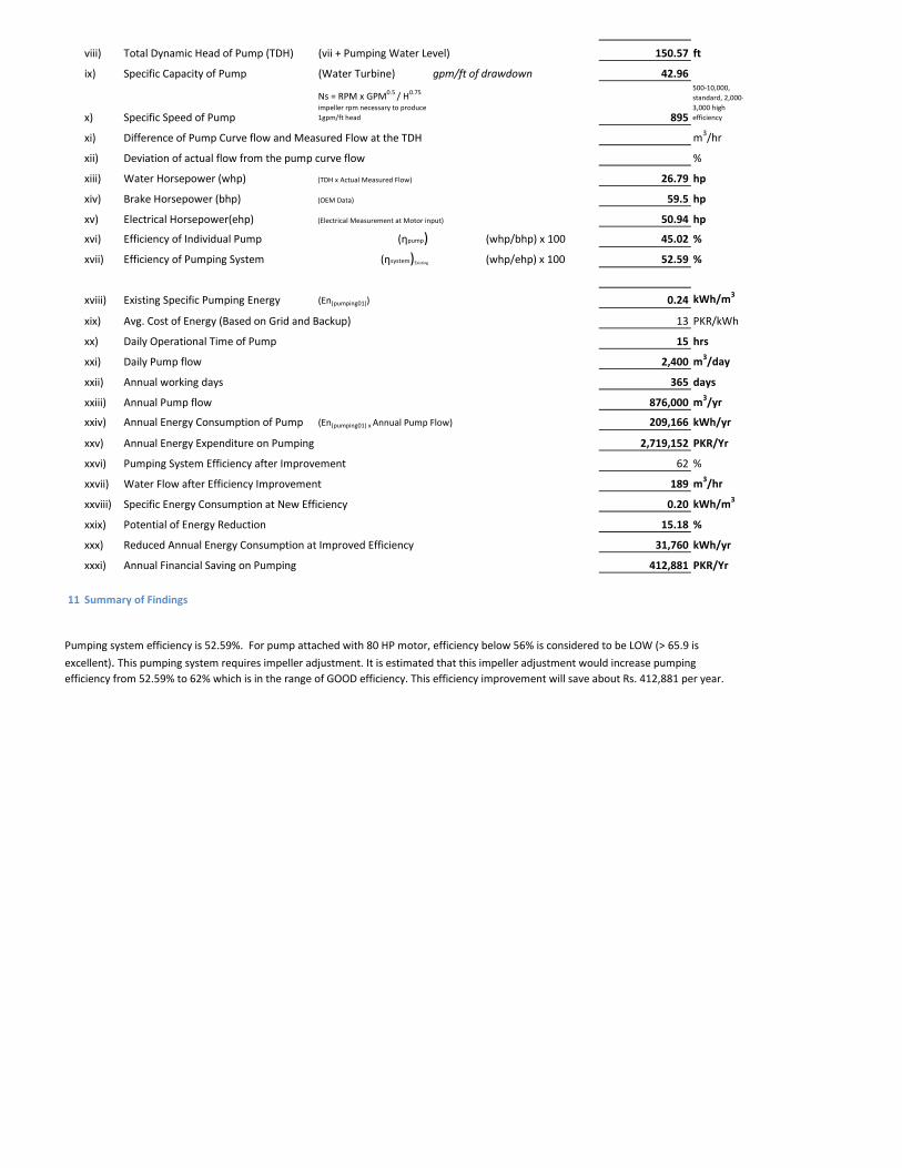
viii) Total Dynamic Head of Pump (TDH) (vii + Pumping Water Level) 150.57 ft
ix) Specific Capacity of Pump (Water Turbine) gpm/ft of drawdown 42.96
x) Specific Speed of Pump
Ns = RPM x GPM0.5 / H0.75
impeller rpm necessary to produce 1gpm/ft head 895
500-10,000, standard, 2,000-3,000 high efficiency
xi) Difference of Pump Curve flow and Measured Flow at the TDH m3/hr
xii) Deviation of actual flow from the pump curve flow %
xiii) Water Horsepower (whp) (TDH x Actual Measured Flow) 26.79 hp
xiv) Brake Horsepower (bhp) (OEM Data) 59.5 hp
xv) Electrical Horsepower(ehp) (Electrical Measurement at Motor input) 50.94 hp
xvi) Efficiency of Individual Pump (ηpump) (whp/bhp) x 100 45.02 %
xvii) Efficiency of Pumping System (ηsystem)Existing (whp/ehp) x 100 52.59 %
xviii) Existing Specific Pumping Energy (En(pumping01)) 0.24 kWh/m3
xix) Avg. Cost of Energy (Based on Grid and Backup) 13 PKR/kWh
xx) Daily Operational Time of Pump 15 hrs
xxi) Daily Pump flow 2,400 m3/day
xxii) Annual working days 365 days
xxiii) Annual Pump flow 876,000 m3/yr
xxiv) Annual Energy Consumption of Pump (En(pumping01) x Annual Pump Flow) 209,166 kWh/yr
xxv) Annual Energy Expenditure on Pumping 2,719,152 PKR/Yr
xxvi) Pumping System Efficiency after Improvement 62 %
xxvii) Water Flow after Efficiency Improvement 189 m3/hr
xxviii) Specific Energy Consumption at New Efficiency 0.20 kWh/m3
xxix) Potential of Energy Reduction 15.18 %
xxx) Reduced Annual Energy Consumption at Improved Efficiency 31,760 kWh/yr
xxxi) Annual Financial Saving on Pumping 412,881 PKR/Yr
11 Summary of Findings
Pumping system efficiency is 52.59%. For pump attached with 80 HP motor, efficiency below 56% is considered to be LOW (> 65.9 is
excellent). This pumping system requires impeller adjustment. It is estimated that this impeller adjustment would increase pumping efficiency from 52.59% to 62% which is in the range of GOOD efficiency. This efficiency improvement will save about Rs. 412,881 per year.
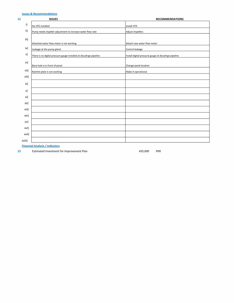
Issues & Recommendations
12 ISSUES RECOMMENDATIONS
i)
ii)
iii)
iv)
v)
vi)
vii)
viii)
ix)
x)
xi)
xii)
xiii)
xiv)
xv)
xvi)
xvii)
xviii)
Financial Analysis / Indicators
12 Estimated Investment for Improvement Plan 435,000 PKR
Install digital pressure gauge at discahrge pipelineThere is no digital pressure gauge installed at discahrge pipeline
Control leakageLeakage at the pump gland
Pump needs impeller adjustment to increase water flow rate Adjust impellers
Attached water flow meter is not working Attach new water flow meter
No VFD installed Install VFD
Change panel locationBore hole is in front of panel
Ratchet plate is not working Make it operational

1 Pumping Station Information
1 Fresh Water Supply
2 Wastewater Disposal
3 Waste Water Treatment Plant
4 Water Treatment Plant
Name of Engineer
WASA Staff Name
i) Name of Pumping Station Para Shoot Colony
ii) Name of Subdivision Mughalpura , Lahore
iii) Operator Name & Contact Abdul Saeed
iv) Total Number of Pumps Installed 1
v) Total Number of Pumps in Operation 1
vi) Year of Starting Operation
vii) Types of Pumps
Standard Deep Well Water Turbine Pumps Qty 1
Submersible Deep Well Water Turbine Pumps Qty
Centrifugal Pump Qty
vi) Operational Scheme of Pumps Qty
Independent 1
Series
Parallel
vii) Any Header / Tank / Reservoir
Yes No
viii) Any Record Keeping
Time Flow Pressure
Level Quality of Water Power Consumption
Maintenance Record Electricity Bill Fuel Consumption Data
viii) Daily Operational Time 15 hrs/day
ix) Annual Working Days 365 days
x) Source of Power
Energy Report of WASA Pumps

Primary LESCO Secondary
xi) In Case of Secondary Power Source Fuel Data Details
xii) Operational Hours of Secondary Power Source hrs/day
xiii) Availability of Chlorinator
Yes No
2 Pump Basic Information (Pump Ref # CITY_FWPS/WWDS_Pump #)
i) Type of Pump Deep Well
Submersible
Overhung
Between Bearing
ii) Mounting / Erection
Horizontal Vertical
Foundation
iii) Concrete Bolted Bolted
iv) Lubrication Type
Oil Water
v) Cooling Type
Water Cooled Air Cooled
vi) Number of Stages
Single Multi 5
vii) Pump and Motor Assembly
Direct Coupled Belt / Gear
viii) Source of Suction
Ground Water Aquafier Overhead Tank Underground Tank
Pressurized Source
ix) Pump Discharge Destination
Overhead Tank Drain On Ground Reservoir
Fresh Water Supply Network
Pump Operational Scheme
On / OFF Proportional
x) Pump Flow Control
Throttle VFD Controlled
xi) Any Retrofits ?
Impeller Detail
Casing / Volute Detail
Line Shaft (DW) Detail
Column Sett. (DW) Detail

Motor Replacement Detail
Motor Rewinding Detail
xii) Self Priming
Yes No NA (not applicable)
xiii) Non Clogging (In case of wastewater)
Yes No
xiv) Flowmeter Available
Yes No
xv) Flowmeter Working
Working Properly Malfunctioning (Damaged)
3 Pump Nameplate Data
i) Make / Brand KSB Pumps Country Pakistan
ii) Model B. 12 B/5 Serial 9972109511/300/3
iii) Certification Mark
iv) Year of Manufacture 2012
v) Flowrate (Q) 2 Cusec 204 m3/hr
vi) Head (H) 210 ft
vii) Discharge Pressure (P) Psig
viii) Power / HP / BHP 59.72 BHP
ix) Speed (n) 1,450 RPM
x) Maximum Pressure (Pmax)
xi) Maxiumum Allowable Temperature
5 Piping System
Suction Side
Select Pipe Material of Construction MS Pipe
i) Enter Diameter of Suction Pipe (In) (Not Valid incase of Tubewells)
ii) Enter Length of Suction Pipe (ft) (Not Valid incase of Tubewells)
iii) Enter Fittings on Suction Pipe (Not Valid incase of Tubewells)
Fitting Type 1 Qty Type 2 Qty Type 3 Qty
Valves Foot Valve 1
Bends
Strainer 1
iv) Storage Capacity of Suction Source (Aquafier)
v) Working Volume of Source
vi) Suction Lift (from Datum Line)
viii) Availbility of Pressure Gauge Yes No
ix) Suction Pressure (Not Valid incase of Tubewells)

Discharge Side
Pipe Material of Construction MS Pipe
i) Diameter of Discharge Pipe 8 inch
ii) Length of Discharge Pipe (Not known as directly connected to network underground)
iii) Fittings on Discharge Pipe
Fitting Type 1 Qty Type 2 Qty Type 3 Qty
Valves Control 1 Check 1
Bends Elbow 1
Strainer
iv) Storage Capacity of Discharge Destination (Not known as directly connected to network underground))
v) Working Volume of Discharge Destination (Not known as directly connected to network underground))
vi) Discharge Elevation (from Datum Line) (In case of no gauge)
vii) Availbility of Pressure Gauge Yes No
viii) Discharge Pressure 12 psig
6 Motor Nameplate Data
i) Manufacturer Siemens
ii) Rated kW / hp 80 hp 60 kW
iii) Voltage Range (Volts) 380 Volts
iv) Current (Ampere) 115
v) Power Factor (Cos ɸ) 0.85
Efficiency Class
IE3 Eff 1
IE2 Eff 2
IE1 Eff 3
Standard Efficiency
vi) Motor Speed 1,488 RPM
vii) Reference Frequency 50 C/S
viii) Insulation Class F
ix) Motor Frame Size 250 M
x)
7 Electrical System Observations
i) Electrical Meter Reference Number
ii) Meter Reading
iii) Meter Time and Date
Correct FALSE

Lag by Lead by
iv) Transformer Rating (kVA) 100 Condition OK
Pump O & M Cost
v) Motor Starting Method
Direct Online Star (Wye) - Delta
Autotransformer Starter Soft Starter
Variable Frequency Drives
v) Electrical Protections Available
Earthing / Grounding Fuses or Miniature Circuit Breaker (MCB)
Earth Leakage Circuit Breaker (ELCB) and Residual Current Circuit Breaker (RCCB)
PFI Plant 10kvar(Operational)
Panel Condition/Issues Excellent
Gland Leakage Minor leakage
Non Return Valve ok
Chlorinator Not Available
Flow Meter Not Available
Pressure Gauge ok
Bore Hole in Front of PanYes
Wiring Good
Housekeeping Fair
Motor Terminal
Foundation/Civil work ok
Ratchet Plate ok
Field Measurements
8 Flow Measurement
i) Flow Measurement Location
Discharge Pipe Suction Pipe
ii) Pipe Material of Construction MS Pipe
iii) Paint on Pipe Yes No
iv) Pipe Diameter 8 inches (on which flowmeter is clamped)
v) Pipe Perimeter 720 mm (on which flowmeter is clamped)
vi) Type of Clamping (V/N/Z) V
viii) Flow Measurement 243 m3/hr (Through Transit Time Ultrasonic Flowmeter)
Velocity in Pipe 2.08 m/sec
Pressure
i) Pressure at Discharge Side of Pump 15 psig
ii) Pressure at Suction Side of Pump (Not Valid incase of Tubewells)

iii) Water Shutoff Head
Levels
i) Static Water Level 38 meter Estimated
ii) Pumping Water Level 43 meter (estimated due to gland leakage and catching of wire by suction)
Electric Measurements
i) Voltage 396.9 396 394
ii) Ampere 108.2 103.2 106.9
iii) Power Factor 0.86
iv) Appearant Power (kVA) 72.6
v) Running Power (kW) 62.5
vi) Reactive Power (kVAr) 37.1
vi) Motor Working on Loading Basis 104.1 %
Oversize Undersize Properly Sized
Speed
i) Speed of Motor 1,488 RPM
ii) Speed of Pump Impeller 1,450 RPM
Noise Level
Noise Level (db(A)) Avg. Max: 90.3
Thermal Imaging
i) Motor Motor Pump Coupling
Pump Volute Casing Pump Bearings
Electric Panels
Calculations
10
i) Drawdown of Pump (Pumping water level - Static Water Level) 16.4 ft
ii) Static Suction Head (Only for WW Pump) ft
iii) Suction Side Frictional Head (Only for WW Pump) ft
iv) Dynamic Suction Head (ii+iii) (Only for WW Pump) ft
v) Discharge Head (Pressure Gauge) 34.65 ft
vi) Discharge Side Frictional Head 11.18 ft
vii) Dynamic Discharge Head (v+vi) 45.83 ft
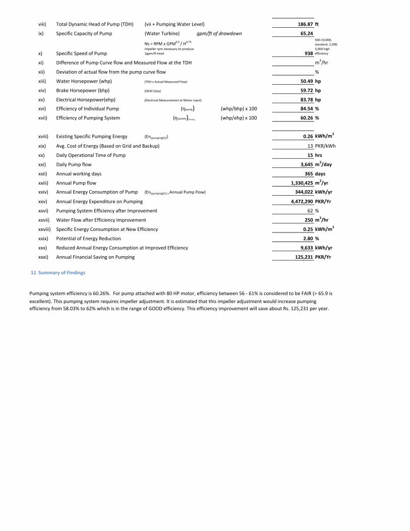
viii) Total Dynamic Head of Pump (TDH) (vii + Pumping Water Level) 186.87 ft
ix) Specific Capacity of Pump (Water Turbine) gpm/ft of drawdown 65.24
x) Specific Speed of Pump
Ns = RPM x GPM0.5 / H0.75
impeller rpm necessary to produce 1gpm/ft head 938
500-10,000, standard, 2,000-3,000 high efficiency
xi) Difference of Pump Curve flow and Measured Flow at the TDH m3/hr
xii) Deviation of actual flow from the pump curve flow %
xiii) Water Horsepower (whp) (TDH x Actual Measured Flow) 50.49 hp
xiv) Brake Horsepower (bhp) (OEM Data) 59.72 hp
xv) Electrical Horsepower(ehp) (Electrical Measurement at Motor input) 83.78 hp
xvi) Efficiency of Individual Pump (ηpump) (whp/bhp) x 100 84.54 %
xvii) Efficiency of Pumping System (ηsystem)Existing (whp/ehp) x 100 60.26 %
xviii) Existing Specific Pumping Energy (En(pumping01)) 0.26 kWh/m3
xix) Avg. Cost of Energy (Based on Grid and Backup) 13 PKR/kWh
xx) Daily Operational Time of Pump 15 hrs
xxi) Daily Pump flow 3,645 m3/day
xxii) Annual working days 365 days
xxiii) Annual Pump flow 1,330,425 m3/yr
xxiv) Annual Energy Consumption of Pump (En(pumping01) x Annual Pump Flow) 344,022 kWh/yr
xxv) Annual Energy Expenditure on Pumping 4,472,290 PKR/Yr
xxvi) Pumping System Efficiency after Improvement 62 %
xxvii) Water Flow after Efficiency Improvement 250 m3/hr
xxviii) Specific Energy Consumption at New Efficiency 0.25 kWh/m3
xxix) Potential of Energy Reduction 2.80 %
xxx) Reduced Annual Energy Consumption at Improved Efficiency 9,633 kWh/yr
xxxi) Annual Financial Saving on Pumping 125,231 PKR/Yr
11 Summary of Findings
Pumping system efficiency is 60.26%. For pump attached with 80 HP motor, efficiency between 56 - 61% is considered to be FAIR (> 65.9 is
excellent). This pumping system requires impeller adjustment. It is estimated that this impeller adjustment would increase pumping efficiency from 58.03% to 62% which is in the range of GOOD efficiency. This efficiency improvement will save about Rs. 125,231 per year.
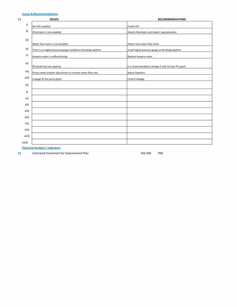
Issues & Recommendations
12 ISSUES RECOMMENDATIONS
i)
ii)
iii)
iv)
v)
vi)
vii)
viii)
ix)
x)
xi)
xii)
xiii)
xiv)
xv)
xvi)
xvii)
xviii)
Financial Analysis / Indicators
12 Estimated Investment for Improvement Plan 503,500 PKR
Replace Ampere meterAmpere meter is malfunctioning
Install digital pressure gauge at discahrge pipelineThere is no digital pressure gauge installed at discahrge pipeline
Chlorinator is not avaialble Attach chlorinator and make it operationalize
Water flow meter is not Avaiable Attach new water flow meter
No VFD installed Install VFD
Control leakageLeakage at the pump gland
It is recommended to change it with 25 kvar PFI panelPFI panel has Low capacity
Pump needs impeller adjustment to increase water flow rate Adjust impellers
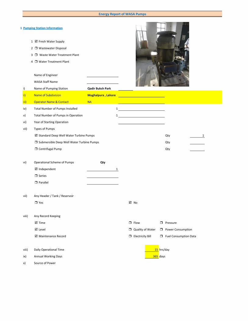
1 Pumping Station Information
1 Fresh Water Supply
2 Wastewater Disposal
3 Waste Water Treatment Plant
4 Water Treatment Plant
Name of Engineer
WASA Staff Name
i) Name of Pumping Station Qadir Buksh Park
ii) Name of Subdivision Mughalpura , Lahore
iii) Operator Name & Contact NA
iv) Total Number of Pumps Installed 1
v) Total Number of Pumps in Operation 1
vi) Year of Starting Operation
vii) Types of Pumps
Standard Deep Well Water Turbine Pumps Qty 1
Submersible Deep Well Water Turbine Pumps Qty
Centrifugal Pump Qty
vi) Operational Scheme of Pumps Qty
Independent 1
Series
Parallel
vii) Any Header / Tank / Reservoir
Yes No
viii) Any Record Keeping
Time Flow Pressure
Level Quality of Water Power Consumption
Maintenance Record Electricity Bill Fuel Consumption Data
viii) Daily Operational Time 15 hrs/day
ix) Annual Working Days 365 days
x) Source of Power
Energy Report of WASA Pumps

Primary LESCO Secondary
xi) In Case of Secondary Power Source Fuel Data Details
xii) Operational Hours of Secondary Power Source hrs/day
xiii) Availability of Chlorinator
Yes No
2 Pump Basic Information (Pump Ref # CITY_FWPS/WWDS_Pump #)
i) Type of Pump Deep Well
Submersible
Overhung
Between Bearing
ii) Mounting / Erection
Horizontal Vertical
Foundation
iii) Concrete Bolted Bolted
iv) Lubrication Type
Oil Water
v) Cooling Type
Water Cooled Air Cooled
vi) Number of Stages
Single Multi 5
vii) Pump and Motor Assembly
Direct Coupled Belt / Gear
viii) Source of Suction
Ground Water Aquafier Overhead Tank Underground Tank
Pressurized Source
ix) Pump Discharge Destination
Overhead Tank Drain On Ground Reservoir
Fresh Water Supply Network
Pump Operational Scheme
On / OFF Proportional
x) Pump Flow Control
Throttle VFD Controlled
xi) Any Retrofits ?
Impeller Detail
Casing / Volute Detail
Line Shaft (DW) Detail
Column Sett. (DW) Detail

Motor Replacement Detail
Motor Rewinding Detail
xii) Self Priming
Yes No NA (not applicable)
xiii) Non Clogging (In case of wastewater)
Yes No
xiv) Flowmeter Available
Yes No
xv) Flowmeter Working
Working Properly Malfunctioning (Damaged)
3 Pump Nameplate Data
i) Make / Brand KSB Pumps Country Pakistan
ii) Model B. 12 B/5 Serial
iii) Certification Mark
iv) Year of Manufacture 2012
v) Flowrate (Q) 2 Cusec 204 m3/hr
vi) Head (H) 210 ft
vii) Discharge Pressure (P) Psig
viii) Power / HP / BHP 59.72 BHP
ix) Speed (n) 1,450 RPM
x) Maximum Pressure (Pmax)
xi) Maxiumum Allowable Temperature
5 Piping System
Suction Side
Select Pipe Material of Construction MS Pipe
i) Enter Diameter of Suction Pipe (In) (Not Valid incase of Tubewells)
ii) Enter Length of Suction Pipe (ft) (Not Valid incase of Tubewells)
iii) Enter Fittings on Suction Pipe (Not Valid incase of Tubewells)
Fitting Type 1 Qty Type 2 Qty Type 3 Qty
Valves Foot Valve 1
Bends
Strainer 1
iv) Storage Capacity of Suction Source (Aquafier)
v) Working Volume of Source
vi) Suction Lift (from Datum Line)
viii) Availbility of Pressure Gauge Yes No
ix) Suction Pressure (Not Valid incase of Tubewells)

Discharge Side
Pipe Material of Construction MS Pipe
i) Diameter of Discharge Pipe 8 inch
ii) Length of Discharge Pipe (Not known as directly connected to network underground)
iii) Fittings on Discharge Pipe
Fitting Type 1 Qty Type 2 Qty Type 3 Qty
Valves Control 1 Check 1
Bends Elbow 1
Strainer
iv) Storage Capacity of Discharge Destination (Not known as directly connected to network underground))
v) Working Volume of Discharge Destination (Not known as directly connected to network underground))
vi) Discharge Elevation (from Datum Line) (In case of no gauge)
vii) Availbility of Pressure Gauge Yes No (Installed by Team)
viii) Discharge Pressure 5 psig
6 Motor Nameplate Data
i) Manufacturer Siemens
ii) Rated kW / hp 80 hp 60 kW
iii) Voltage Range (Volts) 380 Volts
iv) Current (Ampere) 115
v) Power Factor (Cos ɸ) 0.85
Efficiency Class
IE3 Eff 1
IE2 Eff 2
IE1 Eff 3
Standard Efficiency
vi) Motor Speed 1,488 RPM
vii) Reference Frequency 50 C/S
viii) Insulation Class F
ix) Motor Frame Size 250 M
x)
7 Electrical System Observations
i) Electrical Meter Reference Number
ii) Meter Reading
iii) Meter Time and Date
Correct FALSE

Lag by Lead by
iv) Transformer Rating (kVA) 100 Condition OK
Pump O & M Cost
v) Motor Starting Method
Direct Online Star (Wye) - Delta
Autotransformer Starter Soft Starter
Variable Frequency Drives
v) Electrical Protections Available
Earthing / Grounding Fuses or Miniature Circuit Breaker (MCB)
Earth Leakage Circuit Breaker (ELCB) and Residual Current Circuit Breaker (RCCB)
PFI Plant 25kvar (operational)
Panel Condition/Issues Excellent
Gland Leakage No leakage
Non Return Valve ok
Chlorinator Not Available
Flow Meter Not Available
Pressure Gauge yes
Bore Hole in Front of Panno
Wiring Good
Housekeeping Fair
Motor Terminal Ok
Foundation/Civil work ok
Ratchet Plate ok
Field Measurements
8 Flow Measurement
i) Flow Measurement Location
Discharge Pipe Suction Pipe
ii) Pipe Material of Construction MS Pipe
iii) Paint on Pipe Yes No
iv) Pipe Diameter 8 inches (on which flowmeter is clamped)
v) Pipe Perimeter mm (on which flowmeter is clamped)
vi) Type of Clamping (V/N/Z) V
viii) Flow Measurement 260 m3/hr (Through Transit Time Ultrasonic Flowmeter)
Velocity in Pipe 2.23 m/sec
Pressure
i) Pressure at Discharge Side of Pump 5 psig
ii) Pressure at Suction Side of Pump (Not Valid incase of Tubewells)

iii) Water Shutoff Head
Levels
i) Static Water Level 38 meter Estimated
ii) Pumping Water Level 43 meter (estimated due to gland leakage and catching of wire by suction)
Electric Measurements
i) Voltage 359.5 357.5 357.9
ii) Ampere 77.8 80 82
iii) Power Factor 0.94
iv) Appearant Power (kVA) 49.5
v) Running Power (kW) 46.6
vi) Reactive Power (kVAr) 16.9
vi) Motor Working on Loading Basis 77.6 %
Oversize Undersize Properly Sized
Speed
i) Speed of Motor 1,488 RPM
ii) Speed of Pump Impeller 1,450 RPM
Noise Level
Noise Level (db(A)) Avg. Max: 93.1
Thermal Imaging
i) Motor Motor Pump Coupling
Pump Volute Casing Pump Bearings
Electric Panels
Calculations
10
i) Drawdown of Pump (Pumping water level - Static Water Level) 16.4 ft
ii) Static Suction Head (Only for WW Pump) ft
iii) Suction Side Frictional Head (Only for WW Pump) ft
iv) Dynamic Suction Head (ii+iii) (Only for WW Pump) ft
v) Discharge Head (Pressure Gauge) 11.55 ft
vi) Discharge Side Frictional Head 12.77 ft
vii) Dynamic Discharge Head (v+vi) 24.32 ft
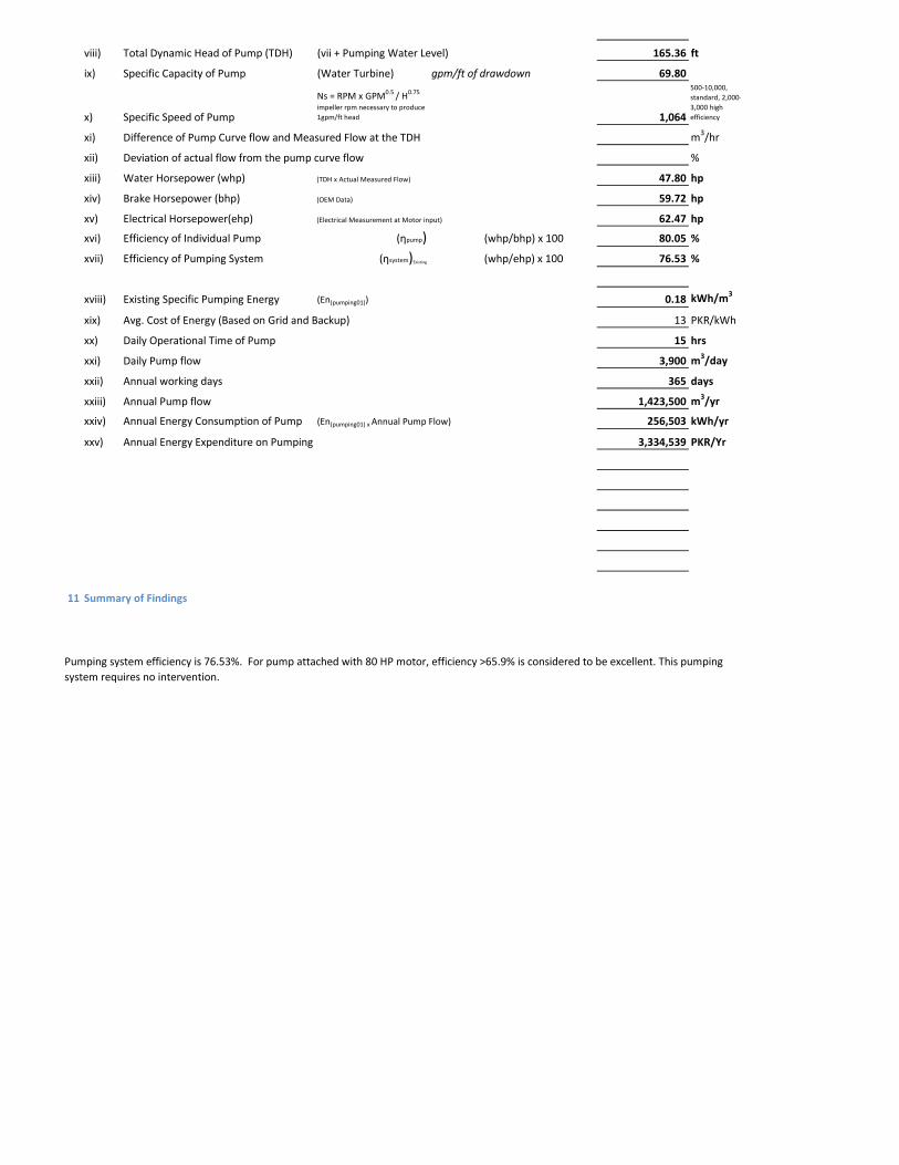
viii) Total Dynamic Head of Pump (TDH) (vii + Pumping Water Level) 165.36 ft
ix) Specific Capacity of Pump (Water Turbine) gpm/ft of drawdown 69.80
x) Specific Speed of Pump
Ns = RPM x GPM0.5 / H0.75
impeller rpm necessary to produce 1gpm/ft head 1,064
500-10,000, standard, 2,000-3,000 high efficiency
xi) Difference of Pump Curve flow and Measured Flow at the TDH m3/hr
xii) Deviation of actual flow from the pump curve flow %
xiii) Water Horsepower (whp) (TDH x Actual Measured Flow) 47.80 hp
xiv) Brake Horsepower (bhp) (OEM Data) 59.72 hp
xv) Electrical Horsepower(ehp) (Electrical Measurement at Motor input) 62.47 hp
xvi) Efficiency of Individual Pump (ηpump) (whp/bhp) x 100 80.05 %
xvii) Efficiency of Pumping System (ηsystem)Existing (whp/ehp) x 100 76.53 %
xviii) Existing Specific Pumping Energy (En(pumping01)) 0.18 kWh/m3
xix) Avg. Cost of Energy (Based on Grid and Backup) 13 PKR/kWh
xx) Daily Operational Time of Pump 15 hrs
xxi) Daily Pump flow 3,900 m3/day
xxii) Annual working days 365 days
xxiii) Annual Pump flow 1,423,500 m3/yr
xxiv) Annual Energy Consumption of Pump (En(pumping01) x Annual Pump Flow) 256,503 kWh/yr
xxv) Annual Energy Expenditure on Pumping 3,334,539 PKR/Yr
11 Summary of Findings
Pumping system efficiency is 76.53%. For pump attached with 80 HP motor, efficiency >65.9% is considered to be excellent. This pumping system requires no intervention.
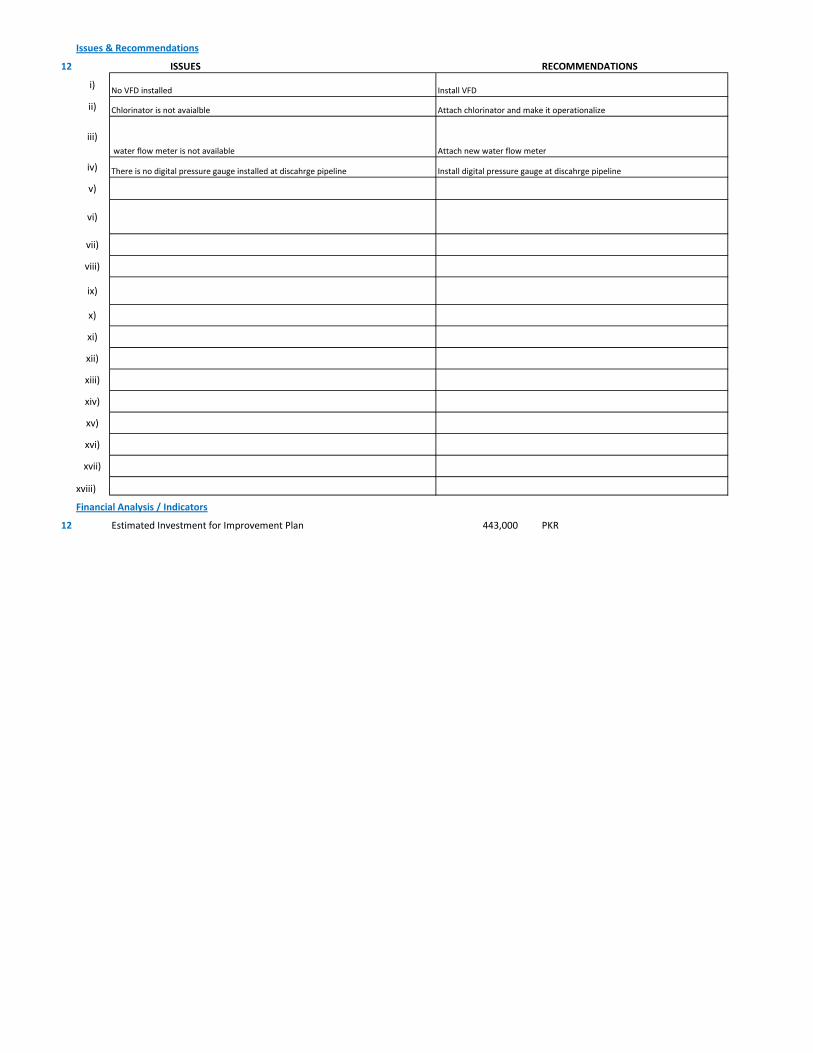
Issues & Recommendations
12 ISSUES RECOMMENDATIONS
i)
ii)
iii)
iv)
v)
vi)
vii)
viii)
ix)
x)
xi)
xii)
xiii)
xiv)
xv)
xvi)
xvii)
xviii)
Financial Analysis / Indicators
12 Estimated Investment for Improvement Plan 443,000 PKR
Install digital pressure gauge at discahrge pipelineThere is no digital pressure gauge installed at discahrge pipeline
Chlorinator is not avaialble Attach chlorinator and make it operationalize
water flow meter is not available Attach new water flow meter
No VFD installed Install VFD
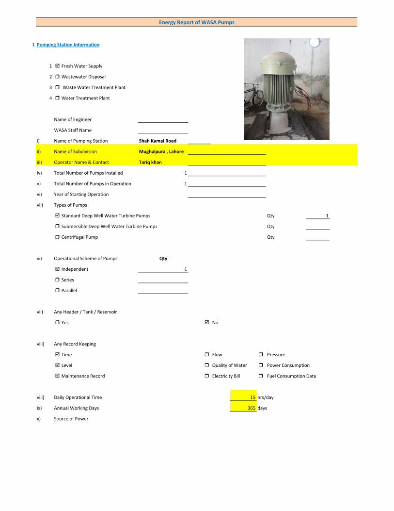
1 Pumping Station Information
1 Fresh Water Supply
2 Wastewater Disposal
3 Waste Water Treatment Plant
4 Water Treatment Plant
Name of Engineer
WASA Staff Name
i) Name of Pumping Station Shah Kamal Road
ii) Name of Subdivision Mughalpura , Lahore
iii) Operator Name & Contact Tariq khan
iv) Total Number of Pumps Installed 1
v) Total Number of Pumps in Operation 1
vi) Year of Starting Operation
vii) Types of Pumps
Standard Deep Well Water Turbine Pumps Qty 1
Submersible Deep Well Water Turbine Pumps Qty
Centrifugal Pump Qty
vi) Operational Scheme of Pumps Qty
Independent 1
Series
Parallel
vii) Any Header / Tank / Reservoir
Yes No
viii) Any Record Keeping
Time Flow Pressure
Level Quality of Water Power Consumption
Maintenance Record Electricity Bill Fuel Consumption Data
viii) Daily Operational Time 15 hrs/day
ix) Annual Working Days 365 days
x) Source of Power
Energy Report of WASA Pumps
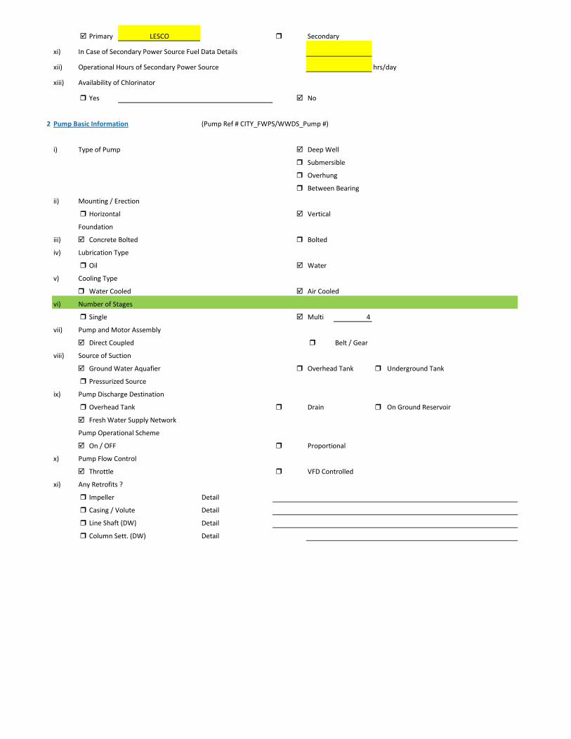
Primary LESCO Secondary
xi) In Case of Secondary Power Source Fuel Data Details
xii) Operational Hours of Secondary Power Source hrs/day
xiii) Availability of Chlorinator
Yes No
2 Pump Basic Information (Pump Ref # CITY_FWPS/WWDS_Pump #)
i) Type of Pump Deep Well
Submersible
Overhung
Between Bearing
ii) Mounting / Erection
Horizontal Vertical
Foundation
iii) Concrete Bolted Bolted
iv) Lubrication Type
Oil Water
v) Cooling Type
Water Cooled Air Cooled
vi) Number of Stages
Single Multi 4
vii) Pump and Motor Assembly
Direct Coupled Belt / Gear
viii) Source of Suction
Ground Water Aquafier Overhead Tank Underground Tank
Pressurized Source
ix) Pump Discharge Destination
Overhead Tank Drain On Ground Reservoir
Fresh Water Supply Network
Pump Operational Scheme
On / OFF Proportional
x) Pump Flow Control
Throttle VFD Controlled
xi) Any Retrofits ?
Impeller Detail
Casing / Volute Detail
Line Shaft (DW) Detail
Column Sett. (DW) Detail

Motor Replacement Detail
Motor Rewinding Detail
xii) Self Priming
Yes No NA (not applicable)
xiii) Non Clogging (In case of wastewater)
Yes No
xiv) Flowmeter Available
Yes No
xv) Flowmeter Working
Working Properly Malfunctioning (Damaged)
3 Pump Nameplate Data
i) Make / Brand Country
ii) Model Serial
iii) Certification Mark
iv) Year of Manufacture 1996
v) Flowrate (Q) 4 Cusec 408 m3/hr
vi) Head (H) 210 ft
vii) Discharge Pressure (P) Psig
viii) Power / HP / BHP 118.59 BHP
ix) Speed (n) RPM
x) Maximum Pressure (Pmax)
xi) Maxiumum Allowable Temperature
5 Piping System
Suction Side
Select Pipe Material of Construction MS Pipe
i) Enter Diameter of Suction Pipe (In) (Not Valid incase of Tubewells)
ii) Enter Length of Suction Pipe (ft) (Not Valid incase of Tubewells)
iii) Enter Fittings on Suction Pipe (Not Valid incase of Tubewells)
Fitting Type 1 Qty Type 2 Qty Type 3 Qty
Valves Foot Valve 1
Bends
Strainer 1
iv) Storage Capacity of Suction Source (Aquafier)
v) Working Volume of Source
vi) Suction Lift (from Datum Line)
viii) Availbility of Pressure Gauge Yes No
ix) Suction Pressure (Not Valid incase of Tubewells)

Discharge Side
Pipe Material of Construction MS Pipe
i) Diameter of Discharge Pipe 10 inch
ii) Length of Discharge Pipe (Not known as directly connected to network underground)
iii) Fittings on Discharge Pipe
Fitting Type 1 Qty Type 2 Qty Type 3 Qty
Valves Control 1 Check 1
Bends Elbow 1
Strainer
iv) Storage Capacity of Discharge Destination (Not known as directly connected to network underground))
v) Working Volume of Discharge Destination (Not known as directly connected to network underground))
vi) Discharge Elevation (from Datum Line) (In case of no gauge)
vii) Availbility of Pressure Gauge Yes No (Installed by Team)
viii) Discharge Pressure 6 psig
6 Motor Nameplate Data
i) Manufacturer Siemens
ii) Rated kW / hp 150 hp 112.5 kW
iii) Voltage Range (Volts) 380 Volts
iv) Current (Ampere) 214
v) Power Factor (Cos ɸ) 0.85
Efficiency Class
IE3 Eff 1
IE2 Eff 2
IE1 Eff 3
Standard Efficiency
vi) Motor Speed 1,488 RPM
vii) Reference Frequency 50 C/S
viii) Insulation Class F
ix) Motor Frame Size 315 S
x)
7 Electrical System Observations
i) Electrical Meter Reference Number
ii) Meter Reading
iii) Meter Time and Date
Correct FALSE

Lag by Lead by
iv) Transformer Rating (kVA) 200 Condition OK
Pump O & M Cost
v) Motor Starting Method
Direct Online Star (Wye) - Delta
Autotransformer Starter Soft Starter
Variable Frequency Drives
v) Electrical Protections Available
Earthing / Grounding Fuses or Miniature Circuit Breaker (MCB)
Earth Leakage Circuit Breaker (ELCB) and Residual Current Circuit Breaker (RCCB)
PFI Plant Not installed
Panel Condition/Issues poor
Gland Leakage moderate leakage
Non Return Valve ok
Chlorinator Not Available
Flow Meter Not Available
Pressure Gauge Not Available
Bore Hole in Front of PanYes
Wiring poor
Housekeeping Fair
Motor Terminal
Foundation/Civil work ok
Ratchet Plate Not Working
Field Measurements
8 Flow Measurement
i) Flow Measurement Location
Discharge Pipe Suction Pipe
ii) Pipe Material of Construction MS Pipe
iii) Paint on Pipe Yes No
iv) Pipe Diameter 10 inches (on which flowmeter is clamped)
v) Pipe Perimeter mm (on which flowmeter is clamped)
vi) Type of Clamping (V/N/Z) V
viii) Flow Measurement 150 m3/hr (Through Transit Time Ultrasonic Flowmeter)
Velocity in Pipe 0.82 m/sec
Pressure
i) Pressure at Discharge Side of Pump 6 psig
ii) Pressure at Suction Side of Pump (Not Valid incase of Tubewells)

iii) Water Shutoff Head
Levels
i) Static Water Level 38 meter Estimated
ii) Pumping Water Level 43 meter (estimated due to gland leakage and catching of wire by suction)
Electric Measurements
i) Voltage 382 378.8 383.2
ii) Ampere 152 155.6 149.5
iii) Power Factor 0.75
iv) Appearant Power (kVA) 100.5
v) Running Power (kW) 75.4
vi) Reactive Power (kVAr) 66.5
vi) Motor Working on Loading Basis 68.5 %
Oversize Undersize Properly Sized
Speed
i) Speed of Motor 1,488 RPM
ii) Speed of Pump Impeller RPM
Noise Level
Noise Level (db(A)) Avg. Max: 93.8
Thermal Imaging
i) Motor Motor Pump Coupling
Pump Volute Casing Pump Bearings
Electric Panels
Calculations
10
i) Drawdown of Pump (Pumping water level - Static Water Level) 16.4 ft
ii) Static Suction Head (Only for WW Pump) ft
iii) Suction Side Frictional Head (Only for WW Pump) ft
iv) Dynamic Suction Head (ii+iii) (Only for WW Pump) ft
v) Discharge Head (Pressure Gauge) 13.86 ft
vi) Discharge Side Frictional Head 1.70 ft
vii) Dynamic Discharge Head (v+vi) 15.56 ft

viii) Total Dynamic Head of Pump (TDH) (vii + Pumping Water Level) 156.60 ft
ix) Specific Capacity of Pump (Water Turbine) gpm/ft of drawdown 40.27
x) Specific Speed of Pump
Ns = RPM x GPM0.5 / H0.75
impeller rpm necessary to produce 1gpm/ft head 0
500-10,000, standard, 2,000-3,000 high efficiency
xi) Difference of Pump Curve flow and Measured Flow at the TDH m3/hr
xii) Deviation of actual flow from the pump curve flow %
xiii) Water Horsepower (whp) (TDH x Actual Measured Flow) 26.12 hp
xiv) Brake Horsepower (bhp) (OEM Data) 118.59 hp
xv) Electrical Horsepower(ehp) (Electrical Measurement at Motor input) 101.07 hp
xvi) Efficiency of Individual Pump (ηpump) (whp/bhp) x 100 22.02 %
xvii) Efficiency of Pumping System (ηsystem)Existing (whp/ehp) x 100 25.84 %
xviii) Existing Specific Pumping Energy (En(pumping01)) 0.51 kWh/m3
xix) Avg. Cost of Energy (Based on Grid and Backup) 13 PKR/kWh
xx) Daily Operational Time of Pump 15 hrs
xxi) Daily Pump flow 2,250 m3/day
xxii) Annual working days 365 days
xxiii) Annual Pump flow 821,250 m3/yr
xxiv) Annual Energy Consumption of Pump (En(pumping01) x Annual Pump Flow) 415,028 kWh/yr
xxv) Annual Energy Expenditure on Pumping 5,395,370 PKR/Yr
xxvi) Pumping System Efficiency after Improvement 65 %
xxvii) Water Flow after Efficiency Improvement 377 m3/hr
xxviii) Specific Energy Consumption at New Efficiency 0.20 kWh/m3
xxix) Potential of Energy Reduction 60.24 %
xxx) Reduced Annual Energy Consumption at Improved Efficiency 250,030 kWh/yr
xxxi) Annual Financial Saving on Pumping 3,250,389 PKR/Yr
11 Summary of Findings
Pumping system efficiency is 25.84%. For pump attached with 150 HP motor, efficiency below 58% is considered to be LOW (> 68.9 is
excellent). This pump requires to change. It is estimated that this new pump would increase pumping efficiency from 25.84% to 65% which is in the range of GOOD efficiency. This efficiency improvement will save about Rs. 3,250,389 per year.

Issues & Recommendations
12 ISSUES RECOMMENDATIONS
i)
ii)
iii)
iv)
v)
vi)
vii)
viii)
ix)
x)
xi)
xii)
xiii)
xiv)
xv)
xvi)
xvii)
xviii)
Financial Analysis / Indicators
12 Estimated Investment for Improvement Plan 3,893,500 PKR
Control leakageLeakage at the pump gland
Change panel locationBore hole is in front of panel
No VFD installed Install VFD
Pump needs to change Install new pump
Ratchet plate is not working Make it operational
There is no pressure gauge installed at discahrge pipeline Install digital pressure gauge at discahrge pipeline
PFI panel is not installed Install 50 kvar PFI panel
Replace Ampere meterAmpere meter is malfunctioning
Improve wiring conditionWiring is not in safe condition
Chlorinator is not avaialble Attach chlorinator and make it operationalize
Water flow meter is not available Attach new water flow meter

1 Pumping Station Information
1 Fresh Water Supply
2 Wastewater Disposal
3 Waste Water Treatment Plant
4 Water Treatment Plant
Name of Engineer
WASA Staff Name
i) Name of Pumping Station Fayyaz Park Disposal Station
ii) Name of Subdivision Mughalpura , Lahore
iii) Operator Name & Contact NA
iv) Total Number of Pumps Installed 2
v) Total Number of Pumps in Operation 1
vi) Year of Starting Operation
vii) Types of Pumps
Standard Deep Well Water Turbine Pumps Qty
Submersible Deep Well Water Turbine Pumps Qty
Centrifugal Pump Qty
Submersible Disposal Pump Qty 2
vi) Operational Scheme of Pumps Qty
Independent 2
Series
Parallel
vii) Any Header / Tank / Reservoir
Yes No
viii) Any Record Keeping
Time Flow Pressure
Level Quality of Water Power Consumption
Maintenance Record Electricity Bill Fuel Consumption Data
viii) Daily Operational Time 15 hrs/day Estimated
ix) Annual Working Days 365 days
x) Source of Power
Energy Report of WASA Pumps

Primary LESCO Secondary
xi) In Case of Secondary Power Source Fuel Data Details
xii) Operational Hours of Secondary Power Source hrs/day
2 Pump Basic Information Pump # 01
ii) Mounting / Erection
Horizontal Vertical Submersible
Foundation
iii) Concrete Bolted Bolted
iv)
v) Cooling Type
Water Cooled Air Cooled
vi) Number of Stages
Single Multi
vii) Pump and Motor Assembly
Direct Coupled Belt / Gear
viii) Source of Suction
Wet Well Overhead Tank Underground Tank
Pressurized Source
ix) Pump Discharge Destination
Overhead Tank Drain On Ground Reservoir
Pit
Pump Operational Scheme
On / OFF Proportional
x) Pump Flow Control
Throttle VFD Controlled
xi) Any Retrofits ?
Impeller Detail
Casing / Volute Detail
Line Shaft (DW) Detail
Column Sett. (DW) Detail

Motor Replacement Detail
Motor Rewinding Detail
xii) Self Priming
Yes No NA (not applicable)
xiii) Non Clogging (In case of wastewater)
Yes No
xiv) Flowmeter Available
Yes No
xv) Flowmeter Working
Working Properly Malfunctioning (Damaged)
3 Pump Nameplate Data
i) Make / Brand KSB Country Pakistan
ii) Model Serial
iii) Certification Mark
iv) Year of Manufacture
v) Flowrate (Q) 4 Cusec 408 m3/hr
vi) Head (H) ft
vii) Discharge Pressure (P) Psig
viii) Power / HP / BHP BHP
ix) Speed (n) RPM
x) Maximum Pressure (Pmax)
xi) Maxiumum Allowable Temperature
5 Piping System
Suction Side
Select Pipe Material of Construction MS Pipe
i) Enter Diameter of Suction Pipe (In) 8
ii) Enter Length of Suction Pipe (ft) 2
iii) Enter Fittings on Suction Pipe
Fitting Type 1 Qty Type 2 Qty Type 3 Qty
Valves Flow control 1
Bends
Strainer 1
viii) Availbility of Pressure Gauge Yes No
ix) Suction Pressure

Discharge Side
Pipe Material of Construction MS Pipe
i) Diameter of Discharge Pipe (in) 8
ii) Length of Discharge Pipe (ft) 45
iii) Fittings on Discharge Pipe
Fitting Type 1 Qty Type 2 Qty Type 3 Qty
Valves Non return 1 1
Bends 1
Strainer
vi) Discharge Elevation (from Datum Line) 27 ft
Suction Side Elevation 2 ft
vii) Availbility of Pressure Gauge Yes No
viii) Discharge Pressure psig
6 Motor Nameplate Data
i) Manufacturer Siemens
ii) Rated kW / hp 40 hp 30 kW
iii) Voltage Range Volts
iv) Current Amperes
v) Power Factor (Cos ɸ)
Standard
Ambient Temp oC
Year of Manufacturing
Efficiency Class
IE3 Eff 1
IE2 Eff 2
IE1 Eff 3
Standard Efficiency
vi) Motor Speed RPM
vii) Reference Frequency 50 Hz
viii) Insulation Class
ix) Motor Frame Size
x)
7 Electrical System Observations
i) Electrical Meter Reference Number
ii) Meter Reading
iii) Meter Time and Date
Correct FALSE

Lag by Lead by
iv) Transformer Rating (kVA) 100 Condition OK
Pump O & M Cost
v) Motor Starting Method
Direct Online Star (Wye) - Delta
Autotransformer Starter Soft Starter
Variable Frequency Drives
v) Electrical Protections Available
Earthing / Grounding Fuses or Miniature Circuit Breaker (MCB)
Earth Leakage Circuit Breaker (ELCB) and Residual Current Circuit Breaker (RCCB)
PFI Plant Not Installed
Panel Condition/Issues OK
Gland Leakage
Non Return Valve
Flow Meter not available
Pressure Gauge not available
Wiring fair
Housekeeping
Motor Terminal ok
Foundation/Civil work
Field Measurements
8 Flow Measurement
i) Flow Measurement Location
Discharge Pipe Suction Pipe
ii) Pipe Material of Construction MS Pipe
iii) Paint on Pipe Yes No
iv) Pipe Diameter 8 inches
v) Pipe Perimeter 638 mm
vi) Type of Clamping (V/N/Z) V
viii) Flow Measurement 230 m3/hr 3.8333 m3/min
Velocity in Pipe 1.97 m/sec
Pressure
i) Pressure at Discharge Side of Pump psig
ii) Pressure at Suction Side of Pump
ii) Total Length (Suction+Discahrge Pipe) 14 meter
Electric Measurements Volt 386.7 391 388.2
Ampere 32.8 42 47
kW 20.2 Power Factor 0.74
vi) Motor Working on Loading Basis 68 %
Oversize Undersize Properly Sized
Speed
i) Speed of Motor 0 RPM
ii) Speed of Pump Impeller RPM
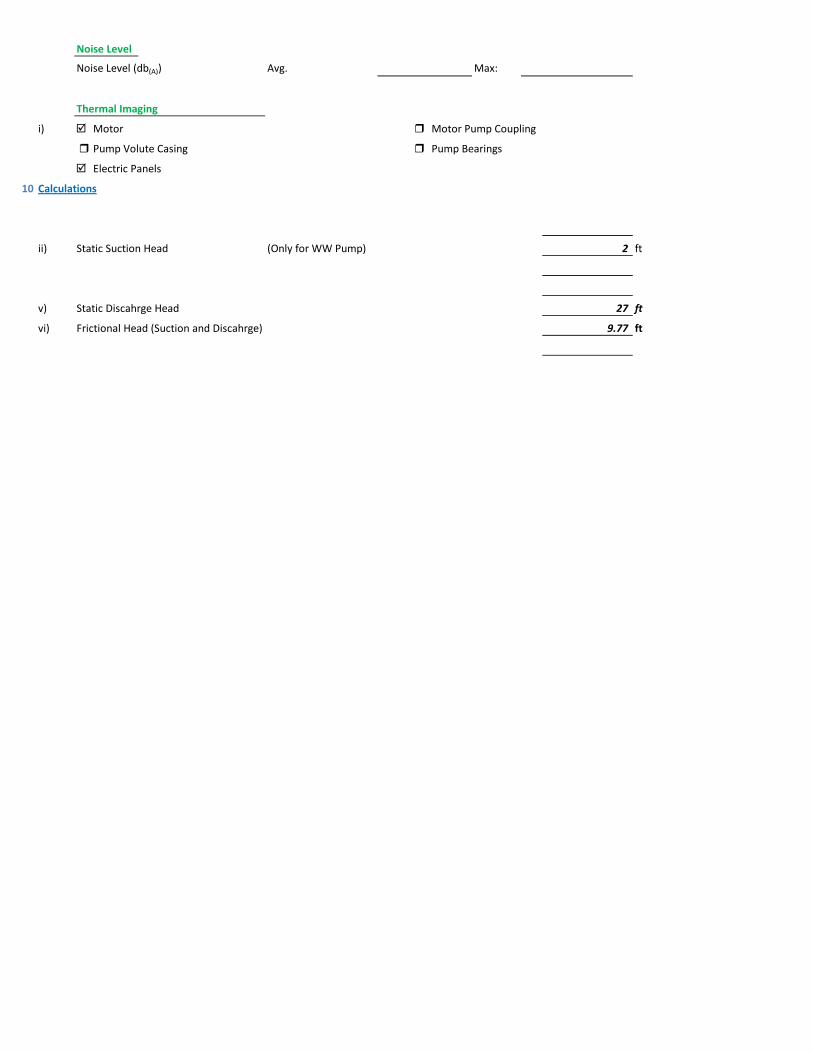
Noise Level
Noise Level (db(A)) Avg. Max:
Thermal Imaging
i) Motor Motor Pump Coupling
Pump Volute Casing Pump Bearings
Electric Panels
10 Calculations
ii) Static Suction Head (Only for WW Pump) 2 ft
v) Static Discahrge Head 27 ft
vi) Frictional Head (Suction and Discahrge) 9.77 ft

viii) Total Dynamic Head of Pump (TDH) 34.77 ft
x) Specific Speed of Pump
Ns = RPM x GPM0.5 / H0.75
impeller rpm necessary to produce 1gpm/ft head 0
500-10,000, standard, 2,000-3,000 high efficiency
xi) Difference of Pump Curve flow and Measured Flow at the TDH m3/hr
xii) Deviation of actual flow from the pump curve flow %
xiii) Water Horsepower (whp) (TDH x Actual Measured Flow) 8.89 hp
xiv) Brake Horsepower (bhp) (OEM Data) 0.00 hp
xv) Electrical Horsepower(ehp) (Electrical Measurement at Motor input) 27.08 hp
xvi) Efficiency of Individual Pump (ηpump) (whp/bhp) x 100 #DIV/0! %
xvii) Efficiency of Pumping System (ηsystem)Existing (whp/ehp) x 100 32.84 %
xviii) Existing Specific Pumping Energy (En(pumping01)) 0.09 kWh/m3
xix) Avg. Cost of Energy (Based on Grid and Backup) 13 PKR/kWh
xx) Daily Operational Time of Pump 15 hrs
xxi) Daily Pump flow 3,450 m3/day
xxii) Annual working days 365 days
xxiii) Annual Pump flow 1,259,250 m3/yr
xxiv) Annual Energy Consumption of Pump (En(pumping01) x Annual Pump Flow) 111,188 kWh/yr
xxv) Annual Energy Expenditure on Pumping 1,445,444 PKR/Yr
xxvi) Pumping System Efficiency after Improvement 59 %
xxvii) Water Flow after Efficiency Improvement 413 m3/hr
xxviii) Specific Energy Consumption at New Efficiency 0.05 kWh/m3
xxix) Potential of Energy Reduction 44.35 %
xxx) Reduced Annual Energy Consumption at Improved Efficiency 49,308 kWh/yr
xxxi) Annual Financial Saving on Pumping 641,007 PKR/Yr
11 Summary of Findings
Pumping system efficiency is 32.84%. For pump attached with 40 HP motor, efficiency below 52.1% is considered to be LOW, (Above 61.9% is EXCELLENT). This pumping system requires impeller adjustment, repair and maintenance. After this adjustment its efficiency will be improved to 59% (GOOD Efficiency range), with annual savings of 641,007 PKR,
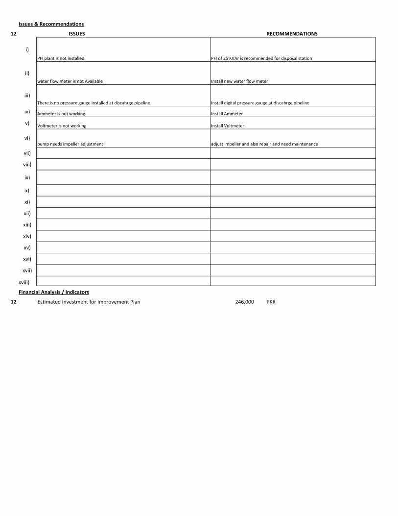
Issues & Recommendations
12 ISSUES RECOMMENDATIONS
i)
ii)
iii)
iv)
v)
vi)
vii)
viii)
ix)
x)
xi)
xii)
xiii)
xiv)
xv)
xvi)
xvii)
xviii)
Financial Analysis / Indicators
12 Estimated Investment for Improvement Plan 246,000 PKR
pump needs impeller adjustment adjust impeller and also repair and need maintenance
PFI plant is not installed PFI of 25 KVAr is recommended for disposal station
Voltmeter is not working
Install AmmeterAmmeter is not working
water flow meter is not Available Install new water flow meter
Install Voltmeter
There is no pressure gauge installed at discahrge pipeline Install digital pressure gauge at discahrge pipeline
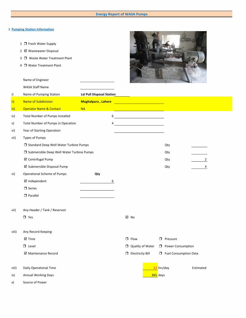
1 Pumping Station Information
1 Fresh Water Supply
2 Wastewater Disposal
3 Waste Water Treatment Plant
4 Water Treatment Plant
Name of Engineer
WASA Staff Name
i) Name of Pumping Station Lal Pull Disposal Station
ii) Name of Subdivision Mughalpura , Lahore
iii) Operator Name & Contact NA
iv) Total Number of Pumps Installed 6
v) Total Number of Pumps in Operation 4
vi) Year of Starting Operation
vii) Types of Pumps
Standard Deep Well Water Turbine Pumps Qty
Submersible Deep Well Water Turbine Pumps Qty
Centrifugal Pump Qty 2
Submersible Disposal Pump Qty 4
vi) Operational Scheme of Pumps Qty
Independent 6
Series
Parallel
vii) Any Header / Tank / Reservoir
Yes No
viii) Any Record Keeping
Time Flow Pressure
Level Quality of Water Power Consumption
Maintenance Record Electricity Bill Fuel Consumption Data
viii) Daily Operational Time 12 hrs/day Estimated
ix) Annual Working Days 365 days
x) Source of Power
Energy Report of WASA Pumps

Primary LESCO Secondary
xi) In Case of Secondary Power Source Fuel Data Details
xii) Operational Hours of Secondary Power Source hrs/day
2 Pump Basic Information Pump # 01
ii) Mounting / Erection
Horizontal Vertical Submersible
Foundation
iii) Concrete Bolted Bolted
iv)
v) Cooling Type
Water Cooled Air Cooled
vi) Number of Stages
Single Multi
vii) Pump and Motor Assembly
Direct Coupled Belt / Gear
viii) Source of Suction
Wet Well Overhead Tank Underground Tank
Pressurized Source
ix) Pump Discharge Destination
Overhead Tank Drain On Ground Reservoir
Pit
Pump Operational Scheme
On / OFF Proportional
x) Pump Flow Control
Throttle VFD Controlled
xi) Any Retrofits ?
Impeller Detail
Casing / Volute Detail
Line Shaft (DW) Detail
Column Sett. (DW) Detail

Motor Replacement Detail
Motor Rewinding Detail
xii) Self Priming
Yes No NA (not applicable)
xiii) Non Clogging (In case of wastewater)
Yes No
xiv) Flowmeter Available
Yes No
xv) Flowmeter Working
Working Properly Malfunctioning (Damaged)
3 Pump Nameplate Data
i) Make / Brand KSB Country Pakistan
ii) Model Serial
iii) Certification Mark
iv) Year of Manufacture
v) Flowrate (Q) 2 Cusec 204 m3/hr
vi) Head (H) ft
vii) Discharge Pressure (P) Psig
viii) Power / HP / BHP BHP
ix) Speed (n) RPM
x) Maximum Pressure (Pmax)
xi) Maxiumum Allowable Temperature
5 Piping System
Suction Side
Select Pipe Material of Construction MS Pipe
i) Enter Diameter of Suction Pipe (In) 6
ii) Enter Length of Suction Pipe (ft) 2
iii) Enter Fittings on Suction Pipe
Fitting Type 1 Qty Type 2 Qty Type 3 Qty
Valves Flow control 1
Bends
Strainer 1
viii) Availbility of Pressure Gauge Yes No
ix) Suction Pressure

Discharge Side
Pipe Material of Construction MS Pipe
i) Diameter of Discharge Pipe (in) 6
ii) Length of Discharge Pipe (ft) 55 Estimated
iii) Fittings on Discharge Pipe
Fitting Type 1 Qty Type 2 Qty Type 3 Qty
Valves Non return 1 1
Bends 1
Strainer
vi) Discharge Elevation (from Datum Line) 37 ft
Suction Side Elevation 2 ft
vii) Availbility of Pressure Gauge Yes No
viii) Discharge Pressure psig
6 Motor Nameplate Data
i) Manufacturer Siemens
ii) Rated kW / hp 20 hp 15 kW
iii) Voltage Range Volts
iv) Current Amperes
v) Power Factor (Cos ɸ)
Standard
Ambient Temp oC
Year of Manufacturing
Efficiency Class
IE3 Eff 1
IE2 Eff 2
IE1 Eff 3
Standard Efficiency
vi) Motor Speed RPM
vii) Reference Frequency 50 Hz
viii) Insulation Class
ix) Motor Frame Size
x)
7 Electrical System Observations
i) Electrical Meter Reference Number
ii) Meter Reading
iii) Meter Time and Date
Correct FALSE

Lag by Lead by
iv) Transformer Rating (kVA) 200 Condition OK
Pump O & M Cost
v) Motor Starting Method
Direct Online Star (Wye) - Delta
Autotransformer Starter Soft Starter
Variable Frequency Drives
v) Electrical Protections Available
Earthing / Grounding Fuses or Miniature Circuit Breaker (MCB)
Earth Leakage Circuit Breaker (ELCB) and Residual Current Circuit Breaker (RCCB)
PFI Plant Not Installed
Panel Condition/Issues Excellent
Gland Leakage
Non Return Valve
Flow Meter not available
Pressure Gauge not available
Wiring fair
Housekeeping
Motor Terminal ok
Foundation/Civil work
Field Measurements
8 Flow Measurement
i) Flow Measurement Location
Discharge Pipe Suction Pipe
ii) Pipe Material of Construction MS Pipe
iii) Paint on Pipe Yes No
iv) Pipe Diameter 6 inches
v) Pipe Perimeter 479 mm
vi) Type of Clamping (V/N/Z) V
viii) Flow Measurement 150 m3/hr 2.5 m3/min
Velocity in Pipe 2.28 m/sec
Pressure
i) Pressure at Discharge Side of Pump psig
ii) Pressure at Suction Side of Pump
ii) Total Length (Suction+Discahrge Pipe) 17 meter
Electric Measurements Volt 381.5 385 382.2
Ampere 24.3 23.8 24.9
kW 13.2 Power Factor 0.82
vi) Motor Working on Loading Basis 88 %
Oversize Undersize Properly Sized
Speed
i) Speed of Motor 0 RPM
ii) Speed of Pump Impeller RPM

Noise Level
Noise Level (db(A)) Avg. Max:
Thermal Imaging
i) Motor Motor Pump Coupling
Pump Volute Casing Pump Bearings
Electric Panels
10 Calculations
ii) Static Suction Head (Only for WW Pump) 2 ft
v) Static Discahrge Head 37 ft
vi) Frictional Head (Suction and Discahrge) 13.74 ft

viii) Total Dynamic Head of Pump (TDH) 48.74 ft
x) Specific Speed of Pump
Ns = RPM x GPM0.5 / H0.75
impeller rpm necessary to produce 1gpm/ft head 0
500-10,000, standard, 2,000-3,000 high efficiency
xi) Difference of Pump Curve flow and Measured Flow at the TDH m3/hr
xii) Deviation of actual flow from the pump curve flow %
xiii) Water Horsepower (whp) (TDH x Actual Measured Flow) 8.13 hp
xiv) Brake Horsepower (bhp) (OEM Data) 0.00 hp
xv) Electrical Horsepower(ehp) (Electrical Measurement at Motor input) 17.69 hp
xvi) Efficiency of Individual Pump (ηpump) (whp/bhp) x 100 #DIV/0! %
xvii) Efficiency of Pumping System (ηsystem)Existing (whp/ehp) x 100 45.94 %
xviii) Existing Specific Pumping Energy (En(pumping01)) 0.09 kWh/m3
xix) Avg. Cost of Energy (Based on Grid and Backup) 13 PKR/kWh
xx) Daily Operational Time of Pump 12 hrs
xxi) Daily Pump flow 1,800 m3/day
xxii) Annual working days 365 days
xxiii) Annual Pump flow 657,000 m3/yr
xxiv) Annual Energy Consumption of Pump (En(pumping01) x Annual Pump Flow) 58,126 kWh/yr
xxv) Annual Energy Expenditure on Pumping 755,638 PKR/Yr
xxvi) Pumping System Efficiency after Improvement 57 %
xxvii) Water Flow after Efficiency Improvement 186 m3/hr
xxviii) Specific Energy Consumption at New Efficiency 0.07 kWh/m3
xxix) Potential of Energy Reduction 19.41 %
xxx) Reduced Annual Energy Consumption at Improved Efficiency 11,281 kWh/yr
xxxi) Annual Financial Saving on Pumping 146,648 PKR/Yr
11 Summary of Findings
Pumping system efficiency is 45.94%. For pump attached with 20 HP motor, efficiency below 48% is considered to be LOW, (Above 60.9% is EXCELLENT). This pumping system requires impeller adjustment, repair and maintenance. After this adjustment its efficiency will be improved to 57% (GOOD Efficiency range), with annual savings of 146,648 PKR,
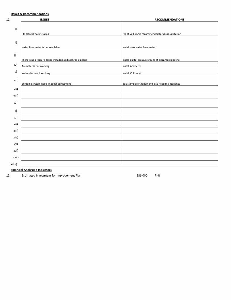
Issues & Recommendations
12 ISSUES RECOMMENDATIONS
i)
ii)
iii)
iv)
v)
vi)
vii)
viii)
ix)
x)
xi)
xii)
xiii)
xiv)
xv)
xvi)
xvii)
xviii)
Financial Analysis / Indicators
12 Estimated Investment for Improvement Plan 286,000 PKR
pumping system need impeller adjustment adjust impeller ,repair and also need maintenance
PFI plant is not installed PFI of 50 KVAr is recommended for disposal station
Voltmeter is not working
Install AmmeterAmmeter is not working
water flow meter is not Available Install new water flow meter
Install Voltmeter
There is no pressure gauge installed at discahrge pipeline Install digital pressure gauge at discahrge pipeline

1 Pumping Station Information
1 Fresh Water Supply
2 Wastewater Disposal
3 Waste Water Treatment Plant
4 Water Treatment Plant
Name of Engineer
WASA Staff Name
i) Name of Pumping Station Lal Pull Disposal Station
ii) Name of Subdivision Mughalpura , Lahore
iii) Operator Name & Contact NA
iv) Total Number of Pumps Installed 6
v) Total Number of Pumps in Operation 4
vi) Year of Starting Operation
vii) Types of Pumps
Standard Deep Well Water Turbine Pumps Qty
Submersible Deep Well Water Turbine Pumps Qty
Centrifugal Pump Qty 2
Submersible Disposal Pump Qty 4
vi) Operational Scheme of Pumps Qty
Independent 6
Series
Parallel
vii) Any Header / Tank / Reservoir
Yes No
viii) Any Record Keeping
Time Flow Pressure
Level Quality of Water Power Consumption
Maintenance Record Electricity Bill Fuel Consumption Data
viii) Daily Operational Time 12 hrs/day Estimated
ix) Annual Working Days 365 days
x) Source of Power
Picture
Energy Report of WASA Pumps

Primary LESCO Secondary
xi) In Case of Secondary Power Source Fuel Data Details
xii) Operational Hours of Secondary Power Source hrs/day
2 Pump Basic Information Pump # 02
ii) Mounting / Erection
Horizontal Vertical Submersible
Foundation
iii) Concrete Bolted Bolted
iv)
v) Cooling Type
Water Cooled Air Cooled
vi) Number of Stages
Single Multi
vii) Pump and Motor Assembly
Direct Coupled Belt / Gear
viii) Source of Suction
Wet Well Overhead Tank Underground Tank
Pressurized Source
ix) Pump Discharge Destination
Overhead Tank Drain On Ground Reservoir
Pit
Pump Operational Scheme
On / OFF Proportional
x) Pump Flow Control
Throttle VFD Controlled
xi) Any Retrofits ?
Impeller Detail
Casing / Volute Detail
Line Shaft (DW) Detail
Column Sett. (DW) Detail
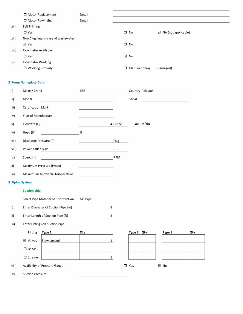
Motor Replacement Detail
Motor Rewinding Detail
xii) Self Priming
Yes No NA (not applicable)
xiii) Non Clogging (In case of wastewater)
Yes No
xiv) Flowmeter Available
Yes No
xv) Flowmeter Working
Working Properly Malfunctioning (Damaged)
3 Pump Nameplate Data
i) Make / Brand KSB Country Pakistan
ii) Model Serial
iii) Certification Mark
iv) Year of Manufacture
v) Flowrate (Q) 4 Cusec 408 m3/hr
vi) Head (H) ft
vii) Discharge Pressure (P) Psig
viii) Power / HP / BHP BHP
ix) Speed (n) RPM
x) Maximum Pressure (Pmax)
xi) Maxiumum Allowable Temperature
5 Piping System
Suction Side
Select Pipe Material of Construction MS Pipe
i) Enter Diameter of Suction Pipe (In) 8
ii) Enter Length of Suction Pipe (ft) 2
iii) Enter Fittings on Suction Pipe
Fitting Type 1 Qty Type 2 Qty Type 3 Qty
Valves Flow control 1
Bends
Strainer 1
viii) Availbility of Pressure Gauge Yes No
ix) Suction Pressure

Discharge Side
Pipe Material of Construction MS Pipe
i) Diameter of Discharge Pipe (in) 8
ii) Length of Discharge Pipe (ft) 55
iii) Fittings on Discharge Pipe
Fitting Type 1 Qty Type 2 Qty Type 3 Qty
Valves Non return 1 1
Bends 1
Strainer
vi) Discharge Elevation (from Datum Line) 37 ft
Suction Side Elevation 2 ft
vii) Availbility of Pressure Gauge Yes No
viii) Discharge Pressure psig
6 Motor Nameplate Data
i) Manufacturer Siemens
ii) Rated kW / hp 40 hp 30 kW
iii) Voltage Range Volts
iv) Current Amperes
v) Power Factor (Cos ɸ)
Standard
Ambient Temp oC
Year of Manufacturing
Efficiency Class
IE3 Eff 1
IE2 Eff 2
IE1 Eff 3
Standard Efficiency
vi) Motor Speed RPM
vii) Reference Frequency 50 Hz
viii) Insulation Class
ix) Motor Frame Size
x)
7 Electrical System Observations
i) Electrical Meter Reference Number
ii) Meter Reading
iii) Meter Time and Date
Correct FALSE

Lag by Lead by
iv) Transformer Rating (kVA) 200 Condition OK
Pump O & M Cost
v) Motor Starting Method
Direct Online Star (Wye) - Delta
Autotransformer Starter Soft Starter
Variable Frequency Drives
v) Electrical Protections Available
Earthing / Grounding Fuses or Miniature Circuit Breaker (MCB)
Earth Leakage Circuit Breaker (ELCB) and Residual Current Circuit Breaker (RCCB)
PFI Plant Not Installed
Panel Condition/Issues Poor
Gland Leakage
Non Return Valve
Flow Meter not available
Pressure Gauge not available
Wiring fair
Housekeeping
Motor Terminal ok
Foundation/Civil work
Field Measurements
8 Flow Measurement
i) Flow Measurement Location
Discharge Pipe Suction Pipe
ii) Pipe Material of Construction MS Pipe
iii) Paint on Pipe Yes No
iv) Pipe Diameter 8 inches
v) Pipe Perimeter 638 mm
vi) Type of Clamping (V/N/Z) V
viii) Flow Measurement 310 m3/hr 5.1667 m3/min
Velocity in Pipe 2.66 m/sec
Pressure
i) Pressure at Discharge Side of Pump psig
ii) Pressure at Suction Side of Pump
ii) Total Length (Suction+Discahrge Pipe) 17 meter
Electric Measurements Volt 380.4 382.8 379.8
Ampere 51.8 53 52.2
kW 27.1 Power Factor 0.78
vi) Motor Working on Loading Basis 91 %
Oversize Undersize Properly Sized
Speed
i) Speed of Motor 0 RPM
ii) Speed of Pump Impeller RPM

Noise Level
Noise Level (db(A)) Avg. Max:
Thermal Imaging
i) Motor Motor Pump Coupling
Pump Volute Casing Pump Bearings
Electric Panels
10 Calculations
ii) Static Suction Head (Only for WW Pump) 2 ft
v) Static Discahrge Head 37 ft
vi) Frictional Head (Suction and Discahrge) 17.94 ft

viii) Total Dynamic Head of Pump (TDH) 52.94 ft
x) Specific Speed of Pump
Ns = RPM x GPM0.5 / H0.75
impeller rpm necessary to produce 1gpm/ft head 0
500-10,000, standard, 2,000-3,000 high efficiency
xi) Difference of Pump Curve flow and Measured Flow at the TDH m3/hr
xii) Deviation of actual flow from the pump curve flow %
xiii) Water Horsepower (whp) (TDH x Actual Measured Flow) 18.25 hp
xiv) Brake Horsepower (bhp) (OEM Data) 0.00 hp
xv) Electrical Horsepower(ehp) (Electrical Measurement at Motor input) 36.33 hp
xvi) Efficiency of Individual Pump (ηpump) (whp/bhp) x 100 #DIV/0! %
xvii) Efficiency of Pumping System (ηsystem)Existing (whp/ehp) x 100 50.23 %
xviii) Existing Specific Pumping Energy (En(pumping01)) 0.09 kWh/m3
xix) Avg. Cost of Energy (Based on Grid and Backup) 13 PKR/kWh
xx) Daily Operational Time of Pump 12 hrs
xxi) Daily Pump flow 3,720 m3/day
xxii) Annual working days 365 days
xxiii) Annual Pump flow 1,357,800 m3/yr
xxiv) Annual Energy Consumption of Pump (En(pumping01) x Annual Pump Flow) 119,334 kWh/yr
xxv) Annual Energy Expenditure on Pumping 1,551,348 PKR/Yr
xxvi) Pumping System Efficiency after Improvement 59 %
xxvii) Water Flow after Efficiency Improvement 364 m3/hr
xxviii) Specific Energy Consumption at New Efficiency 0.07 kWh/m3
xxix) Potential of Energy Reduction 14.86 %
xxx) Reduced Annual Energy Consumption at Improved Efficiency 17,733 kWh/yr
xxxi) Annual Financial Saving on Pumping 230,523 PKR/Yr
11 Summary of Findings
Pumping system efficiency is 50.23%. For pump attached with 40 HP motor, efficiency < 52.1% is considered to be LOW, (above 61.9% is EXCELLENT). This pumping system requires impeller adjustment which will improve efficiency to 59% with annual savings of 230,523 PKR.

Issues & Recommendations
12 ISSUES RECOMMENDATIONS
i)
ii)
iii)
iv)
v)
vi)
vii)
viii)
ix)
x)
xi)
xii)
xiii)
xiv)
xv)
xvi)
xvii)
xviii)
Financial Analysis / Indicators
12 Estimated Investment for Improvement Plan 86,000 PKR
pumping system need impeller adjustment adjust impeller
There is no pressure gauge installed at discahrge pipeline Install digital pressure gauge at discahrge pipeline
PFI plant is not installed PFI of 50 KVAr is recommended for disposal station
Voltmeter is not working
Install AmmeterAmmeter is not working
water flow meter is not Available Install new water flow meter
Install Voltmeter
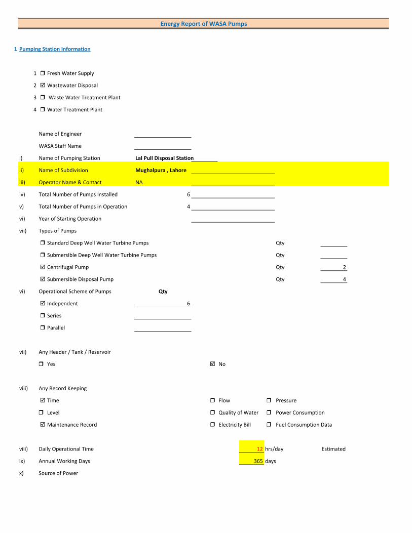
1 Pumping Station Information
1 Fresh Water Supply
2 Wastewater Disposal
3 Waste Water Treatment Plant
4 Water Treatment Plant
Name of Engineer
WASA Staff Name
i) Name of Pumping Station Lal Pull Disposal Station
ii) Name of Subdivision Mughalpura , Lahore
iii) Operator Name & Contact NA
iv) Total Number of Pumps Installed 6
v) Total Number of Pumps in Operation 4
vi) Year of Starting Operation
vii) Types of Pumps
Standard Deep Well Water Turbine Pumps Qty
Submersible Deep Well Water Turbine Pumps Qty
Centrifugal Pump Qty 2
Submersible Disposal Pump Qty 4
vi) Operational Scheme of Pumps Qty
Independent 6
Series
Parallel
vii) Any Header / Tank / Reservoir
Yes No
viii) Any Record Keeping
Time Flow Pressure
Level Quality of Water Power Consumption
Maintenance Record Electricity Bill Fuel Consumption Data
viii) Daily Operational Time 12 hrs/day Estimated
ix) Annual Working Days 365 days
x) Source of Power
Energy Report of WASA Pumps

Primary LESCO Secondary
xi) In Case of Secondary Power Source Fuel Data Details
xii) Operational Hours of Secondary Power Source hrs/day
2 Pump Basic Information Pump # 05
ii) Mounting / Erection
Horizontal Vertical Submersible
Foundation
iii) Concrete Bolted Bolted
iv)
v) Cooling Type
Water Cooled Air Cooled
vi) Number of Stages
Single Multi
vii) Pump and Motor Assembly
Direct Coupled Belt / Gear
viii) Source of Suction
Wet Well Overhead Tank Underground Tank
Pressurized Source
ix) Pump Discharge Destination
Overhead Tank Drain On Ground Reservoir
Pit
Pump Operational Scheme
On / OFF Proportional
x) Pump Flow Control
Throttle VFD Controlled
xi) Any Retrofits ?
Impeller Detail
Casing / Volute Detail
Line Shaft (DW) Detail
Column Sett. (DW) Detail

Motor Replacement Detail
Motor Rewinding Detail
xii) Self Priming
Yes No NA (not applicable)
xiii) Non Clogging (In case of wastewater)
Yes No
xiv) Flowmeter Available
Yes No
xv) Flowmeter Working
Working Properly Malfunctioning (Damaged)
3 Pump Nameplate Data
i) Make / Brand KSB Country Pakistan
ii) Model Serial
iii) Certification Mark
iv) Year of Manufacture
v) Flowrate (Q) 2 Cusec 204 m3/hr
vi) Head (H) ft
vii) Discharge Pressure (P) Psig
viii) Power / HP / BHP BHP
ix) Speed (n) RPM
x) Maximum Pressure (Pmax)
xi) Maxiumum Allowable Temperature
5 Piping System
Suction Side
Select Pipe Material of Construction MS Pipe
i) Enter Diameter of Suction Pipe (In) 6
ii) Enter Length of Suction Pipe (ft) 2
iii) Enter Fittings on Suction Pipe
Fitting Type 1 Qty Type 2 Qty Type 3 Qty
Valves Flow control 1
Bends
Strainer 1
viii) Availbility of Pressure Gauge Yes No
ix) Suction Pressure

Discharge Side
Pipe Material of Construction MS Pipe
i) Diameter of Discharge Pipe (in) 6
ii) Length of Discharge Pipe (ft) 55
iii) Fittings on Discharge Pipe
Fitting Type 1 Qty Type 2 Qty Type 3 Qty
Valves Non return 1 1
Bends 1
Strainer
vi) Discharge Elevation (from Datum Line) 37 ft
Suction Side Elevation 2 ft
vii) Availbility of Pressure Gauge Yes No
viii) Discharge Pressure psig
6 Motor Nameplate Data
i) Manufacturer Siemens
ii) Rated kW / hp 20 hp 15 kW
iii) Voltage Range Volts
iv) Current Amperes
v) Power Factor (Cos ɸ)
Standard
Ambient Temp oC
Year of Manufacturing
Efficiency Class
IE3 Eff 1
IE2 Eff 2
IE1 Eff 3
Standard Efficiency
vi) Motor Speed RPM
vii) Reference Frequency 50 Hz
viii) Insulation Class
ix) Motor Frame Size
x)
7 Electrical System Observations
i) Electrical Meter Reference Number
ii) Meter Reading
iii) Meter Time and Date
Correct FALSE

Lag by Lead by
iv) Transformer Rating (kVA) 200 Condition OK
Pump O & M Cost
v) Motor Starting Method
Direct Online Star (Wye) - Delta
Autotransformer Starter Soft Starter
Variable Frequency Drives
v) Electrical Protections Available
Earthing / Grounding Fuses or Miniature Circuit Breaker (MCB)
Earth Leakage Circuit Breaker (ELCB) and Residual Current Circuit Breaker (RCCB)
PFI Plant Not Installed
Panel Condition/Issues Excellent
Gland Leakage
Non Return Valve
Flow Meter not available
Pressure Gauge not available
Wiring fair
Housekeeping
Motor Terminal ok
Foundation/Civil work
Field Measurements
8 Flow Measurement
i) Flow Measurement Location
Discharge Pipe Suction Pipe
ii) Pipe Material of Construction MS Pipe
iii) Paint on Pipe Yes No
iv) Pipe Diameter 6 inches
v) Pipe Perimeter 479 mm
vi) Type of Clamping (V/N/Z) V
viii) Flow Measurement 158 m3/hr 2.6333 m3/min
Velocity in Pipe 2.41 m/sec
Pressure
i) Pressure at Discharge Side of Pump psig
ii) Pressure at Suction Side of Pump
ii) Total Length (Suction+Discahrge Pipe) 17 meter
Electric Measurements Volt 390.1 387.8 388.4
Ampere 23.5 24.8 26.1
kW 14 Power Factor 0.84
vi) Motor Working on Loading Basis 94 %
Oversize Undersize Properly Sized
Speed
i) Speed of Motor 0 RPM
ii) Speed of Pump Impeller RPM

Noise Level
Noise Level (db(A)) Avg. Max:
Thermal Imaging
i) Motor Motor Pump Coupling
Pump Volute Casing Pump Bearings
Electric Panels
10 Calculations
ii) Static Suction Head (Only for WW Pump) 2 ft
v) Static Discahrge Head 37 ft
vi) Frictional Head (Suction and Discahrge) 15.23 ft

viii) Total Dynamic Head of Pump (TDH) 50.23 ft
x) Specific Speed of Pump
Ns = RPM x GPM0.5 / H0.75
impeller rpm necessary to produce 1gpm/ft head 0
500-10,000, standard, 2,000-3,000 high efficiency
xi) Difference of Pump Curve flow and Measured Flow at the TDH m3/hr
xii) Deviation of actual flow from the pump curve flow %
xiii) Water Horsepower (whp) (TDH x Actual Measured Flow) 8.82 hp
xiv) Brake Horsepower (bhp) (OEM Data) 0.00 hp
xv) Electrical Horsepower(ehp) (Electrical Measurement at Motor input) 18.77 hp
xvi) Efficiency of Individual Pump (ηpump) (whp/bhp) x 100 #DIV/0! %
xvii) Efficiency of Pumping System (ηsystem)Existing (whp/ehp) x 100 47.02 %
xviii) Existing Specific Pumping Energy (En(pumping01)) 0.09 kWh/m3
xix) Avg. Cost of Energy (Based on Grid and Backup) 13 PKR/kWh
xx) Daily Operational Time of Pump 12 hrs
xxi) Daily Pump flow 1,896 m3/day
xxii) Annual working days 365 days
xxiii) Annual Pump flow 692,040 m3/yr
xxiv) Annual Energy Consumption of Pump (En(pumping01) x Annual Pump Flow) 61,649 kWh/yr
xxv) Annual Energy Expenditure on Pumping 801,434 PKR/Yr
xxvi) Pumping System Efficiency after Improvement 57 %
xxvii) Water Flow after Efficiency Improvement 192 m3/hr
xxviii) Specific Energy Consumption at New Efficiency 0.07 kWh/m3
xxix) Potential of Energy Reduction 17.51 %
xxx) Reduced Annual Energy Consumption at Improved Efficiency 10,795 kWh/yr
xxxi) Annual Financial Saving on Pumping 140,337 PKR/Yr
11 Summary of Findings
Pumping system efficiency is 47.02%. For pump attached with 40 HP motor, efficiency < 52.1% is considered to be LOW, (above 61.9% is EXCELLENT). This pumping system requires impeller adjustment and repair and maintenance which will improve efficiency to 59% with annual savings of 140,337 PKR.
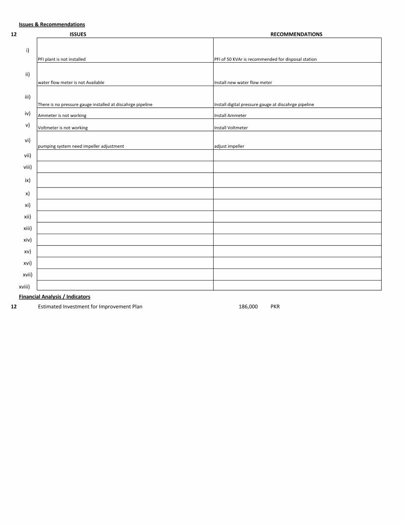
Issues & Recommendations
12 ISSUES RECOMMENDATIONS
i)
ii)
iii)
iv)
v)
vi)
vii)
viii)
ix)
x)
xi)
xii)
xiii)
xiv)
xv)
xvi)
xvii)
xviii)
Financial Analysis / Indicators
12 Estimated Investment for Improvement Plan 186,000 PKR
Voltmeter is not working
Install AmmeterAmmeter is not working
water flow meter is not Available Install new water flow meter
Install Voltmeter
There is no pressure gauge installed at discahrge pipeline Install digital pressure gauge at discahrge pipeline
PFI plant is not installed PFI of 50 KVAr is recommended for disposal station
pumping system need impeller adjustment adjust impeller
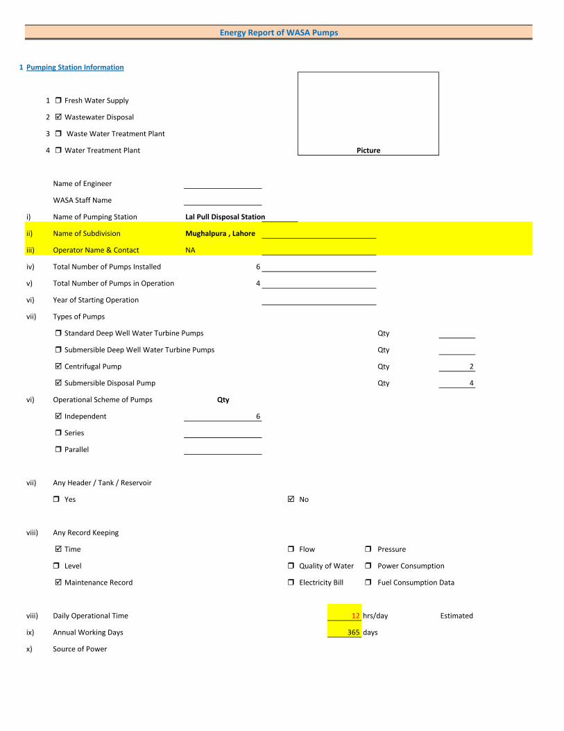
1 Pumping Station Information
1 Fresh Water Supply
2 Wastewater Disposal
3 Waste Water Treatment Plant
4 Water Treatment Plant
Name of Engineer
WASA Staff Name
i) Name of Pumping Station Lal Pull Disposal Station
ii) Name of Subdivision Mughalpura , Lahore
iii) Operator Name & Contact NA
iv) Total Number of Pumps Installed 6
v) Total Number of Pumps in Operation 4
vi) Year of Starting Operation
vii) Types of Pumps
Standard Deep Well Water Turbine Pumps Qty
Submersible Deep Well Water Turbine Pumps Qty
Centrifugal Pump Qty 2
Submersible Disposal Pump Qty 4
vi) Operational Scheme of Pumps Qty
Independent 6
Series
Parallel
vii) Any Header / Tank / Reservoir
Yes No
viii) Any Record Keeping
Time Flow Pressure
Level Quality of Water Power Consumption
Maintenance Record Electricity Bill Fuel Consumption Data
viii) Daily Operational Time 12 hrs/day Estimated
ix) Annual Working Days 365 days
x) Source of Power
Picture
Energy Report of WASA Pumps

Primary LESCO Secondary
xi) In Case of Secondary Power Source Fuel Data Details
xii) Operational Hours of Secondary Power Source hrs/day
2 Pump Basic Information Pump # 06
ii) Mounting / Erection
Horizontal Vertical Submersible
Foundation
iii) Concrete Bolted Bolted
iv)
v) Cooling Type
Water Cooled Air Cooled
vi) Number of Stages
Single Multi
vii) Pump and Motor Assembly
Direct Coupled Belt / Gear
viii) Source of Suction
Wet Well Overhead Tank Underground Tank
Pressurized Source
ix) Pump Discharge Destination
Overhead Tank Drain On Ground Reservoir
Pit
Pump Operational Scheme
On / OFF Proportional
x) Pump Flow Control
Throttle VFD Controlled
xi) Any Retrofits ?
Impeller Detail
Casing / Volute Detail
Line Shaft (DW) Detail
Column Sett. (DW) Detail

Motor Replacement Detail
Motor Rewinding Detail
xii) Self Priming
Yes No NA (not applicable)
xiii) Non Clogging (In case of wastewater)
Yes No
xiv) Flowmeter Available
Yes No
xv) Flowmeter Working
Working Properly Malfunctioning (Damaged)
3 Pump Nameplate Data
i) Make / Brand KSB Country Pakistan
ii) Model Serial
iii) Certification Mark
iv) Year of Manufacture
v) Flowrate (Q) 4 Cusec 408 m3/hr
vi) Head (H) ft
vii) Discharge Pressure (P) Psig
viii) Power / HP / BHP BHP
ix) Speed (n) RPM
x) Maximum Pressure (Pmax)
xi) Maxiumum Allowable Temperature
5 Piping System
Suction Side
Select Pipe Material of Construction MS Pipe
i) Enter Diameter of Suction Pipe (In) 8
ii) Enter Length of Suction Pipe (ft) 2
iii) Enter Fittings on Suction Pipe
Fitting Type 1 Qty Type 2 Qty Type 3 Qty
Valves Flow control 1
Bends
Strainer 1
viii) Availbility of Pressure Gauge Yes No
ix) Suction Pressure

Discharge Side
Pipe Material of Construction MS Pipe
i) Diameter of Discharge Pipe (in) 8
ii) Length of Discharge Pipe (ft) 55
iii) Fittings on Discharge Pipe
Fitting Type 1 Qty Type 2 Qty Type 3 Qty
Valves Non return 1 1
Bends 1
Strainer
vi) Discharge Elevation (from Datum Line) 37 ft
Suction Side Elevation 2 ft
vii) Availbility of Pressure Gauge Yes No
viii) Discharge Pressure psig
6 Motor Nameplate Data
i) Manufacturer Siemens
ii) Rated kW / hp 40 hp 30 kW
iii) Voltage Range Volts
iv) Current Amperes
v) Power Factor (Cos ɸ)
Standard
Ambient Temp oC
Year of Manufacturing
Efficiency Class
IE3 Eff 1
IE2 Eff 2
IE1 Eff 3
Standard Efficiency
vi) Motor Speed RPM
vii) Reference Frequency 50 Hz
viii) Insulation Class
ix) Motor Frame Size
x)
7 Electrical System Observations
i) Electrical Meter Reference Number
ii) Meter Reading
iii) Meter Time and Date
Correct FALSE
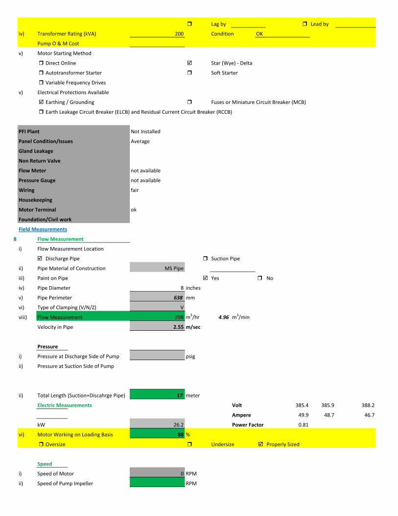
Lag by Lead by
iv) Transformer Rating (kVA) 200 Condition OK
Pump O & M Cost
v) Motor Starting Method
Direct Online Star (Wye) - Delta
Autotransformer Starter Soft Starter
Variable Frequency Drives
v) Electrical Protections Available
Earthing / Grounding Fuses or Miniature Circuit Breaker (MCB)
Earth Leakage Circuit Breaker (ELCB) and Residual Current Circuit Breaker (RCCB)
PFI Plant Not Installed
Panel Condition/Issues Average
Gland Leakage
Non Return Valve
Flow Meter not available
Pressure Gauge not available
Wiring fair
Housekeeping
Motor Terminal ok
Foundation/Civil work
Field Measurements
8 Flow Measurement
i) Flow Measurement Location
Discharge Pipe Suction Pipe
ii) Pipe Material of Construction MS Pipe
iii) Paint on Pipe Yes No
iv) Pipe Diameter 8 inches
v) Pipe Perimeter 638 mm
vi) Type of Clamping (V/N/Z) V
viii) Flow Measurement 298 m3/hr 4.96 m3/min
Velocity in Pipe 2.55 m/sec
Pressure
i) Pressure at Discharge Side of Pump psig
ii) Pressure at Suction Side of Pump
ii) Total Length (Suction+Discahrge Pipe) 17 meter
Electric Measurements Volt 385.4 385.9 388.2
Ampere 49.9 48.7 46.7
kW 26.2 Power Factor 0.81
vi) Motor Working on Loading Basis 88 %
Oversize Undersize Properly Sized
Speed
i) Speed of Motor 0 RPM
ii) Speed of Pump Impeller RPM

Noise Level
Noise Level (db(A)) Avg. Max:
Thermal Imaging
i) Motor Motor Pump Coupling
Pump Volute Casing Pump Bearings
Electric Panels
10 Calculations
ii) Static Suction Head (Only for WW Pump) 2 ft
v) Static Discahrge Head 37 ft
vi) Frictional Head (Suction and Discahrge) 16.54 ft
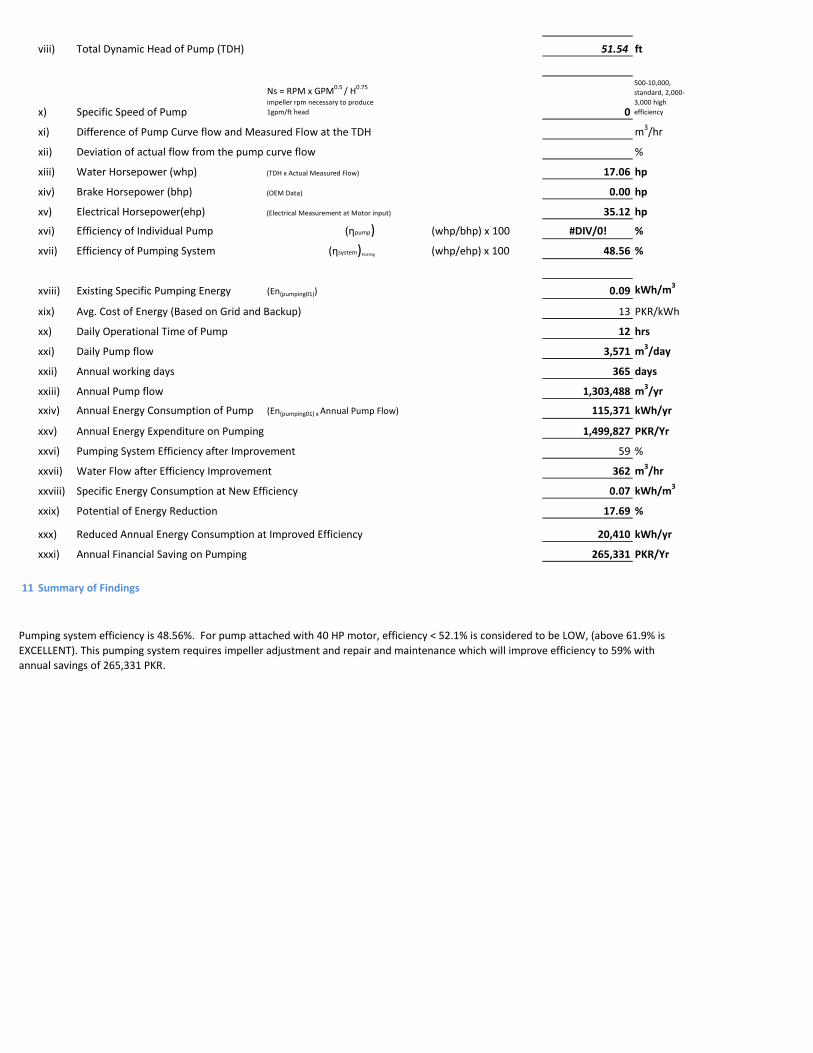
viii) Total Dynamic Head of Pump (TDH) 51.54 ft
x) Specific Speed of Pump
Ns = RPM x GPM0.5 / H0.75
impeller rpm necessary to produce 1gpm/ft head 0
500-10,000, standard, 2,000-3,000 high efficiency
xi) Difference of Pump Curve flow and Measured Flow at the TDH m3/hr
xii) Deviation of actual flow from the pump curve flow %
xiii) Water Horsepower (whp) (TDH x Actual Measured Flow) 17.06 hp
xiv) Brake Horsepower (bhp) (OEM Data) 0.00 hp
xv) Electrical Horsepower(ehp) (Electrical Measurement at Motor input) 35.12 hp
xvi) Efficiency of Individual Pump (ηpump) (whp/bhp) x 100 #DIV/0! %
xvii) Efficiency of Pumping System (ηsystem)Existing (whp/ehp) x 100 48.56 %
xviii) Existing Specific Pumping Energy (En(pumping01)) 0.09 kWh/m3
xix) Avg. Cost of Energy (Based on Grid and Backup) 13 PKR/kWh
xx) Daily Operational Time of Pump 12 hrs
xxi) Daily Pump flow 3,571 m3/day
xxii) Annual working days 365 days
xxiii) Annual Pump flow 1,303,488 m3/yr
xxiv) Annual Energy Consumption of Pump (En(pumping01) x Annual Pump Flow) 115,371 kWh/yr
xxv) Annual Energy Expenditure on Pumping 1,499,827 PKR/Yr
xxvi) Pumping System Efficiency after Improvement 59 %
xxvii) Water Flow after Efficiency Improvement 362 m3/hr
xxviii) Specific Energy Consumption at New Efficiency 0.07 kWh/m3
xxix) Potential of Energy Reduction 17.69 %
xxx) Reduced Annual Energy Consumption at Improved Efficiency 20,410 kWh/yr
xxxi) Annual Financial Saving on Pumping 265,331 PKR/Yr
11 Summary of Findings
Pumping system efficiency is 48.56%. For pump attached with 40 HP motor, efficiency < 52.1% is considered to be LOW, (above 61.9% is EXCELLENT). This pumping system requires impeller adjustment and repair and maintenance which will improve efficiency to 59% with annual savings of 265,331 PKR.

Issues & Recommendations
12 ISSUES RECOMMENDATIONS
i)
ii)
iii)
iv)
v)
vi)
vii)
viii)
ix)
x)
xi)
xii)
xiii)
xiv)
xv)
xvi)
xvii)
xviii)
Financial Analysis / Indicators
12 Estimated Investment for Improvement Plan 186,000 PKR
Pumping system need impeller adjustment adjust impeller
There is no pressure gauge installed at discahrge pipeline Install digital pressure gauge at discahrge pipeline
PFI plant is not installed PFI of 50 KVAr is recommended for disposal station
Voltmeter is not working
Install AmmeterAmmeter is not working
water flow meter is not Available Install new water flow meter
Install Voltmeter

1 Pumping Station Information
1 Fresh Water Supply
2 Wastewater Disposal
3 Waste Water Treatment Plant
4 Water Treatment Plant
Name of Engineer
WASA Staff Name
i) Name of Pumping Station Achant Garh-II Disposal Station
ii) Name of Subdivision Mughalpura , Lahore
iii) Operator Name & Contact M Amjad
iv) Total Number of Pumps Installed 2
v) Total Number of Pumps in Operation 2
vi) Year of Starting Operation
vii) Types of Pumps
Standard Deep Well Water Turbine Pumps Qty
Submersible Deep Well Water Turbine Pumps Qty
Centrifugal Pump Qty 1
Submersible Disposal Pump Qty 1
vi) Operational Scheme of Pumps Qty
Independent 2
Series
Parallel
vii) Any Header / Tank / Reservoir
Yes No
viii) Any Record Keeping
Time Flow Pressure
Level Quality of Water Power Consumption
Maintenance Record Electricity Bill Fuel Consumption Data
viii) Daily Operational Time 12 hrs/day Estimated
ix) Annual Working Days 365 days
x) Source of Power
Energy Report of WASA Pumps

Primary LESCO Secondary
xi) In Case of Secondary Power Source Fuel Data Details
xii) Operational Hours of Secondary Power Source hrs/day
2 Pump Basic Information Pump # 01
ii) Mounting / Erection
Horizontal Vertical Submersible
Foundation
iii) Concrete Bolted Bolted
iv)
v) Cooling Type
Water Cooled Air Cooled
vi) Number of Stages
Single Multi
vii) Pump and Motor Assembly
Direct Coupled Belt / Gear
viii) Source of Suction
Wet Well Overhead Tank Underground Tank
Pressurized Source
ix) Pump Discharge Destination
Overhead Tank Drain On Ground Reservoir
Pit
Pump Operational Scheme
On / OFF Proportional
x) Pump Flow Control
Throttle VFD Controlled
xi) Any Retrofits ?
Impeller Detail
Casing / Volute Detail
Line Shaft (DW) Detail
Column Sett. (DW) Detail

Motor Replacement Detail
Motor Rewinding Detail
xii) Self Priming
Yes No NA (not applicable)
xiii) Non Clogging (In case of wastewater)
Yes No
xiv) Flowmeter Available
Yes No
xv) Flowmeter Working
Working Properly Malfunctioning (Damaged)
3 Pump Nameplate Data
i) Make / Brand KSB Country Pakistan
ii) Model Serial
iii) Certification Mark
iv) Year of Manufacture
v) Flowrate (Q) 2 Cusec 204 m3/hr
vi) Head (H) ft
vii) Discharge Pressure (P) Psig
viii) Power / HP / BHP BHP
ix) Speed (n) RPM
x) Maximum Pressure (Pmax)
xi) Maxiumum Allowable Temperature
5 Piping System
Suction Side
Select Pipe Material of Construction MS Pipe
i) Enter Diameter of Suction Pipe (In) 6
ii) Enter Length of Suction Pipe (ft) 2
iii) Enter Fittings on Suction Pipe
Fitting Type 1 Qty Type 2 Qty Type 3 Qty
Valves Flow control 1
Bends
Strainer 1
viii) Availbility of Pressure Gauge Yes No
ix) Suction Pressure

Discharge Side
Pipe Material of Construction MS Pipe
i) Diameter of Discharge Pipe (in) 6
ii) Length of Discharge Pipe (ft) 38
iii) Fittings on Discharge Pipe
Fitting Type 1 Qty Type 2 Qty Type 3 Qty
Valves Non return 1 1
Bends 1
Strainer
vi) Discharge Elevation (from Datum Line) 18 ft
Suction Side Elevation 2 ft
vii) Availbility of Pressure Gauge Yes No
viii) Discharge Pressure psig
6 Motor Nameplate Data
i) Manufacturer Siemens
ii) Rated kW / hp 20 hp 15 kW
iii) Voltage Range Volts
iv) Current Amperes
v) Power Factor (Cos ɸ)
Standard
Ambient Temp oC
Year of Manufacturing
Efficiency Class
IE3 Eff 1
IE2 Eff 2
IE1 Eff 3
Standard Efficiency
vi) Motor Speed RPM
vii) Reference Frequency 50 Hz
viii) Insulation Class
ix) Motor Frame Size
x)
7 Electrical System Observations
i) Electrical Meter Reference Number
ii) Meter Reading
iii) Meter Time and Date
Correct FALSE

Lag by Lead by
iv) Transformer Rating (kVA) 50 Condition OK
Pump O & M Cost
v) Motor Starting Method
Direct Online Star (Wye) - Delta
Autotransformer Starter Soft Starter
Variable Frequency Drives
v) Electrical Protections Available
Earthing / Grounding Fuses or Miniature Circuit Breaker (MCB)
Earth Leakage Circuit Breaker (ELCB) and Residual Current Circuit Breaker (RCCB)
PFI Plant Not Installed
Panel Condition/Issues Average
Gland Leakage
Non Return Valve
Flow Meter not available
Pressure Gauge not available
Wiring fair
Housekeeping
Motor Terminal ok
Foundation/Civil work
Field Measurements
8 Flow Measurement
i) Flow Measurement Location
Discharge Pipe Suction Pipe
ii) Pipe Material of Construction MS Pipe
iii) Paint on Pipe Yes No
iv) Pipe Diameter 6 inches
v) Pipe Perimeter 479 mm
vi) Type of Clamping (V/N/Z) V
viii) Flow Measurement 185 m3/hr 3.0833 m3/min
Velocity in Pipe 2.82 m/sec
Pressure
i) Pressure at Discharge Side of Pump psig
ii) Pressure at Suction Side of Pump
ii) Total Length (Suction+Discahrge Pipe) 12 meter
Electric Measurements Volt 385.4 380.7 379.8
Ampere 25.6 23.2 26.2
kW 12.2 Power Factor 0.74
vi) Motor Working on Loading Basis 82 %
Oversize Undersize Properly Sized
Speed
i) Speed of Motor 0 RPM
ii) Speed of Pump Impeller RPM

Noise Level
Noise Level (db(A)) Avg. Max:
Thermal Imaging
i) Motor Motor Pump Coupling
Pump Volute Casing Pump Bearings
Electric Panels
10 Calculations
ii) Static Suction Head (Only for WW Pump) 2 ft
v) Static Discahrge Head 18 ft
vi) Frictional Head (Suction and Discahrge) 20.15 ft

viii) Total Dynamic Head of Pump (TDH) 36.15 ft
x) Specific Speed of Pump
Ns = RPM x GPM0.5 / H0.75
impeller rpm necessary to produce 1gpm/ft head 0
500-10,000, standard, 2,000-3,000 high efficiency
xi) Difference of Pump Curve flow and Measured Flow at the TDH m3/hr
xii) Deviation of actual flow from the pump curve flow %
xiii) Water Horsepower (whp) (TDH x Actual Measured Flow) 7.44 hp
xiv) Brake Horsepower (bhp) (OEM Data) 0.00 hp
xv) Electrical Horsepower(ehp) (Electrical Measurement at Motor input) 16.35 hp
xvi) Efficiency of Individual Pump (ηpump) (whp/bhp) x 100 #DIV/0! %
xvii) Efficiency of Pumping System (ηsystem)Existing (whp/ehp) x 100 45.47 %
xviii) Existing Specific Pumping Energy (En(pumping01)) 0.07 kWh/m3
xix) Avg. Cost of Energy (Based on Grid and Backup) 13 PKR/kWh
xx) Daily Operational Time of Pump 12 hrs
xxi) Daily Pump flow 2,220 m3/day
xxii) Annual working days 365 days
xxiii) Annual Pump flow 810,300 m3/yr
xxiv) Annual Energy Consumption of Pump (En(pumping01) x Annual Pump Flow) 53,723 kWh/yr
xxv) Annual Energy Expenditure on Pumping 698,393 PKR/Yr
xxvi) Pumping System Efficiency after Improvement 57 %
xxvii) Water Flow after Efficiency Improvement 232 m3/hr
xxviii) Specific Energy Consumption at New Efficiency 0.05 kWh/m3
xxix) Potential of Energy Reduction 20.22 %
xxx) Reduced Annual Energy Consumption at Improved Efficiency 10,864 kWh/yr
xxxi) Annual Financial Saving on Pumping 141,238 PKR/Yr
11 Summary of Findings
Pumping system efficiency is 45.47%. For pump attached with 20 HP motor, efficiency <48% is considered to be LOW, (above 60.9% is EXCELLENT). This pumping system requires impeller adjustment & also need maintenence which will improve efficiency from 45.47% to 57% with annual savings of 153,403 PKR.

Issues & Recommendations
12 ISSUES RECOMMENDATIONS
i)
ii)
iii)
iv)
v)
vi)
vii)
viii)
ix)
x)
xi)
xii)
xiii)
xiv)
xv)
xvi)
xvii)
xviii)
Financial Analysis / Indicators
12 Estimated Investment for Improvement Plan 216,000 PKR
pumping system need impeller adjustment Adjust impeller and also need maintenance
PFI plant is not installed PFI of 12.5 KVAr is recommended for disposal station
Voltmeter is not working
Install AmmeterAmmeter is not working
water flow meter is not Available Install new water flow meter
Install Voltmeter
There is no pressure gauge installed at discahrge pipeline Install digital pressure gauge at discahrge pipeline

1 Pumping Station Information
1 Fresh Water Supply
2 Wastewater Disposal
3 Waste Water Treatment Plant
4 Water Treatment Plant
Name of Engineer
WASA Staff Name
i) Name of Pumping Station Achant Garh-II Disposal Station
ii) Name of Subdivision Mughalpura , Lahore
iii) Operator Name & Contact M Amjad
iv) Total Number of Pumps Installed 2
v) Total Number of Pumps in Operation 2
vi) Year of Starting Operation
vii) Types of Pumps
Standard Deep Well Water Turbine Pumps Qty
Submersible Deep Well Water Turbine Pumps Qty
Centrifugal Pump Qty 1
Submersible Disposal Pump Qty 1
vi) Operational Scheme of Pumps Qty
Independent 2
Series
Parallel
vii) Any Header / Tank / Reservoir
Yes No
viii) Any Record Keeping
Time Flow Pressure
Level Quality of Water Power Consumption
Maintenance Record Electricity Bill Fuel Consumption Data
viii) Daily Operational Time 12 hrs/day Estimated
ix) Annual Working Days 365 days
x) Source of Power
Energy Report of WASA Pumps
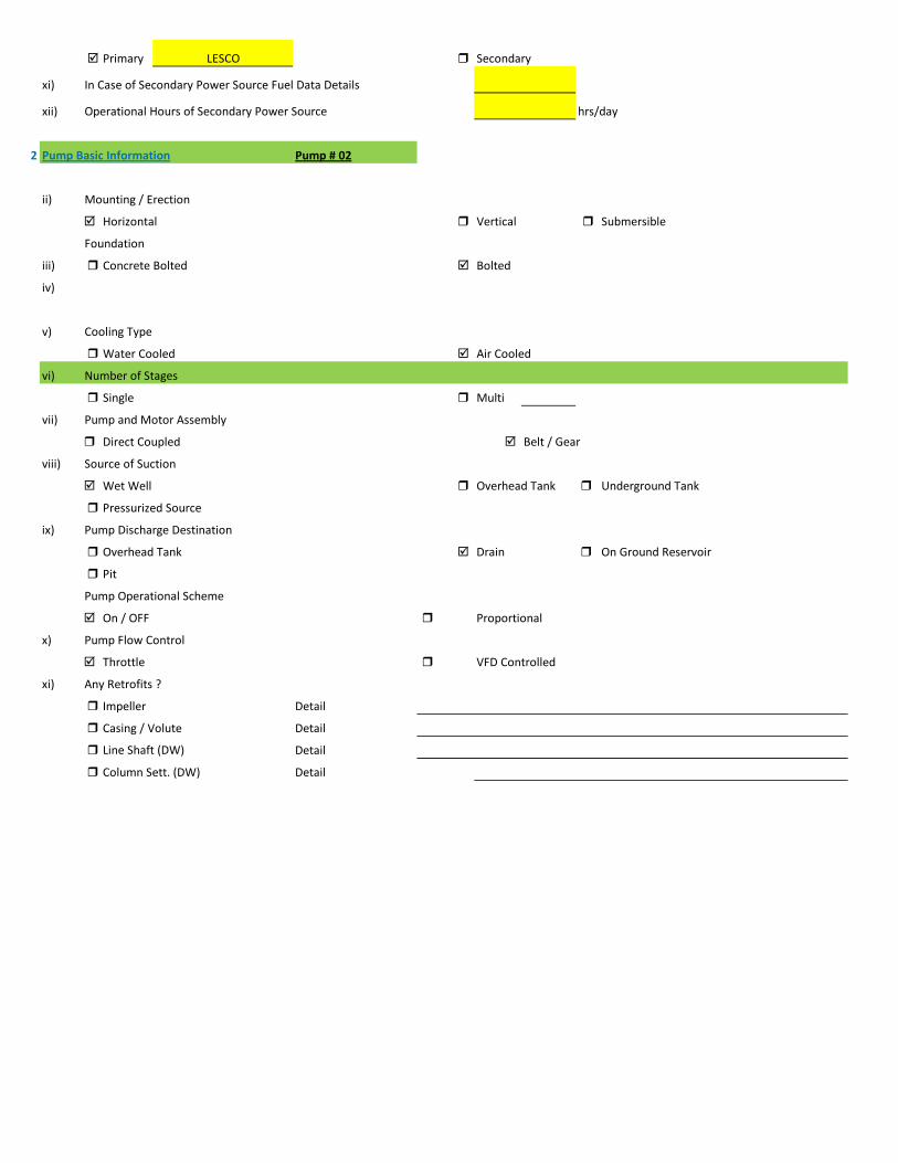
Primary LESCO Secondary
xi) In Case of Secondary Power Source Fuel Data Details
xii) Operational Hours of Secondary Power Source hrs/day
2 Pump Basic Information Pump # 02
ii) Mounting / Erection
Horizontal Vertical Submersible
Foundation
iii) Concrete Bolted Bolted
iv)
v) Cooling Type
Water Cooled Air Cooled
vi) Number of Stages
Single Multi
vii) Pump and Motor Assembly
Direct Coupled Belt / Gear
viii) Source of Suction
Wet Well Overhead Tank Underground Tank
Pressurized Source
ix) Pump Discharge Destination
Overhead Tank Drain On Ground Reservoir
Pit
Pump Operational Scheme
On / OFF Proportional
x) Pump Flow Control
Throttle VFD Controlled
xi) Any Retrofits ?
Impeller Detail
Casing / Volute Detail
Line Shaft (DW) Detail
Column Sett. (DW) Detail

Motor Replacement Detail
Motor Rewinding Detail
xii) Self Priming
Yes No NA (not applicable)
xiii) Non Clogging (In case of wastewater)
Yes No
xiv) Flowmeter Available
Yes No
xv) Flowmeter Working
Working Properly Malfunctioning (Damaged)
3 Pump Nameplate Data
i) Make / Brand KSB Country Pakistan
ii) Model Serial
iii) Certification Mark
iv) Year of Manufacture
v) Flowrate (Q) 2 Cusec 204 m3/hr
vi) Head (H) ft
vii) Discharge Pressure (P) Psig
viii) Power / HP / BHP BHP
ix) Speed (n) RPM
x) Maximum Pressure (Pmax)
xi) Maxiumum Allowable Temperature
5 Piping System
Suction Side
Select Pipe Material of Construction MS Pipe
i) Enter Diameter of Suction Pipe (In) 6
ii) Enter Length of Suction Pipe (ft) 17
iii) Enter Fittings on Suction Pipe
Fitting Type 1 Qty Type 2 Qty Type 3 Qty
Valves Flow control 1
Bends
Strainer 1
viii) Availbility of Pressure Gauge Yes No
ix) Suction Pressure

Discharge Side
Pipe Material of Construction MS Pipe
i) Diameter of Discharge Pipe (in) 6
ii) Length of Discharge Pipe (ft) 20 Estimated
iii) Fittings on Discharge Pipe
Fitting Type 1 Qty Type 2 Qty Type 3 Qty
Valves Non return 1 1
Bends 1
Strainer
vi) Discharge Elevation (from Datum Line) 25 ft
Suction Side Elevation 12 ft
vii) Availbility of Pressure Gauge Yes No
viii) Discharge Pressure psig
6 Motor Nameplate Data
i) Manufacturer Siemens
ii) Rated kW / hp 20 hp 15 kW
iii) Voltage Range Volts
iv) Current Amperes
v) Power Factor (Cos ɸ)
Standard
Ambient Temp oC
Year of Manufacturing
Efficiency Class
IE3 Eff 1
IE2 Eff 2
IE1 Eff 3
Standard Efficiency
vi) Motor Speed RPM
vii) Reference Frequency 50 Hz
viii) Insulation Class
ix) Motor Frame Size
x)
7 Electrical System Observations
i) Electrical Meter Reference Number
ii) Meter Reading
iii) Meter Time and Date
Correct FALSE

Lag by Lead by
iv) Transformer Rating (kVA) 50 Condition OK
Pump O & M Cost
v) Motor Starting Method
Direct Online Star (Wye) - Delta
Autotransformer Starter Soft Starter
Variable Frequency Drives
v) Electrical Protections Available
Earthing / Grounding Fuses or Miniature Circuit Breaker (MCB)
Earth Leakage Circuit Breaker (ELCB) and Residual Current Circuit Breaker (RCCB)
PFI Plant Not Installed
Panel Condition/Issues Average
Gland Leakage
Non Return Valve
Flow Meter not available
Pressure Gauge not available
Wiring fair
Housekeeping
Motor Terminal ok
Foundation/Civil work
Field Measurements
8 Flow Measurement
i) Flow Measurement Location
Discharge Pipe Suction Pipe
ii) Pipe Material of Construction MS Pipe
iii) Paint on Pipe Yes No
iv) Pipe Diameter 6 inches
v) Pipe Perimeter 479 mm
vi) Type of Clamping (V/N/Z) V
viii) Flow Measurement 180 m3/hr 3 m3/min
Velocity in Pipe 2.74 m/sec
Pressure
i) Pressure at Discharge Side of Pump psig
ii) Pressure at Suction Side of Pump
ii) Total Length (Suction+Discahrge Pipe) 11 meter
Electric Measurements Volt 383.5 388 387
Ampere 20 17.2 17.9
kW 8.7 Power Factor 0.71
vi) Motor Working on Loading Basis 58 %
Oversize Undersize Properly Sized
Speed
i) Speed of Motor 0 RPM
ii) Speed of Pump Impeller RPM

Noise Level
Noise Level (db(A)) Avg. Max:
Thermal Imaging
i) Motor Motor Pump Coupling
Pump Volute Casing Pump Bearings
Electric Panels
10 Calculations
ii) Static Suction Head (Only for WW Pump) 12 ft
v) Static Discahrge Head 25 ft
vi) Frictional Head (Suction and Discahrge) 18.97 ft
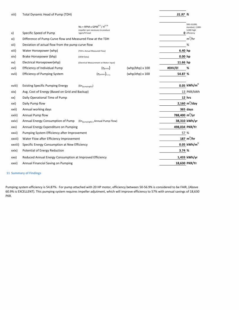
viii) Total Dynamic Head of Pump (TDH) 31.97 ft
x) Specific Speed of Pump
Ns = RPM x GPM0.5 / H0.75
impeller rpm necessary to produce 1gpm/ft head 0
500-10,000, standard, 2,000-3,000 high efficiency
xi) Difference of Pump Curve flow and Measured Flow at the TDH m3/hr
xii) Deviation of actual flow from the pump curve flow %
xiii) Water Horsepower (whp) (TDH x Actual Measured Flow) 6.40 hp
xiv) Brake Horsepower (bhp) (OEM Data) 0.00 hp
xv) Electrical Horsepower(ehp) (Electrical Measurement at Motor input) 11.66 hp
xvi) Efficiency of Individual Pump (ηpump) (whp/bhp) x 100 #DIV/0! %
xvii) Efficiency of Pumping System (ηsystem)Existing (whp/ehp) x 100 54.87 %
xviii) Existing Specific Pumping Energy (En(pumping01)) 0.05 kWh/m3
xix) Avg. Cost of Energy (Based on Grid and Backup) 13 PKR/kWh
xx) Daily Operational Time of Pump 12 hrs
xxi) Daily Pump flow 2,160 m3/day
xxii) Annual working days 365 days
xxiii) Annual Pump flow 788,400 m3/yr
xxiv) Annual Energy Consumption of Pump (En(pumping01) x Annual Pump Flow) 38,310 kWh/yr
xxv) Annual Energy Expenditure on Pumping 498,034 PKR/Yr
xxvi) Pumping System Efficiency after Improvement 57 %
xxvii) Water Flow after Efficiency Improvement 187 m3/hr
xxviii) Specific Energy Consumption at New Efficiency 0.05 kWh/m3
xxix) Potential of Energy Reduction 3.74 %
xxx) Reduced Annual Energy Consumption at Improved Efficiency 1,433 kWh/yr
xxxi) Annual Financial Saving on Pumping 18,630 PKR/Yr
11 Summary of Findings
Pumping system efficiency is 54.87%. For pump attached with 20 HP motor, efficiency between 50-56.9% is considered to be FAIR, (Above 60.9% is EXCELLENT). This pumping system requires impeller adjutment, which will improve efficiency to 57% with annual savings of 18,630 PKR.

Issues & Recommendations
12 ISSUES RECOMMENDATIONS
i)
ii)
iii)
iv)
v)
vi)
vii)
viii)
ix)
x)
xi)
xii)
xiii)
xiv)
xv)
xvi)
xvii)
xviii)
Financial Analysis / Indicators
12 Estimated Investment for Improvement Plan 86,000 PKR
PFI plant is not installed PFI of 12.5 KVAr is recommended for disposal station
Voltmeter is not working
Install AmmeterAmmeter is not working
water flow meter is not Available Install new water flow meter
Install Voltmeter
There is no pressure gauge installed at discahrge pipeline Install digital pressure gauge at discahrge pipeline

1 Pumping Station Information
1 Fresh Water Supply
2 Wastewater Disposal
3 Waste Water Treatment Plant
4 Water Treatment Plant
Name of Engineer
WASA Staff Name
i) Name of Pumping Station Achant Garh-I Disposal Station
ii) Name of Subdivision Mughalpura , Lahore
iii) Operator Name & Contact Rizwan
iv) Total Number of Pumps Installed 4
v) Total Number of Pumps in Operation 2
vi) Year of Starting Operation
vii) Types of Pumps
Standard Deep Well Water Turbine Pumps Qty
Submersible Deep Well Water Turbine Pumps Qty
Centrifugal Pump Qty 2
Submersible Disposal Pump Qty 2
vi) Operational Scheme of Pumps Qty
Independent 4
Series
Parallel
vii) Any Header / Tank / Reservoir
Yes No
viii) Any Record Keeping
Time Flow Pressure
Level Quality of Water Power Consumption
Maintenance Record Electricity Bill Fuel Consumption Data
viii) Daily Operational Time 12 hrs/day Estimated
ix) Annual Working Days 365 days
x) Source of Power
Energy Report of WASA Pumps

Primary LESCO Secondary
xi) In Case of Secondary Power Source Fuel Data Details
xii) Operational Hours of Secondary Power Source hrs/day
2 Pump Basic Information Pump # 03
ii) Mounting / Erection
Horizontal Vertical Submersible
Foundation
iii) Concrete Bolted Bolted
iv)
v) Cooling Type
Water Cooled Air Cooled
vi) Number of Stages
Single Multi
vii) Pump and Motor Assembly
Direct Coupled Belt / Gear
viii) Source of Suction
Wet Well Overhead Tank Underground Tank
Pressurized Source
ix) Pump Discharge Destination
Overhead Tank Drain On Ground Reservoir
Pit
Pump Operational Scheme
On / OFF Proportional
x) Pump Flow Control
Throttle VFD Controlled
xi) Any Retrofits ?
Impeller Detail
Casing / Volute Detail
Line Shaft (DW) Detail
Column Sett. (DW) Detail

Motor Replacement Detail
Motor Rewinding Detail
xii) Self Priming
Yes No NA (not applicable)
xiii) Non Clogging (In case of wastewater)
Yes No
xiv) Flowmeter Available
Yes No
xv) Flowmeter Working
Working Properly Malfunctioning (Damaged)
3 Pump Nameplate Data
i) Make / Brand KSB Country Pakistan
ii) Model Serial
iii) Certification Mark
iv) Year of Manufacture
v) Flowrate (Q) 2 Cusec 204 m3/hr
vi) Head (H) ft
vii) Discharge Pressure (P) Psig
viii) Power / HP / BHP BHP
ix) Speed (n) RPM
x) Maximum Pressure (Pmax)
xi) Maxiumum Allowable Temperature
5 Piping System
Suction Side
Select Pipe Material of Construction MS Pipe
i) Enter Diameter of Suction Pipe (In) 6
ii) Enter Length of Suction Pipe (ft) 2
iii) Enter Fittings on Suction Pipe
Fitting Type 1 Qty Type 2 Qty Type 3 Qty
Valves Flow control 1
Bends
Strainer 1
viii) Availbility of Pressure Gauge Yes No
ix) Suction Pressure
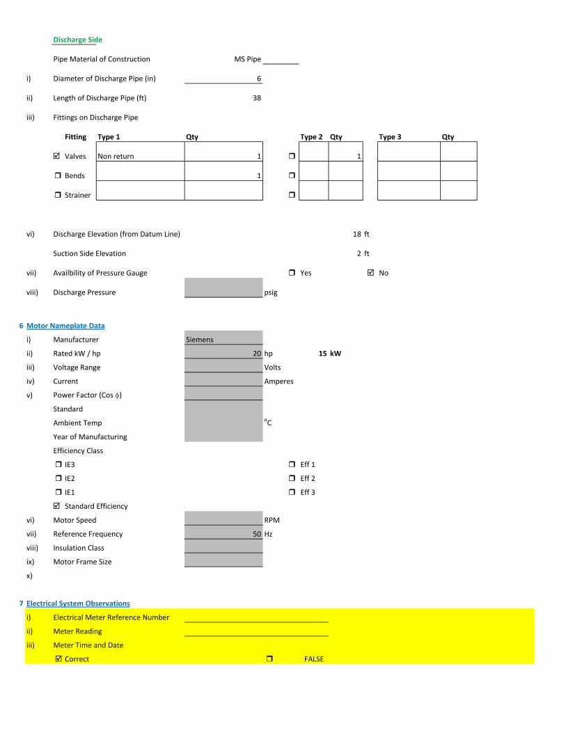
Discharge Side
Pipe Material of Construction MS Pipe
i) Diameter of Discharge Pipe (in) 6
ii) Length of Discharge Pipe (ft) 38
iii) Fittings on Discharge Pipe
Fitting Type 1 Qty Type 2 Qty Type 3 Qty
Valves Non return 1 1
Bends 1
Strainer
vi) Discharge Elevation (from Datum Line) 18 ft
Suction Side Elevation 2 ft
vii) Availbility of Pressure Gauge Yes No
viii) Discharge Pressure psig
6 Motor Nameplate Data
i) Manufacturer Siemens
ii) Rated kW / hp 20 hp 15 kW
iii) Voltage Range Volts
iv) Current Amperes
v) Power Factor (Cos ɸ)
Standard
Ambient Temp oC
Year of Manufacturing
Efficiency Class
IE3 Eff 1
IE2 Eff 2
IE1 Eff 3
Standard Efficiency
vi) Motor Speed RPM
vii) Reference Frequency 50 Hz
viii) Insulation Class
ix) Motor Frame Size
x)
7 Electrical System Observations
i) Electrical Meter Reference Number
ii) Meter Reading
iii) Meter Time and Date
Correct FALSE

Lag by Lead by
iv) Transformer Rating (kVA) 100 Condition OK
Pump O & M Cost
v) Motor Starting Method
Direct Online Star (Wye) - Delta
Autotransformer Starter Soft Starter
Variable Frequency Drives
v) Electrical Protections Available
Earthing / Grounding Fuses or Miniature Circuit Breaker (MCB)
Earth Leakage Circuit Breaker (ELCB) and Residual Current Circuit Breaker (RCCB)
PFI Plant Not Installed
Panel Condition/Issues OK
Gland Leakage
Non Return Valve
Flow Meter not available
Pressure Gauge not available
Wiring fair
Housekeeping
Motor Terminal ok
Foundation/Civil work
Field Measurements
8 Flow Measurement
i) Flow Measurement Location
Discharge Pipe Suction Pipe
ii) Pipe Material of Construction MS Pipe
iii) Paint on Pipe Yes No
iv) Pipe Diameter 6 inches
v) Pipe Perimeter 479 mm
vi) Type of Clamping (V/N/Z) V
viii) Flow Measurement 180 m3/hr 3 m3/min
Velocity in Pipe 2.74 m/sec
Pressure
i) Pressure at Discharge Side of Pump psig
ii) Pressure at Suction Side of Pump
ii) Total Length (Suction+Discahrge Pipe) 12 meter
Electric Measurements Volt 418 419 416.8
Ampere 20.4 20.8 22.6
kW 11.7 Power Factor 0.76
vi) Motor Working on Loading Basis 78 %
Oversize Undersize Properly Sized
Speed
i) Speed of Motor 0 RPM
ii) Speed of Pump Impeller RPM

Noise Level
Noise Level (db(A)) Avg. Max:
Thermal Imaging
i) Motor Motor Pump Coupling
Pump Volute Casing Pump Bearings
Electric Panels
10 Calculations
ii) Static Suction Head (Only for WW Pump) 2 ft
v) Static Discahrge Head 18 ft
vi) Frictional Head (Suction and Discahrge) 19.08 ft

viii) Total Dynamic Head of Pump (TDH) 35.08 ft
x) Specific Speed of Pump
Ns = RPM x GPM0.5 / H0.75
impeller rpm necessary to produce 1gpm/ft head 0
500-10,000, standard, 2,000-3,000 high efficiency
xi) Difference of Pump Curve flow and Measured Flow at the TDH m3/hr
xii) Deviation of actual flow from the pump curve flow %
xiii) Water Horsepower (whp) (TDH x Actual Measured Flow) 7.02 hp
xiv) Brake Horsepower (bhp) (OEM Data) 0.00 hp
xv) Electrical Horsepower(ehp) (Electrical Measurement at Motor input) 15.68 hp
xvi) Efficiency of Individual Pump (ηpump) (whp/bhp) x 100 #DIV/0! %
xvii) Efficiency of Pumping System (ηsystem)Existing (whp/ehp) x 100 44.77 %
xviii) Existing Specific Pumping Energy (En(pumping01)) 0.07 kWh/m3
xix) Avg. Cost of Energy (Based on Grid and Backup) 13 PKR/kWh
xx) Daily Operational Time of Pump 12 hrs
xxi) Daily Pump flow 2,160 m3/day
xxii) Annual working days 365 days
xxiii) Annual Pump flow 788,400 m3/yr
xxiv) Annual Energy Consumption of Pump (En(pumping01) x Annual Pump Flow) 51,521 kWh/yr
xxv) Annual Energy Expenditure on Pumping 669,770 PKR/Yr
xxvi) Pumping System Efficiency after Improvement 57 %
xxvii) Water Flow after Efficiency Improvement 229 m3/hr
xxviii) Specific Energy Consumption at New Efficiency 0.05 kWh/m3
xxix) Potential of Energy Reduction 21.45 %
xxx) Reduced Annual Energy Consumption at Improved Efficiency 11,053 kWh/yr
xxxi) Annual Financial Saving on Pumping 143,695 PKR/Yr
11 Summary of Findings
Pumping system efficiency is 44.47%. For pump attached with 20 HP motor, efficiency <48% is considered to be LOW, (Above 60.9% is EXCELLENT). This pumping system requires impeller adjustment and repair and maintenance. After this intervention its efficiency will be improved to 57% (GOOD Efficiency range), with annual savings of 143,695 PKR,
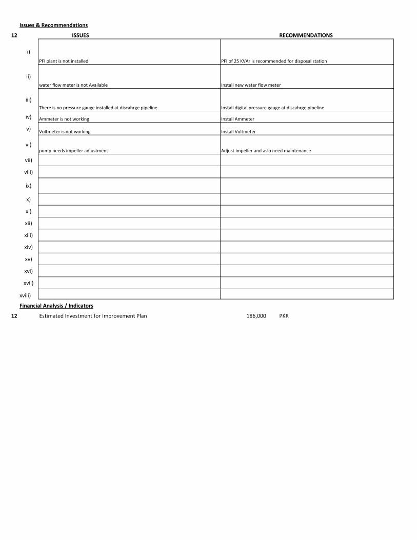
Issues & Recommendations
12 ISSUES RECOMMENDATIONS
i)
ii)
iii)
iv)
v)
vi)
vii)
viii)
ix)
x)
xi)
xii)
xiii)
xiv)
xv)
xvi)
xvii)
xviii)
Financial Analysis / Indicators
12 Estimated Investment for Improvement Plan 186,000 PKR
pump needs impeller adjustment Adjust impeller and aslo need maintenance
PFI plant is not installed PFI of 25 KVAr is recommended for disposal station
Voltmeter is not working
Install AmmeterAmmeter is not working
water flow meter is not Available Install new water flow meter
Install Voltmeter
There is no pressure gauge installed at discahrge pipeline Install digital pressure gauge at discahrge pipeline

1 Pumping Station Information
1 Fresh Water Supply
2 Wastewater Disposal
3 Waste Water Treatment Plant
4 Water Treatment Plant
Name of Engineer
WASA Staff Name
i) Name of Pumping Station Achant Garh-I Disposal Station
ii) Name of Subdivision Mughalpura , Lahore
iii) Operator Name & Contact Rizwan
iv) Total Number of Pumps Installed 4
v) Total Number of Pumps in Operation 2
vi) Year of Starting Operation
vii) Types of Pumps
Standard Deep Well Water Turbine Pumps Qty
Submersible Deep Well Water Turbine Pumps Qty
Centrifugal Pump Qty 2
Submersible Disposal Pump Qty 2
vi) Operational Scheme of Pumps Qty
Independent 4
Series
Parallel
vii) Any Header / Tank / Reservoir
Yes No
viii) Any Record Keeping
Time Flow Pressure
Level Quality of Water Power Consumption
Maintenance Record Electricity Bill Fuel Consumption Data
viii) Daily Operational Time 12 hrs/day Estimated
ix) Annual Working Days 365 days
x) Source of Power
Energy Report of WASA Pumps

Primary LESCO Secondary
xi) In Case of Secondary Power Source Fuel Data Details
xii) Operational Hours of Secondary Power Source hrs/day
2 Pump Basic Information Pump # 04
ii) Mounting / Erection
Horizontal Vertical Submersible
Foundation
iii) Concrete Bolted Bolted
iv)
v) Cooling Type
Water Cooled Air Cooled
vi) Number of Stages
Single Multi
vii) Pump and Motor Assembly
Direct Coupled Belt / Gear
viii) Source of Suction
Wet Well Overhead Tank Underground Tank
Pressurized Source
ix) Pump Discharge Destination
Overhead Tank Drain On Ground Reservoir
Pit
Pump Operational Scheme
On / OFF Proportional
x) Pump Flow Control
Throttle VFD Controlled
xi) Any Retrofits ?
Impeller Detail
Casing / Volute Detail
Line Shaft (DW) Detail
Column Sett. (DW) Detail

Motor Replacement Detail
Motor Rewinding Detail
xii) Self Priming
Yes No NA (not applicable)
xiii) Non Clogging (In case of wastewater)
Yes No
xiv) Flowmeter Available
Yes No
xv) Flowmeter Working
Working Properly Malfunctioning (Damaged)
3 Pump Nameplate Data
i) Make / Brand KSB Country Pakistan
ii) Model Serial
iii) Certification Mark
iv) Year of Manufacture
v) Flowrate (Q) 4 Cusec 408 m3/hr
vi) Head (H) ft
vii) Discharge Pressure (P) Psig
viii) Power / HP / BHP BHP
ix) Speed (n) RPM
x) Maximum Pressure (Pmax)
xi) Maxiumum Allowable Temperature
5 Piping System
Suction Side
Select Pipe Material of Construction MS Pipe
i) Enter Diameter of Suction Pipe (In) 8
ii) Enter Length of Suction Pipe (ft) 2
iii) Enter Fittings on Suction Pipe
Fitting Type 1 Qty Type 2 Qty Type 3 Qty
Valves Flow control 1
Bends
Strainer 1
viii) Availbility of Pressure Gauge Yes No
ix) Suction Pressure

Discharge Side
Pipe Material of Construction MS Pipe
i) Diameter of Discharge Pipe (in) 8
ii) Length of Discharge Pipe (ft) 38
iii) Fittings on Discharge Pipe
Fitting Type 1 Qty Type 2 Qty Type 3 Qty
Valves Non return 1 1
Bends 1
Strainer
vi) Discharge Elevation (from Datum Line) 22 ft
Suction Side Elevation 2 ft
vii) Availbility of Pressure Gauge Yes No
viii) Discharge Pressure psig
6 Motor Nameplate Data
i) Manufacturer Siemens
ii) Rated kW / hp 40 hp 30 kW
iii) Voltage Range Volts
iv) Current Amperes
v) Power Factor (Cos ɸ)
Standard
Ambient Temp oC
Year of Manufacturing
Efficiency Class
IE3 Eff 1
IE2 Eff 2
IE1 Eff 3
Standard Efficiency
vi) Motor Speed RPM
vii) Reference Frequency 50 Hz
viii) Insulation Class
ix) Motor Frame Size
x)
7 Electrical System Observations
i) Electrical Meter Reference Number
ii) Meter Reading
iii) Meter Time and Date
Correct FALSE

Lag by Lead by
iv) Transformer Rating (kVA) 100 Condition OK
Pump O & M Cost
v) Motor Starting Method
Direct Online Star (Wye) - Delta
Autotransformer Starter Soft Starter
Variable Frequency Drives
v) Electrical Protections Available
Earthing / Grounding Fuses or Miniature Circuit Breaker (MCB)
Earth Leakage Circuit Breaker (ELCB) and Residual Current Circuit Breaker (RCCB)
PFI Plant Not Installed
Panel Condition/Issues OK
Gland Leakage
Non Return Valve
Flow Meter not available
Pressure Gauge not available
Wiring fair
Housekeeping
Motor Terminal ok
Foundation/Civil work
Field Measurements
8 Flow Measurement
i) Flow Measurement Location
Discharge Pipe Suction Pipe
ii) Pipe Material of Construction MS Pipe
iii) Paint on Pipe Yes No
iv) Pipe Diameter 8 inches
v) Pipe Perimeter 638 mm
vi) Type of Clamping (V/N/Z) V
viii) Flow Measurement 315 m3/hr 5.25 m3/min
Velocity in Pipe 2.70 m/sec
Pressure
i) Pressure at Discharge Side of Pump psig
ii) Pressure at Suction Side of Pump
ii) Total Length (Suction+Discahrge Pipe) 12 meter
Electric Measurements Volt 420.5 418.7 422.2
Ampere 25 27.5 24.1
kW 13.9 Power Factor 0.75
vi) Motor Working on Loading Basis 47 %
Oversize Undersize Properly Sized
Speed
i) Speed of Motor 0 RPM
ii) Speed of Pump Impeller RPM

Noise Level
Noise Level (db(A)) Avg. Max:
Thermal Imaging
i) Motor Motor Pump Coupling
Pump Volute Casing Pump Bearings
Electric Panels
10 Calculations
ii) Static Suction Head (Only for WW Pump) 2 ft
v) Static Discahrge Head 22 ft
vi) Frictional Head (Suction and Discahrge) 18.08 ft
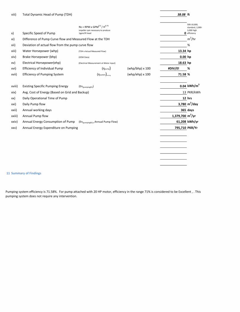
viii) Total Dynamic Head of Pump (TDH) 38.08 ft
x) Specific Speed of Pump
Ns = RPM x GPM0.5 / H0.75
impeller rpm necessary to produce 1gpm/ft head 0
500-10,000, standard, 2,000-3,000 high efficiency
xi) Difference of Pump Curve flow and Measured Flow at the TDH m3/hr
xii) Deviation of actual flow from the pump curve flow %
xiii) Water Horsepower (whp) (TDH x Actual Measured Flow) 13.34 hp
xiv) Brake Horsepower (bhp) (OEM Data) 0.00 hp
xv) Electrical Horsepower(ehp) (Electrical Measurement at Motor input) 18.63 hp
xvi) Efficiency of Individual Pump (ηpump) (whp/bhp) x 100 #DIV/0! %
xvii) Efficiency of Pumping System (ηsystem)Existing (whp/ehp) x 100 71.58 %
xviii) Existing Specific Pumping Energy (En(pumping01)) 0.04 kWh/m3
xix) Avg. Cost of Energy (Based on Grid and Backup) 13 PKR/kWh
xx) Daily Operational Time of Pump 12 hrs
xxi) Daily Pump flow 3,780 m3/day
xxii) Annual working days 365 days
xxiii) Annual Pump flow 1,379,700 m3/yr
xxiv) Annual Energy Consumption of Pump (En(pumping01) x Annual Pump Flow) 61,208 kWh/yr
xxv) Annual Energy Expenditure on Pumping 795,710 PKR/Yr
11 Summary of Findings
Pumping system efficiency is 71.58%. For pump attached with 20 HP motor, efficiency in the range 71% is considered to be Excellent , . This pumping system does not require any intervention.
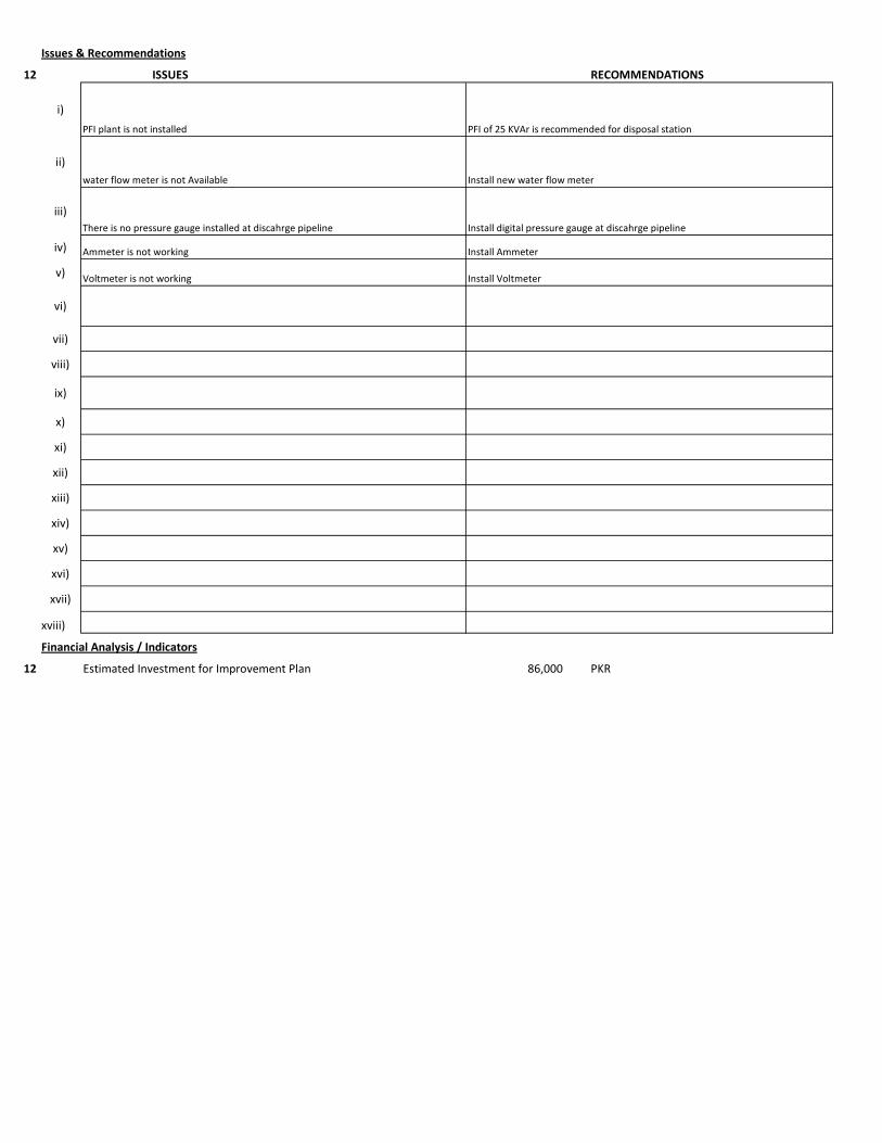
Issues & Recommendations
12 ISSUES RECOMMENDATIONS
i)
ii)
iii)
iv)
v)
vi)
vii)
viii)
ix)
x)
xi)
xii)
xiii)
xiv)
xv)
xvi)
xvii)
xviii)
Financial Analysis / Indicators
12 Estimated Investment for Improvement Plan 86,000 PKR
PFI plant is not installed PFI of 25 KVAr is recommended for disposal station
Voltmeter is not working
Install AmmeterAmmeter is not working
water flow meter is not Available Install new water flow meter
Install Voltmeter
There is no pressure gauge installed at discahrge pipeline Install digital pressure gauge at discahrge pipeline
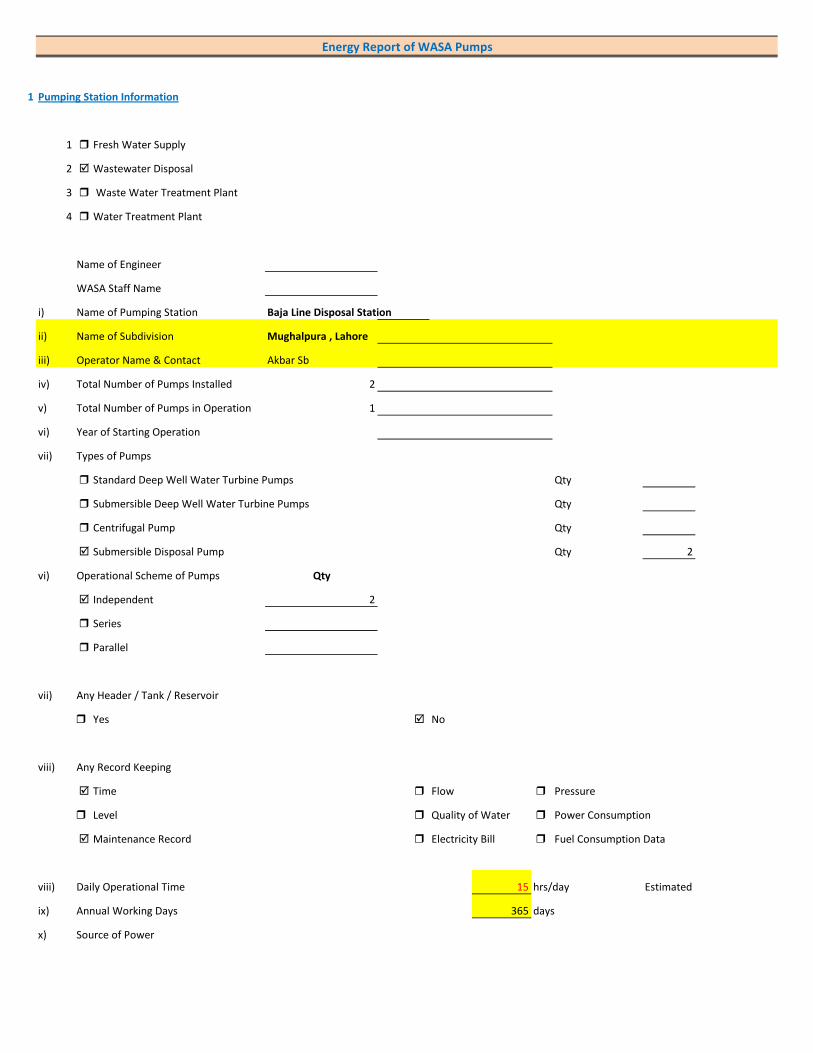
1 Pumping Station Information
1 Fresh Water Supply
2 Wastewater Disposal
3 Waste Water Treatment Plant
4 Water Treatment Plant
Name of Engineer
WASA Staff Name
i) Name of Pumping Station Baja Line Disposal Station
ii) Name of Subdivision Mughalpura , Lahore
iii) Operator Name & Contact Akbar Sb
iv) Total Number of Pumps Installed 2
v) Total Number of Pumps in Operation 1
vi) Year of Starting Operation
vii) Types of Pumps
Standard Deep Well Water Turbine Pumps Qty
Submersible Deep Well Water Turbine Pumps Qty
Centrifugal Pump Qty
Submersible Disposal Pump Qty 2
vi) Operational Scheme of Pumps Qty
Independent 2
Series
Parallel
vii) Any Header / Tank / Reservoir
Yes No
viii) Any Record Keeping
Time Flow Pressure
Level Quality of Water Power Consumption
Maintenance Record Electricity Bill Fuel Consumption Data
viii) Daily Operational Time 15 hrs/day Estimated
ix) Annual Working Days 365 days
x) Source of Power
Energy Report of WASA Pumps
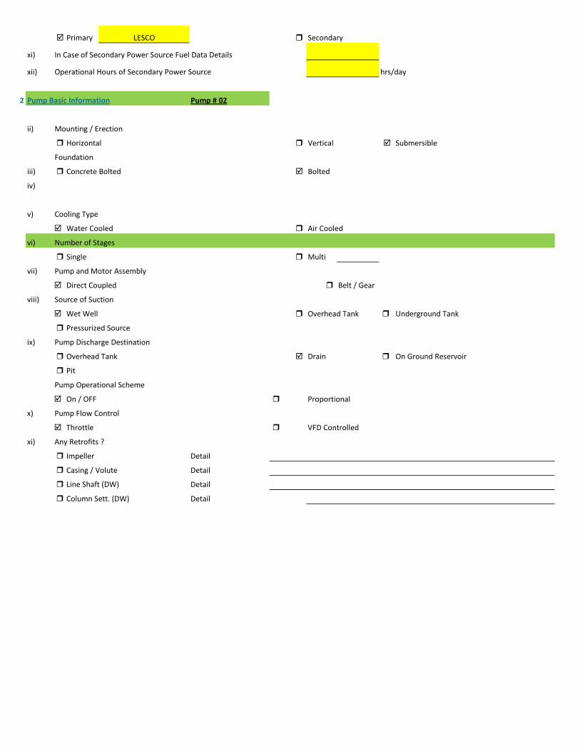
Primary LESCO Secondary
xi) In Case of Secondary Power Source Fuel Data Details
xii) Operational Hours of Secondary Power Source hrs/day
2 Pump Basic Information Pump # 02
ii) Mounting / Erection
Horizontal Vertical Submersible
Foundation
iii) Concrete Bolted Bolted
iv)
v) Cooling Type
Water Cooled Air Cooled
vi) Number of Stages
Single Multi
vii) Pump and Motor Assembly
Direct Coupled Belt / Gear
viii) Source of Suction
Wet Well Overhead Tank Underground Tank
Pressurized Source
ix) Pump Discharge Destination
Overhead Tank Drain On Ground Reservoir
Pit
Pump Operational Scheme
On / OFF Proportional
x) Pump Flow Control
Throttle VFD Controlled
xi) Any Retrofits ?
Impeller Detail
Casing / Volute Detail
Line Shaft (DW) Detail
Column Sett. (DW) Detail
Motor Replacement Detail
Motor Rewinding Detail
xii) Self Priming
Yes No NA (not applicable)
xiii) Non Clogging (In case of wastewater)
Yes No
xiv) Flowmeter Available
Yes No
xv) Flowmeter Working
Working Properly Malfunctioning (Damaged)
3 Pump Nameplate Data
i) Make / Brand KSB Country Pakistan
ii) Model Serial
iii) Certification Mark
iv) Year of Manufacture
v) Flowrate (Q) 2 Cusec 204 m3/hr
vi) Head (H) ft
vii) Discharge Pressure (P) Psig
viii) Power / HP / BHP BHP
ix) Speed (n) RPM
x) Maximum Pressure (Pmax)
xi) Maxiumum Allowable Temperature
5 Piping System
Suction Side
Select Pipe Material of Construction MS Pipe
i) Enter Diameter of Suction Pipe (In) 6
ii) Enter Length of Suction Pipe (ft) 2
iii) Enter Fittings on Suction Pipe
Fitting Type 1 Qty Type 2 Qty Type 3 Qty
Valves Flow control 1
Bends
Strainer 1
viii) Availbility of Pressure Gauge Yes No
ix) Suction Pressure
Discharge Side
Pipe Material of Construction MS Pipe
i) Diameter of Discharge Pipe (in) 6
ii) Length of Discharge Pipe (ft) 38 Estimated
iii) Fittings on Discharge Pipe
Fitting Type 1 Qty Type 2 Qty Type 3 Qty
Valves Non return 1 1
Bends 1
Strainer
vi) Discharge Elevation (from Datum Line) 20 ft
Suction Side Elevation 2 ft
vii) Availbility of Pressure Gauge Yes No
viii) Discharge Pressure psig
6 Motor Nameplate Data
i) Manufacturer Siemens
ii) Rated kW / hp 20 hp 15 kW
iii) Voltage Range Volts
iv) Current Amperes
v) Power Factor (Cos ɸ)
Standard
Ambient Temp oC
Year of Manufacturing
Efficiency Class
IE3 Eff 1
IE2 Eff 2
IE1 Eff 3
Standard Efficiency
vi) Motor Speed RPM
vii) Reference Frequency 50 Hz
viii) Insulation Class
ix) Motor Frame Size
x)
7 Electrical System Observations
i) Electrical Meter Reference Number
ii) Meter Reading
iii) Meter Time and Date
Correct FALSE

Lag by Lead by
iv) Transformer Rating (kVA) 50 Condition OK
Pump O & M Cost
v) Motor Starting Method
Direct Online Star (Wye) - Delta
Autotransformer Starter Soft Starter
Variable Frequency Drives
v) Electrical Protections Available
Earthing / Grounding Fuses or Miniature Circuit Breaker (MCB)
Earth Leakage Circuit Breaker (ELCB) and Residual Current Circuit Breaker (RCCB)
PFI Plant Not Installed
Panel Condition/Issues OK
Gland Leakage
Non Return Valve
Flow Meter not available
Pressure Gauge not available
Wiring fair
Housekeeping
Motor Terminal ok
Foundation/Civil work
Field Measurements
8 Flow Measurement
i) Flow Measurement Location
Discharge Pipe Suction Pipe
ii) Pipe Material of Construction MS Pipe
iii) Paint on Pipe Yes No
iv) Pipe Diameter 6 inches
v) Pipe Perimeter 479 mm
vi) Type of Clamping (V/N/Z) V
viii) Flow Measurement 100 m3/hr 1.6667 m3/min
Velocity in Pipe 1.52 m/sec
Pressure
i) Pressure at Discharge Side of Pump psig
ii) Pressure at Suction Side of Pump
ii) Total Length (Suction+Discahrge Pipe) 12 meter
Electric Measurements Volt 410.7 410.1 399
Ampere 20.9 20.5 20.5
kW 9 Power Factor 0.62
vi) Motor Working on Loading Basis 60 %
Oversize Undersize Properly Sized
Speed
i) Speed of Motor 0 RPM
ii) Speed of Pump Impeller RPM
Noise Level
Noise Level (db(A)) Avg. Max:
Thermal Imaging
i) Motor Motor Pump Coupling
Pump Volute Casing Pump Bearings
Electric Panels
10 Calculations
ii) Static Suction Head (Only for WW Pump) 2 ft
v) Static Discahrge Head 20 ft
vi) Frictional Head (Suction and Discahrge) 5.93 ft

viii) Total Dynamic Head of Pump (TDH) 23.93 ft
x) Specific Speed of Pump
Ns = RPM x GPM0.5 / H0.75
impeller rpm necessary to produce 1gpm/ft head 0
500-10,000, standard, 2,000-3,000 high efficiency
xi) Difference of Pump Curve flow and Measured Flow at the TDH m3/hr
xii) Deviation of actual flow from the pump curve flow %
xiii) Water Horsepower (whp) (TDH x Actual Measured Flow) 2.66 hp
xiv) Brake Horsepower (bhp) (OEM Data) 0.00 hp
xv) Electrical Horsepower(ehp) (Electrical Measurement at Motor input) 12.06 hp
xvi) Efficiency of Individual Pump (ηpump) (whp/bhp) x 100 #DIV/0! %
xvii) Efficiency of Pumping System (ηsystem)Existing (whp/ehp) x 100 22.06 %
xviii) Existing Specific Pumping Energy (En(pumping01)) 0.09 kWh/m3
xix) Avg. Cost of Energy (Based on Grid and Backup) 13 PKR/kWh
xx) Daily Operational Time of Pump 15 hrs
xxi) Daily Pump flow 1,500 m3/day
xxii) Annual working days 365 days
xxiii) Annual Pump flow 547,500 m3/yr
xxiv) Annual Energy Consumption of Pump (En(pumping01) x Annual Pump Flow) 49,539 kWh/yr
xxv) Annual Energy Expenditure on Pumping 644,010 PKR/Yr
xxvi) Pumping System Efficiency after Improvement 61 %
xxvii) Water Flow after Efficiency Improvement 277 m3/hr
xxviii) Specific Energy Consumption at New Efficiency 0.03 kWh/m3
xxix) Potential of Energy Reduction 63.84 %
xxx) Reduced Annual Energy Consumption at Improved Efficiency 31,626 kWh/yr
xxxi) Annual Financial Saving on Pumping 411,142 PKR/Yr
11 Summary of Findings
Pumping system efficiency is 22.06%. For pump attached with 20 HP motor, efficiency below 48% is considered to be LOW, (Above 60.9% is EXCELLENT). This pumping system requires pump to be changed. After this intervention its efficiency will be improved to 61% (GOOD Efficiency range), with annual savings of Rs. 411,142 per year,

Issues & Recommendations
12 ISSUES RECOMMENDATIONS
i)
ii)
iii)
iv)
v)
vi)
vii)
viii)
ix)
x)
xi)
xii)
xiii)
xiv)
xv)
xvi)
xvii)
xviii)
Financial Analysis / Indicators
12 Estimated Investment for Improvement Plan 2,216,000 PKR
Voltmeter is not working
Install AmmeterAmmeter is not working
water flow meter is not Available Install new water flow meter
Install Voltmeter
There is no pressure gauge installed at discahrge pipeline Install digital pressure gauge at discahrge pipeline
PFI plant is not installed PFI of 12.5 KVAr is recommended for disposal station
pumping system efficiency is less than 30% replace pump

ANNEXURE-2
Selected Pictures
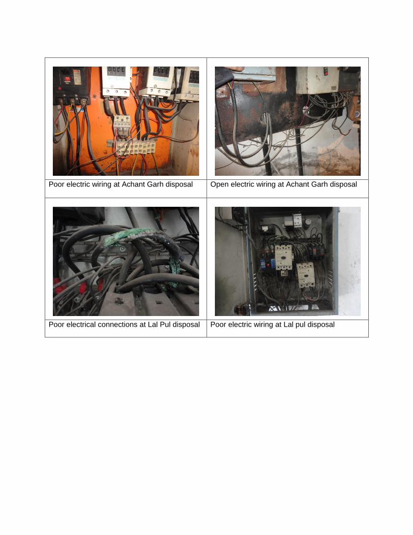
Poor electric wiring at Achant Garh disposal Open electric wiring at Achant Garh disposal
Poor electrical connections at Lal Pul disposal Poor electric wiring at Lal pul disposal
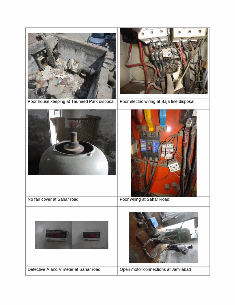
Poor house keeping at Tauheed Park disposal Poor electric wiring at Baja line disposal
No fan cover at Sahar road
Poor wiring at Sahar Road
Defective A and V meter at Sahar road Open motor connections at Jamilabad
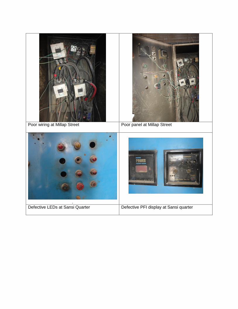
Poor wiring at Millap Street Poor panel at Millap Street
.
Defective LEDs at Sansi Quarter Defective PFI display at Sansi quarter
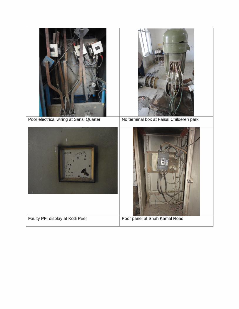
Poor electrical wiring at Sansi Quarter
No terminal box at Faisal Childeren park
Faulty PFI display at Kotli Peer
Poor panel at Shah Kamal Road
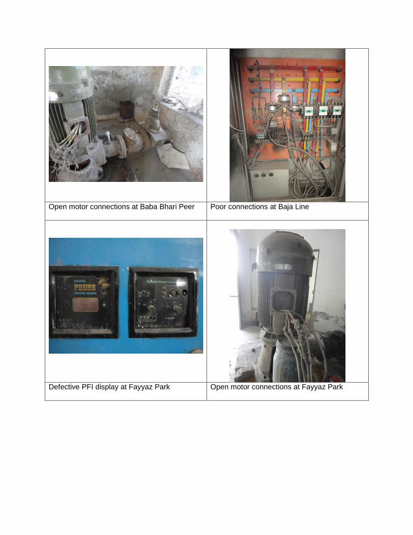
Open motor connections at Baba Bhari Peer
Poor connections at Baja Line
Defective PFI display at Fayyaz Park Open motor connections at Fayyaz Park