Embed Size (px)
Citation preview

ENERGY CONSERVATIONWHY ?
WHAT IS THE NEED?WHO WILL GAIN ?

All India Power Shortages$Existing Supply : 368,046 M Units$Existing Demand : 414,000 M Unit$ Shortage : 11.5 %

POWER COST FOR LAST TEN YEARS
3 – Fold Increase in Last Nine Years
3.153.47
3.75
4.16 4.2 4.21 4.22 4.254.5
0
0.5
1
1.5
2
2.5
3
3.5
4
4.5
1997 1999 2001 2003 2005
UNIT PRICE(Rs/Kwh)

NATIONAL POWER SCENE
$Precarious$Adverse Impact On Industry
$New Project Additions very slow$Action Plan Required for Improvement

COMPARISION OF POWER COST
Comparative Power Cost In Different Countries
4.5
2
1.251
1.7
0
0.5
1
1.5
2
2.5
3
3.5
4
4.5
India USA China SaudiArabia
Europe
UNIT PRICE(Rs/Kwh)

ENERGY SAVING POTENTIAL IN INDIAN INDUSTRY
$Energy Saving Potential Rs.100,000.00 Million/yr
$Equivalent 2500 MW
$Investment Opportunity Rs.200,000.00 Million
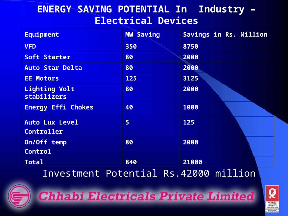
Equipment MW Saving Savings in Rs. Million
VFD 350 8750
Soft Starter 80 2000
Auto Star Delta 80 2000
EE Motors 125 3125
Lighting Volt stabilizers 80 2000
Energy Effi Chokes 40 1000
Auto Lux Level
Controller
5 125
On/Off temp
Control
80 2000
Total 840 21000
ENERGY SAVING POTENTIAL In Industry – Electrical Devices
Investment Potential Rs.42000 million

ENERGY COST AS % OFMANUFACTURING COST
$Chlor Alkali Industry 65%$Cement Industry 40%$Paper Industry 25%$Chemical Industry 15%$Foundry 25%$Engineering Industry 10%

Energy Conservation : An Excellent opportunity for
enhancing profit andimproving competitiveness

PROBLEMS FACED
Lack of AwarenessDoubting
High Capital InvestmentLack Of Attractive Financing Schemes
Over PromisesReliability Of Equipment
Pricing of Energy need for Policy -Changes

POSSIBLE SOLUTIONS
Awareness CampaignEncon Mission
Training to IndustryEnergy SummitEnergy NormsDemo Projects
Award Schemes

ENERGY CONSERVATION AT MACRO LEVEL
3-Pronged Approacha. Capacity Utilization
b. Fine Tuning c. Technology Up gradation(Target – Reduction in specific
energy consumption)

MACRO LEVELMETHODOLOGYEnergy Input (a)
= Unavoidable losses (c)+Theoretical Requirement (b)
+Avoidable losses (d)

MACRO LEVELMETHODOLOGY
FOCUS SHOULD BEa. To concentrate on avoidable
lossesb. Quantify the losses
c. Identify ways and means for reduction
d. Implementation

ENERGY CONSERVATION IN ELECTRICAL MOTORS
A device which converts electrical energy into mechanical energy
Major source of energy consumptionMajor population- Induction motors

Motor Efficiency =O/P Power/Input PowerX100
Watt Losses- Stator & rotor losses
Iron LossesFriction & Windage losses
Stray Load losses

Range Of losses In An Induction Motor

Motor Losses#Voltage dependent –
Iron LossesMagnetizationEddy Current
#Current Dependent –copper losses
StatorRotor
#Mechanical losses –Friction and windage losses

Energy Waste- Causes@Use of less efficient motors
@Oversized/undersized motors@Improper supply voltage
@Voltage fluctuations@Poor power factor
@Less efficient driven equipment@Idle running
Motor Efficiency ImprovementMotor operation in lightly loaded condition which is
common practice in industry – Forced to operate in less
efficient zone

Voltage Optimisation Impact on motor operating
parameters$ Red. in volt. Dependent losses
$ Capacity reduces.$ PF Improves
$ Load Current drops.$ Load factor improves$ Efficiency improves

Optimisation of Lightly Loaded Motors
Options – Lightly loaded motors+ Delta to permanent star
connection+Auto star delta convertor
+Soft start cum energy saver+Down Sizing
+Overall voltage optimisation

Soft Start Cum Energy Saver% of Loading % Saving
10 6020 3830 2040 1150 6.560 4.570 2.580 1.590 1.0

Optimise The Plant Operating Voltage Overall
- Plant operating voltage plays vital role in energy saving
-Suggested to have on line voltage optimization (OLTC)
-Magnetization losses vary exponentially with the voltage
* Capacity prop V2*Volt. Opt. will vary capacity
*Should be implemented after analyzing the loading pattern of all
motors

Energy Conservation in Electrical Distribution System* Componenets in electrical
distributiona. HT/LT Circuit breakers
b. Switches and Fusesc. Transformers
d.Busbars/Cables (HT/LT)

Measures in Minimizing Distribution Losses
* HT/LT Circuit BreakersMaintain the contact surface uniformity, through vigorous
maintenanceSelect energy efficient fuses

Measures in Minimizing Distribution Losses
* Transformers#Select energy efficient
#wherever possible run in parallel#Loading should be optimal

Measures in Minimizing Distribution Losses
* Bus Ducts /Power Cables# Select correct size
# Bus duct with minimum joints and bends
# Cables with minimum joints#Panel should be placed near to
load wherever possible to minimize cable length & its losses
# Cable should be terminated with proper crimping sockets

Methods and Procedures To Minimize The Distribution Losses
* Voltage drop measurement
# In a large complex distribution system voltage drops are common
# Acceptable limit is 4-5 V/PHASE# More than 5V/phase indicates energy loss in
system
* Reasons For Voltage Drop# Poor Power Factor
# Inadequate Cable size laid# Poor contact surface at
Cable terminationCable joints
contactors/switches
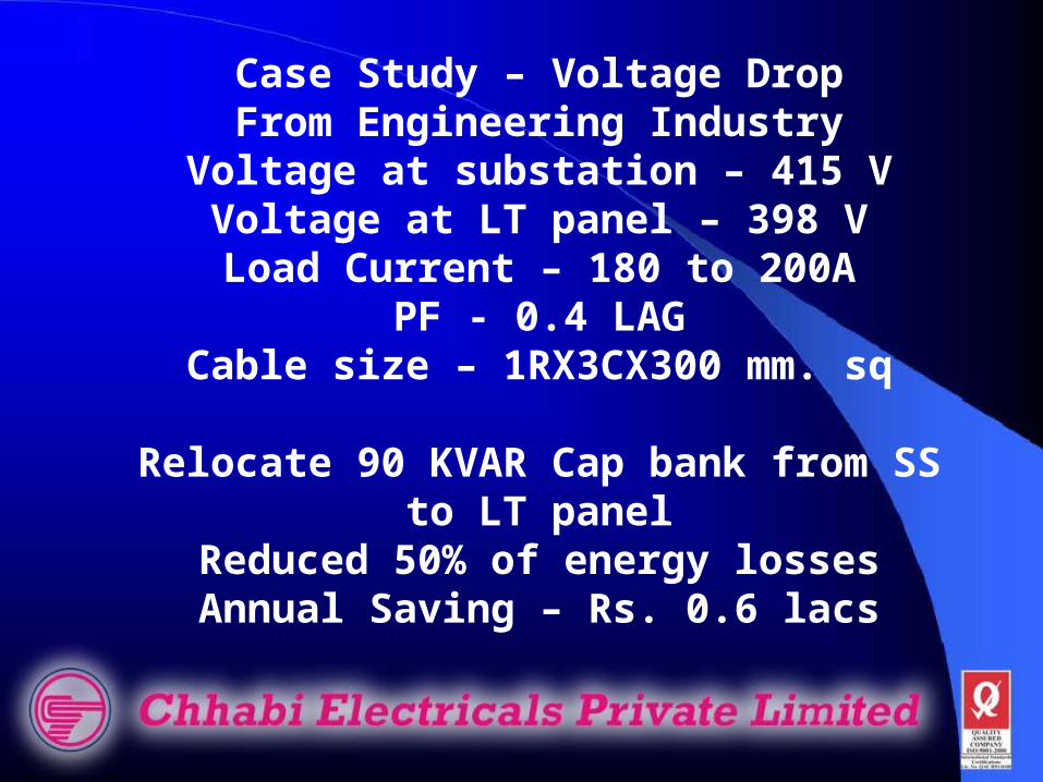
Case Study – Voltage DropFrom Engineering Industry
Voltage at substation – 415 VVoltage at LT panel – 398 VLoad Current – 180 to 200A
PF - 0.4 LAGCable size – 1RX3CX300 mm. sq
Relocate 90 KVAR Cap bank from SS to LT panel
Reduced 50% of energy lossesAnnual Saving – Rs. 0.6 lacs

Energy Conservation in Transformers
Transformer Efficiency – 98-99%Optimum Efficiency Occurs when
Iron Losses = Copper Losses(Optimum eff. Occurs between 40%
to 60 % of loading )
Selection of Transformer should be based on TOC
TOC = Price +(No load loss x loss value) +(load loss x loss value)

Three Phase Transformer Typical Loss ChartKVA Iron Loss FL Copper Loss500 1030 6860 750 1420 95001000 1770 118201250 1820 12000
*loss is in watts

CB
CB
2000KVA
11KV/433V
CB
CB
2000KVA
11KV/433V
11KV
415V
CASE STUDY

CASE STUDYBackground
*Cap of Xmer = 1600 KVA*Load on Xmer is 80 %
*Iron Loss = 2.3 kw*copper loss = 21 kw
Suggestion – Operate both transformer in parallel
*One Xmer operation loss = 2.3+21(0.8)2= 15.7 kw
*Both Xmer in operationloss = [2.3+21x(0.4)2]x2=11.3 kw
Annual Saving = Rs.0.78 lacs

THANK YOU


![Plant Conservation: Why it matters and how it works [Excerpt]](https://img.pdfslide.net/doc/110x75/577cd2ea1a28ab9e78964c28/plant-conservation-why-it-matters-and-how-it-works-excerpt.jpg)