Embed Size (px)
Citation preview
Energy Efficiency Simulation Study of Electric
Car Charging Stations Based on Double-mode
Xuejun Gong
Benxi Power Supply Branch
State Grid Liaoning Electric Power Supply Co. Ltd
Benxi, China
e-mail: [email protected]
Ling Wang
Benxi Power Supply Branch
State Grid Liaoning Electric Power Supply Co. Ltd Benxi, China
e-mail: [email protected]
Zhida Xu
Benxi Power Supply Branch
State Grid Liaoning Electric Power Supply Co. Ltd
Benxi, China
e-mail: [email protected]
Abstract—The effect of disordered electric vehicle charging
and discharging on security and economic operation of the
power system has serious negative effects. To avoid this
problem, the emulation system of electric car charging
stations is constructed according to the analysis of energy
efficiency of electric vehicle charging stations based on
double optimization. The whole energy efficiency of the
charging station can be divided into two factors: the first is charging function model. The actual work of their loss is
emulated in the different load conditions charger each
element based on a lithium-ion battery charging
characteristic curve typical charger establish energy model.
The second is energy efficiency model for charging stations.
the energy loss of charging station system is simulated
according to the type of charger, charging station power
mode energy consumption structure and configuration.
Keywords-energy efficiency; simulation; electric car;
charging stations; double-mode
I. INTRODUCTION
As an effective way to solve the energy security, environmental pollution and global warming, the electric car has a broad market prospect [1-5]. However, after a large number of electric vehicles that are widely used, if not for its coordination and control the charging and discharging behavior, it may endanger the safety and economic operation of power systems, increasing energy consumption. Electric vehicle charging station is a basic universal service facilities, and its energy efficiency situation to a large extent reflect the actual electric vehicle industry energy saving capabilities [6]. However, due to the electric car industry is just emerging electric vehicle charging station is accelerating construction, there is no unified energy efficiency evaluation criteria. Therefore, it is necessary to establish an appropriate and comprehensive evaluation system to assess the energy efficiency of electric vehicle charging station energy saving capabilities, the electric car industry to promote energy-efficient, zero emission direction [7-12].
Taking into account the electric vehicle charging load a certain controllable through optimized control over the charging process can reduce the adverse effects on the grid has gained recognition. A study of the literature of the future load characteristics charge electric vehicles in China, the calculated results show that the charge will increase system disorder peak load and poor valley, electric vehicle charging and discharging of optimal control and reduce energy consumption with greater potential. In this paper, electric vehicle charging stations to analyze the overall energy efficiency, with typical structures were built large and small charger charging machine model, which is the underlying model, namely a combination of large and small charging station, and ultimately to six sets of charging station simulation system; to The new topology (shared DC bus-powered mode) charging stations were set up large and small, eventually charging stations for three sets of simulation systems. Typical energy efficiency and the use of technology in the two charging stations, build several models. These models can be optimized for electric vehicle charging and discharging control and provide a reference implementation for building and economic operation of electric vehicle charging stations.
II. SIMULATION COMPONENTS MODELING
Charging station charging stations should be able to
follow the true underlying components starting to build transformers, power lines, power factor correction and reactive power compensation device, charger and lithium-ion battery energy efficiency models. The modeling of power electronic devices mainly involves capacitors, inductors and power switching devices.
A. Transformers
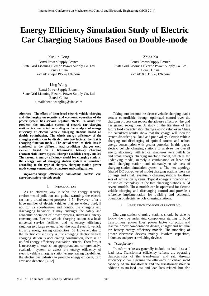
Transformer losses generally include no-load loss and load loss. Transformer efficiency reflects the operating characteristics of the transformer, and said through efficiency curve. Because the efficiency of certain rated capacity of the transformer and the transformer itself in addition to no-load loss and load loss related, but also
© 2014. The authors - Published by Atlantis Press 680
International Conference on Mechatronics, Control and Electronic Engineering (MCE 2014)
closely related to the power factor and load factor transformer load. Therefore, in practical application, the loss of influence of load power factor, load factor and harmonics of the transformer, the transformer model to establish energy efficiency is actually running.
Figure 1. Transformer efficiency and load factor
Figure 2. Transformer efficiency and power factor
B. Power Line
The loss of power lines and line length, line impedance load current and relevant. In the actual operation of the charging station, the load current and the actual use of the charging unit closely related to the line impedance is also affected by temperature and other factors. Therefore, the actual operation of the process to establish energy-efficient models in the charging station power lines, analyze losses under different working conditions of the line.
C. Battery
Since lithium-ion batteries have greater advantages in energy density, power density, cycle life, etc., so now widely used in electric vehicles. Lithium-ion batteries generally use the first constant current constant voltage charging method, starting with pre-given constant current charging of lithium-ion batteries, lithium-ion battery when the voltage reaches a certain value, and then to constant voltage charging. This method can guarantee the lithium-ion battery can accept larger in current fast charge constant current, but also ensures that the lithium-ion battery voltage is high then the constant voltage charging method, thereby gradually reduced current for lithium-ion battery charging, to protect the lithium-ion battery life. Because lithium-ion battery state of charge directly determine the working status of the charger, so the curve established models based on lithium-ion batteries lithium-ion battery charging characteristics.
D. Capacitors
In practice the capacitance of the "ideal" capacitors of different "real" capacitor due to its packaging, materials, etc., which is provided with an inductor, an additional characteristic resistance must be used additional "parasitic" elements or "non-ideal" to characterize the performance, the form of a resistance element and an inductance element, and a non-linear dielectric storage performance. To simulate the energy consumption of the project, must be the actual model.
E. Inductor
Inductor L model is equivalent to its value and series resistance ESR.
F. Power Device
Power device loss mainly by on-state losses, the opening loss and turn-off losses composition. On-state power loss is influenced by the load current of the device, and the switching losses associated with the switching speed of the device, the driving capacity of the device, the switch current, the switching voltage and switching frequency. Through in-depth study of the device switching characteristics and the mechanism of loss, loss model established different working status when power devices, choose the best machine for charging devices and circuit topology is of great significance.
III. CHARGER MAIN CIRCUIT TOPOLOGY AND
SIMULATION
A. Charger Topology Research
Since the charging machine topology, composition and method for controlling the difference between the key components will directly affect the power factor of the charging machine, the harmonic content of the current efficiency and other parameters. And as a charging station charger major electrical equipment, its level of efficiency for the energy efficiency of the charging station and intuitive important. Currently, the most widely used two typical charger and diode rectifier topology for high-frequency isolated DC-DC converter and PWM Rectifier and high frequency isolated DC-DC converter. Since the diode rectifier charger greater harmonics on the grid during the charging process causing pollution, the need to increase the effective harmonic and reactive power compensation device.
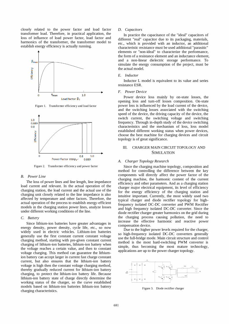
Due to the higher power levels required for the charger, so high-frequency isolated DC-DC converters generally use the full-bridge mode. Main circuit structure and control method is the most hard-switching PWM converter is simple, thus becoming the most mature technology, applications are up to the power charger topology.
L1
D1 D3 D5
D2 D4 D6
C1
T1 T2
T3 T4
L2
C2
D12
D11
AC
380V
Figure 3. Diode rectifier charger
681
L1
C1
T1 T2
T3 T4
L2
C2
D12
D11
AC
380V
T11
T12
T21
T22
T31
T32
Figure 4. PWM rectifier charger
B. charging machine simulation
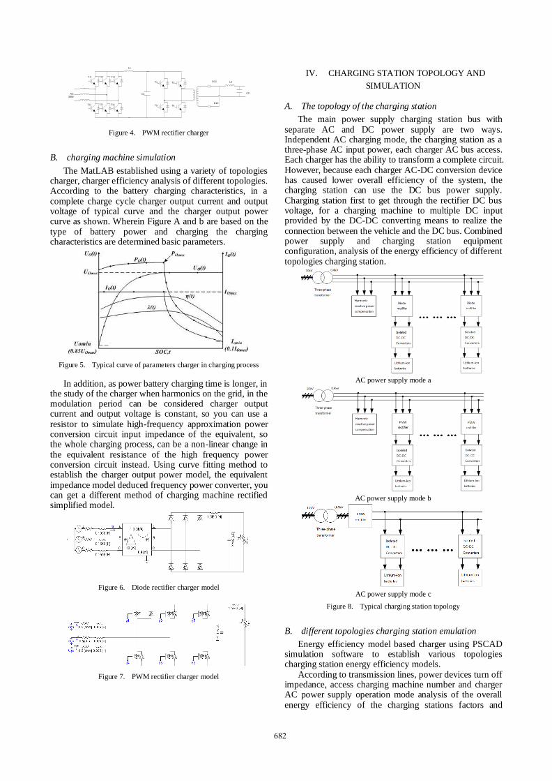
The MatLAB established using a variety of topologies charger, charger efficiency analysis of different topologies. According to the battery charging characteristics, in a complete charge cycle charger output current and output voltage of typical curve and the charger output power curve as shown. Wherein Figure A and b are based on the type of battery power and charging the charging characteristics are determined basic parameters.
Figure 5. Typical curve of parameters charger in charging process
In addition, as power battery charging time is longer, in the study of the charger when harmonics on the grid, in the modulation period can be considered charger output current and output voltage is constant, so you can use a resistor to simulate high-frequency approximation power conversion circuit input impedance of the equivalent, so the whole charging process, can be a non-linear change in the equivalent resistance of the high frequency power conversion circuit instead. Using curve fitting method to establish the charger output power model, the equivalent impedance model deduced frequency power converter, you can get a different method of charging machine rectified simplified model.
Figure 6. Diode rectifier charger model
Figure 7. PWM rectifier charger model
IV. CHARGING STATION TOPOLOGY AND
SIMULATION
A. The topology of the charging station
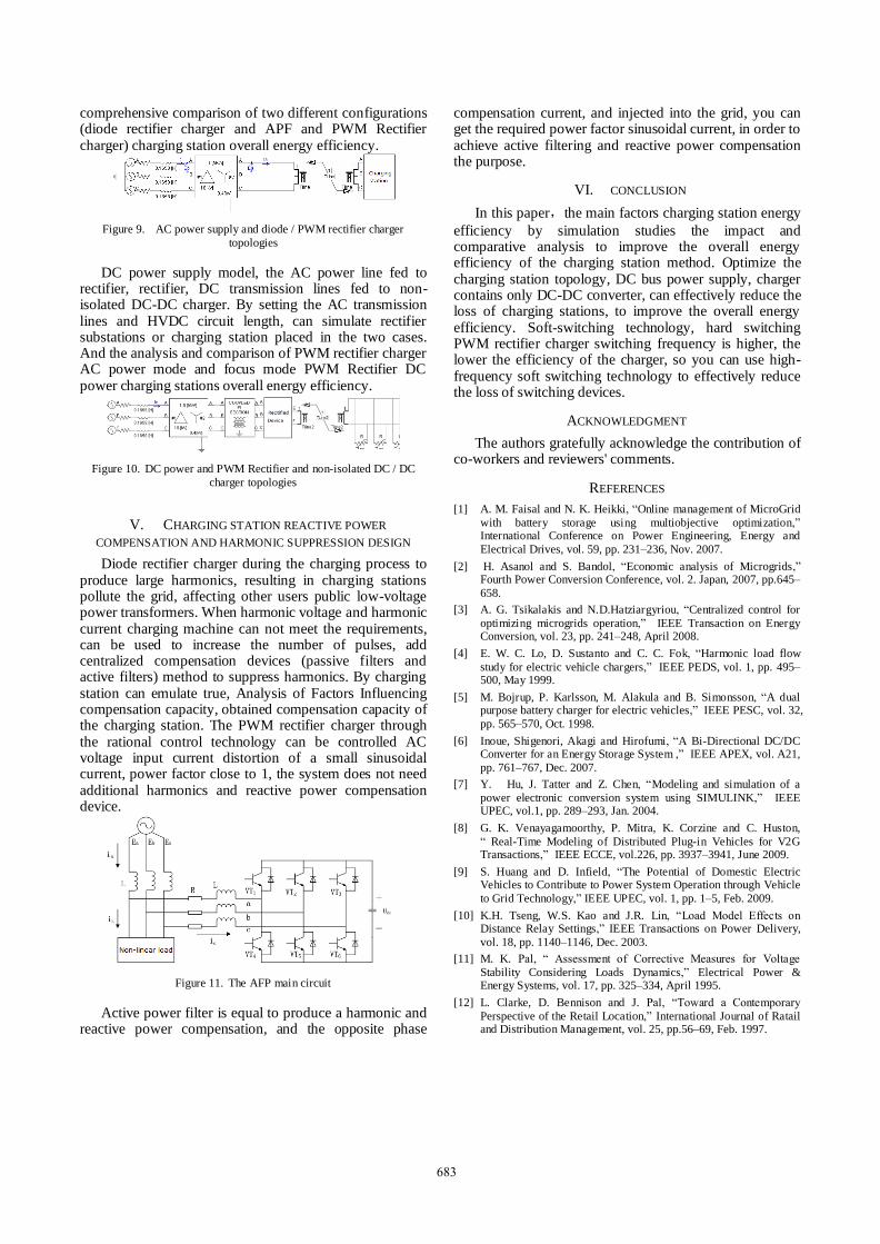
The main power supply charging station bus with separate AC and DC power supply are two ways. Independent AC charging mode, the charging station as a three-phase AC input power, each charger AC bus access. Each charger has the ability to transform a complete circuit. However, because each charger AC-DC conversion device has caused lower overall efficiency of the system, the charging station can use the DC bus power supply. Charging station first to get through the rectifier DC bus voltage, for a charging machine to multiple DC input provided by the DC-DC converting means to realize the connection between the vehicle and the DC bus. Combined power supply and charging station equipment configuration, analysis of the energy efficiency of different topologies charging station.
AC power supply mode a
AC power supply mode b
AC power supply mode c
Figure 8. Typical charging station topology
B. different topologies charging station emulation
Energy efficiency model based charger using PSCAD simulation software to establish various topologies charging station energy efficiency models.
According to transmission lines, power devices turn off impedance, access charging machine number and charger AC power supply operation mode analysis of the overall energy efficiency of the charging stations factors and
682
comprehensive comparison of two different configurations (diode rectifier charger and APF and PWM Rectifier charger) charging station overall energy efficiency.
Figure 9. AC power supply and diode / PWM rectifier charger
topologies
DC power supply model, the AC power line fed to rectifier, rectifier, DC transmission lines fed to non-isolated DC-DC charger. By setting the AC transmission lines and HVDC circuit length, can simulate rectifier substations or charging station placed in the two cases. And the analysis and comparison of PWM rectifier charger AC power mode and focus mode PWM Rectifier DC power charging stations overall energy efficiency.
Figure 10. DC power and PWM Rectifier and non-isolated DC / DC
charger topologies
V. CHARGING STATION REACTIVE POWER
COMPENSATION AND HARMONIC SUPPRESSION DESIGN
Diode rectifier charger during the charging process to produce large harmonics, resulting in charging stations pollute the grid, affecting other users public low-voltage power transformers. When harmonic voltage and harmonic current charging machine can not meet the requirements, can be used to increase the number of pulses, add centralized compensation devices (passive filters and active filters) method to suppress harmonics. By charging station can emulate true, Analysis of Factors Influencing compensation capacity, obtained compensation capacity of the charging station. The PWM rectifier charger through the rational control technology can be controlled AC voltage input current distortion of a small sinusoidal current, power factor close to 1, the system does not need additional harmonics and reactive power compensation device.
Figure 11. The AFP main circuit
Active power filter is equal to produce a harmonic and reactive power compensation, and the opposite phase
compensation current, and injected into the grid, you can get the required power factor sinusoidal current, in order to achieve active filtering and reactive power compensation the purpose.
VI. CONCLUSION
In this paper,the main factors charging station energy
efficiency by simulation studies the impact and comparative analysis to improve the overall energy efficiency of the charging station method. Optimize the charging station topology, DC bus power supply, charger contains only DC-DC converter, can effectively reduce the loss of charging stations, to improve the overall energy efficiency. Soft-switching technology, hard switching PWM rectifier charger switching frequency is higher, the lower the efficiency of the charger, so you can use high-frequency soft switching technology to effectively reduce the loss of switching devices.
ACKNOWLEDGMENT
The authors gratefully acknowledge the contribution of co-workers and reviewers' comments.
REFERENCES
[1] A. M. Faisal and N. K. Heikki, “Online management of MicroGrid
with battery storage using multiobjective optimization,” International Conference on Power Engineering, Energy and
Electrical Drives, vol. 59, pp. 231–236, Nov. 2007.
[2] H. Asanol and S. Bandol, “Economic analysis of Microgrids,” Fourth Power Conversion Conference, vol. 2. Japan, 2007, pp.645–
658.
[3] A. G. Tsikalakis and N.D.Hatziargyriou, “Centralized control for
optimizing microgrids operation,” IEEE Transaction on Energy Conversion, vol. 23, pp. 241–248, April 2008.
[4] E. W. C. Lo, D. Sustanto and C. C. Fok, “Harmonic load flow
study for electric vehicle chargers,” IEEE PEDS, vol. 1, pp. 495–500, May 1999.
[5] M. Bojrup, P. Karlsson, M. Alakula and B. Simonsson, “A dual purpose battery charger for electric vehicles,” IEEE PESC, vol. 32,
pp. 565–570, Oct. 1998.
[6] Inoue, Shigenori, Akagi and Hirofumi, “A Bi-Directional DC/DC Converter for an Energy Storage System ,” IEEE APEX, vol. A21,
pp. 761–767, Dec. 2007.
[7] Y. Hu, J. Tatter and Z. Chen, “Modeling and simulation of a
power electronic conversion system using SIMULINK,” IEEE UPEC, vol.1, pp. 289–293, Jan. 2004.
[8] G. K. Venayagamoorthy, P. Mitra, K. Corzine and C. Huston,
“ Real-Time Modeling of Distributed Plug-in Vehicles for V2G Transactions,” IEEE ECCE, vol.226, pp. 3937–3941, June 2009.
[9] S. Huang and D. Infield, “The Potential of Domestic Electric Vehicles to Contribute to Power System Operation through Vehicle
to Grid Technology,” IEEE UPEC, vol. 1, pp. 1–5, Feb. 2009.
[10] K.H. Tseng, W.S. Kao and J.R. Lin, “Load Model Effects on Distance Relay Settings,” IEEE Transactions on Power Delivery,
vol. 18, pp. 1140–1146, Dec. 2003.
[11] M. K. Pal, “ Assessment of Corrective Measures for Voltage
Stability Considering Loads Dynamics,” Electrical Power & Energy Systems, vol. 17, pp. 325–334, April 1995.
[12] L. Clarke, D. Bennison and J. Pal, “Toward a Contemporary
Perspective of the Retail Location,” International Journal of Ratail and Distribution Management, vol. 25, pp.56–69, Feb. 1997.
683