Embed Size (px)
Citation preview
Energy-Efficient Mission Planning of UAVsfor 5G Coverage in Rural Zones
Lavinia Amorosi,1 Luca Chiaraviglio,(1,2) Fabio D’Andreagiovanni,(3,4) Nicola Blefari-Melazzi,(1,2)
1) Consorzio Nazionale Interunivesitario per le Telecomunicazioni, Italy,2) EE Department, University of Rome Tor Vergata, Italy, email: [email protected]
3) National Center for Scientific Research (CNRS), France,4) Sorbonne Universites, Universite de Technologie de Compiegne, CNRS, HeudiasycUMR 7253, CS 60319, 60203 Compiegne, France, email: [email protected]
Abstract—We target the problem of providing 5G networkconnectivity in rural zones by means of Base Stations (BSs)carried by Unmanned Aerial Vehicles (UAVs). Our goal is toschedule the UAVs missions to: i) limit the amount of energyconsumed by each UAV, ii) ensure the coverage of selected zonesover the territory, ii) decide where and when each UAV has to berecharged in a ground site, iii) deal with the amount of energyprovided by Solar Panels (SPs) and batteries installed in eachground site. We then formulate the RURALPLAN optimizationproblem, a variant of the unsplittable multicommodity flowproblem defined on a multiperiod graph. After detailing theobjective function and the constraints, we solve RURALPLANin a realistic scenario. Results show that RURALPLAN is able tooutperform a solution ensuring coverage but not considering theenergy management of the UAVs.
I. INTRODUCTION
According to different studies, at least two billions peopleare experiencing a complete lack of Internet coverage [1].Such people are mostly living in rural zones, where thenetwork operators are not generally keen to invest, due tothe prohibitive deployment costs, as well as very low Returnon Investment (RoI) rates. This includes current technologiesfor deploying access networks, such as 3G/4G and FTTx,and the forthcoming 5G technology. Nevertheless, the lackof Internet connectivity is one of the major impairments forthe development of the United Nations (UNs) SustainableDevelopment Goals (SDGs) [2], [3].
Among the different solutions to reduce the Internet connec-tivity divide in rural and low income areas, one of the mostpromising is the exploitation of Unmanned Aerial Vehicles(UAVs) providing 5G coverage (see e.g., [4], [5], [6], [7]). Themain idea behind most of such approches is the deployment ofan opportunistic network, where the users associate to the BaseStations (BSs) carried by the flying UAVs. A radio networkbased on UAVs, in fact, introduces several advantages, inclu-ding: i) the possibility to cover only the zones of the territorywhere (and when) the users are located, ii) a general decreaseof the installation costs, thanks to the fact that multiple UAVscan share the same ground site to recharge themselves andto exchange data with the core of the network, and iii) theadoption of short-distance Line-of-Sight (Los) communicationchannels between the users and the UAV covering them.
Even though the deployment of UAV-based 5G networkarchitectures is a promising solution, its actual evaluation inreal-life scenarios is only at the early stage. In particular,when an UAV-based 5G architecture is assumed, differentkey questions arise, such as: i) How to cover a set of areaswith a set of UAV-based BSs? ii) How to efficiently managethe energy consumed by the UAV-based BSs? iii) How tomanage the energy coming from the Solar Panels (SPs) andthe batteries installed at the ground sites? iv) Is it possibleto define a model to take into account all the aforementionedaspects? The goal of this paper is to shed light on these issuesby:
1) considering a scenario in which a set of ground sites, aset of UAVs, and a set of areas that need to be coveredare given as input;
2) targeting the energy efficient management of the UAVsmissions, in order to minimize the energy that is con-sumed by the UAVs;
3) ensuring the coverage of the areas by efficiently sche-duling the UAVs missions over a set of multiple TimeSlots (TSs);
4) dealing with the battery levels of each ground site todecide where and when each UAV is recharged.
More in detail, we define an optimization problem, called RU-RALPLAN, with the goal of minimizing the energy consumedby the UAVs during the moving operations, while ensuringcoverage, energy consumption, and battery levels constraints.Results, obtained over a representative scenario, clearly showthat RURALPLAN is able to outperform a solution focusedsolely on the problem of providing coverage over the territory.
In recent times, the optimal planning and management ofnetworks made up of drones aimed at providing various kindof services such as surveillance, package delivery and networkconnectivity has received a lot of attention (see e.g., [8], [9],[10], [11]). Such optimization problems are closely relatedto the general problem of multi-period capacitated networkdesign, involving flow models on a graph [12]. In line withthis trend, RURALPLAN exploits a graph-based structure tomodel the UAVs missions.
The closest paper to our present work is [6], in which
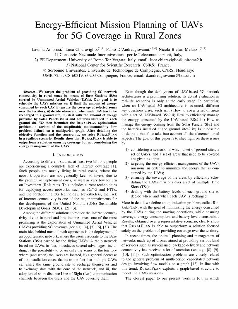
Site Battery Level at (t− 1)
+
SPs Energy at t
−
UAVs Recharging Energy at t
=
Site Battery Level at t
Fig. 1. Computation of the battery levels for one site at TS t
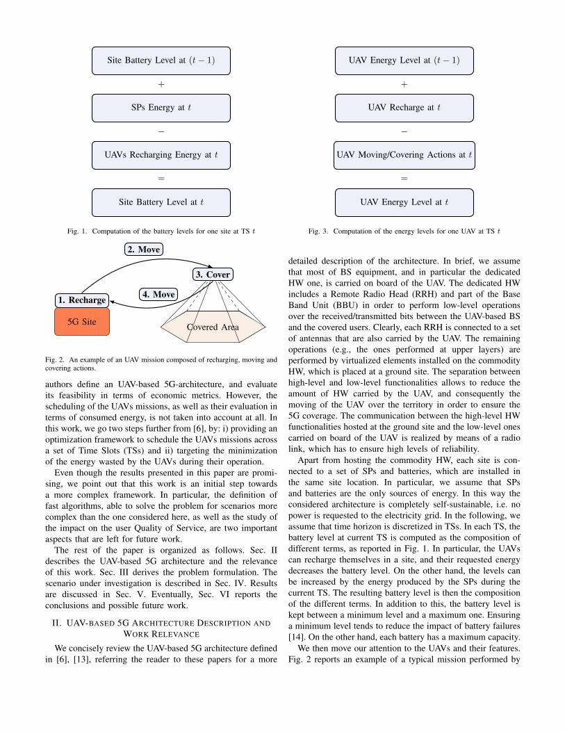
3. Cover
1. Recharge
5G Site
2. Move
4. Move
Covered Area
Fig. 2. An example of an UAV mission composed of recharging, moving andcovering actions.
authors define an UAV-based 5G-architecture, and evaluateits feasibility in terms of economic metrics. However, thescheduling of the UAVs missions, as well as their evaluation interms of consumed energy, is not taken into account at all. Inthis work, we go two steps further from [6], by: i) providing anoptimization framework to schedule the UAVs missions acrossa set of Time Slots (TSs) and ii) targeting the minimizationof the energy wasted by the UAVs during their operation.
Even though the results presented in this paper are promi-sing, we point out that this work is an initial step towardsa more complex framework. In particular, the definition offast algorithms, able to solve the problem for scenarios morecomplex than the one considered here, as well as the study ofthe impact on the user Quality of Service, are two importantaspects that are left for future work.
The rest of the paper is organized as follows. Sec. IIdescribes the UAV-based 5G architecture and the relevanceof this work. Sec. III derives the problem formulation. Thescenario under investigation is described in Sec. IV. Resultsare discussed in Sec. V. Eventually, Sec. VI reports theconclusions and possible future work.
II. UAV-BASED 5G ARCHITECTURE DESCRIPTION ANDWORK RELEVANCE
We concisely review the UAV-based 5G architecture definedin [6], [13], referring the reader to these papers for a more
UAV Energy Level at (t− 1)
+
UAV Recharge at t
−
UAV Moving/Covering Actions at t
=
UAV Energy Level at t
Fig. 3. Computation of the energy levels for one UAV at TS t
detailed description of the architecture. In brief, we assumethat most of BS equipment, and in particular the dedicatedHW one, is carried on board of the UAV. The dedicated HWincludes a Remote Radio Head (RRH) and part of the BaseBand Unit (BBU) in order to perform low-level operationsover the received/transmitted bits between the UAV-based BSand the covered users. Clearly, each RRH is connected to a setof antennas that are also carried by the UAV. The remainingoperations (e.g., the ones performed at upper layers) areperformed by virtualized elements installed on the commodityHW, which is placed at a ground site. The separation betweenhigh-level and low-level functionalities allows to reduce theamount of HW carried by the UAV, and consequently themoving of the UAV over the territory in order to ensure the5G coverage. The communication between the high-level HWfunctionalities hosted at the ground site and the low-level onescarried on board of the UAV is realized by means of a radiolink, which has to ensure high levels of reliability.
Apart from hosting the commodity HW, each site is con-nected to a set of SPs and batteries, which are installed inthe same site location. In particular, we assume that SPsand batteries are the only sources of energy. In this way theconsidered architecture is completely self-sustainable, i.e. nopower is requested to the electricity grid. In the following, weassume that time horizon is discretized in TSs. In each TS, thebattery level at current TS is computed as the composition ofdifferent terms, as reported in Fig. 1. In particular, the UAVscan recharge themselves in a site, and their requested energydecreases the battery level. On the other hand, the levels canbe increased by the energy produced by the SPs during thecurrent TS. The resulting battery level is then the compositionof the different terms. In addition to this, the battery level iskept between a minimum level and a maximum one. Ensuringa minimum level tends to reduce the impact of battery failures[14]. On the other hand, each battery has a maximum capacity.
We then move our attention to the UAVs and their features.Fig. 2 reports an example of a typical mission performed by
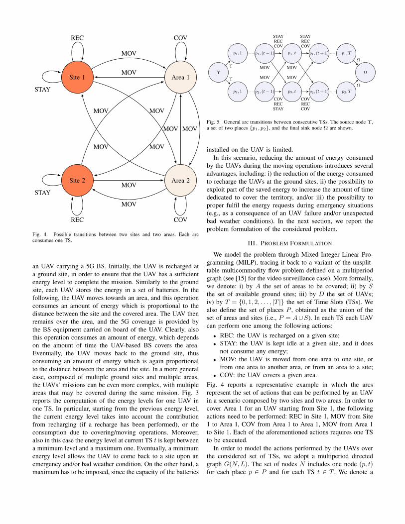
Site 1 Area 1
Site 2 Area 2
STAY
STAY
MOV
MOV
COVREC
MOV
MOV
COVREC
MOV
MOV
MOVMOV
MOV
MOV
Fig. 4. Possible transitions between two sites and two areas. Each arcconsumes one TS.
an UAV carrying a 5G BS. Initially, the UAV is recharged ata ground site, in order to ensure that the UAV has a sufficientenergy level to complete the mission. Similarly to the groundsite, each UAV stores the energy in a set of batteries. In thefollowing, the UAV moves towards an area, and this operationconsumes an amount of energy which is proportional to thedistance between the site and the covered area. The UAV thenremains over the area, and the 5G coverage is provided bythe BS equipment carried on board of the UAV. Clearly, alsothis operation consumes an amount of energy, which dependson the amount of time the UAV-based BS covers the area.Eventually, the UAV moves back to the ground site, thusconsuming an amount of energy which is again proportionalto the distance between the area and the site. In a more generalcase, composed of multiple ground sites and multiple areas,the UAVs’ missions can be even more complex, with multipleareas that may be covered during the same mission. Fig. 3reports the computation of the energy levels for one UAV inone TS. In particular, starting from the previous energy level,the current energy level takes into account the contributionfrom recharging (if a recharge has been performed), or theconsumption due to covering/moving operations. Moreover,also in this case the energy level at current TS t is kept betweena minimum level and a maximum one. Eventually, a minimumenergy level allows the UAV to come back to a site upon anemergency and/or bad weather condition. On the other hand, amaximum has to be imposed, since the capacity of the batteries
Ω
p1, T
p2, T
p1, (t + 1)
p2, (t + 1)
p1, t
p2, t
p1, (t− 1)
p2, (t− 1)
MOV
MOV
MOV
MOV
p1, 1
p2, 1
Υ
STAYRECCOV
COVRECSTAY
STAYRECCOV
COVRECCOV
Ω
Ω
Υ
Υ
Fig. 5. General arc transitions between consecutive TSs. The source node Υ,a set of two places p1, p2, and the final sink node Ω are shown.
installed on the UAV is limited.In this scenario, reducing the amount of energy consumed
by the UAVs during the moving operations introduces severaladvantages, including: i) the reduction of the energy consumedto recharge the UAVs at the ground sites, ii) the possibility toexploit part of the saved energy to increase the amount of timededicated to cover the territory, and/or iii) the possibility toproper fulfil the energy requests during emergency situations(e.g., as a consequence of an UAV failure and/or unexpectedbad weather conditions). In the next section, we report theproblem formulation of the considered problem.
III. PROBLEM FORMULATION
We model the problem through Mixed Integer Linear Pro-gramming (MILP), tracing it back to a variant of the unsplit-table multicommodity flow problem defined on a multiperiodgraph (see [15] for the video surveillance case). More formally,we denote: i) by A the set of areas to be covered; ii) by Sthe set of available ground sites; iii) by D the set of UAVs;iv) by T = 0, 1, 2, . . . , |T | the set of Time Slots (TSs). Wealso define the set of places P , obtained as the union of theset of areas and sites (i.e., P = A∪S). In each TS each UAVcan perform one among the following actions:• REC: the UAV is recharged on a given site;• STAY: the UAV is kept idle at a given site, and it does
not consume any energy;• MOV: the UAV is moved from one area to one site, or
from one area to another area, or from an area to a site;• COV: the UAV covers a given area.
Fig. 4 reports a representative example in which the arcsrepresent the set of actions that can be performed by an UAVin a scenario composed by two sites and two areas. In order tocover Area 1 for an UAV starting from Site 1, the followingactions need to be performed: REC in Site 1, MOV from Site1 to Area 1, COV from Area 1 to Area 1, MOV from Area 1to Site 1. Each of the aforementioned actions requires one TSto be executed.
In order to model the actions performed by the UAVs overthe considered set of TSs, we adopt a multiperiod directedgraph G(N,L). The set of nodes N includes one node (p, t)for each place p ∈ P and for each TS t ∈ T . We denote a
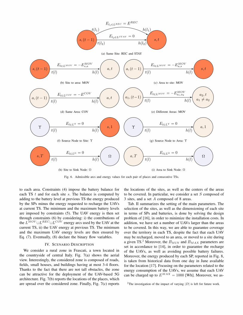
generic arc l ∈ L by [(p1, t1), (p2, t2)], where t(l) = (p1, t1)and h(l) = (p2, t2) are the tail and the head of the arc,respectively. We then introduce the set of arcs LREC , LSTAY ,LMOV and LCOV to denote the admissible transitions betweeneach place p1 at TS t1 and each other place p2 at TS t2 for therecharging, staying, moving and coverage actions, respectively.
Fig. 5 shows the admissible arcs for a toy case examplecomposed of two places. Apart from the nodes defined foreach pair (p, t) the graph also includes the fictitious nodes Υand Ω, which are used to keep track of the missions performedby the UAVs across the set of TSs. Our idea is in fact toassociate a binary flow variable for each arc and each UAV,and to impose a flow conservation constraint starting in Υand ending in Ω. The advantage of using the source node Υ isthat the problem is able to automatically choose the optimalplacement of the UAVs already during the first TS, withoutthe need of manually specifying it. In other words, we placea number of tokens in Υ equal to the number of UAVs. Inprinciple, each token corresponds to an UAV. The problemthen automatically selects which flow variables are activatedin order to preserve the token continuity until the Ω node.In particular, the Ω node allows to check that all the tokensare correctly received, i.e., the problem has considered all theUAVs until the final TS. The connections between the node Υand the node Ω are realized through the set or arcs LΥ and LΩ.The union of sets LREC∪LSTAY ∪LMOV ∪LCOV ∪LΥ∪LΩ
defines the entire set of links L.In the following, we associate an energy weight for each
arc in L. Fig. 6 reports the admissible arcs and the energyvalues for each pair of places and consecutive TSs. More indetail, two arcs are defined when the UAV is kept on the samesite between TS (t− 1) and TS t, as reported in Fig. 6(a). Inthe first case, there is one link l ∈ LREC , whose weight isequal to the energy consumed for recharging an UAV, denotedwith EREC . Alternatively, there is the possibility to keep theUAV on the site without any energy consumption throughthe link l ∈ LSTAY . In addition, when the UAV is movedfrom a site s ∈ S to an area a ∈ A (Fig. 6(b)), an arcl ∈ LMOV is defined.1 In this case, the weight of the arcis equal to −EMOV
s,a , where EMOVs,a denotes the amount of
energy consumed for moving the UAV from site s to areaa. Similarly, when the UAV is moved from an area a to asite s, another arc l ∈ LMOV is introduced, whose weight isequal −EMOV
a,s (Fig. 6(c)). On the other hand, when the areais not changed, a coverage action is performed (Fig. 6(d)). Inthis case, the corresponding arc l ∈ LCOV has a weight of−ECOV , where ECOV denotes the amount of energy spentto cover an area in one TS. Eventually, when the UAV passesfrom area a1 ∈ A to a different area a2 ∈ A (Fig. 6(e)), anarc l ∈ LMOV with weight −EMOV
a1,a2is introduced. Finally,
the arcs connecting Υ and Ω to the other nodes are defined inFig. 6(f)-6(i). Clearly, such arcs do not consume any amountof energy since both Υ and Ω are fictitious nodes.
1The set LMOV may not include all the possible links between each pairof places. This occurs, e.g., when a maximum distance between an UAV andthe ground site has to be ensured.
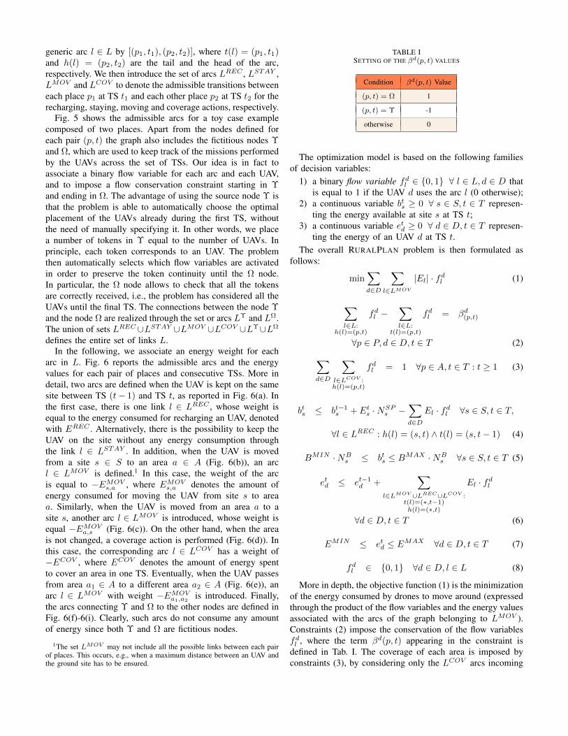
TABLE ISETTING OF THE βd(p, t) VALUES
Condition βd(p, t) Value
(p, t) = Ω 1
(p, t) = Υ -1
otherwise 0
The optimization model is based on the following familiesof decision variables:
1) a binary flow variable fdl ∈ 0, 1 ∀ l ∈ L, d ∈ D thatis equal to 1 if the UAV d uses the arc l (0 otherwise);
2) a continuous variable bts ≥ 0 ∀ s ∈ S, t ∈ T represen-ting the energy available at site s at TS t;
3) a continuous variable etd ≥ 0 ∀ d ∈ D, t ∈ T represen-ting the energy of an UAV d at TS t.
The overall RURALPLAN problem is then formulated asfollows:
min∑d∈D
∑l∈LMOV
|El| · fdl (1)
∑l∈L:
h(l)=(p,t)
fdl −∑l∈L:
t(l)=(p,t)
fdl = βd(p,t)
∀p ∈ P, d ∈ D, t ∈ T (2)∑d∈D
∑l∈LCOV :h(l)=(p,t)
fdl = 1 ∀p ∈ A, t ∈ T : t ≥ 1 (3)
bts ≤ bt−1s + Et
s ·NSPs −
∑d∈D
El · fdl ∀s ∈ S, t ∈ T,
∀l ∈ LREC : h(l) = (s, t) ∧ t(l) = (s, t− 1) (4)
BMIN ·NBs ≤ bts ≤ BMAX ·NB
s ∀s ∈ S, t ∈ T (5)
etd ≤ et−1d +
∑l∈LMOV ∪LREC∪LCOV :
t(l)=(∗,t−1)h(l)=(∗,t)
El · fdl
∀d ∈ D, t ∈ T (6)
EMIN ≤ etd ≤ EMAX ∀d ∈ D, t ∈ T (7)
fdl ∈ 0, 1 ∀d ∈ D, l ∈ L (8)
More in depth, the objective function (1) is the minimizationof the energy consumed by drones to move around (expressedthrough the product of the flow variables and the energy valuesassociated with the arcs of the graph belonging to LMOV ).Constraints (2) impose the conservation of the flow variablesfdl , where the term βd(p, t) appearing in the constraint isdefined in Tab. I. The coverage of each area is imposed byconstraints (3), by considering only the LCOV arcs incoming
s, (t− 1) s, t
El1∈LREC = EREC
El2∈LSTAY = 0
t(l2) h(l2)
t(l1) h(l1)
(a) Same Site: REC and STAY
s, (t− 1) a, tt(l) h(l)
El∈LMOV = −EMOVs,a
(b) Site to area: MOV
a, (t− 1) s, tt(l) h(l)
El∈LMOV = −EMOVa,s
(c) Area to site: MOV
a, (t− 1) a, tt(l) h(l)
El∈LCOV = −ECOV
(d) Same Area: COV
a1, (t−1)a2, t
a1 6= a2t(l) h(l)
El∈LMOV = −EMOVa1,a2
(e) Different Areas: MOV
Υ s, 1t(l) h(l)
El∈LΥ = 0
(f) Source Node to Site: Υ
Υ a, 1t(l) h(l)
El∈LΥ = 0
(g) Source Node to Area: Υ
s, T Ωt(l) h(l)
El∈LΩ = 0
(h) Site to Sink Node: Ω
a, T Ωt(l) h(l)
El∈LΩ = 0
(i) Area to Sink Node: Ω
Fig. 6. Admissible arcs and energy values for each pair of places and consecutive TSs.
to each area. Constraints (4) impose the battery balance foreach TS t and for each site s. The balance is computed byadding to the battery level at previous TS the energy producedby the SPs minus the energy requested to recharge the UAVsat current TS. The minimum and the maximum battery levelsare imposed by constraints (5). The UAV energy is then setthrough constraints (6) by considering: i) the contributions ofthe LMOV ∪LREC∪LCOV energy arcs used by the UAV at thecurrent TS, ii) the UAV energy at previous TS. The minimumand the maximum UAV energy levels are then ensured byEq. (7). Eventually, (8) declare the binary flow variables.
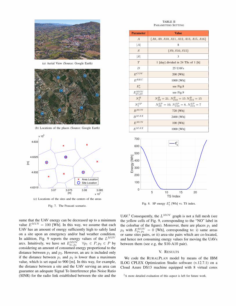
IV. SCENARIO DESCRIPTION
We consider a rural zone in Frascati, a town located inthe countryside of central Italy. Fig. 7(a) shows the aerialview. Interestingly, the considered zone is composed of roads,fields, small houses, and buildings having at most 3-4 floors.Thanks to the fact that there are not tall obstacles, the zonecan be attractive for the deployment of the UAV-based 5Garchitecture. Fig. 7(b) reports the locations of the places, whichare spread over the considered zone. Finally, Fig. 7(c) reports
the locations of the sites, as well as the centers of the areasto be covered. In particular, we consider a set S composed of3 sites, and a set A composed of 8 areas.
Tab. II summarizes the setting of the main parameters. Theselection of the sites, as well as the dimensioning of each sitein terms of SPs and batteries, is done by solving the designproblem of [16], in order to minimize the installation costs. Inaddition, we have set a number of UAVs larger than the areasto be covered. In this way, we are able to guarantee coverageover the territory in each TS, despite the fact that each UAVmay be recharged, moved to an area, or moved to a site duringa given TS.2 Moreover, the BMIN and BMAX parameters areset in accordance to [14], in order to guarantee the rechargeof the UAVs, as well as avoiding possible battery failures.Moreover, the energy produced by each SP, reported in Fig. 8,is taken from historical data from one day in June availablefor the location [17]. Focusing on the parameters related to theenergy consumption of the UAVs, we assume that each UAVcan be charged up to EMAX = 1000 [Wh]. Moreover, we as-
2The investigation of the impact of varying |D| is left for future work.
(a) Aerial View (Source: Google Earth)
(b) Locations of the places (Source: Google Earth)
3.07 3.075 3.08 3.085
x 105
4.6315
4.632
4.6325
4.633
x 106
[m]
[m]
Area Location
Site Location
(c) Locations of the sites and the centers of the areas
Fig. 7. The Frascati scenario.
sume that the UAV energy can be decreased up to a minimumvalue EMIN = 100 [Wh]. In this way, we assume that eachUAV has an amount of energy sufficiently high to safely landon a site upon an emergency and/or bad weather condition.In addition, Fig. 9 reports the energy values of the LMOV
arcs. Intuitively, we have set EMOVp1,p2
∀p1 ∈ P, p2 ∈ P byconsidering an amount of consumed energy proportional to thedistance between p1 and p2. However, an arc is included onlyif the distance between p1 and p2 is lower than a maximumvalue, which is set equal to 900 [m]. In this way, for example,the distance between a site and the UAV serving an area canguarantee an adequate Signal To Interference plus Noise Ratio(SINR) for the radio link established between the site and the
TABLE IIPARAMETERS SETTING
Parameter Value
A A8, A9, A10, A11, A12, A13, A15, A16
|A| 8
S S9, S10, S15
|S| 3
T 1 [day] divided in 24 TSs of 1 [h]
D 25 UAVs
ECOV 200 [Wh]
EREC 1000 [Wh]
Ets see Fig.8
EMOVp1,p2 see Fig.9
NBs NB
S9 = 21, NBS10 = 15 NB
S15 = 15
NSPs NSP
S9 = 10, NSPS10 = 8, NSP
S15 = 7
BMIN 720 [Wh]
BMAX 2400 [Wh]
EMIN 100 [Wh]
EMAX 1000 [Wh]
5 10 15 20
TS Index
0
100
200
300
400
500
600
700
Energ
y [W
h]
Es
t
Fig. 8. SP energy Ets [Wh] vs. TS index.
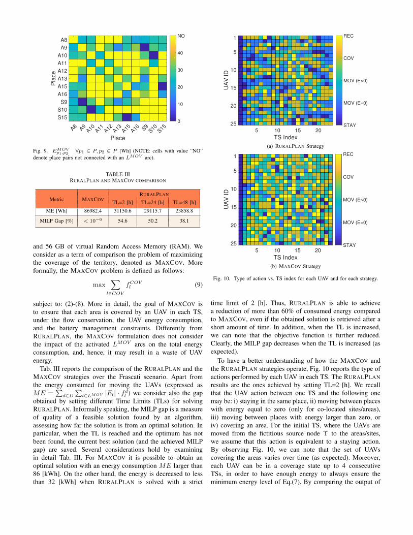
UAV.3 Consequently, the LMOV graph is not a full mesh (seethe yellow cells of Fig. 9, corresponding to the “NO” label inthe colorbar of the figure). Moreover, there are places p1 andp2 with EMOV
p1,p2= 0 [Wh], corresponding to: i) same areas
or same sites pairs, or ii) area-site pairs which are co-located,and hence not consuming energy values for moving the UAVsbetween them (see e.g, the S10-A10 pair).
V. RESULTS
We code the RURALPLAN model by means of the IBMILOG CPLEX Optimization Studio software (v.12.7.1) on aCloud Azure DS13 machine equipped with 8 virtual cores
3A more detailed evaluation of this aspect is left for future work.
A8 A9A10 A11 A12 A13 A15 A16 S9
S10 S15
Place
A8
A9
A10
A11
A12
A13
A15
A16
S9
S10
S15
Pla
ce
0
10
20
30
40
NO
Fig. 9. EMOVp1,p2
∀p1 ∈ P, p2 ∈ P [Wh] (NOTE: cells with value ”NO”denote place pairs not connected with an LMOV arc).
TABLE IIIRURALPLAN AND MAXCOV COMPARISON
RURALPLANMetric MAXCOV TL=2 [h] TL=24 [h] TL=48 [h]
ME [Wh] 86982.4 31150.6 29115.7 23858.8
MILP Gap [%] < 10−6 54.6 50.2 38.1
and 56 GB of virtual Random Access Memory (RAM). Weconsider as a term of comparison the problem of maximizingthe coverage of the territory, denoted as MAXCOV. Moreformally, the MAXCOV problem is defined as follows:
max∑
l∈COV
fCOVl (9)
subject to: (2)-(8). More in detail, the goal of MAXCOV isto ensure that each area is covered by an UAV in each TS,under the flow conservation, the UAV energy consumption,and the battery management constraints. Differently fromRURALPLAN, the MAXCOV formulation does not considerthe impact of the activated LMOV arcs on the total energyconsumption, and, hence, it may result in a waste of UAVenergy.
Tab. III reports the comparison of the RURALPLAN and theMAXCOV strategies over the Frascati scenario. Apart fromthe energy consumed for moving the UAVs (expressed asME =
∑d∈D
∑l∈LMOV |El| · fdl ) we consider also the gap
obtained by setting different Time Limits (TLs) for solvingRURALPLAN. Informally speaking, the MILP gap is a measureof quality of a feasible solution found by an algorithm,assessing how far the solution is from an optimal solution. Inparticular, when the TL is reached and the optimum has notbeen found, the current best solution (and the achieved MILPgap) are saved. Several considerations hold by examiningin detail Tab. III. For MAXCOV it is possible to obtain anoptimal solution with an energy consumption ME larger than86 [kWh]. On the other hand, the energy is decreased to lessthan 32 [kWh] when RURALPLAN is solved with a strict
5 10 15 20
TS Index
1
5
10
15
20
25
UA
V ID
STAY
MOV (E=0)
MOV (E>0)
COV
REC
(a) RURALPLAN Strategy
5 10 15 20
TS Index
1
5
10
15
20
25
UA
V ID
STAY
MOV (E=0)
MOV (E>0)
COV
REC
(b) MAXCOV Strategy
Fig. 10. Type of action vs. TS index for each UAV and for each strategy.
time limit of 2 [h]. Thus, RURALPLAN is able to achievea reduction of more than 60% of consumed energy comparedto MAXCOV, even if the obtained solution is retrieved after ashort amount of time. In addition, when the TL is increased,we can note that the objective function is further reduced.Clearly, the MILP gap decreases when the TL is increased (asexpected).
To have a better understanding of how the MAXCOV andthe RURALPLAN strategies operate, Fig. 10 reports the type ofactions performed by each UAV in each TS. The RURALPLANresults are the ones achieved by setting TL=2 [h]. We recallthat the UAV action between one TS and the following onemay be: i) staying in the same place, ii) moving between placeswith energy equal to zero (only for co-located sites/areas),iii) moving between places with energy larger than zero, oriv) covering an area. For the initial TS, where the UAVs aremoved from the fictitious source node Υ to the areas/sites,we assume that this action is equivalent to a staying action.By observing Fig. 10, we can note that the set of UAVscovering the areas varies over time (as expected). Moreover,each UAV can be in a coverage state up to 4 consecutiveTSs, in order to have enough energy to always ensure theminimum energy level of Eq.(7). By comparing the output of
5 10 15 20
TS Index
5
10
15
20
25
UA
V ID
100
200
300
400
500
600
700
800
900
1000
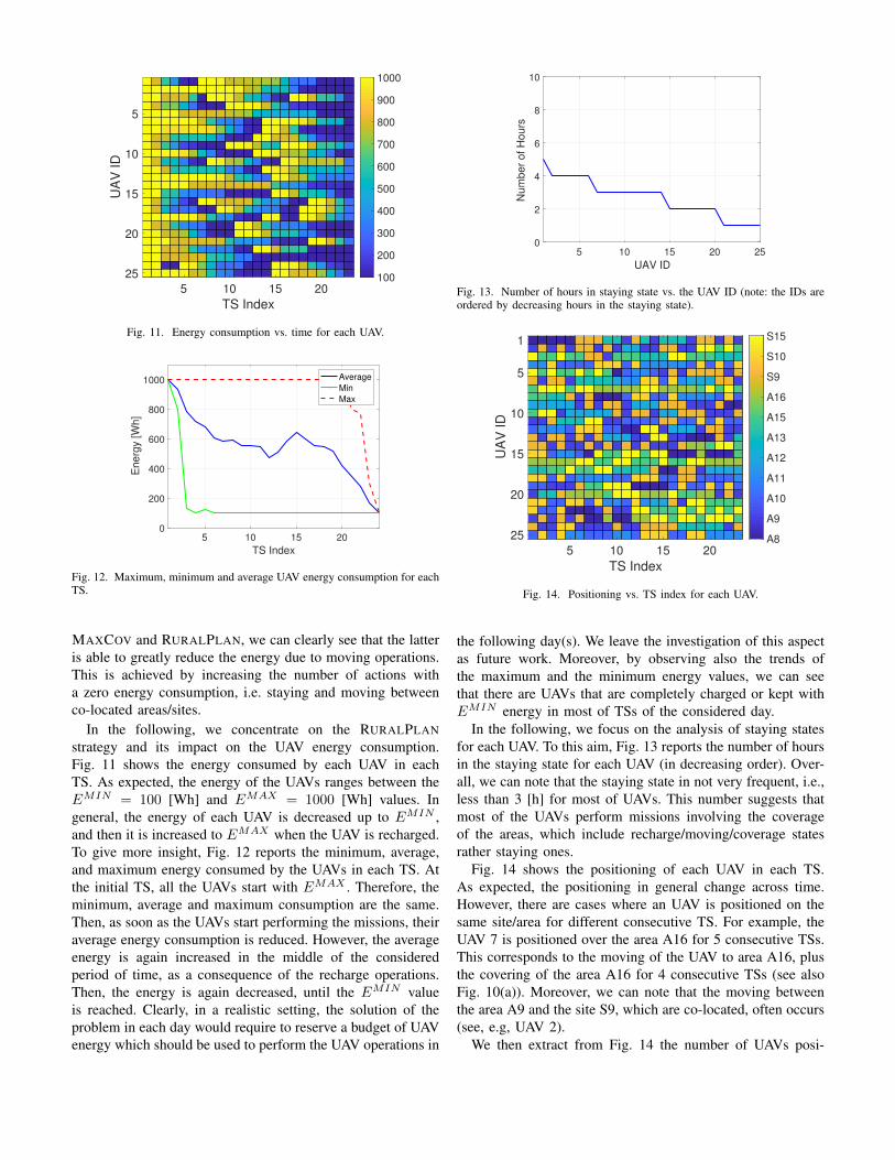
Fig. 11. Energy consumption vs. time for each UAV.
5 10 15 20
TS Index
0
200
400
600
800
1000
Energ
y [W
h]
Average
Min
Max
Fig. 12. Maximum, minimum and average UAV energy consumption for eachTS.
MAXCOV and RURALPLAN, we can clearly see that the latteris able to greatly reduce the energy due to moving operations.This is achieved by increasing the number of actions witha zero energy consumption, i.e. staying and moving betweenco-located areas/sites.
In the following, we concentrate on the RURALPLANstrategy and its impact on the UAV energy consumption.Fig. 11 shows the energy consumed by each UAV in eachTS. As expected, the energy of the UAVs ranges between theEMIN = 100 [Wh] and EMAX = 1000 [Wh] values. Ingeneral, the energy of each UAV is decreased up to EMIN ,and then it is increased to EMAX when the UAV is recharged.To give more insight, Fig. 12 reports the minimum, average,and maximum energy consumed by the UAVs in each TS. Atthe initial TS, all the UAVs start with EMAX . Therefore, theminimum, average and maximum consumption are the same.Then, as soon as the UAVs start performing the missions, theiraverage energy consumption is reduced. However, the averageenergy is again increased in the middle of the consideredperiod of time, as a consequence of the recharge operations.Then, the energy is again decreased, until the EMIN valueis reached. Clearly, in a realistic setting, the solution of theproblem in each day would require to reserve a budget of UAVenergy which should be used to perform the UAV operations in
5 10 15 20 25
UAV ID
0
2
4
6
8
10
Num
ber
of
Ho
urs
Fig. 13. Number of hours in staying state vs. the UAV ID (note: the IDs areordered by decreasing hours in the staying state).
5 10 15 20
TS Index
1
5
10
15
20
25
UA
V ID
A8
A9
A10
A11
A12
A13
A15
A16
S9
S10
S15
Fig. 14. Positioning vs. TS index for each UAV.
the following day(s). We leave the investigation of this aspectas future work. Moreover, by observing also the trends ofthe maximum and the minimum energy values, we can seethat there are UAVs that are completely charged or kept withEMIN energy in most of TSs of the considered day.
In the following, we focus on the analysis of staying statesfor each UAV. To this aim, Fig. 13 reports the number of hoursin the staying state for each UAV (in decreasing order). Over-all, we can note that the staying state in not very frequent, i.e.,less than 3 [h] for most of UAVs. This number suggests thatmost of the UAVs perform missions involving the coverageof the areas, which include recharge/moving/coverage statesrather staying ones.
Fig. 14 shows the positioning of each UAV in each TS.As expected, the positioning in general change across time.However, there are cases where an UAV is positioned on thesame site/area for different consecutive TS. For example, theUAV 7 is positioned over the area A16 for 5 consecutive TSs.This corresponds to the moving of the UAV to area A16, plusthe covering of the area A16 for 4 consecutive TSs (see alsoFig. 10(a)). Moreover, we can note that the moving betweenthe area A9 and the site S9, which are co-located, often occurs(see, e.g, UAV 2).
We then extract from Fig. 14 the number of UAVs posi-
5 10 15 20
TS Index
0
1
2
3
4
5
6
Num
ber
of U
AV
s
S9
S10
S15
Fig. 15. Number of UAVs per site vs. TS index.
5 10 15 20
TS Index
A8
A9
A10
A11
A12
A13
A15
A16
Are
a
1
2
3
4
5
6
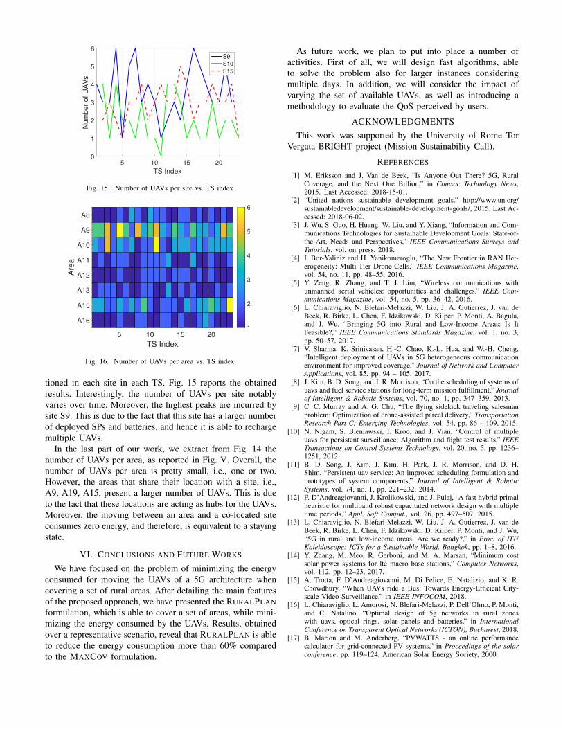
Fig. 16. Number of UAVs per area vs. TS index.
tioned in each site in each TS. Fig. 15 reports the obtainedresults. Interestingly, the number of UAVs per site notablyvaries over time. Moreover, the highest peaks are incurred bysite S9. This is due to the fact that this site has a larger numberof deployed SPs and batteries, and hence it is able to rechargemultiple UAVs.
In the last part of our work, we extract from Fig. 14 thenumber of UAVs per area, as reported in Fig. V. Overall, thenumber of UAVs per area is pretty small, i.e., one or two.However, the areas that share their location with a site, i.e.,A9, A19, A15, present a larger number of UAVs. This is dueto the fact that these locations are acting as hubs for the UAVs.Moreover, the moving between an area and a co-located siteconsumes zero energy, and therefore, is equivalent to a stayingstate.
VI. CONCLUSIONS AND FUTURE WORKS
We have focused on the problem of minimizing the energyconsumed for moving the UAVs of a 5G architecture whencovering a set of rural areas. After detailing the main featuresof the proposed approach, we have presented the RURALPLANformulation, which is able to cover a set of areas, while mini-mizing the energy consumed by the UAVs. Results, obtainedover a representative scenario, reveal that RURALPLAN is ableto reduce the energy consumption more than 60% comparedto the MAXCOV formulation.
As future work, we plan to put into place a number ofactivities. First of all, we will design fast algorithms, ableto solve the problem also for larger instances consideringmultiple days. In addition, we will consider the impact ofvarying the set of available UAVs, as well as introducing amethodology to evaluate the QoS perceived by users.
ACKNOWLEDGMENTSThis work was supported by the University of Rome Tor
Vergata BRIGHT project (Mission Sustainability Call).
REFERENCES
[1] M. Eriksson and J. Van de Beek, “Is Anyone Out There? 5G, RuralCoverage, and the Next One Billion,” in Comsoc Technology News,2015. Last Accessed: 2018-15-01.
[2] “United nations sustainable development goals.” http://www.un.org/sustainabledevelopment/sustainable-development-goals/, 2015. Last Ac-cessed: 2018-06-02.
[3] J. Wu, S. Guo, H. Huang, W. Liu, and Y. Xiang, “Information and Com-munications Technologies for Sustainable Development Goals: State-of-the-Art, Needs and Perspectives,” IEEE Communications Surveys andTutorials, vol. on press, 2018.
[4] I. Bor-Yaliniz and H. Yanikomeroglu, “The New Frontier in RAN Het-erogeneity: Multi-Tier Drone-Cells,” IEEE Communications Magazine,vol. 54, no. 11, pp. 48–55, 2016.
[5] Y. Zeng, R. Zhang, and T. J. Lim, “Wireless communications withunmanned aerial vehicles: opportunities and challenges,” IEEE Com-munications Magazine, vol. 54, no. 5, pp. 36–42, 2016.
[6] L. Chiaraviglio, N. Blefari-Melazzi, W. Liu, J. A. Gutierrez, J. van deBeek, R. Birke, L. Chen, F. Idzikowski, D. Kilper, P. Monti, A. Bagula,and J. Wu, “Bringing 5G into Rural and Low-Income Areas: Is ItFeasible?,” IEEE Communications Standards Magazine, vol. 1, no. 3,pp. 50–57, 2017.
[7] V. Sharma, K. Srinivasan, H.-C. Chao, K.-L. Hua, and W.-H. Cheng,“Intelligent deployment of UAVs in 5G heterogeneous communicationenvironment for improved coverage,” Journal of Network and ComputerApplications, vol. 85, pp. 94 – 105, 2017.
[8] J. Kim, B. D. Song, and J. R. Morrison, “On the scheduling of systems ofuavs and fuel service stations for long-term mission fulfillment,” Journalof Intelligent & Robotic Systems, vol. 70, no. 1, pp. 347–359, 2013.
[9] C. C. Murray and A. G. Chu, “The flying sidekick traveling salesmanproblem: Optimization of drone-assisted parcel delivery,” TransportationResearch Part C: Emerging Technologies, vol. 54, pp. 86 – 109, 2015.
[10] N. Nigam, S. Bieniawski, I. Kroo, and J. Vian, “Control of multipleuavs for persistent surveillance: Algorithm and flight test results,” IEEETransactions on Control Systems Technology, vol. 20, no. 5, pp. 1236–1251, 2012.
[11] B. D. Song, J. Kim, J. Kim, H. Park, J. R. Morrison, and D. H.Shim, “Persistent uav service: An improved scheduling formulation andprototypes of system components,” Journal of Intelligent & RoboticSystems, vol. 74, no. 1, pp. 221–232, 2014.
[12] F. D’Andreagiovanni, J. Krolikowski, and J. Pulaj, “A fast hybrid primalheuristic for multiband robust capacitated network design with multipletime periods,” Appl. Soft Comput., vol. 26, pp. 497–507, 2015.
[13] L. Chiaraviglio, N. Blefari-Melazzi, W. Liu, J. A. Gutierrez, J. van deBeek, R. Birke, L. Chen, F. Idzikowski, D. Kilper, P. Monti, and J. Wu,“5G in rural and low-income areas: Are we ready?,” in Proc. of ITUKaleidoscope: ICTs for a Sustainable World, Bangkok, pp. 1–8, 2016.
[14] Y. Zhang, M. Meo, R. Gerboni, and M. A. Marsan, “Minimum costsolar power systems for lte macro base stations,” Computer Networks,vol. 112, pp. 12–23, 2017.
[15] A. Trotta, F. D’Andreagiovanni, M. Di Felice, E. Natalizio, and K. R.Chowdhury, “When UAVs ride a Bus: Towards Energy-Efficient City-scale Video Surveillance,” in IEEE INFOCOM, 2018.
[16] L. Chiaraviglio, L. Amorosi, N. Blefari-Melazzi, P. Dell’Olmo, P. Monti,and C. Natalino, “Optimal design of 5g networks in rural zoneswith uavs, optical rings, solar panels and batteries,” in InternationalConference on Transparent Optical Networks (ICTON), Bucharest, 2018.
[17] B. Marion and M. Anderberg, “PVWATTS - an online performancecalculator for grid-connected PV systems,” in Proceedings of the solarconference, pp. 119–124, American Solar Energy Society, 2000.