Embed Size (px)
Citation preview
Energy-Efficient
Mobile GPU Systems
Jose Maria Arnau
Doctor of Philosophy
Department of Computer Architecture
Universitat Politecnica de Catalunya
2014

2
Abstract
The design of mobile GPUs is all about saving energy. Smartphones and tabletsare battery-operated and thus any type of rendering needs to use as little energy aspossible. Furthermore, smartphones do not include sophisticated cooling systemsdue to their small size, making heat dissipation a primary concern. Improving theenergy-efficiency of mobile GPUs will be absolutely necessary to achieve the per-formance required to satisfy consumer expectations, while maintaining operatingtime per battery charge and keeping the GPU in its thermal limits.
The first step in optimizing energy consumption is to identify the sources ofenergy drain. Previous studies have demonstrated that the register file is one ofthe main sources of energy consumption in a GPU. As graphics workloads arehighly data- and memory-parallel, GPUs rely on massive multithreading to hidethe memory latency and keep the functional units busy. However, aggressivemultithreading requires a huge register file to keep the registers of thousands ofsimultaneous threads. Such a big register file exceeds the power budget typicallyavailable for an embedded graphics processors and, hence, more energy-efficientmemory latency tolerance techniques are necessary.
On the other hand, prior research showed that the off-chip accesses to systemmemory are one of the most expensive operations in terms of energy in a mobileGPU. Therefore, optimizing memory bandwidth usage is a primary concern inmobile GPU design. Many bandwidth saving techniques, such as texture com-pression or ARM’s transaction elimination, have been proposed in both industryand academia.
The purpose of this thesis is to study the characteristics of mobile graph-ics processors and mobile workloads in order to propose different energy savingtechniques specifically tailored for the low-power segment. Firstly, we focus onenergy-efficient memory latency tolerance. We analyze several techniques suchas multithreading and prefetching and conclude that they are effective but notenergy-efficient. Next, we propose an architecture for the fragment processorsof a mobile GPU that is based on the decoupled access/execute paradigm. Theresults obtained by using a cycle-accurate mobile GPU simulator and severalcommercial Android games show that the decoupled architecture combined witha small degree of multithreading provides the most energy efficient solution forhiding memory latency. More specifically, the decoupled access/execute-like de-sign with just 4 SIMD threads/processor is able to achieve 97% of the performance
3
of a larger GPU with 16 SIMD threads/processor, while providing 20.5% energysavings on average.
Secondly, we focus on optimizing memory bandwidth in a mobile GPU. Weanalyze the bandwidth usage in a set of commercial Android games and find thatmost of the bandwidth is employed for fetching textures, and also that consecutiveframes share most of the texture dataset as they tend to be very similar. However,the GPU cannot capture inter-frame texture re-use due to the big size of thetexture dataset for one frame. Based on this analysis, we propose Parallel FrameRendering (PFR), a technique that overlaps the processing of multiple frames inorder to exploit inter-frame texture re-use and save bandwidth. By processingmultiple frames in parallel textures are fetched once every two frames instead ofbeing fetched in a frame basis as in conventional GPUs. PFR provides 23.8%memory bandwidth savings on average in our set of Android games, that resultin 12% speedup and 20.1% energy savings.
Finally, we improve PFR by introducing a hardware memoization system ontop. As consecutive frames tend to be very similar, not only most of the texturefetches are the same from frame to frame but also a significant percentage of thecomputations performed on the fragments. We analyze the redundancy in mobilegames and find that more than 38% of the Fragment Program executions areredundant on average. We thus propose a task-level hardware-based memoizationsystem that, when architected on top of PFR, provides 15% speedup and 12%energy savings on average.
4

Acknowledgements
First and foremost, I would like to thank my advisers Joan-Manuel Parcerisaand Polychronis Xekalakis, for teaching me everything I know about ComputerArchitecture. I feel very lucky to have had the opportunity to work with themover the past years. I am very grateful for their invaluable guidance and support.
I would like to make a special mention to Antonio Gonzalez, who offered methe opportunity to start a research career in the ARCO group. Thanks for yourwise advice and support.
I wish to thank all the members of ARCO. I was lucky enough to be part of alarge and enriching research group. I was fortunate to share an office with MarcLupon and Enric Herrero, thanks for teaching me what being a PhD studentmeans. Thanks to Aleksandar Brankovic for showing me what attending to aconference is about. Thanks to Enrique De Lucas for his feedback, I am veryglad you decided to work in the exciting field of mobile graphics processors!
I would like to thank Christophe Dubach for having me as an intern in theUniversity of Edinburgh. It was a great experience and a pleasure to work withhim. Thanks to all the members of the CArD research group. Thanks to ChrisFensch for his feedback and his valuable help in finding opportunities to developmy career after my PhD.
On a more personal note, I would like to thank my family for their uncondi-tional support, their fondness and their infinite patience. My parents Jose-Medinand Gloria, my brother Ignacio and my sister Maria Lidon have always encour-aged me to carry on with my research work. I am grateful for their love, care andaffection.
5
Declaration
I declare that this thesis was composed by myself, that the work contained thereinis my own except where explicitly stated otherwise in the text, and that this workhas not been submitted for any other degree or professional qualification exceptas specified. Some of the material used in this thesis has been published in thefollowing papers:
• “Boosting Mobile GPU Performance with a Decoupled Access/ExecuteFragment Processor”.Jose-Maria Arnau, Joan-Manuel Parcerisa and Polychronis Xekalakis.International Symposium on Computer Architecture, 2012.
• “TEAPOT: A Toolset for Evaluating Performance, Power and Image Qual-ity on Mobile Graphics Systems”.Jose-Maria Arnau, Joan-Manuel Parcerisa and Polychronis Xekalakis.International Conference on Supercomputing, 2013.
• “Parallel Frame Rendering: Trading Responsiveness for Energy on a MobileGPU”.Jose-Maria Arnau, Joan-Manuel Parcerisa and Polychronis Xekalakis.International Conference on Parallel Architectures and Compilation Tech-niques, 2013.
• “Eliminating Redundant Fragment Shader Executions on a Mobile GPUvia Hardware Memoization”.Jose-Maria Arnau, Joan-Manuel Parcerisa and Polychronis Xekalakis.International Symposium on Computer Architecture, 2014.
(Jose Maria Arnau)
6
Contents
Abstract 4
1 Introduction 11
1.1 Current Trends in Mobile Graphics . . . . . . . . . . . . . . . . . 11
1.1.1 Mobile Graphics Hardware . . . . . . . . . . . . . . . . . . 12
1.1.2 Mobile Graphics Software . . . . . . . . . . . . . . . . . . 13
1.2 Problem Statement . . . . . . . . . . . . . . . . . . . . . . . . . . 15
1.3 State-of-the-art in GPU Energy Efficiency . . . . . . . . . . . . . 18
1.3.1 Memory Latency Tolerance Techniques . . . . . . . . . . . 18
1.3.2 Bandwidth Saving Techniques . . . . . . . . . . . . . . . . 21
1.3.3 Other Related Works . . . . . . . . . . . . . . . . . . . . . 24
1.4 Thesis Overview and Contributions . . . . . . . . . . . . . . . . . 25
1.4.1 Mobile GPU Simulation Infrastructure . . . . . . . . . . . 25
1.4.2 The Decoupled Access/Execute Fragment Processor . . . . 26
1.4.3 Parallel Frame Rendering . . . . . . . . . . . . . . . . . . 29
1.4.4 Eliminating Redundant Fragment Shader Executions . . . 31
1.5 Thesis Structure . . . . . . . . . . . . . . . . . . . . . . . . . . . . 32
2 Experimental Environment 35
2.1 Simulation Infrastructure . . . . . . . . . . . . . . . . . . . . . . . 35
2.1.1 Application Level . . . . . . . . . . . . . . . . . . . . . . . 36
2.1.2 Driver Level . . . . . . . . . . . . . . . . . . . . . . . . . . 37
2.1.3 Hardware Level . . . . . . . . . . . . . . . . . . . . . . . . 38
2.1.4 Automatic Image Quality Assessment . . . . . . . . . . . . 45
7
2.1.5 Assumed Graphics Pipeline . . . . . . . . . . . . . . . . . 45
2.2 Workloads . . . . . . . . . . . . . . . . . . . . . . . . . . . . . . . 46
2.2.1 Workload Selection . . . . . . . . . . . . . . . . . . . . . . 47
2.2.2 Workload Characterization . . . . . . . . . . . . . . . . . . 51
2.3 Summary of Methodology . . . . . . . . . . . . . . . . . . . . . . 55
3 Decoupled Access/Execute Fragment Processor 57
3.1 Memory Latency Tolerance in a Mobile GPU . . . . . . . . . . . . 57
3.1.1 Aggressive Multithreading . . . . . . . . . . . . . . . . . . 59
3.1.2 Hardware Prefetching . . . . . . . . . . . . . . . . . . . . . 61
3.2 Decoupled Architecture for Fragment Processors . . . . . . . . . . 67
3.2.1 Base Architecture . . . . . . . . . . . . . . . . . . . . . . . 67
3.2.2 Remote Texture Cache Accesses . . . . . . . . . . . . . . . 69
3.3 Multithreading, Prefetching and Decoupled Access/Execute . . . 72
3.4 Conclusions . . . . . . . . . . . . . . . . . . . . . . . . . . . . . . 76
4 Parallel Frame Rendering 79
4.1 Memory Bandwidth Usage on a Mobile GPU . . . . . . . . . . . . 79
4.2 Trading Responsiveness for Energy . . . . . . . . . . . . . . . . . 80
4.2.1 Parallel Frame Rendering . . . . . . . . . . . . . . . . . . 81
4.2.2 Reactive Parallel Frame Rendering . . . . . . . . . . . . . 83
4.2.3 N-Frames Reactive Parallel Frame Rendering . . . . . . . . 86
4.2.4 Delay Randomly Parallel Frame Rendering . . . . . . . . . 87
4.3 Experimental Results . . . . . . . . . . . . . . . . . . . . . . . . . 88
4.4 Conclusions . . . . . . . . . . . . . . . . . . . . . . . . . . . . . . 93
5 Hardware Memoization in Mobile GPUs 95
5.1 Redundancy in Mobile GPUs . . . . . . . . . . . . . . . . . . . . 95
5.2 Redundancy and Memoization . . . . . . . . . . . . . . . . . . . . 97
5.2.1 Reuse Distance and Parallel Frame Rendering . . . . . . . 98
5.2.2 Task-level Complexity . . . . . . . . . . . . . . . . . . . . 99
5.2.3 Referential Transparency . . . . . . . . . . . . . . . . . . . 100
8
5.3 Task Level Hardware-Based Memoization on a Mobile GPU . . . 101
5.3.1 Memoization System . . . . . . . . . . . . . . . . . . . . . 101
5.3.2 Screen Coordinates Independent Memoization . . . . . . . 106
5.4 Experimental Results . . . . . . . . . . . . . . . . . . . . . . . . . 107
5.5 Conclusions . . . . . . . . . . . . . . . . . . . . . . . . . . . . . . 114
6 Conclusions 115
6.1 Conclusions . . . . . . . . . . . . . . . . . . . . . . . . . . . . . . 115
6.2 Contributions . . . . . . . . . . . . . . . . . . . . . . . . . . . . . 117
6.3 Open-Research Areas . . . . . . . . . . . . . . . . . . . . . . . . . 118
A Decoupled Fragment Processor on top of TBR 121
B Parallel Frame Rendering on top of IMR 125
C Hardware Memoization on top of IMR 129
9

10
Chapter 1
Introduction
This chapter presents the background and motivation behind this work, a briefdescription of related work, and an overview of the main proposals and contribu-tions of this thesis.
1.1 Current Trends in Mobile Graphics
Mobile phones have been adopted faster than any technology in history [137].Smartphones and tablets are becoming primary devices of choice for a varietyof activities such as reading email, playing games, taking pictures, interactingwith social networks or browsing the web. In recent years, stationary desktopcomputers have been replaced in many scenarios by mobile devices as they beginto deliver a truly mobile computing experience. Powered by advances in mobiletechnology and System-on-a-Chip (SoC) design, current smartphones support aplethora of capabilities that cope with consumer expectations.
Undoubtedly, the capability to provide a real computing experience explainsto a large extent the success of these mobile devices. Mobile graphics hard-ware/software improvements play an important role in this respect, as visuallycompelling graphics and high responsiveness are key to deliver a satisfactoryuser experience. Current mobile SoCs are able to decode 1080p videos at realtime [163], capture and process pictures at resolutions bigger than 12 MegaPixelsor render complex 3D graphics at high frame rates, achieving fill rates bigger than4 GigaPixels/second [150, 161, 162]. On the other hand, smartphones supporta plethora of mobile applications, for instance, more than 1.2 million Androidapplications are available in Google Play by May 2014 [24]. This combination ofmobile hardware able to deal with multimedia content at real time frame ratesand plentiful mobile software that exploits hardware capabilities makes smart-phones/tablets very powerful and versatile devices.
In following sections we will discuss the mobile graphics hardware/softwareimprovements that contributed to the expansion of the smartphones and tabletsmarket. Later in this chapter we will discuss how supporting all these capabilities
CHAPTER 1. INTRODUCTION 11
affects the energy aspect of an embedded graphics processor, and we will introducethe main problems that have to be dealt with when designing a mobile GPU.
1.1.1 Mobile Graphics Hardware
In this section we will briefly review the improvements in mobile graphics hard-ware, focusing on the main components of the graphics system: the screen andthe Graphics Processing Unit (GPU). In first place, mobile screens have evolvedfrom small text-based displays to high resolution multi-touch displays. High-endsmartphones begin to support Full-HD (1080x1920) resolution in 5-inches dis-plays, whereas HD resolution (720x1280) is common in the mid and low-end.Hence, current screens deliver high quality visually compelling graphics, makingthe smartphone amenable for a broad range of applications. Furthermore, thetouch screen is the main input device in a smartphone, being its response timecritical for user experience.
On the other hand, mobile GPUs have experienced a significant evolutionin recent years, becoming a key component of a SoC. Early mobile phones fea-tured pure software rendering, performing all the graphics on the CPU sinceno specific graphics hardware was included. Furthermore, fixed-point arithmeticwas employed in many cases due to the lack of floating-point units in embeddedprocessors [157]. However, due to the aforementioned evolution in screen resolu-tion the graphics system was required to provide huge fill rates, and the use ofhardware acceleration became a hard requirement. The first mobile GPUs werefixed-function pipelines (non-programmable) that implemented the OpenGL ES1.1 API [53], offering fill rates in the order of 100 MegaPixels/second [161]. Basedon these primitive designs, mobile GPUs evolved towards more programmabil-ity and parallelism, in a similar way than desktop GPUs did, improving bothflexibility and performance. Modern smartphones include programmable multi-core GPUs that support the OpenGL ES 2.0/3.0 APIs [54], achieving fill ratesin the order of GigaPixels/second and supporting scenes with millions of trian-gles [150, 161, 162].
It is worth mentioning at this point the main actors in the mobile GPU mar-ket. NVIDIA develops the Tegra SoC [26] that includes the Ultra Low-PowerGeForce GPU [117], a version of the desktop GeForce optimized for low-powerconsumption. The ULP GeForce implements a classical Immediate-Mode Ren-dering architecture [113], and it is included in high-end smartphones and tabletssuch as the NVIDIA SHIELD [25], the Sony XPeria Tablet S [34] or the HTCOne X [17].
Mali [9] is a series of GPUs produced by ARM. Unlike desktop GPUs, Mali im-plements a Tile-Based Rendering architecture [165], i. e. the screen is divided intosmall tiles and the scene is rendered tile by tile to maximize locality and minimizebandwidth usage [51]. A more detailed comparison between Immediate-Mode andTile-Based architectures is provided in Chapter 2. Mali GPUs are employed in
CHAPTER 1. INTRODUCTION 12
popular SoCs such as the Samsung Exynos [164], included in smartphones likethe Samsung Galaxy S3 [31].
Imagination Technologies produces the PowerVR [161] family of mobile GPUs.The PowerVR also implements a Tile-Based Rendering architecture, with specialemphasis on addressing the overdraw [56] problem, i. e. unnecessarily computingand writing multiple colors for the same screen pixel due to multiple graphicalobjects drawn over the top of one another. PowerVR GPUs are included inpopular mobile devices such as the Apple iPhone 5S [6], the iPad Air [5] or thePlaystation Vita [27].
Adreno [162] is the solution developed by Qualcomm for embedded devices,included in the Snapdragon SoC [163]. Adreno GPUs implement a hybrid archi-tecture able to switch at run-time between Immediate-Mode and Tile-Based byleveraging the FlexRender technology [11]. Google Nexus 5 [22], Samsung GalaxyS5 [32] or Sony XPeria Z2 [35] are examples of popular smartphones powered byAdreno GPUs.
Beyond the products developed by big companies, there exist two other fam-ilies of mobile GPUs that are not so widespread, but they achieve comparableperformance and power consumption. On one hand, Vivante Corporation intro-duced the Vega 3D architecture [42], implemented in the Vivante GC Series ofmobile GPUs. Vivante also proposed the use of a dedicated accelerator for imagecomposition [127], the Composition Processing Cores [41], offloading all the GUIrelated tasks from the GPU and achieving significant energy savings. VivanteGPUs are included in mobile devices such as the Samsung Galaxy Tab 3 [33] orthe Huawei Ascend G615 [18]. On the other hand, Digital Media Professionalscreated the PICA-200 [160] mobile GPU, the graphics processor of the Nintendo3DS [156].
1.1.2 Mobile Graphics Software
In this section we will briefly review the graphics software stack of mobile devicesincluding the applications, Operating Systems and graphics APIs. Mobile phonesare no longer restricted to making phone calls and sending text messages, butthey support a plethora of applications such as web browsing, maps, gaming,social networks or picture and video editing. Mobile SDKs [3, 19] deliver plentyof functionality from networking to graphics including, for instance, libraries formultimedia content processing. Furthermore, they provide access to a great di-versity of hardware available in mobile devices like the GPS, the GPU, the cameraor the accelerometers. On the graphics side, developers have access to numerouswidgets that allow the creation of very rich user interfaces. Furthermore, graphicshardware acceleration is available via OpenGL ES [94], allowing the creation ofimmersive 3D environments.
OpenGL for Embedded Systems (OpenGL ES) is a subset of the OpenGL APIfor rendering 2D and 3D computer graphics in low-power systems, developed and
CHAPTER 1. INTRODUCTION 13
maintained by the Khronos Group [20]. OpenGL ES is the dominant graphicsAPI for accessing the GPU in handheld and embedded devices, as it is widelysupported by all the manufacturers mentioned in section 1.1.1. Khronos hasreleased five OpenGL ES specifications so far. The OpenGL ES 1.0 and 1.1 spec-ifications implement a fixed-function pipeline. The OpenGL ES 2.0 specificationimplements a programmable pipeline, providing full support for vertex/fragmentshaders. The OpenGL ES 3.0 specification includes new features to enable ac-celeration of advanced visual effects, such as occlusion queries [15], transformfeedback [36] or multiple render targets [155]. Furthermore, bandwidth savingfeatures like texture compression [140] and framebuffer invalidation [80] are in-cluded in the API. Finally, the OpenGL ES 3.1 specification adds the computeshaders [13] to support general purpose computation on the GPU (GPGPU).OpenGL ES specifications are derived from desktop OpenGL revisions, removingcomplex features and redundant function calls in order to keep the GPU driversand the graphics hardware as simple as possible.
Regarding the Operating Systems, Android and iOS clearly dominate thesmartphone market [92]. On the graphics department both systems provide ex-tensive support for developing graphical user interfaces, in the form of a rich setof widgets and support for 2D/3D rendering via OpenGL ES. Furthermore, theGUI compositor is an essential component in both Operating Systems. Com-position [127] is the process of combining multiple surfaces, usually generatedby multiple graphical applications running simultaneously, together into a singlesurface that can be displayed on the screen. In order to achieve high respon-siveness, composition is usually hardware accelerated in the GPU [127] or in adedicated accelerator [41]. Android’s GUI compositor, SurfaceFlinger [2], em-ploys the OpenGL ES 1.1 API to boost composition. Therefore, the graphicshardware is used in any mobile application that displays content in the screen,since OpenGL ES is either explicitly called by the programmer or implicitly calledwhen using widgets that are later rendered by the OS GUI compositor.
Many popular applications take benefit of hardware accelerated graphics, suchas Google Maps, Google Street View or Facebook. The Web Browser also hasto deal with tons of multimedia content, and WebGL [99] provides access to theGPU from JavaScript applications. Nevertheless, the applications that especiallybenefit from hardware acceleration are undoubtedly the numerous games availablein Android and iOS. Casual 2D games like Angry Birds, with more than 1 billiondownloads and 200 million active monthly users [4], or Candy Crush, with morethan 500 million downloads and 124 million active daily users [16], are among themost popular applications for smartphones. Their game style, based in simplemechanics and short game levels, together with the effective use of the smartphonehardware (touch screen, accelerometers...) are some of the sources of their greatacceptance.
On the other hand, smartphones and tables also support multiple desktop-like 3D games that exploit the capabilities of the graphics hardware. Popularfranchises such as Minecraft, Call of Duty or Need for Speed are available for mo-bile devices. This type of games exhibit dynamic shadows [166], reflections [67],
CHAPTER 1. INTRODUCTION 14
particle systems [130] and many other advanced graphical effects achieved byleveraging programmable shaders.
1.2 Problem Statement
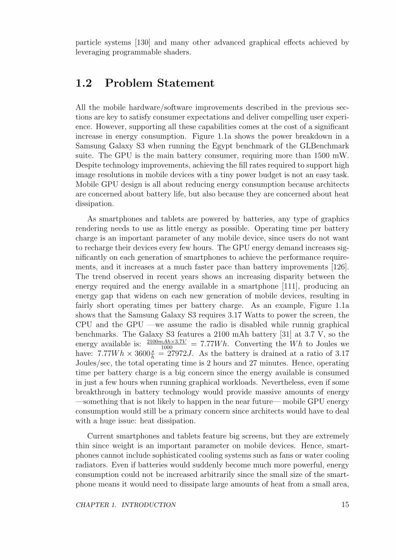
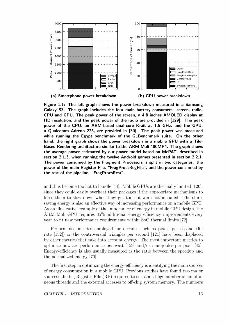
All the mobile hardware/software improvements described in the previous sec-tions are key to satisfy consumer expectations and deliver compelling user experi-ence. However, supporting all these capabilities comes at the cost of a significantincrease in energy consumption. Figure 1.1a shows the power breakdown in aSamsung Galaxy S3 when running the Egypt benchmark of the GLBenchmarksuite. The GPU is the main battery consumer, requiring more than 1500 mW.Despite technology improvements, achieving the fill rates required to support highimage resolutions in mobile devices with a tiny power budget is not an easy task.Mobile GPU design is all about reducing energy consumption because architectsare concerned about battery life, but also because they are concerned about heatdissipation.
As smartphones and tablets are powered by batteries, any type of graphicsrendering needs to use as little energy as possible. Operating time per batterycharge is an important parameter of any mobile device, since users do not wantto recharge their devices every few hours. The GPU energy demand increases sig-nificantly on each generation of smartphones to achieve the performance require-ments, and it increases at a much faster pace than battery improvements [126].The trend observed in recent years shows an increasing disparity between theenergy required and the energy available in a smartphone [111], producing anenergy gap that widens on each new generation of mobile devices, resulting infairly short operating times per battery charge. As an example, Figure 1.1ashows that the Samsung Galaxy S3 requires 3.17 Watts to power the screen, theCPU and the GPU —we assume the radio is disabled while runnig graphicalbenchmarks. The Galaxy S3 features a 2100 mAh battery [31] at 3.7 V, so theenergy available is: 2100mAh×3.7V
1000= 7.77Wh. Converting the Wh to Joules we
have: 7.77Wh × 3600 sh
= 27972J . As the battery is drained at a ratio of 3.17Joules/sec, the total operating time is 2 hours and 27 minutes. Hence, operatingtime per battery charge is a big concern since the energy available is consumedin just a few hours when running graphical workloads. Nevertheless, even if somebreakthrough in battery technology would provide massive amounts of energy—something that is not likely to happen in the near future— mobile GPU energyconsumption would still be a primary concern since architects would have to dealwith a huge issue: heat dissipation.
Current smartphones and tablets feature big screens, but they are extremelythin since weight is an important parameter on mobile devices. Hence, smart-phones cannot include sophisticated cooling systems such as fans or water coolingradiators. Even if batteries would suddenly become much more powerful, energyconsumption could not be increased arbitrarily since the small size of the smart-phone means it would need to dissipate large amounts of heat from a small area,
CHAPTER 1. INTRODUCTION 15
0
500
1000
1500
2000
2500
3000
3500
4000
Peak
Sus
tain
ed P
ower
(mW
)
ScreenRadioCPUGPU
(a) Smartphone power breakdown
0
20
40
60
80
100
Perc
enta
ge o
f Pow
er (%
)
OtherFragProcsRestFragProcsRegFileVertexProcsL2SystemMemory
(b) GPU power breakdown
Figure 1.1: The left graph shows the power breakdown measured in a SamsungGalaxy S3. The graph includes the four main battery consumers: screen, radio,CPU and GPU. The peak power of the screen, a 4.8 inches AMOLED display atHD resolution, and the peak power of the radio are provided in [129]. The peakpower of the CPU, an ARM-based dual-core Krait at 1.5 GHz, and the GPU,a Qualcomm Adreno 225, are provided in [30]. The peak power was measuredwhile running the Egypt benchmark of the GLBenchmark suite. On the otherhand, the right graph shows the power breakdown in a mobile GPU with a Tile-Based Rendering architecture similar to the ARM Mali 400MP4. The graph showsthe average power estimated by our power model based on McPAT, described insection 2.1.3, when running the twelve Android games presented in section 2.2.1.The power consumed by the Fragment Processors is split in two categories: thepower of the main Register File, “FragProcsRegFile”, and the power consumed bythe rest of the pipeline, “FragProcsRest”.
and thus become too hot to handle [44]. Mobile GPUs are thermally limited [120],since they could easily overheat their packages if the appropriate mechanisms toforce them to slow down when they get too hot were not included. Therefore,saving energy is also an effective way of increasing performance on a mobile GPU.As an illustrative example of the importance of energy in mobile GPU design, theARM Mali GPU requires 35% additional energy efficiency improvements everyyear to fit new performance requirements within SoC thermal limits [72].
Performance metrics employed for decades such as pixels per second (fillrate [152]) or the controversial triangles per second [121] have been displacedby other metrics that take into account energy. The most important metrics tooptimize now are performance per watt [159] and/or nanojoules per pixel [45].Energy-efficiency is also usually measured as the ratio between the speedup andthe normalized energy [70].
The first step in optimizing the energy-efficiency is identifying the main sourcesof energy consumption in a mobile GPU. Previous studies have found two majorsources: the big Register File (RF) required to sustain a huge number of simulta-neous threads and the external accesses to off-chip system memory. The numbers
CHAPTER 1. INTRODUCTION 16
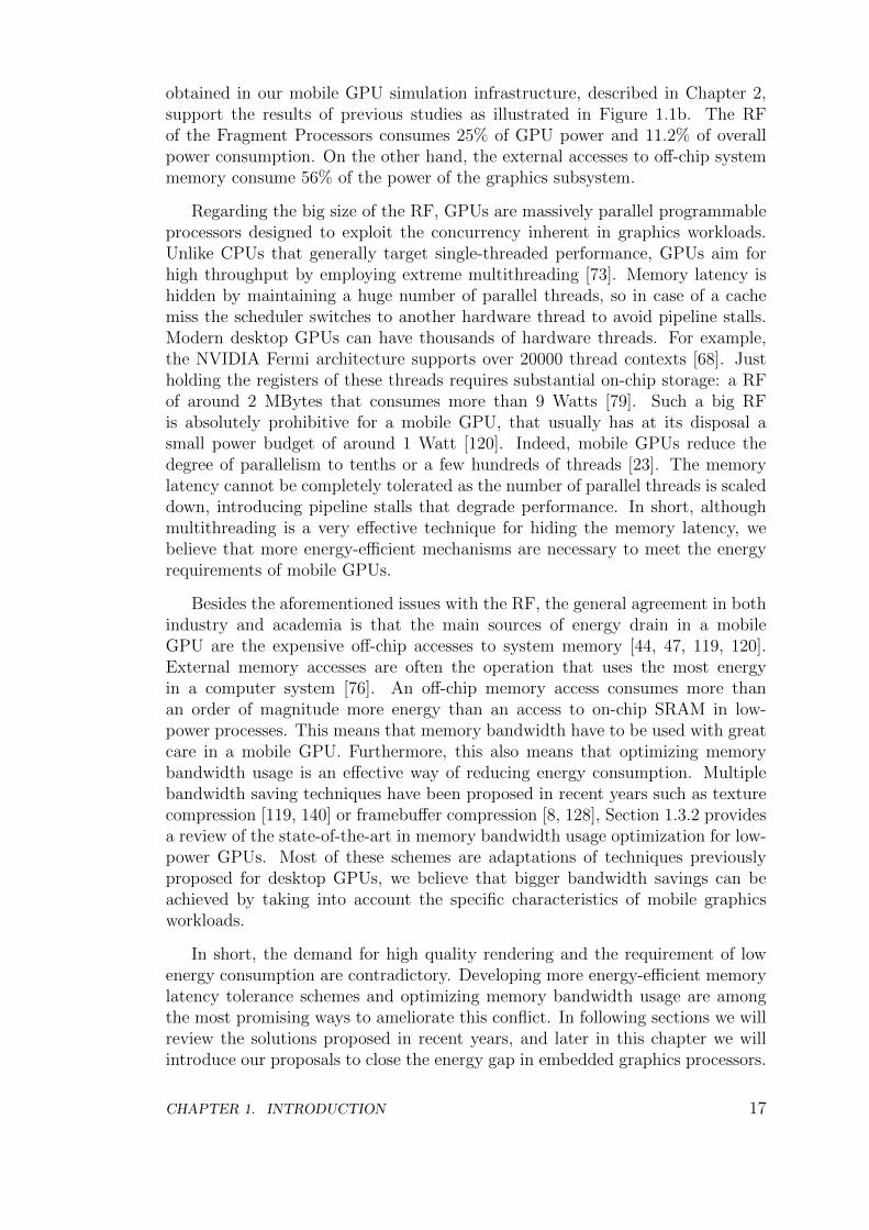
obtained in our mobile GPU simulation infrastructure, described in Chapter 2,support the results of previous studies as illustrated in Figure 1.1b. The RFof the Fragment Processors consumes 25% of GPU power and 11.2% of overallpower consumption. On the other hand, the external accesses to off-chip systemmemory consume 56% of the power of the graphics subsystem.
Regarding the big size of the RF, GPUs are massively parallel programmableprocessors designed to exploit the concurrency inherent in graphics workloads.Unlike CPUs that generally target single-threaded performance, GPUs aim forhigh throughput by employing extreme multithreading [73]. Memory latency ishidden by maintaining a huge number of parallel threads, so in case of a cachemiss the scheduler switches to another hardware thread to avoid pipeline stalls.Modern desktop GPUs can have thousands of hardware threads. For example,the NVIDIA Fermi architecture supports over 20000 thread contexts [68]. Justholding the registers of these threads requires substantial on-chip storage: a RFof around 2 MBytes that consumes more than 9 Watts [79]. Such a big RFis absolutely prohibitive for a mobile GPU, that usually has at its disposal asmall power budget of around 1 Watt [120]. Indeed, mobile GPUs reduce thedegree of parallelism to tenths or a few hundreds of threads [23]. The memorylatency cannot be completely tolerated as the number of parallel threads is scaleddown, introducing pipeline stalls that degrade performance. In short, althoughmultithreading is a very effective technique for hiding the memory latency, webelieve that more energy-efficient mechanisms are necessary to meet the energyrequirements of mobile GPUs.
Besides the aforementioned issues with the RF, the general agreement in bothindustry and academia is that the main sources of energy drain in a mobileGPU are the expensive off-chip accesses to system memory [44, 47, 119, 120].External memory accesses are often the operation that uses the most energyin a computer system [76]. An off-chip memory access consumes more thanan order of magnitude more energy than an access to on-chip SRAM in low-power processes. This means that memory bandwidth have to be used with greatcare in a mobile GPU. Furthermore, this also means that optimizing memorybandwidth usage is an effective way of reducing energy consumption. Multiplebandwidth saving techniques have been proposed in recent years such as texturecompression [119, 140] or framebuffer compression [8, 128], Section 1.3.2 providesa review of the state-of-the-art in memory bandwidth usage optimization for low-power GPUs. Most of these schemes are adaptations of techniques previouslyproposed for desktop GPUs, we believe that bigger bandwidth savings can beachieved by taking into account the specific characteristics of mobile graphicsworkloads.
In short, the demand for high quality rendering and the requirement of lowenergy consumption are contradictory. Developing more energy-efficient memorylatency tolerance schemes and optimizing memory bandwidth usage are amongthe most promising ways to ameliorate this conflict. In following sections we willreview the solutions proposed in recent years, and later in this chapter we willintroduce our proposals to close the energy gap in embedded graphics processors.
CHAPTER 1. INTRODUCTION 17

1.3 State-of-the-art in GPU Energy Efficiency
Improving the energy-efficiency of mobile GPUs has attracted a lot of attentionfrom the architecture community in recent years. As stated in prior section,reducing the energy consumption of the RF is one of the primary concerns re-garding mobile GPU design, previous studies have focused on saving RF energyas described in Section 1.3.1. On the other hand, saving memory bandwidth hasbeen proven to be an effective way of reducing energy consumption and, hence,multiple techniques targeting memory bandwidth usage optimization have beenproposed as depicted in Section 1.3.2.
1.3.1 Memory Latency Tolerance Techniques
Graphics workloads have a large amount of inherent parallelism that can be easilyexploited by a parallel machine. Texture memory accesses are common operationsin graphics workloads and tend to be fine-grained and difficult to prefetch [79].Graphics workloads have large, long-term (inter-frame) working sets that are notamenable to caching. Therefore, texture cache units focus on conserving band-width rather than reducing latency [73]. Because texture accesses are macro-scopically unpredictable, and frequent, GPUs rely on massive multithreading tokeep arithmetic units utilized. As a result, a huge RF is required to maintain theregisters of all the simultaneous threads.
In this section we will first review previous work focused on optimizing theenergy consumption of the GPU RF. Second, we will discuss other research workbased on the use of prefetching to hide the memory latency, with the objectiveof reducing the multithreading degree requirements and, hence, the size and theenergy consumption of the RF. Finally, we will review related work on DecoupledAccess/Execute architectures.
Register File Optimizations
Gebhart et al. [79] propose the use of a Register File Cache to replace accessesto the large main RF with accesses to a smaller structure containing the immedi-ate register working set of active threads. As extreme multithreading requires acomplicated thread scheduler, the authors also propose a two-level thread sched-uler that maintains a small set of active threads to hide ALU and local memoryaccesses, and a larger set of pending threads to hide main memory latency. Com-bined with the RF Cache, this two-level thread scheduler provides a further re-duction in energy by limiting the allocation of temporary register cache resourcesto only the currently active subset of threads. The authors report significantenergy savings in both graphics and GPGPU workloads. Note that this approachsaves dynamic energy by replacing accesses to a bigger hardware structure byaccesses to a smaller structure, but it does not save static energy as the originalbig RF is kept as in conventional GPUs.
CHAPTER 1. INTRODUCTION 18
Yu et al. [169] introduce a hybrid memory design that tightly integrates em-bedded DRAM into SRAM cells to reduce area and energy consumption of amulti-threaded RF. In this memory, each SRAM cell is augmented with multipleDRAM cells so that multiple bits can be stored in each cell. This approach savesboth dynamic energy and leakage by keeping data for active threads in SRAMwhile placing data for pending threads in DRAM. However, such a RF requiresexplicit data movements between SRAM and DRAM in order to access the reg-isters of pending threads. The thread scheduler has to be modified in order tominimize context switching impact.
Regarding proposals that specifically target mobile GPUs, Sohn et al. [167]propose a mechanism for clock gating an entire RF bank when it is not beingaccessed. Chu et al. [63] introduce the possibility of further reducing dynamicenergy by dividing the register bank into multiple regions and controlling clockgating individually. In a later study, Chu et al [89] extended their work proposingan Adaptive Thread Scheduling mechanism combined with a low-power RF withhybrid power gating [103]. Besides dynamic energy savings, this RF exploits bothgated-Vdd and drowsy techniques [75] to achieve long and short term leakage en-ergy savings. Finally, a compiler-assisted demand-driven RF for mobile GPUs ispresented in [90]. In this scheme the RF is shared on demand between concurrentthreads, and multiple power gating modes are employed to avoid wasting staticenergy for unused registers.
Prefetching
Besides multithreading, prefetching data into the caches can also help toleratememory latency. The largest concerns with any prefetching scheme are accuracyand timeliness. Regarding accuracy, if an application’s memory stream is irregu-lar or unpredictable cache pollution can occur and increase the number of cacheaccesses and, hence, energy consumption. Regarding timeliness, prefetch requestshave to be issued at the appropriate time in order to be effective. Otherwise datacould be prefetched too early and evicted before accessed from the application,or prefetched too late so the memory latency cannot be completely tolerated.Note that prefetching can only provide memory latency tolerance, whereas mul-tithreading can hide both memory and functional units latency.
Several hardware-based data prefetching schemes for CPUs have been pro-posed in past decades. The next-line [58] and the stride [77] prefetchers are com-monly implemented in desktop CPUs as they perform well for typical CPU work-loads and they require simple hardware. More sophisticated prefetching schemestry to correlate recent miss addresses, such as the Markov prefetcher [100], whereasother prefetchers try to correlate recent strides, like the distance prefetcher [102].On the other hand, Nesbit et al. [114] show that the history information employedby the previous prefetchers, that is typically stored in a table, can be kept moreefficiently in a new hardware structure called the Global History Buffer.
Classical CPU prefetching results in higher performance, but worse energy insome cases due to unnecessary data being fetched on chip. With the advent of
CHAPTER 1. INTRODUCTION 19
General Purpose computing on GPUs (GPGPU), several authors have proposedto use prefetching in GPUs with the main objective of saving energy. Sethia etal. [135] proposed APOGEE, a prefetching mechanism able to dynamically detectand adapt to the memory access patterns found in scientific codes that are runon modern GPUs. APOGEE employs multi-thread miss address stream analysis,instead of considering threads in isolation, to improve accuracy and timeliness inhighly threaded processors. The net effect is that fewer threads are required totolerate memory latency and thus sustain performance. Hence, APOGEE savesenergy by removing part of the thread contexts in the big and complex RF of aGPU, and including instead the smaller and simpler prefetch tables.
Lee et al. [106] also proposed the use of hardware prefetching for GPGPUapplications. They show that conventional CPU prefetchers cannot be straight-forwardly applied to GPGPU systems. Instead, they propose a stride basedprefetcher tailored to many-core architectures. This prefetcher is based on inter-thread prefetching mechanisms and an adaptive throttling scheme to disableprefetching when it is useless, significantly improving accuracy and reducing en-ergy waste.
The prefetchers previously mentioned target general purpose applications run-ning on CPUs or GPGPU systems. That is why they do not take into accountthe specific issues with graphics workloads and the ubiquitous and unpredictabletexture fetches. Igehy et al. [93] proposed a prefetching architecture for texturecaches that is designed to accelerate the process of applying textures on triangles.This texture prefetcher is thoroughly discussed in Chapter 3.
Decoupled Access/Execute
A Decoupled Access/Execute architecture [138] divides the program into twoindependent instruction streams, one doing memory accesses and the other per-forming computations. By decoupling memory accesses from computations, ac-cess/execute architectures effectively prefetch data from memory much in advancefrom the time it is required, thus allowing cache miss latency to overlap with use-ful computations without causing stalls. While this can be viewed as a form ofdata prefetching, it has a substantial advantage over other prefetching schemes,because it relies on computed rather than predicted addresses, which translatesinto a higher accuracy and a lower energy waste.
Despite the high potential of access/execute architectures to tolerate a longmemory latency at a moderate hardware cost, they have not been widely adoptedby current commercial CPUs because their effectiveness is greatly degraded whenthe computation of an address has a data or control dependence on the executionstream (this occurs, for instance, in pointer chasing codes). In such circumstances,termed loss of decoupling events (LOD), the access stream is forced to stall inorder to synchronize with the execution stream. LODs force the access stream tolose its timeliness (i.e. the prefetch distance), so that subsequent cache misses willcause the execution stream to stall as well. Unfortunately, for general purpose
CHAPTER 1. INTRODUCTION 20
CPUs the frequency of LODs is quite significant in many cases, resulting in fairlyrestricted performance gains.
Crago et al. [71, 70] propose the use of Decoupled Access/Execute architec-tures to hide the memory latency in highly threaded workloads. Their schemeis different from classical access/execute architectures as they run the multipleinstruction streams in just one core by using multiple thread contexts, insteadof having two separate processors for memory accesses and computations. Fur-thermore, they propose several strategies to mitigate the effect of LODs in mul-tithreaded applications. Overall, they show that decoupled access/execute is aneffective energy saving technique in many-core architectures as it requires simplehardware and, in addition, the number of thread contexts required to keep thefunctional units busy can be significantly reduced. It is worth noting that simi-lar conclusions about the synergy of decoupling and multithreading were alreadysuggested in [122].
Talla et al. [141, 142] describe the benefits of Decoupled Access/Execute formultimedia applications. They introduce the MediaBreeze architecture, a sys-tem that decouples the useful/true computations from the overhead/supportinginstructions that are necessary to feed the SIMD execution units. The Media-Brezze architecture includes hardware for efficient address generation, loopingand data reorganization. The proposal was evaluated on top of an out-of-orderCPU with SIMD extensions and the authors reported significant performanceimprovements in media applications.
1.3.2 Bandwidth Saving Techniques
The rendering of 3D computer graphics requires the GPU to fetch big datasetsfrom main memory on a frame basis. Retrieving these massive amounts of datais one of the main sources of energy consumption on a mobile GPU and thusoptimizing memory bandwidth usage is a primary concern in embedded graphicsprocessors. In this section we will review previous techniques to reduce the num-ber of external memory accesses to the texture datasets and to the framebuffers.
Tile-Based Rendering
Desktop GPUs implement an Immediate-Mode Rendering (IMR) architecture [113].In IMR, the geometry that describes an object is transformed in the vertex proces-sors and immediately sent down the graphics pipeline for further pixel processing,updating the framebuffer before processing the next object. If a subsequent ob-ject is rendered on top of a previous one, the colors of the pixels are computedagain and overwritten in the framebuffer. This issue is commonly known as theoverdraw problem [56]: the colors of some pixels are computed and written mul-tiple times into main memory due to multiple graphical objects being drawn overthe top of one another, resulting in a waste of bandwidth. The average num-ber of times a pixel is written in a single frame is often referred as the depthcomplexity [69].
CHAPTER 1. INTRODUCTION 21
Tile-Based Rendering (TBR) architectures [44] are designed to address theoverdraw. In TBR the screen is split into rectangular blocks of pixels calledtiles, and the frames are generated tile by tile. Tiles are small enough so theportion of the framebuffer corresponding to a tile can be stored in local on-chipmemory, avoiding off-chip accesses to a large extent. Unlike IMR architectures,transformed 2D triangles are not immediately rendered in the framebuffer, insteadthey are stored into main memory in the Scene buffer [51]. Furthermore, 2Dtriangles are sorted into tiles, so for each tile a triangle overlaps a pointer to thattriangle is stored. Once all the geometry for a given frame has been transformedand sorted, the rendering starts tile by tile. Note that pixels are written justonce in main memory, as the tiles are generated first in the local on-chip memoryand copied to the corresponding region of the framebuffer only when they areready, i. e. when all the triangles for the given tile have been rendered. TBRprovides significant bandwidth savings for generating the framebuffer, however, itrequires the 2D triangles to be stored in memory and fetched back for rendering,so it trades geometry bandwidth for pixel bandwidth. Antochi et al [52] reportsignificant bandwidth savings in low-power systems by using TBR. AlthoughIMR dominates the desktop GPU segment, TBR is more popular in the mobilesegment [9, 161, 162] as the geometry datasets of mobile workloads are smallerand, hence, the extra cost of storing/fetching 2D geometry is usually less thanthe bandwidth savings in the framebuffers.
Compression
Compression techniques can reduce both the memory footprint and the band-width requirements of graphical workloads. In first place, hardware texture com-pression was introduced by Knittel et al. [105] and Beers et al. [60]. The core ideais to use lossy compression on the textures, and store the compressed version insystem memory. When accessing the texture during rendering, the compressedtexture is transferred over the bus, and decompressed on-the-fly as needed, thussaving bandwidth.
Strom et al [140] propose iPackman, a texture compression scheme that tar-gets mobile devices. iPackman has low-complexity, being amenable for hardwareimplementation on embedded graphics processors. Furthermore, it achieves highimage fidelity and compression ratios of 4 bits per pixel (bpp). The OpenGL ES3.0 API introduces support for texture compression by using the Ericsson TextureCompression [151] (ETC2/EAC version) algorithm, which is based on iPackman.
On the other hand, the major mobile GPU manufacturers provide their vendor-specific texture compression methods. ARM Mali supports the Adaptive ScalableTexture Compression (ASTC) [119], a lossy compression algorithm that providesa high degree of flexibility to trade image quality for bandwidth savings. ASTCachieves bit rates ranging from 8 bpp to less than 1 bpp in very fine steps. Qual-comm Adreno also supports texture compression by using the ATC [1] algorithm,whereas Imagination PowerVR leverages PVRTC [74] and NVIDIA Tegra pro-vides support for DXT compression [109, 123].
CHAPTER 1. INTRODUCTION 22
Besides texture compression, framebuffer compression can also provide signif-icant bandwidth savings. The framebuffer consists of a set of 2D buffers requiredfor rendering such as the color buffer, that stores a RGBA color for each pixel inthe screen, or the depth buffer, that keeps a depth value for each pixel in order tosolve visibility. Framebuffer compression works in a similar way than texture com-pression does, storing the buffers compressed in main memory, transferring thedata compressed over the bus, decompressing on-the-fly when reading and com-pressing on-the-fly when writing to the framebuffer. Note that the color bufferhas to be uncompressed in order to be displayed on the screen, in case of usingframebuffer compression the display controller has to include the correspondingcolor buffer decompression hardware.
Regarding IMR GPU architectures, Rasmusson et al. [128] propose both loss-less and lossy compression algorithms for the color buffer. Hasselgren et al. [86]introduce a depth buffer compression algorithm to save bandwidth in the depthtest. Regarding TBR architectures, ARM Frame Buffer Compression (AFBC) in-troduces the compression of the tiles before being transferred from local on-chipmemory to system memory, achieving compression ratios of 50% with a losslessalgorithm. As for the depth buffer, Tile-Based architectures do not usually re-quire to save and restore the depth values of the tiles. In OpenGL ES 2.0 thedriver can infer in some cases that the contents of the depth buffer does not needto be preserved from frame to frame, whereas OpenGL ES 3.0 introduces the glIn-validateFramebuffer [80] function call to explicitly indicate to the driver that thedepth buffer is not required to be saved/restored. Hence, TBR architectures cancompletely avoid all the transfers to the external depth buffer in main memory.
Transaction Elimination
Transaction Elimination [57, 120] (TE) is a bandwidth saving technique for Tile-Based GPU architectures introduced by ARM and implemented in the MaliGPUs. With TE, the graphics hardware compares the current framebuffer withthe previously rendered frame and performs a partial update only to the particu-lar parts of it that have been modified, thus significantly reducing the amount ofdata transferred per frame to external memory. The comparison is done on a pertile basis, using a Cyclic Redundancy Check signature to determine if the tile hasbeen modified. Tiles with the same signature are identical and eliminating themhas no impact in the resulting image quality. TE is highly effective for populargraphical applications such as User Interfaces or casual games, since they usuallyfeature static 2D backgrounds and there are not many changes from frame toframe. However, it is also effective for other graphical applications like 3D gamesor video.
Multi-View and Multi-Frame Rendering
Stereoscopic and 3D displays require the generation of multiple views or images forevery single frame. Hasselgren et al. [87] propose a novel rasterization architecture
CHAPTER 1. INTRODUCTION 23
that renders each triangle to multiple views simultaneously, with the objective ofmaximizing the hit rate in the texture caches and thus saving memory bandwidth.When determining which view to rasterize next, the architecture employs anefficiency metric that estimates which view is expected to get the most hits in thetexture cache. As the different views of the same frame are very similar, a betterutilization of the texture caches is achieved by generating the multiple imagesin parallel instead of rendering the views sequentially. Instead of processing allthe triangles for a given view and then proceed to the next one, the proposedarchitecture iterates all the views for each triangle to maximize texture locality.
NVIDIA Scalable Link Interface (SLI) [118] is a multi-GPU configuration thatoffers increased rendering performance by dividing the workload across multipleGPUs. The most common SLI configuration is known as Alternate Frame Ren-dering (AFR). Under AFR the driver divides the workload by alternating GPUsevery frame. For example, on a system with two SLI-enabled GPUs, odd frameswould be rendered by GPU 1 whereas even frames would be rendered by GPU2. The main target of AFR is to increase graphics performance by duplicatinghardware resources and increasing memory bandwidth, so power consumption isalso significantly increased. However, it is possible to save bandwidth and energyin a multi-GPU system if the multiple graphics processors share a single memoryaddress space as suggested in [112], in that case part of the dataset employed forrendering can be shared by the different GPUs.
1.3.3 Other Related Works
Mochocki et al [111] propose the use of Dynamic Voltage and Frequency Scaling(DVFS) in mobile 3D graphics pipelines. Want et al. [147, 148] describe differentpower gating strategies for graphics processors. Chu et al [61, 62, 88] proposedynamic precision selection in the GPU shader cores, switching at runtime be-tween fixed-point arithmetic —faster and more energy-efficient— and floating-point arithmetic —better graphics quality.
As described in previous sections, the overdraw [56] is one of the main issuesin graphics processors as it results in a waste of bandwidth and energy. Hence,different hardware-based techniques that try to address the overdraw in mobileGPUs have been proposed. The ULP GeForce GPU in the NVIDIA Tegra SoCfeatures Early-Z rejection [115] to preemptly discard fragments that are knownto be occluded. When using Early-Z rejection, the depth test is performed beforethe execution of the fragment shader to avoid computing the colors of non-visiblefragments. This scheme achieves maximum efficiency when the triangles are sentto the GPU ordered from front to back. On the contrary, worst case happenswhen triangles are sent ordered from back to front, as younger fragments alwaysoverlap older fragments and, hence, they always pass the depth test and proceedto the fragment shader.
Tile-Based architectures are designed to minimize the impact of the overdrawsince pixels are written just once into off-chip system memory due to the use of
CHAPTER 1. INTRODUCTION 24
local on-chip color buffers. However, the colors of some pixels are still computedand written multiple times in the local on-chip memory. Ideally, the fragmentshader should be executed just once for each screen pixel on every frame to com-pletely remove the overdraw 1. Some mobile GPUs include techniques to removere-executions of the fragment shader for the same screen pixel, in order to avoidspending time and energy in shading fragments that are not going to contributeto the final image. For example, ARM Mali GPUs implement Forward Pixel Kill(FPK) [21]. In an FPK-enabled GPU, the threads that shade fragments are notirrevocably committed to complete once they are launched. On the contrary, in-flight threads can be terminated at any time if the hardware detects that a laterthread will write opaque data to the same pixel location. On the other hand,Imagination Technologies PowerVR GPUs include hardware for Hidden SurfaceRemoval (HSR) [28]. With HSR all the geometry for a tile is processed and thevisibility is completely solved before shading any fragment. Once the closest-to-the-observer fragment for each pixel in the tile has been found the fragmentshader computations take place and, hence, each pixel is shaded just once.
1.4 Thesis Overview and Contributions
The goal of this thesis is to propose novel and effective techniques that addressthe issues in mobile GPU design, with the objective of improving the energy-efficiency of embedded graphics processors while keeping complexity low. Ourmain contributions are a decoupled access/execute-like architecture for the Frag-ment Processors, a bandwidth saving technique called Parallel Frame Renderingand a hardware-based memoization scheme that avoids redundant computationsand memory accesses. All these proposals apply to a conventional mobile GPUarchitecture, and can be implemented on top of both Immediate-Mode and Tile-Based GPUs. The following sections outline the problems we are trying to solve,describe the approach we take to solve the problem and provide a comparisonwith related work, highlighting the novel contributions of this thesis.
1.4.1 Mobile GPU Simulation Infrastructure
We have developed our custom mobile GPU simulation infrastructure, that we callTEAPOT. To the best of our knowledge, TEAPOT is the first simulator tailoredtowards the mobile segment, as none of the previous GPU simulators providesupport for running Android graphical applications that employ the OpenGL ESAPI. TEAPOT consists on a set of tools for evaluating the performance, energyconsumption and image quality of mobile graphics processors. Its main target isto drive the evaluation of energy saving techniques for mobile GPUs.
Regarding its features, TEAPOT provides full-system simulation of Androidapplications. Furthermore, it includes a GPU timing simulator able to model
1In case transparent or translucent objects are included in the scene the optimum numberof executions of the fragment shader can be greater than one per pixel
CHAPTER 1. INTRODUCTION 25
both Tile-Based and Immediate-Mode rendering architectures, a power model formobile GPUs, and automatic image quality assessment by using several metrics.TEAPOT is extensively described in Chapter 2. This infrastructure was presentedin a paper published in the proceedings of the 27th International Conference onSupercomputing:
• “TEAPOT: A Toolset for Evaluating Performance, Power and Image Qual-ity on Mobile Graphics Systems”.Jose-Maria Arnau, Joan-Manuel Parcerisa and Polychronis Xekalakis.International Conference on Supercomputing, 2013.
The development of tools for evaluating the GPU has attracted the attentionof the architectural community the last few years. Recent simulators, such asGPGPUSim [59] or Barra [65], model General Purpose GPU (GPGPU) architec-tures. These tools support CUDA [116] or OpenCL [172], but they do not sup-port graphics APIs such as OpenGL [97]. GPGPUSim includes a power model,GPUWattch [170], which is also based on McPAT as in TEAPOT. Both powermodels are similar, but GPUWattch focuses on GPGPU specific features whereasTEAPOT models more specialized graphics hardware. For instance, GPGPUSimmodels FP units that can be combined to execute 1 double-precision (DP) or 2single-precision (SP) operations, but TEAPOT relies on SP units since DP iscommon in scientific workloads but not in games. On the contrary, TEAPOTmodels specialized Texture Sampling units since texture fetching instructions arefrequent in graphical workloads.
ATTILA [113] provides an OpenGL framework for collecting traces of desk-top games and a cycle-accurate GPU simulator. A Direct3D [171] driver is alsoincluded in the last versions. Although ATTILA provides full support for desk-top games, it cannot run applications for smartphones. Furthermore, its GPUsimulator models a desktop-like Immediate-Mode Renderer, whereas Tile-BasedRendering is much more popular in smartphones. Finally, ATTILA does not in-clude a power model. Qsilver [136] can also collect traces from desktop OpenGLgames and it models a desktop-like NVIDIA GPU, including a power model.GRAAL [101] also provides OpenGL support and a power model for GPUs. Fur-thermore, it models a low-power Tile-Based Rendering architecture. However,OpenGL ES support is not available in any of these simulators so they cannotrun mobile applications for smartphones and tablets. Unlike the aforementionedtools, TEAPOT provides image quality metrics for automatic image quality as-sessment. In addition, TEAPOT supports full-system GPU simulation, beingable to profile multiple applications accessing the GPU concurrently.
1.4.2 The Decoupled Access/Execute Fragment Processor
Extreme multithreading is the solution employed by desktop GPUs to hide thememory latency, as both graphical and GPGPU workloads exhibit a high de-gree of parallelism. However, aggressive multithreading requires a huge Register
CHAPTER 1. INTRODUCTION 26
File (RF) to keep the registers of all the parallel threads. Bound by severe en-ergy constraints, mobile GPUs cannot accommodate such a big RF in their tinypower budgets. Hence, memory latency cannot be completely tolerated just byusing multithreading due to the smaller number of parallel threads employed inembedded graphics processors.
In first place we evaluate the effects of aggressive multithreading in a mo-bile GPU, analyzing its impact on performance and energy consumption. Asthe results show that multithreading is effective but not energy-efficient, due tothe big size of the RF, we try to reduce the number of hardware threads bycombining multithreading with other memory latency tolerance techniques suchas prefetching. We evaluate several state-of-the-art CPU, GPU and GPGPUhardware prefetchers on a mobile GPU running graphics workloads. The resultsobtained in our cycle-accurate timing simulator indicate that these prefetchers ob-tain non-negligible performance improvements, but they perform far from idealas texture accesses are highly unpredictable.
In second place, we propose a decoupled access/execute-like architecture forthe fragment processors of a mobile GPU. For GPU fragment programs the mem-ory access patterns are typically free of the dependences that cause Loss of De-coupling (LOD) events. This makes the access/execute paradigm a perfect fit forthe requirements of a low-power high-performance GPU: with few extra hard-ware requirements it can reduce drastically the number of cache miss stalls. Inour scheme, all the necessary data for processing the fragments is prefetched intothe caches while the fragments are waiting to be dispatched to the GPU cores.By the time a fragment is issued all the data required to process the fragmentis hopefully available in the caches, significantly improving the hit rates in theshader cores.
In third place, we improve our base system by introducing remote L1 cacheaccesses to exploit the high degree of data sharing among fragment processors.When the system detects that a cache line that is going to be prefetched in the L1cache of a fragment processor has been recently prefetched in another L1 cache,the memory request is redirected to this cache instead of accessing the bigger L2cache. This optimization saves bandwidth to the L2 cache and saves additionalenergy by replacing accesses to the bigger L2 cache by accesses to the smallerL1 caches. The end design is able to achieve similar performance to a heavily-threaded GPU by consuming only a fraction of its energy. More specifically, weevaluate our scheme on top of a state-of-the-art mobile GPU by using severalcommercial Android games, and show that the end design is able to achieve 97%of the performance of a massively multithreaded GPU, while providing 20.5%energy savings. This work has been published in the proceedings of the 39thInternational Symposium on Computer Architecture (ISCA):
• “Boosting Mobile GPU Performance with a Decoupled Access/ExecuteFragment Processor”.Jose-Maria Arnau, Joan-Manuel Parcerisa and Polychronis Xekalakis.International Symposium on Computer Architecture, 2012.
CHAPTER 1. INTRODUCTION 27
Unlike most of the prefetching schemes described in section 1.3.1, our work isfocused on graphics workloads instead of general purpose applications. Further-more, our scheme employs computed addresses rather than predicted addressesto significantly improve accuracy, as in graphics workloads the memory accesspatterns are typically free of dependences. The work that is closest to ours is theprefetching architecture for texture caches proposed by Igehy et al. [93]. How-ever, our work is different in several ways. First, our system is built on top of amodern mobile GPU pipeline instead of a fixed-function pipeline, so our schemesupports multicore GPUs, programmable shaders and multiple texture fetchesper fragment. Second, we take advantage of the Early-Z Test to only prefetchdata for visible fragments, increasing the energy efficiency. Third, our proposalallows for remote L1 requests to exploit the high degree of data sharing amongfragment processors, providing significant energy benefits.
The efforts to reduce register file power on a GPU include the register filecache and the two-level warp scheduler proposed by Gebhart et al. [79], and thehybrid SRAM-DRAM memory design presented by Yu et al. [169]. We showthat there is no real necessity for high degree of multithreading and as suchfor large register files, as multithreading can be combined with other techniquesto hide the memory latency in a more energy-efficient way. On the other hand,the abovementioned research is focused on GPGPU workloads, whereas our studytargets graphical applications. General purpose codes employ complex addressingmodes that can cause loss of decoupling events, reducing the effectiveness ofdecoupled access/execute architectures. However we believe that mobile phonesare not the ideal platform for scientific applications, so our research is focused onmore typical workloads for smartphones, such as games.
Recently, research in the field of mobile GPUs has emerged. Akenine-Mollerand Strom [47] propose a rasterization architecture for mobile devices that em-ploys a novel texture compression system to reduce memory bandwidth usage by53%. Our work is also focused on reducing bandwidth, but we achieve bandwidthsavings by exploiting inter-core data sharing.
Tarjan et al. [143] propose the sharing tracker, a simplified directory employedto capture inter-core reusage among the private non-coherent caches of a GPU.Our decoupled system is also able to exploit data sharing, but at a smaller energycost by using a much smaller hardware structure, the prefetch queue. On the otherhand, several tiled-cache approaches have been proposed. Reactive NUCA [85] in-troduces fixed-center clusters and rotational interleaving on a distributed sharedL2 cache, these novel mechanisms provide high aggregate capacity while exploit-ing fast nearest-neighbour communication. NoC-aware cache design [43] intro-duces a first-touch data placement policy, a migration policy that moves eachblock to its most frequent sharer and a replacement policy that is biased towardsretaining shared blocks and replacing private ones. DAPSCO [78] consists on adistance-aware cache organization that minimizes the average distance travelledby cache requests. In our system the L2 cache is centralized instead of distributed,since the number of cores in a mobile GPU is much smaller than what is assumedin a many-core system due to power constraints. Furthermore, the tiled-cached
CHAPTER 1. INTRODUCTION 28
systems use the hardware coherence mechanisms (directory) to detect data shar-ing among the first level caches, whereas we employ the prefetch queue to detectdata reusage among non-coherent L1 caches at a much smaller energy budget(hardware coherent caches are considered too expensive for GPUs [143]).
Crago et al. [71] present OUTRIDER, a decoupled system for throughput-oriented processors. OUTRIDER is similar to our proposal since it also employsa decoupled access/execute architecture to hide the memory latency with fewerthreads. However, our system reduces hardware complexity, does not requirecompiler assistance to generate the instruction streams and it is able to detectinter-core data sharing. On the other hand, OUTRIDER offers better tolerance toLODs by using multiple memory access streams, so it is best suited for scientificapplications whereas our system is best suited for graphical workloads.
1.4.3 Parallel Frame Rendering
A large fraction of a mobile GPU energy consumption can be attributed to theexternal off-chip memory accesses to system RAM. As noted by [87, 119], most ofthese accesses fetch textures. Our numbers support this claim, as we found that62% of the memory accesses can be directly attributed to texture data on averagein our set of commercial Android workloads. Focusing on the texture dataset ofconsecutive frames, we realized that there exists a large degree of reuse acrossframes. Hence, the same textures are fetched frame after frame, but the GPUcannot exploit these frame-to-frame reuses due to the huge size of the texturedataset.
Firstly, we present Parallel Frame Rendering (PFR), a technique to improvetexture locality on a mobile GPU. Under PFR, two consecutive frames are pro-cessed in parallel by devoting half of the graphics hardware resources to rendereach frame. By using this organization, each texture is read from memory onceand used for rendering two successive frames. Therefore, textures are fetchedfrom memory just once every two frames instead of being fetched on a framebasis as in conventional GPUs. The results show that PFR achieves 23.8% band-width savings on average for a set of Android games, providing 14% speedup and20.5% energy savings.
Secondly, we evaluate the effects of PFR in responsiveness. A valid concernfor PFR is that since it devotes half of the resources to render each frame, thetime required to render a frame is longer. This is an unfortunate side-effect asit ultimately leads to a less responsive system from the end-user’s perspective.Nevertheless, we show that the increase in input lag is acceptable for many mobileapplications. Furthermore, we propose a new version of PFR reactive to userinputs that is able to maintain the same levels of responsiveness than conventionalmobile GPUs. The reactive versions of PFR monitor user inputs so two framesare processed in parallel just when the user is not interacting with the device,which accounts for most of the time, according to our user interaction analysis.As soon as the user provides inputs the system reverts to conventional rendering,
CHAPTER 1. INTRODUCTION 29
employing all the GPU resources to render just one frame in order to achieve highresponsiveness. In addition, we also explore the possibility of rendering more than2 frames in parallel. The reactive version of PFR achieves high responsivenesswhile it provides 23.8% bandwidth savings, achieving 12% speedup and 20.1%energy savings on average. This work has been published in the proceedingsof the 22nd international conference on Parallel Architectures and CompilationTechniques (PACT):
• “Parallel Frame Rendering: Trading Responsiveness for Energy on a MobileGPU”.Jose-Maria Arnau, Joan-Manuel Parcerisa and Polychronis Xekalakis.International Conference on Parallel Architectures and Compilation Tech-niques, 2013.
Although it might appear that PFR is similar in concept to the NVIDIA AFRparadigm [118] mentioned in Section 1.3.2, our approach clearly differs from theAFR, both in its goals and its methods: while AFR aims at increasing perfor-mance and frame rate by coordinating multiple independent GPUs with separateaddress spaces to maximize bandwidth, PFR pursues reducing energy by exploit-ing inter-frame temporal locality through splitting the computation resources ofa single GPU with a shared last level cache and synchronizing memory accessesof consecutive frames. To the best of our knowledge, PFR is the first multi-framerendering technique that targets energy savings instead of performance improve-ments.
On the other hand, Hasselgren et al. [87] propose a bandwidth saving tech-nique for systems with stereoscopic displays. Since multiple views of the sameframe have to be generated for a 3D display, the authors propose to computethe different views concurrently to improve texture cache hit ratio by using anovel rasterization architecture. Although the objective is the same than in ourtechnique, i. e. saving memory bandwidth, the implementation is significantlydifferent since PFR splits the graphics hardware in multiple clusters, but eachcluster is still a conventional mobile GPU that implements a Tile-Based Render-ing architecture. Furthermore, PFR is not limited to 3D displays and it achievesbandwidth savings on smartphones with 2D screens. Note that both techniquescan be combined in stereoscopic systems: PFR can exploit inter-frame texturesimilarity by processing consecutive frames in parallel, whereas each GPU clus-ter can employ the technique described in [87] to maximize intra-frame texturelocality.
Our approach is orthogonal to a wide range of memory bandwidth saving tech-niques for mobile GPUs, such as texture compression [140], texture caching [83],color buffer compression [128], Tile-Based Rendering [52] or depth buffer com-pression [86].
CHAPTER 1. INTRODUCTION 30
1.4.4 Eliminating Redundant Fragment Shader Executions
Graphical applications for mobile devices tend to exhibit a large degree of scenereplication across frames. Our numbers show that, on average, more than 40%of the fragments computed in a given frame were previously computed in theframe before it. Recent work attempts to exploit this inter-frame locality in or-der to save memory bandwidth and improve overall energy efficiency, such asthe ARM’s Transaction Elimination [57]. Removing all these redundant compu-tations and memory accesses would provide significant performance and energyimprovements.
In first place, we provide a detailed analysis on the fragment redundancy thatexists across frames. We analyze the locality and the complexity of redundantfragments, and conclude that a significant percentage of the redundant fragmentshader executions could be avoided by using a simple memoization scheme.
In second place, we propose a task-level hardware-based memoization schemethat, when architected on top of Parallel Frame Rendering, is able to improveenergy-efficiency by 12%, while providing 15% speedup on average. Our mem-oization scheme keeps a hardware structure that computes the signature of allthe inputs to a task and caches the value of the corresponding fragments. Sub-sequent computations form the signature and check against the signatures of thememoized fragments. Hits in the hardware structure result in the removal of allthe relevant fragment computations and the corresponding memory accesses.
In third place, we analyze the effects on image quality of using imperfect hashfunctions to compute the signatures of the fragments, which inevitably leads tocollisions in the hardware structure, i. e. fragments that are incorrectly identi-fied as redundant and get a wrong color. We compare the images generated by aconventional GPU with the images generated by a GPU that includes our mem-oization system, employing image quality metrics that are based on the humanvisual system and manually confirming the results. The numbers show that evensmall signatures of just 32 bits are able to achieve high image fidelity. This workhas been published in the proceedings of the 41st International Symposium onComputer Architecture (ISCA):
• “Eliminating Redundant Fragment Shader Executions on a Mobile GPUvia Hardware Memoization”.Jose-Maria Arnau, Joan-Manuel Parcerisa and Polychronis Xekalakis.International Symposium on Computer Architecture, 2014.
Memoization has been subject of research for several decades. A typical prob-lem faced by conventional memoization is to guarantee referential transparency,i. e. that the same set of input values is always going to produce the same outputresult. The main difficulty here arises from the fact that the memoized instructionblocks must not depend on global memory data that is subject to changes betweenexecutions, and they do not produce side-effects. Since it is difficult to track theseglobal changes at runtime, existing hardware memoization approaches apply to
CHAPTER 1. INTRODUCTION 31
single instructions or blocks of instructions [139, 64, 66, 82, 49, 50, 91, 145],whereas function level memoization has only been exploited in software basedsolutions [132, 84, 110, 168]. Our memoization scheme is different as it is func-tion level and hardware based, since our work is focused on GPUs and graphicalapplications where it is easier to track changes to global data and no mutablestate or side-effects exist.
Exploiting the high degree of redundancy in graphical applications has at-tracted the attention of the architectural community in recent years. ARMsTransaction Elimination [57] performs a per-tile comparison of consecutive framesto avoid transferring redundant tiles to main memory. Our work is also focused onexploiting redundacy in GPUs, but besides removing redundant memory accessesour system also avoids redundant computations.
Liktor et al. [108] propose the use of a software managed cache, implemented inGPU local memory, to memoize redundant colors for stochastic rasterization [46].Our system is different since it is hardware managed and, hence, completely trans-parent to the programmer. Furthermore, our scheme does not require stochasticrasterization, being able to exploit inter-frame redundacy on top of the conven-tional rasterization algorithm implemented on current mobile GPUs.
Tseng et al. [144] propose the data-triggered thread programming model toremove redundant computations in general purspose environments. Our workis focused on graphical applications and our hardware memoization system isautomatically able to remove a significant percentage of the redundancy withoutprogrammer intervention.
Alvarez et al. [173] propose the use of fuzzy memoization at the instructionlevel for multimedia applications to improve performance and power consumptionat the cost of small precision losses in computation. In [50] they further extendedtolerant reuse to regions of instructions. Their technique requires compiler sup-port and ISA extensions to identify region boundaries and to statically selectregions with redundancy potential. Our approach differs from theirs because wefocus on mobile GPUs instead of CPUs, we add PFR to improve reuse distance,and we do not require ISA extensions or compiler support because we considerall fragment shaders without exception, and do not require boundaries since thewhole shader is skipped or reexecuted.
1.5 Thesis Structure
The rest of this document is organized as follows:
Chapter 2 describes the evaluation methodology. First, we present our mo-bile GPU simulation infrastructure and the assumed baseline GPU architecture.Second, we describe the set of Android workloads employed to evaluate our pro-posals. Finally, we provide the main architectural parameters that were used forthe experiments.
CHAPTER 1. INTRODUCTION 32
Chapter 3 provides an evaluation of several memory latency tolerance tech-niques, such as multithreading and prefetching, in the context of a mobile graphicsprocessor. Furthermore, it introduces our decoupled access/execute-like architec-ture for the fragment processors of an embedded GPU.
Chapter 4 describes our bandwidth saving technique called Parallel FrameRendering (PFR). We first provide an analysis of the memory bandwidth usageon several commercial Android games. Next we introduce PFR, a technique thatrenders multiple frames in parallel to maximize texture locality and minimizememory bandwidth usage. We also provide a discussion of the impact of PFRin input lag and responsiveness. A study of user interaction in mobile graphicsworkloads is included in this chapter, the result of this study is the reactiveversion of PFR that is able to adapt to the amount of input provided by the user.
Chapter 5 proposes the use of hardware memoization to remove redundantcomputations and memory accesses on a mobile GPU. Firstly, we provide ananalysis of the fragment redundancy in commercial Android games. Secondly,we describe our task-level hardware-based memoization system for mobile GPUs.This chapter includes a complete evaluation of our memoization system, includingperformance and energy estimations, but also a complete analysis of the effectson image quality.
Chapter 6 outlines some of the future steps and open research areas and finallysummarizes the main conclusions of this thesis.
CHAPTER 1. INTRODUCTION 33

CHAPTER 1. INTRODUCTION 34
Chapter 2
Experimental Environment
This chapter presents the simulation infrastructure developed for estimating per-formance and energy consumption of an embedded graphics processor, a briefdescription of the Android applications selected as our set of workloads, and anoverview of the main architectural parameters used for the experiments.
2.1 Simulation Infrastructure
GPU simulators typically employed in the architecture community [59, 65, 113,136, 146] are mainly focused on accurately modeling desktop-like GPUs. Unfor-tunately, these simulators are not tailored towards the mobile segment. In fact,to the best of our knowledge, none of them support the OpenGL ES API [94],which means that they cannot run smartphone graphical applications. Further-more, most of them do not provide a power model. This is an important impedi-ment, as all of the mobile segment devices are battery operated and thus energyconsumption is a key design aspect as described in section 1.2.
As none of the prior GPU simulators are able to either run mobile softwareor model low-power graphics hardware, we have developed our own mobile GPUsimulation infrastructure that we call TEAPOT. TEAPOT is a toolset for evalu-ating the performance, energy consumption and image quality of mobile graphicsprocessors. TEAPOT provides full-system GPU simulation of Android appli-cations. It includes a cycle-accurate GPU simulator, a power model for mobileGPUs, based on McPAT [107], and automatic image quality assessment using themodels presented in [149].
In terms of the GPU microarchitecture, TEAPOT models both Tile-BasedRendering (TBR) [165] and Immediate-Mode Rendering (IMR) [113]. While IMRis more popular for desktop GPUs, for GPUs targeting energy efficiency TBRseems to be the design of choice [9, 161, 162]. Prior GPU simulators only focusedon the IMR approach, which is significantly different from TBR both in terms ofperformance and power as it will be shown in section 2.1.3.
CHAPTER 2. EXPERIMENTAL ENVIRONMENT 35
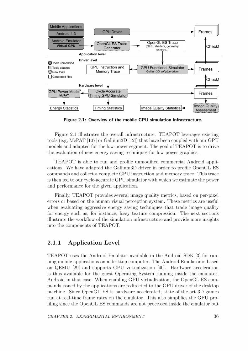
FramesFrames
FramesFramesMobile Applications
Android 4.3
Android EmulatorVirtual GPU
GPU Driver
OpenGL ES TraceGenerator
OpenGL ES Trace(GLSL shaders, geometry,
textures...)
GPU Functional SimulatorGallium3D softpipe driver
GPU Instruction and Memory Trace
Frames
Frames
Check!
Cycle AccurateTiming GPU Simulator
FramesFramesFrames
Check!
GPU Power ModelMcPAT
Image QualityAssessmentEnergy Statistics Timing Statistics Image Quality Statistics
Tools unmodified
Tools adapted
New tools
Generated files
Application level
Driver level
Hardware level
Figure 2.1: Overview of the mobile GPU simulation infrastructure.
Figure 2.1 illustrates the overall infrastructure. TEAPOT leverages existingtools (e.g, McPAT [107] or Gallium3D [12]) that have been coupled with our GPUmodels and adapted for the low-power segment. The goal of TEAPOT is to drivethe evaluation of new energy saving techniques for low-power graphics.
TEAPOT is able to run and profile unmodified commercial Android appli-cations. We have adapted the Gallium3D driver in order to profile OpenGL EScommands and collect a complete GPU instruction and memory trace. This traceis then fed to our cycle-accurate GPU simulator with which we estimate the powerand performance for the given application.
Finally, TEAPOT provides several image quality metrics, based on per-pixelerrors or based on the human visual perception system. These metrics are usefulwhen evaluating aggressive energy saving techniques that trade image qualityfor energy such as, for instance, lossy texture compression. The next sectionsillustrate the workflow of the simulation infrastructure and provide more insightsinto the components of TEAPOT.
2.1.1 Application Level
TEAPOT uses the Android Emulator available in the Android SDK [3] for run-ning mobile applications on a desktop computer. The Android Emulator is basedon QEMU [29] and supports GPU virtualization [40]. Hardware accelerationis thus available for the guest Operating System running inside the emulator,Android in that case. When enabling GPU virtualization, the OpenGL ES com-mands issued by the applications are redirected to the GPU driver of the desktopmachine. Since OpenGL ES is hardware accelerated, state-of-the-art 3D gamesrun at real-time frame rates on the emulator. This also simplifies the GPU pro-filing since the OpenGL ES commands are not processed inside the emulator but
CHAPTER 2. EXPERIMENTAL ENVIRONMENT 36
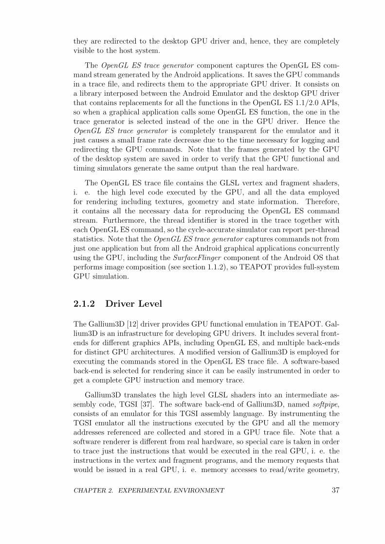
they are redirected to the desktop GPU driver and, hence, they are completelyvisible to the host system.
The OpenGL ES trace generator component captures the OpenGL ES com-mand stream generated by the Android applications. It saves the GPU commandsin a trace file, and redirects them to the appropriate GPU driver. It consists ona library interposed between the Android Emulator and the desktop GPU driverthat contains replacements for all the functions in the OpenGL ES 1.1/2.0 APIs,so when a graphical application calls some OpenGL ES function, the one in thetrace generator is selected instead of the one in the GPU driver. Hence theOpenGL ES trace generator is completely transparent for the emulator and itjust causes a small frame rate decrease due to the time necessary for logging andredirecting the GPU commands. Note that the frames generated by the GPUof the desktop system are saved in order to verify that the GPU functional andtiming simulators generate the same output than the real hardware.
The OpenGL ES trace file contains the GLSL vertex and fragment shaders,i. e. the high level code executed by the GPU, and all the data employedfor rendering including textures, geometry and state information. Therefore,it contains all the necessary data for reproducing the OpenGL ES commandstream. Furthermore, the thread identifier is stored in the trace together witheach OpenGL ES command, so the cycle-accurate simulator can report per-threadstatistics. Note that the OpenGL ES trace generator captures commands not fromjust one application but from all the Android graphical applications concurrentlyusing the GPU, including the SurfaceFlinger component of the Android OS thatperforms image composition (see section 1.1.2), so TEAPOT provides full-systemGPU simulation.
2.1.2 Driver Level
The Gallium3D [12] driver provides GPU functional emulation in TEAPOT. Gal-lium3D is an infrastructure for developing GPU drivers. It includes several front-ends for different graphics APIs, including OpenGL ES, and multiple back-endsfor distinct GPU architectures. A modified version of Gallium3D is employed forexecuting the commands stored in the OpenGL ES trace file. A software-basedback-end is selected for rendering since it can be easily instrumented in order toget a complete GPU instruction and memory trace.
Gallium3D translates the high level GLSL shaders into an intermediate as-sembly code, TGSI [37]. The software back-end of Gallium3D, named softpipe,consists of an emulator for this TGSI assembly language. By instrumenting theTGSI emulator all the instructions executed by the GPU and all the memoryaddresses referenced are collected and stored in a GPU trace file. Note that asoftware renderer is different from real hardware, so special care is taken in orderto trace just the instructions that would be executed in the real GPU, i. e. theinstructions in the vertex and fragment programs, and the memory requests thatwould be issued in a real GPU, i. e. memory accesses to read/write geometry,
CHAPTER 2. EXPERIMENTAL ENVIRONMENT 37
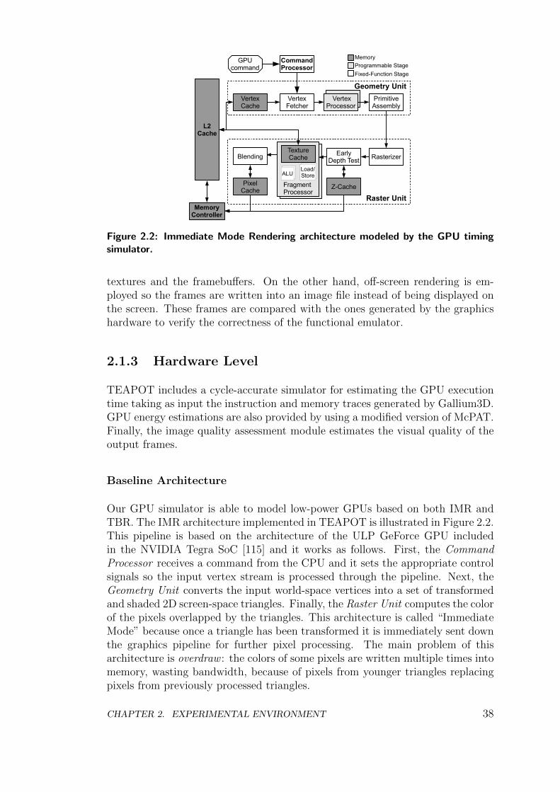
Raster Unit
Fragment Processor
Geometry Unit
GPUcommand
CommandProcessor
MemoryController
VertexFetcher
L2Cache
VertexCache
VertexProcessor
PrimitiveAssembly
Memory
Programmable Stage
Fixed-Function Stage
RasterizerEarlyDepth Test
Z-CachePixelCache
TextureCache
ALULoad/Store
Blending
Figure 2.2: Immediate Mode Rendering architecture modeled by the GPU timingsimulator.
textures and the framebuffers. On the other hand, off-screen rendering is em-ployed so the frames are written into an image file instead of being displayed onthe screen. These frames are compared with the ones generated by the graphicshardware to verify the correctness of the functional emulator.
2.1.3 Hardware Level
TEAPOT includes a cycle-accurate simulator for estimating the GPU executiontime taking as input the instruction and memory traces generated by Gallium3D.GPU energy estimations are also provided by using a modified version of McPAT.Finally, the image quality assessment module estimates the visual quality of theoutput frames.
Baseline Architecture
Our GPU simulator is able to model low-power GPUs based on both IMR andTBR. The IMR architecture implemented in TEAPOT is illustrated in Figure 2.2.This pipeline is based on the architecture of the ULP GeForce GPU includedin the NVIDIA Tegra SoC [115] and it works as follows. First, the CommandProcessor receives a command from the CPU and it sets the appropriate controlsignals so the input vertex stream is processed through the pipeline. Next, theGeometry Unit converts the input world-space vertices into a set of transformedand shaded 2D screen-space triangles. Finally, the Raster Unit computes the colorof the pixels overlapped by the triangles. This architecture is called “ImmediateMode” because once a triangle has been transformed it is immediately sent downthe graphics pipeline for further pixel processing. The main problem of thisarchitecture is overdraw : the colors of some pixels are written multiple times intomemory, wasting bandwidth, because of pixels from younger triangles replacingpixels from previously processed triangles.
CHAPTER 2. EXPERIMENTAL ENVIRONMENT 38
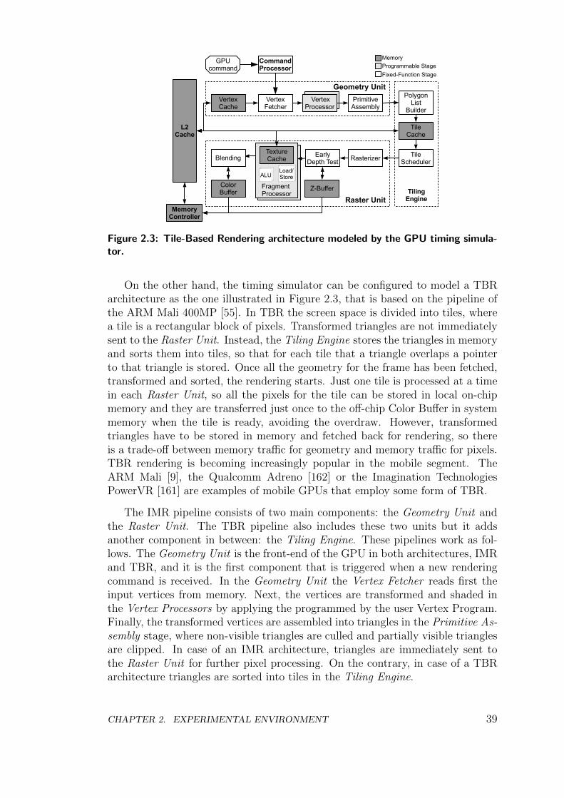
Raster Unit
Fragment Processor
Geometry Unit
GPUcommand
CommandProcessor
MemoryController
VertexFetcher
L2Cache
VertexCache
VertexProcessor
PrimitiveAssembly
TileCache
PolygonList
Builder
TileScheduler
TilingEngine
Memory
Programmable Stage
Fixed-Function Stage
RasterizerEarlyDepth Test
Z-BufferColorBuffer
TextureCache
ALULoad/Store
Blending
Figure 2.3: Tile-Based Rendering architecture modeled by the GPU timing simula-tor.
On the other hand, the timing simulator can be configured to model a TBRarchitecture as the one illustrated in Figure 2.3, that is based on the pipeline ofthe ARM Mali 400MP [55]. In TBR the screen space is divided into tiles, wherea tile is a rectangular block of pixels. Transformed triangles are not immediatelysent to the Raster Unit. Instead, the Tiling Engine stores the triangles in memoryand sorts them into tiles, so that for each tile that a triangle overlaps a pointerto that triangle is stored. Once all the geometry for the frame has been fetched,transformed and sorted, the rendering starts. Just one tile is processed at a timein each Raster Unit, so all the pixels for the tile can be stored in local on-chipmemory and they are transferred just once to the off-chip Color Buffer in systemmemory when the tile is ready, avoiding the overdraw. However, transformedtriangles have to be stored in memory and fetched back for rendering, so thereis a trade-off between memory traffic for geometry and memory traffic for pixels.TBR rendering is becoming increasingly popular in the mobile segment. TheARM Mali [9], the Qualcomm Adreno [162] or the Imagination TechnologiesPowerVR [161] are examples of mobile GPUs that employ some form of TBR.
The IMR pipeline consists of two main components: the Geometry Unit andthe Raster Unit. The TBR pipeline also includes these two units but it addsanother component in between: the Tiling Engine. These pipelines work as fol-lows. The Geometry Unit is the front-end of the GPU in both architectures, IMRand TBR, and it is the first component that is triggered when a new renderingcommand is received. In the Geometry Unit the Vertex Fetcher reads first theinput vertices from memory. Next, the vertices are transformed and shaded inthe Vertex Processors by applying the programmed by the user Vertex Program.Finally, the transformed vertices are assembled into triangles in the Primitive As-sembly stage, where non-visible triangles are culled and partially visible trianglesare clipped. In case of an IMR architecture, triangles are immediately sent tothe Raster Unit for further pixel processing. On the contrary, in case of a TBRarchitecture triangles are sorted into tiles in the Tiling Engine.
CHAPTER 2. EXPERIMENTAL ENVIRONMENT 39
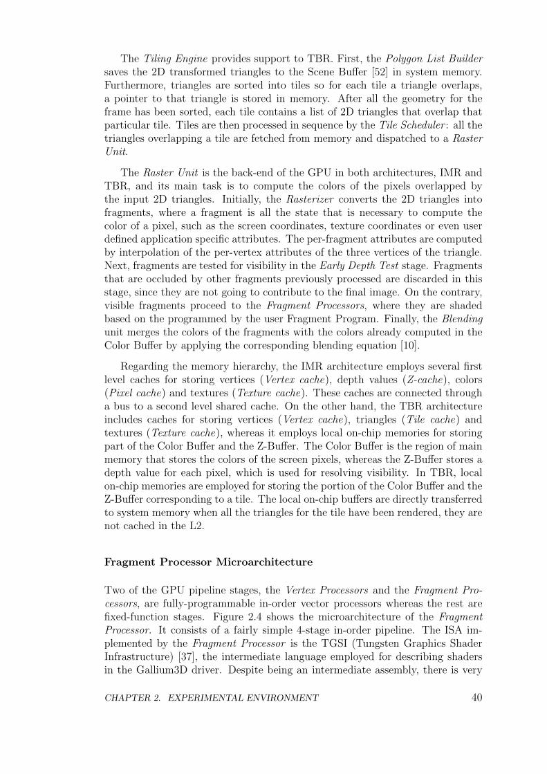
The Tiling Engine provides support to TBR. First, the Polygon List Buildersaves the 2D transformed triangles to the Scene Buffer [52] in system memory.Furthermore, triangles are sorted into tiles so for each tile a triangle overlaps,a pointer to that triangle is stored in memory. After all the geometry for theframe has been sorted, each tile contains a list of 2D triangles that overlap thatparticular tile. Tiles are then processed in sequence by the Tile Scheduler : all thetriangles overlapping a tile are fetched from memory and dispatched to a RasterUnit.
The Raster Unit is the back-end of the GPU in both architectures, IMR andTBR, and its main task is to compute the colors of the pixels overlapped bythe input 2D triangles. Initially, the Rasterizer converts the 2D triangles intofragments, where a fragment is all the state that is necessary to compute thecolor of a pixel, such as the screen coordinates, texture coordinates or even userdefined application specific attributes. The per-fragment attributes are computedby interpolation of the per-vertex attributes of the three vertices of the triangle.Next, fragments are tested for visibility in the Early Depth Test stage. Fragmentsthat are occluded by other fragments previously processed are discarded in thisstage, since they are not going to contribute to the final image. On the contrary,visible fragments proceed to the Fragment Processors, where they are shadedbased on the programmed by the user Fragment Program. Finally, the Blendingunit merges the colors of the fragments with the colors already computed in theColor Buffer by applying the corresponding blending equation [10].
Regarding the memory hierarchy, the IMR architecture employs several firstlevel caches for storing vertices (Vertex cache), depth values (Z-cache), colors(Pixel cache) and textures (Texture cache). These caches are connected througha bus to a second level shared cache. On the other hand, the TBR architectureincludes caches for storing vertices (Vertex cache), triangles (Tile cache) andtextures (Texture cache), whereas it employs local on-chip memories for storingpart of the Color Buffer and the Z-Buffer. The Color Buffer is the region of mainmemory that stores the colors of the screen pixels, whereas the Z-Buffer stores adepth value for each pixel, which is used for resolving visibility. In TBR, localon-chip memories are employed for storing the portion of the Color Buffer and theZ-Buffer corresponding to a tile. The local on-chip buffers are directly transferredto system memory when all the triangles for the tile have been rendered, they arenot cached in the L2.
Fragment Processor Microarchitecture
Two of the GPU pipeline stages, the Vertex Processors and the Fragment Pro-cessors, are fully-programmable in-order vector processors whereas the rest arefixed-function stages. Figure 2.4 shows the microarchitecture of the FragmentProcessor. It consists of a fairly simple 4-stage in-order pipeline. The ISA im-plemented by the Fragment Processor is the TGSI (Tungsten Graphics ShaderInfrastructure) [37], the intermediate language employed for describing shadersin the Gallium3D driver. Despite being an intermediate assembly, there is very
CHAPTER 2. EXPERIMENTAL ENVIRONMENT 40
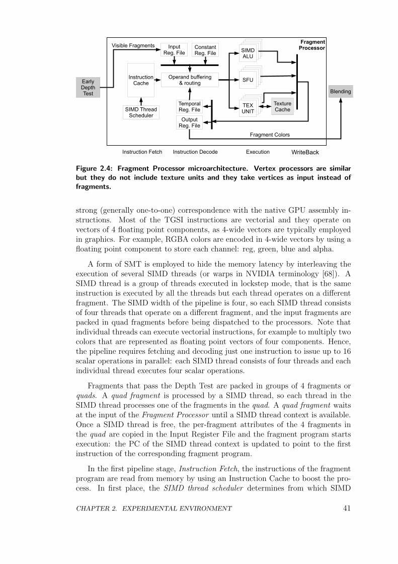
FragmentProcessor
SIMD ThreadScheduler
InstructionCache
InputReg. File
ConstantReg. File
OutputReg. File
TemporalReg. File
Operand buffering& routing
SIMDALU
SFU
TEXUNIT
TextureCache
Instruction Fetch Instruction Decode Execution WriteBack
EarlyDepthTest Blending
Visible Fragments
Fragment Colors
Figure 2.4: Fragment Processor microarchitecture. Vertex processors are similarbut they do not include texture units and they take vertices as input instead offragments.
strong (generally one-to-one) correspondence with the native GPU assembly in-structions. Most of the TGSI instructions are vectorial and they operate onvectors of 4 floating point components, as 4-wide vectors are typically employedin graphics. For example, RGBA colors are encoded in 4-wide vectors by using afloating point component to store each channel: reg, green, blue and alpha.
A form of SMT is employed to hide the memory latency by interleaving theexecution of several SIMD threads (or warps in NVIDIA terminology [68]). ASIMD thread is a group of threads executed in lockstep mode, that is the sameinstruction is executed by all the threads but each thread operates on a differentfragment. The SIMD width of the pipeline is four, so each SIMD thread consistsof four threads that operate on a different fragment, and the input fragments arepacked in quad fragments before being dispatched to the processors. Note thatindividual threads can execute vectorial instructions, for example to multiply twocolors that are represented as floating point vectors of four components. Hence,the pipeline requires fetching and decoding just one instruction to issue up to 16scalar operations in parallel: each SIMD thread consists of four threads and eachindividual thread executes four scalar operations.
Fragments that pass the Depth Test are packed in groups of 4 fragments orquads. A quad fragment is processed by a SIMD thread, so each thread in theSIMD thread processes one of the fragments in the quad. A quad fragment waitsat the input of the Fragment Processor until a SIMD thread context is available.Once a SIMD thread is free, the per-fragment attributes of the 4 fragments inthe quad are copied in the Input Register File and the fragment program startsexecution: the PC of the SIMD thread context is updated to point to the firstinstruction of the corresponding fragment program.
In the first pipeline stage, Instruction Fetch, the instructions of the fragmentprogram are read from memory by using an Instruction Cache to boost the pro-cess. In first place, the SIMD thread scheduler determines from which SIMD
CHAPTER 2. EXPERIMENTAL ENVIRONMENT 41
thread to fetch an instruction by using a Round Robin policy. Next, the PC ofthe selected SIMD thread is employed to send a request to the Instruction Cache.Once the instruction is fetched the PC is updated to point to the next instruction.Note that each SIMD thread has its own PC, but the 4 threads in the same SIMDthread share the PC so all of them execute the same instruction on a differentfragment.
In the next pipeline stage, Instruction Decode, the source operands are fetchedfrom the main register file. Each thread has available a set of 16 input registersfor storing per-fragment attributes such as the screen coordinates or the texturecoordinates, a set of 12 temporal registers for intermediate computations, and aset of 8 output registers for storing the result of the fragment program. Further-more, a set of 96 constant registers is shared by all the threads, constant registerscontain global state information such as the number of lights enabled. All theseregisters are vectorial and consist of 16 bytes split in 4 floating point components.One thread has 36 registers (16 input, 12 temporal, 8 output), so it requires 576bytes of storage and, hence, a SIMD thread context requires 2304 bytes in themain register file. The register file is organized in 4 banks, each one having theregisters of one of the threads in a SIMD thread. Furthermore, each bank has 3read ports and 1 write port. By using this organization, all the source operandsfor the four threads in a SIMD thread can be fetched in just one cycle, even forthe MAD (multiply-add) instruction that requires 3 source operands. The de-code logic reads the source operands of the given instruction and dispatches theoperands to the functional units.
In the next pipeline stage, Execution, the instruction is executed in the cor-responding functional unit. Three types of functional units are included in eachFragment Processor. The SIMD ALU executes vectorial operations such as addi-tions or multiplications. The SFU (Special Functions Unit) executes more com-plex operations such as reciprocal or square root. Finally, the Texture Unitcomputes the color of a texture at a given coordinates. The functional units arepipelined so a new instruction can be issued every cycle. Furthermore, a Frag-ment Processor includes 4 SIMD units, 4 SFU units and 4 Texture Units, so theoperations for the 4 threads in one SIMD thread can be issued in parallel in thesame cycle. This means that 16 scalar operations can be executed in parallel.
The Texture Unit consists of 3 stages. First, the addresses of the texels(texture elements) are generated by using the texture coordinates of the fragmentand the base address of the target texture. In the second stage, the memoryrequests to fetch the texels are issued to the texture cache. In the final stage, thecolors of the texels are combined by applying the corresponding texture filter, thisrequires linear or trilinear interpolation to obtain the final color. The FragmentProcessor includes a texture cache to boost the process of fetching the texels frommemory. In case of a cache miss in the texture cache, the SIMD thread is markedas blocked and it is not selected for execution by the SIMD Thread Scheduler.By doing this, the Fragment Processor does not fetch instructions from SIMDthreads that are waiting for long latency operations. Once the texture instructionis resolved, the SIMD thread is marked again as ready for execution.
CHAPTER 2. EXPERIMENTAL ENVIRONMENT 42
In the last pipeline stage, Writeback, the result of the instruction is writtenin the temporal or in the output register file. Scoreboarding is employed to trackdependencies. The destination register is marked as “not available” in the decodestage and it is marked as “available” when its value is written in the writebackstage. On the other hand, no forwarding mechanism is present in the pipeline.However, consecutive instructions usually belong to different SIMD threads sinceRound Robin is employed and, hence, instructions executed back-to-back areindependent.
The end of the fragment program is signaled by a special instruction in theISA. This “end of program” instruction reads the results of the fragment program,i. e. the colors of the fragments, from the output register file and it dispatchesthe colors to the next GPU stage, the Blending. Furthermore, the SIMD threadcontext is marked as free so a new quad fragment can be assigned to the context.
Vertex Processors are similar to Fragment Processors, but the SIMD threadsoperate on four different vertices instead of fragments. Furthermore, they donot have to handle texture instructions so they do not include Texture units orTexture caches. We assume a non-unified architecture as opposed to a unifiedarchitecture where all the processors can handle both vertices and fragments.Usually, unified architectures offer better workload balance, whereas non-unifiedarchitectures can exploit the difference between vertex and fragment processingto build more specialized and optimized processors. For instance, the resultsobtained by using McPAT indicate that a Vertex Processor has just 64% of thearea of a Fragment Processor.
TEAPOT reports statistics per-frame and per-thread. Since GPU commandsare tagged with the thread identifier, TEAPOT is able to assign fractions of GPUexecution time and energy to each application.
System Memory Simulation
The GPU timing simulator of TEAPOT employs DRAMSim2 [133] to accuratelymodel system memory. DRAMSim2 simulates a DDR2/3 memory system, includ-ing a detailed cycle accurate model of the memory controller, memory channels,DRAM ranks and banks.
Cycle accurate simulators typically employ fixed memory latencies for theoff-chip accesses to main memory. Such a simplistic approach fails to provide arealistic estimation of the cost of accessing main memory, as real memory systemsexhibit highly complex behavior that produces significantly different latencies fordifferent memory accesses. For example, the DRAM refresh is a major sourceof variance in the latency of the memory requests, as read requests that areissued while a refresh is in progress have to wait much longer than other requests.DRAMSim2 is employed in TEAPOT to accurately model the behavior of systemmemory and, hence, off-chip memory accesses exhibit variable latency.
CHAPTER 2. EXPERIMENTAL ENVIRONMENT 43
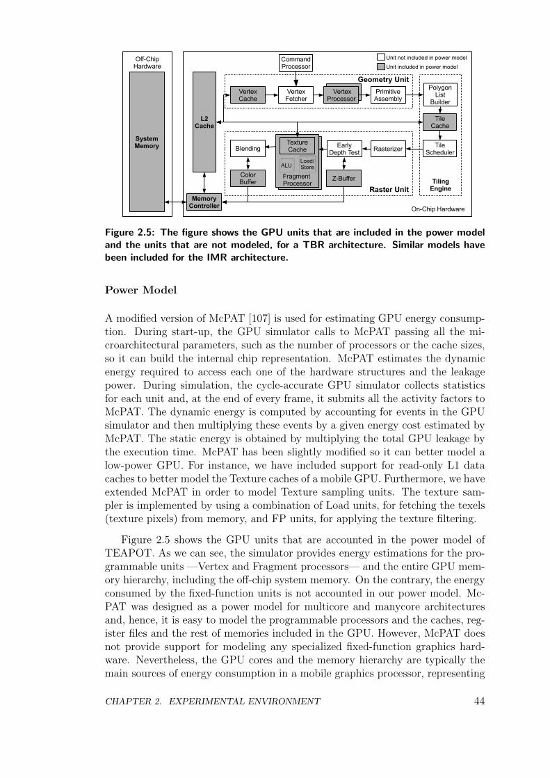
On-Chip Hardware
Raster Unit
Fragment Processor
Geometry Unit
CommandProcessor
MemoryController
VertexFetcher
L2Cache
VertexCache
VertexProcessor
PrimitiveAssembly
TileCache
PolygonList
Builder
TileScheduler
TilingEngine
Unit not included in power model
Unit included in power model
RasterizerEarlyDepth Test
Z-BufferColorBuffer
TextureCache
ALULoad/Store
Blending
Off-ChipHardware
SystemMemory
Figure 2.5: The figure shows the GPU units that are included in the power modeland the units that are not modeled, for a TBR architecture. Similar models havebeen included for the IMR architecture.
Power Model
A modified version of McPAT [107] is used for estimating GPU energy consump-tion. During start-up, the GPU simulator calls to McPAT passing all the mi-croarchitectural parameters, such as the number of processors or the cache sizes,so it can build the internal chip representation. McPAT estimates the dynamicenergy required to access each one of the hardware structures and the leakagepower. During simulation, the cycle-accurate GPU simulator collects statisticsfor each unit and, at the end of every frame, it submits all the activity factors toMcPAT. The dynamic energy is computed by accounting for events in the GPUsimulator and then multiplying these events by a given energy cost estimated byMcPAT. The static energy is obtained by multiplying the total GPU leakage bythe execution time. McPAT has been slightly modified so it can better model alow-power GPU. For instance, we have included support for read-only L1 datacaches to better model the Texture caches of a mobile GPU. Furthermore, we haveextended McPAT in order to model Texture sampling units. The texture sam-pler is implemented by using a combination of Load units, for fetching the texels(texture pixels) from memory, and FP units, for applying the texture filtering.
Figure 2.5 shows the GPU units that are accounted in the power model ofTEAPOT. As we can see, the simulator provides energy estimations for the pro-grammable units —Vertex and Fragment processors— and the entire GPU mem-ory hierarchy, including the off-chip system memory. On the contrary, the energyconsumed by the fixed-function units is not accounted in our power model. Mc-PAT was designed as a power model for multicore and manycore architecturesand, hence, it is easy to model the programmable processors and the caches, reg-ister files and the rest of memories included in the GPU. However, McPAT doesnot provide support for modeling any specialized fixed-function graphics hard-ware. Nevertheless, the GPU cores and the memory hierarchy are typically themain sources of energy consumption in a mobile graphics processor, representing
CHAPTER 2. EXPERIMENTAL ENVIRONMENT 44
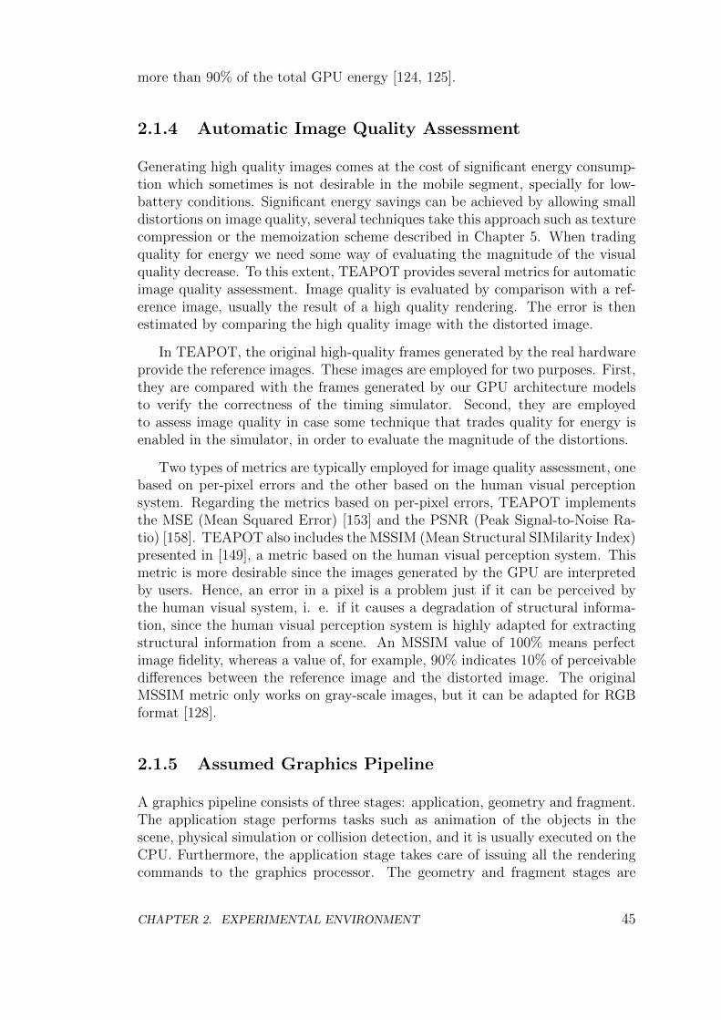
more than 90% of the total GPU energy [124, 125].
2.1.4 Automatic Image Quality Assessment
Generating high quality images comes at the cost of significant energy consump-tion which sometimes is not desirable in the mobile segment, specially for low-battery conditions. Significant energy savings can be achieved by allowing smalldistortions on image quality, several techniques take this approach such as texturecompression or the memoization scheme described in Chapter 5. When tradingquality for energy we need some way of evaluating the magnitude of the visualquality decrease. To this extent, TEAPOT provides several metrics for automaticimage quality assessment. Image quality is evaluated by comparison with a ref-erence image, usually the result of a high quality rendering. The error is thenestimated by comparing the high quality image with the distorted image.
In TEAPOT, the original high-quality frames generated by the real hardwareprovide the reference images. These images are employed for two purposes. First,they are compared with the frames generated by our GPU architecture modelsto verify the correctness of the timing simulator. Second, they are employedto assess image quality in case some technique that trades quality for energy isenabled in the simulator, in order to evaluate the magnitude of the distortions.
Two types of metrics are typically employed for image quality assessment, onebased on per-pixel errors and the other based on the human visual perceptionsystem. Regarding the metrics based on per-pixel errors, TEAPOT implementsthe MSE (Mean Squared Error) [153] and the PSNR (Peak Signal-to-Noise Ra-tio) [158]. TEAPOT also includes the MSSIM (Mean Structural SIMilarity Index)presented in [149], a metric based on the human visual perception system. Thismetric is more desirable since the images generated by the GPU are interpretedby users. Hence, an error in a pixel is a problem just if it can be perceived bythe human visual system, i. e. if it causes a degradation of structural informa-tion, since the human visual perception system is highly adapted for extractingstructural information from a scene. An MSSIM value of 100% means perfectimage fidelity, whereas a value of, for example, 90% indicates 10% of perceivabledifferences between the reference image and the distorted image. The originalMSSIM metric only works on gray-scale images, but it can be adapted for RGBformat [128].
2.1.5 Assumed Graphics Pipeline
A graphics pipeline consists of three stages: application, geometry and fragment.The application stage performs tasks such as animation of the objects in thescene, physical simulation or collision detection, and it is usually executed on theCPU. Furthermore, the application stage takes care of issuing all the renderingcommands to the graphics processor. The geometry and fragment stages are
CHAPTER 2. EXPERIMENTAL ENVIRONMENT 45
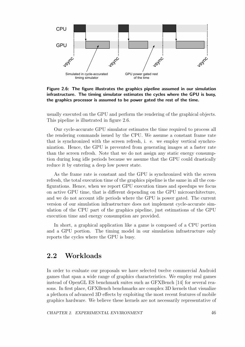
CPU
GPU
vsyn
c
vsyn
c
vsyn
c
vsyn
c
Simulated in cycle-accuratedtiming simulator
GPU power gated restof the time
Figure 2.6: The figure illustrates the graphics pipeline assumed in our simulationinfrastructure. The timing simulator estimates the cycles where the GPU is busy,the graphics processor is assumed to be power gated the rest of the time.
usually executed on the GPU and perform the rendering of the graphical objects.This pipeline is illustrated in figure 2.6.
Our cycle-accurate GPU simulator estimates the time required to process allthe rendering commands issued by the CPU. We assume a constant frame ratethat is synchronized with the screen refresh, i. e. we employ vertical synchro-nization. Hence, the GPU is prevented from generating images at a faster ratethan the screen refresh. Note that we do not assign any static energy consump-tion during long idle periods because we assume that the GPU could drasticallyreduce it by entering a deep low power state.
As the frame rate is constant and the GPU is synchronized with the screenrefresh, the total execution time of the graphics pipeline is the same in all the con-figurations. Hence, when we report GPU execution times and speedups we focuson active GPU time, that is different depending on the GPU microarchitecture,and we do not account idle periods where the GPU is power gated. The currentversion of our simulation infrastructure does not implement cycle-accurate sim-ulation of the CPU part of the graphics pipeline, just estimations of the GPUexecution time and energy consumption are provided.
In short, a graphical application like a game is composed of a CPU portionand a GPU portion. The timing model in our simulation infrastructure onlyreports the cycles where the GPU is busy.
2.2 Workloads
In order to evaluate our proposals we have selected twelve commercial Androidgames that span a wide range of graphics characteristics. We employ real gamesinstead of OpenGL ES benchmark suites such as GFXBench [14] for several rea-sons. In first place, GFXBench benchmarks are complex 3D kernels that visualizea plethora of advanced 3D effects by exploiting the most recent features of mobilegraphics hardware. We believe these kernels are not necessarily representative of
CHAPTER 2. EXPERIMENTAL ENVIRONMENT 46
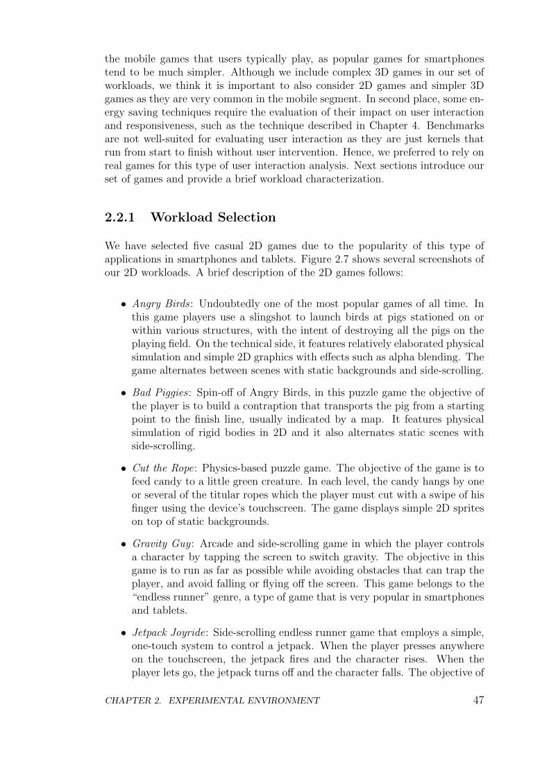
the mobile games that users typically play, as popular games for smartphonestend to be much simpler. Although we include complex 3D games in our set ofworkloads, we think it is important to also consider 2D games and simpler 3Dgames as they are very common in the mobile segment. In second place, some en-ergy saving techniques require the evaluation of their impact on user interactionand responsiveness, such as the technique described in Chapter 4. Benchmarksare not well-suited for evaluating user interaction as they are just kernels thatrun from start to finish without user intervention. Hence, we preferred to rely onreal games for this type of user interaction analysis. Next sections introduce ourset of games and provide a brief workload characterization.
2.2.1 Workload Selection
We have selected five casual 2D games due to the popularity of this type ofapplications in smartphones and tablets. Figure 2.7 shows several screenshots ofour 2D workloads. A brief description of the 2D games follows:
• Angry Birds : Undoubtedly one of the most popular games of all time. Inthis game players use a slingshot to launch birds at pigs stationed on orwithin various structures, with the intent of destroying all the pigs on theplaying field. On the technical side, it features relatively elaborated physicalsimulation and simple 2D graphics with effects such as alpha blending. Thegame alternates between scenes with static backgrounds and side-scrolling.
• Bad Piggies : Spin-off of Angry Birds, in this puzzle game the objective ofthe player is to build a contraption that transports the pig from a startingpoint to the finish line, usually indicated by a map. It features physicalsimulation of rigid bodies in 2D and it also alternates static scenes withside-scrolling.
• Cut the Rope: Physics-based puzzle game. The objective of the game is tofeed candy to a little green creature. In each level, the candy hangs by oneor several of the titular ropes which the player must cut with a swipe of hisfinger using the device’s touchscreen. The game displays simple 2D spriteson top of static backgrounds.
• Gravity Guy : Arcade and side-scrolling game in which the player controlsa character by tapping the screen to switch gravity. The objective in thisgame is to run as far as possible while avoiding obstacles that can trap theplayer, and avoid falling or flying off the screen. This game belongs to the“endless runner” genre, a type of game that is very popular in smartphonesand tablets.
• Jetpack Joyride: Side-scrolling endless runner game that employs a simple,one-touch system to control a jetpack. When the player presses anywhereon the touchscreen, the jetpack fires and the character rises. When theplayer lets go, the jetpack turns off and the character falls. The objective of
CHAPTER 2. EXPERIMENTAL ENVIRONMENT 47
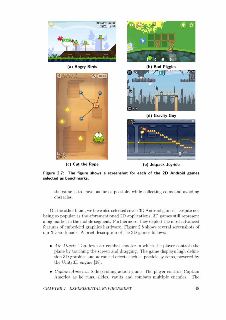
(a) Angry Birds (b) Bad Piggies
(c) Cut the Rope
(d) Gravity Guy
(e) Jetpack Joyride
Figure 2.7: The figure shows a screenshot for each of the 2D Android gamesselected as benchmarks.
the game is to travel as far as possible, while collecting coins and avoidingobstacles.
On the other hand, we have also selected seven 3D Android games. Despite notbeing so popular as the aforementioned 2D applications, 3D games still representa big market in the mobile segment. Furthermore, they exploit the most advancedfeatures of embedded graphics hardware. Figure 2.8 shows several screenshots ofour 3D workloads. A brief description of the 3D games follows:
• Air Attack : Top-down air combat shooter in which the player controls theplane by touching the screen and dragging. The game displays high defini-tion 3D graphics and advanced effects such as particle systems, powered bythe Unity3D engine [38].
• Captain America: Side-scrolling action game. The player controls CaptainAmerica as he runs, slides, vaults and combats multiple enemies. The
CHAPTER 2. EXPERIMENTAL ENVIRONMENT 48
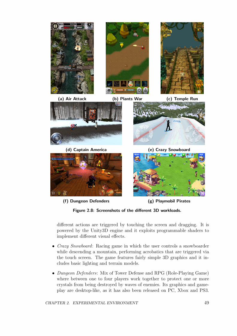
(a) Air Attack (b) Plants War (c) Temple Run
(d) Captain America (e) Crazy Snowboard
(f) Dungeon Defenders (g) Playmobil Pirates
Figure 2.8: Screenshots of the different 3D workloads.
different actions are triggered by touching the screen and dragging. It ispowered by the Unity3D engine and it exploits programmable shaders toimplement different visual effects.
• Crazy Snowboard : Racing game in which the user controls a snowboarderwhile descending a mountain, performing acrobatics that are triggered viathe touch screen. The game features fairly simple 3D graphics and it in-cludes basic lighting and terrain models.
• Dungeon Defenders : Mix of Tower Defense and RPG (Role-Playing Game)where between one to four players work together to protect one or morecrystals from being destroyed by waves of enemies. Its graphics and game-play are desktop-like, as it has also been released on PC, Xbox and PS3.
CHAPTER 2. EXPERIMENTAL ENVIRONMENT 49
The game features advanced 3D graphics powered by the Unreal Engine [39]and supports a plethora of 3D effects.
• Plants War : Real-time strategy game in which the player has to manageresources and build his own army to defeat the enemy troops. Plants Wardisplays simple 3D graphics, as it employs basic lighting models and 3Dobjects with low polygon counts.
• Playmobil Pirates : Combination of strategy and action game. The playerhas to build and control his own pirate fortress and fleet to protect the trea-sure of his island. The game displays high definition 3D graphics, includingadvanced effects such as water rendering, projected shadows or particlesystems.
• Temple Run: One of the most popular endless runner games. The playertakes on the role of an explorer who, having stolen an idol from a temple,is chased by evil monkeys. The player has to swipe to turn, jump and slideto avoid obstacles and collect coins. The game displays relatively complex3D graphics powered by the Unity3D engine, and it includes some effectssuch as water rendering.
Our workloads are representative of the mobile graphical applications as wehave included some of the most popular games available for smartphones. Fur-thermore, our set of workloads cover most of the features available in the OpenGLES 1.1/2.0 APIs [96, 95]. We provide more detailed explanations of why we haveselected these concrete games in section 2.2.2. Note that despite Khronos hasalready released OpenGL ES 3.0/3.1 [97, 98], the new specifications of the APIare very recent —December 2013 and March 2014 for 3.0 and 3.1 respectively—and thus all the games available for Android still employ OpenGL ES 1.1/2.0 atthe time of writing.
On the other hand, we have focused on the game genres that are more popularin smartphones and tablets. For example, First-Person Shooters (FPS) are verypopular in PC and desktop platforms, but they represent a small market in themobile segment as it is difficult to play these games by using a touch screen.Casual games, physics-based puzzle games or endless runner games are muchmore common in mobile devices as they better exploit the smartphone’s userinterfaces.
Note that we have not included any OpenCL/CUDA workload despite thegrowing interest in General Purpose Computing on the GPU (GPGPU). Thesupport for OpenCL and CUDA in the mobile segment has been non-existentor very poor in the best case during past years, and only the most recent mo-bile GPUs and Android versions begin to truly support GPGPU. On the otherhand, CUDA/OpenCL are typically employed to boost scientific applications.We believe that mobile phones are not the ideal platform for scientific codes,so our research is focused on more typical workloads for smartphones. Othercomputationally intensive tasks that are common in smartphones and could be
CHAPTER 2. EXPERIMENTAL ENVIRONMENT 50
offloaded to the GPU, such as image processing or video decoding, are usuallyhandled by ASICs included in the SoC that are extremely energy-efficient exe-cuting these specific tasks. We are not claiming that GPGPU is useless in themobile segment, since the GPU offers much more flexibility than the ASICs andit is much more energy-efficiency than the CPU for data-parallel workloads. Weare only highlighting the fact that it currently has a smaller presence in smart-phones. Nevertheless, the current trends in mobile graphics hardware indicatethat GPGPU support will be much more widespread and of much higher qualityin next years. We believe that, for example, analyzing the use of OpenGL ES3.1 compute shaders to boost physics simulation or collision detection is an in-triguing direction. We leave this type of study for future work, and we proposesimple ways of improving our simulation infrastructure to support GPGPU inChapter 6.
2.2.2 Workload Characterization
In this section we provide a brief workload characterization of our set of games.As these applications are not the conventional benchmarks employed in computerarchitecture, we think it is worth including a short analysis of their characteristics.We have employed our OpenGL ES Trace Generator, described in section 2.1.1, tocollect traces of the OpenGL ES calls as seen in our Android games. The resultsreported in this section have been obtained by analyzing traces of 400 frames foreach game, the scenes have been rendered at WVGA (800 × 480) resolution.
Table 2.1 provides a general description of the workloads. It includes thetype of game —2D or 3D—, the date were the last update of the game wasreleased, the approximate number of downloads as reported by Google Play, thegame engine and the version of the OpenGL ES API. As we can see, the gameshave been developed in recent years. Most of them have been updated recently,whereas the oldest game, captainamerica, received its last update by 2011. Inaddition, these games have been downloaded and installed at least more thanone million times, and we have included some of the most popular games such asangrybirds, cuttherope or templerun that have been downloaded more than onehundred million times in Google Play.
Regarding the game engine, five of the games employ Unity3D. Unity3D is astate-of-the-art cross-platform game engine developed by Unity Technologies thatis commonly employed to create games for mobile devices. Unity3D supportsadvanced 3D effects such as normal mapping or dynamic shadows. On the otherhand three of the games, cuttherope, gravityguy and jetpackjoyride, employ theirown custom developed game engine. As mobile games tend to be simpler, somesmall companies opt by developing their own rendering solutions. This is differentfrom the desktop platform where developing the engines that support modern 3Dgames would take years and, hence, developers usually rely on mature gamedevelopment kits. Finally, we have included a game that employs the UnrealEngine 3, dungeondefenders. Unreal Engine is one of the best engines available
CHAPTER 2. EXPERIMENTAL ENVIRONMENT 51
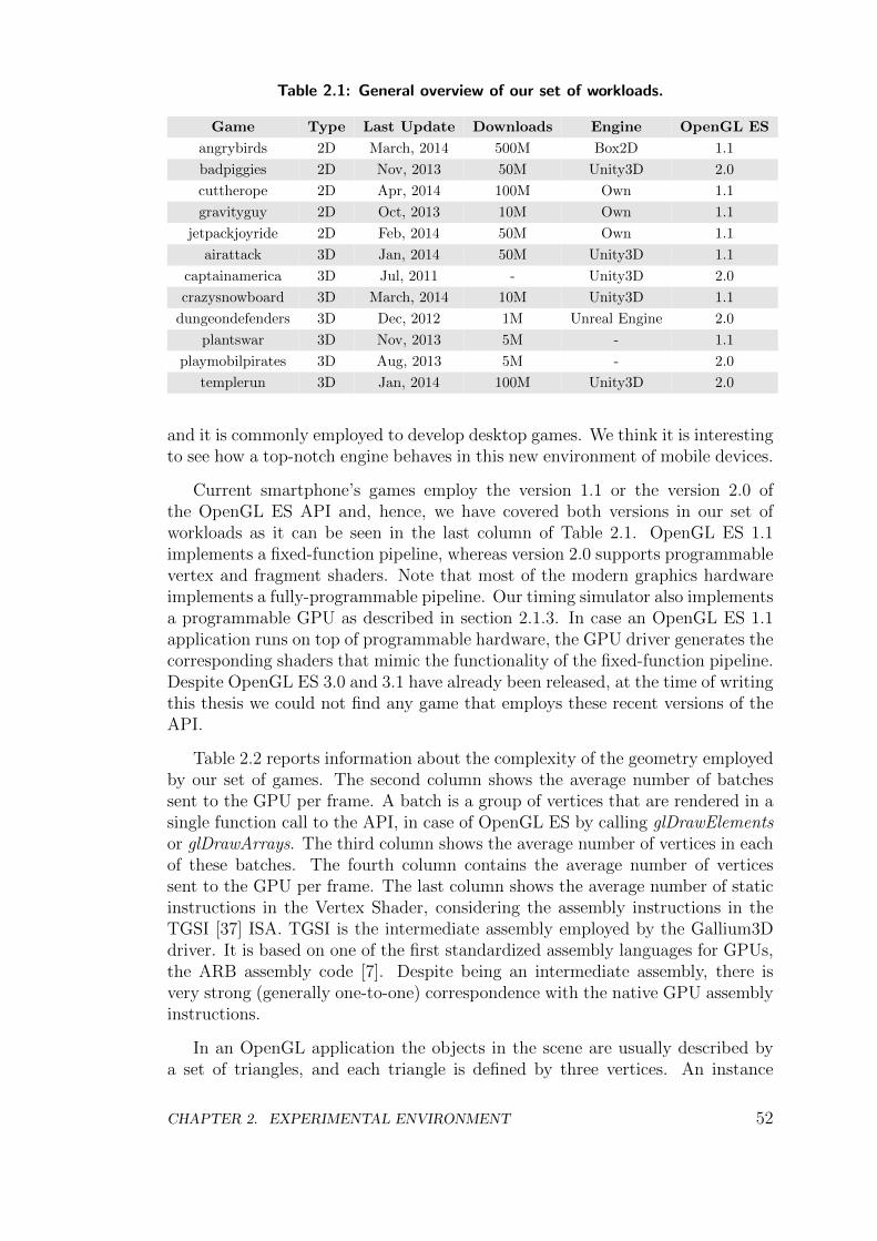
Table 2.1: General overview of our set of workloads.
Game Type Last Update Downloads Engine OpenGL ES
angrybirds 2D March, 2014 500M Box2D 1.1
badpiggies 2D Nov, 2013 50M Unity3D 2.0
cuttherope 2D Apr, 2014 100M Own 1.1
gravityguy 2D Oct, 2013 10M Own 1.1
jetpackjoyride 2D Feb, 2014 50M Own 1.1
airattack 3D Jan, 2014 50M Unity3D 1.1
captainamerica 3D Jul, 2011 - Unity3D 2.0
crazysnowboard 3D March, 2014 10M Unity3D 1.1
dungeondefenders 3D Dec, 2012 1M Unreal Engine 2.0
plantswar 3D Nov, 2013 5M - 1.1
playmobilpirates 3D Aug, 2013 5M - 2.0
templerun 3D Jan, 2014 100M Unity3D 2.0
and it is commonly employed to develop desktop games. We think it is interestingto see how a top-notch engine behaves in this new environment of mobile devices.
Current smartphone’s games employ the version 1.1 or the version 2.0 ofthe OpenGL ES API and, hence, we have covered both versions in our set ofworkloads as it can be seen in the last column of Table 2.1. OpenGL ES 1.1implements a fixed-function pipeline, whereas version 2.0 supports programmablevertex and fragment shaders. Note that most of the modern graphics hardwareimplements a fully-programmable pipeline. Our timing simulator also implementsa programmable GPU as described in section 2.1.3. In case an OpenGL ES 1.1application runs on top of programmable hardware, the GPU driver generates thecorresponding shaders that mimic the functionality of the fixed-function pipeline.Despite OpenGL ES 3.0 and 3.1 have already been released, at the time of writingthis thesis we could not find any game that employs these recent versions of theAPI.
Table 2.2 reports information about the complexity of the geometry employedby our set of games. The second column shows the average number of batchessent to the GPU per frame. A batch is a group of vertices that are rendered in asingle function call to the API, in case of OpenGL ES by calling glDrawElementsor glDrawArrays. The third column shows the average number of vertices in eachof these batches. The fourth column contains the average number of verticessent to the GPU per frame. The last column shows the average number of staticinstructions in the Vertex Shader, considering the assembly instructions in theTGSI [37] ISA. TGSI is the intermediate assembly employed by the Gallium3Ddriver. It is based on one of the first standardized assembly languages for GPUs,the ARB assembly code [7]. Despite being an intermediate assembly, there isvery strong (generally one-to-one) correspondence with the native GPU assemblyinstructions.
In an OpenGL application the objects in the scene are usually described bya set of triangles, and each triangle is defined by three vertices. An instance
CHAPTER 2. EXPERIMENTAL ENVIRONMENT 52
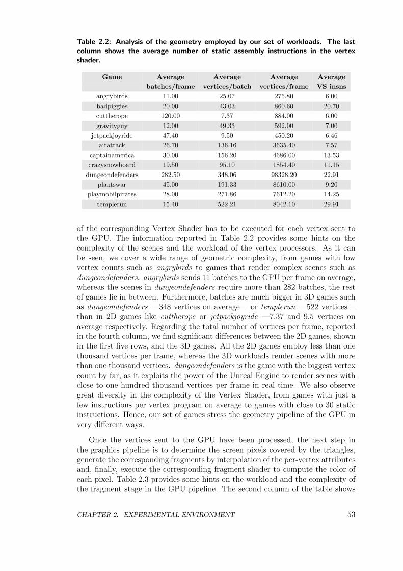
Table 2.2: Analysis of the geometry employed by our set of workloads. The lastcolumn shows the average number of static assembly instructions in the vertexshader.
Game Average Average Average Average
batches/frame vertices/batch vertices/frame VS insns
angrybirds 11.00 25.07 275.80 6.00
badpiggies 20.00 43.03 860.60 20.70
cuttherope 120.00 7.37 884.00 6.00
gravityguy 12.00 49.33 592.00 7.00
jetpackjoyride 47.40 9.50 450.20 6.46
airattack 26.70 136.16 3635.40 7.57
captainamerica 30.00 156.20 4686.00 13.53
crazysnowboard 19.50 95.10 1854.40 11.15
dungeondefenders 282.50 348.06 98328.20 22.91
plantswar 45.00 191.33 8610.00 9.20
playmobilpirates 28.00 271.86 7612.20 14.25
templerun 15.40 522.21 8042.10 29.91
of the corresponding Vertex Shader has to be executed for each vertex sent tothe GPU. The information reported in Table 2.2 provides some hints on thecomplexity of the scenes and the workload of the vertex processors. As it canbe seen, we cover a wide range of geometric complexity, from games with lowvertex counts such as angrybirds to games that render complex scenes such asdungeondefenders. angrybirds sends 11 batches to the GPU per frame on average,whereas the scenes in dungeondefenders require more than 282 batches, the restof games lie in between. Furthermore, batches are much bigger in 3D games suchas dungeondefenders —348 vertices on average— or templerun —522 vertices—than in 2D games like cuttherope or jetpackjoyride —7.37 and 9.5 vertices onaverage respectively. Regarding the total number of vertices per frame, reportedin the fourth column, we find significant differences between the 2D games, shownin the first five rows, and the 3D games. All the 2D games employ less than onethousand vertices per frame, whereas the 3D workloads render scenes with morethan one thousand vertices. dungeondefenders is the game with the biggest vertexcount by far, as it exploits the power of the Unreal Engine to render scenes withclose to one hundred thousand vertices per frame in real time. We also observegreat diversity in the complexity of the Vertex Shader, from games with just afew instructions per vertex program on average to games with close to 30 staticinstructions. Hence, our set of games stress the geometry pipeline of the GPU invery different ways.
Once the vertices sent to the GPU have been processed, the next step inthe graphics pipeline is to determine the screen pixels covered by the triangles,generate the corresponding fragments by interpolation of the per-vertex attributesand, finally, execute the corresponding fragment shader to compute the color ofeach pixel. Table 2.3 provides some hints on the workload and the complexity ofthe fragment stage in the GPU pipeline. The second column of the table shows
CHAPTER 2. EXPERIMENTAL ENVIRONMENT 53
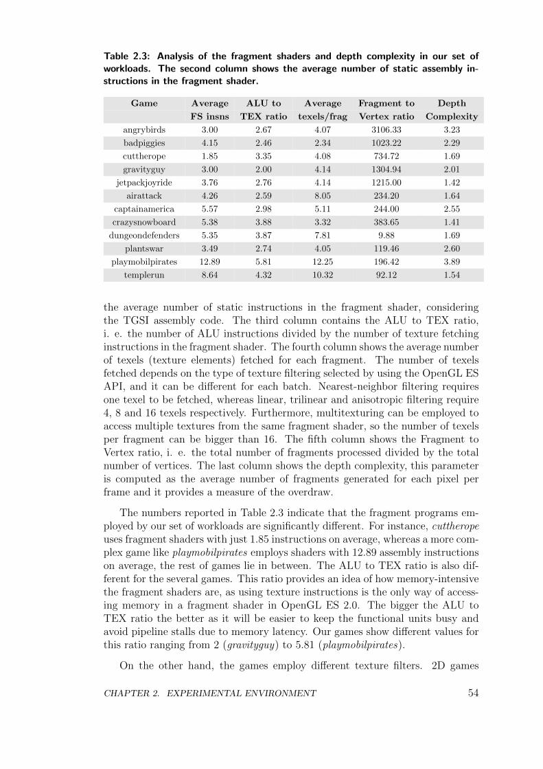
Table 2.3: Analysis of the fragment shaders and depth complexity in our set ofworkloads. The second column shows the average number of static assembly in-structions in the fragment shader.
Game Average ALU to Average Fragment to Depth
FS insns TEX ratio texels/frag Vertex ratio Complexity
angrybirds 3.00 2.67 4.07 3106.33 3.23
badpiggies 4.15 2.46 2.34 1023.22 2.29
cuttherope 1.85 3.35 4.08 734.72 1.69
gravityguy 3.00 2.00 4.14 1304.94 2.01
jetpackjoyride 3.76 2.76 4.14 1215.00 1.42
airattack 4.26 2.59 8.05 234.20 1.64
captainamerica 5.57 2.98 5.11 244.00 2.55
crazysnowboard 5.38 3.88 3.32 383.65 1.41
dungeondefenders 5.35 3.87 7.81 9.88 1.69
plantswar 3.49 2.74 4.05 119.46 2.60
playmobilpirates 12.89 5.81 12.25 196.42 3.89
templerun 8.64 4.32 10.32 92.12 1.54
the average number of static instructions in the fragment shader, consideringthe TGSI assembly code. The third column contains the ALU to TEX ratio,i. e. the number of ALU instructions divided by the number of texture fetchinginstructions in the fragment shader. The fourth column shows the average numberof texels (texture elements) fetched for each fragment. The number of texelsfetched depends on the type of texture filtering selected by using the OpenGL ESAPI, and it can be different for each batch. Nearest-neighbor filtering requiresone texel to be fetched, whereas linear, trilinear and anisotropic filtering require4, 8 and 16 texels respectively. Furthermore, multitexturing can be employed toaccess multiple textures from the same fragment shader, so the number of texelsper fragment can be bigger than 16. The fifth column shows the Fragment toVertex ratio, i. e. the total number of fragments processed divided by the totalnumber of vertices. The last column shows the depth complexity, this parameteris computed as the average number of fragments generated for each pixel perframe and it provides a measure of the overdraw.
The numbers reported in Table 2.3 indicate that the fragment programs em-ployed by our set of workloads are significantly different. For instance, cuttheropeuses fragment shaders with just 1.85 instructions on average, whereas a more com-plex game like playmobilpirates employs shaders with 12.89 assembly instructionson average, the rest of games lie in between. The ALU to TEX ratio is also dif-ferent for the several games. This ratio provides an idea of how memory-intensivethe fragment shaders are, as using texture instructions is the only way of access-ing memory in a fragment shader in OpenGL ES 2.0. The bigger the ALU toTEX ratio the better as it will be easier to keep the functional units busy andavoid pipeline stalls due to memory latency. Our games show different values forthis ratio ranging from 2 (gravityguy) to 5.81 (playmobilpirates).
On the other hand, the games employ different texture filters. 2D games
CHAPTER 2. EXPERIMENTAL ENVIRONMENT 54
prefer a combination of nearest-neighbor and linear filtering, requiring around4 texture fetches per fragment. Some 3D games extensively employ trilinearfiltering, fetching around 8 texels per fragment such as airattack and dungeonde-fenders. Finally, 3D games like playmobilpirates and templerun make extensiveuse of multitexturing and trilinear filtering, demanding more than 10 texels perfragment on average.
The fifth column of Table 2.3 contains the Fragment to Vertex ratio. Thisratio indicates whether a game is geometry bound or fragment bound, i. e. ifthe main bottleneck in the pipeline will be the vertex processors or the fragmentprocessors. Games are typically fragment bound since the GPU has to processmany more fragments than vertices, this is also the case in our workloads. 2Dgames are especially fragment bound as the number of fragments to be shaded isthree orders of magnitude bigger than the number of vertices. 3D games are alsofragment bound, although the number of vertices is much closer to the number offragments than in 2D games, being just between one and two orders of magnitudesmaller. dungeondefenders is the most geometry intensive game, as the numberof fragments is just 9.88 times bigger than the number of vertices.
The last column of Table 2.3 contains the overdraw. As we mentioned insection 1.3.3, overdraw is an important issue as it can cause multiple writes toeach pixel in the Color Buffer and multiple executions of the fragment shaderper pixel, wasting bandwidth, time and energy. Our workloads exhibit differentdepth complexities, ranging from 1.41 fragments per pixel in crazysnowboard to3.89 fragments in playmobilpirates.
In short, we have selected a set of workloads that extensively cover the fullspectrum of mobile graphical applications. Our workloads include some of themost popular applications for smartphones and, furthermore, they exhibit dif-ferent degrees of graphics complexity and make completely different use of thegeometry and fragment pipelines.
2.3 Summary of Methodology
Regarding our evaluation methodology, we employ TEAPOT to run the An-droid games described in section 2.2.1. We have collected OpenGL ES traces of400 frames for each game by using the OpenGL ES trace generator available inTEAPOT. Furthermore, we have executed the traces in the GPU functional em-ulator to generate a complete GPU instruction and memory trace for each game.Finally, the GPU instruction and memory traces are used to drive the cycle-accurate timing simulator. The simulator models both IMR and TBR. The IMRarchitecture implemented in the simulator is illustrated in Figure 2.2 whereasthe TBR architecture is shown in Figure 2.3. Both pipelines are described insection 2.1.3.
Table 2.4 provides the architectural parameters that are common to all theexperiments. Parameters such as the technology, the frequency or the charac-teristics of the system memory are fixed for all the configurations. The values
CHAPTER 2. EXPERIMENTAL ENVIRONMENT 55
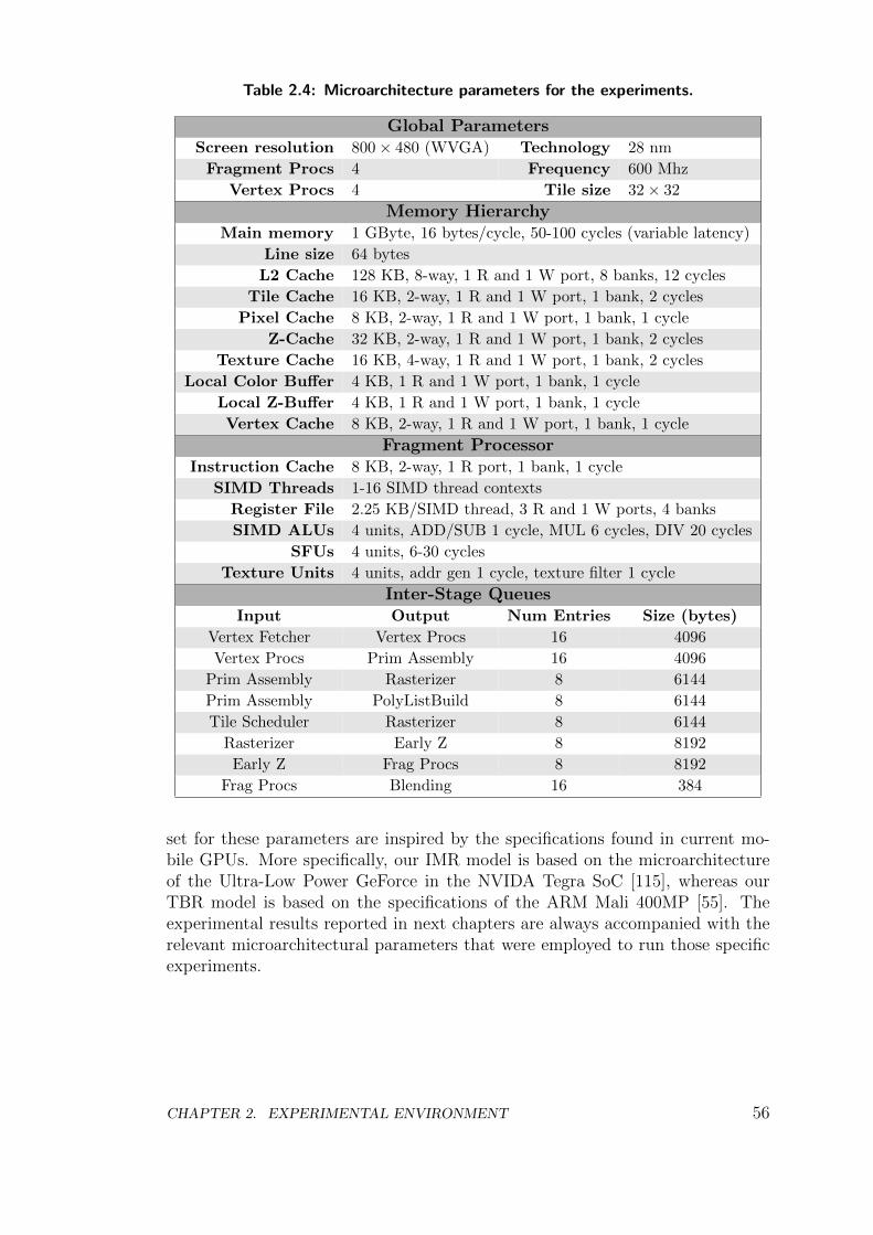
Table 2.4: Microarchitecture parameters for the experiments.
Global ParametersScreen resolution 800 × 480 (WVGA) Technology 28 nm
Fragment Procs 4 Frequency 600 Mhz
Vertex Procs 4 Tile size 32 × 32
Memory HierarchyMain memory 1 GByte, 16 bytes/cycle, 50-100 cycles (variable latency)
Line size 64 bytes
L2 Cache 128 KB, 8-way, 1 R and 1 W port, 8 banks, 12 cycles
Tile Cache 16 KB, 2-way, 1 R and 1 W port, 1 bank, 2 cycles
Pixel Cache 8 KB, 2-way, 1 R and 1 W port, 1 bank, 1 cycle
Z-Cache 32 KB, 2-way, 1 R and 1 W port, 1 bank, 2 cycles
Texture Cache 16 KB, 4-way, 1 R and 1 W port, 1 bank, 2 cycles
Local Color Buffer 4 KB, 1 R and 1 W port, 1 bank, 1 cycle
Local Z-Buffer 4 KB, 1 R and 1 W port, 1 bank, 1 cycle
Vertex Cache 8 KB, 2-way, 1 R and 1 W port, 1 bank, 1 cycle
Fragment ProcessorInstruction Cache 8 KB, 2-way, 1 R port, 1 bank, 1 cycle
SIMD Threads 1-16 SIMD thread contexts
Register File 2.25 KB/SIMD thread, 3 R and 1 W ports, 4 banks
SIMD ALUs 4 units, ADD/SUB 1 cycle, MUL 6 cycles, DIV 20 cycles
SFUs 4 units, 6-30 cycles
Texture Units 4 units, addr gen 1 cycle, texture filter 1 cycle
Inter-Stage QueuesInput Output Num Entries Size (bytes)
Vertex Fetcher Vertex Procs 16 4096
Vertex Procs Prim Assembly 16 4096
Prim Assembly Rasterizer 8 6144
Prim Assembly PolyListBuild 8 6144
Tile Scheduler Rasterizer 8 6144
Rasterizer Early Z 8 8192
Early Z Frag Procs 8 8192
Frag Procs Blending 16 384
set for these parameters are inspired by the specifications found in current mo-bile GPUs. More specifically, our IMR model is based on the microarchitectureof the Ultra-Low Power GeForce in the NVIDA Tegra SoC [115], whereas ourTBR model is based on the specifications of the ARM Mali 400MP [55]. Theexperimental results reported in next chapters are always accompanied with therelevant microarchitectural parameters that were employed to run those specificexperiments.
CHAPTER 2. EXPERIMENTAL ENVIRONMENT 56

Chapter 3
Decoupled Access/ExecuteFragment Processor
In this chapter we address the problem of hiding the memory latency in a mobileGPU. Firstly, we argue that conventional techniques such as aggressive multi-threading or prefetching are effective but not energy efficient. Secondly, we pro-pose a decoupled access/execute-like design for the fragment processors. Finally,we apply our proposal on top of a state-of-the-art mobile GPU and show thatthe end design with just 4 SIMD threads/processor is able to achieve 97% of theperformance of a larger GPU with 16 SIMD threads/processor, while providing20.5% energy savings.
3.1 Memory Latency Tolerance in a Mobile GPU
The fragment processors fetch data from texture memory. Each one of theseprocessors includes a texture cache to speed-up these memory accesses. Texturememory accesses are common operations in graphics workloads and tend to befine-grained and difficult to prefetch [79]. Graphics workloads have large, long-term (inter-frame) texture datasets that are not amenable to caching. Hence,texture caches focus on conserving bandwidth rather than reducing latency [73].
The fragment processing stage is typically one of the main bottlenecks inthe graphics pipeline. As described in the workload characterization provided insection 2.2.2, the GPU has to process millions of fragments per second and shadingeach fragment usually requires multiple texture fetches. A mobile GPU working atWVGA resolution (800×480) and at a modest 30 frames per second has to processat least more than eleven million fragments per second. Since some games demandmore than ten texture fetches per fragment on average (see Table 2.3), this meansthat the texture sampling subsystem has to sustain hundreds of millions of textureaccesses per second. Therefore, the texture sampling is one of the key stages inthe graphics pipeline, as the GPU spends significant amounts of time and energymapping textures on top of the objects.
CHAPTER 3. DECOUPLED ACCESS/EXECUTE FRAGMENT PROCESSOR 57
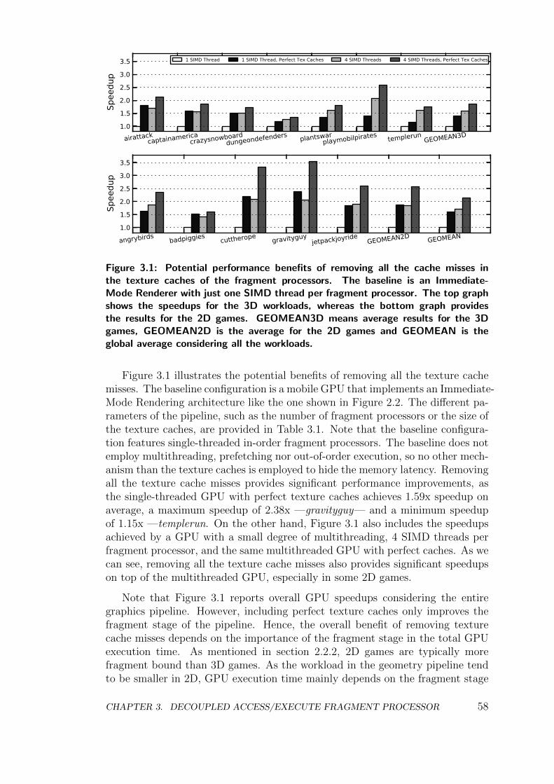
1.0
1.5
2.0
2.5
3.0
3.5
Spee
dup
airattackcaptainamerica
crazysnowboarddungeondefenders plantswar
playmobilpirates templerunGEOMEAN3D
1 SIMD Thread 1 SIMD Thread, Perfect Tex Caches 4 SIMD Threads 4 SIMD Threads, Perfect Tex Caches
1.0
1.5
2.0
2.5
3.0
3.5
Spee
dup
angrybirds badpiggies cuttherope gravityguyjetpackjoyride
GEOMEAN2D GEOMEAN
Figure 3.1: Potential performance benefits of removing all the cache misses inthe texture caches of the fragment processors. The baseline is an Immediate-Mode Renderer with just one SIMD thread per fragment processor. The top graphshows the speedups for the 3D workloads, whereas the bottom graph providesthe results for the 2D games. GEOMEAN3D means average results for the 3Dgames, GEOMEAN2D is the average for the 2D games and GEOMEAN is theglobal average considering all the workloads.
Figure 3.1 illustrates the potential benefits of removing all the texture cachemisses. The baseline configuration is a mobile GPU that implements an Immediate-Mode Rendering architecture like the one shown in Figure 2.2. The different pa-rameters of the pipeline, such as the number of fragment processors or the size ofthe texture caches, are provided in Table 3.1. Note that the baseline configura-tion features single-threaded in-order fragment processors. The baseline does notemploy multithreading, prefetching nor out-of-order execution, so no other mech-anism than the texture caches is employed to hide the memory latency. Removingall the texture cache misses provides significant performance improvements, asthe single-threaded GPU with perfect texture caches achieves 1.59x speedup onaverage, a maximum speedup of 2.38x —gravityguy— and a minimum speedupof 1.15x —templerun. On the other hand, Figure 3.1 also includes the speedupsachieved by a GPU with a small degree of multithreading, 4 SIMD threads perfragment processor, and the same multithreaded GPU with perfect caches. As wecan see, removing all the texture cache misses also provides significant speedupson top of the multithreaded GPU, especially in some 2D games.
Note that Figure 3.1 reports overall GPU speedups considering the entiregraphics pipeline. However, including perfect texture caches only improves thefragment stage of the pipeline. Hence, the overall benefit of removing texturecache misses depends on the importance of the fragment stage in the total GPUexecution time. As mentioned in section 2.2.2, 2D games are typically morefragment bound than 3D games. As the workload in the geometry pipeline tendto be smaller in 2D, GPU execution time mainly depends on the fragment stage
CHAPTER 3. DECOUPLED ACCESS/EXECUTE FRAGMENT PROCESSOR 58
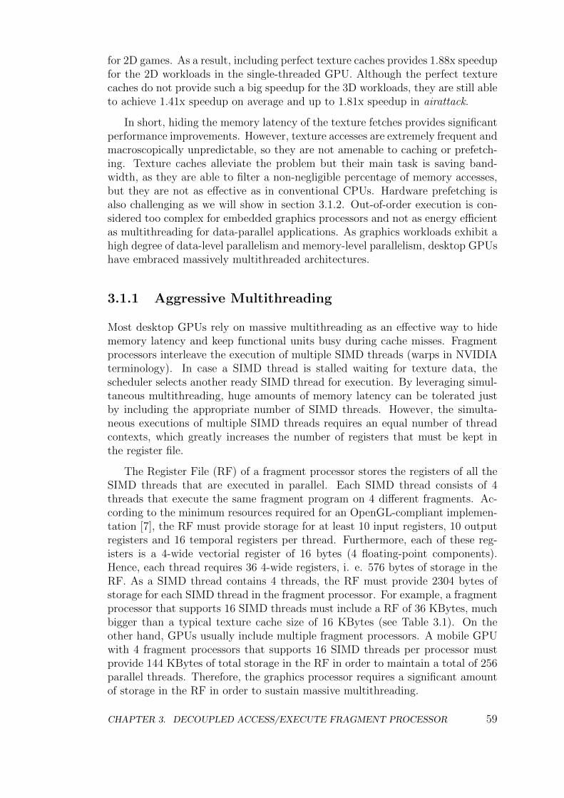
for 2D games. As a result, including perfect texture caches provides 1.88x speedupfor the 2D workloads in the single-threaded GPU. Although the perfect texturecaches do not provide such a big speedup for the 3D workloads, they are still ableto achieve 1.41x speedup on average and up to 1.81x speedup in airattack.
In short, hiding the memory latency of the texture fetches provides significantperformance improvements. However, texture accesses are extremely frequent andmacroscopically unpredictable, so they are not amenable to caching or prefetch-ing. Texture caches alleviate the problem but their main task is saving band-width, as they are able to filter a non-negligible percentage of memory accesses,but they are not as effective as in conventional CPUs. Hardware prefetching isalso challenging as we will show in section 3.1.2. Out-of-order execution is con-sidered too complex for embedded graphics processors and not as energy efficientas multithreading for data-parallel applications. As graphics workloads exhibit ahigh degree of data-level parallelism and memory-level parallelism, desktop GPUshave embraced massively multithreaded architectures.
3.1.1 Aggressive Multithreading
Most desktop GPUs rely on massive multithreading as an effective way to hidememory latency and keep functional units busy during cache misses. Fragmentprocessors interleave the execution of multiple SIMD threads (warps in NVIDIAterminology). In case a SIMD thread is stalled waiting for texture data, thescheduler selects another ready SIMD thread for execution. By leveraging simul-taneous multithreading, huge amounts of memory latency can be tolerated justby including the appropriate number of SIMD threads. However, the simulta-neous executions of multiple SIMD threads requires an equal number of threadcontexts, which greatly increases the number of registers that must be kept inthe register file.
The Register File (RF) of a fragment processor stores the registers of all theSIMD threads that are executed in parallel. Each SIMD thread consists of 4threads that execute the same fragment program on 4 different fragments. Ac-cording to the minimum resources required for an OpenGL-compliant implemen-tation [7], the RF must provide storage for at least 10 input registers, 10 outputregisters and 16 temporal registers per thread. Furthermore, each of these reg-isters is a 4-wide vectorial register of 16 bytes (4 floating-point components).Hence, each thread requires 36 4-wide registers, i. e. 576 bytes of storage in theRF. As a SIMD thread contains 4 threads, the RF must provide 2304 bytes ofstorage for each SIMD thread in the fragment processor. For example, a fragmentprocessor that supports 16 SIMD threads must include a RF of 36 KBytes, muchbigger than a typical texture cache size of 16 KBytes (see Table 3.1). On theother hand, GPUs usually include multiple fragment processors. A mobile GPUwith 4 fragment processors that supports 16 SIMD threads per processor mustprovide 144 KBytes of total storage in the RF in order to maintain a total of 256parallel threads. Therefore, the graphics processor requires a significant amountof storage in the RF in order to sustain massive multithreading.
CHAPTER 3. DECOUPLED ACCESS/EXECUTE FRAGMENT PROCESSOR 59
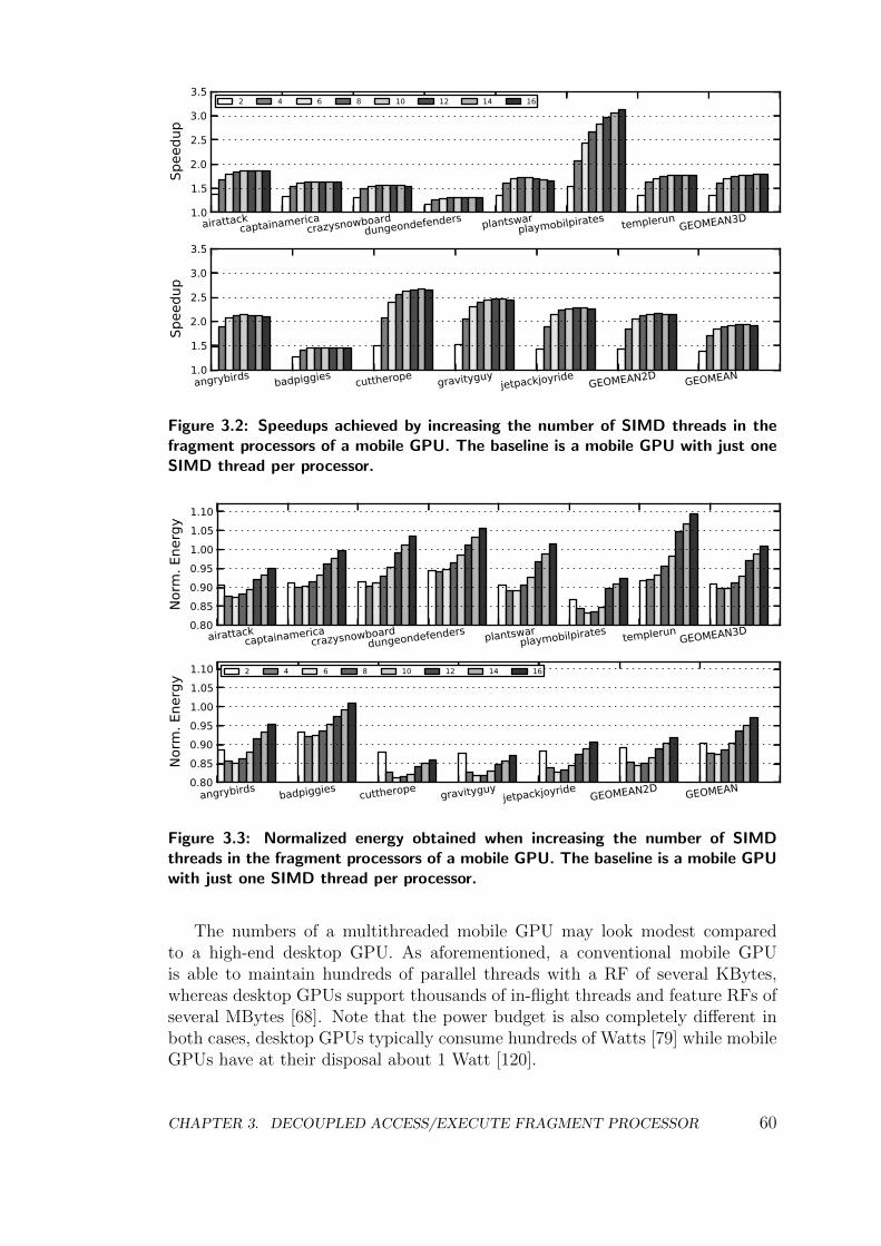
1.0
1.5
2.0
2.5
3.0
3.5
Spee
dup
airattackcaptainamerica
crazysnowboarddungeondefenders plantswar
playmobilpirates templerunGEOMEAN3D
2 4 6 8 10 12 14 16
1.0
1.5
2.0
2.5
3.0
3.5
Spee
dup
angrybirds badpiggies cuttherope gravityguyjetpackjoyride
GEOMEAN2D GEOMEAN
Figure 3.2: Speedups achieved by increasing the number of SIMD threads in thefragment processors of a mobile GPU. The baseline is a mobile GPU with just oneSIMD thread per processor.
0.800.850.900.951.001.051.10
Norm
. Ene
rgy
airattackcaptainamerica
crazysnowboarddungeondefenders plantswar
playmobilpirates templerunGEOMEAN3D
0.800.850.900.951.001.051.10
Norm
. Ene
rgy
angrybirds badpiggies cuttherope gravityguyjetpackjoyride
GEOMEAN2D GEOMEAN
2 4 6 8 10 12 14 16
Figure 3.3: Normalized energy obtained when increasing the number of SIMDthreads in the fragment processors of a mobile GPU. The baseline is a mobile GPUwith just one SIMD thread per processor.
The numbers of a multithreaded mobile GPU may look modest comparedto a high-end desktop GPU. As aforementioned, a conventional mobile GPUis able to maintain hundreds of parallel threads with a RF of several KBytes,whereas desktop GPUs support thousands of in-flight threads and feature RFs ofseveral MBytes [68]. Note that the power budget is also completely different inboth cases, desktop GPUs typically consume hundreds of Watts [79] while mobileGPUs have at their disposal about 1 Watt [120].
CHAPTER 3. DECOUPLED ACCESS/EXECUTE FRAGMENT PROCESSOR 60
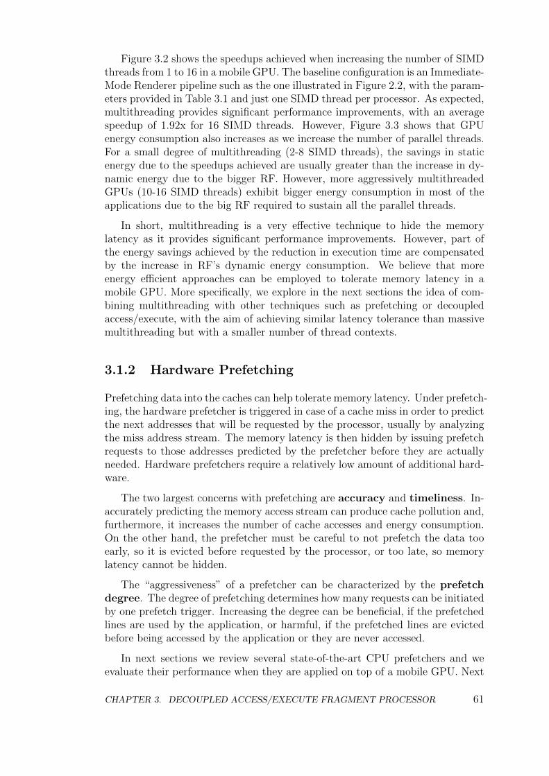
Figure 3.2 shows the speedups achieved when increasing the number of SIMDthreads from 1 to 16 in a mobile GPU. The baseline configuration is an Immediate-Mode Renderer pipeline such as the one illustrated in Figure 2.2, with the param-eters provided in Table 3.1 and just one SIMD thread per processor. As expected,multithreading provides significant performance improvements, with an averagespeedup of 1.92x for 16 SIMD threads. However, Figure 3.3 shows that GPUenergy consumption also increases as we increase the number of parallel threads.For a small degree of multithreading (2-8 SIMD threads), the savings in staticenergy due to the speedups achieved are usually greater than the increase in dy-namic energy due to the bigger RF. However, more aggressively multithreadedGPUs (10-16 SIMD threads) exhibit bigger energy consumption in most of theapplications due to the big RF required to sustain all the parallel threads.
In short, multithreading is a very effective technique to hide the memorylatency as it provides significant performance improvements. However, part ofthe energy savings achieved by the reduction in execution time are compensatedby the increase in RF’s dynamic energy consumption. We believe that moreenergy efficient approaches can be employed to tolerate memory latency in amobile GPU. More specifically, we explore in the next sections the idea of com-bining multithreading with other techniques such as prefetching or decoupledaccess/execute, with the aim of achieving similar latency tolerance than massivemultithreading but with a smaller number of thread contexts.
3.1.2 Hardware Prefetching
Prefetching data into the caches can help tolerate memory latency. Under prefetch-ing, the hardware prefetcher is triggered in case of a cache miss in order to predictthe next addresses that will be requested by the processor, usually by analyzingthe miss address stream. The memory latency is then hidden by issuing prefetchrequests to those addresses predicted by the prefetcher before they are actuallyneeded. Hardware prefetchers require a relatively low amount of additional hard-ware.
The two largest concerns with prefetching are accuracy and timeliness. In-accurately predicting the memory access stream can produce cache pollution and,furthermore, it increases the number of cache accesses and energy consumption.On the other hand, the prefetcher must be careful to not prefetch the data tooearly, so it is evicted before requested by the processor, or too late, so memorylatency cannot be hidden.
The “aggressiveness” of a prefetcher can be characterized by the prefetchdegree. The degree of prefetching determines how many requests can be initiatedby one prefetch trigger. Increasing the degree can be beneficial, if the prefetchedlines are used by the application, or harmful, if the prefetched lines are evictedbefore being accessed by the application or they are never accessed.
In next sections we review several state-of-the-art CPU prefetchers and weevaluate their performance when they are applied on top of a mobile GPU. Next
CHAPTER 3. DECOUPLED ACCESS/EXECUTE FRAGMENT PROCESSOR 61
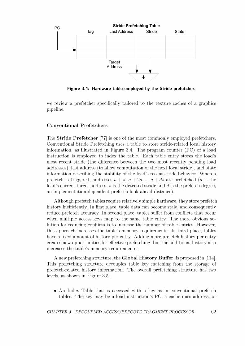
Tag Last Address Stride StatePC
Target Address
+
Stride Prefetching Table
Figure 3.4: Hardware table employed by the Stride prefetcher.
we review a prefetcher specifically tailored to the texture caches of a graphicspipeline.
Conventional Prefetchers
The Stride Prefetcher [77] is one of the most commonly employed prefetchers.Conventional Stride Prefetching uses a table to store stride-related local historyinformation, as illustrated in Figure 3.4. The program counter (PC) of a loadinstruction is employed to index the table. Each table entry stores the load’smost recent stride (the difference between the two most recently pending loadaddresses), last address (to allow computation of the next local stride), and stateinformation describing the stability of the load’s recent stride behavior. When aprefetch is triggered, addresses a + s, a + 2s,..., a + ds are prefetched (a is theload’s current target address, s is the detected stride and d is the prefetch degree,an implementation dependent prefetch look-ahead distance).
Although prefetch tables require relatively simple hardware, they store prefetchhistory inefficiently. In first place, table data can become stale, and consequentlyreduce prefetch accuracy. In second place, tables suffer from conflicts that occurwhen multiple access keys map to the same table entry. The more obvious so-lution for reducing conflicts is to increase the number of table entries. However,this approach increases the table’s memory requirements. In third place, tableshave a fixed amount of history per entry. Adding more prefetch history per entrycreates new opportunities for effective prefetching, but the additional history alsoincreases the table’s memory requirements.
A new prefetching structure, the Global History Buffer, is proposed in [114].This prefetching structure decouples table key matching from the storage ofprefetch-related history information. The overall prefetching structure has twolevels, as shown in Figure 3.5:
• An Index Table that is accessed with a key as in conventional prefetchtables. The key may be a load instruction’s PC, a cache miss address, or
CHAPTER 3. DECOUPLED ACCESS/EXECUTE FRAGMENT PROCESSOR 62
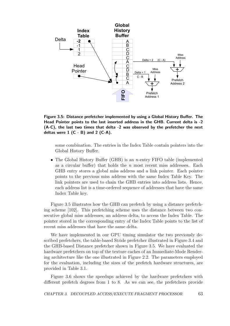
IndexTable
Delta
GlobalHistoryBuffer
PrefetchAddress 1
HeadPointer
FIFO
-2-1 1 2
ABCDCACDBCA +
MissAddress +
PrefetchAddress 2
Delta = 1
C - B
Delta = 2 (C - A)
MissAddress
Figure 3.5: Distance prefetcher implemented by using a Global History Buffer. TheHead Pointer points to the last inserted address in the GHB. Current delta is -2(A-C), the last two times that delta -2 was observed by the prefetcher the nextdeltas were 1 (C - B) and 2 (C-A).
some combination. The entries in the Index Table contain pointers into theGlobal History Buffer.
• The Global History Buffer (GHB) is an n-entry FIFO table (implementedas a circular buffer) that holds the n most recent miss addresses. EachGHB entry stores a global miss address and a link pointer. Each pointerpoints to the previous miss address with the same Index Table Key. Thelink pointers are used to chain the GHB entries into address lists. Hence,each address list is a time-ordered sequence of addresses that have the sameIndex Table key.
Figure 3.5 illustrates how the GHB can prefetch by using a distance prefetch-ing scheme [102]. This prefetching scheme uses the distance between two con-secutive global miss addresses, an address delta, to access the Index Table. Thepointer stored in the corresponding entry of the Index Table points to the list ofrecent miss addresses that have the same delta.
We have implemented in our GPU timing simulator the two previously de-scribed prefetchers, the table-based Stride prefetcher illustrated in Figure 3.4 andthe GHB-based Distance prefetcher shown in Figure 3.5. We have evaluated thehardware prefetchers on top of the texture caches of an Immediate-Mode Render-ing architecture like the one illustrated in Figure 2.2. The parameters employedfor the evaluation, including the sizes of the prefetch hardware structures, areprovided in Table 3.1.
Figure 3.6 shows the speedups achieved by the hardware prefetchers withdifferent prefetch degrees from 1 to 8. As we can see, the prefetchers provide
CHAPTER 3. DECOUPLED ACCESS/EXECUTE FRAGMENT PROCESSOR 63
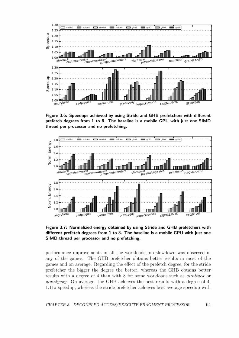
1.001.051.101.151.201.251.30
Spee
dup
airattackcaptainamerica
crazysnowboarddungeondefenders plantswar
playmobilpirates templerunGEOMEAN3D
stride1 stride2 stride4 stride8 ghb1 ghb2 ghb4 ghb8
1.001.051.101.151.201.251.30
Spee
dup
angrybirds badpiggies cuttherope gravityguyjetpackjoyride
GEOMEAN2D GEOMEAN
Figure 3.6: Speedups achieved by using Stride and GHB prefetchers with differentprefetch degrees from 1 to 8. The baseline is a mobile GPU with just one SIMDthread per processor and no prefetching.
1.0
1.2
1.4
1.6
1.8
Norm
. Ene
rgy
airattackcaptainamerica
crazysnowboarddungeondefenders plantswar
playmobilpirates templerunGEOMEAN3D
stride1 stride2 stride4 stride8 ghb1 ghb2 ghb4 ghb8
1.0
1.2
1.4
1.6
1.8
Norm
. Ene
rgy
angrybirds badpiggies cuttherope gravityguyjetpackjoyride
GEOMEAN2D GEOMEAN
Figure 3.7: Normalized energy obtained by using Stride and GHB prefetchers withdifferent prefetch degrees from 1 to 8. The baseline is a mobile GPU with just oneSIMD thread per processor and no prefetching.
performance improvements in all the workloads, no slowdown was observed inany of the games. The GHB prefetcher obtains better results in most of thegames and on average. Regarding the effect of the prefetch degree, for the strideprefetcher the bigger the degree the better, whereas the GHB obtains betterresults with a degree of 4 than with 8 for some workloads such as airattack orgravityguy. On average, the GHB achieves the best results with a degree of 4,1.11x speedup, whereas the stride prefetcher achieves best average speedup with
CHAPTER 3. DECOUPLED ACCESS/EXECUTE FRAGMENT PROCESSOR 64
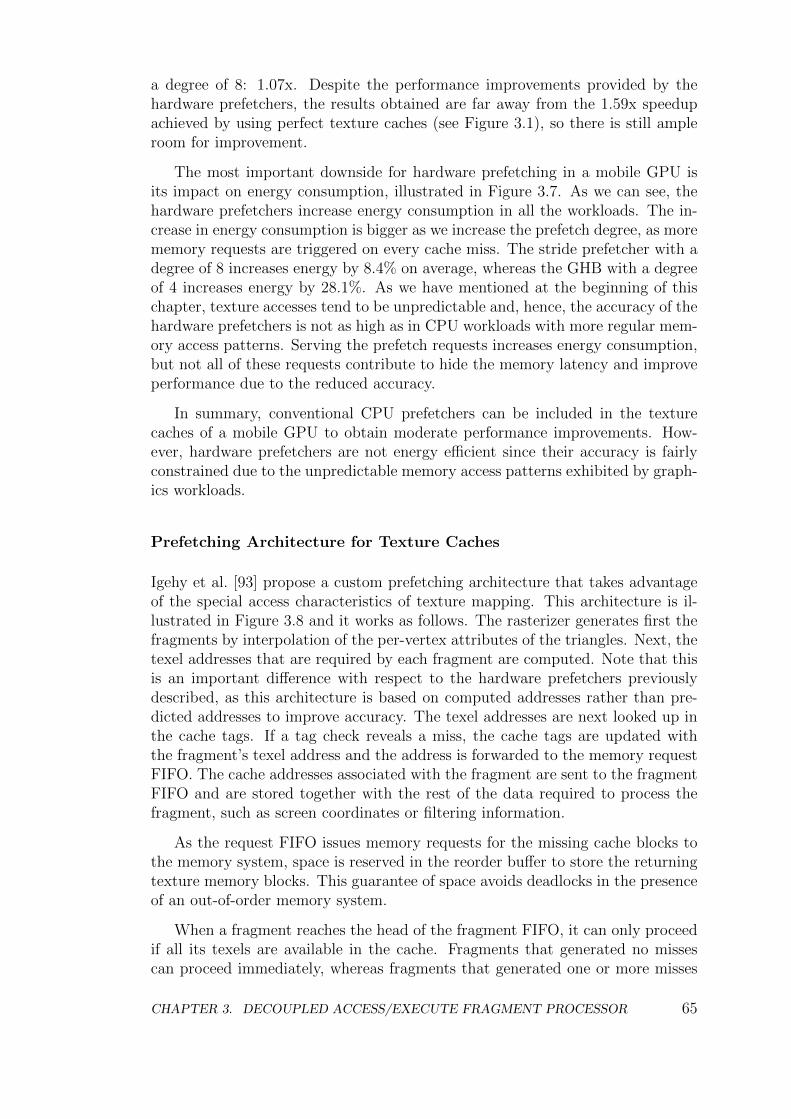
a degree of 8: 1.07x. Despite the performance improvements provided by thehardware prefetchers, the results obtained are far away from the 1.59x speedupachieved by using perfect texture caches (see Figure 3.1), so there is still ampleroom for improvement.
The most important downside for hardware prefetching in a mobile GPU isits impact on energy consumption, illustrated in Figure 3.7. As we can see, thehardware prefetchers increase energy consumption in all the workloads. The in-crease in energy consumption is bigger as we increase the prefetch degree, as morememory requests are triggered on every cache miss. The stride prefetcher with adegree of 8 increases energy by 8.4% on average, whereas the GHB with a degreeof 4 increases energy by 28.1%. As we have mentioned at the beginning of thischapter, texture accesses tend to be unpredictable and, hence, the accuracy of thehardware prefetchers is not as high as in CPU workloads with more regular mem-ory access patterns. Serving the prefetch requests increases energy consumption,but not all of these requests contribute to hide the memory latency and improveperformance due to the reduced accuracy.
In summary, conventional CPU prefetchers can be included in the texturecaches of a mobile GPU to obtain moderate performance improvements. How-ever, hardware prefetchers are not energy efficient since their accuracy is fairlyconstrained due to the unpredictable memory access patterns exhibited by graph-ics workloads.
Prefetching Architecture for Texture Caches
Igehy et al. [93] propose a custom prefetching architecture that takes advantageof the special access characteristics of texture mapping. This architecture is il-lustrated in Figure 3.8 and it works as follows. The rasterizer generates first thefragments by interpolation of the per-vertex attributes of the triangles. Next, thetexel addresses that are required by each fragment are computed. Note that thisis an important difference with respect to the hardware prefetchers previouslydescribed, as this architecture is based on computed addresses rather than pre-dicted addresses to improve accuracy. The texel addresses are next looked up inthe cache tags. If a tag check reveals a miss, the cache tags are updated withthe fragment’s texel address and the address is forwarded to the memory requestFIFO. The cache addresses associated with the fragment are sent to the fragmentFIFO and are stored together with the rest of the data required to process thefragment, such as screen coordinates or filtering information.
As the request FIFO issues memory requests for the missing cache blocks tothe memory system, space is reserved in the reorder buffer to store the returningtexture memory blocks. This guarantee of space avoids deadlocks in the presenceof an out-of-order memory system.
When a fragment reaches the head of the fragment FIFO, it can only proceedif all its texels are available in the cache. Fragments that generated no missescan proceed immediately, whereas fragments that generated one or more misses
CHAPTER 3. DECOUPLED ACCESS/EXECUTE FRAGMENT PROCESSOR 65
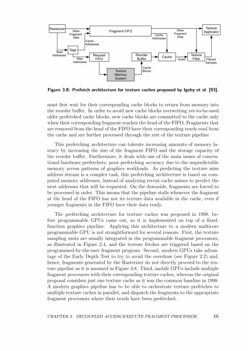
Rasterizer TextureApplicator
TagsTexel
Addresses
OtherFragment
DataCacheAddresses
RequestFIFOMiss
Addresses
TextureMemorySystem
ReorderBuffer
CacheBlocks
Cache
CacheAddresses
TextureFilter
OtherFragment
Data
Texels
Fragment FIFO
FilteredSamples
Figure 3.8: Prefetch architecture for texture caches proposed by Igehy et al. [93].
must first wait for their corresponding cache blocks to return from memory intothe reorder buffer. In order to avoid new cache blocks overwriting yet-to-be-usedolder prefetched cache blocks, new cache blocks are committed to the cache onlywhen their corresponding fragment reaches the head of the FIFO. Fragments thatare removed from the head of the FIFO have their corresponding texels read fromthe cache and are further processed through the rest of the texture pipeline.
This prefetching architecture can tolerate increasing amounts of memory la-tency by increasing the size of the fragment FIFO and the storage capacity ofthe reorder buffer. Furthermore, it deals with one of the main issues of conven-tional hardware prefetchers: poor prefetching accuracy due to the unpredictablememory access patterns of graphics workloads. As predicting the texture missaddress stream is a complex task, this prefetching architecture is based on com-puted memory addresses, instead of analyzing recent cache misses to predict thenext addresses that will be requested. On the downside, fragments are forced tobe processed in order. This means that the pipeline stalls whenever the fragmentat the head of the FIFO has not its texture data available in the cache, even ifyounger fragments in the FIFO have their data ready.
The prefetching architecture for texture caches was proposed in 1998, be-fore programmable GPUs came out, so it is implemented on top of a fixed-function graphics pipeline. Applying this architecture to a modern multicoreprogrammable GPU is not straightforward for several reasons. First, the texturesampling units are usually integrated in the programmable fragment processors,as illustrated in Figure 2.4, and the texture fetches are triggered based on theprogrammed-by-the-user fragment program. Second, modern GPUs take advan-tage of the Early Depth Test to try to avoid the overdraw (see Figure 2.2) and,hence, fragments generated by the Rasterizer do not directly proceed to the tex-ture pipeline as it is assumed in Figure 3.8. Third, mobile GPUs include multiplefragment processors with their corresponding texture caches, whereas the originalproposal considers just one texture cache as it was the common baseline in 1998.A modern graphics pipeline has to be able to orchestrate texture prefetches tomultiple texture caches in parallel, and dispatch the fragments to the appropriatefragment processors where their texels have been prefetched.
CHAPTER 3. DECOUPLED ACCESS/EXECUTE FRAGMENT PROCESSOR 66
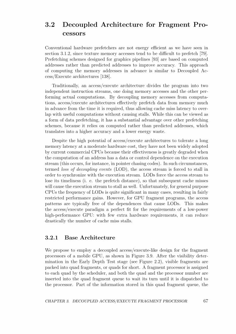
3.2 Decoupled Architecture for Fragment Pro-
cessors
Conventional hardware prefetchers are not energy efficient as we have seen insection 3.1.2, since texture memory accesses tend to be difficult to prefetch [79].Prefetching schemes designed for graphics pipelines [93] are based on computedaddresses rather than predicted addresses to improve accuracy. This approachof computing the memory addresses in advance is similar to Decoupled Ac-cess/Execute architectures [138].
Traditionally, an access/execute architecture divides the program into twoindependent instruction streams, one doing memory accesses and the other per-forming actual computations. By decoupling memory accesses from computa-tions, access/execute architectures effectively prefetch data from memory muchin advance from the time it is required, thus allowing cache miss latency to over-lap with useful computations without causing stalls. While this can be viewed asa form of data prefetching, it has a substantial advantage over other prefetchingschemes, because it relies on computed rather than predicted addresses, whichtranslates into a higher accuracy and a lower energy waste.
Despite the high potential of access/execute architectures to tolerate a longmemory latency at a moderate hardware cost, they have not been widely adoptedby current commercial CPUs because their effectiveness is greatly degraded whenthe computation of an address has a data or control dependence on the executionstream (this occurs, for instance, in pointer chasing codes). In such circumstances,termed loss of decoupling events (LOD), the access stream is forced to stall inorder to synchronize with the execution stream. LODs force the access stream tolose its timeliness (i. e. the prefetch distance), so that subsequent cache misseswill cause the execution stream to stall as well. Unfortunately, for general purposeCPUs the frequency of LODs is quite significant in many cases, resulting in fairlyrestricted performance gains. However, for GPU fragment programs, the accesspatterns are typically free of the dependences that cause LODs. This makesthe access/execute paradigm a perfect fit for the requirements of a low-powerhigh-performance GPU: with few extra hardware requirements, it can reducedrastically the number of cache miss stalls.
3.2.1 Base Architecture
We propose to employ a decoupled access/execute-like design for the fragmentprocessors of a mobile GPU, as shown in Figure 3.9. After the visibility deter-mination in the Early Depth Test stage (see Figure 2.2), visible fragments arepacked into quad fragments, or quads for short. A fragment processor is assignedto each quad by the scheduler, and both the quad and the processor number areinserted into the quad fragment queue to wait its turn until it is dispatched tothe processor. Part of the information stored in this quad fragment queue, the
CHAPTER 3. DECOUPLED ACCESS/EXECUTE FRAGMENT PROCESSOR 67
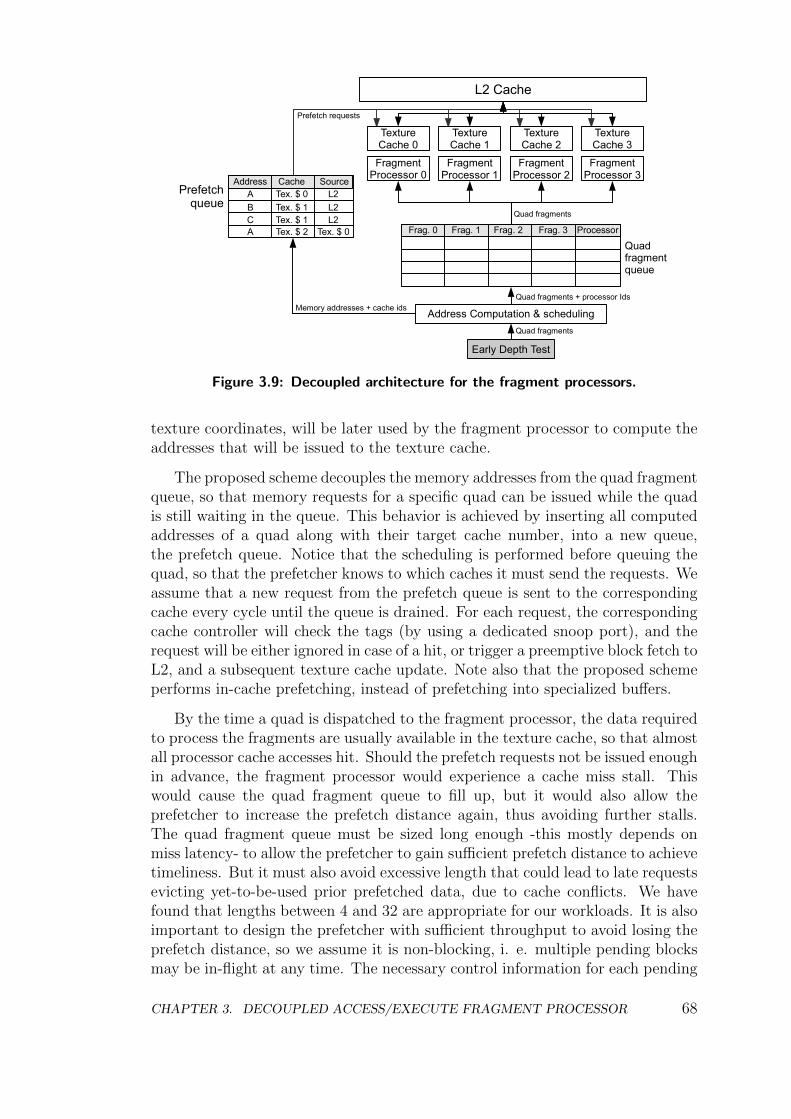
L2 Cache
FragmentProcessor 0
FragmentProcessor 1
Frag. 0 Frag. 1 Frag. 2 Processor
Address Computation & scheduling
Quadfragment queue
Prefetchqueue
Frag. 3
TextureCache 2
FragmentProcessor 2
TextureCache 3
FragmentProcessor 3
TextureCache 0
TextureCache 1
Early Depth Test
A Tex. $ 0
B Tex. $ 1 L2C Tex. $ 1 L2A Tex. $ 2 Tex. $ 0
Quad fragments
Quad fragments + processor Ids Memory addresses + cache ids
Quad fragments
Prefetch requests
Address CacheL2
Source
Figure 3.9: Decoupled architecture for the fragment processors.
texture coordinates, will be later used by the fragment processor to compute theaddresses that will be issued to the texture cache.
The proposed scheme decouples the memory addresses from the quad fragmentqueue, so that memory requests for a specific quad can be issued while the quadis still waiting in the queue. This behavior is achieved by inserting all computedaddresses of a quad along with their target cache number, into a new queue,the prefetch queue. Notice that the scheduling is performed before queuing thequad, so that the prefetcher knows to which caches it must send the requests. Weassume that a new request from the prefetch queue is sent to the correspondingcache every cycle until the queue is drained. For each request, the correspondingcache controller will check the tags (by using a dedicated snoop port), and therequest will be either ignored in case of a hit, or trigger a preemptive block fetch toL2, and a subsequent texture cache update. Note also that the proposed schemeperforms in-cache prefetching, instead of prefetching into specialized buffers.
By the time a quad is dispatched to the fragment processor, the data requiredto process the fragments are usually available in the texture cache, so that almostall processor cache accesses hit. Should the prefetch requests not be issued enoughin advance, the fragment processor would experience a cache miss stall. Thiswould cause the quad fragment queue to fill up, but it would also allow theprefetcher to increase the prefetch distance again, thus avoiding further stalls.The quad fragment queue must be sized long enough -this mostly depends onmiss latency- to allow the prefetcher to gain sufficient prefetch distance to achievetimeliness. But it must also avoid excessive length that could lead to late requestsevicting yet-to-be-used prior prefetched data, due to cache conflicts. We havefound that lengths between 4 and 32 are appropriate for our workloads. It is alsoimportant to design the prefetcher with sufficient throughput to avoid losing theprefetch distance, so we assume it is non-blocking, i. e. multiple pending blocksmay be in-flight at any time. The necessary control information for each pending
CHAPTER 3. DECOUPLED ACCESS/EXECUTE FRAGMENT PROCESSOR 68
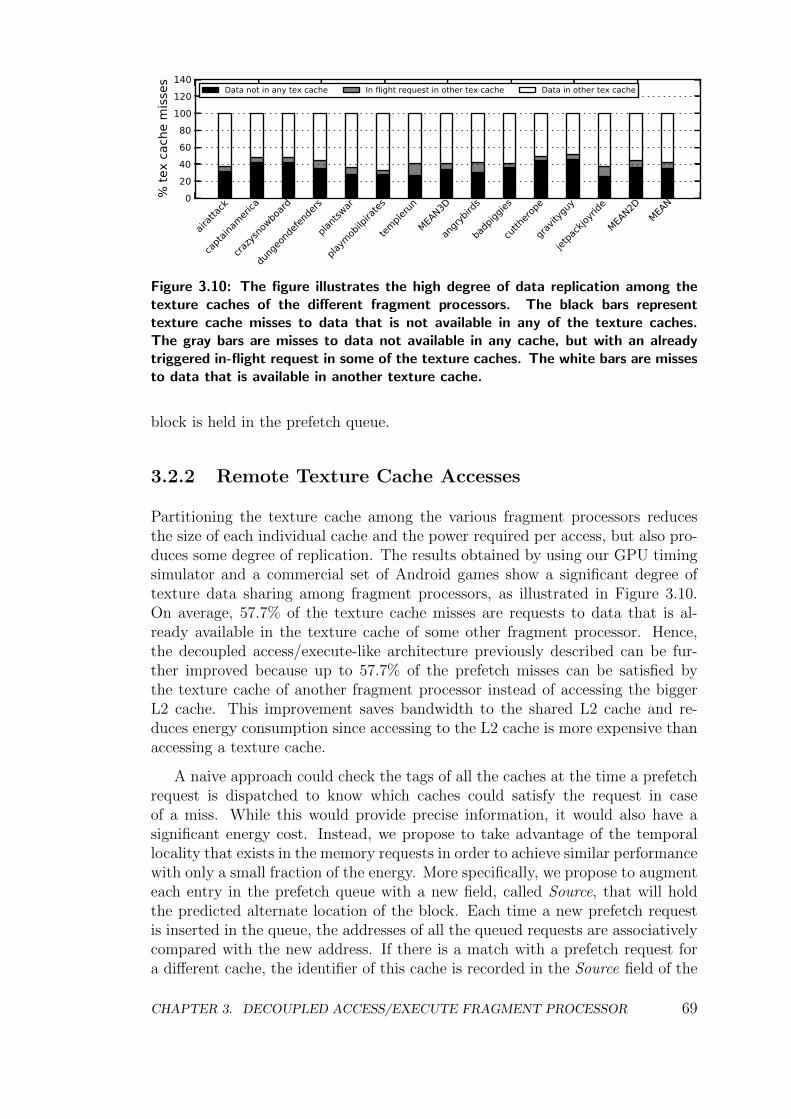
020406080
100120140
% te
x ca
che
mis
ses
airatt
ack
capta
inameri
ca
crazys
nowbo
ard
dung
eond
efend
ers
plants
war
playm
obilp
irates
temple
run
MEAN3D
angry
birds
badp
iggies
cutth
erope
gravit
yguy
jetpa
ckjoy
ride
MEAN2D
MEAN
Data not in any tex cache In flight request in other tex cache Data in other tex cache
Figure 3.10: The figure illustrates the high degree of data replication among thetexture caches of the different fragment processors. The black bars representtexture cache misses to data that is not available in any of the texture caches.The gray bars are misses to data not available in any cache, but with an alreadytriggered in-flight request in some of the texture caches. The white bars are missesto data that is available in another texture cache.
block is held in the prefetch queue.
3.2.2 Remote Texture Cache Accesses
Partitioning the texture cache among the various fragment processors reducesthe size of each individual cache and the power required per access, but also pro-duces some degree of replication. The results obtained by using our GPU timingsimulator and a commercial set of Android games show a significant degree oftexture data sharing among fragment processors, as illustrated in Figure 3.10.On average, 57.7% of the texture cache misses are requests to data that is al-ready available in the texture cache of some other fragment processor. Hence,the decoupled access/execute-like architecture previously described can be fur-ther improved because up to 57.7% of the prefetch misses can be satisfied bythe texture cache of another fragment processor instead of accessing the biggerL2 cache. This improvement saves bandwidth to the shared L2 cache and re-duces energy consumption since accessing to the L2 cache is more expensive thanaccessing a texture cache.
A naive approach could check the tags of all the caches at the time a prefetchrequest is dispatched to know which caches could satisfy the request in caseof a miss. While this would provide precise information, it would also have asignificant energy cost. Instead, we propose to take advantage of the temporallocality that exists in the memory requests in order to achieve similar performancewith only a small fraction of the energy. More specifically, we propose to augmenteach entry in the prefetch queue with a new field, called Source, that will holdthe predicted alternate location of the block. Each time a new prefetch requestis inserted in the queue, the addresses of all the queued requests are associativelycompared with the new address. If there is a match with a prefetch request fora different cache, the identifier of this cache is recorded in the Source field of the
CHAPTER 3. DECOUPLED ACCESS/EXECUTE FRAGMENT PROCESSOR 69
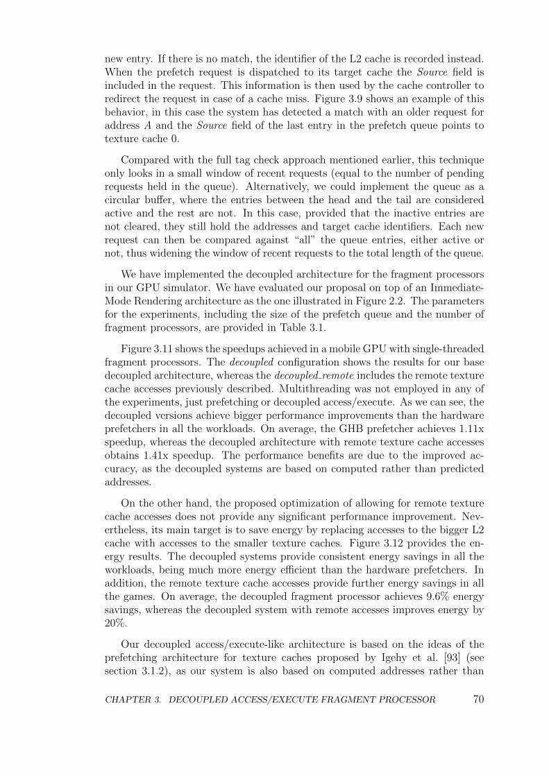
new entry. If there is no match, the identifier of the L2 cache is recorded instead.When the prefetch request is dispatched to its target cache the Source field isincluded in the request. This information is then used by the cache controller toredirect the request in case of a cache miss. Figure 3.9 shows an example of thisbehavior, in this case the system has detected a match with an older request foraddress A and the Source field of the last entry in the prefetch queue points totexture cache 0.
Compared with the full tag check approach mentioned earlier, this techniqueonly looks in a small window of recent requests (equal to the number of pendingrequests held in the queue). Alternatively, we could implement the queue as acircular buffer, where the entries between the head and the tail are consideredactive and the rest are not. In this case, provided that the inactive entries arenot cleared, they still hold the addresses and target cache identifiers. Each newrequest can then be compared against “all” the queue entries, either active ornot, thus widening the window of recent requests to the total length of the queue.
We have implemented the decoupled architecture for the fragment processorsin our GPU simulator. We have evaluated our proposal on top of an Immediate-Mode Rendering architecture as the one illustrated in Figure 2.2. The parametersfor the experiments, including the size of the prefetch queue and the number offragment processors, are provided in Table 3.1.
Figure 3.11 shows the speedups achieved in a mobile GPU with single-threadedfragment processors. The decoupled configuration shows the results for our basedecoupled architecture, whereas the decoupled remote includes the remote texturecache accesses previously described. Multithreading was not employed in any ofthe experiments, just prefetching or decoupled access/execute. As we can see, thedecoupled versions achieve bigger performance improvements than the hardwareprefetchers in all the workloads. On average, the GHB prefetcher achieves 1.11xspeedup, whereas the decoupled architecture with remote texture cache accessesobtains 1.41x speedup. The performance benefits are due to the improved ac-curacy, as the decoupled systems are based on computed rather than predictedaddresses.
On the other hand, the proposed optimization of allowing for remote texturecache accesses does not provide any significant performance improvement. Nev-ertheless, its main target is to save energy by replacing accesses to the bigger L2cache with accesses to the smaller texture caches. Figure 3.12 provides the en-ergy results. The decoupled systems provide consistent energy savings in all theworkloads, being much more energy efficient than the hardware prefetchers. Inaddition, the remote texture cache accesses provide further energy savings in allthe games. On average, the decoupled fragment processor achieves 9.6% energysavings, whereas the decoupled system with remote accesses improves energy by20%.
Our decoupled access/execute-like architecture is based on the ideas of theprefetching architecture for texture caches proposed by Igehy et al. [93] (seesection 3.1.2), as our system is also based on computed addresses rather than
CHAPTER 3. DECOUPLED ACCESS/EXECUTE FRAGMENT PROCESSOR 70
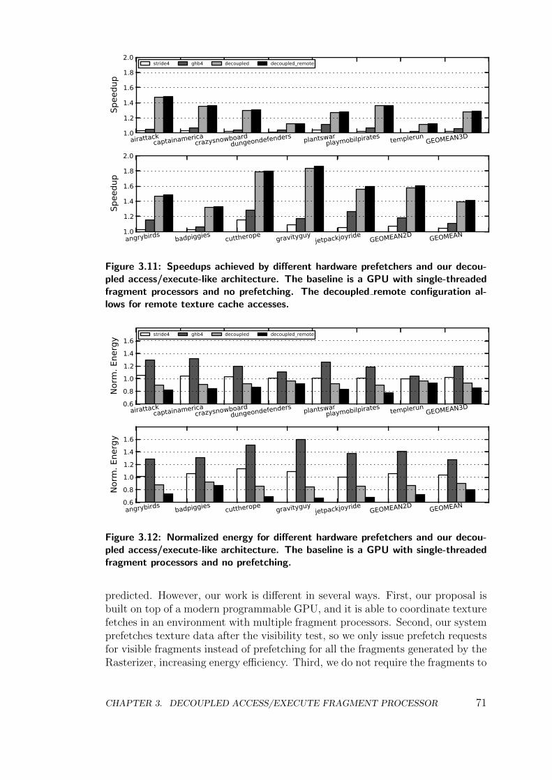
1.0
1.2
1.4
1.6
1.8
2.0
Spee
dup
airattackcaptainamerica
crazysnowboarddungeondefenders plantswar
playmobilpirates templerunGEOMEAN3D
stride4 ghb4 decoupled decoupled_remote
1.0
1.2
1.4
1.6
1.8
2.0
Spee
dup
angrybirds badpiggies cuttherope gravityguyjetpackjoyride
GEOMEAN2D GEOMEAN
Figure 3.11: Speedups achieved by different hardware prefetchers and our decou-pled access/execute-like architecture. The baseline is a GPU with single-threadedfragment processors and no prefetching. The decoupled remote configuration al-lows for remote texture cache accesses.
0.60.81.01.21.41.6
Norm
. Ene
rgy
airattackcaptainamerica
crazysnowboarddungeondefenders plantswar
playmobilpirates templerunGEOMEAN3D
stride4 ghb4 decoupled decoupled_remote
0.60.81.01.21.41.6
Norm
. Ene
rgy
angrybirds badpiggies cuttherope gravityguyjetpackjoyride
GEOMEAN2D GEOMEAN
Figure 3.12: Normalized energy for different hardware prefetchers and our decou-pled access/execute-like architecture. The baseline is a GPU with single-threadedfragment processors and no prefetching.
predicted. However, our work is different in several ways. First, our proposal isbuilt on top of a modern programmable GPU, and it is able to coordinate texturefetches in an environment with multiple fragment processors. Second, our systemprefetches texture data after the visibility test, so we only issue prefetch requestsfor visible fragments instead of prefetching for all the fragments generated by theRasterizer, increasing energy efficiency. Third, we do not require the fragments to
CHAPTER 3. DECOUPLED ACCESS/EXECUTE FRAGMENT PROCESSOR 71
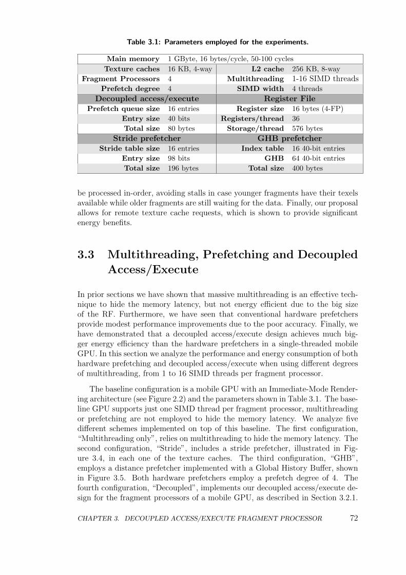
Table 3.1: Parameters employed for the experiments.
Main memory 1 GByte, 16 bytes/cycle, 50-100 cycles
Texture caches 16 KB, 4-way L2 cache 256 KB, 8-way
Fragment Processors 4 Multithreading 1-16 SIMD threadsPrefetch degree 4 SIMD width 4 threads
Decoupled access/execute Register FilePrefetch queue size 16 entries Register size 16 bytes (4-FP)
Entry size 40 bits Registers/thread 36
Total size 80 bytes Storage/thread 576 bytes
Stride prefetcher GHB prefetcherStride table size 16 entries Index table 16 40-bit entries
Entry size 98 bits GHB 64 40-bit entries
Total size 196 bytes Total size 400 bytes
be processed in-order, avoiding stalls in case younger fragments have their texelsavailable while older fragments are still waiting for the data. Finally, our proposalallows for remote texture cache requests, which is shown to provide significantenergy benefits.
3.3 Multithreading, Prefetching and Decoupled
Access/Execute
In prior sections we have shown that massive multithreading is an effective tech-nique to hide the memory latency, but not energy efficient due to the big sizeof the RF. Furthermore, we have seen that conventional hardware prefetchersprovide modest performance improvements due to the poor accuracy. Finally, wehave demonstrated that a decoupled access/execute design achieves much big-ger energy efficiency than the hardware prefetchers in a single-threaded mobileGPU. In this section we analyze the performance and energy consumption of bothhardware prefetching and decoupled access/execute when using different degreesof multithreading, from 1 to 16 SIMD threads per fragment processor.
The baseline configuration is a mobile GPU with an Immediate-Mode Render-ing architecture (see Figure 2.2) and the parameters shown in Table 3.1. The base-line GPU supports just one SIMD thread per fragment processor, multithreadingor prefetching are not employed to hide the memory latency. We analyze fivedifferent schemes implemented on top of this baseline. The first configuration,“Multithreading only”, relies on multithreading to hide the memory latency. Thesecond configuration, “Stride”, includes a stride prefetcher, illustrated in Fig-ure 3.4, in each one of the texture caches. The third configuration, “GHB”,employs a distance prefetcher implemented with a Global History Buffer, shownin Figure 3.5. Both hardware prefetchers employ a prefetch degree of 4. Thefourth configuration, “Decoupled”, implements our decoupled access/execute de-sign for the fragment processors of a mobile GPU, as described in Section 3.2.1.
CHAPTER 3. DECOUPLED ACCESS/EXECUTE FRAGMENT PROCESSOR 72
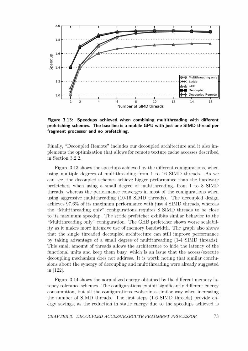
1 2 4 6 8 10 12 14 16Number of SIMD threads
1.0
1.2
1.4
1.6
1.8
2.0
Spee
dup
Multithreading onlyStrideGHBDecoupledDecoupled Remote
Figure 3.13: Speedups achieved when combining multithreading with differentprefetching schemes. The baseline is a mobile GPU with just one SIMD thread perfragment processor and no prefetching.
Finally, “Decoupled Remote” includes our decoupled architecture and it also im-plements the optimization that allows for remote texture cache accesses describedin Section 3.2.2.
Figure 3.13 shows the speedups achieved by the different configurations, whenusing multiple degrees of multithreading from 1 to 16 SIMD threads. As wecan see, the decoupled schemes achieve bigger performance than the hardwareprefetchers when using a small degree of multithreading, from 1 to 8 SIMDthreads, whereas the performance converges in most of the configurations whenusing aggressive multithreading (10-16 SIMD threads). The decoupled designachieves 97.6% of its maximum performance with just 4 SIMD threads, whereasthe “Multithreading only” configurations requires 8 SIMD threads to be closeto its maximum speedup. The stride prefetcher exhibits similar behavior to the“Multithreading only” configuration. The GHB prefetcher shows worse scalabil-ity as it makes more intensive use of memory bandwidth. The graph also showsthat the single threaded decoupled architecture can still improve performanceby taking advantage of a small degree of multithreading (1-4 SIMD threads).This small amount of threads allows the architecture to hide the latency of thefunctional units and keep them busy, which is an issue that the access/executedecoupling mechanism does not address. It is worth noting that similar conclu-sions about the synergy of decoupling and multithreading were already suggestedin [122].
Figure 3.14 shows the normalized energy obtained by the different memory la-tency tolerance schemes. The configurations exhibit significantly different energyconsumption, but all the configurations evolve in a similar way when increasingthe number of SIMD threads. The first steps (1-6 SIMD threads) provide en-ergy savings, as the reduction in static energy due to the speedups achieved is
CHAPTER 3. DECOUPLED ACCESS/EXECUTE FRAGMENT PROCESSOR 73
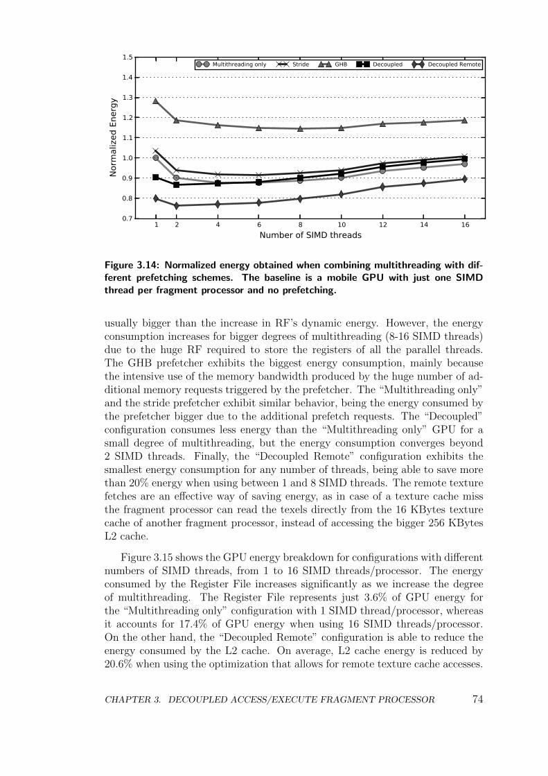
1 2 4 6 8 10 12 14 16Number of SIMD threads
0.7
0.8
0.9
1.0
1.1
1.2
1.3
1.4
1.5
Norm
aliz
ed E
nerg
y
Multithreading only Stride GHB Decoupled Decoupled Remote
Figure 3.14: Normalized energy obtained when combining multithreading with dif-ferent prefetching schemes. The baseline is a mobile GPU with just one SIMDthread per fragment processor and no prefetching.
usually bigger than the increase in RF’s dynamic energy. However, the energyconsumption increases for bigger degrees of multithreading (8-16 SIMD threads)due to the huge RF required to store the registers of all the parallel threads.The GHB prefetcher exhibits the biggest energy consumption, mainly becausethe intensive use of the memory bandwidth produced by the huge number of ad-ditional memory requests triggered by the prefetcher. The “Multithreading only”and the stride prefetcher exhibit similar behavior, being the energy consumed bythe prefetcher bigger due to the additional prefetch requests. The “Decoupled”configuration consumes less energy than the “Multithreading only” GPU for asmall degree of multithreading, but the energy consumption converges beyond2 SIMD threads. Finally, the “Decoupled Remote” configuration exhibits thesmallest energy consumption for any number of threads, being able to save morethan 20% energy when using between 1 and 8 SIMD threads. The remote texturefetches are an effective way of saving energy, as in case of a texture cache missthe fragment processor can read the texels directly from the 16 KBytes texturecache of another fragment processor, instead of accessing the bigger 256 KBytesL2 cache.
Figure 3.15 shows the GPU energy breakdown for configurations with differentnumbers of SIMD threads, from 1 to 16 SIMD threads/processor. The energyconsumed by the Register File increases significantly as we increase the degreeof multithreading. The Register File represents just 3.6% of GPU energy forthe “Multithreading only” configuration with 1 SIMD thread/processor, whereasit accounts for 17.4% of GPU energy when using 16 SIMD threads/processor.On the other hand, the “Decoupled Remote” configuration is able to reduce theenergy consumed by the L2 cache. On average, L2 cache energy is reduced by20.6% when using the optimization that allows for remote texture cache accesses.
CHAPTER 3. DECOUPLED ACCESS/EXECUTE FRAGMENT PROCESSOR 74
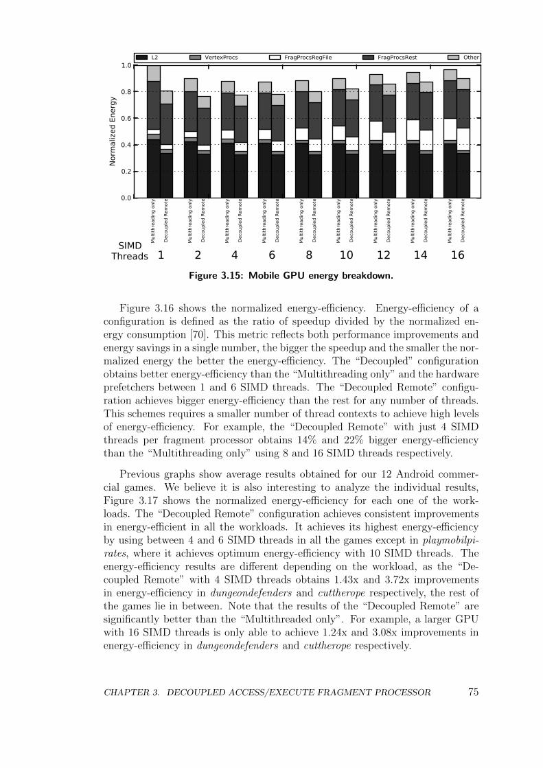
0.0
0.2
0.4
0.6
0.8
1.0
Norm
aliz
ed E
nerg
y
Mul
tithr
eadi
ng o
nly
Deco
uple
d Re
mot
e
1
Mul
tithr
eadi
ng o
nly
Deco
uple
d Re
mot
e
2
Mul
tithr
eadi
ng o
nly
Deco
uple
d Re
mot
e
4M
ultit
hrea
ding
onl
y
Deco
uple
d Re
mot
e
6
Mul
tithr
eadi
ng o
nly
Deco
uple
d Re
mot
e
8
Mul
tithr
eadi
ng o
nly
Deco
uple
d Re
mot
e
10
Mul
tithr
eadi
ng o
nly
Deco
uple
d Re
mot
e
12
Mul
tithr
eadi
ng o
nly
Deco
uple
d Re
mot
e
14
Mul
tithr
eadi
ng o
nly
Deco
uple
d Re
mot
e
16SIMD
Threads
L2 VertexProcs FragProcsRegFile FragProcsRest Other
Figure 3.15: Mobile GPU energy breakdown.
Figure 3.16 shows the normalized energy-efficiency. Energy-efficiency of aconfiguration is defined as the ratio of speedup divided by the normalized en-ergy consumption [70]. This metric reflects both performance improvements andenergy savings in a single number, the bigger the speedup and the smaller the nor-malized energy the better the energy-efficiency. The “Decoupled” configurationobtains better energy-efficiency than the “Multithreading only” and the hardwareprefetchers between 1 and 6 SIMD threads. The “Decoupled Remote” configu-ration achieves bigger energy-efficiency than the rest for any number of threads.This schemes requires a smaller number of thread contexts to achieve high levelsof energy-efficiency. For example, the “Decoupled Remote” with just 4 SIMDthreads per fragment processor obtains 14% and 22% bigger energy-efficiencythan the “Multithreading only” using 8 and 16 SIMD threads respectively.
Previous graphs show average results obtained for our 12 Android commer-cial games. We believe it is also interesting to analyze the individual results,Figure 3.17 shows the normalized energy-efficiency for each one of the work-loads. The “Decoupled Remote” configuration achieves consistent improvementsin energy-efficient in all the workloads. It achieves its highest energy-efficiencyby using between 4 and 6 SIMD threads in all the games except in playmobilpi-rates, where it achieves optimum energy-efficiency with 10 SIMD threads. Theenergy-efficiency results are different depending on the workload, as the “De-coupled Remote” with 4 SIMD threads obtains 1.43x and 3.72x improvementsin energy-efficiency in dungeondefenders and cuttherope respectively, the rest ofthe games lie in between. Note that the results of the “Decoupled Remote” aresignificantly better than the “Multithreaded only”. For example, a larger GPUwith 16 SIMD threads is only able to achieve 1.24x and 3.08x improvements inenergy-efficiency in dungeondefenders and cuttherope respectively.
CHAPTER 3. DECOUPLED ACCESS/EXECUTE FRAGMENT PROCESSOR 75
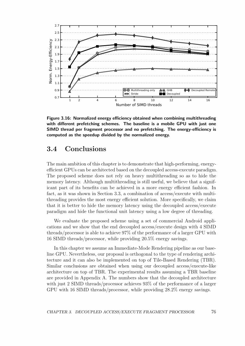
1 2 4 6 8 10 12 14 16Number of SIMD threads
0.7
0.9
1.1
1.3
1.5
1.7
1.9
2.1
2.3
2.5
2.7
Norm
. Ene
rgy-
Effic
ienc
y
Multithreading onlyStride
GHBDecoupled
Decoupled Remote
Figure 3.16: Normalized energy efficiency obtained when combining multithreadingwith different prefetching schemes. The baseline is a mobile GPU with just oneSIMD thread per fragment processor and no prefetching. The energy-efficiency iscomputed as the speedup divided by the normalized energy.
3.4 Conclusions
The main ambition of this chapter is to demonstrate that high-performing, energy-efficient GPUs can be architected based on the decoupled access-execute paradigm.The proposed scheme does not rely on heavy multithreading so as to hide thememory latency. Although multithreading is still useful, we believe that a signif-icant part of its benefits can be achieved in a more energy efficient fashion. Infact, as it was shown in Section 3.3, a combination of access/execute with multi-threading provides the most energy efficient solution. More specifically, we claimthat it is better to hide the memory latency using the decoupled access/executeparadigm and hide the functional unit latency using a low degree of threading.
We evaluate the proposed scheme using a set of commercial Android appli-cations and we show that the end decoupled access/execute design with 4 SIMDthreads/processor is able to achieve 97% of the performance of a larger GPU with16 SIMD threads/processor, while providing 20.5% energy savings.
In this chapter we assume an Immediate-Mode Rendering pipeline as our base-line GPU. Nevertheless, our proposal is orthogonal to the type of rendering archi-tecture and it can also be implemented on top of Tile-Based Rendering (TBR).Similar conclusions are obtained when using our decoupled access/execute-likearchitecture on top of TBR. The experimental results assuming a TBR baselineare provided in Appendix A. The numbers show that the decoupled architecturewith just 2 SIMD threads/processor achieves 93% of the performance of a largerGPU with 16 SIMD threads/processor, while providing 28.2% energy savings.
CHAPTER 3. DECOUPLED ACCESS/EXECUTE FRAGMENT PROCESSOR 76
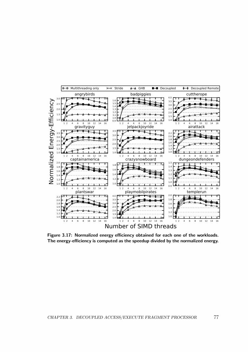
1 2 4 6 8 10 12 14 161.0
1.5
2.0
2.5
3.0angrybirds
Multithreading only Stride GHB Decoupled Decoupled Remote
1 2 4 6 8 10 12 14 160.91.01.11.21.31.41.51.6
badpiggies
1 2 4 6 8 10 12 14 161.01.52.02.53.03.54.0
cuttherope
1 2 4 6 8 10 12 14 161.01.52.02.53.03.5
Norm
aliz
ed E
nerg
y-Ef
ficie
ncy
gravityguy
1 2 4 6 8 10 12 14 161.0
1.5
2.0
2.5
3.0
3.5jetpackjoyride
1 2 4 6 8 10 12 14 161.01.21.41.61.82.02.2
airattack
1 2 4 6 8 10 12 14 16
1.0
1.2
1.4
1.6
1.8
2.0captainamerica
1 2 4 6 8 10 12 14 16
1.0
1.2
1.4
1.6
1.8
crazysnowboard
1 2 4 6 8 10 12 14 160.91.01.11.21.31.41.5
dungeondefenders
1 2 4 6 8 10 12 14 161.01.21.41.61.82.02.2
plantswar
1 2 4 6 8 10 12 14 16
Number of SIMD threads1.01.52.02.53.03.54.0
playmobilpirates
1 2 4 6 8 10 12 14 16
1.0
1.2
1.4
1.6
1.8
2.0templerun
Figure 3.17: Normalized energy efficiency obtained for each one of the workloads.The energy-efficiency is computed as the speedup divided by the normalized energy.
CHAPTER 3. DECOUPLED ACCESS/EXECUTE FRAGMENT PROCESSOR 77

CHAPTER 3. DECOUPLED ACCESS/EXECUTE FRAGMENT PROCESSOR 78
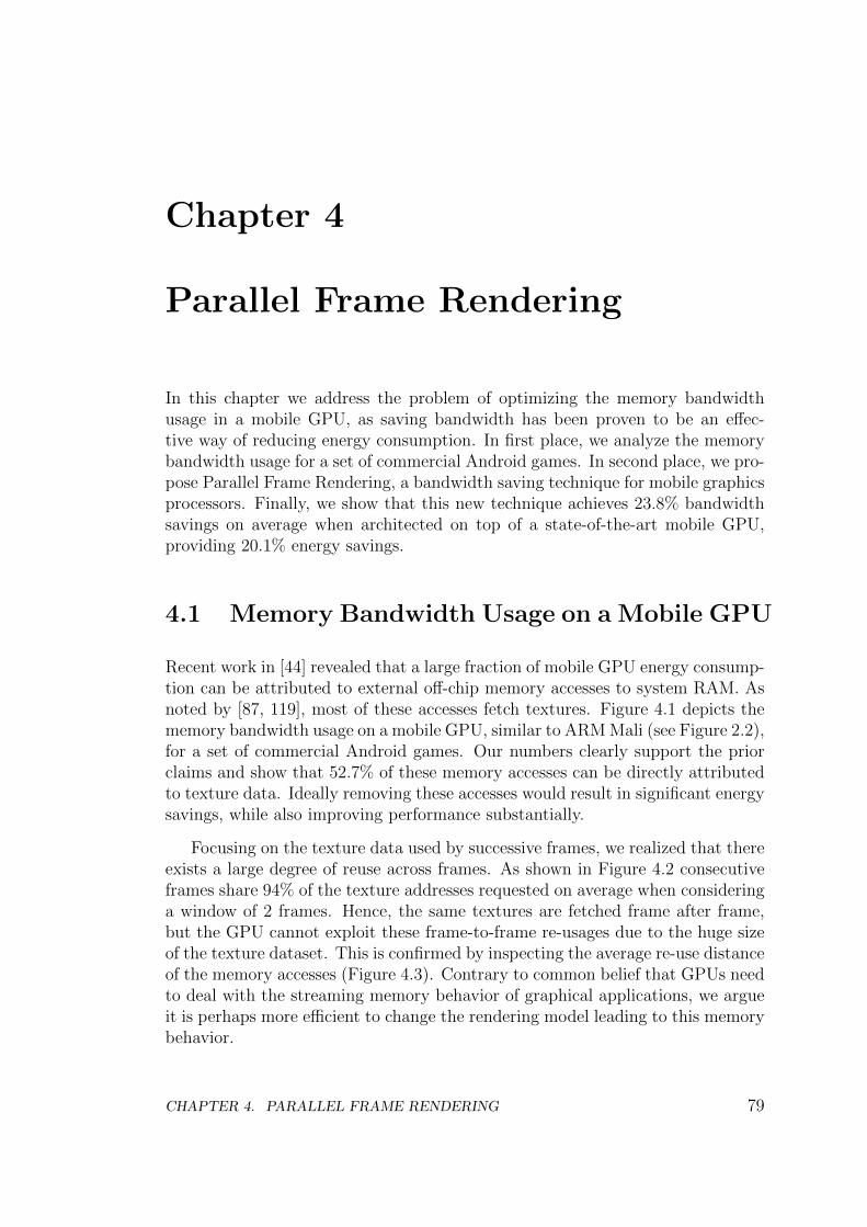
Chapter 4
Parallel Frame Rendering
In this chapter we address the problem of optimizing the memory bandwidthusage in a mobile GPU, as saving bandwidth has been proven to be an effec-tive way of reducing energy consumption. In first place, we analyze the memorybandwidth usage for a set of commercial Android games. In second place, we pro-pose Parallel Frame Rendering, a bandwidth saving technique for mobile graphicsprocessors. Finally, we show that this new technique achieves 23.8% bandwidthsavings on average when architected on top of a state-of-the-art mobile GPU,providing 20.1% energy savings.
4.1 Memory Bandwidth Usage on a Mobile GPU
Recent work in [44] revealed that a large fraction of mobile GPU energy consump-tion can be attributed to external off-chip memory accesses to system RAM. Asnoted by [87, 119], most of these accesses fetch textures. Figure 4.1 depicts thememory bandwidth usage on a mobile GPU, similar to ARM Mali (see Figure 2.2),for a set of commercial Android games. Our numbers clearly support the priorclaims and show that 52.7% of these memory accesses can be directly attributedto texture data. Ideally removing these accesses would result in significant energysavings, while also improving performance substantially.
Focusing on the texture data used by successive frames, we realized that thereexists a large degree of reuse across frames. As shown in Figure 4.2 consecutiveframes share 94% of the texture addresses requested on average when consideringa window of 2 frames. Hence, the same textures are fetched frame after frame,but the GPU cannot exploit these frame-to-frame re-usages due to the huge sizeof the texture dataset. This is confirmed by inspecting the average re-use distanceof the memory accesses (Figure 4.3). Contrary to common belief that GPUs needto deal with the streaming memory behavior of graphical applications, we argueit is perhaps more efficient to change the rendering model leading to this memorybehavior.
CHAPTER 4. PARALLEL FRAME RENDERING 79
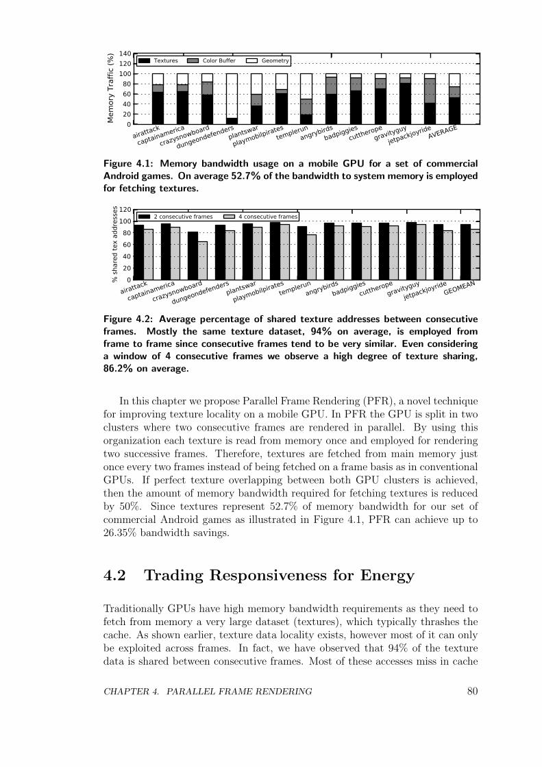
020406080
100120140
Mem
ory
Traf
fic (%
)
airattack
captainamerica
crazysnowboard
dungeondefendersplantswar
playmobilpiratestemplerun
angrybirdsbadpiggies
cuttheropegravityguy
jetpackjoyrideAVERAGE
Textures Color Buffer Geometry
Figure 4.1: Memory bandwidth usage on a mobile GPU for a set of commercialAndroid games. On average 52.7% of the bandwidth to system memory is employedfor fetching textures.
020406080
100120
% s
hare
d te
x ad
dres
ses
airattack
captainamerica
crazysnowboard
dungeondefendersplantswar
playmobilpiratestemplerun
angrybirdsbadpiggies
cuttheropegravityguy
jetpackjoyrideGEOMEAN
2 consecutive frames 4 consecutive frames
Figure 4.2: Average percentage of shared texture addresses between consecutiveframes. Mostly the same texture dataset, 94% on average, is employed fromframe to frame since consecutive frames tend to be very similar. Even consideringa window of 4 consecutive frames we observe a high degree of texture sharing,86.2% on average.
In this chapter we propose Parallel Frame Rendering (PFR), a novel techniquefor improving texture locality on a mobile GPU. In PFR the GPU is split in twoclusters where two consecutive frames are rendered in parallel. By using thisorganization each texture is read from memory once and employed for renderingtwo successive frames. Therefore, textures are fetched from main memory justonce every two frames instead of being fetched on a frame basis as in conventionalGPUs. If perfect texture overlapping between both GPU clusters is achieved,then the amount of memory bandwidth required for fetching textures is reducedby 50%. Since textures represent 52.7% of memory bandwidth for our set ofcommercial Android games as illustrated in Figure 4.1, PFR can achieve up to26.35% bandwidth savings.
4.2 Trading Responsiveness for Energy
Traditionally GPUs have high memory bandwidth requirements as they need tofetch from memory a very large dataset (textures), which typically thrashes thecache. As shown earlier, texture data locality exists, however most of it can onlybe exploited across frames. In fact, we have observed that 94% of the texturedata is shared between consecutive frames. Most of these accesses miss in cache
CHAPTER 4. PARALLEL FRAME RENDERING 80
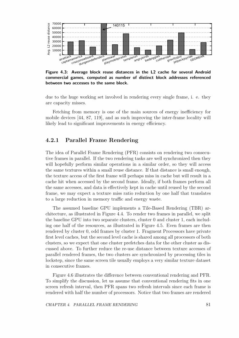
010000200003000040000500006000070000
Avg.
L2
reus
e di
stan
ce
airattack
captainamerica
crazysnowboard
dungeondefendersplantswar
playmobilpiratestemplerun
angrybirdsbadpiggies
cuttheropegravityguy
jetpackjoyrideGEOMEAN
140115
Figure 4.3: Average block reuse distances in the L2 cache for several Androidcommercial games, computed as number of distinct block addresses referencedbetween two accesses to the same block.
due to the huge working set involved in rendering every single frame, i. e. theyare capacity misses.
Fetching from memory is one of the main sources of energy inefficiency formobile devices [44, 87, 119], and as such improving the inter-frame locality willlikely lead to significant improvements in energy efficiency.
4.2.1 Parallel Frame Rendering
The idea of Parallel Frame Rendering (PFR) consists on rendering two consecu-tive frames in parallel. If the two rendering tasks are well synchronized then theywill hopefully perform similar operations in a similar order, so they will accessthe same textures within a small reuse distance. If that distance is small enough,the texture access of the first frame will perhaps miss in cache but will result in acache hit when accessed by the second frame. Ideally, if both frames perform allthe same accesses, and data is effectively kept in cache until reused by the secondframe, we may expect a texture miss ratio reduction by one half that translatesto a large reduction in memory traffic and energy waste.
The assumed baseline GPU implements a Tile-Based Rendering (TBR) ar-chitecture, as illustrated in Figure 4.4. To render two frames in parallel, we splitthe baseline GPU into two separate clusters, cluster 0 and cluster 1, each includ-ing one half of the resources, as illustrated in Figure 4.5. Even frames are thenrendered by cluster 0, odd frames by cluster 1. Fragment Processors have privatefirst level caches, but the second level cache is shared among all processors of bothclusters, so we expect that one cluster prefetches data for the other cluster as dis-cussed above. To further reduce the re-use distance between texture accesses ofparallel rendered frames, the two clusters are synchronized by processing tiles inlockstep, since the same screen tile usually employs a very similar texture datasetin consecutive frames.
Figure 4.6 illustrates the difference between conventional rendering and PFR.To simplify the discussion, let us assume that conventional rendering fits in onescreen refresh interval, then PFR spans two refresh intervals since each frame isrendered with half the number of processors. Notice that two frames are rendered
CHAPTER 4. PARALLEL FRAME RENDERING 81
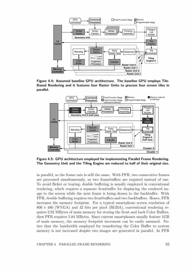
Raster Unit 3Raster Unit 2
Raster Unit 1Raster Unit 0
Fragment Processor
Geometry Unit
GPUcommand
CommandProcessor
MemoryController
VertexFetcher
VertexCache
PrimitiveAssembly
TileCache
PolygonList
Builder
TileScheduler
TilingEngine 0
Memory
Programmable StageFixed-Function Stage
RasterizerEarlyDepth Test
Z-BufferColorBuffer
TextureCache
ALULoad/Store
Blending
L2Cache
VertexProcessor
Figure 4.4: Assumed baseline GPU architecture. The baseline GPU employs Tile-Based Rendering and it features four Raster Units to process four screen tiles inparallel.
Cluster 1Cluster 0
Raster Unit 1Raster Unit 0
Fragment Processor
Geometry Unit 0 (half size)
GPUcommand
CommandProcessor
MemoryController
VertexFetcher
VertexCache
PrimitiveAssembly
TileCache
PolygonList
Builder
TileScheduler
TilingEngine 0(half size)
Memory
Programmable StageFixed-Function Stage
RasterizerEarlyDepth Test
Z-BufferColorBuffer
TextureCache
ALULoad/Store
Blending
L2Cache
VertexProcessor
Fixed-Function Stagereduced to half size
Memory reduced to half size
Figure 4.5: GPU architecture employed for implementing Parallel Frame Rendering.The Geometry Unit and the Tiling Engine are reduced to half of their original size.
in parallel, so the frame rate is still the same. With PFR, two consecutive framesare processed simultaneously, so two framebuffers are required instead of one.To avoid flicker or tearing, double buffering is usually employed in conventionalrendering, which requires a separate frontbuffer for displaying the rendered im-age to the screen while the next frame is being drawn to the backbuffer. WithPFR, double buffering requires two frontbuffers and two backbuffers. Hence, PFRincreases the memory footprint. For a typical smartphone screen resolution of800 × 480 (WVGA) and 32 bits per pixel (RGBA), conventional rendering re-quires 2.92 MBytes of main memory for storing the front and back Color Buffers,then PFR requires 5.84 MBytes. Since current smartphones usually feature 1GBof main memory, the memory footprint increment can be easily assumed. No-tice that the bandwidth employed for transferring the Color Buffer to systemmemory is not increased despite two images are generated in parallel. In PFR
CHAPTER 4. PARALLEL FRAME RENDERING 82
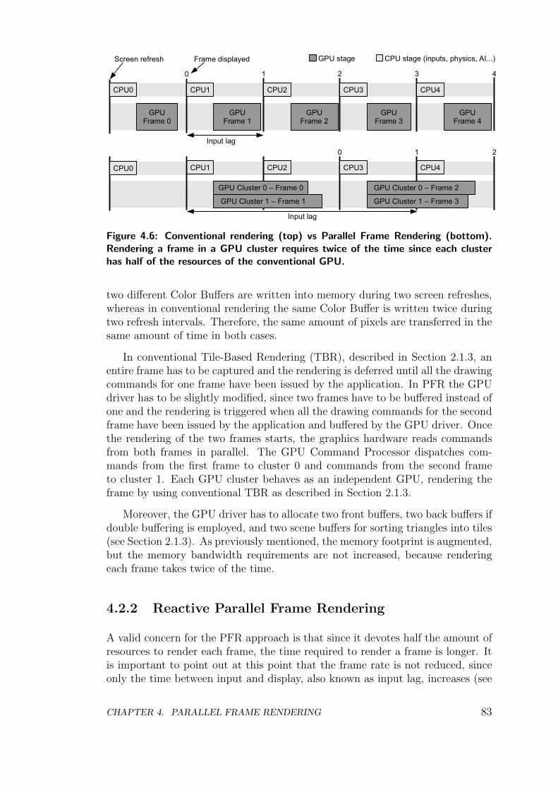
CPU0
GPUFrame 0
CPU1
GPUFrame 1
CPU2
GPUFrame 2
CPU0 CPU1 CPU2
GPU Cluster 0 – Frame 0
GPU Cluster 1 – Frame 1
CPU3
GPUFrame 3
CPU4
GPUFrame 4
CPU3 CPU4
GPU Cluster 0 – Frame 2
GPU Cluster 1 – Frame 3
0 1 2 3 4
0 1 2
Input lag
Input lag
Screen refresh CPU stage (inputs, physics, AI...)GPU stageFrame displayed
Figure 4.6: Conventional rendering (top) vs Parallel Frame Rendering (bottom).Rendering a frame in a GPU cluster requires twice of the time since each clusterhas half of the resources of the conventional GPU.
two different Color Buffers are written into memory during two screen refreshes,whereas in conventional rendering the same Color Buffer is written twice duringtwo refresh intervals. Therefore, the same amount of pixels are transferred in thesame amount of time in both cases.
In conventional Tile-Based Rendering (TBR), described in Section 2.1.3, anentire frame has to be captured and the rendering is deferred until all the drawingcommands for one frame have been issued by the application. In PFR the GPUdriver has to be slightly modified, since two frames have to be buffered instead ofone and the rendering is triggered when all the drawing commands for the secondframe have been issued by the application and buffered by the GPU driver. Oncethe rendering of the two frames starts, the graphics hardware reads commandsfrom both frames in parallel. The GPU Command Processor dispatches com-mands from the first frame to cluster 0 and commands from the second frameto cluster 1. Each GPU cluster behaves as an independent GPU, rendering theframe by using conventional TBR as described in Section 2.1.3.
Moreover, the GPU driver has to allocate two front buffers, two back buffers ifdouble buffering is employed, and two scene buffers for sorting triangles into tiles(see Section 2.1.3). As previously mentioned, the memory footprint is augmented,but the memory bandwidth requirements are not increased, because renderingeach frame takes twice of the time.
4.2.2 Reactive Parallel Frame Rendering
A valid concern for the PFR approach is that since it devotes half the amount ofresources to render each frame, the time required to render a frame is longer. Itis important to point out at this point that the frame rate is not reduced, sinceonly the time between input and display, also known as input lag, increases (see
CHAPTER 4. PARALLEL FRAME RENDERING 83
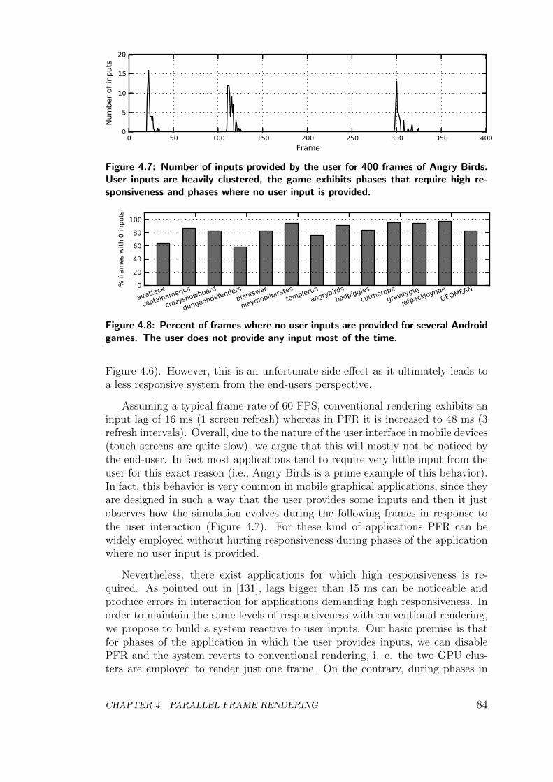
0 50 100 150 200 250 300 350 400Frame
0
5
10
15
20
Num
ber o
f inp
uts
Figure 4.7: Number of inputs provided by the user for 400 frames of Angry Birds.User inputs are heavily clustered, the game exhibits phases that require high re-sponsiveness and phases where no user input is provided.
0
20
40
60
80
100
% fr
ames
with
0 in
puts
airattack
captainamerica
crazysnowboard
dungeondefendersplantswar
playmobilpiratestemplerun
angrybirdsbadpiggies
cuttheropegravityguy
jetpackjoyrideGEOMEAN
Figure 4.8: Percent of frames where no user inputs are provided for several Androidgames. The user does not provide any input most of the time.
Figure 4.6). However, this is an unfortunate side-effect as it ultimately leads toa less responsive system from the end-users perspective.
Assuming a typical frame rate of 60 FPS, conventional rendering exhibits aninput lag of 16 ms (1 screen refresh) whereas in PFR it is increased to 48 ms (3refresh intervals). Overall, due to the nature of the user interface in mobile devices(touch screens are quite slow), we argue that this will mostly not be noticed bythe end-user. In fact most applications tend to require very little input from theuser for this exact reason (i.e., Angry Birds is a prime example of this behavior).In fact, this behavior is very common in mobile graphical applications, since theyare designed in such a way that the user provides some inputs and then it justobserves how the simulation evolves during the following frames in response tothe user interaction (Figure 4.7). For these kind of applications PFR can bewidely employed without hurting responsiveness during phases of the applicationwhere no user input is provided.
Nevertheless, there exist applications for which high responsiveness is re-quired. As pointed out in [131], lags bigger than 15 ms can be noticeable andproduce errors in interaction for applications demanding high responsiveness. Inorder to maintain the same levels of responsiveness with conventional rendering,we propose to build a system reactive to user inputs. Our basic premise is thatfor phases of the application in which the user provides inputs, we can disablePFR and the system reverts to conventional rendering, i. e. the two GPU clus-ters are employed to render just one frame. On the contrary, during phases in
CHAPTER 4. PARALLEL FRAME RENDERING 84
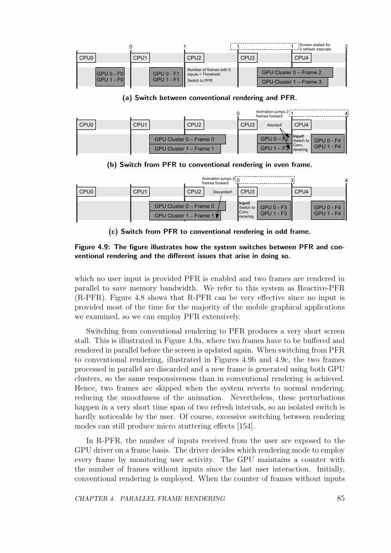
CPU0
GPU 0 - F0GPU 1 - F0
CPU1
GPU 0 - F1GPU 1 - F1
CPU2 CPU3 CPU4
0 1 1 1 2
Number of frames with 0 inputs > Threshold
Swtich to PFR
GPU Cluster 0 – Frame 2
GPU Cluster 1 – Frame 3
Screen stalled for 2 refresh intervals
(a) Switch between conventional rendering and PFR.
CPU0 CPU1 CPU2 CPU3 CPU4
0 1 4
Input!Switch toConv.renering
GPU Cluster 0 – Frame 0
GPU Cluster 1 – Frame 1
Animation jumps 2frames forward
GPU 0 - F4GPU 1 - F4
GPU 0 – F2
GPU 1 – F3
Aborted!
(b) Switch from PFR to conventional rendering in even frame.
CPU0 CPU1 CPU2 CPU3 CPU4
0 3 4
Input!Switch toConv.renering
GPU Cluster 0 – Frame 0
GPU Cluster 1 – Frame 1
Animation jumps 2frames forward
GPU 0 - F4GPU 1 - F4
Discarded!
GPU 0 - F3GPU 1 - F3
(c) Switch from PFR to conventional rendering in odd frame.
Figure 4.9: The figure illustrates how the system switches between PFR and con-ventional rendering and the different issues that arise in doing so.
which no user input is provided PFR is enabled and two frames are rendered inparallel to save memory bandwidth. We refer to this system as Reactive-PFR(R-PFR). Figure 4.8 shows that R-PFR can be very effective since no input isprovided most of the time for the majority of the mobile graphical applicationswe examined, so we can employ PFR extensively.
Switching from conventional rendering to PFR produces a very short screenstall. This is illustrated in Figure 4.9a, where two frames have to be buffered andrendered in parallel before the screen is updated again. When switching from PFRto conventional rendering, illustrated in Figures 4.9b and 4.9c, the two framesprocessed in parallel are discarded and a new frame is generated using both GPUclusters, so the same responsiveness than in conventional rendering is achieved.Hence, two frames are skipped when the system reverts to normal rendering,reducing the smoothness of the animation. Nevertheless, these perturbationshappen in a very short time span of two refresh intervals, so an isolated switch ishardly noticeable by the user. Of course, excessive switching between renderingmodes can still produce micro stuttering effects [154].
In R-PFR, the number of inputs received from the user are exposed to theGPU driver on a frame basis. The driver decides which rendering mode to employevery frame by monitoring user activity. The GPU maintains a counter withthe number of frames without inputs since the last user interaction. Initially,conventional rendering is employed. When the counter of frames without inputs
CHAPTER 4. PARALLEL FRAME RENDERING 85
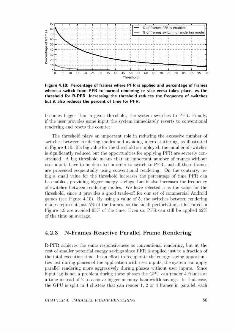
0 5 10 15 20 25 30 35 40 45 50 55 60 65 70 75 80 85 90 95 100Threshold
0102030405060708090
Perc
enta
ge o
f fra
mes
% of frames PFR is enabled% of frames switching rendering mode
Figure 4.10: Percentage of frames where PFR is applied and percentage of frameswhere a switch from PFR to normal rendering or vice versa takes place, vs thethreshold for R-PFR. Increasing the threshold reduces the frequency of switchesbut it also reduces the percent of time for PFR.
becomes bigger than a given threshold, the system switches to PFR. Finally,if the user provides some input the system immediately reverts to conventionalrendering and resets the counter.
The threshold plays an important role in reducing the excessive number ofswitches between rendering modes and avoiding micro stuttering, as illustratedin Figure 4.10. If a big value for the threshold is employed, the number of switchesis significantly reduced but the opportunities for applying PFR are severely con-strained. A big threshold means that an important number of frames withoutuser inputs have to be detected in order to switch to PFR, and all these framesare processed sequentially using conventional rendering. On the contrary, us-ing a small value for the threshold increases the percentage of time PFR canbe enabled, providing bigger energy savings, but it also increases the frequencyof switches between rendering modes. We have selected 5 as the value for thethreshold, since it provides a good trade-off for our set of commercial Androidgames (see Figure 4.10). By using a value of 5, the switches between renderingmodes represent just 5% of the frames, so the small perturbations illustrated inFigure 4.9 are avoided 95% of the time. Even so, PFR can still be applied 62%of the time on average.
4.2.3 N-Frames Reactive Parallel Frame Rendering
R-PFR achieves the same responsiveness as conventional rendering, but at thecost of smaller potential energy savings since PFR is applied just to a fraction ofthe total execution time. In an effort to recuperate the energy saving opportuni-ties lost during phases of the application with user inputs, the system can applyparallel rendering more aggressively during phases without user inputs. Sinceinput lag is not a problem during these phases the GPU can render 4 frames ata time instead of 2 to achieve bigger memory bandwidth savings. In that case,the GPU is split in 4 clusters that can render 1, 2 or 4 frames in parallel, each
CHAPTER 4. PARALLEL FRAME RENDERING 86
cluster having 25% of the resources of the baseline GPU. Initially, conventionalrendering is employed so the 4 GPU clusters are used to render one frame. Whenthe number of frames without inputs is bigger than a given threshold, T1, theGPU driver switches to PFR so 2 GPU clusters are used to render odd framesand the other 2 clusters process even frames. If the number of frames withoutinputs becomes bigger than another threshold, T2, then each GPU cluster rendersa different frame so a total of 4 frames are processed in parallel. Finally, as inR-PFR, if the user provides some input the system immediately reverts to con-ventional rendering, so responsiveness is not reduced. We refer to this techniqueas N-Frames Reactive PFR (NR-PFR).
The thresholds T1 and T2 are set to 5 and 10 respectively, since we foundthese values provide a good trade-off between the number of switches and thepercentage of time PFR is applied for our set of Android applications.
Note that 4 consecutive frames still exhibit a high degree of texture similarity,as shown in Figure 4.2. Ideally, if the 4 frames processed in parallel perform allthe same texture accesses within a short time span, up to 75% memory bandwidthsavings for texture fetching can be achieved.
4.2.4 Delay Randomly Parallel Frame Rendering
PFR delays user inputs in all the frames to achieve big memory bandwidth sav-ings. R-PFR and NR-PFR do not delay any of the user inputs to achieve highresponsiveness, at the cost of smaller bandwidth savings. Between these two ex-tremes, a system can delay just a given percentage of the user inputs in order totrade responsiveness for memory bandwidth savings. We refer to this system asDelay Randomly PFR (DRPFR).
The behavior of DR-PFR is very similar to R-PFR, but when the GPU driverdetects user inputs the system does not always revert immediately to conventionalrendering. Instead, a random number between 0 and 100 is generated and thesystem only switches to normal rendering if the random number is bigger than P ,where P is the maximum percentage of frames where user inputs are allowed tobe delayed. The bigger the value of P , the bigger the memory bandwidth savingsbut the smaller the responsiveness. The value of P can be set, for instance,depending on user preferences. It can also be set depending on the batterylevel, so it is dynamically increased as the battery level decreases in order toextend the use-time per battery charge. The frames where the inputs are delayedare randomly distributed to try to reduce the impact on user interaction, sincerandom distortions are usually harder to perceive by the user than distortionsthat are very localized.
CHAPTER 4. PARALLEL FRAME RENDERING 87
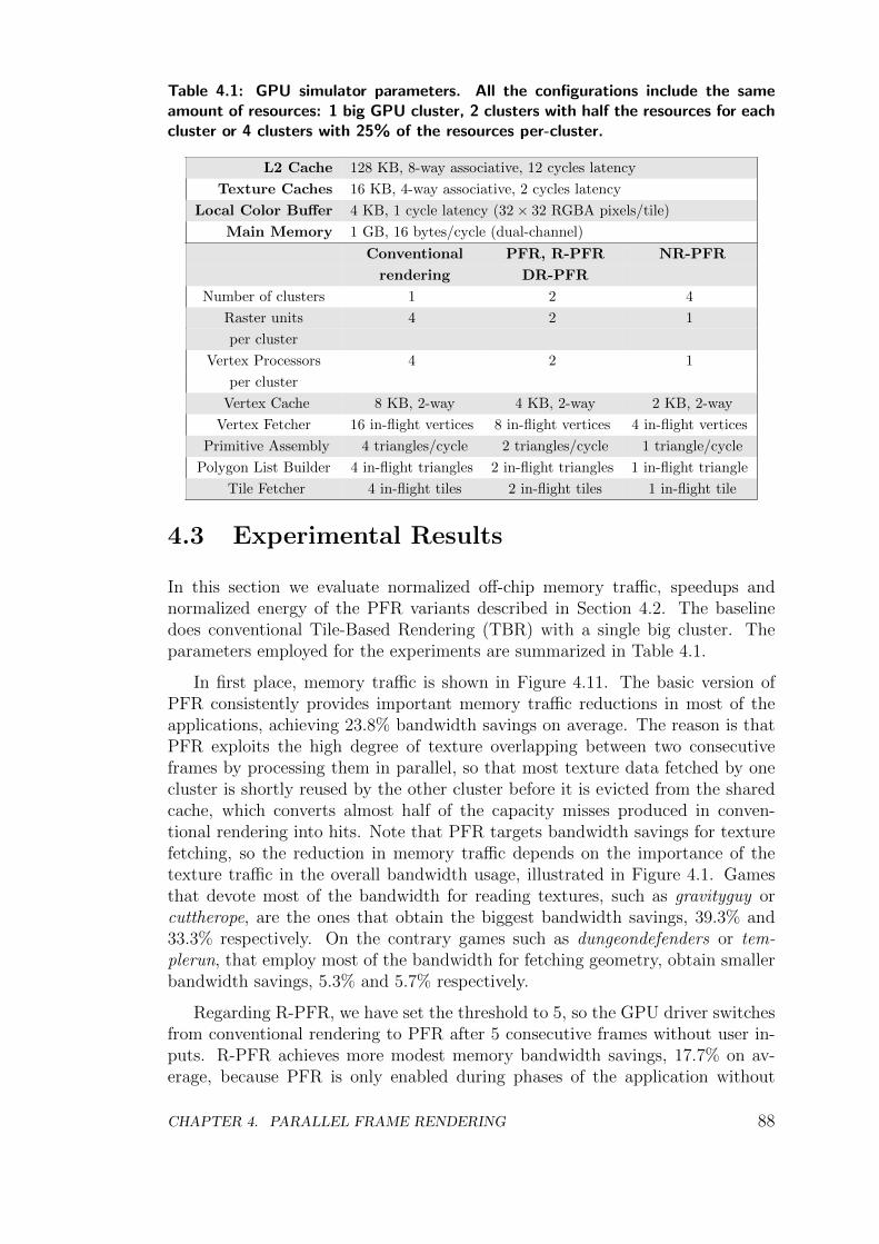
Table 4.1: GPU simulator parameters. All the configurations include the sameamount of resources: 1 big GPU cluster, 2 clusters with half the resources for eachcluster or 4 clusters with 25% of the resources per-cluster.
L2 Cache 128 KB, 8-way associative, 12 cycles latency
Texture Caches 16 KB, 4-way associative, 2 cycles latency
Local Color Buffer 4 KB, 1 cycle latency (32 × 32 RGBA pixels/tile)
Main Memory 1 GB, 16 bytes/cycle (dual-channel)
Conventional PFR, R-PFR NR-PFR
rendering DR-PFR
Number of clusters 1 2 4
Raster units 4 2 1
per cluster
Vertex Processors 4 2 1
per cluster
Vertex Cache 8 KB, 2-way 4 KB, 2-way 2 KB, 2-way
Vertex Fetcher 16 in-flight vertices 8 in-flight vertices 4 in-flight vertices
Primitive Assembly 4 triangles/cycle 2 triangles/cycle 1 triangle/cycle
Polygon List Builder 4 in-flight triangles 2 in-flight triangles 1 in-flight triangle
Tile Fetcher 4 in-flight tiles 2 in-flight tiles 1 in-flight tile
4.3 Experimental Results
In this section we evaluate normalized off-chip memory traffic, speedups andnormalized energy of the PFR variants described in Section 4.2. The baselinedoes conventional Tile-Based Rendering (TBR) with a single big cluster. Theparameters employed for the experiments are summarized in Table 4.1.
In first place, memory traffic is shown in Figure 4.11. The basic version ofPFR consistently provides important memory traffic reductions in most of theapplications, achieving 23.8% bandwidth savings on average. The reason is thatPFR exploits the high degree of texture overlapping between two consecutiveframes by processing them in parallel, so that most texture data fetched by onecluster is shortly reused by the other cluster before it is evicted from the sharedcache, which converts almost half of the capacity misses produced in conven-tional rendering into hits. Note that PFR targets bandwidth savings for texturefetching, so the reduction in memory traffic depends on the importance of thetexture traffic in the overall bandwidth usage, illustrated in Figure 4.1. Gamesthat devote most of the bandwidth for reading textures, such as gravityguy orcuttherope, are the ones that obtain the biggest bandwidth savings, 39.3% and33.3% respectively. On the contrary games such as dungeondefenders or tem-plerun, that employ most of the bandwidth for fetching geometry, obtain smallerbandwidth savings, 5.3% and 5.7% respectively.
Regarding R-PFR, we have set the threshold to 5, so the GPU driver switchesfrom conventional rendering to PFR after 5 consecutive frames without user in-puts. R-PFR achieves more modest memory bandwidth savings, 17.7% on av-erage, because PFR is only enabled during phases of the application without
CHAPTER 4. PARALLEL FRAME RENDERING 88
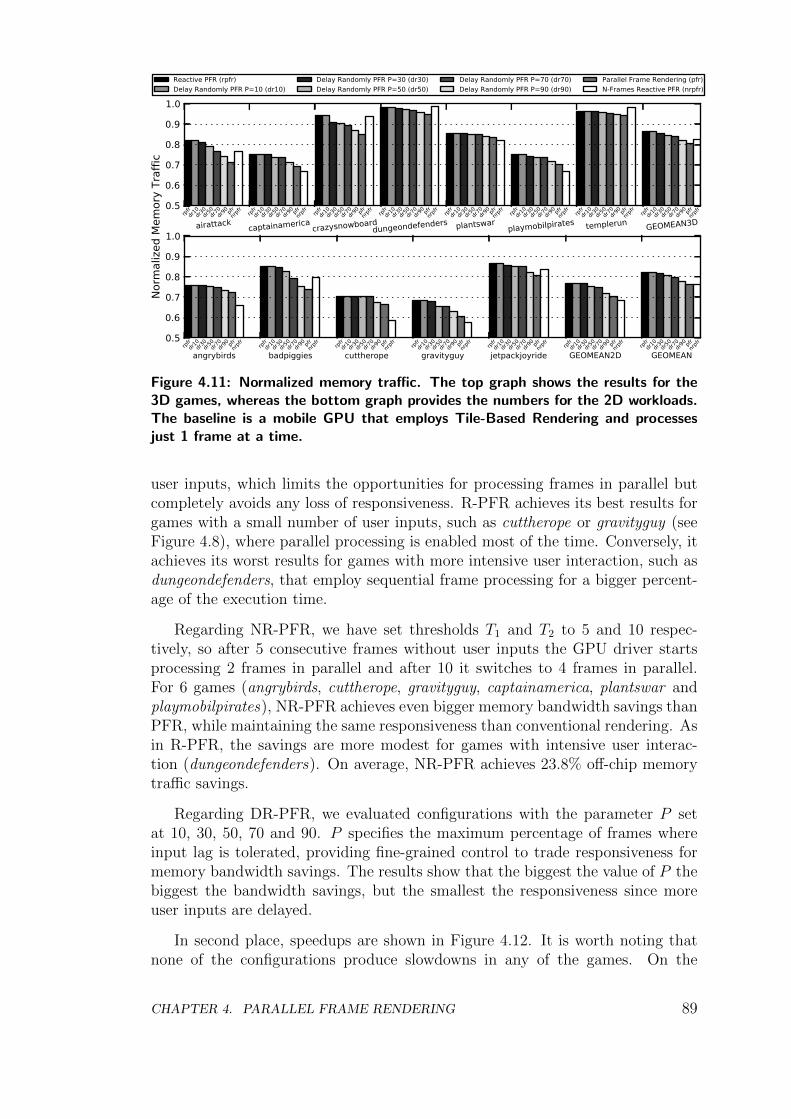
0.5
0.6
0.7
0.8
0.9
1.0
airattackrpf
rdr1
0dr3
0dr5
0dr7
0dr9
0 pfrnrpfr
captainamericarpf
rdr1
0dr3
0dr5
0dr7
0dr9
0 pfrnrpfr
crazysnowboardrpf
rdr1
0dr3
0dr5
0dr7
0dr9
0 pfrnrpfr
dungeondefendersrpf
rdr1
0dr3
0dr5
0dr7
0dr9
0 pfrnrpfr
plantswarrpf
rdr1
0dr3
0dr5
0dr7
0dr9
0 pfrnrpfr
playmobilpiratesrpf
rdr1
0dr3
0dr5
0dr7
0dr9
0 pfrnrpfr
templerunrpf
rdr1
0dr3
0dr5
0dr7
0dr9
0 pfrnrpfr
GEOMEAN3Drpf
rdr1
0dr3
0dr5
0dr7
0dr9
0 pfrnrpfr
Norm
aliz
ed M
emor
y Tr
affic
Reactive PFR (rpfr)Delay Randomly PFR P=10 (dr10)
Delay Randomly PFR P=30 (dr30)Delay Randomly PFR P=50 (dr50)
Delay Randomly PFR P=70 (dr70)Delay Randomly PFR P=90 (dr90)
Parallel Frame Rendering (pfr)N-Frames Reactive PFR (nrpfr)
0.5
0.6
0.7
0.8
0.9
1.0
angrybirdsrpf
rdr1
0dr3
0dr5
0dr7
0dr9
0 pfrnrpfr
badpiggiesrpf
rdr1
0dr3
0dr5
0dr7
0dr9
0 pfrnrpfr
cuttheroperpf
rdr1
0dr3
0dr5
0dr7
0dr9
0 pfrnrpfr
gravityguyrpf
rdr1
0dr3
0dr5
0dr7
0dr9
0 pfrnrpfr
jetpackjoyriderpf
rdr1
0dr3
0dr5
0dr7
0dr9
0 pfrnrpfr
GEOMEAN2Drpf
rdr1
0dr3
0dr5
0dr7
0dr9
0 pfrnrpfr
GEOMEANrpf
rdr1
0dr3
0dr5
0dr7
0dr9
0 pfrnrpfr
Figure 4.11: Normalized memory traffic. The top graph shows the results for the3D games, whereas the bottom graph provides the numbers for the 2D workloads.The baseline is a mobile GPU that employs Tile-Based Rendering and processesjust 1 frame at a time.
user inputs, which limits the opportunities for processing frames in parallel butcompletely avoids any loss of responsiveness. R-PFR achieves its best results forgames with a small number of user inputs, such as cuttherope or gravityguy (seeFigure 4.8), where parallel processing is enabled most of the time. Conversely, itachieves its worst results for games with more intensive user interaction, such asdungeondefenders, that employ sequential frame processing for a bigger percent-age of the execution time.
Regarding NR-PFR, we have set thresholds T1 and T2 to 5 and 10 respec-tively, so after 5 consecutive frames without user inputs the GPU driver startsprocessing 2 frames in parallel and after 10 it switches to 4 frames in parallel.For 6 games (angrybirds, cuttherope, gravityguy, captainamerica, plantswar andplaymobilpirates), NR-PFR achieves even bigger memory bandwidth savings thanPFR, while maintaining the same responsiveness than conventional rendering. Asin R-PFR, the savings are more modest for games with intensive user interac-tion (dungeondefenders). On average, NR-PFR achieves 23.8% off-chip memorytraffic savings.
Regarding DR-PFR, we evaluated configurations with the parameter P setat 10, 30, 50, 70 and 90. P specifies the maximum percentage of frames whereinput lag is tolerated, providing fine-grained control to trade responsiveness formemory bandwidth savings. The results show that the biggest the value of P thebiggest the bandwidth savings, but the smallest the responsiveness since moreuser inputs are delayed.
In second place, speedups are shown in Figure 4.12. It is worth noting thatnone of the configurations produce slowdowns in any of the games. On the
CHAPTER 4. PARALLEL FRAME RENDERING 89
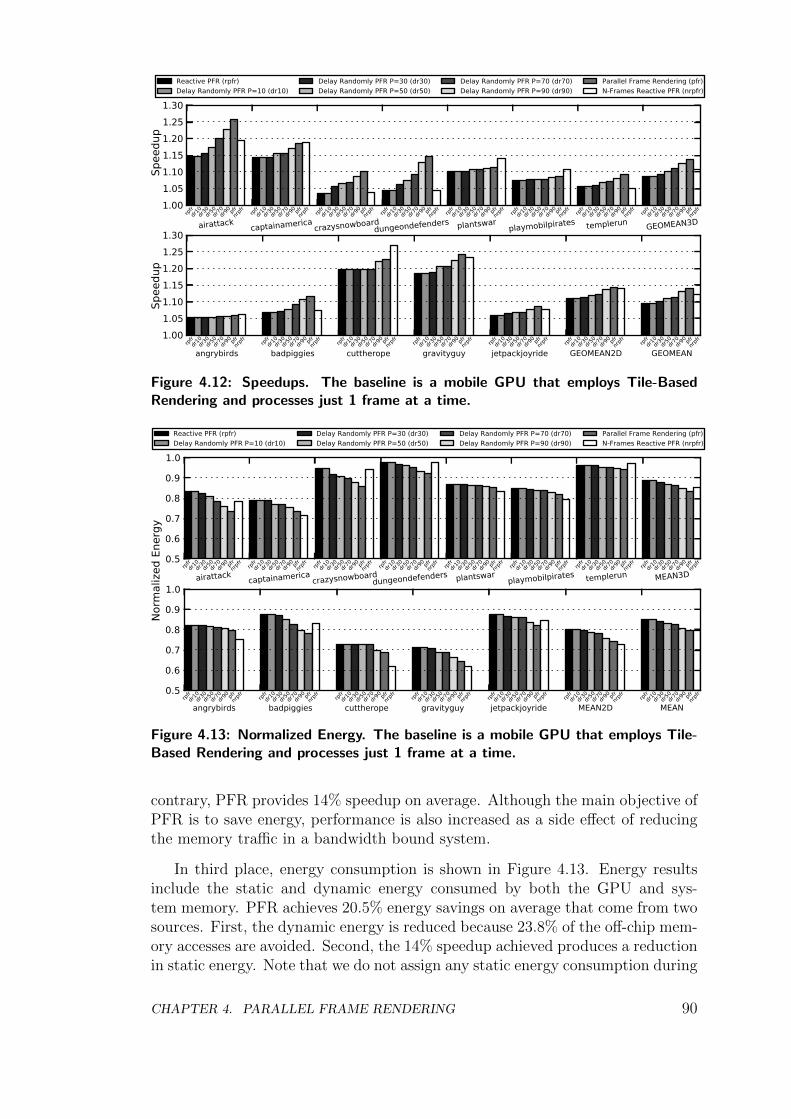
1.001.051.101.151.201.251.30
airattackrpf
rdr1
0dr3
0dr5
0dr7
0dr9
0 pfrnrpfr
captainamericarpf
rdr1
0dr3
0dr5
0dr7
0dr9
0 pfrnrpfr
crazysnowboardrpf
rdr1
0dr3
0dr5
0dr7
0dr9
0 pfrnrpfr
dungeondefendersrpf
rdr1
0dr3
0dr5
0dr7
0dr9
0 pfrnrpfr
plantswarrpf
rdr1
0dr3
0dr5
0dr7
0dr9
0 pfrnrpfr
playmobilpiratesrpf
rdr1
0dr3
0dr5
0dr7
0dr9
0 pfrnrpfr
templerunrpf
rdr1
0dr3
0dr5
0dr7
0dr9
0 pfrnrpfr
GEOMEAN3Drpf
rdr1
0dr3
0dr5
0dr7
0dr9
0 pfrnrpfr
Spee
dup
Spee
dup
Reactive PFR (rpfr)Delay Randomly PFR P=10 (dr10)
Delay Randomly PFR P=30 (dr30)Delay Randomly PFR P=50 (dr50)
Delay Randomly PFR P=70 (dr70)Delay Randomly PFR P=90 (dr90)
Parallel Frame Rendering (pfr)N-Frames Reactive PFR (nrpfr)
1.001.051.101.151.201.251.30
angrybirdsrpf
rdr1
0dr3
0dr5
0dr7
0dr9
0 pfrnrpfr
badpiggiesrpf
rdr1
0dr3
0dr5
0dr7
0dr9
0 pfrnrpfr
cuttheroperpf
rdr1
0dr3
0dr5
0dr7
0dr9
0 pfrnrpfr
gravityguyrpf
rdr1
0dr3
0dr5
0dr7
0dr9
0 pfrnrpfr
jetpackjoyriderpf
rdr1
0dr3
0dr5
0dr7
0dr9
0 pfrnrpfr
GEOMEAN2Drpf
rdr1
0dr3
0dr5
0dr7
0dr9
0 pfrnrpfr
GEOMEANrpf
rdr1
0dr3
0dr5
0dr7
0dr9
0 pfrnrpfr
Figure 4.12: Speedups. The baseline is a mobile GPU that employs Tile-BasedRendering and processes just 1 frame at a time.
0.5
0.6
0.7
0.8
0.9
1.0
airattackrpf
rdr1
0dr3
0dr5
0dr7
0dr9
0 pfrnrpfr
captainamericarpf
rdr1
0dr3
0dr5
0dr7
0dr9
0 pfrnrpfr
crazysnowboardrpf
rdr1
0dr3
0dr5
0dr7
0dr9
0 pfrnrpfr
dungeondefendersrpf
rdr1
0dr3
0dr5
0dr7
0dr9
0 pfrnrpfr
plantswarrpf
rdr1
0dr3
0dr5
0dr7
0dr9
0 pfrnrpfr
playmobilpiratesrpf
rdr1
0dr3
0dr5
0dr7
0dr9
0 pfrnrpfr
templerunrpf
rdr1
0dr3
0dr5
0dr7
0dr9
0 pfrnrpfr
MEAN3Drpf
rdr1
0dr3
0dr5
0dr7
0dr9
0 pfrnrpfr
Norm
aliz
ed E
nerg
y
Reactive PFR (rpfr)Delay Randomly PFR P=10 (dr10)
Delay Randomly PFR P=30 (dr30)Delay Randomly PFR P=50 (dr50)
Delay Randomly PFR P=70 (dr70)Delay Randomly PFR P=90 (dr90)
Parallel Frame Rendering (pfr)N-Frames Reactive PFR (nrpfr)
0.5
0.6
0.7
0.8
0.9
1.0
angrybirdsrpf
rdr1
0dr3
0dr5
0dr7
0dr9
0 pfrnrpfr
badpiggiesrpf
rdr1
0dr3
0dr5
0dr7
0dr9
0 pfrnrpfr
cuttheroperpf
rdr1
0dr3
0dr5
0dr7
0dr9
0 pfrnrpfr
gravityguyrpf
rdr1
0dr3
0dr5
0dr7
0dr9
0 pfrnrpfr
jetpackjoyriderpf
rdr1
0dr3
0dr5
0dr7
0dr9
0 pfrnrpfr
MEAN2Drpf
rdr1
0dr3
0dr5
0dr7
0dr9
0 pfrnrpfr
MEANrpf
rdr1
0dr3
0dr5
0dr7
0dr9
0 pfrnrpfr
Figure 4.13: Normalized Energy. The baseline is a mobile GPU that employs Tile-Based Rendering and processes just 1 frame at a time.
contrary, PFR provides 14% speedup on average. Although the main objective ofPFR is to save energy, performance is also increased as a side effect of reducingthe memory traffic in a bandwidth bound system.
In third place, energy consumption is shown in Figure 4.13. Energy resultsinclude the static and dynamic energy consumed by both the GPU and sys-tem memory. PFR achieves 20.5% energy savings on average that come from twosources. First, the dynamic energy is reduced because 23.8% of the off-chip mem-ory accesses are avoided. Second, the 14% speedup achieved produces a reductionin static energy. Note that we do not assign any static energy consumption during
CHAPTER 4. PARALLEL FRAME RENDERING 90
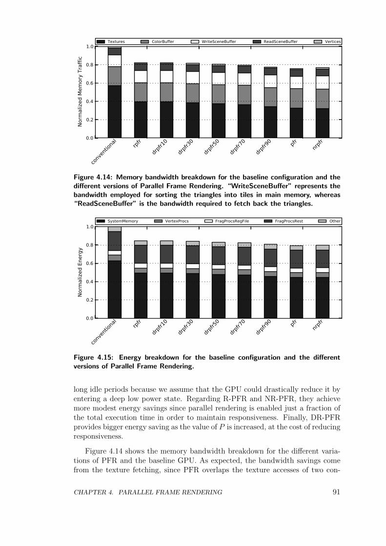
0.0
0.2
0.4
0.6
0.8
1.0
Norm
aliz
ed M
emor
y Tr
affic
conv
entio
nal
rpfr
drpfr1
0
drpfr3
0
drpfr5
0
drpfr7
0
drpfr9
0 pfr nrpfr
Textures ColorBuffer WriteSceneBuffer ReadSceneBuffer Vertices
Figure 4.14: Memory bandwidth breakdown for the baseline configuration and thedifferent versions of Parallel Frame Rendering. “WriteSceneBuffer” represents thebandwidth employed for sorting the triangles into tiles in main memory, whereas“ReadSceneBuffer” is the bandwidth required to fetch back the triangles.
0.0
0.2
0.4
0.6
0.8
1.0
Norm
aliz
ed E
nerg
y
conv
entio
nal
rpfr
drpfr1
0
drpfr3
0
drpfr5
0
drpfr7
0
drpfr9
0 pfr nrpfr
SystemMemory VertexProcs FragProcsRegFile FragProcsRest Other
Figure 4.15: Energy breakdown for the baseline configuration and the differentversions of Parallel Frame Rendering.
long idle periods because we assume that the GPU could drastically reduce it byentering a deep low power state. Regarding R-PFR and NR-PFR, they achievemore modest energy savings since parallel rendering is enabled just a fraction ofthe total execution time in order to maintain responsiveness. Finally, DR-PFRprovides bigger energy saving as the value of P is increased, at the cost of reducingresponsiveness.
Figure 4.14 shows the memory bandwidth breakdown for the different varia-tions of PFR and the baseline GPU. As expected, the bandwidth savings comefrom the texture fetching, since PFR overlaps the texture accesses of two con-
CHAPTER 4. PARALLEL FRAME RENDERING 91
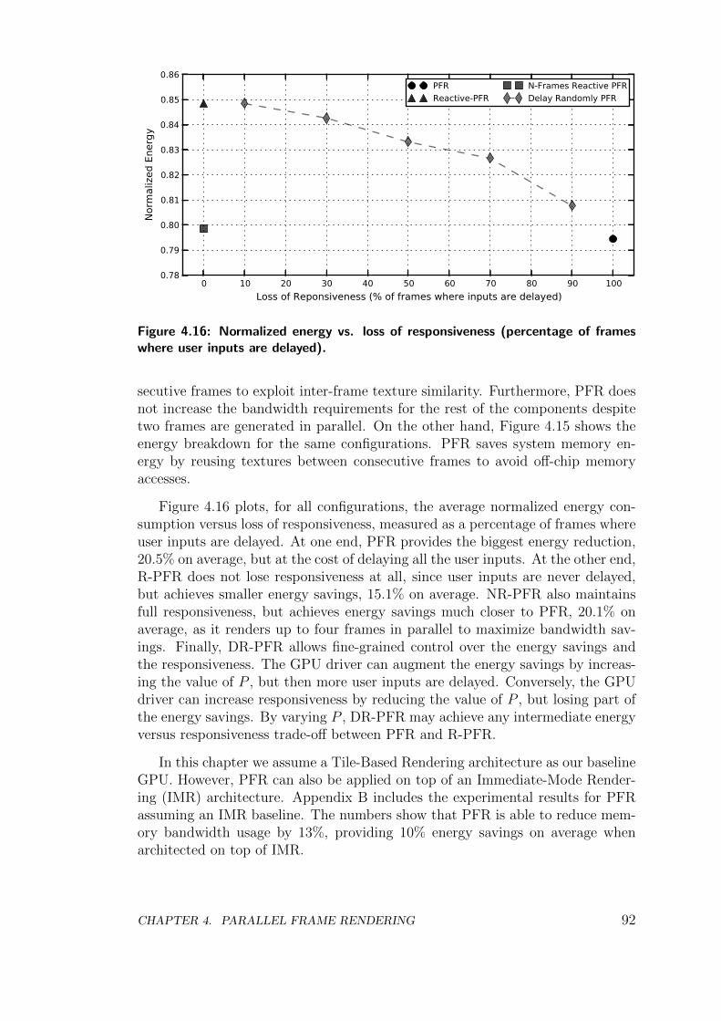
0 10 20 30 40 50 60 70 80 90 100Loss of Reponsiveness (% of frames where inputs are delayed)
0.78
0.79
0.80
0.81
0.82
0.83
0.84
0.85
0.86
Norm
aliz
ed E
nerg
y
PFRReactive-PFR
N-Frames Reactive PFRDelay Randomly PFR
Figure 4.16: Normalized energy vs. loss of responsiveness (percentage of frameswhere user inputs are delayed).
secutive frames to exploit inter-frame texture similarity. Furthermore, PFR doesnot increase the bandwidth requirements for the rest of the components despitetwo frames are generated in parallel. On the other hand, Figure 4.15 shows theenergy breakdown for the same configurations. PFR saves system memory en-ergy by reusing textures between consecutive frames to avoid off-chip memoryaccesses.
Figure 4.16 plots, for all configurations, the average normalized energy con-sumption versus loss of responsiveness, measured as a percentage of frames whereuser inputs are delayed. At one end, PFR provides the biggest energy reduction,20.5% on average, but at the cost of delaying all the user inputs. At the other end,R-PFR does not lose responsiveness at all, since user inputs are never delayed,but achieves smaller energy savings, 15.1% on average. NR-PFR also maintainsfull responsiveness, but achieves energy savings much closer to PFR, 20.1% onaverage, as it renders up to four frames in parallel to maximize bandwidth sav-ings. Finally, DR-PFR allows fine-grained control over the energy savings andthe responsiveness. The GPU driver can augment the energy savings by increas-ing the value of P , but then more user inputs are delayed. Conversely, the GPUdriver can increase responsiveness by reducing the value of P , but losing part ofthe energy savings. By varying P , DR-PFR may achieve any intermediate energyversus responsiveness trade-off between PFR and R-PFR.
In this chapter we assume a Tile-Based Rendering architecture as our baselineGPU. However, PFR can also be applied on top of an Immediate-Mode Render-ing (IMR) architecture. Appendix B includes the experimental results for PFRassuming an IMR baseline. The numbers show that PFR is able to reduce mem-ory bandwidth usage by 13%, providing 10% energy savings on average whenarchitected on top of IMR.
CHAPTER 4. PARALLEL FRAME RENDERING 92
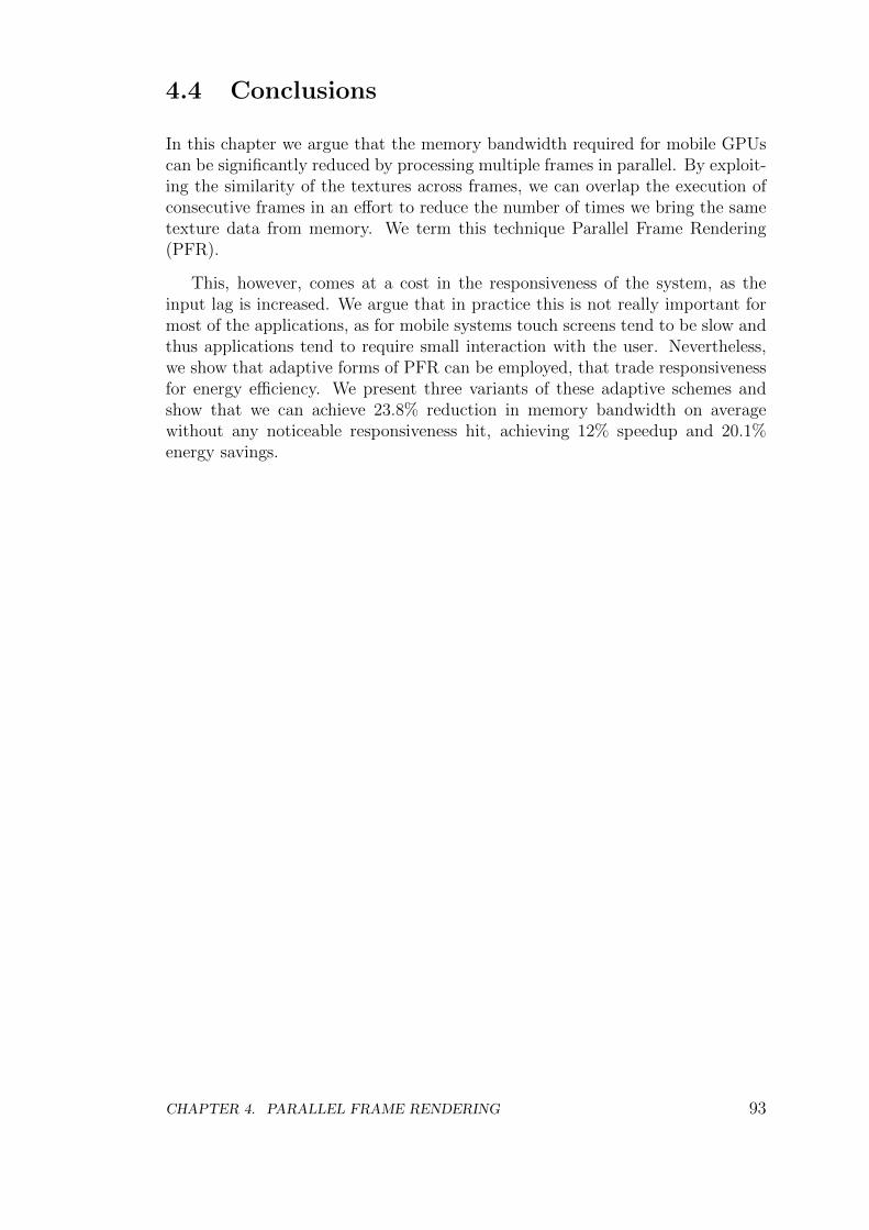
4.4 Conclusions
In this chapter we argue that the memory bandwidth required for mobile GPUscan be significantly reduced by processing multiple frames in parallel. By exploit-ing the similarity of the textures across frames, we can overlap the execution ofconsecutive frames in an effort to reduce the number of times we bring the sametexture data from memory. We term this technique Parallel Frame Rendering(PFR).
This, however, comes at a cost in the responsiveness of the system, as theinput lag is increased. We argue that in practice this is not really important formost of the applications, as for mobile systems touch screens tend to be slow andthus applications tend to require small interaction with the user. Nevertheless,we show that adaptive forms of PFR can be employed, that trade responsivenessfor energy efficiency. We present three variants of these adaptive schemes andshow that we can achieve 23.8% reduction in memory bandwidth on averagewithout any noticeable responsiveness hit, achieving 12% speedup and 20.1%energy savings.
CHAPTER 4. PARALLEL FRAME RENDERING 93

CHAPTER 4. PARALLEL FRAME RENDERING 94
Chapter 5
Hardware Memoization in MobileGPUs
In this chapter we address the problem of removing redundant executions of theFragment Program. In first place we argue that graphical applications exhibit ahigh degree of redundancy, since generating an animation typically involves thesuccession of extremely similar images. In terms of rendering these images, thisbehavior translates into the creation of many fragment programs with the exactsame input data. We measure this fragment redundancy for a set of commercialAndroid applications and show that, on average, more than 38% of the fragmentsused in a frame have been already computed in a prior frame.
In second place, we try to exploit this redundancy using fragment memoiza-tion. Unfortunately, this is not an easy task as most of the redundancy existsacross frames, rendering most hardware based schemes unfeasible. We thus firsttake a step back and try to analyze the temporal locality of the redundant frag-ments, their complexity, and the number of inputs typically seen in fragmentprograms. The result of our analysis is a task level memoization scheme, thatoutperforms the current state-of-the-art in low power GPUs.
Finally, we evaluate our memoization scheme by using several Android com-mercial games, and show that our system is able to remove 42.2% of the redundantfragment computations on average. This materializes to a significant speedup of15% on average, while also improving the overall energy consumption by 12%.
5.1 Redundancy in Mobile GPUs
Graphical applications for mobile devices tend to exhibit a large degree of scenereplication across frames. Figure 5.1 shows two consecutive frames of a popularAndroid game, Bad Piggies. As it can be seen, the input from the user resultedin the main character being shifted, however a significant fraction of the frameremained untouched. Despite being admittedly a well selected example, this
CHAPTER 5. HARDWARE MEMOIZATION IN MOBILE GPUS 95
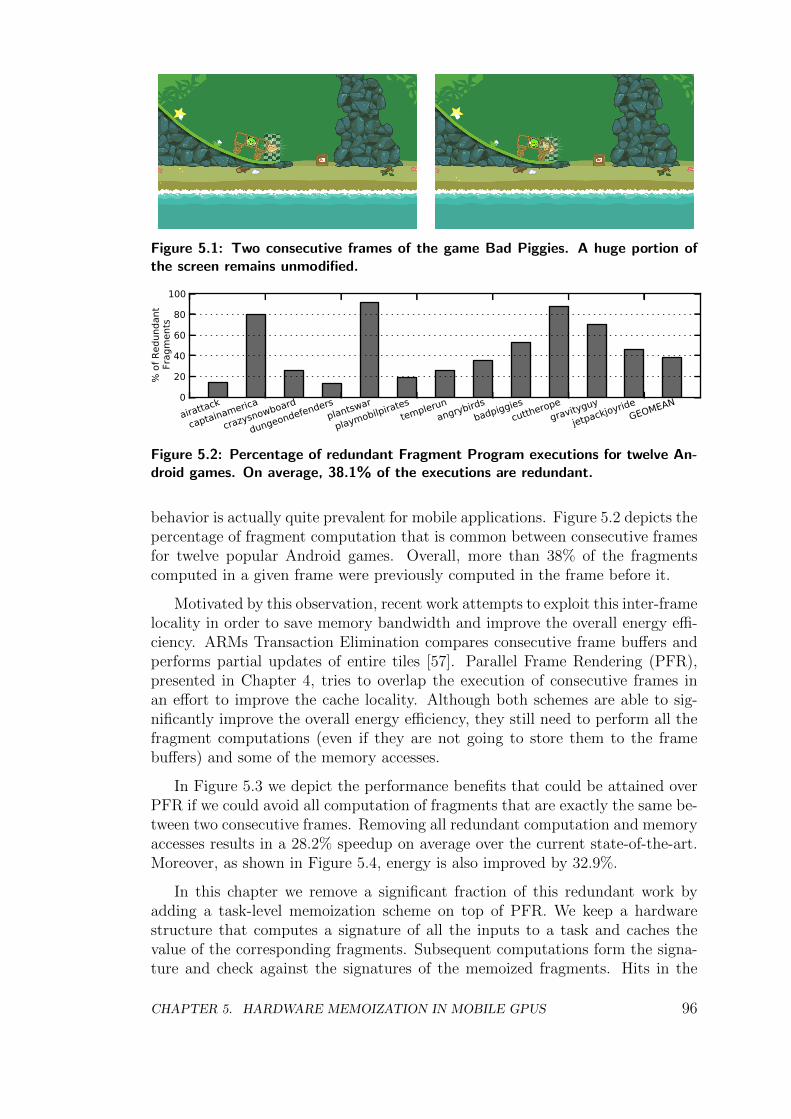
Figure 5.1: Two consecutive frames of the game Bad Piggies. A huge portion ofthe screen remains unmodified.
0
20
40
60
80
100
% o
f Red
unda
ntFr
agm
ents
airattack
captainamerica
crazysnowboard
dungeondefendersplantswar
playmobilpiratestemplerun
angrybirdsbadpiggies
cuttheropegravityguy
jetpackjoyrideGEOMEAN
Figure 5.2: Percentage of redundant Fragment Program executions for twelve An-droid games. On average, 38.1% of the executions are redundant.
behavior is actually quite prevalent for mobile applications. Figure 5.2 depicts thepercentage of fragment computation that is common between consecutive framesfor twelve popular Android games. Overall, more than 38% of the fragmentscomputed in a given frame were previously computed in the frame before it.
Motivated by this observation, recent work attempts to exploit this inter-framelocality in order to save memory bandwidth and improve the overall energy effi-ciency. ARMs Transaction Elimination compares consecutive frame buffers andperforms partial updates of entire tiles [57]. Parallel Frame Rendering (PFR),presented in Chapter 4, tries to overlap the execution of consecutive frames inan effort to improve the cache locality. Although both schemes are able to sig-nificantly improve the overall energy efficiency, they still need to perform all thefragment computations (even if they are not going to store them to the framebuffers) and some of the memory accesses.
In Figure 5.3 we depict the performance benefits that could be attained overPFR if we could avoid all computation of fragments that are exactly the same be-tween two consecutive frames. Removing all redundant computation and memoryaccesses results in a 28.2% speedup on average over the current state-of-the-art.Moreover, as shown in Figure 5.4, energy is also improved by 32.9%.
In this chapter we remove a significant fraction of this redundant work byadding a task-level memoization scheme on top of PFR. We keep a hardwarestructure that computes a signature of all the inputs to a task and caches thevalue of the corresponding fragments. Subsequent computations form the signa-ture and check against the signatures of the memoized fragments. Hits in the
CHAPTER 5. HARDWARE MEMOIZATION IN MOBILE GPUS 96
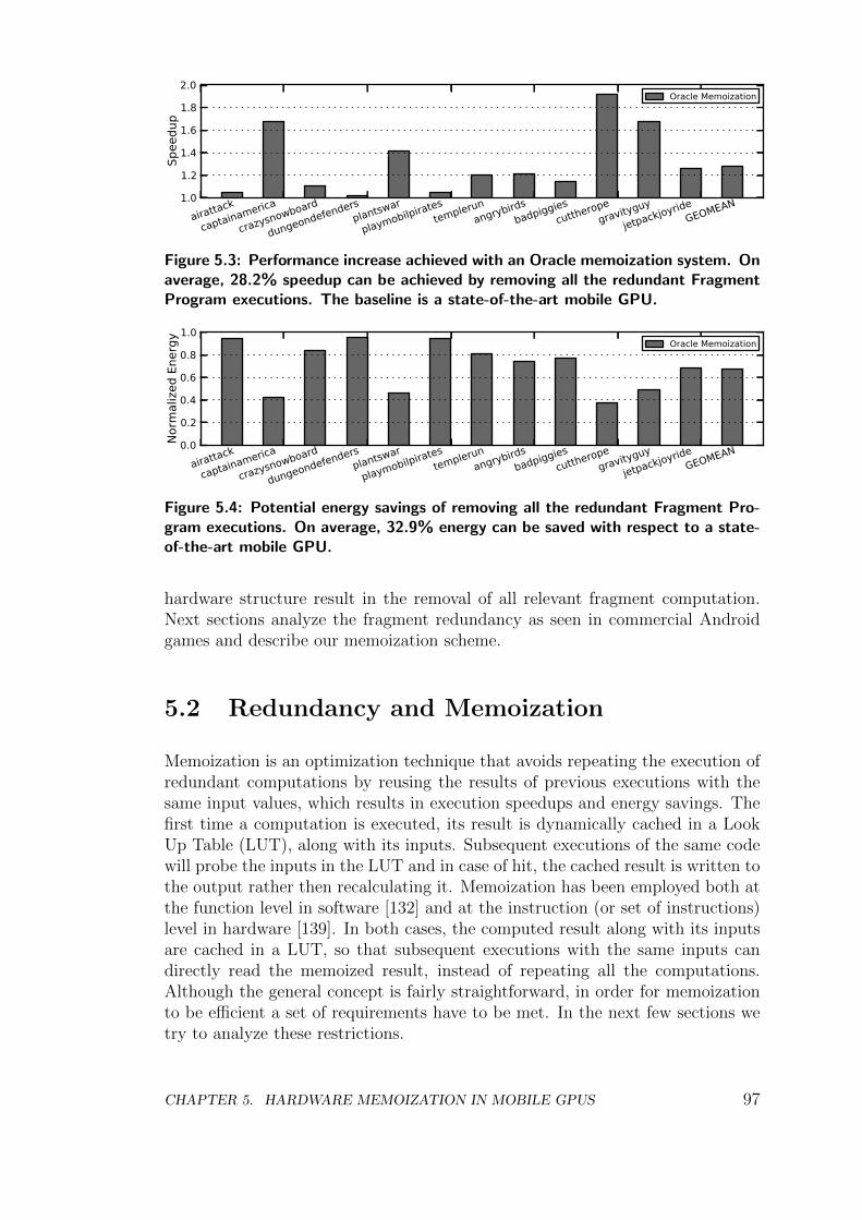
1.0
1.2
1.4
1.6
1.8
2.0
Spee
dup
airattack
captainamerica
crazysnowboard
dungeondefendersplantswar
playmobilpiratestemplerun
angrybirdsbadpiggies
cuttheropegravityguy
jetpackjoyrideGEOMEAN
Oracle Memoization
Figure 5.3: Performance increase achieved with an Oracle memoization system. Onaverage, 28.2% speedup can be achieved by removing all the redundant FragmentProgram executions. The baseline is a state-of-the-art mobile GPU.
0.0
0.2
0.4
0.6
0.8
1.0
Norm
aliz
ed E
nerg
y
airattack
captainamerica
crazysnowboard
dungeondefendersplantswar
playmobilpiratestemplerun
angrybirdsbadpiggies
cuttheropegravityguy
jetpackjoyrideGEOMEAN
Oracle Memoization
Figure 5.4: Potential energy savings of removing all the redundant Fragment Pro-gram executions. On average, 32.9% energy can be saved with respect to a state-of-the-art mobile GPU.
hardware structure result in the removal of all relevant fragment computation.Next sections analyze the fragment redundancy as seen in commercial Androidgames and describe our memoization scheme.
5.2 Redundancy and Memoization
Memoization is an optimization technique that avoids repeating the execution ofredundant computations by reusing the results of previous executions with thesame input values, which results in execution speedups and energy savings. Thefirst time a computation is executed, its result is dynamically cached in a LookUp Table (LUT), along with its inputs. Subsequent executions of the same codewill probe the inputs in the LUT and in case of hit, the cached result is written tothe output rather then recalculating it. Memoization has been employed both atthe function level in software [132] and at the instruction (or set of instructions)level in hardware [139]. In both cases, the computed result along with its inputsare cached in a LUT, so that subsequent executions with the same inputs candirectly read the memoized result, instead of repeating all the computations.Although the general concept is fairly straightforward, in order for memoizationto be efficient a set of requirements have to be met. In the next few sections wetry to analyze these restrictions.
CHAPTER 5. HARDWARE MEMOIZATION IN MOBILE GPUS 97
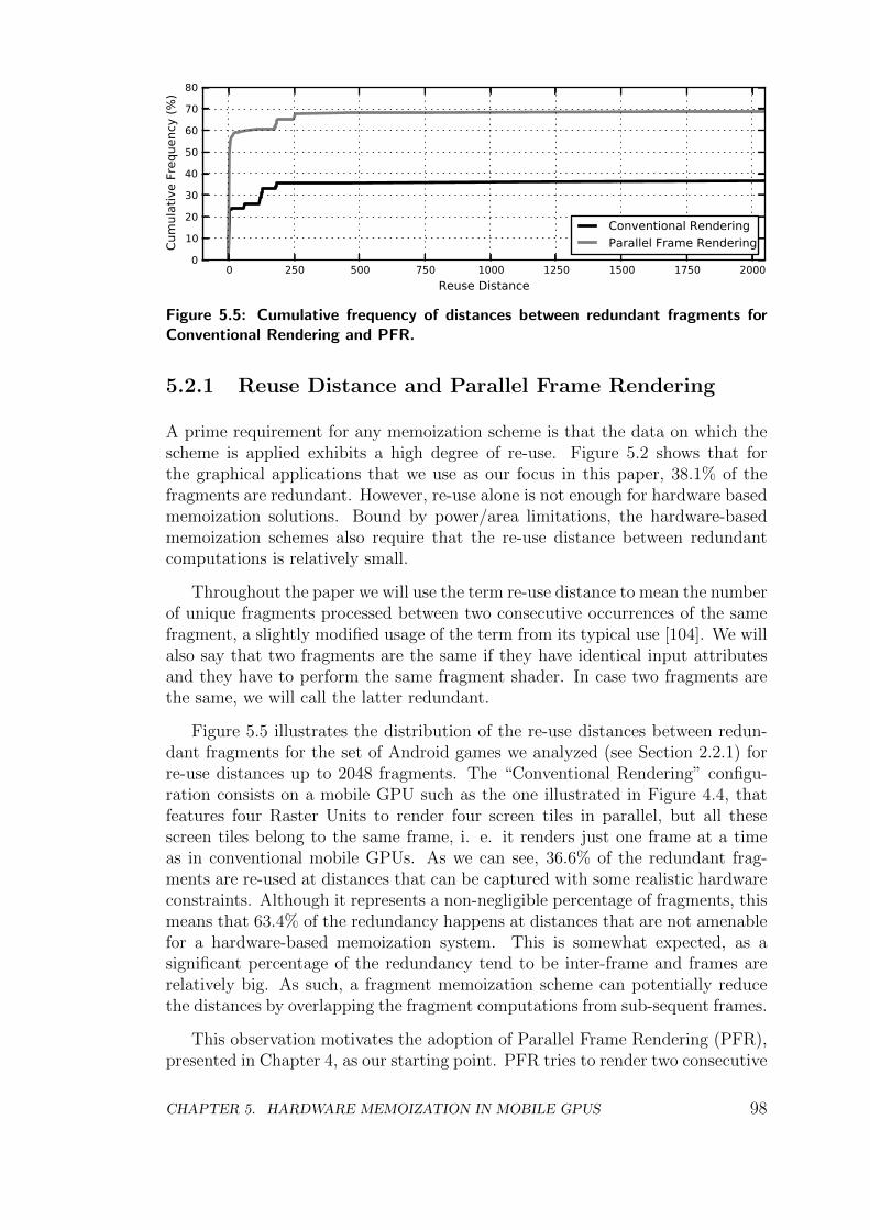
0 250 500 750 1000 1250 1500 1750 2000Reuse Distance
0
10
20
30
40
50
60
70
80
Cum
ulat
ive
Freq
uenc
y (%
)
Conventional RenderingParallel Frame Rendering
Figure 5.5: Cumulative frequency of distances between redundant fragments forConventional Rendering and PFR.
5.2.1 Reuse Distance and Parallel Frame Rendering
A prime requirement for any memoization scheme is that the data on which thescheme is applied exhibits a high degree of re-use. Figure 5.2 shows that forthe graphical applications that we use as our focus in this paper, 38.1% of thefragments are redundant. However, re-use alone is not enough for hardware basedmemoization solutions. Bound by power/area limitations, the hardware-basedmemoization schemes also require that the re-use distance between redundantcomputations is relatively small.
Throughout the paper we will use the term re-use distance to mean the numberof unique fragments processed between two consecutive occurrences of the samefragment, a slightly modified usage of the term from its typical use [104]. We willalso say that two fragments are the same if they have identical input attributesand they have to perform the same fragment shader. In case two fragments arethe same, we will call the latter redundant.
Figure 5.5 illustrates the distribution of the re-use distances between redun-dant fragments for the set of Android games we analyzed (see Section 2.2.1) forre-use distances up to 2048 fragments. The “Conventional Rendering” configu-ration consists on a mobile GPU such as the one illustrated in Figure 4.4, thatfeatures four Raster Units to render four screen tiles in parallel, but all thesescreen tiles belong to the same frame, i. e. it renders just one frame at a timeas in conventional mobile GPUs. As we can see, 36.6% of the redundant frag-ments are re-used at distances that can be captured with some realistic hardwareconstraints. Although it represents a non-negligible percentage of fragments, thismeans that 63.4% of the redundancy happens at distances that are not amenablefor a hardware-based memoization system. This is somewhat expected, as asignificant percentage of the redundancy tend to be inter-frame and frames arerelatively big. As such, a fragment memoization scheme can potentially reducethe distances by overlapping the fragment computations from sub-sequent frames.
This observation motivates the adoption of Parallel Frame Rendering (PFR),presented in Chapter 4, as our starting point. PFR tries to render two consecutive
CHAPTER 5. HARDWARE MEMOIZATION IN MOBILE GPUS 98
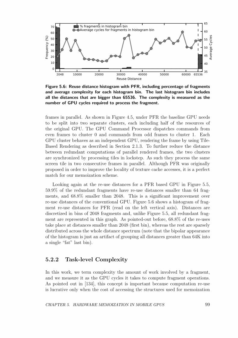
2048 10000 20000 30000 40000 50000 60000 65536Reuse Distance
0
10
20
30
40
50
60
70
Freq
uenc
y (%
)
% fragments in histogram binAverage cycles for fragments in histogram bin
35
40
45
50
55
60
65
Aver
age
Cycl
es
Figure 5.6: Reuse distance histogram with PFR, including percentage of fragmentsand average complexity for each histogram bin. The last histogram bin includesall the distances that are bigger than 65536. The complexity is measured as thenumber of GPU cycles required to process the fragment.
frames in parallel. As shown in Figure 4.5, under PFR the baseline GPU needsto be split into two separate clusters, each including half of the resources ofthe original GPU. The GPU Command Processor dispatches commands fromeven frames to cluster 0 and commands from odd frames to cluster 1. EachGPU cluster behaves as an independent GPU, rendering the frame by using Tile-Based Rendering as described in Section 2.1.3. To further reduce the distancebetween redundant computations of parallel rendered frames, the two clustersare synchronized by processing tiles in lockstep. As such they process the samescreen tile in two consecutive frames in parallel. Although PFR was originallyproposed in order to improve the locality of texture cache accesses, it is a perfectmatch for our memoization scheme.
Looking again at the re-use distances for a PFR based GPU in Figure 5.5,59.9% of the redundant fragments have re-use distances smaller than 64 frag-ments, and 68.8% smaller than 2048. This is a significant improvement overre-use distances of the conventional GPU. Figure 5.6 shows a histogram of frag-ment re-use distances for PFR (read on the left vertical axis). Distances arediscretized in bins of 2048 fragments and, unlike Figure 5.5, all redundant frag-ment are represented in this graph. As pointed-out before, 68.8% of the re-usestake place at distances smaller than 2048 (first bin), whereas the rest are sparselydistributed across the whole distance spectrum (note that the bipolar appearanceof the histogram is just an artifact of grouping all distances greater than 64K intoa single “fat” last bin).
5.2.2 Task-level Complexity
In this work, we term complexity the amount of work involved by a fragment,and we measure it as the GPU cycles it takes to compute fragment operations.As pointed out in [134], this concept is important because computation re-useis lucrative only when the cost of accessing the structures used for memoization
CHAPTER 5. HARDWARE MEMOIZATION IN MOBILE GPUS 99
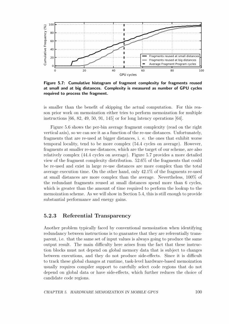
0 20 40 60 80 100GPU cycles
0
20
40
60
80
100
Cum
ulat
ive
Freq
uenc
y (%
)
Fragments reused at small distancesFragments reused at big distancesAverage Fragment Program cycles
Figure 5.7: Cumulative histogram of fragment complexity for fragments reusedat small and at big distances. Complexity is measured as number of GPU cyclesrequired to process the fragment.
is smaller than the benefit of skipping the actual computation. For this rea-son prior work on memoization either tries to perform memoization for multipleinstructions [66, 82, 49, 50, 91, 145] or for long latency operations [64].
Figure 5.6 shows the per-bin average fragment complexity (read on the rightvertical axis), so we can see it as a function of the re-use distances. Unfortunately,fragments that are re-used at bigger distances, i. e. the ones that exhibit worsetemporal locality, tend to be more complex (54.4 cycles on average). However,fragments at smaller re-use distances, which are the target of our scheme, are alsorelatively complex (44.4 cycles on average). Figure 5.7 provides a more detailedview of the fragment complexity distribution. 52.6% of the fragments that couldbe re-used and exist in large re-use distances are more complex than the totalaverage execution time. On the other hand, only 42.1% of the fragments re-usedat small distances are more complex than the average. Nevertheless, 100% ofthe redundant fragments reused at small distances spend more than 6 cycles,which is greater than the amount of time required to perform the lookup to thememoization scheme. As we will show in Section 5.4, this is still enough to providesubstantial performance and energy gains.
5.2.3 Referential Transparency
Another problem typically faced by conventional memoization when identifyingredundancy between instructions is to guarantee that they are referentially trans-parent, i.e. that the same set of input values is always going to produce the sameoutput result. The main difficulty here arises from the fact that these instruc-tion blocks must not depend on global memory data that is subject to changesbetween executions, and they do not produce side-effects. Since it is difficultto track these global changes at runtime, task-level hardware-based memoizationusually requires compiler support to carefully select code regions that do notdepend on global data or have side-effects, which further reduces the choice ofcandidate code regions.
CHAPTER 5. HARDWARE MEMOIZATION IN MOBILE GPUS 100
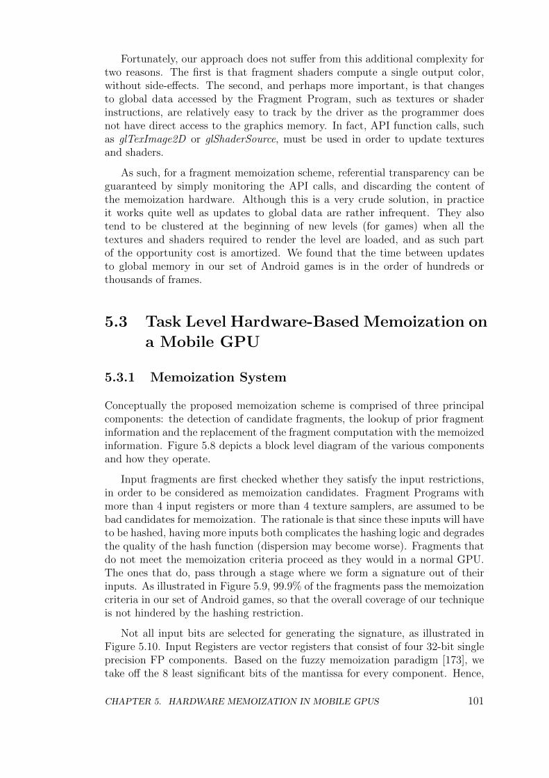
Fortunately, our approach does not suffer from this additional complexity fortwo reasons. The first is that fragment shaders compute a single output color,without side-effects. The second, and perhaps more important, is that changesto global data accessed by the Fragment Program, such as textures or shaderinstructions, are relatively easy to track by the driver as the programmer doesnot have direct access to the graphics memory. In fact, API function calls, suchas glTexImage2D or glShaderSource, must be used in order to update texturesand shaders.
As such, for a fragment memoization scheme, referential transparency can beguaranteed by simply monitoring the API calls, and discarding the content ofthe memoization hardware. Although this is a very crude solution, in practiceit works quite well as updates to global data are rather infrequent. They alsotend to be clustered at the beginning of new levels (for games) when all thetextures and shaders required to render the level are loaded, and as such partof the opportunity cost is amortized. We found that the time between updatesto global memory in our set of Android games is in the order of hundreds orthousands of frames.
5.3 Task Level Hardware-Based Memoization on
a Mobile GPU
5.3.1 Memoization System
Conceptually the proposed memoization scheme is comprised of three principalcomponents: the detection of candidate fragments, the lookup of prior fragmentinformation and the replacement of the fragment computation with the memoizedinformation. Figure 5.8 depicts a block level diagram of the various componentsand how they operate.
Input fragments are first checked whether they satisfy the input restrictions,in order to be considered as memoization candidates. Fragment Programs withmore than 4 input registers or more than 4 texture samplers, are assumed to bebad candidates for memoization. The rationale is that since these inputs will haveto be hashed, having more inputs both complicates the hashing logic and degradesthe quality of the hash function (dispersion may become worse). Fragments thatdo not meet the memoization criteria proceed as they would in a normal GPU.The ones that do, pass through a stage where we form a signature out of theirinputs. As illustrated in Figure 5.9, 99.9% of the fragments pass the memoizationcriteria in our set of Android games, so that the overall coverage of our techniqueis not hindered by the hashing restriction.
Not all input bits are selected for generating the signature, as illustrated inFigure 5.10. Input Registers are vector registers that consist of four 32-bit singleprecision FP components. Based on the fuzzy memoization paradigm [173], wetake off the 8 least significant bits of the mantissa for every component. Hence,
CHAPTER 5. HARDWARE MEMOIZATION IN MOBILE GPUS 101
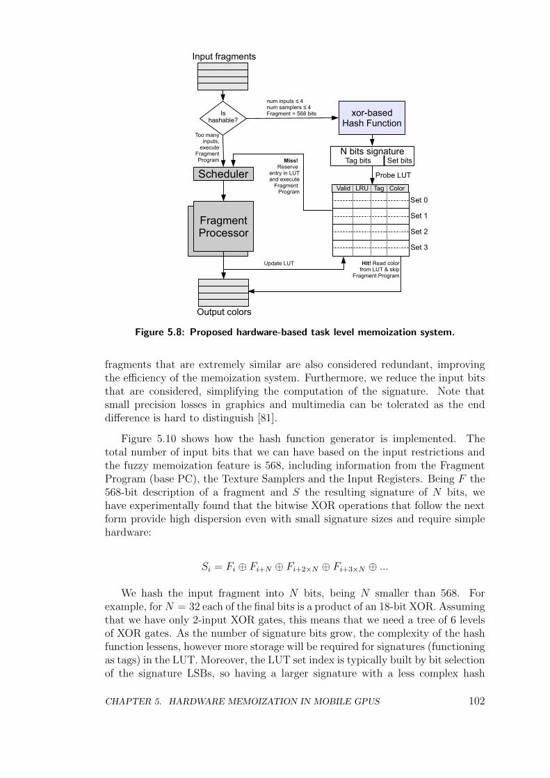
FragmentProcessor
Input fragments
Ishashable?
xor-basedHash Function
num inputs ≤ 4num samplers ≤ 4Fragment = 568 bits
FragmentProcessor
Too manyinputs,
executeFragmentProgram
N bits signature
Valid LRU Tag Color
Probe LUT
Miss! Reserve
entry in LUT and execute
Fragment Program
Output colors
Set 0
Set 1
Set 2
Set 3
Update LUT Hit! Read color from LUT & skip
Fragment Program
SchedulerSet bitsTag bits
Figure 5.8: Proposed hardware-based task level memoization system.
fragments that are extremely similar are also considered redundant, improvingthe efficiency of the memoization system. Furthermore, we reduce the input bitsthat are considered, simplifying the computation of the signature. Note thatsmall precision losses in graphics and multimedia can be tolerated as the enddifference is hard to distinguish [81].
Figure 5.10 shows how the hash function generator is implemented. Thetotal number of input bits that we can have based on the input restrictions andthe fuzzy memoization feature is 568, including information from the FragmentProgram (base PC), the Texture Samplers and the Input Registers. Being F the568-bit description of a fragment and S the resulting signature of N bits, wehave experimentally found that the bitwise XOR operations that follow the nextform provide high dispersion even with small signature sizes and require simplehardware:
Si = Fi ⊕ Fi+N ⊕ Fi+2×N ⊕ Fi+3×N ⊕ ...
We hash the input fragment into N bits, being N smaller than 568. Forexample, for N = 32 each of the final bits is a product of an 18-bit XOR. Assumingthat we have only 2-input XOR gates, this means that we need a tree of 6 levelsof XOR gates. As the number of signature bits grow, the complexity of the hashfunction lessens, however more storage will be required for signatures (functioningas tags) in the LUT. Moreover, the LUT set index is typically built by bit selectionof the signature LSBs, so having a larger signature with a less complex hash
CHAPTER 5. HARDWARE MEMOIZATION IN MOBILE GPUS 102
0 1 2 3 4 5 6Number of Inputs
0
20
40
60
80
100
Cum
ulat
ive
Perc
enta
geof
Fra
gmen
ts
Input RegistersTexture Samplers
Figure 5.9: Two cumulative histograms for the number of input registers and num-ber of texture samplers. With just 4 of each we cover 99.9% of the fragments,although in OpenGL ES the programmer can use up to 16 input registers and 8texture samplers.
function makes each index bit to be generated from a smaller number of fragmentbits. As we will show in Section 5.4, this puts more pressure to specific sets of theLUT, as the dispersion is much worse. This results in requirements of a biggerLUT, which is obviously not a good trade-off.
Since we perform a hash of many bits into few, we inevitably lose some in-formation. This results in what we call a false hit, which ultimately results in adistortion of the frame with respect to the one that would have been computedby a normal GPU. More bits in the hash result in a smaller probability for suchcollisions, but as we will see in Section 5.4, in practice there is little difference forsignatures bigger than 32 bits.
Once the hashing of the inputs is ready, we then perform a lookup to theLook Up Table (LUT). The LUT acts as a cache, in that it uses part of thesignature as an index, and the rest as the tag. The LUT is set-associative, andwe employ pseudo LRU [48] as its replacement policy. Each entry of the LUTcontains control information and data. Regarding the control information, eachentry has a Valid bit, an LRU bit for the replacement policy and N − M bitsto store the most significant part of the signature that serves as the tag for theentry, being M the number of bits employed to select the set. Regarding thedata, each entry stores the 32-bit color, in RGBA format, that corresponds tothe given fragment.
A hit in the LUT indicates that we have a memoized value of the prior color ofthe fragment, and as such we can skip the fragment computation. Fragments thathit in the LUT read out the color and take the bypass to the next GPU stage.On the contrary, a miss in the LUT indicates that the output of the fragment isnot available. Missing fragments are redirected to the Fragment Processors wherethe Fragment Program is applied to compute the color. An entry in the given setis reserved for the fragment and the tags are updated, replacing a previous entryby using pseudo-LRU if there is no free entry available, and the fragment carriesthe index of the corresponding line.
CHAPTER 5. HARDWARE MEMOIZATION IN MOBILE GPUS 103
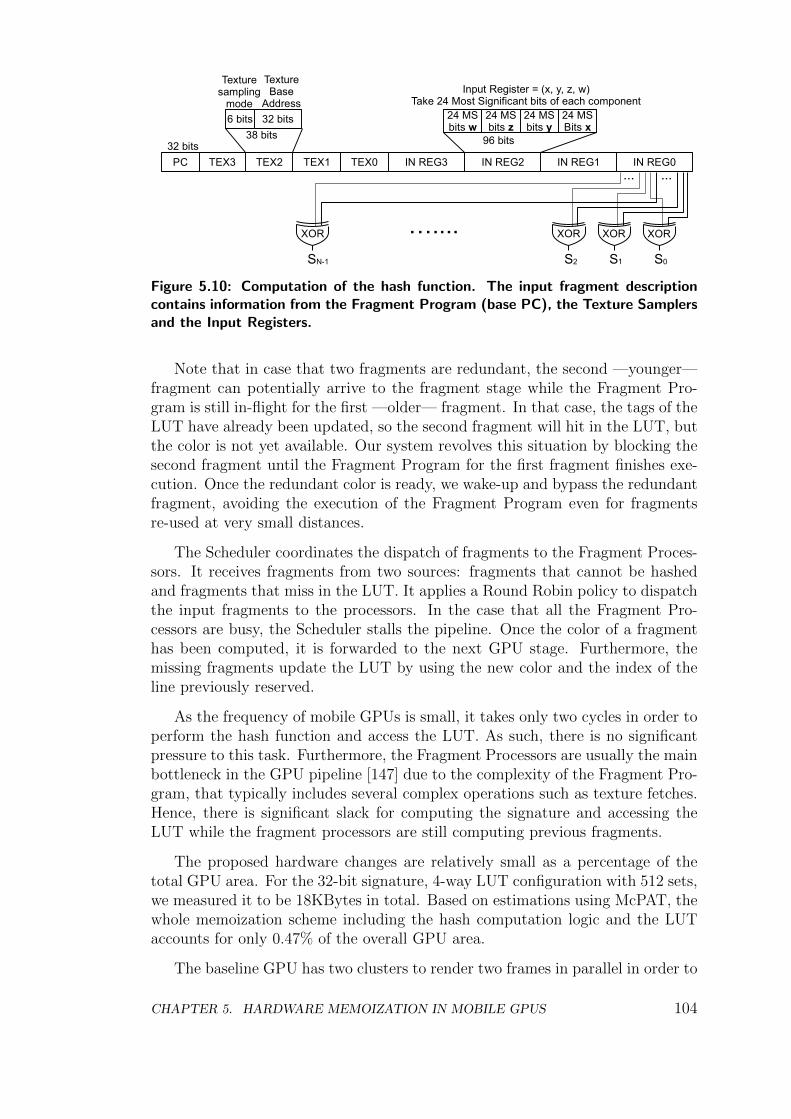
TEX3PC TEX2 TEX1 TEX0 IN REG3 IN REG2 IN REG1
32 bits
6 bits 32 bits
Texturesampling
mode
TextureBase
Address24 MSbits w
24 MSbits z
24 MSbits y
24 MSBits x
Input Register = (x, y, z, w)Take 24 Most Significant bits of each component
38 bits 96 bits
XOR
IN REG0
XORXORXOR …....S0S1S2SN-1
......
Figure 5.10: Computation of the hash function. The input fragment descriptioncontains information from the Fragment Program (base PC), the Texture Samplersand the Input Registers.
Note that in case that two fragments are redundant, the second —younger—fragment can potentially arrive to the fragment stage while the Fragment Pro-gram is still in-flight for the first —older— fragment. In that case, the tags of theLUT have already been updated, so the second fragment will hit in the LUT, butthe color is not yet available. Our system revolves this situation by blocking thesecond fragment until the Fragment Program for the first fragment finishes exe-cution. Once the redundant color is ready, we wake-up and bypass the redundantfragment, avoiding the execution of the Fragment Program even for fragmentsre-used at very small distances.
The Scheduler coordinates the dispatch of fragments to the Fragment Proces-sors. It receives fragments from two sources: fragments that cannot be hashedand fragments that miss in the LUT. It applies a Round Robin policy to dispatchthe input fragments to the processors. In the case that all the Fragment Pro-cessors are busy, the Scheduler stalls the pipeline. Once the color of a fragmenthas been computed, it is forwarded to the next GPU stage. Furthermore, themissing fragments update the LUT by using the new color and the index of theline previously reserved.
As the frequency of mobile GPUs is small, it takes only two cycles in order toperform the hash function and access the LUT. As such, there is no significantpressure to this task. Furthermore, the Fragment Processors are usually the mainbottleneck in the GPU pipeline [147] due to the complexity of the Fragment Pro-gram, that typically includes several complex operations such as texture fetches.Hence, there is significant slack for computing the signature and accessing theLUT while the fragment processors are still computing previous fragments.
The proposed hardware changes are relatively small as a percentage of thetotal GPU area. For the 32-bit signature, 4-way LUT configuration with 512 sets,we measured it to be 18KBytes in total. Based on estimations using McPAT, thewhole memoization scheme including the hash computation logic and the LUTaccounts for only 0.47% of the overall GPU area.
The baseline GPU has two clusters to render two frames in parallel in order to
CHAPTER 5. HARDWARE MEMOIZATION IN MOBILE GPUS 104
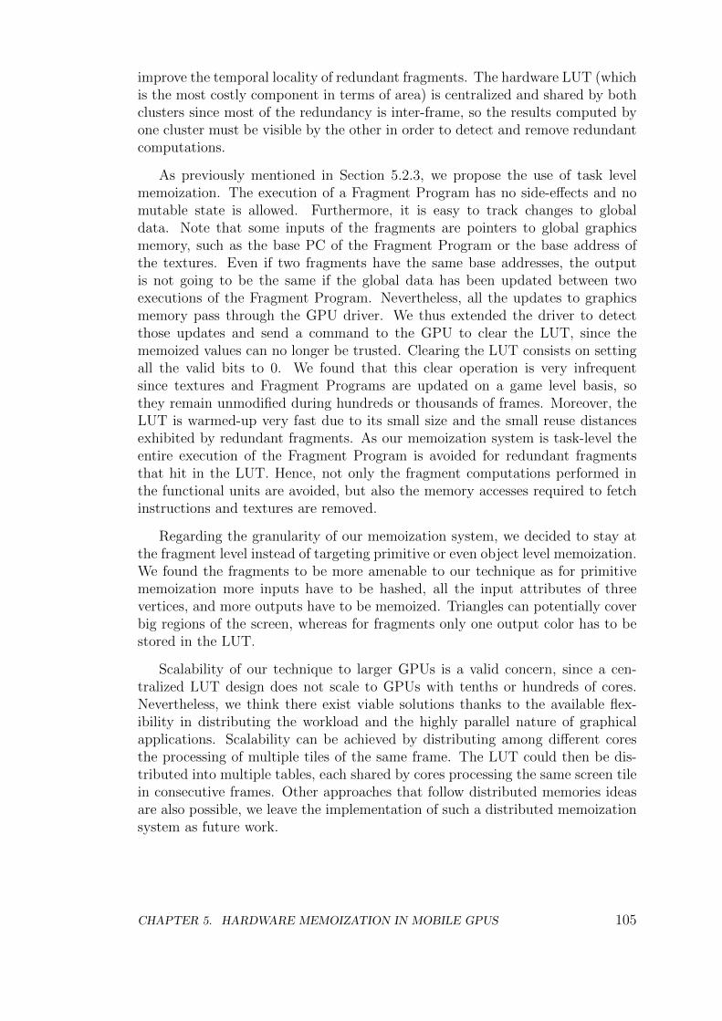
improve the temporal locality of redundant fragments. The hardware LUT (whichis the most costly component in terms of area) is centralized and shared by bothclusters since most of the redundancy is inter-frame, so the results computed byone cluster must be visible by the other in order to detect and remove redundantcomputations.
As previously mentioned in Section 5.2.3, we propose the use of task levelmemoization. The execution of a Fragment Program has no side-effects and nomutable state is allowed. Furthermore, it is easy to track changes to globaldata. Note that some inputs of the fragments are pointers to global graphicsmemory, such as the base PC of the Fragment Program or the base address ofthe textures. Even if two fragments have the same base addresses, the outputis not going to be the same if the global data has been updated between twoexecutions of the Fragment Program. Nevertheless, all the updates to graphicsmemory pass through the GPU driver. We thus extended the driver to detectthose updates and send a command to the GPU to clear the LUT, since thememoized values can no longer be trusted. Clearing the LUT consists on settingall the valid bits to 0. We found that this clear operation is very infrequentsince textures and Fragment Programs are updated on a game level basis, sothey remain unmodified during hundreds or thousands of frames. Moreover, theLUT is warmed-up very fast due to its small size and the small reuse distancesexhibited by redundant fragments. As our memoization system is task-level theentire execution of the Fragment Program is avoided for redundant fragmentsthat hit in the LUT. Hence, not only the fragment computations performed inthe functional units are avoided, but also the memory accesses required to fetchinstructions and textures are removed.
Regarding the granularity of our memoization system, we decided to stay atthe fragment level instead of targeting primitive or even object level memoization.We found the fragments to be more amenable to our technique as for primitivememoization more inputs have to be hashed, all the input attributes of threevertices, and more outputs have to be memoized. Triangles can potentially coverbig regions of the screen, whereas for fragments only one output color has to bestored in the LUT.
Scalability of our technique to larger GPUs is a valid concern, since a cen-tralized LUT design does not scale to GPUs with tenths or hundreds of cores.Nevertheless, we think there exist viable solutions thanks to the available flex-ibility in distributing the workload and the highly parallel nature of graphicalapplications. Scalability can be achieved by distributing among different coresthe processing of multiple tiles of the same frame. The LUT could then be dis-tributed into multiple tables, each shared by cores processing the same screen tilein consecutive frames. Other approaches that follow distributed memories ideasare also possible, we leave the implementation of such a distributed memoizationsystem as future work.
CHAPTER 5. HARDWARE MEMOIZATION IN MOBILE GPUS 105
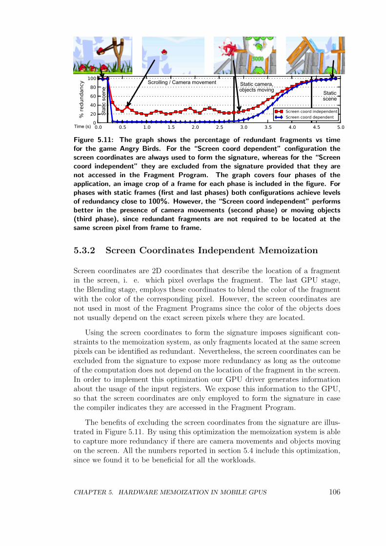
0.0 0.5 1.0 1.5 2.0 2.5 3.0 3.5 4.0 4.5 5.00
20406080
100%
redu
ndan
cy
Screen coord independentScreen coord dependent
Time (s)
Stat
ic s
cene
Scrolling / Camera movement Static camera,objects moving Static
scene
Figure 5.11: The graph shows the percentage of redundant fragments vs timefor the game Angry Birds. For the “Screen coord dependent” configuration thescreen coordinates are always used to form the signature, whereas for the “Screencoord independent” they are excluded from the signature provided that they arenot accessed in the Fragment Program. The graph covers four phases of theapplication, an image crop of a frame for each phase is included in the figure. Forphases with static frames (first and last phases) both configurations achieve levelsof redundancy close to 100%. However, the “Screen coord independent” performsbetter in the presence of camera movements (second phase) or moving objects(third phase), since redundant fragments are not required to be located at thesame screen pixel from frame to frame.
5.3.2 Screen Coordinates Independent Memoization
Screen coordinates are 2D coordinates that describe the location of a fragmentin the screen, i. e. which pixel overlaps the fragment. The last GPU stage,the Blending stage, employs these coordinates to blend the color of the fragmentwith the color of the corresponding pixel. However, the screen coordinates arenot used in most of the Fragment Programs since the color of the objects doesnot usually depend on the exact screen pixels where they are located.
Using the screen coordinates to form the signature imposes significant con-straints to the memoization system, as only fragments located at the same screenpixels can be identified as redundant. Nevertheless, the screen coordinates can beexcluded from the signature to expose more redundancy as long as the outcomeof the computation does not depend on the location of the fragment in the screen.In order to implement this optimization our GPU driver generates informationabout the usage of the input registers. We expose this information to the GPU,so that the screen coordinates are only employed to form the signature in casethe compiler indicates they are accessed in the Fragment Program.
The benefits of excluding the screen coordinates from the signature are illus-trated in Figure 5.11. By using this optimization the memoization system is ableto capture more redundancy if there are camera movements and objects movingon the screen. All the numbers reported in section 5.4 include this optimization,since we found it to be beneficial for all the workloads.
CHAPTER 5. HARDWARE MEMOIZATION IN MOBILE GPUS 106
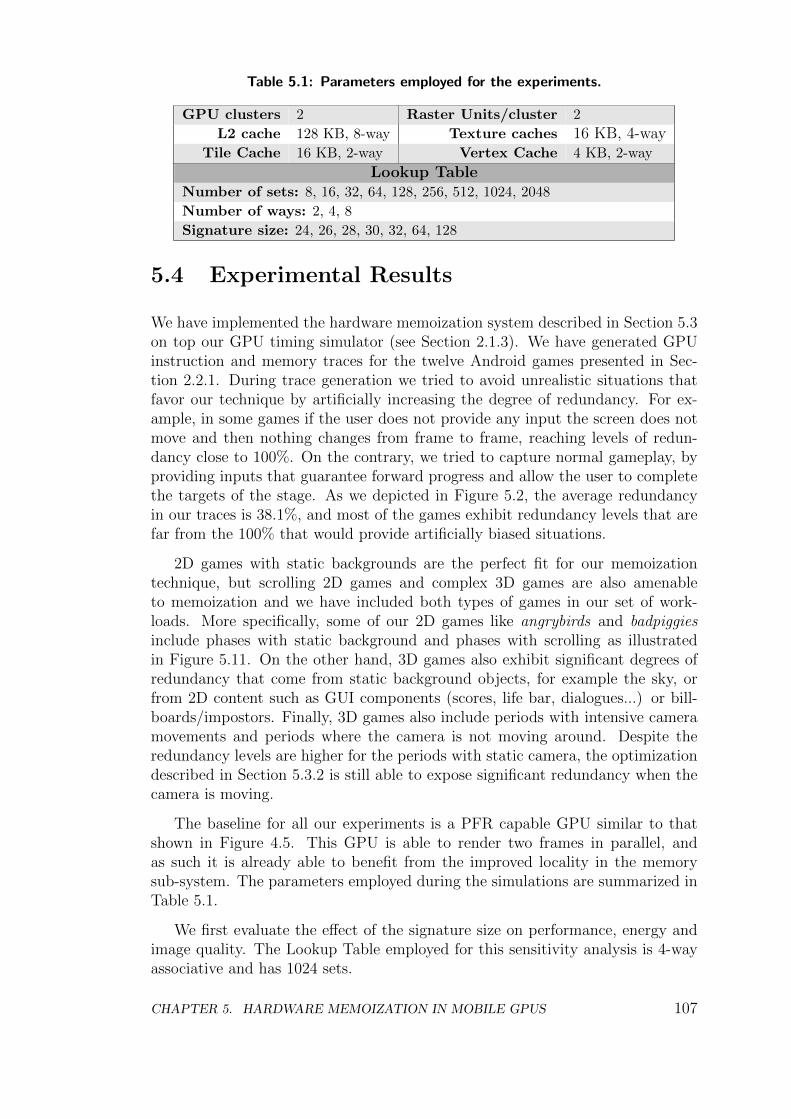
Table 5.1: Parameters employed for the experiments.
GPU clusters 2 Raster Units/cluster 2
L2 cache 128 KB, 8-way Texture caches 16 KB, 4-wayTile Cache 16 KB, 2-way Vertex Cache 4 KB, 2-way
Lookup TableNumber of sets: 8, 16, 32, 64, 128, 256, 512, 1024, 2048
Number of ways: 2, 4, 8
Signature size: 24, 26, 28, 30, 32, 64, 128
5.4 Experimental Results
We have implemented the hardware memoization system described in Section 5.3on top our GPU timing simulator (see Section 2.1.3). We have generated GPUinstruction and memory traces for the twelve Android games presented in Sec-tion 2.2.1. During trace generation we tried to avoid unrealistic situations thatfavor our technique by artificially increasing the degree of redundancy. For ex-ample, in some games if the user does not provide any input the screen does notmove and then nothing changes from frame to frame, reaching levels of redun-dancy close to 100%. On the contrary, we tried to capture normal gameplay, byproviding inputs that guarantee forward progress and allow the user to completethe targets of the stage. As we depicted in Figure 5.2, the average redundancyin our traces is 38.1%, and most of the games exhibit redundancy levels that arefar from the 100% that would provide artificially biased situations.
2D games with static backgrounds are the perfect fit for our memoizationtechnique, but scrolling 2D games and complex 3D games are also amenableto memoization and we have included both types of games in our set of work-loads. More specifically, some of our 2D games like angrybirds and badpiggiesinclude phases with static background and phases with scrolling as illustratedin Figure 5.11. On the other hand, 3D games also exhibit significant degrees ofredundancy that come from static background objects, for example the sky, orfrom 2D content such as GUI components (scores, life bar, dialogues...) or bill-boards/impostors. Finally, 3D games also include periods with intensive cameramovements and periods where the camera is not moving around. Despite theredundancy levels are higher for the periods with static camera, the optimizationdescribed in Section 5.3.2 is still able to expose significant redundancy when thecamera is moving.
The baseline for all our experiments is a PFR capable GPU similar to thatshown in Figure 4.5. This GPU is able to render two frames in parallel, andas such it is already able to benefit from the improved locality in the memorysub-system. The parameters employed during the simulations are summarized inTable 5.1.
We first evaluate the effect of the signature size on performance, energy andimage quality. The Lookup Table employed for this sensitivity analysis is 4-wayassociative and has 1024 sets.
CHAPTER 5. HARDWARE MEMOIZATION IN MOBILE GPUS 107
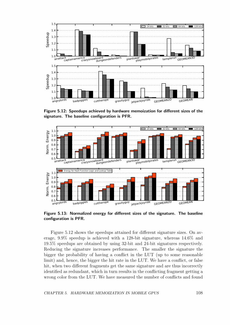
1.0
1.1
1.2
1.3
1.4
1.5
Spee
dup
airattackcaptainamerica
crazysnowboarddungeondefenders plantswar
playmobilpirates templerunGEOMEAN3D
24 bits 32 bits 64 bits 128 bits
1.0
1.1
1.2
1.3
1.4
1.5
Spee
dup
angrybirds badpiggies cuttherope gravityguyjetpackjoyride
GEOMEAN2D GEOMEAN
Figure 5.12: Speedups achieved by hardware memoization for different sizes of thesignature. The baseline configuration is PFR.
0.50.60.70.80.91.01.1
Norm
. Ene
rgy
airattackcaptainamerica
crazysnowboarddungeondefenders plantswar
playmobilpirates templerunGEOMEAN3D
24 bits 32 bits 64 bits 128 bits
0.50.60.70.80.91.01.1
Norm
. Ene
rgy
angrybirds badpiggies cuttherope gravityguyjetpackjoyride
GEOMEAN2D GEOMEAN
Energy for Hash Function Logic and Lookup Table
Figure 5.13: Normalized energy for different sizes of the signature. The baselineconfiguration is PFR.
Figure 5.12 shows the speedups attained for different signature sizes. On av-erage, 9.9% speedup is achieved with a 128-bit signature, whereas 14.6% and19.5% speedups are obtained by using 32-bit and 24-bit signatures respectively.Reducing the signature increases performance. The smaller the signature thebigger the probability of having a conflict in the LUT (up to some reasonablelimit) and, hence, the bigger the hit rate in the LUT. We have a conflict, or falsehit, when two different fragments get the same signature and are thus incorrectlyidentified as redundant, which in turn results in the conflicting fragment getting awrong color from the LUT. We have measured the number of conflicts and found
CHAPTER 5. HARDWARE MEMOIZATION IN MOBILE GPUS 108
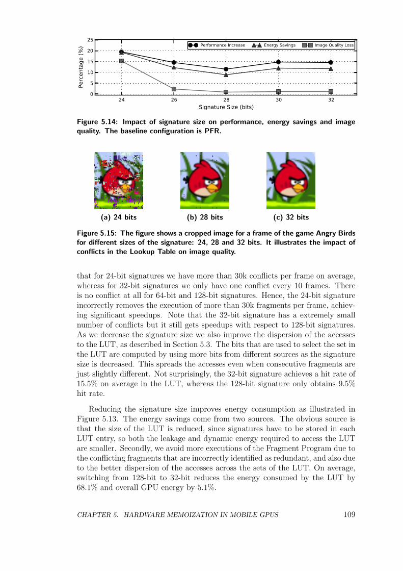
24 26 28 30 32Signature Size (bits)
0
5
10
15
20
25
Perc
enta
ge (%
) Performance Increase Energy Savings Image Quality Loss
Figure 5.14: Impact of signature size on performance, energy savings and imagequality. The baseline configuration is PFR.
(a) 24 bits (b) 28 bits (c) 32 bits
Figure 5.15: The figure shows a cropped image for a frame of the game Angry Birdsfor different sizes of the signature: 24, 28 and 32 bits. It illustrates the impact ofconflicts in the Lookup Table on image quality.
that for 24-bit signatures we have more than 30k conflicts per frame on average,whereas for 32-bit signatures we only have one conflict every 10 frames. Thereis no conflict at all for 64-bit and 128-bit signatures. Hence, the 24-bit signatureincorrectly removes the execution of more than 30k fragments per frame, achiev-ing significant speedups. Note that the 32-bit signature has a extremely smallnumber of conflicts but it still gets speedups with respect to 128-bit signatures.As we decrease the signature size we also improve the dispersion of the accessesto the LUT, as described in Section 5.3. The bits that are used to select the set inthe LUT are computed by using more bits from different sources as the signaturesize is decreased. This spreads the accesses even when consecutive fragments arejust slightly different. Not surprisingly, the 32-bit signature achieves a hit rate of15.5% on average in the LUT, whereas the 128-bit signature only obtains 9.5%hit rate.
Reducing the signature size improves energy consumption as illustrated inFigure 5.13. The energy savings come from two sources. The obvious source isthat the size of the LUT is reduced, since signatures have to be stored in eachLUT entry, so both the leakage and dynamic energy required to access the LUTare smaller. Secondly, we avoid more executions of the Fragment Program due tothe conflicting fragments that are incorrectly identified as redundant, and also dueto the better dispersion of the accesses across the sets of the LUT. On average,switching from 128-bit to 32-bit reduces the energy consumed by the LUT by68.1% and overall GPU energy by 5.1%.
CHAPTER 5. HARDWARE MEMOIZATION IN MOBILE GPUS 109
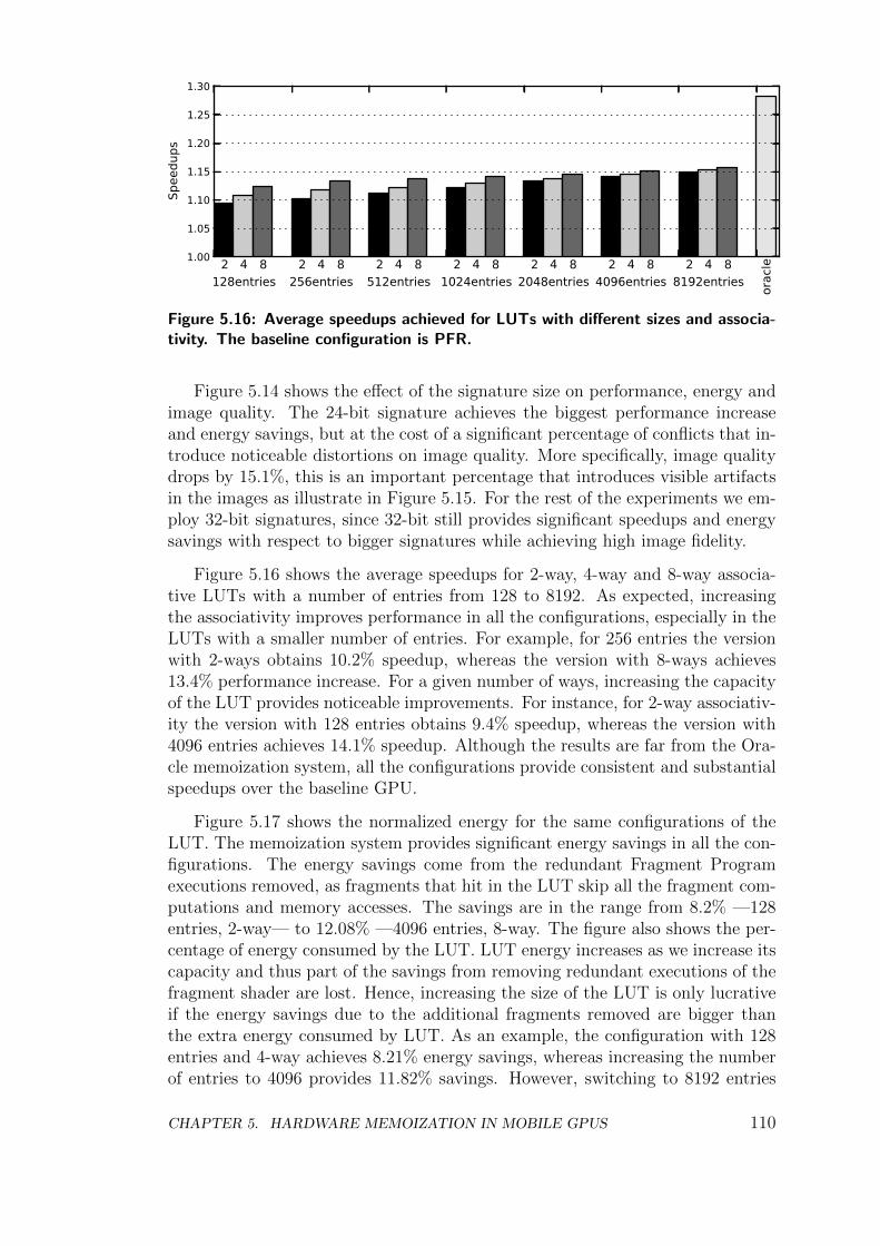
1.00
1.05
1.10
1.15
1.20
1.25
1.30
Spee
dups
128entries 256entries 512entries 1024entries 2048entries 4096entries 8192entries orac
le2 2 2 2 2 2 24 4 4 4 4 4 48 8 8 8 8 8 8
Figure 5.16: Average speedups achieved for LUTs with different sizes and associa-tivity. The baseline configuration is PFR.
Figure 5.14 shows the effect of the signature size on performance, energy andimage quality. The 24-bit signature achieves the biggest performance increaseand energy savings, but at the cost of a significant percentage of conflicts that in-troduce noticeable distortions on image quality. More specifically, image qualitydrops by 15.1%, this is an important percentage that introduces visible artifactsin the images as illustrate in Figure 5.15. For the rest of the experiments we em-ploy 32-bit signatures, since 32-bit still provides significant speedups and energysavings with respect to bigger signatures while achieving high image fidelity.
Figure 5.16 shows the average speedups for 2-way, 4-way and 8-way associa-tive LUTs with a number of entries from 128 to 8192. As expected, increasingthe associativity improves performance in all the configurations, especially in theLUTs with a smaller number of entries. For example, for 256 entries the versionwith 2-ways obtains 10.2% speedup, whereas the version with 8-ways achieves13.4% performance increase. For a given number of ways, increasing the capacityof the LUT provides noticeable improvements. For instance, for 2-way associativ-ity the version with 128 entries obtains 9.4% speedup, whereas the version with4096 entries achieves 14.1% speedup. Although the results are far from the Ora-cle memoization system, all the configurations provide consistent and substantialspeedups over the baseline GPU.
Figure 5.17 shows the normalized energy for the same configurations of theLUT. The memoization system provides significant energy savings in all the con-figurations. The energy savings come from the redundant Fragment Programexecutions removed, as fragments that hit in the LUT skip all the fragment com-putations and memory accesses. The savings are in the range from 8.2% —128entries, 2-way— to 12.08% —4096 entries, 8-way. The figure also shows the per-centage of energy consumed by the LUT. LUT energy increases as we increase itscapacity and thus part of the savings from removing redundant executions of thefragment shader are lost. Hence, increasing the size of the LUT is only lucrativeif the energy savings due to the additional fragments removed are bigger thanthe extra energy consumed by LUT. As an example, the configuration with 128entries and 4-way achieves 8.21% energy savings, whereas increasing the numberof entries to 4096 provides 11.82% savings. However, switching to 8192 entries
CHAPTER 5. HARDWARE MEMOIZATION IN MOBILE GPUS 110
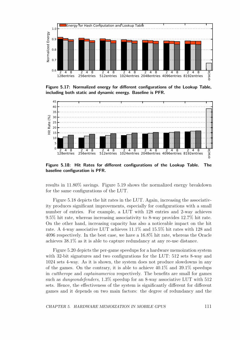
0.6
0.7
0.8
0.9
1.0
Norm
aliz
ed E
nerg
y
128entries 256entries 512entries 1024entries 2048entries 4096entries 8192entries
orac
le2 2 2 2 2 2 24 4 4 4 4 4 48 8 8 8 8 8 8
Energy for Hash Computation and Lookup Table
Figure 5.17: Normalized energy for different configurations of the Lookup Table,including both static and dynamic energy. Baseline is PFR.
05
1015202530354045
Hit R
ate
(%)
128entries 256entries 512entries 1024entries 2048entries 4096entries 8192entries
orac
le2 2 2 2 2 2 24 4 4 4 4 4 48 8 8 8 8 8 8
Figure 5.18: Hit Rates for different configurations of the Lookup Table. Thebaseline configuration is PFR.
results in 11.80% savings. Figure 5.19 shows the normalized energy breakdownfor the same configurations of the LUT.
Figure 5.18 depicts the hit rates in the LUT. Again, increasing the associativ-ity produces significant improvements, especially for configurations with a smallnumber of entries. For example, a LUT with 128 entries and 2-way achieves9.5% hit rate, whereas increasing associativity to 8-way provides 12.7% hit rate.On the other hand, increasing capacity has also a noticeable impact on the hitrate. A 4-way associative LUT achieves 11.1% and 15.5% hit rates with 128 and4096 respectively. In the best case, we have a 16.8% hit rate, whereas the Oracleachieves 38.1% as it is able to capture redundancy at any re-use distance.
Figure 5.20 depicts the per-game speedups for a hardware memoization systemwith 32-bit signatures and two configurations for the LUT: 512 sets 8-way and1024 sets 4-way. As it is shown, the system does not produce slowdowns in anyof the games. On the contrary, it is able to achieve 40.1% and 39.1% speedupsin cuttherope and captainamerica respectively. The benefits are small for gamessuch as dungeondefenders, 1.3% speedup for an 8-way associative LUT with 512sets. Hence, the effectiveness of the system is significantly different for differentgames and it depends on two main factors: the degree of redundancy and the
CHAPTER 5. HARDWARE MEMOIZATION IN MOBILE GPUS 111
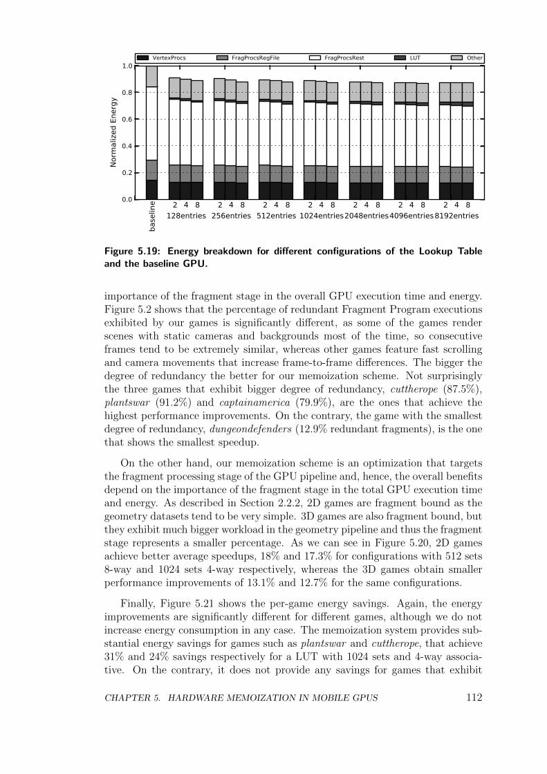
0.0
0.2
0.4
0.6
0.8
1.0
Norm
aliz
ed E
nerg
y
base
line
128entries2 4 8
256entries2 4 8
512entries2 4 8
1024entries2 4 8
2048entries2 4 8
4096entries2 4 8
8192entries2 4 8
VertexProcs FragProcsRegFile FragProcsRest LUT Other
Figure 5.19: Energy breakdown for different configurations of the Lookup Tableand the baseline GPU.
importance of the fragment stage in the overall GPU execution time and energy.Figure 5.2 shows that the percentage of redundant Fragment Program executionsexhibited by our games is significantly different, as some of the games renderscenes with static cameras and backgrounds most of the time, so consecutiveframes tend to be extremely similar, whereas other games feature fast scrollingand camera movements that increase frame-to-frame differences. The bigger thedegree of redundancy the better for our memoization scheme. Not surprisinglythe three games that exhibit bigger degree of redundancy, cuttherope (87.5%),plantswar (91.2%) and captainamerica (79.9%), are the ones that achieve thehighest performance improvements. On the contrary, the game with the smallestdegree of redundancy, dungeondefenders (12.9% redundant fragments), is the onethat shows the smallest speedup.
On the other hand, our memoization scheme is an optimization that targetsthe fragment processing stage of the GPU pipeline and, hence, the overall benefitsdepend on the importance of the fragment stage in the total GPU execution timeand energy. As described in Section 2.2.2, 2D games are fragment bound as thegeometry datasets tend to be very simple. 3D games are also fragment bound, butthey exhibit much bigger workload in the geometry pipeline and thus the fragmentstage represents a smaller percentage. As we can see in Figure 5.20, 2D gamesachieve better average speedups, 18% and 17.3% for configurations with 512 sets8-way and 1024 sets 4-way respectively, whereas the 3D games obtain smallerperformance improvements of 13.1% and 12.7% for the same configurations.
Finally, Figure 5.21 shows the per-game energy savings. Again, the energyimprovements are significantly different for different games, although we do notincrease energy consumption in any case. The memoization system provides sub-stantial energy savings for games such as plantswar and cuttherope, that achieve31% and 24% savings respectively for a LUT with 1024 sets and 4-way associa-tive. On the contrary, it does not provide any savings for games that exhibit
CHAPTER 5. HARDWARE MEMOIZATION IN MOBILE GPUS 112
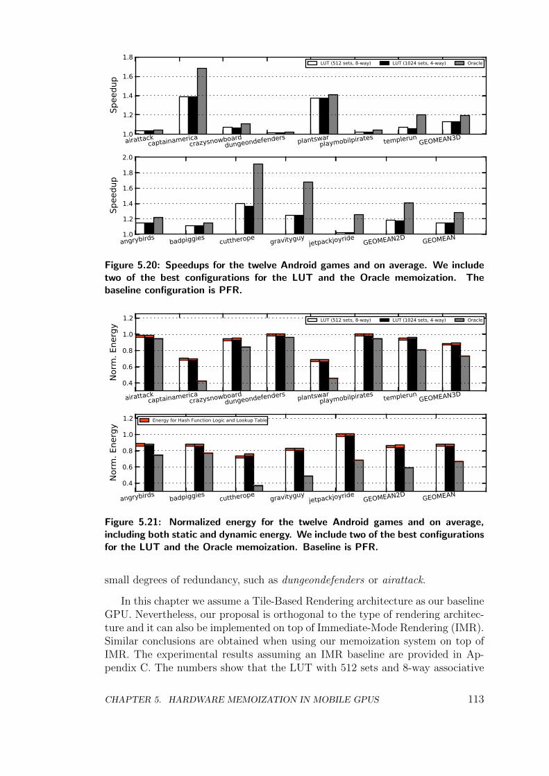
1.0
1.2
1.4
1.6
1.8
Spee
dup
airattackcaptainamerica
crazysnowboarddungeondefenders plantswar
playmobilpirates templerunGEOMEAN3D
LUT (512 sets, 8-way) LUT (1024 sets, 4-way) Oracle
1.0
1.2
1.4
1.6
1.8
2.0
Spee
dup
angrybirds badpiggies cuttherope gravityguyjetpackjoyride
GEOMEAN2D GEOMEAN
Figure 5.20: Speedups for the twelve Android games and on average. We includetwo of the best configurations for the LUT and the Oracle memoization. Thebaseline configuration is PFR.
0.4
0.6
0.8
1.0
1.2
Norm
. Ene
rgy
airattackcaptainamerica
crazysnowboarddungeondefenders plantswar
playmobilpirates templerunGEOMEAN3D
LUT (512 sets, 8-way) LUT (1024 sets, 4-way) Oracle
0.4
0.6
0.8
1.0
1.2
Norm
. Ene
rgy
angrybirds badpiggies cuttherope gravityguyjetpackjoyride
GEOMEAN2D GEOMEAN
Energy for Hash Function Logic and Lookup Table
Figure 5.21: Normalized energy for the twelve Android games and on average,including both static and dynamic energy. We include two of the best configurationsfor the LUT and the Oracle memoization. Baseline is PFR.
small degrees of redundancy, such as dungeondefenders or airattack.
In this chapter we assume a Tile-Based Rendering architecture as our baselineGPU. Nevertheless, our proposal is orthogonal to the type of rendering architec-ture and it can also be implemented on top of Immediate-Mode Rendering (IMR).Similar conclusions are obtained when using our memoization system on top ofIMR. The experimental results assuming an IMR baseline are provided in Ap-pendix C. The numbers show that the LUT with 512 sets and 8-way associative
CHAPTER 5. HARDWARE MEMOIZATION IN MOBILE GPUS 113
achieves 16.4% speedup and 13% energy savings.
5.5 Conclusions
In this Chapter we have shown that more than 38% of the fragment programexecutions are redundant on average for a set of Android games, suggesting thatmemoization can be useful to reuse computations in order to save time and energy.However, fragment memoization is no simple task. As we have shown most of theredundancy that could be exploited exists across frames.
We thus proposed to employ fragment memoization on top of techniques thataim to reduce the inter-frame re-use distances of fragments, such as ParallelFrame Rendering (PFR). When we employ PFR, 68.8% of the redundant frag-ments are brought into re-use distances that make them amenable to hardwarememoization. Our memoization scheme is able to achieve significant benefits inboth performance and power, with minimal distortion of the frames that are cap-tured. More specifically, when compared with a state-of-art PFR-enabled GPU,our scheme is able to remove enough computation to achieve 15% speedup for aset of commercial Android games. This improves the energy consumption of thesystem by 12% on average. All this, comes at a negligible cost in terms of imagedistortion, which as shown in Section 5.4 is not perceivable.
CHAPTER 5. HARDWARE MEMOIZATION IN MOBILE GPUS 114
Chapter 6
Conclusions
In this chapter the main conclusions and contributions of this thesis are presented,as well as some open-research areas for future work.
6.1 Conclusions
A complete and comprehensive analysis of mobile graphics processors has beenmade, together with an evaluation of multiple energy saving techniques for low-power GPUs, yielding the following main conclusions.
In first place, the results obtained by using a cycle-accurate GPU simula-tor and several commercial Android applications indicate that multithreadingand prefetching are effective techniques for tolerating memory latency, but notenergy-efficient. Massive multithreading requires huge register files that increaseenergy consumption, whereas prefetching accuracy is relatively low due to theunpredictable texture fetches. The access-execute paradigm provides a more ef-ficient solution to bridge the memory gap, as it requires simple hardware andit is based on computed addresses rather than predicted addresses to maximizeprefetch accuracy. The experimental results presented in this thesis show thata small degree of multithreading combined with a decoupled access/execute-likearchitecture provides the most energy efficient solution to hide the memory la-tency. More specifically, the decoupled access/execute-like design with 4 SIMDthreads/processor is able to achieve 97% of the performance of a larger GPU with16 SIMD threads/processor, while providing 20.5% energy savings.
In second place, the energy numbers obtained by using our GPU power modelshow that the off-chip memory accesses to system memory are one of the mainsources of energy consumption in a mobile GPU, thereby supporting the resultspresented in previous research work. The analysis of bandwidth usage in severalAndroid games reveals that most of the memory bandwidth is typically employedfor fetching textures. Furthermore, consecutive frames tend to be extremelysimilar, sharing most of the texture dataset. However, the GPU cannot exploit
CHAPTER 6. CONCLUSIONS 115
this inter-frame texture re-use due to the big size of the texture dataset for oneframe.
Parallel Frame Rendering (PFR) is a bandwidth saving technique designedwith the aim of capturing the inter-frame texture re-use by overlapping the ex-ecution of consecutive frames. PFR splits the GPU in two clusters that processtwo consecutive frames in parallel. Both clusters share texture data via the L2cache, so textures are fetched from system memory just once every two framesinstead of being fetched on a frame basis, saving memory bandwidth. This, how-ever, comes at a cost in the responsiveness of the system, since rendering eachframe takes twice the time as it is generated with half of the resources, increasinginput lag.
Adaptive forms of PFR can be employed to trade responsiveness for energyefficiency. The analysis of user interaction in mobile games shows that the userdoes not provide any input most of the time. In addition, user inputs tend tobe heavily clustered: mobile games exhibit short phases with user inputs andlong phases where the user does not provide any input. PFR can be extensivelyemployed during phases without user inputs, where input lag is not a problem.The reactive versions of PFR achieve high responsiveness while providing 23.8%reduction in off-chip memory traffic, that results in 12% speedup and 20.1%energy savings on average.
In third place, an analysis of redundancy in mobile games reveals that morethan 38% of the Fragment Program executions are redundant on average, sug-gesting that memoization can be effective to reuse computations in order to savetime and energy. However, capturing this redundancy is not an easy task as mostof the redundancy that could be exploited exists across frames at huge re-usedistances, rendering most of hardware-based approaches unfeasible.
A fragment memoization system can be architected on top of techniques thataim to reduce the inter-frame re-use distances of fragments, such as the afore-mentioned PFR. Under PFR, 68.8% of the redundant fragments are brought intore-use distances that make them amenable for hardware memoization. A memo-ization system based on a small hardware Look Up Table achieves 15% speedupover a state-of-the-art PFR-enabled GPU, reducing energy consumption by 12%on average.
In summary, the experimental results presented in this thesis show that decou-pled access/execute architectures, combined with a small degree of multithread-ing, provide the most energy-efficient solution for hiding the memory latency in amobile GPU. Furthermore, using PFR to execute multiple frames in parallel pro-vides noticeable energy savings that come from a significant reduction in memorybandwidth usage, as consecutive frames tend to be extremely similar and thusthey share most of the texture dataset. GPU energy consumption can be fur-ther improved by using a memoization scheme on top of PFR to avoid redundantexecutions of the Fragment Program.
CHAPTER 6. CONCLUSIONS 116
6.2 Contributions
In this dissertation different energy saving techniques for mobile graphics proces-sors have been proposed, from the development of energy efficient memory latencytolerance techniques to the design of strategies for optimizing memory bandwidthusage. Furthermore, a mobile GPU simulation infrastructure has been developedas part of this thesis. The contributions obtained through this dissertation aresummarized as follows.
In first place, we propose the migration of GPU designs towards the access-execute paradigm. This thesis introduces a decoupled access/execute-like archi-tecture for the fragment processors of a mobile GPU. In this scheme, all thenecessary data for processing the fragments is prefetched into the texture cacheswhile the fragments are waiting to be dispatched to the fragment processors. Bythe time a fragment is issued all the data required for its processing is hopefullyavailable in the caches, avoiding cache miss stalls to a large extent. The basedecoupled access/execute-like design is further improved by allowing for remotetexture cache requests to exploit the high degree of data sharing among fragmentprocessors. The end-design easily outperforms conventional hardware prefetchingschemes and achieves similar performance to a heavily multithreaded GPU, butconsuming just a fraction of its energy as described in Chapter 3. This workhas been published in the proceedings of the 39th International Symposium onComputer Architecture (ISCA):
• “Boosting Mobile GPU Performance with a Decoupled Access/ExecuteFragment Processor”.Jose-Maria Arnau, Joan-Manuel Parcerisa and Polychronis Xekalakis.International Symposium on Computer Architecture, 2012.
In second place, we propose Parallel Frame Rendering (PFR), a bandwidthsaving technique that overlaps the rendering of consecutive frames. Under PFRthe GPU is split in two clusters that share texture data via the second level sharedcache. The first cluster renders odd frames and the second cluster renders evenframes. By processing two frames in parallel, textures are fetched once every twoframes instead of being fetched on a frame basis as in conventional GPUs, pro-viding significant bandwidth savings. To minimize the impact on responsiveness,different variations of PFR that are reactive to user interaction are proposed inthis thesis. The reactive versions of PFR achieve high responsiveness, while pro-viding significant bandwidth savings that result in improvements in performanceand energy consumption as reported in Chapter 4. This work has been publishedin the proceedings of the 22nd international conference on Parallel Architecturesand Compilation Techniques (PACT):
• “Parallel Frame Rendering: Trading Responsiveness for Energy on a MobileGPU”.Jose-Maria Arnau, Joan-Manuel Parcerisa and Polychronis Xekalakis.
CHAPTER 6. CONCLUSIONS 117
International Conference on Parallel Architectures and Compilation Tech-niques, 2013.
In third place, we provide an analysis of the per-fragment redundancy asseen in commercial Android applications, showing that more than 38% of theFragment Program executions are redundant on average. We propose to exploitthis high degree of redundancy by using a task-level, hardware based memoizationsystem able to identify and skip redundant executions of the Fragment Program.The proposed memoization scheme keeps a hardware structure that computes asignature of all the inputs to a task and caches the values of the correspondingfragments. Subsequent computations form the signature and check against thestored signatures of the memoized fragments. In case of a hit in the hardwarestructure the system skips the execution of the Fragment Program, avoiding allthe corresponding computations and memory accesses. When architected ontop of PFR, a memoization system based on a small hardware Look Up Tableachieves significant performance improvements and energy savings as reportedin Chapter 5. This work has been published in the proceedings of the 41stInternational Symposium on Computer Architecture (ISCA):
• “Eliminating Redundant Fragment Shader Executions on a Mobile GPUvia Hardware Memoization”.Jose-Maria Arnau, Joan-Manuel Parcerisa and Polychronis Xekalakis.International Symposium on Computer Architecture, 2014.
Finally, a mobile GPU simulation infrastructure has been developed as partof this thesis. The simulator is extensively described in Chapter 2. To the bestof our knowledge, this is the first GPU simulator able to run and profile Androidgraphical applications that employ the OpenGL ES API. The simulator consistson a set of tools for evaluating the performance, energy consumption and im-age quality of mobile graphics processors. This infrastructure was presented ina paper published in the proceedings of the 27th International Conference onSupercomputing:
• “TEAPOT: A Toolset for Evaluating Performance, Power and Image Qual-ity on Mobile Graphics Systems”.Jose-Maria Arnau, Joan-Manuel Parcerisa and Polychronis Xekalakis.International Conference on Supercomputing, 2013.
6.3 Open-Research Areas
Mobile graphics processors are a very recent research field that appeared withthe huge expansion of the smartphones and tablets market. The bibliography onmobile GPU energy is not extensive, on the contrary, there is just a relativelysmall number of papers that target smartphones and mobile workloads. Further
CHAPTER 6. CONCLUSIONS 118
research efforts will be necessary to bridge the energy gap in next generationsof smartphones and tablets. It seems that most of the energy savings will comefrom an efficient use of memory bandwidth, as it is stated by previous researchwork and corroborated in this thesis.
An interesting extension of the work proposed in this thesis would be to tryto apply Parallel Frame Rendering (PFR) more aggressively to achieve biggerbandwidth savings. For example, a system could attempt to overlap 8 frames in-stead of just 2 or 4. The main issue in doing so is responsiveness, as the increasein input lag is proportional to the number of frames rendered in parallel if thehardware resources are not increased. The reactive versions of PFR can be em-ployed to achieve high responsiveness, but they suffer from microstuttering sinceswitching between rendering modes requires buffering or dropping several frames.PFR tries to minimize the number of switches to avoid microstuttering, settingrestrictive values for the thresholds that are employed to decide when to switchbetween rendering modes. However, this severely constrains the percentage oftime that frames are overlapped, losing part of the bandwidth savings. Further-more, the stuttering effects are exacerbated as the number of frames rendered inparallel is increased, since more frames have to be buffered or dropped. Moreefficient ways of switching between rendering modes are necessary to increase thenumber of frames rendered in parallel, in order to maximize bandwidth savingswhile maintaining the same levels of user experience.
On the other hand, an interesting extension of the memoization system pre-sented in Chapter 5 would be to try to bridge the gap with the oracle memoizationby capturing redundant fragments at big re-use distances. This would probablyrequire extending the capacity of the Look Up Table (LUT) in some way. Forexample, the system could employ a virtual LUT stored in main memory andcached on-chip. On the other hand, a software based approach could be usedinstead. The LUT could be stored in a texture that would be accessed from thefragment shader to identify redundant computations.
The memoization system could be further improved by allowing the softwareto provide hints to the GPU about the expected degree of redundancy. Thememoization system is very effective for phases of the application where thecamera is not moving, as consecutive frames tend to be very similar and moreredundant computations are captured and avoided. On the contrary, it performsworse in the presence of fast camera movements. As the information about thebehavior of the camera is available in the software, the game engine could exposethis information to the hardware in order to disable memoization when it is knowto be useless, saving energy for accessing the LUT.
In this thesis we focus on optimizing the bandwidth for texture fetching, astextures represent a huge percentage of bandwidth in typical mobile workloads.However, desktop-like games feature more complex scenes with hundreds of thou-sands or even millions of vertices per frame. In case desktop-like games becomepopular in smartphones and tables —something that would require significant im-provements in mobile user interfaces to provide compelling gaming experience—it could be interesting to consider bandwidth optimizations for geometry fetching.
CHAPTER 6. CONCLUSIONS 119
For example, desktop GPUs employ a technique called geometry instancing toefficiently render objects that are repeated in a crowded scene. By using instanc-ing the geometry is sent to the GPU once and employed to render the multiplecopies of the object, saving bandwidth. Geometry instancing could be combinedwith PFR to perform multi-frame instancing: geometry could be fetched onceand employed to render all the instances of the same object in two consecutiveframes to further improve bandwidth savings.
GPGPU research is also an intriguing direction, as it seems it will be widelysupported in the mobile segment. This thesis is focused in graphics workloadsand OpenGL ES since it is the main API for accessing the GPU in smartphonesand tablets. Nevertheless, it could also be interesting to consider energy savingtechniques for OpenCL/CUDA applications in embedded graphics processors.The mobile GPU simulation infrastructure presented in Chapter 2 can be eas-ily extended to support GPGPU applications. The Gallium3D driver, employedfor GPU trace generation in the infrastructure, offers a front-end for OpenCL,GalliumCompute. Although still immature, this front-end could be used to traceOpenCL commands and OpenCL kernels instead of OpenGL ES rendering com-mands and GLSL shaders. On the other hand, the simulator could be updated tosupport the version 3.1 of OpenGL ES. This version provides “compute shaders”,offering a powerful and flexible form of general purpose computation in a mobileGPU, by using the same graphics API and the same GPU driver that is employedfor rendering.
CHAPTER 6. CONCLUSIONS 120
Appendix A
Decoupled Fragment Processoron top of TBR
In chapter 3 we present our decoupled access/execute-like architecture for thefragment processors of a mobile GPU, and we evaluate our proposal on top ofan Immediate-Mode Rendering (IMR) architecture. Nevertheless, our scheme iscompletely orthogonal to the type of rendering architecture and, hence, it canalso be implemented on top of a Tile-Based Rendering (TBR) pipeline like theone illustrated in Figure 2.2.
In this chapter we include the evaluation of our proposal using TBR as ourbaseline GPU instead of IMR. We use the same parameters that we employedfor IMR (Table 3.1), but we configure our GPU timing simulator to model aTBR pipeline. Figures A.1, A.2 and A.3 show the average speedup, normal-ized energy and energy-efficiency respectively. Figure A.4 shows the per-gameenergy-efficiency. As we can see, the decoupled architectures combined with asmall degree of multithreading are the configurations that achieve the highestenergy-efficiency. More specifically, the decoupled architecture with just 2 SIMDthreads/processor achieves 93% of the performance of a larger GPU with 16 SIMDthreads/processor, while providing 28.2% energy savings. This means 29.5% im-provement in energy-efficiency (speedup divided by normalized energy).
APPENDIX A. DECOUPLED FRAGMENT PROCESSOR ON TOP OF TBR 121
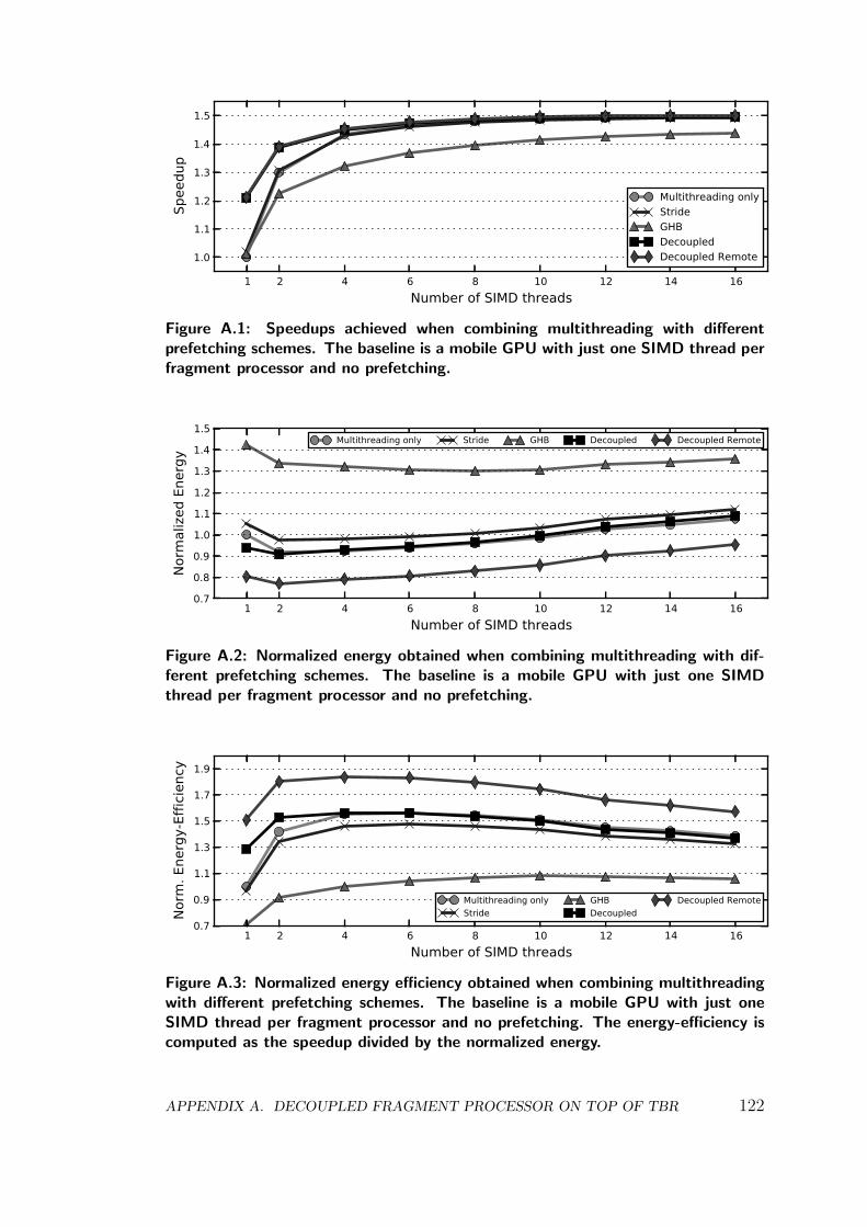
1 2 4 6 8 10 12 14 16Number of SIMD threads
1.0
1.1
1.2
1.3
1.4
1.5
Spee
dup
Multithreading onlyStrideGHBDecoupledDecoupled Remote
Figure A.1: Speedups achieved when combining multithreading with differentprefetching schemes. The baseline is a mobile GPU with just one SIMD thread perfragment processor and no prefetching.
1 2 4 6 8 10 12 14 16Number of SIMD threads
0.7
0.8
0.9
1.0
1.1
1.2
1.3
1.4
1.5
Norm
aliz
ed E
nerg
y
Multithreading only Stride GHB Decoupled Decoupled Remote
Figure A.2: Normalized energy obtained when combining multithreading with dif-ferent prefetching schemes. The baseline is a mobile GPU with just one SIMDthread per fragment processor and no prefetching.
1 2 4 6 8 10 12 14 16Number of SIMD threads
0.7
0.9
1.1
1.3
1.5
1.7
1.9
Norm
. Ene
rgy-
Effic
ienc
y
Multithreading onlyStride
GHBDecoupled
Decoupled Remote
Figure A.3: Normalized energy efficiency obtained when combining multithreadingwith different prefetching schemes. The baseline is a mobile GPU with just oneSIMD thread per fragment processor and no prefetching. The energy-efficiency iscomputed as the speedup divided by the normalized energy.
APPENDIX A. DECOUPLED FRAGMENT PROCESSOR ON TOP OF TBR 122
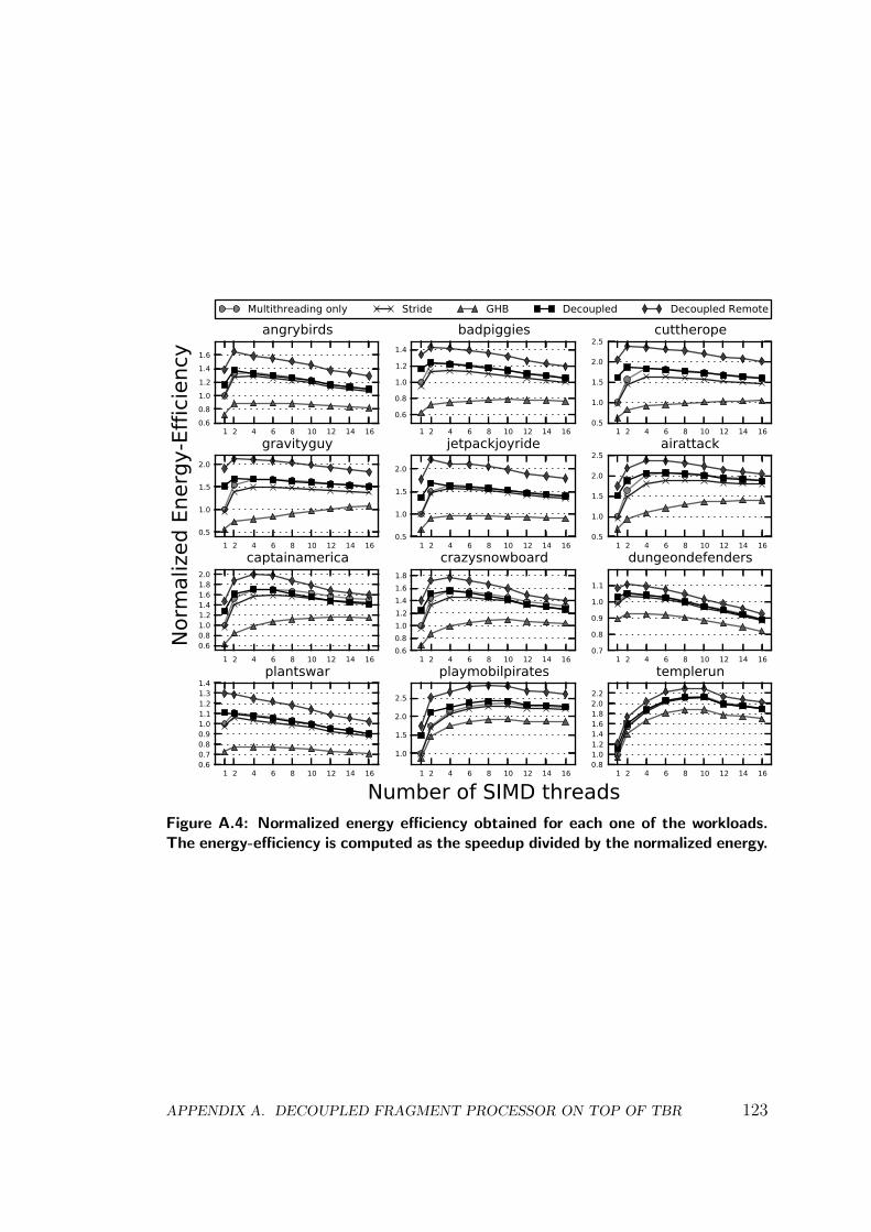
1 2 4 6 8 10 12 14 160.60.81.01.21.41.6
angrybirdsMultithreading only Stride GHB Decoupled Decoupled Remote
1 2 4 6 8 10 12 14 16
0.6
0.8
1.0
1.2
1.4
badpiggies
1 2 4 6 8 10 12 14 160.5
1.0
1.5
2.0
2.5cuttherope
1 2 4 6 8 10 12 14 160.5
1.0
1.5
2.0
Norm
aliz
ed E
nerg
y-Ef
ficie
ncy
gravityguy
1 2 4 6 8 10 12 14 160.5
1.0
1.5
2.0
jetpackjoyride
1 2 4 6 8 10 12 14 160.5
1.0
1.5
2.0
2.5airattack
1 2 4 6 8 10 12 14 160.60.81.01.21.41.61.82.0
captainamerica
1 2 4 6 8 10 12 14 160.60.81.01.21.41.61.8
crazysnowboard
1 2 4 6 8 10 12 14 160.7
0.8
0.9
1.0
1.1
dungeondefenders
1 2 4 6 8 10 12 14 160.60.70.80.91.01.11.21.31.4
plantswar
1 2 4 6 8 10 12 14 16
Number of SIMD threads
1.0
1.5
2.0
2.5
playmobilpirates
1 2 4 6 8 10 12 14 160.81.01.21.41.61.82.02.2
templerun
Figure A.4: Normalized energy efficiency obtained for each one of the workloads.The energy-efficiency is computed as the speedup divided by the normalized energy.
APPENDIX A. DECOUPLED FRAGMENT PROCESSOR ON TOP OF TBR 123

APPENDIX A. DECOUPLED FRAGMENT PROCESSOR ON TOP OF TBR 124
Appendix B
Parallel Frame Rendering on topof IMR
In chapter 4 we present Parallel Frame Rendering (PFR), a memory bandwidthsaving technique that overlaps the processing of multiple frames. We evaluateour proposal assuming a Tile-Based Rendering (TBR) architecture as the base-line GPU. Nevertheless, PFR is completely orthogonal to the type of renderingarchitecture and, hence, it can also be implemented on top of an Immediate-ModeRendering (IMR) pipeline like the one illustrated in Figure 2.2. In this chapter wefirst describe how PFR can be adapted for IMR architectures. Next, we providethe experimental results when assuming an IMR baseline.
PFR processes multiple frames in parallel to optimize memory bandwidthusage for texture fetching, as the texture datasets for consecutive frames tend tobe extremely similar. The GPU is split in two clusters, both clusters sharing thesecond level cache to exploit texture reuse. Therefore, textures are fetched justonce and employed to render the objects in two consecutive frames, instead ofbeing fetched on a frame basis and thus saving bandwidth. The technique is onlyeffective if both clusters access the same textures within a short timespan. In aneffort to maximize texture overlapping, we synchronize both GPU clusters at thetile level —we assume a TBR architecture in chapter 4— so both GPU clusterswork in the same screen tile in two consecutive frames. As the same screen tileusually contains the same objects from frame to frame, tile-level synchronizationprovides a good degree of texture overlapping.
IMR architectures do not split the screen in tiles, they consider the entirescreen at once. Hence, a different strategy to guarantee texture overlapping isnecessary when using an IMR architecture, as we cannot implement tile-level syn-chronization. Since IMR architectures render the scene object by object insteadof tile by tile, we propose to use object-level synchronization and try to renderin parallel objects that use the same textures. Hence, our GPU driver for IMRreschedules the drawing commands issued by the application in order to overlapthe rendering of objects that access the same textures. For every drawing com-mand in the first frame, the GPU driver tries to find a GPU command in the
APPENDIX B. PARALLEL FRAME RENDERING ON TOP OF IMR 125
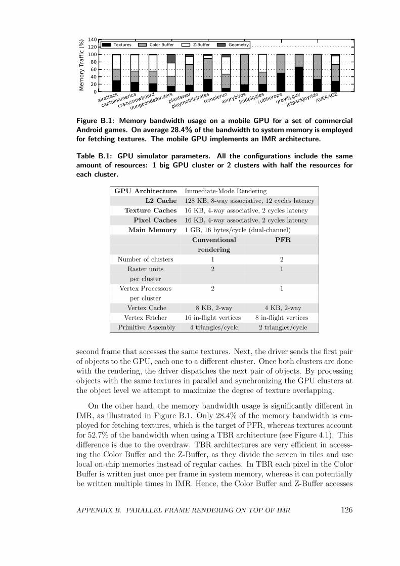
020406080
100120140
Mem
ory
Traf
fic (%
)
airattack
captainamerica
crazysnowboard
dungeondefendersplantswar
playmobilpiratestemplerun
angrybirdsbadpiggies
cuttheropegravityguy
jetpackjoyrideAVERAGE
Textures Color Buffer Z-Buffer Geometry
Figure B.1: Memory bandwidth usage on a mobile GPU for a set of commercialAndroid games. On average 28.4% of the bandwidth to system memory is employedfor fetching textures. The mobile GPU implements an IMR architecture.
Table B.1: GPU simulator parameters. All the configurations include the sameamount of resources: 1 big GPU cluster or 2 clusters with half the resources foreach cluster.
GPU Architecture Immediate-Mode Rendering
L2 Cache 128 KB, 8-way associative, 12 cycles latency
Texture Caches 16 KB, 4-way associative, 2 cycles latency
Pixel Caches 16 KB, 4-way associative, 2 cycles latency
Main Memory 1 GB, 16 bytes/cycle (dual-channel)
Conventional PFR
rendering
Number of clusters 1 2
Raster units 2 1
per cluster
Vertex Processors 2 1
per cluster
Vertex Cache 8 KB, 2-way 4 KB, 2-way
Vertex Fetcher 16 in-flight vertices 8 in-flight vertices
Primitive Assembly 4 triangles/cycle 2 triangles/cycle
second frame that accesses the same textures. Next, the driver sends the first pairof objects to the GPU, each one to a different cluster. Once both clusters are donewith the rendering, the driver dispatches the next pair of objects. By processingobjects with the same textures in parallel and synchronizing the GPU clusters atthe object level we attempt to maximize the degree of texture overlapping.
On the other hand, the memory bandwidth usage is significantly different inIMR, as illustrated in Figure B.1. Only 28.4% of the memory bandwidth is em-ployed for fetching textures, which is the target of PFR, whereas textures accountfor 52.7% of the bandwidth when using a TBR architecture (see Figure 4.1). Thisdifference is due to the overdraw. TBR architectures are very efficient in access-ing the Color Buffer and the Z-Buffer, as they divide the screen in tiles and uselocal on-chip memories instead of regular caches. In TBR each pixel in the ColorBuffer is written just once per frame in system memory, whereas it can potentiallybe written multiple times in IMR. Hence, the Color Buffer and Z-Buffer accesses
APPENDIX B. PARALLEL FRAME RENDERING ON TOP OF IMR 126
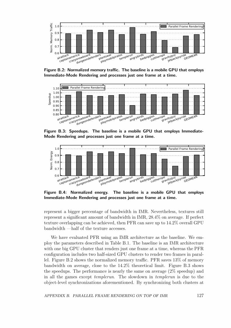
0.6
0.7
0.8
0.9
1.0
Norm
. Mem
ory
Traf
fic
airattack
captainamerica
crazysnowboard
dungeondefendersplantswar
playmobilpiratestemplerun
angrybirdsbadpiggies
cuttheropegravityguy
jetpackjoyrideGEOMEAN
Parallel Frame Rendering
Figure B.2: Normalized memory traffic. The baseline is a mobile GPU that employsImmediate-Mode Rendering and processes just one frame at a time.
0.800.850.900.951.001.051.10
Spee
dup
airattack
captainamerica
crazysnowboard
dungeondefendersplantswar
playmobilpiratestemplerun
angrybirdsbadpiggies
cuttheropegravityguy
jetpackjoyrideGEOMEAN
Parallel Frame Rendering
Figure B.3: Speedups. The baseline is a mobile GPU that employs Immediate-Mode Rendering and processes just one frame at a time.
0.6
0.7
0.8
0.9
1.0
Norm
. Ene
rgy
airattack
captainamerica
crazysnowboard
dungeondefendersplantswar
playmobilpiratestemplerun
angrybirdsbadpiggies
cuttheropegravityguy
jetpackjoyrideGEOMEAN
Parallel Frame Rendering
Figure B.4: Normalized energy. The baseline is a mobile GPU that employsImmediate-Mode Rendering and processes just one frame at a time.
represent a bigger percentage of bandwidth in IMR. Nevertheless, textures stillrepresent a significant amount of bandwidth in IMR, 28.4% on average. If perfecttexture overlapping can be achieved, then PFR can save up to 14.2% overall GPUbandwidth —half of the texture accesses.
We have evaluated PFR using an IMR architecture as the baseline. We em-ploy the parameters described in Table B.1. The baseline is an IMR architecturewith one big GPU cluster that renders just one frame at a time, whereas the PFRconfiguration includes two half-sized GPU clusters to render two frames in paral-lel. Figure B.2 shows the normalized memory traffic. PFR saves 13% of memorybandwidth on average, close to the 14.2% theoretical limit. Figure B.3 showsthe speedups. The performance is nearly the same on average (2% speedup) andin all the games except templerun. The slowdown in templerun is due to theobject-level synchronizations aforementioned. By synchronizing both clusters at
APPENDIX B. PARALLEL FRAME RENDERING ON TOP OF IMR 127
the object level we maximize texture overlapping. However, if the two objectsrendered in parallel exhibit significantly different workload, then the synchro-nizations introduce workload imbalances that affect performance. This issue canbe solved by avoiding the synchronization in case of workload imbalance, or byimproving the scheduling of the commands in order to process in parallel objectswith similar workload. We leave this improvement as future work. Finally, Fig-ure B.4 shows the normalized energy. PFR saves 10% of overall GPU energy onaverage.
APPENDIX B. PARALLEL FRAME RENDERING ON TOP OF IMR 128
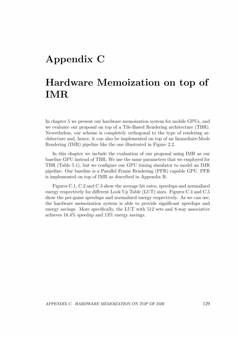
Appendix C
Hardware Memoization on top ofIMR
In chapter 5 we present our hardware memoization system for mobile GPUs, andwe evaluate our proposal on top of a Tile-Based Rendering architecture (TBR).Nevertheless, our scheme is completely orthogonal to the type of rendering ar-chitecture and, hence, it can also be implemented on top of an Immediate-ModeRendering (IMR) pipeline like the one illustrated in Figure 2.2.
In this chapter we include the evaluation of our proposal using IMR as ourbaseline GPU instead of TBR. We use the same parameters that we employed forTBR (Table 5.1), but we configure our GPU timing simulator to model an IMRpipeline. Our baseline is a Parallel Frame Rendering (PFR) capable GPU. PFRis implemented on top of IMR as described in Appendix B.
Figures C.1, C.2 and C.3 show the average hit rates, speedups and normalizedenergy respectively for different Look Up Table (LUT) sizes. Figures C.4 and C.5show the per-game speedups and normalized energy respectively. As we can see,the hardware memoization system is able to provide significant speedups andenergy savings. More specifically, the LUT with 512 sets and 8-way associativeachieves 16.4% speedup and 13% energy savings.
APPENDIX C. HARDWARE MEMOIZATION ON TOP OF IMR 129
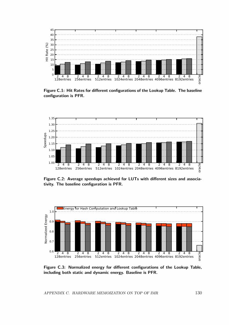
05
1015202530354045
Hit R
ate
(%)
128entries 256entries 512entries 1024entries 2048entries 4096entries 8192entries
orac
le2 2 2 2 2 2 24 4 4 4 4 4 48 8 8 8 8 8 8
Figure C.1: Hit Rates for different configurations of the Lookup Table. The baselineconfiguration is PFR.
1.00
1.05
1.10
1.15
1.20
1.25
1.30
1.35
Spee
dups
128entries 256entries 512entries 1024entries 2048entries 4096entries 8192entries
orac
le2 2 2 2 2 2 24 4 4 4 4 4 48 8 8 8 8 8 8
Figure C.2: Average speedups achieved for LUTs with different sizes and associa-tivity. The baseline configuration is PFR.
0.6
0.7
0.8
0.9
1.0
Norm
aliz
ed E
nerg
y
128entries 256entries 512entries 1024entries 2048entries 4096entries 8192entries
orac
le2 2 2 2 2 2 24 4 4 4 4 4 48 8 8 8 8 8 8
Energy for Hash Computation and Lookup Table
Figure C.3: Normalized energy for different configurations of the Lookup Table,including both static and dynamic energy. Baseline is PFR.
APPENDIX C. HARDWARE MEMOIZATION ON TOP OF IMR 130
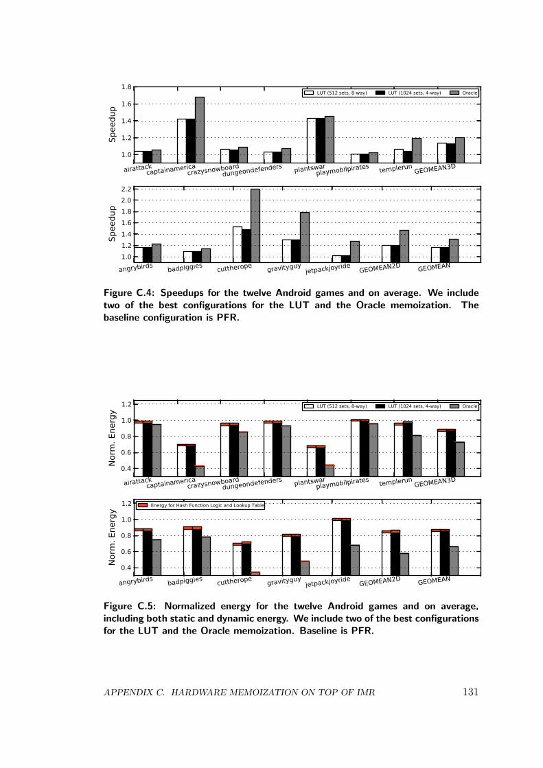
1.0
1.2
1.4
1.6
1.8
Spee
dup
airattackcaptainamerica
crazysnowboarddungeondefenders plantswar
playmobilpirates templerunGEOMEAN3D
LUT (512 sets, 8-way) LUT (1024 sets, 4-way) Oracle
1.01.21.41.61.82.02.2
Spee
dup
angrybirds badpiggies cuttherope gravityguyjetpackjoyride
GEOMEAN2D GEOMEAN
Figure C.4: Speedups for the twelve Android games and on average. We includetwo of the best configurations for the LUT and the Oracle memoization. Thebaseline configuration is PFR.
0.4
0.6
0.8
1.0
1.2
Norm
. Ene
rgy
airattackcaptainamerica
crazysnowboarddungeondefenders plantswar
playmobilpirates templerunGEOMEAN3D
LUT (512 sets, 8-way) LUT (1024 sets, 4-way) Oracle
0.4
0.6
0.8
1.0
1.2
Norm
. Ene
rgy
angrybirds badpiggies cuttherope gravityguyjetpackjoyride
GEOMEAN2D GEOMEAN
Energy for Hash Function Logic and Lookup Table
Figure C.5: Normalized energy for the twelve Android games and on average,including both static and dynamic energy. We include two of the best configurationsfor the LUT and the Oracle memoization. Baseline is PFR.
APPENDIX C. HARDWARE MEMOIZATION ON TOP OF IMR 131
Bibliography
[1] AMD Compressed ATC Texture. http://www.khronos.org/registry/
gles/extensions/AMD/AMD_compressed_ATC_texture.txt.
[2] Android Graphics. https://source.android.com/devices/graphics.
html.
[3] Android SDK. http://developer.android.com/sdk/index.html.
[4] Angry Birds has been downloaded more than a billion times. http://bgr.com/2012/05/09/angry-birds-iphone-android-billion-downloads/.
[5] Apple iPad Air. http://www.gsmarena.com/apple_ipad_air-5797.php.
[6] Apple iPhone 5S. http://www.gsmarena.com/apple_iphone_5s-5685.
php.
[7] ARB Fragment Program. http://oss.sgi.com/projects/ogl-sample/
registry/ARB/fragment_program.txt.
[8] ARM Frame Buffer Compression. http://www.arm.com/products/
multimedia/mali-technologies/arm-frame-buffer-compression.php.
[9] ARM Mali. http://www.arm.com/products/multimedia/
mali-graphics-hardware/.
[10] Blending in OpenGL. http://www.opengl.org/wiki/Blending.
[11] FlexRender. http://www.qualcomm.com/media/videos/
flexrender-rendered-useful.
[12] Gallium3D Technical Overview. http://www.freedesktop.org/wiki/
Software/gallium/.
[13] Get started with compute shaders. http://community.
arm.com/groups/arm-mali-graphics/blog/2014/04/17/
get-started-with-compute-shaders?sf25287757=1.
[14] GFXBench - Unified Graphics Benchmark based on DXBenchmark (Di-rectX) and GLBenchmark (OpenGL ES). http://gfxbench.com/result.jsp.
BIBLIOGRAPHY 132
[15] Hardware Occlusion Queries Made Useful. http://http.developer.
nvidia.com/GPUGems2/gpugems2_chapter06.html.
[16] Highlights from the Candy Crush IPO filing: 500 Million Downloadsand Counting. http://www.businessweek.com/articles/2014-02-18/
king-digitals-ipo-filing-shows-500-million-candy-crush-downloads.
[17] HTC One X. http://www.gsmarena.com/htc_one_x-4320.php.
[18] Huawei Ascend G615. http://www.gsmarena.com/huawei_ascend_
g615-5257.php.
[19] iOS Dev Center. https://developer.apple.com/devcenter/ios/index.action.
[20] The Khronos Group Inc. http://www.khronos.org/.
[21] Killing Pixels - A New Optimization for Shading on ARM Mali Gpus. http://community.arm.com/groups/arm-mali-graphics/blog/2013/08/08/
killing-pixels--a-new-optimization-for-shading-on-arm-mali-gpus.
[22] LG Nexus 5. http://www.gsmarena.com/lg_nexus_5-5705.php.
[23] The Mali GPU: An Abstract Machine, Part 3 - The Shader Core. http:
//community.arm.com/groups/arm-mali-graphics/blog/2014/03/12/
the-mali-gpu-an-abstract-machine-part-3--the-shader-core.
[24] Number of Android applications. http://www.appbrain.com/stats/
number-of-android-apps.
[25] NVIDIA SHIELD. http://shield.nvidia.com/.
[26] NVIDIA Tegra. http://www.nvidia.com/object/tegra.html.
[27] Playstation Vita. http://us.playstation.com/psvita/tech-specs/.
[28] PowerVR Series6 GPU. http://www.imgtec.com/powervr/series6.asp.
[29] QEMU. http://wiki.qemu.org/Main_Page.
[30] Qualcomm Snapdragon S4 (Krait) Performance Pre-view - 1.5 Ghz MSM8960 MDP and Adreno 225Benchmarks. http://www.anandtech.com/show/5559/
qualcomm-snapdragon-s4-krait-performance-preview-msm8960-adreno-225-benchmarks.
[31] Samsung Galaxy S3. http://www.gsmarena.com/samsung_galaxy_s_
iii_i747-4803.php.
[32] Samsung Galaxy S5. http://www.gsmarena.com/samsung_galaxy_
s5-6033.php.
[33] Samsung Galaxy Tab 3. http://www.gsmarena.com/samsung_galaxy_
tab_3_lite_7_0_3g-5975.php.
BIBLIOGRAPHY 133
[34] Sony Xperia Tablet S. http://www.gsmarena.com/sony_xperia_tablet_s-4913.php.
[35] Sony Xperia Z2. http://www.gsmarena.com/sony_xperia_z2-6144.php.
[36] Transform Feedback. https://www.opengl.org/wiki/Transform_
Feedback.
[37] Tungsten Graphics Shader Infrastructure. http://people.freedesktop.
org/~csimpson/gallium-docs/tgsi.html.
[38] Unity Game Engine. http://unity3d.com/.
[39] Unreal Engine Technology. https://www.unrealengine.com/.
[40] Using Hardware Acceleration in the Android Emulator. http:
//developer.android.com/tools/devices/emulator.html#
acceleration.
[41] Vivante Composition Processing Cores. http://www.vivantecorp.com/
index.php/en/technology/composition.html.
[42] Vivante Vega 3D Technology. http://www.vivantecorp.com/index.php/en/technology/3d.html.
[43] Ahmed K. Abousamra, Rami G. Melhem, and Alex K. Jones. Noc-awarecache design for chip multiprocessors. In Proceedings of the 19th Interna-tional Conference on Parallel Architectures and Compilation Techniques,PACT ’10, pages 565–566, New York, NY, USA, 2010. ACM.
[44] T. Akenine-Moller and J. Strom. Graphics Processing Units for Handhelds.Proc. of the IEEE, 96(5):779–789, 2008.
[45] Tomas Akenine-Moller and Bjorn Johnsson. Performance per what? Jour-nal of Computer Graphics Techniques (JCGT), 1(1):37–41, Oct 2012.
[46] Tomas Akenine-Moller, Jacob Munkberg, and Jon Hasselgren. Stochasticrasterization using time-continuous triangles. In Proceedings of the 22NdACM SIGGRAPH/EUROGRAPHICS Symposium on Graphics Hardware,GH’07, pages 7–16, 2007.
[47] Tomas Akenine-Moller and Jacob Strom. Graphics for the Masses: A Hard-ware Rasterization Architecture for Mobile Phones. ACM Transactions onGraphics, 22:801–808, 2003.
[48] Hussein Al-Zoubi, Aleksandar Milenkovic, and Milena Milenkovic. Per-formance evaluation of cache replacement policies for the spec cpu2000benchmark suite. In Proceedings of the 42Nd Annual Southeast RegionalConference, ACM-SE 42, pages 267–272, 2004.
BIBLIOGRAPHY 134
[49] Carlos Alvarez, Jesus Corbal, Esther Salamı, and Mateo Valero. On the po-tential of tolerant region reuse for multimedia applications. In Proceedingsof the 15th International Conference on Supercomputing, ICS ’01, pages218–228, 2001.
[50] Carlos Alvarez, Jesus Corbal, and Mateo Valero. Dynamic tolerance re-gion computing for multimedia. IEEE Trans. Comput., 61(5):650–665, May2012.
[51] I. Antochi. Suitability of Tile-Based Rendering for Low-Power 3D GraphicsAccelerators. PhD thesis, 2007.
[52] Iosif Antochi, Ben H. H. Juurlink, Stamatis Vassiliadis, and Petri Liuha.Memory Bandwidth Requirements of Tile-Based Rendering. In SAMOS,pages 323–332, 2004.
[53] ARM. ARM Mali-55. http://mobile.arm.com/products/multimedia/
mali-graphics-hardware/mali-55.php.
[54] ARM. ARM Mali-T678. http://www.arm.com/products/multimedia/
mali-graphics-plus-gpu-compute/mali-t678.php.
[55] ARM. Mali-400 MP: A Scalable GPU for Mobile Devices.http://www.highperformancegraphics.org/previous/www_2010/
media/Hot3D/HPG2010_Hot3D_ARM.pdf.
[56] ARM. Mali GPU Application Optimization Guide. http:
//infocenter.arm.com/help/index.jsp?topic=/com.arm.doc.
dui0555a/CHDIAHCC.html.
[57] ARM. Transaction elimination. http://www.arm.com/products/
multimedia/mali-technologies/transaction-elimination.php.
[58] Jean-Loup Baer and Tien-Fu Chen. Effective hardware-based data prefetch-ing for high-performance processors. IEEE Trans. Comput., 44(5):609–623,May 1995.
[59] A. Bakhoda, G.L. Yuan, W.W.L. Fung, H. Wong, and T.M. Aamodt. An-alyzing CUDA Workloads Using a Detailed GPU Simulator. In Proc. ofISPASS, pages 163–174, 2009.
[60] Andrew C. Beers, Maneesh Agrawala, and Navin Chaddha. Renderingfrom compressed textures. In Proceedings of the 23rd Annual Conferenceon Computer Graphics and Interactive Techniques, SIGGRAPH ’96, pages373–378, New York, NY, USA, 1996. ACM.
[61] Slo-Li Chu, Chih-Chieh Hsiao, and Chen-Yu Chen. A Dual-Mode UnifiedShader with Frame-Based Dynamic Precision Adjustment for Mobile GPUs.In IEEE/IFIP 9th International Conference on Embedded and UbiquitousComputing, EUC 2011, Melbourne, Australia, October 24-26, 2011, EUC.IEEE, 2011.
BIBLIOGRAPHY 135
[62] Slo-Li Chu, Chih-Chieh Hsiao, and Chen-Yu Chen. Program-based Dy-namic Precision Selection Framework with a Dual-mode Unified Shader forMobile GPUs. Comput. Electr. Eng., 39(7):2183–2196, October 2013.
[63] Slo-Li Chu, Chih-Chieh Hsiao, and Chiu-Cheng Hsieh. An Energy-EfficientUnified Register File for Mobile GPUs. In Embedded and Ubiquitous Com-puting (EUC), 2011 IFIP 9th International Conference on, pages 166–173,2011.
[64] Daniel Citron, Dror G. Feitelson, and Larry Rudolph. Accelerating multi-media processing by implementing memoing in multiplication and divisionunits. In ASPLOS, pages 252–261, 1998.
[65] S. Collange, M. Daumas, D. Defour, and D. Parello. Barra: A ParallelFunctional Simulator for GPGPU. In Proc. of MASCOTS, pages 351–360,2010.
[66] Daniel A. Connors, Hillery C. Hunter, Ben-Chung Cheng, and Wen-mei W.Hwu. Hardware support for dynamic activation of compiler-directed com-putation reuse. In Proceedings of the Ninth International Conference onArchitectural Support for Programming Languages and Operating Systems,ASPLOS IX, pages 222–233, 2000.
[67] R. L. Cook and K. E. Torrance. A Reflectance Model for Computer Graph-ics. ACM Trans. Graph., 1(1):7–24, January 1982.
[68] NVIDIA Corporation. NVIDIAs Next Generation CUDA Compute Ar-chitecture: Fermi. http://www.nvidia.com/content/PDF/fermi_white_
papers/NVIDIA_Fermi_Compute_Architecture_Whitepaper.pdf.
[69] Michael Cox and Pat Hanrahan. Pixel merging for object-parallel rendering:A distributed snooping algorithm. In Proceedings of the 1993 Symposiumon Parallel Rendering, PRS ’93, pages 49–56, New York, NY, USA, 1993.ACM.
[70] Neal C. Crago, Omid Azizi, Steven S. Lumetta, and Sanjay J. Patel. Hybridlatency tolerance for robust energy-efficiency on 1000-core data parallelprocessors. 2013 IEEE 19th International Symposium on High PerformanceComputer Architecture (HPCA), 0:294–305, 2013.
[71] Neal Clayton Crago and Sanjay Jeram Patel. Outrider: Efficient memorylatency tolerance with decoupled strands. In Proceedings of the 38th AnnualInternational Symposium on Computer Architecture, ISCA ’11, pages 117–128, New York, NY, USA, 2011. ACM.
[72] Jem Davies. Keynote I: Energy-efficient GPUs from mobile to supercomput-ers. In 1st annual Workshop on Parallelism in Mobile Platforms, PRISM-1,2013.
[73] Kayvon Fatahalian and Mike Houston. A Closer Look at GPUs. Commun.ACM, 51(10):50–57, October 2008.
BIBLIOGRAPHY 136
[74] Simon Fenney. Texture compression using low-frequency signal modulation.In Proceedings of the ACM SIGGRAPH/EUROGRAPHICS Conference onGraphics Hardware, HWWS ’03, pages 84–91, Aire-la-Ville, Switzerland,Switzerland, 2003. Eurographics Association.
[75] Krisztian Flautner, Nam Sung Kim, Steve Martin, David Blaauw, andTrevor Mudge. Drowsy caches: Simple techniques for reducing leakagepower. In Proceedings of the 29th Annual International Symposium onComputer Architecture, ISCA ’02, pages 148–157, Washington, DC, USA,2002. IEEE Computer Society.
[76] Richard Fromm, Stylianos Perissakis, Neal Cardwell, ChristoforosKozyrakis, Bruce McGaughy, David Patterson, Tom Anderson, and Kather-ine Yelick. The Energy Efficiency of IRAM Architectures. In Proceedings ofthe 24th Annual International Symposium on Computer Architecture, ISCA’97, pages 327–337, New York, NY, USA, 1997. ACM.
[77] John W. C. Fu, Janak H. Patel, and Bob L. Janssens. Stride directedprefetching in scalar processors. SIGMICRO Newsl., 23:102–110, December1992.
[78] Antonio Garcıa-Guirado, Ricardo Fernandez-Pascual, Alberto Ros, andJose M. Garcıa. Dapsco: Distance-aware partially shared cache organi-zation. ACM Trans. Archit. Code Optim., 8(4):25:1–25:19, January 2012.
[79] Mark Gebhart, Daniel R. Johnson, David Tarjan, Stephen W. Keckler,William J. Dally, Erik Lindholm, and Kevin Skadron. Energy-efficientMechanisms for Managing Thread Context in Throughput Processors. InProceedings of the 38th Annual International Symposium on Computer Ar-chitecture, ISCA ’11, pages 235–246, New York, NY, USA, 2011. ACM.
[80] Dan Ginsburg, Budirijanto Purnomo, Dave Shreiner, and Aaftab Munshi.OpenGL ES 3.0 Programming Guide. Addison-Wesley Professional, 2014.
[81] E. Bruce Goldstein. Sensation and Perception. Univ. of Pittsburgh, 6edition, 2002.
[82] Antonio Gonzlez, Jordi Tubella, and Carlos Molina. Trace-level reuse. InIn Proceedings of the the International Conference on Parallel Processing,1999.
[83] Ziyad S. Hakura and Anoop Gupta. The Design and Analysis of a CacheArchitecture for Texture Mapping. In Proceedings of the 24th annual inter-national symposium on Computer architecture, ISCA ’97, pages 108–120,New York, NY, USA, 1997. ACM.
[84] Marty Hall and James Mayfield. Improving the performance of ai software:Payoffs and pitfalls in using automatic memoization. In In Proceedings ofthe Sixth International Symposium on Artificial Intelligence, pages 178–184,1993.
BIBLIOGRAPHY 137
[85] Nikos Hardavellas, Michael Ferdman, Babak Falsafi, and Anastasia Ail-amaki. Reactive nuca: Near-optimal block placement and replication indistributed caches. In Proceedings of the 36th Annual International Sympo-sium on Computer Architecture, ISCA ’09, pages 184–195, New York, NY,USA, 2009. ACM.
[86] Jon Hasselgren and Tomas Akenine-Moller. Efficient Depth Buffer Com-pression. In Proceedings of the 21st ACM SIGGRAPH/EUROGRAPHICSsymposium on Graphics hardware, GH ’06, pages 103–110, New York, NY,USA, 2006. ACM.
[87] Jon Hasselgren and Tomas Akenine-Moller. An Efficient Multi-View Raster-ization Architecture. In Proceedings of the 17th Eurographics conference onRendering Techniques, EGSR’06, pages 61–72, Aire-la-Ville, Switzerland,Switzerland, 2006. Eurographics Association.
[88] Chih-Chieh Hsiao, Slo-Li Chu, and Chen-Yu Chen. Energy-aware HybridPrecision Selection Framework for Mobile GPUs. Computers & Graphics,37(5):431–444, 2013.
[89] Chih-Chieh Hsiao, Slo-Li Chu, and Chiu-Cheng Hsieh. An Adaptive ThreadScheduling Mechanism With Low-Power Register File for Mobile GPUs.IEEE Transactions on Multimedia, 16(1):60–67, 2014.
[90] Chih-Chieh Hsiao, Chiu-Cheng Hsieh, and Slo-Li Chu. An energy-efficientdemand-driven register file for mobile gpus. Journal of Circuits, Systems,and Computers, 23(2), 2014.
[91] Jian Huang and David J. Lilja. Exploiting basic block value locality withblock reuse. In HPCA, pages 106–114, 1999.
[92] IDC. Android and iOS Continue to Dominate the Worldwide SmartphoneMarket. http://www.idc.com/getdoc.jsp?containerId=prUS24676414.
[93] Homan Igehy, Matthew Eldridge, and Kekoa Proudfoot. Prefetching in atexture cache architecture. In SIGGRAPH / Eurographics Workshop onGraphics Hardware, pages 133–142, 1998.
[94] The Khronos Group Inc. OpenGL ES. http://www.khronos.org/
opengles/.
[95] The Khronos Group Inc. OpenGL ES Common Profile Specification Version2.0.25. http://www.khronos.org/registry/gles/specs/2.0/es_full_
spec_2.0.25.pdf.
[96] The Khronos Group Inc. OpenGL ES Common/Common-Lite ProfileSpecification Version 1.1.12. http://www.khronos.org/registry/gles/
specs/1.1/es_full_spec_1.1.12.pdf.
[97] The Khronos Group Inc. OpenGL ES Version 3.0.3. http://www.khronos.org/registry/gles/specs/3.0/es_spec_3.0.3.pdf.
BIBLIOGRAPHY 138
[98] The Khronos Group Inc. OpenGL ES Version 3.1. http://www.khronos.org/registry/gles/specs/3.1/es_spec_3.1.pdf.
[99] The Khronos Group Inc. WebGL Specification 1.0. https://www.khronos.org/registry/webgl/specs/1.0/.
[100] Doug Joseph and Dirk Grunwald. Prefetching using markov predictors. InIn Proceedings of the 24th Annual International Symposium on ComputerArchitecture, pages 252–263, 1997.
[101] B. Juurlink, I. Antochi, D. Crisu, S. Cotofana, and S. Vassiliadis. GRAAL:A Framework for Low-Power 3D Graphics Accelerators. IEEE ComputerGraphics and Applications, 28(4):63–73, 2008.
[102] Gokul B. Kandiraju and Anand Sivasubramaniam. Going the distancefor tlb prefetching: an application-driven study. In Proceedings of the 29thannual international symposium on Computer architecture, ISCA ’02, pages195–206, Washington, DC, USA, 2002. IEEE Computer Society.
[103] Stefanos Kaxiras, Polychronis Xekalakis, and Georgios Keramidas. InKaushik Roy and Vivek Tiwari, editors, ISLPED, pages 54–59. ACM.
[104] Georgios Keramidas, Pavlos Petoumenos, and Stefanos Kaxiras. Cachereplacement based on reuse-distance prediction. In Proceedings of the 25thInternational Conference on Computer Design, ICCD, pages 245–250, 2007.
[105] G. Knittel, A. Schilling, A. Kugler, and W. Strasser. Hardware for superiortexture performance. In Proceedings of the Tenth Eurographics Conferenceon Graphics Hardware, EGGH’95, pages 33–40, Aire-la-Ville, Switzerland,Switzerland, 1995. Eurographics Association.
[106] Jaekyu Lee, Nagesh B. Lakshminarayana, Hyesoon Kim, and RichardVuduc. Many-thread aware prefetching mechanisms for gpgpu applica-tions. IEEE/ACM International Symposium on Microarchitecture, 0:213–224, 2010.
[107] Sheng Li, Jung Ho Ahn, Richard D. Strong, Jay B. Brockman, Dean M.Tullsen, and Norman P. Jouppi. McPAT: An Integrated Power, Area, andTiming Modeling Framework for Multicore and Manycore Architectures.In Proc. of MICRO, pages 469–480, 2009.
[108] Gabor Liktor and Carsten Dachsbacher. Decoupled deferred shading forhardware rasterization. In Proceedings of the ACM SIGGRAPH Symposiumon Interactive 3D Graphics and Games, I3D’12, pages 143–150, 2012.
[109] D Mccabe and J Brothers. DirectX 6 Texture Map Compression. GameDeveloper Magazine 5, pages 42–46, August 1998.
[110] Paul McNamee and Marty Hall. Developing a tool for memoizing functionsin c++. SIGPLAN Not., 33(8):17–22, August 1998.
BIBLIOGRAPHY 139
[111] Bren Mochocki, Kanishka Lahiri, and Srihari Cadambi. Power Analysisof Mobile 3D Graphics. In Proceedings of the Conference on Design, Au-tomation and Test in Europe: Proceedings, DATE ’06, pages 502–507, 3001Leuven, Belgium, Belgium, 2006. European Design and Automation Asso-ciation.
[112] Jordi Roca Monfort and Mark Grossman. Scaling of 3D Game Engine Work-loads on Modern multi-GPU Systems. In Proceedings of the Conference onHigh Performance Graphics 2009, HPG ’09, pages 37–46, New York, NY,USA, 2009. ACM.
[113] Victor Moya, Carlos Gonzalez, Jordi Roca, Agustin Fernandez, and RogerEspasa. ATTILA: A Cycle-level Execution-Driven Simulator for ModernGPU Architectures. In Proc. of ISPASS, pages 231–241, 2006.
[114] Kyle J. Nesbit and James E. Smith. Data cache prefetching using a globalhistory buffer. IEEE Micro, 25(1):90–97, 2005.
[115] NVIDIA. Bringing High-End Graphics to Handheld Devices.http://www.nvidia.com/content/PDF/tegra_white_papers/
Bringing_High-End_Graphics_to_Handheld_Devices.pdf.
[116] NVIDIA. CUDA C Programming Guide. http://docs.nvidia.com/cuda/cuda-c-programming-guide/.
[117] NVIDIA. NVIDIA Tegra 4 Family GPU Architecture. http://www.
nvidia.com/docs/IO//116757/Tegra_4_GPU_Whitepaper_FINALv2.pdf.
[118] NVIDIA. SLI Best Practices. http://developer.download.nvidia.com/whitepapers/2011/SLI_Best_Practices_2011_Feb.pdf.
[119] J. Nystad, A. Lassen, A. Pomianowski, S. Ellis, and T. Olson. AdaptiveScalable Texture Compression. In Proceedings of the Fourth ACM SIG-GRAPH / Eurographics conference on High-Performance Graphics, EGGH-HPG’12, pages 105–114. Eurographics Association, 2012.
[120] Tom Olson. How low can you go? Building low-power,low-bandwidth ARM Mali GPUs. http://community.
arm.com/groups/arm-mali-graphics/blog/2012/08/17/
how-low-can-you-go-building-low-power-low-bandwidth-arm-mali-gpus.
[121] Tom Olson. Triangles Per Second: Performance Met-ric or Chocolate Teapot? http://community.
arm.com/groups/arm-mali-graphics/blog/2011/02/22/
triangles-per-second-performance-metric-or-chocolate-teapot.
[122] Joan-Manuel Parcerisa and Antonio Gonzalez. Improving latency toleranceof multithreading through decoupling. IEEE Trans. Comput., 50(10):1084–1094, October 2001.
BIBLIOGRAPHY 140
[123] Anton Pereberin. Hierarchical Approach for Texture Compression. In Pro-ceedings of GraphiCon ’99, pages 195–199, 1999.
[124] Jeff Pool, Anselmo Lastra, and Montek Singh. A Per-Unit Breakdown ofthe Energy Consumption in a Graphics Processing Unit. http://www.cs.unc.edu/~jpool/research/ICCD2010Extension/index.html.
[125] Jeff Pool, Anselmo Lastra, and Montek Singh. An Energy Model for Graph-ics Processing Units. In ICCD, pages 409–416. IEEE, 2010.
[126] Kari Pulli, Tomi Aarnio, Kimmo Roimela, and Jani Vaarala. Design-ing Graphics Programming Interfaces for Mobile Devices. IEEE Comput.Graph. Appl., 25(6):66–75, November 2005.
[127] Qualcomm. Composition with Snapdragon. https://developer.
qualcomm.com/sites/default/files/composition-with-snapdragon.
pdf.
[128] Jim Rasmusson, Jon Hasselgren, and Tomas Akenine-Moller. Exact andError-Bounded Approximate Color Buffer Compression and Decompres-sion. In Proceedings of the 22nd ACM SIGGRAPH/EUROGRAPHICSsymposium on Graphics hardware, GH ’07, pages 41–48, Aire-la-Ville,Switzerland, Switzerland, 2007. Eurographics Association.
[129] Vijay Janapa Reddi. Architecting for the Mobile Web: Where We’ve Been,Where We’re Heading, and What We Need to Address. In Keynote of the2nd annual workshop on parallelism in mobile platforms, PRISM-2, 2014.
[130] W. T. Reeves. Particle Systems: A Technique for Modeling a Class ofFuzzy Objects. ACM Trans. Graph., 2(2):91–108, April 1983.
[131] Matthew J. P. Regan, Gavin S. P. Miller, Steven M. Rubin, and ChrisKogelnik. A Real-Time Low-Latency Hardware Light-Field Renderer. InProceedings of the 26th annual conference on Computer graphics and inter-active techniques, SIGGRAPH ’99, pages 287–290, New York, NY, USA,1999. ACM Press/Addison-Wesley Publishing Co.
[132] Hugo Rito and Joao Cachopo. Memoization of methods using softwaretransactional memory to track internal state dependencies. In Proceedingsof the 8th International Conference on the Principles and Practice of Pro-gramming in Java, PPPJ’10, pages 89–98, 2010.
[133] Paul Rosenfeld, Elliott Cooper-Balis, and Bruce Jacob. Dramsim2: A cycleaccurate memory system simulator. IEEE Comput. Archit. Lett., 10(1):16–19, January 2011.
[134] S. Subramanya Sastry, Rastislav Bodik, and James E. Smith. Charac-terizing coarse-grained reuse of computation. In 3rd ACM Workshop onFeedback Directed and Dynamic Optimization, pages 16–18, 2000.
BIBLIOGRAPHY 141
[135] Ankit Sethia, Ganesh Dasika, Mehrzad Samadi, and Scott Mahlke. Apogee:Adaptive prefetching on gpus for energy efficiency. In Proceedings of the22Nd International Conference on Parallel Architectures and CompilationTechniques, PACT ’13, pages 73–82, Piscataway, NJ, USA, 2013. IEEEPress.
[136] J. W. Sheaffer, D. Luebke, and K. Skadron. A Flexible Simulation Frame-work for Graphics Architectures. In Proc. of the EUROGRAPHICS Conf.on Graphics Hardware, pages 85–94, 2004.
[137] Alex Shye, Benjamin Scholbrock, and Gokhan Memik. Into the Wild:Studying Real User Activity Patterns to Guide Power Optimizations forMobile Architectures. In Proceedings of the 42Nd Annual IEEE/ACM In-ternational Symposium on Microarchitecture, MICRO 42, pages 168–178,New York, NY, USA, 2009. ACM.
[138] James E. Smith. Decoupled Access/Execute Computer Architectures. InProceedings of the 9th Annual Symposium on Computer Architecture, ISCA’82, pages 112–119, Los Alamitos, CA, USA, 1982. IEEE Computer SocietyPress.
[139] Avinash Sodani and Gurindar S. Sohi. Dynamic instruction reuse. InProceedings of the 24th Annual International Symposium on Computer Ar-chitecture, ISCA ’97, pages 194–205, 1997.
[140] Jacob Strom and Tomas Akenine-Moller. iPACKMAN: High-Quality, Low-Complexity Texture Compression for Mobile Phones. In Proceedings of theACM SIGGRAPH/EUROGRAPHICS conference on Graphics hardware,HWWS ’05, pages 63–70, New York, NY, USA, 2005. ACM.
[141] Deependra Talla and Lizy K. John. Mediabreeze: A decoupled architecturefor accelerating multimedia applications. SIGARCH Comput. Archit. News,29(5):62–67, December 2001.
[142] Deependra Talla, Lizy Kurian John, and Doug Burger. Bottlenecks in mul-timedia processing with simd style extensions and architectural enhance-ments. IEEE Trans. Computers, 52(8):1015–1031, 2003.
[143] David Tarjan and Kevin Skadron. The sharing tracker: Using ideas fromcache coherence hardware to reduce off-chip memory traffic with non-coherent caches. In Proceedings of the 2010 ACM/IEEE International Con-ference for High Performance Computing, Networking, Storage and Anal-ysis, SC ’10, pages 1–10, Washington, DC, USA, 2010. IEEE ComputerSociety.
[144] Hung-Wei Tseng and Dean M. Tullsen. Data-triggered threads: Eliminatingredundant computation. In Proceedings of the 17th International Sympo-sium on High Performance Computer Architecture, HPCA, pages 181–192,2011.
BIBLIOGRAPHY 142
[145] Tomoaki Tsumura, Ikuma Suzuki, Yasuki Ikeuchi, Hiroshi Matsuo, HiroshiNakashima, and Yasuhiko Nakashima. Design and evaluation of an auto-memoization processor. In Parallel and Distributed Computing and Net-works, pages 230–235, 2007.
[146] Rafael Ubal, Julio Sahuquillo, Salvador Petit, and Pedro Lopez. Multi2Sim:A Simulation Framework for CPU-GPU Computing . In Proc. of the 19thInternational Symposium on Computer Architecture and High PerformanceComputing, Oct. 2007.
[147] Po-Han Wang, Yen-Ming Chen, Chia-Lin Yang, and Yu-Jung Cheng. Apredictive shutdown technique for gpu shader processors. Computer Archi-tecture Letters, pages 9–12, 2009.
[148] Po-Han Wang, Chia-Lin Yang, Yen-Ming Chen, and Yu-Jung Cheng. Powergating strategies on gpus. ACM Trans. Archit. Code Optim., 8(3):13:1–13:25, October 2011.
[149] Zhou Wang, A.C. Bovik, H.R. Sheikh, and E.P. Simoncelli. Image QualityAssessment: from Error Visibility to Structural Similarity. IEEE Transac-tions on Image Processing, 13(4):600–612, 2004.
[150] Wikipedia. ARM Mali. http://en.wikipedia.org/wiki/Mali_%28GPU%
29.
[151] Wikipedia. Ericsson Texture Compression. http://en.wikipedia.org/
wiki/Ericsson_Texture_Compression.
[152] Wikipedia. Fillrate. http://en.wikipedia.org/wiki/Fillrate.
[153] Wikipedia. Mean Squared Error. http://en.wikipedia.org/wiki/Mean_squared_error.
[154] Wikipedia. Micro Stuttering. http://en.wikipedia.org/wiki/Micro_
stuttering.
[155] Wikipedia. Multiple Render Targets. http://en.wikipedia.org/wiki/
Multiple_Render_Targets.
[156] Wikipedia. Nintendo 3DS. http://en.wikipedia.org/wiki/Nintendo_
3DS.
[157] Wikipedia. OpenGL ES. http://en.wikipedia.org/wiki/OpenGL_ES.
[158] Wikipedia. Peak Signal-to-Noise Ratio. http://en.wikipedia.org/wiki/Peak_signal-to-noise_ratio.
[159] Wikipedia. Performance per watt. http://en.wikipedia.org/wiki/
Performance_per_watt.
[160] Wikipedia. PICA-200. http://en.wikipedia.org/wiki/PICA200.
BIBLIOGRAPHY 143
[161] Wikipedia. PowerVR. http://en.wikipedia.org/wiki/PowerVR.
[162] Wikipedia. Qualcomm Adreno. http://en.wikipedia.org/wiki/Adreno.
[163] Wikipedia. Qualcomm snapdragon. http://en.wikipedia.org/wiki/
Snapdragon_%28system_on_chip%29.
[164] Wikipedia. Samsung Exynos. http://en.wikipedia.org/wiki/Exynos.
[165] Wikipedia. Tiled rendering. http://en.wikipedia.org/wiki/Tiled_
rendering.
[166] Lance Williams. Casting Curved Shadows on Curved Surfaces. In Proceed-ings of the 5th Annual Conference on Computer Graphics and InteractiveTechniques, SIGGRAPH ’78, pages 270–274, New York, NY, USA, 1978.ACM.
[167] Jeong-Ho Woo, Min-Wuk Lee, Hye-Jung Kim, R. Woo, and Hoi-Jun Yoo. A155-mw 50-m vertices/s graphics processor with fixed-point programmablevertex shader for mobile applications. IEEE Journal of Solid-State Circuits,41(5):1081–1091, May 2006.
[168] Haiying Xu, Christopher J. F. Pickett, and Clark Verbrugge. Dynamic pu-rity analysis for java programs. In Proceedings of the 7th ACM SIGPLAN-SIGSOFT Workshop on Program Analysis for Software Tools and Engi-neering, PASTE ’07, pages 75–82, 2007.
[169] Wing-kei S. Yu, Ruirui Huang, Sarah Q. Xu, Sung-En Wang, Edwin Kan,and G. Edward Suh. Sram-dram hybrid memory with applications to ef-ficient register files in fine-grained multi-threading. In Proceedings of the38th Annual International Symposium on Computer Architecture, ISCA ’11,pages 247–258, New York, NY, USA, 2011. ACM.
[170] GPUWattch. http://www.gpgpu-sim.org/gpuwattch/.
[171] Microsoft Direct3D. http://en.wikipedia.org/wiki/Microsoft_
Direct3D.
[172] OpenCL. http://www.khronos.org/opencl/.
[173] Carlos lvarez, Jess Corbal, and Mateo Valero. Fuzzy memoization forfloating-point multimedia applications. IEEE Transactions on Computers,54(7):922–927, 2005.
BIBLIOGRAPHY 144