Embed Size (px)
Citation preview

Transforming The fuTure
OTN | OTR | OTFenergY generaTion/DisTriBuTion anD inDusTriaL Transformers

2
SEA IQTrafotec Technology
OTN | OTR | OTF High Quality Standards
managemenT sYsTem
The Quality of our products is achieved by processes that are continuously refined, combining experience in the electromechanical sector since 1959 with the most modern technologies, and approved in accordance with the most important Standards concerning the Quality (EN ISO 9001) and Environmental (EN ISO 14001) Management System. Moreover, OTN/OTR/OTF transformers comply with the IEC and DIN standards, with the possibility of correspondence with other International Standards or Customer Specifications (BS, ANSI, IEE, GOST, etc...).
ProDucTion QuaLiTY
The high reliability of the products results from a continuous perseverance in achieving high quality standards during all “supply chain” phases. Especially during the production cycles there is a strict compliance with the implemented control parameters, which assure both the suitability of the assembled components and the performance of the finished product, all this even through tests carried out at our internal laboratories equipped with the most modern instruments available for type-testing or special testing, if the customer requests it.
environmenTaL asPecTs
The constant research aimed at improving efficiency merges with the commitment to minimize environmental impacts. This is another essential issue on which SEA focuses its corporate policy. All this has an impact on both the construction process and the realization proposals for our OTN/OTR/OT transformers. The use of a transformer, as we all know, can produce, in case of failure, severe environmental impacts, such as, for example, various oil leaks or fire. Right with a view to reducing these serious risks, SEA focused on the most effective security systems assembled on the transformers themselves and on the type of insulating liquids used for filling them, which can be also biodegradable, upon request.
sea has been designing and manufacturing liquid immersed, cast resinand air insulated transformers, positioning itself amongthe industry leaders since 1959
iQTrafoTec®Innovative construction solutions, modern and technologically advanced processes, detailed checks throughout the entire design and construction chain asssure the total quality of the product.SEA has established procedures to assure the TOTAL QUALITY of its products availing itself on its own know-how and adapting it to innovative manufacturing processes and strict control procedures. This type of technology has been identified by SEA with the name IQTRAFOTEC®, a brand guaranteeing a continual commitment to improve the product and its manufacture, considering 4 main areas such as:
Safety of the working environment
Quality of the product
Saving of materials and reduction of waste
Lowest environmental impact during manufacture, maintenance and after use.

3
OTN | OTR | OTF Energy generation/distribution and industrial transformers
oTn Transformers PerfecT for The energY inTegraTionin The neTWorK
Among the phases preceding the process that leads to the use of energy by the final consumer, there are production, transmission, distribution or conversion. Usually the energy in the power generation stations - both conventional and hydroelectric, wind, solar, etc. - is produced at MV level; in order to be transferred and distributed to end-users, voltage must be increased to levels of hundreds of kV. In order to make this increase possible, it is necessary to provide for Step-up or voltage increasing transformers in the power generation stations. Therefore, a power transformer is used in all those applications where it is necessary to connect systems for the generation, transmission, distribution and use of electrical energy, working at different voltages, with the purpose of transferring large quantities of active and reactive energy among the above mentioned systems.The type of transformers of the series OTN, OTR and OTF, thanks to the new production area and the new test room, are machines with powers largely covering 245 kV class.
sea provides the right transformer for each specific need,ensuring reliability and high level performance
oTr Transformers suiTaBLe for ac/Dc converTion
They reach rated powers up to 60 MVA and voltages up to 245 kV, with double LV secondary winding, variable flow adjustment, or booster or inlet self-transformer.There is also the possibility to manufacture transformers with fractional phase shift, interphase reactor, etc. Rectifying transformers are usually connected to the end of the rectifier input and lower medium voltage to the suitable value for allowing connection to the same.They can be used for various applications that can range from traction to industrial applications such as, for example, electrolysis.The rated power of these transformers can range from a few MVA for trams to ten for subways. Unlike the public sector, where the transformers are three-phase and also with double secondary winding (used as a filter for harmonics), the transformers for electric traction work with a single phase and reduce high voltage to the line voltage.All transformers used can have cooling O(K)NAN / O(K)NAF / O(K)FAF / O(K)FWF / O(K)DAF, etc.
oTf sPecific Transformers for meTaLLurgicaL anD iron inDusTrY
They have powers up to 100 kA, variable flow adjustment, or with booster or self-transformer and tube or copper plate LV outputs. The main factors that must be taken into consideration in the design of transformers for furnaces are the high currents required for the melting process and the high amplitude in the range of secondary voltages, usually adjusted via an on-load tap-changer (OLTC) either directly on the high voltage winding or through an intermediate transformer positioned inside the same casing. These transformers are exposed to cyclic loads, they must withstand high electrical, mechanical and thermal stresses, as well as frequent over-currents and over-voltages, which are caused by internal short circuits in the furnace or by the tripping of the high-voltage circuit breakers. For the process industry, interruptions correspond to a loss of productivity.SEA is able to produce both single-phase and three-phase transformers for AC arc furnaces (Electric Arc Furnace), ladle furnaces, reduction furnaces (metallurgical industry) or for special applications, as well as for DC furnaces usually installed in combination with a rectifier.

4
OTN | OTR | OTF Technology
The magneTic core
Low vibrations, low losses, a beating heart with high perfomance
The continuous research of the best materials is focused on efficiency increase, as well as on reducing vibrations and, consequently, the noise level of the transformers during their use. To achieve these objectives, the core consists of magnetic metal sheet plates with oriented grain, high-permeability and low specific losses, separated from each other by an inorganic insulating means.In particular, the cut and assembly of the core are made in such a way as to create junctions according to the “STEP-LAP” way to reduce noise, as well as no-load losses and current. The magnetic pack is pressed by bent sheet metal profiles and suitable connections with or without through hull bolts when it is necessary to further reduce losses and the localized heating of the core. The overall result is a high dimensional accuracy, low loss factor values and an excellent space factor. Moreover, SEA is also able to propose solutions with amorphous sheet metal at very low no-load losses. When the size requires it, axial channels are created within the core in order to obtain a uniform temperature field.
The Design
from concept to realization
Years of experience developed into strict calculation procedures, modern design and verification programs are the basis of the technology that allows the engineers of SEA to face successfully any technological development and the most complicated design solutions requested by our customers. SEA avails itself of technologies, machinery and equipment for realizing all possible technical and construction solutions involving the transformers of the OTN, OTR and OTF series. This versatility allows optimizing the thermal sizing, insulation and resistance to overloads or heavy usage cycles for maximum application reliability and flexibility required by customers or by the design firms.
The sWiTching
The need to adapting to the network conditions
In power and special transformers, the choice of the type of adjustment and, therefore, of the corresponding windings must be made with extreme expertise and care because the adjustment has a strong impact on the main final characteristics of the transformer. In particular:
Distribution of dielectric stresses
Losses and hating
Behavior in case of short circuitFor special applications, typically dedicated to furnaces or AC/DC, converters, adjustment can be done through an additional transformer (or a self-transformer), in the same casing.
nLTc Tap changer
This type of tap-changer cannot operate when the transformer is energized. This is the most simple and economical execution and it can be of the following types:
Manual with control located on the transformer cover or on the case wall at eye level With motorized control operable even remotely Without power but under voltage, with motorized control
(special low voltage execution that has to be analyzed from time to time with our Technical Department)
oLTc Tap changer
This is the most complete version; it allows adjusting the rated power supply voltage of the transformer to the actual mains voltage within a pre-set adjustment range, without causing noises to the load. It is always supplied equipped with motor control to be operated from the control room, either manually or, more and more often, automatically by means of suitable regulators. Currently there are types of on load tap changers with oil technology or vacuum technology, which greatly reduces maintenance intervals (about 300.000 manouvres).
5
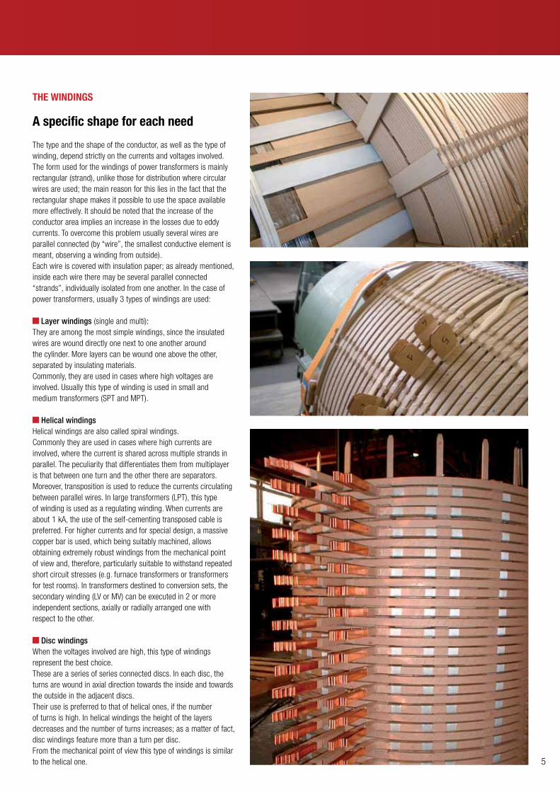
The WinDings
a specific shape for each need
The type and the shape of the conductor, as well as the type of winding, depend strictly on the currents and voltages involved.The form used for the windings of power transformers is mainly rectangular (strand), unlike those for distribution where circular wires are used; the main reason for this lies in the fact that the rectangular shape makes it possible to use the space available more effectively. It should be noted that the increase of the conductor area implies an increase in the losses due to eddy currents. To overcome this problem usually several wires are parallel connected (by “wire”, the smallest conductive element is meant, observing a winding from outside).Each wire is covered with insulation paper; as already mentioned, inside each wire there may be several parallel connected “strands”, individually isolated from one another. In the case of power transformers, usually 3 types of windings are used:
Layer windings (single and multi): They are among the most simple windings, since the insulated wires are wound directly one next to one another around the cylinder. More layers can be wound one above the other, separated by insulating materials. Commonly, they are used in cases where high voltages are involved. Usually this type of winding is used in small and medium transformers (SPT and MPT).
Helical windingsHelical windings are also called spiral windings.Commonly they are used in cases where high currents are involved, where the current is shared across multiple strands in parallel. The peculiarity that differentiates them from multiplayer is that between one turn and the other there are separators. Moreover, transposition is used to reduce the currents circulating between parallel wires. In large transformers (LPT), this type of winding is used as a regulating winding. When currents are about 1 kA, the use of the self-cementing transposed cable is preferred. For higher currents and for special design, a massive copper bar is used, which being suitably machined, allows obtaining extremely robust windings from the mechanical point of view and, therefore, particularly suitable to withstand repeated short circuit stresses (e.g. furnace transformers or transformers for test rooms). In transformers destined to conversion sets, the secondary winding (LV or MV) can be executed in 2 or more independent sections, axially or radially arranged one with respect to the other.
Disc windingsWhen the voltages involved are high, this type of windings represent the best choice.These are a series of series connected discs. In each disc, the turns are wound in axial direction towards the inside and towards the outside in the adjacent discs.Their use is preferred to that of helical ones, if the number of turns is high. In helical windings the height of the layers decreases and the number of turns increases; as a matter of fact, disc windings feature more than a turn per disc.From the mechanical point of view this type of windings is similar to the helical one.

6
OTN | OTR | OTF Technology
TanK-cover-cooLing
an high dissipating power
The cooling system plays an important, if not decisive, function for a long life of the transformer.It is the means to remove the heat produced by the windings.There are different ways to perform this delicate task; they depend mainly on factors such as the positioning of the transformer, the site and size of the transformer itself.Both mineral and silicone or biodegradable insulating liquids (MIDEL) can be cooled with methods O(K)NAN /O(K)NAF / O(K)FAF / O(K)FWF / O(K)DAF, etc.
The assemBLing of The acTive ParT
The whole is coming into groove
The insulating materials are subject to significant dimensional variations due to tolerances and the amount of humidity present in their fibers. A long experience and great care in the assembly of the active part are the secrets to guarantee our product reliability and robustness against the inevitable dielectric and electrodynamic stresses to which it will be subject during its life. The windings carefully pressed and dried in autoclave are keyed on the respective columns of the core; then, the yoke is assembled, the cover is fixed, the electrical connections are made and a new cycle of thermal treatments is performed. Before the positioning within the tank, all transformers are checked to verify the correctness of the connections, of the turn ratio and of the vectorial group. In particular cases or when requested by the customer, we can perform additional checks and measurements on the complete active part, for example measurements with recurring low voltage pulses and the measurement of the insulation system loss factor.After a careful drying cycle (with verification of the residual humidity) and a final check of the tightening torques, the complete active part is inserted inside the case as quickly as possible so as to prevent the subsequent attack by the external humidity and then vacuum filling with oil is carried out. After filling, the transformer is completed with the forecast accessories and tested as required by the reference regulations.

7
Box-TerminaLs
one customization for each installation requirement
The INDOOR and OUTDOOR maximum installation flexibility - from the offshore, up to the lowest temperatures or desert environments - is available with a full range of solutions for protecting the terminals from oil-oil to oil-SF6 till the segregated phases.
The protection degrees can be studied with customized solutions to meet any need that may arise.
TesTing room
Quality beyond the test
SEA has 3 modern testing rooms as well as of special equipment for performing routine, type and special tests according to the regulations or as required in the specifications of the customers. Moreover, SEA has a large archive of type tests and special tests (short circuit, thermal tests, behavior at very low temperatures) performed on many transformers delivered to customers all around the world.
our TargeTs
Performance anD overLoaDEfficiency studied to optimize the system.
siLenceOften these transformers are installed close totowns.
eco + PoWerSpecifically designed to meet the new requirements in the renewable energy production.
economY During the operations, purchasing and maintenance.
comPacTnessDesigned for very low dimensions in width.
resisTanceVery robust and treated to withstand to extreme conditions.

8
OTN | OTR | OTF Accessories
soluzioni studiate per coprire tutte le esigenze produttive sia a livello di realizzazione che di installazione ricordando che, l’obiettivo dei costruttori di trasformatori ed una precisa esigenza degli utilizzatori finali, è prevedere le eventuali anomalie e limitare le possibili conseguenze in caso di guasti del trasformatore stesso:
More than 20 types of accessories for the safety of the transformer
Several types of bushings (made of porcelain, epoxy resin, silicone rubber and condenser bushings...)
Various types of protections for the achievement of the desired IP degree
Various types of off-load and on-load tap changers in order to meet the customer’s various needs
The possibility of a complete range of products suitable for the corrosiveness C5 corrosiveness class in offshore environments
Now we list the most commonly used accessories identified according to their function, depending on their use or in the conservator or hermetic transformer type.
oil Temperature indicator / Winding Temperature indicator
This is a cost-effective and reliable device for the local indication of oil temperature in the higher layers or of the of the windings temperature.There is the possibility of setting two levels, one for the alarm and one for the disconnection, so as to protect the transformer in case abnormal temperature levels are detected.
Buchholz relay
It is a device, interposed between conservator and cover the connecting tube, which intercepts and “collect” any gas bubbles coming from the inner side of the transformer, which indicate a localized overheating due to a fault; when the value defined by the Standard CENELEC EN 50216-2 is reached, it allows signaling the alarm through the lowering of the upper floating element. Instead, the tripping of the transformer is possible in two cases:
Through the continuous gas formation after the alarm signal, through the lowering of the lower float the disconnection occurs, letting the tripping switch trip (the increasing gas further lowers the oil level)
Through the release of oil due to leaks from the transformer case: this event causes an increase in the oil speed from the conservator to the cover and when this limit is exceeded, the tripping switch trips
Shortly, it will be possible to have this device, combining electronics to mechanics, thus obtaining an “instantaneous” control of the internal state of the transformer both in case of abnormal gas formation and in case of oil leak.There will be an output signal that will be both analog (4-20 mA) and digital (RS485 Modbus Protocol).
shutter valve
In case happen big leaks of insulating liquid or serious injuries or fires, there is the possibility to block the leakage avoiding the environmental damages and a considerable economic loss.This can be done by interposing such device between Buchholz relay and conservator, that, upon reaching a predetermined flow, blocks the escape of insulating liquid. Both an alarm and tripping signal can be set in case the valve stop the flow.
solutions studied to cover all the production requirements in terms of both construction and installation, bearing in mind that the objective of the transformer manufacturers and a precise need of end users is to anticipate any faults and limit the possible consequences in case of failure of the transformer itself:

9
standard air breather
Air dryers are used in liquid immersed transformers and they have the function of absorbing humidity air that is necessarily sucked by the conservator during the thermal contraction of the liquid itself easing its dielectric capacitance. There is a wide range of models in relation to the amount of liquid present in the transformer. For assuring its proper operation, it must be inspected periodically as the salts contained within the same pass from the humidity-free condition (orange) to a saturated stated (green), according to the environmental stress.
self dehidrating air breather
Using such device there is the possibility to rigenerate the salt that is contained inside the tank at the beginning conditions without providing its replacement when it becames satured of moisture.It is a special type of salt that can withstand several rigeneration cycles without compromising its functionality. Some achievable targets by use of such device are:
Less environmental impact
Reduction of maintenance costs
Greater control of the drying function and, consequently, greater safety of the transformer itself. The output signal can be either analog (4 ÷20 mA) or digital (RS485 Modbus Protocol)
standard oil level indicator
The oil level indicators with magnetic joint are normally used in the transformers conservators, with the aim to give a visual signal of the contained insulating liquid. They have the switches to signal the alarm in case the liquid reaches the minimum and/or maximumn level. The oil level indicators dials can have the dimensions of 140, 220 and 340 mm with axial or radial movement of the floating rod.The axial type is very often used in case of transformers with nytrogen cushion.
electronic oil level indicator
In case one wishes to have an electronic signal in addition to the mechanical one, it is possible to use this tool for the remote control of the oil level within the conservator.This output signal may be both analog (4 ÷20 mA) and digital (RS485 Modbus Protocol).The movement of the floating element can be radial or axial, depending on the position in which the indicator has to be positioned on the conservator. The axial type may be provided with a rolling float when the conservator is equipped with “rubber cells”.

10
Pressure relief device
A sudden and violent internal short circuit in the transformers in insulating liquid produces a large volume of gas which, if not promptly evacuated, may result in the explosion of the transformer itself. There is the possibility of using a simple pressure relief device or a relief device equipped with protection and tripping signal when the pressure is affected by these instantaneous and uncontrolled increases with consequent hazards for both safety and the environment.They can be equipped with a simple protection or with a conveyor in case one wishes to collect and convey the spilled oil.The switch allows emitting an electrical signal,if the pressure relief device opens.The application of one or more pressure relief devices and their section must be proportional to the volume of oil contained in the transformer.
Shortly, it will be possible to have this tool, combining electronics to mechanics, thus obtaining an “instantaneous” control of the internal state of the transformer in case of inner pressure variation.There will be an output signal that will be both analog (4 ÷20 mA) and digital (RS485 Modbus Protocol).
composite bushings
To increase the general safety level in a transformer, it is possible to use bushings made of composite material instead of using those with traditional porcelain that can, in the event of impact, break causing oil leakages and contaminating the surroundings. This reduces also the risk of fire since the air part of the conductor (copper or aluminum) consists of a first epoxy resin coating, which is then externally coated with silicone rubber.They assure the control of partial discharges and the ability to be assembled even horizontally.They are also interchangeable with porcelain bushings in compliance to the EN 50180 standard and are suitable for use according to the C5 corrosiveness class with reference to ISO 12944. It shall be underlined that these bushings are not equipped with condenser but signal only the presence or not of the voltage passing inside them via a capacitive socket.
condenser bushings
These are insulators suitable for voltages of 25 kV up to 52 kV or greater, used in case one wishes to introduce an active control of voltage distribution between the high voltage central wire and the external grounding flange.
To have an insTanT conTroL on aLL essenTiaL ParameTers of a Transformer, sea can ProviDe ParT of The accessories WiTh an anaLog ouTPuT 4÷20 ma or a rs485 DigiTaL ouTPuT moDBus ProTocoL
OTN | OTR | OTF Accessories

11
The TransPorT anD The siTe assemBLing
sea can deliver the transformer everywhere in the world
Thanks to the experience gained over many years and to its qualified personnel SEA performs the shipping and reassembling on site, agreeing from time to time with the customer on the most appropriate approach.
For shipments carried out to particularly critical sites or if requested by the customer SEA can equip the transformers with a sophisticated “impact recorder” that allows to keep the quality of the transport monitored.
service
sea is able to meet your needs with a modular and flexible intervention plan through which you can take care of your transformer, keeping it in perfect working order
In addition you can count on a clear and defined price, including labor and spare parts, which shelters you from any surprise. A qualified Technical Service is made available for any questions or needs that may arise during assemblyor operation of all our products.
Transport, unloading and positioning on siteThanks to its team of technicians SEA is able to deliver the transformer in a “turnkey” solution to the end customer.
Assistance to commissioningOne of our technicians will personally assist you during normal control operations prior to the first commissioning of the machine.The verification of the correct assembly of all accessories and some simple routine checks are essential for a reliable operation and the long life of the transformer.
Hiring of transformers
Diagnostics and ConsultancyUsing sophisticated portable equipment, SEA is capable of monitoring and recording the most relevant electrical quantities for the transformer and the system: voltage, currents, harmonics, impulsive overvoltages and noise, oil dielectric strength, temperature and noise. Data recording can be of great help in the diagnosis of a failure or to suggest to the customer changes and improvements to its system.
Routine and extraordinary maintenanceMany repairing and assistance works (replacement of accessories and seals, repairs of small leaks that require welding without the need to empty the oil tank, oil checking and processing, paint touch-up, oil top-ups) can be performed directly on site, thus saving time and avoiding the risks and inconveniences that may result from the movement of the transformer.
Supply of spare partsSupply or supply and assembly on site of transformer accessories.
Support ServicesSpecifically designed to give the customer the possibility to get always the best performance from its transformer.
SEA Service

www.seatrasformatori.it
SEA S.p.A. - Società Elettromeccanica ArzignaneseVia Leonardo da Vinci, 14 36071 Tezze di Arzignano - Vicenza - ItalyTel. +39 0444 482100 - Fax +39 0444 [email protected]
© Copyright 2013 SEA S.p.A.All rights reserved. - Ed. 01/2013
SEA
S.p.
A. re
serv
es th
e rig
ht to
impr
ove
its p
rodu
cts
at a
ny ti
me,
with
out n
otic
e. D
ata
and
imag
es a
re n
ot b
indi
ng a
nd a
re s
ubje
ct to
cha
nges
.


![Distribution Transformers Ch15[1]](https://img.pdfslide.net/doc/110x75/552ed14e5503464a778b4b2b/distribution-transformers-ch151.jpg)