Embed Size (px)
Citation preview
OPEN
ORIGINAL ARTICLE
Energy harvesting from organic liquids in micro-sizedmicrobial fuel cells
Justine E Mink1,2, Ramy M Qaisi1, Bruce E Logan3 and Muhammad M Hussain1
Micro-sized microbial fuel cells (MFCs) are miniature energy harvesters that use bacteria to convert biomass from liquids into
usable power. The key challenge is transitioning laboratory test beds into devices capable of producing high power using readily
available fuel sources. Here, we present a pragmatic step toward advancing MFC applications through the fabrication of a
uniquely mobile and inexpensive micro-sized device that can be fueled with human saliva. The 25-ll MFC was fabricated with
graphene, a two-dimensional atomic crystal-structured material, as an anode for efficient current generation and with an air
cathode for enabling the use of the oxygen present in air, making its operation completely mobile and free of the need for
laboratory chemicals. With saliva as a fuel, the device produced higher current densities (1190 A m�3) than any previous air-
cathode micro-sized MFCs. The use of the graphene anode generated 40 times more power than that possible using a carbon
cloth anode. Additional tests were performed using acetate, a conventional organic material, at high organic loadings that were
comparable to those in saliva, and the results demonstrated a linear relationship between the organic loading and current.
These findings open the door to saliva-powered applications of this fuel cell technology for Lab-on-a-Chip devices or portable
point-of-care diagnostic devices.
NPG Asia Materials (2014) 6, e89; doi:10.1038/am.2014.1; published online 7 March 2014
Keywords: graphene; microbial fuel cell; saliva
INTRODUCTION
Microbial fuel cells (MFCs) rely upon the decomposition of organicmatter by bacteria, which in turn transfers electrons to the anode.Electrons are then delivered through an external load to the cathodeto produce a current.1,2 Although one of the most unique advantagesof MFCs is that they can be used to both clean water and produceelectrical power, the objective of the micro-sized MFC is to maximizepower production for use as viable liquid-fueled miniature energyharvesters.3,4 Because micro-sized MFCs utilize less electrode area andless liquid fuel volume than their macro-sized counterparts,optimizing the electrodes and the fuel sources are the mostimportant factors in designing a micro-sized MFC for maximumpower production. Therefore, the selection of the electrode material iscrucial. Other requirements of an ideal micro-sized MFC deviceinclude the following: an anode with a high surface area-to-volumeratio to enhance the collection of electrons from the bacteria; an aircathode integrated into a single-chamber MFC to lower the internalresistance of the entire system; and device mobility, as it does notrequire the use of unsustainable chemicals at the cathode. Anotherimportant aspect of an ideal micro-sized MFC is the ability to utilizean abundant and concentrated fuel source that can generate high
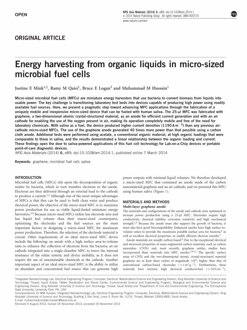
power outputs with minimal liquid volumes. We therefore developeda micro-sized MFC that contained an anode made of the carbonnanomaterial graphene and an air cathode, and we powered this MFCusing human saliva (Figure 1).
MATERIALS AND METHODS
Multi-layer graphene anodeThe materials and configurations of the anode and cathode were optimized to
increase power production using a 25-ml MFC. Electrodes require high
conductivity, chemical stability, corrosion resistivity and high mechanical
strength.1,5 Because the anode must also support the growth of bacteria, it
must also have good biocompatibility. Enhanced anodes have high surface-to-
volume ratios to provide the maximum possible surface area for bacteria,6 as
well as excellent electrical properties, to enable efficient electron transfer.7
Anode materials are usually carbon based.8 Due to the exceptional electrical
and structural properties of nano-engineered carbon materials, such as carbon
nanotubes (CNTs) and, most recently, graphene oxides, studies have
incorporated these materials into MFC anodes.7,9–12 The specific surface
areas of CNTs and the two-dimensional atomic crystal-structured material
graphene are at least three orders of magnitude (103) higher than that of
conventional carbon-based electrodes (o1 m2 g�1). Furthermore, these
materials have intrinsic high electrical conductivities (410 S cm�1),
1Integrated Nanotechnology Lab, Electrical Engineering Program, Computer, Electrical, Mathematical Science and Engineering Division, King Abdullah University of Science andTechnology, Thuwal, Saudi Arabia; 2Water Desalination and Reuse Center, Environmental Science and Engineering Program, Biological and Environmental Science andEngineering Division, King Abdullah University of Science and Technology, Thuwal, Saudi Arabia and 3Department of Civil and Environmental Engineering, The PennsylvaniaState University, University Park, PA, USACorrespondence: Dr MM Hussain, Integrated Nanotechnology Lab, Electrical Engineering Program, Computer, Electrical, Mathematical Science and Engineering Division, KingAbdullah University of Science and Technology, Building 3 (Ibn Sina), Level 3, Room No. 3.274, Thuwal, Makkah 23955-6900, Saudi Arabia.E-mail: [email protected]
Received 4 August 2013; revised 24 November 2013; accepted 26 November 2013
NPG Asia Materials (2014) 6, e89; doi:10.1038/am.2014.1& 2014 Nature Publishing Group All rights reserved 1884-4057/14
www.nature.com/am
potentially making them ideal anode materials to enhance power densities.13
Most studies have integrated CNTs into existing anode materials, such as
carbon cloth10 or textiles.11 In our previous work, we used multi-walled CNTs
as an anode to produce high current density MFCs.12 Recently, graphene oxide
has also been introduced as a blended anode material in carbon cloth14–16 and
stainless steel.17 We show here, for the first time in any type of MFC, that
anodes can be composed of pure multi-layer graphene rather than a graphene
oxide hybrid. To produce these anodes, multi-layer graphene was synthesized
via the decomposition of methane over copper using atmospheric pressure
chemical vapor deposition. First, 25-mm thick copper foils (99.8%, Alfa Aesar,
Karlsruhe, Germany) were loaded into a 4-inch quartz tube inside a horizontal
furnace. The system was then purged with nitrogen for 5 min to remove any
impurities inside the tube. Then the system temperature was ramped to
1000 1C in 30 min while argon and hydrogen were flowed through the quartz
tube at a rate of 200 and 500 standard cubic centimeters per minute (s.c.c.m.),
respectively, for the initial cleaning of Cu. The sample was then kept under
500 s.c.c.m. of hydrogen for 4 min to remove oxygen and to stabilize the
surfaces of the Cu foils. Methane gas, at a flow rate of 50 s.c.c.m., was
introduced into the tube for 1 min. Thereafter, the growth was terminated, and
the furnace was cooled to room temperature under a flow of nitrogen.
Raman spectroscopy (532 nm laser wavelength) was used to evaluate the
multi-layer graphene synthesized using the aforementioned process. Graphene
was confirmed by optical images and the corresponding Raman spectrum
(Supplementary Figure S1).
Air cathodeMicro-sized MFCs are often constrained by their reliance on a two-chamber
configuration, in which the cathode and anode are separated by a membrane
and the cathode chamber must be refilled with fresh electron acceptors.
Ferricyanide is almost exclusively used in micro-sized MFCs as an electron
acceptor, because it can generally produce higher power densities than more
readily available electron acceptors, such as oxygen, because of its ability to
maintain the cathode potential closer to the theoretical value.5 Ferricyanide
must be continuously refilled, however, making it an unsustainable design
feature for use outside of the laboratory.1,5 Thus, the use of the oxygen present
in air has been explored as an electron acceptor, as it is readily available and
does not need to be regenerated. Air cathodes, which use ambient oxygen as
the electron acceptor, are commonly used in large-scale MFCs, which typically
contain a hydrophobic carbon/polytetrafluoroethylene layer on the air side of
the cathode to prevent water leakage and control oxygen diffusion, as well as a
thin platinum catalyst on the water side, as described previously.18,19 However,
air cathodes have only just recently been introduced into micro-sized MFCs
and usually possess proton exchange membranes that are hot pressed onto a
carbon cloth cathode.20,21 Membranes, however, increase the cost and the
internal resistance of a device, which lowers the overall power production.5,18
Therefore, we designed a single-chamber, membrane-less, micro-sized MFC
with an air cathode, which makes the device completely mobile as it does not
require any chemicals other than the oxygen present in air.
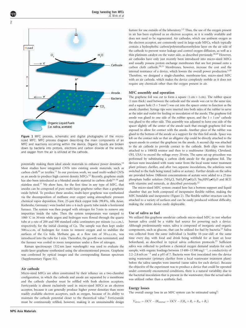
MFC assembly and operationThe graphene foil was cut to form a square (1 cm� 1 cm). The rubber spacer
(1 mm thick) used between the cathode and the anode was cut to the same size,
and a square hole (5� 5 mm2) was cut into the spacer center to function as the
anode chamber. Syringe tips were inserted into both sides of the rubber to serve
as the inlet and outlet for feeding or inoculation of the anode. The graphene foil
anode was glued to one side of the rubber spacer, and the 1� 1 cm2 cathode
was glued to the other side. This assembly was adjusted to leave one side of the
spacer slightly off the center of the anode such that enough graphene foil was
exposed to allow for contact with the anode. Another piece of the rubber was
glued to the bottom of the anode as a support for the thin foil anode. Space was
left on the contact side so that an alligator clip could be directly attached to the
spacer-anode to contact the graphene on the anode. A second clip was attached
to the air cathode to provide contact to the cathode. Both clips were first
attached to a 1000O resistor and then to a multimeter (Keithley, Cleveland,
OH, USA) to record the voltage every 20 min. The same set-up procedure was
performed by substituting a carbon cloth anode for the graphene foil. The
devices were inoculated with waste water from the local waste water treatment
plant primary clarifier, and after two separate inoculations, the solutions were
switched to the fuels being tested (saliva or acetate). Further details on the saliva
are provided below. Different concentrations of acetate were added to a 25 mM
phosphate buffer solution (NH4Cl, NaH2PO4�H2O, Na2HPO4�H2O and KCl)
with vitamins and minerals, as described previously.22
The micro-sized MFC system created here has a bottom support and liquid
chamber that are both composed of inexpensive flexible rubber, making the
MFC bendable and inexpensive (Figure 2). The flexible rubber structure can be
attached to a variety of surfaces and can be easily produced without difficulty,
making the entire device easily deployable.
Use of saliva as fuelWe utilized this graphene anode/air cathode micro-sized MFC to test whether
human saliva could be a viable fuel source for powering such a device.
Although predominantly water, saliva is composed of inorganic and organic
components, such as glucose, that can be utilized for fuel by bacteria.23 Saliva
was collected from the same individual (a healthy 16-year-old) at the same
time every day, with food and drink being withheld for at least an hour
beforehand, as described in typical salvia collection protocols.23 Sufficient
saliva was collected to perform a chemical oxygen demand analysis for each
sample, with organic loadings between 13 400–15 500 mg l�1, a conductivity of
2.2–2.8 mS cm�1 and a pH of 7. Bacteria were first inoculated into the device
using wastewater (primary clarifier from a local wastewater treatment plant)
before the saliva samples were inserted (same saliva for each device). Because
the objective of the experiment was to produce a device that could be operated
under commonly encountered conditions, there is a natural variability due to
the bacterial inoculation that is present in the wastewater; thus the actual saliva
was utilized rather than a synthetic fuel.
Energy lossesThe overall energy loss in an MFC system can be estimated using5:
Vdevice ¼ OCV � IRinternal ¼ OCV � I RaþRc þRmþReð Þ
Figure 1 MFC process, schematic and digital photographs of the micro-
sized MFC. MFC process diagram describing the main components of an
MFC and reactions occurring within the device. Organic liquids are broken
down by bacteria into protons, electrons and carbon dioxide at the anode,and oxygen from the air is utilized at the cathode.
Energy harvesting from MFCsJE Mink et al
2
NPG Asia Materials
where the voltage of the device is equal to the difference between the open
circuit voltage (OCV) and the maximum current (I) times the internal
resistance (Rinternal), which is composed of resistances from the anode (Ra),
cathode (Rc), membrane (Rm) and electrolyte used (Re). The entire energy loss
of the graphene system was approximately 110 mV (OCV 220–90 mV at
maximum power) and 53 mV (OCV 119–66 mV at maximum power) for the
carbon cloth. Because there is no membrane in our system, an entire source of
resistance is eliminated (Rm). The electrolyte or solution resistance can be
estimated using Re¼ d/(AK), where d is the electrode distance (cm), A is the
geometric area available for ionic species to pass (cm2) and K is the specific
conductivity (O�1 cm�1) of the solution. The distance between the anode and
the cathode is approximately 0.1 cm over an area of 5� 5 mm2 in a saliva
solution, with a conductivity of approximately 0.0022O�1 cm�1.
RESULTS
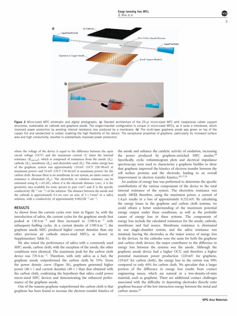
As shown from the current cycles over time in Figure 3a, with theintroduction of saliva, the current cycles for the graphene anode firstpeaked at 130 A m�3 and then increased to 1190 A m�3 withsubsequent fuelling cycles. At a current density of 1190 A m�3, thegraphene anode MFC produced higher current densities than anyother previous air cathode micro-sized MFCs, as shown inSupplementary Table S1.
We also tested the performance of saliva with a commonly usedMFC anode, carbon cloth; with the exception of the anode, the otherconditions were identical. The maximum peak for the carbon clothdevice was 770 A m�3. Therefore, with only saliva as a fuel, thegraphene anode outperformed the carbon cloth by 55%. Fromthe power density curve (Figure 3b), graphene generated higherpower (60� ) and current densities (40� ) than that obtained withthe carbon cloth, confirming the hypothesis that saliva could powermicro-sized MFC devices and demonstrating the enhanced perfor-mance of the graphene anode.
One of the reasons graphene outperformed the carbon cloth is thatgraphene has been found to increase the electron transfer kinetics of
the anode and enhance the catalytic activity of oxidation, increasingthe power produced by graphene-enriched MFC anodes.24
Specifically, cyclic voltammogram plots and electrical impedancespectroscopy were used to characterize a graphene biofilm to showthat graphene improved the kinetics of electron transfer between thecell surface proteins and the electrode, leading to an overallimprovement in electron transfer kinetics.16,17,24
An analysis of energy loss was performed to determine the specificcontributions of the various components of the device to the totalinternal resistance of the system. The electrolyte resistance wasnearly 180O; therefore, using the maximum power, a current of1.4mA results in a loss of approximately 0.252 mV. By calculatingthe energy losses in the graphene and carbon cloth systems, wecould obtain a better understanding of the maximum potentialenergy output under these conditions, as well as the probablecauses of energy loss in these systems. The components ofenergy loss include the calculated resistances for the anode, cathode,membrane and fuel source. Membrane resistance is eliminatedin our single-chamber system, and the saliva resistance wasminimal, leaving the electrodes as the major source of energy lossin the devices. As the cathodes were the same for both the grapheneand carbon cloth devices, the major contributor to the difference inenergy loss between the systems was the anode. Although thegraphene anode device had a higher OCV, and therefore a higherpotential maximum power production (220 mV for graphene,119 mV for carbon cloth), the energy loss in the system was 50%compared to only 44% for carbon cloth. We speculate that a largerportion of the difference in energy loss results from contactengineering issues, which are natural in a low-density-of-statematerial, such as graphene. There are additional contact challengesassociated with the difficulty in depositing electrodes directly ontographene because of the low interaction energy between the metal andcarbon atoms.25
Figure 2 Micro-sized MFC schematic and digital photographs. (a) Stacked architecture of the 25-ml micro-sized MFC with inexpensive rubber support
structures, sustainable air cathode and graphene anode. The single-chamber configuration is unique in micro-sized MFCs, as it lacks a membrane, which
improved power production by avoiding internal resistance loss produced by a membrane. (b) The multi-layer graphene anode was grown on top of the
copper foil and sandwiched in rubber, enabling the high flexibility of the device. The exceptional properties of graphene, particularly its increased surface
area and high conductivity, resulted in substantially improved power production.
Energy harvesting from MFCsJE Mink et al
3
NPG Asia Materials
To confirm that graphene was acting as an MFC anode rather thanrelying on the copper foil alone as an anode or as a complete galvaniccell,26 we fabricated two identical micro-sized MFCs and insertedcopper foil, with and without graphene, as anodes. Both devices wereoperated under the same conditions, with the graphene anodeoutperforming the copper control by 4260% in power density and4160% in current density (see Supplementary Material). As bothanodes were made with the same copper foil, both would haveexperienced similar amounts of additional current from galvanicreactions, which does not diminish the difference in power andcurrent values observed between the graphene anode and the coppercontrol, but may exhibit slightly higher values in maximum powerproduced.5 The improved performance of the graphene devicesupported our assertion that graphene was acting as an MFC anode.
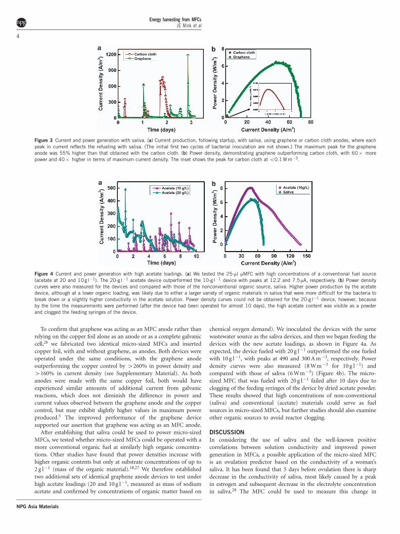
After establishing that saliva could be used to power micro-sizedMFCs, we tested whether micro-sized MFCs could be operated with amore conventional organic fuel at similarly high organic concentra-tions. Other studies have found that power densities increase withhigher organic contents but only at substrate concentrations of up to2 g l�1 (mass of the organic material).18,27 We therefore establishedtwo additional sets of identical graphene anode devices to test underhigh acetate loadings (20 and 10 g l�1, measured as mass of sodiumacetate and confirmed by concentrations of organic matter based on
chemical oxygen demand). We inoculated the devices with the samewastewater source as the saliva devices, and then we began feeding thedevices with the new acetate loadings, as shown in Figure 4a. Asexpected, the device fueled with 20 g l�1 outperformed the one fueledwith 10 g l�1, with peaks at 490 and 300 A m�3, respectively. Powerdensity curves were also measured (8 Wm�3 for 10 g l�1) andcompared with those of saliva (6 Wm�3) (Figure 4b). The micro-sized MFC that was fueled with 20 g l�1 failed after 10 days due toclogging of the feeding syringes of the device by dried acetate powder.These results showed that high concentrations of non-conventional(saliva) and conventional (acetate) materials could serve as fuelsources in micro-sized MFCs, but further studies should also examineother organic sources to avoid reactor clogging.
DISCUSSION
In considering the use of saliva and the well-known positivecorrelations between solution conductivity and improved powergeneration in MFCs, a possible application of the micro-sized MFCis an ovulation predictor based on the conductivity of a woman’ssaliva. It has been found that 5 days before ovulation there is sharpdecrease in the conductivity of saliva, most likely caused by a peakin estrogen and subsequent decrease in the electrolyte concentrationin saliva.28 The MFC could be used to measure this change in
Figure 3 Current and power generation with saliva. (a) Current production, following startup, with saliva, using graphene or carbon cloth anodes, where each
peak in current reflects the refueling with saliva. (The initial first two cycles of bacterial inoculation are not shown.) The maximum peak for the graphene
anode was 55% higher than that obtained with the carbon cloth. (b) Power density, demonstrating graphene outperforming carbon cloth, with 60� more
power and 40� higher in terms of maximum current density. The inset shows the peak for carbon cloth at o0.1 W m�3.
Figure 4 Current and power generation with high acetate loadings. (a) We tested the 25-ml mMFC with high concentrations of a conventional fuel source
(acetate at 20 and 10 g l�1). The 20-g l�1 acetate device outperformed the 10-g l�1 device with peaks at 12.2 and 7.5mA, respectively. (b) Power density
curves were also measured for the devices and compared with those of the nonconventional organic source, saliva. Higher power production by the acetate
device, although at a lower organic loading, was likely due to either a larger variety of organic materials in saliva that were more difficult for the bacteria to
break down or a slightly higher conductivity in the acetate solution. Power density curves could not be obtained for the 20-g l�1 device, however, because
by the time the measurements were performed (after the device had been operated for almost 10 days), the high acetate content was visible as a powder
and clogged the feeding syringes of the device.
Energy harvesting from MFCsJE Mink et al
4
NPG Asia Materials
conductivity to identify the fertility period of a woman, whilesimultaneously using the power generated to send the data to areadily available device, such as a smart phone. This application couldthus help to maintain a woman’s health, as well as help couples inbetter family planning in a non-invasive, easy-to-use method.
This study is a first step in utilizing saliva and other highlyconcentrated organic fuels to power bio-electronics and holds greatpotential for further applications in this field. By producing nearly1mW in power, this saliva-powered, micro-sized MFC already gen-erates enough power to be directly used as an energy harvester inmicroelectronic applications. With the emergence of the field of ultra-low power chip-level biomedical electronics, devices able to operate atsub-microwatt power outputs are becoming a reality.29,30 For example,an electroencephalograph seizure detection system-on-chipintegrating a novel circuit architecture that required o1mW powerwas demonstrated,31 making our production of 0.9mW a competitivedevice for energy harvesting for such applications. Micro-sized MFCsare an interesting and practical energy harvesting option for healthand environmental monitoring system-on-chips. An advantage of theMFC as an energy harvester is the ability to utilize abundant liquidfuel sources, complementing other widely known energy harvesters,such as photovoltaic, thermoelectric and piezoelectric systems, whichuse a different set of fuel resources. Future research on micro-sizedMFCs should explore new methods to increase the power productionof the MFC into the mW range, making it usable in a larger variety ofapplications. A recent study, based on assembling three MFCs in aseries, demonstrated the ability to produce 100mW of power fromindividual reactors, which produced 80mA of current each.32
Improvements in the cathode size and efficiency could also increasepower production.18 Additionally, creating a more efficient aircathode, one specifically designed for the micro-sized MFC, isessential for improving power production.
CONFLICT OF INTERESTThe authors declare no conflict of interest.
ACKNOWLEDGEMENTSWe would like to thank Professor Gary Amy, from KAUST, for providing us
with laboratory space in the Water Desalination and Reuse Center; Dr
Christiane Hoppe-Jones for help with liquid characterization; Daniah Assaadi,
from KAUST, for taking the photographs; Shaiza Sinha and Mariam Mahmoud
for help with the MFC assembly; and Olga Zausalina for helping with the
preparation of the graphics.
Author contributions: MMH, JEM, and BEL conceived the experiments.
MMH directed the experiments. JEM performed the experiments. RMQ
synthesized and characterized the graphene. JEM and BEL analyzed the data.
JEM and MMH co-wrote the manuscript. All authors discussed the results and
helped with the preparation of the final manuscript.
1 Logan, B. Microbial Fuel Cells. 1st edn (John Wiley & Sons, Inc., Hoboken, NJ, USA,2008).
2 Lovley, D. Bug juice: harvesting electricity with microorganisms. Nat. Rev. Microbiol. 4,
497–508 (2006).3 Qian, F. & Morse, D. Miniaturizing microbial fuel cells. Trends Biotechnol. 29, 62–69
(2011).4 Wang, H., Bernarda, A., Huang, C., Lee, D. & Chang, J. Microsized microbial fuel cells:
a mini-review. Bioresour. Technol. 102, 235–242 (2011).5 Logan, B. E., Hamelers, B., Rozendal, R., Schroder, W., Keller, J., Freguia, S.,
Aelterman, P., Verstaete, W. & Rabaey, K. Microbial fuel cells: methodology andtechnology. Environ. Sci. Technol. 40, 5181–5192 (2006).
6 Wei, J., Liang, P. & Huang, X. Recent progress in electrodes for microbial fuel cells.Bioresour. Technol. 102, 9335–9344 (2011).
7 Alatraktchi, F., Zhang, Y., Noori, J. & Angelidaki, I. Surface area expansion ofelectrodes with grass-like nanostructures and gold nanoparticles to enhance electricitygeneration in microbial fuel cells. Bioresour. Technol. 123, 177–183 (2012).
8 Logan, B., Cheng, S., Watson, V. & Estadt, G. Graphite fiber brush anodes for increasedpower production in air-cathode microbial fuel cells. Environ. Sci. Technol. 41,
3341–3346 (2007).9 Inoue, S., Parra, E. A., Higa, A., Jiang, Y., Wang, P., Buie, C. R., Coates, J. D. & Lin, L.
Structural optimization of contact electrodes in microbial fuel cells for current densityenhancements. Sensor Actuat. A Phys. 177, 30–36 (2012).
10 Tsai, H. Y., Wu, C. C., Lee, C. Y. & Shih, E. P. Microbial fuel cell performance ofmultiwall carbon nanotubes on carbon cloth as electrodes. J. Power Sources 194,
199–205 (2009).11 Xie, X., Hu, L., Pasta, M., Wells, G. F., Kong, D., Criddle, C. S. & Cui, Y. Three
dimensional carbon nanotube-textile anode for high-performance microbial fuel cells.Nano Lett. 11, 291–296 (2011).
12 Mink, J. E., Rojas, J. P., Logan, B. E. & Hussain, M. M. Vertically grown multiwalledcarbon nanotube anode and nickel silicide integrated high performance microsized(1.25 mL) microbial fuel cell. Nano Lett. 12, 791–795 (2012).
13 Gadhamshetty, V. & Koratkar, N. Nano-engineered biocatalyst electrode structures fornext generation microbial fuel cells. Nano Energy 1, 3–5 (2012).
14 Xiao, L., Damien, J., Luo, J., Jang, H., Huang, J. & He, Z. Crumbled graphene particlesfor microbial fuel cell electrodes. J. Power Sources 208, 187–192 (2012).
15 Liu, J., Qiao, Y., Guo, C., Lim, S., Song, H. & Li, C. Graphene/carbon cloth anode forhigh-performance mediatorless microbial fuel cells. Bioresour. Technol. 114, 275–280(2012).
16 Yuan, Y., Zhou, S., Zhao, B., Zhuang, L. & Wang, Y. Microbially-reduced graphenescaffolds to facilitate extracellular electron transfer in microbial fuel cells. Bioresour.Technol 116, 453–458 (2012).
17 Zhang, Y., Mo, G., Li, X., Zhang, W., Zhang, J., Ye, J., Huang, Xiaodan & Yu, C.A graphene modified anode to improve the performance of microbial fuel cells.J. Power Sources 196, 5402–5407 (2011).
18 Cheng, S. & Logan, B. E. Increasing power generation for scaling up single-chamber aircathode microbial fuel cells. Bioresour. Technol. 102, 4468–4473 (2011).
19 Cheng, S., Liu, H. & Logan, B. Increased performance of single-chamber microbial fuelcells using an improved cathode structure. Electrochem. Commun. 8, 489–494(2006).
20 Hou, H., Li, L., De Figueiredo, P. & Han, A. Air-cathode microbial fuel cell array: adevice for identifying and characterizing electrochemically active microbes. Biosens.Bioelectron. 26, 2680–2684 (2011).
21 Chen, Y., Zhao, Y., Qui, K., Chu, J., Lu, R., Sun, M., Liu, X., Sheng, G., Yu, H., Chen, J.,Li, W., Liu, G., Tian, Y. & Xiong, Y. An innovative miniature microbial fuel cell fabricatedusing photolithography. Biosens. Bioelectron. 26, 2841–2846 (2011).
22 Lovley, D. R. & Phillips, E. J. P. Novel mode of microbial energy metabolism: organiccarbon oxidation coupled to dissimilatory reduction of iron or manganese. Appl.Environ. Microbiol. 54, 1472–1480 (1988).
23 Chiappin, S., Antonelli, G., Gattie, R. & De Palo, E. F. Saliva specimen: a newlaboratory tool for diagnostic and basic investigation. Clin. Chim. Acta 383, 30–40(2007).
24 Yong, Y., Dong, X., Chan-Park, M., Song, H. & Chen, P. Macroporous and monolithicanode based on polyaniline hybridized three-dimensional graphene for high-perfor-mance microbial fuel cells. ACS Nano 6, 2394–2400 (2012).
25 Matsuda, Y., Deng, W. Q. & Goddard, W. A. III Contact resistance propertiesbetween nanotubes and various metals from quantum mechanics. J. Phys. Chem.111, 11113–11116 (2007).
26 Logan, B. E. Essential data and techniques for conducting microbial fuel cell and othertypes of bioelectrochemical system experiments. Chem. Sus. Chem. 5, 988–994 (2012).
27 Min, B. & Logan, B. E. Continuous electricity generation from domestic wastewaterand organic substrates in a flat plate microbial fuel cell. Environ. Sci. Technol. 38,
5809–5814 (2004).28 Huang, Z., Wu, Z., Zhou, F. & Zhou, J. Ovulation prediction by monitoring the
conductivity of woman’s saliva. IEEE/EMBS Proc. 5, 2344–2346 (1997).29 Sarpeshkar, R. Ultra Low Power Bioelectronics: Fundamentals, Biomedical Applications,
and Bio-inspired Systems (Cambridge University Press, Cambridge, MA, USA, 2010).30 Chandrakasan, A., Verma, N. & Daly, D. Ultralow-power electronics for biomedical
applications. Annu. Rev. Biomed. Eng. 10, 247–274 (2008).31 Sridhara, S., Direnzo, M., Lingam, S., Lee, S., Blazquez, R., Maxey, J., Ghanem, S.,
Lee, Y., Abdallah, R., Singh, P. & Goel, M. Microwatt embedded processor platform formedical system-on-chip applications. Symp. VLSI Circuits 15–16 (2010).
32 Choi, S. & Chae, J. An array of microliter-sized microbial fuel cells generating 100 mWof power. Sensor Actuat. A Phys. 177, 10–15 (2012).
This work is licensed under a Creative CommonsAttribution-NonCommercial-NoDerivs 3.0 Unported
License. To view a copy of this license, visit http://creativecommons.org/licenses/by-nc-nd/3.0/
Supplementary Information accompanies the paper on the NPG Asia Materials website (http://www.nature.com/am)
Energy harvesting from MFCsJE Mink et al
5
NPG Asia Materials


![Redox-active Ionic Liquids for Energy Harvesting and Storage Applications · electrochemical applications, in particular in “green chemistry” [2–4] in tuning their unique chemical](https://img.pdfslide.net/doc/110x75/5f7b5b1d4a9b5a5065612ead/redox-active-ionic-liquids-for-energy-harvesting-and-storage-applications-electrochemical.jpg)