Embed Size (px)
Citation preview

Energy Measurement and Management
Index:
MT174 – Electronic three-phase time-of-use electricity meters ........................................... 3
MT174 meter properties: ......................................... 4 1. Meter appearance .......................................... 6 1.1. Meter case ....................................................... 6 1.2. Terminal block ................................................. 6 1.2.1. Terminal block for direct connected meters 6 1.2.2. Auxiliary terminals ....................................... 7 1.3. Over-all dimensions ......................................... 8 2. Meter configuration ....................................... 8 2.1. Metering elements ........................................... 8 2.2. Power supply stage ......................................... 9 2.3. Microcontroller ................................................. 9 2.3.1. Load-profile recorder ................................... 9 2.3.2. Log-book ..................................................... 9 2.3.3. Billing results keeping ............................... 10 2.4. Real-time clock .............................................. 10 2.4.1. RTC back-up power supply ....................... 10 2.4.2. RTC accuracy testing ................................ 10 2.4.3. Time-of-use registration ............................ 11 2.4.4. Maximum demand measurement ............. 11 2.4.5. Meter billing reset ...................................... 11 2.5. LCD ............................................................... 11 2.5.1. LCD testing ............................................... 12 2.5.2. Data display .............................................. 12 2.5.3. Signal and alarm flags .............................. 12 2.5.4. No-power reading option ........................... 13 2.6. LEDs .............................................................. 13 2.7. Push-buttons ................................................. 14 2.7.1. Display testing ........................................... 14
2.7.2. Manual data display ................................... 14 2.7.3. Manual meter billing reset ......................... 15 2.7.4. Meter setting mode .................................... 15 2.7.5. Meter testing mode .................................... 16 2.8. Communication channels .............................. 17 2.8.1. Optical port ................................................ 17 2.8.2. RS485 interface ......................................... 17 2.8.3. Data downloaded via optical port .............. 17 2.8.4. Fatal error register ..................................... 18 2.8.5. Communication protocol ............................ 18 2.9. Inputs and outputs ......................................... 18 2.9.1. Tariff input .................................................. 18 2.9.2. Pulse output ............................................... 18 2.9.3. Tariff output ................................................ 19 2.10. Detectors of opening meter cover and terminal
cover .............................................................. 19 3. Antifraud protection .................................... 19 3.1. Meter seals .................................................... 19 3.2. Always positive registration ........................... 19 3.3. Passwords ..................................................... 19 3.4. Parameters change protected with a sealed
pushbutton ..................................................... 20 3.5. Cover(s) opening detector(s) ......................... 20 3.6. Detector of external magnetic field ................ 20 3.7. Fourth metering element ................................ 20 3.8. Fraud event counters ..................................... 20 3.9. Registers of elapsed time .............................. 20 3.10. Registers of fraud energy .............................. 21 3.11. Log-books ...................................................... 21 3.12. SEP2 MeterView software ............................. 21
MT174 Three-Phase Static Electricity Multi Tariff Meter with Maximum Demand Indicator and Load-profile
Technical Description Version 1.0, 05.05.2010
Energy Measurement and Management
4. Tools for meter managing........................... 21 5. Meter maintenance ...................................... 21 6. Meter connection diagram .......................... 21 7. Technical data .............................................. 22
8. Meter type designation ............................... 23 9. Appendix: EDIS codes, data stored in
registers, sequences, historical values .... 24
3 of 30
MT174 ─ Electronic three-phase electricity meters
with maximum demand and LP
MT174 – Electronic three-phase time-of-use electricity meters The MT174 electronic three-phase meters are designed for measurement and registration of active, reactive and apparent energy and demand in three-phase four-wire networks. They can be connected directly to the network. The metering and technical properties of the meters comply with the EN 50470-1 and -3 European standards for active energy meters, classes A and B, as well as with the IEC 62053-21 and IEC 62052-11 international standards for electronic meters of active energy for classes 1 and 2, and optionally with the IEC 62053-23 international standard for electronic meters of reactive energy for classes 2 and 3. A built-in time-switch complies with the IEC 62054-21 and IEC 62052-21 standards. It enables energy registration in up to four tariffs. The meter software complies with WELMEC 7.2 Issue 1 Software Guide (Measuring Instruments Directive 2004/22/EC) The meters are designed and manufactured in compliance with the ISO 9001 (2000) standard.
MT174 meters belong to the MT17x meters family, together with the MT171 and the MT173 meters. Common characteristics of the MT17x meters family are:
a. the same measuring system
b. the same meter case
c. the same terminal blocks
d. Multi-tariff registration (max. 4 tariffs))
e. LCD complies with VDEW requirements
f. Communication protocol IEC 62056-21, Mode C
The MT174 meters differ from the other meters that belong to the MT17x meter family in:
a. Measurement by phases
b. Measurement in neutral circuit (optional)
c. Measurement of apparent energy
d. Measurement of other quantities (currents, voltages, power factors, instantaneous power and frequency)
e. Powerful 8-channel load-profile recorder
f. Communication channels:
- RS485 interface
g. Powerful log-book
h. Countermeasures against fraud
4 of 30
MT174 ─ Electronic three-phase electricity meters
with maximum demand and LP
MT174 meter properties:
Meter accuracy
Class A or B in compliance with EN 50470-3
(or 2 or 1 in compliance with IEC 62053-21)
for active energy
Class 3 or 2 for reactive energy (option)
Class 3 or 2 for apparent energy (option)
Meter software in compliance with WELMEC 7.2 Issue 1
Measured quantities
Energy (active, reactive and apparent)
Demand (active, reactive and apparent)
Reactive energy and demand by quadrants
Instantaneous power
Phase voltages (UL1, UL2, UL3)
Phase currents (IL1, IL2, IL3)
Phase power factors
Frequency
Modes of energy measurement and registration
For one-way energy flow direction (import), with an electronic reverse running stop
For two energy flow directions (import, export)
For two-way energy flow direction, with al-ways positive registration, i.e. energy flowing in the export direction is registered as it flows in import direction too (only for active energy)
Connection:
Direct
Networks:
3-phase 4-wire
3-phase 3-wire
1-phase 2-wire
Meter quality:
Due to high accuracy and long term stability of the metering elements no meter recalib-ration is required over its lifetime
Long meter lifetime and high meter reliability
High immunity to EMC
RTC:
Accuracy better than ±3 min/year at 23°C
RTC operation reserve 5 years
Back-up power supply Li-battery
Indication of low Li-battery (option)
Time-of-use registration (up to 4 tariffs):
Tariffs change-over by internal real-time clock
Optional tariff inputs for external tariff change-over
LCD:
Large LCD in compliance with the VDEW requirements
EDIS code for data identification
LCD back-light on request
Data display modes:
Automatic cyclic data display with default display time of 5 sec.
Manual data display mode (by pressing the Scroll push-button)
Optional data display when the meter is in no-power state
Indicators:
LCD:
- Valid tariff at the moment
- Meter status and alarms
- Energy flow direction
- Phase voltage presence and phase voltage sequence
- reversed energy flow through a particular metering element
LEDs:
- Imp/kWh
- Imp/kvarh (at active and reactive energy
meters)
- Imp/kVAh (at kWh-, kvarh-, kVAh-meters)
Powerful load-profile recorder:
Up to 8-channels
730 days of registration at 1 channel, 1-hour registration period
Communication channels:
Infrared optical port in compliance with IEC 62056-21 for local programming and data down-loading
RS485 interface (option)
Protocol IEC 62056 – 21, mode C
Pulse outputs:
Class A by IEC 62053-31 (option)
Optomos relay with make contact (option)
Plastic meter case:
Made of high quality self-extinguishing UV stabilized material that can be recycled
Double insulation
IP54 protection against dust and water penetration (by IEC 60529)
5 of 30
MT174 ─ Electronic three-phase electricity meters
with maximum demand and LP
At direct connected meters:
Current terminals
- Assure good connection with all types of conductors
- Do not damage conductors
Potential links
- Sliding self-braking potential links enable quick disconnection of current and voltage circuitries
- Can be located in a terminal block com- partment or under a meter cover
Antifraud functions:
Detectors (optional)
- meter cover opening
- terminal cover opening
- reversed energy flow direction
- permanent magnet field
Indicators (optional)
- meter cover opening
- terminal cover opening
- reversed energy flow direction trough each of metering elements
- permanent magnet field
Fraud energy registers (optional)
- energy consumed since the meter cover has been opened
- energy consumed since the terminal cover has been opened
- energy consumed since reversed energy flow has been detected
- energy consumed since permanent magnet field has been detected
- energy consumed since neutral tampering has been detected
Counters of events (optional)
- meter cover opening
- terminal cover opening
- reversed energy flow direction
- permanent magnet field
Counters of elapsed time (optional)
- since meter cover has been opened
- since terminal cover has been opened
- since reversed energy flow has been detected
- since permanent magnet field has been detected
- of total energy registration
- of energy registration in a particular tariff
- since neutral tampering has been detected
Time-stamps (optional)
- of the last meter cover opening
- of the last terminal cover opening
- of the last reversed energy flow detection
- of the last permanent magnet field tampering
Change of set parameters protected with a sealed pushbutton (optional)
Metering element in neutral (optional)
6 of 30
MT174 ─ Electronic three-phase electricity meters
with maximum demand and LP
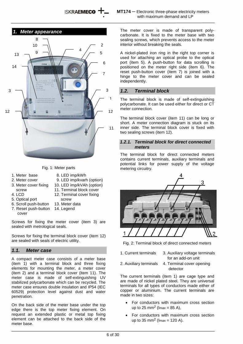
1. Meter appearance
Fig. 1: Meter parts
1. Meter base 8. LED imp/kWh 2. Meter cover 9. LED imp/kvarh (option)
3. Meter cover fixing screw
10. LED imp/kVAh (option) 11. Terminal block cover
4. LCD 12. Terminal cover fixing 5. Optical port screw 6. Scroll push-button 13. Meter data 7. Reset push-button
cover 14. Legend
Screws for fixing the meter cover (item 3) are sealed with metrological seals. Screws for fixing the terminal block cover (item 12) are sealed with seals of electric utility.
1.1. Meter case
A compact meter case consists of a meter base (item 1) with a terminal block and three fixing elements for mounting the meter, a meter cover (item 2) and a terminal block cover (item 11). The meter case is made of self-extinguishing UV stabilized polycarbonate which can be recycled. The meter case ensures double insulation and IP54 (IEC 60529) protection level against dust and water penetration.
On the back side of the meter base under the top edge there is the top meter fixing element. On request an extended plastic or metal top fixing element can be attached to the back side of the meter base.
The meter cover is made of transparent poly-carbonate. It is fixed to the meter base with two sealing screws, which prevents access to the meter interior without breaking the seals.
A nickel-plated iron ring in the right top corner is used for attaching an optical probe to the optical port (item 5). A push-button for data scrolling is positioned on the meter right side (item 6). The reset push-button cover (item 7) is joined with a hinge to the meter cover and can be sealed independently.
1.2. Terminal block
The terminal block is made of self-extinguishing polycarbonate. It can be used either for direct or CT meter connection. The terminal block cover (item 11) can be long or short. A meter connection diagram is stuck on its inner side. The terminal block cover is fixed with two sealing screws (item 12).
1.2.1. Terminal block for direct connected meters
The terminal block for direct connected meters contains current terminals, auxiliary terminals and potential links for power supply of the voltage metering circuitry.
Fig. 2: Terminal block of direct connected meters
1. Current terminals 3. Auxiliary voltage terminals
for an add-on unit
2. Auxiliary terminals 4. Terminal cover opening
detector
The current terminals (item 1) are cage type and are made of nickel plated steel. They are universal terminals for all types of conductors made either of copper or aluminium. The current terminals are made in two sizes:
For conductors with maximum cross section
up to 25 mm2 (Imax = 85 A),
For conductors with maximum cross section
up to 35 mm2 (Imax = 120 A).
1
11
3 3
4 5
6
8
12 12
13
14
7
2
9
10
7 of 30
MT174 ─ Electronic three-phase electricity meters
with maximum demand and LP
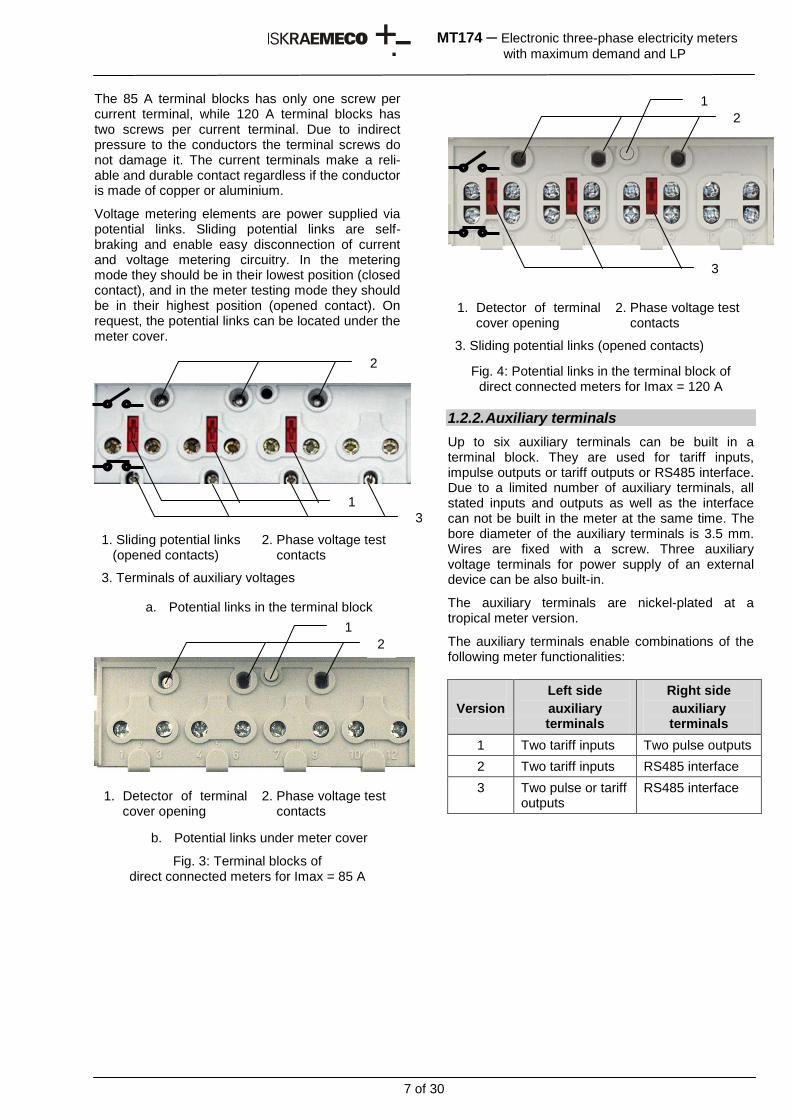
The 85 A terminal blocks has only one screw per current terminal, while 120 A terminal blocks has two screws per current terminal. Due to indirect pressure to the conductors the terminal screws do not damage it. The current terminals make a reli-able and durable contact regardless if the conductor is made of copper or aluminium.
Voltage metering elements are power supplied via potential links. Sliding potential links are self-braking and enable easy disconnection of current and voltage metering circuitry. In the metering mode they should be in their lowest position (closed contact), and in the meter testing mode they should be in their highest position (opened contact). On request, the potential links can be located under the meter cover.
1. Sliding potential links (opened contacts)
2. Phase voltage test contacts
3. Terminals of auxiliary voltages
a. Potential links in the terminal block
1. Detector of terminal cover opening
2. Phase voltage test contacts
b. Potential links under meter cover
Fig. 3: Terminal blocks of direct connected meters for Imax = 85 A
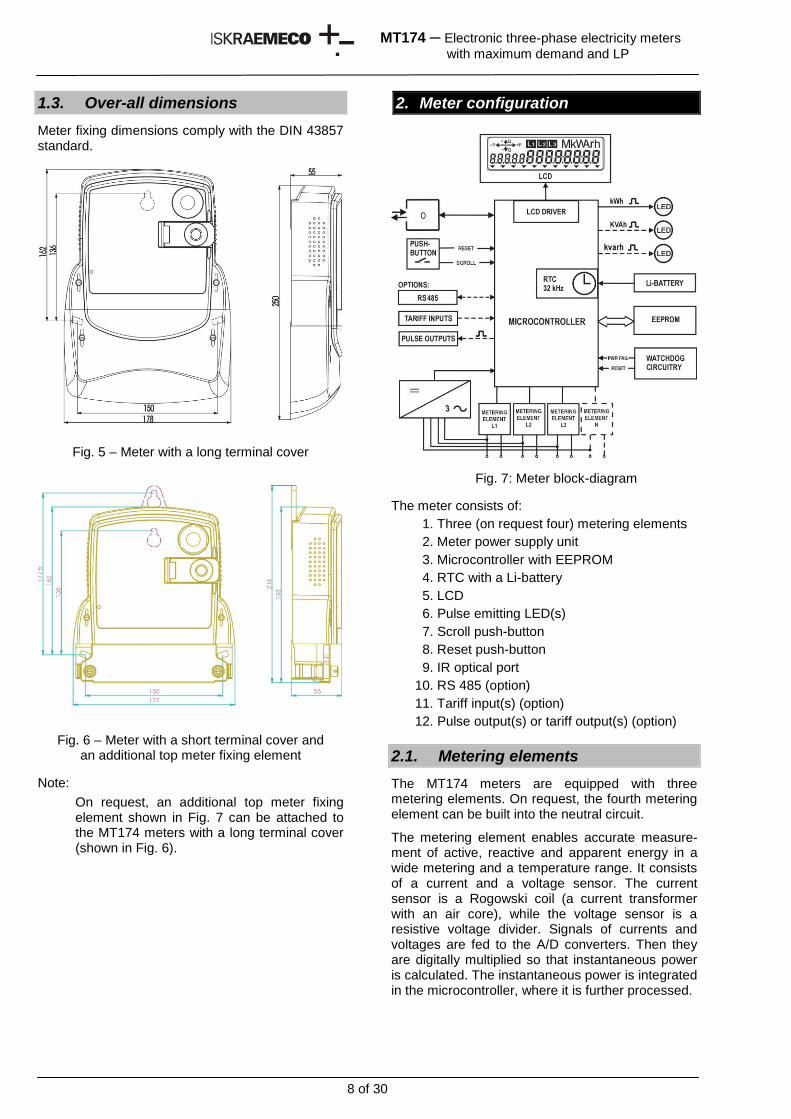
1. Detector of terminal cover opening
2. Phase voltage test contacts
3. Sliding potential links (opened contacts)
Fig. 4: Potential links in the terminal block of direct connected meters for Imax = 120 A
1.2.2. Auxiliary terminals
Up to six auxiliary terminals can be built in a terminal block. They are used for tariff inputs, impulse outputs or tariff outputs or RS485 interface. Due to a limited number of auxiliary terminals, all stated inputs and outputs as well as the interface can not be built in the meter at the same time. The bore diameter of the auxiliary terminals is 3.5 mm. Wires are fixed with a screw. Three auxiliary voltage terminals for power supply of an external device can be also built-in.
The auxiliary terminals are nickel-plated at a tropical meter version.
The auxiliary terminals enable combinations of the following meter functionalities:
Version
Left side
auxiliary terminals
Right side
auxiliary terminals
1 Two tariff inputs Two pulse outputs
2 Two tariff inputs RS485 interface
3 Two pulse or tariff outputs
RS485 interface
2
1
3
2
1
2
1
3
8 of 30
MT174 ─ Electronic three-phase electricity meters
with maximum demand and LP
1.3. Over-all dimensions
Meter fixing dimensions comply with the DIN 43857 standard.
Fig. 5 – Meter with a long terminal cover
Fig. 6 – Meter with a short terminal cover and an additional top meter fixing element
Note:
On request, an additional top meter fixing element shown in Fig. 7 can be attached to the MT174 meters with a long terminal cover (shown in Fig. 6).
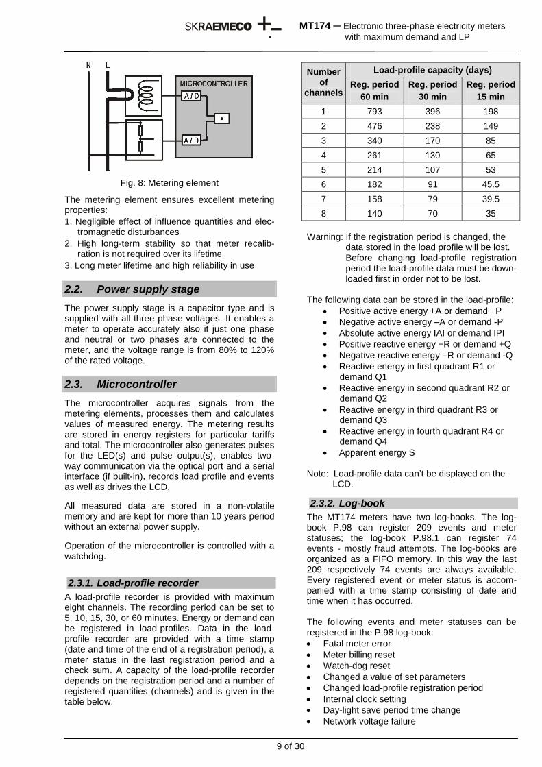
2. Meter configuration
Fig. 7: Meter block-diagram
The meter consists of:
1. Three (on request four) metering elements
2. Meter power supply unit
3. Microcontroller with EEPROM
4. RTC with a Li-battery
5. LCD
6. Pulse emitting LED(s)
7. Scroll push-button
8. Reset push-button
9. IR optical port
10. RS 485 (option)
11. Tariff input(s) (option)
12. Pulse output(s) or tariff output(s) (option)
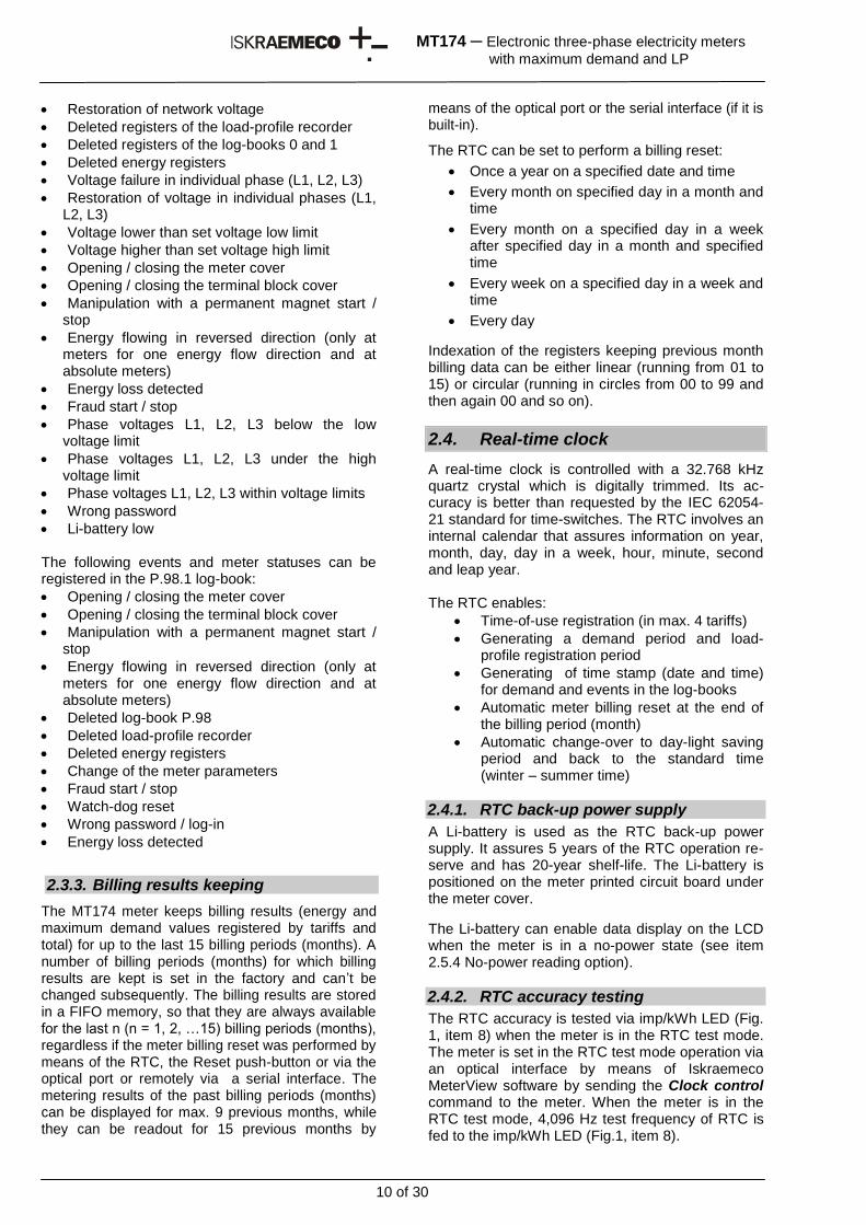
2.1. Metering elements
The MT174 meters are equipped with three metering elements. On request, the fourth metering element can be built into the neutral circuit.
The metering element enables accurate measure-ment of active, reactive and apparent energy in a wide metering and a temperature range. It consists of a current and a voltage sensor. The current sensor is a Rogowski coil (a current transformer with an air core), while the voltage sensor is a resistive voltage divider. Signals of currents and voltages are fed to the A/D converters. Then they are digitally multiplied so that instantaneous power is calculated. The instantaneous power is integrated in the microcontroller, where it is further processed.
9 of 30
MT174 ─ Electronic three-phase electricity meters
with maximum demand and LP
Fig. 8: Metering element
The metering element ensures excellent metering properties:
1. Negligible effect of influence quantities and elec-tromagnetic disturbances
2. High long-term stability so that meter recalib-ration is not required over its lifetime
3. Long meter lifetime and high reliability in use
2.2. Power supply stage
The power supply stage is a capacitor type and is supplied with all three phase voltages. It enables a meter to operate accurately also if just one phase and neutral or two phases are connected to the meter, and the voltage range is from 80% to 120% of the rated voltage.
2.3. Microcontroller
The microcontroller acquires signals from the metering elements, processes them and calculates values of measured energy. The metering results are stored in energy registers for particular tariffs and total. The microcontroller also generates pulses for the LED(s) and pulse output(s), enables two-way communication via the optical port and a serial interface (if built-in), records load profile and events as well as drives the LCD.
All measured data are stored in a non-volatile memory and are kept for more than 10 years period without an external power supply.
Operation of the microcontroller is controlled with a watchdog.
2.3.1. Load-profile recorder
A load-profile recorder is provided with maximum eight channels. The recording period can be set to 5, 10, 15, 30, or 60 minutes. Energy or demand can be registered in load-profiles. Data in the load-profile recorder are provided with a time stamp (date and time of the end of a registration period), a meter status in the last registration period and a check sum. A capacity of the load-profile recorder depends on the registration period and a number of registered quantities (channels) and is given in the table below.
Number of
channels
Load-profile capacity (days)
Reg. period
60 min
Reg. period
30 min
Reg. period
15 min
1 793 396 198
2 476 238 149
3 340 170 85
4 261 130 65
5 214 107 53
6 182 91 45.5
7 158 79 39.5
8 140 70 35
Warning: If the registration period is changed, the
data stored in the load profile will be lost. Before changing load-profile registration
period the load-profile data must be down-loaded first in order not to be lost.
The following data can be stored in the load-profile:
Positive active energy +A or demand +P
Negative active energy –A or demand -P
Absolute active energy IAI or demand IPI
Positive reactive energy +R or demand +Q
Negative reactive energy –R or demand -Q
Reactive energy in first quadrant R1 or demand Q1
Reactive energy in second quadrant R2 or demand Q2
Reactive energy in third quadrant R3 or demand Q3
Reactive energy in fourth quadrant R4 or demand Q4
Apparent energy S Note: Load-profile data can’t be displayed on the
LCD.
2.3.2. Log-book
The MT174 meters have two log-books. The log-book P.98 can register 209 events and meter statuses; the log-book P.98.1 can register 74 events - mostly fraud attempts. The log-books are organized as a FIFO memory. In this way the last 209 respectively 74 events are always available. Every registered event or meter status is accom-panied with a time stamp consisting of date and time when it has occurred. The following events and meter statuses can be registered in the P.98 log-book:
Fatal meter error
Meter billing reset
Watch-dog reset
Changed a value of set parameters
Changed load-profile registration period
Internal clock setting
Day-light save period time change
Network voltage failure
10 of 30
MT174 ─ Electronic three-phase electricity meters
with maximum demand and LP
Restoration of network voltage
Deleted registers of the load-profile recorder
Deleted registers of the log-books 0 and 1
Deleted energy registers
Voltage failure in individual phase (L1, L2, L3)
Restoration of voltage in individual phases (L1, L2, L3)
Voltage lower than set voltage low limit
Voltage higher than set voltage high limit
Opening / closing the meter cover
Opening / closing the terminal block cover
Manipulation with a permanent magnet start / stop
Energy flowing in reversed direction (only at meters for one energy flow direction and at absolute meters)
Energy loss detected
Fraud start / stop
Phase voltages L1, L2, L3 below the low voltage limit
Phase voltages L1, L2, L3 under the high voltage limit
Phase voltages L1, L2, L3 within voltage limits
Wrong password
Li-battery low The following events and meter statuses can be registered in the P.98.1 log-book:
Opening / closing the meter cover
Opening / closing the terminal block cover
Manipulation with a permanent magnet start / stop
Energy flowing in reversed direction (only at meters for one energy flow direction and at absolute meters)
Deleted log-book P.98
Deleted load-profile recorder
Deleted energy registers
Change of the meter parameters
Fraud start / stop
Watch-dog reset
Wrong password / log-in
Energy loss detected
2.3.3. Billing results keeping
The MT174 meter keeps billing results (energy and maximum demand values registered by tariffs and total) for up to the last 15 billing periods (months). A number of billing periods (months) for which billing results are kept is set in the factory and can’t be changed subsequently. The billing results are stored in a FIFO memory, so that they are always available for the last n (n = 1, 2, …15) billing periods (months), regardless if the meter billing reset was performed by means of the RTC, the Reset push-button or via the optical port or remotely via a serial interface. The metering results of the past billing periods (months) can be displayed for max. 9 previous months, while they can be readout for 15 previous months by
means of the optical port or the serial interface (if it is built-in).
The RTC can be set to perform a billing reset:
Once a year on a specified date and time
Every month on specified day in a month and time
Every month on a specified day in a week after specified day in a month and specified time
Every week on a specified day in a week and time
Every day
Indexation of the registers keeping previous month billing data can be either linear (running from 01 to 15) or circular (running in circles from 00 to 99 and then again 00 and so on).
2.4. Real-time clock
A real-time clock is controlled with a 32.768 kHz quartz crystal which is digitally trimmed. Its ac-curacy is better than requested by the IEC 62054-21 standard for time-switches. The RTC involves an internal calendar that assures information on year, month, day, day in a week, hour, minute, second and leap year. The RTC enables:
Time-of-use registration (in max. 4 tariffs)
Generating a demand period and load-profile registration period
Generating of time stamp (date and time) for demand and events in the log-books
Automatic meter billing reset at the end of the billing period (month)
Automatic change-over to day-light saving period and back to the standard time (winter – summer time)
2.4.1. RTC back-up power supply
A Li-battery is used as the RTC back-up power supply. It assures 5 years of the RTC operation re-serve and has 20-year shelf-life. The Li-battery is positioned on the meter printed circuit board under the meter cover.
The Li-battery can enable data display on the LCD when the meter is in a no-power state (see item 2.5.4 No-power reading option).
2.4.2. RTC accuracy testing
The RTC accuracy is tested via imp/kWh LED (Fig. 1, item 8) when the meter is in the RTC test mode. The meter is set in the RTC test mode operation via an optical interface by means of Iskraemeco MeterView software by sending the Clock control command to the meter. When the meter is in the RTC test mode, 4,096 Hz test frequency of RTC is fed to the imp/kWh LED (Fig.1, item 8).
11 of 30
MT174 ─ Electronic three-phase electricity meters
with maximum demand and LP
2.4.3. Time-of-use registration
The meter is designed as a multi-tariff with maxi-mum four tariffs. A tariff change-over time is defined with hour and minute. Minimal time period between change-over is five minutes. The real-time clock enables complex daily and weekly tariff structures, as well as a couple of seasons in a year:
Up to 10 seasons in a year (i.e. 10 weekly tariff programs)
Up to 10 daily definitions of the tariff change-over program
Up to 10 tariff change-over inside individual daily tariff programs
Up to 46 holidays (including those based on a lunar calendar) in which a special tariff program is defined
The tariff programs control both energy end maximum demand registration.
Tariffs can be changed-over also via tariff inputs – maximum two tariff inputs are available for changing-over up to four tariffs. When tariff inputs are used for tariff change-over the active tariff valid both for energy and demand.
2.4.3.1. Holidays
The MT174 meters support the following holidays:
Single (on defined year, a month and a day in a month)
Every year (on defined month and a day in a month)
Every year with shift to Monday (on defined month and a day in a month and if that date is on Sunday, the holiday is shifted to Monday)
Holidays based on Lunar calendar For holidays based on Lunar calendar the reference holiday is Eastern according to Gregorian calendar. All other lunar holidays are defined with a number of days before or after the Eastern for that holiday – shifted days.
2.4.4. Maximum demand measurement
The internal clock generates a demand period for demand calculation. Demand is calculated as a mean value in the integration period. In the MT174 meters the following demand periods can be set: 5, 10, 15, 30 or 60 minutes. At the end of a demand period the calculated demand is transferred from the current demand period register into the register of the demand period that was just terminated. It is compared with the value stored in the maximum demand register in the billing period. If the new calculated demand is greater than the value in the maximum demand register, a new demand value is stored, otherwise the old value is kept. In this way, a maximum demand is also registered at the meter billing reset.
2.4.5. Meter billing reset
A meter billing reset is usually done by RTC once a month. However, any other period of a meter billing reset can also be set (see Item 2.3.3 “Billing results keeping”). Day and time of the meter billing reset can be set for any day in a month and any time during a day. At the meter billing reset the billing data for a current month are copied from the registers for a current month (a billing period) to the registers of a previous month (a billing period) and registers for maximum demand in a current billing period (month) are cleared. At the same time the maximum demand value is added to a sum of maximum demands in the cumulative demand re-gister and a counter of billing resets is incremented.
The meter billing reset can be performed not only by means of RTC but also by pressing the Reset push-button (see Item 2.7.4 “Manual meter billing reset”), via the IR optical port or remotely via a serial interface, if it is built-in.
2.5. LCD
The 7-segment LCD, with additional characters and symbols, complies with the VDEW specifications. Large characters and a wide angle view enable easy data reading. The LCD back-light illumination is available on request. The LCD is illuminated by short (Tp < 2 s) pressing the blue pushbutton. On request the back-light is turned-on all the time.
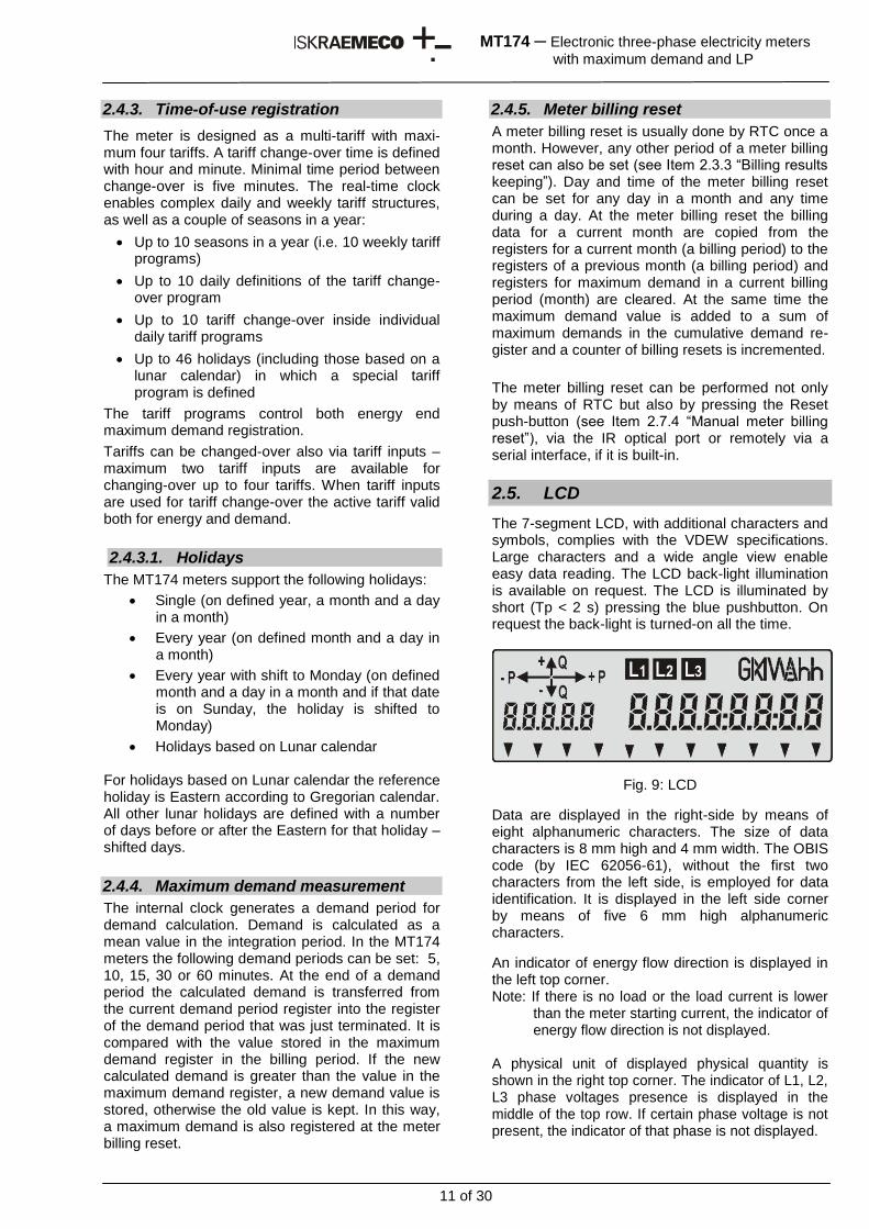
Fig. 9: LCD
Data are displayed in the right-side by means of eight alphanumeric characters. The size of data characters is 8 mm high and 4 mm width. The OBIS code (by IEC 62056-61), without the first two characters from the left side, is employed for data identification. It is displayed in the left side corner by means of five 6 mm high alphanumeric characters.
An indicator of energy flow direction is displayed in the left top corner. Note: If there is no load or the load current is lower
than the meter starting current, the indicator of energy flow direction is not displayed.
A physical unit of displayed physical quantity is shown in the right top corner. The indicator of L1, L2, L3 phase voltages presence is displayed in the middle of the top row. If certain phase voltage is not present, the indicator of that phase is not displayed.
12 of 30
MT174 ─ Electronic three-phase electricity meters
with maximum demand and LP
When the indicators L1L2L3 blink this indicates wrong phase sequence.
When the indicator L1, L2 or L3 blinks and at the same the arrow indicating export energy flow direction is displayed it indicates reverse energy flow through the metering element in that phase. In the LCD bottom row there are eleven signal flags that indicate current valid tariff, meter status and alarms. The meaning of signal flags (see item 2.5.3) is engraved on the meter name plate bellow them.
2.5.1. LCD testing
The LCD can be tested automatically so that all LCD segments are displayed (Fig. 10) for 5 seconds to check if they are in order.
The LCD test can be performed either:
After voltage is applied to the meter
In Auto scroll sequence or
In Manual scroll sequence
With a command sent via a communication interface
2.5.2. Data display
Data defined in Auto scroll sequence and in Manual scroll sequence are displayed on the LCD.
Data from Auto scroll sequence are displayed in a circle. Each data is default displayed for 8 seconds. On request, longer or shorter data display time can be set via the meter optical port by means of Iskraemeco MeterView software.
Note: Maximum 34 registers can be included in the AUTO scroll mode
At Manual scroll sequence the blue push-button should be pressed for displaying the next piece of data. Data in Manual scroll sequence remains displayed until the push-button is pressed again or until time for automatic return into the Auto scroll sequence is elapsed.
On request, billing data for the maximum 9 elapsed billing periods (months) can be displayed in the LCD too.
Note: Maximum 50 registers can be included in the MANUAL scroll mode
Data that can be displayed at different meter con-figurations required by the customer are shown in the table in the Appendix: Data registers and sequences.
Energy data and demand can be displayed in data formats given in the table below.
Data format No. of integers No. of decimals
Energy
6.0 6 0
7.1 6 1
7.0 7 0
8.2 6 2
8.1 7 1
8.0 8 0
Maximum demand
4.2 2 2
4.3 1 3
Cumulative maximum demand
6.2 4 2
6.3 3 3
2.5.2.1. Meter test mode
The MT174 meters can be set into the meter test mode via their optical port by means of Iskraemeco MeterView software (SET menu) or by means of the pushbuttons on the meter front side (see item 2.7.6 Driving menus with pushbuttons) in which energy data are displayed with higher resolution. Four decimals are displayed in the meter test mode if not requested less decimals to be displayed. At the same time imp/kWh (and imp/kvarh LED and imp/kVA if they are built-in) starts to emit pulses with a pulse rate 40,000 imp/kWh (40,000 imp/kvarh, 40,000 imp/kVAh). In this way time needed for meter accuracy testing at low load is shortened.
2.5.3. Signal and alarm flags
The signal flags in the LCD bottom row indicate certain meter status and alarms. They are grouped into three groups:
actual tariff (four flags on the left side)
alarms (four flags in the middle)
meter status (three flags on the right side)
The MT174 meters enable indication of many different alarms but only four of them can be displayed on the LCD. Therefore a customer at meter ordering should specify which of them are to be displayed on the LCD. If more than four alarms are to be indicated on the LCD, one signal flag can be used for two different alarms (e.g. one signal flag for both the meter cover and the terminal cover opening)
The signal flags from left to right have the following functions:
13 of 30
MT174 ─ Electronic three-phase electricity meters
with maximum demand and LP
No. FLAG STATUS MEANING
1 T1 Lit Active first tariff
2 T2 Lit Active second tariff
3 T3 Lit Active third tariff
4 T4 Lit Active fourth tariff
5 to 8
TC Lit Terminal cover has
been opened1) (option)
MC Lit Meter cover has been
opened1) (option)
FD
Lit
Field detector2) (meter has been tampered with a permanent magnet – option)
REV
Lit
Energy flowing in
reversed direction3) (option)
NT Lit Neutral has been
tampered4) (option)
BAT Lit Li-battery low5)
PD Lit Data display on LCD in
no-power meter state6)
9 DRO Lit Meter data down-loading is in progress
10 FF Lit Meter fatal error7)
11 SET Lit Meter in programming mode
1) The flag is active only if a corresponding cover opening detector is built into the meter.
2) The flag is active only if an external magnet field detector is built into the meter (option)
3) The flag could be implemented only at one direction energy flow and at absolute energy meters
4) The flag can be implemented only at the MT174 meters having fourth metering element in the neutral circuit
5) The flag indicates that Li-battery is low and should be replaced.
6) The flag is active only if no-power data displaying in the LCD was requested (option)
7) If the FF signal flag is displayed, the meter should be dismounted from a place of measu-rement and sent to an authorized repair shop or to the manufacturer for examination and repair. At the same time the F.F.0 register is displayed. For its meaning see item 2.8.6 Fatal error register.
2.5.3.1. Deleting alarm flags
The alarm flags displayed on the LCD remains displayed even in a case of power-down / power-up. They can be deleted by:
sending a formatted command to the meter via its optical port or the interface (if built-in)
the meter pushbuttons – one of them is sealed (see item 2.7.4.5 Deleting alarm flags by push-buttons)
The customer should specify how the alarm flags are to be deleted at meters ordering.
2.5.4. No-power reading option
Optionally, data can be displayed on the LCD in a no-power meter state by pressing the Scroll push-button. Data from the Manual scroll sequence (with exception of historical data if they are included in this sequence) are displayed on the LCD in the no-power reading mode. For displaying each data on the LCD the Scroll pushbutton is to be pressed again. If the Scroll pushbutton has not been pres-sed for a time longer than the time of scrolling data in the Auto display mode, the LCD automatically turns-off in order to save the Li-battery.
2.6. LEDs
The meters for active energy only are provided with a LED (imp/kWh). The meters for active and reactive energy are provided with two LEDs (imp/kWh and imp/kvarh). The meters for active, reactive and apparent energy are provided with three LEDs (imp/kWh, imp/kVAh and imp/kvarh). The LED(s) are used for testing the meter accuracy and indicating meter operation. If current through the meter is smaller than the meter starting current, the LEDs (or a LED) are (is) permanently lit.
LED STATUS INDICATION
Imp/kWh
Imp/kVAh
Imp/kvarh
Blinks
Energy is registered. The pulse rate is proportional to the consumed power.
Lit
Voltages applied to the meter, but load current is lower than the meter starting current.
Not lit Voltage not applied to the meter.
The emitted pulse rate depends on the meter version and load current.
Meter version Imax Meter constant
Direct connected
120 A
500 imp/kWh
(500 imp/kVAh
500 imp/kvarh)
Direct connected
85 A
1,000 imp/kWh
(1,000 imp/kVAh
1,000 imp/kvarh)
In the meter test mode pulse rate is increased to 40,000 imp/kWh (kVAh/imp and kvarh/imp) in order to shorten time needed for testing the meters at low loads.
14 of 30
MT174 ─ Electronic three-phase electricity meters
with maximum demand and LP
On request the imp/kWh LED can have an ad-ditional function. In the RTC test mode operation for testing RTC accuracy it blinks with frequency that is equal to the RTC test frequency i.e. 4,096 Hz (see Item 2.4.2 RTC accuracy testing).
2.7. Push-buttons
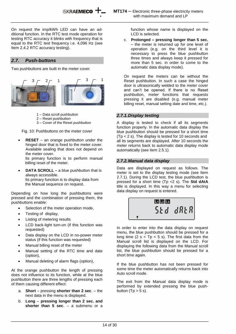
Two pushbuttons are built in the meter cover.
.
1 – Data scroll pushbutton 2 – Reset pushbutton 3 – Cover of the Reset pushbutton
Fig. 10: Pushbuttons on the meter cover
RESET – an orange pushbutton under the hinged door that is fixed to the meter cover. Available sealing that does not depend on the meter cover. Its primary function is to perform manual billing reset of the meter.
DATA SCROLL – a blue pushbutton that is always accessible. Its primary function is to display data from the Manual sequence on request.
Depending on how long the pushbuttons were pressed and the combination of pressing them, the pushbuttons enable:
Selection of the meter operation mode,
Testing of display,
Listing of metering results
LCD back-light turn-on (if this function was requested)
Data display on the LCD in no-power meter status (if this function was requested)
Manual billing reset of the meter
Manual setting of the RTC time and date (option),
Manual deleting of alarm flags (option), At the orange pushbutton the length of pressing does not influence to its function, while at the blue pushbutton there are three lengths of pressing each of them causing different effect:
a. Short – pressing shorter than 2 sec. – the next data in the menu is displayed.
b. Long – pressing longer than 2 sec. and shorter than 5 sec. – a submenu or a
function whose name is displayed on the LCD is selected.
c. Prolonged – pressing longer than 5 sec. – the meter is returned up for one level of operation (e.g. on the third level it is necessary to press the blue pushbutton three times and always keep it pressed for more than 5 sec. in order to come to the automatic data display mode).
On request the meters can be without the Reset pushbutton. In such a case the hinged door is ultrasonically welded to the meter cover and can’t be opened. If there is no Reset pushbutton, meter functions that requests pressing it are disabled (e.g. manual meter billing reset, manual setting date and time, etc.).
2.7.1. Display testing
A display is tested to check if all its segments function properly. In the automatic data display the blue pushbutton should be pressed for a short time (Tp < 2 s). The display is tested for 10 seconds and all its segments are displayed. After 10 seconds the meter returns back to automatic data display mode automatically (see item 2.5.1).
2.7.2. Manual data display
Data are displayed on request as follows. The meter is set to the display testing mode (see Item 2.7.1). During the LCD test, the blue pushbutton is pressed for a short time (Tp <2 s). The Std dAtA title is displayed. In this way a menu for selecting data display on request is entered.
In order to enter into the data display on request menu, the blue pushbutton should be pressed for a long time (2 s < Tp < 5 s). The first data from the Manual scroll list is displayed on the LCD. For displaying the following data from the Manual scroll list, the blue pushbutton should be pressed for a short time again. If the blue pushbutton has not been pressed for some time the meter automatically returns back into Auto scroll mode.
The exit from the Manual data display mode is performed by extended pressing the blue push-button (Tp > 5 s).
3 2 1 3 1
15 of 30
MT174 ─ Electronic three-phase electricity meters
with maximum demand and LP
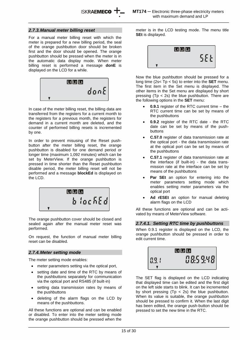
2.7.3. Manual meter billing reset
For a manual meter billing reset with which the meter is prepared for a new billing period, the seal of the orange pushbutton door should be broken first and the door should be opened. The orange pushbutton should be pressed when the meter is in the automatic data display mode. When meter billing reset is performed a message donE is displayed on the LCD for a while.
In case of the meter billing reset, the billing data are transferred from the registers for a current month to the registers for a previous month, the registers for demand in a current month are deleted, and the counter of performed billing resets is incremented by one.
In order to prevent misusing of the Reset push-button after the meter billing reset, the orange pushbutton is disabled for one demand period or longer time (maximum 1,092 minutes) which can be set by MeterView. If the orange pushbutton is pressed in time shorter than the Reset pushbutton disable period, the meter billing reset will not be performed and a message blockEd is displayed on the LCD.
The orange pushbutton cover should be closed and sealed again after the manual meter reset was performed.
On request, the function of manual meter billing reset can be disabled.
2.7.4. Meter setting mode
The meter setting mode enables:
meter parameters setting via the optical port,
setting date and time of the RTC by means of the pushbuttons separately for communication via the optical port and RS485 (if built-in)
setting data transmission rates by means of the pushbuttons
deleting of the alarm flags on the LCD by means of the pushbuttons.
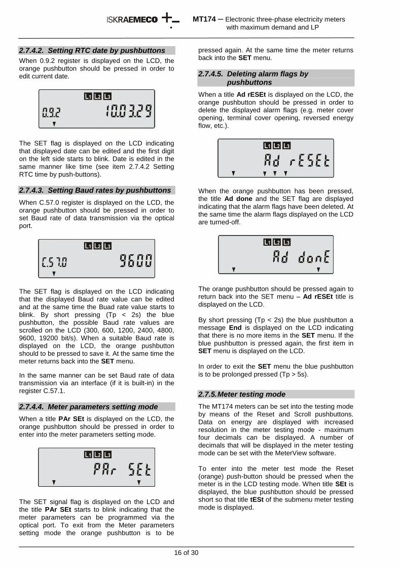
All these functions are optional and can be enabled or disabled. To enter into the meter setting mode the orange pushbutton should be pressed when the
meter is in the LCD testing mode. The menu title SEt is displayed.
Now the blue pushbutton should be pressed for a long time (2s< Tp < 5s) to enter into the SET menu. The first item in the Set menu is displayed. The other items in the Set menu are displayed by short pressing (Tp < 2s) the blue pushbutton. There are the following options in the SET menu:
0.9.1 register of the RTC current time – the RTC current time can be set by means of the pushbuttons
0.9.2 register of the RTC date - the RTC date can be set by means of the push-buttons
C.57.0 register of data transmission rate at the optical port - the data transmission rate at the optical port can be set by means of the pushbuttons
C.57.1 register of data transmission rate at the interface (if built-in) - the data trans-mission rate at the interface can be set by means of the pushbuttons
Par SEt an option for entering into the meter parameters setting mode which enables setting meter parameters via the optical port
Ad rESEt an option for manual deleting alarm flags on the LCD
All these functions are optional and can be acti-vated by means of MeterView software.
2.7.4.1. Setting RTC time by pushbuttons
When 0.9.1 register is displayed on the LCD, the orange pushbutton should be pressed in order to edit current time.
The SET flag is displayed on the LCD indicating that displayed time can be edited and the first digit on the left side starts to blink. It can be incremented by short pressing (Tp < 2s) the blue pushbutton. When its value is suitable, the orange pushbutton should be pressed to confirm it. When the last digit has been edited, the orange push-button should be pressed to set the new time in the RTC.
16 of 30
MT174 ─ Electronic three-phase electricity meters
with maximum demand and LP
2.7.4.2. Setting RTC date by pushbuttons
When 0.9.2 register is displayed on the LCD, the orange pushbutton should be pressed in order to edit current date.
The SET flag is displayed on the LCD indicating that displayed date can be edited and the first digit on the left side starts to blink. Date is edited in the same manner like time (see item 2.7.4.2 Setting RTC time by push-buttons).
2.7.4.3. Setting Baud rates by pushbuttons
When C.57.0 register is displayed on the LCD, the orange pushbutton should be pressed in order to set Baud rate of data transmission via the optical port.
The SET flag is displayed on the LCD indicating that the displayed Baud rate value can be edited and at the same time the Buad rate value starts to blink. By short pressing (Tp < 2s) the blue pushbutton, the possible Baud rate values are scrolled on the LCD (300, 600, 1200, 2400, 4800, 9600, 19200 bit/s). When a suitable Baud rate is displayed on the LCD, the orange pushbutton should to be pressed to save it. At the same time the meter returns back into the SET menu.
In the same manner can be set Baud rate of data transmission via an interface (if it is built-in) in the register C.57.1.
2.7.4.4. Meter parameters setting mode
When a title PAr SEt is displayed on the LCD, the orange pushbutton should be pressed in order to enter into the meter parameters setting mode.
The SET signal flag is displayed on the LCD and the title PAr SEt starts to blink indicating that the meter parameters can be programmed via the optical port. To exit from the Meter parameters setting mode the orange pushbutton is to be
pressed again. At the same time the meter returns back into the SET menu.
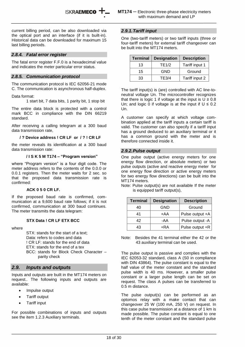
2.7.4.5. Deleting alarm flags by pushbuttons
When a title Ad rESEt is displayed on the LCD, the orange pushbutton should be pressed in order to delete the displayed alarm flags (e.g. meter cover opening, terminal cover opening, reversed energy flow, etc.).
When the orange pushbutton has been pressed, the title Ad done and the SET flag are displayed indicating that the alarm flags have been deleted. At the same time the alarm flags displayed on the LCD are turned-off.
The orange pushbutton should be pressed again to return back into the SET menu – Ad rESEt title is displayed on the LCD. By short pressing (Tp < 2s) the blue pushbutton a message End is displayed on the LCD indicating that there is no more items in the SET menu. If the blue pushbutton is pressed again, the first item in SET menu is displayed on the LCD. In order to exit the SET menu the blue pushbutton is to be prolonged pressed (Tp > 5s).
2.7.5. Meter testing mode
The MT174 meters can be set into the testing mode by means of the Reset and Scroll pushbuttons. Data on energy are displayed with increased resolution in the meter testing mode - maximum four decimals can be displayed. A number of decimals that will be displayed in the meter testing mode can be set with the MeterView software. To enter into the meter test mode the Reset (orange) push-button should be pressed when the meter is in the LCD testing mode. When title SEt is displayed, the blue pushbutton should be pressed short so that title tESt of the submenu meter testing mode is displayed.
17 of 30
MT174 ─ Electronic three-phase electricity meters
with maximum demand and LP
The blue pushbutton should be pressed long (2s< Tp < 5s) to display energy data with increased resolution.
To return back into the standard energy data resolution display mode one must:
send an appropriate formatted command to the meter via its optical port
prolonged pressing (Tp > 5s) the blue push-button
disconnect the meter from phase voltages
2.8. Communication channels
The meters can be equipped with the following communication channels:
Optical interface (always built-in)
RS485 (on request)
Built-in communication channels enable:
Billing data readout
Load-profiles readout
Log-book registers readout
Meter parameters readout
Meter parameters setting
Communication with the meter in progress is indicated on the LCD by the DRO signal flag.
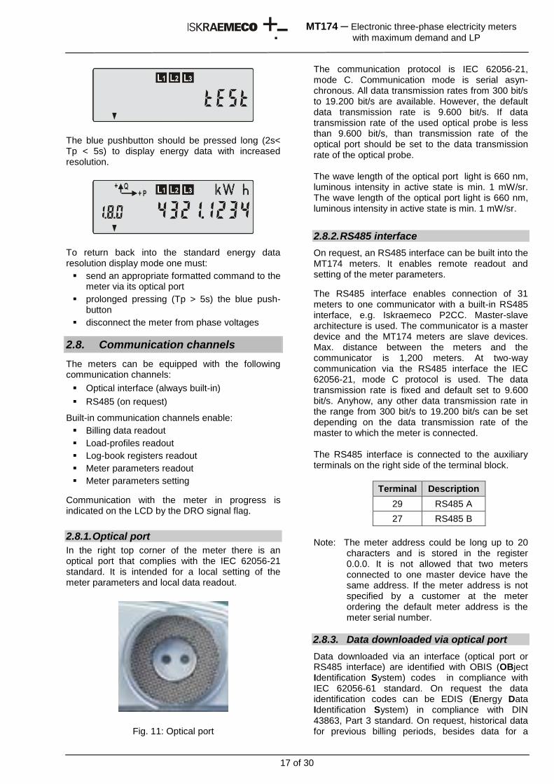
2.8.1. Optical port
In the right top corner of the meter there is an optical port that complies with the IEC 62056-21 standard. It is intended for a local setting of the meter parameters and local data readout.
Fig. 11: Optical port
The communication protocol is IEC 62056-21, mode C. Communication mode is serial asyn-chronous. All data transmission rates from 300 bit/s to 19.200 bit/s are available. However, the default data transmission rate is 9.600 bit/s. If data transmission rate of the used optical probe is less than 9.600 bit/s, than transmission rate of the optical port should be set to the data transmission rate of the optical probe. The wave length of the optical port light is 660 nm, luminous intensity in active state is min. 1 mW/sr. The wave length of the optical port light is 660 nm, luminous intensity in active state is min. 1 mW/sr.
2.8.2. RS485 interface
On request, an RS485 interface can be built into the MT174 meters. It enables remote readout and setting of the meter parameters.
The RS485 interface enables connection of 31 meters to one communicator with a built-in RS485 interface, e.g. Iskraemeco P2CC. Master-slave architecture is used. The communicator is a master device and the MT174 meters are slave devices. Max. distance between the meters and the communicator is 1,200 meters. At two-way communication via the RS485 interface the IEC 62056-21, mode C protocol is used. The data transmission rate is fixed and default set to 9.600 bit/s. Anyhow, any other data transmission rate in the range from 300 bit/s to 19.200 bit/s can be set depending on the data transmission rate of the master to which the meter is connected. The RS485 interface is connected to the auxiliary terminals on the right side of the terminal block.
Terminal Description
29 RS485 A
27 RS485 B
Note: The meter address could be long up to 20
characters and is stored in the register 0.0.0. It is not allowed that two meters connected to one master device have the same address. If the meter address is not specified by a customer at the meter ordering the default meter address is the meter serial number.
2.8.3. Data downloaded via optical port
Data downloaded via an interface (optical port or RS485 interface) are identified with OBIS (OBject Identification System) codes in compliance with IEC 62056-61 standard. On request the data identification codes can be EDIS (Energy Data Identification System) in compliance with DIN 43863, Part 3 standard. On request, historical data for previous billing periods, besides data for a
18 of 30
MT174 ─ Electronic three-phase electricity meters
with maximum demand and LP
current billing period, can be also downloaded via the optical port and an interface (if it is built-in). Historical data can be downloaded for maximum 15 last billing periods.
2.8.4. Fatal error register
The fatal error register F.F.0 is a hexadecimal value and indicates the meter particular error status.
2.8.5. Communication protocol
The communication protocol is IEC 62056-21 mode C. The communication is asynchronous half-duplex.
Data format: 1 start bit, 7 data bits, 1 parity bit, 1 stop bit
The entire data block is protected with a control mark BCC in compliance with the DIN 66219 standard.
After receiving a calling telegram at a 300 baud data transmission rate,
/ ? Device address ! CR LF or / ? ! CR LF
the meter reveals its identification at a 300 baud data transmission rate:
/ I S K 5 M T174 – “Program version”
where “Program version” is a four digit code. The meter address refers to the contents of the 0.0.0 or 0.0.1 registers. Then the meter waits for 2 sec. so that the proposed data transmission rate is confirmed:
ACK 0 5 0 CR LF.
If the proposed baud rate is confirmed, com-munication at a 9,600 baud rate follows; if it is not confirmed, communication at 300 baud continues. The meter transmits the data telegram:
STX Data ! CR LF ETX BCC
where STX: stands for the start of a text; Data: refers to codes and data
! CR LF: stands for the end of data ETX: stands for the end of a tex
BCC: stands for Block Check Character – parity check
2.9. Inputs and outputs
Inputs and outputs are built in the MT174 meters on request.. The following inputs and outputs are available:
Impulse output
Tariff output
Tariff input For possible combinations of inputs and outputs see the item 1.2.3 Auxiliary terminals.
2.9.1. Tariff input
One (two-tariff meters) or two tariff inputs (three or four-tariff meters) for external tariff changeover can be built into the MT174 meters.
Terminal Designation Description
13 TE1/2 Tariff input 1
15 GND Ground
33 TE3/4 Tariff input 2
The tariff input(s) is (are) controlled with AC line-to-neutral voltage Un. The microcontroller recognizes that there is logic 1 if voltage at the input is U ≥ 0.8 Un; and logic 0 if voltage is at the input if U ≤ 0.2 Un.
A customer can specify at which voltage com-bination applied at the tariff inputs a certain tariff is valid. The customer can also specify if a tariff input has a ground deduced to an auxiliary terminal or it has a common ground with the meter and is therefore connected inside it.
2.9.2. Pulse output
One pulse output (active energy meters for one energy flow direction, or absolute meters) or two pulse outputs (active and reactive energy meter for one energy flow direction or active energy meters for two energy flow directions) can be built into the MT174 meters. Note: Pulse output(s) are not available If the meter
is equipped tariff output(s),
Terminal Designation Description
40 GND Ground
41 +AA Pulse output +A
42 -AA Pulse output -A
43 +RA Pulse output +R
Note: Besides the 41 terminal either the 42 or the
43 auxiliary terminal can be used.
The pulse output is passive and complies with the IEC 62053-32 standard, class A (S0 in compliance with DIN 43864). The pulse constant is equal to the half value of the meter constant and the standard pulse width is 40 ms. However, a smaller pulse constant or a larger pulse length can be set on request. The class A pulses can be transferred to 0.5 m distance.
The pulse output(s) can be performed as an optomos relay with a make contact that can changeover 25 W (100 mA, 250 V) on request. In this case pulse transmission at a distance of 1 km is made possible. The pulse constant is equal to one tenth of the meter constant and the standard pulse
19 of 30
MT174 ─ Electronic three-phase electricity meters
with maximum demand and LP
width is 100 ms. However, a smaller pulse constant or other pulse length can be set on request.
Note: Pulse output(s) are not available If the meter is equipped tariff output(s).
2.9.3. Tariff output
One or two tariff outputs can be built into the MT174 meters for controlling an external device by a tariff program that is stored in the meter instead of pulse output(s).
Terminal Designation Description
61 TA1/2 Tariff output 1
65 GND Ground
63 TA3/4 Tariff output 2
The tariff output is performed as an optomos relay with a make contact that can switchover 25 W (100 mA, 250 V).
Note: Tariff output(s) are not available if the meter is equipped pulse output(s).
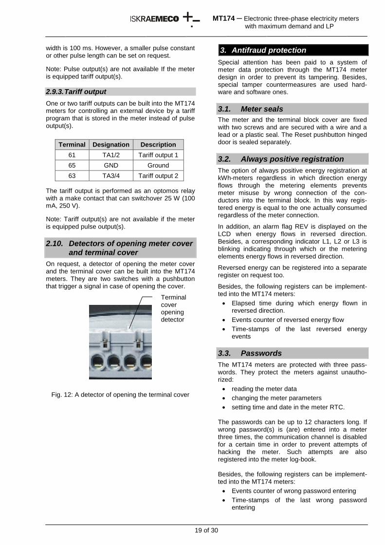
2.10. Detectors of opening meter cover and terminal cover
On request, a detector of opening the meter cover and the terminal cover can be built into the MT174 meters. They are two switches with a pushbutton that trigger a signal in case of opening the cover.
Fig. 12: A detector of opening the terminal cover
3. Antifraud protection
Special attention has been paid to a system of meter data protection through the MT174 meter design in order to prevent its tampering. Besides, special tamper countermeasures are used hard-ware and software ones.
3.1. Meter seals
The meter and the terminal block cover are fixed with two screws and are secured with a wire and a lead or a plastic seal. The Reset pushbutton hinged door is sealed separately.
3.2. Always positive registration
The option of always positive energy registration at kWh-meters regardless in which direction energy flows through the metering elements prevents meter misuse by wrong connection of the con-ductors into the terminal block. In this way regis-tered energy is equal to the one actually consumed regardless of the meter connection.
In addition, an alarm flag REV is displayed on the LCD when energy flows in reversed direction. Besides, a corresponding indicator L1, L2 or L3 is blinking indicating through which or the metering elements energy flows in reversed direction.
Reversed energy can be registered into a separate register on request too.
Besides, the following registers can be implement-ted into the MT174 meters:
Elapsed time during which energy flown in reversed direction.
Events counter of reversed energy flow
Time-stamps of the last reversed energy events
3.3. Passwords
The MT174 meters are protected with three pass-words. They protect the meters against unautho-rized:
reading the meter data
changing the meter parameters
setting time and date in the meter RTC. The passwords can be up to 12 characters long. If wrong password(s) is (are) entered into a meter three times, the communication channel is disabled for a certain time in order to prevent attempts of hacking the meter. Such attempts are also registered into the meter log-book. Besides, the following registers can be implement-ted into the MT174 meters:
Events counter of wrong password entering
Time-stamps of the last wrong password entering
Terminal cover opening detector
20 of 30
MT174 ─ Electronic three-phase electricity meters
with maximum demand and LP
3.4. Parameters change protected with a sealed pushbutton
Besides protection with a password the meter parameters change can be protected with the Reset pushbutton which is sealed. In such a case the Reset pushbutton seal should be broken and the Reset pushbutton be pressed before the meter parameters can be changed.
3.5. Cover(s) opening detector(s)
On request, a detector of the meter and/or the terminal cover opening can be built into the meter. The event is registered in the log-book together with its time-stamp (date and time) and the correspond-ding flag is displayed in the LCD.
Besides, the following registers can be implement-ted into the MT174 meters:
Fraud energy register (see item 3.10 Registers of fraud energy)
Events counter of a cover opening
Time-stamps of the last reversed cover opening events
3.6. Detector of external magnetic field
On request, a detector of an external magnetic field can be built into the meter. If an external magnetic field is detected, this event is registered in the log -book together with its time stamp (date and time) and the corresponding flag is displayed in the LCD.
Consumed energy during meter tampering with a permanent magnet can be registered into a separate register on request too.
Besides, the following registers can be implement-ted into the MT174 meters:
Fraud energy register (see item 3.10 Registers of fraud energy)
Elapsed time during which the meter was exposed to a permanent magnet field (if a magnet field detector is built-in).
Events counter of a meter tampering with a permanent magnet
Time-stamps of the last meter tampering with a permanent magnet events
3.7. Fourth metering element
On request, a fourth metering element can be built into the MT174 meters. It measure current flowing through the neutral circuit. The microcontroller cal-culates a vector sum of the currents flowing through the lines and compare it with a current flowing through the neutral circuit. If this difference is higher than 6%, this event is registered into the log-book together with its time stamp (date and time) and the corresponding flag is displayed in the LCD.
Besides, the following registers can be implement-ted into the MT174 meters:
Fraud energy register (see item 3.10 Registers of fraud energy)
Elapsed time during which current through the neutral do not match to the vector sum of the current through the lines.
Events counter of the meter tampering via its neutral
Time-stamps of the last meter tampering via its neutral
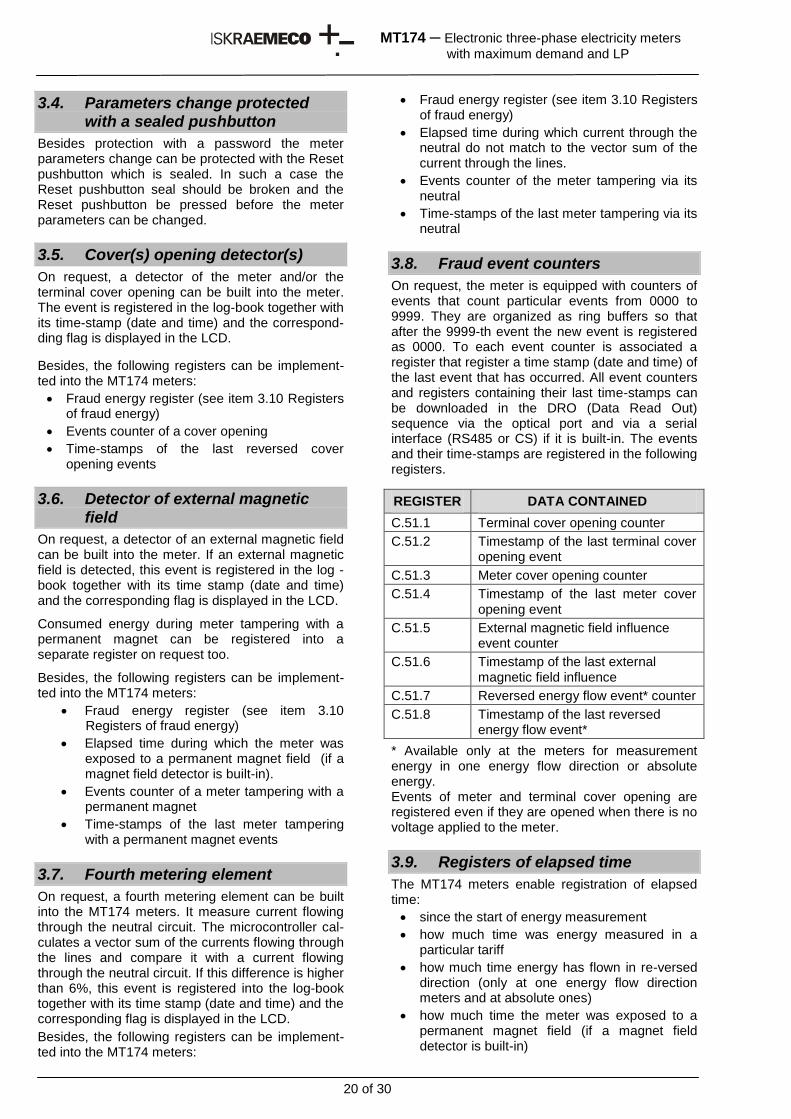
3.8. Fraud event counters
On request, the meter is equipped with counters of events that count particular events from 0000 to 9999. They are organized as ring buffers so that after the 9999-th event the new event is registered as 0000. To each event counter is associated a register that register a time stamp (date and time) of the last event that has occurred. All event counters and registers containing their last time-stamps can be downloaded in the DRO (Data Read Out) sequence via the optical port and via a serial interface (RS485 or CS) if it is built-in. The events and their time-stamps are registered in the following registers.
REGISTER DATA CONTAINED
C.51.1 Terminal cover opening counter
C.51.2 Timestamp of the last terminal cover opening event
C.51.3 Meter cover opening counter
C.51.4 Timestamp of the last meter cover opening event
C.51.5 External magnetic field influence event counter
C.51.6 Timestamp of the last external magnetic field influence
C.51.7 Reversed energy flow event* counter
C.51.8 Timestamp of the last reversed energy flow event*
* Available only at the meters for measurement energy in one energy flow direction or absolute energy. Events of meter and terminal cover opening are registered even if they are opened when there is no voltage applied to the meter.
3.9. Registers of elapsed time
The MT174 meters enable registration of elapsed time:
since the start of energy measurement
how much time was energy measured in a particular tariff
how much time energy has flown in re-versed direction (only at one energy flow direction meters and at absolute ones)
how much time the meter was exposed to a permanent magnet field (if a magnet field detector is built-in)
21 of 30
MT174 ─ Electronic three-phase electricity meters
with maximum demand and LP
how much time current flowing through the neutral does not match to the vector sum of currents flowing through the lines (if the fourth metering element is built-in)
Besides the meters have a counter which registers elapsed time during which no voltage has been applied to the meter.
Elapsed times can be expressed either in hours – in such a case five digits are available or expressed in a form of YYMMDDhhmmss where: YY – years, MM – months, DD – days, hh – hours mm – minutes, ss - seconds
3.10. Registers of fraud energy
The MT174 meters have five registers in which energy is separately registered during the meter tampering besides energy registered in the cor-responding registers. The fraud energy registers are available for the following tamper attempts:
reversed energy flow direction (only at one energy flow direction meters and at absolute ones)
permanent magnet field exposure (if a magnet field detector is built-in)
current flowing through the neutral does not match to the vector sum of currents flowing through the lines (if the fourth metering element is built-in)
energy registered since the meter and/or terminal cover has been opened
Besides, time how long a particular fraud has lasted is registered in the corresponding register of elapsed time (see item 10. Tamper registers (counters and time-stamps) in the Appendix: EDIS codes, data stored in registers, sequences, historical values)
3.11. Log-books
All events are registered also in the log-books (see item 2.3.2) together with their time stamps (date and time of the event occurence).
3.12. SEP2 MeterView software
SEP2 MeterView software for meter managing is available on request instead of the standard Meter-View software. The SEP2 MeterVew enables:
Logging of a user to the SEP2 MeterView software by entering its user name and its password
Multi level authorisation (meter reading, time and date setting, changing meter parameters, deleting energy registers)
Data base keeping data who, when and what has done with a particular meter.
4. Tools for meter managing
The following tools are used for managing the MT174 meters:
For service meter programming and local data downloading:
1. MeterView or alternatively SEP2 MeterView (Iskraemeco software)
2. Optical Probe
3. PC: a desk-top or a lap-top with operating system Windows XP or later Windows version
The tool is intended for the operators who service or reprogram the meters in the laboratory or in the field.
For local data downloading and meters programming in the field
1. MeterRead (Iskraemeco software) for all type of palm-top PCs operating in the Windows Mobile operating system
2. Optical probe
3. Palm-top PC with Windows Mobile
The tool is intended for personal who read-out the meters in the field.
5. Meter maintenance
The meter is designed and manufactured in such a way that no maintenance is required in the entire meter lifetime. Measuring stability assures that no recalibration is required. If a battery is built into the meter, its capacity is sufficient to backup all meter functions for its entire lifetime.
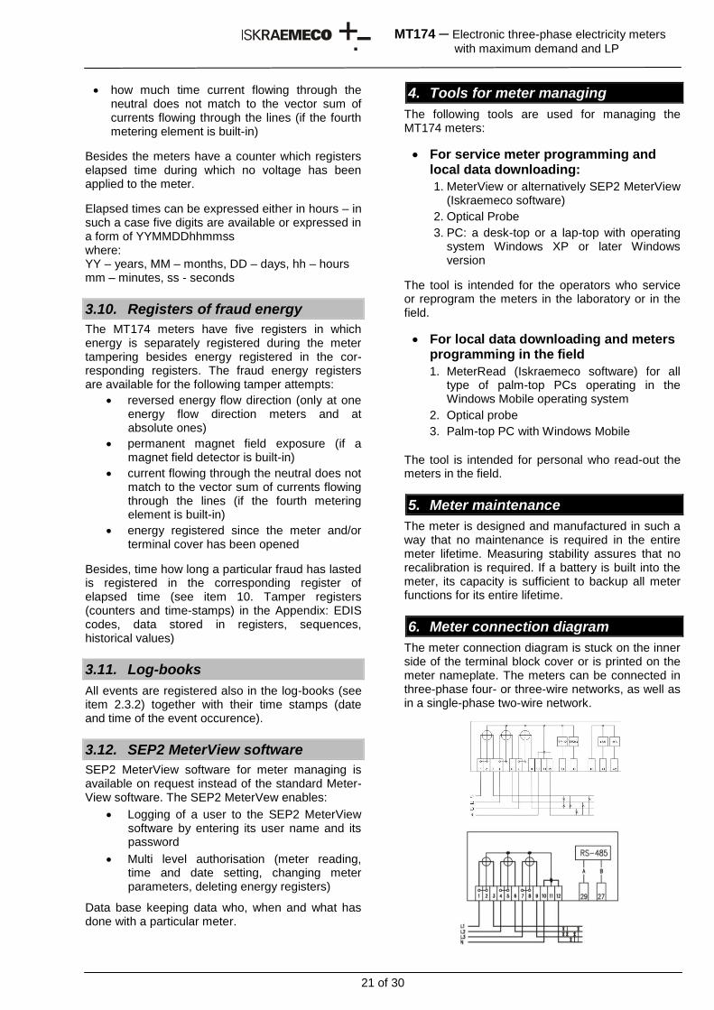
6. Meter connection diagram
The meter connection diagram is stuck on the inner side of the terminal block cover or is printed on the meter nameplate. The meters can be connected in three-phase four- or three-wire networks, as well as in a single-phase two-wire network.
22 of 30
MT174 ─ Electronic three-phase electricity meters
with maximum demand and LP
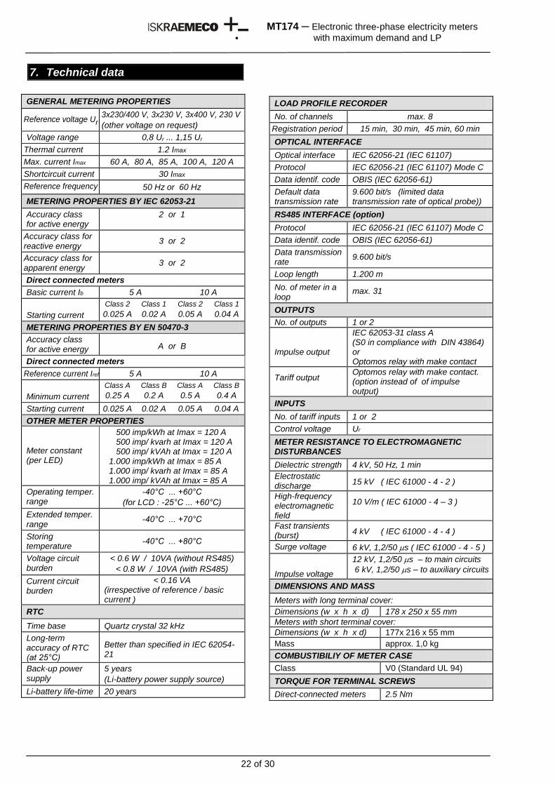
7. Technical data
GENERAL METERING PROPERTIES
Reference voltage Ur 3x230/400 V, 3x230 V, 3x400 V, 230 V
(other voltage on request)
Voltage range 0,8 Ur ... 1,15 Ur
Thermal current 1.2 Imax
Max. current Imax 60 A, 80 A, 85 A, 100 A, 120 A
Shortcircuit current 30 Imax
Reference frequency 50 Hz or 60 Hz
METERING PROPERTIES BY IEC 62053-21
Accuracy class for active energy
2 or 1
Accuracy class for reactive energy
3 or 2
Accuracy class for apparent energy
3 or 2
Direct connected meters
Basic current Ib 5 A 10 A
Starting current
Class 2
0.025 A
Class 1
0.02 A
Class 2
0.05 A
Class 1
0.04 A
METERING PROPERTIES BY EN 50470-3
Accuracy class for active energy A or B
Direct connected meters
Reference current Iref 5 A 10 A
Minimum current
Class A
0.25 A
Class B
0.2 A
Class A
0.5 A
Class B
0.4 A
Starting current 0.025 A 0.02 A 0.05 A 0.04 A
OTHER METER PROPERTIES
Meter constant (per LED)
500 imp/kWh at Imax = 120 A 500 imp/ kvarh at Imax = 120 A 500 imp/ kVAh at Imax = 120 A 1.000 imp/kWh at Imax = 85 A 1.000 imp/ kvarh at Imax = 85 A 1.000 imp/ kVAh at Imax = 85 A
Operating temper. range
-40°C ... +60°C
(for LCD : -25°C ... +60°C)
Extended temper. range
-40°C ... +70°C
Storing temperature
-40°C ... +80°C
Voltage circuit burden
< 0.6 W / 10VA (without RS485)
< 0.8 W / 10VA (with RS485)
Current circuit burden
< 0.16 VA (irrespective of reference / basic current )
RTC
Time base Quartz crystal 32 kHz
Long-term accuracy of RTC (at 25°C)
Better than specified in IEC 62054-21
Back-up power supply
5 years
(Li-battery power supply source)
Li-battery life-time 20 years
LOAD PROFILE RECORDER
No. of channels max. 8
Registration period 15 min, 30 min, 45 min, 60 min
OPTICAL INTERFACE
Optical interface IEC 62056-21 (IEC 61107)
Protocol IEC 62056-21 (IEC 61107) Mode C
Data identif. code OBIS (IEC 62056-61)
Default data transmission rate
9.600 bit/s (limited data transmission rate of optical probe))
RS485 INTERFACE (option)
Protocol IEC 62056-21 (IEC 61107) Mode C
Data identif. code OBIS (IEC 62056-61)
Data transmission rate
9.600 bit/s
Loop length 1.200 m
No. of meter in a loop
max. 31
OUTPUTS
No. of outputs 1 or 2
Impulse output
IEC 62053-31 class A (S0 in compliance with DIN 43864) or Optomos relay with make contact
Tariff output Optomos relay with make contact. (option instead of of impulse output)
INPUTS
No. of tariff inputs 1 or 2
Control voltage Ur
METER RESISTANCE TO ELECTROMAGNETIC DISTURBANCES
Dielectric strength 4 kV, 50 Hz, 1 min
Electrostatic discharge
15 kV ( IEC 61000 - 4 - 2 )
High-frequency electromagnetic field
10 V/m ( IEC 61000 - 4 – 3 )
Fast transients (burst)
4 kV ( IEC 61000 - 4 - 4 )
Surge voltage 6 kV, 1,2/50 s ( IEC 61000 - 4 - 5 )
Impulse voltage
12 kV, 1,2/50 s – to main circuits
6 kV, 1,2/50 s – to auxiliary circuits
DIMENSIONS AND MASS
Meters with long terminal cover:
Dimensions (w x h x d) 178 x 250 x 55 mm
Meters with short terminal cover:
Dimensions (w x h x d) 177x 216 x 55 mm
Mass approx. 1,0 kg
COMBUSTIBILIY OF METER CASE
Class V0 (Standard UL 94)
TORQUE FOR TERMINAL SCREWS
Direct-connected meters 2.5 Nm
23 of 30
MT174 ─ Electronic three-phase electricity meters
with maximum demand and LP
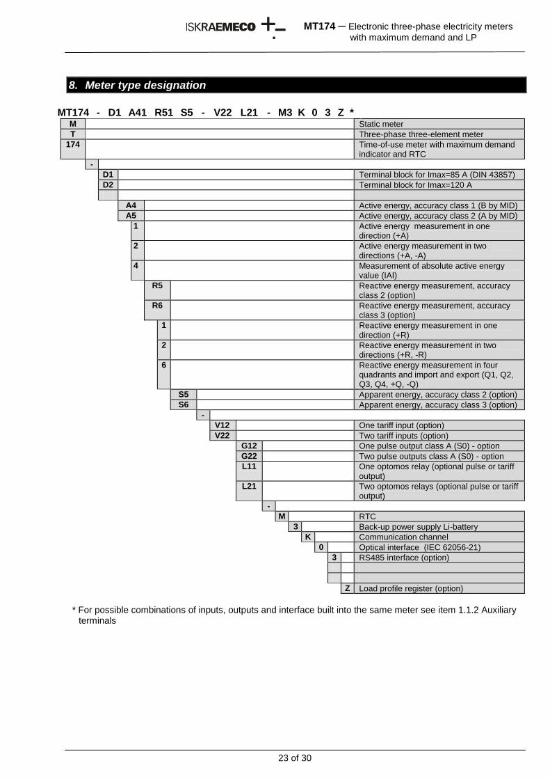
8. Meter type designation
MT174 - D1 A41 R51 S5 - V22 L21 - M3 K 0 3 Z * M Static meter
T Three-phase three-element meter
174 Time-of-use meter with maximum demand indicator and RTC
-
D1 Terminal block for Imax=85 A (DIN 43857)
D2 Terminal block for Imax=120 A
A4 Active energy, accuracy class 1 (B by MID)
A5 Active energy, accuracy class 2 (A by MID)
1 Active energy measurement in one direction (+A)
2 Active energy measurement in two directions (+A, -A)
4 Measurement of absolute active energy value (IAI)
R5 Reactive energy measurement, accuracy class 2 (option)
R6 Reactive energy measurement, accuracy class 3 (option)
1 Reactive energy measurement in one direction (+R)
2 Reactive energy measurement in two directions (+R, -R)
6 Reactive energy measurement in four quadrants and import and export (Q1, Q2, Q3, Q4, +Q, -Q)
S5 Apparent energy, accuracy class 2 (option)
S6 Apparent energy, accuracy class 3 (option)
-
V12 One tariff input (option)
V22 Two tariff inputs (option)
G12 One pulse output class A (S0) - option
G22 Two pulse outputs class A (S0) - option
L11 One optomos relay (optional pulse or tariff output)
L21 Two optomos relays (optional pulse or tariff output)
-
M RTC
3 Back-up power supply Li-battery
K Communication channel
0 Optical interface (IEC 62056-21)
3 RS485 interface (option)
Z Load profile register (option)
* For possible combinations of inputs, outputs and interface built into the same meter see item 1.1.2 Auxiliary
terminals
24 of 30
MT174 ─ Electronic three-phase electricity meters
with maximum demand and LP
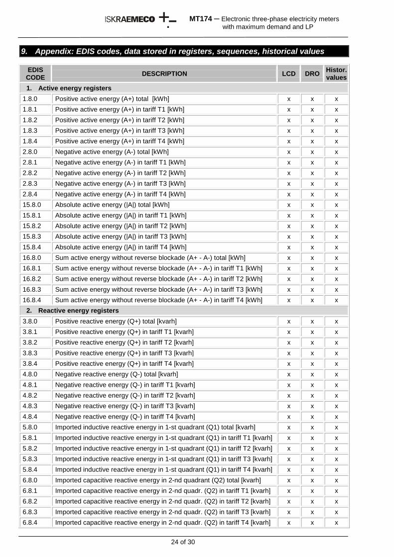
9. Appendix: EDIS codes, data stored in registers, sequences, historical values
EDIS CODE
DESCRIPTION LCD DRO Histor. values
1. Active energy registers
1.8.0 Positive active energy (A+) total [kWh] x x x
1.8.1 Positive active energy (A+) in tariff T1 [kWh] x x x
1.8.2 Positive active energy (A+) in tariff T2 [kWh] x x x
1.8.3 Positive active energy (A+) in tariff T3 [kWh] x x x
1.8.4 Positive active energy (A+) in tariff T4 [kWh] x x x
2.8.0 Negative active energy (A-) total [kWh] x x x
2.8.1 Negative active energy (A-) in tariff T1 [kWh] x x x
2.8.2 Negative active energy (A-) in tariff T2 [kWh] x x x
2.8.3 Negative active energy (A-) in tariff T3 [kWh] x x x
2.8.4 Negative active energy (A-) in tariff T4 [kWh] x x x
15.8.0 Absolute active energy (|A|) total [kWh] x x x
15.8.1 Absolute active energy (|A|) in tariff T1 [kWh] x x x
15.8.2 Absolute active energy (|A|) in tariff T2 [kWh] x x x
15.8.3 Absolute active energy (|A|) in tariff T3 [kWh] x x x
15.8.4 Absolute active energy (|A|) in tariff T4 [kWh] x x x
16.8.0 Sum active energy without reverse blockade (A+ - A-) total [kWh] x x x
16.8.1 Sum active energy without reverse blockade (A+ - A-) in tariff T1 [kWh] x x x
16.8.2 Sum active energy without reverse blockade (A+ - A-) in tariff T2 [kWh] x x x
16.8.3 Sum active energy without reverse blockade (A+ - A-) in tariff T3 [kWh] x x x
16.8.4 Sum active energy without reverse blockade (A+ - A-) in tariff T4 [kWh] x x x
2. Reactive energy registers
3.8.0 Positive reactive energy (Q+) total [kvarh] x x x
3.8.1 Positive reactive energy (Q+) in tariff T1 [kvarh] x x x
3.8.2 Positive reactive energy (Q+) in tariff T2 [kvarh] x x x
3.8.3 Positive reactive energy (Q+) in tariff T3 [kvarh] x x x
3.8.4 Positive reactive energy (Q+) in tariff T4 [kvarh] x x x
4.8.0 Negative reactive energy (Q-) total [kvarh] x x x
4.8.1 Negative reactive energy (Q-) in tariff T1 [kvarh] x x x
4.8.2 Negative reactive energy (Q-) in tariff T2 [kvarh] x x x
4.8.3 Negative reactive energy (Q-) in tariff T3 [kvarh] x x x
4.8.4 Negative reactive energy (Q-) in tariff T4 [kvarh] x x x
5.8.0 Imported inductive reactive energy in 1-st quadrant (Q1) total [kvarh] x x x
5.8.1 Imported inductive reactive energy in 1-st quadrant (Q1) in tariff T1 [kvarh] x x x
5.8.2 Imported inductive reactive energy in 1-st quadrant (Q1) in tariff T2 [kvarh] x x x
5.8.3 Imported inductive reactive energy in 1-st quadrant (Q1) in tariff T3 [kvarh] x x x
5.8.4 Imported inductive reactive energy in 1-st quadrant (Q1) in tariff T4 [kvarh] x x x
6.8.0 Imported capacitive reactive energy in 2-nd quadrant (Q2) total [kvarh] x x x
6.8.1 Imported capacitive reactive energy in 2-nd quadr. (Q2) in tariff T1 [kvarh] x x x
6.8.2 Imported capacitive reactive energy in 2-nd quadr. (Q2) in tariff T2 [kvarh] x x x
6.8.3 Imported capacitive reactive energy in 2-nd quadr. (Q2) in tariff T3 [kvarh] x x x
6.8.4 Imported capacitive reactive energy in 2-nd quadr. (Q2) in tariff T4 [kvarh] x x x
25 of 30
MT174 ─ Electronic three-phase electricity meters
with maximum demand and LP
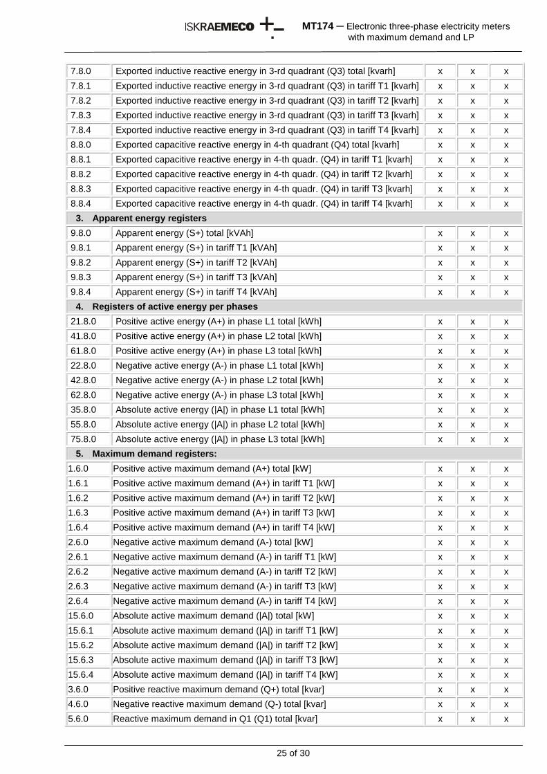
7.8.0 Exported inductive reactive energy in 3-rd quadrant (Q3) total [kvarh] x x x
7.8.1 Exported inductive reactive energy in 3-rd quadrant (Q3) in tariff T1 [kvarh] x x x
7.8.2 Exported inductive reactive energy in 3-rd quadrant (Q3) in tariff T2 [kvarh] x x x
7.8.3 Exported inductive reactive energy in 3-rd quadrant (Q3) in tariff T3 [kvarh] x x x
7.8.4 Exported inductive reactive energy in 3-rd quadrant (Q3) in tariff T4 [kvarh] x x x
8.8.0 Exported capacitive reactive energy in 4-th quadrant (Q4) total [kvarh] x x x
8.8.1 Exported capacitive reactive energy in 4-th quadr. (Q4) in tariff T1 [kvarh] x x x
8.8.2 Exported capacitive reactive energy in 4-th quadr. (Q4) in tariff T2 [kvarh] x x x
8.8.3 Exported capacitive reactive energy in 4-th quadr. (Q4) in tariff T3 [kvarh] x x x
8.8.4 Exported capacitive reactive energy in 4-th quadr. (Q4) in tariff T4 [kvarh] x x x
3. Apparent energy registers
9.8.0 Apparent energy (S+) total [kVAh] x x x
9.8.1 Apparent energy (S+) in tariff T1 [kVAh] x x x
9.8.2 Apparent energy (S+) in tariff T2 [kVAh] x x x
9.8.3 Apparent energy (S+) in tariff T3 [kVAh] x x x
9.8.4 Apparent energy (S+) in tariff T4 [kVAh] x x x
4. Registers of active energy per phases
21.8.0 Positive active energy (A+) in phase L1 total [kWh] x x x
41.8.0 Positive active energy (A+) in phase L2 total [kWh] x x x
61.8.0 Positive active energy (A+) in phase L3 total [kWh] x x x
22.8.0 Negative active energy (A-) in phase L1 total [kWh] x x x
42.8.0 Negative active energy (A-) in phase L2 total [kWh] x x x
62.8.0 Negative active energy (A-) in phase L3 total [kWh] x x x
35.8.0 Absolute active energy (|A|) in phase L1 total [kWh] x x x
55.8.0 Absolute active energy (|A|) in phase L2 total [kWh] x x x
75.8.0 Absolute active energy (|A|) in phase L3 total [kWh] x x x
5. Maximum demand registers:
1.6.0 Positive active maximum demand (A+) total [kW] x x x
1.6.1 Positive active maximum demand (A+) in tariff T1 [kW] x x x
1.6.2 Positive active maximum demand (A+) in tariff T2 [kW] x x x
1.6.3 Positive active maximum demand (A+) in tariff T3 [kW] x x x
1.6.4 Positive active maximum demand (A+) in tariff T4 [kW] x x x
2.6.0 Negative active maximum demand (A-) total [kW] x x x
2.6.1 Negative active maximum demand (A-) in tariff T1 [kW] x x x
2.6.2 Negative active maximum demand (A-) in tariff T2 [kW] x x x
2.6.3 Negative active maximum demand (A-) in tariff T3 [kW] x x x
2.6.4 Negative active maximum demand (A-) in tariff T4 [kW] x x x
15.6.0 Absolute active maximum demand (|A|) total [kW] x x x
15.6.1 Absolute active maximum demand (|A|) in tariff T1 [kW] x x x
15.6.2 Absolute active maximum demand (|A|) in tariff T2 [kW] x x x
15.6.3 Absolute active maximum demand (|A|) in tariff T3 [kW] x x x
15.6.4 Absolute active maximum demand (|A|) in tariff T4 [kW] x x x
3.6.0 Positive reactive maximum demand (Q+) total [kvar] x x x
4.6.0 Negative reactive maximum demand (Q-) total [kvar] x x x
5.6.0 Reactive maximum demand in Q1 (Q1) total [kvar] x x x
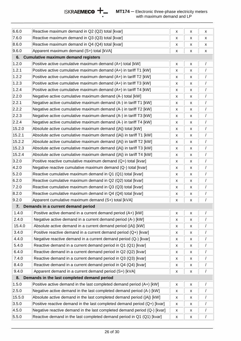
26 of 30
MT174 ─ Electronic three-phase electricity meters
with maximum demand and LP
6.6.0 Reactive maximum demand in Q2 (Q2) total [kvar] x x x
7.6.0 Reactive maximum demand in Q3 (Q3) total [kvar] x x x
8.6.0 Reactive maximum demand in Q4 (Q4) total [kvar] x x x
9.6.0 Apparent maximum demand (S+) total [kVA] x x x
6. Cumulative maximum demand registers
1.2.0 Positive active cumulative maximum demand (A+) total [kW] x x /
1.2.1 Positive active cumulative maximum demand (A+) in tariff T1 [kW] x x /
1.2.2 Positive active cumulative maximum demand (A+) in tariff T2 [kW] x x /
1.2.3 Positive active cumulative maximum demand (A+) in tariff T3 [kW] x x /
1.2.4 Positive active cumulative maximum demand (A+) in tariff T4 [kW] x x /
2.2.0 Negative active cumulative maximum demand (A-) total [kW] x x /
2.2.1 Negative active cumulative maximum demand (A-) in tariff T1 [kW] x x /
2.2.2 Negative active cumulative maximum demand (A-) in tariff T2 [kW] x x /
2.2.3 Negative active cumulative maximum demand (A-) in tariff T3 [kW] x x /
2.2.4 Negative active cumulative maximum demand (A-) in tariff T4 [kW] x x /
15.2.0 Absolute active cumulative maximum demand (|A|) total [kW] x x /
15.2.1 Absolute active cumulative maximum demand (|A|) in tariff T1 [kW] x x /
15.2.2 Absolute active cumulative maximum demand (|A|) in tariff T2 [kW] x x /
15.2.3 Absolute active cumulative maximum demand (|A|) in tariff T3 [kW] x x /
15.2.4 Absolute active cumulative maximum demand (|A|) in tariff T4 [kW] x x /
3.2.0 Positive reactive cumulative maximum demand (Q+) total [kvar] x x /
4.2.0 Negative reactive cumulative maximum demand (Q-) total [kvar] x x /
5.2.0 Reactive cumulative maximum demand in Q1 (Q1) total [kvar] x x /
6.2.0 Reactive cumulative maximum demand in Q2 (Q2) total [kvar] x x /
7.2.0 Reactive cumulative maximum demand in Q3 (Q3) total [kvar] x x /
8.2.0 Reactive cumulative maximum demand in Q4 (Q4) total [kvar] x x /
9.2.0 Apparent cumulative maximum demand (S+) total [kVA] x x /
7. Demands in a current demand period
1.4.0 Positive active demand in a current demand period (A+) [kW] x x /
2.4.0 Negative active demand in a current demand period (A-) [kW] x x /
15.4.0 Absolute active demand in a current demand period (|A|) [kW] x x /
3.4.0 Positive reactive demand in a current demand period (Q+) [kvar] x x /
4.4.0 Negative reactive demand in a current demand period (Q-) [kvar] x x /
5.4.0 Reactive demand in a current demand period in Q1 (Q1) [kvar] x x /
6.4.0 Reactive demand in a current demand period in Q2 (Q2) [kvar] x x /
7.4.0 Reactive demand in a current demand period in Q3 (Q3) [kvar] x x /
8.4.0 Reactive demand in a current demand period in Q4 (Q4) [kvar] x x /
9.4.0 Apparent demand in a current demand period (S+) [kVA] x x /
8. Demands in the last completed demand period
1.5.0 Positive active demand in the last completed demand period (A+) [kW] x x /
2.5.0 Negative active demand in the last completed demand period (A-) [kW] x x /
15.5.0 Absolute active demand in the last completed demand period (|A|) [kW] x x /
3.5.0 Positive reactive demand in the last completed demand period (Q+) [kvar] x x /
4.5.0 Negative reactive demand in the last completed demand period (Q-) [kvar] x x /
5.5.0 Reactive demand in the last completed demand period in Q1 (Q1) [kvar] x x /
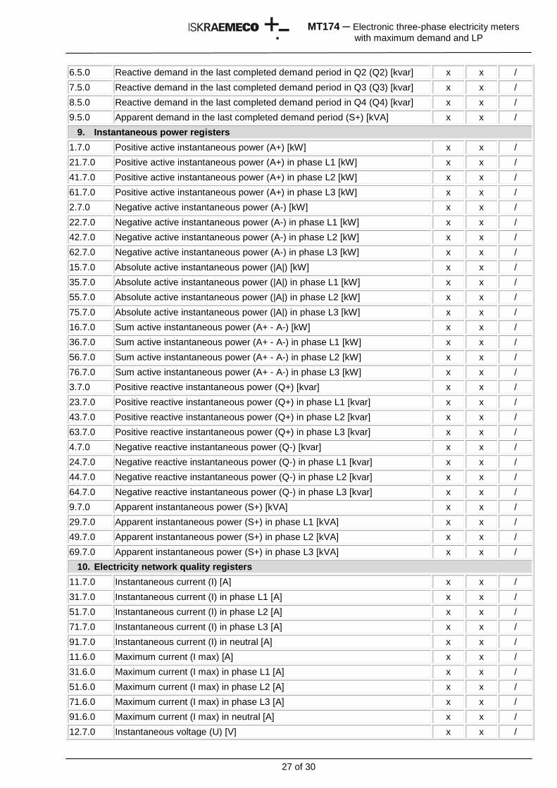
27 of 30
MT174 ─ Electronic three-phase electricity meters
with maximum demand and LP
6.5.0 Reactive demand in the last completed demand period in Q2 (Q2) [kvar] x x /
7.5.0 Reactive demand in the last completed demand period in Q3 (Q3) [kvar] x x /
8.5.0 Reactive demand in the last completed demand period in Q4 (Q4) [kvar] x x /
9.5.0 Apparent demand in the last completed demand period (S+) [kVA] x x /
9. Instantaneous power registers
1.7.0 Positive active instantaneous power (A+) [kW] x x /
21.7.0 Positive active instantaneous power (A+) in phase L1 [kW] x x /
41.7.0 Positive active instantaneous power (A+) in phase L2 [kW] x x /
61.7.0 Positive active instantaneous power (A+) in phase L3 [kW] x x /
2.7.0 Negative active instantaneous power (A-) [kW] x x /
22.7.0 Negative active instantaneous power (A-) in phase L1 [kW] x x /
42.7.0 Negative active instantaneous power (A-) in phase L2 [kW] x x /
62.7.0 Negative active instantaneous power (A-) in phase L3 [kW] x x /
15.7.0 Absolute active instantaneous power (|A|) [kW] x x /
35.7.0 Absolute active instantaneous power (|A|) in phase L1 [kW] x x /
55.7.0 Absolute active instantaneous power (|A|) in phase L2 [kW] x x /
75.7.0 Absolute active instantaneous power (|A|) in phase L3 [kW] x x /
16.7.0 Sum active instantaneous power (A+ - A-) [kW] x x /
36.7.0 Sum active instantaneous power (A+ - A-) in phase L1 [kW] x x /
56.7.0 Sum active instantaneous power (A+ - A-) in phase L2 [kW] x x /
76.7.0 Sum active instantaneous power (A+ - A-) in phase L3 [kW] x x /
3.7.0 Positive reactive instantaneous power (Q+) [kvar] x x /
23.7.0 Positive reactive instantaneous power (Q+) in phase L1 [kvar] x x /
43.7.0 Positive reactive instantaneous power (Q+) in phase L2 [kvar] x x /
63.7.0 Positive reactive instantaneous power (Q+) in phase L3 [kvar] x x /
4.7.0 Negative reactive instantaneous power (Q-) [kvar] x x /
24.7.0 Negative reactive instantaneous power (Q-) in phase L1 [kvar] x x /
44.7.0 Negative reactive instantaneous power (Q-) in phase L2 [kvar] x x /
64.7.0 Negative reactive instantaneous power (Q-) in phase L3 [kvar] x x /
9.7.0 Apparent instantaneous power (S+) [kVA] x x /
29.7.0 Apparent instantaneous power (S+) in phase L1 [kVA] x x /
49.7.0 Apparent instantaneous power (S+) in phase L2 [kVA] x x /
69.7.0 Apparent instantaneous power (S+) in phase L3 [kVA] x x /
10. Electricity network quality registers
11.7.0 Instantaneous current (I) [A] x x /
31.7.0 Instantaneous current (I) in phase L1 [A] x x /
51.7.0 Instantaneous current (I) in phase L2 [A] x x /
71.7.0 Instantaneous current (I) in phase L3 [A] x x /
91.7.0 Instantaneous current (I) in neutral [A] x x /
11.6.0 Maximum current (I max) [A] x x /
31.6.0 Maximum current (I max) in phase L1 [A] x x /
51.6.0 Maximum current (I max) in phase L2 [A] x x /
71.6.0 Maximum current (I max) in phase L3 [A] x x /
91.6.0 Maximum current (I max) in neutral [A] x x /
12.7.0 Instantaneous voltage (U) [V] x x /
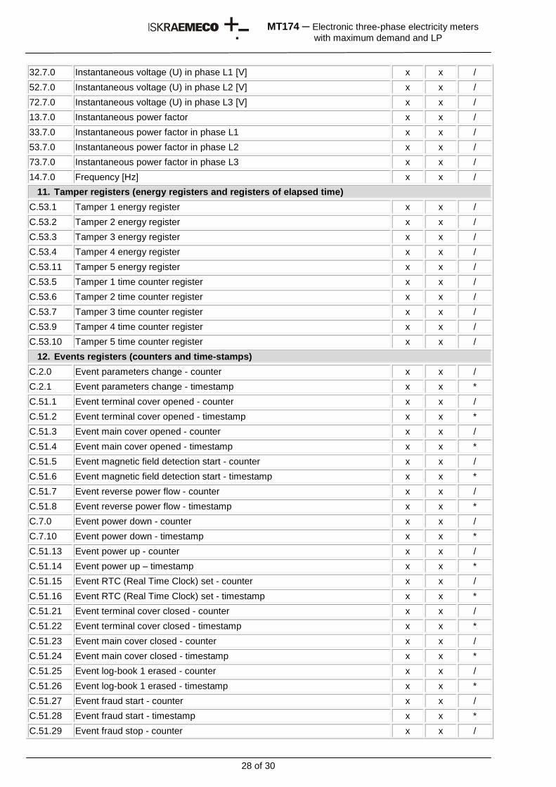
28 of 30
MT174 ─ Electronic three-phase electricity meters
with maximum demand and LP
32.7.0 Instantaneous voltage (U) in phase L1 [V] x x /
52.7.0 Instantaneous voltage (U) in phase L2 [V] x x /
72.7.0 Instantaneous voltage (U) in phase L3 [V] x x /
13.7.0 Instantaneous power factor x x /
33.7.0 Instantaneous power factor in phase L1 x x /
53.7.0 Instantaneous power factor in phase L2 x x /
73.7.0 Instantaneous power factor in phase L3 x x /
14.7.0 Frequency [Hz] x x /
11. Tamper registers (energy registers and registers of elapsed time)
C.53.1 Tamper 1 energy register x x /
C.53.2 Tamper 2 energy register x x /
C.53.3 Tamper 3 energy register x x /
C.53.4 Tamper 4 energy register x x /
C.53.11 Tamper 5 energy register x x /
C.53.5 Tamper 1 time counter register x x /
C.53.6 Tamper 2 time counter register x x /
C.53.7 Tamper 3 time counter register x x /
C.53.9 Tamper 4 time counter register x x /
C.53.10 Tamper 5 time counter register x x /
12. Events registers (counters and time-stamps)
C.2.0 Event parameters change - counter x x /
C.2.1 Event parameters change - timestamp x x *
C.51.1 Event terminal cover opened - counter x x /
C.51.2 Event terminal cover opened - timestamp x x *
C.51.3 Event main cover opened - counter x x /
C.51.4 Event main cover opened - timestamp x x *
C.51.5 Event magnetic field detection start - counter x x /
C.51.6 Event magnetic field detection start - timestamp x x *
C.51.7 Event reverse power flow - counter x x /
C.51.8 Event reverse power flow - timestamp x x *
C.7.0 Event power down - counter x x /
C.7.10 Event power down - timestamp x x *
C.51.13 Event power up - counter x x /
C.51.14 Event power up – timestamp x x *
C.51.15 Event RTC (Real Time Clock) set - counter x x /
C.51.16 Event RTC (Real Time Clock) set - timestamp x x *
C.51.21 Event terminal cover closed - counter x x /
C.51.22 Event terminal cover closed - timestamp x x *
C.51.23 Event main cover closed - counter x x /
C.51.24 Event main cover closed - timestamp x x *
C.51.25 Event log-book 1 erased - counter x x /
C.51.26 Event log-book 1 erased - timestamp x x *
C.51.27 Event fraud start - counter x x /
C.51.28 Event fraud start - timestamp x x *
C.51.29 Event fraud stop - counter x x /
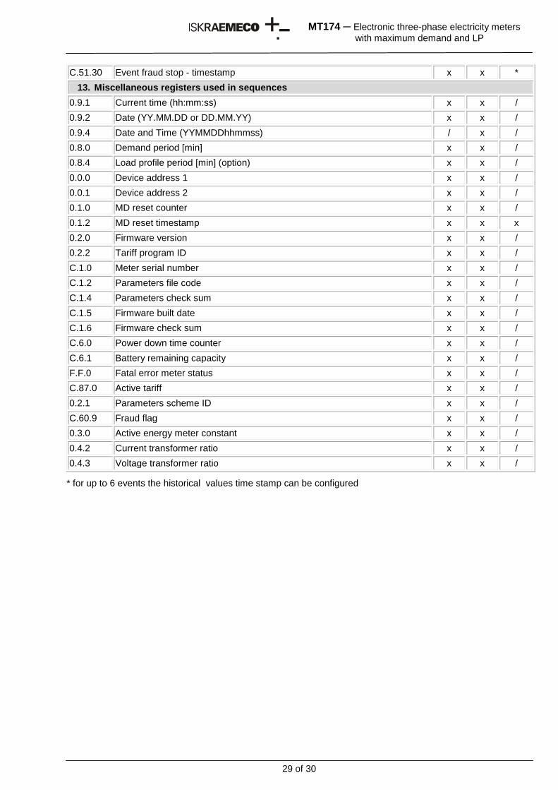
29 of 30
MT174 ─ Electronic three-phase electricity meters
with maximum demand and LP
C.51.30 Event fraud stop - timestamp x x *
13. Miscellaneous registers used in sequences
0.9.1 Current time (hh:mm:ss) x x /
0.9.2 Date (YY.MM.DD or DD.MM.YY) x x /
0.9.4 Date and Time (YYMMDDhhmmss) / x /
0.8.0 Demand period [min] x x /
0.8.4 Load profile period [min] (option) x x /
0.0.0 Device address 1 x x /
0.0.1 Device address 2 x x /
0.1.0 MD reset counter x x /
0.1.2 MD reset timestamp x x x
0.2.0 Firmware version x x /
0.2.2 Tariff program ID x x /
C.1.0 Meter serial number x x /
C.1.2 Parameters file code x x /
C.1.4 Parameters check sum x x /
C.1.5 Firmware built date x x /
C.1.6 Firmware check sum x x /
C.6.0 Power down time counter x x /
C.6.1 Battery remaining capacity x x /
F.F.0 Fatal error meter status x x /
C.87.0 Active tariff x x /
0.2.1 Parameters scheme ID x x /
C.60.9 Fraud flag x x /
0.3.0 Active energy meter constant x x /
0.4.2 Current transformer ratio x x /
0.4.3 Voltage transformer ratio x x /
* for up to 6 events the historical values time stamp can be configured
30 of 30
MT174 ─ Electronic three-phase electricity meters
with maximum demand and LP
Owing to periodically improvements of our products the supplied products can differ in some details from data stated in this technical description.
Iskraemeco d.d., Energy Measurement and Management 4000 Kranj, Savska loka 4, Slovenia Telephone (+386 4) 206 40 00, Fax: (+386 4) 206 43 76 http://www.iskraemeco.si, E-mail: [email protected] Published: Iskraemeco, Marketing, Data subjected to alteration without notice. MT174_TD_v10_Eng_sh.doc