Embed Size (px)
Citation preview
Energy Metrics for Product Assembly Equipment and Processes
Shaw C. Feng, Senthilkumaran Kumaraguru, Christopher U. Brown, and Boonserm Kulvatunyou National Institute of Standards and Technology
Gaithersburg, Maryland 20899 Abstract A key factor deciding the capacity to increase the sustainability of final products is the energy efficiency. The energy embodied in a product is an aggregation of all of the energy embodied in the products’ components and subsystems, expended through its manufacturing processes and logistical activities. Currently, accurate estimation of this energy metric is hindered due to the unavailability of energy use data traceable to individual processes and equipment associated with the product’s assembly. In this paper, we propose using minimally-required energy to compute energy efficiency of a product assembly process. Based on the proposed approach, efficiency metrics established on the process, product, material and equipment characteristics have been presented at the assembly activity and equipment level. A case study has been presented for a hybrid laser welding process to demonstrate the computational methods used to arrive at these efficiency metrics. Major contributions of this paper are the metrics development and exemplifying the metrics through an actual assembly process (hybrid laser welding) case study. We will explain how these metrics can provide industries with a capability to identify opportunities to improve their sustainability performance across their assembly processes. Key words: assembly equipment, assembly process, energy metrics, sustainable manufacturing, sustainability measurement. 1. Introduction The number of manufacturing companies that are making fundamental changes towards sustainability is increasing around the world [1, 2]. Many global automotive manufacturers have research efforts focused on improving energy efficiency in assembly processes [3]. These companies recognize that challenges in energy improvement include 1) performing reliable energy assessment of part assemblies and 2) evaluating energy efficiency before, during, and after an assembly process. However, there is a major technical problem: measuring energy consumption is rarely traceable to individual processes and equipment. Because of this, the reported energy usually has large uncertainty due to subjective allocation. The uncertainty hinders sound analyses of energy performance1 in assembly processes, and reporting energy performance to the public and stakeholders. Industry needs an equitable energy metric for analysis and verification of energy use in product assembly processes.
1 Energy performance is the ratio of the amount of production to a unit amount of energy.
An assembly process [4] is conceptually an aggregation of part delivery, workpiece handling, fixturing, joining, and other auxiliary operations. Major joining processes include welding, brazing, soldering, bonding, riveting, and fastening. Most research on assembly processes are primarily focused on process technologies, capabilities, and product design for assembly processes [5-7]. Little research is focused on measurement science for assessing energy efficiency and energy performance of assembly processes. As types of assembly processes are numerous and complex, we established the scope of this paper on energy transformation, focusing on joining. Joining is the method to assemble separate parts into one piece without relative movement, e.g., mounting chips to the printed circuit board by soldering. Subcategories of joining include adhesive bonding, welding, and mechanical fastening. Welding can be further classified as fusion, brazing or soldering, and solid state joining. Fusion breaks down even further into electric welding and chemical welding. This paper provides a detailed analysis of energy performance-related metrics, methods for the computation of energy efficiency, and a case study of welding. Section 2 explains metrics used for computing energy transformation in product assembly processes. Section 3 has an example of energy analysis based on the metric. Section 4 concludes the paper. 2. Metrics for Energy in Assembly Processes Energy is transformed while performing tasks in assembly processes. Measuring to quantify energy efficiency and then reducing energy consumption in product assemblies are steps towards improving the energy performance of an assembled product. This section describes energy metrics, an energy transformation model for assembly equipment, activity, and process. 2.1 Definition of Metric Metric is defined as a standard measure of a single parameter of a system. A metric has the following characteristics: measurable, relevant, understandable, reliable, usable, data accessible, timely, and long term-oriented [8]. Metrics enable companies to quantify the energy performance of their manufacturing processes, including energy efficiency. Quantifiable performance can lead to performance improvement. Our work is focused on energy efficiency as a metric for assembly processes. Determining energy efficiency involves quantifying energy consumption, loss, and minimally required energy. A product is assembled in a predefined sequence of assembly activities defined by the assembly process plan of the product. Additionally, energy metrics can be modularly composed to support many production scenarios without redefinition in the energy efficiency analysis. Energy may be consumed by multiple pieces of equipment to support multiple processes within an assembly activity. Energy consumption is another metric for an assembly activity. Modeling energy transformation of an assembly activity involves quantification of energy consumed by both equipment and processes. The rest of this section describes the energy transformation model and energy efficiency metrics starting from equipment to processes.
2.2 Measuring energy at the equipment level Energy consumed by assembly processes is primarily consumed by powered equipment (eQuipment or Q). Major functions of powered assembly equipment are material handling, thermal joining, powered fastening, fixturing, and adhesive bonding. For characterizing energy transformation in equipment, we define a new concept: Unit eQuipment (UQ). UQ is a piece of equipment that has a specific function, such as welding or material handling, and a defined boundary. The boundary is the interface between the equipment and its surroundings. Energy flows in and out of the equipment boundary. Unit equipment has energy input and can have energy or work as output. Pieces of unit equipment can be combined into Complex Equipment (CQ). Complex equipment consists of two or more pieces of unit equipment and hence can have one or more energy inputs. Each unit equipment piece in the complex equipment has its own energy input. For example, an automated arc-welding machine consists of a robot and a welder. The robot and the welder have their own energy inputs. The energy consumed by the equipment (machine, work cell, or assembly line) is defined as Energy Input (
). Examples of the energy input source are electricity, fuel, and natural gas. The
energy from the equipment actually available to the workpiece is defined as Energy output ( )
and is considered as useful energy, i.e., exergy2. One example of exergy is heat generated by the welding electrode to weld two pieces of metal parts. Another example is mechanical work done during a robot motion to move the welder along the seam. While efficiently utilizing exergy to maximize sustainable efficiencies during the assembly process, quantifying exergy is outside the scope of this paper. Energy input is greater than energy output from the assembly equipment. The difference between the energy input and the energy output is defined as Energy Lost. Energy lost is due to many reasons. Examples are irreversible processes (such as energy conversion losses, vibration, and friction) and heat exhausted from the equipment to the ambient environment. The Energy Efficiency ( Q) of equipment is defined as the percentage of useful energy from the energy input. Equation (1) is the efficiency of a piece of equipment.
(1)
For complex equipment, the efficiency ( CQ) is the energy output from the complex equipment divided by the energy input to the complex equipment. The energy input and output of a piece of complex equipment is the sum of energy input/output of unit equipment pieces. Note that the energy units of all the energy inputs and outputs have to be consistent. Equation (2) is the efficiency of a piece of complex equipment, where n is the total number of unit equipment pieces in the complex equipment piece and i is an index from 1 to n. 2 Exergy is the maximum useful heat or work brought by the equipment into the workpiece(s) in a process.
∑
∑
(2)
Furthermore, equipment is classified into assembly and auxiliary equipment. Assembly eQuipment (AQ) delivers energy directly to the assembly process. Auxiliary eQuipment (auxQ) delivers energy directly to auxiliary processes, not directly to the assembly process. An auxiliary process is necessary for the assembly process to complete. For example, in welding, heat energy for the process is contributed by the arc welding equipment whereas the motion controllers and fume hood are considered auxiliary equipment. The assembly process and auxiliary processes concurrently take place during an assembly activity to complete an assembly task, such as welding a seam or placing chips to a Printed Circuit Board (PCB) in a reflow soldering process. When measuring energy input or output of a piece of equipment, such as a welding machine, the first step is to describe what parameters of the equipment should be measured and how they are measured. Some fundamental elements for measuring the parameters includes operations, measurement instrument to be used, measurement setup, instrument calibration certificates, instrument and equipment interface, and documentation of any models and simulations employed. Measurement methods may also include virtual measurements using computational models and simulations. The second step is to document the measurement results which provide transparency and traceability. A measurement result includes the statement of a measured value and the associated measurement uncertainty, such as described in the ISO standardized approach in the Guide to the Expression of Uncertainty in Measurement [9, 10]. Determining the measurement uncertainty requires identifying all the known sources and the magnitudes of uncertainty and their aggregation. There are multiple ways to specify uncertainty, such as confidence interval, standard deviation, or probability distribution. Thus, the uncertainty quantification must be consistent with the purpose of measurement. The last step is to describe contextual information. Contextual information includes information about the organization, the stage in a product’s lifecycle, the time duration of the measurement, location, and the data on the operator. A typical energy measurement process is defined by three phases: plan, implement, and review [11]. The prerequisite for quality in sustainability measurement is that measuring methods should be based on standard procedures, commonly accepted terminology, instrument certifications, and standard reference materials. 2.3 Measuring energy efficiency in an assembly activity Energy available from equipment is used in an Assembly Process (AP) to assemble individual parts and components (i.e., workpieces) into a product. Examples of assembly processes (APs) that require energy input to join workpieces are thermal joining processes, automated
fastening processes, and chemical bonding processes. A joining process, such as welding, requires a certain amount of energy to raise the workpiece temperature to melt the material. The total energy input to an AP is the summation of the energy from all the pieces of equipment involved in the assembly activity. Equation (3a) shows the total energy output (O) by n pieces of AQ involved in the AP, and i is an index from 1 to n.
∑
(3a)
The energy input to all AQ is denoted by
. Equation (3b) shows the total energy input to m
pieces of AQ involved in the assembly process, and i is an index from 1 to n.
∑
(3b)
The energy input to all auxiliary equipment, which does not contribute to
, is denoted by
. Equation (3c) shows the total energy input to m’ pieces of auxiliary equipment (auxQ)
involved in the assembly activity, and i is an index from 1 to m.
∑
(3c)
The minimal amount of energy required by the workpieces to be assembled is defined as Required (R) Energy (
). Required energy can be obtained either by measurements or by theoretical estimation. For example, the required energy input for a welding process can be measured by calorimetric experiments or can be theoretically estimated. The theoretically calculated amount of energy is called Theoretically Required (TR) Energy (
). In many cases, theoretically required energy is approximate or equal to the amount of energy needed to assemble workpieces because the material properties and behaviors of the workpieces are usually idealized for computations. Given this, let be the error in the theoretical estimation, Equation (4) shows the relationship for required energy.
(4) The energy lost is called Processing Energy Lost (
). Equation (5) describes .
(5) A major advantage of characterizing processing energy lost is to implement energy recovery systems to improve the energy efficiency if possible. This metric also allows manufacturers to identify opportunities for optimization of process parameters to minimize energy lost and increase energy efficiency. The efficiency of an assembly process ( AP) is defined as the required energy by an assembly process divided by the total energy input to the assembly process (
) as in Equation (6).
(6)
The total amount of energy input to the Assembly Activity (AA)
is the sum of the total energy input to all the assembly equipment,
as expressed in Equation (3b), and the total
energy input to all the auxiliary equipment, as expressed in Equation (3c).
can thus
be calculated using Equation (7).
(7)
The efficiency of an assembly activity ( AA) can be defined as the required energy by the assembly process divided by the total energy input to the assembly activity (
) as in Equation (8).
(8)
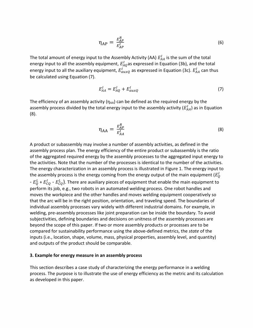
A product or subassembly may involve a number of assembly activities, as defined in the assembly process plan. The energy efficiency of the entire product or subassembly is the ratio of the aggregated required energy by the assembly processes to the aggregated input energy to the activities. Note that the number of the processes is identical to the number of the activities. The energy characterization in an assembly process is illustrated in Figure 1. The energy input to the assembly process is the energy coming from the energy output of the main equipment (
-
+ -
). There are auxiliary pieces of equipment that enable the main equipment to
perform its job, e.g., two robots in an automated welding process. One robot handles and moves the workpiece and the other handles and moves welding equipment cooperatively so that the arc will be in the right position, orientation, and traveling speed. The boundaries of individual assembly processes vary widely with different industrial domains. For example, in welding, pre-assembly processes like joint preparation can be inside the boundary. To avoid subjectivities, defining boundaries and decisions on unitness of the assembly processes are beyond the scope of this paper. If two or more assembly products or processes are to be compared for sustainability performance using the above-defined metrics, the state of the inputs (i.e., location, shape, volume, mass, physical properties, assembly level, and quantity) and outputs of the product should be comparable. 3. Example for energy measure in an assembly process This section describes a case study of characterizing the energy performance in a welding process. The purpose is to illustrate the use of energy efficiency as the metric and its calculation as developed in this paper.
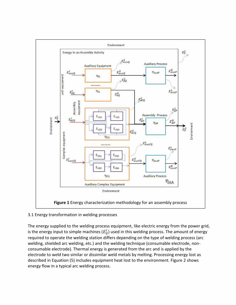
3.1 Energy transformation in welding processes The energy supplied to the welding process equipment, like electric energy from the power grid, is the energy input to simple machines (
) used in this welding process. The amount of energy
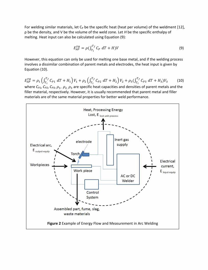
required to operate the welding station differs depending on the type of welding process (arc welding, shielded arc welding, etc.) and the welding technique (consumable electrode, non-consumable electrode). Thermal energy is generated from the arc and is applied by the electrode to weld two similar or dissimilar weld metals by melting. Processing energy lost as described in Equation (5) includes equipment heat lost to the environment. Figure 2 shows energy flow in a typical arc welding process.
Figure 1 Energy characterization methodology for an assembly process
For welding similar materials, let CP be the specific heat (heat per volume) of the weldment [12], ρ be the density, and V be the volume of the weld zone. Let H be the specific enthalpy of melting. Heat input can also be calculated using Equation (9):
∫
(9)
However, this equation can only be used for melting one base metal, and if the welding process involves a dissimilar combination of parent metals and electrodes, the heat input is given by Equation (10).
(∫
) (∫
) ∫
(10)
where CP1, CP2, CP3, are specific heat capacities and densities of parent metals and the filler material, respectively. However, it is usually recommended that parent metal and filler materials are of the same material properties for better weld performance.
Figure 2 Example of Energy Flow and Measurement in Arc Welding
The uncertainties ( ) in estimating is influenced by the measurement errors in material
property estimations. The volume of weld zone (V) used in equation (9) is usually dictated by design and type of join. Amount of heat input required for the volume of weld also need to account for the exergy loss during the process. The exergy loss during heating and cooling in welding will be governed by the initial temperature (i.e., ambient temperature). The ratio of exergy to energy is usually indicated by the exergy factor3 and this loss poses additional heat requirements in the case of welding.
Exergy factor = |
| (10a)
Computational estimation of weld volume through virtual heat transfer weld simulations will be usually less than the actual designed weld volume if the exergy losses are not compensated during the estimation of energy required. The energy input metric for different heat sources is presented through Equations (11 – 13). In arc power sources, energy input can be calculated using the following equation based on the voltage (U), current (I), weld length (l), and welding speed (S):
(11)
Whereas for laser power sources, energy input can be calculated using the following equation based on the power input (Pin), absorptivity (A), weld length (l), and welding speed (S):
(12)
In the case of electron beam power sources, energy input can be calculated using the following equation based on the power density (P) of the electron beam, the beam control efficiency ( ), the conversion efficiency ( ), weld length (l), and welding speed (S):
(13)
Many attempts have been made in the past to validate the above energy input models through extensive calorimetric measurements in Gas Metal Arc Welding (GMAW) [13], Plasma arc welding [14], Gas Tungsten Arc welding [15], laser welding [16] and electron beam welding [16]. Some of these experiments quantify the amount of heat input and the melting efficiency of the various power sources. In some occasions, process heat recovery systems can be implemented to recover a portion of lost energy. Examples of the equipment used in welding processes are power sources (arc, laser, electron beam), robots, wire feeders, fume hoods, chillers, gas supply units, electrode manufacturing, and cleaning and part preparation machines. Each of these pieces of equipment
3 For details, see Chapter 6 in Thermodynamics and the Destruction of Resources by B. Bakshi, T. Gutowski, and D.
Sekulic, Cambridge University Press, 2012.
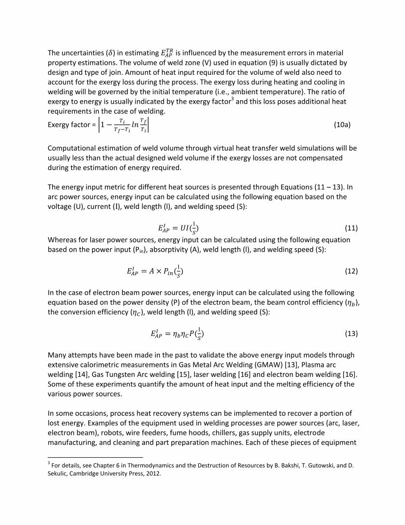
operates with certain energy. For example, many of the laser sources operate at 10 % of the stated value. Laser power meters are usually used to monitor the efficiency of the energy delivery during the use phase of the equipment. Similarly, robots are usually monitored and maintained for their stated energy efficiencies. Usually, energy efficiency of the equipment tends to decrease with the life of the equipment if it is not properly maintained. Even though a smaller number of lifecycle inventory data for the arc welding process exist in the commercial and open source life cycle inventory databases, more rigorous computational models need to be developed to better predict the energy efficiency based on science-based computational models. In this paper, an attempt is made to evaluate the efficiency of a welding process through finite element simulation of energy delivery. 3.2 Case Study - Hybrid Laser Gas Metal Arc Welding To illustrate the methodology proposed in this paper, a hybrid laser GMAW process is selected for characterizing the energy performance. First, a simulation is developed for studying energy transformation in the welding process. Second, the theoretical minimum energy required for welding is computed and efficiency is calculated only using the main equipment (43.65%). Lastly, the overall efficiency is calculated by including energy consumed by auxiliary equipment (10.93%). Hybrid Laser GMAW is widely used in various industries because of its high welding speeds. Due to high welding speeds, heat build-up and residual stresses are less and hence good weld quality is achieved. In Hybrid Laser GMAW, an arc power source is used along with a laser power source [17]. In this paper, energy metrics described in Section 4 are presented through a case study on Hybrid laser GMAW welding process. The gate-to-gate boundary of the chosen process is depicted in Figure 3. Some of the equipment used in this process and its efficiencies [18] are listed in Table 1. In Hybrid Laser GMAW, the energy required for the arc is supplied by both the laser and the electric arc.
Table 1 Equipment and process efficiencies for Hybrid laser GMAW welding process
Equipment Remarks Laser Power source 0.3 Electrical to Optical
GMAW Power source 0.786 Electrical to Thermal
GMAW wire feeder 0.9 Electrical to Mechanical
Chiller 0.9 Thermal to Thermal
Motion Controller (Robot) 0.9 Electrical to Mechanical
Fume Hood 0.9 Electrical to Fluid flow
To determine the amount of heat input and to quantify the heat loss, a transient heat
conduction problem is formulated. The schematic of the model taken for this study is illustrated
in Figure 4. The material considered in the present study is austenitic stainless steel. The
various properties of the materials used are tabulated in Table 2. Proper initial and boundary
conditions are applied in the model, shown in Figure 4. The laser heat source is modeled as a
heat flux boundary condition and the arc heat source is modeled as heat source. The welding
speed considered is 0.7 m/minute. The time required to complete the welding is 12.23 s. An
adaptive meshing technique is used to mesh the model. The element type used to construct the
numerical model is solid 70 in ANSYS. In this type of meshing, fine mesh is used for the weld
bead area and a coarse mesh is used for areas other than the weld bead.
Figure 3 Energy flow in Hybrid Laser GMAW process
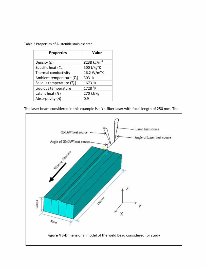
Table 2 Properties of Austenitic stainless steel
Properties Value
Density ( ) 8238 kg/m3
Specific heat ( ) 500 J/kgoK
Thermal conductivity 16.2 W/moK
Ambient temperature ( ) 303 oK Solidus temperature ( ) 1673 oK
Liquidus temperature 1728 oK
Latent heat ( ) 270 kJ/kg
Absorptivity (A) 0.9
The laser beam considered in this example is a Yb-fiber laser with focal length of 250 mm. The
Figure 4 3-Dimensional model of the weld bead considered for study
fiber diameter of 200 µm is assumed to get the spot diameter of 0.33 mm. The GMAW heat source considered in this study is a GMA arc welding machine with 5 kW of peak GMA power. The model of the Hybrid Laser GMAW process consists of a combination of two types of heat source equations namely a laser heat source and a GMA welding heat source. The laser heat source is represented by a Gaussian heat source as given in Equation (14) [19]
(
) (14)
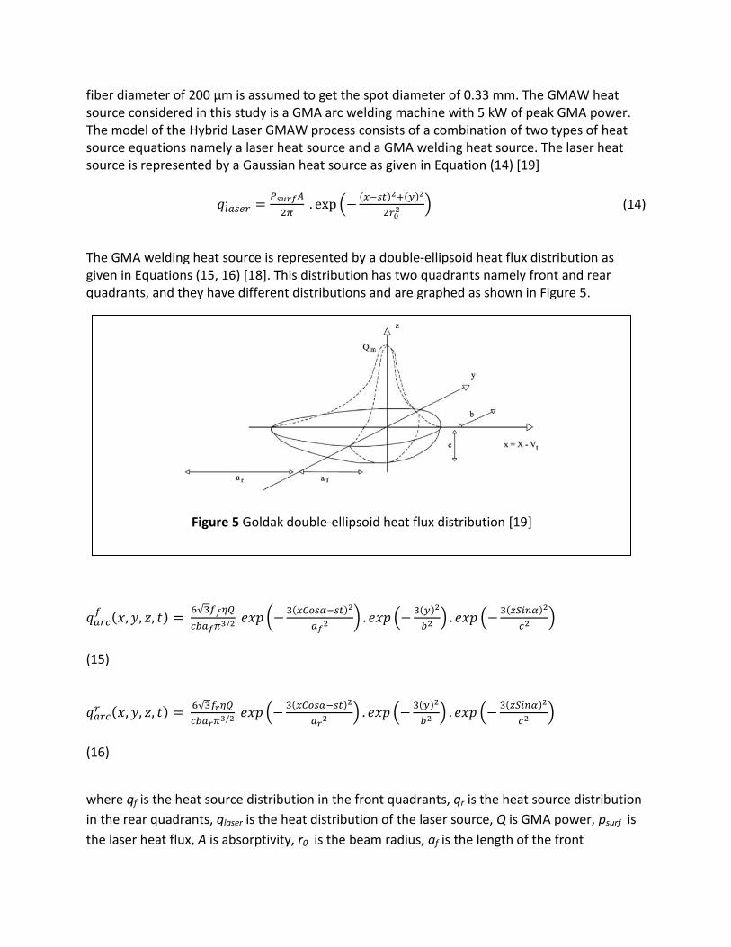
The GMA welding heat source is represented by a double-ellipsoid heat flux distribution as given in Equations (15, 16) [18]. This distribution has two quadrants namely front and rear quadrants, and they have different distributions and are graphed as shown in Figure 5.
√
(
) (
) (
)
(15)
√
(
) (
) (
)
(16)
where qf is the heat source distribution in the front quadrants, qr is the heat source distribution
in the rear quadrants, qlaser is the heat distribution of the laser source, Q is GMA power, psurf is
the laser heat flux, A is absorptivity, r0 is the beam radius, af is the length of the front
Figure 5 Goldak double-ellipsoid heat flux distribution [19]
quadrants, ar is the length of the rear quadrants, b is the half width of the heat source, c is the
depth of the heat source, s is the welding speed, α is the flow front angle, and η is the GMA
efficiency. The laser heat source equation indicates the energy distribution along the weld bead,
whereas the GMA welding source equations indicate the volumetric distribution of heat in the
front and rear quadrants. The loading used to construct the numerical model is discrete, like
steps. After applying the loads and boundary conditions the constructed model is solved by
transient thermal analysis using a commercial Finite Element Method (FEM) code in ANSYS.
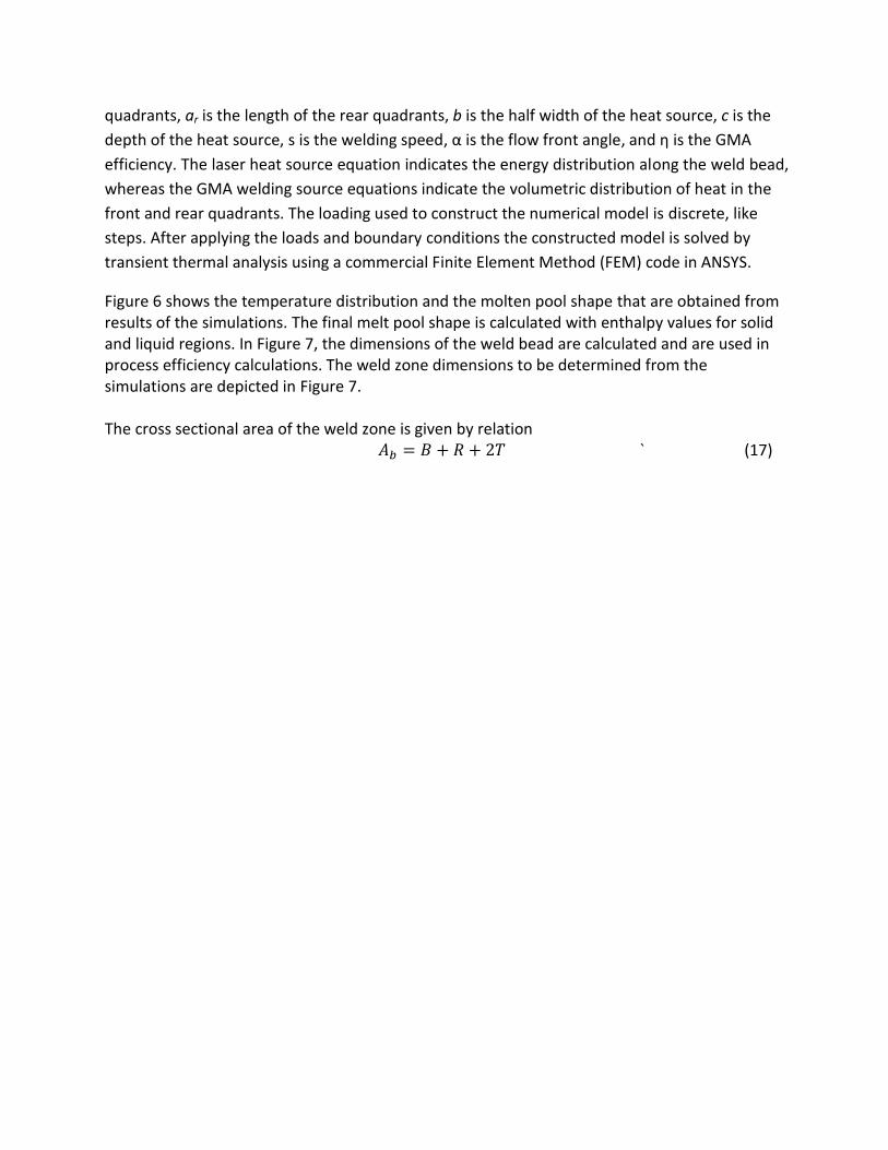
Figure 6 shows the temperature distribution and the molten pool shape that are obtained from results of the simulations. The final melt pool shape is calculated with enthalpy values for solid and liquid regions. In Figure 7, the dimensions of the weld bead are calculated and are used in process efficiency calculations. The weld zone dimensions to be determined from the simulations are depicted in Figure 7. The cross sectional area of the weld zone is given by relation
` (17)
Whereas, B, R and T are found geometrically by the relation
(a) Temperature profiles along the direction of weld on different locations at different times
(b) Temperature distribution and (c) Final melt pool shape at 12.93s
Figure 6 Results of the transient analysis
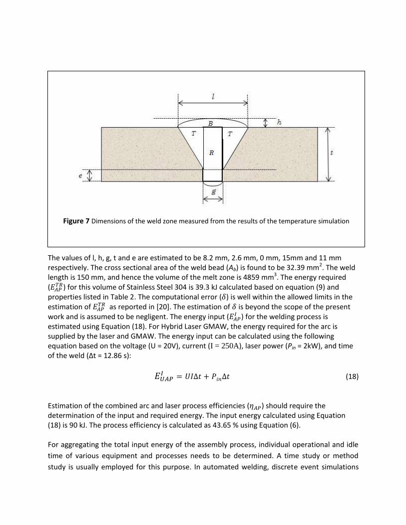
The values of l, h, g, t and e are estimated to be 8.2 mm, 2.6 mm, 0 mm, 15mm and 11 mm respectively. The cross sectional area of the weld bead (Ab) is found to be 32.39 mm2. The weld length is 150 mm, and hence the volume of the melt zone is 4859 mm3. The energy required (
) for this volume of Stainless Steel 304 is 39.3 kJ calculated based on equation (9) and properties listed in Table 2. The computational error ( ) is well within the allowed limits in the estimation of
as reported in [20]. The estimation of is beyond the scope of the present work and is assumed to be negligent. The energy input (
) for the welding process is estimated using Equation (18). For Hybrid Laser GMAW, the energy required for the arc is supplied by the laser and GMAW. The energy input can be calculated using the following equation based on the voltage (U = 20V), current (I = 250A), laser power (Pin = 2kW), and time of the weld (∆t = 12.86 s):
(18)
Estimation of the combined arc and laser process efficiencies ( ) should require the determination of the input and required energy. The input energy calculated using Equation (18) is 90 kJ. The process efficiency is calculated as 43.65 % using Equation (6). For aggregating the total input energy of the assembly process, individual operational and idle
time of various equipment and processes needs to be determined. A time study or method
study is usually employed for this purpose. In automated welding, discrete event simulations
Figure 7 Dimensions of the weld zone measured from the results of the temperature simulation

can be used to estimate the individual operating time of the equipment and processes. A
representative example for cycle time for the hybrid welding process is illustrated in Figure 8.
Weld cycle time (tw) = Total arc and laser time + Robot Positioning time + Track movement time + sensing time + setup time.
In this paper, the idle time for the chiller, GMAW power source, laser power source, robot and
fume hood are assumed to be 30%, 60 %, 60%, 28% and 0% respectively. To understand the
methodology presented in Section 4, the calculation of energy metrics for the hybrid welding
process is included in Table 3. The data presented in Table 3 are for one hour operation of
hybrid laser welding equipment and accessories. The total efficiency (AP) of the process is
calculated as 10.93 % for the hybrid laser welding process. This efficiency of the process is
obtained using the stated process parameter values and usually this efficiency is a function of
process parameters and should be estimated when there is a change of process parameters.
This methodology could be used to obtain the efficiency for similar welding processes. The
operational and idle times of equipment may widely vary with many industries and the
uncertainties in measuring efficiency of equipment are not addressed and are beyond the
scope of this paper.
Figure 8 Total cycle time in a robotic arc welding process.
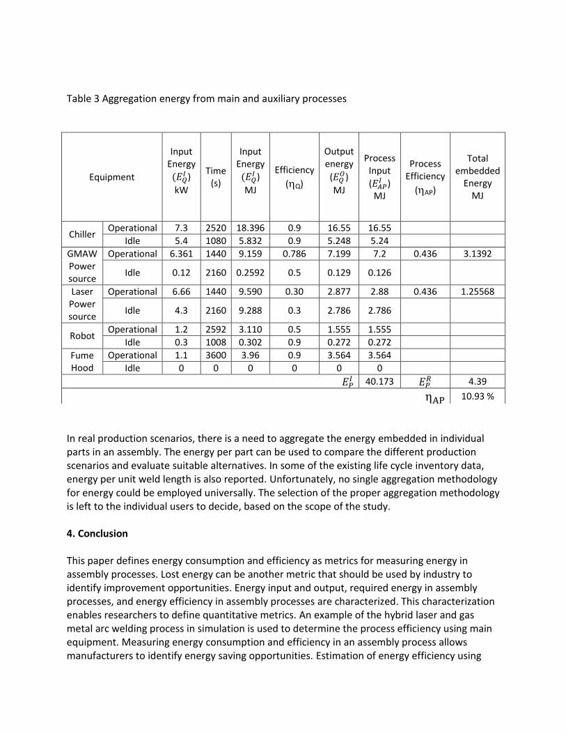
Table 3 Aggregation energy from main and auxiliary processes
In real production scenarios, there is a need to aggregate the energy embedded in individual parts in an assembly. The energy per part can be used to compare the different production scenarios and evaluate suitable alternatives. In some of the existing life cycle inventory data, energy per unit weld length is also reported. Unfortunately, no single aggregation methodology for energy could be employed universally. The selection of the proper aggregation methodology is left to the individual users to decide, based on the scope of the study. 4. Conclusion This paper defines energy consumption and efficiency as metrics for measuring energy in assembly processes. Lost energy can be another metric that should be used by industry to identify improvement opportunities. Energy input and output, required energy in assembly processes, and energy efficiency in assembly processes are characterized. This characterization enables researchers to define quantitative metrics. An example of the hybrid laser and gas metal arc welding process in simulation is used to determine the process efficiency using main equipment. Measuring energy consumption and efficiency in an assembly process allows manufacturers to identify energy saving opportunities. Estimation of energy efficiency using
Equipment
Input Energy
)
kW
Time (s)
Input Energy
)
MJ
Efficiency
(Q)
Output energy
( )
MJ
Process Input
( )
MJ
Process Efficiency
(AP)
Total embedded
Energy MJ
Chiller Operational 7.3 2520 18.396 0.9 16.55 16.55
Idle 5.4 1080 5.832 0.9 5.248 5.24
GMAW Power source
Operational 6.361 1440 9.159 0.786 7.199 7.2 0.436 3.1392
Idle 0.12 2160 0.2592 0.5 0.129 0.126
Laser Power source
Operational 6.66 1440 9.590 0.30 2.877 2.88 0.436 1.25568
Idle 4.3 2160 9.288 0.3 2.786 2.786
Robot Operational 1.2 2592 3.110 0.5 1.555 1.555
Idle 0.3 1008 0.302 0.9 0.272 0.272
Fume Hood
Operational 1.1 3600 3.96 0.9 3.564 3.564
Idle 0 0 0 0 0 0
40.173
4.39
10.93 %
computational heat transfer is illustrated for a representative assembly process. The terms and equations in this paper provide engineers with a means to evaluate the total energy consumption of an assembly process and its efficiency. More importantly, the total energy consumption and efficiency can be traced to detailed assembly processes and their subprocesses. Areas of interest for further development include extending the current work to other metrics for material and waste. Also, developing standards for the manufacturing industry to measure, analyze, and verify energy consumption and efficiency could provide new guides for energy performance improvement in assembly processes and assembled products. 5. Nomenclature – Absorptivity of parent materials
AA – Assembly Activity
auxQ – Auxiliary equipment
CQ – Complex equipment
– Specific heat capacity (kJ/ kg K)
E – Energy (kJ)
- Energy output of an equipment (kJ)
– Energy input of equipment (kJ)
– Energy output of a piece of equipment i (kJ)
- Energy input of a piece of equipment i (kJ)
– Required energy of assembly process (kJ)
– Energy output of all the auxiliary processes related to an assembly process (kJ)
– Theoretical required energy of assembly process (kJ)
– Energy input to an assembly process (kJ)
– Energy lost in an assembly process (kJ)
– Energy input of unit equipment (kJ)
– Energy output of unit equipment (kJ)
– Energy input of assembly equipment (kJ)
– Energy output of assembly equipment (kJ)
– Energy input of auxiliary equipment (kJ)
– Energy output of auxiliary equipment (kJ)
– Latent heat (kJ/m3)
– Peak current in welding power source (Amps)
AQ – Assembly equipment
– Total power input by laser power source (kJ/s)
Q - eQuipment
– Voltage of welding power source (Volts)
– Initial temperature (K)
– Final temperature (K)
– Liquidus temperature (K)
– Solidus Temperature (K)
– Volume of the weld zone (mm3)
– Heat flux generated by laser source (kJ/ mm2)
- Laser power distribution (kJ/mm2)
– Length of front quadrant (mm)
– Length of rear quadrant (mm)
– Half width of heat source (mm)
– Depth of the heat source (mm)
– fraction of heat source applied to front quadrant
- fraction of heat source applied to rear quadrant
– Heat source distribution in front quadrant
- Heat source distribution in rear quadrant
– Spot size or (beam radius) (mm)
S, s – welding speed
– Cycle time for the welding process (seconds)
t – welding time – Transformed x co-ordinate direction (xcosα)
– Transformed y co-ordinate direction (ysinα)
– Position of heat flux along x direction (mm)
- Position of heat flux along y direction (mm)
α – flow front angle (deg)
β – Liquid fraction
– Efficiency of an assembly operation
– Efficiency of complex equipment
– Efficiency of assembly process
– Equipment efficiency
– Assembly activity efficiency
- Density
– Error in theoretical estimation
Disclaimer
Certain commercial products may have been identified in this paper. These products were used only for demonstration purposes. This use does not imply approval or endorsement by NIST, nor does it imply that these products are necessarily the best for the purpose. References [1] Jovane, F., Yoshikawa, H., Alting, L., Boer, C., Westkamper, E., Williams, D., Tseng, M.,
Seliger, G., and Paci, A., “The incoming global technical and industrial revolution towards
competitive sustainable manufacturing,” CIRP Annals – Manufacturing Technology, Vol. 57, 2008, pp. 641 - 659.
[2] Haanaes, K., Balagopal, B., Kong, M., Velken, I., Arthur, D., Hopkins, M., and Kruschwitz, N., “New Sustainability Study: The ‘Embracers’ Seize Advantage,” MIT Sloan Management Review, Vol. 52, No. 3, March 2011.
[3] Department of Energy and United States Council for Automotive Research LLC , “Technology Roadmap for Energy Reduction in Automotive Manufacturing,” Troy, Michigan, September 2008.
[4] Kalpakjian, S. and Schmid, S., Manufacturing Engineering and Technology, 6th edition, Prentice Hall, New York, 2010.
[5] Whitney, D., Mechanical Assemblies: Their design, manufacture, and role in product development, Oxford University Press, Oxford, U.K., 2004.
[6] Sudarsan, R., Han, Y., Foufou, S., Feng, S., Roy, U., Wang, F., Sriram, R., and Lyons, K., “A Model for Capturing Product Assembly Information,” Transactions of ASME, Journal of Computing and Information Science in Engineering, Vol. 6, March 2006, pp. 11 – 21.
[7] Murshed, S.M., Dixon, A., and Shah, J. J., “Neutral Definition and Recognition of Assembly Features for Legacy Systems Reverse Engineering,” ASME 2009 International Design Engineering Technical Conferences and Computers and Information in Engineering Conference (IDETC/CIE2009), August 30–September 2, 2009 , San Diego, California, USA, Paper No DETC2009-86739.
[8] Sustainable Measures (2009), http://sustainablemeasures.com. [9] Joint Committee for Guides in Metrology (JCGM), Evaluation of measurement data —
“Guide to the expression of uncertainty in measurement” (JCGM 100:2008, GUM 1995 with minor corrections). International Bureau of Weights and Measures (BIPM), Paris, France, 2008.
[10] Joint Committee for Guides in Metrology (JCGM), Evaluation of measurement data — Supplement 1 to the “Guide to the expression of uncertainty in measurement” — Propagation of distributions using a Monte Carlo method (JCGM 101:2008), International Bureau of Weights and Measures (BIPM), Paris, France, 2008.
[11] ISO 14042, “Environmental management – Life cycle assessment – Life cycle impact assessment,” International Organization for Standardization (ISO), Geneva, Switzerland, 2000.
[12] Leibowitz, L. 1976. Properties for LMFBR safety analysis, Argonne National Labs: ANL-CEN-RSD-76-1.
[13] Dupont, J. N. and Marder A. R., “Thermal Efficiency of Arc Welding Processes,” Welding Journal, Vol. 74, 1995, pp. 406-416.
[14] Fuerschbach, P. W. and. Knorovsky G. A., “A Study of Melting Efficiency in Plasma Arc and Gas Tungsten Arc Welding,” Welding Journal, Vol. 70, 1991, pp. 287-297.
[15] Collings, N., Wong K. Y. and Guile A. E., “Efficiency of Tungsten -Inert Gas Arcs in Very High Speed Welding,” Proc. Inst. Electr. Engr., Vol. 126, 1979, pp. 276-280.
[16] Fuerschbach, P. W., “Measurement and Prediction of Energy Transfer Efficiency in Laser Beam Welding,” Welding Journal, Vol. 75, 1996, pp. 24-34.
[17] Swift-Hook, D. T. and. Gick A. E. F., “Penetration Welding with Lasers, Welding Journal,” Vol. 52, 1973, pp. 492s-499s.

[18] Bidi, L., Simone M., and Eugen C., ”The use of exploratory experimental designs combined with thermal numerical modeling to obtain a predictive tool for hybrid laser/MIG welding and coating process,” Optics and Laser Technology, Vol. 43, 2011, pp. 537-545.
[19] Goldak, J., Adithy, C., and Malcolm, B., “A Finite Element Model for Welding Heat Sources,” Metallurgical and Materials Transactions, Vol. 15, 1984, pp. 299-305.