Embed Size (px)
Citation preview
Energy Resources and Technology Prof. S. Banerjee
Department of Electrical Engineering Indian Institute of Technology - Kharagpur
Lecture - 16
Solar Concentrating Collectors
In the last class, we were talking about the solar thermal power conversion and we had
just introduced the solar flat plate collectors and we had gone into the solar concentrating
collectors and we have seen that, did I say this? There are two types of collectors,
concentrators, the imaging concentrators and non-imaging concentrators. Yes; so, we
were essentially talking about the imaging concentrators and one important class of
imaging, imaging concentrators were the parabolic concentrators.
(Refer Slide Time: 1:27)
So, the structure would be, where you have the parabolic trough kind of structure and
then you will have the focus somewhere here and naturally the absorber, the collector has
to be placed here, which will be in the form of a copper vessel blackened on the outside
and held with an arrangement something like this and the whole thing will then, will have
to move, will have to track the sun, so that all the time it faces the sun, because the sun’s
energy is concentrated only at the focus. So, if the sun goes off, then the point at which it
1
concentrates also goes off and therefore, if the sun goes off the main axis, then obviously
no energy will be concentrated on the collector. So, it has to have a very good tracking
system.
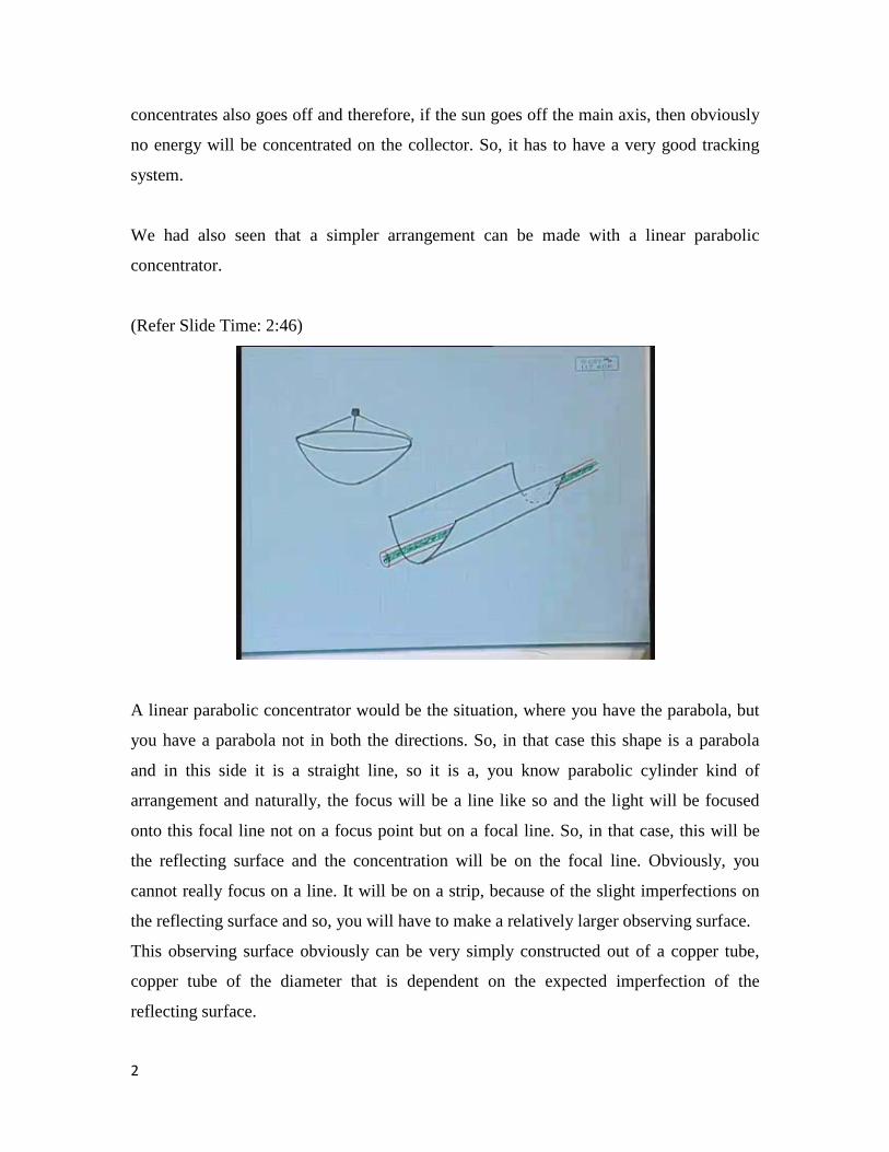
We had also seen that a simpler arrangement can be made with a linear parabolic
concentrator.
(Refer Slide Time: 2:46)
A linear parabolic concentrator would be the situation, where you have the parabola, but
you have a parabola not in both the directions. So, in that case this shape is a parabola
and in this side it is a straight line, so it is a, you know parabolic cylinder kind of
arrangement and naturally, the focus will be a line like so and the light will be focused
onto this focal line not on a focus point but on a focal line. So, in that case, this will be
the reflecting surface and the concentration will be on the focal line. Obviously, you
cannot really focus on a line. It will be on a strip, because of the slight imperfections on
the reflecting surface and so, you will have to make a relatively larger observing surface.
This observing surface obviously can be very simply constructed out of a copper tube,
copper tube of the diameter that is dependent on the expected imperfection of the
reflecting surface.
2
If it is perfect, then it can be very narrow. If it is relatively imperfect, depending on the
manufacturing process, then you will have to have a relatively larger diameter. But then,
how do you make the greenhouse effect on this? Greenhouse effect means you recall that
on the absorbing surface, the absorbing surface will also emit radiation and in order to
arrest that, we had put in case of flat plate collector a glass plate which would not allow,
which would allow the visible radiation to come in, but will not allow the infrared
radiation to go out. What can be done in this case? You can have, of course put a flat
plate. Very simple, you put a concentric cylinder of glass, so there would be a concentric
cylinder made of glass. Let me draw in red; then, the amendment becomes very simple,
that you have water flowing through this and you have some kind of a circulation system
and it goes through this. The manufacturing process will be very simple and even because
it is cylindrical in size, you can also withstand pressure and therefore, it is not impossible
to generate steam out of this, clear.
In fact, this is the type of the concentrating system that is more popular than this type
unless you are really going for very large scale power generation systems, which I will
come to later. So, in case your requirement is water of a temperature something like 60 to
80 degrees, then flat plate collectors are okay. If you are trying to generate hotter water
like 90 degrees or 100 degrees or steam, then this kind of collectors are better, but if you
want to make a power station kind of thing, then obviously this may not suffice and you
need to have more higher degree of concentration.
But, it is clear that if you have a two dimensional system that means this is a two
dimensional parabola or a 3-D parabola actually, then you need to have a two axis
tracking system. That means it has to be able to move this way, as well as this way, in
order to have the complete tracking of the sun. In case of this, obviously you need to only
move it this way, right. It is a one axis tracking system. That is why it is simpler, but even
people are trying to go for a higher degree of simplicity. Just imagine that if it is a
parabola with one side linear, then it can be placed either East West or North South, right.
So, can you imagine what would happen if you place this one in the East West orientation
and if you place this one in North South orientation? What will happen?
3
Let us first imagine that you are placing in the North South orientation. So, here is the
North, here is the South. In that case, sun rises to the East and goes on and sets to the
West and as a result, you need to tilt it towards this side in the morning and towards that
side in the evening. So, you will need a continuous tracking system, one axis tracking
system over the day, clear. Only thing is that since the sun’s position in the sky, the plane
in which it moves, changes with the season, therefore during the summer season it will be
more or less horizontal, in winter season it will have to be more or less at an angle. So,
there will have to be an arrangement of changing the tilt due to the seasonal change of the
position, clear. So, for the North South orientation, you have to have a one axis tracking
system that works all through the day and the tilt is decided dependent on the season.
Now suppose you orient it to the East West direction. So, in that case, imagine that here
is the East, here is the West. In that case the sun rises in the East goes off and sets in the
west. So, naturally all the time it is moving along the axis and therefore, you do not need
tracking, right, you do not need tracking then. So, that can be a very simple arrangement
where even the requirement for the tracking is eliminated. Only thing is that the plane in
which the sun will move will be dependent on the season and therefore, this tilt has to be,
this tilt, not this tilt, it is this tilt that has to be decided on the basis of the season. Is that
clear?
Next, another issue here. In the early morning, the sun will be coming from this side and
therefore, after reflection there will be a large part of the refill, of the absorber area here
which will not really receive the concentrated sun light, rather some amount of concerted
sun light will be received here beyond the range of the reflector. So, if you have to have
an East West orientation, the absorber size has to be larger than the reflector size, which
is not required in case of a North South orientation. So, the absorber, the glass sheet, all
that has to be larger than the reflector size, because for most part of the day the light will
actually be concentrated away, out of the range of the reflector. So, you see, here in this
kind of system, you can, it is possible to avoid, even though it is a parabolic concentrator,
it is possible to avoid the tracking system.
4
In some cases, the tracking systems can be messy. So, essentially if it is a standalone
system, not much attended to, then tracking system are not very ….. In many cases, you
have to do it in an isolated place with not much electricity supply or unreliable electricity
supply, in those cases, it is better to have a system without tracking. But, if you have it in
a reasonably well attended place, then a tracking system would be better, because it has a
larger concentration ratio, clear.
(Refer Slide Time: 12:20)
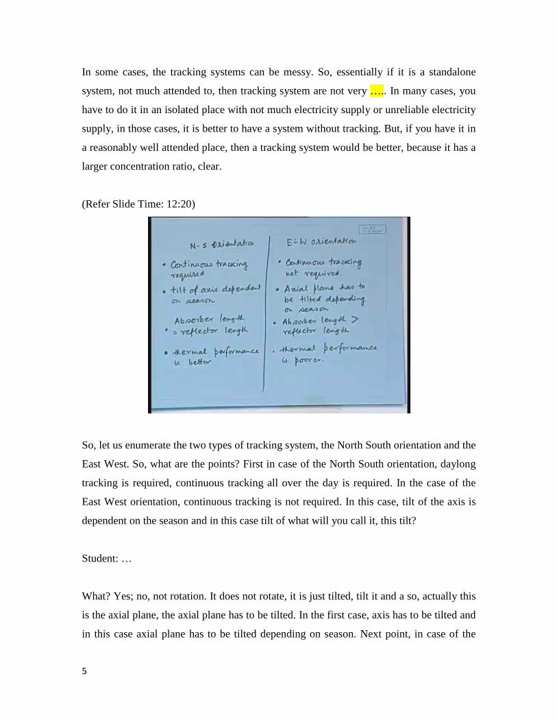
So, let us enumerate the two types of tracking system, the North South orientation and the
East West. So, what are the points? First in case of the North South orientation, daylong
tracking is required, continuous tracking all over the day is required. In the case of the
East West orientation, continuous tracking is not required. In this case, tilt of the axis is
dependent on the season and in this case tilt of what will you call it, this tilt?
Student: …
What? Yes; no, not rotation. It does not rotate, it is just tilted, tilt it and a so, actually this
is the axial plane, the axial plane has to be tilted. In the first case, axis has to be tilted and
in this case axial plane has to be tilted depending on season. Next point, in case of the
5
North South orientation, the absorber area can be the same as the reflector area or length,
absorber length can be the same as the reflector length and in this case the absorber
length has to be larger than the reflector length. But, which one will be better? As far as
the overall thermal performance is concerned, which one will absorb more amount of
energy? The first one, the North South tracking. You have the disadvantage that you have
to track it all the time, but the advantage that it gets you more energy. So, the thermal
performance is better. So, this is how they compare and depending on the specific
situations, people chose a particular kind of orientation and then they design accordingly.
What would the reflector be made of? You see, the reflector in your home is a glass with
a silver coating. Can you do this here? For various purposes, various reasons, no. Firstly
how to bend a glass in a parabolic shapes? Even if you do and somehow manage to silver
the other side, then the whole thing will be very brittle. I mean anything happens, it might
break. So, normally these are made of simply polished steel surface. So, these are steel
surface, metal surface, aluminum surface in many cases, but that is thoroughly polished,
so that they are proper reflecting surfaces. So, naturally if the place is such, like a big city
like Calcutta, there will be deposition of dust that reduces the reflection coefficient.
Obviously, you need to clean it; it is necessary to clean it.
Now, how can you put into effect the tracking system? In this kind of system, as I told
you that you will need a tracking system, in this case also you do, but if it is North South
orientation, but it is a one axis tracking system, nevertheless you will need a tracking
system. How to actually do the tracking system? Normally this is done by a very simple
mechanism. For any tracking system it has to be a feedback controller. That means if it is
going wrong, then there should be some kind of a generation of a voltage that is
proportional to the extent it has gone wrong and then, on the basis of that if motor is
turned and it is reoriented back to the proper position.
Now, the way it is normally done is by the use of small photovoltaic cells. What
photovoltaic cells are I will come to that later, but assume that there are cells that can
6
generate voltage or current. In fact these actually are current sources, so that they
generate current depending on the amount of solar radiation incident on it.
(Refer Slide Time: 19:44)
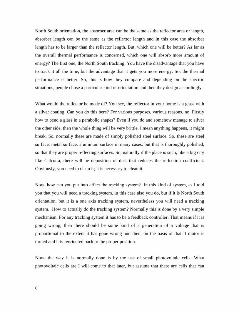
So, what is done is normally if you have say, imagine that you have a, you have to have a
one axis tracking system and you placed a photovoltaic panel here and some kind of a
barrier there, so here is one part of the panel photovoltaic cell, it is another part of
photovoltaic cell, equal size. So, normally if the solar radiation is coming from there, they
will produce equal voltage, equal current. If instead, the solar radiation is coming from
this side, then this will produce the full voltage, but a part of that will be shaded. As a
result, unequal amount of voltage and current will be generated. So, all you need to do is
to subtract these two voltages and use that as the error signal. So, depending on that
voltage, depending on the voltage generated, you will have a, you will turn a motor.
In case of a two axis tracking system, a similar thing has to be done also along the other
axis that is all. So, one axis the motor that actually turns it that will be governed by the
error signal generated this way and the other axis also it will be the same way. This is one
kind of tracking system where you actually use the feedback control. There is another
type of feedback control system. Here you see, the voltage that is generated, the
7
difference in the voltage that is generated is exactly proportional to the error that means
how much away from the exact alignment you have gone. If it comes from this side there
will be larger difference in the voltage, if it is more or less vertical, then there will be
smaller difference in the voltage. In the other words, I am saying that the voltage is an
analogue quantity, can take any value, right and on the basis of that you turn it.
In many implementations you will find that people find this not very convenient. So, they
have an implementer in which either the motor turns or it does not turn. So, in that case,
all they do is simply put a very small photovoltaic cell here and a very small photovoltaic
cell there, very small. Now, if the incident solar radiation falls, this will generate the
voltage, this will not at all, as a result of which the motor will turn and when it turns, it
turns at the same velocity. The turning, the speed of the turning does not depend on the
analogue voltage that is generated. The moment it becomes vertical, both the small
photovoltaic cells generates the same amount of current and therefore the difference
becomes zero and therefore the motor stops. This kind of a, of an implementation you
will find in our energy engineering laboratory in electrical department. Those who are
energy engineering students you will see this kind of tracking system actually used. So,
this is where you are actually using the feedback to obtain the position.
There are some difficulties in the sense that if there is a cloudy sky, there is no direction
in which the sun comes and therefore this fellow finds it difficult to orient it. If it is
cloudy sky, it is a diffused radiation and in case of diffused radiations, the difference will
not be significant at all and therefore, in case of diffused radiations, this fellow cannot
orient, but of course when the sun again comes out it, it immediately can readjust its
position and come to the proper position.
In case of relatively larger establishments, larger means where you have a more, where
you can afford more sophisticated control system there another type of control system is
normally implemented. Here this was the feedback control system. For the feedback
control system, you do not need to know, prior to actually doing the control, where the
sun is. The system finds whether the sun is and tracks it, but actually the sun’s position is
8
known. You can easily calculate what will be the sun’s position on 23rd October, say 2 o’
clock in the afternoon. So, it is only a problem of proper calculation which is tractable
calculations, not a difficult calculation at all and so, since you can find out where the sun
is going to be, therefore, in many implementations people do not do it by feedback
control at all. They simply know and therefore they orient. So, that is the open loop
controller. It is not a closed loop control, open loop control where you will know where
the sun will be and therefore you can pre-orient it.
Independent of whether there is a cloud cover, whether there is a stormy day, does not
matter, you can still orient, because you will know where the sun is. So, how to actually
find or calculate the location of the sun, this comes from simple spherical geometry
calculations, that are taught in most astronomy text books. So, these are, mathematically
it will be a lot calculation, all right, but conceptually very tractable, because the position
of the Earth, position of the sun and everything is pretty well known. So, there are two
types of tracking systems – one, the feedback control tracking that means closed loop
tracking, two the open loop tracking. For the open loop tracking, you will need to have a
computer, in order to compute the future position of the sun at any point of the day.
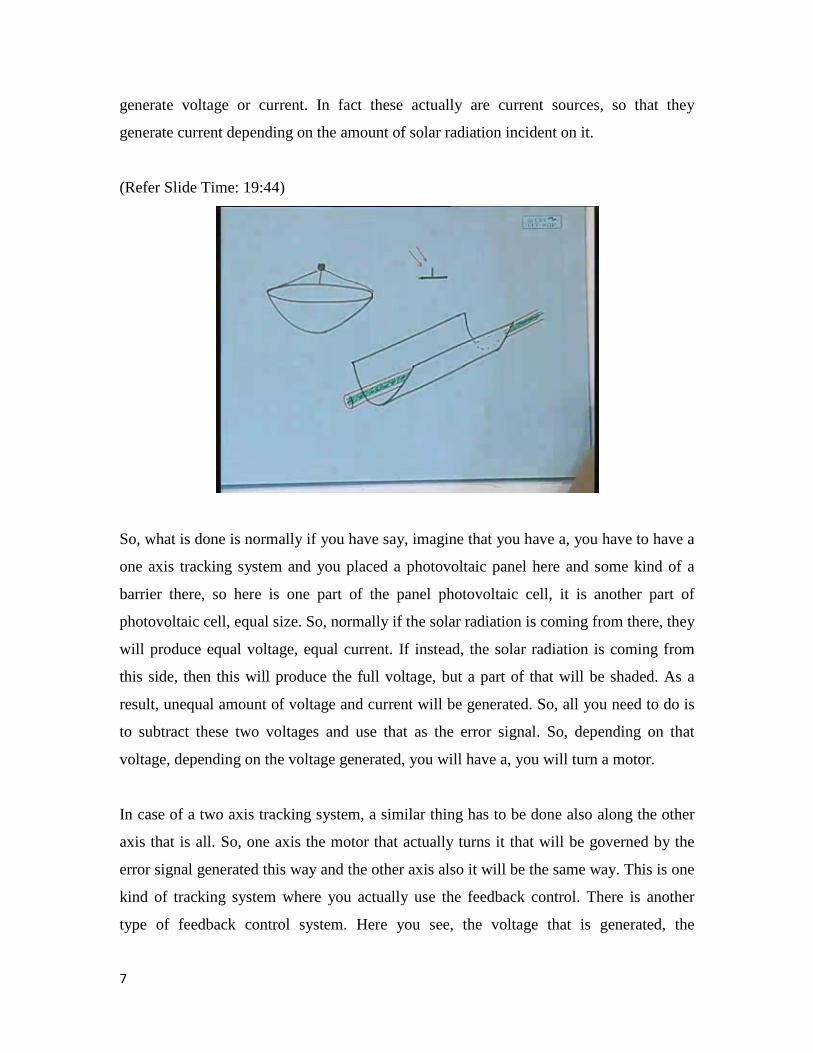
(Refer Slide Time: 26:29)
9
So, there are essentially two types of tracking systems, closed loop and open loop. The
closed loop control system is simpler, does not require a computer. The open loop control
system is more sophisticated, requires the computer, but the performance is guaranteed,
because you will know where the sun will be. So, is there any question regarding these
tracking systems, where you either have a two axis tracking or a single axis tracking and
you either do it by closed loop control or open loop control. Understood, can we go to the
next?
Well, in some situations people nevertheless do not like to have a control system. That
means it has to be a non-tracking system. You have seen that it can be a non-tracking
system, if say it is East West oriented, East West oriented and some seasonal positioning
is done; it can be a non-tracking system. But nevertheless, the problem is that if the
orientation is improper, say the season has passed, but this orientation has not been
changed, what will happen? It will concentrate, but at a point away from the focal plane,
focal line. So, out of the absorber it will not work. So, in some situations, people try to
think of, can we make a reflector which, whose shape will be such that any solar
radiations coming within that area will always be concentrated on to the absorber area
independent of whether I track it or not. In fact, such reflectors do exist.
Let us talk about the geometry of such reflectors. Such reflectors are in general called the
non-imaging concentrators. These were all imaging concentrators, because ultimately the
image of the sun is produced. If you stand in front of that you will see a quite distorted,
but your image; you can identify that it is me, imaging.
10
(Refer Slide Time: 29:01)
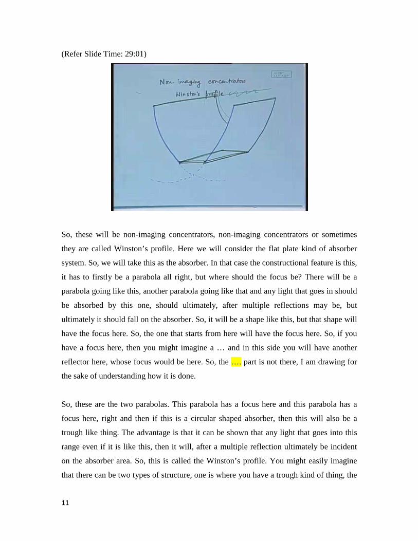
So, these will be non-imaging concentrators, non-imaging concentrators or sometimes
they are called Winston’s profile. Here we will consider the flat plate kind of absorber
system. So, we will take this as the absorber. In that case the constructional feature is this,
it has to firstly be a parabola all right, but where should the focus be? There will be a
parabola going like this, another parabola going like that and any light that goes in should
be absorbed by this one, should ultimately, after multiple reflections may be, but
ultimately it should fall on the absorber. So, it will be a shape like this, but that shape will
have the focus here. So, the one that starts from here will have the focus here. So, if you
have a focus here, then you might imagine a … and in this side you will have another
reflector here, whose focus would be here. So, the …. part is not there, I am drawing for
the sake of understanding how it is done.
So, these are the two parabolas. This parabola has a focus here and this parabola has a
focus here, right and then if this is a circular shaped absorber, then this will also be a
trough like thing. The advantage is that it can be shown that any light that goes into this
range even if it is like this, then it will, after a multiple reflection ultimately be incident
on the absorber area. So, this is called the Winston’s profile. You might easily imagine
that there can be two types of structure, one is where you have a trough kind of thing, the
11
other is where you have, sorry, this is wrong; okay, that is also possible. So, this will then
be a, this will then be a flat plate which will retain all this specialties of the flat plate
collector, except that it will have a larger concentration and therefore larger temperature
rise.
So, there are two possibilities. Either you have a three dimensional trough like structure
or again linear parabolic concentrator, but a non-imaging parabolic concentrator, so that
all the light that enters goes in. You might possibly argue that in that case it is not
necessary to have any tracking.
(Refer Slide Time: 33:24)
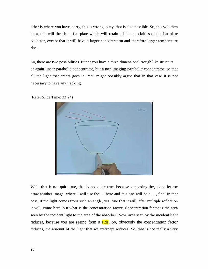
Well, that is not quite true, that is not quite true, because supposing the, okay, let me
draw another image, where I will use the … here and this one will be a …, fine. In that
case, if the light comes from such an angle, yes, true that it will, after multiple reflection
it will, come here, but what is the concentration factor. Concentration factor is the area
seen by the incident light to the area of the absorber. Now, area seen by the incident light
reduces, because you are seeing from a side. So, obviously the concentration factor
reduces, the amount of the light that we intercept reduces. So, that is not really a very
12
clever idea. So, simply making it and keeping it just like that will not help. It has to be
oriented, but in that case it becomes more logical to orient it, if you have a linear one.
(Refer Slide Time: 34:33)
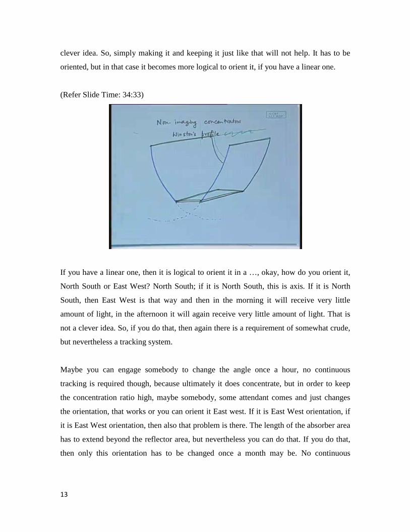
If you have a linear one, then it is logical to orient it in a …, okay, how do you orient it,
North South or East West? North South; if it is North South, this is axis. If it is North
South, then East West is that way and then in the morning it will receive very little
amount of light, in the afternoon it will again receive very little amount of light. That is
not a clever idea. So, if you do that, then again there is a requirement of somewhat crude,
but nevertheless a tracking system.
Maybe you can engage somebody to change the angle once a hour, no continuous
tracking is required though, because ultimately it does concentrate, but in order to keep
the concentration ratio high, maybe somebody, some attendant comes and just changes
the orientation, that works or you can orient it East west. If it is East West orientation, if
it is East West orientation, then also that problem is there. The length of the absorber area
has to extend beyond the reflector area, but nevertheless you can do that. If you do that,
then only this orientation has to be changed once a month may be. No continuous
13
tracking is required in either case. That is why in many situations, this kind of structure is
preferred. But again, how to make, how to make?
Making this often poses a problem. You have these days’ industrial methods of producing
parabolic troughs, because all the TV antennas, the ones that you use in the, the service
providers use, that is basically this type. So, same kind of technology can be used in order
to make this. But, how to make this kind of a reflector, parabolic reflector with, you
know, it is a truncated parabola. You focus somewhere here, so that sometimes poses a
engineering challenge, how to produce a manufacturing system that will manufacture this
kind of thing? But nevertheless, the concept is clear, right. Is the concept clear, the
geometry clear? So, tracking is done, non-tracking concentrators I have done; these are
the non-imaging concentrators, you do not see the image of the sun.
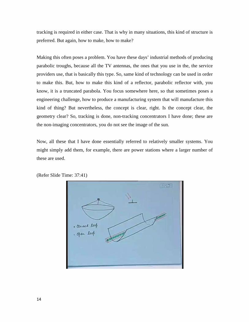
Now, all these that I have done essentially referred to relatively smaller systems. You
might simply add them, for example, there are power stations where a larger number of
these are used.
(Refer Slide Time: 37:41)
14
That means the water comes, goes through one and at a higher temperature goes into
another; it comes out at a higher temperature; finally it goes into steam and you can use
that steam to generate power. So, there are, simply by multiplying this kind of linear
parabolic reflectors, you can have a larger amount of collection and generation of energy.
But, most of the solar thermal power stations, where your objective is not just to generate
steam, hot water or something like that, rather to generate electricity, there you need to
have a larger size.
(Refer Slide Time: 38:27)
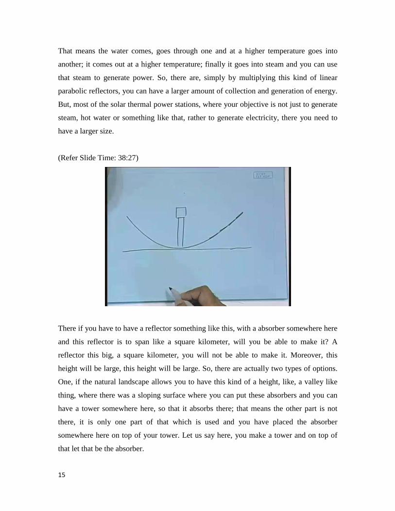
There if you have to have a reflector something like this, with a absorber somewhere here
and this reflector is to span like a square kilometer, will you be able to make it? A
reflector this big, a square kilometer, you will not be able to make it. Moreover, this
height will be large, this height will be large. So, there are actually two types of options.
One, if the natural landscape allows you to have this kind of a height, like, a valley like
thing, where there was a sloping surface where you can put these absorbers and you can
have a tower somewhere here, so that it absorbs there; that means the other part is not
there, it is only one part of that which is used and you have placed the absorber
somewhere here on top of your tower. Let us say here, you make a tower and on top of
that let that be the absorber.
15
Such a power station has in fact been installed in Spain, but it is not difficult to see that
such locations are rare, a location where this slope will be facing South, more or less a
flat surface that can be oriented like this, very rare. So, something else has to be done in
order to make this kind of a thing. So, what is the actual challenge? The actual challenge
is that you need to have, if it is a reflector that spans over a square kilometer, it has to rise
for a larger, large length. Secondly, you cannot really make a single reflector like that, it
will be practically impossible. So, what to do? You can of course break it up like one
here, another here, another here, another here and so on and so forth, but still the problem
is that you have to elevate.
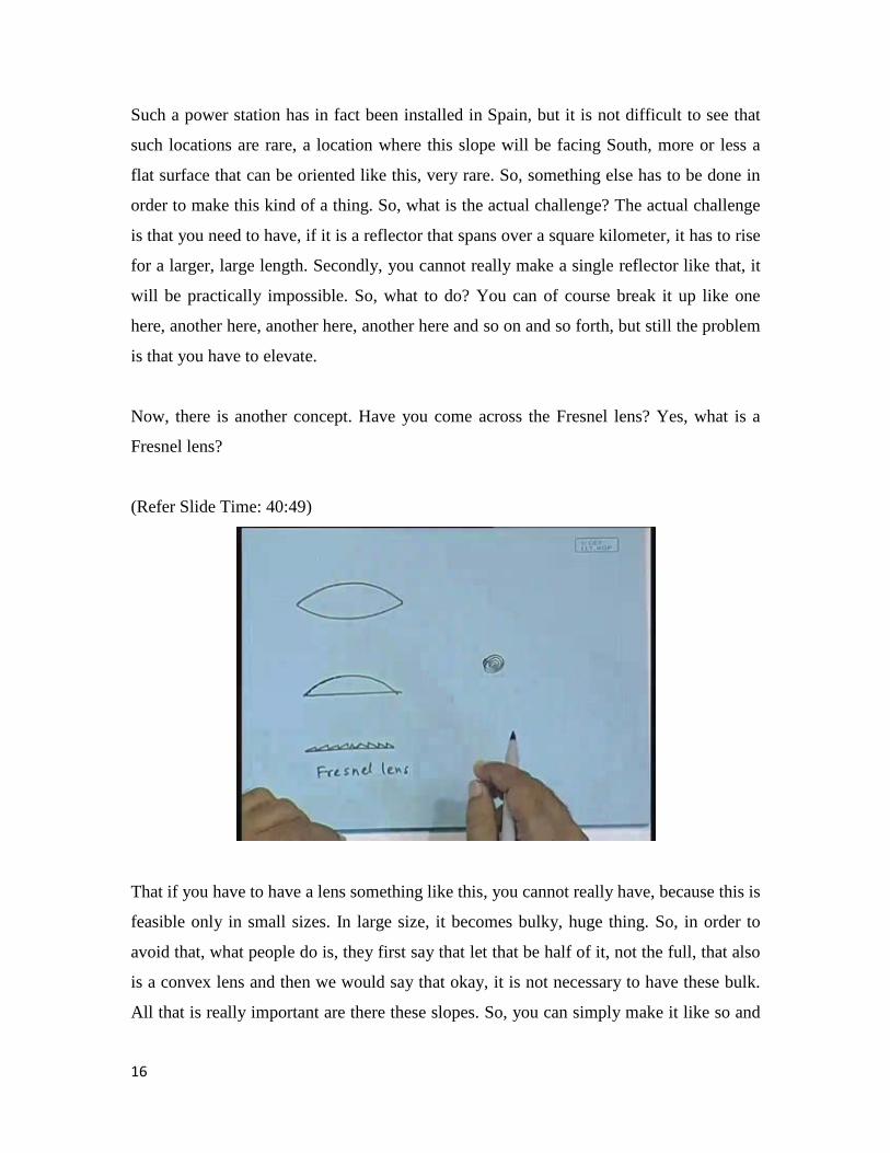
Now, there is another concept. Have you come across the Fresnel lens? Yes, what is a
Fresnel lens?
(Refer Slide Time: 40:49)
That if you have to have a lens something like this, you cannot really have, because this is
feasible only in small sizes. In large size, it becomes bulky, huge thing. So, in order to
avoid that, what people do is, they first say that let that be half of it, not the full, that also
is a convex lens and then we would say that okay, it is not necessary to have these bulk.
All that is really important are there these slopes. So, you can simply make it like so and
16
that is how you make the Fresnel lens. So, this is called the idea of the … It is not
pronounced as Fresnel, it is pronounced as Frenel, though the spelling is Fresnel. So, you
have to have a, have you seen these lenses? No, you have only read in a book, concepts.
Have you seen those overhead projectors, over overhead projectors where you use a
transparency and that is projected onto the screen, so in that, in the seminar rooms …
Students: Yes.
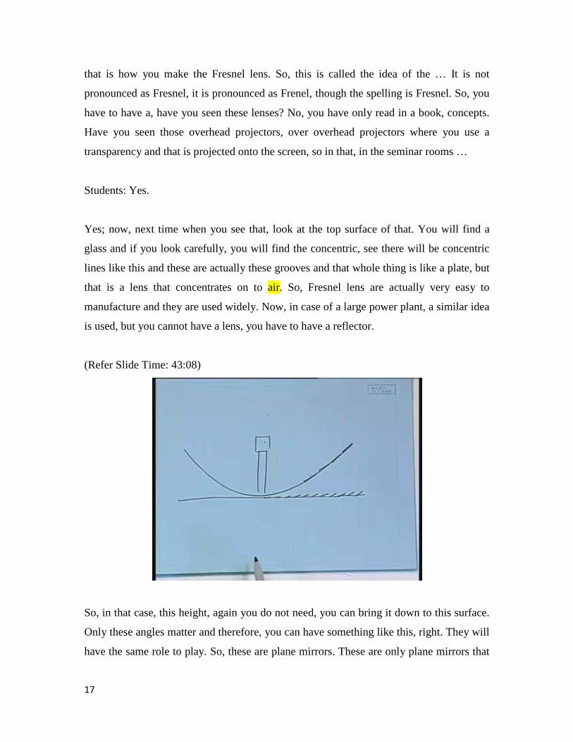
Yes; now, next time when you see that, look at the top surface of that. You will find a
glass and if you look carefully, you will find the concentric, see there will be concentric
lines like this and these are actually these grooves and that whole thing is like a plate, but
that is a lens that concentrates on to air. So, Fresnel lens are actually very easy to
manufacture and they are used widely. Now, in case of a large power plant, a similar idea
is used, but you cannot have a lens, you have to have a reflector.
(Refer Slide Time: 43:08)
So, in that case, this height, again you do not need, you can bring it down to this surface.
Only these angles matter and therefore, you can have something like this, right. They will
have the same role to play. So, these are plane mirrors. These are only plane mirrors that
17
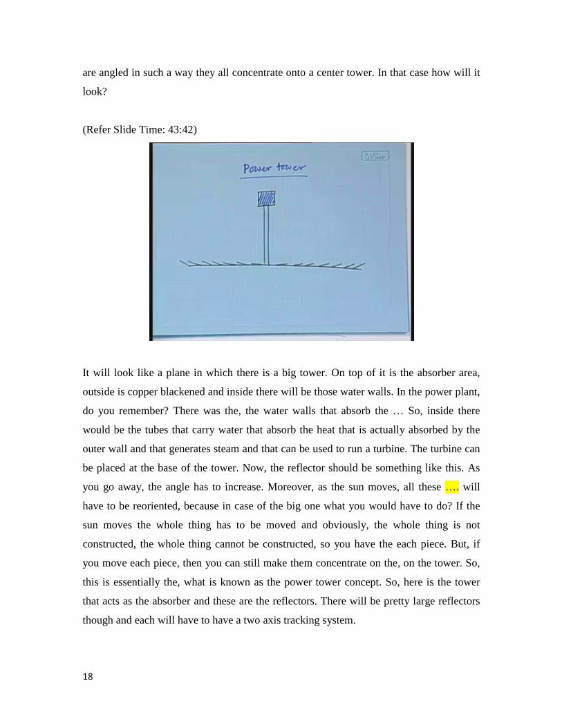
are angled in such a way they all concentrate onto a center tower. In that case how will it
look?
(Refer Slide Time: 43:42)
It will look like a plane in which there is a big tower. On top of it is the absorber area,
outside is copper blackened and inside there will be those water walls. In the power plant,
do you remember? There was the, the water walls that absorb the … So, inside there
would be the tubes that carry water that absorb the heat that is actually absorbed by the
outer wall and that generates steam and that can be used to run a turbine. The turbine can
be placed at the base of the tower. Now, the reflector should be something like this. As
you go away, the angle has to increase. Moreover, as the sun moves, all these …. will
have to be reoriented, because in case of the big one what you would have to do? If the
sun moves the whole thing has to be moved and obviously, the whole thing is not
constructed, the whole thing cannot be constructed, so you have the each piece. But, if
you move each piece, then you can still make them concentrate on the, on the tower. So,
this is essentially the, what is known as the power tower concept. So, here is the tower
that acts as the absorber and these are the reflectors. There will be pretty large reflectors
though and each will have to have a two axis tracking system.
18
Normally, these tracking systems, in such systems, it is never a feedback control system.
It is always that you know the position of the sun and that gives a signal as to how to
orient these individual reflectors and such systems have been installed with reasonably
large capacity like 100 megawatt or so, essentially in desert areas, because that requires
to cover a large amount of area, desert areas and that has, even though the installation
cost is at present quite high, so it does not really compete with the existing fossil fuelled
power plants.
Why is the installation cost high? Mainly because these reflectors, you know, reflectors
as big as this room, each will be and that has to be, has to have a two axis tracking
system, that has to stand on a platform that will make it withstand winds, windstorms, so
that has to have a have a reasonably good structure and that increases the overall cost of
the system. Moreover, mirrors, it themselves are pretty expensive; shiny steel surface,
they are themselves pretty expensive. So, this is the concept of the power tower. In India,
we do not have any of them yet, any of the power towers yet, but there are power towers.
As I told you, a one sided power tower where you have a mountain, is installed in Spain.
There are a couple of such power towers in USA. Europe does not have so much
sunshine, so they did not go for this kind of a system, but it is basically the temperate
areas like ours that may benefit from this kind of a concept. But as yet, as I told you, the
technology is not matured enough to make them economically competitive with the rest
of the fossil fuel systems.
19
(Refer Slide Time: 47:40)
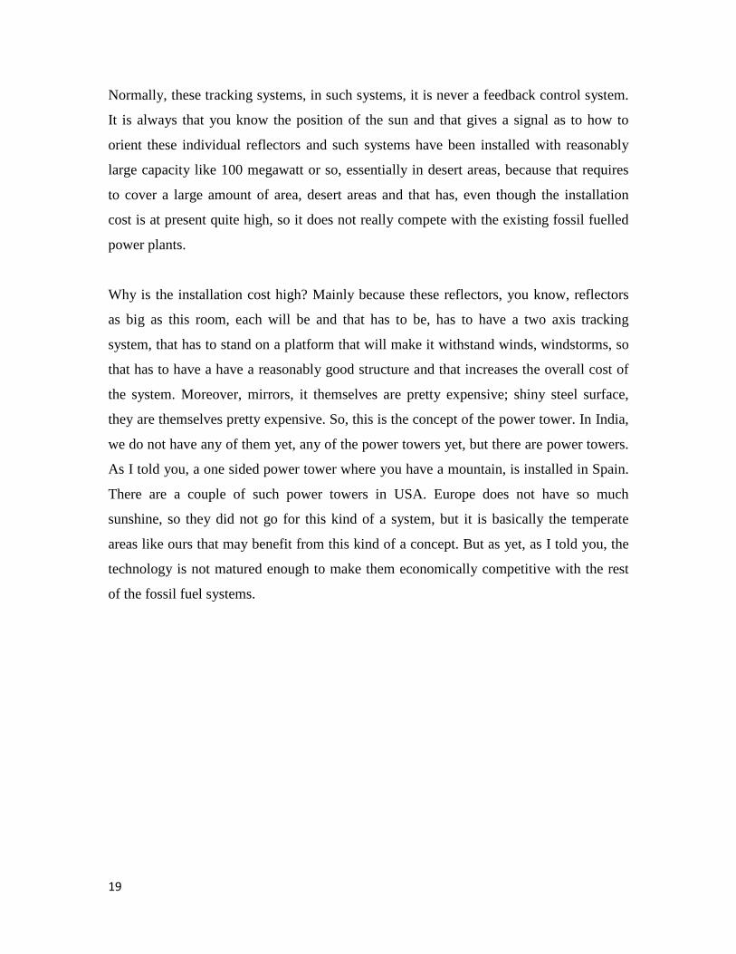
These are pictures of the things that we talked about on the computer screen. Right now,
you see the picture of a whole power plant made of linear parabolic concentrators. These
are the linear parabolic concentrators. Do you see the size? Here are the people standing
and in comparison to that you can see the size of this linear parabolic concentrators and
on the focal line you can see this absorber tube going. So, these are the absorber tubes
that go along the focal line and you can see that whole field is covered with such
collectors, concentrating collectors, as a result of which the total amount of energy
collected is large, sufficient to produce steam and thence to produce electricity. Let us see
another picture. This one is not all that good though. Let us see this one.
20

(Refer Slide Time: 48:51)
So, here also you see another picture; I will put it in a slightly lower size, yes. Here are
the similar large arrays of linear parabolic concentrators with these are the tubes that are
going. As I told you in the class that these can either be aligned North South or East
West, depending on the facilities for tracking that are available. I do not know what these
particular power plants operate on, but now let us look at some of the power towers.
(Refer Slide Time: 49:29)
21
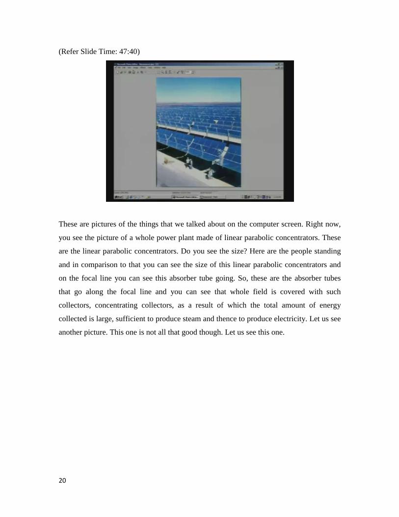
Here is a, here is a power tower. You can see that these are the reflectors. These are
standard flat reflectors, but very large in size. At the middle there is the tower and on top
of it there is this absorber area. So, all these reflectors reflect onto this absorber area and
you can see that this is a desert area in which this power station has been installed,
thereby utilizing an otherwise completely unusable tract of land.
(Refer Slide Time: 50:15)
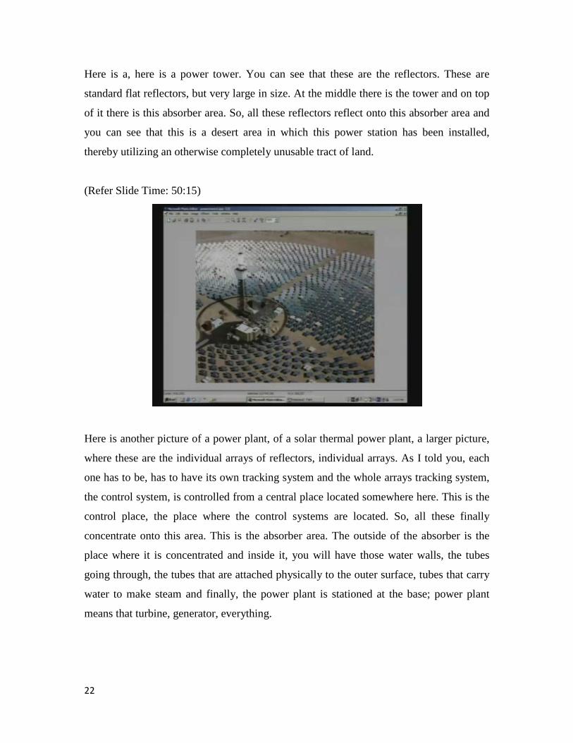
Here is another picture of a power plant, of a solar thermal power plant, a larger picture,
where these are the individual arrays of reflectors, individual arrays. As I told you, each
one has to be, has to have its own tracking system and the whole arrays tracking system,
the control system, is controlled from a central place located somewhere here. This is the
control place, the place where the control systems are located. So, all these finally
concentrate onto this area. This is the absorber area. The outside of the absorber is the
place where it is concentrated and inside it, you will have those water walls, the tubes
going through, the tubes that are attached physically to the outer surface, tubes that carry
water to make steam and finally, the power plant is stationed at the base; power plant
means that turbine, generator, everything.
22
(Refer Slide Time: 51:27)
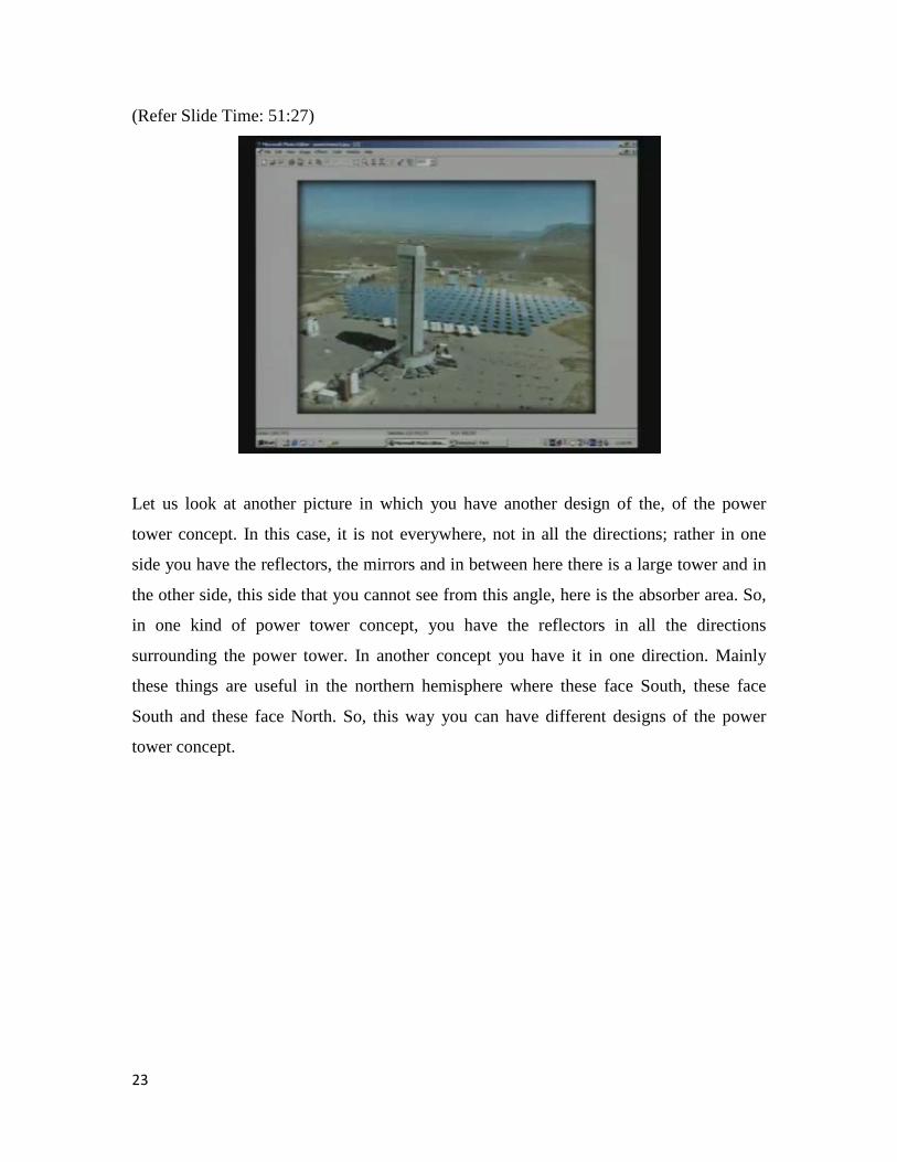
Let us look at another picture in which you have another design of the, of the power
tower concept. In this case, it is not everywhere, not in all the directions; rather in one
side you have the reflectors, the mirrors and in between here there is a large tower and in
the other side, this side that you cannot see from this angle, here is the absorber area. So,
in one kind of power tower concept, you have the reflectors in all the directions
surrounding the power tower. In another concept you have it in one direction. Mainly
these things are useful in the northern hemisphere where these face South, these face
South and these face North. So, this way you can have different designs of the power
tower concept.
23
(Refer Slide Time: 52:22)
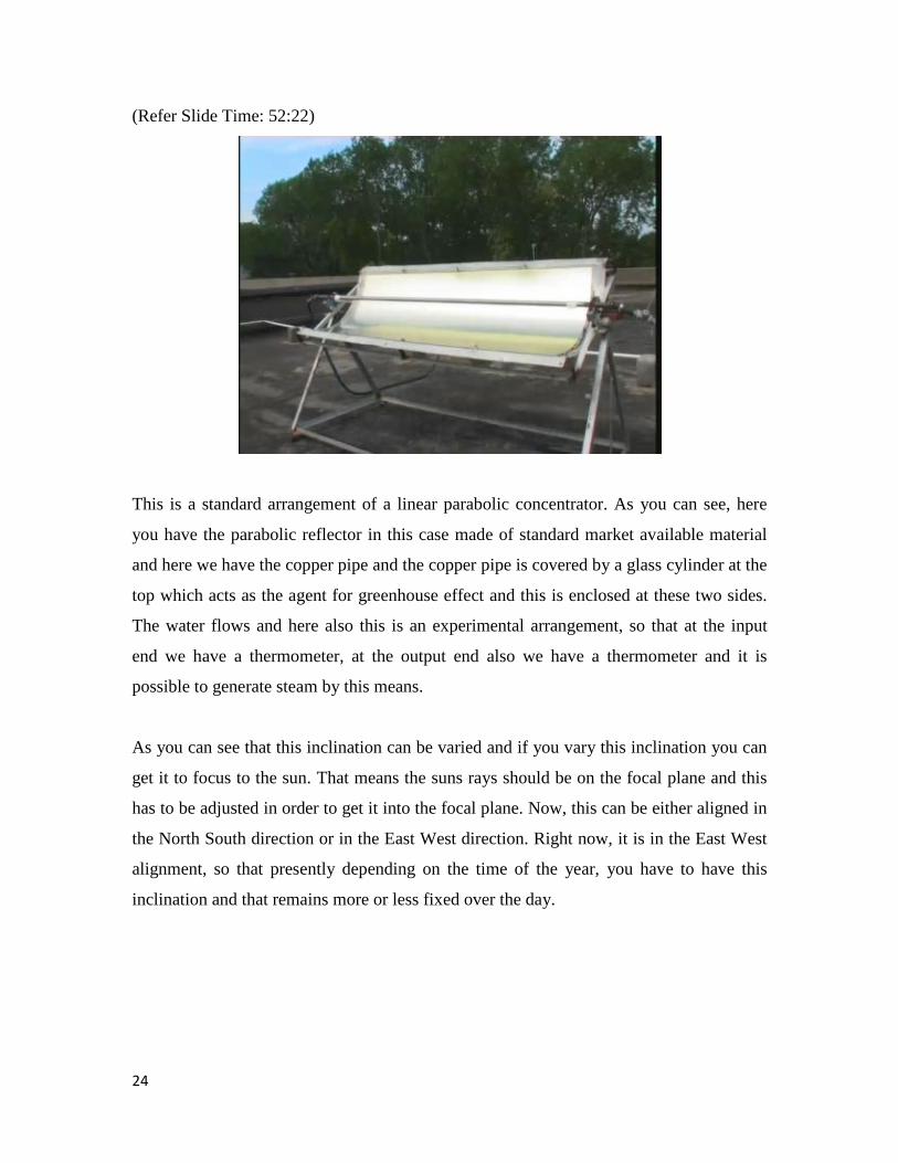
This is a standard arrangement of a linear parabolic concentrator. As you can see, here
you have the parabolic reflector in this case made of standard market available material
and here we have the copper pipe and the copper pipe is covered by a glass cylinder at the
top which acts as the agent for greenhouse effect and this is enclosed at these two sides.
The water flows and here also this is an experimental arrangement, so that at the input
end we have a thermometer, at the output end also we have a thermometer and it is
possible to generate steam by this means.
As you can see that this inclination can be varied and if you vary this inclination you can
get it to focus to the sun. That means the suns rays should be on the focal plane and this
has to be adjusted in order to get it into the focal plane. Now, this can be either aligned in
the North South direction or in the East West direction. Right now, it is in the East West
alignment, so that presently depending on the time of the year, you have to have this
inclination and that remains more or less fixed over the day.
24


![Lec16[1]Integrales Linea](https://img.pdfslide.net/doc/110x75/577cd54f1a28ab9e789a7098/lec161integrales-linea.jpg)