Embed Size (px)
Citation preview
Accepted ___.___._____ __________________________________
Energy Saving of Central Air-Conditioning and Control System
Caseb Study: Nanchang Hongkelong Supermarket
Thesis
Yizhou He
Degree Programme in Industrial Management
SAVONIA UNIVERSITY OF APPLIED SCIENCES, BUSINESS AND ENGINEERING, VARKAUS
Degree Programme
Industrial Engineering and Management
Author
He Yizhou
Title of Project
Energy saving of central air-conditioning and control system
Case study: Nanchang Hongkelong Supermarket
Type of Project Date Pages
Final Project 13/10/2010 62+8
Academic Supervisor Company Supervisor Company
Harri Heikura Zheng Jun HKLS
Abstract
In China, with the rapid development of economiy, the resources are consumed very seriously.
Compared with the developed countries, China’s energy consumption for unit GDP production is more
than 6 to 10 times and the energy consumption for unit product production is 50% higher than in the
developed countries. Therefore, China is increasing emphasis on energy conservation and is also
increasing the awareness of energy saving and environmental protection.
In energy saving measures, the one that reduces energy consumption of the central air conditioning is
very important. Because in industrial and commercial buildings, central air conditioning system is a very
important part of infrastructure and it is widely used. It takes a large proportion in industrial production
and the total daily energy consumption of buildings. In industry, central air-conditioning energy
consumption accounts for over 40% of the total energy consumption.
In this thesis, the problem and the cause of the problem were found according to the research of the
specific practical problem of the traditional energy saving system. Based on the theory of intelligent
building management system (IBMS) and energy-saving central air-conditioning inverter, a means of
vector control can be adopted to achieve the integrated use of the technology and a solution to improve
the Central Air Conditioner equipment and improve HVAC energy saving control system can be found.
In this thesis, it was studied how to reduce the central air-conditioning energy consumption, and also it
was a case study about improvement of Nanchang HKLS air conditioning system. This case study shows
the practical design and practical improvement of the project can be known and it is also shown the
energy saving result by economic analysis is also presented.
Keywords
Central Air Conditioning, HVAC, Energy Saving, CACS, Inverter
Confidentiality

CONTENTS
1 Introduction ...................................................................................................................... 3
2 The status and development of the energy saving of HVAC system ............................... 5
2.1 Background ........................................................................................................... 5
2.2 The characteristic and problem of HVAC system ................................................. 6
2.3 The energy saving measures of HVAC ................................................................. 8
2.3.1 The energy-saving by architecture design .................................................. 9
2.3.2 Measures to decrease air standards ............................................................ 9
2.3.3 Energy saving measures of HVAC system ............................................... 10
2.4 The principle and application of frequency conversion adjustment .................... 13
2.4.1 The basic principle of frequency converter .............................................. 13
2.4.2 Functions of variable frequency speed control ........................................ 13
3 Development and Testing of HVAC Control System ..................................................... 19
3.1 Structural design of control system ..................................................................... 19
3.2 The function of control system ............................................................................ 21
3.3 Software design ................................................................................................... 25
3.3.1 Embedded real-time operating system ..................................................... 25
3.3.2 Control flow’s design based on RTOS ..................................................... 26
3.4 Hardware design .................................................................................................. 28
3.4.1 Node controller ......................................................................................... 28
3.4.2 The design of equipment room server ...................................................... 31
4 Research on energy saving of central air conditioning system in Nanchang
HongKeLong Supermarket (HKLS) ............................................................................. 35
4.1 Calculation condition .......................................................................................... 35
4.1.1 Calculation of meteorological parameters ................................................ 35
4.1.2 The scope and requirement of the design ................................................. 35
4.2 Preliminary design ............................................................................................... 36
4.2.1 Purification of air conditioning system design ......................................... 37
4.2.2 Cold water system design ......................................................................... 39

4.2.3 The control sequence of air conditioning system ..................................... 39
4.2.4 Noise elimination and shockproof method ............................................... 40
4.3 The equipment selection of air-conditioning and cold and heat source .............. 40
4.3.1 Air handling equipment selection ............................................................. 40
4.3.2 Cold and heat source selection ................................................................. 42
4.4 Automatic Control on Air-conditioning and Cooling/Heating source system .... 42
4.4.1 Automatic control of fan in air conditioning unit ..................................... 42
4.4.2 Automatic control of water system ........................................................... 43
4.4.3 The automatic control and operation of basement smoke exhaust system44
5 Improvement Project Program for Energy Saving in Central Air Conditioning System in
Nanchang HKLS .......................................................................................................... 46
5.1 Equipment overview ........................................................................................... 47
5.2 Improvement plan ............................................................................................... 48
5.2.1 The equipment of improvement plan for energy saving .......................... 48
5.2.2 Specific measure ...................................................................................... 49
5.3 Technical feature ................................................................................................. 50
5.4 Technical and economic analysis ........................................................................ 51
6 Conclusions .................................................................................................................... 54
References ......................................................................................................................... 55
Abbreviations .................................................................................................................... 59
Appendices ........................................................................................................................ 62

3
1 Introduction
Because of worldwide energy crisis, the construction of industry development has brought
a great impact. There are increasingly widespread attention for the rational use of energy
and new energy development. [1]
In China, with the rapid development of economic situation, the resources are consumed
very seriously. Compared with the developed countries, China’s energy consumption for
unit GDP production is more than 6 to 10 times and the energy consumption for unit
product production is 50 % higher than in the developed countries. Therefore, China is
increasing emphasis on energy conservation and is also increasing the awareness of energy
saving and environmental protection. Saving energy, reducing production and office costs
become one of the main ways to improve the market competitiveness in many enterprises.
[1]
In energy saving measures, the one that reduces energy consumption of the central air
conditioning is important. To improve the living environment, there are many places such
as apartments, villas and residential areas that have begun to use the central
air-conditioning. Especially more and more central air-conditioning systems are installed
in commercial office buildings, factories, supermarkets and other built-up areas. In
industrial and commercial buildings, central air conditioning system is a very important
part of infrastructure and is widely used. It takes a large share in industrial production and
the total daily energy consumption of buildings. In industry, central air-conditioning energy
consumption accounts for over 40% of the total energy consumption. In commercial
buildings, the mechanical and electrical equipment and lighting take more than 80 % of
energy consumption, and central air-conditioning energy consumption has accounted for
about 60 % of this energy consumption. [1]
How to reduce the central air-conditioning energy consumption but still ensuring a
comfortable environment has become an issue which is focused by both scientists and

4
engineers. So, around the world, there a lot of manpower, material and financial resources
are put to research the energy-saving buildings and higher requirement for energy
conservation of the building HVAC system are also put forward. Also this is a main focus
of this thesis. [1]

5
2 The status and development of the energy saving of HVAC system
Because of great economic and social benefits, central air-conditioning energy-saving
technology has more and more widespread attention. The central air-conditioning
energy-saving technology is studied by many companies and scientific research workers
and it has experienced a number of technical innovations. [2]
2.1 Background
The first-generation of energy-saving technology [2]
The main way that the first generation of energy-saving technology is reforming the
energy-saving system of central air-conditioning water pump is by using frequency
conversion control technology which makes a single pressure or temperature control. With
the pressure control, it increase 10 % to 30 % energy-saving; with the temperature control,
it increases 40 % energy-saving. It usually accounts for 5 %~10 % in the whole
energy-saving of central air conditioning system.
The second-generation of energy-saving technology [2]
The second-generation of energy-saving technology has the intelligent control on the basic
of traditional inverter technology which is using advanced computer software processing,
modular control with inverter technology and the collection and processing of multi-point
technology. This way the control system can keep pace with changes in temperature and
can have dynamic adjustment of the actual load. Then main unit of air conditioner can
reach 10 %-30 % energy saving and water system can reach 60 %-80 % energy saving.
Thus, it reaches about 20 %-40 % energy saving in the whole machine system.
6
Starting from the second-generation technology, control software processing has become
the core technology of energy saving system. There are many new technologies which are
applied to the energy-saving device in a wide range such as an expert system, a fuzzy
system and an optimized control. The core module for control, which is suited for the
actual needs, becomes a key of research and implements the technology of central
air-conditioning energy-saving. The traditional PID only applies to single-variable linear
control system and is powerless for multi-variable and multi-disturbance of central
air-conditioning unit control system.
There is also another development direction for central air-conditioning energy saving
which is used in variable flow control in the central air-conditioning system. During
operation of variable flow system, the flow is controlled by adjustment of PID parameter
and set pressure technology. The flow loop of various branches changes in the load of
external environment change. This does not only ensures the comfort of air-conditioning
system, but also achieves purposes of energy-saving.
The third-generation of energy-saving technology [2]
Based on the second-generation of energy-saving control system, the third-generation
technology uses to transform the whole central air-conditioning by air-conditioning
refrigerant replacement, fan-coil cleaning, add anti-wear agent, etc. When the variable
frequency control system is selected to optimize the system, the whole central
air-conditioning can reached 25 %-50 % energy saving. Now it is the newest energy-saving
research direction.
2.2 The characteristic and problem of HVAC system
Central air-conditioning which is a complex system composed by a large number of
components, and the various components are often distributed throughout the entire

7
building. If the system wants to work out the capacity of adjust air to protect the indoor
environment, the components must work together effectively. So the central
air-conditioning system control is very important. [3]
The main features of central air-conditioning system are [3]:
Multiple interferential
The function of air-conditioning system keeps the indoor environment suitable. Because of
the impact of the solar radiation, the outdoor and indoor’s air heat, and the heat dissipation
of the indoor personnel, the air-conditioning system is multiple interferential.
Control object diversity
There are many factors that affect the air-conditioning in the indoor environment. Also it
will be used in various environment because the different status of architectural forms and
uses of conditions.
Control variable relativity
Generally, the control variable of air-conditioning system is the room temperature and
humidity. The system often adjusts these two control variables at the same time. But these
two parameters are restrained and influencing each other. Adjusting the temperature will
change the saturation of partial pressure of the steam in the air. This will change the relative
humidity in indoor; this is because when humidity is adjusted, the surface will be cooling
and desiccant, or spray water and steam to cause humidification, so the air temperature will
be changed.

8
Object variability
The normal air-conditioning system has two kinds of operating conditions in summer and
winter, and the requirement of the object and working principle are different in these two
kinds of operating conditions. Because of these features, not only the air-conditioning
control system often seems complex, but also the air-conditioning control system is
diversified. So the air-conditioning control system develops and progresses by continuous
research and engineering practice.
The main problems of central air-conditioning system are [3]:
The system efficiency is not high because of the design margin of central
air-conditioning system overload.
Because the layout of the system is not reasonable, it increases the resistance of the
system and energy consumption.
There are poor control of operation and lack of effective energy management.
2.3 The energy saving measures of HVAC
The measures of air-conditioning energy-saving system can be divided into three areas:
The energy-saving by architectural design. It is an energy-saving idea which is a way
of reducing energy sources.
The energy-saving measures, which regulate the quality of the air-conditioning by
reducing the cooling load demand.

9
Energy-saving measure of central air-conditioning. The energy-saving idea is to
improve the efficiency of the whole system by improving the design of central air
conditioning and the coordination of controlling the devices.
2.3.1 The energy-saving by architecture design
The building air-conditioning load is mainly affected by the impact of construction
conditions. Thus to achieve energy-saving of air-conditioning system, firstly the building
should be made energy efficient and air conditioning load. In the energy-saving of
architecture design, there are several main aspects which are presented in the following:
The heat transfer coefficient of exterior protected construction should meet the
requirements of the relevant standards. Then it can be used to improve heat-insulating
property of the structure of building and be used to use of thermal insulation materials.
An air-conditioned building should avoid east-west position as much as possible. Also
the surface area should be reduced and the light-colored surface should be used.
The air-conditioned room, where temperature and humidity are required similar,
should focus on the layout. An air-conditioned room should be avoided at the top of
building. When it has to be located at the top, the roof should have good thermal
insulation measures.
The anti-infiltration facility is needed when the outer door is opened frequently.
2.3.2 Measures to decrease air standards
The energy consumption of a system is higher if the indoor temperature and relative
humidity is lower in summer or the indoor temperature and relative humidity is higher in

10
winter. Accounting to the data, if the indoor temperature is changed from 24 ℃to 28 ℃ in
summer, the cooling load can be reduced 36 %. If the indoor temperature is changed from
22 ℃ to 18 ℃ in winter, the heat load can be reduced about 55 %. Thus, in order to save
energy consumption, the indoor temperature and humidity, which can meet requirements
of production and human health and comfort, should be as high as possible in summer
and as low as possible in winter.
2.3.3 Energy saving measures of HVAC system
1. The selection of equipment should be appropriate and energy efficient products should
be used. The flow of pump and the volume and air pressure of fan should be
compatible with the requirement of system.
2. It is needed to improve the system’s construction quality and minimize the water and
air leakage in the piping system. Also it is needed to strengthen the insulation and
reduce the loss of cooling capacity in the transmission.
3. The reasonable control and the use of the outdoor fresh air in a right way are some of
the most effective energy-saving measures. In the case of the air-conditioned room
which needs cooling in summer and heating in winter, if the outdoor fresh air volume
is higher, the energy consumption is higher. In this case, the outdoor fresh air should be
controlled to reach the minimum requirement for health. In winter, when indoors it is
needed to provide cold wind, it should make full use of outdoor cooling air. By using
all outdoor air, it can delay time of using the artificial cold source and save cold source
energy consumption.
4. Consumption of conveying system should be reduced. Increasing pipe size and
minimizing elbow valve can reduce the resistance of the air and water in the process of
conveying, and then increasing the temperature difference of air and temperature

11
difference of water supply and backwater can reduce the flow of water. Both of them
can greatly reduce energy consumption of conveying system.
5. One more measure is to use heat recovery technology. Air heat recovery equipment
has two types which are sensible heat recovery equipment and total heat recovery
equipment, and it is mainly used for recycling the consumption of discharge air in air
conditioning system and directly passed to the fresh air. Heat recovery equipment can
be individually set in the air discharging system of air conditioning, which can also be
a function of modular air conditioning unit. It usually can save air load about 70 %.
It is needed to make sure that the automatic operation and management of air conditioning
system. Ensure not only the air-conditioned room’s temperature, humidity accuracy and
savings in manpower, but also are an important part to preventing the loss of air
conditioning system loss and saving energy. There are several main aspects:
1. Control of the indoor temperature and humidity: regulating the heat of air conditioning
system, changing the cold (hot) water of fan coil and changing the fan speed to control
room temperature. Similarly, changing the cooling water of coil, adjusting links for
backwater valve and changing the mixing ratio of fresh return air can control the
indoor relative humidity. If the room temperature or indoor relative humidity are not
be controlled, it will appear too cold and dry in summer and too hot and wet in winter,
and result in excessive consumption of energy.
2. Control of the best start and stop time: for intermittent operation of the air conditioning
system, when the air conditioning stops running, the indoor air temperature changes
and exterior protected construction retains a certain amount of heat storage capacity or
cold. Before the room is used again, it is needed to adjust indoor temperature in a given
value, and then there must advance give into the room more than the design condition
for the load of cold (hot) of the cold (thermal) capacity allows. According to the
temperature changing rule after the air conditioning stops running, it can obtain the

12
first downtime of refrigerating machine to maintain the room temperature in the
minimum requirement.
3. Control air conditioning system running by microprocessor: a microprocessor is used
to automatically control the operation of air conditioning system. Mainly by the
microprocessor through the forecast the indoor and outdoor air state parameters, this is
in order to minimize energy consumption as the basic evaluation function by
maintaining comfortable indoor environment as constraint conditions. And according
to the size of air conditioning load to judge and determine the cooling (heating)
capacity number, command of operating units number (such as cold (hot) source unit,
water pumps and fans), working methods and operating cycle.
The first method is the “root cause” to consider central air conditioning energy
conservation. Starting from the source to stop the cooling load waste of the central air
conditioning and to reduce the cooling load in the room, it can greatly reduce the cooling
load demand and have more obvious energy saving effect. But it needs to involve a very
wide range and is difficult achieve currently in China.
The second method can reduce central air conditioning energy consumption to some extent,
but it is only do in the work on the “surface” and can not solve the intrinsic problem of the
central air conditioning.
The third method is to consider central air conditioning energy conservation based on the
system. Through controlling the reasonable operation of the central air conditioning, it can
better solve the problems of central air conditioning and is a very practical way.

13
2.4 The principle and application of frequency conversion adjustment
This chapter introduces how the frequency converter operates. It also introduces where
the frequency converter can be used and how it can be used.
2.4.1 The basic principle of frequency converter
In the energy-saving renovation of central air conditioning system, conversion technology
plays as an important role. Frequency converter has two forms which are the AC-AC and
the AC-DC-AC. The AC-AC frequency converter can be directly converted AC into AC
which voltage and frequency can be adjusted. It is also called as a direct converter. The
AC-DC-AC frequency converter is first converting power frequency AC into DC, and then
converting DC into AC which voltage and frequency can be adjusted. It is also known as
indirect frequency converter. [4]
2.4.2 Functions of variable frequency speed control
1. Frequency energy-saving function
The capacity of frozen pump motor is designed in accordance with maximum amount of
heat exchange in the hottest day. Due to temperature changes in seasonal and diurnal,
environmental and climatic differences and the movement of persons, in fact, heat
exchange is much less than the design value. The amount of heat exchange is controlled by
the freezing water flow, and the flow of freezing water is controlled by the motor speed of
frozen pump. [5]
But electric power consumption of motor is controlled by its output power, output power P
is proportional to the cube of the motor speed n (P ∝ n3), and the motor speed n is
proportional to the power supply frequency f (n ∝ f). So the motor speed decreased slightly,

14
that is slightly reduce power supply frequency and output power will be significantly
decreased. If the motor speed can be adjusted by the heat exchange capacity of actual need,
electrical power will be greatly reduced and thereby it is significantly saving energy. [5]
2. Soft start and stop function
When motor is started directly or Y/D start, the starting current is equal to 3-7 times of the
rated current. It will cause serious impact to supply power system and electrical equipment,
also the requirement of power system capability is too high. Start-current and vibration is
extremely unfavorable to the life of the equipment, and when starting and stopping, the
water hammer effect can easily cause pipeline rupture. But by using frequency control
technology, it can be achieved the current started from scratch and the maximum current is
no more than the rated current. This is the real soft start which not only can reduce the
impact and demand of power supply capacity, but also can extend equipment life and
reduced equipment maintenance costs.
3. The theoretical basis of frequency control can be energy saving
According to the basic characteristics of the pump and motor, there is always the following
relationship:
Water flow and pump motor are in direct proportion, Q ∝ P;
Motor shaft power and the cube of pump motor speed are in direct proportion, P ∝ n3;
Pump motor speed and frequency are in direct proportion, n ∝ f;
Pump head and the square of water flow rate are in direct proportion, h ∝ Q2;
Pipeline resistance is proportional to the cube of velocity, Z ∝ v3;
Therefore, it can change the frequency to reduce the pump motor power to suit the changes
in water flow. [6]

15
4. The components of variable frequency energy-saving system of central air
conditioning
The variable frequency energy-saving system of central air conditioning needs a
combination of hardware and software technology. It means using of vector control
integrated with the use of the techniques which include dynamic process corresponding
compensation, constant torque regulator and transient suppression. The new products of
frequency conversion technology, which through the synchronous tracking, pressure
regulating, phase modulation, adjust the frequency and transient suppression in one, have
following features: [7]
Control voltage and limit current which under the conditions of constant torque
adjustment can make the motor load in the voltage and current of operating status
which have the most appropriate, the smallest and most economical power.
The optimization frequency modulation technique, which is controlled by vector
control and fuzzy logic, has all the most advanced features of general converter.
Achieve dynamic power factor compensation by the computer track of sample.
Transient flow interference suppression technique filtrates transient flow fluctuations
and reduces the loss and interference.
It is because of these advantages, the central air conditioning frequency energy-saving has
the theoretical basis and the feasibility of implement control.

16
5. The application of frequency technique in the central air conditioning system
Ending the air supply of the inverter control of central air conditioning
In the central air conditioning system, the transmission medium is usually cold or warm
water. The clean air will be fully in contact with the heat exchanger in the air terminal and
the clean air flows directly into the interior by fan to achieve the purpose of regulating
room temperature. When the transport medium (water) temperature is constant, the cold
(heat) of indoor will be changed by changing the air flow, and then the indoor temperature
can be more easily adjusted. This can be set room temperature according to requirements
which are needed. The air flow is controlled by adjusting the fan speed. By using the
converter, fans achieve continuously variable, while in the frequency, the voltage input is
changed also, thus it can save energy, reduce system noise and improve comfortable and
economical use central air conditioning. [8]
The advantages of VAV control are: saving energy significantly with reducing the air
conditioning unit noise, reducing the amount of labor intensity, reducing the impact on
power with soft-start and steady speed of converter. The disadvantage is large investment
costs. [9]
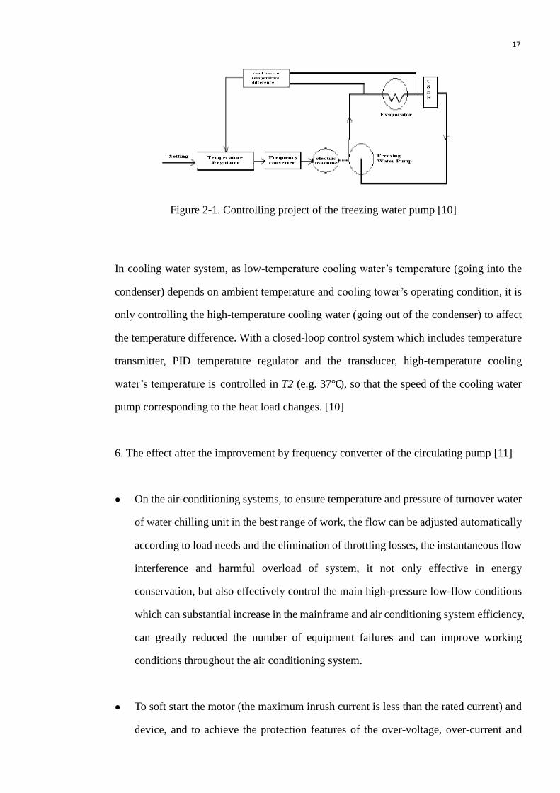
Circulating Pump Frequency Control of central air conditioning [10]
In the freezing water system, the output water temperature depends on the setting of
evaporator and return water temperature depends on the heat load of building. Between
output water temperature and return water temperature, the central air conditioning
freezing water’s maximum design temperature difference is 5℃. As shown in Figure 2-1,
the closed-loop control system is used which includes temperature transmitter, PID
temperature regulator and the transducer on the evaporator outlet pipe and return pipe.
Through the freezing water temperature’s difference (e.g. ΔT = 5℃) the freezing water
pump speed is controlled which can make the corresponding changes in heat load changes.
17
In cooling water system, as low-temperature cooling water’s temperature (going into the
condenser) depends on ambient temperature and cooling tower’s operating condition, it is
only controlling the high-temperature cooling water (going out of the condenser) to affect
the temperature difference. With a closed-loop control system which includes temperature
transmitter, PID temperature regulator and the transducer, high-temperature cooling
water’s temperature is controlled in T2 (e.g. 37℃), so that the speed of the cooling water
pump corresponding to the heat load changes. [10]
6. The effect after the improvement by frequency converter of the circulating pump [11]
On the air-conditioning systems, to ensure temperature and pressure of turnover water
of water chilling unit in the best range of work, the flow can be adjusted automatically
according to load needs and the elimination of throttling losses, the instantaneous flow
interference and harmful overload of system, it not only effective in energy
conservation, but also effectively control the main high-pressure low-flow conditions
which can substantial increase in the mainframe and air conditioning system efficiency,
can greatly reduced the number of equipment failures and can improve working
conditions throughout the air conditioning system.
To soft start the motor (the maximum inrush current is less than the rated current) and
device, and to achieve the protection features of the over-voltage, over-current and
Figure 2-1. Controlling project of the freezing water pump [10]

18
phase loss, which can eliminate the impulse of current and electric arc, significantly
reduce equipment loss and reduce the temperature and noise, to protect the power
system. And also it can extended equipment life, reduces the number of accidents that
may occur and reduces maintenance costs.
In the central air conditioning water system, variable frequency control for coolant pump
and refrigerant pump can play a significant energy saving role. Frequency conversion
control technology in secondary coolant water pump and high-rise building high-zone air
conditioning water system has been promoted, and it is also feasible in one refrigerant
pump system and coolant pump system. It needs elaborative design for the specific
conditions of the project which can achieve the desired energy saving and ensure safe
operation of the air-conditioning system and equipment. [11]
Inverter technology has the following advantages in air conditioning system [12]:
It saves the maximum pump energy consumption.
Frequency converter has voltage regulation function which can provide soft-start for
pump motor and little effect on the grid. Inverter’s infinite speed variation, motor’s
smooth start and no impact of noise can improve its service life.
Winter and summer can be combined with a circulating pump system when selecting is
reasonable. Water system has seasonal adjustment by frequency converter and there
are no questions of lowering the pump efficiency.
When more pumps are running in parallel, it can reduce the number of pumps. At the
same time realize the automatic control of refrigerating machine, water pump running,
start and stop by the process control and easy to management.

19
3 Development and Testing of HVAC Control System
In this chapter, the development of energy-saving control system of central air conditioning
is presented for refrigerating machine, cryogenic pump, coolant pump, cooling tower fan
and the related equipment which are in the equipment room of refrigeration station.
3.1 Structural design of control system
The equipment is needed more to control and manage in equipment room of refrigeration
station. These devices are related. In order to develop more clearly and efficiently the
energy-saving control system, this part firstly makes a structural design of the system
which has three levels: center energy management layer, field services management layer
and detection and control layer. Between the layers, the bus is connected to realize the
whole system network integration, as shown in Figure 3-1.
Figure 3-1. The composition program of central air conditioning energy saving control
system
20
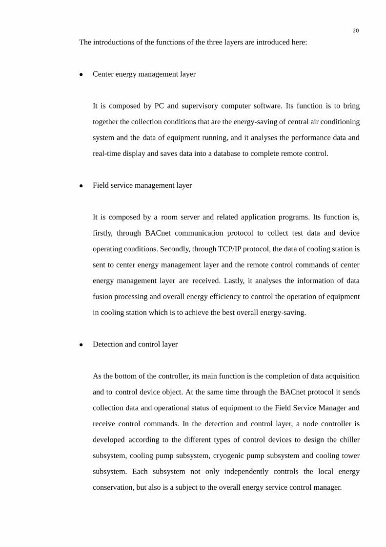
The introductions of the functions of the three layers are introduced here:
Center energy management layer
It is composed by PC and supervisory computer software. Its function is to bring
together the collection conditions that are the energy-saving of central air conditioning
system and the data of equipment running, and it analyses the performance data and
real-time display and saves data into a database to complete remote control.
Field service management layer
It is composed by a room server and related application programs. Its function is,
firstly, through BACnet communication protocol to collect test data and device
operating conditions. Secondly, through TCP/IP protocol, the data of cooling station is
sent to center energy management layer and the remote control commands of center
energy management layer are received. Lastly, it analyses the information of data
fusion processing and overall energy efficiency to control the operation of equipment
in cooling station which is to achieve the best overall energy-saving.
Detection and control layer
As the bottom of the controller, its main function is the completion of data acquisition
and to control device object. At the same time through the BACnet protocol it sends
collection data and operational status of equipment to the Field Service Manager and
receive control commands. In the detection and control layer, a node controller is
developed according to the different types of control devices to design the chiller
subsystem, cooling pump subsystem, cryogenic pump subsystem and cooling tower
subsystem. Each subsystem not only independently controls the local energy
conservation, but also is a subject to the overall energy service control manager.

21
This development node controller, as shown in Figure 3-2, is responsible for the equipment
which includes: two refrigerating machines, three chilled water pumps, three cooling water
pumps, three cooling tower fans, valves, etc.
3.2 The function of control system
1. Server function of equipment room
Equipment room server is equivalent to a small-scale LAN controller which is specialized
management refrigeration station node controller to coordinate action between the node
controllers. It can complete the overall system energy saving control algorithm and its
specific functions are as follows:
Manual/automatic detection
Frozen station equipment startup, shutdown process control
Figure 3-2. Frozen station room controller object graph
22
The overall optimal control algorithm
Indoor and outdoor temperature measurement
RS485 communication
Ethernet communication
Communication and fault alarm
2. Refrigerating machine controller function
Refrigerating machine is the most important component of central air conditioning system
and it is known as the heart of the central air conditioning system. Controller is responsible
refrigerating machine’s startup/shutdown and monitor of the chiller operating conditions to
meet other equipment running in refrigeration station. It includes:
Manual/automatic detection
Indoor temperature/outdoor temperature detection
Cold temperature protection
Refrigerating machine on/off control
Chiller fault detection and alarm
RS485 communication
Communication fault detection and alarm
3. Cryogenic pump controller functionality
The controller main task is to complete the frequency conversion control of the chilled
water pump to achieve energy conservation and to monitor frozen water related equipment.
At the same time for the central air-conditioning and room manager discrepancy, the
controller increases the valve state detection and remote alarm capabilities. Its functions
are as follows:
23
Manual control operation: using hand-operating mode, variable-frequency drive
control the pump start, stop and run
Automatic control operation: using automatic control, equipment room server control
all the equipment’s start, stop and run
Variable-frequency drive output control
Variable-frequency drive detection and alarm
Frozen valve control, fault detection and alarm
Chiller condition monitoring
Chilled water flow rate detection
Chilled water pump fault detection and alarm
RS485 communication
Communication fault detection and alarm
The controller’s highest priority is manual control, then the equipment room server and
remote PC control. When the communication is normal, the controller follows the energy
saving control mode which can make whole equipment room server optimization. When
the communication fails, the controller uses the best cryogenic pump energy-saving mode
to independent control.
4. Cooling pump controller functionality
The controller’s main task is to complete the frequency control of cooling pump and
monitoring of cooling water related equipment, which includes the cooling water entering
and leaving temperature, water valves’ closure, cooling pump frequency control, pump
start and stop detection and control and signal communication.
Its main functions are as follows:
Manual control operation: using hand-operating mode, variable-frequency drive
control the pump start, stop and run

24
Automatic control operation: using automatic control, equipment room server control
all the equipment’s start, stop and run
Variable-frequency drive output control
Variable-frequency drive detection and alarm
Frozen valve control, fault detection and alarm
Chiller condition monitoring
Chilled water flow rate detection
Chilled water pump fault detection and alarm
RS485 communication
Communication fault detection and alarm
5. Cooling tower controller functions
The main task of the cooling tower controller is the operation of cooling tower blower
control to meet the cooling water temperature of refrigerating machine requirement. When
the condition is meet the requirement, controller can achieve energy-saving of cooling
towers and fault detection function of cooling tower equipment.
The functions are as follows:
Blower switch control
Cooling water temperature detection
Cooling tower temperature detection
Valve control
Flow switch detection
Blower fault detection and alarm
Blower running time and the number of records
RS485 communication and fault detection and alarm
25
Cooling tower controller not only receives the server’s control commands to achieve the
control of the blower (to achieve and overall energy efficiency), but also has an own
control algorithms in order to interrupt the communication system can run as usual.
3.3 Software design
Software is the soul of the computer. A computer has a good software system which the
computer’s performance will be the best. In the central air-conditioning control system
design, there are many different tasks and each task is different for real-time requirement of
CPU. In order to let the task meet the entire real-time requirement and to facilitate future
software upgrades and maintenance, the system uses embedded operating system to
achieve the development of central air-conditioning control system. There are some
specific descriptions following. [13]
3.3.1 Embedded real-time operating system
Embedded system is the computer system which is for the purpose of embedded
application. It will combine computer hardware and software to form a dedicated
computing device to achieve the completion of specific functions and tasks. The embedded
system advantage has small software code, highly automated and fast response and it can
easily suit for the real-time requirement and multi-task system. [14]
RTOS (Real-Time Operating System) is an operating system which can support the work
of real-time control system. It is a program set which makes the hardware of computer
system available by the software or firmware achieved and is a software layer between the
programmer and the machine hardware. [14]
26
RTOS is a new design idea and an open software framework. It has the basic function of the
operating system and can control the operation on the real-time system. According the
priority of each task, it also can make a reasonable allocation of CPU and occupied time of
resource among them. As the RTOS can make application system to be divided into
multiple tasks which greatly simplify the design of application system, software designers
can not significantly change the other tasks in the system to increase or delete a task and
greatly reduce the development time and the software development mission. It meets the
complicated micro-controller application requirement. [14]
3.3.2 Control flow’s design based on RTOS
1. Service Controller controls the whole system power on and shutdown
Power on Process: Opening the cooling pump Opening cooling tower fan
Opening a chilled pump (20 minutes delay) Opening the refrigerating machine.
Flowchart is shown in Figure 3-3.
Shutdown process: closing refrigerating machine (20 minutes delay) closing chilled
pump closing cooling pump closing cooling tower fan. Flowchart is in Appendix 1.
2. Other equipment control flow
Control flow of chiller, the chilled pump interrupt processing flow and cooling tower
control flow are shown in Appendices 2 to 4.

27
Figure 3-3. SD Power on Process
Symbol Description:
SD = frozen-stop service manager CD1 = cooling pump controller
CD2 = cooling tower controller CD3 = freezing pump controller
CD4 = water chiller controller

28
3.4 Hardware design
Hardware design includes node controller’s design and equipment room server’s design
which can more effectively control the system.
3.4.1 Node controller
The node controller of system develops by using PIC24FJ64GA006 microcontroller of
Microchip Inc. Microcontroller features are described as follows: [15]
Low-power and high-performance 16-bit SCM
Internal 128K on-chip Flash
Software stack can facilitate the achievement of the development of embedded
operating system
RICC on-ship
On-chip is also with compatibility of 10-bit analog-digital conversion module (A/D)
Two USART communication circuits and five PWM output circuits.
With five 16-bit internal timer / counter
Node controller includes chilled pump controller, cooling pump controller, cooling tower
controller, and water chiller controller. Although these controllers’ object and completion
of the function are not the same, they are basically the same basic circuit and almost all
need the following functions: data sampling, filtering, PWM output, RICC real-time timer,
digital input / output, RS485 communication, EEPROM and so on.

29
Node controller features are presented in the following figure:
In the basic circuit of node controller, there are AD sampling circuits, PWM control
circuits, RS485 communication circuits, power circuit, DO drive circuit and DI detection
circuit. There are brief introductions of these below.
1. PWM control circuit
CPU output signal is the 100 KHz PWM signal. First it goes through the DC signal which
is smoothly commutated by low-pass filter. Then, after the first operational amplifier is
used to amplify the output signal range between 0 to 10V, and the last operational amplifier
is used to ensure the equipment of the output capacity. [16] (Figure in Appendix 5)
2. Minimum CPU circuit in node controller (Appendix 6)
3. Signal filtering circuit
Because it is susceptible to noise interference in the AD sampling circuit, the filter circuit
Figure 3-4. Node controller function structure chart

30
and low-pass filter circuit should be used for processing in the circuit. [17] (Figure in
Appendix 7)
4. The power processing circuit
When a device requires a protection circuit which has a big overall flow and can achieve
accurate protection, the protection circuit often requires good coordination between several
protection devices to achieve the ideal protective effect. When the Voltage Dependent
Resistor (VDR) is in parallel with Transient Voltage Suppressor (TVS) directly, even if the
flow of VDR meets the total surge protection requirement of equipment, TVS will be
damaged first and can not exert the advantage of VDR. So we have a 7 mH inductor in
series with VDR and TVS. [18]
5. BACnet communication circuit
BACnet MS/TP uses RS-485 (also called EIA-485) standard as a physical layer and uses a
balanced data transmission mode. The transmission medium of RS-485 uses cheaper
shielded twisted pair and there can be articulated multiple receivers on transmission
medium. It has a strong anti-jamming capability, a easy network connection and a long
transmission distance. The transceiver of RS-485 is using SN65LBC184 of TI Company as
communications chip and it is the pin-compatible with the SN75176. [19]
Figure 3-5. The schematic diagram of cooperate between VDR and inductor

31
As the controller in the field distribution is generally in the 50 m-100 m away, these appear
some static electricity and interference signals data communication line such as surge
voltage. For protecting the CPU and RS-485 chip, two TVS are used in the interface and
optical coupling device is added between CPU pins and RS-485 chip to isolation. [19]
(Figure in Appendix 8)
6. DO drive circuit
In order to protect the SCM IO pin, optical couplers are used for power isolation and
increasing the transistor as an intermediate driver. Then through a 24V relay as a dry
contact output, it can control device with any type of power. For preventing too large
electromagnetic interference on the relay coil and contacts, there is increasing fly-wheel
diode (FWD) in the both ends of the coil and paralleling a 1000pF/2KV capacitor in the
both ends of contact. (Figure in Appendix 9)
7. DI detection circuit
DI detection circuit can protect the input pins of SCM and transform the input voltage into
3.3V which is the requirement of CPU by optical coupling device. (Figure in Appendix 10)
3.4.2 The design of equipment room server
The controller of equipment room server requires the circuits which have Ethernet
communication, RS-485 communication, the temperature acquisition circuit, digital signal
detection circuit, digital signal output control circuit, storage circuit and real-time clock
circuit, as shown in Figure 3-6. RS-485 communication, digital signal detection circuit,
digital signal output control circuit, storage circuit and real-time clock circuit are similar in
node controller, so the description is not repeated again here.

32
1. Micro-controller
When equipment server is implementing data communication, data analysis, data storage,
control algorithms and other functions, the system has relatively large spending. So it
requires of CPU to have more abundant resource, enough storage space and computing
ability. The system uses Microchip Company’s PIC18F8722 micro-controller to achieve
the design of the equipment room server. The performances of PIC18F8722 are as follows
[20]: (Figure in Appendix 11)
Powerful processing capability. PIC18 series is 8-bit microcontroller and uses
Reduced Instruction Set Computing (RISC) architecture. It also includes an 8 x 8
multiplying unit. It requires only one single instruction cycle to implement
multiplication by hardware. The PIC18 device has higher calculation throughput and it
reduces the code size for multiplication algorithms. So it can be used in many
applications where as the previous can only be used in digital signal processors.
Fast computing speed. PIC18 device uses Harvard architecture which separate
instruction bus and data bus and two-stage pipeline instruction fetch and execution. So
it has a larger advantage compared with other 8-bit micro-controller on the code
compression and implementation speed.
Figure 3-6. Schematic diagram of the equipment room server hardware

33
Variety power mode. It provides seven working modes and can be more effective for
power management.
128K Flash, 4K RAM, 1024 Bytes EEPROM in chip
2. Ethernet communication circuit
In the system of Ethernet communication design, Ethernet controller is selected as the chip
that is RTL8019AS. The chip’s main characteristics are as follows [21]: (Figure in
Appendix 12)
Compatible with Ethernet and IEEE802.3 protocol. Transmission wire cables are
10Base2, 10Base5, 10BaseT.
Support for 8-bit and 16-bit data bus
Support for full-duplex Ethernet function to speed up the channel bandwidth
Built-in 16KB SRAM. It can be used for RX/TX buffer and to reduce the speed
requirements of the main processor.
3. Data filter circuit
Figure 3-7. Simulation signal filter circuit

34
The advantage of the second-order low-pass filter (shown in Figure 3-7) is that the two
operational amplifiers of this filter circuit are used as a voltage follower. So the sensitivity
requirement of operational amplifier opening loop gain is not high for the circuit.

35
4 Research on energy saving of central air conditioning system in
Nanchang HongKeLong Supermarket (HKLS)
In this chapter, there is a project design of central air conditioning system for HKLS is
discussed. The chapter will introduce the basic parameter, preliminary design and the
equipment selection.
4.1 Calculation condition
The calculation condition, which includes the basic meteorological parameters, the
design of requirement and the indoor condition, is extrinsic factor of environment which
may be affected by the central air conditioning work efficiency.
4.1.1 Calculation of meteorological parameters
Summer ventilation temperature (dry bulb): 32℃
Summer outdoor atmospheric pressure: 969kPa
Winter ventilation temperature (dry bulb): 6℃
Winter outdoor atmospheric pressure: 987.2kPa
Summer air-conditioning temperature (dry bulb): 35.5℃
Summer air-conditioning temperature (wet bulb): 27.0℃
4.1.2 The scope and requirement of the design
The scopes of the design are:
The design of ventilation and exhausting system for fire protection in underground car
park

36
The design of summer air-conditioning and exhausting system for supermarket on the
1st and 2
nd floor
The design of positive pressure air supply in smoke prevention staircase
The design of ventilation and exhaust system in underground equipment room
Design requirements and conditions are listed in Table 4-1 and Table 4-2
Heating Ventilation Air conditioning Exhausting system
1 Basement
2 1st floor
3 2nd floor
4 Smoke prevention staircase
AreaNO.Design Content
Winter Summer Winter Summer
1 Basement 24-26℃ 50% 70% 55 15/person
2 1st floor 24-26℃ 50% 70% 55 13/person
3 2nd floor 24-26℃ 50% 70% 55 13/person
Noise level(dB) Fresh air targets (m3/h)
Temperature HumidityNO. Area
4.2 Preliminary design
Engineering design is central for air conditioning. It only requires designing the smoke
control and ventilation in basement. It also requires designing summer air-conditioning,
smoke control and ventilation on 1st and 2
nd floor of the supermarket.
Table 4-1. Fire protection for the building
Table 4-2. Design indoor condition of air conditioning

37
4.2.1 Purification of air conditioning system design
The ground floor supermarket:
The central air conditioning system should be used in the central area.
For the shop next to the pedestrian street, , it can be used semi- centralized air
conditioning system (fan coil and DOAS) which can self-regulate according to the
indoor load condition because the requirements of the indoor air quality, temperature
and humidity are different
For the area that is close to the door and a contact with the outside, it can be directly
used independent air-conditioning unit which have fan coil, as shown in Figure 4-1 to
Figure. 4-4 due to the infiltration of outdoor fresh air and do not need add fresh wind,
Figure 4-1. Layout of fresh air system Figure 4-2. Layout of CACS in Area 2
in Area 1
Figure 4-3. Layout of CACS in Area 3

38
Figure 4-4. Layout of fresh air system in Area 4
The 2nd
floor:
A centralized air conditioning system should be used in the central area.
The surrounding shops use semi-centralized (fan coil and DOAS) air conditioning
systems.
Few areas which are near the door and have fresh air infiltration are using independent
air-conditioning system with a fan coil, as shown in Figure 4-5 to Figure 4-8.
Figure 4-5. Layout of fresh air system Figure 4-6. Layout of CACS in Area 2
in Area 1
39
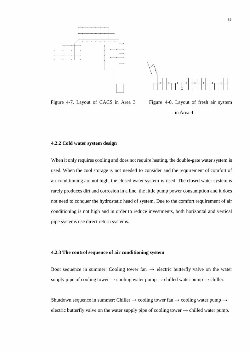
Figure 4-7. Layout of CACS in Area 3 Figure 4-8. Layout of fresh air system
in Area 4
4.2.2 Cold water system design
When it only requires cooling and does not require heating, the double-gate water system is
used. When the cool storage is not needed to consider and the requirement of comfort of
air conditioning are not high, the closed water system is used. The closed water system is
rarely produces dirt and corrosion in a line, the little pump power consumption and it does
not need to conquer the hydrostatic head of system. Due to the comfort requirement of air
conditioning is not high and in order to reduce investments, both horizontal and vertical
pipe systems use direct return systems.
4.2.3 The control sequence of air conditioning system
Boot sequence in summer: Cooling tower fan → electric butterfly valve on the water
supply pipe of cooling tower → cooling water pump → chilled water pump → chiller.
Shutdown sequence in summer: Chiller → cooling tower fan → cooling water pump →
electric butterfly valve on the water supply pipe of cooling tower → chilled water pump.
40
4.2.4 Noise elimination and shockproof method
The muffler should be added on the import and export pipeline of air conditioning and fan.
It is necessary to do the shock absorption which is required to add a rubber vibration pad on
the bottom of chiller, pump and other operating equipment. Also it is necessary to use
hanger frame when hoist fresh air unit, fan coil and muffler are shockproof.
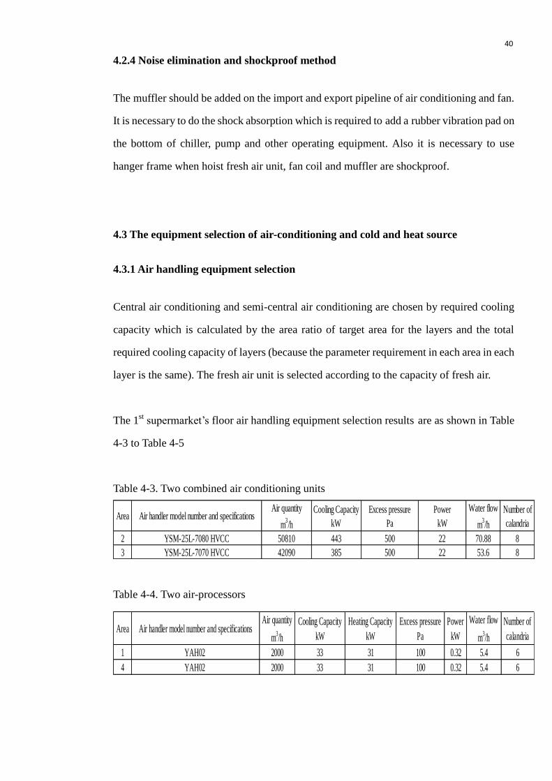
4.3 The equipment selection of air-conditioning and cold and heat source
4.3.1 Air handling equipment selection
Central air conditioning and semi-central air conditioning are chosen by required cooling
capacity which is calculated by the area ratio of target area for the layers and the total
required cooling capacity of layers (because the parameter requirement in each area in each
layer is the same). The fresh air unit is selected according to the capacity of fresh air.
The 1st supermarket’s floor air handling equipment selection results are as shown in Table
4-3 to Table 4-5
Table 4-3. Two combined air conditioning units
Area Air handler model number and specificationsAir quantity
m3/h
Cooling Capacity
kW
Excess pressure
Pa
Power
kW
Water flow
m3/h
Number of
calandria
2 YSM-25L-7080 HVCC 50810 443 500 22 70.88 8
3 YSM-25L-7070 HVCC 42090 385 500 22 53.6 8
Table 4-4. Two air-processors
Area Air handler model number and specificationsAir quantity
m3/h
Cooling Capacity
kW
Heating Capacity
kW
Excess pressure
Pa
Power
kW
Water flow
m3/h
Number of
calandria
1 YAH02 2000 33 31 100 0.32 5.4 6
4 YAH02 2000 33 31 100 0.32 5.4 6
41
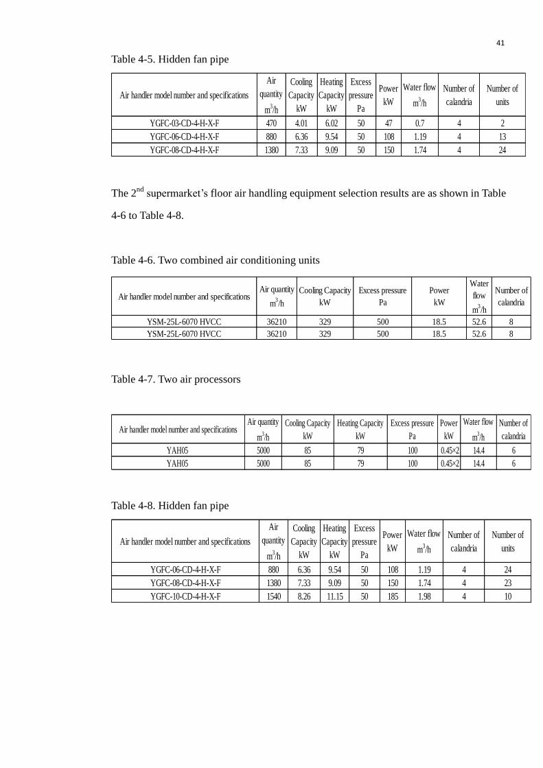
Table 4-5. Hidden fan pipe
Air handler model number and specifications
Air
quantity
m3/h
Cooling
Capacity
kW
Heating
Capacity
kW
Excess
pressure
Pa
Power
kW
Water flow
m3/h
Number of
calandria
Number of
units
YGFC-03-CD-4-H-X-F 470 4.01 6.02 50 47 0.7 4 2
YGFC-06-CD-4-H-X-F 880 6.36 9.54 50 108 1.19 4 13
YGFC-08-CD-4-H-X-F 1380 7.33 9.09 50 150 1.74 4 24
The 2nd
supermarket’s floor air handling equipment selection results are as shown in Table
4-6 to Table 4-8.
Table 4-6. Two combined air conditioning units
Air handler model number and specificationsAir quantity
m3/h
Cooling Capacity
kW
Excess pressure
Pa
Power
kW
Water
flow
m3/h
Number of
calandria
YSM-25L-6070 HVCC 36210 329 500 18.5 52.6 8
YSM-25L-6070 HVCC 36210 329 500 18.5 52.6 8
Table 4-7. Two air processors
Air handler model number and specificationsAir quantity
m3/h
Cooling Capacity
kW
Heating Capacity
kW
Excess pressure
Pa
Power
kW
Water flow
m3/h
Number of
calandria
YAH05 5000 85 79 100 0.45×2 14.4 6
YAH05 5000 85 79 100 0.45×2 14.4 6
Table 4-8. Hidden fan pipe
Air handler model number and specifications
Air
quantity
m3/h
Cooling
Capacity
kW
Heating
Capacity
kW
Excess
pressure
Pa
Power
kW
Water flow
m3/h
Number of
calandria
Number of
units
YGFC-06-CD-4-H-X-F 880 6.36 9.54 50 108 1.19 4 24
YGFC-08-CD-4-H-X-F 1380 7.33 9.09 50 150 1.74 4 23
YGFC-10-CD-4-H-X-F 1540 8.26 11.15 50 185 1.98 4 10

42
4.3.2 Cold and heat source selection
In summer the design of cooling load is 5700 kW, it is also needed to consider the safety
margin and then the total cooling load is 5700 x 1.1=6270 kW. So Nanchang HKLS
selected three centrifugal chillers. The cooling capacity of a single one is 2110 kW. The
parameters are shown in Table 4-9.
Table 4-9. Parameters of the chiller units
Chiller modelCooling Capacity
kW
Power
kW
Chilled water flow
m3/h
Cooling water flow
m3/h
YKEBEBH55CPE 2110 378 363 428
In the vapor compression refrigeration equipment, a centrifugal chiller has strong
refrigeration capacity and lower energy consumption. It should be precedence in the large
project which has big air conditioning load.
4.4 Automatic Control on Air-conditioning and Cooling/Heating source system
Automatic control can help fewer people to control the system. It will be used at fan
system, water system and smoke exhaust system. All of them can help the central air
conditioning system to reduce the labor force and the manual operation mistake
4.4.1 Automatic control of fan in air conditioning unit
The fan control system of air conditioning unit is shown in Figure 4-9. When the load of
air-conditioned room changes, the room temperature sensor sends a signal and transmits it
to the inverter. The inverter generates corresponding frequency and acts on fan which
changes its speed to change the amount of wind.
43
Figure 4-9. The control process of air condition unit fan
4.4.2 Automatic control of water system
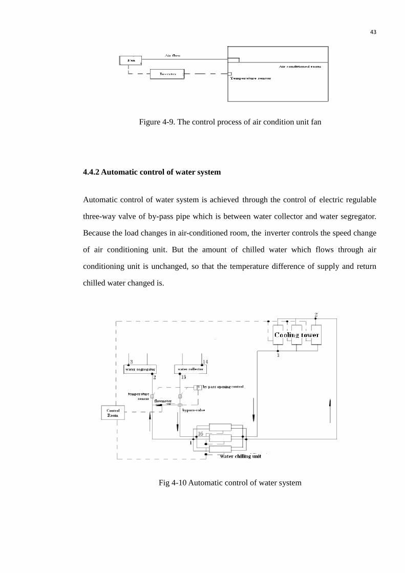
Automatic control of water system is achieved through the control of electric regulable
three-way valve of by-pass pipe which is between water collector and water segregator.
Because the load changes in air-conditioned room, the inverter controls the speed change
of air conditioning unit. But the amount of chilled water which flows through air
conditioning unit is unchanged, so that the temperature difference of supply and return
chilled water changed is.
Fig 4-10 Automatic control of water system

44
According to the temperature difference of supply and return water, the signal from
temperature sensor will be sent to the refrigerator control room. Thus the automatic control
of water system corresponding controls the opening of electric regulable three-way valve
to check the by-pass flow. If the by-pass flow is 90 % of one chiller’s flow, the signal will
be sent to the control room and the control room will automatically (or manually) close a
chiller, at the same time a cooling tower will be linkage closed. The above process will
achieve energy saving, just like in Figure 4-10.
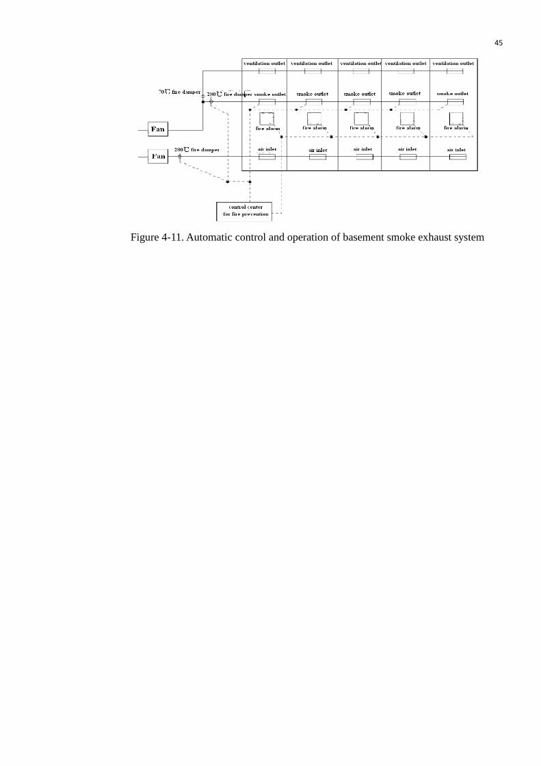
4.4.3 The automatic control and operation of basement smoke exhaust system
The basement ventilation system double acts also a smoker exhaust system. In other words,
it can put ventilation system and smoke exhaust system closely together and merge them
into a complex system. The complex system is usually used as a mechanical ventilation
system and it is used as a mechanical smoke exhaust system when there is a fire.
Ventilation system and smoke exhaust system use different air ducts. One air duct is
designed according to the requirement of the ventilation system, and the other one is
designed according to the requirement of the smoke exhaust system. The operations of
these two systems are controlled by the opening and closing of valve. Normally the fire
damper on smoke exhaust pipe is closed and the fire damper on ventilation pipe is opened.
The fan is running to exhaust emission of vehicle and to ensure meeting the health
requirements.
When breaking out of fire, the 70℃ fire damper on ventilation pipe will be closed.
According to the fire alarm or through the control center for fire prevention, the fire
damper can be automatically (or manually) opened on the smoker exhaust pipe in the area
where there’s a fire and to do the smoke exhausting. The automatic control is shown in
Figure 4-11.
45
Figure 4-11. Automatic control and operation of basement smoke exhaust system
46
5 Improvement Project Program for Energy Saving in Central Air
Conditioning System in Nanchang HKLS
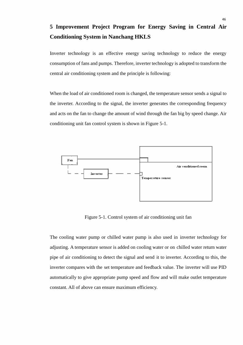
Inverter technology is an effective energy saving technology to reduce the energy
consumption of fans and pumps. Therefore, inverter technology is adopted to transform the
central air conditioning system and the principle is following:
When the load of air conditioned room is changed, the temperature sensor sends a signal to
the inverter. According to the signal, the inverter generates the corresponding frequency
and acts on the fan to change the amount of wind through the fan big by speed change. Air
conditioning unit fan control system is shown in Figure 5-1.
Figure 5-1. Control system of air conditioning unit fan
The cooling water pump or chilled water pump is also used in inverter technology for
adjusting. A temperature sensor is added on cooling water or on chilled water return water
pipe of air conditioning to detect the signal and send it to inverter. According to this, the
inverter compares with the set temperature and feedback value. The inverter will use PID
automatically to give appropriate pump speed and flow and will make outlet temperature
constant. All of above can ensure maximum efficiency.

47
The specific working principle is:
When the air conditioning usage amount or temperature is decreased, it will be detected
that the temperature of cooling water or chilled water outlet will be decreased or increased.
Through the inverter’s PID algorithms the pump speed is reduced, then the water flow is
reduced too. It should be ensured that the minimum threshold frequency of pump is more
than 25 Hz. Then the temperature is ensured to be constant and it is reducing the energy
consumption and vice versa.
Diagram is as follows:
Figure 5-2. Principle of central air conditioning operation
5.1 Equipment overview
The fan and pump, their number and installation location in the central air conditioning
system of Nanchang HKLS are shown in Table 5-1

48
Table 5-1 Air processor and pump
ID Equipment Model number Motor Power Number Installation location
1 Air processor YSM-25L-7070-HVCC-L 22kW 1 1F
2 Air processor YSM-25L-6070-HVCC-R 18.5kW 1 1F
3 Air processor YSM-25L-6070-HVCC-L 18.5kW 1 2F
4 Air processor YSM-25L-7080-HVCC-R 30kW 1 2F
5 Chiller water pump 55kW 3 -1F
6 Cooling water pump 75kW 3 -1F
7 Cooling tower fan 7.5kW 3 3F
5.2 Improvement plan
Even though there have already be chosen the equipment and the process has been
designed, there should be a plan of improvement and systemic segmentation which is
suitable of the each floor environment to get the maximum energy saving and efficiency.
5.2.1 The equipment of improvement plan for energy saving
For the fans and pumps, Nanchang HKLS takes into account the actual operation situation
and energy saving to improve energy saving of following equipments:
The two air processors in 1st floor: Motor powers are 22 kW and 18.5 kW
The two air processors in 2nd
floor: Motor powers are 18.5 kW and 30 kW
The three chiller water pumps in basement: Motor powers are 55 kW (Using two of
them and one for preparation)
Thethree cooling water pumps in basement: Motor powers are 75 kW (Using two of
them and one for preparation)
The one cooling tower fan in 3rd
floor: Motor power is 7.5 kW
The total power of improvement: 356.5 kW

49
5.2.2 Specific measure
An inverter and temperature controller is added to each fan and pump. The fan speed is
controlled by an inverter. The air flow and pump flow are adjusted to achieve energy
saving, as shown in Figure 5-3.
Figure 5-3. Project of collocation
The specific process is:
To install 2 sets of 75 kW Siemens inverters and one set of inverter control cabinet on
the -1F. To install temperature sensor on cooling water return pipe.
To install 2 sets of 55 kW Siemens inverters and one set of inverter control cabinet on
the -1F. To install pressure sensor on chilled water outlet pipe.
To install 1 set of 22kW and 1set of 18.5 kW Delta inverters and one set of inverter
control cabinet on the 1st floor. After installing the inverter, it can achieve energy
saving and reduce environmental noise can be achieved.

50
To install 1 set of 18.5 kW and 1set of 30 kW Delta inverters and one set of inverter
control cabinet on the 2nd
floor. After installing the inverter, it can achieve energy
saving and reduce environmental noise can be achieved.
To install 1 set of 7.5 kW Delta inverter for energy saving of cooling tower fan and to
install 1 set of inverter control cabinet on the 3rd
floor. According to the level of the
cooling water temperature, it divides into four levels of automatic control for wind
speed.
To install 1 set of Siemens PLC and an analog input/output module which has built-in
EVIEW touch screen for parameter settings. It also has manual/automatic conversion
and monitors the fan/pump operation status, system temperature, pressure, speed
display and fault records.
To install the signal cable and power cable.
To use the control mode: It divides two modes which are power frequency and
frequency conversion. In the normal circumstance it is operated by frequency
conversion to achieve equipment soft start/ soft stop. When the inverter conks out, it
will switch to the power frequency. It should be noted that the contactor of inverter’s
output side should be disconnected to ensure continuous operation of the air
conditioning.
5.3 Technical feature
For this project, Siemens and Delta intelligent inverters which are specifically for HVAC
are used. The series has the following advantages:
Optimized input/ output functions: It meets all the required control and monitoring

51
functions for a typical HVAC application.
Automatic optimization of the debugging process: Only 12 basic parameters set can
meet all HAVC applications. Expansion parameter can be flexible to meet the
application requirements. Debugging is simple and maintenance workload is small.
Complete electric protection: It can protect overvoltage, undervoltage, overcurrent,
motor overheat, ground fault, inverter internal fault and so on.
Soft start/ soft stop function: It avoids the “water hammer phenomenon” and extends
the motor and pump usage time.
Cable operation: The cable between the motor and the inverter can increase to 150 m
without output reactor.
Energy consumption optimization (ECO): When the set value is reached, the control
system will automatically optimize the electrical energy consumption. Therefore, in
addition to providing energy saving from speed control, the motor is also running at
maximum efficiency.
5.4 Technical and economic analysis
Due to pump load, torque load is variable and the power consumption of pump motor is the
cube of its flow. So if the motor speed is decreased a little, the motor power consumption
will be significantly reduced. Frequency conversion technology for energy saving is based
on this principle which is achieved through changing the frequency of the motor to achieve
the motor frequency change and then changing the pump flow and pressure to save energy.
In the conventional central air conditioning system, due to the circulating pump is

52
constantly running at rated speed, the load is low and water quantity can not be a
corresponding change, the energy will be wasted. If using frequency conversion
technology to transform, then it can make quantity of revolving water is changed by
automatic adjust pump speed which according to heat load changing. Under the premises
which ensure the normal operation of the system, what can reduce energy loss and the
effect is obvious. The relationship of pump speed, water quantity and power is shown in
Table 5-2.
The energy saving formula of pump speed and flow is:
P=K x n3 (1)
where
P = the power [W]
K = the pump speed [rpm]
n = the water quantity [m3/h]
Table 5-2. Relationship of pump speed, water quantity and power by Formula (1)
Frequency Pump speed reduction Water quantity reduction Power decrease
45Hz 10% 10% 27.10%
40Hz 20% 20% 48.80%
35Hz 30% 30% 65.70%
30Hz 40% 40% 78.40%
In addition, due to it is need to consider other factors, the central air conditioning
engineering design should give a 10-15% margin base on the theoretical design value,
and hence to the system consumes more power. If using the frequency technology to
transform, the margin can be saved completely.
Under normal circumstances, the energy-saving rate of each motor can be 20-30% or
more after using frequency energy saving technology. Conservative estimate is that if the
energy-saving rate of motor is 20% and it is running 12 hours per day, then the following

53
savings can be achieved:
The monthly power consumption of transformation equipment: (30 days per month)
12 hours x 30 days x 356.5 kW=128340 kWh
The monthly saving electricity:
128340 kWh x 20% = 25668 kWh
The annual saving electricity: (8 months per year for using)
25668 kWh x 8 = 205344 kWh
If the price of one kWh is 0.7¥, then the saving money per year is :
205344 kWh x 0.7¥/kWh = 143740.8¥ (about 14374 €)
One set of frequency energy saving system costs about 230 thousands Yuans. Then it
takes about 16 to 20 months to recover from investment costs. It also extends the usage
time of pump and reduces the maintenance and repair costs to get more indirect economic
benefits.

54
6 Conclusions
In this thesis, the problem and the cause of the problem have been discussed according to
the research of the specific practical problem of the traditional energy saving system.
Based on the theory of intelligent building management system (IBMS) and the
energy-saving central air-conditioning inverter, it can adopt a means of vector control to
achieve the integrated use of the technology of dynamic process and the corresponding
compensation, constant torque regulator, instantaneous flow of negative interference
suppression, and then it can find the solution to improve the central air conditioner
equipment and improve HVAC energy saving control system.
Firstly, in the thesis the basic work principle of energy saving of the HVAC was introduced
and the way to improve the energy saving process was researched, which is through
temperature controller control to the temperature around the inverter. The inverter changes
the conversion to regulate the water pump electromotor and the turning speed of the
air-blower to control the change of the volume of the wind and flow.
Secondly, due to the disadvantage of the traditional energy saving control system, the
energy saving control system is improved through improving the controller design,
software design, hardware design and electromagnetic interference design. This way the
energy saving system can achieve the optimum control effect and improve the stability of
whole system.
Thirdly, the thesis included a case study in energy saving program in Nanchang
HongKeLong Supermarket and gave ideas for an improvement project. It was found that
the implementation of the energy saving for central air conditioning system can avoid
unreasonably inefficient energy use, reduce air conditioning energy consumption and
improve energy efficiency.
Finally, through all those methods, the central air conditioning system and its control
system can achieve more energy saving and as well as economic and social benefits.

55
References
1 Gordon Feller 2008 (on line)
China’s Energy Demand
http://www.ecoworld.com/energy-fuels/chinas-energy-demand.html
Retrieved 10 May 2010
2 Shenzhen information website 2003
Energy saving technology introduction of central air conditioning
(online)
http://www.cedm.com.cn/site150/info12484.htm
Retrieved 10 May 2010
3 Zhu Weifeng and Jiang Yi 2000
Normal question analysis of air conditioning system. HVAC. 4-11
4 Zeng Yong 2004 (on line)
The use of transducer in the water system of air-conditioning
http://wenku.baidu.com/view/8bc968563c1ec5da50e270c6.html
Retrieved 15 May 2010
5 Liu Daoshou and Zhang Lihua 2003
The Applications of Transducer and PLC in Central Air-Conditioning
System. School newspaper of Nanjing Institute of Industry Technology 4
(1), 18.
6 Li Jianhua and Kang Xiangjiu 2003 (on line)
The Feasibility of inverter energy saving in cycle pump of Central Air
Conditioning
http://www.docin.com/p-70561783.html

56
Retrieved 22 May 2010
7 Hou Wenxia and Lu Sutian 2000
The Application of FD Speed Control Technology in Central Air
Conditioning. Journal of Electric Equipment for Machine Tool 2000 (2),
34.
8 Zhang Qinglin, Duan Li and Sun Qianchen 2008 (on line)
The Application of FD Speed Control Technology in Central Air
Conditioning. Journal of Application 23 (2), 24.
9 Zhang Baoshou and Zuo Tai 2000
Why the Inverter is Needed in Central Air Conditioning. Journal of
Energy Technology 2000 (2), 109.
10 Zhuang Yiqiang 2002 (on line)
The Feasibility of inverter energy saving in cycle pump of Central Air
Conditioning
http://www.docin.com/p-50167173.html
Retrieved 4 June 2010
11 Pan Jinwen and Wang Qiongzhen 2007
The Application of Inverter Control Technology in Water System of
Central Air Conditioning. Journal of Construction and Design for
Project 2007 (1), 23-25.
12 Zhao Bing 2000
The Application and development of Inverter Energy Saving in Central
Air Conditioning. Journal of Fujian Energy Development and
Conservation 2000 (1), 27.

57
13 Abraham Silberschatz, Peter Baer Galvin and Greg Gagne 2005
Operating System Concepts. Seventh edition. John Wiley & Sons, Inc.
USA.
14 Gary J. Nutt 1997
Operating System: A modern perspective. Longman Publishing Group.
USA.
15 PIC24FJ64GA006 Data book 2010
Microchip Technology Inc.
16 David F. Stout and Milton Kaufman 1983
Handbook of Operational Amplifier Circuit Design. Mc Graw-Hill Inc.
USA
17 Mo Fujiang, Ruan Jiangjun and Chen Yunping 2003
Study on Integrated Surge Suppressor. Journal of East China Electric
Power 2003 (2), 1-3.
18 Liu Weiheng 2004
Practical Electronic Circuit Foundation. Electronics Industry
Publishing Corporation. Beijing.
19 Dong Chunqiao 2003
The Principle and Application of Intelligent Building Management
BACnet. Electronics Industry Publishing Corporation. Beijing.
20 PIC18F8722 Data book 2010
Microchip Technology Inc

58
21 RTL8019AS Data book 2010
Realtek Semiconductor Co., Ltd.

59
Abbreviations
HVAC: Heating, Ventilation and Air-Conditioning
VAV: Variable Air Volume
RTOS: Real-Time Operation System
SCM: Single Chip Micyoco
RICC: Resistance, Inductance and Capacitance Circuit
USART: Universal Synchronous Asynchronous Receiver Transmitter
PWM: Pulse-Width Modulation
EEPROM: Electrically Erasable Programmable Read Only Memory
FWD: Fly-Wheel Diode
RISC: Reduced Instruction Set Computing
DOAS: Dedicated Outdoor Air System
ECO: Energy consumption optimization
IBMS: Intelligent Building Management System

60
Appendices
Appendix 1 SD shutdown process
Appendix 2 Control flow of chiller
Appendix 3 Chilled pump interrupt processing flow
Appendix 4 Cooling tower control flow
Appendix 5 PWM output circuit
Appendix 6 Minimum CPU circuit in node controller
Appendix 7 Low-pass filter circuit
Appendix 8 RS-485 communication circuit
Appendix 9 DO relay drive circuit
Appendix 10 DI detection circuit
Appendix 11 Minimum CPU circuit of equipment room controller
Appendix 12 Ethernet communication module circuit diagram

Appendix 1
Symbol Description:
SD = frozen-stop service manager; CD1 = cooling pump controller;
CD2 = cooling tower controller; CD3 = freezing pump controller;
CD4 = water chiller controller

Appendix 2

Appendix 3

Appendix 4

Appendix 5
Appendix 6
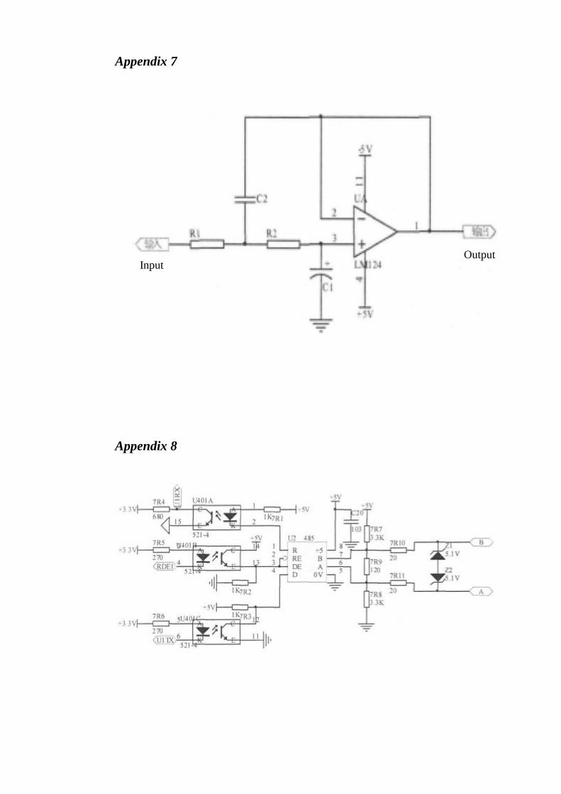
Appendix 7
Appendix 8
Input Output

Appendix 9
Appendix 10

Appendix 11
Appendix 12