Embed Size (px)
Citation preview

Attic insulation
*Manitoba Hydro is a licensee of the Trademark and Official Mark.
3 POWER SMART GUIDE: Energy saving solutions for home comfort

Publications in this series
1 Sealing, caulking & weatherstripping 6 Heating systems
2 Basement & crawlspace insulation 7 Water heaters
3 Attic insulation 8 Indoor air quality & ventilation
4 Wall insulation 9 Energy saving tips
5 Doors & windows
For more information on Power Smart*:
Telephone: 204-480-5900 in Winnipeg Toll-Free: 1 888 MBHYDRO (1-888-624-9376) Or visit hydro.mb.ca
*Manitoba Hydro is a licensee of the Trademark and Official Mark.

Attic insulation
BOOKLET #3

BOOKLET #3
Important Notice Care has been taken to ensure the accuracy of this booklet. However, because of changing codes, standards and equipment design, you should seek professional advice before insulating the attic in your home. Manitoba Hydro cannot assume responsibility for injury, loss or damage that results from relying solely on the information contained in this booklet.

1ATTIC INSULATION
IntroductionWhy retrofit? 2Do it yourself or hire a contractor 2
Checking your atticPrecautions before starting 4How to inspect your attic 5• Gaining access 5• Checking for roof leaks 6• Existing insulation 6• Air leaks 7• Vapour barriers 9• Ventilation 10
Preparing the atticTools required 11Step one: reduce air leakage 11Step two: ensure adequate ventilation 17
Insulating the atticAccessible attics 20• Installing batt type insulation 20• Installing loose fill insulation 22• Additional points when insulating 23Storey-and-a-half attics 24• Outer attic floor and attic ceiling 24• Knee walls 25• End walls 26• Sloped ceilings 26Cathedral and flat ceilings 27• Insulate below the existing ceiling 27• Insulate above the existing roof 28• Build a new peaked or sloped roof 29
TablesTable 1 — Insulation summary 30
Contents

2 BOOKLET #3
Why retrofit?Save money — Heating a home, especially in our climate, can be expensive. Most of the homes in Manitoba were constructed during an era of plentiful and inexpensive energy supplies. As a result, these homes were built with only a small amount of attic insulation. With today’s much higher energy costs, retrofitting your home’s attic is often one of the least costly and most effective ways to reduce your energy bills.Increase comfort — A well-insulated house is a comfortable house. A properly insulated attic pays dividends year-round; your home will not only be warmer in the winter, but it will also be cooler and more comfortable in the summer.Conserve energy — Approximately 13 per cent of Manitoba’s annual energy use goes to heat our homes. Much of that energy can and should be saved. Retrofitting your home will help save our valuable energy resources at a cost lower than producing new energy supplies.Help the environment — Making your home more energy efficient means lower greenhouse gas emissions, which is good for the environment.
In addition to these major benefits, retrofitting often can also improve the appearance, longevity, and safety of your home.
Do it yourself or hire a contractorThis booklet has been designed to meet the needs of both the experienced
and the inexperienced “do-it-yourself-er”. Most of the work described can be done by a homeowner with common household tools. By doing it yourself, both the savings and job satisfaction can be high. Please read this booklet carefully. For additional information, please contact us (see inside front cover) or your local building material supplier.
If you intend to have a contractor do some or all of the work, this booklet will still be of interest to you. You are more likely to get the results you want if you are knowledgeable about the work and take an active interest in what the contractor does. For further information on how to hire a contractor, call the Consumer Protection Office at (204) 945-3800 (Winnipeg), 1-800-782-0067 or email [email protected].
Introduction
3ATTIC INSULATION
The types of attics and ceilings discussed in this booklet are illustrated in Figure 1. Whether you do it yourself or hire a contractor, please remember that this booklet does not describe every possible technique for insulating an attic.
Each home is unique and you or your contractor may find it necessary or desirable to deviate from the techniques shown in this booklet.
Figure 1
Accessible attic
Cathedral ceiling
Flat ceiling
Storey-and-a-half attics

4 BOOKLET #3
Precautions before startingBefore you tackle the job of checking and retrofitting your attic, make sure
you are familiar with the following safe working procedures:
• Provide good lighting (preferably a fluorescent trouble light, since an exposed incandescent bulb can ignite some types of insulation).
• Lay boards down over the tops of the joists or trusses to form a walkway as shown in Figure 2 (the ceiling below won’t support your weight).
• Wear a dust mask.• Wear gloves and thick, loose clothing with long sleeves and tight cuffs to
minimize skin irritations when handling insulation.• Wear goggles if there is a possibility of insulation dust coming in contact
with your eyes.• A hard hat can be worn to keep insulation particles out of your hair and to
prevent head injuries.• Locate all electrical wiring in your attic, and then avoid all unnecessary
contact with it. If it doesn’t look safe (cracked covering, bare wires, open
Checking your attic
Figure 2
Provide good lighting
Wear appropriate safety gear (goggles, mask,
hard hat, safety boots)
Wear gloves and thick loose clothing to minimize
skin irritations
Lay boards on joists to form walkway
Joists
junction boxes) have it inspected by a qualified electrician.

5ATTIC INSULATION
• Most rigid insulation is very flammable and should be kept well away from sources of heat. If used indoors, cover any exposed rigid insulation with 13 mm (1/2 inch) gypsum wallboard or equivalent.
• If there are nails protruding from the attic floor, wear safety boots. Otherwise wear shoes with good traction (running shoes).
• Use ladders correctly; support them properly and have a helper steady them.• If you work on the roof, use a safety rope tied to a secure place.• The attic in your home can be very hot during the summer. Work on cool
spring or fall days, or on cool summer evenings.• When cleaning up insulation fibres or dust, use a vacuum cleaner. If you can
only sweep up the material, dampen it first to prevent particles from becoming airborne.
• After the work is complete, vacuum your work clothes and then wash them separately from other clothing.
How to inspect your atticThe first step is to determine what condition your attic is in now. A good
understanding of what shape your attic is in will be essential in planning what has to be done, and in choosing the best materials or selecting the proper contractor.
You’ll need to determine the type, amount and condition of existing insulation. You should also assess whether the attic is properly vented or if it has a moisture problem.
The next few pages describe how to inspect your attic to determine your retrofitting needs.
Gaining access
Most homes have interior access doors or hatches that lead to the attic. A good job of inspecting and insulating the attic depends on being able to gain access to all parts of the attic. If your home lacks access to any portion of the attic, consider one of the following options:• Cut into the attic from outside the house. This can be done by cutting a hole
in one of the gable ends. A large attic vent mounted in a small door can fill the opening. Be sure to add flashing and caulking to ensure that rain water can’t penetrate into the attic.
6 BOOKLET #3
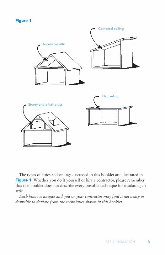
• Consider cutting into the attic from inside the house. The hole can be made into a decorative hatchway or it can be located in an out-of-the-way place such as a closet or hallway. Be careful not to make entry too difficult. If the hatchway is too close to the perimeter of the attic, there may be insufficient headroom above the hatch. Plan the job carefully. First, cut a small hole and check to make sure that no wires or structural supports will be damaged. Then cut the hatchway so that it spans between adjacent joists and is as wide as possible in the other direction — up to one metre.In some cases, there may not be sufficient space in which to work. Evaluate
the condition of the attic as best you can in these circumstances. If additional insulation is required, it can be blown in.
Finally, some houses may not have an open attic above part or all of the house (e.g. cathedral ceilings, flat roofs, sloped ceilings in 11/2- and 21/2-storey homes). To assess the type, amount, and condition of insulation, you can drill small inspection holes in an out-of-the-way place such as a closet or hallway.
Checking for roof leaks
After gaining access to the attic, check for roof leaks. The effectiveness of most insulations is severely reduced by moisture. Any leaks in the roof must be repaired before adding insulation.
Common causes of roof leaks include faulty roof flashing, worn out shingles, and improperly installed attic vents. Look for clues such as wetness or water stains on the underside of the roof, wet insulation, or stains on the ceiling below. The best time to check for these signs of roof leaks is during or just after a rain storm.
Be careful not to confuse signs of condensation with the effects of moisture from a leaky roof. An explanation of what causes condensation is provided in the section on “Air leaks”.
Roof leaks can also be the result of ice dams forming along the eaves or valleys of a roof during winter or early spring. These ice dams cause water to back up under the shingles and leak into the attic. Removing snow from the roof will eliminate ice damming, but is not always practical. Ice damming can usually be reduced by first sealing and insulating the attic, and by clearing and improving the ventilation. In severe cases, it may be necessary to add moisture protection under the shingles along the eaves and valleys. If your home suffers from ice damming, get advice from a roofing contractor with expertise in dealing with this problem.
Existing insulation
Insulation should be in good condition — evenly distributed and dry.

7ATTIC INSULATION
Whatever type it is, if it is not wet, leave it in place, since new insulation can be added on top. If it is wet, remove it altogether.
Measure the average depth of the existing insulation with a ruler in several locations. Calculate the total insulation value using the RSI value (R-value) shown in Table 1. If you have trouble identifying the insulation type, take a small sample to a local building supply outlet for help.
Attics which are open and easily accessible should be insulated to a minimum of RSI-8.8 (R-50). If the existing insulation is close to this value (say RSI-5.3 (R-30) or better) additional insulation may not be cost-effective as it will result in only a small reduction in heat loss.
If your home has a flat ceiling, sloped ceiling (as in 11/2- and 21/2 storey homes) or cathedral ceiling, it should be insulated to a minimum of RSI-5.0 (R-28). Unfortunately, it is difficult and expensive to add insulation to these types of ceilings. However, if combined with general renovations or roof replacement, additional insulation can become economically attractive.
If your attic is inadequately insulated, add insulation as described later in this booklet.
Some attics in older homes may contain vermiculite insulation. Vermiculite in the loose form is light brown/grey/gold in colour and is a pebble-like material ranging from 2 to 10 mm in diameter. Vermiculite, commonly sold under the trade name Zonolite, may contain asbestos.
The best way to reduce the risk of asbestos exposure is to avoid disturbing the vermiculite insulation in any way. You should not attempt to remove this type of insulation yourself, and should instead hire a contractor certified in asbestos abatement procedures. For more details on vermiculite insulation, check out the Safe Manitoba bulletin available through Manitoba Workplace Safety and Health or online atsafemanitoba.com/bulletins.aspx
Air leaks
Check diligently for any air leaks into the attic from the house so that they can be sealed prior to insulating, as described later in this booklet.
If there is evidence of moisture damage in the attic, such as wet insulation, yet the roof appears free from leaks, suspect condensation from excessive air leakage. During the winter, warm air which escapes from the house can carry significant amounts of water vapour into the cold attic where it may form condensation or frost. On a warm day, the frost will melt and the water will drip into the insulation. If excessive, this moisture can seriously damage the insulation and attic framing.
8 BOOKLET #3
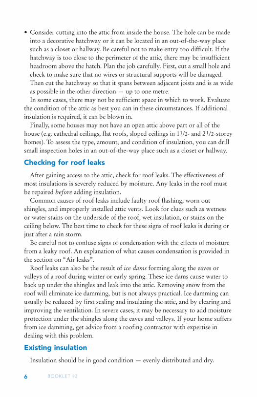
When searching for air leaks it might help to turn off your flashlight or trouble light and look for light from below. Some common locations of air leaks (see Figure 3) worth investigating include:
Figure 3 • Typical air leakage paths into an attic
Along the top of interior and exterior walls
Around plumbing stack Around the chimney
At ceiling light fixtures or electrical wires
Around ductingAround attic hatch

9ATTIC INSULATION
• Around the plumbing stack and other pipes entering the attic.• Around electrical wires or ceiling light fixtures that penetrate the attic
floor (be careful!).• Around ducting that enters the attic from inside the house — from
kitchen exhaust fans, bathroom vents, etc. (Joints in the ductwork itself should be sealed with foil tape. The ductwork should be wrapped with at least 100 mm (4 inches) of insulation to prevent condensation. It is especially important that no exhaust fans discharge into the attic. They should discharge to the outside, but not directly below the eave vents.)
• At the junction of the ceiling and interior wall partitions. Pull back the insulation where necessary to check for cracks formed along interior walls.
• At the top of interior and exterior walls. Check to see if all the wall cavities are blocked from the attic (usually by a top plate).
• Around attic hatches. Hatches should be weatherstripped as you would a door to the outside. The hatch should also be sealed around the frame and between the casing and the ceiling.
• Around the chimney. Chimneys should not be sealed with any material that is (or may become) flammable. Page 16 describes how the gap around a chimney should be sealed.
Also remember that any openings made for inspection purposes are also potential sources of air leaks. They should be patched and sealed as soon as they are no longer required.
Moisture transport by air leakage is more significant than vapour diffusion (as described below), so the focus should be on air sealing.
Vapour barriers
While checking for air leaks, note whether there is a vapour barrier on the attic floor. The vapour barrier will probably be either a layer of kraft or waxed paper or, in more recently constructed homes, polyethylene.
The vapour barrier protects the attic insulation and framing by reducing the movement of water vapour by diffusion from the house to the attic. Diffusion is the movement of water vapour through a permeable material. Because kraft or waxed paper and polyethylene are relatively impermeable to water vapour, they are classified as vapour barriers.
If your home does not have a kraft/waxed paper or polyethylene vapour barrier, it still is possible to provide adequate moisture protection. In these cases, seal all air leaks through the ceiling, as described later in this booklet, and then paint the underside of the ceiling with two coats of a low-permeability paint (oil, enamel or latex vapour barrier paint).
10 BOOKLET #3
It is also important to maintain a reasonable level of humidity in the home during winter to protect the attic from excessive moisture.
If there is an existing vapour barrier, patch any obvious breaks and seal air leaks as described later in this booklet before adding insulation.
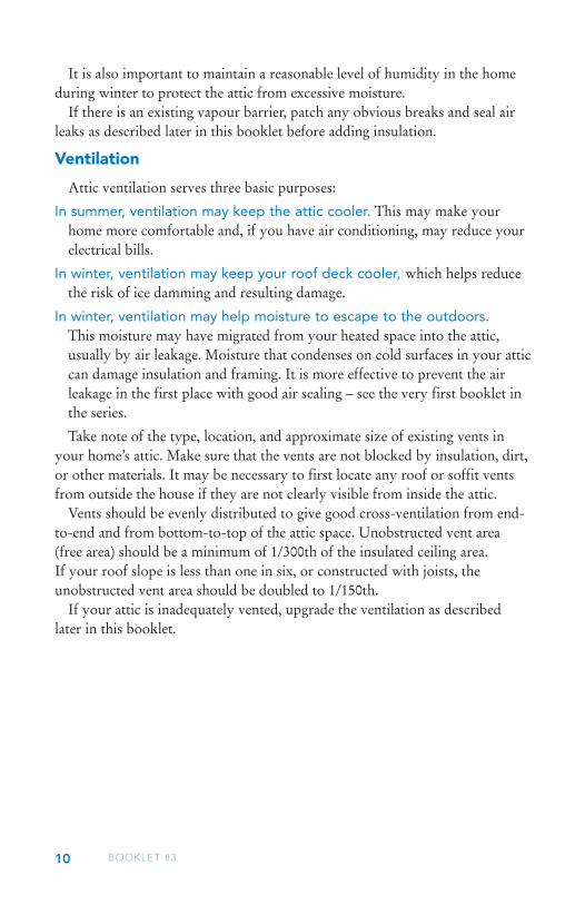
Ventilation
Attic ventilation serves three basic purposes:
In summer, ventilation may keep the attic cooler. This may make your home more comfortable and, if you have air conditioning, may reduce your electrical bills.
In winter, ventilation may keep your roof deck cooler, which helps reduce the risk of ice damming and resulting damage.
In winter, ventilation may help moisture to escape to the outdoors. This moisture may have migrated from your heated space into the attic, usually by air leakage. Moisture that condenses on cold surfaces in your attic can damage insulation and framing. It is more effective to prevent the air leakage in the first place with good air sealing – see the very first booklet in the series.
Take note of the type, location, and approximate size of existing vents in your home’s attic. Make sure that the vents are not blocked by insulation, dirt, or other materials. It may be necessary to first locate any roof or soffit vents from outside the house if they are not clearly visible from inside the attic.
Vents should be evenly distributed to give good cross-ventilation from end-to-end and from bottom-to-top of the attic space. Unobstructed vent area (free area) should be a minimum of 1/300th of the insulated ceiling area. If your roof slope is less than one in six, or constructed with joists, the unobstructed vent area should be doubled to 1/150th.
If your attic is inadequately vented, upgrade the ventilation as described later in this booklet.
11ATTIC INSULATION
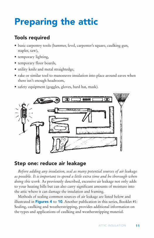
Tools required• basic carpentry tools (hammer, level, carpenter’s square, caulking gun,
stapler, saw),
• temporary lighting,
• temporary floor boards,
• utility knife and metal straightedge,
• rake or similar tool to manoeuvre insulation into place around eaves when there isn’t enough headroom,
• safety equipment (goggles, gloves, hard hat, mask).
Preparing the attic
Step one: reduce air leakageBefore adding any insulation, seal as many potential sources of air leakage
as possible. It is important to spend a little extra time and be thorough when doing this work. As previously described, excessive air leakage not only adds to your heating bills but can also carry significant amounts of moisture into the attic where it can damage the insulation and framing.
Methods of sealing common sources of air leakage are listed below and illustrated in Figures 4 to 10. Another publication in this series, Booklet #1: Sealing, caulking and weatherstripping, provides additional information on the types and applications of caulking and weatherstripping material.

12 BOOKLET #3
• Plumbing stack — This is difficult to seal because it is subject to expansion and contraction as warm water flows through it. Use a flexible seal consisting of acoustical sealant, heavy polyethylene, a hose clamp or zip ties on the pipe, and staples or short screws at the ceiling, as shown in Figure 4.
• Electrical wires and ceiling light fixtures — Caulk electrical wires where they penetrate the attic space as shown in Figure 5. Electrical boxes for ceiling light fixtures can be sealed with pieces of 0.15 mm (6-mil) polyethylene, acoustical sealant, and staples as shown in Figure 5. Alternatively, ceiling light fixtures can be sealed with caulking or CSA-approved foam gaskets from the interior as shown in Figure 6. If your home has recessed lights, refer to page 23 for advice.
Figure 4
Hose clamp or zip tie
Plumbing stack
Heavy polyethylene strip (overlap, caulk with acoustical sealant, and staple or screw to ceiling)

13ATTIC INSULATION
Figure 5
Caulk along gaps at the top of interior walls
Heavy polyethylene sheet (caulk with acoustical sealant and staple to ceiling)
Electrical box
Fill holes around electrical wires with caulking
Figure 6
Seal with non-adhesive caulking or CSA-approved
gasket
Ceiling light fixture

14 BOOKLET #3
• Exhaust fans and ducts — Seal exhaust fans where they penetrate the attic as illustrated in Figure 7. Joints in the ductwork should be sealed with foil tape. To prevent condensation within the ductwork, make sure it is wrapped with at least 100 mm (4 inches) of insulation.
• Junction of the ceiling and interior partitions — Seal any gaps with caulking (refer to Figure 5).
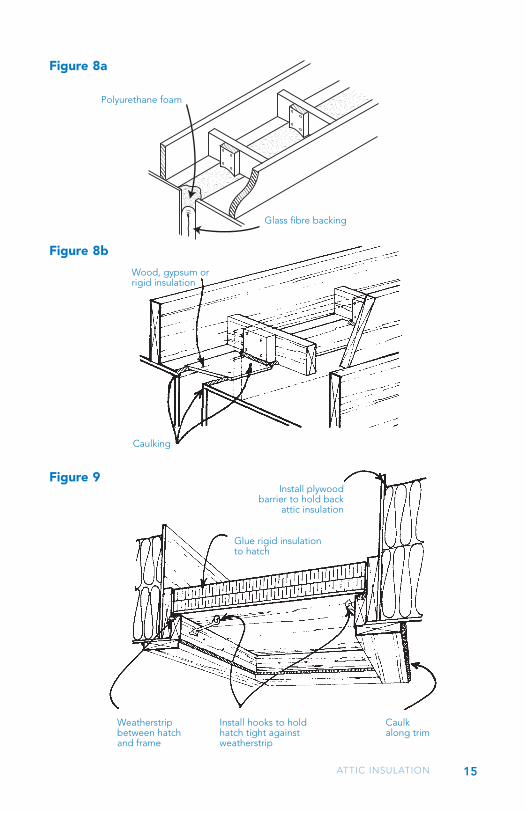
• At the top of interior and exterior walls -Wall cavities open to the attic represent gross air leakage and can be sealed by two methods.
1. Stuff a short piece (150 mm) of batt insulation into the wall cavity, leaving it approximately 50 to 75 mm below the ceiling level. Spray foam on the batt, filling the cavity with a slight overlap onto the ceiling material (Figure 8a).
2. Run a bead of construction adhesive on either side of the opening and place wood, gypsum sheathing, or rigid insulation over the opening. Seal the edges of the sheathing to the ceiling and wood ceiling joists (Figure 8b).
• Around attic hatches — Weatherstrip the hatch as you would a door to the outside, as shown in Figure 9. Use latches to hold the hatch snugly against the weatherstripping. Caulk around the ceiling trim of the hatchway.
Figure 7
Wrap ductwork with insulation
exhaust fan unit
Tape joints in ductwork with foil tape
Caulk junction of box and ceiling
15ATTIC INSULATION
Figure 8a
Figure 8b
Wood, gypsum orrigid insulation
Caulking
Install plywood barrier to hold back
attic insulation
Glue rigid insulation to hatch
Weatherstrip between hatch and frame
Install hooks to hold hatch tight against weatherstrip
Caulk along trim
Figure 9
polyurethane foam
glass �bre backing
Polyurethane foam
Glass fibre backing
16 BOOKLET #3
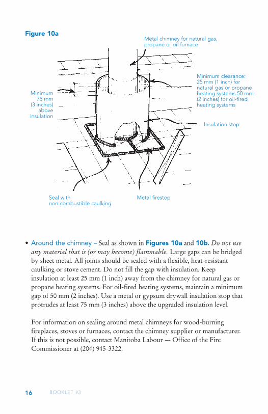
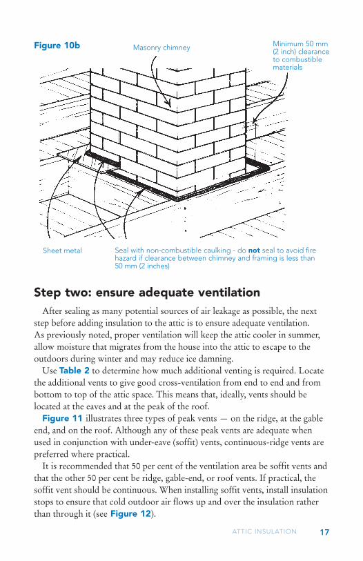
• Around the chimney – Seal as shown in Figures 10a and 10b. Do not use any material that is (or may become) flammable. Large gaps can be bridged by sheet metal. All joints should be sealed with a flexible, heat-resistant caulking or stove cement. Do not fill the gap with insulation. Keep insulation at least 25 mm (1 inch) away from the chimney for natural gas or propane heating systems. For oil-fired heating systems, maintain a minimum gap of 50 mm (2 inches). Use a metal or gypsum drywall insulation stop that protrudes at least 75 mm (3 inches) above the upgraded insulation level.
For information on sealing around metal chimneys for wood-burning fireplaces, stoves or furnaces, contact the chimney supplier or manufacturer. If this is not possible, contact Manitoba Labour --- Office of the Fire Commissioner at (204) 945-3322.
Figure 10a
Minimum 75 mm
(3 inches) above
insulation
Metal firestopSeal with non-combustible caulking
Insulation stop
Minimum clearance:25 mm (1 inch) for natural gas or propane heating systems 50 mm (2 inches) for oil-fired heating systems
Metal chimney for natural gas, propane or oil furnace
17
Step two: ensure adequate ventilationAfter sealing as many potential sources of air leakage as possible, the next
step before adding insulation to the attic is to ensure adequate ventilation. As previously noted, proper ventilation will keep the attic cooler in summer, allow moisture that migrates from the house into the attic to escape to the outdoors during winter and may reduce ice damning.
Use Table 2 to determine how much additional venting is required. Locate the additional vents to give good cross-ventilation from end to end and from bottom to top of the attic space. This means that, ideally, vents should be located at the eaves and at the peak of the roof.
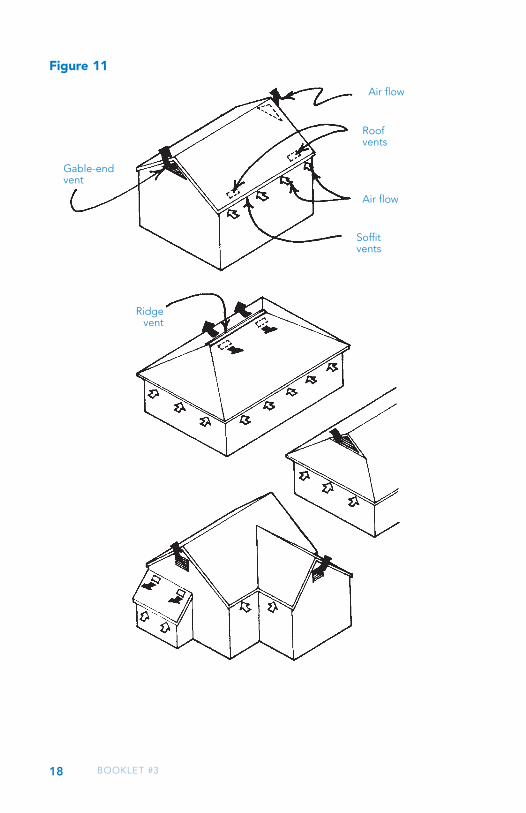
Figure 11 illustrates three types of peak vents — on the ridge, at the gable end, and on the roof. Although any of these peak vents are adequate when used in conjunction with under-eave (soffit) vents, continuous-ridge vents are preferred where practical.
It is recommended that 50 per cent of the ventilation area be soffit vents and that the other 50 per cent be ridge, gable-end, or roof vents. If practical, the soffit vent should be continuous. When installing soffit vents, install insulation stops to ensure that cold outdoor air flows up and over the insulation rather than through it (see Figure 12).
Figure 10b
Sheet metal Seal with non-combustible caulking - do not seal to avoid fire hazard if clearance between chimney and framing is less than 50 mm (2 inches)
Masonry chimney Minimum 50 mm (2 inch) clearance to combustible materials
ATTIC INSULATION
18 BOOKLET #3
Figure 11
Air flow
Roof vents
Air flow
Soffitvents
Gable-end vent
Ridgevent

19ATTIC INSULATION
Some houses (especially older ones) will have been built so that no air can flow between the soffits and the attic space. In this case, roof vents located near the perimeter of the house can be substituted for soffit vents (see Figure 11).
Turbine or fan-powered attic vents are generally not recommended in our climate. Although these types of vents may keep an attic cooler in summer, the large amount of air they exhaust can create a negative pressure in the attic. During winter, this negative pressure may draw warm, moist air from the house and into the attic. If excessive, this moisture can damage the attic framing, insulation, and ceiling finish.
If your home has limited attic space or a cathedral ceiling, ensuring adequate ventilation becomes much more difficult. In these cases, it is recommended that you discuss ventilation options with an insulation contractor and your local building authority.
Figure 12
Soffit vent
Air flow
Exterior wall
Insulation stop
Attic insulation
Roof
20 BOOKLET #3
After sealing potential sources of air leakage and ensuring adequate ventilation, the final step in retrofitting your attic is to add insulation.
The next few pages will help you to understand the techniques of adding insulation, whether you are doing the job yourself or just want to make sure the contractor you’ve hired is doing it properly.
Accessible atticsThe most common types of insulation material for use in an accessible attic
space (see Figure 1 on page three) are batt types or loose fill insulation. To choose the insulation type most appropriate to your situation, refer to Table 1 — Insulation Summary (pages 30 to 37) for guidance.
In some circumstances it may be desirable to use a combination of insulation types (when compatible). If there are a lot of obstructions above the joists in the attic, it may be easiest to put batt insulation into the joist spaces and then use loose fill to create a complete blanket of insulation above the joists and around all the obstructions. If some loose fill already partially fills the joist spaces, or if the joist spaces are irregular or obstructed, it may be easiest to fill the joist spaces to the top with loose fill, and then add a layer of batt insulation crosswise on top of the joists.
Installing batt type insulation
If you choose to install batt type insulation, the following guidelines should be observed:• Purchase the batts in a width to match the spacing of the attic framing.• Open the bags containing the batts in the attic rather than in the house to
reduce handling. The batts will significantly expand in size when released from the bags.
• The first layer of batts should be thick enough to completely fill the joist spaces. The second layer can then run in the opposite direction to completely cover the joists (see Figure 13).
• To prevent air movement from reducing the effectiveness of the insulation, ensure that there are no gaps between adjacent batts.
Insulating the attic

21ATTIC INSULATION
• Cut the batts with a utility knife and metal straightedge to the exact size required. Do not fold or compress the insulation to make it fit; this reduces the insulating value.
• Fill any awkward spaces or gaps with pieces of batts or with loose fill insulation.
Figure 13
Run second layer of batts perpendicular to first layer
Completely fill joist spaces with batts
Avoid gaps between adjacent batts

22 BOOKLET #3
Installing loose fill insulation
If you choose to install loose fill insulation, the following guidelines should be observed:• Pour the loose fill insulation on top of the existing insulation. Level the
insulation with a board or garden rake (see Figure 14).• If the insulation is being added to a depth greater than the height of the
joists, the extra thickness makes levelling a bit difficult but it will be worth it. Nail wood lath to the side of some of the joists to help you gauge the depth of the insulation. Maintain an even depth throughout the attic.
• If the loose fill insulation is deeper than the joists, build a crib around the attic hatch into the attic so that it can be filled to the edge (refer back to Figure 9 on page 15).
• If you choose to use cellulose loose fill insulation, you may find it more convenient to blow in the insulation rather than pouring it. Blowing equipment can often be rented from your insulation supplier for a nominal charge. Make sure the supplier explains how to operate this equipment properly.
Figure 14
Use markers to gauge depth of insulation
Level loose fill insulation with a garden rake or board
23ATTIC INSULATION
Additional points when insulating
The following points are applicable whether you use batt or loose fill insulation:• The insulation should extend as far as possible toward the eave. Caution
must be taken to keep the insulation from blocking ventilation openings and/or falling into the eave space. Insulation chutes, constructed of waxed cardboard, polystyrene, or PVC, can be used. The chutes fit between the rafters to provide an air space between the insulation and the roof sheathing.
• Don’t forget to insulate the hatch into your attic. Use glued-on rigid insulation or batt insulation held in place with cloth or burlap to an insulation level of at least RSI-3.5 (R-20) (refer back to Figure 9 on page 15).
• Do not cover heat sources, such as exhaust fans, with insulation unless you are certain they are approved to be covered; the heat build-up may create a fire hazard.
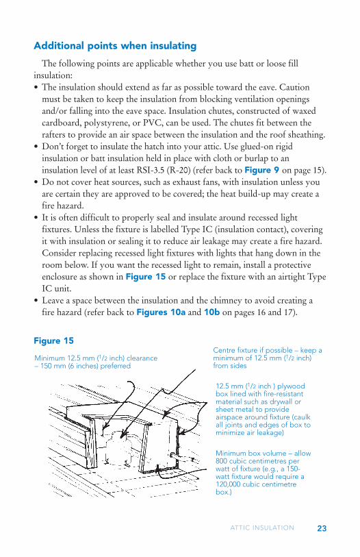
• It is often difficult to properly seal and insulate around recessed light fixtures. Unless the fixture is labelled Type IC (insulation contact), covering it with insulation or sealing it to reduce air leakage may create a fire hazard. Consider replacing recessed light fixtures with lights that hang down in the room below. If you want the recessed light to remain, install a protective enclosure as shown in Figure 15 or replace the fixture with an airtight Type IC unit.
• Leave a space between the insulation and the chimney to avoid creating a fire hazard (refer back to Figures 10a and 10b on pages 16 and 17).
Figure 15Centre fixture if possible – keep a minimum of 12.5 mm (1/2 inch) from sides
Minimum 12.5 mm (1/2 inch) clearance – 150 mm (6 inches) preferred
12.5 mm (1/2 inch ) plywood box lined with fire-resistant material such as drywall or sheet metal to provide airspace around fixture (caulk all joints and edges of box to minimize air leakage)
Minimum box volume – allow 800 cubic centimetres per watt of fixture (e.g., a 150-watt fixture would require a 120,000 cubic centimetre box.)

24 BOOKLET #3
Storey-and-a-half atticsThis type of attic can be difficult to retrofit. Insulation is applied to the
outer attic floor, walls and ceiling of the attic, as shown in Figure 16.
Outer attic floor and attic ceiling
• To prevent warm air from bypassing the insulation, block and seal the joist spaces under the knee wall with an impermeable rigid insulation and caulking (see Figure 17).
• Seal and insulate the outer attic floor and attic ceiling as described for accessible attics on the previous pages.
Figure 16Attic ceiling
Sloped ceiling
Knee wall
Outer attic floor

25ATTIC INSULATION
Knee walls
• Seal any obvious air leaks and then place batt insulation between the knee wall studs (see Figure 17).
• If the studs are 89 mm (31/2 inches) deep, use a single layer of RSI-2.1 (R-12) insulation vertically between the studs and another layer horizontally behind the studs. Support the second layer of insulation with 19 x 64 mm (1 x 3 inches) framing nailed to each rafter.
To increase the effectiveness of the insulation, place a housewrap material (Tyvek, Typar or similar) on the back side of the insulation. The housewrap should be secured to the rafters and held in place by the 1 x 3 framing.
Figure 17
Knee wall framing
19 x 64 mm (1 x 3 inches) framing to support second layer of batt insulation
Second layer of batt insulation behind knee wall framing
Batt or loose fill insulation in outer attic floor
Floor joist
Rigid insulationCaulking
Batt insulation between knee
wall framing
Caulk along baseboard

26 BOOKLET #3
End walls
• The end walls can be insulated in several different ways; another publication in this series, entitled Booklet #4: Wall insulation, provides details.
Sloped ceilings
• Sloped sections of the ceiling can be strapped, insulated and covered with a new air-vapour barrier as shown in Figure 18. Two layers of strapping at right angles can be used to attain a higher level of insulation and to reduce “thermal bridges” through the wood strapping (wood has a lower resistance to heat flow than insulation).
Figure 18
Sloped ceiling
End wall
Rigid insulation (place between each layer of strapping)
Wood strapping (install second layer perpendicular to first)
Knee wall Cover strapping and insulation with continuous air-vapour barrier and 13 mm (1/2 inch) drywall
27ATTIC INSULATION
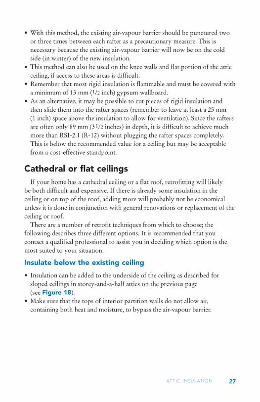
• With this method, the existing air-vapour barrier should be punctured two or three times between each rafter as a precautionary measure. This is necessary because the existing air-vapour barrier will now be on the cold side (in winter) of the new insulation.
• This method can also be used on the knee walls and flat portion of the attic ceiling, if access to these areas is difficult.
• Remember that most rigid insulation is flammable and must be covered with a minimum of 13 mm (1/2 inch) gypsum wallboard.
• As an alternative, it may be possible to cut pieces of rigid insulation and then slide them into the rafter spaces (remember to leave at least a 25 mm (1 inch) space above the insulation to allow for ventilation). Since the rafters are often only 89 mm (31/2 inches) in depth, it is difficult to achieve much more than RSI-2.1 (R-12) without plugging the rafter spaces completely. This is below the recommended value for a ceiling but may be acceptable from a cost-effective standpoint.
Cathedral or flat ceilingsIf your home has a cathedral ceiling or a flat roof, retrofitting will likely
be both difficult and expensive. If there is already some insulation in the ceiling or on top of the roof, adding more will probably not be economical unless it is done in conjunction with general renovations or replacement of the ceiling or roof.
There are a number of retrofit techniques from which to choose; the following describes three different options. It is recommended that you contact a qualified professional to assist you in deciding which option is the most suited to your situation.
Insulate below the existing ceiling
• Insulation can be added to the underside of the ceiling as described for sloped ceilings in storey-and-a-half attics on the previous page (see Figure 18).
• Make sure that the tops of interior partition walls do not allow air, containing both heat and moisture, to bypass the air-vapour barrier.

28 BOOKLET #3
Insulate above the existing roof
• If your home has an open beam ceiling which you would like to retain, it may be feasible to add insulation on top of the existing roof deck as shown in Figure 19, or use rigid insulation.
Figure 19
Frame to provide 89 mm (3 1/2 inch) air
space above insulation
Air-vapour barrier
New insulation layer (RSI value must be at least equal to that of existing roof insulation)
Existing roof and insulation (remove shingles)Existing soffit
(remove and block existing ventilation space at soffit and ridge)
New soffit with continuous venting
Blocking
Continuous ridge vent
New sheathing and shingles
29ATTIC INSULATION
• The existing roof finish should be removed to allow for good contact between the insulation and the surface to which it is being applied. If the existing air-vapour barrier is not in good condition, a new one should be placed over the roof as shown.
• Any ventilation in the existing roof structure must be blocked. A new insulation layer with a RSI (R-value) of at least equal to that of the existing roof insulation can then be added. The new insulation can be either batt or rigid type.
• Adequate ventilation (usually continuous soffit and ridge vents) above the new insulation layer should be provided. The roof can then be sheathed and a new finish applied.
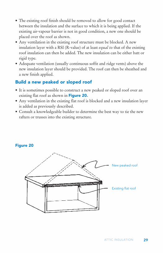
Build a new peaked or sloped roof
• It is sometimes possible to construct a new peaked or sloped roof over an existing flat roof as shown in Figure 20.
• Any ventilation in the existing flat roof is blocked and a new insulation layer is added as previously described.
• Consult a knowledgeable builder to determine the best way to tie the new rafters or trusses into the existing structure.
Figure 20
New peaked roof
Existing flat roof
30 BOOKLET #3
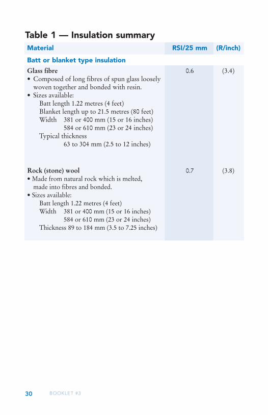
Table 1 — Insulation summary
Glass fibre 0.6 (3.4)• Composed of long fibres of spun glass loosely
woven together and bonded with resin.• Sizes available: Batt length 1.22 metres (4 feet) Blanket length up to 21.5 metres (80 feet) Width 381 or 400 mm (15 or 16 inches) 584 or 610 mm (23 or 24 inches) Typical thickness
63 to 304 mm (2.5 to 12 inches)
Material RSI/25 mm (R/inch)
Batt or blanket type insulation
Rock (stone) wool 0.7 (3.8)• Made from natural rock which is melted,
made into fibres and bonded.• Sizes available: Batt length 1.22 metres (4 feet) Width 381 or 400 mm (15 or 16 inches) 584 or 610 mm (23 or 24 inches) Thickness 89 to 184 mm (3.5 to 7.25 inches)

31ATTIC INSULATION
• easy to install in standard joist and stud spaces,• dries with little effect if exposed
to moisture,• low cost,• some products are non-
combustible; (check with manufacturer),
• lightweight,• non-settling.
• easy to install in standard joist and stud spaces,
• highly resistant to fire,• dries with little effect if exposed to
moisture,• moderate cost,• can be used as insulation and
drainage layer around foundations.
• does not fit readily into uneven spaces,
• can irritate the eyes, skin and respiratory system during installation,
• little resistance to air leakage.
• mild skin irritant during application,• little resistance to air leakage,• difficult to fill irregular spaces.
Advantages Limitations

32 BOOKLET #3
Cellulose fibre 0.6 (3.6)• Manufactured from finely shredded
newsprint with chemicals mixed in to resist fire and fungal growth
Glass fibre 0.5 (2.9)• Similar material to glass fibre batts but
chopped up for blowing purposes
Vermiculite* 1.6 (2.3)• Mica material that has been expanded by a
high temperature steam process;• Light brown/grey/gold in colour and is a
pebble-like material ranging in size from 2 – 10 millimeters in diameter;
• Vermiculate installed prior to 1990 is likely to contain asbestos.
Note: Existing vermiculite should be handled with care.
Wood shavings 0.4 (2.5)• By-product of wood industries, shavings are
often mixed with lime and other chemicals.
Material RSI/25 mm (R/inch)
Loose fill insulation
* For more details on vermiculite insulation, check out the Safe Manitoba bulletin available from Manitoba Workplace Safety and Health or online at safemanitoba.com/bulletins.aspx

33ATTIC INSULATION
Advantages Limitations
• easily fills irregular spaces,• has a higher resistance to air
leakage than other loose fill insulations,
• low cost,• recycles newspaper,• may be blown into closed
cavities (i.e., walls).
• easily fills irregular spaces,• has a light weight for its RSI-value,• some products are
non-combustible, check with manufacturer,
• low cost,• may be blown into closed cavities
(i.e., walls).
• easiest loose fill insulation to fill irregular spaces,
• highly resistant to fire.
• usually low cost if locally produced,
• recycles wood waste.
• permanently damaged if exposed to excessive moisture,
• should not be installed in contact with high-temperature sources (e.g. chimney, recessed lights, etc.),
• should not be covered with heavier types of insulation which may compress it,
• eye and respiratory system irritant during installation,
• may settle.
• can irritate the eyes, skin and respiratory system during installation,
• little resistance to air leakage,• may settle,• should not be covered with heavier
insulation materials.
• moderate cost,• absorbs moisture and dries slowly,• low RSI-value per unit thickness,• may settle.
• difficult to treat against fire, vermin and fungus growth,
• absorbs moisture and dries slowly,• should not be installed in contact with
high-temperature sources (e.g. chimney, recessed lights, etc.),
• low RSI-value per unit thickness,• may settle.

34 BOOKLET #3
Material RSI/25 mm (R/inch)
Rigid board insulation
Expanded polystyrene (“beadboard”) Low density (3.6)Type 1 & 2 0.6• Produced by a process that results in beads
containing air, bonded together into rigid, High density (4.0) foam plastic boards. 0.7
• Sizes available: Length 1.2 or 2.4 metres (4 or 8 feet) Width 406, 610 or 1220 mm (16, 24 or 48 inches) Thickness 19 to 152 mm (3/4 to 6 inches)
Extruded polystyrene 0.9 (5.0)Type 3 & 4• A foam plastic board composed of fine,
closed cells containing a mixture of air and refrigerant gases (fluorocarbons).
• Sizes available: Length 1.2 or 2.4 metres (4 or 8 feet) Width 406, 610 or 1220 mm (16, 24 or 48 inches) Thickness 19 to 152 mm (3/4 to 6 inches)
Polyisocyanurate boards 4.2 (6.0) 1.1 (6.0)• A foam plastic board with primarily closed
cells filled with refrigerant gases (fluorocarbons).
• Usually foil-faced on both sides to strengthen the board and retain the gases which give it a high RSI-value.
• Sizes available: Length 2.4 metres (8 feet)
Width 1.2 metres (4 feet) Thickness 25-100 mm (1-4 inches)
35ATTIC INSULATION
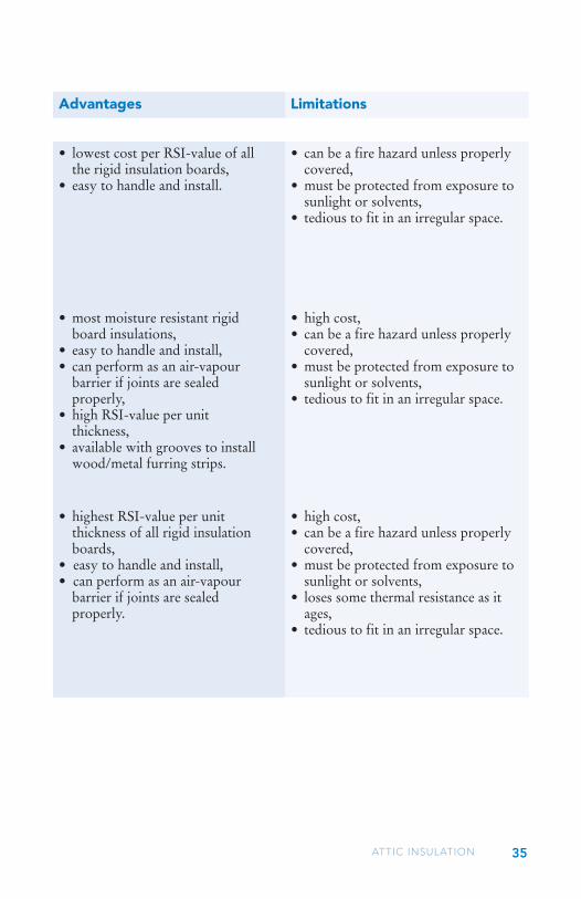
Advantages Limitations
• lowest cost per RSI-value of all the rigid insulation boards,
• easy to handle and install.
• most moisture resistant rigid board insulations,
• easy to handle and install, • can perform as an air-vapour
barrier if joints are sealed properly,
• high RSI-value per unit thickness,
• available with grooves to install wood/metal furring strips.
• highest RSI-value per unit thickness of all rigid insulation boards,
• easy to handle and install,• can perform as an air-vapour
barrier if joints are sealed properly.
• can be a fire hazard unless properly covered,
• must be protected from exposure to sunlight or solvents,
• tedious to fit in an irregular space.
• high cost, • can be a fire hazard unless properly
covered,• must be protected from exposure to
sunlight or solvents,• tedious to fit in an irregular space.
• high cost, • can be a fire hazard unless properly
covered,• must be protected from exposure to
sunlight or solvents,• loses some thermal resistance as it
ages,• tedious to fit in an irregular space.

36 BOOKLET #3
Material RSI/25 mm (R/inch)
Spray/blow in place insulation
Spray polyurethane foam Low density (3.7)• A semi-flexible plastic foam manufactured on 0.7
site using 2 liquid components; Medium density (6.0)• Liquids are pumped through a hose and 1.1
sprayed in place where it cures through a chemical reaction.
Cellulose 0.7 (3.8)• Made from paper or paper board stock
with chemical additives for fire and fungal resistance;
• Sprayed with water into a cavity to form a cohesive mat.
Glass fibre 0.7 (3.9)• Loose, glass fibre insulation, incorporating a
water-activated adhesive;• The dry insulation is misted with water and
installed using a blowing machine.
37ATTIC INSULATION
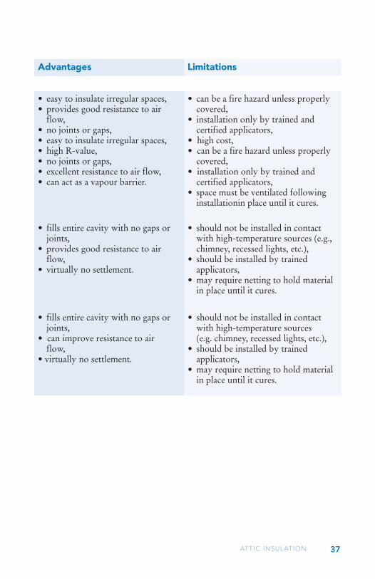
Advantages Limitations
• easy to insulate irregular spaces,• provides good resistance to air
flow,• no joints or gaps,• easy to insulate irregular spaces,• high R-value,• no joints or gaps,• excellent resistance to air flow,• can act as a vapour barrier.
• fills entire cavity with no gaps or joints,
• provides good resistance to air flow,
• virtually no settlement.
• fills entire cavity with no gaps or joints,
• can improve resistance to air flow,
• virtually no settlement.
• can be a fire hazard unless properly covered,
• installation only by trained and certified applicators,
• high cost,• can be a fire hazard unless properly
covered,• installation only by trained and
certified applicators,• space must be ventilated following
installationin place until it cures.
• should not be installed in contact with high-temperature sources (e.g., chimney, recessed lights, etc.),
• should be installed by trained applicators,
• may require netting to hold material in place until it cures.
• should not be installed in contact with high-temperature sources (e.g. chimney, recessed lights, etc.),
• should be installed by trained applicators,
• may require netting to hold material in place until it cures.

BOOKLET #3

The information contained herein is published as a convenient reference for Manitoba Hydro’s customers. While every effort has been made to provide accurate and complete information, Manitoba Hydro does not warrant the accuracy or efficacy thereof. Manitoba Hydro will not be liable for any loss, costs, damage or injury whatsoever, resulting from the use of this material.
Cette information est également disponible en français.
Metric Conversion Factors A. Converting Imperial Units into Metric Units Unit Conversion Multiply By Thermal Resistance R values to RSI values 0.1761
Length inches to millimetres 25.40 inches to centimetres 2.540 feet to metres 0.3048
Area square feet to square metres 0.09290
Volume gallons to litres 4.546 cubic feet to cubic metres 0.02832
Mass pounds to kilograms 0.4536
Density pounds/cubic feet to kilograms/cubic metre 16.02
B. Converting Metric Units into Imperial Units Unit Conversion Multiply By Thermal Resistance RSI values to R values 5.678
Length millimetres to inches 0.03937 centimetres to inches 0.3937 metres to feet 3.281
Area square metres to square feet 10.76
Volume litres to gallons 0.2200 cubic metres to cubic feet 35.31
Mass kilograms to pounds 2.205
Density kilograms/cubic metre to pounds/cubic foot 0.06243
If you are uncertain of, or have any question or concern regarding, any subject matter herein or the safety and/or proper handling of any material(s) and/or product(s) that you may encounter in your undertaking, please consult resources such as Health Canada (Health Links) @ 1-888-315-9257, the Manitoba Department of Labour @ 1-800-282-8069, or (Canada Mortgage & Housing Corp.) @ 1-800-668-2642.

PSG3 - 0714