Embed Size (px)
Citation preview

Energy Storage as a Key Element in Smart Grids
Ross Baldick, Department of Electrical and
Computer Engineering
1Copyright © 2019
Bill Muston
Oncor
Spring 2019WEM Draft in Process

ONCOR
• 3.4+ M customers
• Largest regulated utility in
Texas
• 4000 employees
• Transmission
• Distribution
• Metering
• Interconnections
Regulated, investor-owned, wires utility in ERCOT –does not generate, own, or sell electricity
– but delivers it –

3
Scope & Disclaimer
This presentation is intended to be broad in
scope about the range of energy storage
system (ESS) applications in the power grid.
The applications and examples cited in this
presentation are not limited to the particular
types of applications of direct interest to
Oncor as a regulated utility within the market
structure and regulatory rules that apply to
Oncor.

4
Acknowledgements
Thanks to Oncor for allowing the use of
slides and knowledge.
Thanks to Nathan Kassees and Mila Hunt at
Oncor for partnership in developing the
content, slides, and homework for the
original 2017 presentation.

Outline
◼ Why Now?
◼ Energy Storage System (ESS) – Definition
◼ Roles – Bulk Power, Wires, Customer, DER
◼ Utility Distribution Systems
◼ Meet reliability needs
◼ Serve growing demand
◼ Microgrids
◼ Multiple uses of a single ESS
◼ Regulatory & market construct considerations
5Copyright © 2019

Outline
◼ Why Now?
◼ Energy Storage System (ESS) – Definition
◼ Roles – Bulk Power, Wires, Customer, DER
◼ Utility Distribution Systems
◼ Meet reliability needs
◼ Serve growing demand
◼ Microgrids
◼ Multiple uses of a single ESS
◼ Regulatory & market construct considerations
6Copyright © 2019

THEMES
7
Costs are declining
Experience is growing
Storage opens up new ways
to address grid needs
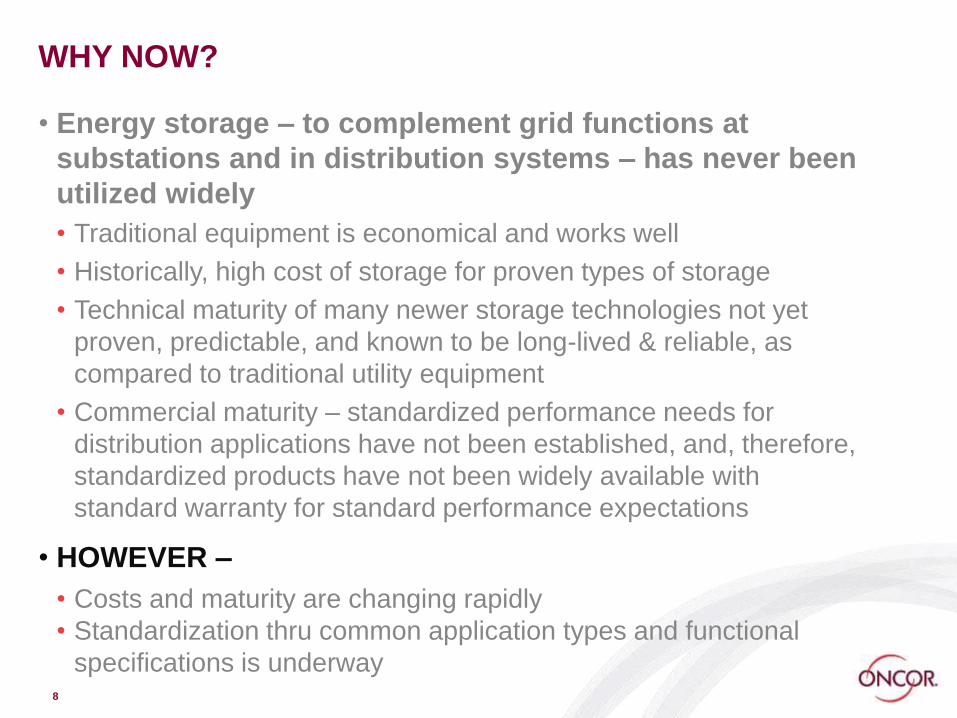
WHY NOW?
• Energy storage – to complement grid functions at
substations and in distribution systems – has never been
utilized widely
• Traditional equipment is economical and works well
• Historically, high cost of storage for proven types of storage
• Technical maturity of many newer storage technologies not yet
proven, predictable, and known to be long-lived & reliable, as
compared to traditional utility equipment
• Commercial maturity – standardized performance needs for
distribution applications have not been established, and, therefore,
standardized products have not been widely available with
standard warranty for standard performance expectations
• HOWEVER –
• Costs and maturity are changing rapidly
• Standardization thru common application types and functional
specifications is underway8

TYPES OF ENERGY STORAGE
9
Energy storage takes many forms:
(a) electro-chemical batteries;
(b) chemical flow batteries;
(c) electrical potential storage, such as capacitors;
(d) mechanical inertia, such as flywheels; and
(e) potential energy, such as compressed air storage, liquid
air storage, and pumped hydro
The choice of type of storage will be affected by the particular
application and by commercial maturity
Lithium-Ion batteries have become the cost and deployment
leader
Technical advancement of storage continues at a rapid pace
throughout the world
For ‘smart grid’ applications, the discussion will be mainly about batteries, due to their present cost and deployment ease today

Lithium-Ion Battery
Oncor Confidential - For Internal Use Only10
Anode - Copper conductor in Carbon, Titanium-
Oxide, or Silicon-Tin structure
1 - Lithium Ions release electrons and dissolve into
electrolyte
4 - Lithium Ions combine with electrons and layer
onto anode
Cathode - Lithium-Metal-Oxide or Lithium-Metal-
Phosphate structure
2 - Lithium Ions combine with electrons and
integrate with cathode
3 - Lithium Ions release electrons and dissolve into
electrolyte
ElectrolyteLiquid or Gel electrolyte of Lithium-Carbonate or
Lithium-Flouride Compound
Conductive to Lithium Ions (Li+)
Polymer Hydrocarbon barrier conductive to Lithium Ions
(Li+)

COST DISCUSSION
•Costs for Li-Ion have
declined rapidly
•Double-digit % cost
reduction for several
years
•Battery pack (dc) costs
have declined ~80% from
2010 to 2018
•Progress in balance of
plant costs
• Scale of manufacturing
• Maturity of manufacturing
processes
• Supply chain economies
• The # of manufacturers &
production lines
11
0
200
400
600
800
1000
1200
1 2 3 4 5

ELEMENTS OF COST
• Component Level
• Storage mechanism – eg. battery cells, packs, racks
• Power conversion ac/dc/ac
• Container – weight, footprint, safety, environmental
• Controls & monitoring
• Macro Level
• By type of application
• $’s / kW
• $’s / kWh
12
Recommended:
EPRI Energy Storage Cost Analysis:
Executive Summary
Technical Report 3002013958,
December 2018
The challenge of stating costs versus the desire for
simple comparisons among types & applications
Outline
◼ Why Now?
◼ Energy Storage System (ESS) – Definition
◼ Roles – Bulk Power, Wires, Customer, DER
◼ Utility Distribution Systems
◼ Meet reliability needs
◼ Serve growing demand
◼ Microgrids
◼ Multiple uses of a single ESS
◼ Regulatory & market construct considerations
13Copyright © 2019

ENERGY STORAGE SYSTEM – ESS
• Energy stored in a form other than AC electricity
• Energy storage unit is ‘filled’ with energy from the grid
• Conversion from AC to stored energy and back to AC
• Grid tie & interface equipment and controls
• Internal storage unit internal controls to protect the asset
• Often called Battery Management System (BMS)
• A set of equipment that can be ‘placed’
• As used in these slides, an ESS is NOT locationally tied uniquely such
as pumped hydro or compressed air energy storage where siting is
driven by geology
14

BATTERY STORAGE SYSTEMS
15
Battery cell
Inverter
Grid
Electric Customer
BMS Controls
ESS Controls
Battery rack
Battery Array
Switch
Transformer

DESIGN FLEXIBILITY & CHOICES
•Power: Charge-discharge
•Energy: How much
•Rapid charge-discharge
➔ High C-rate
•Power conversion system
(inverter)
•Container & systems
•Grid transformer &
SCADA
•Site meteorological
•Site layout
• Efficiency –
• Life – cycles & shelf life
16
www.kaplanco.com
kWhAC out / kWhAC in
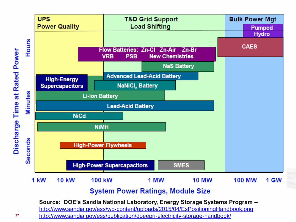
17
Source: DOE’s Sandia National Laboratory, Energy Storage Systems Program –
http://www.sandia.gov/ess/wp-content/uploads/2015/04/EsPositioningHandbook.png
http://www.sandia.gov/ess/publication/doeepri-electricity-storage-handbook/

18
Growing dominance of Li-Ion
Will it continue?
Lithium-ion batteries have achieved a cost, performance, and speed-of-deployment advantage today, which has led to their dominance in energy storage deployments the last few years.

Outline
◼ Why Now?
◼ Energy Storage System (ESS) – Definition
◼ Roles – Bulk Power, Wires, Customer, DER
◼ Utility Distribution Systems
◼ Meet reliability needs
◼ Serve growing demand
◼ Microgrids
◼ Multiple uses of a single ESS
◼ Regulatory & market construct considerations
19Copyright © 2019

BATTERY
TRANSMISSIONGENERATION
RETAIL ELECTRIC
PROVIDERS
DISTRIBUTION LINES
CompetitiveRegulated

GRID ENERGY STORAGE VALUES
21
BULK GRID
Wind & solar firming, smoothing and dispatch
Time-shift energy supply vs. need to meet market needs
Grid reliability services
• Supply regulation• Frequency regulation• Responsive reserves for
grid contingency• Fast response
Time-shift to address transmission constraint
DISTRIBUTION FEEDERS &
SUBSTATION
Support the local grid during upstream outages
Defer or substitute for traditional upgrades needed to support growing loads
Integrate distributed energy resources (DERs) to the local grid to maintain local grid stability & voltage control
Extend local operations with feeder-segment microgrids
CUSTOMER
Manage customer peak demand to limit demand charges
Smooth & firm customer-sited solar or wind
Time-shift energy from the grid or from customer-sited solar, such as to manage energy use under a time-of-use retail rate
Support islanded microgrid operation for critical services during grid outage
Focus of this lecture

http://www.nytimes.com/2010/11/07/us/07ttbattery.html
Electric Transmission Texas energy
storage project in Presidio, Texas.
• Commercial operation in 2010
• Serving transmission purposes
• http://www.ettexas.com/projects/presnas.asp
Slide compiled by Oncor from public sources

23

24 Slide compiled by Oncor from public sources

PUBLIC
Existing ERCOT Energy Storage Resources Projects
Type/Name County MW ~On-line dateSodium Sulfur/ Presidio [Non-Market] Presidio 4 Q1 2010
LI/ NWF Ector/Winkler 36 Q4 2012
LI/ OCI_ALM1 Bexar 1 Q1 2016LI/ BLSUMMIT Wilbarger 30 Q3 2017LI/ TOSBATT Howard 2 Q4 2017LI/ PYR Nolan 10 Q1 2018LI/ INDL Nolan 10 Q1 2018Total 93
25

PUBLIC
ERCOT Energy Storage Resources Projects(per the GINR Project Details (as of 9-30-18) [Partial List]
Planned **:
* COD from Interconnect Request
** Does not include a few Planned Resources 10 MW or less
26
Project Name County MW Projected CODMillhouse Storage Jim Wells 38 11/15/2019
Chisholm Grid Battery Storage Tarrant 200 03/01/2020
Longbow Storage Brazoria 35 03/01/2020
Angus Storage Bosque 63 08/31/2020
Stillwater Storage Nueces 72 08/31/2020
Dusky Storage Hill 83 12/30/2020
Robles Storage Dimmit 100 12/31/2020
Prairie Point Battery Grayson 41 12/01/2020
Zier Storage Kinney 60 05/31/2021
El Zorro Storage Webb 125 02/01/2021
Green Holly Storage Dawson 50 08/01/2021
867
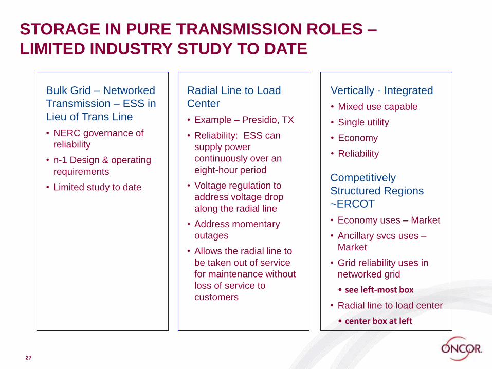
27
STORAGE IN PURE TRANSMISSION ROLES –
LIMITED INDUSTRY STUDY TO DATE
Bulk Grid – Networked
Transmission – ESS in
Lieu of Trans Line
• NERC governance of
reliability
• n-1 Design & operating
requirements
• Limited study to date
Radial Line to Load
Center
• Example – Presidio, TX
• Reliability: ESS can
supply power
continuously over an
eight-hour period
• Voltage regulation to
address voltage drop
along the radial line
• Address momentary
outages
• Allows the radial line to
be taken out of service
for maintenance without
loss of service to
customers
Vertically - Integrated
• Mixed use capable
• Single utility
• Economy
• Reliability
Competitively
Structured Regions
~ERCOT
• Economy uses – Market
• Ancillary svcs uses –
Market
• Grid reliability uses in
networked grid
• see left-most box
• Radial line to load center
• center box at left

DELIVERY OF POWER – SUBSTATIONS &
DISTRIBUTION
28

DISTRIBUTION SYSTEM USE CASES FOR ESS
• RELIABILITY – Supply local downstream loads when the
upstream power is out
• SERVE GROWING DEMAND – An asset to meet a portion
of growing local peak demand without requiring that
traditional upstream facilities, such as feeders and
substations, be upgraded to meet that demand
• INTEGRATE SOLAR – Maintain required feeder voltage &
power factor during rapid feeder power changes for
feeders with high solar penetration when clouds come
and go
29

Outline
◼ Why Now?
◼ Energy Storage System (ESS) – Definition
◼ Roles – Bulk Power, Wires, Customer, DER
◼ Utility Distribution Systems
◼ Meet reliability needs
◼ Serve growing demand
◼ Microgrids
◼ Multiple uses of a single ESS
◼ Regulatory & market construct considerations
30Copyright © 2019

31 Oncor Proprietary and Confidential - Not for external distribution
TODAY’S APPROACHES TO IMPROVE FEEDER
RELIABILITY
• Vegetation Management
• Feeder Maintenance
• Automation
• Autonomous communications and control
• Automated Feeder Switch
• Reclosing Fuses
• Faulted Circuit Indicator
• Fault Location, Isolation, Service Restoration/Reconfiguration
• Operations
• Outage Management Systems (OMS)
• Advanced Meter Systems (AMS) w outage notification

32
USING ENERGY STORAGE TO IMPROVE RELIABILITY
• Energy Storage System (ESS)
• Automation

DISTRIBUTION FEEDER – BASIS FOR DISCUSSION
33
CIRCUIT
BREAKER AT
SUBSTATION
Circuit Breaker
for Each Feeder
Protective
Relays
DISTRIBUTION FEEDER
Radial, not networked
Simplified diagram does not show
reclosers, capacitor banks, voltage
regulators and laterals
12.5 kV or 25 kV primary voltage at Oncor

34
Purpose
• Evaluate effectiveness of deploying small-scale battery storage to bridge outages and improve local power quality
Details
• Six 25 kW lithium ion batteries
• Installation, testing and monitoring
Capacity
• These batteries are capable of bridging outages up to a few hours of duration
NEIGHBORHOOD STORAGE RELIABILITY INITIATIVE
Deployed & operational by end of 2014

NEIGHBORHOOD STORAGE RELIABILITY INITIATIVE
Location Selection
120/240 Single Phase
Test Installation (SOSF)
South Dallas Target Area
High SAIDI Feeders
Customer Verbal Approval
Available Space
35
SAIDI = System Average Interruption Duration Index

ESS PLACED AT LOAD-SERVING TRANSFORMER
36
NO
NC
Transformer
Energy
Storage
System (ESS)
ONCOR NEIGHBORHOOD
STORAGE RELIABILITY
INITIATIVE (NSRI)
25 kW x 25 kWh
Discharge only to support
homes in a grid outage
Recharge only off system
peak
NC
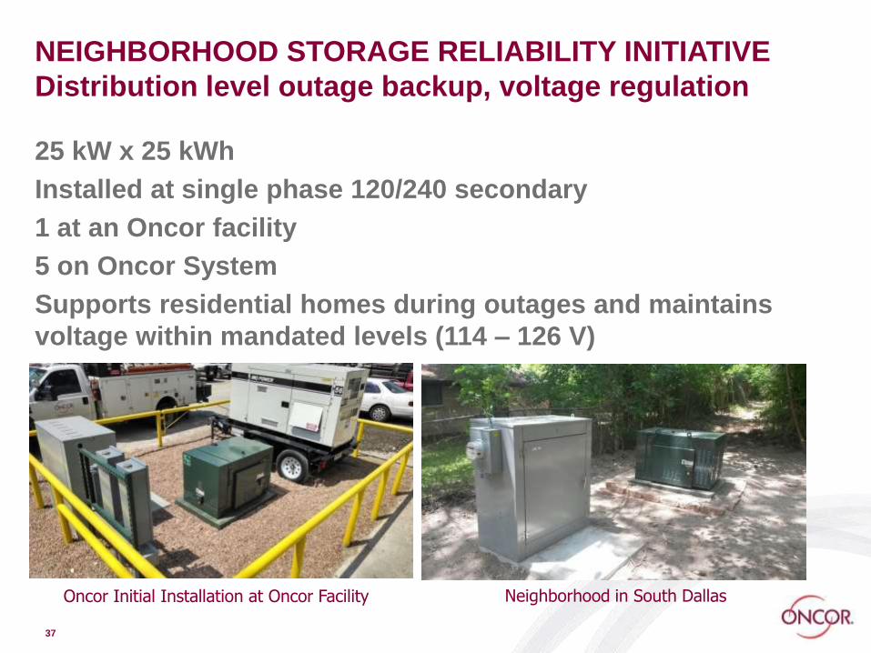
NEIGHBORHOOD STORAGE RELIABILITY INITIATIVE
Distribution level outage backup, voltage regulation
25 kW x 25 kWh
Installed at single phase 120/240 secondary
1 at an Oncor facility
5 on Oncor System
Supports residential homes during outages and maintains
voltage within mandated levels (114 – 126 V)
37
Oncor Initial Installation at Oncor Facility Neighborhood in South Dallas

Example: Outage
38
ESS
Tie
Breaker

Example: Outage
39
ESS
Tie
Breaker

Example: Outage
40
ESS
Tie
Breaker

Normal Switching Scheme
41
CES = Community Energy Storage

Bypass Switching Scheme
42
CES = Community Energy Storage
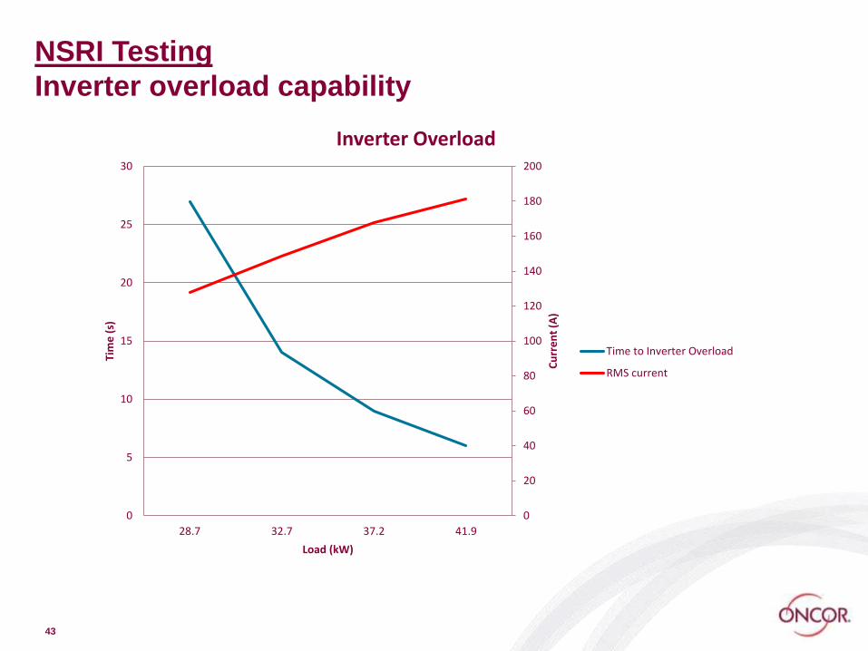
NSRI Testing
Inverter overload capability
43
0
20
40
60
80
100
120
140
160
180
200
0
5
10
15
20
25
30
28.7 32.7 37.2 41.9
Cu
rre
nt
(A)
Tim
e (
s)
Load (kW)
Inverter Overload
Time to Inverter Overload
RMS current

NSRI Testing
Open circuit island test
Oncor Confidential - For Internal Use Only44 Oncor Confidential - For Internal Use Only44
25.5 ms
Transition to
Inverter
Transition to
Grid
34.4 ms

NSRI Testing
25 kW Load Island Test
45
Transition to
Inverter
Transition to
Grid
26.7 ms
33.0 ms

NSRI Testing
Small Fridge Island Test (2 amp motor)
Oncor Confidential - For Internal Use Only46
26.0 ms
Transition to
Inverter
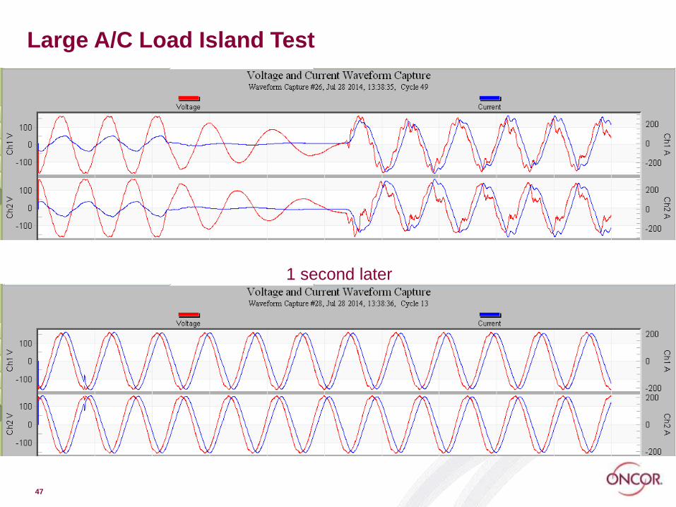
Large A/C Load Island Test
47
1 second later

Operational Settings
Based on ITI (CBEMA)
curve defining voltage
tolerance thresholds of
power supplies
NSRI islanding settings
based on this curve
48

NSRI Results: Inception to January 2019
Oncor Confidential - For Internal Use Only49
LocationNumber of Operations
Total Island Minutes Average CIM Efficiency
1 16 921 58 2763 95.1%
2 9 267 30 1068 98.9%
3 13 506 39 2024 98.0%
4 26 483 19 966 96.9%
5 7 428 61 1712 99.1%
All 71 2605 37 8533
Efficiency measured as energy in vs. energy out over the life of the system

DISTRIBUTION FEEDER – BASIS FOR DISCUSSION
50
CIRCUIT
BREAKER AT
SUBSTATION
Circuit Breaker
for Each Feeder
Protective
Relays
DISTRIBUTION FEEDER
Radial, not networked
Diagram is simplified and does not show
reclosers, capacitor banks, voltage
regulators and laterals
12.5 kV or 25 kV primary voltage at Oncor

SECTIONALIZE & BACKFEED TO IMPROVE
RELIABILITY (FLISR)
51
• Add sectionalizing to the feeder
• Connect end of feeder to nearby feeder
• Breaker opens and locks. Locate fault
• Open NC Normally Closed switch
• Close NO Normally Open switch to feed
healthy segment of the circuit
NC
NO

SECTIONALIZING & BACKFEED TO IMPROVE
RELIABILITY – TYPICAL INSTALLATION
52
• Capability to backfeed to either feeder
• Construction of tie between the two
• Adding 3 automated switches
• May also require some upgrade of circuit
to carry the added load
• Utilized in urban & suburban areas
NO
NC
NC

RURAL FEEDER – UTILIZE ESS VS BACKFEED
53
• Add sectionalizing
• Add storage downstream
• Size storage to support customers
for ~2 hours
• Allow time for crews to restore
power upstream
• Improve SAIDI on the feeder
ESS
• ESS must have grid-
forming capability
• Energy source
• Voltage & frequency
control
• Supply in-rush current
when initially restore
• Feeder is long
• Distance to another feeder for
backfeed is large
• Upper portion of feeder experiences
an outage (eg. local storm)
• All customers are out

ESS – REQUIREMENTS FOR FEEDER RELIABILITY
• Operate ESS only during a grid outage
• Designed to serve load ~2 hours during restoration of
grid ➔ increase reliability by improving SAIDI
• Brief outage – Wait until breaker locks out. Isolate
downstream load from upstream faulted grid with
sectionalizing switch. Start the ESS
• ESS designed to provide in-rush current
• ESS designed to support faults on the feeder to allow
existing fusing or other protective devices to work
• Inverter must be grid-forming
• Controller must maintain appropriate voltage & frequency
using only the ESS during this operation of a small
electrical island until upstream grid power is restored
54
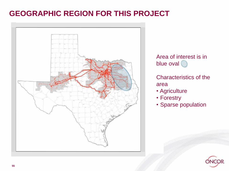
GEOGRAPHIC REGION FOR THIS PROJECT
55
Area of interest is in
blue oval
Characteristics of the
area
• Agriculture
• Forestry
• Sparse population

FEEDER SELECTION CRITERIA
1. Consistently high SAIDI
2. Majority of faults along feeder backbone
3. Ties to other feeders not easily accessible
4. Minimum of a few hundred customers
5. No heavy industrial customers
6. Feeder length >40 miles primary 3-phase
7. Pockets of load located toward the end of the line
56
SAIDI = System Average Interruption Duration Index

Feeder B
57
73 Miles of Primary Feeder
379 Customers
4.3 kW of load/meter avg
2.3 MW of peak load

Feeder B Battery Solution
58
c
c
Automated
Switches
S
S
S

2 mi
Install N/O IRPC with Intelliteam II.
Install N/C IRPC with Intelliteam II.
R
Install N/CNova Form 6 Recloser
R
Honey Grove Substation
29,000 ft. of 3-#2 ACSR reconductor/rebuild
R
Install N/C IRPC with Intelliteam II.
Install/Upgrade regulators/controls [3 locations]
Install N/O IRPC with Intelliteam II.
31,000 ft. of 3-#2 ACSR reconductor/rebuild
8,000 ft. of 3-#2ACSR reconductor/rebuild
R
Install N/CNova Form 6 Recloser
N
Feeder B Alternative Solution
RURAL FEEDER – Lessons Learned
• Feeder in-rush current on blackstart via ESS imposes
additional specification and design needs, in order to
procure an ESS today for this specific application
• System protection requires adequate fault current from an
ESS to blow fuses on feeder lateral lines. This also
imposes additional specification and design needs
• Suggests to vendors of ESS a need to develop standard
options for ESS that incorporate in-rush current and fault
current needs
60

Outline
◼ Why Now?
◼ Energy Storage System (ESS) – Definition
◼ Roles – Bulk Power, Wires, Customer, DER
◼ Utility Distribution Systems
◼ Meet reliability needs
◼ Serve growing demand
◼ Microgrids
◼ Multiple uses of a single ESS
◼ Regulatory & market construct considerations
61Copyright © 2019

SERVE GROWING LOAD
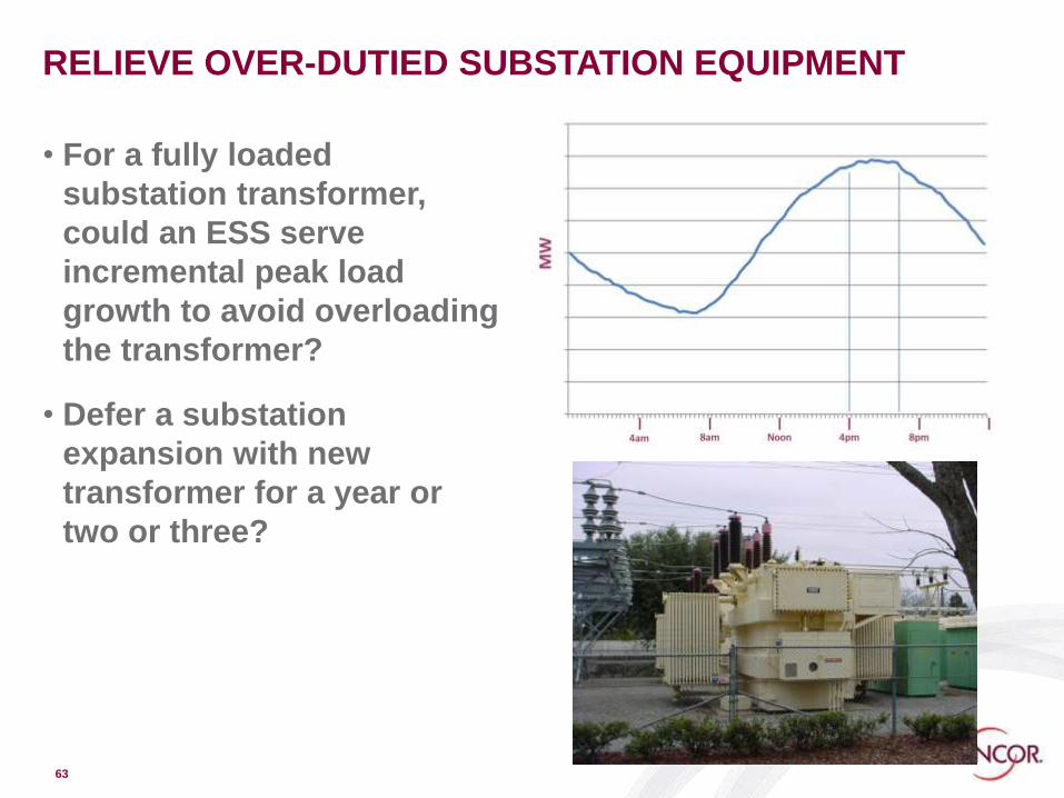
RELIEVE OVER-DUTIED SUBSTATION EQUIPMENT
• For a fully loaded
substation transformer,
could an ESS serve
incremental peak load
growth to avoid overloading
the transformer?
• Defer a substation
expansion with new
transformer for a year or
two or three?
63

SERVE GROWING LOAD – Substation
• Meet the incremental peak demand on a substation
• When that incremental demand would create total substation
demand that is greater than what the substation equipment can
support
• Case 1 – The peak demand on substation equipment is
growing slowly
• A storage system can meet peak hour needs, and thereby avoid or
defer a major substation upgrade or expansion
• Case 2 – The peak demand on substation equipment is
expected to grow very rapidly
• Storage can be deployed more to defer the traditional upgrade if
more timely or more cost-effective
64
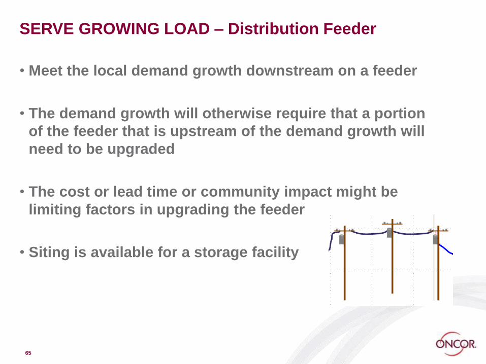
SERVE GROWING LOAD – Distribution Feeder
• Meet the local demand growth downstream on a feeder
• The demand growth will otherwise require that a portion
of the feeder that is upstream of the demand growth will
need to be upgraded
• The cost or lead time or community impact might be
limiting factors in upgrading the feeder
• Siting is available for a storage facility
65

INTEGRATE DER ON A DISTRIBUTION FEEDER
• Maintain required feeder voltage & power factor during
rapid feeder power changes – eg. when clouds come and
go for feeders with high penetration of solar PV systems
• Utilize ESS to complement deployed voltage & power
factor control such as load tap changers (LTC), capacitor
banks, and voltage regulators, all of which are
electromechanical and not designed for frequent
operation
• Utilize energy, power, and reactive capabilities of the ESS
• Frequent use of LTC’s, capacitor banks and voltage regulators will
wear them out, requiring higher maintenance
• Inverter is utilized for feeder voltage & reactive power management
• ESS help balance downstream and upstream power flow
66

STORAGE + DISTRIBUTED ENERGY RESOURCES
67
ESS
SolarGenset
Role of Storage to Integrate DER?
• Mitigate rapid power level change on
feeder voltage (solar smoothing)
• Time-shift energy to more useful
periods
• Keep local energy at local level,
especially if an upgrade of upstream
feeder is needed
• Avoid two-way flow
Solar + ESS

Outline
◼ Why Now?
◼ Energy Storage System (ESS) – Definition
◼ Roles – Bulk Power, Wires, Customer, DER
◼ Utility Distribution Systems
◼ Meet reliability needs
◼ Serve growing demand
◼ Microgrids
◼ Multiple uses of a single ESS
◼ Regulatory & market construct considerations
68Copyright © 2019

LOCAL MICROGRID – FUTURE CONSTRUCT
69
ESS
SolarGenset
ESS on Feeder with DER
• Feeder segment with storage
• Grid-connected and islanded
operations
• Grid-connected: Limit abrupt
changes of power level on
feeder/support voltage stability
• Islanded: ESS as grid-forming
element / Controller dispatches
supply and ESS to balance with load
during island
Solar + ESS
Reliability → Resilience
• Utilize ESS to support feeder segment
in an outage
• Distributed energy resources (DER)
extend the electrical island operation
• Local controller to maintain frequency
& voltage, resynchronize to the grid
• Controller dispatches supply and ESS
to balance with load
• Reliability → Resilience if designed
for robust events

70
Outline
◼ Why Now?
◼ Energy Storage System (ESS) – Definition
◼ Roles – Bulk Power, Wires, Customer, DER
◼ Utility Distribution Systems
◼ Meet reliability needs
◼ Serve growing demand
◼ Microgrids
◼ Multiple uses of a single ESS
◼ Regulatory & market construct considerations
71Copyright © 2019

MORE THAN A SINGLE USE FOR AN ESS
• A common theme in energy storage is to find ways to
maximize the value of the ESS by using it for more than
one purpose
• Define the primary use
• Examine secondary use: 1. contemporaneous with
primary use; 2. at times primary use is not needed
• Avoid degrading capability for the primary application
when designing additional uses
• Rigorous control scheme required
• Avoid reducing life of the ESS unless higher value overall
is achieved
72
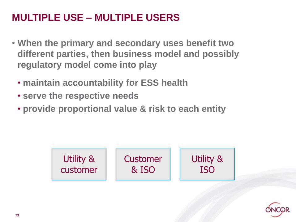
MULTIPLE USE – MULTIPLE USERS
• When the primary and secondary uses benefit two
different parties, then business model and possibly
regulatory model come into play
• maintain accountability for ESS health
• serve the respective needs
• provide proportional value & risk to each entity
73
Utility & customer
Customer & ISO
Utility & ISO
CUSTOMER-SITED ESS SERVING GRID NEEDS
• Several storage business entities are engaging in
customer-sited storage to serve specific customer needs
and to support utility or ISO needs or pursue revenue
opportunities thru ancillary services
• Each ESS performs two or three functions, such as
demand charge management for the customer, and a grid
need for the grid operator
• Aggregation across several customer-sited ESS may be
necessary to reach scale needed for grid support
74

Outline
◼ Why Now?
◼ Energy Storage System (ESS) – Definition
◼ Roles – Bulk Power, Wires, Customer, DER
◼ Utility Distribution Systems
◼ Meet reliability needs
◼ Serve growing demand
◼ Microgrids
◼ Multiple uses of a single ESS
◼ Regulatory & market construct considerations
75Copyright © 2019

CONTACT
Bill Muston
Oncor Electric Delivery Company LLC
214-486-3015
76
How do we reduce the length
& frequency of power
outages?
How do we increase the
efficiency of the grid?
How do we create a more
resilient, secure and even
self-healing power grid?
How do we integrate
increasing amounts of solar
and wind power into the
grid?
How do we support
customers who choose
rooftop solar and electric
vehicles?
How do we achieve all this and still
keep your monthly bill affordable?
References
77Copyright © 2019

TERMS
SAIDI – System Average Interruption Duration Index
• Quantitative measure of the reliability of power service
• Measured in minutes/year
ESS – Energy Storage System
PCS – Power Conversion System
SCADA – Supervisory Control and Data Acquisition
BES – Bulk Electric System – definition http://www.nerc.com/pa/RAPA/BES%20DL/BES%20Definition%20Approv
ed%20by%20FERC%203-20-14.pdf
Battery Terminology Reference –
mit.edu/evt/summary_battery_specifications.pdf
78

TERMS
Smoothing & Firming for Solar & Wind –
The terms ‘smoothing’ and ‘firming’ are used to describe
means to address the variations and intermittency from
individual solar site or wind site installations.
In particular, ‘firming’ refers to bringing predictability and
reliability. As such, it may address pure grid reliability for
grid needs, or may address financial certainty for the
owner/operator of the solar or wind facility, or perhaps
both.
79

TERMS
Interconnection –
An interconnection agreement is required for any party connecting a
generation or storage resource to the grid. During the application
process, engineering studies are conducted to determine what design
requirements are needed to assure safety of people and equipment and
to assure compatibility with grid reliability and operations.
Within ERCOT, for large resources expecting to serve ERCOT energy
and ancillary services markets, the ERCOT process combines all
requests to create a queue that is publicly listed. Being in the queue
does not necessarily mean each project will be completed. Degrees of
financial commitment are required during the process, and those
reaching the highest stage of financial commitment typically will be
completed.
Utilities also have interconnection agreements for customer-site
generation resources, including emergency gensets, solar PV systems,
and energy storage.
80

https://www.smartgrid.gov/files/B5_draft_rep
ort-12-18-2014.pdf
Fault Location, Isolation, and Service Restoration (FLISR)
An essential component for
successful FLISR operations is the
communications network for
remote monitoring and control of
technologies and systems. FLISR
communication networks require
increased resilience because they
must operate under conditions
where the grid itself is damaged or
not functioning properly. The two-
way communications network must
have sufficient coverage and
capacity to interface and
interoperate with a wide variety of
technologies and systems,
including various field devices and
DMS, OMS, and SCADA systems.
From U.S. Department of Energy report
Fault Location, Isolation, and Service
Restoration Technologies Reduce Outage
Impact and Duration

References – Page 1
EPRI
Energy Storage Technology and Cost Assessment: Executive Summary
Technical Report 3002013958, December 2018
https://www.epri.com/#/pages/product/000000003002013958/?lang=en-US
Energy Storage Integration Council (ESIC), hosted by EPRI, focused on utility distribution
applications https://www.epri.com/#/pages/sa/epri-energy-storage-integration-council-
esic?lang=en-US
MESA – Modular Energy Storage Association – ‘Open Standards for Energy Storage’ –
http://mesastandards.org/
Sandia National Laboratory – Energy Storage Systems Program – facilitates and publishes a
variety of DOE-sponsored studies and reports related to the application of ESS –
https://www.sandia.gov/ess-ssl/
Sandia Energy Storage Safety Collaborative
https://www.sandia.gov/energystoragesafety-ssl/
82

References – Page 2
Fault Location, Isolation, and Service Restoration (FLISR)
https://www.smartgrid.gov/files/B5_draft_report-12-18-2014.pdf
Northern Power Low Carbon Network Fund Youtube Video
http://www.youtube.com/watch?v=KUGpUaA4D5k&index=1&list=UUx_iDK8VCyKqYmAkORA
hNzw
AEP Filing with PUCT on storage for specific reliability and asset deferral projects
• PUCT 46368 – find on http://interchange.puc.texas.gov/ , and open or download Item 2 –
APPLICATION OF AEP TEXAS NORTH COMPANY FOR REGULATORY APPROVALS
RELATED TO THE INSTALLATION OF UTILITY-SCALE BATTERY FACILITIES
• Despite being a legal document with a regulatory agency, it contains very readable descriptions of the
proposed projects, one being reliability for a rural community on the end of a radial line, and the other
being an alternative to traditional methods to serve growing load in a community at the end of a radial
line
83

References – Page 3
Austin Energy’s DOE SHINES Project
https://austinenergy.com/ae/green-power/austin-shines/austin-shines-innovations-energy-
storage
Arizona Public Service ‘Solar Partners’ Energy Storage
http://www.tdworld.com/energy-storage/aps-aes-bring-energy-storage-arizona-customers
San Diego Gas & Electric Unveils Worlds Largest Lithium-Ion Energy Storage
http://www.tdworld.com/renewables/sdge-unveils-worlds-largest-lithium-ion-battery-energy-
storage-facility?NL=TDW-01&Issue=TDW-01_20170301_TDW-
01_946&sfvc4enews=42&cl=article_4_b&utm_rid=CPG04000000116581&utm_campaign=1276
3&utm_medium=email&elq2=55c63a250535471ea5d6c1a4195b2961
Oncor Confidential - For Internal Use Only84

References – Page 4
Brattle Report Examining Dual Technical Uses of Battery wherein the Users Are Utility and
Market Participants, Respectively
• Brattle Press Release – a good summary of the report
• http://www.brattle.com/news-and-knowledge/news/749
•
• Link to Full-Length Technical Report Released in 2015
• http://www.brattle.com/system/publications/pdfs/000/005/126/original/The_Value_of_Distributed_Electricity_Storage_in_Texas_-
_Proposed_Policy_for_Enabling_Grid-Integrated_Storage_Investments_Full_Technical_Report.pdf?1426377384
• Presentation
• http://www.brattle.com/system/publications/pdfs/000/005/119/original/The_Value_of_Distributed_Electrical_Energy
_Storage_in_Texas.pdf?1423513210
85
ENERGY STORAGE USE CASES
86
• Publicly available use cases are generally high-level descriptions
and ESS performance expectations
• The DOE/EPRI/NRECA “Handbook” from 2013 provides many use
cases. A more recent version has been rumored, but is not yet
available. • https://www.sandia.gov/ess-ssl/lab_pubs/doeepri-electricity-storage-handbook/
• The use cases within the Lazard Levelized Cost of Storage v2.0 also
provide a good summary introduction• https://www.lazard.com/perspective/levelized-cost-of-storage-analysis-
20/?utm_content=buffer7978d&utm_medium=social&utm_source=twitter.com&u
tm_campaign=buffer

87

88

ONCOR STORAGE PROJECTS
NSRI – Neighborhood Storage
Reliability Initiative
Rural Feeder Reliability – Study –
Can a battery located on long rural
feeder support customers when
the upstream portion of a feeder is
out?
Microgrid at Oncor operational
facility
89

Homework Exercises:Thursday, March 28.
1. ESS specifications for distribution feeders depend on the applications they must serve (kVA capacity of inverter and kWh capacity of battery)
◼ Peak Shaving (kVA and kWh requirement)
◼ Islanding (kVA and kWh requirement)
◼ System Protection (kVA requirement)

Background
◼ Today, the maximum kVA of load on a feeder is 2750 kVA without overloading the substation transformer
◼ The peak load on that feeder is projected to grow in a year from 2750 kVA to 2951 kVA
◼ On peak load day the load is expected to go above 2750 kVA limit for 2.5 hours, as shown in the graph
◼ The first parts of the question will be to specify an ESS to support this increased peak load in lieu of a substation upgrade that would require a new substation transformer and bus
◼ Assumption: assume the area of the peak load curve above the level of 2750 kVA is an isosceles triangle to simplify the calculation

Background
◼ The next parts of the question will be, for the same feeder, specify an ESS to support the downstream half of the feeder with the ESS during an upstream outage
◼ The outage is over the same future peak hours load curve as the prior problem
◼ The last part of the question will be to size the ESS to support fault current for fuses serving a 3-phase load for a fault during islanded operation:◼ A fault is assumed to occur on a feeder lateral during
islanded operation, requiring the inverter to provide fault current through the fuse on the lateral.

Additional assumptions
◼ Assume the ESS is a perfectly efficient unit, with no losses through the inverter and no losses in the battery through charging or discharging◼ A kWh ac is the same as a kWh dc
◼ Assume the feeder is operating at unity (1.0) power factor
◼ Assume the load shape during those peak hours (for the portion above 2750 kVA) is an isoceles triangle with the base being the segment along 2750 kVA
◼ Assume the ESS performance is not affected by ambient temperature
◼ Assume the feeder load curve is precisely halved for the A.2 problem

Questions
1. Refer to Feeder Load Curve
A. To serve the growing load, what kVA capacity ESS can prevent feeder overload?
B. Approximately how many kWh of energy storage would be needed to support the peaking period?
C. To support the downstream half of the feeder with ESS during an outage on the other half of the feeder, approximately what kVA capacity would the ESS need to be able to island half of the feeder load during peaking time? Assume the load shape curve is precisely half for the half of the feeder to be supported by the ESS during an outage
D. How many kWh are needed? Assume the shape is a rectangle on the bottom and a triangle on the top

Questions
1.
Refer to Fuse Curve
E. A 1000 kVA 3-phase load is attached to the half of the feeder on island protected by 65 A primary fuses (12.5 kV phase-to-phase). Assume the ESS inverter can provide 150% of its continuous kVA rating for 10 seconds. Approximately what continuous kVA capacity would the ESS need to be able to operate all three fuses in under 5 seconds?

Feeder Load – 1 day
Peaking Time

5 s

Problem Statement 2Customer-Sited Storage
◼ The commercial customer decides to install an ESS to limit its peak load, in order to reduce demand charges
◼ The demand charge is based on the peak load over a 15-minute interval each month, and is reflected in a monthly charge on the utility bill
A. How large should the ESS be to reduce the demand incurred in the three hourly blocks of time of 14:00 thru 16:00 blocks to the level shown for the 08:00 thru 13:00 hour blocks?
B. What does the discharge and recharge profile look like, if a slow recharge is conducted over hours not being discharged? What is the customer’s new maximum demand on the grid?
C. What should the recharge profile be to avoid increasing total demand above the amount shown for the 08:00 thru 13:00 hour blocks? What would the customer’s new maximum demand be in this case?
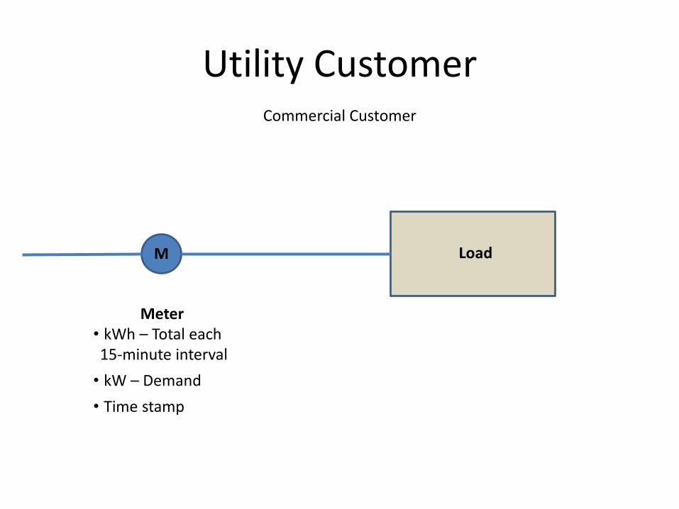
Utility Customer
M
Meter• kWh – Total each 15-minute interval
• kW – Demand
• Time stamp
Load
Commercial Customer

Utility Customer Adds Storage
Load
ESSM
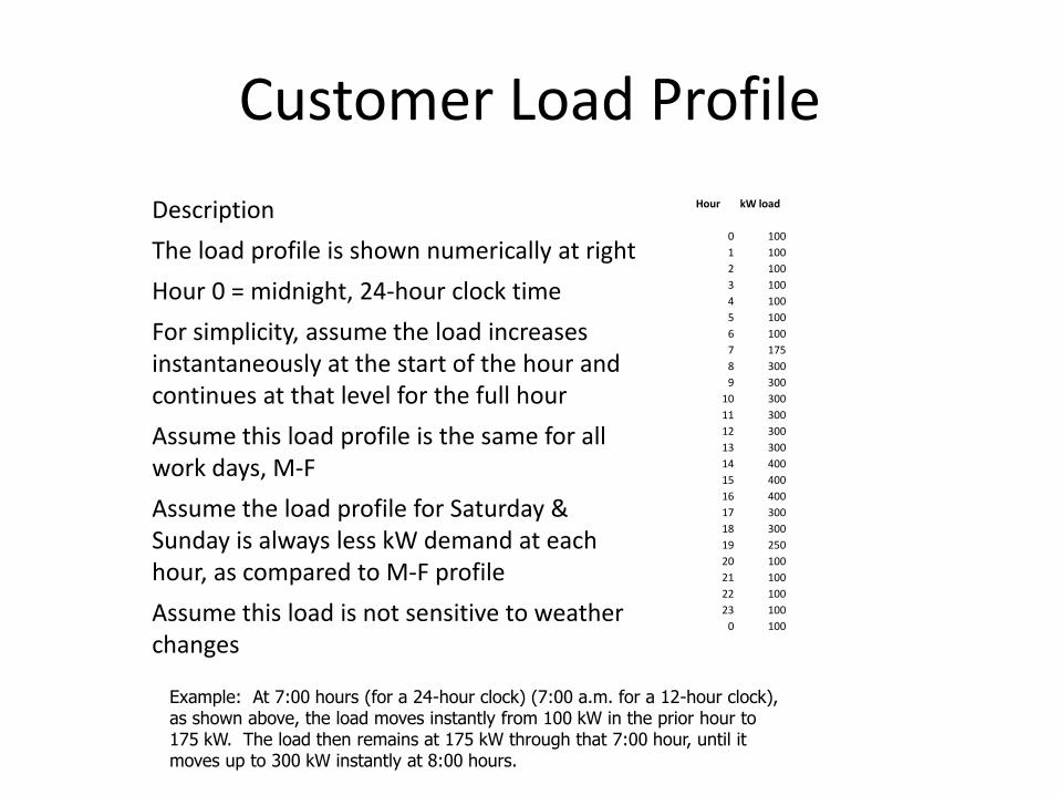
Customer Load Profile
Hour kW load
0 100
1 100
2 100
3 100
4 100
5 100
6 100
7 175
8 300
9 300
10 300
11 300
12 300
13 300
14 400
15 400
16 400
17 300
18 300
19 250
20 100
21 100
22 100
23 100
0 100
Description
The load profile is shown numerically at right
Hour 0 = midnight, 24-hour clock time
For simplicity, assume the load increases instantaneously at the start of the hour and continues at that level for the full hour
Assume this load profile is the same for all work days, M-F
Assume the load profile for Saturday & Sunday is always less kW demand at each hour, as compared to M-F profile
Assume this load is not sensitive to weather changes
Example: At 7:00 hours (for a 24-hour clock) (7:00 a.m. for a 12-hour clock), as shown above, the load moves instantly from 100 kW in the prior hour to 175 kW. The load then remains at 175 kW through that 7:00 hour, until it moves up to 300 kW instantly at 8:00 hours.

Demand Charge Mgt
◼ Differential demand at peak = peak hours kW less mid-level demand = ESS kW capability
◼ Peak duration is over the peak hours shown above
◼ Energy in ESS needed = ESS kW x hours of discharge
◼ Recharge Rate – Case #1◼ Over 24 hours less the hours being discharged
◼ Recharge Rate – Case #2◼ 24 hours less all hours 300 kW or higher
Recharge Rate = kW for the period of recharging the battery

Problem Statement 3 –AEP Projects Proposed
◼ Read the AEP filing at the PUCT, which is Item 2, as noted in the References
◼ Read the summary and the section of testimony by the Director of Distribution Engineering
Copyright © 2019 103

AEP Projects Proposed
A. For the Woodson project, how many outages has the community experienced in the last 5 years?
B. Of those, how many were of a duration of 2 hours or less?
C. For a battery designed to serve the full community for 2 hours, how many outages would be eliminated?
D. For the outages not eliminated, what is the value to the customers from the battery? (A word answer, not a quantitative answer)
Copyright © 2019 104

AEP Projects Proposed
1. For the Paint Rock proposal, what is the present peak demand on the substation?
2. What is the rated capacity of the substation?
3. What is the battery power capability that is proposed?
4. What is the battery energy capability that is proposed?
Copyright © 2019 105