Embed Size (px)
Citation preview

Innovative and highly efficient temperature control units and systems
enersave series

2
The high-end temperature control units and systems of the enersave series at a glance
The compact protemp series is characterized by its special energy efficiency, high performance and connectivity. The units are available with highly efficient stainless steel centrifugal pumps in a constant or controlled (eco) version. The units stand for particularly high-quality technology, extensive standard equipment, ea-sy use and ease of service. Modern interfaces for connecting machine con-trol systems, MES BDE systems or analysis apps, and an internal bus system for the inte-gration of proflow water distributors fulfil the demands placed on a modern Industry 4.0 solu-tion. A EUROMAP 82.1-capable OPC UA interface,
various manufacturer-specific OPC UA inter-faces, a PROFINET interface and serial RS 485 and TTY interfaces are also available.
In the eco version, the pump energy consumpti-on can be shown on the display, so that the en-ergy consumption can be constantly monitored and optimized.The protemp series is equipped with a micro-processor controller with fast high-performance processors designed specifically for this premi-um series. Uniform operation via the protemp display and control unit with a 4.3“ touch screen with intuitive user interface and user friendly menu navigation.
Subject to technical modification without notice!
protemp temperature controllers for water, using indirect cooling
Type Medium Temperature
range ( °C)
Heating capacity
(kW)
Max.cooling capacity
(kW)
Pump capacity, constant operation max. (l/min / bar)
Pump capacity, control mode x
max. (l/min / bar)
protemp ci 95-s1 water 95 6/9 62 50 / 4,3 55 / 5,0 protemp ci 140-s1 water 140 6/9 95 50 / 4,3 55 / 5,0 protemp ci 95-a1 water 95 9/18 92 70 / 4,7 83 / 6,8 protemp ci 140-a1 water 140 9/18 140 70 / 4,7 83 / 6,8 protemp ci 95-a2 water 95 9/18/27/36 92 105 / 4,9 125 / 7,0 protemp ci 140-a2 water 140 9/18/27/36 140 105 / 4,9 125 / 7,0 protemp ci 95-a3 water 95 30/40/50 308 - 300 / 7,0 protemp ci 140-a3 water 140 30/40/50 472 - 300 / 7,0 protemp ci 95-a4 water 95 30/40/50 308 - 440 / 5,0 protemp ci 140-a4 water 140 30/40/50 472 - 440 / 5,0
protemp temperature controllers for water, using direct cooling
Type Medium Temperature
range ( °C)
Heating capacity
(kW)
Max.cooling capacity
(kW)
Pump capacity, constant operation max. (l/min / bar)
Pump capacity, control mode x
max. (l/min / bar)
protemp cd 95-s2 water 95 9/18 264 140 / 4,2 165 / 5,1 protemp cd 95-a1 water 95 9/18/27/36 397 70 / 4,7 83 / 6,8 protemp cd 95-a2 water 95 9/18/27/36 397 105 / 4,9 125 / 7,0 protemp cd 95-a3 water 95 30/40/50 632 - 300 / 7,0 protemp cd 95-a4 water 95 30/40/50 632 - 440 / 5,0
Subject to technical modification without notice!x = eco version
x = eco version

3Perfect Cooling and Temperature Control www.gwk.com
The high-end temperature control units and systems of the enersave series at a glance
With the outstanding efficiency and performance, as well as numerous features of the standard equipment, such as control cabinet with protection class IP 54, stainless steel pump, dual-frequency 50/60 Hz pump motor, increased flow rate with 3 bar back pressure, increased cooling capacity, flow and return temperature sensor, digital pressure display, electronic flow measurement, acoustic and visual alarm, dirt collector in cooling water inlet and consumer return, separa-te cooling and fill up connection for indirectly cooled advan-ced devices, the digitization concept protemp connect 4.0, and much more makes the enersave series an outstanding product on the market even in the premium segment.
By means of the digitization concept protemp connection 4.0, water distributors of the enersave series can be connected directly to the temperature controller and the process para-meters flow rate and return flow temperature can be displayed and controlled for up to twelve single circuits. Furthermore, via OPC UA or Profinet the process data can be transferred to the machine control systems, MES systems or the gwk tempanalyser App if required.
gwk enersave series-> Leading in energy efficiency due to centrifugal pump technology:
Sample calculation of energy efficiency on the basis of a user benchmark under production conditions:
Pump data competitors peripheral pump 2,8 kW kW pump motor max. flow rate 110 l/min flow rate at 3.8 bar: 50 l/min
Measured energy consumption: 2,2 kW
Pump data gwk "enersave" technology centrifugal pump 2.5 kW pump motor max. flow rate 125 l/min flow rate at 3.8 bar: 50 l/min
Measured energy consumption: 0,3 kW
gwk enersave series -> advanced connectivity due to OPC UA technology:
* with 5,800 operating hours/year and electricity price of € 0.15 / kWh
Savings through "enersave" technology 1.9 kW or 86.4 %, or 1,653 euros / year*
gwk tempanalyser App OPC UA interface
protemp temperature control units
Visualization of the external temperature control circuits on the device display
Data exchange between proflow water distributor and protemp temperature control unit
proflow water distributor with electronic measurement
Energy consumption,
protemp
Energy consumption, competitors

ä
Soll
Ist
P2-Pumpe0
100
200
300
400
0
2
5
7
10
l/min bar
3,5 750,4 kW
65.0 °C
65.0 °C
AA
Example: Display
4
protemp selection series 1 – Designed for smaller consumers
Standard equipment: • Self-optimizing microcontroller with high
control accuracy • Touch screen (4.3") for input, control and
monitoring of process parameters • Measurement, display and monitoring of flow
rate • Intuitive user interface with user-friendly menu
navigation • Measurement, display and monitoring of
supply pressure • Temperature display of return flow • Continuous monitoring of process parameters • Stainless steel centrifugal pump and
stainless steel heat exchanger • Energy consumption display (eco version) • Pump dry run and overheat protection • Speed-controlled centrifugal pump in
efficiency class IE5 (eco version) • Digitization concept protemp connect 4.0 • Automatic water exchange
OPC UA
interface
• Strainer in consumer return and cooling water inlet
• Air separator in the consumer return • Control cabinet protection class IP 54 • Ready for connection with 3 m cable and
CEE socket • Unit front: RAL 7035 Light grey • Hood and side panels: RAL 7016
Anthracite grey • Optional external sensor connection (Pt 100) • Optional interface (RS 485, TTY, Profinet,
OPC UA and proflow) • Optional gwk tempanalyser APP

0 5 10 15 20 25 30 35 40 45 50 55 60 l/min
1
2
3
4
5
6
bar
2 1
Max
imum
Max
imum
5Perfect Cooling and Temperature Control www.gwk.com
Temperature controllers water indirect 95 °C and 140 °C
Tech
nica
l dat
a St
anda
rd s
peci
ficat
ion/
Optio
ns
Model protemp selection, series 1 ci 95-s1 ci 140-s1 ci 95-s1 eco ci 140-s1 eco
Medium water water water water Temperature max. ( °C) 95 140 95 140 Pump capacity max. (l/min / bar) 50 / 4,3 50 / 4,3 55 / 5,0 55 / 5,0 Heating capacity (kW) 6 / 9 6 / 9 6 / 9 6 / 9 Cooling indirect indirect indirect indirect Cooling capacity (kW)1 62 95 62 95 Mould circuit supply and return connections G 3/4” G 3/4” G 3/4” G 3/4” Cooling water supply and return connections G 1/2” G 1/2” G 1/2” G 1/2” Dimensions in mm (L x W x H) 710 x 210 x 615 710 x 210 x 615 710 x 380 x 615 710 x 380 x 615Operating mode of centrifugal pump constant constant controlled / IE5 controlled / IE5Dual frequency 50/60 Hz o o • •Touchscreen with colour display • • • •Robust partly galvanized steel housing, painted in two colours • • • •Automatic filling and top up device • • • •Strainer in cooling water inlet • • • •Strainer in consumer return flow • • • •All contact parts made of non-corrosive materials • • • •Adapted heating system • • • •Acoustic and optical alarm • • • •Mould draining o o o o
Integrated top up-pump - o - o
Return temperature indication • • • •System pressure gauge - • - •
High-performance temperature control unit with increased flow rate and reduced energy consumption
• = Standard / o = Option – = not available
1) at 15 °C cooling water and 90 °C resp. 130 °C circuit water temperature Subject to technical modification without notice!
l1 flow rate at 3.0 bar = 31 l/min
l2 flow rate at 3.0 bar = 35 l/min
----- controlled centrifugal rotary pump (eco version) ----- constant centrifugal rotary pump
Characteristic curve

ä
Soll
Ist
P2-Pumpe0
100
200
300
400
0
2
5
7
10
l/min bar
3,5 750,4 kW
65.0 °C
65.0 °C
AA
Example: Display
6
Standard equipment: • Self-optimizing microcontroller with high
control accuracy • Touch screen (4.3") for input, control and
monitoring of process parameters • Measurement, display and monitoring of flow
rate • Intuitive user interface with user-friendly menu
navigation • Measurement, display and monitoring of
supply pressure • Temperature display of return flow • Continuous monitoring of process parameters • Stainless steel centrifugal pump and
stainless steel heating elements • Energy consumption display (eco version) • Pump dry run and overheat protection • Speed-controlled centrifugal pump in
efficiency class IE5 (eco version) • Digitization concept protemp connect 4.0 • Automatic water exchange
• Control cabinet protection class IP 54 • Strainer in consumer return flow and cooling
water inlet • Ready for connection with 3 m cable and
CEE socket • Unit front: RAL 7035 Light grey • Hood and side panels: RAL 7016
Anthracite grey • Optional external sensor connection (Pt 100) • Optional interface (RS 485, TTY, Profinet,
OPC UA and proflow) • Optional gwk tempanalyser APP
protemp selection series 2 – Designed for medium consumers
OPC UA
interface

0 10 20 30 40 50 60 70 80 90 100 110 120 130 140 150 160 170 l/min
1
2
3
4
5
6
bar
1 2
Max
imum
Max
imum
7Perfect Cooling and Temperature Control www.gwk.com
Temperature controllers water direct 95 °C
Tech
nica
l dat
a St
anda
rd s
peci
ficat
ion/
Optio
ns
Model protemp selection, series 2 cd 95-s2 cd 95-s2 eco
Medium water water Temperature max. ( °C) 95 95 Pump capacity max. (l/min / bar) 140 / 4,2 165 / 5,1 Heating capacity (kW) 9 / 18 9 / 18 Cooling direct direct Cooling capacity (kW)1 264 264 Mould circuit supply and return connections G 1” G 1”Cooling water supply and return connections G 3/4” G 3/4” Dimensions in mm (L x W x H) 1.000 x 280 x 750 1.000 x 280 x 750 Operating mode of centrifugal pump constant / IE3 controlled / IE5 Dual frequency 50/60 Hz - • Touchscreen with colour display • •Robust partly galvanized steel housing, painted in two colours • •Automatic filling and top up device • •Strainer in cooling water inlet • •Strainer in consumer return flow • •All contact parts made of non-corrosive materials • •Adapted heating system • •Acoustic and optical alarm • •Mould draining o o
Return temperature indication • •
• = Standard / o = Option / – = not available
1) bei 15 °C Kühlwassertemperatur und 90 °C Vorlauftemperatur
High-performance temperature control units with increased flow rate and reduced energy consumption
Subject to technical modification without notice!
constant centrifugal rotary pump controlled centrifugal rotary pump (eco version)
flow rate l
1 at 3,0 bar =
100 l/min l
2 at 3,0 bar =
142 l/min
Characteristic curve - - - -----
8
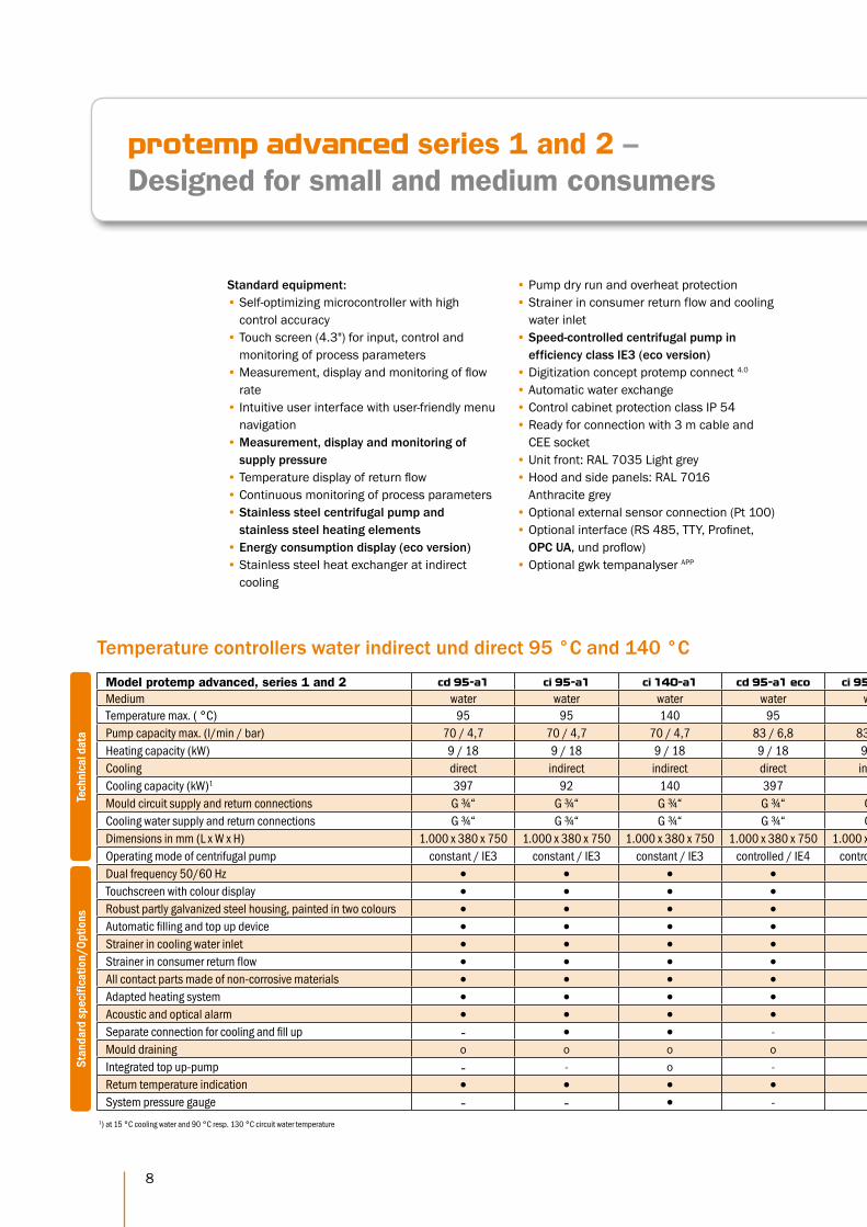
protemp advanced series 1 and 2 – Designed for small and medium consumers
Standard equipment: • Self-optimizing microcontroller with high
control accuracy • Touch screen (4.3") for input, control and
monitoring of process parameters • Measurement, display and monitoring of flow
rate • Intuitive user interface with user-friendly menu
navigation • Measurement, display and monitoring of
supply pressure • Temperature display of return flow • Continuous monitoring of process parameters • Stainless steel centrifugal pump and
stainless steel heating elements • Energy consumption display (eco version) • Stainless steel heat exchanger at indirect
cooling
Temperature controllers water indirect und direct 95 °C and 140 °C
Tech
nica
l dat
a St
anda
rd s
peci
ficat
ion/
Optio
ns
Model protemp advanced, series 1 and 2 cd 95-a1 ci 95-a1 ci 140-a1 cd 95-a1 eco ci 95-a1 eco ci 140-a1 eco cd 95-a2 ci 95-a2 ci 140-a2 cd 95-a2 eco ci 95-a2 eco ci 140-a2 eco
Medium water water water water water water water water water water water water Temperature max. ( °C) 95 95 140 95 95 140 95 95 140 95 95 140 Pump capacity max. (l/min / bar) 70 / 4,7 70 / 4,7 70 / 4,7 83 / 6,8 83 / 6,8 83 / 6,8 105 / 4,9 105 / 4,9 105 / 4,9 125 / 7,0 125 / 7,0 125 / 7,0 Heating capacity (kW) 9 / 18 9 / 18 9 / 18 9 / 18 9 / 18 9 / 18 9 / 18 / 27 / 36 9 / 18 / 27 / 36 9 / 18 / 27 / 36 9 / 18 / 27 / 36 9 / 18 / 27 / 36 9 / 18 / 27 / 36 Cooling direct indirect indirect direct indirect indirect direct indirect indirect direct indirect indirect Cooling capacity (kW)1 397 92 140 397 92 140 397 92 140 397 92 140 Mould circuit supply and return connections G ¾“ G ¾“ G ¾“ G ¾“ G ¾“ G ¾“ G 1“ G 1“ G 1“ G 1“ G 1“ G 1“Cooling water supply and return connections G ¾“ G ¾“ G ¾“ G ¾“ G ¾“ G ¾“ G ¾“ G ¾“ G ¾“ G ¾“ G ¾“ G ¾“ Dimensions in mm (L x W x H) 1.000 x 380 x 750 1.000 x 380 x 750 1.000 x 380 x 750 1.000 x 380 x 750 1.000 x 380 x 750 1.000 x 380 x 750 1.000 x 380 x 750 1.000 x 380 x 750 1.000 x 380 x 750 1.000 x 380 x 750 1.000 x 380 x 750 1.000 x 380 x 750 Operating mode of centrifugal pump constant / IE3 constant / IE3 constant / IE3 controlled / IE4 controlled / IE3 controlled / IE3 constant / IE3 constant / IE3 constant / IE3 controlled / IE3 controlled / IE3 controlled / IE3 Dual frequency 50/60 Hz • • • • • • • • • • • •Touchscreen with colour display • • • • • • • • • • • •Robust partly galvanized steel housing, painted in two colours • • • • • • • • • • • •Automatic filling and top up device • • • • • • • • • • • •Strainer in cooling water inlet • • • • • • • • • • • •Strainer in consumer return flow • • • • • • • • • • • •All contact parts made of non-corrosive materials • • • • • • • • • • • •Adapted heating system • • • • • • • • • • • •Acoustic and optical alarm • • • • • • • • • • • •Separate connection for cooling and fill up - • • - • • - • • - • •Mould draining o o o o o o o o o o o o
Integrated top up-pump - - o - - o - - o - - o
Return temperature indication • • • • • • • • • • • • System pressure gauge - - • - - • - - • - - •
• Pump dry run and overheat protection • Strainer in consumer return flow and cooling
water inlet • Speed-controlled centrifugal pump in
efficiency class IE3 (eco version) • Digitization concept protemp connect 4.0
• Automatic water exchange • Control cabinet protection class IP 54 • Ready for connection with 3 m cable and
CEE socket • Unit front: RAL 7035 Light grey • Hood and side panels: RAL 7016
Anthracite grey • Optional external sensor connection (Pt 100) • Optional interface (RS 485, TTY, Profinet,
OPC UA, und proflow) • Optional gwk tempanalyser APP
1) at 15 °C cooling water and 90 °C resp. 130 °C circuit water temperature

0 10 20 30 40 50 60 70 80 90 100 110 120 130 l/min
1
2
3
4
5
6
7
8
bar
1 2 3 4
Max
imum
Max
imum
Max
imum
Max
imum
9Perfect Cooling and Temperature Control www.gwk.com
Model protemp advanced, series 1 and 2 cd 95-a1 ci 95-a1 ci 140-a1 cd 95-a1 eco ci 95-a1 eco ci 140-a1 eco cd 95-a2 ci 95-a2 ci 140-a2 cd 95-a2 eco ci 95-a2 eco ci 140-a2 eco
Medium water water water water water water water water water water water water Temperature max. ( °C) 95 95 140 95 95 140 95 95 140 95 95 140 Pump capacity max. (l/min / bar) 70 / 4,7 70 / 4,7 70 / 4,7 83 / 6,8 83 / 6,8 83 / 6,8 105 / 4,9 105 / 4,9 105 / 4,9 125 / 7,0 125 / 7,0 125 / 7,0 Heating capacity (kW) 9 / 18 9 / 18 9 / 18 9 / 18 9 / 18 9 / 18 9 / 18 / 27 / 36 9 / 18 / 27 / 36 9 / 18 / 27 / 36 9 / 18 / 27 / 36 9 / 18 / 27 / 36 9 / 18 / 27 / 36 Cooling direct indirect indirect direct indirect indirect direct indirect indirect direct indirect indirect Cooling capacity (kW)1 397 92 140 397 92 140 397 92 140 397 92 140 Mould circuit supply and return connections G ¾“ G ¾“ G ¾“ G ¾“ G ¾“ G ¾“ G 1“ G 1“ G 1“ G 1“ G 1“ G 1“Cooling water supply and return connections G ¾“ G ¾“ G ¾“ G ¾“ G ¾“ G ¾“ G ¾“ G ¾“ G ¾“ G ¾“ G ¾“ G ¾“ Dimensions in mm (L x W x H) 1.000 x 380 x 750 1.000 x 380 x 750 1.000 x 380 x 750 1.000 x 380 x 750 1.000 x 380 x 750 1.000 x 380 x 750 1.000 x 380 x 750 1.000 x 380 x 750 1.000 x 380 x 750 1.000 x 380 x 750 1.000 x 380 x 750 1.000 x 380 x 750 Operating mode of centrifugal pump constant / IE3 constant / IE3 constant / IE3 controlled / IE4 controlled / IE3 controlled / IE3 constant / IE3 constant / IE3 constant / IE3 controlled / IE3 controlled / IE3 controlled / IE3 Dual frequency 50/60 Hz • • • • • • • • • • • •Touchscreen with colour display • • • • • • • • • • • •Robust partly galvanized steel housing, painted in two colours • • • • • • • • • • • •Automatic filling and top up device • • • • • • • • • • • •Strainer in cooling water inlet • • • • • • • • • • • •Strainer in consumer return flow • • • • • • • • • • • •All contact parts made of non-corrosive materials • • • • • • • • • • • •Adapted heating system • • • • • • • • • • • •Acoustic and optical alarm • • • • • • • • • • • •Separate connection for cooling and fill up - • • - • • - • • - • •Mould draining o o o o o o o o o o o o
Integrated top up-pump - - o - - o - - o - - o
Return temperature indication • • • • • • • • • • • • System pressure gauge - - • - - • - - • - - •
• = Standard / o = Option / – = not available
High-performance temperature control units with increased flow rate and reduced energy consumption
Subject to technical modification without notice!
flow rate
l1 = at 4,0 bar = 40 l/min
l2
= at 4,0 bar = 75 l/min
l3 = at 4,0 bar = 85 l/min
l4 = at 4,0 bar = 120 l/min
----- ----- - - - - - -
controlled centrifugal rotary pump series 1 (eco version) constant centrifugal rotary pump series 1 controlled centrifugal rotary pump series 2 (eco version) constant centrifugal rotary pump series 2
Characteristic curve

10
protemp advanced 3 and 4 – Designed for medium and large consumers
Standard equipment: • Self-optimizing microcontroller with high
control accuracy • Touch screen (4.3") for input, control and
monitoring of process parameters • Measurement, display and monitoring of flow
rate • Intuitive user interface with user-friendly menu
navigation • Measurement, display and monitoring of
supply pressure • Temperature display of return flow • Continuous monitoring of process parameters • Stainless steel centrifugal pump and
stainless steel heating elements • Energy consumption display • Stainless steel heat exchanger with indirect
cooling • Pump dry run and overheat protection • Speed-controlled centrifugal pump in
efficiency class IE3 • Digitization concept protempconnect 4.0
• Automatic water exchange
Temperature controllers water direct and indirect 95 °C and 140 °C
Tech
nica
l dat
a Au
ssta
ttung
/Opt
ione
n
Model protemp advanced, series 3 and 4 cd 95-a3 eco ci 95-a3 eco ci 140-a3 eco cd 95-a4 eco ci 95-a4 eco ci 140-a4 eco
Medium water water water water water water Temperature max. ( °C) 95 95 140 95 95 140 Pump capacity max. (l/min / bar) 300 / 7,0 300 / 7,0 300 / 7,0 440 / 5,0 440 / 5,0 440 / 5,0 Heating capacity (kW) 20 / 30 / 40 / 50 20 / 30 / 40 / 50 20 / 30 / 40 / 50 20 / 30 / 40 / 50 20 / 30 / 40 / 50 20 / 30 / 40 / 50 Cooling direct indirect indirect direct indirect indirect Cooling capacity (kW)1 632 308 472 632 308 472Mould circuit supply and return connections G 1 ½“ G 1 ½“ G 1 ½“ G 2“ G 2“ G 2“ Cooling water supply and return connections G 1“ G 1“ G 1“ G 1“ G 1“ G 1“ Dimensions in mm (L x W x H) 1.300 x 520 x 1.050 1.300 x 520 x 1.050 1.300 x 520 x 1.050 1.300 x 520 x 1.050 1.300 x 520 x 1.050 1.300 x 520 x 1.050 Operating mode of centrifugal pump controlled / IE3 controlled / IE3 controlled / IE3 controlled / IE3 controlled / IE3 controlled / IE3 Dual frequency 50/60 Hz • • • • • •Touchscreen with colour display • • • • • •Robust partly galvanized steel housing, painted in two colours • • • • • •Automatic filling and top up device • • • • • •Strainer in cooling water inlet • • • • • •Strainer in consumer return flow • • • • • •All contact parts made of non-corrosive materials • • • • • •Adapted heating system • • • • • •Acoustic and optical alarm • • • • • • Separate connection for cooling and fill up - • • - • •Mould draining o o o o o o
Integrated top up-pump - - o - - o
Return temperature indication • • • • • •System pressure gauge - - • - - •
• Control cabinet protection class IP 54 • Strainer in consumer return flow and cooling
water inlet • Ready for connection with 3 m cable and CEE
socket • Unit front: RAL 7035 Light grey • Hood and side panels: RAL 7016
Anthracite grey • Optional external sensor connection (Pt 100) • Optional interface (RS 485, TTY, Profinet,
OPC UA and proflow) • Optional gwk tempanalyser APP
1) at 15 °C cooling water and 90 °C resp. 130 °C circuit water temperature

0 50 100 150 200 250 300 350 400 450 500 l/min
1
2
3
4
5
6
7
bar
1 2
Max
imum
Max
imum
11Perfect Cooling and Temperature Control www.gwk.com
Temperature controllers water direct and indirect 95 °C and 140 °C
Model protemp advanced, series 3 and 4 cd 95-a3 eco ci 95-a3 eco ci 140-a3 eco cd 95-a4 eco ci 95-a4 eco ci 140-a4 eco
Medium water water water water water water Temperature max. ( °C) 95 95 140 95 95 140 Pump capacity max. (l/min / bar) 300 / 7,0 300 / 7,0 300 / 7,0 440 / 5,0 440 / 5,0 440 / 5,0 Heating capacity (kW) 20 / 30 / 40 / 50 20 / 30 / 40 / 50 20 / 30 / 40 / 50 20 / 30 / 40 / 50 20 / 30 / 40 / 50 20 / 30 / 40 / 50 Cooling direct indirect indirect direct indirect indirect Cooling capacity (kW)1 632 308 472 632 308 472Mould circuit supply and return connections G 1 ½“ G 1 ½“ G 1 ½“ G 2“ G 2“ G 2“ Cooling water supply and return connections G 1“ G 1“ G 1“ G 1“ G 1“ G 1“ Dimensions in mm (L x W x H) 1.300 x 520 x 1.050 1.300 x 520 x 1.050 1.300 x 520 x 1.050 1.300 x 520 x 1.050 1.300 x 520 x 1.050 1.300 x 520 x 1.050 Operating mode of centrifugal pump controlled / IE3 controlled / IE3 controlled / IE3 controlled / IE3 controlled / IE3 controlled / IE3 Dual frequency 50/60 Hz • • • • • •Touchscreen with colour display • • • • • •Robust partly galvanized steel housing, painted in two colours • • • • • •Automatic filling and top up device • • • • • •Strainer in cooling water inlet • • • • • •Strainer in consumer return flow • • • • • •All contact parts made of non-corrosive materials • • • • • •Adapted heating system • • • • • •Acoustic and optical alarm • • • • • • Separate connection for cooling and fill up - • • - • •Mould draining o o o o o o
Integrated top up-pump - - o - - o
Return temperature indication • • • • • •System pressure gauge - - • - - •
• = Standard / o = Option / – = not available
1) at 15 °C cooling water and 90 °C resp. 130 °C circuit water temperature
High-performance temperature control units with increased flow rate and reduced energy consumption
Subject to technical modification without notice!
flow rate
l1 = at 4,0 bar = 280 l/min
l2 = at 4,0 bar = 400 l/min
controlled centrifugal rotary pump series 3 controlled centrifugal rotary pump series 4
Characteristic curve ----- - - -

12
protemp flow ultrasonic – Mobile multi-circuit temperature control with contactless flow measurement
The mobile multi-circuit temperature control protemp flow offers the maximum energy efficiency, performance and monitoring. This device concept combines the advantages of the protemp advanced, series 2, and of the enersave proflow ultrasonic in one device. The multiple distribution system is designed for individual adjustment and monitoring of the flow and the return flow temperature of parallel load circuits. The system thus ensures the hydraulic compen-sation in temperature control circuits with diffe-rent pressure losses and allows a cost-efficient and reliable distribution of the flow rate supplied by the device.
The flow measurement of the individual consu-mer circuits is contactless and takes place by means of ultrasonic sensors. The flow rates and the return flow temperature
are displayed for each circuit on the display of the temperature control unit. In addition to the indication in the device display, the flow rate is displayed on the sensor and the status is signalled with a large red/green LED. Process monitoring takes place by setting minimum flow rate limits. Once the limit value falls below the threshold, an alarm function is triggered and displayed in the device as well as on the sensor.
The process values can be transferred to higher-level control systems via the optional OPC UA temperature control unit interface and visualized there. The gwk tempanalyser APP , offers a process data analysis and visualization solution which can be used on Windows, Adroid or iOS operating systems.
Exemplary display on the gwk tempanalyser APP
In addition to the display in the temperature control unit: Display of the flow rate and the status on the sensor

13Perfect Cooling and Temperature Control www.gwk.com
protemp flow ultrasonic – Mobile multi-circuit temperature control with contactless flow measurement
Tech
nica
l dat
a St
anda
rd s
peci
ficat
ion/
Optio
ns
Model protemp flow ultrasonic cd 95-a2 pf eco cd 95-a2 pf eco
Number of monitoring circuits 4 6 Medium water water Temperature max. ( °C) 95 95 Pump capacity max. (l/min / bar) 125 / 7,0 125 / 7,0 Heating capacity (kW) 9 / 18 / 27 / 36 9 / 18 / 27 / 36 Cooling direct direct Cooling capacity (kW)1 397 397 Mould circuit supply and return connections (distributor mode) G ½“ G ½“ Mould circuit supply and return connections (single operation) G 1“ G 1“ Cooling water supply and return connections G ¾“ G ¾“ Dimensions in mm (L x W x H) 1.200 x 380 x 1.100 1.200 x 380 x 1.100 Operating mode of centrifugal pump controlled / IE3 controlled / IE3 Dual frequency 50/60 Hz • •Touchscreen with colour display • •Robust partly galvanized steel housing, painted in two colours • •Automatic filling and top up device • •Strainer in cooling water inlet • •Strainer in consumer return flow • •All contact parts made of non-corrosive materials • •Adapted heating system • •Acoustic and optical alarm • •Mould draining o o
Return temperature indication • •
Standard equipment: • Multi-distributor for 4 or 6 circuits installed on
the device • Display, communication, operation via the
touch screen of the temperature control unit • Continuous, maintenance-free and dirt-
insensitive flow measurement (no media contact) per distributor circuit
• Common temperature measurement and display in the flow
• Separate temperature measurement in the return line per distribution circuit
• Display and monitoring of the flow per distribution circuit
• Limit setting for flow rate per distribution circuit
• Shut-off ball valve per distributor circuit in the feed and return line
• Bypass line to bypass the distributor and use the temperature control unit as a single circuit unit
• Optional interface (RS 485, TTY, Profinet, OPC UA and proflow)
1) at 15 °C cooling water and 90 °C circuit water temperature
• = Standard / o = Option / – = not availableTemperature controllers water direct 95 °C
Subject to technical modification without notice!

14
proflow mechanical – maximum process control
Maximum process data acquisition and process control and almost maintenance-free
To meet user’s desire for easy maintenance and low sensitivity to slightly soiled water, the proflow mechanical, as a replacement for the previous and commonly used standard measuring device with impeller, nozzle or Vortex, allows the mechanical measurement based on the differential pressure principle, without rotating parts. The sensors can be visualized via a pulsetemp® or protemp control depending on version, or be connected to a PLC. The proflow ultrasonic allows a completely contactless flow measurement based on the ultrasonic principle.
6-way distributor with flow and temperature measurement
For connecting to an enersave visualization Temperature range -10 to 100 °C Measuring range: 1.0 bis 25 l/min
For connecting to an enersave visualization Temperature range 10 to 180 °C Measuring range: 0.3 bis 50 l/min
Flow measurement available in two versions:
• Robust flow measurement in the consumer return
• PT 1.000 temperature measurement in the consumer return
• No infeed/outfeed sections required • 4 or 6 x temperature control
connection 3/4“ IG • 1 x main connection 1“ IG • Available in three temperature versions:
Operating temperatures up to 100 °C, up to 160 °C and up to 180 °C
• Max. flow rate per circuit: 25 l/min or 50 l/min • Max. temperatures: 100 °C / 160 °C / 180 °C

15Perfect Cooling and Temperature Control www.gwk.com
proflow mechanical – maximum process control
Model proflow mechanical Temperature range max. 100 °C / 160 °C / 180 °C Heat transfer medium water Operating modes Temperature and flow monitoring Number of circuits 4 or 6 Temperature measurement PT 1000 Flow measurement per temperature control circuit
mechanical; measuring range 1 - 25 l/min (100 °C); 0.3 - 50 l/min (160/180 °C)
Mechanical connection Main connection1 x flow R1" IG; 1 return R1" IG Distribution module Temperature control circuits: 4 or 6 x R 1/2" IG Coating Stainless steel
Subject to technical modification without notice!
Exemplary display on the gwk tempanalyser APP
gwk tempanalyser App OPC UA interface
protemp temperature control units
Visualization of the external temperature control circuits on the device display
Data exchang between proflow water distributor and protemp temperature control unit
proflow water distributor with electronic measurement

16
proflow ultrasonic – maximum process control
Maximum process data acquisition and process control and maintenance-free
To meet user’s desire for easy maintenance and low sensitivity to slightly soiled water, the proflow ultrasonic, in addition to the previous and commonly used standard measuring device with impeller or turbines or vortex, allows now the contactless ultrasonic measurement using the dTOF technology. The sensors can be visualized via a PulseTemp® or ProTemp or PLC control depending on version, or be used as a pure local display.
The mechanical flow measurement based on the differential pressure principle with the proflow mechanical can be used as an alternative.
• Simple integration in machines and systems possible
• 4 or 6 x consumer circuit connection (flow/return) 1/2“ IG
• Contactless flow measurement • Numerous possibilities of data communication • With dTOF technology and DDS function • With LED local display of flow values • Temperature measurement PT 1.000 • Large RED/GREEN status LED • 1 x main connection 1“ IG • Flow rate per circuit: 1 ... 30 l/min
(no “overload-risk”, a permanent-> 60 l/min possible)
• Operating temperature: 0 ... 120 °C
4-fold distributor with contact-free flow rate measuring

17Perfect Cooling and Temperature Control www.gwk.com
proflow ultrasonic – maximum process control
Subject to technical modification without notice!
The protemp connect 4.0 digitization concept offers many communication options:
Additional control integration via OPC UA possible
Visualization of the external temperature control circuits on
the device display
Controlled connection to the protemp via internal gwk bus
Supply of up to 12 circuits with 10 l/min @ 3.0 bar possible
Input 3 x 380 - 480 V
50/60 Hz possible
enersave series
IMM control
gwk Tempanalyser APP
"Contactless flow measurement with ultrasound"
I/O Box I/O Box
1" 1"
Model proflow ultrasonic Temperature range max. 120 °C Heat transfer medium water Operating modes Temperature / flow display Operating modes 4/6 Temperature measurement PT 1000 Flow measurement per temperature control circuit
contactless; Measuring range 1-30 l/min
Mechanical connection Main connection 1 x flow R1" IG; 1 return R1" IG Distribution module Temperature control circuits: 4 or 6 x R 1/2" IG Coating RAL 7035

18
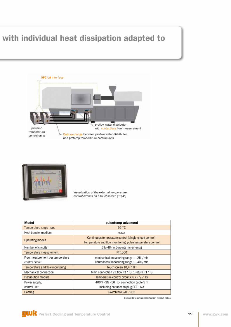
pulsetemp advanced – temperature control with individual heat dissipation adapted to moulded parts
Temperature control with individual heat dissipa- tion/supply and contactless flow measurement adapted to moulded parts
Due to the innovative regulation of the pulsetemp®, heat supplied to the mould zones can be regulated. From two basic temperature levels, the pulsetemp® automatically provides the required and each case different mould inlet temperatures. The mould outlet temperature is used as a control value. The pulsetemp® system allows, due to its modular design, almost any combination. A unique feature is the multi-func-tionality of the system. Depending on requirements, the pulsetemp® can be used both in continuous control mode and in discontinuous pulse mode. In the pulsetemp® ultrasonic, the flow measure-ment is contactless.
• Individual regulation of the heat balance in individual circles
• Regulation depending on the mould outlet temperature
• Temperature as target value specification • Automatic regulation to different mould inlet
temperatures (combination of two temperature levels)
• Also available with contactless flow measurement
• Main connection: 3 x 1“ IG • Consumer connection: 1/2“ IG • Number of circuits per distributor: 6 • Max. number of circuits, total: 48
No rotating parts in the medium. The flow measurement takes place through a mechanical movement. Contaminated tempering medium is therefore from now on not a big problem.
No connection to the medium. The flow measurement takes place without contact to the temperature control medium. Contaminated tempering medium is therefore from now on no longer a problem.
19Perfect Cooling and Temperature Control www.gwk.com
pulsetemp advanced – temperature control with individual heat dissipation adapted to moulded parts
Model pulsetemp advanced Temperature range max. 95 °C Heat transfer medium water
Operating modes Continuous temperature control (single-circuit control),
Temperature and flow monitoring, pulse temperature control
Number of circuits 6 to 48 (in 6-points increments) Temperature measurement PT 1000
Flow measurement per temperature control circuit
mechanical; measuring range 1 - 25 l/min contactless; measuring range 1 - 30 l/min
Temperature and flow monitoring Touchscreen 10,4 " TFT Mechanical connection Main connection 2 x flow R1" IG; 1 return R1" IG Distribution module Temperature control circuits: 6 x R 1/2" IG
Power supply, central unit
400 V - 3N - 50 Hz - connection cable 5 m including connection plug CEE 16 A
Coating Switch box RAL 7035
Subject to technical modification without notice!
OPC UA interface
protemp temperature control units Data exchange between proflow water distributor
and protemp temperature control units
proflow water distributor with contactless flow measurement
Visualization of the external temperature control circuits on a touchscreen (10,4'')

gwk integrat 4D Optimal product quality through homogeneous temperature distribution by temperarture control with close-to-cavity mould inserts.
gwk container-plants Highest flexibility and lowest expenses for planning, in stallation and relocation of a centralised cooling plant.
gwk weco Controllable production in variable climatic conditions and high flexibility with compact, energy-saving water chillers using environmentally friendly refrigerant.
gwk moldclean Increased productivity through effective, automatically con-trolled cleaning of heat ex-change surfaces in cooling and temperature controlled circuits.
gwk hermeticool hybrid Innovative cooling system to decrease the running and main-tenance cost in comparison to conventional cooling systems.
gwk skl/skw Reliable and economic supply of cooling water in the low temperature range, even under the toughest ambient conditions.
gwk teco wi/wd Effective temperature control of applications with high material throughput. Also ideal for pre-heating of large injection moulds.
gwk Gesellschaft Wärme Kältetechnik mbH Scherl 10 · D-58540 Meinerzhagen Tel. +49 2354 7060-0 · Fax +49 2354 7060-150 [email protected] · www.gwk.com
Member of the technotrans group
gwk teco c The compact series with excellent price-performance ratio for the demanding plastics processor.
integrat 40/80/direct Increase of productivity by means of specific and segmented mould temperature control.
Increased productivityIn many areas of the industry, cooling and temperature control provides a great potential for increasing productivity and thus for lowering costs.
• Reduction of cooling time, therefore savings in required machine hours
• Improvement of product quality
• Increasing availability of production plants • Decreasing running cost • Reduction of maintenance cost
Many factors serve to improve productivity:
Production costs
Cost reduction
Perfect Cooling and Temperature Control
gwk service Decreasing the maintenance cost and protection of company owned resources through pro-fessional execution of installa-tion and maintenance works incl. cooling water treatment.
enrs
ave_
GB
_09
/ 2
018
· S
ubje
ct to
tech
nica
l mod
ifica
tion
with
out n
otic
e!