Embed Size (px)
Citation preview
3001850 05.16 Installation & Operating Manual
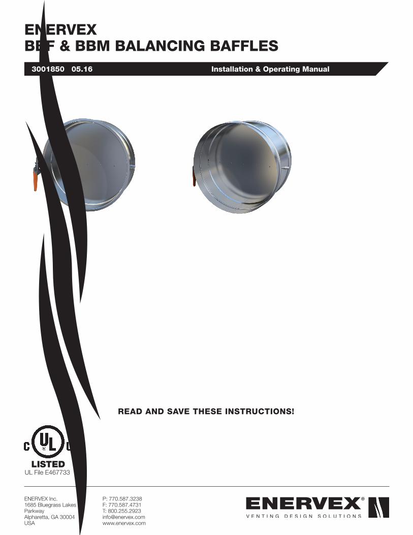
ENERVEXBBF & BBM BALANCING BAFFLES
ENERVEX Inc.1685 Bluegrass Lakes Parkway Alpharetta, GA 30004USA
P: 770.587.3238 F: 770.587.4731 T: 800.255.2923 [email protected] www.enervex.com
READ AND SAVE THESE INSTRUCTIONS!
UL File E467733

2
3001850 05.16
This symbol shows that the ENERVEX BBM and BBF Automatic Dampers are listed in the US and certified for Canada under Underwriters Laboratories Inc. file no. E467733.
IMPORTANT: READ THESE INSTRUCTIONS CAREFULLY PRIOR TO INSTALLATION.
• EXAMINE ALL COMPONENTS FOR POSSIBLE SHIPPING DAMAGE PRIOR TO INSTALLATION.
• PROPER JOINT ASSEMBLY IS ESSENTIAL FOR A SAFE INSTALLATION. FOLLOW THESE INSTRUCTIONS EXACTLY AS WRITTEN. CHECK SECURENESS OF JOINTS UPON COMPLETION OF ASSEMBLY.
WARNINGFailure to follow these installation instructions could cause FIRE, CARBON MONOXIDE
POISONING, and/or DEATH. If you are unsure of installation requirements, contact ENERVEX.
UL File E467733
Symbol LegendThe following terms are used throughout this manual to bring attention to the presence of potential hazards, or to important information concerning the product.
DANGER: Indicates an imminent hazardous situation which, if not avoided, will result in death, serious injury or substantial property damage.
WARNING: Indicates an imminent hazardous situation which, if not avoided, may result in personal injury or property damage.
How to use this manual This installation manual does not contain any system design documentation. System design documentation is available from any authorized ENERVEX representative. Accessories, fans, and variable frequency drives are not covered by this manual. Please refer to these component’s individual manuals.
TO REDUCE THE RISK OF FIRE, ELECTRI-CAL SHOCK OR INJURY TO PERSONS, OB-SERVE THE FOLLOWING:
1. Use this unit in the manner intended by the manufacturer. If you have questions, contact the manufacturer at the address or telephone number listed on the front of the manual.
2. Before servicing or cleaning the unit, switch off at service panel and lock service panel to prevent power from being switched on accidentally.
3. Installation work and electrical wiring must be done by a qualified person(s) in accordance with applicable codes and standards.
4. Follow the appliance manufacturer’s guidelines and safety standards such as those published by the National Fire Protection Association (NFPA), and the American Society for Heating, Refrigeration and Air Conditioning Engineers ASHRAE), and the local code authorities.
5. This unit must be grounded.

3
3001850 05.16
Content1. PRODUCT INFORMATION 1.1 Function ............................................................3 1.2 Shipping ...........................................................3 1.3 Warranty ...........................................................3
2. SPECIFICATIONS AND DIMENSIONS 2.1 Dimensions and Capacities ...............................4
3. MECHANICAL INSTALLATION 3.1 General .............................................................5
4. STARTUP AND CONFIGURATION 4.1 General .............................................................6
5. MAINTENANCE 5.1 General .............................................................7
1. PRODUCT INFORMATION
1.1 FUNCTIONThe ENERVEX BBF/BBM Balancing Baffle is a single blade, single position stainless steel baffle with hand quadrant. The BBF/BBM is available in standard stack diameters ranging from 4 to 36 inches.The BBF/BBM Balancing Baffles are used to properly balance an ENERVEX engineered vent system. Once the vent system has been properly balanced, the baffles are permanently fixed into position and will retard the flow of flue gases as needed. The BBM Balancing Baffle is manufactured to connect to chimneys w/o flange connections. The BBF Balancing Baffle is manufactured to connect to chimneys with a standard 1/2" flanged connection. The BBF/BBM is rated for temperatures up to 1400oF (760oC).
The BBF/BBM should be installed with sufficient clearance above the boiler outlet to allow for damper protrusion into the stack when fully open. BBF/BBM nameplates located as shown on diagram below.
1.2 SHIPPING• Standard Packing List
• BBF/BBM is shipped completely assembled
1.3 WARRANTY2-Year Factory Warranty. Complete warranty conditions are available from ENERVEX, Inc.

4
3001850 05.16
2. SPECIFICATIONS AND DIMENSIONS
2.1 DIMENSIONS AND CAPACITIES
6.0˝
ØA
3”
B
NameplateModel Stack ID
in / mmDim. A in / mm
Dim. B in / mm
Dim. C in / mm
BBF 4 4 3.94 / 100 4.88 / 124 6.89 / 175
BBF 6 6 5.91 / 150 6.85 / 174 8.86 / 225
BBF 8 8 7.87 / 200 8.82 / 224 10.83 / 275
BBF 10 10 9.84 / 250 10.79 / 274 12.80 / 325
BBF 12 12 11.81 / 300 12.76 / 324 14.76 / 375
BBF 14 14 13.78 / 350 14.72 / 374 16.73 / 425
BBF 16 16 15.75 / 400 16.69 / 424 18.70 / 475
BBF 18 18 18.00 / 457 19.00 / 483 21.00 / 533
BBF 20 20 20.00 / 508 21.00 / 533 23.00 / 584
BBF 22 22 22.00 / 559 23.00 / 584 25.00 / 635
BBF 24 24 24.00 / 610 25.00 / 635 27.00 / 686
BBF 26 26 26.00 / 660 27.00 / 686 29.00 / 737
BBF 28 28 28.00 / 711 29.00 / 737 31.00 / 787
BBF 30 30 30.00 / 762 31.00 / 787 33.00 / 838
BBF 32 32 32.00 / 813 33.00 / 838 35.00 / 889
BBF 34 34 34.00 / 864 35.00 / 889 37.00 / 940
BBF 36 36 36.00 / 914 37.00 / 940 39.00 / 991
Other sizes available upon request.
Other sizes available upon request.
C
Nameplate
B
ØA
Model Stack ID (in)
Dia. A in / mm
Dim. B in / mm
Dim. C in / mm
BBM 6 6 5.85 / 146 8.0 / 203 8.85 / 225
BBM 8 8 7.85 / 197 8.0 / 203 10.85 / 276
BBM 10 10 9.85 / 248 10.0 / 254 12.85 / 326
BBM 12 12 11.85 / 298 10.0 / 254 14.85 / 377
BBM 14 14 13.85 / 349 10.0 / 254 16.85 / 428
BBM 16 16 15.85 / 400 10.0 / 254 18.85 / 479
BBM 18 18 17.85 / 451 12.0 / 305 20.85 / 530
BBM 20 20 19.85 / 502 12.0 / 305 22.85 / 580
BBM 22 22 21.85 / 552 14.0 / 356 24.85 / 631
BBM 24 24 23.85 / 603 14.0 / 356 26.85 / 682
BBM 26 26 25.85 / 654 16.0 / 406 28.85 / 733
BBM 28 28 27.85 / 705 16.0 / 406 30.85 / 784
BBM 30 30 29.85 / 756 16.0 / 406 32.85 / 834
BBM 32 32 31.85 / 806 16.0 / 406 34.85 / 885
BBM 34 34 33.85 / 857 18.0 / 457 36.85 / 936
BBM 36 36 35.85 / 908 18.0 / 457 38.85 / 987
BBF
BBM

5
3001850 05.16
3. MECHANICAL INSTALLATION
3.1 GENERALInstall the BBF or BBM in the vent system at least one (1) vent diameter plus one (1) foot above outlet of the boiler and at least one (1) vent diameter below the common vent. Special requirements may be present for installation in a system with a draft hood or barometric damper.
See Fig. 1 for installations of a BBM used with draft hood appliance. See Fig. 2 for installations of a BBM with a barometric damper. Follow the contractor’s recommendations to safely secure the BBM in the vent system. Once installed, verify the baffle can fully open and close without hitting any obstructions in the vent.
Install a BBF in systems that require pressure stack. Verify the baffle blade does not protrude into the common vent or a barometric damper. Use the accompanying U-Band and a gasket seal to connect the BBF to flanged stack. See Fig. 3.
Follow the same guidelines stated above for systems using a BBF.
BBMBalancing Baffle
Draft Hood
Appliance
BBMBalancing Baffle
Barometric Damper
Boiler Flue Connection
Vent Section
U-Band
BBFBalancing Baffle
Fig. 1
Fig. 2
Fig. 3

6
3001850 05.16
CODE ISSUES
The BBF and BBM baffles are NOT manually operated dampers. The purpose of the BBF and BBM is to balance a multiple appliance system by retarding the flow of exhaust gases in the vent system. There are excerpts below from two of the most widely accepted mechanical codes for safe and proper appliance venting.
NFPA 54 (National Fuel Gas Code)
1. 3.3.23 Baffle. An object placed in an appliance to change direction of or retard the flow of air, air-gas, or flue gases.
2. 10.12.7 Manually Operated Dampers. A manually operated damper shall not be placed in any equipment vent connector.
Fixed baffles shall not be classified as manually operated dampers.
UMC 1. 815.1.11 Manually Operated Dampers. Manually operated dampers shall not be placed in connector stoker-fired, liquid- or gas- burning appliances.
4. STARTUP AND CONFIGURATION
4.1 GENERAL
Set all baffles to the fully open position (the indicator on the end of the rod should be parallel with air flow direction) and confirm the ENERVEX system is functioning properly BEFORE starting to balance the system.
Once confirmed, fully load all appliances and take a pressure reading at the outlet of the appliance furthest from the fan (refer to the appliance manufacturer for the pressure (draft) requirement at the appliance outlet). If the pressure reading is not within the boundaries set by the appliance manufacturer, adjust draft set-point of the EBC 30 / EBC 12 / MEC 18 / EBC 10 until the reading is within the correct range.
After the first baffle has been balanced, move to the next baffle, working from furthest to nearest to the fan. Set each baffle so that the pressure requirement is met for each appliance. Balancing a multiple appliance system is an iterative process and may require several adjustments before the system is completely balanced.

7
3001850 05.16
5. MAINTENANCE
5.1 GENERALAnnual maintenance is recommended. During the maintenance check, verify the balancing baffle is in the correct position. Check that the hand quadrant and mounting bracket is firmly secured and tighten fasteners if necessary.

ENERVEX Inc.1685 Bluegrass Lakes Parkway Alpharetta, GA 30004USA
P: 770.587.3238 F: 770.587.4731 T: 800.255.2923 [email protected] www.enervex.com
3001
850
05.
16