Embed Size (px)
Citation preview

Thi
s m
anua
l is
the
prop
erty
of
Cem
bre
. A
ny r
epro
duct
ion
(in fu
ll or
in p
art)
is fo
rbid
den
with
out t
he p
rior
writ
ten
perm
issi
on o
f C
emb
re.
Cem
bre
res
erve
the
right
to m
odify
the
spec
ifi ca
tions
in th
is m
anua
l with
out p
rior
notic
e.
RAIL DRILL
TYPE
LD-41PPATENTED
ENGLISH
Cembre Ltd.Dunton ParkKingsbury Road, Curdworth - Sutton ColdfieldWest Midlands B76 9EB (Great Britain)Tel.: 01675 470440 - Fax: 01675 470220E-mail: [email protected]
Cembre S.p.A. Via Serenissima, 9 25135 Brescia (Italia) Telefono: 030 36921Telefax: 030 3365766E-mail: [email protected]
Cembre S.a.r.l.22 Avenue Ferdinand de Lesseps91420 Morangis (France)Tél.: 01 60 49 11 90 - Fax: 01 60 49 29 10B.P. 37 - 91421 Morangis CédexE-mail: [email protected]
Cembre España S.L.Calle Verano, 6 y 8 - P.I. Las Monjas28850 Torrejón de Ardoz - Madrid (España)Teléfono: 91 4852580Telefax: 91 4852581E-mail: [email protected]
Cembre ASFossnes SenterN-3160 Stokke (Norway)Phone: (47) 33361765Telefax: (47) 33361766E-mail: [email protected]
Cembre GmbHHeidemannstraße 16680939 München (Deutschland)Telefon: 089/3580676Telefax: 089/35806777E-mail: [email protected]
Cembre Inc.Raritan Center Business Park181 Fieldcrest AvenueEdison, New Jersey 08837 (USA)Tel.: (732) 225-7415 - Fax: (732) 225-7414E-mail: [email protected]
www.cembre.com
4-STR
OKE
HONDA ENGIN
E
08 M 061 E
OPERATION AND MAINTENANCE MANUAL
cod.
626
1199
Certified EnvironmentalManagement System
Certified OccupationalHealth & Safety
Management System
Certified QualityManagement System
1 34
LD-41PNbasic drill
14.1) Regularly check for correct tightening (torque) of the fi xing screws of the drilling tools and positioning templates.14.2) Avoid pressure jolts on the advancing lever during drilling.14.3) Always make sure that the drilling swarf is properly removed before starting to drill a new hole.14.4) Incomplete clamping of the drill on the rail to be drilled may lead to the breakage or accelerated wear of the drilling tool and damage to the spindle shaft bearings.14.5) If it is necessary to operate the drill without the cutter inserted, remove the locking grub screws from the spindle shaft.14.6) Avoid leaving the SR5000 tank under pressure and exposed to sunlight for long periods of time.14.7) Should the DBG-F2 clamping device be removed, make sure that by reassembling it, the two locking screws are fi rmly fastened.
LD-41P(LD–41PN + DBG-F2)basic drill complete with railweb clamping device
� WARNINGS
– Before using the drill, carefully read the instructions contained in this manual. SAVE THESE INSTRUCTIONS: this manual contains important safety and operating instructions for the drill.
– STOP THE ENGINE when servicing the drill: before removing the broach cutters, spiral bits, positioning templates etc.
– During operation keep hands away from the danger zone.
– Always wear protective glasses and work gloves.
– Avoid wearing clothes which may present a risk to personal safety.
14. WARNINGS
15. RETURN TO Cembre FOR OVERHAUL
In the case of a breakdown, contact our Area Agent who will advise you on the problem and give you the necessary instructions on how to dispatch the drill to our nearest service Centre; if possible, attach a copy of the Test Certifi cate supplied by Cembre together with the drill or, if no other references are available, indicate the approximate purchase date and the drill serial number.
APPENDIX “A”
Factors which infl uence the number of holes that can be made according to the tool used:
– Hardness of the material to be drilled.– Thickness to be drilled.– Stability of the drill clamping and correct assembly of the drilling tool.– Suitable lubrocooling (lubrication/cooling) to keep the temperature of the tool low so as not to compromise the effi ciency of the cutting edges, whilst at the same time facili- tating the removal of the swarf.– Contact time of the cutting edges of the tool with the material to be drilled; bear in mind that the faster the hole is made, the greater the effi ciency.– Observance of these basic rules: 1) Commence drilling by exerting light pressure on the advancing lever, progres- sively increasing and then relaxing it when the tool is in the exit phase. 2) Avoid pressure surges and advance according to the diameter of the drilling diameter, to avoid scratching the material or damaging the cutting edges of the tool. 3) Remember that a tool with effi cient cutting edges requires a lower application pres- sure than one that has already made a certain number of holes. 4) When holes are made close to raised lettering on the rails, commence drilling with very light pressure until the lettering disappears, to avoid possible breakage of the tool. 5) Bear in mind that when operating on very hard rails, as in the case of quality 1100 steel, it is advisable to increase the lubrocoolant fl ow rate.

DRILL TYPE LD-41PN
1. GENERAL CHARACTERISTICS
The Cembre LD-41PN drill powered by HONDA 4 stroke engine can be stored and con-tinuously operated in full 360° inclination, thanks to the rotary-slinger pumping lubrication system.
– Drilling capacity: ..................................................................................... ∅ 7 ÷ 38 mm (with broach cutters diam. 13 - 38 mm on thicknesses up to 50 mm). (with special spiral bits diam. 7 - 27,5 mm on thicknesses up to 45 mm).
– Speed without load: ................................................................................... n° 230 rpm
– Gear sump:– Recommended oil: ............... SHELL SPIRAX S4 TXM or MOBIL SUPER MULTIGRADE 10-30-SAE or equivalents
– Weight: .............................................................................................................. 16,3 kg
– Weight: with "DBG-F2" clamping device .......................................................... 19,5 kg
– Combustion engine:– Type: ........................................................4-stroke, overhead camshaft, single cylinder– Model: ...........................................................................................Honda GX35NT ST3– Operating angle: ..................................................................................................infi nite– Displacement: .................................................................................................. 35,8 cm3
– Power (SAE J1349): .......................................................... 1,0 kW (1,3 HP) / 7000 rpm– Fuel tank capacity: ..........................................................................................0,63 litres– Clutch: ................................................................centrifugal with automatic intervention– Start: ............................................................................................................by rope pull– Ignition: ......................................................................................transistorized magneto– Spark plug: .........................................................NGK CM5H or CMR5H or equivalents– Fuel: ...............................................................unleaded regular grade petrol (see § 10)– Recommended oil: ........................................................... SAE 10W-30, API SJ or later
– Acoustic Noise (Directive 2006/42/EC, annexe 1, point 1.7.4.2 letter u)– The continuous equivalent weighted level (A) of noise pressure at the working place LpA is equal to .................................96,2 dB (A)– The maximum value of instantaneous weighted noise pressure C at the working place LpCPeak is ...................................................< 130 dB (C)– The level of noise force produced by the machine LWA is equal to...................................................................................................101,9 dB (A)
– Risks due to vibration (Directive 2006/42/EC, annexe 1, point 2.2.1.1.) Tests carried out in compliance with the indications contained in UNI ENV 25349 and UNI EN 28662 part 1st Standards, and under operating conditions much more severe than those normally found, certify that the weighted root mean square in frequency of the acceleration the upper limbs are exposed is 2,69 m/sec2.
FIG
. 34
– D
BG
-F2
RA
IL W
EB
CL
AM
PIN
G D
EV
ICE
33 2
6001
155
6002
871
6001
762
6001
768
6001
769
6180
201
6001
776
6760
378
6340
612
6900
314
6900
348
6650
144
6760
222
6140
082
6001
138
6140
082
6001
775
6140
080
6001
137
6040
421
6001
156
6001
907
6001
906
6001
757
6001
772
6340
160
6380
310
6001
150
6001
151
6001
659
6001
152
6520
422
6140
085
6001
145
6001
281
Code
N°
Spac
erSt
op p
inCo
mpl
ete
bush
Sprin
g su
ppor
t spa
cer
Sprin
gM
5 s
elf-l
ockin
g nu
tPi
nø
8x50
cyli
ndric
al p
inM
5 b
all d
owel
M 6
x18
scre
wM
8x2
5 sc
rew
ø 8
elas
tic w
ashe
rø
4x10
cyli
ndric
al p
inø
1,8x
35 s
plit
pin
TDB1
end
piec
e ø
1,8
x35
split
pin
TDB6
end
piec
eSp
lit pi
nTD
B3 e
nd p
iece
ø 10
circ
lipPi
nLe
ft su
ppor
t sho
ulde
rRi
ght s
uppo
rt sh
ould
erBl
ockin
g sid
e pl
ate
Pin
M 8
x10
grub
scr
ewHa
ndgr
ipHa
nd-w
heel
Bloc
king
scre
wSp
acer
Bush
Cup
sprin
gø
2,5x
15 s
plit
pin
Bloc
king
supp
ort
Refe
renc
e ro
d
37 36 35 34 33 32 31 29 28 27 26 25 24 23 22 21 20 19 18 17 16 15 14 13 11 10 09 08 07 06 05 04 03 02 01
1 1 1 1 2 2 2 2 2 4 2 4 1 2 1 1 1 2 1 1 1 1 1 2 2 1 2 1 1 1 1 1 1 1 1
Item
Desc
riptio
nQt
y
0102
04
0706
05
03
1415
13
17 16
21
22
18
2428
351008
3411
32
36
3720
09
33 31 29 27 26 2519 23
Code N°
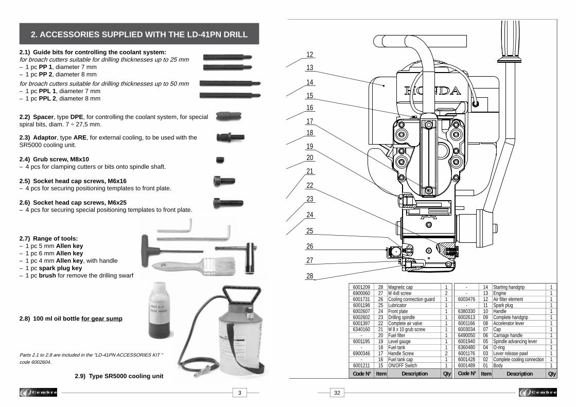
Magnetic capM 4x8 screw Cooling connection guardLubricatorFront plateDrilling spindleComplete air valveM 8 x 10 grub screwFuel fi lterLevel gaugeFuel tankHandle ScrewFuel tank cap ON/OFF Switch
11111111111111
2827262524232221201918171615
2. ACCESSORIES SUPPLIED WITH THE LD-41PN DRILL
12111111111211
--
6003476-
6380330600261360011666003034649005060019406360480600117660014286001489
Item QtyDescriptionCode N°
1413121110090807060504030201
Starting handgripEngineAir fi lter elementSpark plugHandleComplete handgripAccelerator leverCapCarriage handleSpindle advancing leverO-ringLever release pawlComplete cooling connectionBody
Item QtyDescription
60012096900060600173160011986002607600260260013976340160
-6001195
-6900346
-6001211
3 32
2.1) Guide bits for controlling the coolant system:for broach cutters suitable for drilling thicknesses up to 25 mm – 1 pc PP 1, diameter 7 mm– 1 pc PP 2, diameter 8 mm
for broach cutters suitable for drilling thicknesses up to 50 mm – 1 pc PPL 1, diameter 7 mm– 1 pc PPL 2, diameter 8 mm
2.2) Spacer, type DPE, for controlling the coolant system, for specialspiral bits, diam. 7 ÷ 27,5 mm.
2.3) Adaptor, type ARE, for external cooling, to be used with theSR5000 cooling unit.
2.4) Grub screw, M8x10 – 4 pcs for clamping cutters or bits onto spindle shaft.
2.5) Socket head cap screws, M6x16 – 4 pcs for securing positioning templates to front plate.
2.6) Socket head cap screws, M6x25 – 4 pcs for securing special positioning templates to front plate.
2.7) Range of tools:– 1 pc 5 mm Allen key– 1 pc 6 mm Allen key– 1 pc 4 mm Allen key, with handle– 1 pc spark plug key– 1 pc brush for remove the drilling swarf
2.8) 100 ml oil bottle for gear sump
Parts 2.1 to 2.8 are included in the "LD-41PN ACCESSORIES KIT "
code 6002604.
2.9) Type SR5000 cooling unit
13
14
20
21
22
23
24
16
12
15
27
25
26
28
1718
19

Guarantee conditions cease upon usage of non original spare parts.
When ordering spare parts always give the following information:- spare part code- spare part description- drilling machine model- drilling machine serial number
FIG. 33 – LD-41PN DRILL ASSEMBLY
31 4
TDB 6TDB 1
TDB 3
3.1) DBG-F2 device (*) with moving arm for clamp-ing the drill to the rail web and track fi ttings, complete with the following end pieces:– TDB 6: standard end piece for rails and stock rails.– TDB 1: for switch blades and compound frogs.– TDB 3: for repairing (adjusting) existing holes on rails for subsequent application of electrical connec-tions and for additional special applications.
(*) Always supplied with type LD-41P drill.
3.1.1) DBG-LF2 device with moving arm complete with TDB 7 end piece for clamping the drill to girder rails and for additional special applications.
3.2) “VAL LD” metal case for storing the drill complete with the DBG-F2 device and VAL MPA tool case.
3.2.1) “VAL LD-L” metal case for storing the drill complete with the DBG-L F2 device, and VAL MPA tool case.
TDB 7
08
07
10
09
06
05
04
03
02
01
11
3. ACCESSORIES TO BE ORDERED SEPARATELY

3.3) Templates for positioning the drill on rails and stock rails to enable drilling to be carried out according to the provi-sions of railway board standards:
– MPAF UIC54 on DRILLING AXIS of UIC 54 rail– MPAF UIC60 on DRILLING AXIS of UIC 60 rail– MPAFN UIC60 on DRILLING/NEUTRAL AXIS of UIC 60 rail
• Note: Contact Cembre for selection of specifi c application accessories.
3.4) MPAU universal positioning template suitable both for repairing existing holes on various fi ttings, and for drilling disused rails.
3.5) SPA positioning plates for drilling rail heads with a centre-to-centre distance established in the Railway board standards, without the need for marking out; for use in con-junction with MPAF... positioning templates.
3.6) MRF clamp to be applied as a reference to the head of rails for use, in conjunction with SPA... positioning plates, for in-line drilling of rail heads, with established centre-to-centre distance.
3.7) VAL MPA tool case suitable for storing the ac-cessories indicated in 3.3 - 3.6, and the drilling tools.
5 30
FIG. 32 – ENGINE OIL CHANGE
13.2.5) Engine oil change (Ref. to Figs. 31 and 32)
– Drain the used oil when the engine is warm. Warm oil drains quickly and completely.– Check that the fuel fi ller cap is tightened securely.– Place a suitable container below the engine to catch the used oil.– Remove the oil fi ller cap/dipstick and drain the oil into the container by tipping the machine toward the oil fi ller neck. Some oil will remain in the engine after draining, when refi lling with fresh oil, start with less than 80 ml (2.7 US oz). – With the engine in a level position, fi ll to the bottom edge of the oil fi ll hole (Ref. to Fig. 31 and 32) with the recommended oil (see § 1).
– MAX OIL CAPACITY: 100 ml.
Always use the best grade and clean oil.Contaminated oil, poor quality oil and shortage of oil cause damage to engine or shorten the engine life.
Ensure that disposal of used oil is in accordance with current legislation.
13.2.6) Checking of screws.– Check and re-tighten all screws where necessary.
13.3) SPECIAL MAINTENANCE OF THE DRILLThe special maintenance operations require the intervention of qualifi ed personnel only, Please contact Cembre (See § 15).
13.3.1) Storing the drilling machine for long periods.– Completely empty the fuel tank.– Start the engine and let it run until it stops, so that all fuel is exhausted from the machine.– Remove the spark plug.– Pour 3-5 cm3 of oil into the cylinder.– Repeatedly pull gently on the starting rope so that dispersion of oil in the cylinder is achieved and reinstall the spark plug.– Using a clean cloth soaked with motor oil, clean all metal parts of the machine.– Store the drilling machine in its appropriate case or in a dry environment protecting it against accidental damage and dust.
▲!
Initial oil change: fi rst month or after 10 hours of operationThereafter: every 6 months or 50 hours of operation
oil fi ller cap/dipstick

29 6
FIG. 31 – CHECK ENGINE OIL
FIG. 30 – SPARK PLUG CLEANING
13.2.3) Spark plug cleaning (Ref. to Fig. 30)– Using a 4 mm allen key remove the fi xing screw on the top of the red cover.– Disconnect the spark plug wire lead and remove the spark plug with the key supplied. Inspect the spark plug. Replace it if damaged or badly fouled, if the sealing washer is in poor condition, or if the electrode is worn. Measure the spark plug electrode gap, correct the gap if necessary by carefully bending the side electrode. The gap should be: 0.60-0.70 mm (0.024-0.028 in).– Install the spark plug carefully, by hand, to avoid crossthreading. – When installing a new spark plug, tighten 1/2 turn with the key to compress the washer. When reinstalling the original spark plug, tighten 1/8-1/4 turn with the key to compress the washer. A loose spark plug can overheat and damage the engine. Overtightening the spark plug can damage the threads in the cylinder head.– Attach the spark plug cap to the spark plug. Install the top cover, and tighten the fi xing screw.– In case of plug replacement, use type NGK CM5H, CMR5H or equivalents.
13.2.4) Check engine oil (each use) (Ref. to Fig. 31)Before checking or refi lling engine oil, be sure the machine is located on a stable, level surface and stopped.– Remove the oil fi ller cap/dipstick and wipe it clean. – Insert the oil fi ller cap/dipstick without screwing it into the oil fi ller neck, then remove it to check the oil level shown on the dipstick. If the oil level is near or below the lower limit mark on the dipstick, fi ll to the bottom edge of the oil fi ll hole with the recommended oil (see § 1).– Change oil if it is contaminated.– Wipe off any spilled oil before starting the engine.– Reinstall the oil fi ller cap/dipstick and tighten securely.
spark plug
OIL FILL HOLE (bottom edge)
LOWER LIMIT
OIL FILLER CAP/DIPSTICK
LIMITE SUPERIORE
LIMITE SUPERIOREUPPER LIMIT
UPPER LIMIT
Every year or 100 hours of operation
Broach cutter Guide bit
3.8) Broach cutters
* Contact Cembre for this types of broach cutters.
Broach cutters resharpening must be carried out in compliance with appropriate modes of operation which allow the best result.
BROACH CUTTERS FOR RAILS IN STEEL QUALITY 700-900-1100 (UIC 860.0)
A 135A 140 *A 150 *A 160A 170A 180A 190A 200A 210A 220A 230A 240A 250A 260A 270A 280A 290A 300A 310 *A 320A 330A 340 *A 350 *A 360 *A 370 *A 380 *
Ø mm
13,514151617181920212223242526272829303132333435363738
A 160LA 170LA 180LA 190LA 200L *A 210LA 220LA 230LA 240LA 250LA 260LA 270L *A 280LA 290L *A 300LA 310L *A 320LA 330L *A 340L *A 350L *A 360L *A 370L *
A 380L *
MAX DRILLING THICKNESS25 mm
LONG RANGE (L max = 88mm)
Broach cutter Guide bit
SHORT RANGE
Ref. PPL 1
Ref. PPL 2
Ref. PP 1
Ref. PP 2
MAX DRILLING THICKNESS50 mm

Every 100 hours of operation
13.2.1) Fuel fi lter cleaning (Ref. to Fig. 28)– Check that the engine oil fi ller cap is tightened securely.– Remove the fuel fi ller cap, and drain the fuel into an approved gasoline container by tipping the engine toward the fuel fi ller neck.– Pull the fuel fi lter out through the fuel fi ller neck by hooking the black fuel tube with a piece of wire, such as a partly straightened paper clip.– Inspect the fuel fi lter. If the fuel fi lter is dirty, wash it gently with nonfl ammable or high fl ash point solvent. If the fuel fi lter is excessively dirty, replace it.– Remove water and dirt from inside the fuel tank by rinsing it out with non-fl ammable or high fl ash point solvent.– Insert the fuel fi lter into the fuel tank and tighten the fuel fi ller cap securely. Improper use of solvents can result in fi re or explosion.
13.2.2) Air fi lter cleaning (Ref. to Fig. 29)– Press the latch tab (A) on the top of the air cleaner cover and remove the cover. – Clean the fi lter element in warm soapy water, rinse and allow to dry thoroughly, or clean in non fl am- mable solvent and allow to dry.– Dip the fi lter element in clean engine oil, then squeeze out all excess oil. – Wipe dirt from the air cleaner body and cover, using a moist rag. Be careful to prevent dirt from entering the carburettor.– Reinstall the fi lter element and air cleaner cover. Always replace damaged fi lter elements. Operating in dusty condition may require more frequent maintenance than above.Do not operate the engine with air fi lter re-moved.
FIG. 1
FIG. 2
The drilling tools indicated in the table guarantee optimum results. For tools of other types, check the dimensional compatibility (particularly the size of the attachment and the length).
3.10) LR2 BIODEGRADABLE LUBROCOOLANT3 litre container to be used in a 5-10 % solution, for optimum operation of both broach cutters and spiral bits.
3.11) LR3 ANTIFREEZE CONCENTRATE 3 litre added to the lubrocoolant mixture in the right concentration willmaintain the lubrocoolant mixture fl uid in negative temperature conditions.
3l
– The special spiral bits in the PE range allow automatic cooling by means of the SR5000 unit sup- plied with the drilling machine.– All spiral bits in the PE range allow drilling of thicknesses up to 45 mm.
L max
ø
APED...
APE...
ø
L max
h
3.9) Spiral bits
7 28
13.2) ORDINARY MAINTENANCE OF THE COMBUSTION ENGINE
Every 3 months or 25 hours of operation
FIG. 28 – FUEL FILTER CLEANING
FIG. 29 – AIR FILTER CLEANING
fi lter element
fuel fi lter
A
77,18
8,59
9,510111213
13,5
SPECIAL SPIRAL BITS FOR RAILS IN STEEL QUALITY 700 - 900 - 1100 (UIC 860.0)
PE 140PE 160PE 170ARPE 175PE 180PE 190ARPE 210ARPE 220PE 240ARPE 275AR
Ø mm
141617
17,51819212224
27,5
Adaptorref.Fi
gure h
mmL
maxmm
APED 135/165
Spiral Bitref.(*)
PE 70PE 71PE 80PE 85PE 90PE 95 PE 100PE 110PE 120PE 130ARPE 135AR
Ø mm
Adaptorref.
hmm
Lmaxmm
APE 90APE 95 APE 100APE 110APE 120APED 130
Figu
re
1
1
2
(*)
PE
... A
R:
spe
cial
hig
h qu
ality
spi
ral b
it.Spiral Bitref.(*)
1,6
76
76 1,6APED 701,2
88
85
88
APED 80
APED 135/165
7672
1,4

02
1735
03
01
Every 50 hours of operating
13.1.3) Checking of screws.– Check and re-tighten all screws where necessary.
13.1.4) Lubrication (Ref. to Figs. 33 and 34)– Lubricate the spindle support housing by means of the appropriate lubricator (25), the screw of the DBG-F2 clamping device.
13.1.5) Cleaning of coolant fi lter (Ref. to Fig. 27)The coolant system of the drilling machine is provided with anti-impurity fi lter; should a decrease of the fl ow of the lubrocoolant be noticed, it may be necessary to clean it in the following way:– Using a 14mm key, unscrew the coupling (02).– Extract the fi lter and clean it carefully.– Reassemble the fi lter into the coupling (02) as shown in the Fig. 27, fully tighten the coupling.
Detail of the max pressure valve
FIG. 3 – COOLANT UNIT
The type SR5000 coolant unit consists of a tank complete with tube and maximum pres-sure valve (01), fi tted with a pump device for pressurisation, which must be connected to the attachment (35) on the drill by means of its quick-coupling (03).The delivery and shut-off of the lubrocoolant are controlled automatically, when drill-ing with a broach cutter, by the guide bit; when drilling with a spiral bit, delivery and shut-off of the fl uid must be effected manually by operating the tap (02). The use of the lubrocoolant supplied by Cembre, in the recommended concentrations, guarantees optimum use of the drilling tools.Consumption of the lubrocoolant depends both on the variable degree of opening of the tap (02) and the inner pressure of the tank: it is therefore advisable to open the tap a little when the tank is at maximum pressure, while it must be fully opened when the pressure in the tank is low.When using the coolant system, pay careful attention to the instructions on the tank label.
Warning:
● When the tank is not under pressure, check that the bush on the maximum pres- sure valve is screwed right down.
● To fi ll tank with lubrocoolant, turn handle anticlockwise approximately 2 turns to release handle locking mechanism. Remove handle/piston assembly from tank.
01 – Tank complete with hose and max. pressure valve02 – Tap03 – Quick-coupling17 – Vent valve35 – Attachment valve
anti-impurity fi lter
02
27 8
FIG. 27 – CLEANING OF COOLANT FILTER
13.1.2) Removal of metal residues from the crankcaseWhen the drill is positioned as shown in Fig. 26unscrew the cap with magnetic insert (28) on which any metal residues present in the oil will have collected. Carefully clean the magnetic insert with a clean cloth and screw it back into the appropriate housing.
FIG. 26 – REMOVAL OF METAL RESIDUES 28
4. COOLANT UNIT TYPE SR5000

FIG. 4
Before you service or remove parts, stop the engine and allow it to cool. Always remove the spark plug cap from spark plug when servicing the engine to prevent accidental starting.
After the fi rst 10 operating hours, proceed with sump oil change, as follows: (Ref. to Figs. 25 and 25a)– Remove the cap with the magnetic insert (28).– Remove the oil fi ller cap (07).– Make sure that all the oil comes out by tilting slightly the drilling machine in order to make the operation easier.– Clean the cap (28) (see § 13.1.2). – Reassemble the cap.– Fill the oil sump to the level indicator (see § 13.1.1) using the oil supplied with the drilling machine; it will be necessary to use about 100 ml oil.– Replace the oil fi ller cap (07).
Ensure that disposal of used oil is in accordance with current legislation.
13.1) ORDINARY MAINTENANCE OF THE DRILL
Every 20 hours of operation
13.1.1) Topping up oil (Ref. to Figs. 25 and 25a)With the drill switched off and placed on a fl at surface, check the oil level in the crankcase by looking through the transparent inspection cover (19).The level must be approximately half way up the cover; if the level is low, top up the oil by unscrewing the cap (07) at the top of the crankcase and adding the quantity of oil required.
Only use the oil grade recommended in § 1.Never use regenerated or used oil.The oil must be clean.
● The drill is equipped with a coolant attachment valve (35) and a vent valve (17) which are located as shown (Fig. 3). If under certain operating circumstances they need to be interchanged, proceed as follows: – Using a 17 mm hexagonal spanner unscrew the vent valve from its seat. – Using the 4 mm allen key provided with the drill, remove the appropriate coolant valve from its seat and fi t into the vent valve seat. – Fit the vent valve into the vacant coolant valve seat.
● When temperatures fall below 0° C the lubrocoolant may freeze which could cause damage to the seals contained in the drill coolant system. It is therefore advisable, when storing the drilling machine, to empty the lu- brocoolant system completely. Proceed as follows (Fig. 4): – Disconnect the quick coupling (03) from the coolant attachment (35) on the drilling machine. – Tilt the machine so that the coolant attachment is at its lowest point - allowing for natural drainage. – Operate the advancing lever (36) to advance and retract the drilling spindle. – Gently shake the machine to expel all fl uid.
ARE adaptor
FIG. 5 – ARE ADAPTOR
4.1) ARE adaptorFor use with type SR5000 coolant unit. The ARE adaptor is inserted in the quick-coupling of the tank tube (Ref. to Fig. 5), it may be used to provide manual external cooling when cutters are used to enlarge existing holes, or when using spiral bits not de-signed for automatic cooling.If necessary the ARE adaptor can also be used to clean various parts of the drill, by means of the lubrocoolant pressure jet, e.g. parts such as the tool clamping seat in the spindle shaft, seats for the jig fi xing screws, etc.
35
36
03
9 26
07
19
28
FIG. 25
FIG. 25a
�
13. MAINTENANCE

FIG. 6
FIG. 7
The spindle is advanced by moving the lever (36) (See Fig. 6 a). The lever is fi t-ted with a release pawl (39) which, when pressed, renders it independent of the hub and hence the spindle; the opera-tor can therefore easily vary the angular position of the lever without movement of the spindle (Fig.6).
6c - With the hub released, moving the lever towards the operator produces a cor- responding advance of this spindle.
6a - Moving the lever (36) towards the operator produces a corresponding advance of the spindle.
5.1) Adjustment of the advance lever
The movement of the lever must never be loose, for adjustment proceed to tighten it by loading the cup springs by means of the as-sociated self-locking nut, after removing the protective cap (see Fig. 7).
6b - With the release pawl (39) pressed, the le ver is released from its hub and can repeat the previous travel without the spindle moving.
36
25 10
LD-41P
VAL MPA
VAL LD
When work has been completed, put away the drill by proceeding as follows:
12.1) Depressurise the tank of the SR5000 cooling unit (see § 4), close the tap (02) on the tube from the tank, and disconnect the quick-coupling (03).
12.2) Carefully clean the drill, particularly in the spindle area, removing machining waste (swarf, etc.) and any deposits of lubricating coolant.
12.3) Fully withdraw the spindle.
12.4) Place the drill and the SR5000 cooling unit in a sealed place free from dust, mois- ture and the risk of accidental impact.
For better protection Cembre recommends the use of the VAL LD metal case designed for this purpose (see § 3.2). The DBG-F2 moving arm device allows the drill to be housed and locked in the case. A suitable housing is also provided in this VAL LD for the VAL MPA case containing the most commonly used accessories.
12. STORING THE DRILL 5. SPINDLE ADVANCE LEVER

07
18Guide bit PP...
Guide bit PPL ...
STOP THE ENGINE when servicing the drill: before removing the broach cutters, spiral bits, positioning templates etc.
6.1) Assembling broach cutters (Ref. to Figs. 8-11).6.1.1) Insert the guide bit in the cutter from the side of the spigot.6.1.2) Using the lever (36), position the spindle shaft (07) so that both grub screws (18) become accessible and suffi cient space is provided to insert the cutter; if necessary rotate the spindle shaft manually and suffi ciently by inserting the 4 mm male hexagon key in the appropriate intermediate gear housing (33) in the crankcase of the drill corresponding to the feed handle (71) (see Fig. 11).6.1.3) Insert the cutter in the spindle shaft so that the two engaging dogs on the cutter spigot line up with the grub screws (18).6.1.4) Clamp the cutter by fully tightening the grub screws by means of the 4 mm male hexagon key.6.1.5) Check that the guide bit slides freely by applying slight pressure on it.
6.2) Assembling spiral bits (Ref. to Figs. 9 - 11)6.2.1) Using the advance lever, position the spindle shaft so that both grub screws be- come accessible and suffi cient space is provided to insert the spiral bit; if necessary rotate the spindle shaft manually and suffi ciently by inserting the 4 mm male hexa- gon key in the appropriate intermediate gear housing in the crankcase of the drill corresponding to the feed handle (see Fig. 11).
FIG. 8 – ASSEMBLING BROACH CUTTERS
Short type broach cutterMaximum drilling thickness: 25 mm
Long type broach cutterMaximum drilling thickness: 50 mm
Engaging dogs
11 24
�a)
b)
e)
c)
NOTE: the engine will perform at its optimum after a "running-in" peri-od of approximately 200 drilling operations.
d)
Before starting the engine, ensure that: - the spindle shaft is fully retracted. - the accelerator control lever is positioned at the low speed position "0".
11.1) Set the engine "ON/OFF" switch to the "ON" position (Fig. a).11.2) Set the choke lever to the CLOSED position; when engine is warm or in the case of high ambient temperatures, this lever may require setting to the OPEN position (Fig. b).11.3) Keeping the accelerator control lever at the low speed position, press the priming bulb repeatedly until fuel can be seen in the clear-plastic fuel-return tube (Fig. c).11.4) Pull the starter grip lightly until resistance is felt, then pull briskly (Fig. d). Return the starter grip gently. Do not pull the rope out all the way.Do not allow the starter grip to snap back against the engine, return it gently to prevent damage to the starter.11.5) If the choke lever was moved to the CLOSEDposition to start the engine, gradually move it to the OPEN position as the engine warms up (Fig. e).11.6) Keep the engine “warming up” for at least 3 minutes before starting any actual drilling.11.7) To stop the engine, set the accelerator lever at the low speed position and allow the engine to run at low speed for 2 or 3 minutes before stopping. Set the "ON/OFF" switch to the "OFF" position.
11. STARTING THE ENGINE6. PREPARING THE DRILL
33
71
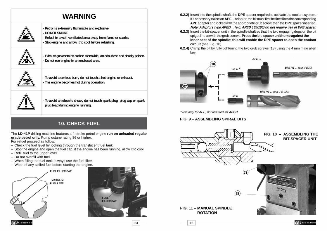
6.2.2) Insert into the spindle shaft, the DPE spacer required to activate the coolant system. If it necessary to use an APE... adaptor, the bit must fi rst be fi tted into the corresponding APE adaptor and locked with the appropriate grub screw, then the DPE spacer inserted. Note: Adaptors type APED… (e.g. APED 135/165) do not require use of DPE spacer.6.2.3) Insert the bit-spacer unit in the spindle shaft so that the two engaging dogs on the bit spigot line up with the grub screws. Press the bit-spacer unit home against the inner seat of the spindle: this will enable the DPE spacer to open the coolant circuit (see Fig. 10).6.2.4) Clamp the bit by fully tightening the two grub screws (18) using the 4 mm male allen key.
FIG. 10 – ASSEMBLING THE BIT-SPACER UNIT
FIG. 9 – ASSEMBLING SPIRAL BITS
FIG. 11 – MANUAL SPINDLE ROTATION
07
18DPE *
DPE
Bits PE ... (e.g. PE70)
Bits PE ... (e.g. PE 220)
APE ...
* use only for APE, not required for APED
23 12
The LD-41P drilling machine features a 4-stroke petrol engine run on unleaded regular grade petrol only. Pump octane rating 86 or higher. For refuel proceed as follow:– Check the fuel level by looking through the translucent fuel tank.– Stop the engine and open the fuel cap, if the engine has been running, allow it to cool.– Refi ll fuel to the upper level. – Do not overfi ll with fuel.– When fi lling the fuel tank, always use the fuel fi lter.– Wipe off any spilled fuel before starting the engine.
FUEL FILLER CAP
10. CHECK FUEL
WARNING
- Petrol is extremely fl ammable and explosive. - DO NOT SMOKE. - Refuel in a well ventilated area away from fl ame or sparks.- Stop engine and allow it to cool before refueling.
- Exhaust gas contains carbon monoxide, an odourless and deadly poison. - Do not run engine in an enclosed area.
- To avoid a serious burn, do not touch a hot engine or exhaust.- The engine becomes hot during operation.
- To avoid an electric shock, do not touch spark plug, plug cap or spark plug lead during engine running.
TAPPO SERBATOIO
LIVELLO SUPERIORE
FUEL FILLER CAP
MAXIMUM FUEL LEVEL

7. DRILL TYPE LD-41P
02
FIG. 24 – POSITIONING
02
FIG. 12 – DRILL TYPE LD-41P
referencepin TDB 3
TDB 6
M 8x25 screwsand spring washers
For clarity the drill is not shown in the fi gures
Reference point for distances
Reference point for distances
Part code LD-41P consist of the LD-41PN basic drill (see page 1) complete with the DBG-F2 moving arm device for clamping to the rail web and track fi ttings (Ref. to Fig. 12).
The DBG-F2 clamping device consists of:– Clamping unit– Type TDB 1 end piece– Type TDB 3 end piece– Type TDB 6 standard end piece– Socket head cap screws M8x25 (2 pcs)– Spring washers (4 pcs)– Reference pin
13 22
TDB 1

TDB 6 end piece for rails and stock rails
Seats to be used for special applications.
FIG. 13 – ASSEMBLY OF END PIECES
holdingplate
7.1) Assembling the end piecesTDB 1, TDB 6 and TDB 3 end pieces of the DBG-F2 device, with moving arm, have been designed for adaptation to the different operating conditions on rails and track fi ttings; their assembly is shown in Fig. 13.• When assembling the TDB 3 end piece ensure that the positioning pawl is pointing downward in relation to the bolt.• When disassembling the TDB 6 end piece ensure that, after removing the pivot, the complete assembly is slid away downward without acting on the holding plate.• Over-advancing the spindle after drilling must be avoided when using the TDB 1 and TDB 3 end pieces.
7.2) Assembly of the DBG-F2 clamping device on the drillThe DBG-F2 clamping device is fi tted to the front plate of the drill, centred by means of the reference pin supplied and secured with the two socket head cap screws M8x25 (35) also supplied. The assembly is illustrated in Fig. 14.
9.2) Drilling in line with rail heads (Ref. to Figs. 23-24)9.2.1) Fit the MPAF... positioning template corresponding to the rail to be drilled (see § 7.3 or 9.1).9.2.2) Fit the MRF clamp on the head of the rail, keeping it in contact with the rail head at the reference point of the drilling centres. Lock it in position with the lever. The lever is provided with a return pushbutton for moving in any direction after locking. (See Fig. 23)9.2.3) Insert the SPA... positioning plate so that the curved part is facing upwards.9.2.4) Insert the locking pin (02) in one of the two holes of the connection plate.9.2.5) With the spindle fully withdrawn, position the drill close to the MRF clamp, without locking the spindle.9.2.6) Slide the drill so that: – the curved end of the SPA... plate is fl ush against the MRF clamp on the side identifying the reference point for distances. – the MPAF... positioning template is fl ush against the locking bolt (02) (see Fig. 24).9.2.7) Clamp the drill in this position by tightening the handwheel fully, and commence drilling (see § 8.1).9.2.8) To drill the second hole in the rail, repeat operations 9.2.6 - 7 with the locking pin (02) inserted in the second hole of the SPA... plate.
FIG. 23 – ASSEMBLY OF MRF CLAMP
21 14
TDB 3 end piece for enlarging existing holeson rails inherent in the application of electrical connections and foradditional special applications.
positioning pawl pointing downwards
TDB 1 end piece for switch blades and composite frogs

FIG. 14 – ASSEMBLY OF DBG-F2 CLAMPING DEVICE
screws M6x16MPAF...
MPAU
DBG-F2
Drilling machine front plate
35
reference pin
22
FIG. 15 – ASSEMBLY OF TEMPLATES
7.3) Assembly of positioning templates (Ref. to Fig. 15)
7.3.1) The type MPAF.. and MPAU positioning templates are secured to the front plate (22) of the drill by means of the two screws M 6x16 supplied.
FIG. 21
02
03
9.1) Instruction for drilling close to rail heads
FIG. 22 – POSITIONING
02
For clarity the drill is not shown in the fi gures
9.1.1) Fit the MPAF... positioning template corresponding to the rail to be drilled (see § 7.3).9.1.2) Insert the SPA... positioning plate (03) relating to the rail to be drilled in the appro- priate housing (see Fig. 21).9.1.3) Insert the locking pin (02) in one of the two holes of the positioning plate.9.1.4) With the spindle fully withdrawn, position the drill close to the rail head without clamping it.9.1.5) Slide the drill so that: – the curved end of the SPA... positioning plate is fl ush against the rail head. – the MPAF... positioning template is fl ush against the locking bolt (02).9.1.6) Clamp the drill in this position by tightening the handwheel fully, and commence drilling (see § 8.1).9.1.7) To drill the second hole in the rail, repeat operations 9.1.5 - 6 with the locking pin (02) inserted in the second hole of the SPA... positioning plate.
15 20
9. SPA... POSITIONING PLATE
ads

FIG. 16 – POSITIONING THE DRILLFIG. 20 – COOLING DRILLING WITH SPIRAL BIT
7.4) Clamping to the rail web (Ref. to Fig. 16)The drill has a rapid rail engagement/release mechanism and specially shaped positioningtemplates for each rail type which facilitate precise and certain location of the part to be drilled. To fully exploit the special features of the engagement device, we recommend calibrating it to the rail type to be drilled as follows:– Withdraw the spindle shaft (07) completely by means of the lever (36).– Insert the threaded bush (39) of screw (11) into its seat (A) in the mobile arm (17) (see detail in Fig. 16); use the hand-wheel (12) to completely open the mobile arm.– Place the drill on the track at the point to be drilled and clamp it by tightening the hand-wheel fully down (12): the positioning template will automatically position the cutter or drill bit in line with the designated axis; if precise positioning is necessary to the longitudinal track axis, use the reference pin (18).– For rapid drill release, simply back-off the hand-wheel (12) by approximately two complete turns, and while supporting the drill by its grip (09), pull the handwheel towards you. The threaded bush (39) will disengage the seat (A) in the mobile arm (17) which will open automatically, freeing the drill. In this way, the operator can rapidly remove the machine from the track in case of danger, or move on to drill another hole. Thus, the next track engagement operation will be considerably simplifi ed: after positioning the drill at the point to be drilled, simply push the hand-wheel forward so that the threaded bush engages the seat (A) of the mobile arm. Now, a few turns on the hand-wheel will be suffi cient to engage the drill correctly on the track.
Start drillingwith discharge oflubrocoolant
Drilling
Finish drillingwith removal of swarf andswitching off oflubrocoolant
Approach
FIG. 19 – COOLANT DRILLING WITH BROACH CUTTER
8.3) Drill fi tted with special spiral bitFollow the sequence described in § 8.1, taking care to position the drill on the rail by keep-ing the spindle fully withdrawn. Bear in mind that the coolant circuit, instead of being automatically opened and closed by the guide bit, is kept open at all times by the DPE spacer fi tted on the spigot of the spiral bit; it must therefore be activated, by opening the tap (02), before starting to drill, then switched off after drilling by closing the tap.
FIG. 20bPE 170 - PE 275 spiral bits(drilling diameters from 17 to 27,5 mm)
FIG. 20aPE 70 - PE 165 spiral bits(drilling diameters from 7 to 16,5 mm)
DPE spacer APE adapter Spiral bit
19 16
11
03
36
18
07
➟
➟
39
11 17
A
1739
11

� Check engine oil level before operation (see § 13.2.4). Switch on the cooling system before starting the drill (see § 4).
8.1) Drill fi tted with “short” type broach cutter (for drilling thicknesses of up to 25 mm).The drilling sequence may be started with the drill fi tted with the broach cutter (§ 6.1), clamping end piece (§ 7.1), positioning template (§ 7.3), the drill being clamped to the rail (§ 7.4), as follows:8.1.1) Connect the female quick-coupling of the SR5000 coolant unit to the male cou- pling (35) on the drill.8.1.2) Open the tap (02) fi tted on the coolant unit hose.8.1.3) Using the lever (36) bring the guide bit almost in contact with the rail (Fig. 17a); keeping the release pawl (39) pressed, release the lever from its cup and return it to the initial position (Fig. 17b), which will enable the travel of the lever (36) to be used in the most advantageous way.
8.1.4) Start the engine, following instructions § 11. 8.1.5) Proceed to drill by initially applying light pressure on the lever (36), increasing the pressure progressively, avoiding jolts, and fi nally relieving the pressure in the exit phase. When drilling close to raised markings on the rail the initial pressure must be extremely light until the markings disappear, otherwise the cutter may be damaged.8.1.6) The guide bit will enable the lubrocoolant to be discharged throughout the drilling process.8.1.7) When drilling has been completed, fully retract the spindle, stop the motor by pressing the switch to "OFF" position, and make sure that drilling swarf is removed before recommencing drilling.8.1.8) After drilling it is advisable to remove with the brush all swarf from the broach cutter or spiral bit and spindle area.
8.2) Drill fi tted with “long” type broach cutter (for drilling thicknesses of up to 50 mm). Follow the sequence described in § 8.1, taking care to position the drill on the rail by keeping the spindle fully withdrawn.
FIG. 17 – DRILLING
Fig. 17c
Fig. 17a
Fig. 17b
36
39
17 18
FIG. 18 – DRILLING
11
02
35
39
36
8. DRILLING


![Armstrong Floor Products - Technical Information Product Technology No. 2.1, Issue 04_2009 [41p]](https://img.pdfslide.net/doc/110x75/55cf94e9550346f57ba546b0/armstrong-floor-products-technical-information-product-technology-no-21.jpg)


![DOCUMENT RESUME ED 052 776 JC 710 200 [71] 41p](https://img.pdfslide.net/doc/110x75/6270e26a0308ed5de924dcd8/document-resume-ed-052-776-jc-710-200-71-41p.jpg)

![AlphaBetaSeriesChinaIndepth 41p]](https://img.pdfslide.net/doc/110x75/577d27dc1a28ab4e1ea5084f/alphabetaserieschinaindepth-41p.jpg)