Embed Size (px)
Citation preview

Bosch Motorsport | Engine Control Unit MS 12
Engine Control Unit MS 12
www.bosch-motorsport.com
u 12 injection output stages
u For piezo injectors
u 78 data inputs
The MS 12 is the high-end ECU for Diesel engines. ThisECU offers 12 Piezo injection power stages for use inup to a 12 cylinder engine. Various engine and chassisparameters can be measured with a high number of in-put channels. All measured data can be transferred viaFireWire interface to an optional flash card data log-ger. Gear box control strategies are optional.
Application
Engine layout Max. 12 cyl.
Injector type Piezo injectors
Control strategy Quantity based
Injection timing 2 pilot injections1 main injection1 post injection
Turbo boost control (incl. VTG) Single or Twin-Turbo
Lambda measurement
Traction control
Launch control
Gear cut for sequential gearbox
Gearbox control
Speed limiter
Optional function packages available
Interface to Bosch Data Logging System
Max. vibration Vibration profile 1 (see Appendixor www.bosch-motorsport.com)
Technical Specifications
Mechanical Data
Aluminum housing
5 connectors in motorsport technology with high pin density, 242 pins
Each connector individually filtered.
Vibration damped circuit boards
8 housing fixation points
Size 240 x 200 x 57 mm
Protection Classification IP67 to DIN 40050, Section 9, Is-sue 2008
Weight 2,500 g
Temperature range -20 to 85°C
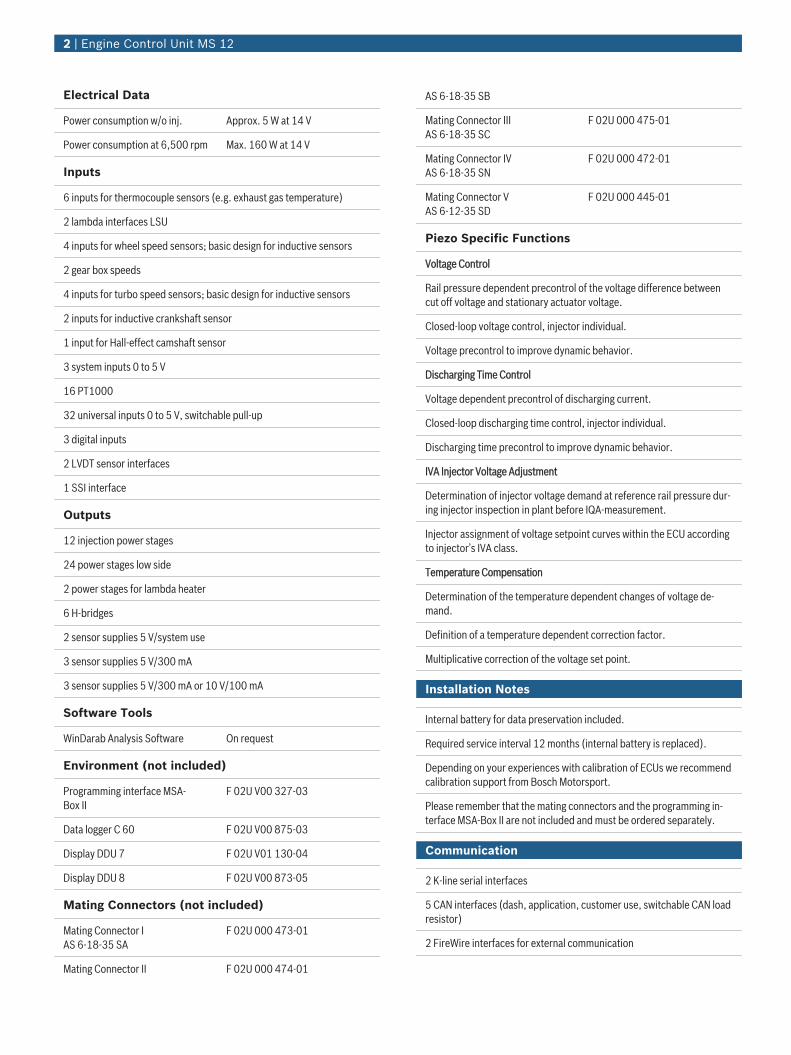
Electrical Data
Power consumption w/o inj. Approx. 5 W at 14 V
Power consumption at 6,500 rpm Max. 160 W at 14 V
Inputs
6 inputs for thermocouple sensors (e.g. exhaust gas temperature)
2 lambda interfaces LSU
4 inputs for wheel speed sensors; basic design for inductive sensors
2 gear box speeds
4 inputs for turbo speed sensors; basic design for inductive sensors
2 inputs for inductive crankshaft sensor
1 input for Hall-effect camshaft sensor
3 system inputs 0 to 5 V
16 PT1000
32 universal inputs 0 to 5 V, switchable pull-up
3 digital inputs
2 LVDT sensor interfaces
1 SSI interface
Outputs
12 injection power stages
24 power stages low side
2 power stages for lambda heater
6 H-bridges
2 sensor supplies 5 V/system use
3 sensor supplies 5 V/300 mA
3 sensor supplies 5 V/300 mA or 10 V/100 mA
Software Tools
WinDarab Analysis Software On request
Environment (not included)
Programming interface MSA-Box II
F 02U V00 327-03
Data logger C 60 F 02U V00 875-03
Display DDU 7 F 02U V01 130-04
Display DDU 8 F 02U V00 873-05
Mating Connectors (not included)
Mating Connector IAS 6-18-35 SA
F 02U 000 473-01
Mating Connector II F 02U 000 474-01
AS 6-18-35 SB
Mating Connector IIIAS 6-18-35 SC
F 02U 000 475-01
Mating Connector IVAS 6-18-35 SN
F 02U 000 472-01
Mating Connector VAS 6-12-35 SD
F 02U 000 445-01
Piezo Specific Functions
Voltage Control
Rail pressure dependent precontrol of the voltage difference betweencut off voltage and stationary actuator voltage.
Closed-loop voltage control, injector individual.
Voltage precontrol to improve dynamic behavior.
Discharging Time Control
Voltage dependent precontrol of discharging current.
Closed-loop discharging time control, injector individual.
Discharging time precontrol to improve dynamic behavior.
IVA Injector Voltage Adjustment
Determination of injector voltage demand at reference rail pressure dur-ing injector inspection in plant before IQA-measurement.
Injector assignment of voltage setpoint curves within the ECU accordingto injector’s IVA class.
Temperature Compensation
Determination of the temperature dependent changes of voltage de-mand.
Definition of a temperature dependent correction factor.
Multiplicative correction of the voltage set point.
Installation Notes
Internal battery for data preservation included.
Required service interval 12 months (internal battery is replaced).
Depending on your experiences with calibration of ECUs we recommendcalibration support from Bosch Motorsport.
Please remember that the mating connectors and the programming in-terface MSA-Box II are not included and must be ordered separately.
Communication
2 K-line serial interfaces
5 CAN interfaces (dash, application, customer use, switchable CAN loadresistor)
2 FireWire interfaces for external communication
2 | Engine Control Unit MS 12
Ordering Information
Engine Control Unit MS 12Order number on request
3 | Engine Control Unit MS 12
Represented by:
Europe: North America: Latin America: Asia-Pacific: Australia, New Zealand and South Africa:Bosch Engineering GmbHMotorsportRobert-Bosch-Allee 174232 AbstattGermanyTel.: +49 7062 911 9101Fax: +49 7062 911 [email protected]
Bosch Engineering North AmericaMotorsport38000 Hills Tech DriveFarmington Hills, MI 48331-3417United States of AmericaTel.: +1 248 876 2977Fax: +1 248 876 [email protected]
Robert Bosch LtdaMotorsportAv Juscelino Kubitscheck deOliveira 11800Zip code 81460-900Curitiba - ParanaBrasiliaTel.: +55 41 3341 2057Fax: +55 41 3341 2779
Bosch Engineering Japan K.K.Motorsport18F Queen’s Tower C, 2-3-5 Minato MiraiNishi-ku, Yokohama-shiKanagawa 220-6218JapanTel.: +81 45 650 5610Fax: +81 45 650 5611www.bosch-motorsport.jp
Robert Bosch Pty. LtdMotorsport1555 Centre RoadClayton, Victoria, 3168AustraliaTel.: +61 (3) 9541 [email protected]
© Bosch Engineering GmbH 2015 | Data subject to change without notice2775846411 | en, V3, 23. Oct 2015


![[DESIGN] Piezo-Piezo to Pie](https://img.pdfslide.net/doc/110x75/5571f8bb49795991698df909/design-piezo-piezo-to-pie.jpg)