Embed Size (px)
Citation preview
ENGINE
C
D
E
SECTION ECA
EC
ENGINE CONTROL SYSTEM
F
G
H
I
J
K
L
M
N
O
P
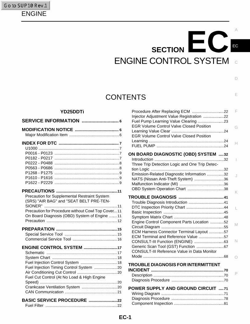
CONTENTS
YD25DDTi
SERVICE INFORMATION ............................ 6
MODIFICATION NOTICE .................................... 6Major Modification Item .............................................6
INDEX FOR DTC ................................................. 7U1000 ........................................................................7P0016 - P0123 ..........................................................7P0182 - P0217 ..........................................................7P0222 - P0488 ..........................................................8P0563 - P0686 ..........................................................8P1268 - P1275 ..........................................................9P1610 - P1616 ..........................................................9P1622 - P2229 ..........................................................9
PRECAUTIONS ..................................................11Precaution for Supplemental Restraint System (SRS) "AIR BAG" and "SEAT BELT PRE-TEN-SIONER" .................................................................11Precaution for Procedure without Cowl Top Cover ....11On Board Diagnosis (OBD) System of Engine ........11Precaution ...............................................................12
PREPARATION ..................................................15Special Service Tool ...............................................15Commercial Service Tool ........................................16
ENGINE CONTROL SYSTEM ............................17Schematic ...............................................................17System Chart ..........................................................18Fuel Injection Control System .................................18Fuel Injection Timing Control System .....................20Air Conditioning Cut Control ....................................20Fuel Cut Control (At No Load & High Engine Speed) .....................................................................20Crankcase Ventilation System ................................20CAN Communication ...............................................21
BASIC SERVICE PROCEDURE ........................22Fuel Filter ................................................................22
Procedure After Replacing ECM .............................22Injector Adjustment Value Registration ...................22Fuel Pump Learning Value Clearing ........................23EGR Volume Control Valve Closed Position Learning Value Clear ...............................................24EGR Volume Control Valve Closed Position Learning ...................................................................24FUEL PUMP ............................................................24
ON BOARD DIAGNOSTIC (OBD) SYSTEM ....32Introduction ..............................................................32Three Trip Detection Logic and One Trip Detec-tion Logic .................................................................32Emission-Related Diagnostic Information ................32NATS (Nissan Anti-Theft System) ...........................36Malfunction Indicator (MI) ........................................36OBD System Operation Chart .................................38
TROUBLE DIAGNOSIS ....................................41Trouble Diagnosis Introduction ................................41DTC Inspection Priority Chart ..................................44Basic Inspection ......................................................45Symptom Matrix Chart .............................................48Engine Control Component Parts Location .............52Circuit Diagram ........................................................55ECM Harness Connector Terminal Layout ..............57ECM Terminal and Reference Value .......................57CONSULT-III Function (ENGINE) ...........................63Generic Scan Tool (GST) Function .........................67CONSULT-III Reference Value in Data Monitor Mode ........................................................................68
TROUBLE DIAGNOSIS FOR INTERMITTENT INCIDENT ..........................................................70
Description ...............................................................70Diagnosis Procedure ...............................................70
POWER SUPPLY AND GROUND CIRCUIT ....71Wiring Diagram ........................................................71Diagnosis Procedure ...............................................78Component Inspection .............................................81
EC-1
Ground Inspection .................................................. 81
DTC U1000 CAN COMMUNICATION LINE ...... 83Description .............................................................. 83On Board Diagnosis Logic ...................................... 83DTC Confirmation Procedure ................................. 83Wiring Diagram ....................................................... 84Diagnosis Procedure .............................................. 84
DTC P0016 CKP - CMP CORRELATION ......... 85On Board Diagnosis Logic ...................................... 85DTC Confirmation Procedure ................................. 85Diagnosis Procedure .............................................. 85
DTC P0088 FUEL SYSTEM .............................. 87On Board Diagnosis Logic ...................................... 87DTC Confirmation Procedure ................................. 87Diagnosis Procedure .............................................. 87Removal and Installation ........................................ 88
DTC P0089 FUEL PUMP ................................... 89On Board Diagnosis Logic ...................................... 89DTC Confirmation Procedure ................................. 89Diagnosis Procedure .............................................. 89Removal and Installation ........................................ 90
DTC P0093 FUEL SYSTEM .............................. 91On Board Diagnosis Logic ...................................... 91Overall Function Check .......................................... 91Diagnosis Procedure .............................................. 92Component Inspection ............................................ 92Removal and Installation ........................................ 93
DTC P0101 MAF SENSOR ................................ 94Component Description .......................................... 94CONSULT-III Reference Value in Data Monitor Mode ....................................................................... 94On Board Diagnosis Logic ...................................... 94DTC Confirmation Procedure ................................. 94Wiring Diagram ....................................................... 96Diagnosis Procedure .............................................. 99Component Inspection ...........................................101Removal and Installation .......................................102
DTC P0102, P0103 MAF SENSOR ................. 103Component Description .........................................103CONSULT-III Reference Value in Data Monitor Mode ......................................................................103On Board Diagnosis Logic .....................................103DTC Confirmation Procedure ................................103Wiring Diagram ......................................................104Diagnosis Procedure .............................................107Component Inspection ...........................................109Removal and Installation .......................................110
DTC P0112, P0113 IAT SENSOR ................... 111Component Description .........................................111On Board Diagnosis Logic .....................................111DTC Confirmation Procedure ................................111Wiring Diagram ......................................................112Diagnosis Procedure .............................................112
Component Inspection .......................................... 114Removal and Installation ....................................... 114
DTC P0117, P0118 ECT SENSOR ...................115Description ............................................................ 115On Board Diagnosis Logic .................................... 115DTC Confirmation Procedure ................................ 115Wiring Diagram ..................................................... 116Diagnosis Procedure ............................................. 116Component Inspection .......................................... 118Removal and Installation ....................................... 118
DTC P0122, P0123 APP SENSOR ..................119Description ............................................................ 119CONSULT-III Reference Value in Data Monitor Mode ..................................................................... 119On Board Diagnosis Logic .................................... 119DTC Confirmation Procedure ................................ 119Wiring Diagram ..................................................... 120Diagnosis Procedure ............................................. 121Component Inspection .......................................... 123Removal and Installation ....................................... 123
DTC P0182, P0183 FUEL PUMP TEMPERA-TURE SENSOR ................................................124
Description ............................................................ 124CONSULT-III Reference Value in Data Monitor Mode ..................................................................... 124On Board Diagnosis Logic .................................... 124DTC Confirmation Procedure ................................ 124Wiring Diagram ..................................................... 125Diagnosis Procedure ............................................. 125Removal and Installation ....................................... 127
DTC P0192, P0193 FRP SENSOR ...................128Description ............................................................ 128CONSULT-III Reference Value in Data Monitor Mode ..................................................................... 128On Board Diagnosis Logic .................................... 128DTC Confirmation Procedure ................................ 128Wiring Diagram ..................................................... 129Diagnosis Procedure ............................................. 130Component Inspection .......................................... 131Removal and Installation ....................................... 131
DTC P0200 FUEL INJECTOR ..........................132On Board Diagnosis Logic .................................... 132DTC Confirmation Procedure ................................ 132Diagnosis Procedure ............................................. 132
DTC P0201 - P0204 FUEL INJECTOR ............133Component Description ........................................ 133CONSULT-III Reference Value in Data Monitor Mode ..................................................................... 133On Board Diagnosis Logic .................................... 133DTC Confirmation Procedure ................................ 133Wiring Diagram ..................................................... 134Diagnosis Procedure ............................................. 136Component Inspection .......................................... 137Removal and Installation ....................................... 137
EC-2

C
D
E
F
G
H
I
J
K
L
M
C
A
N
O
P
E
DTC P0217 ENGINE OVER TEMPERATURE ..138Description ............................................................ 138CONSULT-III Reference Value in Data Monitor Mode ..................................................................... 138On Board Diagnosis Logic .................................... 138Overall Function Check ......................................... 139Wiring Diagram ..................................................... 141Diagnosis Procedure ............................................. 141Main 12 Causes of Overheating ............................ 145Component Inspection .......................................... 145
DTC P0222, P0223 APP SENSOR .................. 147Description ............................................................ 147CONSULT-III Reference Value in Data Monitor Mode ..................................................................... 147On Board Diagnosis Logic .................................... 147DTC Confirmation Procedure ................................ 147Wiring Diagram ..................................................... 148Diagnosis Procedure ............................................. 149Component Inspection .......................................... 150Removal and Installation ....................................... 151
DTC P0335 CKP SENSOR .............................. 152Description ............................................................ 152CONSULT-III Reference Value in Data Monitor Mode ..................................................................... 152On Board Diagnosis Logic .................................... 152DTC Confirmation Procedure ................................ 152Wiring Diagram ..................................................... 153Diagnosis Procedure ............................................. 154Component Inspection .......................................... 156Removal and Installation ....................................... 156
DTC P0336 CKP SENSOR .............................. 157Description ............................................................ 157CONSULT-III Reference Value in Data Monitor Mode ..................................................................... 157On Board Diagnosis Logic .................................... 157DTC Confirmation Procedure ................................ 157Wiring Diagram ..................................................... 158Diagnosis Procedure ............................................. 159Component Inspection .......................................... 161Removal and Installation ....................................... 162
DTC P0340 CMP SENSOR .............................. 163Description ............................................................ 163On Board Diagnosis Logic .................................... 163DTC Confirmation Procedure ................................ 163Wiring Diagram ..................................................... 164Diagnosis Procedure ............................................. 165Component Inspection .......................................... 166Removal and Installation ....................................... 167
DTC P0341 CMP SENSOR .............................. 168Description ............................................................ 168On Board Diagnosis Logic .................................... 168DTC Confirmation Procedure ................................ 168Wiring Diagram ..................................................... 169Diagnosis Procedure ............................................. 170Component Inspection .......................................... 172
Removal and Installation .......................................172
DTC P0380 GLOW RELAY ............................. 173On Board Diagnosis Logic .....................................173DTC Confirmation Procedure ................................173Wiring Diagram ......................................................174Diagnosis Procedure .............................................174Component Inspection ...........................................176
DTC P0403 EGR SYSTEM ............................. 177Description .............................................................177CONSULT-III Reference Value in Data Monitor Mode ......................................................................178On Board Diagnosis Logic .....................................178DTC Confirmation Procedure ................................178Wiring Diagram ......................................................179Diagnosis Procedure .............................................180Removal and Installation .......................................183
DTC P0405, P0406 EGR SENSOR ................. 184Description .............................................................184CONSULT-III Reference Value in Data Monitor Mode ......................................................................185On Board Diagnosis Logic .....................................185DTC Confirmation Procedure ................................185Wiring Diagram ......................................................186Diagnosis Procedure .............................................187Removal and Installation .......................................189
DTC P0409 EGR SYSTEM ............................. 190Description .............................................................190CONSULT-III Reference Value in Data Monitor Mode ......................................................................191On Board Diagnosis Logic .....................................191DTC Confirmation Procedure ................................191Wiring Diagram ......................................................192Diagnosis Procedure .............................................193Removal and Installation .......................................195
DTC P0488 EGR SYSTEM ............................. 196Description .............................................................196CONSULT-III Reference Value in Data Monitor Mode ......................................................................197On Board Diagnosis Logic .....................................197DTC Confirmation Procedure ................................197Wiring Diagram ......................................................198Diagnosis Procedure .............................................199Removal and Installation .......................................200
DTC P0563 BATTERY VOLTAGE .................. 201On Board Diagnosis Logic .....................................201DTC Confirmation Procedure ................................201Diagnosis Procedure .............................................201
DTC P0606 ECM ............................................. 203Description .............................................................203On Board Diagnosis Logic .....................................203DTC Confirmation Procedure ................................203Diagnosis Procedure .............................................203
DTC P0628, P0629 FUEL PUMP ...................
EC-3
Description .............................................................205CONSULT-III Reference Value in Data Monitor Mode ......................................................................205On Board Diagnosis Logic .....................................205DTC Confirmation Procedure ................................205Wiring Diagram ......................................................206Diagnosis Procedure .............................................207Component Inspection ...........................................208Removal and Installation .......................................209
DTC P0642, P0643 SENSOR POWER SUP-PLY .................................................................. 210
On Board Diagnosis Logic .....................................210DTC Confirmation Procedure ................................210Wiring Diagram ......................................................211Diagnosis Procedure .............................................212
DTC P0652, P0653 SENSOR POWER SUP-PLY .................................................................. 214
On Board Diagnosis Logic .....................................214DTC Confirmation Procedure ................................214Wiring Diagram ......................................................215Diagnosis Procedure .............................................216
DTC P0668, P0669 ECM ................................. 218Description .............................................................218On Board Diagnosis Logic .....................................218DTC Confirmation Procedure ................................218Diagnosis Procedure .............................................218
DTC P0686 ECM RELAY ................................ 220On Board Diagnosis Logic .....................................220DTC Confirmation Procedure ................................220Wiring Diagram ......................................................221Diagnosis Procedure .............................................224Component Inspection ...........................................226
DTC P1268 - P1271 FUEL INJECTOR ........... 227Component Description .........................................227CONSULT-III Reference Value in Data Monitor Mode ......................................................................227On Board Diagnosis Logic .....................................227DTC Confirmation Procedure ................................227Wiring Diagram ......................................................229Diagnosis Procedure .............................................231Component Inspection ...........................................232Removal and Installation .......................................233
DTC P1272 FUEL PUMP ................................. 234Description .............................................................234CONSULT-III Reference Value in Data Monitor Mode ......................................................................234On Board Diagnosis Logic .....................................234DTC Confirmation Procedure ................................234Wiring Diagram ......................................................235Diagnosis Procedure .............................................236Component Inspection ...........................................238Removal and Installation .......................................238
DTC P1273 FUEL PUMP ................................. 239
Description ............................................................ 239CONSULT-III Reference Value in Data Monitor Mode ..................................................................... 239On Board Diagnosis Logic .................................... 239DTC Confirmation Procedure ................................ 239Wiring Diagram ..................................................... 240Diagnosis Procedure ............................................. 241Component Inspection .......................................... 243Removal and Installation ....................................... 243
DTC P1274 FUEL PUMP ..................................244Description ............................................................ 244CONSULT-III Reference Value in Data Monitor Mode ..................................................................... 244On Board Diagnosis Logic .................................... 244DTC Confirmation Procedure ................................ 244Wiring Diagram ..................................................... 245Diagnosis Procedure ............................................. 246Component Inspection .......................................... 247Removal and Installation ....................................... 248
DTC P1275 FUEL PUMP ..................................249Description ............................................................ 249CONSULT-III Reference Value in Data Monitor Mode ..................................................................... 249On Board Diagnosis Logic .................................... 249DTC Confirmation Procedure ................................ 249Wiring Diagram ..................................................... 250Diagnosis Procedure ............................................. 251Component Inspection .......................................... 252Removal and Installation ....................................... 253
DTC P1622 INJECTOR ADJUSTMENT VAL-UE .....................................................................254
Description ............................................................ 254On Board Diagnosis Logic .................................... 254DTC Confirmation Procedure ................................ 254Diagnosis Procedure ............................................. 254
DTC P1623 INJECTOR ADJUSTMENT VAL-UE .....................................................................255
Description ............................................................ 255On Board Diagnosis Logic .................................... 255DTC Confirmation Procedure ................................ 255Diagnosis Procedure ............................................. 255
DTC P2135 APP SENSOR ...............................257Description ............................................................ 257CONSULT-III Reference Value in Data Monitor Mode ..................................................................... 257On Board Diagnosis Logic .................................... 257DTC Confirmation Procedure ................................ 257Wiring Diagram ..................................................... 258Diagnosis Procedure ............................................. 259Component Inspection .......................................... 261Removal and Installation ....................................... 261
DTC P2146, P2149 FUEL INJECTOR POWER SUPPLY ............................................................262
Component Description ........................................ 262
EC-4
C
D
E
F
G
H
I
J
K
L
M
C
A
N
O
P
E
CONSULT-III Reference Value in Data Monitor Mode ..................................................................... 262On Board Diagnosis Logic .................................... 262DTC Confirmation Procedure ................................ 262Wiring Diagram ..................................................... 263Diagnosis Procedure ............................................. 265
DTC P2147, P2148 FUEL INJECTOR CIR-CUIT .................................................................. 266
Component Description ......................................... 266CONSULT-III Reference Value in Data Monitor Mode ..................................................................... 266On Board Diagnosis Logic .................................... 266DTC Confirmation Procedure ................................ 266Wiring Diagram ..................................................... 267Diagnosis Procedure ............................................. 269Component Inspection .......................................... 270Removal and Installation ....................................... 270
DTC P2228, P2229 BARO SENSOR ............... 271Description ............................................................ 271On Board Diagnosis Logic .................................... 271DTC Confirmation Procedure ................................ 271Diagnosis Procedure ............................................. 271
GLOW CONTROL SYSTEM ............................ 273Description ............................................................ 273Wiring Diagram ..................................................... 274Diagnosis Procedure ............................................. 274Component Inspection .......................................... 278Removal and Installation ....................................... 279
HEAT UP SWITCH ........................................... 280Description ............................................................ 280CONSULT-III Reference Value in Data Monitor Mode ..................................................................... 280Wiring Diagram ..................................................... 281
Diagnosis Procedure .............................................282Component Inspection ...........................................284
BRAKE SWITCH ............................................. 285Description .............................................................285CONSULT-III Reference Value in Data Monitor Mode ......................................................................285Wiring Diagram ......................................................286Diagnosis Procedure .............................................287Component Inspection ...........................................288
PNP SWITCH .................................................. 289Description .............................................................289CONSULT-III Reference Value in Data Monitor Mode ......................................................................289Wiring Diagram ......................................................290Diagnosis Procedure .............................................291
START SIGNAL .............................................. 293Wiring Diagram ......................................................293Diagnosis Procedure .............................................294
MI & DATA LINK CONNECTORS .................. 296Wiring Diagram ......................................................296
SERVICE DATA AND SPECIFICATIONS (SDS) ............................................................... 298
General Specification ............................................298Mass Air Flow Sensor ............................................298Intake Air Temperature Sensor .............................298Engine Coolant Temperature Sensor ....................298Fuel Rail Pressure Sensor .....................................298Fuel Injector ...........................................................298Crankshaft Position Sensor ...................................298Camshaft Position Sensor .....................................299Glow Plug ..............................................................299Fuel Pump .............................................................299
EC-5
[YD25DDTi]MODIFICATION NOTICE
< SERVICE INFORMATION >
SERVICE INFORMATIONMODIFICATION NOTICE
Major Modification Item INFOID:0000000003844114
• YD25DDTi (with common rail) engine has newly been added.
EC-6
INDEX FOR DTC[YD25DDTi]
C
D
E
F
G
H
I
J
K
L
M
A
C
N
P
O
< SERVICE INFORMATION >
E
INDEX FOR DTC
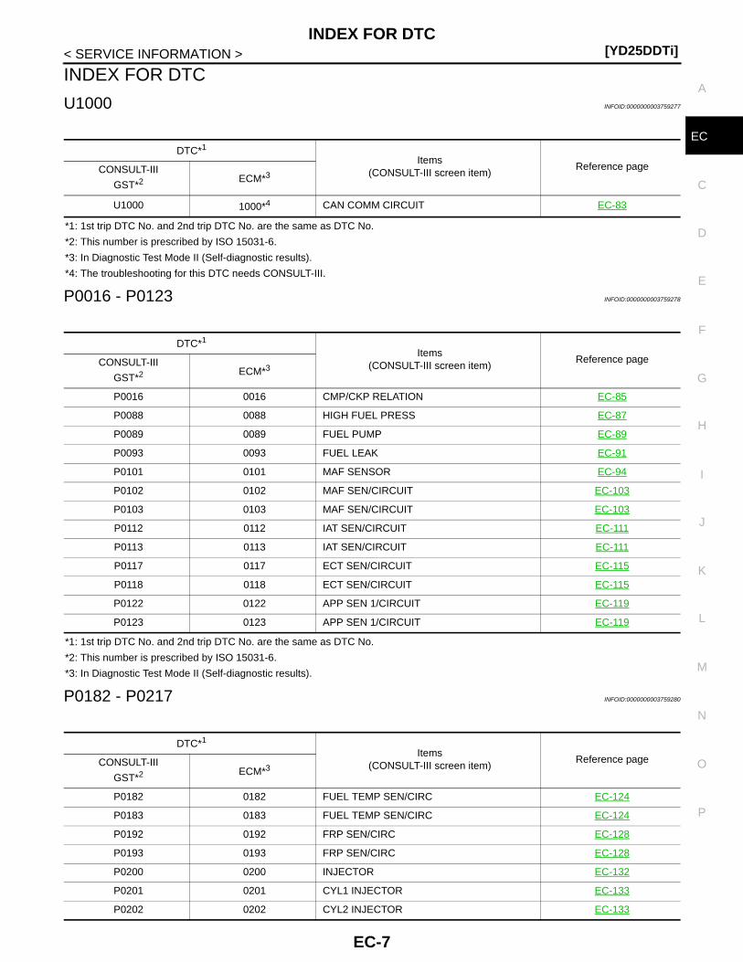
U1000 INFOID:0000000003759277
*1: 1st trip DTC No. and 2nd trip DTC No. are the same as DTC No.
*2: This number is prescribed by ISO 15031-6.
*3: In Diagnostic Test Mode II (Self-diagnostic results).
*4: The troubleshooting for this DTC needs CONSULT-III.
P0016 - P0123 INFOID:0000000003759278
*1: 1st trip DTC No. and 2nd trip DTC No. are the same as DTC No.
*2: This number is prescribed by ISO 15031-6.
*3: In Diagnostic Test Mode II (Self-diagnostic results).
P0182 - P0217 INFOID:0000000003759280
DTC*1
Items(CONSULT-III screen item)
Reference pageCONSULT-III
GST*2 ECM*3
U1000 1000*4 CAN COMM CIRCUIT EC-83
DTC*1
Items(CONSULT-III screen item)
Reference pageCONSULT-III
GST*2 ECM*3
P0016 0016 CMP/CKP RELATION EC-85
P0088 0088 HIGH FUEL PRESS EC-87
P0089 0089 FUEL PUMP EC-89
P0093 0093 FUEL LEAK EC-91
P0101 0101 MAF SENSOR EC-94
P0102 0102 MAF SEN/CIRCUIT EC-103
P0103 0103 MAF SEN/CIRCUIT EC-103
P0112 0112 IAT SEN/CIRCUIT EC-111
P0113 0113 IAT SEN/CIRCUIT EC-111
P0117 0117 ECT SEN/CIRCUIT EC-115
P0118 0118 ECT SEN/CIRCUIT EC-115
P0122 0122 APP SEN 1/CIRCUIT EC-119
P0123 0123 APP SEN 1/CIRCUIT EC-119
DTC*1
Items(CONSULT-III screen item)
Reference pageCONSULT-III
GST*2 ECM*3
P0182 0182 FUEL TEMP SEN/CIRC EC-124
P0183 0183 FUEL TEMP SEN/CIRC EC-124
P0192 0192 FRP SEN/CIRC EC-128
P0193 0193 FRP SEN/CIRC EC-128
P0200 0200 INJECTOR EC-132
P0201 0201 CYL1 INJECTOR EC-133
P0202 0202 CYL2 INJECTOR EC-133
EC-7
[YD25DDTi]INDEX FOR DTC
< SERVICE INFORMATION >
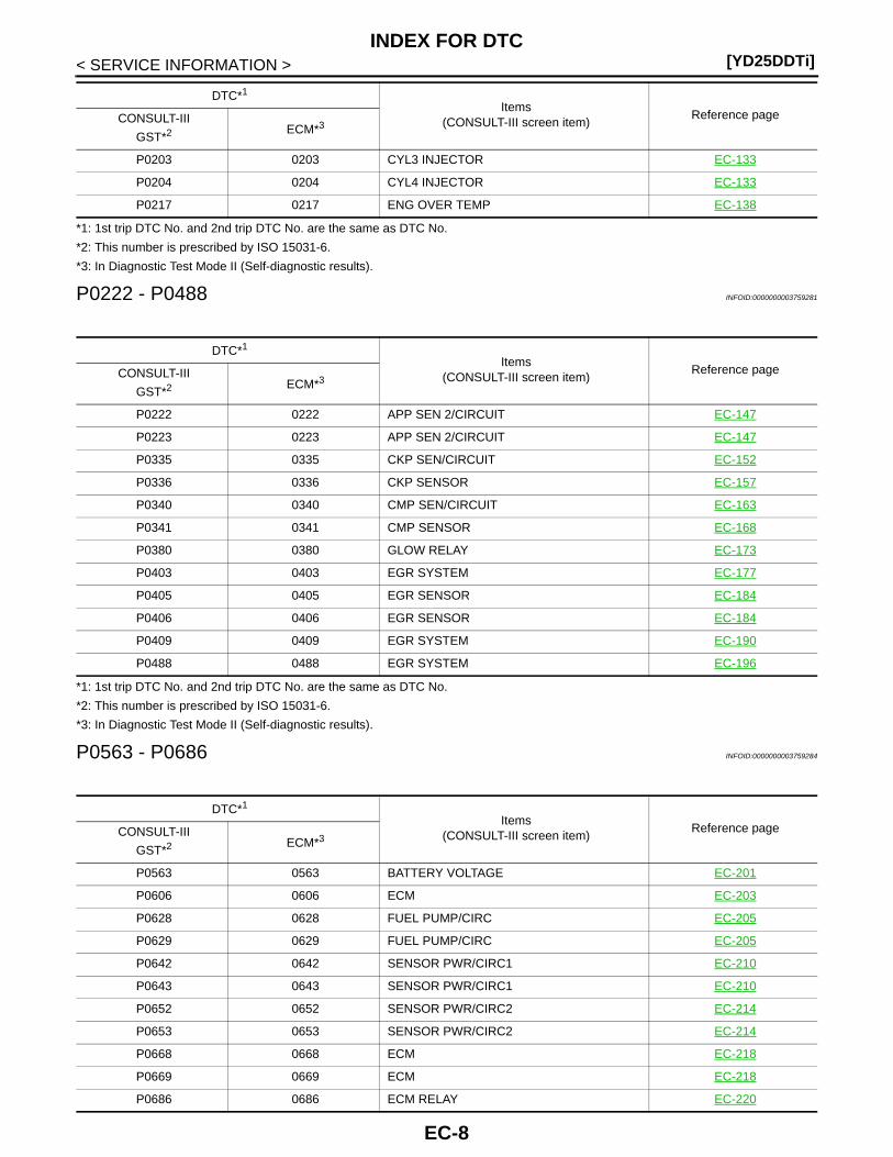
*1: 1st trip DTC No. and 2nd trip DTC No. are the same as DTC No.
*2: This number is prescribed by ISO 15031-6.
*3: In Diagnostic Test Mode II (Self-diagnostic results).
P0222 - P0488 INFOID:0000000003759281
*1: 1st trip DTC No. and 2nd trip DTC No. are the same as DTC No.
*2: This number is prescribed by ISO 15031-6.
*3: In Diagnostic Test Mode II (Self-diagnostic results).
P0563 - P0686 INFOID:0000000003759284
P0203 0203 CYL3 INJECTOR EC-133
P0204 0204 CYL4 INJECTOR EC-133
P0217 0217 ENG OVER TEMP EC-138
DTC*1
Items(CONSULT-III screen item)
Reference pageCONSULT-III
GST*2 ECM*3
DTC*1
Items(CONSULT-III screen item)
Reference pageCONSULT-III
GST*2 ECM*3
P0222 0222 APP SEN 2/CIRCUIT EC-147
P0223 0223 APP SEN 2/CIRCUIT EC-147
P0335 0335 CKP SEN/CIRCUIT EC-152
P0336 0336 CKP SENSOR EC-157
P0340 0340 CMP SEN/CIRCUIT EC-163
P0341 0341 CMP SENSOR EC-168
P0380 0380 GLOW RELAY EC-173
P0403 0403 EGR SYSTEM EC-177
P0405 0405 EGR SENSOR EC-184
P0406 0406 EGR SENSOR EC-184
P0409 0409 EGR SYSTEM EC-190
P0488 0488 EGR SYSTEM EC-196
DTC*1
Items(CONSULT-III screen item)
Reference pageCONSULT-III
GST*2 ECM*3
P0563 0563 BATTERY VOLTAGE EC-201
P0606 0606 ECM EC-203
P0628 0628 FUEL PUMP/CIRC EC-205
P0629 0629 FUEL PUMP/CIRC EC-205
P0642 0642 SENSOR PWR/CIRC1 EC-210
P0643 0643 SENSOR PWR/CIRC1 EC-210
P0652 0652 SENSOR PWR/CIRC2 EC-214
P0653 0653 SENSOR PWR/CIRC2 EC-214
P0668 0668 ECM EC-218
P0669 0669 ECM EC-218
P0686 0686 ECM RELAY EC-220
EC-8
INDEX FOR DTC[YD25DDTi]
C
D
E
F
G
H
I
J
K
L
M
A
C
N
P
O
< SERVICE INFORMATION >
E
*1: 1st trip DTC No. and 2nd trip DTC No. are the same as DTC No.
*2: This number is prescribed by ISO 15031-6.
*3: In Diagnostic Test Mode II (Self-diagnostic results).
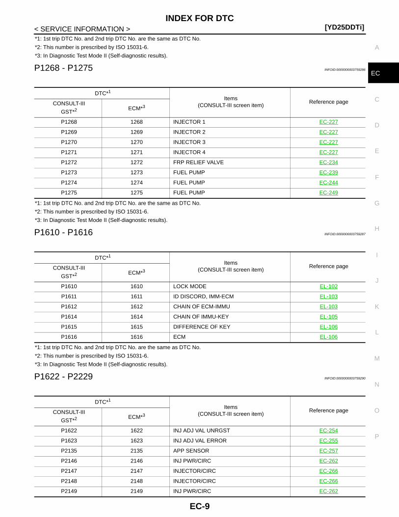
P1268 - P1275 INFOID:0000000003759286
*1: 1st trip DTC No. and 2nd trip DTC No. are the same as DTC No.
*2: This number is prescribed by ISO 15031-6.
*3: In Diagnostic Test Mode II (Self-diagnostic results).
P1610 - P1616 INFOID:0000000003759287
*1: 1st trip DTC No. and 2nd trip DTC No. are the same as DTC No.
*2: This number is prescribed by ISO 15031-6.
*3: In Diagnostic Test Mode II (Self-diagnostic results).
P1622 - P2229 INFOID:0000000003759290
DTC*1
Items(CONSULT-III screen item)
Reference pageCONSULT-III
GST*2 ECM*3
P1268 1268 INJECTOR 1 EC-227
P1269 1269 INJECTOR 2 EC-227
P1270 1270 INJECTOR 3 EC-227
P1271 1271 INJECTOR 4 EC-227
P1272 1272 FRP RELIEF VALVE EC-234
P1273 1273 FUEL PUMP EC-239
P1274 1274 FUEL PUMP EC-244
P1275 1275 FUEL PUMP EC-249
DTC*1
Items(CONSULT-III screen item)
Reference pageCONSULT-III
GST*2 ECM*3
P1610 1610 LOCK MODE EL-102
P1611 1611 ID DISCORD, IMM-ECM EL-103
P1612 1612 CHAIN OF ECM-IMMU EL-103
P1614 1614 CHAIN OF IMMU-KEY EL-105
P1615 1615 DIFFERENCE OF KEY EL-106
P1616 1616 ECM EL-106
DTC*1
Items(CONSULT-III screen item)
Reference pageCONSULT-III
GST*2 ECM*3
P1622 1622 INJ ADJ VAL UNRGST EC-254
P1623 1623 INJ ADJ VAL ERROR EC-255
P2135 2135 APP SENSOR EC-257
P2146 2146 INJ PWR/CIRC EC-262
P2147 2147 INJECTOR/CIRC EC-266
P2148 2148 INJECTOR/CIRC EC-266
P2149 2149 INJ PWR/CIRC EC-262
EC-9
[YD25DDTi]INDEX FOR DTC
< SERVICE INFORMATION >
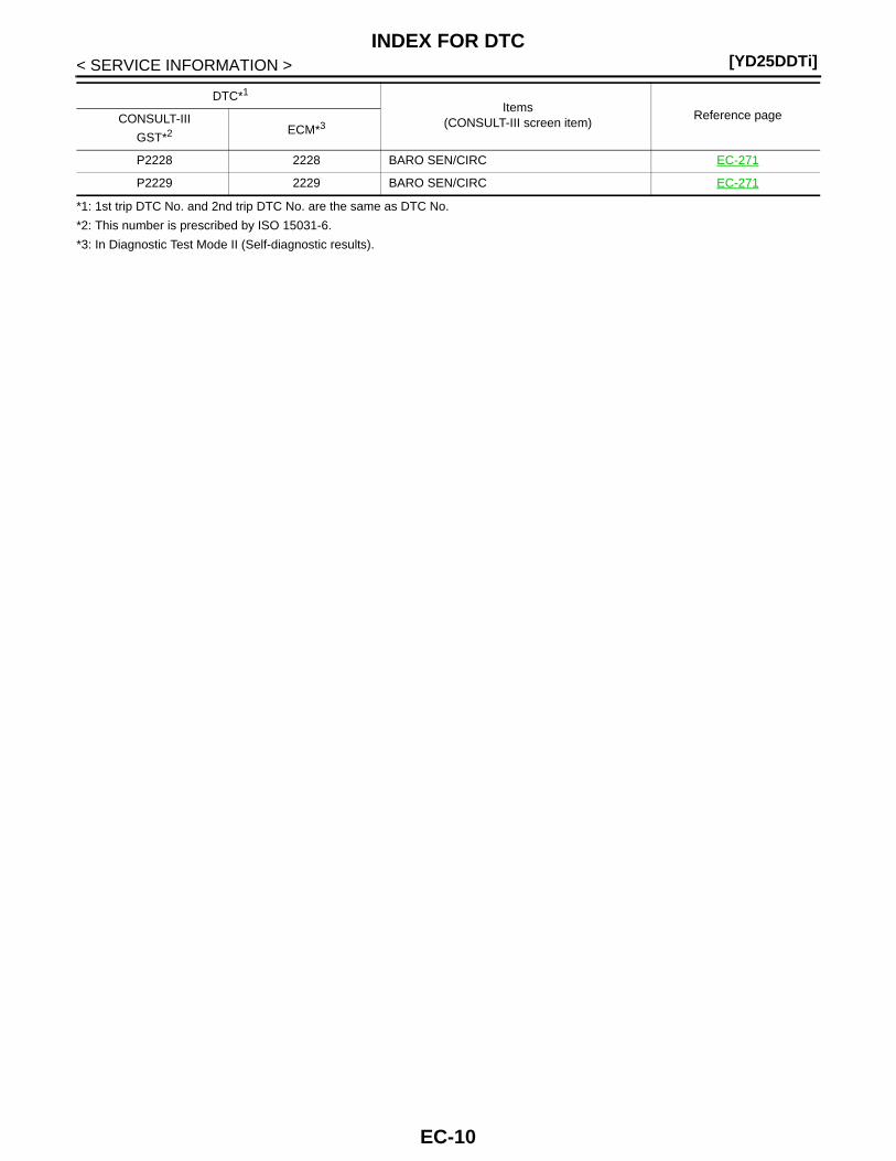
*1: 1st trip DTC No. and 2nd trip DTC No. are the same as DTC No.
*2: This number is prescribed by ISO 15031-6.
*3: In Diagnostic Test Mode II (Self-diagnostic results).
P2228 2228 BARO SEN/CIRC EC-271
P2229 2229 BARO SEN/CIRC EC-271
DTC*1
Items(CONSULT-III screen item)
Reference pageCONSULT-III
GST*2 ECM*3
EC-10
PRECAUTIONS[YD25DDTi]
C
D
E
F
G
H
I
J
K
L
M
A
C
N
P
O
< SERVICE INFORMATION >
E
PRECAUTIONS
Precaution for Supplemental Restraint System (SRS) "AIR BAG" and "SEAT BELT PRE-TENSIONER" INFOID:0000000003761794
The Supplemental Restraint System such as “AIR BAG” and “SEAT BELT PRE-TENSIONER”, used alongwith a front seat belt, helps to reduce the risk or severity of injury to the driver and front passenger for certaintypes of collision. Information necessary to service the system safely is included in the “SUPPLEMENTALRESTRAINT SYSTEM” and “SEAT BELTS” of this Service Manual.WARNING:• To avoid rendering the SRS inoperative, which could increase the risk of personal injury or death in
the event of a collision which would result in air bag inflation, all maintenance must be performed byan authorized NISSAN/INFINITI dealer.
• Improper maintenance, including incorrect removal and installation of the SRS, can lead to personalinjury caused by unintentional activation of the system. For removal of Spiral Cable and Air BagModule, see the “SUPPLEMENTAL RESTRAINT SYSTEM”.
• Do not use electrical test equipment on any circuit related to the SRS unless instructed to in thisService Manual. SRS wiring harnesses can be identified by yellow and/or orange harnesses or har-ness connectors.
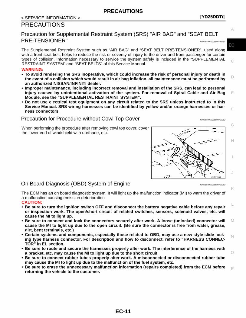
Precaution for Procedure without Cowl Top Cover INFOID:0000000003759292
When performing the procedure after removing cowl top cover, coverthe lower end of windshield with urethane, etc.
On Board Diagnosis (OBD) System of Engine INFOID:0000000003759293
The ECM has an on board diagnostic system. It will light up the malfunction indicator (MI) to warn the driver ofa malfunction causing emission deterioration.CAUTION:• Be sure to turn the ignition switch OFF and disconnect the battery negative cable before any repair
or inspection work. The open/short circuit of related switches, sensors, solenoid valves, etc. willcause the MI to light up.
• Be sure to connect and lock the connectors securely after work. A loose (unlocked) connector willcause the MI to light up due to the open circuit. (Be sure the connector is free from water, grease,dirt, bent terminals, etc.)
• Certain systems and components, especially those related to OBD, may use a new style slide-lock-ing type harness connector. For description and how to disconnect, refer to “HARNESS CONNEC-TOR” in EL section.
• Be sure to route and secure the harnesses properly after work. The interference of the harness witha bracket, etc. may cause the MI to light up due to the short circuit.
• Be sure to connect rubber tubes properly after work. A misconnected or disconnected rubber tubemay cause the MI to light up due to the malfunction of the fuel system, etc.
• Be sure to erase the unnecessary malfunction information (repairs completed) from the ECM beforereturning the vehicle to the customer.
PIIB3706J
EC-11

[YD25DDTi]PRECAUTIONS
< SERVICE INFORMATION >
Precaution INFOID:0000000003759294
• Always use a 12 volt battery as power source.• Do not attempt to disconnect battery cables while engine is
running.• Before connecting or disconnecting the ECM harness con-
nector, turn ignition switch OFF and disconnect battery nega-tive cable. Failure to do so may damage the ECM becausebattery voltage is applied to ECM even if ignition switch isturned OFF.
• Before removing parts, turn ignition switch OFF and then dis-connect battery negative cable.
• Do not disassemble ECM.
• When connecting ECM harness connector, fasten it securelywith levers as far as they will go as shown in the figure.
• When connecting or disconnecting pin connectors into orfrom ECM, take care not to damage pin terminals (bend orbreak).Make sure that there are not any bends or breaks on ECM pinterminal, when connecting pin connectors.
• Securely connect ECM harness connectors.A poor connection can cause an extremely high (surge) volt-age to develop in coil and condenser, thus resulting in dam-age to IC's.
• Keep engine control system harness at least 10cm (4 in) awayfrom adjacent harness, to prevent engine control system mal-functions due to receiving external noise, degraded operationof IC's, etc.
• Keep engine control system parts and harness dry.
SEF289H
MBIB0625E
PBIB1512E
SEF291H
EC-12
PRECAUTIONS[YD25DDTi]
C
D
E
F
G
H
I
J
K
L
M
A
C
N
P
O
< SERVICE INFORMATION >
E
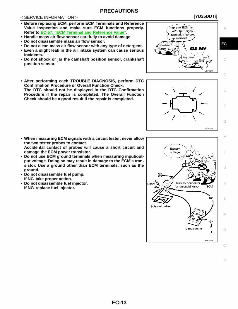
• Before replacing ECM, perform ECM Terminals and ReferenceValue inspection and make sure ECM functions properly.Refer to EC-57, "ECM Terminal and Reference Value".
• Handle mass air flow sensor carefully to avoid damage.• Do not disassemble mass air flow sensor.• Do not clean mass air flow sensor with any type of detergent.• Even a slight leak in the air intake system can cause serious
incidents.• Do not shock or jar the camshaft position sensor, crankshaft
position sensor.
• After performing each TROUBLE DIAGNOSIS, perform DTCConfirmation Procedure or Overall Function Check.The DTC should not be displayed in the DTC ConfirmationProcedure if the repair is completed. The Overall FunctionCheck should be a good result if the repair is completed.
• When measuring ECM signals with a circuit tester, never allowthe two tester probes to contact.Accidental contact of probes will cause a short circuit anddamage the ECM power transistor.
• Do not use ECM ground terminals when measuring input/out-put voltage. Doing so may result in damage to the ECM's tran-sistor. Use a ground other than ECM terminals, such as theground.
• Do not disassemble fuel pump.If NG, take proper action.
• Do not disassemble fuel injector.If NG, replace fuel injector.
MEF040D
SAT652J
SEF348N
EC-13

[YD25DDTi]PRECAUTIONS
< SERVICE INFORMATION >• Do not depress accelerator pedal when starting.• Immediately after starting, do not rev up engine unnecessar-
ily.• Do not rev up engine just prior to shutdown.
• When installing C.B. ham radio or a mobile phone, be sure toobserve the following as it may adversely affect electroniccontrol systems depending on installation location.
- Keep the antenna as far as possible from the electronic con-trol units.
- Keep the antenna feeder line more than 20 cm (8 in) awayfrom the harness of electronic controls.Do not let them run parallel for a long distance.
- Adjust the antenna and feeder line so that the standing-waveradio can be kept smaller.
- Be sure to ground the radio to vehicle body.
SEF709Y
SEF708Y
EC-14

PREPARATION[YD25DDTi]
C
D
E
F
G
H
I
J
K
L
M
A
C
N
P
O
< SERVICE INFORMATION >
E
PREPARATION
Special Service Tool INFOID:0000000003759295
Tool numberTool name
Description
EG17650301Radiator cap tester adapter
Adapting radiator cap tester to radiator cap and ra-diator filler necka: 28 (1.10) dia.b: 31.4 (1.236) dia.c: 41.3 (1.626) dia.Unit: mm (in)
KV11106030Positioning stopper pin
Fixing fuel pump sprocketa: 6 mm (0.24 in) dia.b: 80 mm (3.15 in) dia.
KV11106040TORX wrench
Removing and installing fuel pump sprocketa: T70b: 26 mm (1.02 in)
KV11106050Hexagonal wrench
Removing and installing fuel pump sprocketa: 6 mm (0.24 in) (Face to face)b: 42 mm (1.65 in)
KV11106060Sprocket holder
Holding fuel pump sprocket
S-NT564
NT804
NT805
SBIA0224E
SBIA0225E
EC-15
[YD25DDTi]PREPARATION
< SERVICE INFORMATION >
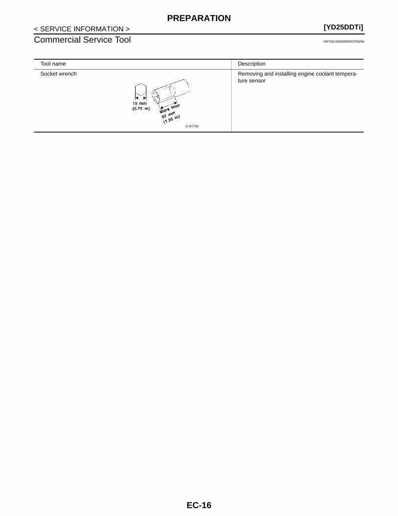
Commercial Service Tool INFOID:0000000003759296
Tool name Description
Socket wrench Removing and installing engine coolant tempera-ture sensor
S-NT705
EC-16
ENGINE CONTROL SYSTEM[YD25DDTi]
C
D
E
F
G
H
I
J
K
L
M
A
C
N
P
O
< SERVICE INFORMATION >
E
ENGINE CONTROL SYSTEM
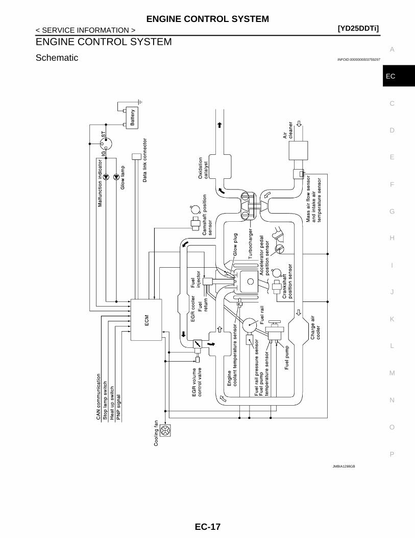
Schematic INFOID:0000000003759297
JMBIA1298GB
EC-17

[YD25DDTi]ENGINE CONTROL SYSTEM
< SERVICE INFORMATION >
System Chart INFOID:0000000003759299
*1: The input signal is sent to the ECM through CAN communication line.
*2: The output signal is sent from the ECM through CAN communication line.
Fuel Injection Control System INFOID:0000000003759300
SYSTEM DESCRIPTIONThree types of fuel injection control are provided to accommodate engine operating conditions; normal control,idle control and start control. The ECM determines the appropriate fuel injection control. Under each control,the amount of fuel injected is adjusted to improve engine performance.Pulse signals are sent to fuel injectors according to the input signals to adjust the amount of fuel injected topreset value.
START CONTROL
Input/Output Signal Chart
When the ECM receives a start signal from the ignition switch, theECM adapts the fuel injection system for the start control. Theamount of fuel injected at engine starting is a preset program valuein the ECM. The program is determined by the engine speed, enginecoolant temperature and fuel rail pressure.For better start ability under cool engine conditions, the lower thecoolant temperature becomes, the greater the amount of fuelinjected. The ECM ends the start control when the engine speedreaches the specific value, and shifts the control to the normal or idlecontrol.
IDLE CONTROL
Input/Output Signal Chart
Input (Sensor) ECM Function Output (Actuator)
• Accelerator pedal position sensor• Fuel rail pressure sensor• Fuel pump temperature sensor• Engine coolant temperature sensor• Mass air flow sensor• Intake air temperature sensor• Crankshaft position sensor• Camshaft position sensor
• Vehicle speed sensor*1
• ABS actuator and electric unit (control unit)*1
• Ignition switch• Stop lamp switch
• Air conditioner switch*1
• Park/neutral position switch• Battery voltage• EGR volume control valve control position
sensor
Fuel injection control• Fuel injector• Fuel pump
Fuel injection timing control• Fuel injector• Fuel pump
Fuel cut control• Fuel injector• Fuel pump
Glow control system• Glow relay
• Glow indicator lamp*2
On board diagnostic system Malfunction indicator (MI)*2
EGR volume control EGR volume control valve
Cooling fan control Cooling fan relay
Sensor Input Signal to ECM ECM Function Actuator
Engine coolant temperature sensor Engine coolant temperature
Fuel injection control (start control)
Fuel injectorFuel pump
Crankshaft position sensor Engine speed
Camshaft position sensor Piston position
Ignition switch Start signal
Fuel rail pressure sensor Fuel rail pressure
SEF648S
EC-18

ENGINE CONTROL SYSTEM[YD25DDTi]
C
D
E
F
G
H
I
J
K
L
M
A
C
N
P
O
< SERVICE INFORMATION >
E
*: The input signal is sent to the ECM through CAN communication line.
When the ECM determines that the engine speed is at idle, the fuel injection system is adapted for the idlecontrol. The ECM regulates the amount of fuel injected corresponding to changes in load applied to the engineto keep engine speed constant. The ECM also provides the system with a fast idle control in response to theengine coolant temperature signal.
NORMAL CONTROL
Input/Output Signal Chart
The amount of fuel injected under normal driving conditions is deter-mined according to sensor signals. The crankshaft position sensordetects engine speed, the accelerator pedal position sensor detectsaccelerator pedal position and fuel rail pressure sensor detects fuelrail pressure. These sensors send signals to the ECM.The fuel injection data, predetermined by correlation between vari-ous engine speeds, accelerator pedal positions and fuel rail pres-sure are stored in the ECM memory, forming a map. The ECMdetermines the optimal amount of fuel to be injected using the sen-sor signals in comparison with the map.
MAXIMUM AMOUNT CONTROL
Input/Output Signal Chart
The maximum injection amount is controlled to an optimum by the engine speed, intake air amount, enginecoolant temperature, and accelerator opening in accordance with the driving conditions.This prevents the oversupply of the injection amount caused by decreased air density at a high altitude or dur-ing a system failure.
DECELERATION CONTROL
Input/Output Signal Chart
Sensor Input Signal to ECM ECM Function Actuator
Engine coolant temperature sensor Engine coolant temperature
Fuel injection control (Idle control)
Fuel injectorFuel pump
Crankshaft position sensor Engine speed
Battery Battery voltage
Accelerator pedal position sensor Accelerator pedal position
Fuel rail pressure sensor Fuel rail pressure
Vehicle speed sensor Vehicle speed*
Air conditioner switch Air conditioner signal*
Sensor Input Signal to ECM ECM Function Actuator
Crankshaft position sensor Engine speedFuel injection control (Normal control)
Fuel injectorFuel pump
Accelerator pedal position sensor Accelerator position
Fuel rail pressure sensor Fuel rail pressure
SEF649S
Sensor Input Signal to ECM ECM Function Actuator
Mass air flow sensor Amount of intake airFuel injection control (Maxi-mum amount control)
Fuel InjectorEngine coolant temperature sensor Engine coolant temperature
Crankshaft position sensor Engine speed
Accelerator pedal position sensor Accelerator pedal position
EC-19
[YD25DDTi]ENGINE CONTROL SYSTEM
< SERVICE INFORMATION >
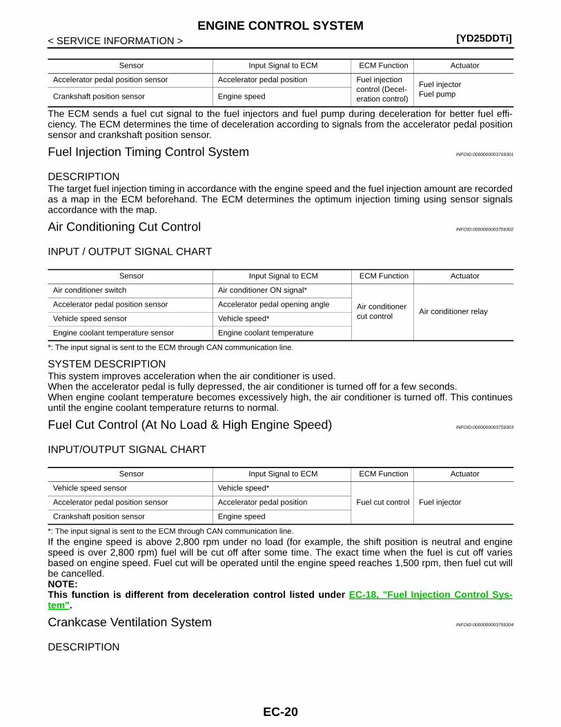
The ECM sends a fuel cut signal to the fuel injectors and fuel pump during deceleration for better fuel effi-ciency. The ECM determines the time of deceleration according to signals from the accelerator pedal positionsensor and crankshaft position sensor.
Fuel Injection Timing Control System INFOID:0000000003759301
DESCRIPTIONThe target fuel injection timing in accordance with the engine speed and the fuel injection amount are recordedas a map in the ECM beforehand. The ECM determines the optimum injection timing using sensor signalsaccordance with the map.
Air Conditioning Cut Control INFOID:0000000003759302
INPUT / OUTPUT SIGNAL CHART
*: The input signal is sent to the ECM through CAN communication line.
SYSTEM DESCRIPTIONThis system improves acceleration when the air conditioner is used.When the accelerator pedal is fully depressed, the air conditioner is turned off for a few seconds.When engine coolant temperature becomes excessively high, the air conditioner is turned off. This continuesuntil the engine coolant temperature returns to normal.
Fuel Cut Control (At No Load & High Engine Speed) INFOID:0000000003759303
INPUT/OUTPUT SIGNAL CHART
*: The input signal is sent to the ECM through CAN communication line.
If the engine speed is above 2,800 rpm under no load (for example, the shift position is neutral and enginespeed is over 2,800 rpm) fuel will be cut off after some time. The exact time when the fuel is cut off variesbased on engine speed. Fuel cut will be operated until the engine speed reaches 1,500 rpm, then fuel cut willbe cancelled.NOTE:This function is different from deceleration control listed under EC-18, "Fuel Injection Control Sys-tem".
Crankcase Ventilation System INFOID:0000000003759304
DESCRIPTION
Sensor Input Signal to ECM ECM Function Actuator
Accelerator pedal position sensor Accelerator pedal position Fuel injection control (Decel-eration control)
Fuel injectorFuel pumpCrankshaft position sensor Engine speed
Sensor Input Signal to ECM ECM Function Actuator
Air conditioner switch Air conditioner ON signal*
Air conditioner cut control
Air conditioner relayAccelerator pedal position sensor Accelerator pedal opening angle
Vehicle speed sensor Vehicle speed*
Engine coolant temperature sensor Engine coolant temperature
Sensor Input Signal to ECM ECM Function Actuator
Vehicle speed sensor Vehicle speed*
Fuel cut control Fuel injectorAccelerator pedal position sensor Accelerator pedal position
Crankshaft position sensor Engine speed
EC-20
ENGINE CONTROL SYSTEM[YD25DDTi]
C
D
E
F
G
H
I
J
K
L
M
A
C
N
P
O
< SERVICE INFORMATION >
E
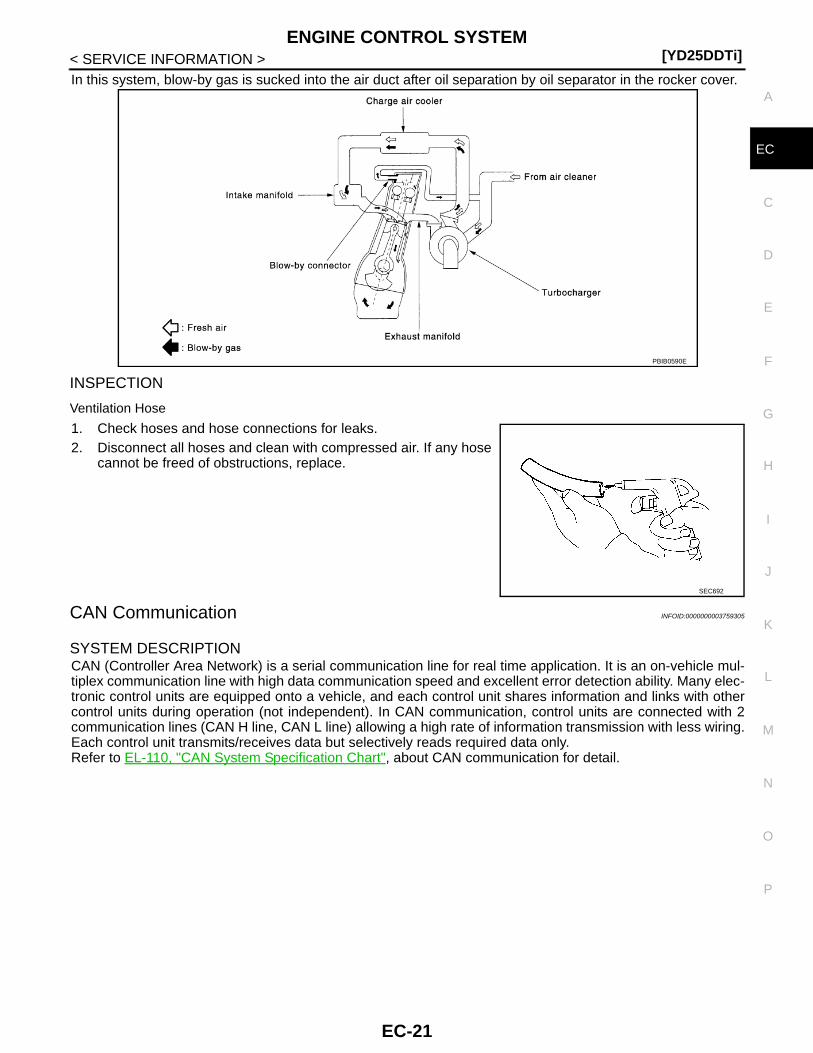
In this system, blow-by gas is sucked into the air duct after oil separation by oil separator in the rocker cover.
INSPECTION
Ventilation Hose
1. Check hoses and hose connections for leaks.2. Disconnect all hoses and clean with compressed air. If any hose
cannot be freed of obstructions, replace.
CAN Communication INFOID:0000000003759305
SYSTEM DESCRIPTIONCAN (Controller Area Network) is a serial communication line for real time application. It is an on-vehicle mul-tiplex communication line with high data communication speed and excellent error detection ability. Many elec-tronic control units are equipped onto a vehicle, and each control unit shares information and links with othercontrol units during operation (not independent). In CAN communication, control units are connected with 2communication lines (CAN H line, CAN L line) allowing a high rate of information transmission with less wiring.Each control unit transmits/receives data but selectively reads required data only.Refer to EL-110, "CAN System Specification Chart", about CAN communication for detail.
PBIB0590E
SEC692
EC-21

[YD25DDTi]BASIC SERVICE PROCEDURE
< SERVICE INFORMATION >
BASIC SERVICE PROCEDURE
Fuel Filter INFOID:0000000003843895
DESCRIPTIONA water draining cock is on the lower side and a priming pump for bleeding air is on the upper side.
AIR BLEEDINGPump the priming pump (1) to bleed air.• When air is bled completely, the pumping of the priming pump sud-
denly becomes heavy. Stop the operation at that time.• If it is difficult to bleed air by the pumping of the priming pump (the
pumping of the priming pump does not become heavy), disconnectthe fuel supply hose between the fuel filter and the fuel gallery.Then, perform the operation described above, and make sure thatfuel comes out. (Use a pan, etc. so as not to spill fuel. Do not letfuel get on engine and other parts.) After that, connect the hose,then bleed air again.
• Start engine and let it idle for at least 1 minute after performing airbleeding.
WATER DRAINING1. Remove the fuel filter, filter bracket, protector assembly from the dash panel as follows.a. Remove the air cleaner case (upper), air duct assembly, and vacuum hose for brake booster (between the
vacuum pump and vacuum pipe).CAUTION:After the duct is removed, cover the opening with gum tape, etc. to prevent foreign object fromgetting into the engine during the operation.
b. Remove the mounting nuts on the dash panel, then remove the fuel filter, filter bracket, and protectorassembly from the dash panel.• It is not necessary to disconnect the fuel hose.
2. Using a tool such as a pliers, loosen the water draining cock atthe bottom of the fuel filter.Loosening drain cock four to five turns causes water tostart draining.Do not remove drain cock by loosening it excessively.If water dose not drain properly, move the priming up and down.CAUTION:When the water is drained, the fuel is also drained. Use apan, etc. to avoid fuel adherence to the rubber parts such asthe engine mount insulator.Do not over-tighten the water draining cock. This will dam-age the cock thread, resulting in water or fuel leak.
3. Bleed air of the fuel filter. Refer to “AIR BLEEDING”.4. Start the engine.
Procedure After Replacing ECM INFOID:0000000003759307
When replacing ECM, the following procedure must be performed.1. Perform initialization of NATS system and registration of all NATS ignition key IDs. Refer to EL-96, "ECM
Re-communicating Function".2. Perform EC-22, "Injector Adjustment Value Registration".3. Perform EC-23, "Fuel Pump Learning Value Clearing".4. Perform EC-24, "EGR Volume Control Valve Closed Position Learning Value Clear".5. Perform EC-24, "EGR Volume Control Valve Closed Position Learning".
Injector Adjustment Value Registration INFOID:0000000003759308
DESCRIPTION
JMBIA1280ZZ
SMA825B
EC-22
BASIC SERVICE PROCEDURE[YD25DDTi]
C
D
E
F
G
H
I
J
K
L
M
A
C
N
P
O
< SERVICE INFORMATION >
E
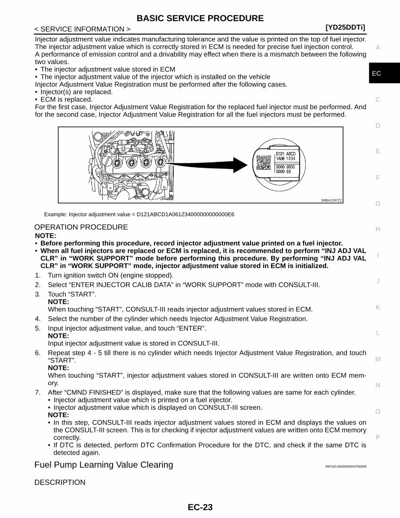
Injector adjustment value indicates manufacturing tolerance and the value is printed on the top of fuel injector.The injector adjustment value which is correctly stored in ECM is needed for precise fuel injection control.A performance of emission control and a drivability may effect when there is a mismatch between the followingtwo values.• The injector adjustment value stored in ECM• The injector adjustment value of the injector which is installed on the vehicleInjector Adjustment Value Registration must be performed after the following cases.• Injector(s) are replaced.• ECM is replaced.For the first case, Injector Adjustment Value Registration for the replaced fuel injector must be performed. Andfor the second case, Injector Adjustment Value Registration for all the fuel injectors must be performed.
OPERATION PROCEDURENOTE:• Before performing this procedure, record injector adjustment value printed on a fuel injector.• When all fuel injectors are replaced or ECM is replaced, it is recommended to perform “INJ ADJ VAL
CLR” in “WORK SUPPORT” mode before performing this procedure. By performing “INJ ADJ VALCLR” in “WORK SUPPORT” mode, injector adjustment value stored in ECM is initialized.
1. Turn ignition switch ON (engine stopped).2. Select “ENTER INJECTOR CALIB DATA” in “WORK SUPPORT” mode with CONSULT-III.3. Touch “START”.
NOTE:When touching “START”, CONSULT-III reads injector adjustment values stored in ECM.
4. Select the number of the cylinder which needs Injector Adjustment Value Registration.5. Input injector adjustment value, and touch “ENTER”.
NOTE:Input injector adjustment value is stored in CONSULT-III.
6. Repeat step 4 - 5 till there is no cylinder which needs Injector Adjustment Value Registration, and touch“START”.NOTE:When touching “START”, injector adjustment values stored in CONSULT-III are written onto ECM mem-ory.
7. After “CMND FINISHED” is displayed, make sure that the following values are same for each cylinder.• Injector adjustment value which is printed on a fuel injector.• Injector adjustment value which is displayed on CONSULT-III screen.NOTE:• In this step, CONSULT-III reads injector adjustment values stored in ECM and displays the values on
the CONSULT-III screen. This is for checking if injector adjustment values are written onto ECM memorycorrectly.
• If DTC is detected, perform DTC Confirmation Procedure for the DTC, and check if the same DTC isdetected again.
Fuel Pump Learning Value Clearing INFOID:0000000003759309
DESCRIPTION
Example: Injector adjustment value = D121ABCD1A061234000000000000E6
JMBIA1297ZZ
EC-23

[YD25DDTi]BASIC SERVICE PROCEDURE
< SERVICE INFORMATION >In order to always keep optimum fuel pressure in fuel rail, the ECM controls fuel pump in high precision withmonitoring the signal of fuel rail pressure sensor.Accordingly, the ECM always learns characteristic value of fuel pump. Fuel Pump Learning Value Clearing isan operation to clear the value of the fuel pump learning.Fuel Pump Learning Value Clearing should be performed under the following conditions.• Fuel pump is changed.• ECM is replaced with used one which stores the fuel pump learning value of other fuel pump.
OPERATION PROCEDURENOTE:When removing fuel pump, perform Fuel Pump Learning Value Clearing before starting engine.
With CONSULT-III
1. Turn ignition switch ON.2. Select “PUMP LEARNT CLEAR” in “ACTIVE TEST” mode with CONSULT-III.3. Touch “CLEAR” and wait a few seconds.4. Make sure that “CMPLT” is displayed on CONSULT-III screen.
Without CONSULT-IIIFuel pump learning value can be erased from the back up memory in the ECM by the same operation as eras-ing DTC. In detail, refer to EC-32, "Emission-Related Diagnostic Information".
EGR Volume Control Valve Closed Position Learning Value Clear INFOID:0000000003759310
EGR volume control valve closed position learning value should be cleared under the following cases.• EGR volume control valve is removed.• EGR volume control valve is replaced.
OPERATION PROCEDURENOTE:Always perform the following procedure with engine coolant temperature 0 to 30°C (32 to 86°F).1. Turn ignition switch ON.2. Select “EGR/V LEARN CLR” in “WORK SUPPORT” mode with CONSULT-III.3. Touch “CLEAR” and wait a few seconds.4. Make sure the “CMPLT” is displayed on CONSULT-III screen.
EGR Volume Control Valve Closed Position Learning INFOID:0000000003759311
EGR Volume Control Valve Closed Position Learning is an operation to learn the fully closed position of theEGR volume control valve by monitoring the EGR volume control valve control position sensor output signal. Itmust be performed under any of the following conditions:• EGR volume control valve is replaced.• ECM is replaced.
OPERATION PROCEDURE1. Turn ignition switch ON and wait at least 10 seconds.2. Turn ignition switch OFF and wait at least 10 seconds.
Make sure that EGR volume control valve moves during above 10 seconds by confirming the operatingsound.
FUEL PUMP INFOID:0000000003844070
Components
EC-24

BASIC SERVICE PROCEDURE[YD25DDTi]
C
D
E
F
G
H
I
J
K
L
M
A
C
N
P
O
< SERVICE INFORMATION >
E
• Refer to “HOW TO USE THIS MANUAL” in GI section for symbol marks in the figure.
Removal and InstallationCAUTION:• Before removing and installing fuel pump, be sure to remove sprocket. Never loosen or remove
installation nut in the center of fuel pump. If loosened or removed, replace fuel pump.• After removing timing chain, never turn crankshaft and camshaft separately, or valves will strike pis-
ton heads.• When installing camshafts, chain tensioners, oil seals, or other sliding parts, lubricate contacting
surfaces with new engine oil.• When fuel pump is replaced with new one or another one, perform fuel pump leaning value cleaning
before starting engine. Refer to EC-23, "Fuel Pump Learning Value Clearing".
REMOVAL1. Remove engine cover, vacuum gallery and heater feed pipe. Refer to EM-6.2. Remove fuel hose and spill hose from fuel pump. Refer to EM-8.
CAUTION:Be careful not to spill fuel in the engine component.
3. Disconnect harness connectors from fuel pump.4. Remove injection tube center, clip and insert rubber. Refer to EM-8.
CAUTION:Be careful not to spill fuel in the engine component.
1. Washer 2. Fuel pump sprocket 3. Seal washer
4. O-ring 5. Adjusting shim 6. Sprocket nut
7. Coupling 8. Oil seal 9. Spacer
10. Key 11. Fuel pump 12. Fuel hose
13. Spill hose
: Engine front
PBIC3438E
EC-25

[YD25DDTi]BASIC SERVICE PROCEDURE
< SERVICE INFORMATION >
5. Remove secondary timing chain. Refer to “TIMING CHAIN” in EM section.6. Hold fuel pump sprocket and remove bolt.a. Insert the positioning stopper pin [SST (KV11106030)] into the
hole 6 mm (0.24 in) in the diameter on the fuel pump sprocket.b. Using the TORX wrench [SST (KV11106040)], turn pump shaft
little by little to adjust the position of fuel pump sprocket so thatthe holes align.
c. Push the positioning stopper pin [SST (KV11106030)] throughfuel pump sprocket to fuel pump body to hold fuel pumpsprocket.
• Insert the positioning stopper pin until its flange contacts the fuelpump sprocket.
7. Using the hexagonal wrench [SST (KV11106050)] remove tight-ening bolts of fuel pump sprocket.
MBIA0049E
PBIC2535E
PBIC2404E
MBIA0074E
EC-26
BASIC SERVICE PROCEDURE[YD25DDTi]
C
D
E
F
G
H
I
J
K
L
M
A
C
N
P
O
< SERVICE INFORMATION >
E
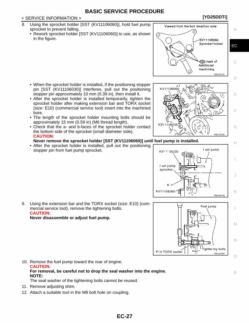
8. Using the sprocket holder [SST (KV11106060)], hold fuel pumpsprocket to prevent falling.• Rework sprocket holder [SST (KV11106060)] to use, as shown
in the figure.
• When the sprocket holder is installed, if the positioning stopperpin [SST (KV11106030)] interferes, pull out the positioningstopper pin approximately 10 mm (0.39 in), then install it.
• After the sprocket holder is installed temporarily, tighten thesprocket holder after making extension bar and TORX socket(size: E10) (commercial service tool) insert into the machinedbore.
• The length of the sprocket holder mounting bolts should beapproximately 15 mm (0.59 in) (M6 thread length).
• Check that the a- and b-faces of the sprocket holder contactthe bottom side of the sprocket (small diameter side).CAUTION:Never remove the sprocket holder [SST (KV11106060)] until fuel pump is installed.
• After the sprocket holder is installed, pull out the positioningstopper pin from fuel pump sprocket.
9. Using the extension bar and the TORX socket (size: E10) (com-mercial service tool), remove the tightening bolts.CAUTION:Never disassemble or adjust fuel pump.
10. Remove the fuel pump toward the rear of engine.CAUTION:For removal, be careful not to drop the seal washer into the engine.NOTE:The seal washer of the tightening bolts cannot be reused.
11. Remove adjusting shim.12. Attach a suitable tool in the M8 bolt hole on coupling.
SBIA0217E
PBIC2534E
MBIA0075E
PBIC2405E
EC-27

[YD25DDTi]BASIC SERVICE PROCEDURE
< SERVICE INFORMATION >13. Loosen sprocket nut with the TORX wrench [SST
(KV11106040)].
14. Remove coupling with a suitable puller.
15. Remove spacer from fuel pump.16. Remove oil seal from spacer.
INSPECTION AFTER REMOVAL
Timing ChainCheck for cracks and excessive wear at roller links. Replacetiming chain if necessary.
INSTALLATION1. Install new oil seal to spacer.
2. Install spacer to fuel pump.
MBIA0013E
MBIA0014E
SEM984C
MBIA0045E
EC-28
BASIC SERVICE PROCEDURE[YD25DDTi]
C
D
E
F
G
H
I
J
K
L
M
A
C
N
P
O
< SERVICE INFORMATION >
E
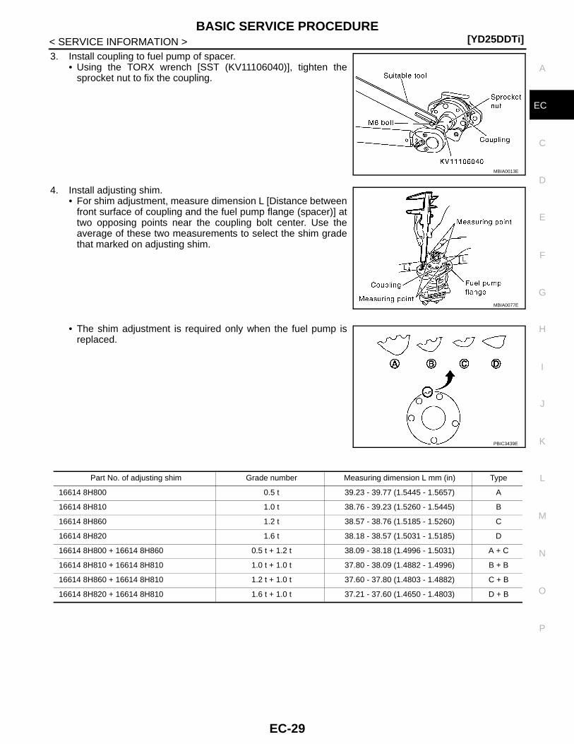
3. Install coupling to fuel pump of spacer.• Using the TORX wrench [SST (KV11106040)], tighten the
sprocket nut to fix the coupling.
4. Install adjusting shim.• For shim adjustment, measure dimension L [Distance between
front surface of coupling and the fuel pump flange (spacer)] attwo opposing points near the coupling bolt center. Use theaverage of these two measurements to select the shim gradethat marked on adjusting shim.
• The shim adjustment is required only when the fuel pump isreplaced.
MBIA0013E
MBIA0077E
PBIC3439E
Part No. of adjusting shim Grade number Measuring dimension L mm (in) Type
16614 8H800 0.5 t 39.23 - 39.77 (1.5445 - 1.5657) A
16614 8H810 1.0 t 38.76 - 39.23 (1.5260 - 1.5445) B
16614 8H860 1.2 t 38.57 - 38.76 (1.5185 - 1.5260) C
16614 8H820 1.6 t 38.18 - 38.57 (1.5031 - 1.5185) D
16614 8H800 + 16614 8H860 0.5 t + 1.2 t 38.09 - 38.18 (1.4996 - 1.5031) A + C
16614 8H810 + 16614 8H810 1.0 t + 1.0 t 37.80 - 38.09 (1.4882 - 1.4996) B + B
16614 8H860 + 16614 8H810 1.2 t + 1.0 t 37.60 - 37.80 (1.4803 - 1.4882) C + B
16614 8H820 + 16614 8H810 1.6 t + 1.0 t 37.21 - 37.60 (1.4650 - 1.4803) D + B
EC-29
[YD25DDTi]BASIC SERVICE PROCEDURE
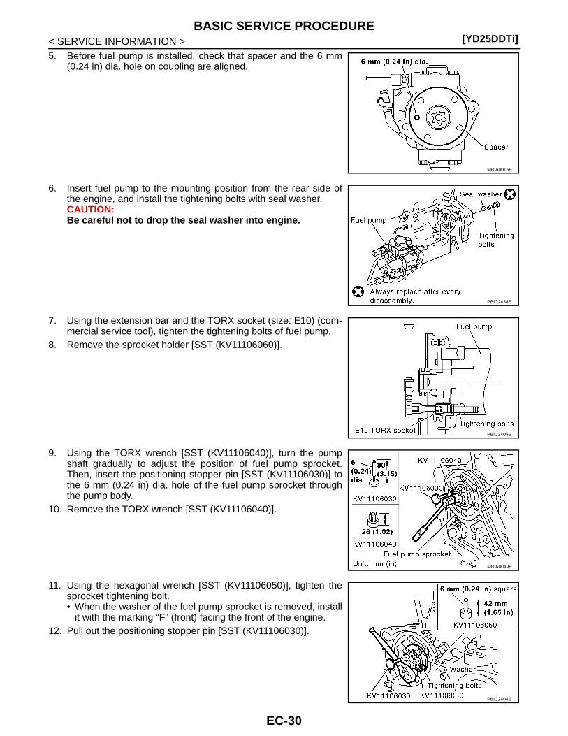
< SERVICE INFORMATION >5. Before fuel pump is installed, check that spacer and the 6 mm
(0.24 in) dia. hole on coupling are aligned.
6. Insert fuel pump to the mounting position from the rear side ofthe engine, and install the tightening bolts with seal washer.CAUTION:Be careful not to drop the seal washer into engine.
7. Using the extension bar and the TORX socket (size: E10) (com-mercial service tool), tighten the tightening bolts of fuel pump.
8. Remove the sprocket holder [SST (KV11106060)].
9. Using the TORX wrench [SST (KV11106040)], turn the pumpshaft gradually to adjust the position of fuel pump sprocket.Then, insert the positioning stopper pin [SST (KV11106030)] tothe 6 mm (0.24 in) dia. hole of the fuel pump sprocket throughthe pump body.
10. Remove the TORX wrench [SST (KV11106040)].
11. Using the hexagonal wrench [SST (KV11106050)], tighten thesprocket tightening bolt.• When the washer of the fuel pump sprocket is removed, install
it with the marking “F” (front) facing the front of the engine.12. Pull out the positioning stopper pin [SST (KV11106030)].
MBIA0016E
PBIC2438E
PBIC2405E
MBIA0049E
PBIC2404E
EC-30
BASIC SERVICE PROCEDURE[YD25DDTi]
C
D
E
F
G
H
I
J
K
L
M
A
C
N
P
O
< SERVICE INFORMATION >
E
13. Install secondary timing chain. Refer to “TIMING CHAIN” in EM section.14. Following steps below, install injection tube center. Refer to EM-8.a. Pre-set clip and insert rubber to injection tube center.b. Pre-tight nut of injection tube center to fuel pump and fuel rail by hand. (until seal surface touched)c. Adjust clip dimension and tight bolt for clip to intake manifold by tool.d. Tight nut of injection tube center to fuel pump by tool.e. Tight nut of injection tube center to fuel rail by tool.15. Connect the harness connector to fuel pump.16. Install fuel hoses. Refer to EM-8.17. Hereafter, install in the reverse order of removal.
CAUTION:When fuel pump is replaced with new one or another one, perform fuel pump leaning value clean-ing before starting engine. Refer to EC-23, "Fuel Pump Learning Value Clearing".
EC-31
[YD25DDTi]ON BOARD DIAGNOSTIC (OBD) SYSTEM
< SERVICE INFORMATION >
ON BOARD DIAGNOSTIC (OBD) SYSTEM
Introduction INFOID:0000000003759315
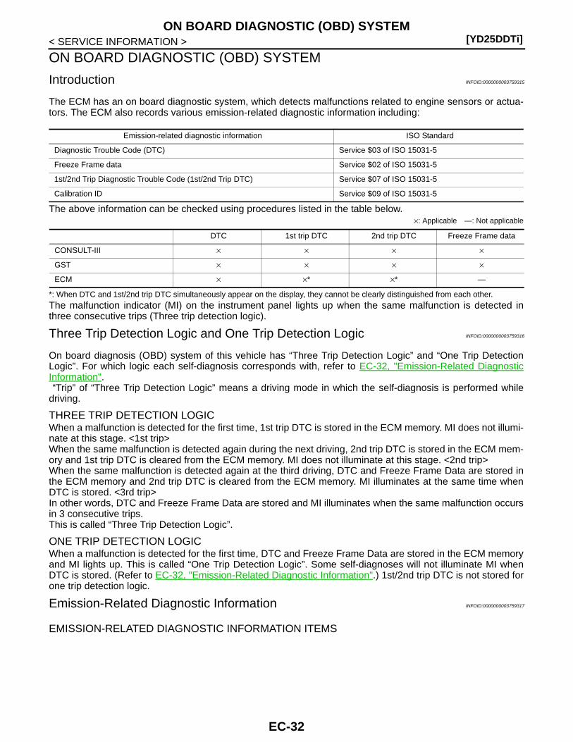
The ECM has an on board diagnostic system, which detects malfunctions related to engine sensors or actua-tors. The ECM also records various emission-related diagnostic information including:
The above information can be checked using procedures listed in the table below.×: Applicable —: Not applicable
*: When DTC and 1st/2nd trip DTC simultaneously appear on the display, they cannot be clearly distinguished from each other.
The malfunction indicator (MI) on the instrument panel lights up when the same malfunction is detected inthree consecutive trips (Three trip detection logic).
Three Trip Detection Logic and One Trip Detection Logic INFOID:0000000003759316
On board diagnosis (OBD) system of this vehicle has “Three Trip Detection Logic” and “One Trip DetectionLogic”. For which logic each self-diagnosis corresponds with, refer to EC-32, "Emission-Related DiagnosticInformation". “Trip” of “Three Trip Detection Logic” means a driving mode in which the self-diagnosis is performed whiledriving.
THREE TRIP DETECTION LOGICWhen a malfunction is detected for the first time, 1st trip DTC is stored in the ECM memory. MI does not illumi-nate at this stage. <1st trip>When the same malfunction is detected again during the next driving, 2nd trip DTC is stored in the ECM mem-ory and 1st trip DTC is cleared from the ECM memory. MI does not illuminate at this stage. <2nd trip>When the same malfunction is detected again at the third driving, DTC and Freeze Frame Data are stored inthe ECM memory and 2nd trip DTC is cleared from the ECM memory. MI illuminates at the same time whenDTC is stored. <3rd trip>In other words, DTC and Freeze Frame Data are stored and MI illuminates when the same malfunction occursin 3 consecutive trips.This is called “Three Trip Detection Logic”.
ONE TRIP DETECTION LOGICWhen a malfunction is detected for the first time, DTC and Freeze Frame Data are stored in the ECM memoryand MI lights up. This is called “One Trip Detection Logic”. Some self-diagnoses will not illuminate MI whenDTC is stored. (Refer to EC-32, "Emission-Related Diagnostic Information".) 1st/2nd trip DTC is not stored forone trip detection logic.
Emission-Related Diagnostic Information INFOID:0000000003759317
EMISSION-RELATED DIAGNOSTIC INFORMATION ITEMS
Emission-related diagnostic information ISO Standard
Diagnostic Trouble Code (DTC) Service $03 of ISO 15031-5
Freeze Frame data Service $02 of ISO 15031-5
1st/2nd Trip Diagnostic Trouble Code (1st/2nd Trip DTC) Service $07 of ISO 15031-5
Calibration ID Service $09 of ISO 15031-5
DTC 1st trip DTC 2nd trip DTC Freeze Frame data
CONSULT-III × × × ×
GST × × × ×
ECM × ×* ×* —
EC-32
ON BOARD DIAGNOSTIC (OBD) SYSTEM[YD25DDTi]
C
D
E
F
G
H
I
J
K
L
M
A
C
N
P
O
< SERVICE INFORMATION >
E
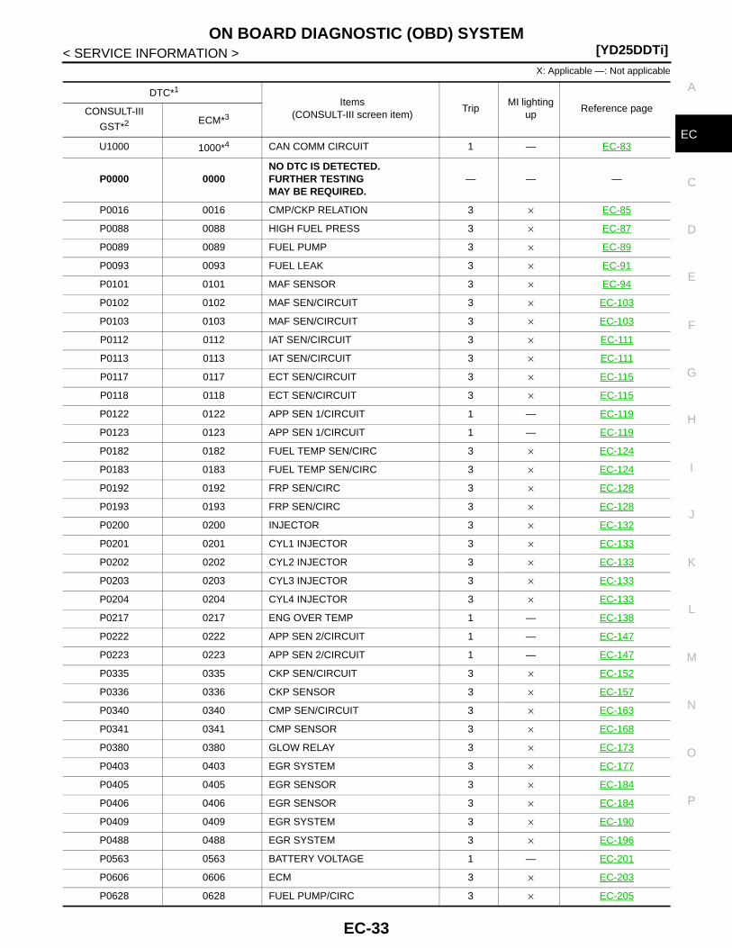
X: Applicable —: Not applicable
DTC*1
Items(CONSULT-III screen item)
TripMI lighting
upReference pageCONSULT-III
GST*2 ECM*3
U1000 1000*4 CAN COMM CIRCUIT 1 — EC-83
P0000 0000NO DTC IS DETECTED. FURTHER TESTINGMAY BE REQUIRED.
— — —
P0016 0016 CMP/CKP RELATION 3 × EC-85
P0088 0088 HIGH FUEL PRESS 3 × EC-87
P0089 0089 FUEL PUMP 3 × EC-89
P0093 0093 FUEL LEAK 3 × EC-91
P0101 0101 MAF SENSOR 3 × EC-94
P0102 0102 MAF SEN/CIRCUIT 3 × EC-103
P0103 0103 MAF SEN/CIRCUIT 3 × EC-103
P0112 0112 IAT SEN/CIRCUIT 3 × EC-111
P0113 0113 IAT SEN/CIRCUIT 3 × EC-111
P0117 0117 ECT SEN/CIRCUIT 3 × EC-115
P0118 0118 ECT SEN/CIRCUIT 3 × EC-115
P0122 0122 APP SEN 1/CIRCUIT 1 — EC-119
P0123 0123 APP SEN 1/CIRCUIT 1 — EC-119
P0182 0182 FUEL TEMP SEN/CIRC 3 × EC-124
P0183 0183 FUEL TEMP SEN/CIRC 3 × EC-124
P0192 0192 FRP SEN/CIRC 3 × EC-128
P0193 0193 FRP SEN/CIRC 3 × EC-128
P0200 0200 INJECTOR 3 × EC-132
P0201 0201 CYL1 INJECTOR 3 × EC-133
P0202 0202 CYL2 INJECTOR 3 × EC-133
P0203 0203 CYL3 INJECTOR 3 × EC-133
P0204 0204 CYL4 INJECTOR 3 × EC-133
P0217 0217 ENG OVER TEMP 1 — EC-138
P0222 0222 APP SEN 2/CIRCUIT 1 — EC-147
P0223 0223 APP SEN 2/CIRCUIT 1 — EC-147
P0335 0335 CKP SEN/CIRCUIT 3 × EC-152
P0336 0336 CKP SENSOR 3 × EC-157
P0340 0340 CMP SEN/CIRCUIT 3 × EC-163
P0341 0341 CMP SENSOR 3 × EC-168
P0380 0380 GLOW RELAY 3 × EC-173
P0403 0403 EGR SYSTEM 3 × EC-177
P0405 0405 EGR SENSOR 3 × EC-184
P0406 0406 EGR SENSOR 3 × EC-184
P0409 0409 EGR SYSTEM 3 × EC-190
P0488 0488 EGR SYSTEM 3 × EC-196
P0563 0563 BATTERY VOLTAGE 1 — EC-201
P0606 0606 ECM 3 × EC-203
P0628 0628 FUEL PUMP/CIRC 3 × EC-205
EC-33

[YD25DDTi]ON BOARD DIAGNOSTIC (OBD) SYSTEM
< SERVICE INFORMATION >
*1: 1st trip DTC No. and 2nd trip DTC No. are the same as DTC No.
*2: This number is prescribed by ISO 15031-6.
*3: In Diagnostic Test Mode II (Self-diagnostic results).
*4: The troubleshooting for this DTC needs CONSULT-III.
DTC AND 1ST/2ND TRIP DTCThe number of 1st/2nd trip DTC is the same as the number of DTC.When a malfunction is detected during 1st trip, 1st trip DTC is stored in the ECM memory. MI does not illumi-nate at this time. When the same malfunction is detected in the next trip (2nd trip), 2nd trip DTC is stored in theECM memory and 1st trip DTC is cleared from the ECM memory. MI does not illuminate at this time. In addi-tion, DTC is stored in the ECM memory and MI lights up when the same malfunction is detected during the fol-lowing consecutive trip (3rd trip). The procedure for erasing DTC, 1st trip DTC, and 2nd trip DTC from the ECM memory is described in “HOWTO ERASE EMISSION-RELATED DIAGNOSTIC INFORMATION”.
P0629 0629 FUEL PUMP/CIRC 3 × EC-205
P0642 0642 SENSOR PWR/CIRC1 3 × EC-210
P0643 0643 SENSOR PWR/CIRC1 3 × EC-210
P0652 0652 SENSOR PWR/CIRC2 3 × EC-214
P0653 0653 SENSOR PWR/CIRC2 3 × EC-214
P0668 0668 ECM 3 × EC-218
P0669 0669 ECM 3 × EC-218
P0686 0686 ECM RELAY 1 — EC-220
P1268 1268 INJECTOR 1 1 — EC-227
P1269 1269 INJECTOR 2 1 — EC-227
P1270 1270 INJECTOR 3 1 — EC-227
P1271 1271 INJECTOR 4 1 — EC-227
P1272 1272 FRP RELIEF VALVE 3 × EC-234
P1273 1273 FUEL PUMP 3 × EC-234
P1274 1274 FUEL PUMP 1 × EC-234
P1275 1275 FUEL PUMP 1 × EC-234
P1610 1610 LOCK MODE 1 — EL-102
P1611 1611 ID DISCORD, IMM-ECM 1 — EL-103
P1612 1612 CHAIN OF ECM-IMMU 1 — EL-103
P1614 1614 CHAIN OF IMMU-KEY 1 — EL-105
P1615 1615 DIFFERENCE OF KEY 1 — EL-106
P1616 1616 ECM 1 — EL-106
P1622 1622 INJ ADJ VAL UNRGST 1 — EC-254
P1623 1623 INJ ADJ VAL ERROR 1 — EC-255
P2135 2135 APP SENSOR 1 — EC-257
P2146 2146 INJ PWR/CIRC 3 × EC-262
P2147 2147 INJECTOR/CIRC 3 × EC-266
P2148 2148 INJECTOR/CIRC 3 × EC-266
P2149 2149 INJ PWR/CIRC 3 × EC-262
P2228 2228 BARO SEN/CIRC 3 × EC-271
P2229 2229 BARO SEN/CIRC 3 × EC-271
DTC*1
Items(CONSULT-III screen item)
TripMI lighting
upReference pageCONSULT-III
GST*2 ECM*3
EC-34
ON BOARD DIAGNOSTIC (OBD) SYSTEM[YD25DDTi]
C
D
E
F
G
H
I
J
K
L
M
A
C
N
P
O
< SERVICE INFORMATION >
E
For malfunctions in which 1st/2nd trip DTC are displayed, Refer to “EMISSION-RELATED DIAGNOSTICINFORMATION ITEMS”.1st/2nd trip DTC is specified in Service $07 of ISO15031-5. 1st/2nd trip DTC detection occurs without lightingup MI and therefore does not warn the driver of a malfunction.When 1st/2nd trip DTC is detected, check, print out or write down, and erase 1st/2nd trip DTC as specifiedwith step II of Work Flow, refer to EC-41, "Trouble Diagnosis Introduction". Then perform DTC ConfirmationProcedure or Overall Function Check to try to duplicate the malfunction. If the malfunction is duplicated, it isnecessary to investigate the cause again.
How to Read DTC and 1st/2nd Trip DTCDTC and 1st/2nd trip DTC can be read by the following procedures.
With CONSULT-III With GST
CONSULT-III or GST (Generic Scan Tool): Examples: P0117, P0335, P1268, etc.These numbers are prescribed by ISO 15031-6.(CONSULT-III also displays the malfunctioning parts and systems.)A sample of CONSULT-III display for DTC and 1st/2nd trip DTC is shown in the figure. DTC and 1st/2nd tripDTC are displayed in the “SELF-DIAG RESULTS” mode of CONSULT-III.“TIME” data shows how many times the vehicle was driven after the last detection of DTC or 1st/2nd trip DTC.When DTC or 1st/2nd trip DTC has been detected currently, “TIME” becomes “0”.• CONSULT-III displays for DTC and 1st/2nd trip DTC become the same.• The output of a DTC indicates a malfunction. However, GST does not indicate whether the malfunction is still
occurring or has occurred in the past and has returned to normal. CONSULT-III can identify the malfunctionstatus. Therefore the use of CONSULT-III (If available) is recommended.
FREEZE FRAME DATAECM records driving conditions such as calculated load value, engine coolant temperature, engine speed,vehicle speed, and intake manifold pressure at the moment a malfunction is detected.The data stored together with DTC is called Freeze Frame Data, and is displayed on CONSULT-III or GST.When 1st/2nd trip DTC is detected, Freeze Frame Data is not recorded.Only a set of Freeze Frame Data can be stored in the ECM memory. When ECM records Freeze Frame Data,and another Freeze Frame Data is generated after that, the first (original) Freeze Frame Data is not updated inECM and it remains.When the DTC is erased from ECM memory, Freeze Frame Data is erased with DTC. The procedure for eras-ing DTC is described in “HOW TO ERASE EMISSION-RELATED DIAGNOSTIC INFORMATION”.
HOW TO ERASE EMISSION-RELATED DIAGNOSTIC INFORMATION
How to Erase DTC and 1st Trip DTC WITH CONSULT-III
NOTE:• If the ignition switch stays ON after repair work, be sure to turn ignition switch OFF once. Wait at least 10
seconds and then turn it ON (engine stopped) again.1. Select “ENGINE” with CONSULT-III.2. Select “SELF-DIAG RESULTS”.3. Touch “ERASE”. (DTC in ECM will be erased.)
WITH GSTNOTE:• If the ignition switch stays ON after repair work, be sure to turn ignition switch OFF once. Wait at least 10
seconds and then turn it ON (engine stopped) again. NO TOOLS
NOTE:• If the ignition switch stays ON after repair work, be sure to turn ignition switch OFF once. Wait at least 10
seconds and then turn it ON (engine stopped) again.• If the battery is disconnected, the emission-related diagnostic information will be lost within 24
hours.• The following data are cleared when the ECM memory is erased.- Diagnostic trouble codes- 1st trip diagnostic trouble codes- 2nd trip diagnostic trouble codes- Freeze frame data
EC-35
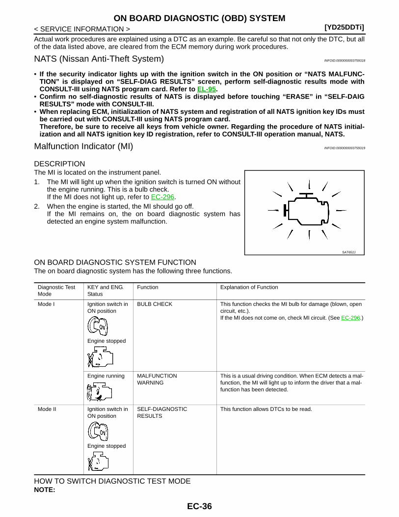
[YD25DDTi]ON BOARD DIAGNOSTIC (OBD) SYSTEM
< SERVICE INFORMATION >Actual work procedures are explained using a DTC as an example. Be careful so that not only the DTC, but allof the data listed above, are cleared from the ECM memory during work procedures.
NATS (Nissan Anti-Theft System) INFOID:0000000003759318
• If the security indicator lights up with the ignition switch in the ON position or “NATS MALFUNC-TION” is displayed on “SELF-DIAG RESULTS” screen, perform self-diagnostic results mode withCONSULT-III using NATS program card. Refer to EL-95.
• Confirm no self-diagnostic results of NATS is displayed before touching “ERASE” in “SELF-DAIGRESULTS” mode with CONSULT-III.
• When replacing ECM, initialization of NATS system and registration of all NATS ignition key IDs mustbe carried out with CONSULT-III using NATS program card.Therefore, be sure to receive all keys from vehicle owner. Regarding the procedure of NATS initial-ization and all NATS ignition key ID registration, refer to CONSULT-III operation manual, NATS.
Malfunction Indicator (MI) INFOID:0000000003759319
DESCRIPTIONThe MI is located on the instrument panel.1. The MI will light up when the ignition switch is turned ON without
the engine running. This is a bulb check.If the MI does not light up, refer to EC-296.
2. When the engine is started, the MI should go off.If the MI remains on, the on board diagnostic system hasdetected an engine system malfunction.
ON BOARD DIAGNOSTIC SYSTEM FUNCTIONThe on board diagnostic system has the following three functions.
HOW TO SWITCH DIAGNOSTIC TEST MODENOTE:
SAT652J
Diagnostic Test Mode
KEY and ENG. Status
Function Explanation of Function
Mode I Ignition switch in ON position
Engine stopped
BULB CHECK This function checks the MI bulb for damage (blown, open circuit, etc.).If the MI does not come on, check MI circuit. (See EC-296.)
Engine running MALFUNCTIONWARNING
This is a usual driving condition. When ECM detects a mal-function, the MI will light up to inform the driver that a mal-function has been detected.
Mode II Ignition switch in ON position
Engine stopped
SELF-DIAGNOSTICRESULTS
This function allows DTCs to be read.
EC-36
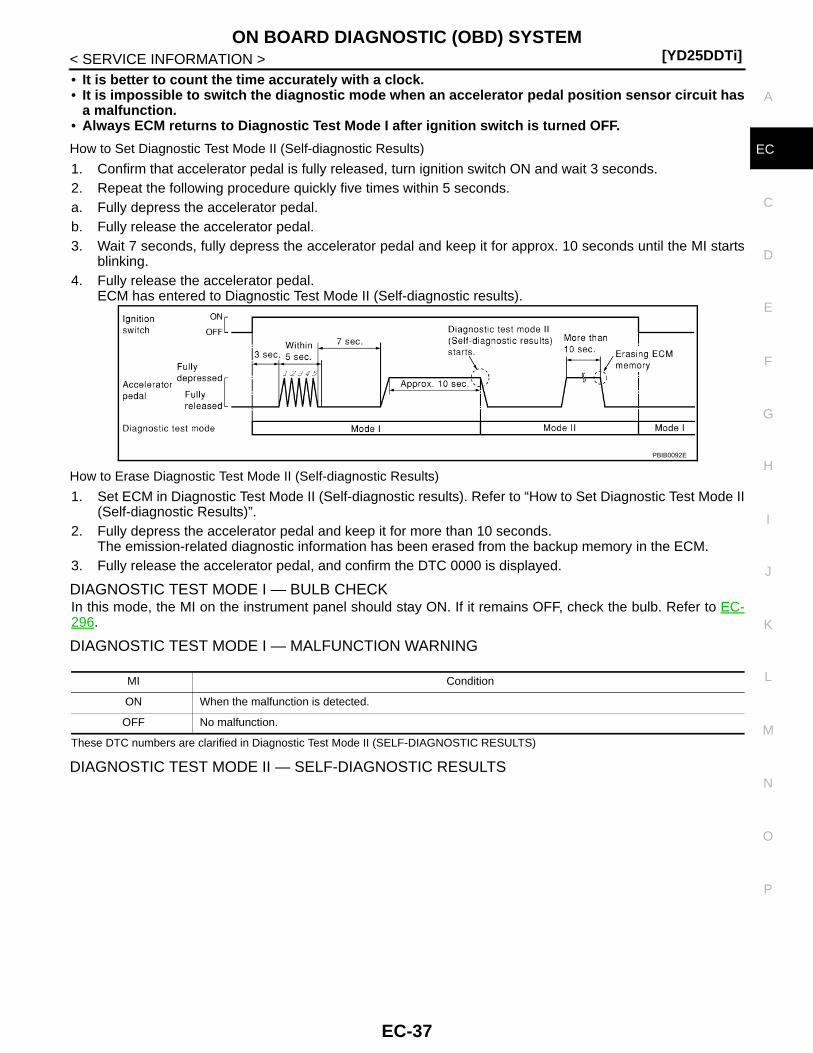
ON BOARD DIAGNOSTIC (OBD) SYSTEM[YD25DDTi]
C
D
E
F
G
H
I
J
K
L
M
A
C
N
P
O
< SERVICE INFORMATION >
E
• It is better to count the time accurately with a clock.• It is impossible to switch the diagnostic mode when an accelerator pedal position sensor circuit has
a malfunction.• Always ECM returns to Diagnostic Test Mode I after ignition switch is turned OFF.
How to Set Diagnostic Test Mode II (Self-diagnostic Results)
1. Confirm that accelerator pedal is fully released, turn ignition switch ON and wait 3 seconds.2. Repeat the following procedure quickly five times within 5 seconds.a. Fully depress the accelerator pedal.b. Fully release the accelerator pedal.3. Wait 7 seconds, fully depress the accelerator pedal and keep it for approx. 10 seconds until the MI starts
blinking.4. Fully release the accelerator pedal.
ECM has entered to Diagnostic Test Mode II (Self-diagnostic results).
How to Erase Diagnostic Test Mode II (Self-diagnostic Results)
1. Set ECM in Diagnostic Test Mode II (Self-diagnostic results). Refer to “How to Set Diagnostic Test Mode II(Self-diagnostic Results)”.
2. Fully depress the accelerator pedal and keep it for more than 10 seconds.The emission-related diagnostic information has been erased from the backup memory in the ECM.
3. Fully release the accelerator pedal, and confirm the DTC 0000 is displayed.
DIAGNOSTIC TEST MODE I — BULB CHECKIn this mode, the MI on the instrument panel should stay ON. If it remains OFF, check the bulb. Refer to EC-296.
DIAGNOSTIC TEST MODE I — MALFUNCTION WARNING
These DTC numbers are clarified in Diagnostic Test Mode II (SELF-DIAGNOSTIC RESULTS)
DIAGNOSTIC TEST MODE II — SELF-DIAGNOSTIC RESULTS
PBIB0092E
MI Condition
ON When the malfunction is detected.
OFF No malfunction.
EC-37
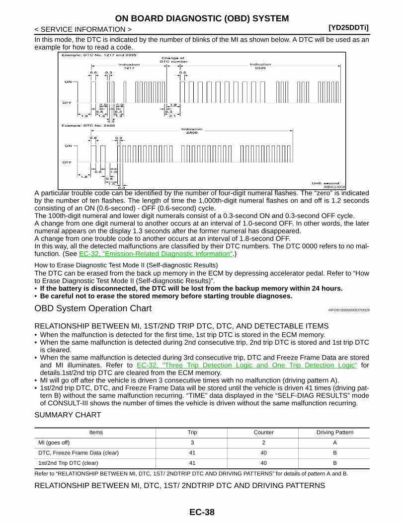
[YD25DDTi]ON BOARD DIAGNOSTIC (OBD) SYSTEM
< SERVICE INFORMATION >In this mode, the DTC is indicated by the number of blinks of the MI as shown below. A DTC will be used as anexample for how to read a code.
A particular trouble code can be identified by the number of four-digit numeral flashes. The “zero” is indicatedby the number of ten flashes. The length of time the 1,000th-digit numeral flashes on and off is 1.2 secondsconsisting of an ON (0.6-second) - OFF (0.6-second) cycle.The 100th-digit numeral and lower digit numerals consist of a 0.3-second ON and 0.3-second OFF cycle.A change from one digit numeral to another occurs at an interval of 1.0-second OFF. In other words, the laternumeral appears on the display 1.3 seconds after the former numeral has disappeared.A change from one trouble code to another occurs at an interval of 1.8-second OFF.In this way, all the detected malfunctions are classified by their DTC numbers. The DTC 0000 refers to no mal-function. (See EC-32, "Emission-Related Diagnostic Information".)
How to Erase Diagnostic Test Mode II (Self-diagnostic Results)The DTC can be erased from the back up memory in the ECM by depressing accelerator pedal. Refer to “Howto Erase Diagnostic Test Mode II (Self-diagnostic Results)”.• If the battery is disconnected, the DTC will be lost from the backup memory within 24 hours.• Be careful not to erase the stored memory before starting trouble diagnoses.
OBD System Operation Chart INFOID:0000000003759320
RELATIONSHIP BETWEEN MI, 1ST/2ND TRIP DTC, DTC, AND DETECTABLE ITEMS• When the malfunction is detected for the first time, 1st trip DTC is stored in the ECM memory.• When the same malfunction is detected during 2nd consecutive trip, 2nd trip DTC is stored and 1st trip DTC
is cleared.• When the same malfunction is detected during 3rd consecutive trip, DTC and Freeze Frame Data are stored
and MI illuminates. Refer to EC-32, "Three Trip Detection Logic and One Trip Detection Logic" fordetails.1st/2nd trip DTC are cleared from the ECM memory.
• MI will go off after the vehicle is driven 3 consecutive times with no malfunction (driving pattern A).• 1st/2nd trip DTC, DTC, and Freeze Frame Data will be stored until the vehicle is driven 41 times (driving pat-
tern B) without the same malfunction recurring. “TIME” data displayed in the “SELF-DIAG RESULTS” modeof CONSULT-III shows the number of times the vehicle is driven without the same malfunction recurring.
SUMMARY CHART
Refer to “RELATIONSHIP BETWEEN MI, DTC, 1ST/ 2NDTRIP DTC AND DRIVING PATTERNS” for details of pattern A and B.
RELATIONSHIP BETWEEN MI, DTC, 1ST/ 2NDTRIP DTC AND DRIVING PATTERNS
JMBIA1140GB
Items Trip Counter Driving Pattern
MI (goes off) 3 2 A
DTC, Freeze Frame Data (clear) 41 40 B
1st/2nd Trip DTC (clear) 41 40 B
EC-38
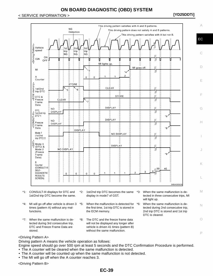
ON BOARD DIAGNOSTIC (OBD) SYSTEM[YD25DDTi]
C
D
E
F
G
H
I
J
K
L
M
A
C
N
P
O
< SERVICE INFORMATION >
E
<Driving Pattern A>Driving pattern A means the vehicle operation as follows:Engine speed should go over 500 rpm at least 5 seconds and the DTC Confirmation Procedure is performed.• The A counter will be cleared when the same malfunction is detected.• The A counter will be counted up when the same malfunction is not detected.• The MI will go off when the A counter reaches 3.
<Driving Pattern B>
*1: CONSULT-III displays for DTC and 1st/2nd trip DTC become the same.
*2: 1st/2nd trip DTC becomes the same display in mode7 of GST.
*3: When the same malfunction is de-tected in three consecutive trips, MI will light up.
*4: MI will go off after vehicle is driven 3 times (pattern A) without any mal-functions.
*5: When the malfunction is detected for the first time, 1st trip DTC is stored in the ECM memory.
*6: When the same malfunction is de-tected during 2nd consecutive trip, 2nd trip DTC is stored and 1st trip DTC is cleared.
*7: When the same malfunction is de-tected during 3rd consecutive trip, DTC and Freeze Frame Data are stored.
*8: The DTC and the freeze frame data will not be displayed any longer after vehicle is driven 41 times (pattern B) without the same malfunction.
JMBIA0956GB
EC-39
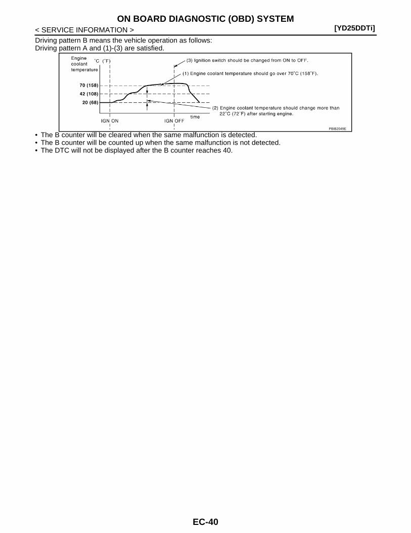
[YD25DDTi]ON BOARD DIAGNOSTIC (OBD) SYSTEM
< SERVICE INFORMATION >Driving pattern B means the vehicle operation as follows:Driving pattern A and (1)-(3) are satisfied.
• The B counter will be cleared when the same malfunction is detected.• The B counter will be counted up when the same malfunction is not detected.• The DTC will not be displayed after the B counter reaches 40.
PBIB2049E
EC-40

TROUBLE DIAGNOSIS[YD25DDTi]
C
D
E
F
G
H
I
J
K
L
M
A
C
N
P
O
< SERVICE INFORMATION >
E
TROUBLE DIAGNOSIS
Trouble Diagnosis Introduction INFOID:0000000003759321
INTRODUCTIONThe engine has an ECM to control major systems such as fuel injec-tion control, fuel injection timing control, glow control system, etc.The ECM accepts input signals from sensors and instantly actuators.It is essential that both input and output signals are proper and sta-ble. At the same time, it is important that there are no malfunctionssuch as vacuum leaks, or other malfunctions with the engine.
It is much more difficult to diagnose a malfunction that occurs inter-mittently rather than continuously. Most intermittent malfunctions arecaused by poor electric connections or improper wiring. In this case,careful checking of suspected circuits may help prevent the replace-ment of good parts.
A visual check only may not find the cause of the incidents. A roadtest with CONSULT-III (or GST) or a circuit tester connected shouldbe performed. Follow the “WORK FLOW”.Before undertaking actual checks, take a few minutes to talk with acustomer who approaches with a driveability complaint. The cus-tomer can supply good information about such incidents, especiallyintermittent ones. Find out what symptoms are present and underwhat conditions they occur. A Diagnostic Worksheet like the exampleon “WORK FLOW” should be used.Start your diagnosis by looking for conventional incidents first. Thiswill help troubleshoot driveability incidents on an electronically con-trolled engine vehicle.
WORK FLOW
MEF036D
SEF233G
SEF234G
EC-41
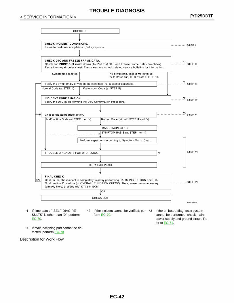
[YD25DDTi]TROUBLE DIAGNOSIS
< SERVICE INFORMATION >
Description for Work Flow
*1 If time data of “SELF-DIAG RE-SULTS” is other than “0”, perform EC-70.
*2 If the incident cannot be verified, per-form EC-70.
*3 If the on board diagnostic system cannot be performed, check main power supply and ground circuit. Re-fer to EC-71.
*4 If malfunctioning part cannot be de-tected, perform EC-70.
PBIB2047E
EC-42

TROUBLE DIAGNOSIS[YD25DDTi]
C
D
E
F
G
H
I
J
K
L
M
A
C
N
P
O
< SERVICE INFORMATION >
E
DIAGNOSTIC WORK SHEETThere are many operating conditions that lead to the malfunction ofengine components. A good grasp of such conditions can make trou-bleshooting faster and more accurate.In general, each customer feels differently about an incident. It isimportant to fully understand the symptoms or conditions for a cus-tomer complaint.Utilize a diagnostic worksheet like the one shown below in order toorganize all the information for troubleshooting.
STEP DESCRIPTION
STEP IGet detailed information about the conditions and the environment when the incident/symptom occurred using the “DI-AGNOSTIC WORK SHEET”.
STEP II
Before confirming the concern, check and write down (print out using CONSULT-III or GST) the (1st/2nd trip) DTC and the freeze frame data (When 1st/2nd trip DTC is detected, Freeze Frame Data is not recorded.), then erase the DTC and the data. (Refer to EC-32, "Emission-Related Diagnostic Information".) The (1st/2nd trip) DTC and the freeze frame data can be used when duplicating the incident at STEP III & IV.If the incident cannot be verified, perform EC-70.Study the relationship between the cause, specified by (1st/2nd trip) DTC, and the symptom described by the custom-er. (The Symptom Matrix Chart will be useful. See EC-48, "Symptom Matrix Chart".)Also check related service bulletins for information.
STEP III
Try to confirm the symptom and under what conditions the incident occurs.The DIAGNOSTIC WORK SHEET and the freeze frame data are useful to verify the incident. Connect CONSULT-III to the vehicle and check real time diagnosis results.If the incident cannot be verified, perform EC-70.If the malfunction code is detected, skip STEP IV and perform STEP V.
STEP IV
Try to detect the (1st/2nd trip) DTC by driving in (or performing) the DTC Confirmation Procedure. Check and read the (1st/2nd trip) DTC and freeze frame data by using CONSULT-III or GST.If the incident cannot be verified, perform EC-70.In case the DTC Confirmation Procedure is not available, perform the Overall Function Check instead. The (1st/2nd trip) DTC cannot be displayed by this check, however, this simplified check is an effective alternative.The NG result of the Overall Function Check is the same as the (1st/2nd trip) DTC detection.
STEP V
Take the appropriate action based on the results of STEP I through IV.If the malfunction code is indicated, proceed to TROUBLE DIAGNOSIS FOR DTC PXXXX.If the normal code is indicated, proceed to the BASIC INSPECTION. (Refer to EC-45, "Basic Inspection".) Then per-form inspections according to the Symptom Matrix Chart. (Refer to EC-48, "Symptom Matrix Chart".)
STEP VI
Identify where to begin diagnosis based on the relationship study between symptom and possible causes. Inspect the system for mechanical binding, loose connectors or wiring damage using (tracing) Harness Layouts.Check the voltage of the related ECM terminals or monitor the output data from the related sensors with CONSULT-III. Refer to EC-57, "ECM Terminal and Reference Value", EC-68, "CONSULT-III Reference Value in Data Monitor Mode".The Diagnostic Procedure in EC section contains a description based on open circuit inspection. A short circuit inspec-tion is also required for the circuit check in the Diagnostic Procedure. For details, refer to “SERVICE INFORMATION FOR ELECTRICAL INCIDENT”.Repair or replace the malfunction parts.If malfunctioning part cannot be detected, perform EC-70.
STEP VII
Once you have repaired the circuit or replaced a component, you need to run the engine in the same conditions and circumstances which resulted in the customer's initial complaint.Perform the DTC Confirmation Procedure and confirm the normal code [DTC No. P0000] is detected. If the incident is still detected in the final check, perform STEP VI by using a method different from the previous one.Before returning the vehicle to the customer, be sure to erase the unnecessary (already fixed) (1st/2nd trip) DTC in ECM. (Refer to EC-32, "Emission-Related Diagnostic Information".)
SEF907L
EC-43
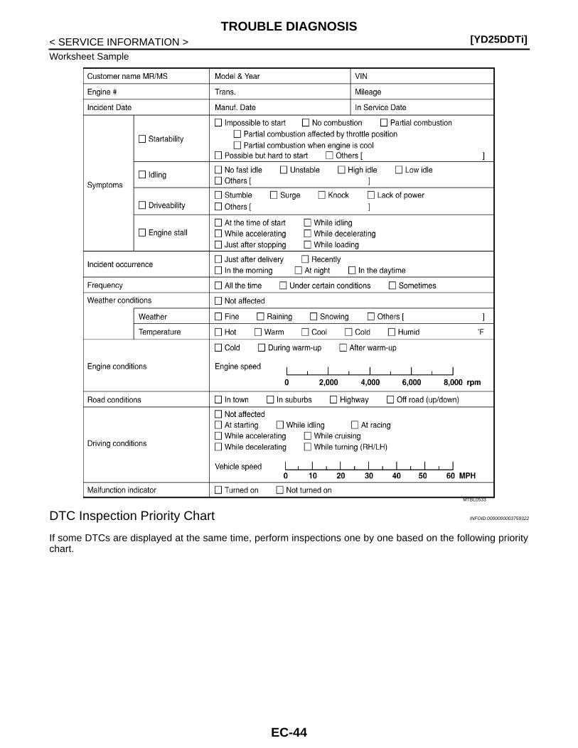
[YD25DDTi]TROUBLE DIAGNOSIS
< SERVICE INFORMATION >Worksheet Sample
DTC Inspection Priority Chart INFOID:0000000003759322
If some DTCs are displayed at the same time, perform inspections one by one based on the following prioritychart.
MTBL0533
EC-44

TROUBLE DIAGNOSIS[YD25DDTi]
C
D
E
F
G
H
I
J
K
L
M
A
C
N
P
O
< SERVICE INFORMATION >
E
Basic Inspection INFOID:0000000003759324
Precaution:Perform Basic Inspection without electrical or mechanical loads applied.• Headlamp switch is OFF.- For vehicles equipped with daytime light systems, perform one of the following procedures before starting
engine not to illuminate headlamps.• Apply parking brake• Set lighting switch to the 1st position• Air conditioner switch is OFF.• Rear defogger switch is OFF.• Steering wheel is in the straight-ahead position, etc.
1.INSPECTION START
1. Check service records for any recent repairs that may indicate a related malfunction.2. Check the current need for scheduled maintenance, especially for fuel filter and air cleaner filter. Refer to
MA-3 (For Europe),MA-8 (For Australia).3. Open engine hood and check the following:- Harness connectors for improper connections- Vacuum hoses for splits, kinks, or improper connections- Wiring for improper connections, pinches, or cuts4. Start engine and warm it up to the normal operating tempera-
ture.
>> GO TO 2.
2.PREPARATION FOR CHECKING IDLE SPEED
Priority Detected items (DTC)
1 • U1000 CAN communication line• P0016 Crankshaft position - camshaft position correlation• P0101 P0102 P0103 Mass air flow sensor• P0112 P0113 Intake air temperature sensor• P0117 P0118 Engine coolant temperature sensor• P0122 P0123 P0222 P0223 P2135 Accelerator pedal position sensor• P0182 P0183 Fuel pump temperature sensor• P0192 P0193 Fuel rail pressure sensor• P0335 P0336 Crankshaft position sensor• P0340 P0341 Camshaft position sensor• P0563 Battery voltage• P0606 P0668 P0669 ECM• P0642 P0643 P0652 P0653 Sensor power supply• P1610 - P1616 NATS• P1622 P1623 Injector adjustment value• P2228 P2229 Barometric pressure sensor
2 • P0089 P0628 P0629 P1272 - P1275 Fuel pump• P0200 - P0204 P1268 - P1271 P2146 - P2149 Fuel injector• P0380 Glow relay• P0405 P0406 EGR volume control valve control position sensor• P0686 ECM relay
3 • P0088 P0093 Fuel system• P0217 Engine over temperature (OVERHEAT)• P0403 P0409 P0488 EGR function
SEF142I
EC-45
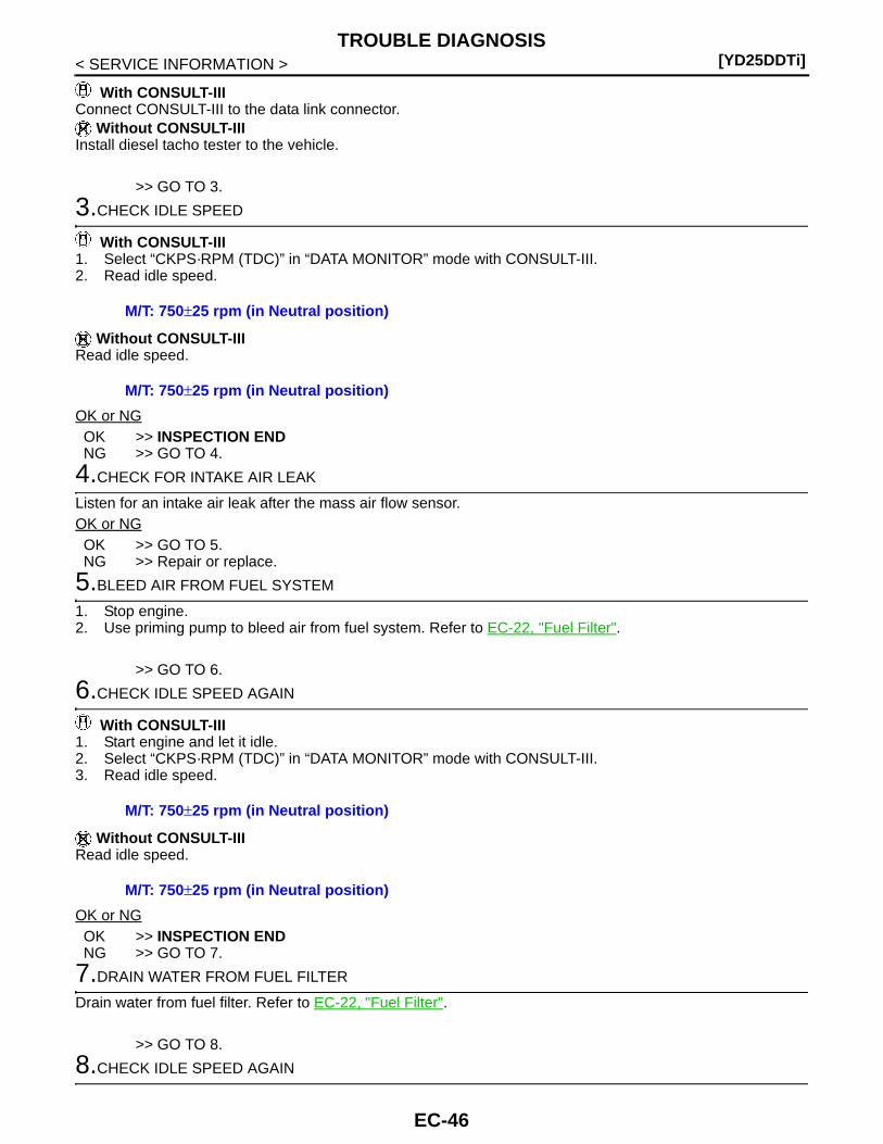
[YD25DDTi]TROUBLE DIAGNOSIS
< SERVICE INFORMATION >
With CONSULT-IIIConnect CONSULT-III to the data link connector.
Without CONSULT-IIIInstall diesel tacho tester to the vehicle.
>> GO TO 3.
3.CHECK IDLE SPEED
With CONSULT-III1. Select “CKPS·RPM (TDC)” in “DATA MONITOR” mode with CONSULT-III.2. Read idle speed.
Without CONSULT-IIIRead idle speed.
OK or NGOK >> INSPECTION ENDNG >> GO TO 4.
4.CHECK FOR INTAKE AIR LEAK
Listen for an intake air leak after the mass air flow sensor.OK or NGOK >> GO TO 5.NG >> Repair or replace.
5.BLEED AIR FROM FUEL SYSTEM
1. Stop engine.2. Use priming pump to bleed air from fuel system. Refer to EC-22, "Fuel Filter".
>> GO TO 6.
6.CHECK IDLE SPEED AGAIN
With CONSULT-III1. Start engine and let it idle.2. Select “CKPS·RPM (TDC)” in “DATA MONITOR” mode with CONSULT-III.3. Read idle speed.
Without CONSULT-IIIRead idle speed.
OK or NGOK >> INSPECTION ENDNG >> GO TO 7.
7.DRAIN WATER FROM FUEL FILTER
Drain water from fuel filter. Refer to EC-22, "Fuel Filter".
>> GO TO 8.
8.CHECK IDLE SPEED AGAIN
M/T: 750±25 rpm (in Neutral position)
M/T: 750±25 rpm (in Neutral position)
M/T: 750±25 rpm (in Neutral position)
M/T: 750±25 rpm (in Neutral position)
EC-46
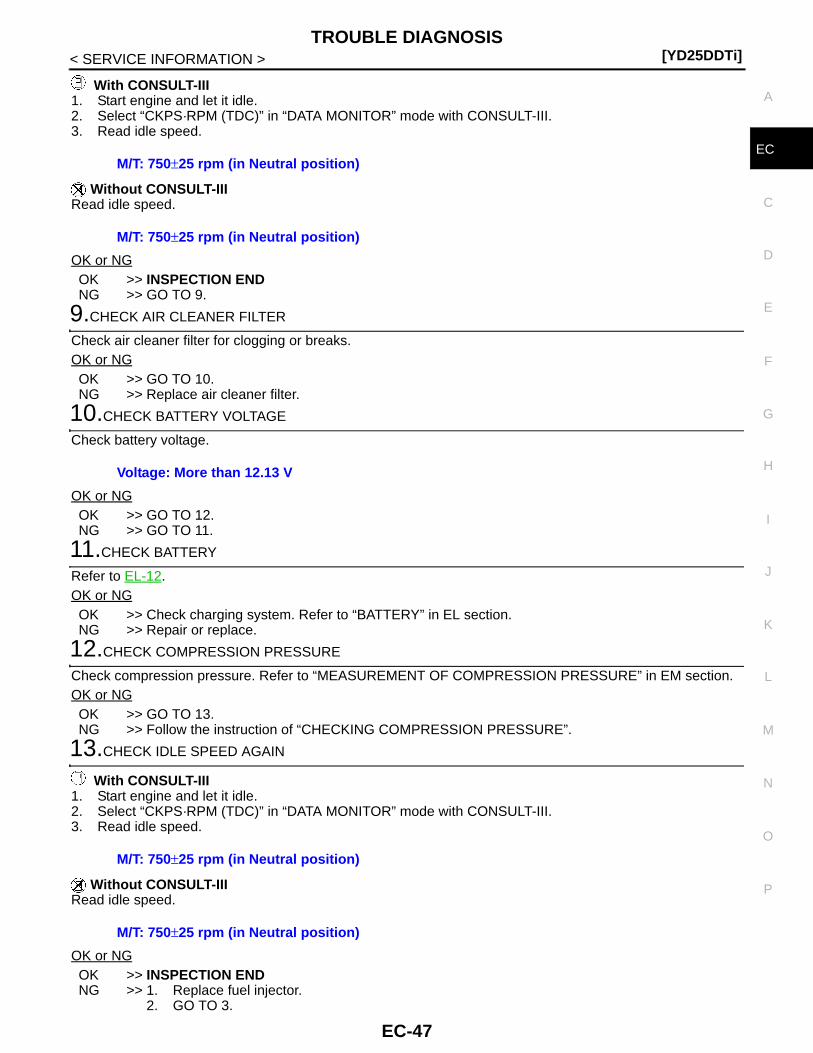
TROUBLE DIAGNOSIS[YD25DDTi]
C
D
E
F
G
H
I
J
K
L
M
A
C
N
P
O
< SERVICE INFORMATION >
E
With CONSULT-III1. Start engine and let it idle.2. Select “CKPS·RPM (TDC)” in “DATA MONITOR” mode with CONSULT-III.3. Read idle speed.
Without CONSULT-IIIRead idle speed.
OK or NGOK >> INSPECTION ENDNG >> GO TO 9.
9.CHECK AIR CLEANER FILTER
Check air cleaner filter for clogging or breaks.OK or NGOK >> GO TO 10.NG >> Replace air cleaner filter.
10.CHECK BATTERY VOLTAGE
Check battery voltage.
OK or NGOK >> GO TO 12.NG >> GO TO 11.
11.CHECK BATTERY
Refer to EL-12.OK or NGOK >> Check charging system. Refer to “BATTERY” in EL section.NG >> Repair or replace.
12.CHECK COMPRESSION PRESSURE
Check compression pressure. Refer to “MEASUREMENT OF COMPRESSION PRESSURE” in EM section.OK or NGOK >> GO TO 13.NG >> Follow the instruction of “CHECKING COMPRESSION PRESSURE”.
13.CHECK IDLE SPEED AGAIN
With CONSULT-III1. Start engine and let it idle.2. Select “CKPS·RPM (TDC)” in “DATA MONITOR” mode with CONSULT-III.3. Read idle speed.
Without CONSULT-IIIRead idle speed.
OK or NGOK >> INSPECTION ENDNG >> 1. Replace fuel injector.
2. GO TO 3.
M/T: 750±25 rpm (in Neutral position)
M/T: 750±25 rpm (in Neutral position)
Voltage: More than 12.13 V
M/T: 750±25 rpm (in Neutral position)
M/T: 750±25 rpm (in Neutral position)
EC-47

[YD25DDTi]TROUBLE DIAGNOSIS
< SERVICE INFORMATION >
Symptom Matrix Chart INFOID:0000000003759325
SYSTEM — Basic engine control system
SYMPTOM
Ref
eren
ce p
age
HA
RD
/NO
STA
RT
/RE
STA
RT
(E
XC
P. H
A)
EN
GIN
E S
TALL
HE
SIT
AT
ION
/SU
RG
ING
/FLA
T S
PO
T
KN
OC
K/D
ET
ON
AT
ION
LAC
K O
F P
OW
ER
PO
OR
AC
CE
LER
AT
ION
HI I
DLE
LOW
IDLE
NO
STA
RT
(w
ith fi
rst f
iring
)
NO
STA
RT
(w
ithou
t firs
t firi
ng)
HA
RD
TO
STA
RT
WH
EN
EN
GIN
E IS
CO
LD
HA
RD
TO
STA
RT
WH
EN
EN
GIN
E IS
HO
T
AT
IDLE
DU
RIN
G D
RIV
ING
WH
EN
DE
CE
LER
AT
ING
Warranty symptom code AA AB AC AD AE AF
Fuel pump 5 5 5 5 5 5 5 5 5 5 5 —
Fuel filter 1 1 1 1 1 EC-22
Fuel injector 3 3 3 3 3 3 3 3 3 4 4 3 3 EC-133
Glow control system 1 1 1 1 1 EC-273
Engine body 3 3 3 3 3 3 3 3 4 4 3 EM-18
EGR system 3 3EC-177,EC-190,EC-196
Air cleaner and duct 3 3Refer to Service Manual
Fuel rail pressure relief valve 3 3 3 3 3 3 3 3 3 3 3 EC-91
EC-48
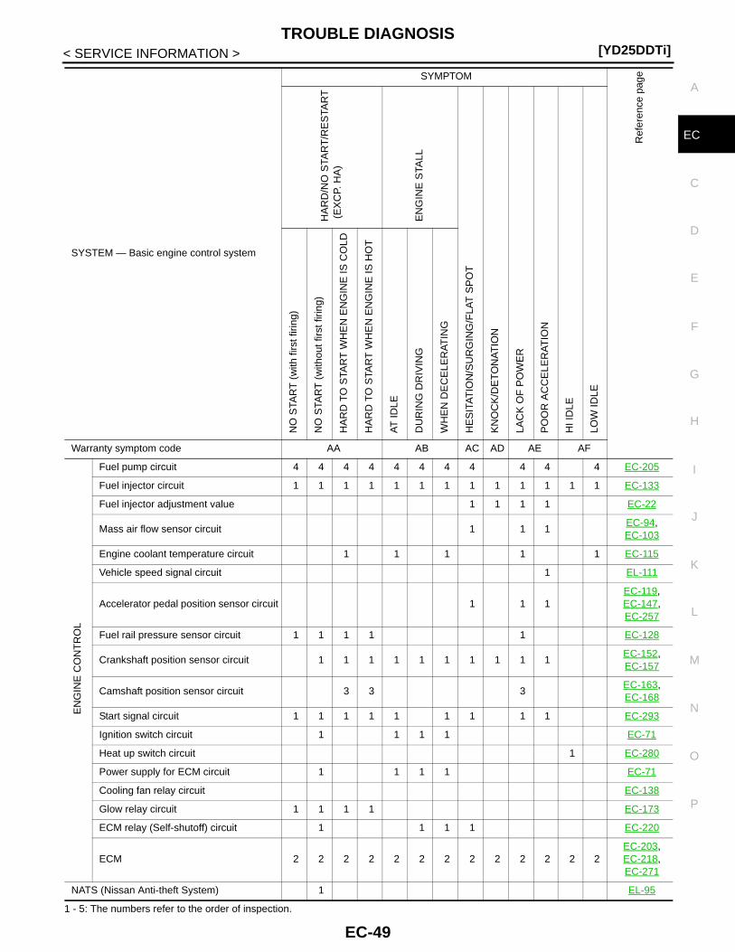
TROUBLE DIAGNOSIS[YD25DDTi]
C
D
E
F
G
H
I
J
K
L
M
A
C
N
P
O
< SERVICE INFORMATION >
E
1 - 5: The numbers refer to the order of inspection.
EN
GIN
E C
ON
TR
OL
Fuel pump circuit 4 4 4 4 4 4 4 4 4 4 4 EC-205
Fuel injector circuit 1 1 1 1 1 1 1 1 1 1 1 1 1 EC-133
Fuel injector adjustment value 1 1 1 1 EC-22
Mass air flow sensor circuit 1 1 1EC-94,EC-103
Engine coolant temperature circuit 1 1 1 1 1 EC-115
Vehicle speed signal circuit 1 EL-111
Accelerator pedal position sensor circuit 1 1 1EC-119,EC-147,EC-257
Fuel rail pressure sensor circuit 1 1 1 1 1 EC-128
Crankshaft position sensor circuit 1 1 1 1 1 1 1 1 1 1EC-152,EC-157
Camshaft position sensor circuit 3 3 3EC-163,EC-168
Start signal circuit 1 1 1 1 1 1 1 1 1 EC-293
Ignition switch circuit 1 1 1 1 EC-71
Heat up switch circuit 1 EC-280
Power supply for ECM circuit 1 1 1 1 EC-71
Cooling fan relay circuit EC-138
Glow relay circuit 1 1 1 1 EC-173
ECM relay (Self-shutoff) circuit 1 1 1 1 EC-220
ECM 2 2 2 2 2 2 2 2 2 2 2 2 2EC-203,EC-218,EC-271
NATS (Nissan Anti-theft System) 1 EL-95
SYSTEM — Basic engine control system
SYMPTOM
Ref
eren
ce p
age
HA
RD
/NO
STA
RT
/RE
STA
RT
(E
XC
P. H
A)
EN
GIN
E S
TALL
HE
SIT
AT
ION
/SU
RG
ING
/FLA
T S
PO
T
KN
OC
K/D
ET
ON
AT
ION
LAC
K O
F P
OW
ER
PO
OR
AC
CE
LER
AT
ION
HI I
DLE
LOW
IDLE
NO
STA
RT
(w
ith fi
rst f
iring
)
NO
STA
RT
(w
ithou
t firs
t firi
ng)
HA
RD
TO
STA
RT
WH
EN
EN
GIN
E IS
CO
LD
HA
RD
TO
STA
RT
WH
EN
EN
GIN
E IS
HO
T
AT
IDLE
DU
RIN
G D
RIV
ING
WH
EN
DE
CE
LER
AT
ING
Warranty symptom code AA AB AC AD AE AF
EC-49
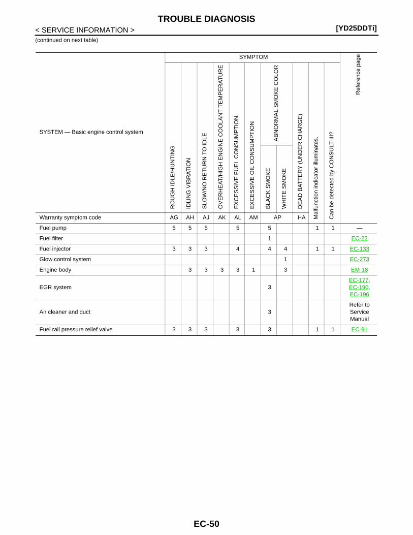
[YD25DDTi]TROUBLE DIAGNOSIS
< SERVICE INFORMATION >(continued on next table)
SYSTEM — Basic engine control system
SYMPTOM
Ref
eren
ce p
age
RO
UG
H ID
LE/H
UN
TIN
G
IDLI
NG
VIB
RA
TIO
N
SLO
W/N
O R
ET
UR
N T
O ID
LE
OV
ER
HE
AT
/HIG
H E
NG
INE
CO
OLA
NT
TE
MP
ER
AT
UR
E
EX
CE
SS
IVE
FU
EL
CO
NS
UM
PT
ION
EX
CE
SS
IVE
OIL
CO
NS
UM
PT
ION
AB
NO
RM
AL
SM
OK
E C
OLO
R
DE
AD
BA
TT
ER
Y (
UN
DE
R C
HA
RG
E)
Mal
func
tion
indi
cato
r ill
umin
ates
.
Can
be
dete
cted
by
CO
NS
ULT
-III?
BLA
CK
SM
OK
E
WH
ITE
SM
OK
E
Warranty symptom code AG AH AJ AK AL AM AP HA
Fuel pump 5 5 5 5 5 1 1 —
Fuel filter 1 EC-22
Fuel injector 3 3 3 4 4 4 1 1 EC-133
Glow control system 1 EC-273
Engine body 3 3 3 3 1 3 EM-18
EGR system 3EC-177,EC-190,EC-196
Air cleaner and duct 3Refer to Service Manual
Fuel rail pressure relief valve 3 3 3 3 3 1 1 EC-91
EC-50

TROUBLE DIAGNOSIS[YD25DDTi]
C
D
E
F
G
H
I
J
K
L
M
A
C
N
P
O
< SERVICE INFORMATION >
E
1 - 5: The numbers refer to the order of inspection.
EN
GIN
E C
ON
TR
OL
Fuel pump circuit 4 4 4 4 1 1 EC-239
Fuel injector circuit 1 1 1 1 1 1 1 1 EC-133
Fuel injector adjustment value 1 1 1 1 1 1 EC-22
Mass air flow sensor circuit 1 1 1EC-94,EC-103
Engine coolant temperature circuit 1 1 1 1 1 1 EC-115
Vehicle speed signal circuit 1 1 EL-111
Accelerator pedal position sensor circuit 1 1 1EC-119,EC-147,EC-257
Fuel rail pressure sensor circuit 1 1 1 EC-128
Crankshaft position sensor circuit 1 1 1 1EC-152,EC-157
Camshaft position sensor circuit 1 1EC-163,EC-168
Start signal circuit EC-293
Ignition switch circuit EC-71
Heat up switch circuit EC-280
Power supply for ECM circuit 1 1 EC-71
Cooling fan relay circuit 2 EC-138
Glow relay circuit 1 EC-173
ECM relay (Self-shutoff) circuit 1 EC-220
ECM 2 2 2 2 2 2 2 2 2 2 2EC-203,EC-218,EC-271
NATS (Nissan Anti-theft System) 1 EL-95
SYSTEM — Basic engine control system
SYMPTOM
Ref
eren
ce p
age
RO
UG
H ID
LE/H
UN
TIN
G
IDLI
NG
VIB
RA
TIO
N
SLO
W/N
O R
ET
UR
N T
O ID
LE
OV
ER
HE
AT
/HIG
H E
NG
INE
CO
OLA
NT
TE
MP
ER
AT
UR
E
EX
CE
SS
IVE
FU
EL
CO
NS
UM
PT
ION
EX
CE
SS
IVE
OIL
CO
NS
UM
PT
ION
AB
NO
RM
AL
SM
OK
E C
OLO
R
DE
AD
BA
TT
ER
Y (
UN
DE
R C
HA
RG
E)
Mal
func
tion
indi
cato
r ill
umin
ates
.
Can
be
dete
cted
by
CO
NS
ULT
-III?
BLA
CK
SM
OK
E
WH
ITE
SM
OK
E
Warranty symptom code AG AH AJ AK AL AM AP HA
EC-51

[YD25DDTi]TROUBLE DIAGNOSIS
< SERVICE INFORMATION >
Engine Control Component Parts Location INFOID:0000000003759326
1. Glow relay 2. Cooling fan motor 3. Engine coolant temperature sensor
4. Mass air flow sensor 5. Camshaft position sensor 6. Glow plug
7. Fuel injector 8. Fuel rail pressure sensor 9. Fuel rail pressure relief valve
10. Fuel Pump 11. EGR volume control valve 12. Fuel filter
1. Fuel pump temperature sensor 2. Fuel pump 3. Fuel rail pressure relief valve
4. Fuel rail pressure sensor
: Vehicle front
JMBIA1284ZZ
JMBIA1286ZZ
EC-52
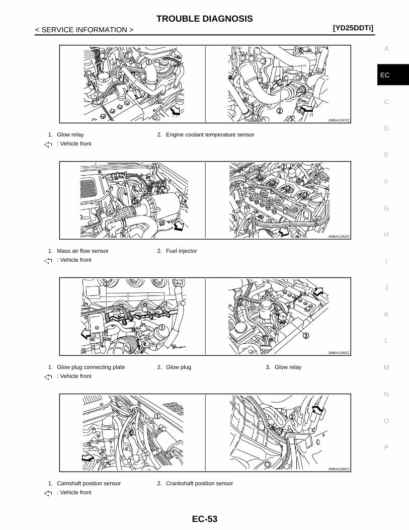
TROUBLE DIAGNOSIS[YD25DDTi]
C
D
E
F
G
H
I
J
K
L
M
A
C
N
P
O
< SERVICE INFORMATION >
E
1. Glow relay 2. Engine coolant temperature sensor
: Vehicle front
1. Mass air flow sensor 2. Fuel injector
: Vehicle front
1. Glow plug connecting plate 2. Glow plug 3. Glow relay
: Vehicle front
1. Camshaft position sensor 2. Crankshaft position sensor
: Vehicle front
JMBIA1287ZZ
JMBIA1290ZZ
JMBIA1289ZZ
JMBIA1288ZZ
EC-53
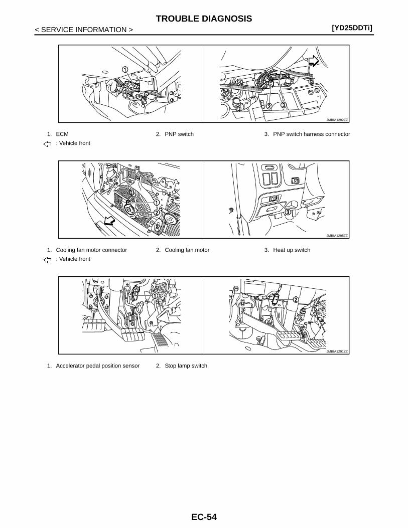
[YD25DDTi]TROUBLE DIAGNOSIS
< SERVICE INFORMATION >
1. ECM 2. PNP switch 3. PNP switch harness connector
: Vehicle front
1. Cooling fan motor connector 2. Cooling fan motor 3. Heat up switch
: Vehicle front
1. Accelerator pedal position sensor 2. Stop lamp switch
JMBIA1292ZZ
JMBIA1295ZZ
JMBIA1291ZZ
EC-54
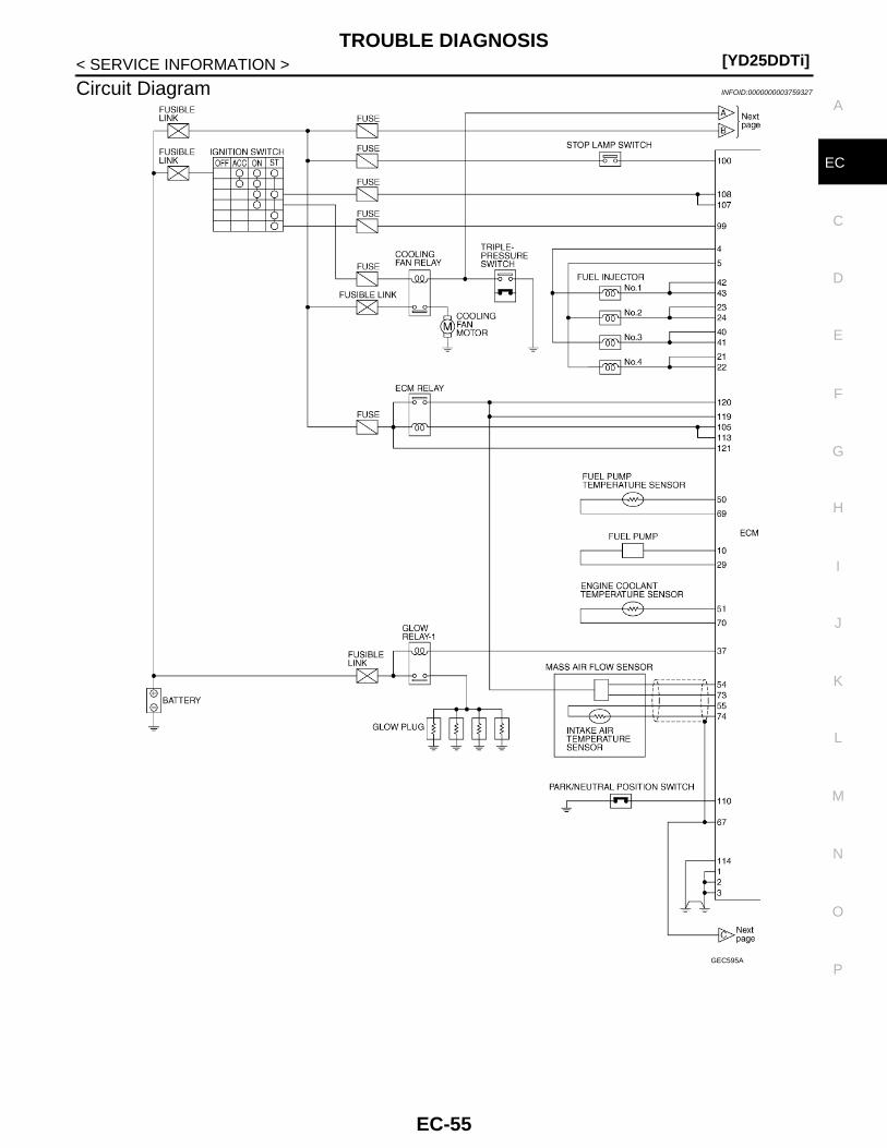
TROUBLE DIAGNOSIS[YD25DDTi]
C
D
E
F
G
H
I
J
K
L
M
A
C
N
P
O
< SERVICE INFORMATION >
E
Circuit Diagram INFOID:0000000003759327
GEC595A
EC-55
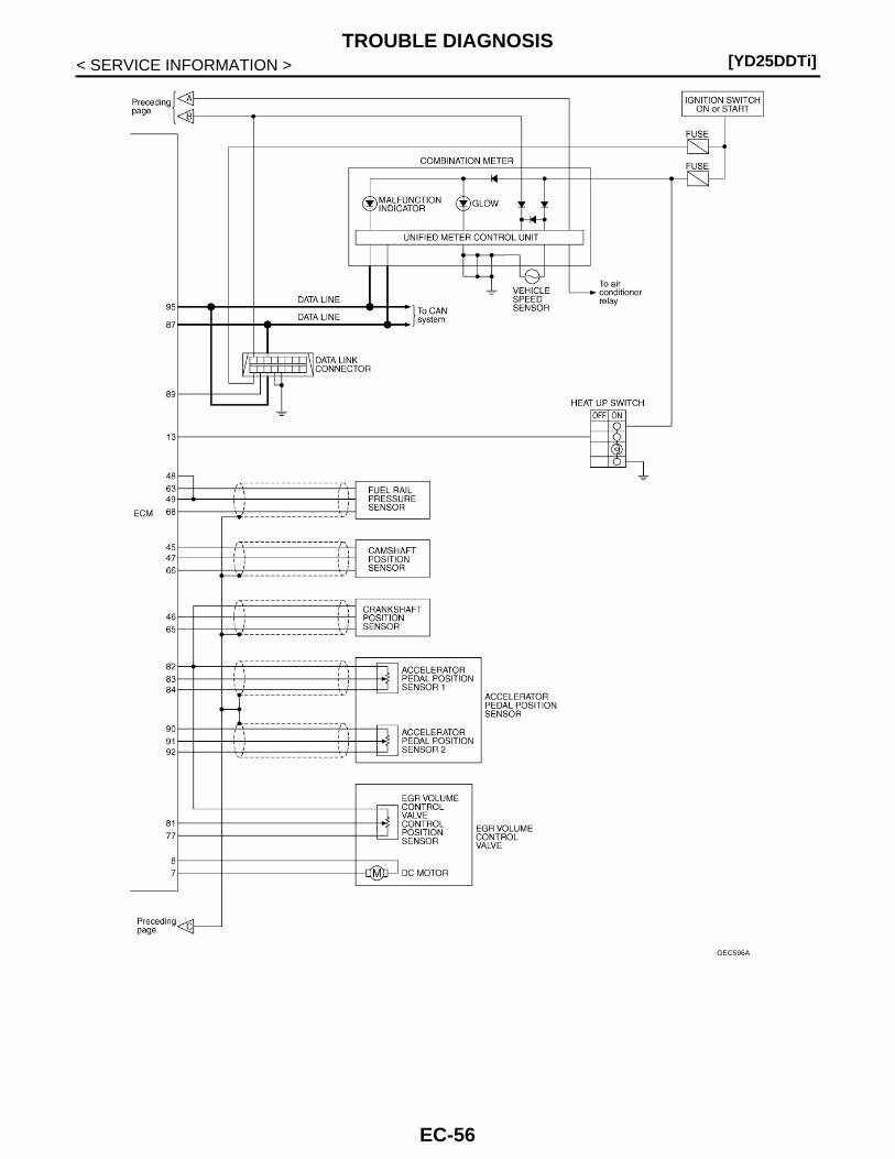
[YD25DDTi]TROUBLE DIAGNOSIS
< SERVICE INFORMATION >
GEC596A
EC-56
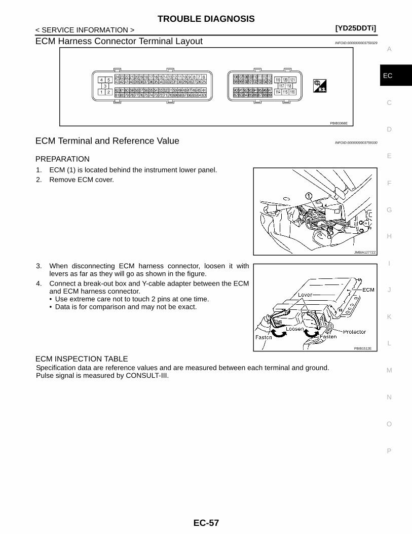
TROUBLE DIAGNOSIS[YD25DDTi]
C
D
E
F
G
H
I
J
K
L
M
A
C
N
P
O
< SERVICE INFORMATION >
E
ECM Harness Connector Terminal Layout INFOID:0000000003759329
ECM Terminal and Reference Value INFOID:0000000003759330
PREPARATION1. ECM (1) is located behind the instrument lower panel.2. Remove ECM cover.
3. When disconnecting ECM harness connector, loosen it withlevers as far as they will go as shown in the figure.
4. Connect a break-out box and Y-cable adapter between the ECMand ECM harness connector.• Use extreme care not to touch 2 pins at one time.• Data is for comparison and may not be exact.
ECM INSPECTION TABLESpecification data are reference values and are measured between each terminal and ground.Pulse signal is measured by CONSULT-III.
PBIB3368E
JMBIA1277ZZ
PBIB1512E
EC-57
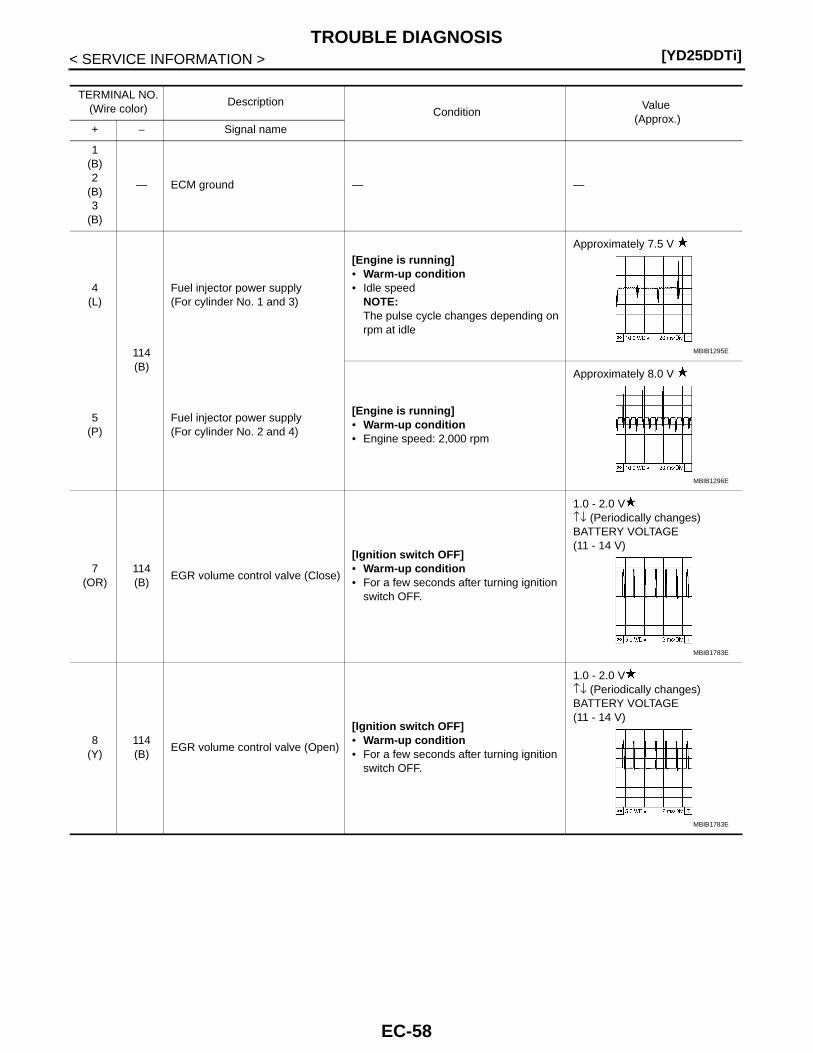
[YD25DDTi]TROUBLE DIAGNOSIS
< SERVICE INFORMATION >
TERMINAL NO.(Wire color)
DescriptionCondition
Value (Approx.)
+ − Signal name
1(B)2
(B)3
(B)
— ECM ground — —
4(L)
114(B)
Fuel injector power supply(For cylinder No. 1 and 3)
[Engine is running]• Warm-up condition• Idle speed
NOTE:The pulse cycle changes depending on rpm at idle
Approximately 7.5 V
5(P)
Fuel injector power supply(For cylinder No. 2 and 4)
[Engine is running]• Warm-up condition• Engine speed: 2,000 rpm
Approximately 8.0 V
7(OR)
114(B)
EGR volume control valve (Close)
[Ignition switch OFF]• Warm-up condition• For a few seconds after turning ignition
switch OFF.
1.0 - 2.0 V↑↓ (Periodically changes)BATTERY VOLTAGE(11 - 14 V)
8(Y)
114(B)
EGR volume control valve (Open)
[Ignition switch OFF]• Warm-up condition• For a few seconds after turning ignition
switch OFF.
1.0 - 2.0 V↑↓ (Periodically changes)BATTERY VOLTAGE(11 - 14 V)
MBIB1295E
MBIB1296E
MBIB1783E
MBIB1783E
EC-58
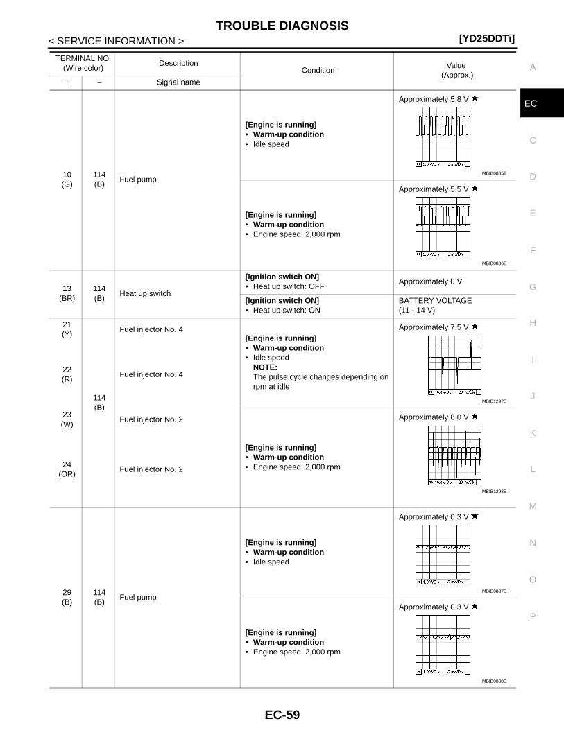
TROUBLE DIAGNOSIS[YD25DDTi]
C
D
E
F
G
H
I
J
K
L
M
A
C
N
P
O
< SERVICE INFORMATION >
E
10(G)
114(B)
Fuel pump
[Engine is running]• Warm-up condition• Idle speed
Approximately 5.8 V
[Engine is running]• Warm-up condition• Engine speed: 2,000 rpm
Approximately 5.5 V
13(BR)
114(B)
Heat up switch
[Ignition switch ON]• Heat up switch: OFF
Approximately 0 V
[Ignition switch ON]• Heat up switch: ON
BATTERY VOLTAGE(11 - 14 V)
21(Y)
114(B)
Fuel injector No. 4[Engine is running]• Warm-up condition• Idle speed
NOTE:The pulse cycle changes depending on rpm at idle
Approximately 7.5 V
22(R)
Fuel injector No. 4
23(W)
Fuel injector No. 2
[Engine is running]• Warm-up condition• Engine speed: 2,000 rpm
Approximately 8.0 V
24(OR)
Fuel injector No. 2
29(B)
114(B)
Fuel pump
[Engine is running]• Warm-up condition• Idle speed
Approximately 0.3 V
[Engine is running]• Warm-up condition• Engine speed: 2,000 rpm
Approximately 0.3 V
TERMINAL NO.(Wire color)
DescriptionCondition
Value (Approx.)
+ − Signal name
MBIB0885E
MBIB0886E
MBIB1297E
MBIB1298E
MBIB0887E
MBIB0888E
EC-59
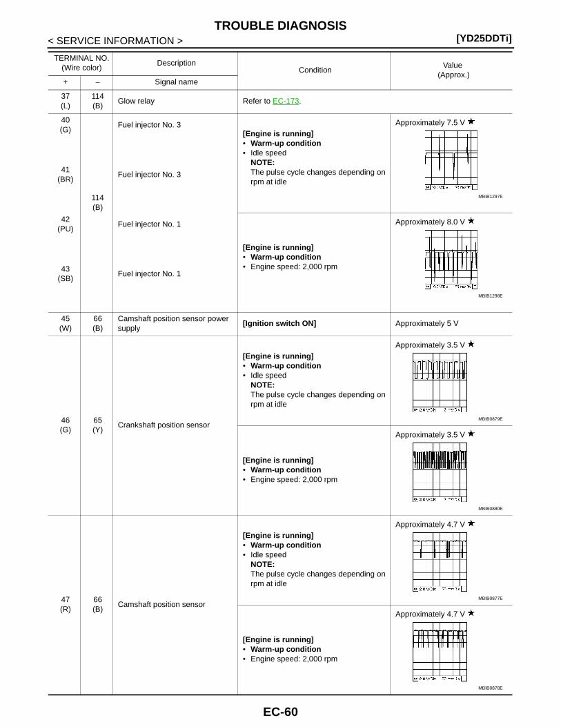
[YD25DDTi]TROUBLE DIAGNOSIS
< SERVICE INFORMATION >
37(L)
114(B)
Glow relay Refer to EC-173.
40(G)
114(B)
Fuel injector No. 3[Engine is running]• Warm-up condition• Idle speed
NOTE:The pulse cycle changes depending on rpm at idle
Approximately 7.5 V
41(BR)
Fuel injector No. 3
42(PU)
Fuel injector No. 1
[Engine is running]• Warm-up condition• Engine speed: 2,000 rpm
Approximately 8.0 V
43(SB)
Fuel injector No. 1
45(W)
66(B)
Camshaft position sensor power supply
[Ignition switch ON] Approximately 5 V
46(G)
65(Y)
Crankshaft position sensor
[Engine is running]• Warm-up condition• Idle speed
NOTE:The pulse cycle changes depending on rpm at idle
Approximately 3.5 V
[Engine is running]• Warm-up condition• Engine speed: 2,000 rpm
Approximately 3.5 V
47(R)
66(B)
Camshaft position sensor
[Engine is running]• Warm-up condition• Idle speed
NOTE:The pulse cycle changes depending on rpm at idle
Approximately 4.7 V
[Engine is running]• Warm-up condition• Engine speed: 2,000 rpm
Approximately 4.7 V
TERMINAL NO.(Wire color)
DescriptionCondition
Value (Approx.)
+ − Signal name
MBIB1297E
MBIB1298E
MBIB0879E
MBIB0880E
MBIB0877E
MBIB0878E
EC-60
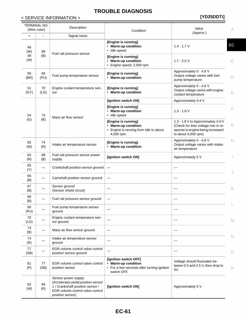
TROUBLE DIAGNOSIS[YD25DDTi]
C
D
E
F
G
H
I
J
K
L
M
A
C
N
P
O
< SERVICE INFORMATION >
E48(W)49(W)
68(B)
Fuel rail pressure sensor
[Engine is running]• Warm-up condition• Idle speed
1.4 - 1.7 V
[Engine is running]• Warm-up condition• Engine speed: 2,000 rpm
1.7 - 2.0 V
50(BR)
69(PU)
Fuel pump temperature sensor[Engine is running]• Warm-up condition
Approximately 0 - 4.8 V Output voltage varies with fuel pump temperature
51(GY)
70(LG)
Engine coolant temperature sen-sor
[Engine is running]• Warm-up condition
Approximately 0 - 4.8 VOutput voltage varies with engine coolant temperature
54(G)
73(B)
Mass air flow sensor
[Ignition switch ON] Approximately 0.4 V
[Engine is running]• Warm-up condition• Idle speed
1.3 - 1.8 V
[Engine is running]• Warm-up condition• Engine is revving from idle to about
4,000 rpm.
1.3 - 1.8 V to Approximately 4.0 V(Check for liner voltage rise in re-sponse to engine being increased to about 4,000 rpm)
55(W)
74(R)
Intake air temperature sensor[Engine is running]• Warm-up condition
Approximately 0 - 4.8 VOutput voltage varies with intake air temperature
63(R)
68(B)
Fuel rail pressure sensor power supply
[Ignition switch ON] Approximately 5 V
65(Y)
— Crankshaft position sensor ground — —
66(B)
— Camshaft position sensor ground — —
67(B)
—Sensor ground(Sensor shield circuit)
— —
68(B)
— Fuel rail pressure sensor ground — —
69(PU)
—Fuel pump temperature sensor ground
— —
70(LG)
—Engine coolant temperature sen-sor ground
— —
73(B)
— Mass air flow sensor ground — —
74(R)
—Intake air temperature sensor ground
— —
77(SB)
—EGR volume control valve control position sensor ground
— —
81(P)
77(SB)
EGR volume control valve control position sensor
[Ignition switch OFF]• Warm-up condition• For a few seconds after turning ignition
switch OFF.
Voltage should fluctuates be-tween 0.5 and 2.5 V, then drop to 0V.
82(W)
84(R)
Sensor power supply(Accelerator pedal position sensor 1 / Crankshaft position sensor / EGR volume control valve control position sensor)
[Ignition switch ON] Approximately 5 V
TERMINAL NO.(Wire color)
DescriptionCondition
Value (Approx.)
+ − Signal name
EC-61

[YD25DDTi]TROUBLE DIAGNOSIS
< SERVICE INFORMATION >
83(B)
84(R)
Accelerator pedal position sensor 1
[Ignition switch ON]• Engine: Stopped• Accelerator pedal: Fully released
0.5 - 1.0 V
[Ignition switch ON]• Engine: Stopped• Accelerator pedal: Fully depressed
3.7 - 4.7 V
84(R)
—Accelerator pedal position sensor 1 ground
— —
87(P)
— CAN communication line — —
89(LG)
114(B)
Data link connector — —
90(L)
92(Y)
Accelerator pedal position sensor 2 power supply
[Ignition switch ON] Approximately 5 V
91(G)
92(Y)
Accelerator pedal position sensor 2
[Ignition switch ON]• Engine: Stopped• Accelerator pedal: Fully released
0.15 - 0.6 V
[Ignition switch ON]• Engine: Stopped• Accelerator pedal: Fully depressed
1.85 - 2.4 V
92(Y)
—Accelerator pedal position sensor 2 ground
— —
95(L)
— CAN communication line — —
99(R)
114(B)
Start signal
[Ignition switch ON] Approximately 0 V
[Ignition switch START]BATTERY VOLTAGE(11 - 14 V)
100(GY)
114(B)
Stop lamp switch
[Ignition switch OFF]• Brake pedal: Fully released
Approximately 0 V
[Ignition switch OFF]• Brake pedal: Slightly depressed
BATTERY VOLTAGE(11 - 14 V)
105(G)
114(B)
ECM relay (self shut-off)
[Ignition switch ON][Ignition switch OFF]• For a few seconds after turning ignition
switch OFF
0 - 1.0 V
[Ignition switch OFF]• More than a few seconds after turning
ignition switch OFF
BATTERY VOLTAGE(11 - 14 V)
107(L)108(L)
114(B)
Ignition switch [Ignition switch ON]BATTERY VOLTAGE(11 - 14 V)
110(BR)
114(B)
Park/neutral position switch
[Ignition switch ON]• Shift lever: Neutral
Approximately 0 V
[Ignition switch ON]• Except the above position
BATTERY VOLTAGE(11 - 14 V)
113(G)
114(B)
ECM relay (self shut-off)
[Ignition switch ON][Ignition switch OFF]• For a few seconds after turning ignition
switch OFF
0 - 1.0 V
[Ignition switch OFF]• More than a few seconds after turning
ignition switch OFF
BATTERY VOLTAGE(11 - 14 V)
TERMINAL NO.(Wire color)
DescriptionCondition
Value (Approx.)
+ − Signal name
EC-62
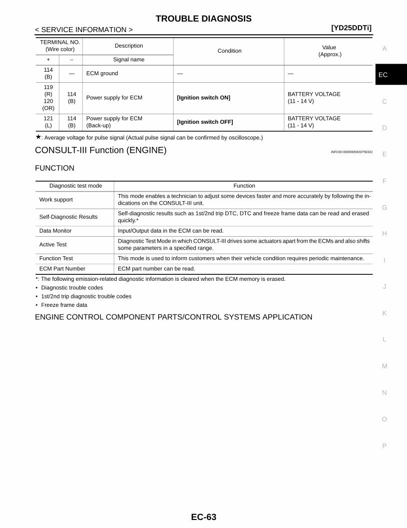
TROUBLE DIAGNOSIS[YD25DDTi]
C
D
E
F
G
H
I
J
K
L
M
A
C
N
P
O
< SERVICE INFORMATION >
E
: Average voltage for pulse signal (Actual pulse signal can be confirmed by oscilloscope.)
CONSULT-III Function (ENGINE) INFOID:0000000003759331
FUNCTION
*: The following emission-related diagnostic information is cleared when the ECM memory is erased.
• Diagnostic trouble codes
• 1st/2nd trip diagnostic trouble codes
• Freeze frame data
ENGINE CONTROL COMPONENT PARTS/CONTROL SYSTEMS APPLICATION
114(B)
— ECM ground — —
119(R)120(OR)
114(B)
Power supply for ECM [Ignition switch ON]BATTERY VOLTAGE(11 - 14 V)
121(L)
114(B)
Power supply for ECM(Back-up)
[Ignition switch OFF]BATTERY VOLTAGE(11 - 14 V)
TERMINAL NO.(Wire color)
DescriptionCondition
Value (Approx.)
+ − Signal name
Diagnostic test mode Function
Work supportThis mode enables a technician to adjust some devices faster and more accurately by following the in-dications on the CONSULT-III unit.
Self-Diagnostic ResultsSelf-diagnostic results such as 1st/2nd trip DTC, DTC and freeze frame data can be read and erased quickly.*
Data Monitor Input/Output data in the ECM can be read.
Active TestDiagnostic Test Mode in which CONSULT-III drives some actuators apart from the ECMs and also shifts some parameters in a specified range.
Function Test This mode is used to inform customers when their vehicle condition requires periodic maintenance.
ECM Part Number ECM part number can be read.
EC-63

[YD25DDTi]TROUBLE DIAGNOSIS
< SERVICE INFORMATION >
X: Applicable
*: This item includes 1st/2nd trip DTCs.
WORK SUPPORT MODE
Work Item
SELF-DIAGNOSTIC MODE
Item
DIAGNOSTIC TEST MODE
SELF-DIAG RESULTSDATA
MONITORACTIVE TESTDTC*
FREEZE FRAME DATA
EN
GIN
E C
ON
TR
OL
CO
MP
ON
EN
T P
AR
TS
INPUT
Crankshaft position sensor × × ×
Camshaft position sensor ×
Engine coolant temperature sensor × × × ×
Vehicle speed sensor × × ×
Fuel pump temperature sensor × × ×
Accelerator pedal position sensor 1 × ×
Accelerator pedal position sensor 2 × ×
Fuel rail pressure sensor × ×
Mass air flow sensor × × ×
Intake air temperature sensor × ×
Battery voltage × ×
Park/neutral position (PNP) switch × ×
EGR volume control valve control position sensor × ×
Stop lamp switch × ×
Heat up switch ×
Ignition switch (Start signal) ×
Air conditioner switch signal ×
Barometric pressure sensor (built-into ECM) × ×
OUTPUT
Fuel pump × × ×
Fuel injector × × ×
Glow relay × × ×
Cooling fan relay × × ×
EGR volume control valve × × ×
WORK ITEM DESCRIPTION USAGE
ENTER INJCTR CALIB DATA • Injector adjustment value is written onto ECM memory. When performing Injector Adjust-ment Value Registration.
EGR/V LEARN CLR• EGR volume control valve learning value stored in ECM is
cleared.
EGR volume control valve closed position learning value should be cleared under the following cases.• EGR volume control valve is re-
moved.• EGR volume control valve is re-
placed.
INJ ADJ VAL CLR • Injector adjustment value stored in ECM is initialized. Before changing injector adjust-ment value stored in ECM, it is recommended to perform this work item.
EC-64
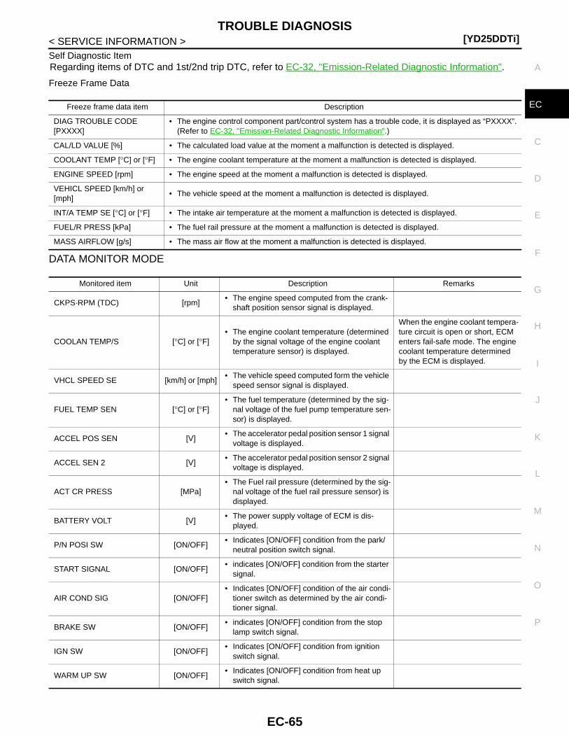
TROUBLE DIAGNOSIS[YD25DDTi]
C
D
E
F
G
H
I
J
K
L
M
A
C
N
P
O
< SERVICE INFORMATION >
E
Self Diagnostic ItemRegarding items of DTC and 1st/2nd trip DTC, refer to EC-32, "Emission-Related Diagnostic Information".
Freeze Frame Data
DATA MONITOR MODE
Freeze frame data item Description
DIAG TROUBLE CODE[PXXXX]
• The engine control component part/control system has a trouble code, it is displayed as “PXXXX”. (Refer to EC-32, "Emission-Related Diagnostic Information".)
CAL/LD VALUE [%] • The calculated load value at the moment a malfunction is detected is displayed.
COOLANT TEMP [°C] or [°F] • The engine coolant temperature at the moment a malfunction is detected is displayed.
ENGINE SPEED [rpm] • The engine speed at the moment a malfunction is detected is displayed.
VEHICL SPEED [km/h] or [mph]
• The vehicle speed at the moment a malfunction is detected is displayed.
INT/A TEMP SE [°C] or [°F] • The intake air temperature at the moment a malfunction is detected is displayed.
FUEL/R PRESS [kPa] • The fuel rail pressure at the moment a malfunction is detected is displayed.
MASS AIRFLOW [g/s] • The mass air flow at the moment a malfunction is detected is displayed.
Monitored item Unit Description Remarks
CKPS·RPM (TDC) [rpm]• The engine speed computed from the crank-
shaft position sensor signal is displayed.
COOLAN TEMP/S [°C] or [°F]• The engine coolant temperature (determined
by the signal voltage of the engine coolant temperature sensor) is displayed.
When the engine coolant tempera-ture circuit is open or short, ECM enters fail-safe mode. The engine coolant temperature determined by the ECM is displayed.
VHCL SPEED SE [km/h] or [mph]• The vehicle speed computed form the vehicle
speed sensor signal is displayed.
FUEL TEMP SEN [°C] or [°F]• The fuel temperature (determined by the sig-
nal voltage of the fuel pump temperature sen-sor) is displayed.
ACCEL POS SEN [V]• The accelerator pedal position sensor 1 signal
voltage is displayed.
ACCEL SEN 2 [V]• The accelerator pedal position sensor 2 signal
voltage is displayed.
ACT CR PRESS [MPa]• The Fuel rail pressure (determined by the sig-
nal voltage of the fuel rail pressure sensor) is displayed.
BATTERY VOLT [V]• The power supply voltage of ECM is dis-
played.
P/N POSI SW [ON/OFF]• Indicates [ON/OFF] condition from the park/
neutral position switch signal.
START SIGNAL [ON/OFF]• indicates [ON/OFF] condition from the starter
signal.
AIR COND SIG [ON/OFF]• Indicates [ON/OFF] condition of the air condi-
tioner switch as determined by the air condi-tioner signal.
BRAKE SW [ON/OFF]• indicates [ON/OFF] condition from the stop
lamp switch signal.
IGN SW [ON/OFF]• Indicates [ON/OFF] condition from ignition
switch signal.
WARM UP SW [ON/OFF]• Indicates [ON/OFF] condition from heat up
switch signal.
EC-65
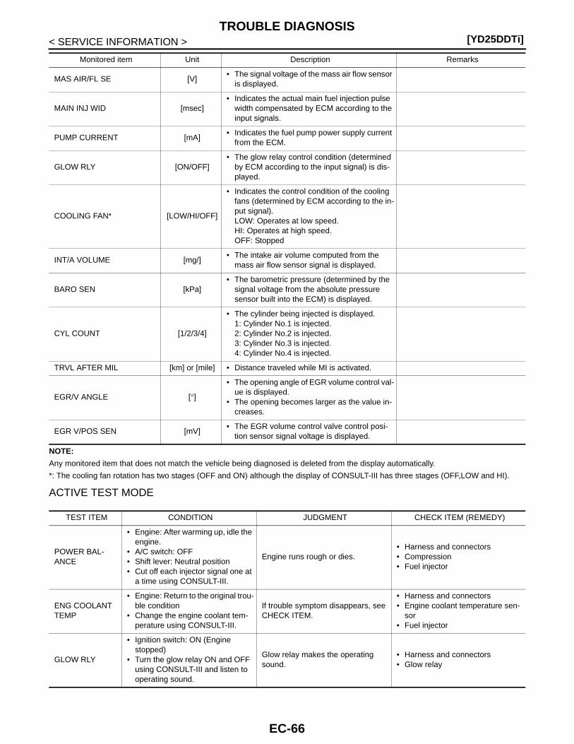
[YD25DDTi]TROUBLE DIAGNOSIS
< SERVICE INFORMATION >
NOTE:
Any monitored item that does not match the vehicle being diagnosed is deleted from the display automatically.
*: The cooling fan rotation has two stages (OFF and ON) although the display of CONSULT-III has three stages (OFF,LOW and HI).
ACTIVE TEST MODE
MAS AIR/FL SE [V]• The signal voltage of the mass air flow sensor
is displayed.
MAIN INJ WID [msec]• Indicates the actual main fuel injection pulse
width compensated by ECM according to the input signals.
PUMP CURRENT [mA]• Indicates the fuel pump power supply current
from the ECM.
GLOW RLY [ON/OFF]• The glow relay control condition (determined
by ECM according to the input signal) is dis-played.
COOLING FAN* [LOW/HI/OFF]
• Indicates the control condition of the cooling fans (determined by ECM according to the in-put signal).LOW: Operates at low speed.HI: Operates at high speed.OFF: Stopped
INT/A VOLUME [mg/]• The intake air volume computed from the
mass air flow sensor signal is displayed.
BARO SEN [kPa]• The barometric pressure (determined by the
signal voltage from the absolute pressure sensor built into the ECM) is displayed.
CYL COUNT [1/2/3/4]
• The cylinder being injected is displayed.1: Cylinder No.1 is injected.2: Cylinder No.2 is injected.3: Cylinder No.3 is injected.4: Cylinder No.4 is injected.
TRVL AFTER MIL [km] or [mile] • Distance traveled while MI is activated.
EGR/V ANGLE [°]
• The opening angle of EGR volume control val-ue is displayed.
• The opening becomes larger as the value in-creases.
EGR V/POS SEN [mV]• The EGR volume control valve control posi-
tion sensor signal voltage is displayed.
Monitored item Unit Description Remarks
TEST ITEM CONDITION JUDGMENT CHECK ITEM (REMEDY)
POWER BAL-ANCE
• Engine: After warming up, idle the engine.
• A/C switch: OFF• Shift lever: Neutral position• Cut off each injector signal one at
a time using CONSULT-III.
Engine runs rough or dies.• Harness and connectors• Compression• Fuel injector
ENG COOLANT TEMP
• Engine: Return to the original trou-ble condition
• Change the engine coolant tem-perature using CONSULT-III.
If trouble symptom disappears, see CHECK ITEM.
• Harness and connectors• Engine coolant temperature sen-
sor• Fuel injector
GLOW RLY
• Ignition switch: ON (Engine stopped)
• Turn the glow relay ON and OFF using CONSULT-III and listen to operating sound.
Glow relay makes the operating sound.
• Harness and connectors• Glow relay
EC-66
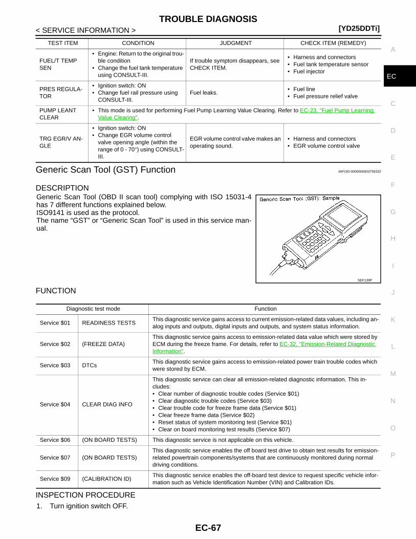
TROUBLE DIAGNOSIS[YD25DDTi]
C
D
E
F
G
H
I
J
K
L
M
A
C
N
P
O
< SERVICE INFORMATION >
E
Generic Scan Tool (GST) Function INFOID:0000000003759332
DESCRIPTIONGeneric Scan Tool (OBD II scan tool) complying with ISO 15031-4has 7 different functions explained below.ISO9141 is used as the protocol.The name “GST” or “Generic Scan Tool” is used in this service man-ual.
FUNCTION
INSPECTION PROCEDURE1. Turn ignition switch OFF.
FUEL/T TEMP SEN
• Engine: Return to the original trou-ble condition
• Change the fuel tank temperature using CONSULT-III.
If trouble symptom disappears, see CHECK ITEM.
• Harness and connectors• Fuel tank temperature sensor• Fuel injector
PRES REGULA-TOR
• Ignition switch: ON• Change fuel rail pressure using
CONSULT-III.Fuel leaks.
• Fuel line• Fuel pressure relief valve
PUMP LEANT CLEAR
• This mode is used for performing Fuel Pump Learning Value Clearing. Refer to EC-23, "Fuel Pump Learning Value Clearing".
TRG EGR/V AN-GLE
• Ignition switch: ON• Change EGR volume control
valve opening angle (within the range of 0 - 70°) using CONSULT-III.
EGR volume control valve makes an operating sound.
• Harness and connectors• EGR volume control valve
TEST ITEM CONDITION JUDGMENT CHECK ITEM (REMEDY)
SEF139P
Diagnostic test mode Function
Service $01 READINESS TESTSThis diagnostic service gains access to current emission-related data values, including an-alog inputs and outputs, digital inputs and outputs, and system status information.
Service $02 (FREEZE DATA)This diagnostic service gains access to emission-related data value which were stored by ECM during the freeze frame. For details, refer to EC-32, "Emission-Related Diagnostic Information".
Service $03 DTCsThis diagnostic service gains access to emission-related power train trouble codes which were stored by ECM.
Service $04 CLEAR DIAG INFO
This diagnostic service can clear all emission-related diagnostic information. This in-cludes:• Clear number of diagnostic trouble codes (Service $01)• Clear diagnostic trouble codes (Service $03)• Clear trouble code for freeze frame data (Service $01)• Clear freeze frame data (Service $02)• Reset status of system monitoring test (Service $01)• Clear on board monitoring test results (Service $07)
Service $06 (ON BOARD TESTS) This diagnostic service is not applicable on this vehicle.
Service $07 (ON BOARD TESTS)This diagnostic service enables the off board test drive to obtain test results for emission-related powertrain components/systems that are continuously monitored during normal driving conditions.
Service $09 (CALIBRATION ID)This diagnostic service enables the off-board test device to request specific vehicle infor-mation such as Vehicle Identification Number (VIN) and Calibration IDs.
EC-67

[YD25DDTi]TROUBLE DIAGNOSIS
< SERVICE INFORMATION >2. Connect “GST” to data link connector (1), which is located under
drivers side dash panel.3. Turn ignition switch ON.
4. Enter the program according to instruction on the screen or inthe operation manual.
(*: Regarding GST screens in this section, sample screens areshown.)
5. Perform each diagnostic mode according to each service proce-dure.
For further information, see the GST Operation Manual of thetool maker.
CONSULT-III Reference Value in Data Monitor Mode INFOID:0000000003759333
Remarks:l Specification data are reference values.l Specification data are output/input values which are detected or supplied by the ECM at the connector.* Specification data may not be directly related to their components signals/values/operations.
JMBIA1296ZZ
SEF398S
SEF416S
MONITOR ITEM CONDITION SPECIFICATION
CKPS-RPM (TDC)• Run engine and compare CONSULT-III value with the tachometer in-
dication.Almost the same speed as the ta-chometer indication
COOLAN TEMP/S • Engine: After warming up More than 70°C (158°F)
VHCL SPEED SE• Turn drive wheels and compare CONSULT-III value with the speed-
ometer indicationAlmost the same speed as the speed-ometer indication
FUEL TEMP SEN • Engine: After warming up More than 40°C (104°F)
ACCEL POS SEN*1 • Ignition switch: ON(Engine stopped)
Accelerator pedal: Fully released 0.5 - 1.0 V
Accelerator pedal: Fully depressed 4.0 - 4.8 V
ACCEL SEN 2*1 • Ignition switch: ON(Engine stopped)
Accelerator pedal: Fully released 0.3 - 1.2 V
Accelerator pedal: Fully depressed 3.7 - 4.8 V
ACT CR PRESS
• Engine: After warming up• Air conditioner switch: OFF• Shift lever: Neutral• No load
Idle 25 - 35 MPa
2,000 rpm 50 - 60 MPa
EC-68

TROUBLE DIAGNOSIS[YD25DDTi]
C
D
E
F
G
H
I
J
K
L
M
A
C
N
P
O
< SERVICE INFORMATION >
E
NOTE:
Any monitored item that does not match the vehicle being diagnosed is deleted from the display automatically.
*1: This signal is converted by ECM internally. Thus, this differs from ECM terminals voltage.
*2: The cooling fan rotation has two stages (OFF and ON) although the display of CONSULT-III has three stages (OFF,LOW and HI).
BATTERY VOLT • Ignition switch: ON (Engine stopped) 11 - 14 V
P/N POSI SW • Ignition switch: ONShift lever: Neutral ON
Except above OFF
START SIGNAL • Ignition switch: ON → START → ON OFF → ON → OFF
AIR COND SIG• Engine: After warming up, idle
the engine
Air conditioner switch: OFF OFF
Air conditioner switch: ON(Compressor operates.)
ON
BRAKE SW • Ignition switch: ONBrake pedal: Fully released OFF
Brake pedal: Slightly depressed ON
IGN SW • Ignition switch: ON → OFF ON → OFF
WARM UP SW • Ignition switch: ONHeat up switch: OFF OFF
Heat up switch: ON ON
MAS AIR/FL SE*1
• Engine: After warming up • Air conditioner switch: OFF• Shift lever: Neutral• No load
Ignition switch: ON (Engine stopped)
Approximately 0.4 V
Idle 1.3 - 1.8 V
Engine is revving from idle to about 4,000 rpm.
1.3 - 1.8 V to Approximately 4.0 V(Check for liner voltage rise in re-sponse to engine being increased to about 4,000 rpm)
MAIN INJ WID• Engine: After warming up• Shift lever: Neutral• Idle speed
No load 0.50 - 0.70 msec
Blower fan switch: ON 0.50 - 0.80 msec
PUMP CURRENT
• Engine: After warming up• Air conditioner switch: OFF• Shift lever: Neutral• No load
Idle 1,600 - 2,000 mA
2,000 rpm 1,500 - 1,900 mA
GLOW RLY Refer to EC-273.
COOLING FAN*2
• When cooling fan is stopped. OFF
• When cooling fans operate at low speed. LOW
• When cooling fans operate at high speed. HI
INT/A VOLUME • Engine: After warming up, idle the engine 150 - 450 mg/
BARO SEN • Ignition switch: ON
AltitudeApprox. 0m: Approx. 100.62 kPa
(1.0062 bar, 1.026 kg/cm2, 14.59 psi)Approx. 1,000 m: Approx. 88.95 kPa
(0.8895 bar, 0.907 kg/cm2, 12.90 psi)Approx. 1,500 m: Approx. 83.16 kPa
(0.8316 bar, 0.848 kg/cm2, 12.06 psi)Approx. 2,000 m: Approx. 78.36 kPa
(0.7836 bar, 0.799 kg/cm2, 11.36 psi)
CYL COUNT • Engine is running 1 → 3 → 4 → 2
TRVL AFTER MIL • Ignition switch: ONVehicle has traveled after MI has turned ON.
0 - 65,535 km(0 - 40,723 mile)
EGR/V ANGLE • Ignition switch: ON (Engine stopped) Approx. 0°
EGR V/POS SEN • Ignition switch: ON (Engine stopped) 1,050 - 1,350 mV
MONITOR ITEM CONDITION SPECIFICATION
EC-69
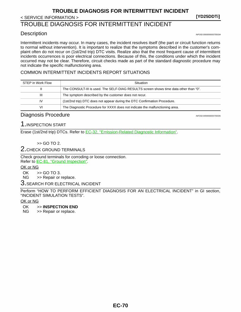
[YD25DDTi]TROUBLE DIAGNOSIS FOR INTERMITTENT INCIDENT
< SERVICE INFORMATION >
TROUBLE DIAGNOSIS FOR INTERMITTENT INCIDENT
Description INFOID:0000000003759334
Intermittent incidents may occur. In many cases, the incident resolves itself (the part or circuit function returnsto normal without intervention). It is important to realize that the symptoms described in the customer's com-plaint often do not recur on (1st/2nd trip) DTC visits. Realize also that the most frequent cause of intermittentincidents occurrences is poor electrical connections. Because of this, the conditions under which the incidentoccurred may not be clear. Therefore, circuit checks made as part of the standard diagnostic procedure maynot indicate the specific malfunctioning area.
COMMON INTERMITTENT INCIDENTS REPORT SITUATIONS
Diagnosis Procedure INFOID:0000000003759335
1.INSPECTION START
Erase (1st/2nd trip) DTCs. Refer to EC-32, "Emission-Related Diagnostic Information".
>> GO TO 2.
2.CHECK GROUND TERMINALS
Check ground terminals for corroding or loose connection.Refer to EC-81, "Ground Inspection".OK or NGOK >> GO TO 3.NG >> Repair or replace.
3.SEARCH FOR ELECTRICAL INCIDENT
Perform “HOW TO PERFORM EFFICIENT DIAGNOSIS FOR AN ELECTRICAL INCIDENT” in GI section,“INCIDENT SIMULATION TESTS”.OK or NGOK >> INSPECTION ENDNG >> Repair or replace.
STEP in Work Flow Situation
II The CONSULT-III is used. The SELF-DIAG RESULTS screen shows time data other than “0”.
III The symptom described by the customer does not recur.
IV (1st/2nd trip) DTC does not appear during the DTC Confirmation Procedure.
VI The Diagnostic Procedure for XXXX does not indicate the malfunctioning area.
EC-70

POWER SUPPLY AND GROUND CIRCUIT[YD25DDTi]
C
D
E
F
G
H
I
J
K
L
M
A
C
N
P
O
< SERVICE INFORMATION >
E
POWER SUPPLY AND GROUND CIRCUIT
Wiring Diagram INFOID:0000000003759336
LHD MODELS
Specification data are reference values and are measured between each terminal and ground.
GEC597A
EC-71

[YD25DDTi]POWER SUPPLY AND GROUND CIRCUIT
< SERVICE INFORMATION >
TERMINAL NO.(Wire color)
DescriptionCondition
Value (Approx.)
+ − Signal name
105(G)
114(B)
ECM relay (self shut-off)
[Ignition switch ON][Ignition switch OFF]• For a few seconds after turning ignition
switch OFF
0 - 1.0 V
[Ignition switch OFF]• More than a few seconds after turning
ignition switch OFF
BATTERY VOLTAGE(11 - 14 V)
107(L)108(L)
114(B)
Ignition switch [Ignition switch ON]BATTERY VOLTAGE(11 - 14 V)
113(G)
114(B)
ECM relay (self shut-off)
[Ignition switch ON][Ignition switch OFF]• For a few seconds after turning ignition
switch OFF
0 - 1.0 V
[Ignition switch OFF]• More than a few seconds after turning
ignition switch OFF
BATTERY VOLTAGE(11 - 14 V)
119(R)120(OR)
114(B)
Power supply for ECM [Ignition switch ON]BATTERY VOLTAGE(11 - 14 V)
121(L)
114(B)
Power supply for ECM(Back-up)
[Ignition switch OFF]BATTERY VOLTAGE(11 - 14 V)
EC-72
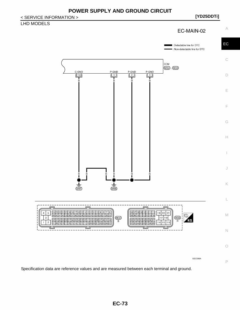
POWER SUPPLY AND GROUND CIRCUIT[YD25DDTi]
C
D
E
F
G
H
I
J
K
L
M
A
C
N
P
O
< SERVICE INFORMATION >
E
LHD MODELS
Specification data are reference values and are measured between each terminal and ground.
GEC598A
EC-73
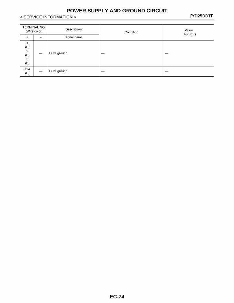
[YD25DDTi]POWER SUPPLY AND GROUND CIRCUIT
< SERVICE INFORMATION >
TERMINAL NO.(Wire color)
DescriptionCondition
Value (Approx.)
+ − Signal name
1(B)2
(B)3
(B)
— ECM ground — —
114(B)
— ECM ground — —
EC-74
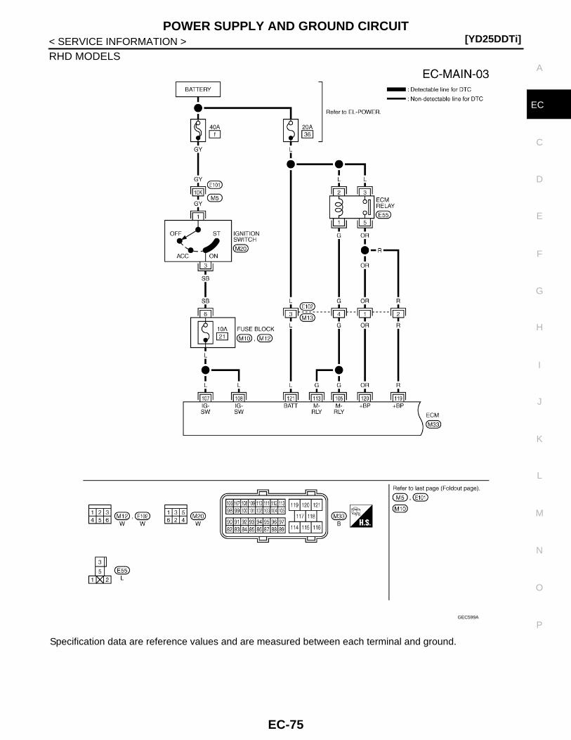
POWER SUPPLY AND GROUND CIRCUIT[YD25DDTi]
C
D
E
F
G
H
I
J
K
L
M
A
C
N
P
O
< SERVICE INFORMATION >
E
RHD MODELS
Specification data are reference values and are measured between each terminal and ground.
GEC599A
EC-75
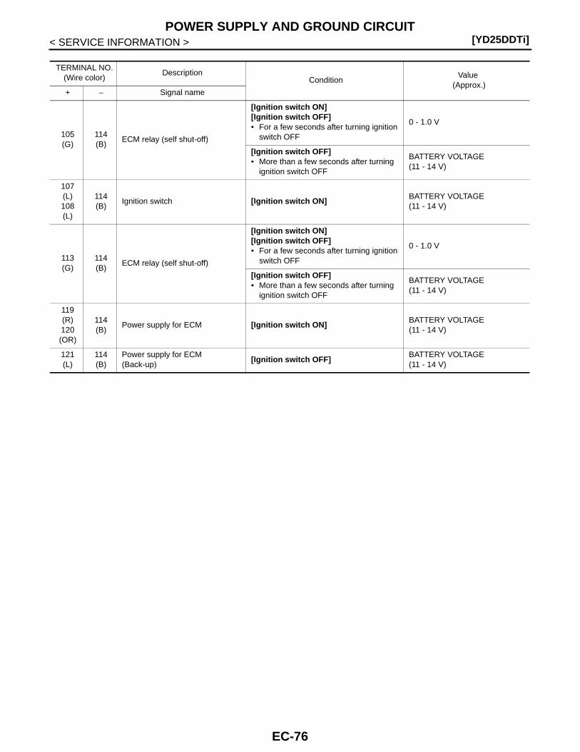
[YD25DDTi]POWER SUPPLY AND GROUND CIRCUIT
< SERVICE INFORMATION >
TERMINAL NO.(Wire color)
DescriptionCondition
Value (Approx.)
+ − Signal name
105(G)
114(B)
ECM relay (self shut-off)
[Ignition switch ON][Ignition switch OFF]• For a few seconds after turning ignition
switch OFF
0 - 1.0 V
[Ignition switch OFF]• More than a few seconds after turning
ignition switch OFF
BATTERY VOLTAGE(11 - 14 V)
107(L)108(L)
114(B)
Ignition switch [Ignition switch ON]BATTERY VOLTAGE(11 - 14 V)
113(G)
114(B)
ECM relay (self shut-off)
[Ignition switch ON][Ignition switch OFF]• For a few seconds after turning ignition
switch OFF
0 - 1.0 V
[Ignition switch OFF]• More than a few seconds after turning
ignition switch OFF
BATTERY VOLTAGE(11 - 14 V)
119(R)120(OR)
114(B)
Power supply for ECM [Ignition switch ON]BATTERY VOLTAGE(11 - 14 V)
121(L)
114(B)
Power supply for ECM(Back-up)
[Ignition switch OFF]BATTERY VOLTAGE(11 - 14 V)
EC-76

POWER SUPPLY AND GROUND CIRCUIT[YD25DDTi]
C
D
E
F
G
H
I
J
K
L
M
A
C
N
P
O
< SERVICE INFORMATION >
E
RHD MODELS
Specification data are reference values and are measured between each terminal and ground.
GEC600A
EC-77

[YD25DDTi]POWER SUPPLY AND GROUND CIRCUIT
< SERVICE INFORMATION >
Diagnosis Procedure INFOID:0000000003759337
1.CHECK GROUND CONNECTIONS
1. Turn ignition switch OFF.2. Loosen and retighten ground screws on the body.
Refer to EC-82, "Ground Inspection".- Body ground M97 (1)- Body ground M99 (2)- ECM (3)OK or NGOK >> GO TO 2.NG >> Repair or replace ground connections.
2.CHECK ECM GROUND CIRCUIT FOR OPEN AND SHORT
1. Disconnect ECM harness connector.2. Check the continuity between ECM harness connector and ground.
3. Also check harness for short to power.OK or NGOK >> GO TO 3.NG >> Repair open or short to power in harness or connectors.
3.CHECK ECM POWER SUPPLY CIRCUIT-I
1. Reconnect ECM harness connector.2. Turn ignition switch ON.3. Check voltage between ECM connector terminal as follows.
TERMINAL NO.(Wire color)
DescriptionCondition
Value (Approx.)
+ − Signal name
1(B)2
(B)3
(B)
— ECM ground — —
114(B)
— ECM ground — —
JMBIA1299ZZ
ECMGround Continuity
Connector Terminal
M32
1
Ground Existed2
3
M33 114
EC-78
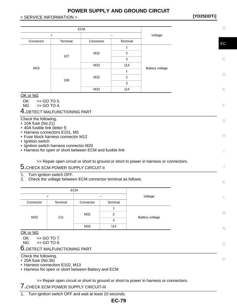
POWER SUPPLY AND GROUND CIRCUIT[YD25DDTi]
C
D
E
F
G
H
I
J
K
L
M
A
C
N
P
O
< SERVICE INFORMATION >
E
OK or NGOK >> GO TO 5.NG >> GO TO 4.
4.DETECT MALFUNCTIONING PART
Check the following.• 10A fuse (No.21)• 40A fusible link (letter f)• Harness connectors E101, M5• Fuse block harness connector M12• Ignition switch• Ignition switch harness connector M20• Harness for open or short between ECM and fusible link
>> Repair open circuit or short to ground or short to power in harness or connectors.
5.CHECK ECM POWER SUPPLY CIRCUIT-II
1. Turn ignition switch OFF.2. Check the voltage between ECM connector terminal as follows.
OK or NGOK >> GO TO 7.NG >> GO TO 6.
6.DETECT MALFUNCTIONING PART
Check the following.• 20A fuse (No.36)• Harness connectors E102, M13• Harness for open or short between Battery and ECM
>> Repair open circuit or short to ground or short to power in harness or connectors.
7.CHECK ECM POWER SUPPLY CIRCUIT-III
1. Turn ignition switch OFF and wait at least 10 seconds.
ECM
Voltage+ –
Connector Terminal Connector Terminal
M33
107M32
1
Battery voltage
2
3
M33 114
108M32
1
2
3
M33 114
ECM
Voltage+ –
Connector Terminal Connector Terminal
M33 121M32
1
Battery voltage2
3
M33 114
EC-79
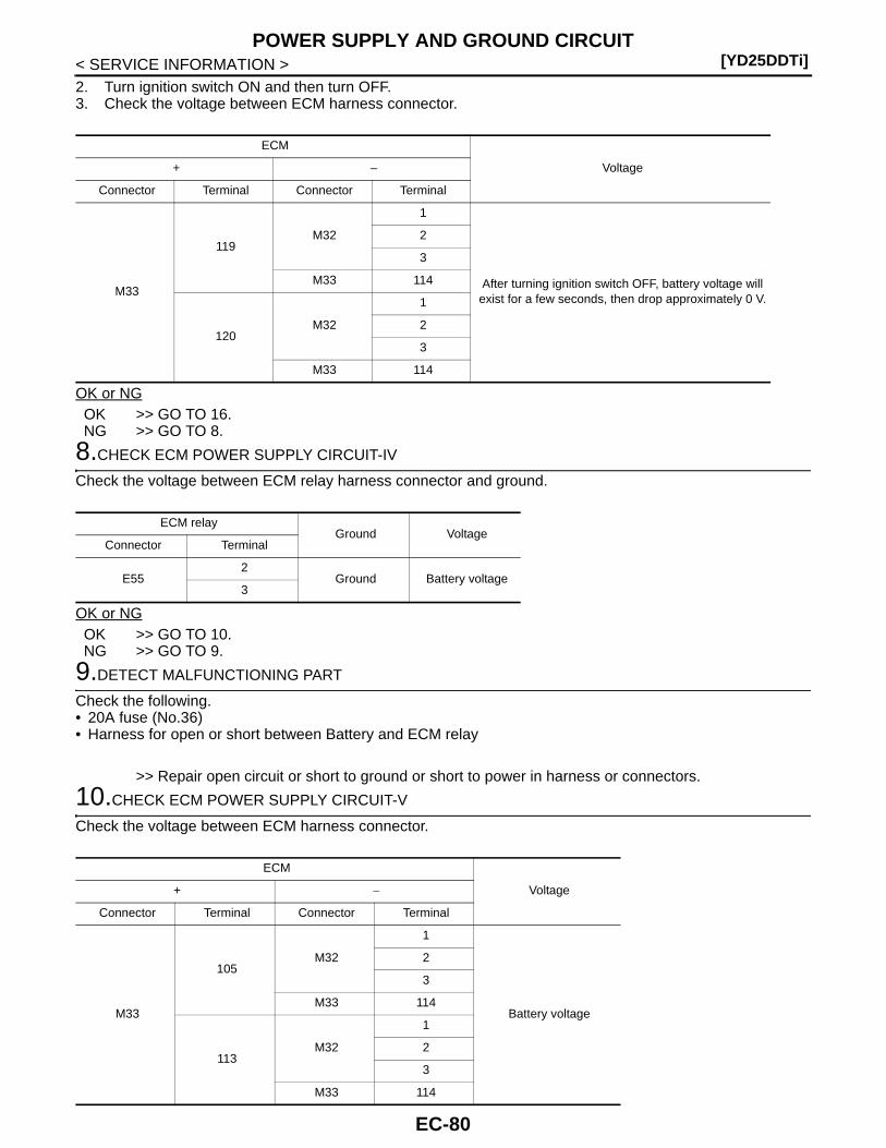
[YD25DDTi]POWER SUPPLY AND GROUND CIRCUIT
< SERVICE INFORMATION >2. Turn ignition switch ON and then turn OFF.3. Check the voltage between ECM harness connector.
OK or NGOK >> GO TO 16.NG >> GO TO 8.
8.CHECK ECM POWER SUPPLY CIRCUIT-IV
Check the voltage between ECM relay harness connector and ground.
OK or NGOK >> GO TO 10.NG >> GO TO 9.
9.DETECT MALFUNCTIONING PART
Check the following.• 20A fuse (No.36)• Harness for open or short between Battery and ECM relay
>> Repair open circuit or short to ground or short to power in harness or connectors.
10.CHECK ECM POWER SUPPLY CIRCUIT-V
Check the voltage between ECM harness connector.
ECM
Voltage+ –
Connector Terminal Connector Terminal
M33
119M32
1
After turning ignition switch OFF, battery voltage will exist for a few seconds, then drop approximately 0 V.
2
3
M33 114
120M32
1
2
3
M33 114
ECM relayGround Voltage
Connector Terminal
E552
Ground Battery voltage3
ECM
Voltage+ −
Connector Terminal Connector Terminal
M33
105M32
1
Battery voltage
2
3
M33 114
113M32
1
2
3
M33 114
EC-80
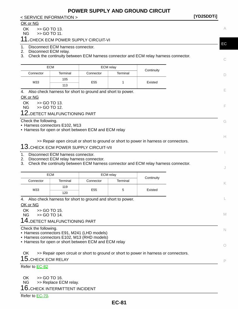
POWER SUPPLY AND GROUND CIRCUIT[YD25DDTi]
C
D
E
F
G
H
I
J
K
L
M
A
C
N
P
O
< SERVICE INFORMATION >
E
OK or NGOK >> GO TO 13.NG >> GO TO 11.
11.CHECK ECM POWER SUPPLY CIRCUIT-VI
1. Disconnect ECM harness connector.2. Disconnect ECM relay.3. Check the continuity between ECM harness connector and ECM relay harness connector.
4. Also check harness for short to ground and short to power.OK or NGOK >> GO TO 13.NG >> GO TO 12.
12.DETECT MALFUNCTIONING PART
Check the following.• Harness connectors E102, M13• Harness for open or short between ECM and ECM relay
>> Repair open circuit or short to ground or short to power in harness or connectors.
13.CHECK ECM POWER SUPPLY CIRCUIT-VII
1. Disconnect ECM harness connector.2. Disconnect ECM relay harness connector.3. Check the continuity between ECM harness connector and ECM relay harness connector.
4. Also check harness for short to ground and short to power.OK or NGOK >> GO TO 15.NG >> GO TO 14.
14.DETECT MALFUNCTIONING PART
Check the following.• Harness connectors E91, M241 (LHD models)• Harness connectors E102, M13 (RHD models)• Harness for open or short between ECM and ECM relay
OK >> Repair open circuit or short to ground or short to power in harness or connectors.
15.CHECK ECM RELAY
Refer to EC-82
OK >> GO TO 16.NG >> Replace ECM relay.
16.CHECK INTERMITTENT INCIDENT
Refer to EC-70.
ECM ECM relayContinuity
Connector Terminal Connector Terminal
M33105
E55 1 Existed113
ECM ECM relayContinuity
Connector Terminal Connector Terminal
M33119
E55 5 Existed120
EC-81
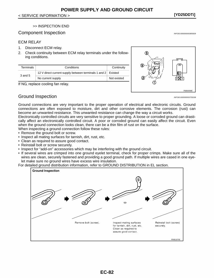
[YD25DDTi]POWER SUPPLY AND GROUND CIRCUIT
< SERVICE INFORMATION >
>> INSPECTION END
Component Inspection INFOID:0000000003855839
ECM RELAY1. Disconnect ECM relay.2. Check continuity between ECM relay terminals under the follow-
ing conditions.
If NG, replace cooling fan relay.
Ground Inspection INFOID:0000000003759338
Ground connections are very important to the proper operation of electrical and electronic circuits. Groundconnections are often exposed to moisture, dirt and other corrosive elements. The corrosion (rust) canbecome an unwanted resistance. This unwanted resistance can change the way a circuit works.Electronically controlled circuits are very sensitive to proper grounding. A loose or corroded ground can drasti-cally affect an electronically controlled circuit. A poor or corroded ground can easily affect the circuit. Evenwhen the ground connection looks clean, there can be a thin film of rust on the surface.When inspecting a ground connection follow these rules:• Remove the ground bolt or screw.• Inspect all mating surfaces for tarnish, dirt, rust, etc.• Clean as required to assure good contact.• Reinstall bolt or screw securely.• Inspect for “add-on” accessories which may be interfering with the ground circuit.• If several wires are crimped into one ground eyelet terminal, check for proper crimps. Make sure all of the
wires are clean, securely fastened and providing a good ground path. If multiple wires are cased in one eye-let make sure no ground wires have excess wire insulation.
For detailed ground distribution information, refer to GROUND DISTRIBUTION in EL section.
Terminals Conditions Continuity
3 and 512 V direct current supply between terminals 1 and 2 Existed
No current supply Not existed
PBIB0098E
PBIB1870E
EC-82

DTC U1000 CAN COMMUNICATION LINE[YD25DDTi]
C
D
E
F
G
H
I
J
K
L
M
A
C
N
P
O
< SERVICE INFORMATION >
E
DTC U1000 CAN COMMUNICATION LINE
Description INFOID:0000000003759339
CAN (Controller Area Network) is a serial communication line for real time application. It is an on-vehicle mul-tiplex communication line with high data communication speed and excellent error detection ability. Many elec-tronic control units are equipped onto a vehicle, and each control unit shares information and links with othercontrol units during operation (not independent). In CAN communication, control units are connected with 2communication lines (CAN H line, CAN L line) allowing a high rate of information transmission with less wiring.Each control unit transmits/receives data but selectively reads required data only.
On Board Diagnosis Logic INFOID:0000000003759340
This self-diagnosis has the one trip detection logic.The MI will not light up for this self-diagnosis.
DTC Confirmation Procedure INFOID:0000000003759341
1. Turn ignition switch ON and wait at least 3 seconds.2. Check DTC.3. If DTC is detected, go to EC-84, "Diagnosis Procedure".
DTC No.Trouble diagnosis
nameDTC detecting condition Possible cause
U10001000
CAN communication line
When ECM is not transmitting or receiving CAN communication signal of OBD (emission-related diagnosis) for 2 seconds or more.
• Harness or connectors(CAN communication line is open or shorted)
EC-83

[YD25DDTi]DTC U1000 CAN COMMUNICATION LINE
< SERVICE INFORMATION >
Wiring Diagram INFOID:0000000003759342
Diagnosis Procedure INFOID:0000000003759343
Go to EL-110, "CAN System Specification Chart".
GEC601A
EC-84
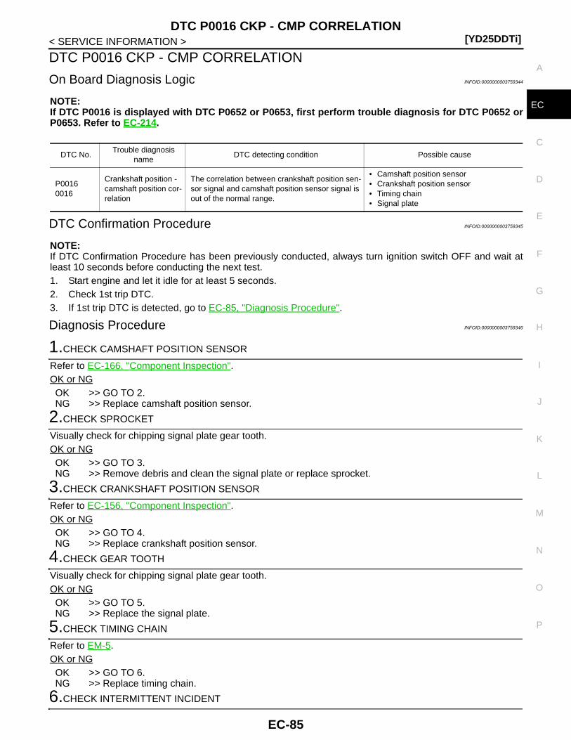
DTC P0016 CKP - CMP CORRELATION[YD25DDTi]
C
D
E
F
G
H
I
J
K
L
M
A
C
N
P
O
< SERVICE INFORMATION >
E
DTC P0016 CKP - CMP CORRELATION
On Board Diagnosis Logic INFOID:0000000003759344
NOTE:If DTC P0016 is displayed with DTC P0652 or P0653, first perform trouble diagnosis for DTC P0652 orP0653. Refer to EC-214.
DTC Confirmation Procedure INFOID:0000000003759345
NOTE:If DTC Confirmation Procedure has been previously conducted, always turn ignition switch OFF and wait atleast 10 seconds before conducting the next test.1. Start engine and let it idle for at least 5 seconds.2. Check 1st trip DTC.3. If 1st trip DTC is detected, go to EC-85, "Diagnosis Procedure".
Diagnosis Procedure INFOID:0000000003759346
1.CHECK CAMSHAFT POSITION SENSOR
Refer to EC-166, "Component Inspection".OK or NGOK >> GO TO 2.NG >> Replace camshaft position sensor.
2.CHECK SPROCKET
Visually check for chipping signal plate gear tooth.OK or NGOK >> GO TO 3.NG >> Remove debris and clean the signal plate or replace sprocket.
3.CHECK CRANKSHAFT POSITION SENSOR
Refer to EC-156, "Component Inspection".OK or NGOK >> GO TO 4.NG >> Replace crankshaft position sensor.
4.CHECK GEAR TOOTH
Visually check for chipping signal plate gear tooth.OK or NGOK >> GO TO 5.NG >> Replace the signal plate.
5.CHECK TIMING CHAIN
Refer to EM-5.OK or NGOK >> GO TO 6.NG >> Replace timing chain.
6.CHECK INTERMITTENT INCIDENT
DTC No.Trouble diagnosis
nameDTC detecting condition Possible cause
P00160016
Crankshaft position - camshaft position cor-relation
The correlation between crankshaft position sen-sor signal and camshaft position sensor signal is out of the normal range.
• Camshaft position sensor• Crankshaft position sensor• Timing chain• Signal plate
EC-85

[YD25DDTi]DTC P0016 CKP - CMP CORRELATION
< SERVICE INFORMATION >Refer to EC-70.
>> INSPECTION END
EC-86

DTC P0088 FUEL SYSTEM[YD25DDTi]
C
D
E
F
G
H
I
J
K
L
M
A
C
N
P
O
< SERVICE INFORMATION >
E
DTC P0088 FUEL SYSTEM
On Board Diagnosis Logic INFOID:0000000003759355
NOTE:If DTC P0088 is displayed with DTC P0652 or P0653, first perform trouble diagnosis for DTC P0652 orP0653. Refer to EC-214.
DTC Confirmation Procedure INFOID:0000000003759356
NOTE:If DTC Confirmation Procedure has been previously conducted, always turn ignition switch OFF and wait atleast 10 seconds before conducting the next test.1. Start engine and warm it up to normal operating temperature.2. Keep engine speed more than 2,000 rpm for at least 20 seconds.3. Check 1st trip DTC.4. If 1st trip DTC is detected, go to EC-87, "Diagnosis Procedure".
Diagnosis Procedure INFOID:0000000003759357
1.CHECK FUEL RAIL PRESSURE SENSOR
Refer to EC-131, "Component Inspection".OK or NGOK >> GO TO 2.NG >> Replace fuel rail.
2.CHECK FUEL INJECTOR
Refer to EC-137, "Component Inspection".OK or NGOK >> GO TO 4.NG >> GO TO 3.
3.REPLACE FUEL INJECOR
1. Replace fuel injector of malfunctioning cylinder.2. Perform Injector Adjustment Value Registration. Refer to EC-22, "Injector Adjustment Value Registration".
>> INSPECTION END
4.CHECK FUEL PUMP
Refer to EC-208, "Component Inspection".OK or NGOK >> GO TO 6.NG >> GO TO 5.
5.REPLACE FUEL PUMP
1. Replace fuel pump.2. Perform Fuel Pump Learning Value Clearing. Refer to EC-23, "Fuel Pump Learning Value Clearing".
>> INSPECTION END
6.CHECK INTERMITTENT INCIDENT
DTC No. Trouble diagnosis name DTC detecting condition Possible cause
P00880088
Fuel rail pressure too highFuel pressure is too much higher than the speci-fied value.
• Fuel pump• Fuel injector• Fuel rail pressure sensor
EC-87

[YD25DDTi]DTC P0088 FUEL SYSTEM
< SERVICE INFORMATION >Refer to EC-70.
>> INSPECTION END
Removal and Installation INFOID:0000000003759358
FUEL INJECTORRefer to EM-8.
FUEL PUMPRefer to EC-24.
EC-88
DTC P0089 FUEL PUMP[YD25DDTi]
C
D
E
F
G
H
I
J
K
L
M
A
C
N
P
O
< SERVICE INFORMATION >
E
DTC P0089 FUEL PUMP
On Board Diagnosis Logic INFOID:0000000003759359
NOTE:If DTC P0089 is displayed with DTC P0652 or P0653, first perform trouble diagnosis for DTC P0652 orP0653. Refer to EC-214.
DTC Confirmation Procedure INFOID:0000000003759360
NOTE:If DTC Confirmation Procedure has been previously conducted, always turn ignition switch OFF and wait atleast 10 seconds before conducting the next test.1. Start engine and warm it up to normal operating temperature.2. Let engine idle for at least 30 seconds.3. Check 1st trip DTC.4. If 1st trip DTC is detected, go to EC-89, "Diagnosis Procedure".
Diagnosis Procedure INFOID:0000000003759361
1.PERFORM FUEL PUMP LEARNING VALUE CLEARING
NOTE:If the DTC is detected because of air mixed with fuel (i.e.: caused by lack of fuel), it may become normal byperforming following procedure.
With CONSULT-III1. Turn ignition switch ON.2. Perform Fuel Pump Learning Value Clearing. Refer to EC-23, "Fuel Pump Learning Value Clearing".3. Start engine and let it idle for at least 60 seconds.4. Select “SELF-DIAG RESULT” mode with CONSULT-III.5. Touch “ERASE”.6. Perform EC-89, "DTC Confirmation Procedure", again.7. Is 1st trip DTC detected again?
With GST1. Turn ignition switch ON.2. Perform Fuel Pump Learning Value Clearing. Refer to EC-23, "Fuel Pump Learning Value Clearing".3. Start engine and let it idle for at least 60 seconds.4. Select Service $04 with GST.5. Perform EC-89, "DTC Confirmation Procedure", again.6. Is 1st trip DTC detected again?Yes or NoYes >> GO TO 2.No >> INSPECTION END
2.CHECK FUEL RAIL PRESSURE SENSOR
Refer to EC-131, "Component Inspection".OK or NGOK >> GO TO 3.NG >> Replace fuel rail.
3.CHECK FUEL PUMP
Perform EC-205, "DTC Confirmation Procedure".
DTC No. Trouble diagnosis name DTC detecting condition Possible cause
P00890089
Fuel pump performance Fuel pressure is too much higher than the target value.
• Fuel pump• Air mixed with fuel• Lack of fuel• Fuel rail pressure sensor
EC-89

[YD25DDTi]DTC P0089 FUEL PUMP
< SERVICE INFORMATION >OK or NGOK >> GO TO 5.NG >> GO TO 4.
4.REPLACE FUEL PUMP
1. Replace Fuel pump.2. Perform Fuel Pump Learning Value Clearing. Refer to EC-23, "Fuel Pump Learning Value Clearing".
>> INSPECTION END
5.CHECK INTERMITTENT INCIDENT
Refer to EC-70.
>> INSPECTION END
Removal and Installation INFOID:0000000003759362
FUEL PUMPRefer to EC-24.
EC-90

DTC P0093 FUEL SYSTEM[YD25DDTi]
C
D
E
F
G
H
I
J
K
L
M
A
C
N
P
O
< SERVICE INFORMATION >
E
DTC P0093 FUEL SYSTEM
On Board Diagnosis Logic INFOID:0000000003759363
NOTE:If DTC P0093 is displayed with DTC P0652 or P0653, first perform trouble diagnosis for DTC P0652 orP0653. Refer to EC-214.
Overall Function Check INFOID:0000000003759364
Use this procedure to check the overall function of the fuel system. During this check, a 1st trip DTC might notbe confirmed.NOTE:• Make sure that there is no fire hazard near the vehicle.• Before performing the following procedure, cool down engine.
WITH CONSULT-III1. Open engine hood and check if there are any signs of fuel leakage or not.
If there are any signs, go to EC-92, "Diagnosis Procedure".If there is no signs, go to next step.
2. Check oil level.If oil level is above the proper range, go to EC-92, "Diagnosis Procedure".If oil level is within the proper range, go to next step.
3. Start engine and check fuel leakage in the engine room.If fuel leakage is found, go to EC-92, "Diagnosis Procedure".If fuel leakage is not found, go to next step.
4. Select “DATA MONITOR” mode with CONSULT-III.5. Check the fuel rail pressure at the idle speed.
6. If NG, go to EC-92, "Diagnosis Procedure".
WITH GST1. Open engine hood and check if there are any signs of fuel leakage or not.
If there are any signs, go to EC-92, "Diagnosis Procedure".If there is no signs, go to next step.
2. Check oil level.If oil level is above the proper range, go to EC-92, "Diagnosis Procedure".If oil level is within the proper range, go to next step.
3. Start engine and check fuel leakage in the engine room.If fuel leakage is found, go to EC-92, "Diagnosis Procedure".If fuel leakage is not found, go to next step.
4. Select Service $1 mode with GST.5. Check the fuel rail pressure at the idle speed.
6. If NG, go to EC-92, "Diagnosis Procedure".
DTC No. Trouble diagnosis name DTC detecting condition Possible cause
P00930093
Fuel system leak
ECM detects a fuel system leak.(The relation between the output voltage to the fuel pump and input voltage from the fuel rail pressure sensor is out of the normal range.)
• Fuel pump• Fuel rail• Fuel pipe• Fuel rail pressure relief valve• Air mixed with fuel• Lack of fuel
Fuel rail pressure: 25 - 35 MPa
Fuel rail pressure: 25 - 35 MPa
EC-91
[YD25DDTi]DTC P0093 FUEL SYSTEM
< SERVICE INFORMATION >
Diagnosis Procedure INFOID:0000000003759365
1.PERFORM FUEL PUMP LEARNING VALUE CLEARING
NOTE:If the DTC is detected because of air mixed with fuel (i.e.: caused by lack of fuel), it may become normal byperforming following procedure.
With CONSULT-III1. Turn ignition switch ON.2. Perform Fuel Pump Learning Value Clearing. Refer to EC-23, "Fuel Pump Learning Value Clearing".3. Start engine and let it idle for at least 60 seconds.4. Select “SELF-DIAG RESULT” mode with CONSULT-III.5. Touch “ERASE”.6. Perform EC-91, "Overall Function Check", again.7. Is the result NG again?
With GST1. Turn ignition switch ON.2. Perform Fuel Pump Learning Value Clearing. Refer to EC-23, "Fuel Pump Learning Value Clearing".3. Start engine and let it idle for at least 60 seconds.4. Select Service $04 with GST.5. Perform EC-91, "Overall Function Check", again.6. Is the result NG again?Yes or NoYes >> GO TO 2.No >> INSPECTION END
2.CHECK FUEL LINE FOR LEAK
1. Start engine.2. Visually check the following for fuel leak.- Fuel tube from fuel pump to fuel rail- Fuel rail- Fuel tube from fuel rail to fuel injector3. Also check for improper connection or pinches.OK or NGOK >> GO TO 3.NG >> Repair malfunctioning part.
3.CHECK FUEL RAIL PRESSURE RELIEF VALVE
Refer to EC-92, "Component Inspection".OK or NGOK >> GO TO 4.NG >> Replace fuel rail.
4.CHECK INTERMITTENT INCIDENT
Refer to EC-70.OK or NGOK >> GO TO 5.NG >> Repair or replace.
5.REPLACE FUEL PUMP
1. Replace fuel pump.2. Perform Fuel Pump Learning Value Clearing. Refer to EC-23, "Fuel Pump Learning Value Clearing".
>> INSPECTION END
Component Inspection INFOID:0000000003759366
FUEL RAIL PRESSURE RELIEF VALVE
EC-92
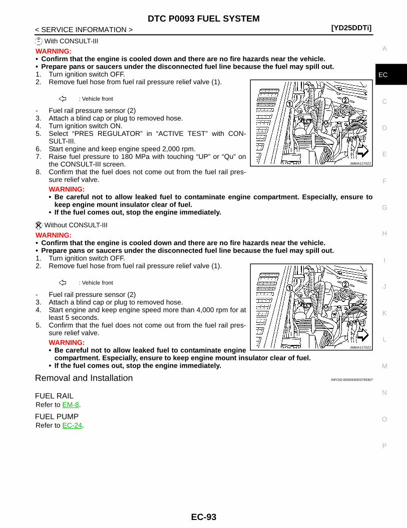
DTC P0093 FUEL SYSTEM[YD25DDTi]
C
D
E
F
G
H
I
J
K
L
M
A
C
N
P
O
< SERVICE INFORMATION >
E
With CONSULT-III
WARNING:• Confirm that the engine is cooled down and there are no fire hazards near the vehicle.• Prepare pans or saucers under the disconnected fuel line because the fuel may spill out.1. Turn ignition switch OFF.2. Remove fuel hose from fuel rail pressure relief valve (1).
- Fuel rail pressure sensor (2)3. Attach a blind cap or plug to removed hose.4. Turn ignition switch ON.5. Select “PRES REGULATOR” in “ACTIVE TEST” with CON-
SULT-III.6. Start engine and keep engine speed 2,000 rpm.7. Raise fuel pressure to 180 MPa with touching “UP” or “Qu” on
the CONSULT-III screen.8. Confirm that the fuel does not come out from the fuel rail pres-
sure relief valve.WARNING:• Be careful not to allow leaked fuel to contaminate engine compartment. Especially, ensure to
keep engine mount insulator clear of fuel.• If the fuel comes out, stop the engine immediately.
Without CONSULT-III
WARNING:• Confirm that the engine is cooled down and there are no fire hazards near the vehicle.• Prepare pans or saucers under the disconnected fuel line because the fuel may spill out.1. Turn ignition switch OFF.2. Remove fuel hose from fuel rail pressure relief valve (1).
- Fuel rail pressure sensor (2)3. Attach a blind cap or plug to removed hose.4. Start engine and keep engine speed more than 4,000 rpm for at
least 5 seconds.5. Confirm that the fuel does not come out from the fuel rail pres-
sure relief valve.WARNING:• Be careful not to allow leaked fuel to contaminate engine
compartment. Especially, ensure to keep engine mount insulator clear of fuel.• If the fuel comes out, stop the engine immediately.
Removal and Installation INFOID:0000000003759367
FUEL RAILRefer to EM-8.
FUEL PUMPRefer to EC-24.
: Vehicle front
JMBIA1270ZZ
: Vehicle front
JMBIA1270ZZ
EC-93

[YD25DDTi]DTC P0101 MAF SENSOR
< SERVICE INFORMATION >
DTC P0101 MAF SENSOR
Component Description INFOID:0000000003759368
The mass air flow sensor (1) is placed in the stream of intake air. Itmeasures the intake flow rate by measuring a part of the entireintake flow. The mass air flow sensor controls the temperature of thehot wire to a certain amount. The heat generated by the hot wire isreduced as the intake air flows around it. The more air, the greaterthe heat loss.Therefore, the electric current supplied to hot wire is changed tomaintain the temperature of the hot wire as air flow increases. TheECM detects the air flow by means of this current change.
CONSULT-III Reference Value in Data Monitor Mode INFOID:0000000003759369
Specification data are reference values.
*: This signal is converted by ECM internally. Thus this differs from ECM terminal voltage.
On Board Diagnosis Logic INFOID:0000000003759370
If DTC P0101 is displayed with DTC P0403, first perform trouble diagnosis for DTC P0403. Refer to EC-177.If DTC P0101 is displayed with DTC P0409, first perform trouble diagnosis for DTC P0409. Refer to EC-190.If DTC P0101 is displayed with DTC P0488, first perform trouble diagnosis for DTC P0488. Refer to EC-196.
DTC Confirmation Procedure INFOID:0000000003759371
CAUTION:Always drive vehicle at a safe speed.NOTE:If DTC Confirmation Procedure has been previously conducted, always turn ignition switch OFF and wait atleast 10 seconds before conducting the next test.
WITH CONSULT-III1. Turn ignition switch ON.2. Select “DATA MONITOR” mode with CONSULT-III.
PBIA9559J
MONITOR ITEM CONDITION SPECIFICATION
MAS AIR/FL SE*
• Engine: After warming up • Air conditioner switch: OFF• Shift lever: Neutral position• No load
Ignition switch: ON (Engine stopped)
Approximately 0.4 V
Idle 1.3 - 1.8 V
Engine is revving from idle to about 4,000 rpm.
1.3 - 1.8 V to Approximately 4.0 V(Check for liner voltage rise in re-sponse to engine being increased to about 4,000 rpm)
DTC No. Trouble diagnosis name DTC detecting condition Possible cause
P01010101
Mass air flow sensor cir-cuit range/performance
Improper voltage from the sensor is sent to ECM compared with the driving condition.
• Harness or connectors(The sensor circuit is open or shorted.)
• Mass air flow sensor• Intake air leaks• Air cleaner• Intake air temperature sensor• EGR volume control valve
EC-94
DTC P0101 MAF SENSOR[YD25DDTi]
C
D
E
F
G
H
I
J
K
L
M
A
C
N
P
O
< SERVICE INFORMATION >
E
3. Start engine and let it idle for at least 40 seconds.4. Drive vehicle under the following condition.
5. Release accelerator pedal for at least 10 seconds.Do not depress brake pedal during this procedure.
6. Check 1st trip DTC.7. If 1st trip DTC is detected, go to EC-99, "Diagnosis Procedure".
WITH GSTFollow the procedure “WITH CONSULT-III” above.
CKPS·RPM Approx. 2800 rpm
VHCL SPEED SE 70 - 100 km/h (43 - 62 MPH)
Shift lever 4th position
EC-95
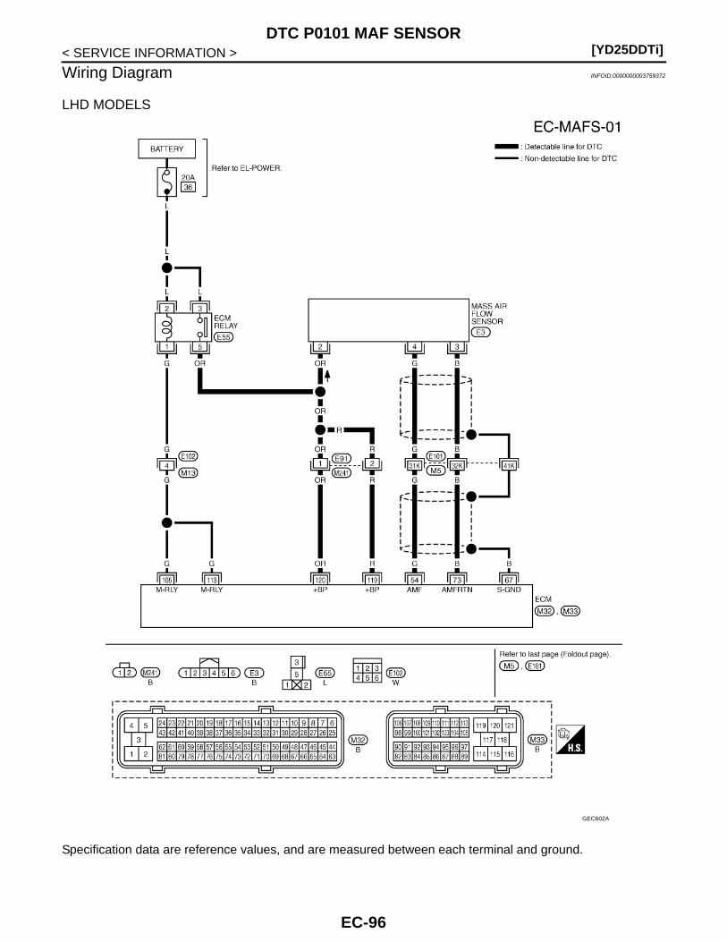
[YD25DDTi]DTC P0101 MAF SENSOR
< SERVICE INFORMATION >
Wiring Diagram INFOID:0000000003759372
LHD MODELS
Specification data are reference values, and are measured between each terminal and ground.
GEC602A
EC-96

DTC P0101 MAF SENSOR[YD25DDTi]
C
D
E
F
G
H
I
J
K
L
M
A
C
N
P
O
< SERVICE INFORMATION >
E
: Average voltage for pulse signal (Actual pulse signal can be confirmed by oscilloscope.)
TERMINAL NO.(Wire color)
DescriptionCondition
Value (Approx.)
+ − Signal name
54(G)
73(B)
Mass air flow sensor
[Ignition switch ON] Approximately 0.4 V
[Engine is running]• Warm-up condition• Idle speed
1.3 - 1.8 V
[Engine is running]• Warm-up condition• Engine is revving from idle to about
4,000 rpm.
1.3 - 1.8 V to Approximately 4.0 V(Check for liner voltage rise in re-sponse to engine being increased to about 4,000 rpm)
67(B)
—Sensor ground(Sensor shield circuit)
— —
73(B)
— Mass air flow sensor ground — —
105(G)113(G)
114(B)
ECM relay (self shut-off)
[Ignition switch ON][Ignition switch OFF]• For a few seconds after turning ignition
switch OFF
0 - 1.0 V
[Ignition switch OFF]• More than a few seconds after turning
ignition switch OFF
BATTERY VOLTAGE(11 - 14 V)
119(R)120(OR)
114(B)
Power supply for ECM [Ignition switch ON]BATTERY VOLTAGE(11 - 14 V)
EC-97
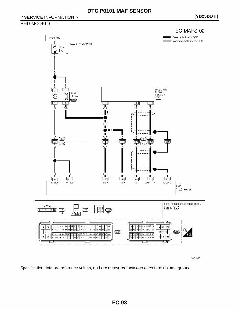
[YD25DDTi]DTC P0101 MAF SENSOR
< SERVICE INFORMATION >
RHD MODELS
Specification data are reference values, and are measured between each terminal and ground.
GEC603A
EC-98
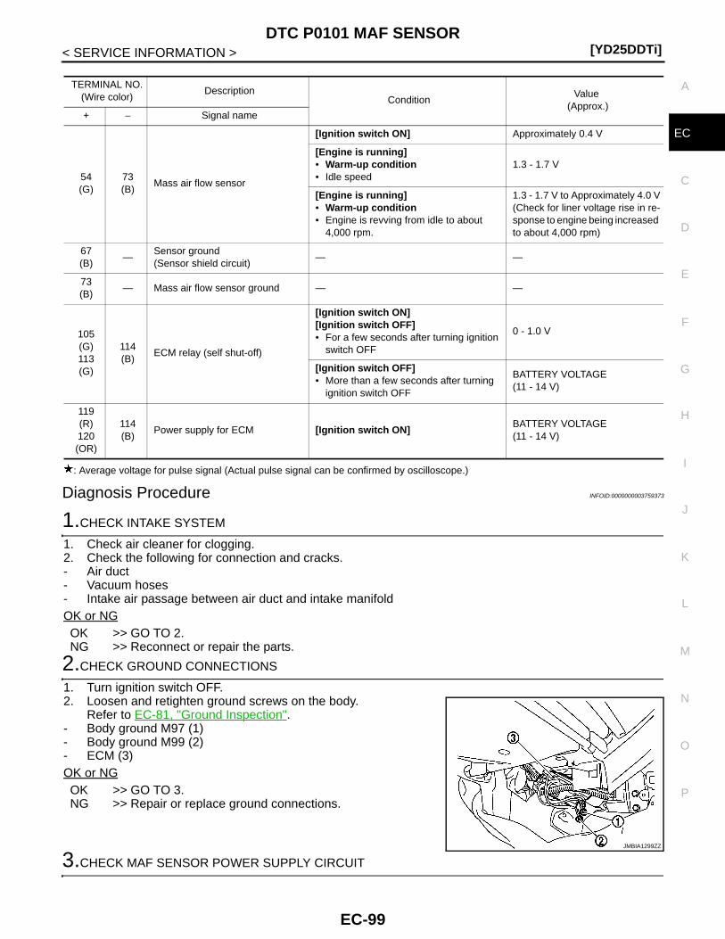
DTC P0101 MAF SENSOR[YD25DDTi]
C
D
E
F
G
H
I
J
K
L
M
A
C
N
P
O
< SERVICE INFORMATION >
E
: Average voltage for pulse signal (Actual pulse signal can be confirmed by oscilloscope.)
Diagnosis Procedure INFOID:0000000003759373
1.CHECK INTAKE SYSTEM
1. Check air cleaner for clogging.2. Check the following for connection and cracks.- Air duct- Vacuum hoses- Intake air passage between air duct and intake manifoldOK or NGOK >> GO TO 2.NG >> Reconnect or repair the parts.
2.CHECK GROUND CONNECTIONS
1. Turn ignition switch OFF.2. Loosen and retighten ground screws on the body.
Refer to EC-81, "Ground Inspection".- Body ground M97 (1)- Body ground M99 (2)- ECM (3)OK or NGOK >> GO TO 3.NG >> Repair or replace ground connections.
3.CHECK MAF SENSOR POWER SUPPLY CIRCUIT
TERMINAL NO.(Wire color)
DescriptionCondition
Value (Approx.)
+ − Signal name
54(G)
73(B)
Mass air flow sensor
[Ignition switch ON] Approximately 0.4 V
[Engine is running]• Warm-up condition• Idle speed
1.3 - 1.7 V
[Engine is running]• Warm-up condition• Engine is revving from idle to about
4,000 rpm.
1.3 - 1.7 V to Approximately 4.0 V(Check for liner voltage rise in re-sponse to engine being increased to about 4,000 rpm)
67(B)
—Sensor ground(Sensor shield circuit)
— —
73(B)
— Mass air flow sensor ground — —
105(G)113(G)
114(B)
ECM relay (self shut-off)
[Ignition switch ON][Ignition switch OFF]• For a few seconds after turning ignition
switch OFF
0 - 1.0 V
[Ignition switch OFF]• More than a few seconds after turning
ignition switch OFF
BATTERY VOLTAGE(11 - 14 V)
119(R)120(OR)
114(B)
Power supply for ECM [Ignition switch ON]BATTERY VOLTAGE(11 - 14 V)
JMBIA1299ZZ
EC-99
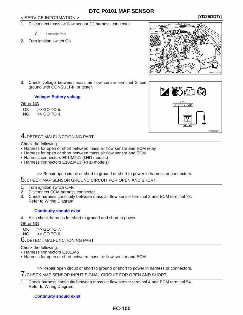
[YD25DDTi]DTC P0101 MAF SENSOR
< SERVICE INFORMATION >1. Disconnect mass air flow sensor (1) harness connector.
2. Turn ignition switch ON.
3. Check voltage between mass air flow sensor terminal 2 andground with CONSULT-III or tester.
OK or NGOK >> GO TO 5.NG >> GO TO 4.
4.DETECT MALFUNCTIONING PART
Check the following.• Harness for open or short between mass air flow sensor and ECM relay• Harness for open or short between mass air flow sensor and ECM• Harness connectors E91,M241 (LHD models)• Harness connectors E102,M13 (RHD models)
>> Repair open circuit or short to ground or short to power in harness or connectors.
5.CHECK MAF SENSOR GROUND CIRCUIT FOR OPEN AND SHORT
1. Turn ignition switch OFF.2. Disconnect ECM harness connector.3. Check harness continuity between mass air flow sensor terminal 3 and ECM terminal 73.
Refer to Wiring Diagram.
4. Also check harness for short to ground and short to power.OK or NGOK >> GO TO 7.NG >> GO TO 6.
6.DETECT MALFUNCTIONING PART
Check the following.• Harness connectors E101,M5• Harness for open or short between mass air flow sensor and ECM
>> Repair open circuit or short to ground or short to power in harness or connectors.
7.CHECK MAF SENSOR INPUT SIGNAL CIRCUIT FOR OPEN AND SHORT
1. Check harness continuity between mass air flow sensor terminal 4 and ECM terminal 54.Refer to Wiring Diagram.
: Vehicle front
JMBIA1281ZZ
Voltage: Battery voltage
PBIB1168E
Continuity should exist.
Continuity should exist.
EC-100
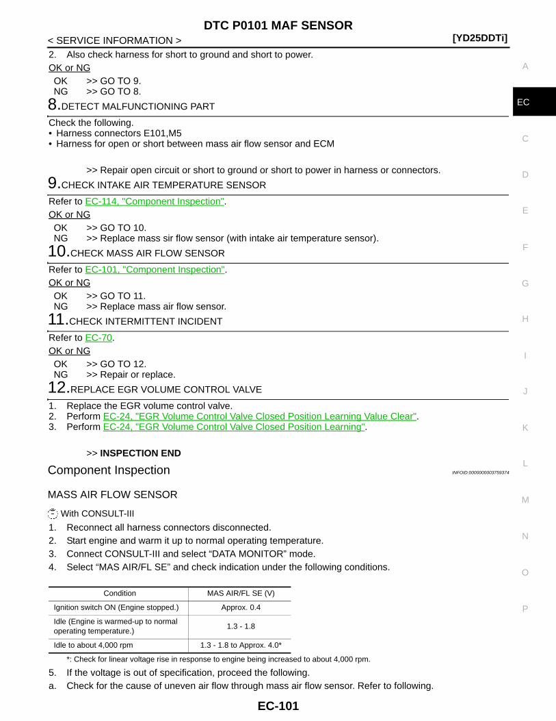
DTC P0101 MAF SENSOR[YD25DDTi]
C
D
E
F
G
H
I
J
K
L
M
A
C
N
P
O
< SERVICE INFORMATION >
E
2. Also check harness for short to ground and short to power.OK or NGOK >> GO TO 9.NG >> GO TO 8.
8.DETECT MALFUNCTIONING PART
Check the following.• Harness connectors E101,M5• Harness for open or short between mass air flow sensor and ECM
>> Repair open circuit or short to ground or short to power in harness or connectors.
9.CHECK INTAKE AIR TEMPERATURE SENSOR
Refer to EC-114, "Component Inspection".OK or NGOK >> GO TO 10.NG >> Replace mass sir flow sensor (with intake air temperature sensor).
10.CHECK MASS AIR FLOW SENSOR
Refer to EC-101, "Component Inspection".OK or NGOK >> GO TO 11.NG >> Replace mass air flow sensor.
11.CHECK INTERMITTENT INCIDENT
Refer to EC-70.OK or NGOK >> GO TO 12.NG >> Repair or replace.
12.REPLACE EGR VOLUME CONTROL VALVE
1. Replace the EGR volume control valve.2. Perform EC-24, "EGR Volume Control Valve Closed Position Learning Value Clear".3. Perform EC-24, "EGR Volume Control Valve Closed Position Learning".
>> INSPECTION END
Component Inspection INFOID:0000000003759374
MASS AIR FLOW SENSOR
With CONSULT-III
1. Reconnect all harness connectors disconnected.2. Start engine and warm it up to normal operating temperature.3. Connect CONSULT-III and select “DATA MONITOR” mode.4. Select “MAS AIR/FL SE” and check indication under the following conditions.
*: Check for linear voltage rise in response to engine being increased to about 4,000 rpm.
5. If the voltage is out of specification, proceed the following.a. Check for the cause of uneven air flow through mass air flow sensor. Refer to following.
Condition MAS AIR/FL SE (V)
Ignition switch ON (Engine stopped.) Approx. 0.4
Idle (Engine is warmed-up to normal operating temperature.)
1.3 - 1.8
Idle to about 4,000 rpm 1.3 - 1.8 to Approx. 4.0*
EC-101

[YD25DDTi]DTC P0101 MAF SENSOR
< SERVICE INFORMATION >• Crushed air ducts• Malfunctioning seal of air cleaner element• Uneven dirt of air cleaner element• Improper specification of intake air system parts
b. If NG, repair or replace malfunctioning part and perform step 2 to 4 again.If OK, go to next step.
6. Turn ignition switch OFF.7. Disconnect mass air flow sensor harness connector and reconnect it again.8. Perform step 2 to 4 again.9. If NG, clean or replace mass air flow sensor.
Without CONSULT-III
1. Reconnect all harness connectors disconnected.2. Start engine and warm it up to normal operating temperature.3. Check voltage between ECM harness connectors as follows.
*: Check for linear voltage rise in response to engine being increased to about 4,000 rpm.
4. If the voltage is out of specification, proceed the following.a. Check for the cause of uneven air flow through mass air flow sensor. Refer to following.
• Crushed air ducts• Malfunctioning seal of air cleaner element• Uneven dirt of air cleaner element• Improper specification of intake air system parts
b. If NG, repair or replace malfunctioning part and perform step 2 and 3 again.If OK, go to next step.
5. Turn ignition switch OFF.6. Disconnect mass air flow sensor harness connector and reconnect it again.7. Perform step 2 and 3 again.8. If NG, clean or replace mass air flow sensor.
Removal and Installation INFOID:0000000003759375
MASS AIR FLOW SENSORRefer to EM-6.
ECM
Condition VoltageConnector
+ –
Terminal Terminal
M3254
(MAF sensor signal)73
(Sensor ground)
Ignition switch ON (Engine stopped.) Approx. 0.4 V
Idle (Engine is warmed-up to normal operating temperature.)
1.3 - 1.8 V
Idle to about 4,000 rpm1.3 - 1.8 V to Ap-
prox. 4.0 V*
EC-102
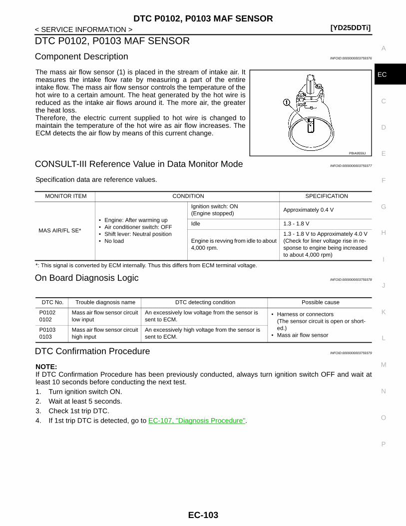
DTC P0102, P0103 MAF SENSOR[YD25DDTi]
C
D
E
F
G
H
I
J
K
L
M
A
C
N
P
O
< SERVICE INFORMATION >
E
DTC P0102, P0103 MAF SENSOR
Component Description INFOID:0000000003759376
The mass air flow sensor (1) is placed in the stream of intake air. Itmeasures the intake flow rate by measuring a part of the entireintake flow. The mass air flow sensor controls the temperature of thehot wire to a certain amount. The heat generated by the hot wire isreduced as the intake air flows around it. The more air, the greaterthe heat loss.Therefore, the electric current supplied to hot wire is changed tomaintain the temperature of the hot wire as air flow increases. TheECM detects the air flow by means of this current change.
CONSULT-III Reference Value in Data Monitor Mode INFOID:0000000003759377
Specification data are reference values.
*: This signal is converted by ECM internally. Thus this differs from ECM terminal voltage.
On Board Diagnosis Logic INFOID:0000000003759378
DTC Confirmation Procedure INFOID:0000000003759379
NOTE:If DTC Confirmation Procedure has been previously conducted, always turn ignition switch OFF and wait atleast 10 seconds before conducting the next test. 1. Turn ignition switch ON.2. Wait at least 5 seconds.3. Check 1st trip DTC.4. If 1st trip DTC is detected, go to EC-107, "Diagnosis Procedure".
PBIA9559J
MONITOR ITEM CONDITION SPECIFICATION
MAS AIR/FL SE*
• Engine: After warming up • Air conditioner switch: OFF• Shift lever: Neutral position• No load
Ignition switch: ON (Engine stopped)
Approximately 0.4 V
Idle 1.3 - 1.8 V
Engine is revving from idle to about 4,000 rpm.
1.3 - 1.8 V to Approximately 4.0 V(Check for liner voltage rise in re-sponse to engine being increased to about 4,000 rpm)
DTC No. Trouble diagnosis name DTC detecting condition Possible cause
P01020102
Mass air flow sensor circuit low input
An excessively low voltage from the sensor is sent to ECM.
• Harness or connectors(The sensor circuit is open or short-ed.)
• Mass air flow sensorP01030103
Mass air flow sensor circuit high input
An excessively high voltage from the sensor is sent to ECM.
EC-103

[YD25DDTi]DTC P0102, P0103 MAF SENSOR
< SERVICE INFORMATION >
Wiring Diagram INFOID:0000000003759380
LHD MODELS
Specification data are reference values, and are measured between each terminal and ground.
GEC602A
EC-104

DTC P0102, P0103 MAF SENSOR[YD25DDTi]
C
D
E
F
G
H
I
J
K
L
M
A
C
N
P
O
< SERVICE INFORMATION >
E
TERMINAL NO.(Wire color)
DescriptionCondition
Value (Approx.)
+ − Signal name
54(G)
73(B)
Mass air flow sensor
[Ignition switch ON] Approximately 0.4 V
[Engine is running]• Warm-up condition• Idle speed
1.3 - 1.8 V
[Engine is running]• Warm-up condition• Engine is revving from idle to about
4,000 rpm.
1.3 - 1.8 V to Approximately 4.0 V(Check for liner voltage rise in re-sponse to engine being increased to about 4,000 rpm)
67(B)
—Sensor ground(Sensor shield circuit)
— —
73(B)
— Mass air flow sensor ground — —
105(G)
114(B)
ECM relay (self shut-off)
[Ignition switch ON][Ignition switch OFF]• For a few seconds after turning ignition
switch OFF
0 - 1.0 V
113(G)
[Ignition switch OFF]• More than a few seconds after turning
ignition switch OFF
BATTERY VOLTAGE(11 - 14 V)
119(R)120(OR)
114(B)
Power supply for ECM [Ignition switch ON]BATTERY VOLTAGE(11 - 14 V)
EC-105

[YD25DDTi]DTC P0102, P0103 MAF SENSOR
< SERVICE INFORMATION >
RHD MODELS
Specification data are reference values, and are measured between each terminal and ground.
GEC603A
EC-106

DTC P0102, P0103 MAF SENSOR[YD25DDTi]
C
D
E
F
G
H
I
J
K
L
M
A
C
N
P
O
< SERVICE INFORMATION >
E
Diagnosis Procedure INFOID:0000000003759381
1.CHECK GROUND CONNECTIONS
1. Turn ignition switch OFF.2. Loosen and retighten ground screws on the body.
Refer to EC-81, "Ground Inspection".- Body ground M97 (1)- Body ground M99 (2)- ECM (3)OK or NGOK >> GO TO 2.NG >> Repair or replace ground connections.
2.CHECK MAF SENSOR POWER SUPPLY CIRCUIT
1. Disconnect mass air flow sensor (1) harness connector.
2. Turn ignition switch ON.
TERMINAL NO.(Wire color)
DescriptionCondition
Value (Approx.)
+ − Signal name
54(G)
73(B)
Mass air flow sensor
[Ignition switch ON] Approximately 0.4 V
[Engine is running]• Warm-up condition• Idle speed
1.3 - 1.8 V
[Engine is running]• Warm-up condition• Engine is revving from idle to about
4,000 rpm.
1.3 - 1.8 V to Approximately 4.0 V(Check for liner voltage rise in re-sponse to engine being increased to about 4,000 rpm)
67(B)
—Sensor ground(Sensor shield circuit)
— —
73(B)
— Mass air flow sensor ground — —
105(G)
114(B)
ECM relay (self shut-off)
[Ignition switch ON][Ignition switch OFF]• For a few seconds after turning ignition
switch OFF
0 - 1.0 V
113(BR)
[Ignition switch OFF]• More than a few seconds after turning
ignition switch OFF
BATTERY VOLTAGE(11 - 14 V)
119(R)120(OR)
114(B)
Power supply for ECM [Ignition switch ON]BATTERY VOLTAGE(11 - 14 V)
JMBIA1299ZZ
: Vehicle front
JMBIA1281ZZ
EC-107

[YD25DDTi]DTC P0102, P0103 MAF SENSOR
< SERVICE INFORMATION >3. Check voltage between mass air flow sensor terminal 2 and
ground with CONSULT-III or tester.
OK or NGOK >> GO TO 4.NG >> GO TO 3.
3.DETECT MALFUNCTIONING PART
Check the following.• Harness for open or short between mass air flow sensor and ECM relay• Harness for open or short between mass air flow sensor and ECM• Harness connectors E91,M241 (LHD models)• Harness connectors E102,M13 (RHD models)
>> Repair open circuit or short to ground or short to power in harness or connectors.
4.CHECK MAF SENSOR GROUND CIRCUIT FOR OPEN AND SHORT
1. Turn ignition switch OFF.2. Disconnect ECM harness connector.3. Check harness continuity between mass air flow sensor terminal 3 and ECM terminal 73.
Refer to Wiring Diagram.
4. Also check harness for short to ground and short to power.OK or NGOK >> GO TO 6.NG >> GO TO 5.
5.DETECT MALFUNCTIONING PART
Check the following.• Harness connectors E101,M5• Harness for open or short between mass air flow sensor and ECM
>> Repair open circuit or short to ground or short to power in harness or connectors.
6.CHECK MAF SENSOR INPUT SIGNAL CIRCUIT FOR OPEN AND SHORT
1. Check harness continuity between mass air flow sensor terminal 4 and ECM terminal 54.Refer to Wiring Diagram.
2. Also check harness for short to ground and short to power.OK or NGOK >> GO TO 8.NG >> GO TO 7.
7.DETECT MALFUNCTIONING PART
Check the following.• Harness connectors E101,M5• Harness for open or short between mass air flow sensor and ECM
>> Repair open circuit or short to ground or short to power in harness or connectors.
Voltage: Battery voltage
PBIB1168E
Continuity should exist.
Continuity should exist.
EC-108

DTC P0102, P0103 MAF SENSOR[YD25DDTi]
C
D
E
F
G
H
I
J
K
L
M
A
C
N
P
O
< SERVICE INFORMATION >
E
8.CHECK MASS AIR FLOW SENSOR
Refer to EC-109, "Component Inspection".OK or NGOK >> GO TO 9.NG >> Replace mass air flow sensor.
9.CHECK INTERMITTENT INCIDENT
Refer to EC-70.
>> INSPECTION END
Component Inspection INFOID:0000000003759382
MASS AIR FLOW SENSOR
With CONSULT-III
1. Reconnect all harness connectors disconnected.2. Start engine and warm it up to normal operating temperature.3. Connect CONSULT-III and select “DATA MONITOR” mode.4. Select “MAS AIR/FL SE” and check indication under the following conditions.
*: Check for linear voltage rise in response to engine being increased to about 4,000 rpm.
5. If the voltage is out of specification, proceed the following.a. Check for the cause of uneven air flow through mass air flow sensor. Refer to following.
• Crushed air ducts• Malfunctioning seal of air cleaner element• Uneven dirt of air cleaner element• Improper specification of intake air system parts
b. If NG, repair or replace malfunctioning part and perform step 2 to 4 again.If OK, go to next step.
6. Turn ignition switch OFF.7. Disconnect mass air flow sensor harness connector and reconnect it again.8. Perform step 2 to 4 again.9. If NG, clean or replace mass air flow sensor.
Without CONSULT-III
1. Reconnect all harness connectors disconnected.2. Start engine and warm it up to normal operating temperature.3. Check voltage between ECM harness connectors as follows.
Condition MAS AIR/FL SE (V)
Ignition switch ON (Engine stopped.) Approx. 0.4
Idle (Engine is warmed-up to normal operating temperature.)
1.3 - 1.8
Idle to about 4,000 rpm 1.3 - 1.8 to Approx. 4.0*
EC-109

[YD25DDTi]DTC P0102, P0103 MAF SENSOR
< SERVICE INFORMATION >
*: Check for linear voltage rise in response to engine being increased to about 4,000 rpm.
4. If the voltage is out of specification, proceed the following.a. Check for the cause of uneven air flow through mass air flow sensor. Refer to following.
• Crushed air ducts• Malfunctioning seal of air cleaner element• Uneven dirt of air cleaner element• Improper specification of intake air system parts
b. If NG, repair or replace malfunctioning part and perform step 2 and 3 again.If OK, go to next step.
5. Turn ignition switch OFF.6. Disconnect mass air flow sensor harness connector and reconnect it again.7. Perform step 2 and 3 again.8. If NG, clean or replace mass air flow sensor.
Removal and Installation INFOID:0000000003759383
MASS AIR FLOW SENSORRefer to EM-6.
ECM
Condition VoltageConnector
+ –
Terminal Terminal
M3254
(MAF sensor signal)73
(Sensor ground)
Ignition switch ON (Engine stopped.) Approx. 0.4 V
Idle (Engine is warmed-up to normal operating temperature.)
1.3 - 1.8 V
Idle to about 4,000 rpm1.3 - 1.8 V to Ap-
prox. 4.0 V*
EC-110

DTC P0112, P0113 IAT SENSOR[YD25DDTi]
C
D
E
F
G
H
I
J
K
L
M
A
C
N
P
O
< SERVICE INFORMATION >
E
DTC P0112, P0113 IAT SENSOR
Component Description INFOID:0000000003759384
The intake air temperature sensor is built into mass air flow sensor(1). The sensor detects intake air temperature and transmits a signalto the ECM.The temperature sensing unit uses a thermistor which is sensitive tothe change in temperature. Electrical resistance of the thermistordecreases in response to the temperature rise.
<Reference data>
*: This data is reference values and is measured between ECM terminal 55 (Intakeair temperature sensor) and 74 (sensor ground).
On Board Diagnosis Logic INFOID:0000000003759385
DTC Confirmation Procedure INFOID:0000000003759386
NOTE:If DTC Confirmation Procedure has been previously conducted, always turn ignition switch OFF and wait atleast 10 seconds before conducting the next test. 1. Turn ignition switch ON.2. Wait at least 5 seconds.3. Check 1st trip DTC.4. If 1st trip DTC is detected, go to EC-112, "Diagnosis Procedure".
PBIA9559J
Intake air temperature [°C (°F)]
Voltage* (V) Resistance (kΩ)
25 (77) 2.4 1.800 - 2.200
80 (176) 0.8 0.283 - 0.359
SEF012P
DTC No. Trouble diagnosis name DTC detecting condition Possible cause
P01120112
Intake air temperature sen-sor circuit low input
An excessively low voltage from the sensor is sent to ECM.
• Harness or connectors(The sensor circuit is open or short-ed.)
• Intake air temperature sensorP01130113
Intake air temperature sen-sor circuit high input
An excessively high voltage from the sensor is sent to ECM.
EC-111
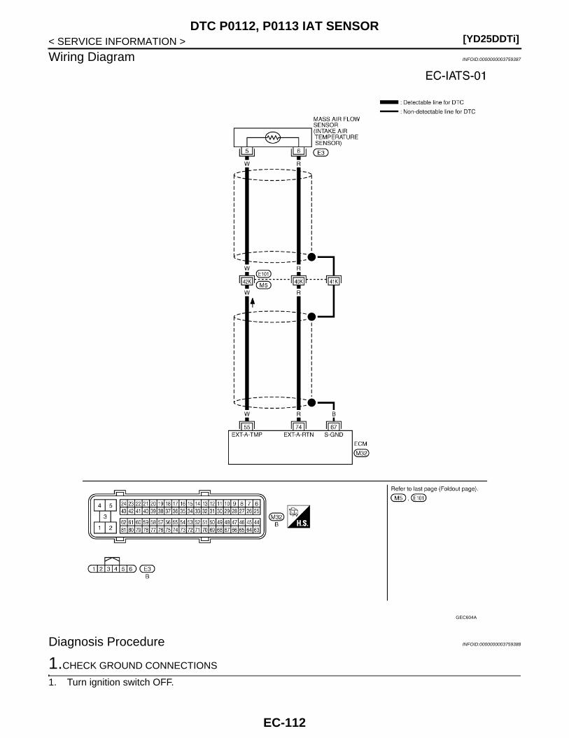
[YD25DDTi]DTC P0112, P0113 IAT SENSOR
< SERVICE INFORMATION >
Wiring Diagram INFOID:0000000003759387
Diagnosis Procedure INFOID:0000000003759388
1.CHECK GROUND CONNECTIONS
1. Turn ignition switch OFF.
GEC604A
EC-112

DTC P0112, P0113 IAT SENSOR[YD25DDTi]
C
D
E
F
G
H
I
J
K
L
M
A
C
N
P
O
< SERVICE INFORMATION >
E
2. Loosen and retighten ground screws on the body.Refer to EC-81, "Ground Inspection".
- Body ground M97 (1)- Body ground M99 (2)- ECM (3)OK or NGOK >> GO TO 2.NG >> Repair or replace ground connections.
2.CHECK INTAKE AIR TEMPERATURE SENSOR POWER SUPPLY CIRCUIT
1. Disconnect mass air flow sensor (intake air temperature sensoris built-into) (1) harness connector.
2. Turn ignition switch ON.
3. Check voltage between mass air flow sensor terminal 5 andground with CONSULT-III or tester.
OK or NGOK >> GO TO 4.NG >> GO TO 3.
3.DETECT MALFUNCTIONING PART
Check the following.• Harness connectors E101,M5• Harness for open or short between mass air flow sensor (with intake air temperature sensor) and ECM
>> Repair open circuit or short to ground or short to power in harness or connectors.
4.CHECK INTAKE AIR TEMPERATURE SENSOR GROUND CIRCUIT FOR OPEN AND SHORT
1. Turn ignition switch OFF.2. Disconnect ECM harness connector.3. Check harness continuity between mass air flow sensor terminal 6 and ECM terminal 74.
Refer to Wiring Diagram.
4. Also check harness for short to ground and short to power.OK or NGOK >> GO TO 6.NG >> GO TO 5.
5.DETECT MALFUNCTIONING PART
Check the following.
JMBIA1299ZZ
: Vehicle front
JMBIA1281ZZ
Voltage: Approximately 5 V
PBIB1169E
Continuity should exist.
EC-113

[YD25DDTi]DTC P0112, P0113 IAT SENSOR
< SERVICE INFORMATION >• Harness connectors E101,M5• Harness for open or short between mass air flow sensor (with intake air temperature sensor) and ECM
>> Repair open circuit or short to ground or short to power in harness or connectors.
6.CHECK INTAKE AIR TEMPERATURE SENSOR
Refer to EC-114, "Component Inspection".OK or NGOK >> GO TO 7.NG >> Replace mass air flow sensor (with intake air temperature sensor).
7.CHECK INTERMITTENT INCIDENT
Refer to EC-70.
>> INSPECTION END
Component Inspection INFOID:0000000003759389
INTAKE AIR TEMPERATURE SENSOR1. Check resistance between mass air flow sensor (1) terminals 5
and 6 under the following conditions.
2. If NG, replace mass air flow sensor (with intake air temperaturesensor).
Removal and Installation INFOID:0000000003759390
MASS AIR FLOW SENSORRefer to EM-6.
Intake air temperature [°C (°F)] Resistance (kΩ)
25 (77) 1.800 - 2.200
PBIA9559J
SEF012P
EC-114
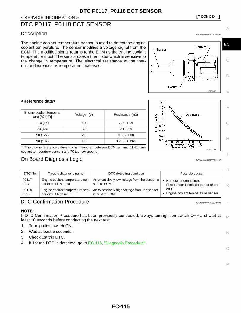
DTC P0117, P0118 ECT SENSOR[YD25DDTi]
C
D
E
F
G
H
I
J
K
L
M
A
C
N
P
O
< SERVICE INFORMATION >
E
DTC P0117, P0118 ECT SENSOR
Description INFOID:0000000003759391
The engine coolant temperature sensor is used to detect the enginecoolant temperature. The sensor modifies a voltage signal from theECM. The modified signal returns to the ECM as the engine coolanttemperature input. The sensor uses a thermistor which is sensitive tothe change in temperature. The electrical resistance of the ther-mistor decreases as temperature increases.
<Reference data>
*: This data is reference values and is measured between ECM terminal 51 (Enginecoolant temperature sensor) and 70 (sensor ground).
On Board Diagnosis Logic INFOID:0000000003759392
DTC Confirmation Procedure INFOID:0000000003759393
NOTE:If DTC Confirmation Procedure has been previously conducted, always turn ignition switch OFF and wait atleast 10 seconds before conducting the next test. 1. Turn ignition switch ON.2. Wait at least 5 seconds.3. Check 1st trip DTC.4. If 1st trip DTC is detected, go to EC-116, "Diagnosis Procedure".
SEF594K
Engine coolant tempera-ture [°C (°F)]
Voltage* (V) Resistance (kΩ)
−10 (14) 4.7 7.0 - 11.4
20 (68) 3.8 2.1 - 2.9
50 (122) 2.6 0.68 - 1.00
90 (194) 1.3 0.236 - 0.260
SEF012P
DTC No. Trouble diagnosis name DTC detecting condition Possible cause
P01170117
Engine coolant temperature sen-sor circuit low input
An excessively low voltage from the sensor is sent to ECM.
• Harness or connectors(The sensor circuit is open or short-ed.)
• Engine coolant temperature sensorP01180118
Engine coolant temperature sen-sor circuit high input
An excessively high voltage from the sensor is sent to ECM.
EC-115
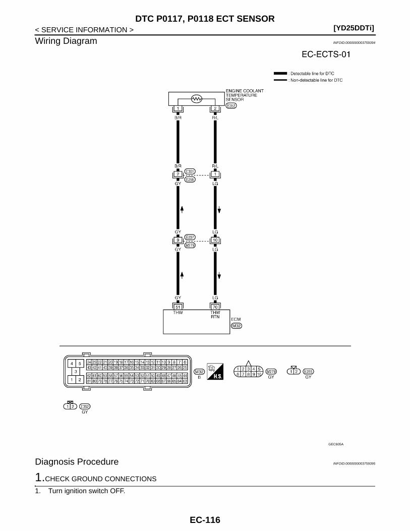
[YD25DDTi]DTC P0117, P0118 ECT SENSOR
< SERVICE INFORMATION >
Wiring Diagram INFOID:0000000003759394
Diagnosis Procedure INFOID:0000000003759395
1.CHECK GROUND CONNECTIONS
1. Turn ignition switch OFF.
GEC605A
EC-116
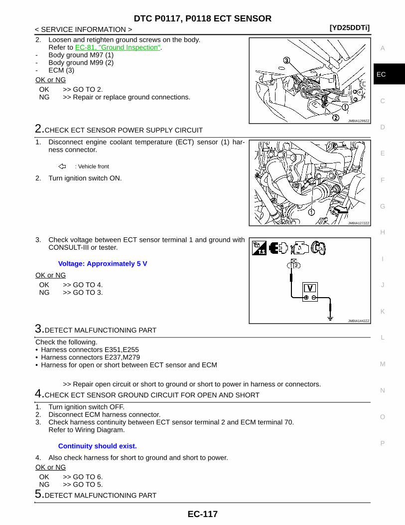
DTC P0117, P0118 ECT SENSOR[YD25DDTi]
C
D
E
F
G
H
I
J
K
L
M
A
C
N
P
O
< SERVICE INFORMATION >
E
2. Loosen and retighten ground screws on the body.Refer to EC-81, "Ground Inspection".
- Body ground M97 (1)- Body ground M99 (2)- ECM (3)OK or NGOK >> GO TO 2.NG >> Repair or replace ground connections.
2.CHECK ECT SENSOR POWER SUPPLY CIRCUIT
1. Disconnect engine coolant temperature (ECT) sensor (1) har-ness connector.
2. Turn ignition switch ON.
3. Check voltage between ECT sensor terminal 1 and ground withCONSULT-III or tester.
OK or NGOK >> GO TO 4.NG >> GO TO 3.
3.DETECT MALFUNCTIONING PART
Check the following.• Harness connectors E351,E255• Harness connectors E237,M279• Harness for open or short between ECT sensor and ECM
>> Repair open circuit or short to ground or short to power in harness or connectors.
4.CHECK ECT SENSOR GROUND CIRCUIT FOR OPEN AND SHORT
1. Turn ignition switch OFF.2. Disconnect ECM harness connector.3. Check harness continuity between ECT sensor terminal 2 and ECM terminal 70.
Refer to Wiring Diagram.
4. Also check harness for short to ground and short to power.OK or NGOK >> GO TO 6.NG >> GO TO 5.
5.DETECT MALFUNCTIONING PART
JMBIA1299ZZ
: Vehicle front
JMBIA1272ZZ
Voltage: Approximately 5 V
JMBIA1442ZZ
Continuity should exist.
EC-117

[YD25DDTi]DTC P0117, P0118 ECT SENSOR
< SERVICE INFORMATION >Check the following.• Harness connectors E351,E255• Harness connectors E237,M279• Harness for open or short between ECT sensor and ECM
>> Repair open circuit or short to ground or short to power in harness or connectors.
6.CHECK ENGINE COOLANT TEMPERATURE SENSOR
Refer to EC-118, "Component Inspection".OK or NGOK >> GO TO 7.NG >> Replace engine coolant temperature sensor.
7.CHECK INTERMITTENT INCIDENT
Refer to EC-70.
>> INSPECTION END
Component Inspection INFOID:0000000003759396
ENGINE COOLANT TEMPERATURE SENSOR1. Check resistance between engine coolant temperature sensor
terminals 1 and 2 as shown in the figure.
2. If NG, replace engine coolant temperature sensor.
Removal and Installation INFOID:0000000003759397
ENGINE COOLANT TEMPERATURE SENSORRefer to “CYLINDER HEAD” in EM section.
JMBIA1443ZZ
Engine coolant temperature [°C (°F)] Resistance (kΩ)
20 (68) 2.1 - 2.9
50 (122) 0.68 - 1.00
90 (194) 0.236 - 0.260
SEF012P
EC-118
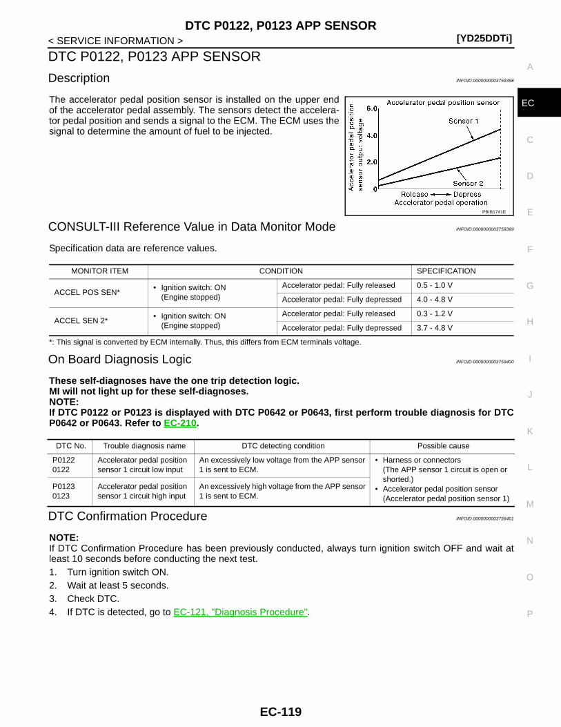
DTC P0122, P0123 APP SENSOR[YD25DDTi]
C
D
E
F
G
H
I
J
K
L
M
A
C
N
P
O
< SERVICE INFORMATION >
E
DTC P0122, P0123 APP SENSOR
Description INFOID:0000000003759398
The accelerator pedal position sensor is installed on the upper endof the accelerator pedal assembly. The sensors detect the accelera-tor pedal position and sends a signal to the ECM. The ECM uses thesignal to determine the amount of fuel to be injected.
CONSULT-III Reference Value in Data Monitor Mode INFOID:0000000003759399
Specification data are reference values.
*: This signal is converted by ECM internally. Thus, this differs from ECM terminals voltage.
On Board Diagnosis Logic INFOID:0000000003759400
These self-diagnoses have the one trip detection logic.MI will not light up for these self-diagnoses.NOTE:If DTC P0122 or P0123 is displayed with DTC P0642 or P0643, first perform trouble diagnosis for DTCP0642 or P0643. Refer to EC-210.
DTC Confirmation Procedure INFOID:0000000003759401
NOTE:If DTC Confirmation Procedure has been previously conducted, always turn ignition switch OFF and wait atleast 10 seconds before conducting the next test. 1. Turn ignition switch ON.2. Wait at least 5 seconds.3. Check DTC.4. If DTC is detected, go to EC-121, "Diagnosis Procedure".
PBIB1741E
MONITOR ITEM CONDITION SPECIFICATION
ACCEL POS SEN*• Ignition switch: ON
(Engine stopped)
Accelerator pedal: Fully released 0.5 - 1.0 V
Accelerator pedal: Fully depressed 4.0 - 4.8 V
ACCEL SEN 2*• Ignition switch: ON
(Engine stopped)
Accelerator pedal: Fully released 0.3 - 1.2 V
Accelerator pedal: Fully depressed 3.7 - 4.8 V
DTC No. Trouble diagnosis name DTC detecting condition Possible cause
P01220122
Accelerator pedal position sensor 1 circuit low input
An excessively low voltage from the APP sensor 1 is sent to ECM.
• Harness or connectors(The APP sensor 1 circuit is open or shorted.)
• Accelerator pedal position sensor(Accelerator pedal position sensor 1)
P01230123
Accelerator pedal position sensor 1 circuit high input
An excessively high voltage from the APP sensor 1 is sent to ECM.
EC-119

[YD25DDTi]DTC P0122, P0123 APP SENSOR
< SERVICE INFORMATION >
Wiring Diagram INFOID:0000000003759402
Specification data are reference values and are measured between each terminal and ground.GEC606A
EC-120

DTC P0122, P0123 APP SENSOR[YD25DDTi]
C
D
E
F
G
H
I
J
K
L
M
A
C
N
P
O
< SERVICE INFORMATION >
E
: Average voltage for pulse signal (Actual pulse signal can be confirmed by oscilloscope.)
Diagnosis Procedure INFOID:0000000003759403
1.CHECK GROUND CONNECTIONS
1. Turn ignition switch OFF.2. Loosen and retighten ground screws on the body.
Refer to EC-81, "Ground Inspection".- Body ground M97 (1)- Body ground M99 (2)- ECM (3)OK or NGOK >> GO TO 2.NG >> Repair or replace ground connections.
2.CHECK APP SENSOR 1 POWER SUPPLY CIRCUIT
TERMINAL NO.(Wire color)
DescriptionCondition
Value (Approx.)
+ − Signal name
67(B)
—Sensor ground(Sensor shield circuit)
— —
82(W)
84(R)
Sensor power supply(Accelerator pedal position sensor 1 / Crankshaft position sensor / EGR volume control valve control position sensor)
[Ignition switch ON] Approximately 5 V
83(B)
84(R)
Accelerator pedal position sensor 1
[Ignition switch ON]• Engine: Stopped• Accelerator pedal: Fully released
0.5 - 1.0 V
[Ignition switch ON]• Engine: Stopped• Accelerator pedal: Fully depressed
3.7 - 4.7 V
84(R)
—Accelerator pedal position sensor 1 ground
— —
90(L)
92(Y)
Accelerator pedal position sensor 2 power supply
[Ignition switch ON] Approximately 5 V
91(G)
92(Y)
Accelerator pedal position sensor 2
[Ignition switch ON]• Engine: Stopped• Accelerator pedal: Fully released
0.15 - 0.6 V
[Ignition switch ON]• Engine: Stopped• Accelerator pedal: Fully depressed
1.85 - 2.4 V
92(Y)
—Accelerator pedal position sensor 2 ground
— —
JMBIA1299ZZ
EC-121
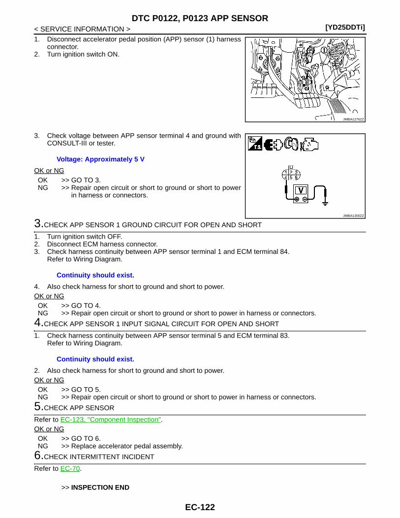
[YD25DDTi]DTC P0122, P0123 APP SENSOR
< SERVICE INFORMATION >1. Disconnect accelerator pedal position (APP) sensor (1) harness
connector.2. Turn ignition switch ON.
3. Check voltage between APP sensor terminal 4 and ground withCONSULT-III or tester.
OK or NGOK >> GO TO 3.NG >> Repair open circuit or short to ground or short to power
in harness or connectors.
3.CHECK APP SENSOR 1 GROUND CIRCUIT FOR OPEN AND SHORT
1. Turn ignition switch OFF.2. Disconnect ECM harness connector.3. Check harness continuity between APP sensor terminal 1 and ECM terminal 84.
Refer to Wiring Diagram.
4. Also check harness for short to ground and short to power.OK or NGOK >> GO TO 4.NG >> Repair open circuit or short to ground or short to power in harness or connectors.
4.CHECK APP SENSOR 1 INPUT SIGNAL CIRCUIT FOR OPEN AND SHORT
1. Check harness continuity between APP sensor terminal 5 and ECM terminal 83.Refer to Wiring Diagram.
2. Also check harness for short to ground and short to power.OK or NGOK >> GO TO 5.NG >> Repair open circuit or short to ground or short to power in harness or connectors.
5.CHECK APP SENSOR
Refer to EC-123, "Component Inspection".OK or NGOK >> GO TO 6.NG >> Replace accelerator pedal assembly.
6.CHECK INTERMITTENT INCIDENT
Refer to EC-70.
>> INSPECTION END
JMBIA1276ZZ
Voltage: Approximately 5 V
JMBIA1300ZZ
Continuity should exist.
Continuity should exist.
EC-122
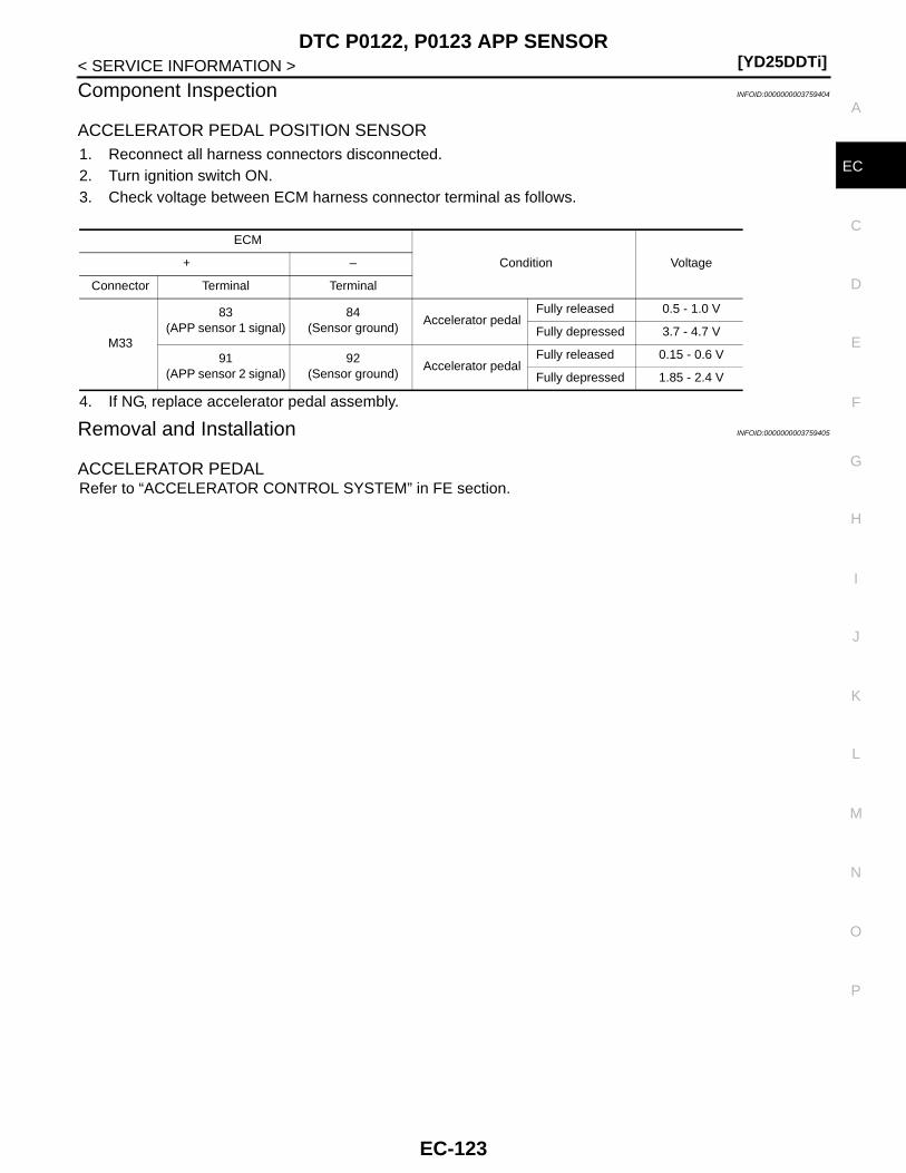
DTC P0122, P0123 APP SENSOR[YD25DDTi]
C
D
E
F
G
H
I
J
K
L
M
A
C
N
P
O
< SERVICE INFORMATION >
E
Component Inspection INFOID:0000000003759404
ACCELERATOR PEDAL POSITION SENSOR1. Reconnect all harness connectors disconnected.2. Turn ignition switch ON.3. Check voltage between ECM harness connector terminal as follows.
4. If NG, replace accelerator pedal assembly.
Removal and Installation INFOID:0000000003759405
ACCELERATOR PEDALRefer to “ACCELERATOR CONTROL SYSTEM” in FE section.
ECM
Condition Voltage+ –
Connector Terminal Terminal
M33
83(APP sensor 1 signal)
84(Sensor ground)
Accelerator pedalFully released 0.5 - 1.0 V
Fully depressed 3.7 - 4.7 V
91(APP sensor 2 signal)
92(Sensor ground)
Accelerator pedalFully released 0.15 - 0.6 V
Fully depressed 1.85 - 2.4 V
EC-123

[YD25DDTi]DTC P0182, P0183 FUEL PUMP TEMPERATURE SENSOR
< SERVICE INFORMATION >
DTC P0182, P0183 FUEL PUMP TEMPERATURE SENSOR
Description INFOID:0000000003759442
Fuel pump temperature sensor (1) is built in the fuel pump (2). Thesensor detects the fuel temperature in the fuel pump and calibratesthe fuel injection amount change by fuel temperature.
CONSULT-III Reference Value in Data Monitor Mode INFOID:0000000003759443
Specification data are reference values.
On Board Diagnosis Logic INFOID:0000000003759444
DTC Confirmation Procedure INFOID:0000000003759445
NOTE:If DTC Confirmation Procedure has been previously conducted, always turn ignition switch OFF and wait atleast 10 seconds before conducting the next test. 1. Turn ignition switch ON.2. Wait at least 5 seconds.3. Check 1st trip DTC.4. If 1st trip DTC is detected, go to EC-125, "Diagnosis Procedure".
MBIB1751E
MONITOR ITEM CONDITION SPECIFICATION
FUEL TEMP SEN • Engine: After warming up More than 40°C (104°F)
DTC No. Trouble diagnosis name DTC detecting condition Possible cause
P01820182
Fuel pump temperature sensor circuit low input
An excessively low voltage from the sensor is sent to ECM.
• Harness or connectors(The sensor circuit is open or short-ed.)
• Fuel pump temperature sensorP01830183
Fuel pump temperature sensor circuit high input
An excessively high voltage from the sensor is sent to ECM.
EC-124

DTC P0182, P0183 FUEL PUMP TEMPERATURE SENSOR[YD25DDTi]
C
D
E
F
G
H
I
J
K
L
M
A
C
N
P
O
< SERVICE INFORMATION >
E
Wiring Diagram INFOID:0000000003759446
Diagnosis Procedure INFOID:0000000003759448
1.CHECK GROUND CONNECTIONS
1. Turn ignition switch OFF.
GEC608A
EC-125

[YD25DDTi]DTC P0182, P0183 FUEL PUMP TEMPERATURE SENSOR
< SERVICE INFORMATION >2. Loosen and retighten ground screws on the body.
Refer to EC-81, "Ground Inspection".- Body ground M97 (1)- Body ground M99 (2)- ECM (3)OK or NGOK >> GO TO 2.NG >> Repair or replace ground connections.
2.CHECK FUEL PUMP TEMPERATURE SENSOR POWER SUPPLY CIRCUIT
1. Disconnect fuel pump temperature sensor (1) harness connec-tor.
- Fuel pump (2)2. Turn ignition switch ON.
3. Check voltage between fuel pump temperature sensor terminal1 and ground with CONSULT-III or tester.
OK or NGOK >> GO TO 4.NG >> GO TO 3.
3.DETECT MALFUNCTIONING PART
Check the following• Harness connectors E237, M279• Harness for open or short between fuel pump temperature sensor and ECM
>> Repair open circuit or short to ground or short to power in harness or connectors.
4.CHECK FUEL PUMP TEMPERATURE SENSOR GROUND CIRCUIT FOR OPEN AND SHORT
1. Turn ignition switch OFF.2. Disconnect ECM harness connector.3. Check harness continuity between fuel pump temperature sensor terminal 2 and ECM terminal 69.
Refer to Wiring Diagram.
4. Also check harness for short to ground and short to power.OK or NGOK >> GO TO 6.NG >> GO TO 5.
5.DETECT MALFUNCTIONING PART
Check the following
JMBIA1299ZZ
MBIB1751E
Voltage: Approximately 5V
PBIB2651E
Continuity should exist.
EC-126
DTC P0182, P0183 FUEL PUMP TEMPERATURE SENSOR[YD25DDTi]
C
D
E
F
G
H
I
J
K
L
M
A
C
N
P
O
< SERVICE INFORMATION >
E
• Harness connectors E237, M279• Harness for open or short between fuel pump temperature sensor and ECM
>> Repair open circuit or short to ground or short to power in harness or connectors.
6.CHECK INTERMITTENT INCIDENT
Refer to EC-70.OK or NGOK >> GO TO 7.NG >> Repair or replace.
7.REPLACE FUEL PUMP
1. Replace fuel pump.2. Perform Fuel Pump Learning Value Clearing. Refer to EC-23, "Fuel Pump Learning Value Clearing".
>> INSPECTION END
Removal and Installation INFOID:0000000003759449
FUEL PUMPRefer to EC-24, "FUEL PUMP".
EC-127

[YD25DDTi]DTC P0192, P0193 FRP SENSOR
< SERVICE INFORMATION >
DTC P0192, P0193 FRP SENSOR
Description INFOID:0000000003759450
The fuel rail pressure (FRP) sensor (2) is placed to the fuel rail. Itmeasures the fuel pressure in the fuel rail. The sensor sends voltagesignal to the ECM. As the pressure increases, the voltage rises. The ECM controls the fuel pressure in the fuel rail by the inlet throt-tling device. The ECM uses the signal from fuel rail pressure sensoras a feedback signal.
• Fuel rail pressure relief valve (1)
CONSULT-III Reference Value in Data Monitor Mode INFOID:0000000003759451
Specification data are reference values.
On Board Diagnosis Logic INFOID:0000000003759452
NOTE:If DTC P0192 or P0193 is displayed with DTC P0652 or P0653, first perform trouble diagnosis for DTCP0652 or P0653. Refer to EC-214.
DTC Confirmation Procedure INFOID:0000000003759453
NOTE:If DTC Confirmation Procedure has been previously conducted, always turn ignition switch OFF and wait atleast 10 seconds before conducting the next test. 1. Turn ignition switch ON.2. Wait at least 5 seconds.3. Check 1st trip DTC.4. If 1st trip DTC is detected, go to EC-130, "Diagnosis Procedure".
: Vehicle front
JMBIA1270ZZ
MONITOR CONDITION SPECIFICATION
ACT CR PRESS
• Engine: After warming up• Air conditioner switch: OFF• Shift lever: Neutral• No load
Idle 25 - 35 MPa
2,000 rpm 40 - 50 MPa
DTC No. Trouble diagnosis name DTC detecting condition Possible cause
P01920192
Fuel rail pressure sensor circuit low input
An excessively low voltage from the sensor is sent to ECM.
• Harness or connectors(The sensor circuit is open or short-ed.)
• Fuel rail temperature sensorP01930193
Fuel rail temperature sen-sor circuit high input
An excessively high voltage from the sensor is sent to ECM.
EC-128
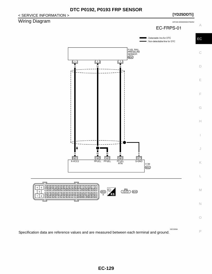
DTC P0192, P0193 FRP SENSOR[YD25DDTi]
C
D
E
F
G
H
I
J
K
L
M
A
C
N
P
O
< SERVICE INFORMATION >
E
Wiring Diagram INFOID:0000000003759454
Specification data are reference values and are measured between each terminal and ground.GEC609A
EC-129
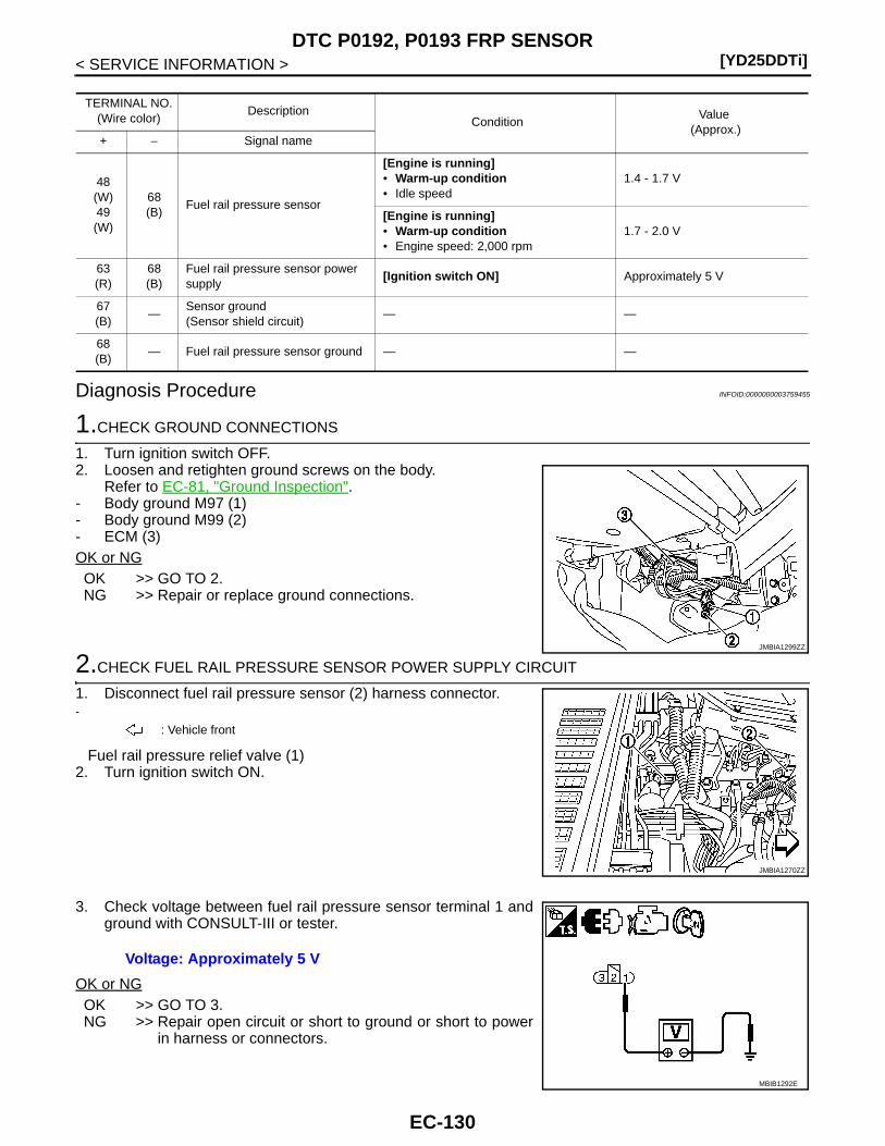
[YD25DDTi]DTC P0192, P0193 FRP SENSOR
< SERVICE INFORMATION >
Diagnosis Procedure INFOID:0000000003759455
1.CHECK GROUND CONNECTIONS
1. Turn ignition switch OFF.2. Loosen and retighten ground screws on the body.
Refer to EC-81, "Ground Inspection".- Body ground M97 (1)- Body ground M99 (2)- ECM (3)OK or NGOK >> GO TO 2.NG >> Repair or replace ground connections.
2.CHECK FUEL RAIL PRESSURE SENSOR POWER SUPPLY CIRCUIT
1. Disconnect fuel rail pressure sensor (2) harness connector.-
Fuel rail pressure relief valve (1)2. Turn ignition switch ON.
3. Check voltage between fuel rail pressure sensor terminal 1 andground with CONSULT-III or tester.
OK or NGOK >> GO TO 3.NG >> Repair open circuit or short to ground or short to power
in harness or connectors.
TERMINAL NO.(Wire color)
DescriptionCondition
Value (Approx.)
+ − Signal name
48(W)49(W)
68(B)
Fuel rail pressure sensor
[Engine is running]• Warm-up condition• Idle speed
1.4 - 1.7 V
[Engine is running]• Warm-up condition• Engine speed: 2,000 rpm
1.7 - 2.0 V
63(R)
68(B)
Fuel rail pressure sensor power supply
[Ignition switch ON] Approximately 5 V
67(B)
—Sensor ground(Sensor shield circuit)
— —
68(B)
— Fuel rail pressure sensor ground — —
JMBIA1299ZZ
: Vehicle front
JMBIA1270ZZ
Voltage: Approximately 5 V
MBIB1292E
EC-130
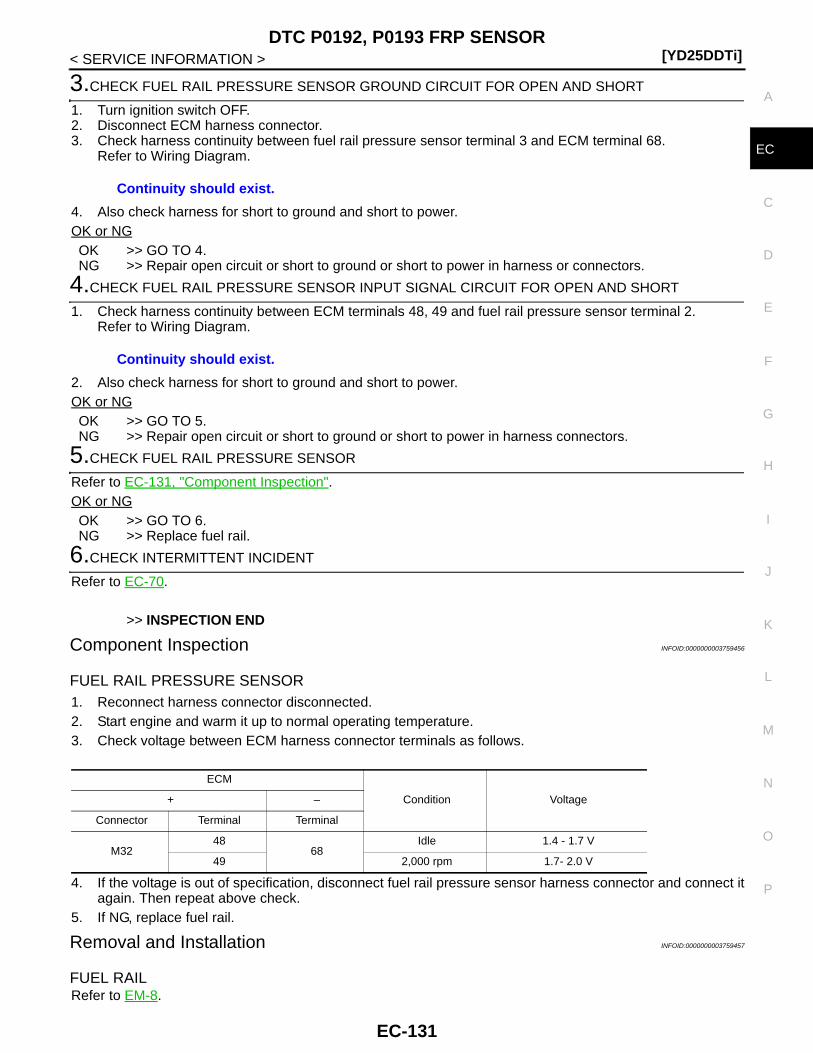
DTC P0192, P0193 FRP SENSOR[YD25DDTi]
C
D
E
F
G
H
I
J
K
L
M
A
C
N
P
O
< SERVICE INFORMATION >
E
3.CHECK FUEL RAIL PRESSURE SENSOR GROUND CIRCUIT FOR OPEN AND SHORT
1. Turn ignition switch OFF.2. Disconnect ECM harness connector.3. Check harness continuity between fuel rail pressure sensor terminal 3 and ECM terminal 68.
Refer to Wiring Diagram.
4. Also check harness for short to ground and short to power.OK or NGOK >> GO TO 4.NG >> Repair open circuit or short to ground or short to power in harness or connectors.
4.CHECK FUEL RAIL PRESSURE SENSOR INPUT SIGNAL CIRCUIT FOR OPEN AND SHORT
1. Check harness continuity between ECM terminals 48, 49 and fuel rail pressure sensor terminal 2.Refer to Wiring Diagram.
2. Also check harness for short to ground and short to power.OK or NGOK >> GO TO 5.NG >> Repair open circuit or short to ground or short to power in harness connectors.
5.CHECK FUEL RAIL PRESSURE SENSOR
Refer to EC-131, "Component Inspection".OK or NGOK >> GO TO 6.NG >> Replace fuel rail.
6.CHECK INTERMITTENT INCIDENT
Refer to EC-70.
>> INSPECTION END
Component Inspection INFOID:0000000003759456
FUEL RAIL PRESSURE SENSOR1. Reconnect harness connector disconnected.2. Start engine and warm it up to normal operating temperature.3. Check voltage between ECM harness connector terminals as follows.
4. If the voltage is out of specification, disconnect fuel rail pressure sensor harness connector and connect itagain. Then repeat above check.
5. If NG, replace fuel rail.
Removal and Installation INFOID:0000000003759457
FUEL RAILRefer to EM-8.
Continuity should exist.
Continuity should exist.
ECM
Condition Voltage + –
Connector Terminal Terminal
M3248
68Idle 1.4 - 1.7 V
49 2,000 rpm 1.7- 2.0 V
EC-131

[YD25DDTi]DTC P0200 FUEL INJECTOR
< SERVICE INFORMATION >
DTC P0200 FUEL INJECTOR
On Board Diagnosis Logic INFOID:0000000003759458
DTC Confirmation Procedure INFOID:0000000003759459
NOTE:If DTC Confirmation Procedure has been previously conducted, always turn ignition switch OFF and wait atleast 10 seconds before conducting the next test. 1. Start engine and let it idle for at least 5 seconds.2. Check 1st trip DTC.3. If 1st trip DTC is detected, go to EC-132, "Diagnosis Procedure".
Diagnosis Procedure INFOID:0000000003759460
1.INSPECTION START
With CONSULT-III1. Turn ignition switch ON.2. Select “SELF DIAG RESULTS” mode with CONSULT-III.3. Touch “ERASE”.4. Perform EC-132, "DTC Confirmation Procedure", again.5. Is 1st trip DTC P0200 displayed again?
With GST1. Turn ignition switch ON.2. Select Service $04 with GST.3. Perform EC-132, "DTC Confirmation Procedure", again.4. Is 1st trip DTC P0200 displayed again?Yes or NoYes >> GO TO 2.No >> INSPECTION END
2.REPLACE ECM
1. Replace ECM.2. Perform initialization of NATS system and registration of all NATS ignition key IDs. Refer to EL-96, "ECM
Re-communicating Function".3. Perform Injector Adjustment Value Registration. Refer to EC-22, "Injector Adjustment Value Registration".4. Perform Fuel Pump Learning Value Clearing. Refer to EC-23, "Fuel Pump Learning Value Clearing".5. Perform EGR Volume Control Valve Closed Position Learning Value Clear. Refer to EC-24, "EGR Volume
Control Valve Closed Position Learning Value Clear".6. Perform EGR Volume Control Valve Closed Position Learning. Refer to EC-24, "EGR Volume Control
Valve Closed Position Learning".
>> INSPECTION END
DTC No. Trouble diagnosis name DTC detecting condition Possible cause
P02000200
Fuel injector power supply circuit
ECM detects a voltage of power source for the fuel injector is excessively high or low.
• ECM
EC-132

DTC P0201 - P0204 FUEL INJECTOR[YD25DDTi]
C
D
E
F
G
H
I
J
K
L
M
A
C
N
P
O
< SERVICE INFORMATION >
E
DTC P0201 - P0204 FUEL INJECTOR
Component Description INFOID:0000000003759461
The fuel injector is a small, precise solenoid valve. When the ECMsupplies a ground to the fuel injector circuit, the coil in the fuel injec-tor is energized. The energized coil pulls the needle valve back andallows fuel to flow through the fuel injector into the cylinder. Theamount of fuel injected depends upon the injection pulse duration.Pulse duration is the length of time the fuel injector remains open.The ECM controls the injection pulse duration based on engine fuelneeds.
CONSULT-III Reference Value in Data Monitor Mode INFOID:0000000003759462
Specification data are reference values.
On Board Diagnosis Logic INFOID:0000000003759463
DTC Confirmation Procedure INFOID:0000000003759464
NOTE:If DTC Confirmation Procedure has been previously conducted, always turn ignition switch OFF and wait atleast 10 seconds before conducting the next test. TESTING CONDITIONBefore performing the following procedure, confirm the ambient temperature is more than -20°C (-4°F).1. Start engine and let it idle for at least 5 seconds.2. Check 1st trip DTC.3. If 1st trip DTC is detected, go to EC-136, "Diagnosis Procedure".
PBIB0465E
MONITOR ITEM CONDITION SPECIFICATION
MAIN INJ WID• Engine: After warming up• Shift lever: Neutral position• Idle speed
No load 0.68 - 0.78 msec
Blower fan switch: ON 0.78 - 0.88 msec
DTC No. Trouble diagnosis name DTC detecting condition Possible cause
P02010201
No. 1 cylinder fuel injector circuit open
An improper voltage signal is sent to ECM through No. 1 cylinder fuel injector.
• Harness or connectors(The fuel injector circuit is open.)
• Fuel injector
P02020202
No. 2 cylinder fuel injector circuit open
An improper voltage signal is sent to ECM through No. 2 cylinder fuel injector.
P02030203
No. 3 cylinder fuel injector circuit open
An improper voltage signal is sent to ECM through No. 3 cylinder fuel injector.
P02040204
No. 4 cylinder fuel injector circuit open
An improper voltage signal is sent to ECM through No. 4 cylinder fuel injector.
EC-133
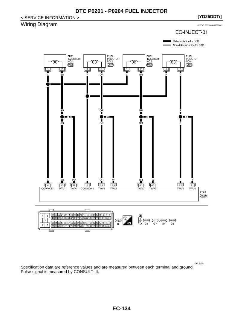
[YD25DDTi]DTC P0201 - P0204 FUEL INJECTOR
< SERVICE INFORMATION >
Wiring Diagram INFOID:0000000003759465
Specification data are reference values and are measured between each terminal and ground.Pulse signal is measured by CONSULT-III.
GEC610A
EC-134
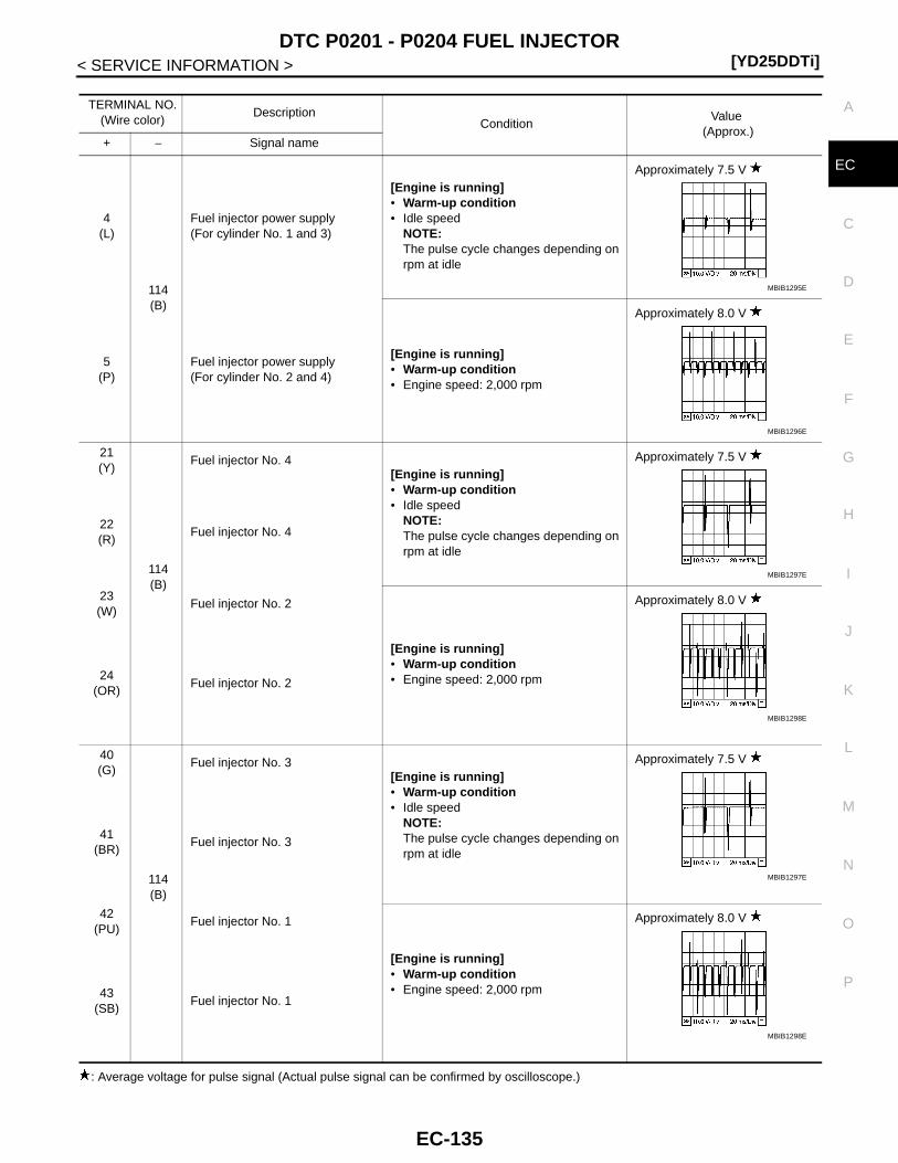
DTC P0201 - P0204 FUEL INJECTOR[YD25DDTi]
C
D
E
F
G
H
I
J
K
L
M
A
C
N
P
O
< SERVICE INFORMATION >
E
: Average voltage for pulse signal (Actual pulse signal can be confirmed by oscilloscope.)
TERMINAL NO.(Wire color)
DescriptionCondition
Value (Approx.)
+ − Signal name
4(L)
114(B)
Fuel injector power supply(For cylinder No. 1 and 3)
[Engine is running]• Warm-up condition• Idle speed
NOTE:The pulse cycle changes depending on rpm at idle
Approximately 7.5 V
5(P)
Fuel injector power supply(For cylinder No. 2 and 4)
[Engine is running]• Warm-up condition• Engine speed: 2,000 rpm
Approximately 8.0 V
21(Y)
114(B)
Fuel injector No. 4[Engine is running]• Warm-up condition• Idle speed
NOTE:The pulse cycle changes depending on rpm at idle
Approximately 7.5 V
22(R)
Fuel injector No. 4
23(W)
Fuel injector No. 2
[Engine is running]• Warm-up condition• Engine speed: 2,000 rpm
Approximately 8.0 V
24(OR)
Fuel injector No. 2
40(G)
114(B)
Fuel injector No. 3[Engine is running]• Warm-up condition• Idle speed
NOTE:The pulse cycle changes depending on rpm at idle
Approximately 7.5 V
41(BR)
Fuel injector No. 3
42(PU)
Fuel injector No. 1
[Engine is running]• Warm-up condition• Engine speed: 2,000 rpm
Approximately 8.0 V
43(SB)
Fuel injector No. 1
MBIB1295E
MBIB1296E
MBIB1297E
MBIB1298E
MBIB1297E
MBIB1298E
EC-135
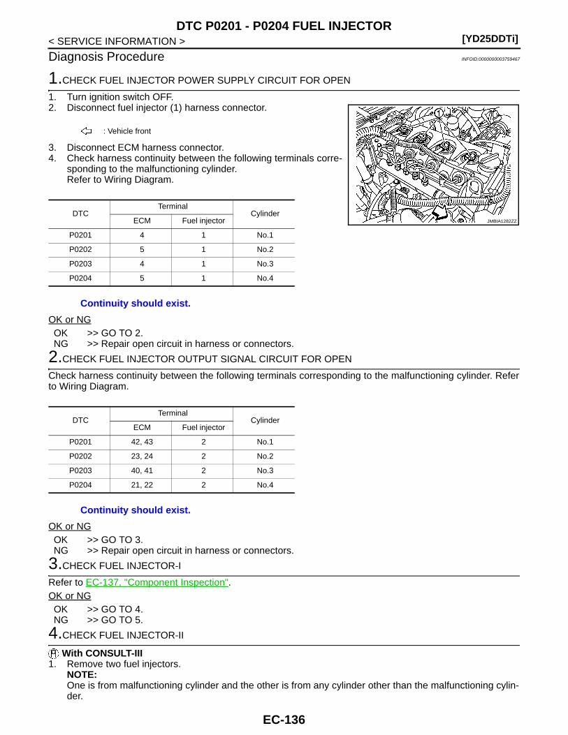
[YD25DDTi]DTC P0201 - P0204 FUEL INJECTOR
< SERVICE INFORMATION >
Diagnosis Procedure INFOID:0000000003759467
1.CHECK FUEL INJECTOR POWER SUPPLY CIRCUIT FOR OPEN
1. Turn ignition switch OFF.2. Disconnect fuel injector (1) harness connector.
3. Disconnect ECM harness connector.4. Check harness continuity between the following terminals corre-
sponding to the malfunctioning cylinder.Refer to Wiring Diagram.
OK or NGOK >> GO TO 2.NG >> Repair open circuit in harness or connectors.
2.CHECK FUEL INJECTOR OUTPUT SIGNAL CIRCUIT FOR OPEN
Check harness continuity between the following terminals corresponding to the malfunctioning cylinder. Referto Wiring Diagram.
OK or NGOK >> GO TO 3.NG >> Repair open circuit in harness or connectors.
3.CHECK FUEL INJECTOR-I
Refer to EC-137, "Component Inspection".OK or NGOK >> GO TO 4.NG >> GO TO 5.
4.CHECK FUEL INJECTOR-II
With CONSULT-III1. Remove two fuel injectors.
NOTE:One is from malfunctioning cylinder and the other is from any cylinder other than the malfunctioning cylin-der.
: Vehicle front
DTCTerminal
CylinderECM Fuel injector
P0201 4 1 No.1
P0202 5 1 No.2
P0203 4 1 No.3
P0204 5 1 No.4
Continuity should exist.
JMBIA1282ZZ
DTCTerminal
CylinderECM Fuel injector
P0201 42, 43 2 No.1
P0202 23, 24 2 No.2
P0203 40, 41 2 No.3
P0204 21, 22 2 No.4
Continuity should exist.
EC-136

DTC P0201 - P0204 FUEL INJECTOR[YD25DDTi]
C
D
E
F
G
H
I
J
K
L
M
A
C
N
P
O
< SERVICE INFORMATION >
E
2. Swap the two fuel injectors to the other cylinder.3. Reconnect ECM harness connector and fuel injector harness connectors.4. Turn ignition switch ON.5. Perform Injector Adjustment Value Registration. Refer to EC-22, "Injector Adjustment Value Registration".6. Select “SELF DIAG RESULTS” mode with CONSULT-III.7. Touch “ERASE”.8. Perform EC-133, "DTC Confirmation Procedure".9. Is DTC displayed for the other cylinder?
With GST1. Remove two fuel injectors.
NOTE:One is from malfunctioning cylinder and the other is from any cylinder other than the malfunctioning cylin-der.
2. Swap the two fuel injectors to the other cylinder.3. Reconnect ECM harness connector and fuel injector harness connector.4. Turn ignition switch ON.5. Perform Injector Adjustment Value Registration. Refer to EC-22, "Injector Adjustment Value Registration".6. Select Service $04 with GST.7. Perform EC-133, "DTC Confirmation Procedure".8. Is DTC displayed for the other cylinder?Yes or NoYes >> GO TO 5.No >> GO TO 6.
5.REPLACE FUEL INJECTOR
1. Replace fuel injector of malfunctioning cylinder.2. Perform Injector Adjustment Value Registration. Refer to EC-22, "Injector Adjustment Value Registration".
>> INSPECTION END
6.CHECK INTERMITTENT INCIDENT
Refer to EC-70.
>> INSPECTION END
Component Inspection INFOID:0000000003759468
FUEL INJECTOR1. Disconnect fuel injector harness connector.2. Check resistance between terminals as shown in the figure.
3. If NG, replace fuel injector.
Removal and Installation INFOID:0000000003759469
FUEL INJECTORRefer to EM-8.
Resistance: 0.2 - 0.8 Ω [at 10 - 60°C (50 - 140°F)]
MBIB1735E
EC-137
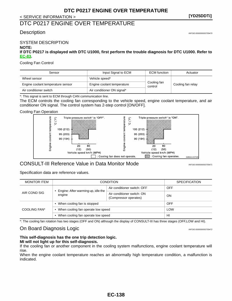
[YD25DDTi]DTC P0217 ENGINE OVER TEMPERATURE
< SERVICE INFORMATION >
DTC P0217 ENGINE OVER TEMPERATURE
Description INFOID:0000000003759470
SYSTEM DESCRIPTIONNOTE:If DTC P0217 is displayed with DTC U1000, first perform the trouble diagnosis for DTC U1000. Refer toEC-83.
Cooling Fan Control
*: This signal is sent to ECM through CAN communication line.
The ECM controls the cooling fan corresponding to the vehicle speed, engine coolant temperature, and airconditioner ON signal. The control system has 2-step control [ON/OFF].
Cooling Fan Operation
CONSULT-III Reference Value in Data Monitor Mode INFOID:0000000003759471
Specification data are reference values.
*: The cooling fan rotation has two stages (OFF and ON) although the display of CONSULT-III has three stages (OFF,LOW and HI).
On Board Diagnosis Logic INFOID:0000000003759472
This self-diagnosis has the one trip detection logic.MI will not light up for this self-diagnosis.If the cooling fan or another component in the cooling system malfunctions, engine coolant temperature willrise.When the engine coolant temperature reaches an abnormally high temperature condition, a malfunction isindicated.
Sensor Input Signal to ECM ECM function Actuator
Wheel sensor Vehicle speed*Cooling fan control
Cooling fan relayEngine coolant temperature sensor Engine coolant temperature
Air conditioner switch Air conditioner ON signal*
JMBIA1437GB
MONITOR ITEM CONDITION SPECIFICATION
AIR COND SIG• Engine: After warming up, idle the
engine
Air conditioner switch: OFF OFF
Air conditioner switch: ON(Compressor operates)
ON
COOLING FAN*
• When cooling fan is stopped OFF
• When cooling fan operate low speed LOW
• When cooling fan operate low speed HI
EC-138
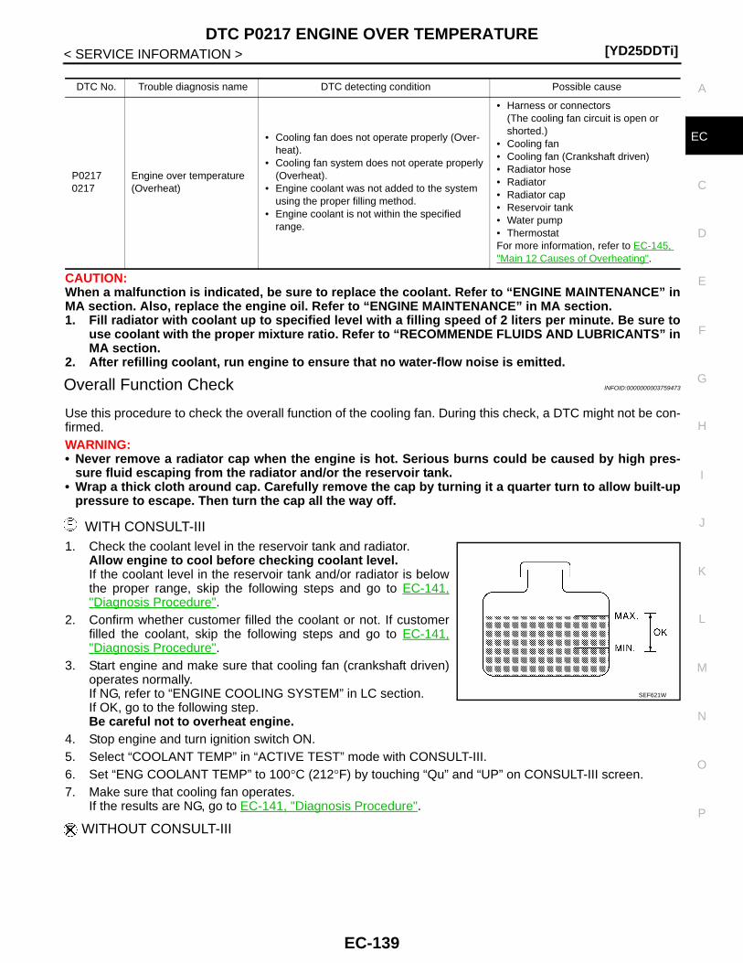
DTC P0217 ENGINE OVER TEMPERATURE[YD25DDTi]
C
D
E
F
G
H
I
J
K
L
M
A
C
N
P
O
< SERVICE INFORMATION >
E
CAUTION:When a malfunction is indicated, be sure to replace the coolant. Refer to “ENGINE MAINTENANCE” inMA section. Also, replace the engine oil. Refer to “ENGINE MAINTENANCE” in MA section.1. Fill radiator with coolant up to specified level with a filling speed of 2 liters per minute. Be sure to
use coolant with the proper mixture ratio. Refer to “RECOMMENDE FLUIDS AND LUBRICANTS” inMA section.
2. After refilling coolant, run engine to ensure that no water-flow noise is emitted.
Overall Function Check INFOID:0000000003759473
Use this procedure to check the overall function of the cooling fan. During this check, a DTC might not be con-firmed.WARNING:• Never remove a radiator cap when the engine is hot. Serious burns could be caused by high pres-
sure fluid escaping from the radiator and/or the reservoir tank.• Wrap a thick cloth around cap. Carefully remove the cap by turning it a quarter turn to allow built-up
pressure to escape. Then turn the cap all the way off.
WITH CONSULT-III1. Check the coolant level in the reservoir tank and radiator.
Allow engine to cool before checking coolant level.If the coolant level in the reservoir tank and/or radiator is belowthe proper range, skip the following steps and go to EC-141,"Diagnosis Procedure".
2. Confirm whether customer filled the coolant or not. If customerfilled the coolant, skip the following steps and go to EC-141,"Diagnosis Procedure".
3. Start engine and make sure that cooling fan (crankshaft driven)operates normally.If NG, refer to “ENGINE COOLING SYSTEM” in LC section.If OK, go to the following step.Be careful not to overheat engine.
4. Stop engine and turn ignition switch ON.5. Select “COOLANT TEMP” in “ACTIVE TEST” mode with CONSULT-III.6. Set “ENG COOLANT TEMP” to 100°C (212°F) by touching “Qu” and “UP” on CONSULT-III screen.7. Make sure that cooling fan operates.
If the results are NG, go to EC-141, "Diagnosis Procedure".
WITHOUT CONSULT-III
DTC No. Trouble diagnosis name DTC detecting condition Possible cause
P02170217
Engine over temperature (Overheat)
• Cooling fan does not operate properly (Over-heat).
• Cooling fan system does not operate properly (Overheat).
• Engine coolant was not added to the system using the proper filling method.
• Engine coolant is not within the specified range.
• Harness or connectors(The cooling fan circuit is open or shorted.)
• Cooling fan• Cooling fan (Crankshaft driven)• Radiator hose• Radiator• Radiator cap• Reservoir tank• Water pump• ThermostatFor more information, refer to EC-145, "Main 12 Causes of Overheating".
SEF621W
EC-139
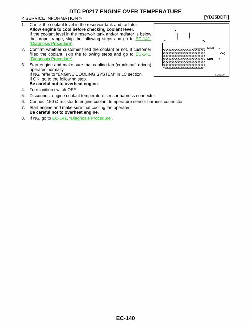
[YD25DDTi]DTC P0217 ENGINE OVER TEMPERATURE
< SERVICE INFORMATION >1. Check the coolant level in the reservoir tank and radiator.
Allow engine to cool before checking coolant level.If the coolant level in the reservoir tank and/or radiator is belowthe proper range, skip the following steps and go to EC-141,"Diagnosis Procedure".
2. Confirm whether customer filled the coolant or not. If customerfilled the coolant, skip the following steps and go to EC-141,"Diagnosis Procedure".
3. Start engine and make sure that cooling fan (crankshaft driven)operates normally.If NG, refer to “ENGINE COOLING SYSTEM” in LC section.If OK, go to the following step.Be careful not to overheat engine.
4. Turn ignition switch OFF.5. Disconnect engine coolant temperature sensor harness connector.6. Connect 150 Ω resistor to engine coolant temperature sensor harness connector.7. Start engine and make sure that cooling fan operates.
Be careful not to overheat engine.8. If NG, go to EC-141, "Diagnosis Procedure".
SEF621W
EC-140
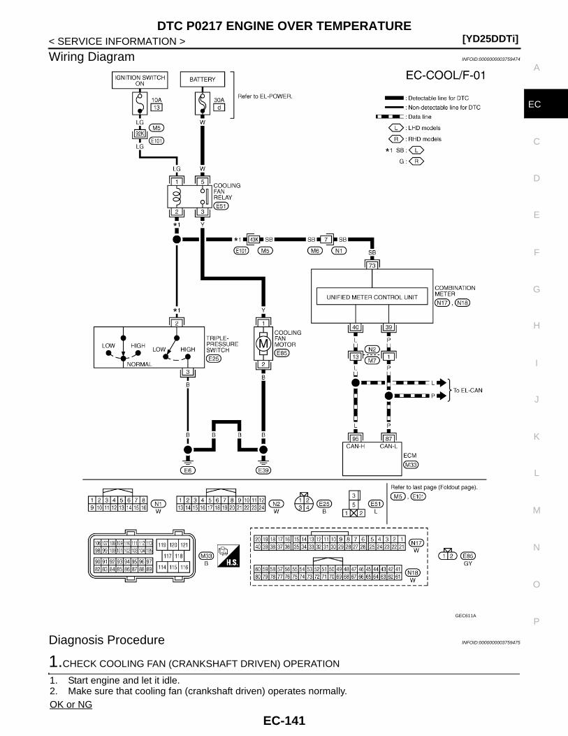
DTC P0217 ENGINE OVER TEMPERATURE[YD25DDTi]
C
D
E
F
G
H
I
J
K
L
M
A
C
N
P
O
< SERVICE INFORMATION >
E
Wiring Diagram INFOID:0000000003759474
Diagnosis Procedure INFOID:0000000003759475
1.CHECK COOLING FAN (CRANKSHAFT DRIVEN) OPERATION
1. Start engine and let it idle.2. Make sure that cooling fan (crankshaft driven) operates normally.OK or NG
GEC611A
EC-141
[YD25DDTi]DTC P0217 ENGINE OVER TEMPERATURE
< SERVICE INFORMATION >OK (With CONSULT-III)>>GO TO 2.OK (Without CONSULT-III)>>GO TO 3.NG >> Check cooling fan (crankshaft driven). Refer to “ENGINE COOLING SYSTEM” in LC section.
2.CHECK COOLING FAN OPERATION
With CONSULT-III1. Start engine and let it idle.2. Select “ENG COOLANT TEMP” in “ACTIVE TEST” mode with CONSULT-III.3. Set “ENG COOLANT TEMP” to 95°C (203°by “Qu” and “UP” on CONSULT-III screen.4. Make sure that cooling fan operate.OK or NGOK >> GO TO 4.NG >> Check cooling fan control circuit. (Go to “PROCEDURE A”.)
3.CHECK COOLING FAN OPERATION
Without CONSULT-III1. Turn ignition switch OFF2. Disconnect engine coolant temperature sensor harness connector.3. Connect 150 Ω resistor to engine coolant temperature sensor harness connector.4. Start engine and make sure that cooling fan operates.OK or NGOK >> GO TO 4.NG >> Check cooling fan control circuit. (Go to “PROCEDURE A”.)
4.CHECK COOLING SYSTEM FOR LEAK
Apply pressure to the cooling system with a tester, and check if the pressure drops. Refer to “ENGINE COOL-ING SYSTEM” in LC section.CAUTION:Higher than the specified pressure may cause radiator damage.Pressure should not drop.OK or NGOK >> GO TO 5.NG >> Check the following for leak. Refer to “ENGINE COOLING SYSTEM” in LC section.
• Hose• Radiator• Radiator cap• Water pump• Reservoir tank
5.CHECK COMPONENT PARTS
Check the following.• Thermostat. Refer to “ENGINE COOLING SYSTEM” in LC section.• Engine coolant temperature sensor. Refer to EC-118, "Component Inspection".OK or NGOK >> GO TO 6.NG >> Replace malfunctioning component.
6.CHECK MAIN 12 CAUSES
If the cause cannot be isolated, go to EC-145, "Main 12 Causes of Overheating".
>> INSPECTION END
PROCEDURE A
1.CHECK COOLING FAN POWER SUPPLY CIRCUIT
1. Turn ignition switch OFF.2. Disconnect cooling fan relay E51.3. Turn ignition switch ON.
EC-142
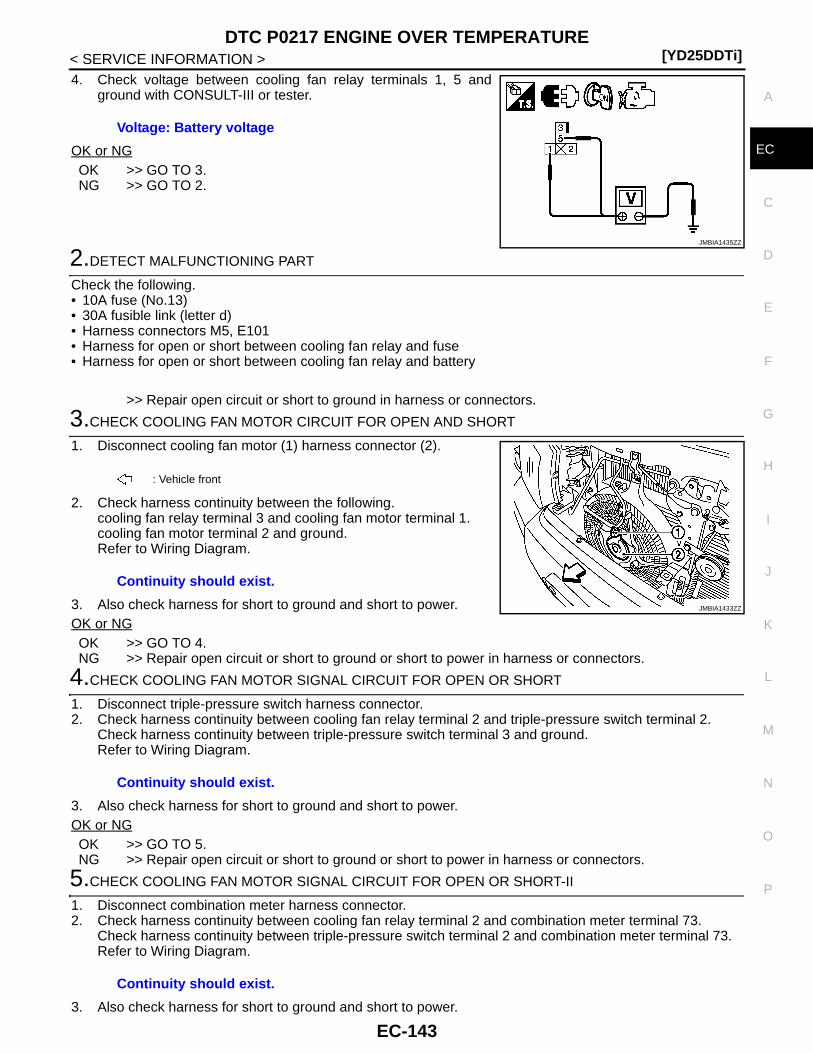
DTC P0217 ENGINE OVER TEMPERATURE[YD25DDTi]
C
D
E
F
G
H
I
J
K
L
M
A
C
N
P
O
< SERVICE INFORMATION >
E
4. Check voltage between cooling fan relay terminals 1, 5 andground with CONSULT-III or tester.
OK or NGOK >> GO TO 3.NG >> GO TO 2.
2.DETECT MALFUNCTIONING PART
Check the following.• 10A fuse (No.13)• 30A fusible link (letter d)• Harness connectors M5, E101• Harness for open or short between cooling fan relay and fuse• Harness for open or short between cooling fan relay and battery
>> Repair open circuit or short to ground in harness or connectors.
3.CHECK COOLING FAN MOTOR CIRCUIT FOR OPEN AND SHORT
1. Disconnect cooling fan motor (1) harness connector (2).
2. Check harness continuity between the following.cooling fan relay terminal 3 and cooling fan motor terminal 1.cooling fan motor terminal 2 and ground.Refer to Wiring Diagram.
3. Also check harness for short to ground and short to power.OK or NGOK >> GO TO 4.NG >> Repair open circuit or short to ground or short to power in harness or connectors.
4.CHECK COOLING FAN MOTOR SIGNAL CIRCUIT FOR OPEN OR SHORT
1. Disconnect triple-pressure switch harness connector. 2. Check harness continuity between cooling fan relay terminal 2 and triple-pressure switch terminal 2.
Check harness continuity between triple-pressure switch terminal 3 and ground.Refer to Wiring Diagram.
3. Also check harness for short to ground and short to power.OK or NGOK >> GO TO 5.NG >> Repair open circuit or short to ground or short to power in harness or connectors.
5.CHECK COOLING FAN MOTOR SIGNAL CIRCUIT FOR OPEN OR SHORT-II
1. Disconnect combination meter harness connector. 2. Check harness continuity between cooling fan relay terminal 2 and combination meter terminal 73.
Check harness continuity between triple-pressure switch terminal 2 and combination meter terminal 73.Refer to Wiring Diagram.
3. Also check harness for short to ground and short to power.
Voltage: Battery voltage
JMBIA1435ZZ
: Vehicle front
Continuity should exist.
JMBIA1433ZZ
Continuity should exist.
Continuity should exist.
EC-143
[YD25DDTi]DTC P0217 ENGINE OVER TEMPERATURE
< SERVICE INFORMATION >OK or NGOK >> GO TO 7.NG >> GO TO 6.
6.DETECT MALFUNCTIONING PART
Check the following.• Harness connectors E101, M5• Harness connectors M6, N1• Harness for open or short between cooling fan relay and combination meter
>> Repair open circuit or short to ground or short to power in harness or connectors.
7.CHECK COOLING FAN MOTOR SIGNAL CIRCUIT FOR OPEN OR SHORT-III
Check harness continuity between Combination Meter and ECM.Refer to EL-117, "Main Line Between ECM and Combination Meter".OK or NGOK >> GO TO 8.NG >> Repair the main line between the ECM and combination meter.
8.CHECK COOLING FAN RELAY
Refer to EC-145, "Component Inspection".OK or NGOK >> GO TO 9.NG >> Replace cooling fan relay.
9.CHECK TRIPLE-PRESSURE SWITCH
Refer to “Electrical Components Inspection” in HA section.OK or NGOK >> GO TO 10.NG >> Replace cooling fan relay.
10.CHECK COOLING FAN MOTOR
Refer to EC-145, "Component Inspection".OK or NGOK >> GO TO 11.NG >> Replace cooling fan motors.
11.CHECK COMBINATION METER
Refer to EL-54, "Self-Diagnosis Mode of Combination meter".OK or NGOK >> GO TO 12.NG >> Replace cooling fan motors.
12.CHECK INTERMITTENT INCIDENT
Refer to EC-70.
>> INSPECTION END
EC-144

DTC P0217 ENGINE OVER TEMPERATURE[YD25DDTi]
C
D
E
F
G
H
I
J
K
L
M
A
C
N
P
O
< SERVICE INFORMATION >
E
Main 12 Causes of Overheating INFOID:0000000003759476
*1: Turn the ignition switch ON.
*2: Engine running at 3,000 rpm for 10 minutes.
*3: Drive at 90 km/h (56 MPH) for 30 minutes and then let idle for 10 minutes.
*4: After 60 minutes of cool down time.
For more information, refer to “OVERHEATING ANALYSIS” in LC section.
Component Inspection INFOID:0000000003759477
COOLING FAN RELAY1. Disconnect cooling fan relay harness connectors.2. Supply cooling fan motor terminals with battery voltage and
check operation.
If NG, replace cooling fan relay.
Engine Step Inspection item Equipment Standard Reference page
OFF 1 • Blocked radiator• Blocked condenser• Blocked radiator grille• Blocked bumper
• Visual No blocking —
2 • Coolant mixture • Coolant tester 50 - 50% coolant mixture See “RECOMMENDED AND LUBRICANTS” in MA section.
3 • Coolant level • Visual Coolant up to MAX level in reservoir tank and radiator filler neck
See “ENGINE MAINTE-NANCE” in MA section.
4 • Radiator cap • Pressure tester See “ENGINE COOLING SYSTEM” in LC section.
ON*2 5 • Coolant leaks • Visual No leaks See “ENGINE COOLING SYSTEM” in LC section.
ON*2 6 • Thermostat • Touch the upper and lower radiator hoses
Both hoses should be hot See “ENGINE COOLING SYSTEM” in LC section.
ON*1 7 • Cooling fan • CONSULT-III Operating See trouble diagnosis for DTC P0217 (EC-138).
ON*2 7• Cooling fan (Crankshaft
driven)• Visual
Operating See “ENGINE COOLING SYSTEM” in LC section.
OFF 8 • Combustion gas leak • Color checker chemical tester 4 Gas analyzer
Negative —
ON*3 9 • Coolant temperature gauge
• Visual Gauge less than 3/4 when driving
—
• Coolant overflow to res-ervoir tank
• Visual No overflow during driving and idling
See “ENGINE MAINTE-NANCE” in MA section.
OFF*4 10 • Coolant return from res-ervoir tank to radiator
• Visual Should be initial level in reservoir tank
See “ENGINE MAINTE-NANCE” in MA section.
OFF 11 • Cylinder head • Straight gauge feeler gauge
0.1 mm (0.004 in) Maxi-mum distortion (warping)
See “CYLINDER HEAD” in EM section.
12 • Cylinder block and pis-tons
• Visual No scuffing on cylinder walls or piston
See “CYLINDER BLOCK” in EM section.
Terminals Conditions Continuity
3 and 512 V direct current supply between terminals 1 and 2 Existed
No current supply Not existed
PBIB0098E
EC-145
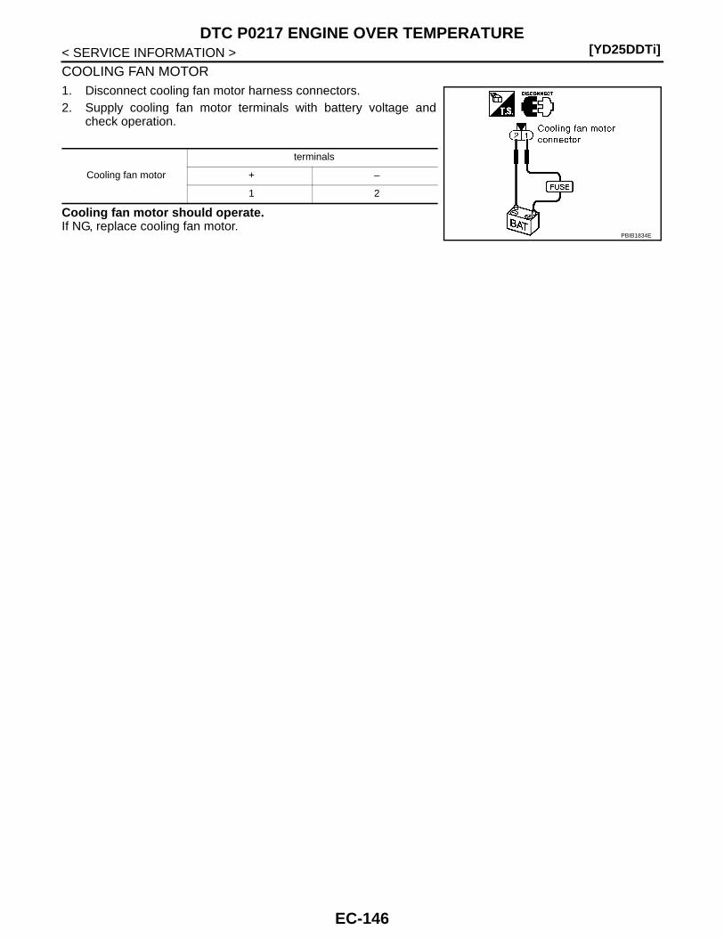
[YD25DDTi]DTC P0217 ENGINE OVER TEMPERATURE
< SERVICE INFORMATION >
COOLING FAN MOTOR1. Disconnect cooling fan motor harness connectors.2. Supply cooling fan motor terminals with battery voltage and
check operation.
Cooling fan motor should operate.If NG, replace cooling fan motor.
Cooling fan motor
terminals
+ –
1 2
PBIB1834E
EC-146
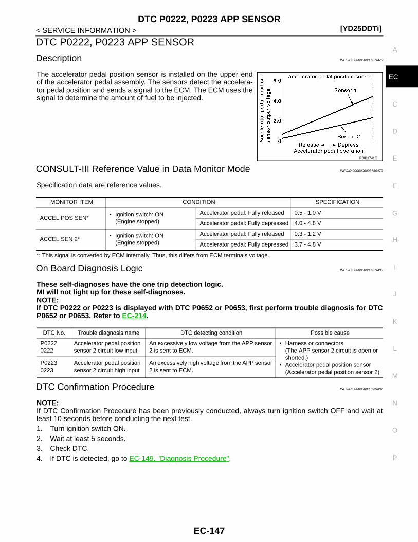
DTC P0222, P0223 APP SENSOR[YD25DDTi]
C
D
E
F
G
H
I
J
K
L
M
A
C
N
P
O
< SERVICE INFORMATION >
E
DTC P0222, P0223 APP SENSOR
Description INFOID:0000000003759478
The accelerator pedal position sensor is installed on the upper endof the accelerator pedal assembly. The sensors detect the accelera-tor pedal position and sends a signal to the ECM. The ECM uses thesignal to determine the amount of fuel to be injected.
CONSULT-III Reference Value in Data Monitor Mode INFOID:0000000003759479
Specification data are reference values.
*: This signal is converted by ECM internally. Thus, this differs from ECM terminals voltage.
On Board Diagnosis Logic INFOID:0000000003759480
These self-diagnoses have the one trip detection logic.MI will not light up for these self-diagnoses.NOTE:If DTC P0222 or P0223 is displayed with DTC P0652 or P0653, first perform trouble diagnosis for DTCP0652 or P0653. Refer to EC-214.
DTC Confirmation Procedure INFOID:0000000003759481
NOTE:If DTC Confirmation Procedure has been previously conducted, always turn ignition switch OFF and wait atleast 10 seconds before conducting the next test. 1. Turn ignition switch ON.2. Wait at least 5 seconds.3. Check DTC.4. If DTC is detected, go to EC-149, "Diagnosis Procedure".
PBIB1741E
MONITOR ITEM CONDITION SPECIFICATION
ACCEL POS SEN*• Ignition switch: ON
(Engine stopped)
Accelerator pedal: Fully released 0.5 - 1.0 V
Accelerator pedal: Fully depressed 4.0 - 4.8 V
ACCEL SEN 2*• Ignition switch: ON
(Engine stopped)
Accelerator pedal: Fully released 0.3 - 1.2 V
Accelerator pedal: Fully depressed 3.7 - 4.8 V
DTC No. Trouble diagnosis name DTC detecting condition Possible cause
P02220222
Accelerator pedal position sensor 2 circuit low input
An excessively low voltage from the APP sensor 2 is sent to ECM.
• Harness or connectors(The APP sensor 2 circuit is open or shorted.)
• Accelerator pedal position sensor(Accelerator pedal position sensor 2)
P02230223
Accelerator pedal position sensor 2 circuit high input
An excessively high voltage from the APP sensor 2 is sent to ECM.
EC-147
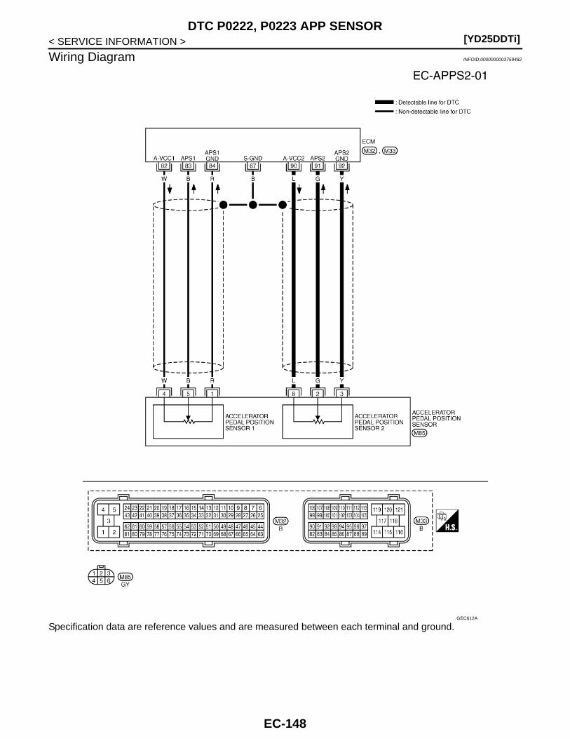
[YD25DDTi]DTC P0222, P0223 APP SENSOR
< SERVICE INFORMATION >
Wiring Diagram INFOID:0000000003759482
Specification data are reference values and are measured between each terminal and ground.GEC612A
EC-148
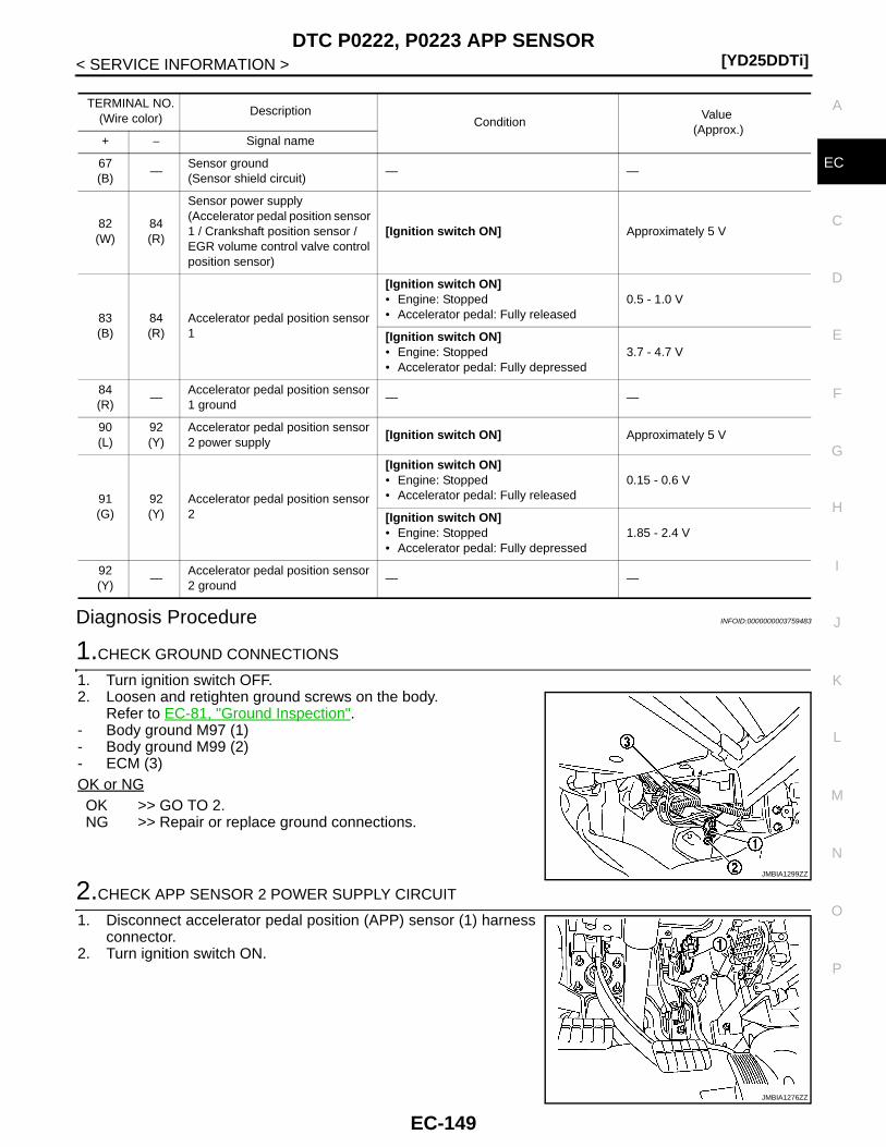
DTC P0222, P0223 APP SENSOR[YD25DDTi]
C
D
E
F
G
H
I
J
K
L
M
A
C
N
P
O
< SERVICE INFORMATION >
E
Diagnosis Procedure INFOID:0000000003759483
1.CHECK GROUND CONNECTIONS
1. Turn ignition switch OFF.2. Loosen and retighten ground screws on the body.
Refer to EC-81, "Ground Inspection".- Body ground M97 (1)- Body ground M99 (2)- ECM (3)OK or NGOK >> GO TO 2.NG >> Repair or replace ground connections.
2.CHECK APP SENSOR 2 POWER SUPPLY CIRCUIT
1. Disconnect accelerator pedal position (APP) sensor (1) harnessconnector.
2. Turn ignition switch ON.
TERMINAL NO.(Wire color)
DescriptionCondition
Value (Approx.)
+ − Signal name
67(B)
—Sensor ground(Sensor shield circuit)
— —
82(W)
84(R)
Sensor power supply(Accelerator pedal position sensor 1 / Crankshaft position sensor / EGR volume control valve control position sensor)
[Ignition switch ON] Approximately 5 V
83(B)
84(R)
Accelerator pedal position sensor 1
[Ignition switch ON]• Engine: Stopped• Accelerator pedal: Fully released
0.5 - 1.0 V
[Ignition switch ON]• Engine: Stopped• Accelerator pedal: Fully depressed
3.7 - 4.7 V
84(R)
—Accelerator pedal position sensor 1 ground
— —
90(L)
92(Y)
Accelerator pedal position sensor 2 power supply
[Ignition switch ON] Approximately 5 V
91(G)
92(Y)
Accelerator pedal position sensor 2
[Ignition switch ON]• Engine: Stopped• Accelerator pedal: Fully released
0.15 - 0.6 V
[Ignition switch ON]• Engine: Stopped• Accelerator pedal: Fully depressed
1.85 - 2.4 V
92(Y)
—Accelerator pedal position sensor 2 ground
— —
JMBIA1299ZZ
JMBIA1276ZZ
EC-149
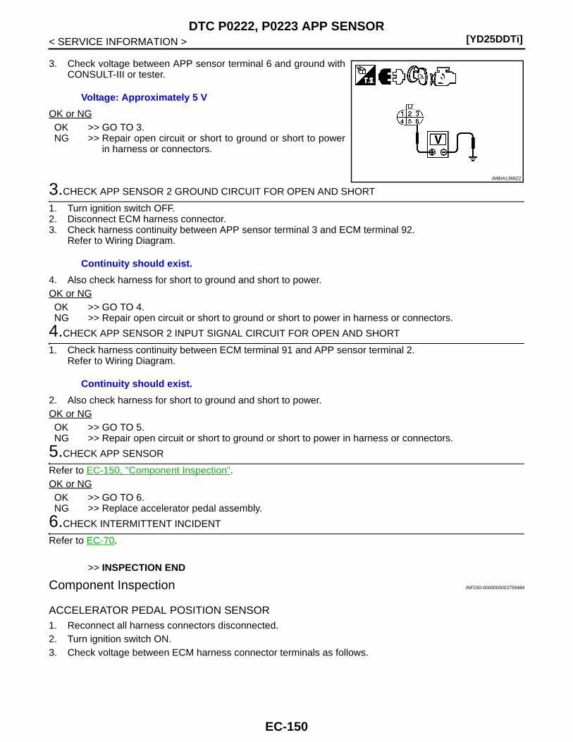
[YD25DDTi]DTC P0222, P0223 APP SENSOR
< SERVICE INFORMATION >
3. Check voltage between APP sensor terminal 6 and ground withCONSULT-III or tester.
OK or NGOK >> GO TO 3.NG >> Repair open circuit or short to ground or short to power
in harness or connectors.
3.CHECK APP SENSOR 2 GROUND CIRCUIT FOR OPEN AND SHORT
1. Turn ignition switch OFF.2. Disconnect ECM harness connector.3. Check harness continuity between APP sensor terminal 3 and ECM terminal 92.
Refer to Wiring Diagram.
4. Also check harness for short to ground and short to power.OK or NGOK >> GO TO 4.NG >> Repair open circuit or short to ground or short to power in harness or connectors.
4.CHECK APP SENSOR 2 INPUT SIGNAL CIRCUIT FOR OPEN AND SHORT
1. Check harness continuity between ECM terminal 91 and APP sensor terminal 2.Refer to Wiring Diagram.
2. Also check harness for short to ground and short to power.OK or NGOK >> GO TO 5.NG >> Repair open circuit or short to ground or short to power in harness or connectors.
5.CHECK APP SENSOR
Refer to EC-150, "Component Inspection".OK or NGOK >> GO TO 6.NG >> Replace accelerator pedal assembly.
6.CHECK INTERMITTENT INCIDENT
Refer to EC-70.
>> INSPECTION END
Component Inspection INFOID:0000000003759484
ACCELERATOR PEDAL POSITION SENSOR1. Reconnect all harness connectors disconnected.2. Turn ignition switch ON.3. Check voltage between ECM harness connector terminals as follows.
Voltage: Approximately 5 V
JMBIA1368ZZ
Continuity should exist.
Continuity should exist.
EC-150
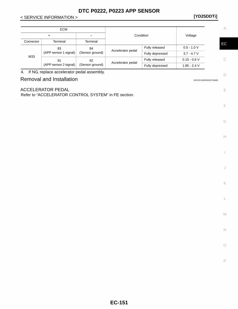
DTC P0222, P0223 APP SENSOR[YD25DDTi]
C
D
E
F
G
H
I
J
K
L
M
A
C
N
P
O
< SERVICE INFORMATION >
E
4. If NG, replace accelerator pedal assembly.
Removal and Installation INFOID:0000000003759485
ACCELERATOR PEDALRefer to “ACCELERATOR CONTROL SYSTEM” in FE section.
ECM
Condition Voltage+ –
Connector Terminal Terminal
M33
83(APP sensor 1 signal)
84(Sensor ground)
Accelerator pedalFully released 0.5 - 1.0 V
Fully depressed 3.7 - 4.7 V
91(APP sensor 2 signal)
92(Sensor ground)
Accelerator pedalFully released 0.15 - 0.6 V
Fully depressed 1.85 - 2.4 V
EC-151
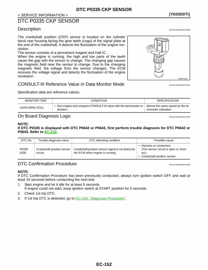
[YD25DDTi]DTC P0335 CKP SENSOR
< SERVICE INFORMATION >
DTC P0335 CKP SENSOR
Description INFOID:0000000003759500
The crankshaft position (CKP) sensor is located on the cylinderblock rear housing facing the gear teeth (cogs) of the signal plate atthe end of the crankshaft. It detects the fluctuation of the engine rev-olution.The sensor consists of a permanent magnet and Hall IC.When the engine is running, the high and low parts of the teethcause the gap with the sensor to change. The changing gap causesthe magnetic field near the sensor to change. Due to the changingmagnetic field, the voltage from the sensor changes. The ECMreceives the voltage signal and detects the fluctuation of the enginerevolution.
CONSULT-III Reference Value in Data Monitor Mode INFOID:0000000003759501
Specification data are reference values.
On Board Diagnosis Logic INFOID:0000000003759502
NOTE:If DTC P0335 is displayed with DTC P0642 or P0643, first perform trouble diagnosis for DTC P0642 orP0643. Refer to EC-210.
DTC Confirmation Procedure INFOID:0000000003759503
NOTE:If DTC Confirmation Procedure has been previously conducted, always turn ignition switch OFF and wait atleast 10 seconds before conducting the next test. 1. Start engine and let it idle for at least 5 seconds.
If engine could not start, keep ignition switch at START position for 5 seconds.2. Check 1st trip DTC.3. If 1st trip DTC is detected, go to EC-154, "Diagnosis Procedure".
MBIB1323E
MONITOR ITEM CONDITION SPECIFICATION
CKPS-RPM (TDC)• Run engine and compare CONSULT-III value with the tachometer in-
dication.Almost the same speed as the ta-chometer indication
DTC No. Trouble diagnosis name DTC detecting condition Possible cause
P03350335
Crankshaft position sensor circuit
Crankshaft position sensor signal is not detect by the ECM when engine is running.
• Harness or connectors(The sensor circuit is open or short-ed.)
• Crankshaft position sensor
EC-152
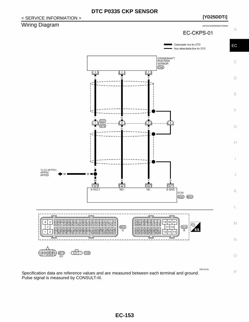
DTC P0335 CKP SENSOR[YD25DDTi]
C
D
E
F
G
H
I
J
K
L
M
A
C
N
P
O
< SERVICE INFORMATION >
E
Wiring Diagram INFOID:0000000003759504
Specification data are reference values and are measured between each terminal and ground.Pulse signal is measured by CONSULT-III.
GEC613A
EC-153
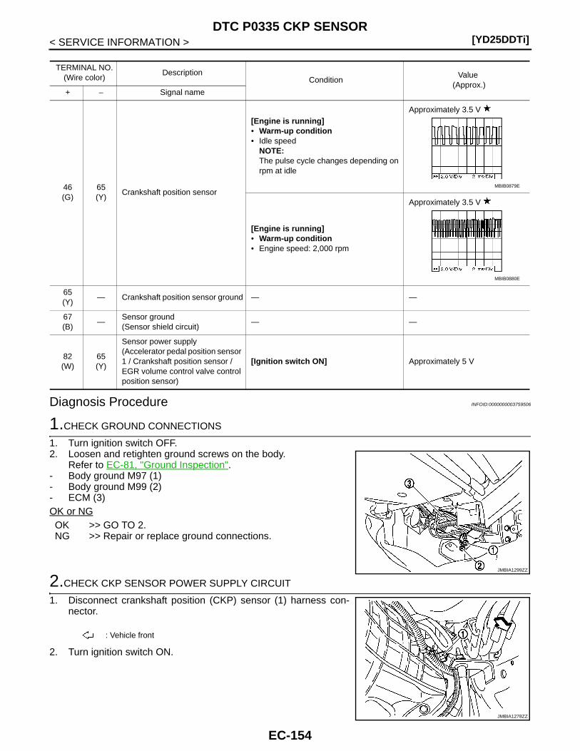
[YD25DDTi]DTC P0335 CKP SENSOR
< SERVICE INFORMATION >
Diagnosis Procedure INFOID:0000000003759506
1.CHECK GROUND CONNECTIONS
1. Turn ignition switch OFF.2. Loosen and retighten ground screws on the body.
Refer to EC-81, "Ground Inspection".- Body ground M97 (1)- Body ground M99 (2)- ECM (3)OK or NGOK >> GO TO 2.NG >> Repair or replace ground connections.
2.CHECK CKP SENSOR POWER SUPPLY CIRCUIT
1. Disconnect crankshaft position (CKP) sensor (1) harness con-nector.
2. Turn ignition switch ON.
TERMINAL NO.(Wire color)
DescriptionCondition
Value (Approx.)
+ − Signal name
46(G)
65(Y)
Crankshaft position sensor
[Engine is running]• Warm-up condition• Idle speed
NOTE:The pulse cycle changes depending on rpm at idle
Approximately 3.5 V
[Engine is running]• Warm-up condition• Engine speed: 2,000 rpm
Approximately 3.5 V
65(Y)
— Crankshaft position sensor ground — —
67(B)
—Sensor ground(Sensor shield circuit)
— —
82(W)
65(Y)
Sensor power supply(Accelerator pedal position sensor 1 / Crankshaft position sensor / EGR volume control valve control position sensor)
[Ignition switch ON] Approximately 5 V
MBIB0879E
MBIB0880E
JMBIA1299ZZ
: Vehicle front
JMBIA1278ZZ
EC-154
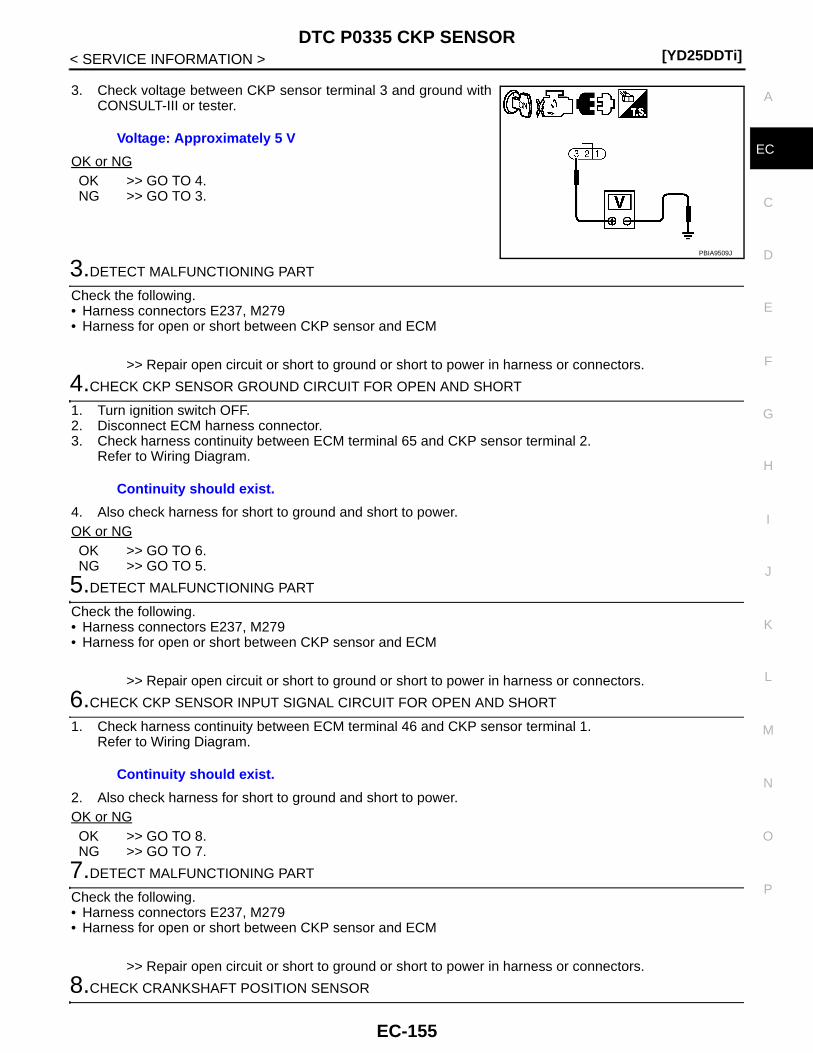
DTC P0335 CKP SENSOR[YD25DDTi]
C
D
E
F
G
H
I
J
K
L
M
A
C
N
P
O
< SERVICE INFORMATION >
E
3. Check voltage between CKP sensor terminal 3 and ground withCONSULT-III or tester.
OK or NGOK >> GO TO 4.NG >> GO TO 3.
3.DETECT MALFUNCTIONING PART
Check the following.• Harness connectors E237, M279• Harness for open or short between CKP sensor and ECM
>> Repair open circuit or short to ground or short to power in harness or connectors.
4.CHECK CKP SENSOR GROUND CIRCUIT FOR OPEN AND SHORT
1. Turn ignition switch OFF.2. Disconnect ECM harness connector.3. Check harness continuity between ECM terminal 65 and CKP sensor terminal 2.
Refer to Wiring Diagram.
4. Also check harness for short to ground and short to power.OK or NGOK >> GO TO 6.NG >> GO TO 5.
5.DETECT MALFUNCTIONING PART
Check the following.• Harness connectors E237, M279• Harness for open or short between CKP sensor and ECM
>> Repair open circuit or short to ground or short to power in harness or connectors.
6.CHECK CKP SENSOR INPUT SIGNAL CIRCUIT FOR OPEN AND SHORT
1. Check harness continuity between ECM terminal 46 and CKP sensor terminal 1.Refer to Wiring Diagram.
2. Also check harness for short to ground and short to power.OK or NGOK >> GO TO 8.NG >> GO TO 7.
7.DETECT MALFUNCTIONING PART
Check the following.• Harness connectors E237, M279• Harness for open or short between CKP sensor and ECM
>> Repair open circuit or short to ground or short to power in harness or connectors.
8.CHECK CRANKSHAFT POSITION SENSOR
Voltage: Approximately 5 V
PBIA9509J
Continuity should exist.
Continuity should exist.
EC-155
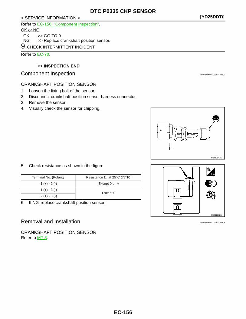
[YD25DDTi]DTC P0335 CKP SENSOR
< SERVICE INFORMATION >Refer to EC-156, "Component Inspection".OK or NGOK >> GO TO 9.NG >> Replace crankshaft position sensor.
9.CHECK INTERMITTENT INCIDENT
Refer to EC-70.
>> INSPECTION END
Component Inspection INFOID:0000000003759507
CRANKSHAFT POSITION SENSOR 1. Loosen the fixing bolt of the sensor.2. Disconnect crankshaft position sensor harness connector.3. Remove the sensor.4. Visually check the sensor for chipping.
5. Check resistance as shown in the figure.
6. If NG, replace crankshaft position sensor.
Removal and Installation INFOID:0000000003759508
CRANKSHAFT POSITION SENSORRefer to MT-3.
MBIB0647E
Terminal No. (Polarity) Resistance Ω [at 25°C (77°F)]
1 (+) - 2 (-) Except 0 or ∞
1 (+) - 3 (-)Except 0
2 (+) - 3 (-)
MBIB1662E
EC-156

DTC P0336 CKP SENSOR[YD25DDTi]
C
D
E
F
G
H
I
J
K
L
M
A
C
N
P
O
< SERVICE INFORMATION >
E
DTC P0336 CKP SENSOR
Description INFOID:0000000003759509
The crankshaft position (CKP) sensor is located on the cylinderblock rear housing facing the gear teeth (cogs) of the signal plate atthe end of the crankshaft. It detects the fluctuation of the engine rev-olution.The sensor consists of a permanent magnet and Hall IC.When the engine is running, the high and low parts of the teethcause the gap with the sensor to change. The changing gap causesthe magnetic field near the sensor to change. Due to the changingmagnetic field, the voltage from the sensor changes. The ECMreceives the voltage signal and detects the fluctuation of the enginerevolution.
CONSULT-III Reference Value in Data Monitor Mode INFOID:0000000003759510
Specification data are reference values.
On Board Diagnosis Logic INFOID:0000000003759511
NOTE:If DTC P0336 is displayed with DTC P0642 or P0643, first perform trouble diagnosis for DTC P0642 orP0643. Refer to EC-210.
DTC Confirmation Procedure INFOID:0000000003759512
NOTE:If DTC Confirmation Procedure has been previously conducted, always turn ignition switch OFF and wait atleast 10 seconds before conducting the next test. 1. Start engine and let it idle for at least 5 seconds.
If engine could not start, keep ignition switch at START position for 5 seconds.2. Check 1st trip DTC.3. If 1st trip DTC is detected, go to EC-159, "Diagnosis Procedure".
MBIB1323E
MONITOR ITEM CONDITION SPECIFICATION
CKPS·RPM (TDC)• Tachometer: Connect• Run engine and compare CONSULT-III value with the tachometer indi-
cation.
Almost the same speed as the ta-chometer indication.
DTC No. Trouble diagnosis name DTC detecting condition Possible cause
P03360336
Crankshaft position sensor circuit range/performance
Crankshaft position sensor signal is not in the normal pattern when engine is running.
• Harness or connectors(The sensor circuit is open or short-ed.)
• Crankshaft position sensor• Signal plate
EC-157
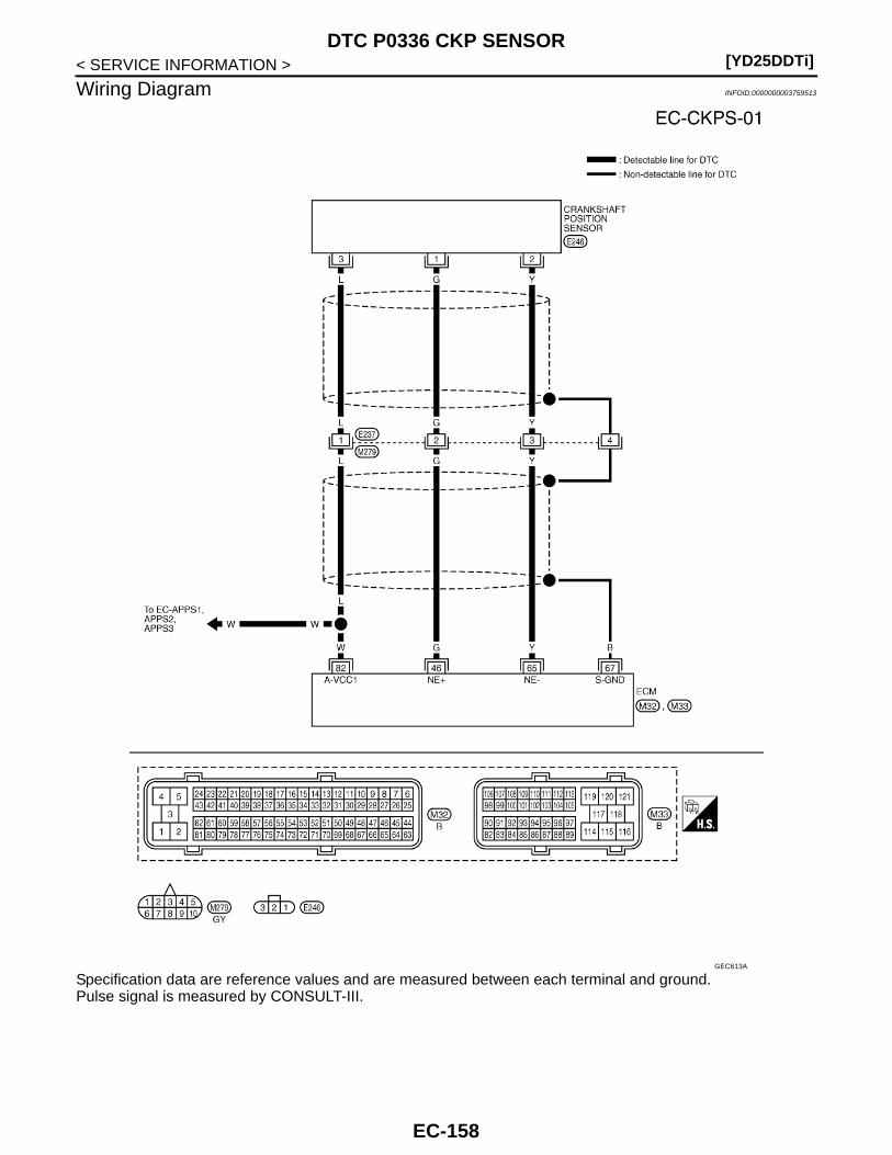
[YD25DDTi]DTC P0336 CKP SENSOR
< SERVICE INFORMATION >
Wiring Diagram INFOID:0000000003759513
Specification data are reference values and are measured between each terminal and ground.Pulse signal is measured by CONSULT-III.
GEC613A
EC-158
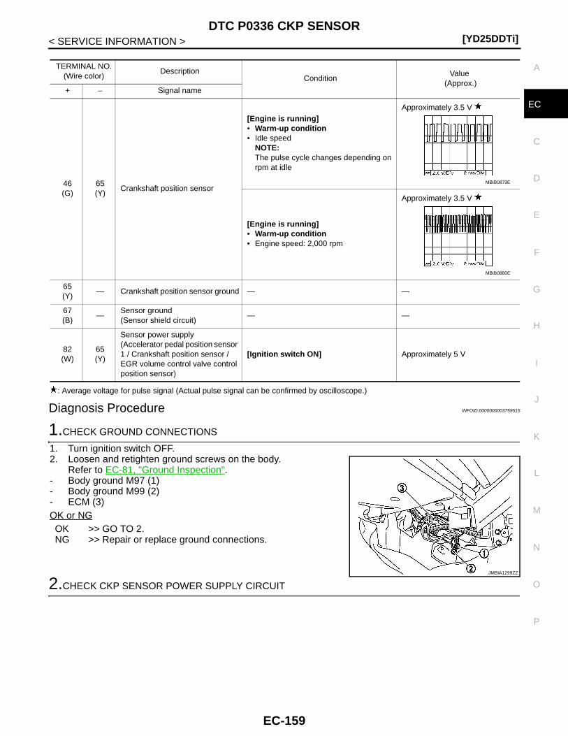
DTC P0336 CKP SENSOR[YD25DDTi]
C
D
E
F
G
H
I
J
K
L
M
A
C
N
P
O
< SERVICE INFORMATION >
E
: Average voltage for pulse signal (Actual pulse signal can be confirmed by oscilloscope.)
Diagnosis Procedure INFOID:0000000003759515
1.CHECK GROUND CONNECTIONS
1. Turn ignition switch OFF.2. Loosen and retighten ground screws on the body.
Refer to EC-81, "Ground Inspection".- Body ground M97 (1)- Body ground M99 (2)- ECM (3)OK or NGOK >> GO TO 2.NG >> Repair or replace ground connections.
2.CHECK CKP SENSOR POWER SUPPLY CIRCUIT
TERMINAL NO.(Wire color)
DescriptionCondition
Value (Approx.)
+ − Signal name
46(G)
65(Y)
Crankshaft position sensor
[Engine is running]• Warm-up condition• Idle speed
NOTE:The pulse cycle changes depending on rpm at idle
Approximately 3.5 V
[Engine is running]• Warm-up condition• Engine speed: 2,000 rpm
Approximately 3.5 V
65(Y)
— Crankshaft position sensor ground — —
67(B)
—Sensor ground(Sensor shield circuit)
— —
82(W)
65(Y)
Sensor power supply(Accelerator pedal position sensor 1 / Crankshaft position sensor / EGR volume control valve control position sensor)
[Ignition switch ON] Approximately 5 V
MBIB0879E
MBIB0880E
JMBIA1299ZZ
EC-159
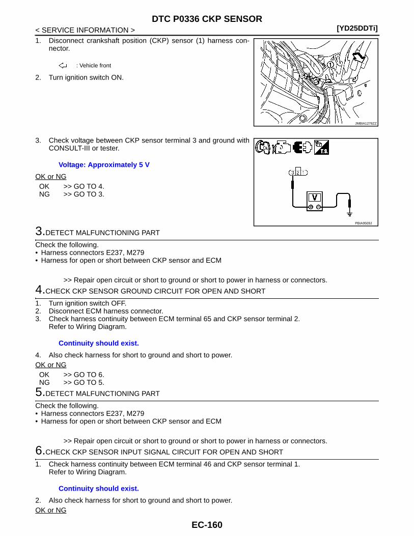
[YD25DDTi]DTC P0336 CKP SENSOR
< SERVICE INFORMATION >1. Disconnect crankshaft position (CKP) sensor (1) harness con-
nector.
2. Turn ignition switch ON.
3. Check voltage between CKP sensor terminal 3 and ground withCONSULT-III or tester.
OK or NGOK >> GO TO 4.NG >> GO TO 3.
3.DETECT MALFUNCTIONING PART
Check the following.• Harness connectors E237, M279• Harness for open or short between CKP sensor and ECM
>> Repair open circuit or short to ground or short to power in harness or connectors.
4.CHECK CKP SENSOR GROUND CIRCUIT FOR OPEN AND SHORT
1. Turn ignition switch OFF.2. Disconnect ECM harness connector.3. Check harness continuity between ECM terminal 65 and CKP sensor terminal 2.
Refer to Wiring Diagram.
4. Also check harness for short to ground and short to power.OK or NGOK >> GO TO 6.NG >> GO TO 5.
5.DETECT MALFUNCTIONING PART
Check the following.• Harness connectors E237, M279• Harness for open or short between CKP sensor and ECM
>> Repair open circuit or short to ground or short to power in harness or connectors.
6.CHECK CKP SENSOR INPUT SIGNAL CIRCUIT FOR OPEN AND SHORT
1. Check harness continuity between ECM terminal 46 and CKP sensor terminal 1.Refer to Wiring Diagram.
2. Also check harness for short to ground and short to power.OK or NG
: Vehicle front
JMBIA1278ZZ
Voltage: Approximately 5 V
PBIA9509J
Continuity should exist.
Continuity should exist.
EC-160
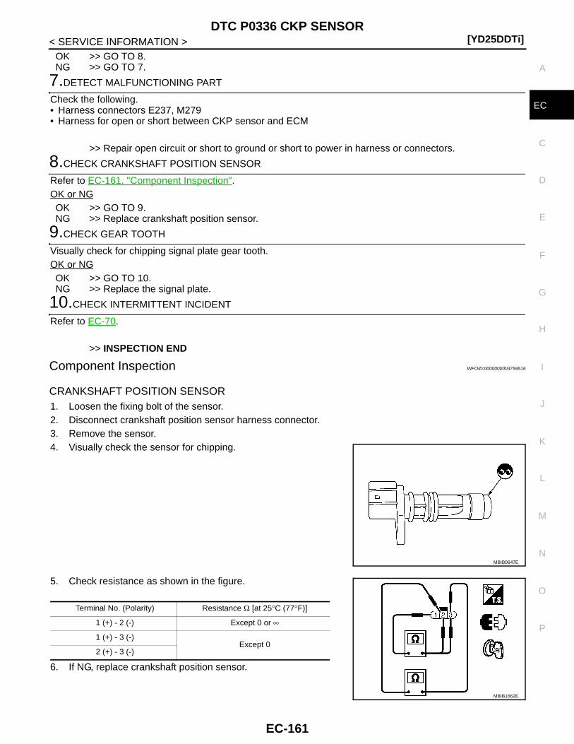
DTC P0336 CKP SENSOR[YD25DDTi]
C
D
E
F
G
H
I
J
K
L
M
A
C
N
P
O
< SERVICE INFORMATION >
E
OK >> GO TO 8.NG >> GO TO 7.
7.DETECT MALFUNCTIONING PART
Check the following.• Harness connectors E237, M279• Harness for open or short between CKP sensor and ECM
>> Repair open circuit or short to ground or short to power in harness or connectors.
8.CHECK CRANKSHAFT POSITION SENSOR
Refer to EC-161, "Component Inspection".OK or NGOK >> GO TO 9.NG >> Replace crankshaft position sensor.
9.CHECK GEAR TOOTH
Visually check for chipping signal plate gear tooth.OK or NGOK >> GO TO 10.NG >> Replace the signal plate.
10.CHECK INTERMITTENT INCIDENT
Refer to EC-70.
>> INSPECTION END
Component Inspection INFOID:0000000003759516
CRANKSHAFT POSITION SENSOR1. Loosen the fixing bolt of the sensor.2. Disconnect crankshaft position sensor harness connector.3. Remove the sensor.4. Visually check the sensor for chipping.
5. Check resistance as shown in the figure.
6. If NG, replace crankshaft position sensor.
MBIB0647E
Terminal No. (Polarity) Resistance Ω [at 25°C (77°F)]
1 (+) - 2 (-) Except 0 or ∞
1 (+) - 3 (-)Except 0
2 (+) - 3 (-)
MBIB1662E
EC-161
[YD25DDTi]DTC P0336 CKP SENSOR
< SERVICE INFORMATION >
Removal and Installation INFOID:0000000003759517
CRANKSHAFT POSITION SENSORRefer to MT-3.
EC-162

DTC P0340 CMP SENSOR[YD25DDTi]
C
D
E
F
G
H
I
J
K
L
M
A
C
N
P
O
< SERVICE INFORMATION >
E
DTC P0340 CMP SENSOR
Description INFOID:0000000003759518
The camshaft position (CMP) sensor senses the retraction with cam-shaft (left side) to identify a particular cylinder. The camshaft position(CMP) sensor senses the piston position.When the crankshaft position (CKP) sensor system becomes inoper-ative, the camshaft position (CMP) sensor provides various controlsof engine parts instead, utilizing timing of cylinder identification sig-nals.The sensor consists of a permanent magnet and Hall IC.When engine is running, the high and low parts of the teeth causethe gap with the sensor to change.The changing gap causes the magnetic field near the sensor tochange.Due to the changing magnetic field, the voltage from the sensor changes.
On Board Diagnosis Logic INFOID:0000000003759519
NOTE:If DTC P0340 is displayed with DTC P0652 or P0653, first perform trouble diagnosis for DTC P0652 orP0653. Refer to EC-214.
DTC Confirmation Procedure INFOID:0000000003759520
NOTE:If DTC Confirmation Procedure has been previously conducted, always turn ignition switch OFF and wait atleast 10 seconds before conducting the next test. 1. Start engine and let it idle for at least 5 seconds.
If engine could not start, keep ignition switch at START position for 5 seconds.2. Check 1st trip DTC.3. If 1st trip DTC is detected, go to EC-165, "Diagnosis Procedure".
MBIB1323E
DTC No. Trouble diagnosis name DTC detecting condition Possible cause
P03400340
Camshaft position sensor circuit
Camshaft position sensor signal is not detect by the ECM when engine is running.
• Harness or connectors(The sensor circuit is open or short-ed.)
• Camshaft position sensor
EC-163
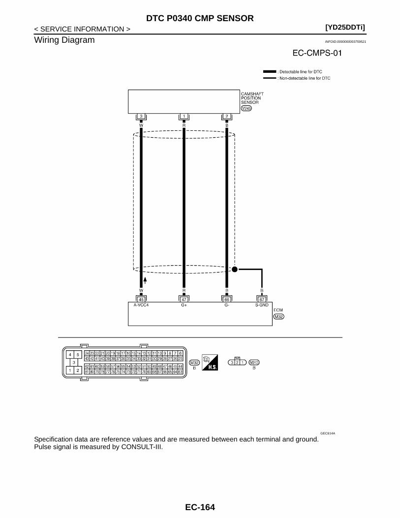
[YD25DDTi]DTC P0340 CMP SENSOR
< SERVICE INFORMATION >
Wiring Diagram INFOID:0000000003759521
Specification data are reference values and are measured between each terminal and ground.Pulse signal is measured by CONSULT-III.
GEC614A
EC-164

DTC P0340 CMP SENSOR[YD25DDTi]
C
D
E
F
G
H
I
J
K
L
M
A
C
N
P
O
< SERVICE INFORMATION >
E
: Average voltage for pulse signal (Actual pulse signal can be confirmed by oscilloscope.)
Diagnosis Procedure INFOID:0000000003759523
1.CHECK GROUND CONNECTIONS
1. Turn ignition switch OFF.2. Loosen and retighten ground screws on the body.
Refer to EC-81, "Ground Inspection".- Body ground M97 (1)- Body ground M99 (2)- ECM (3)OK or NGOK >> GO TO 2.NG >> Repair or replace ground connections.
2.CHECK CMP SENSOR POWER SUPPLY CIRCUIT
1. Disconnect camshaft position (CMP) sensor (1) harness con-nector.
2. Turn ignition switch ON.
TERMINAL NO.(Wire color)
DescriptionCondition
Value (Approx.)
+ − Signal name
45(W)
66(B)
Camshaft position sensor power supply
[Ignition switch ON] Approximately 5 V
47(R)
66(B)
Camshaft position sensor
[Engine is running]• Warm-up condition• Idle speed
NOTE:The pulse cycle changes depending on rpm at idle
Approximately 4.7 V
[Engine is running]• Warm-up condition• Engine speed: 2,000 rpm
Approximately 4.7 V
66(B)
— Camshaft position sensor ground — —
67(B)
—Sensor ground(Sensor shield circuit)
— —
MBIB0877E
MBIB0878E
JMBIA1299ZZ
: Vehicle front
JMBIA1273ZZ
EC-165

[YD25DDTi]DTC P0340 CMP SENSOR
< SERVICE INFORMATION >3. Check voltage between CMP sensor terminal 3 and ground with
CONSULT-III or tester.
OK or NGOK >> GO TO 3.NG >> Repair open circuit or short to ground or short to power
in harness or connectors.
3.CHECK CMP SENSOR GROUND CIRCUIT FOR OPEN AND SHORT
1. Turn ignition switch OFF.2. Disconnect ECM harness connector.3. Check harness continuity between ECM terminal 66 and CMP sensor terminal 2.
4. Also check harness for short to ground and short to power.OK or NGOK >> GO TO 4.NG >> Repair open circuit or short to ground or short to power in harness or connectors.
4.CHECK CMP SENSOR INPUT SIGNAL CIRCUIT FOR OPEN AND SHORT
1. Check harness continuity between ECM terminal 47 and CMP sensor terminal 1. Refer to Wiring Diagram.
2. Also check harness for short to ground and short to power.OK or NGOK >> GO TO 5.NG >> Repair open circuit or short to ground or short to power in harness or connectors.
5.CHECK CAMSHAFT POSITION SENSOR
Refer to EC-166, "Component Inspection".OK or NGOK >> GO TO 6.NG >> Replace camshaft position sensor.
6.CHECK INTERMITTENT INCIDENT
Refer to EC-70.
>> INSPECTION END
Component Inspection INFOID:0000000003759524
CAMSHAFT POSITION SENSOR 1. Loosen the fixing bolt of the sensor.2. Disconnect camshaft position sensor harness connector.3. Remove the sensor.
Voltage: Approximately 5 V
MBIB1736E
Continuity should exist.
Continuity should exist.
EC-166
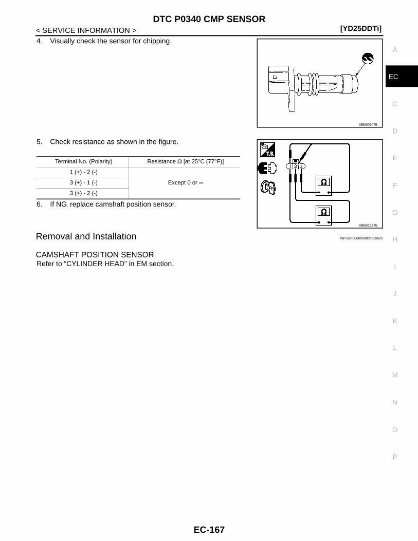
DTC P0340 CMP SENSOR[YD25DDTi]
C
D
E
F
G
H
I
J
K
L
M
A
C
N
P
O
< SERVICE INFORMATION >
E
4. Visually check the sensor for chipping.
5. Check resistance as shown in the figure.
6. If NG, replace camshaft position sensor.
Removal and Installation INFOID:0000000003759525
CAMSHAFT POSITION SENSOR Refer to “CYLINDER HEAD” in EM section.
MBIB0647E
Terminal No. (Polarity) Resistance Ω [at 25°C (77°F)]
1 (+) - 2 (-)
Except 0 or ∞3 (+) - 1 (-)
3 (+) - 2 (-)
MBIB1737E
EC-167

[YD25DDTi]DTC P0341 CMP SENSOR
< SERVICE INFORMATION >
DTC P0341 CMP SENSOR
Description INFOID:0000000003759526
The camshaft position (CMP) sensor senses the retraction with cam-shaft (left side) to identify a particular cylinder. The camshaft position(CMP) sensor senses the piston position.When the crankshaft position (CKP) sensor system becomes inoper-ative, the camshaft position (CMP) sensor provides various controlsof engine parts instead, utilizing timing of cylinder identification sig-nals.The sensor consists of a permanent magnet and Hall IC.When engine is running, the high and low parts of the teeth causethe gap with the sensor to change.The changing gap causes the magnetic field near the sensor tochange.Due to the changing magnetic field, the voltage from the sensor changes.
On Board Diagnosis Logic INFOID:0000000003759527
NOTE:If DTC P0341 is displayed with DTC P0652 or P0653, first perform trouble diagnosis for DTC P0652 orP0653. Refer to EC-214.
DTC Confirmation Procedure INFOID:0000000003759528
NOTE:If DTC Confirmation Procedure has been previously conducted, always turn ignition switch OFF and wait atleast 10 seconds before conducting the next test. 1. Start engine and let it idle for at least 5 seconds.
If engine could not start, keep ignition switch at START position for 5 seconds.2. Check 1st trip DTC.3. If 1st trip DTC is detected, go to EC-170, "Diagnosis Procedure".
MBIB1323E
DTC No. Trouble diagnosis name DTC detecting condition Possible cause
P03410341
Camshaft position sensor circuit range/performance
Camshaft position sensor signal is not in the nor-mal pattern when engine is running.
• Harness connectors(The sensor circuit is opener shorted.)
• Camshaft position sensor• Starter motor• Starting system circuit• Signal plate
EC-168
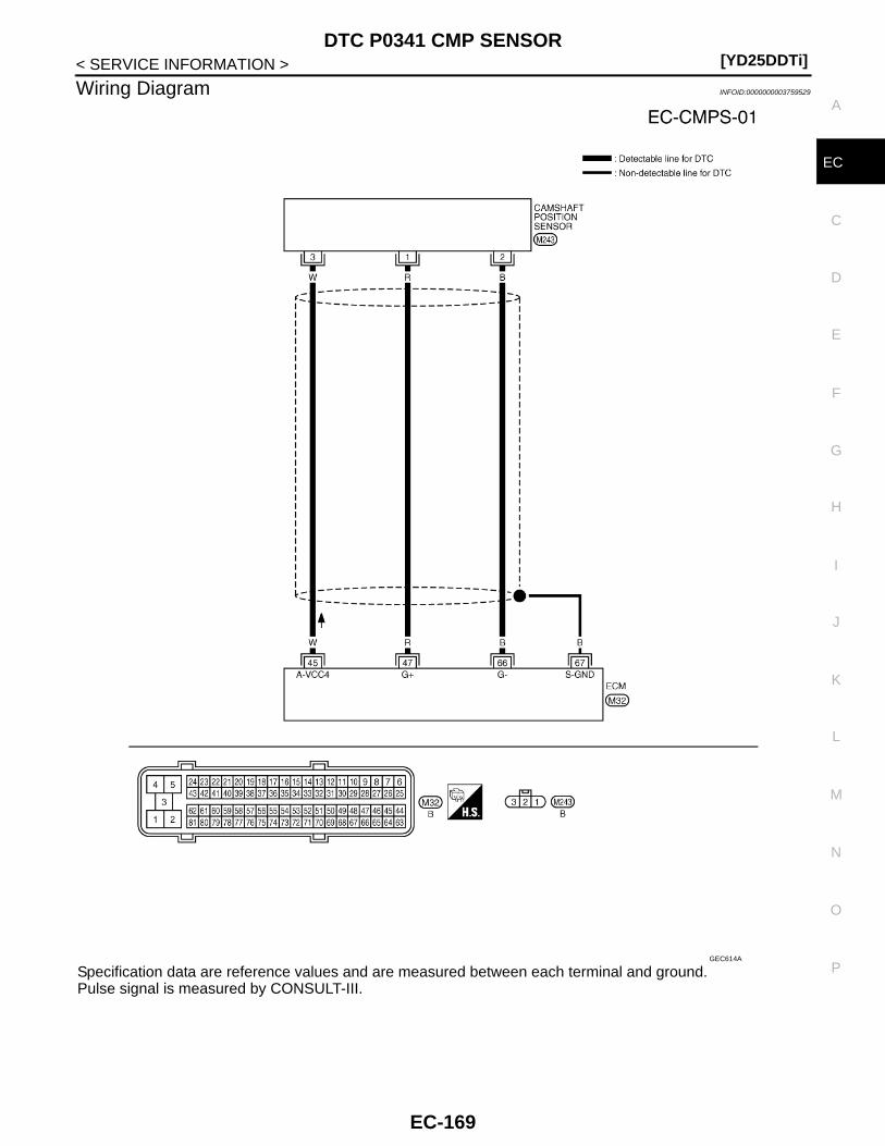
DTC P0341 CMP SENSOR[YD25DDTi]
C
D
E
F
G
H
I
J
K
L
M
A
C
N
P
O
< SERVICE INFORMATION >
E
Wiring Diagram INFOID:0000000003759529
Specification data are reference values and are measured between each terminal and ground.Pulse signal is measured by CONSULT-III.
GEC614A
EC-169

[YD25DDTi]DTC P0341 CMP SENSOR
< SERVICE INFORMATION >
: Average voltage for pulse signal (Actual pulse signal can be confirmed by oscilloscope.)
Diagnosis Procedure INFOID:0000000003759531
1.CHECK STARTING SYSTEM
Turn ignition switch to START position.
Yes or NoYes >> GO TO 2.No >> Check starting system. (Refer to “STARTING SYSTEM in EL section.)
2.CHECK GROUND CONNECTIONS
1. Turn ignition switch OFF.2. Loosen and retighten ground screws on the body.
Refer to EC-81, "Ground Inspection".- Body ground M97 (1)- Body ground M99 (2)- ECM (3)OK or NGOK >> GO TO 3.NG >> Repair or replace ground connections.
3.CHECK CMP SENSOR POWER SUPPLY CIRCUIT
TERMINAL NO.(Wire color)
DescriptionCondition
Value (Approx.)
+ − Signal name
45(W)
66(B)
Camshaft position sensor power supply
[Ignition switch ON] Approximately 5 V
47(R)
66(B)
Camshaft position sensor
[Engine is running]• Warm-up condition• Idle speed
NOTE:The pulse cycle changes depending on rpm at idle
Approximately 4.7 V
[Engine is running]• Warm-up condition• Engine speed: 2,000 rpm
Approximately 4.7 V
66(B)
— Camshaft position sensor ground — —
67(B)
—Sensor ground(Sensor shield circuit)
— —
MBIB0877E
MBIB0878E
Does the engine turn over?Does the starter motor operate?
JMBIA1299ZZ
EC-170
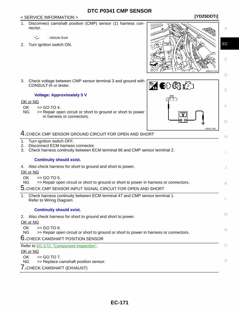
DTC P0341 CMP SENSOR[YD25DDTi]
C
D
E
F
G
H
I
J
K
L
M
A
C
N
P
O
< SERVICE INFORMATION >
E
1. Disconnect camshaft position (CMP) sensor (1) harness con-nector.
2. Turn ignition switch ON.
3. Check voltage between CMP sensor terminal 3 and ground withCONSULT-III or tester.
OK or NGOK >> GO TO 4.NG >> Repair open circuit or short to ground or short to power
in harness or connectors.
4.CHECK CMP SENSOR GROUND CIRCUIT FOR OPEN AND SHORT
1. Turn ignition switch OFF.2. Disconnect ECM harness connector.3. Check harness continuity between ECM terminal 66 and CMP sensor terminal 2.
4. Also check harness for short to ground and short to power.OK or NGOK >> GO TO 5.NG >> Repair open circuit or short to ground or short to power in harness or connectors.
5.CHECK CMP SENSOR INPUT SIGNAL CIRCUIT FOR OPEN AND SHORT
1. Check harness continuity between ECM terminal 47 and CMP sensor terminal 1. Refer to Wiring Diagram.
2. Also check harness for short to ground and short to power.OK or NGOK >> GO TO 6.NG >> Repair open circuit or short to ground or short to power in harness or connectors.
6.CHECK CAMSHAFT POSITION SENSOR
Refer to EC-172, "Component Inspection".OK or NGOK >> GO TO 7.NG >> Replace camshaft position sensor.
7.CHECK CAMSHAFT (EXHAUST)
: Vehicle front
JMBIA1273ZZ
Voltage: Approximately 5 V
MBIB1736E
Continuity should exist.
Continuity should exist.
EC-171
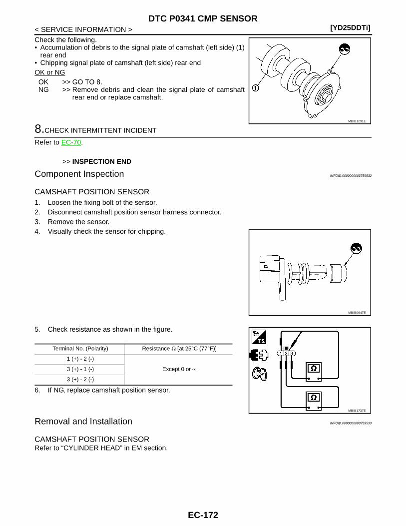
[YD25DDTi]DTC P0341 CMP SENSOR
< SERVICE INFORMATION >Check the following.• Accumulation of debris to the signal plate of camshaft (left side) (1)
rear end• Chipping signal plate of camshaft (left side) rear endOK or NGOK >> GO TO 8.NG >> Remove debris and clean the signal plate of camshaft
rear end or replace camshaft.
8.CHECK INTERMITTENT INCIDENT
Refer to EC-70.
>> INSPECTION END
Component Inspection INFOID:0000000003759532
CAMSHAFT POSITION SENSOR 1. Loosen the fixing bolt of the sensor.2. Disconnect camshaft position sensor harness connector.3. Remove the sensor.4. Visually check the sensor for chipping.
5. Check resistance as shown in the figure.
6. If NG, replace camshaft position sensor.
Removal and Installation INFOID:0000000003759533
CAMSHAFT POSITION SENSOR Refer to “CYLINDER HEAD” in EM section.
MBIB1291E
MBIB0647E
Terminal No. (Polarity) Resistance Ω [at 25°C (77°F)]
1 (+) - 2 (-)
Except 0 or ∞3 (+) - 1 (-)
3 (+) - 2 (-)
MBIB1737E
EC-172

DTC P0380 GLOW RELAY[YD25DDTi]
C
D
E
F
G
H
I
J
K
L
M
A
C
N
P
O
< SERVICE INFORMATION >
E
DTC P0380 GLOW RELAY
On Board Diagnosis Logic INFOID:0000000003759534
DTC Confirmation Procedure INFOID:0000000003759535
NOTE:If DTC Confirmation Procedure has been previously conducted, always turn ignition switch OFF and wait atleast 10 seconds before conducting the next test. 1. Turn ignition switch ON.2. Wait at least 5 seconds.3. Check 1st trip DTC.4. If 1st trip DTC is detected, go to EC-174, "Diagnosis Procedure".
DTC No. Trouble diagnosis name DTC detecting condition Possible cause
P03800380
Glow relay circuit
An excessively low voltage is sent to ECM through glow relay.
• Harness or connectors(The glow relay circuit is open or shorted.)
• Glow relay
An excessively high voltage is sent to ECM through glow relay.
• Harness or connectors(The glow relay circuit is short-ed.)
• Glow relay
EC-173
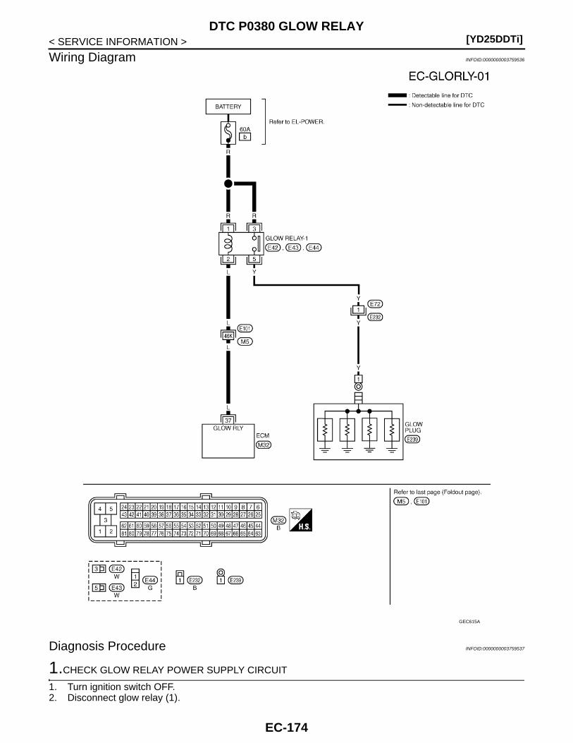
[YD25DDTi]DTC P0380 GLOW RELAY
< SERVICE INFORMATION >
Wiring Diagram INFOID:0000000003759536
Diagnosis Procedure INFOID:0000000003759537
1.CHECK GLOW RELAY POWER SUPPLY CIRCUIT
1. Turn ignition switch OFF.2. Disconnect glow relay (1).
GEC615A
EC-174
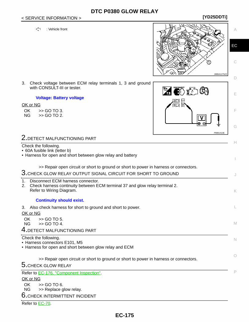
DTC P0380 GLOW RELAY[YD25DDTi]
C
D
E
F
G
H
I
J
K
L
M
A
C
N
P
O
< SERVICE INFORMATION >
E
3. Check voltage between ECM relay terminals 1, 3 and groundwith CONSULT-III or tester.
OK or NGOK >> GO TO 3.NG >> GO TO 2.
2.DETECT MALFUNCTIONING PART
Check the following.• 60A fusible link (letter b)• Harness for open and short between glow relay and battery
>> Repair open circuit or short to ground or short to power in harness or connectors.
3.CHECK GLOW RELAY OUTPUT SIGNAL CIRCUIT FOR SHORT TO GROUND
1. Disconnect ECM harness connector.2. Check harness continuity between ECM terminal 37 and glow relay terminal 2.
Refer to Wiring Diagram.
3. Also check harness for short to ground and short to power.OK or NGOK >> GO TO 5.NG >> GO TO 4.
4.DETECT MALFUNCTIONING PART
Check the following.• Harness connectors E101, M5• Harness for open and short between glow relay and ECM
>> Repair open circuit or short to ground or short to power in harness or connectors.
5.CHECK GLOW RELAY
Refer to EC-176, "Component Inspection".OK or NGOK >> GO TO 6.NG >> Replace glow relay.
6.CHECK INTERMITTENT INCIDENT
Refer to EC-70.
: Vehicle front
JMBIA1275ZZ
Voltage: Battery voltage
PBIB1413E
Continuity should exist.
EC-175

[YD25DDTi]DTC P0380 GLOW RELAY
< SERVICE INFORMATION >
>> INSPECTION END
Component Inspection INFOID:0000000003759538
GLOW RELAYCheck continuity between glow relay terminals 3 and 5 under the fol-lowing conditions.
Operation takes less than 1 second.
Conditions Continuity
12V direct current supply between termi-nals 1 and 2
Yes
No current supply No
PBIB0428E
EC-176

DTC P0403 EGR SYSTEM[YD25DDTi]
C
D
E
F
G
H
I
J
K
L
M
A
C
N
P
O
< SERVICE INFORMATION >
E
DTC P0403 EGR SYSTEM
Description INFOID:0000000003759539
SYSTEM DESCRIPTION
*: This signal is sent to the ECM through CAN communication line.
This system controls the flow rate of EGR led from exhaust manifold to intake manifold. The opening of theEGR passage in the EGR volume control valve changes to control the EGR flow rate. A built-in DC motormoves the valve continuously corresponding to the ECM output signal. The EGR volume control valve controlposition sensor detects the valve position and sends the voltage signals to the ECM. The ECM judges the cur-rent opening angle of the valve from this signals and the ECM controls the DC motor to make the valve open-ing angle properly.The opening of the valve varies for optimum engine control. The optimum value stored in the ECM is deter-mined by considering various engine conditions.The EGR volume control valve remains close under the following conditions.• Engine stopped• Engine starting• Low engine coolant temperature• Excessively high engine coolant temperature• High engine speed• Accelerator pedal fully depressed
COMPONENT DESCRIPTION
EGR Volume Control Valve
Sensor Input Signal to ECM ECM Function Actuator
Crankshaft position sensor Engine speed
EGR volume controlEGR volume control valve
Engine coolant temperature sensor Engine coolant temperature
Mass air flow sensor Amount of intake air
Accelerator pedal position sensor Accelerator pedal position
Vehicle speed sensor Vehicle speed*
Ignition switch Start signal
Air conditioner switch Air conditioner operation*
Intake air temperature sensor Intake air temperature
Barometric pressure sensor Barometric pressure
EGR volume control valve control position sensor
EGR volume control valve control po-sition
JMBIA1369GB
EC-177
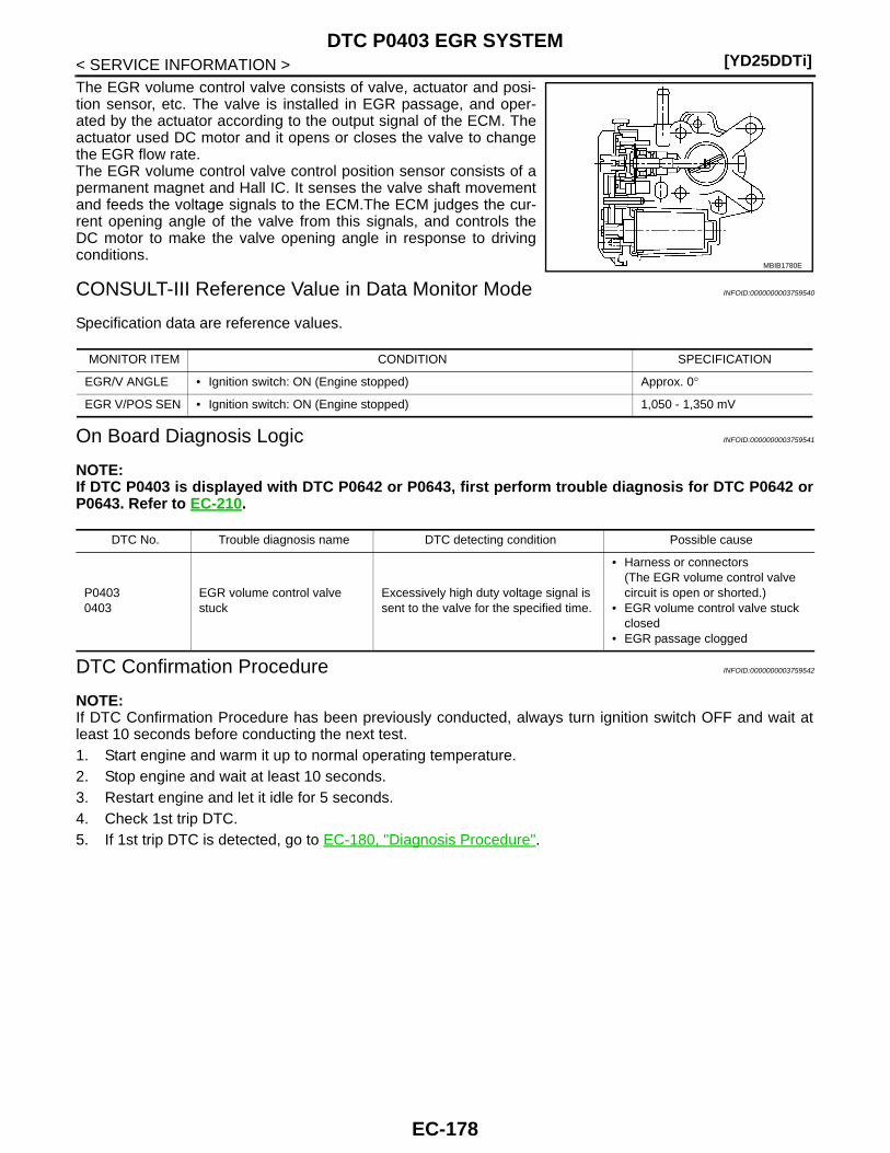
[YD25DDTi]DTC P0403 EGR SYSTEM
< SERVICE INFORMATION >The EGR volume control valve consists of valve, actuator and posi-tion sensor, etc. The valve is installed in EGR passage, and oper-ated by the actuator according to the output signal of the ECM. Theactuator used DC motor and it opens or closes the valve to changethe EGR flow rate.The EGR volume control valve control position sensor consists of apermanent magnet and Hall IC. It senses the valve shaft movementand feeds the voltage signals to the ECM.The ECM judges the cur-rent opening angle of the valve from this signals, and controls theDC motor to make the valve opening angle in response to drivingconditions.
CONSULT-III Reference Value in Data Monitor Mode INFOID:0000000003759540
Specification data are reference values.
On Board Diagnosis Logic INFOID:0000000003759541
NOTE:If DTC P0403 is displayed with DTC P0642 or P0643, first perform trouble diagnosis for DTC P0642 orP0643. Refer to EC-210.
DTC Confirmation Procedure INFOID:0000000003759542
NOTE:If DTC Confirmation Procedure has been previously conducted, always turn ignition switch OFF and wait atleast 10 seconds before conducting the next test.1. Start engine and warm it up to normal operating temperature.2. Stop engine and wait at least 10 seconds.3. Restart engine and let it idle for 5 seconds.4. Check 1st trip DTC.5. If 1st trip DTC is detected, go to EC-180, "Diagnosis Procedure".
MBIB1780E
MONITOR ITEM CONDITION SPECIFICATION
EGR/V ANGLE • Ignition switch: ON (Engine stopped) Approx. 0°
EGR V/POS SEN • Ignition switch: ON (Engine stopped) 1,050 - 1,350 mV
DTC No. Trouble diagnosis name DTC detecting condition Possible cause
P04030403
EGR volume control valve stuck
Excessively high duty voltage signal is sent to the valve for the specified time.
• Harness or connectors(The EGR volume control valve circuit is open or shorted.)
• EGR volume control valve stuck closed
• EGR passage clogged
EC-178
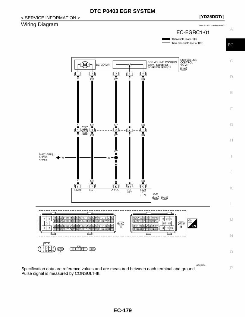
DTC P0403 EGR SYSTEM[YD25DDTi]
C
D
E
F
G
H
I
J
K
L
M
A
C
N
P
O
< SERVICE INFORMATION >
E
Wiring Diagram INFOID:0000000003759543
Specification data are reference values and are measured between each terminal and ground.Pulse signal is measured by CONSULT-III.
GEC616A
EC-179
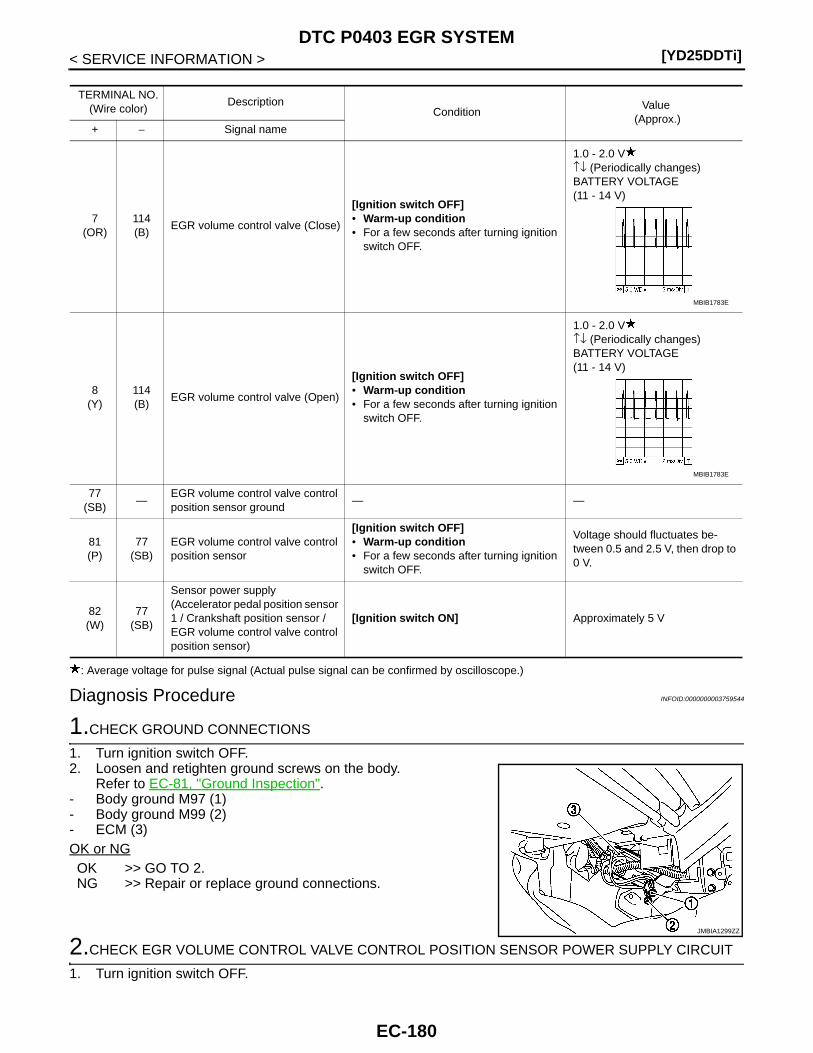
[YD25DDTi]DTC P0403 EGR SYSTEM
< SERVICE INFORMATION >
: Average voltage for pulse signal (Actual pulse signal can be confirmed by oscilloscope.)
Diagnosis Procedure INFOID:0000000003759544
1.CHECK GROUND CONNECTIONS
1. Turn ignition switch OFF.2. Loosen and retighten ground screws on the body.
Refer to EC-81, "Ground Inspection".- Body ground M97 (1)- Body ground M99 (2)- ECM (3)OK or NGOK >> GO TO 2.NG >> Repair or replace ground connections.
2.CHECK EGR VOLUME CONTROL VALVE CONTROL POSITION SENSOR POWER SUPPLY CIRCUIT
1. Turn ignition switch OFF.
TERMINAL NO.(Wire color)
DescriptionCondition
Value (Approx.)
+ − Signal name
7(OR)
114(B)
EGR volume control valve (Close)
[Ignition switch OFF]• Warm-up condition• For a few seconds after turning ignition
switch OFF.
1.0 - 2.0 V↑↓ (Periodically changes)BATTERY VOLTAGE(11 - 14 V)
8(Y)
114(B)
EGR volume control valve (Open)
[Ignition switch OFF]• Warm-up condition• For a few seconds after turning ignition
switch OFF.
1.0 - 2.0 V↑↓ (Periodically changes)BATTERY VOLTAGE(11 - 14 V)
77(SB)
—EGR volume control valve control position sensor ground
— —
81(P)
77(SB)
EGR volume control valve control position sensor
[Ignition switch OFF]• Warm-up condition• For a few seconds after turning ignition
switch OFF.
Voltage should fluctuates be-tween 0.5 and 2.5 V, then drop to 0 V.
82(W)
77(SB)
Sensor power supply(Accelerator pedal position sensor 1 / Crankshaft position sensor / EGR volume control valve control position sensor)
[Ignition switch ON] Approximately 5 V
MBIB1783E
MBIB1783E
JMBIA1299ZZ
EC-180
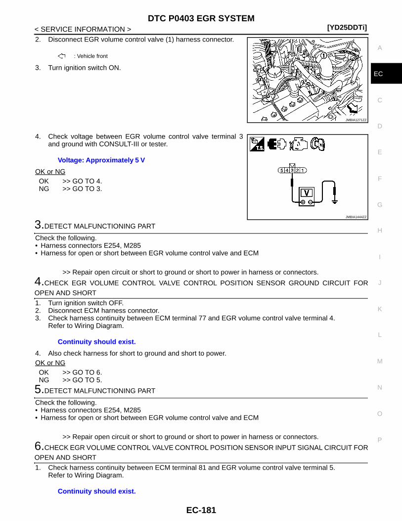
DTC P0403 EGR SYSTEM[YD25DDTi]
C
D
E
F
G
H
I
J
K
L
M
A
C
N
P
O
< SERVICE INFORMATION >
E
2. Disconnect EGR volume control valve (1) harness connector.
3. Turn ignition switch ON.
4. Check voltage between EGR volume control valve terminal 3and ground with CONSULT-III or tester.
OK or NGOK >> GO TO 4.NG >> GO TO 3.
3.DETECT MALFUNCTIONING PART
Check the following.• Harness connectors E254, M285• Harness for open or short between EGR volume control valve and ECM
>> Repair open circuit or short to ground or short to power in harness or connectors.
4.CHECK EGR VOLUME CONTROL VALVE CONTROL POSITION SENSOR GROUND CIRCUIT FOROPEN AND SHORT
1. Turn ignition switch OFF.2. Disconnect ECM harness connector.3. Check harness continuity between ECM terminal 77 and EGR volume control valve terminal 4.
Refer to Wiring Diagram.
4. Also check harness for short to ground and short to power.OK or NGOK >> GO TO 6.NG >> GO TO 5.
5.DETECT MALFUNCTIONING PART
Check the following.• Harness connectors E254, M285• Harness for open or short between EGR volume control valve and ECM
>> Repair open circuit or short to ground or short to power in harness or connectors.
6.CHECK EGR VOLUME CONTROL VALVE CONTROL POSITION SENSOR INPUT SIGNAL CIRCUIT FOROPEN AND SHORT
1. Check harness continuity between ECM terminal 81 and EGR volume control valve terminal 5.Refer to Wiring Diagram.
: Vehicle front
JMBIA1271ZZ
Voltage: Approximately 5 V
JMBIA1444ZZ
Continuity should exist.
Continuity should exist.
EC-181
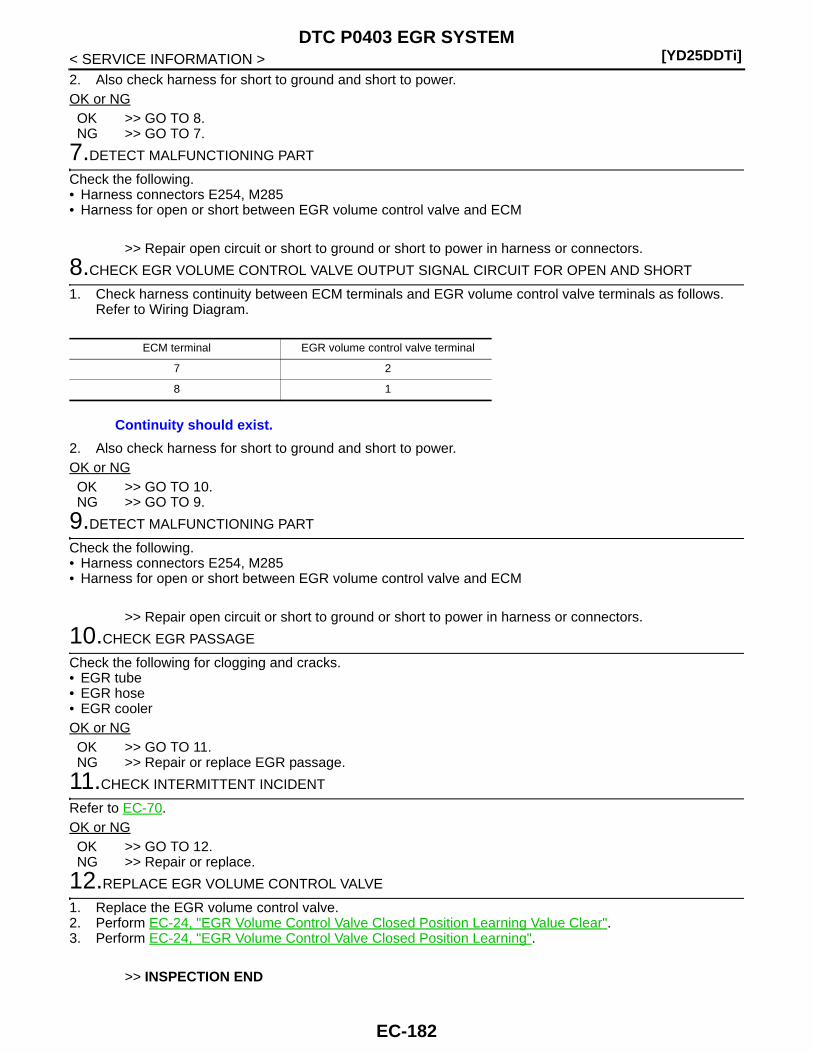
[YD25DDTi]DTC P0403 EGR SYSTEM
< SERVICE INFORMATION >2. Also check harness for short to ground and short to power.OK or NGOK >> GO TO 8.NG >> GO TO 7.
7.DETECT MALFUNCTIONING PART
Check the following.• Harness connectors E254, M285• Harness for open or short between EGR volume control valve and ECM
>> Repair open circuit or short to ground or short to power in harness or connectors.
8.CHECK EGR VOLUME CONTROL VALVE OUTPUT SIGNAL CIRCUIT FOR OPEN AND SHORT
1. Check harness continuity between ECM terminals and EGR volume control valve terminals as follows.Refer to Wiring Diagram.
2. Also check harness for short to ground and short to power.OK or NGOK >> GO TO 10.NG >> GO TO 9.
9.DETECT MALFUNCTIONING PART
Check the following.• Harness connectors E254, M285• Harness for open or short between EGR volume control valve and ECM
>> Repair open circuit or short to ground or short to power in harness or connectors.
10.CHECK EGR PASSAGE
Check the following for clogging and cracks.• EGR tube• EGR hose• EGR coolerOK or NGOK >> GO TO 11.NG >> Repair or replace EGR passage.
11.CHECK INTERMITTENT INCIDENT
Refer to EC-70.OK or NGOK >> GO TO 12.NG >> Repair or replace.
12.REPLACE EGR VOLUME CONTROL VALVE
1. Replace the EGR volume control valve.2. Perform EC-24, "EGR Volume Control Valve Closed Position Learning Value Clear".3. Perform EC-24, "EGR Volume Control Valve Closed Position Learning".
>> INSPECTION END
ECM terminal EGR volume control valve terminal
7 2
8 1
Continuity should exist.
EC-182
DTC P0403 EGR SYSTEM[YD25DDTi]
C
D
E
F
G
H
I
J
K
L
M
A
C
N
P
O
< SERVICE INFORMATION >
E
Removal and Installation INFOID:0000000003759545
EGR VOLUME CONTROL VALVERefer to EM-6.
EC-183
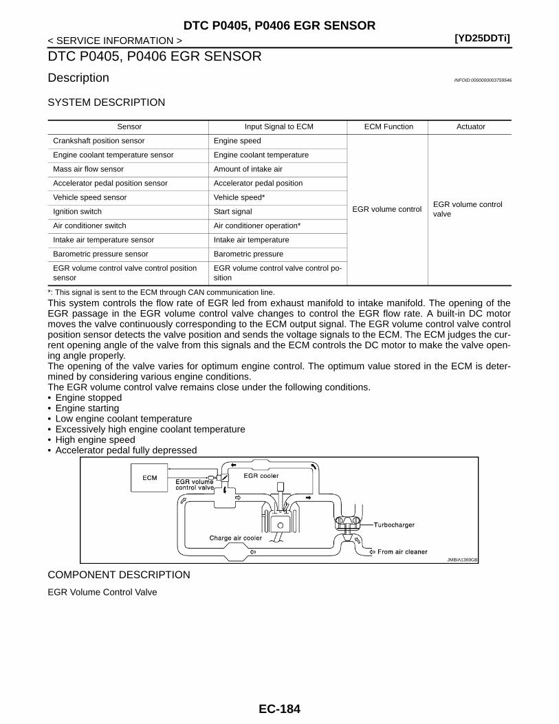
[YD25DDTi]DTC P0405, P0406 EGR SENSOR
< SERVICE INFORMATION >
DTC P0405, P0406 EGR SENSOR
Description INFOID:0000000003759546
SYSTEM DESCRIPTION
*: This signal is sent to the ECM through CAN communication line.
This system controls the flow rate of EGR led from exhaust manifold to intake manifold. The opening of theEGR passage in the EGR volume control valve changes to control the EGR flow rate. A built-in DC motormoves the valve continuously corresponding to the ECM output signal. The EGR volume control valve controlposition sensor detects the valve position and sends the voltage signals to the ECM. The ECM judges the cur-rent opening angle of the valve from this signals and the ECM controls the DC motor to make the valve open-ing angle properly.The opening of the valve varies for optimum engine control. The optimum value stored in the ECM is deter-mined by considering various engine conditions.The EGR volume control valve remains close under the following conditions.• Engine stopped• Engine starting• Low engine coolant temperature• Excessively high engine coolant temperature• High engine speed• Accelerator pedal fully depressed
COMPONENT DESCRIPTION
EGR Volume Control Valve
Sensor Input Signal to ECM ECM Function Actuator
Crankshaft position sensor Engine speed
EGR volume controlEGR volume control valve
Engine coolant temperature sensor Engine coolant temperature
Mass air flow sensor Amount of intake air
Accelerator pedal position sensor Accelerator pedal position
Vehicle speed sensor Vehicle speed*
Ignition switch Start signal
Air conditioner switch Air conditioner operation*
Intake air temperature sensor Intake air temperature
Barometric pressure sensor Barometric pressure
EGR volume control valve control position sensor
EGR volume control valve control po-sition
JMBIA1369GB
EC-184
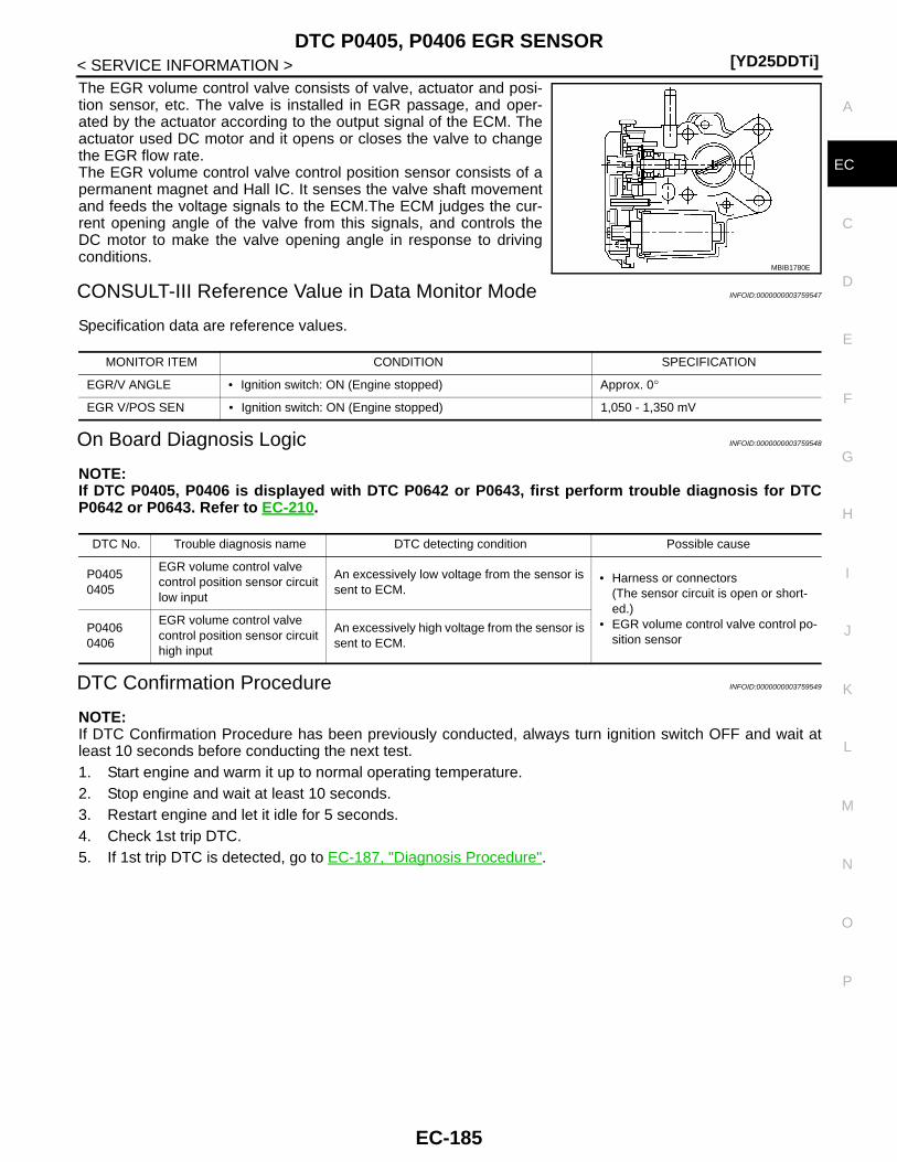
DTC P0405, P0406 EGR SENSOR[YD25DDTi]
C
D
E
F
G
H
I
J
K
L
M
A
C
N
P
O
< SERVICE INFORMATION >
E
The EGR volume control valve consists of valve, actuator and posi-tion sensor, etc. The valve is installed in EGR passage, and oper-ated by the actuator according to the output signal of the ECM. Theactuator used DC motor and it opens or closes the valve to changethe EGR flow rate.The EGR volume control valve control position sensor consists of apermanent magnet and Hall IC. It senses the valve shaft movementand feeds the voltage signals to the ECM.The ECM judges the cur-rent opening angle of the valve from this signals, and controls theDC motor to make the valve opening angle in response to drivingconditions.
CONSULT-III Reference Value in Data Monitor Mode INFOID:0000000003759547
Specification data are reference values.
On Board Diagnosis Logic INFOID:0000000003759548
NOTE:If DTC P0405, P0406 is displayed with DTC P0642 or P0643, first perform trouble diagnosis for DTCP0642 or P0643. Refer to EC-210.
DTC Confirmation Procedure INFOID:0000000003759549
NOTE:If DTC Confirmation Procedure has been previously conducted, always turn ignition switch OFF and wait atleast 10 seconds before conducting the next test.1. Start engine and warm it up to normal operating temperature.2. Stop engine and wait at least 10 seconds.3. Restart engine and let it idle for 5 seconds.4. Check 1st trip DTC.5. If 1st trip DTC is detected, go to EC-187, "Diagnosis Procedure".
MBIB1780E
MONITOR ITEM CONDITION SPECIFICATION
EGR/V ANGLE • Ignition switch: ON (Engine stopped) Approx. 0°
EGR V/POS SEN • Ignition switch: ON (Engine stopped) 1,050 - 1,350 mV
DTC No. Trouble diagnosis name DTC detecting condition Possible cause
P04050405
EGR volume control valve control position sensor circuit low input
An excessively low voltage from the sensor is sent to ECM.
• Harness or connectors(The sensor circuit is open or short-ed.)
• EGR volume control valve control po-sition sensor
P04060406
EGR volume control valve control position sensor circuit high input
An excessively high voltage from the sensor is sent to ECM.
EC-185

[YD25DDTi]DTC P0405, P0406 EGR SENSOR
< SERVICE INFORMATION >
Wiring Diagram INFOID:0000000003759550
Specification data are reference values and are measured between each terminal and ground.Pulse signal is measured by CONSULT-III.
GEC617A
EC-186
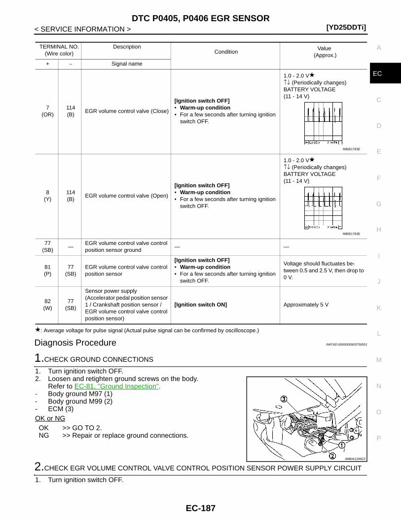
DTC P0405, P0406 EGR SENSOR[YD25DDTi]
C
D
E
F
G
H
I
J
K
L
M
A
C
N
P
O
< SERVICE INFORMATION >
E
: Average voltage for pulse signal (Actual pulse signal can be confirmed by oscilloscope.)
Diagnosis Procedure INFOID:0000000003759551
1.CHECK GROUND CONNECTIONS
1. Turn ignition switch OFF.2. Loosen and retighten ground screws on the body.
Refer to EC-81, "Ground Inspection".- Body ground M97 (1)- Body ground M99 (2)- ECM (3)OK or NGOK >> GO TO 2.NG >> Repair or replace ground connections.
2.CHECK EGR VOLUME CONTROL VALVE CONTROL POSITION SENSOR POWER SUPPLY CIRCUIT
1. Turn ignition switch OFF.
TERMINAL NO.(Wire color)
DescriptionCondition
Value (Approx.)
+ − Signal name
7(OR)
114(B)
EGR volume control valve (Close)
[Ignition switch OFF]• Warm-up condition• For a few seconds after turning ignition
switch OFF.
1.0 - 2.0 V↑↓ (Periodically changes)BATTERY VOLTAGE(11 - 14 V)
8(Y)
114(B)
EGR volume control valve (Open)
[Ignition switch OFF]• Warm-up condition• For a few seconds after turning ignition
switch OFF.
1.0 - 2.0 V↑↓ (Periodically changes)BATTERY VOLTAGE(11 - 14 V)
77(SB)
—EGR volume control valve control position sensor ground
— —
81(P)
77(SB)
EGR volume control valve control position sensor
[Ignition switch OFF]• Warm-up condition• For a few seconds after turning ignition
switch OFF.
Voltage should fluctuates be-tween 0.5 and 2.5 V, then drop to 0 V.
82(W)
77(SB)
Sensor power supply(Accelerator pedal position sensor 1 / Crankshaft position sensor / EGR volume control valve control position sensor)
[Ignition switch ON] Approximately 5 V
MBIB1783E
MBIB1783E
JMBIA1299ZZ
EC-187

[YD25DDTi]DTC P0405, P0406 EGR SENSOR
< SERVICE INFORMATION >2. Disconnect EGR volume control valve (1) harness connector.
3. Turn ignition switch ON.
4. Check voltage between EGR volume control valve terminal 3and ground with CONSULT-III or tester.
OK or NGOK >> GO TO 4.NG >> GO TO 3.
3.DETECT MALFUNCTIONING PART
Check the following.• Harness connectors E254, M285• Harness for open or short between EGR volume control valve and ECM
>> Repair open circuit or short to ground or short to power in harness or connectors.
4.CHECK EGR VOLUME CONTROL VALVE CONTROL POSITION SENSOR GROUND CIRCUIT FOROPEN AND SHORT
1. Turn ignition switch OFF.2. Disconnect ECM harness connector.3. Check harness continuity between ECM terminal 77 and EGR volume control valve terminal 4.
Refer to Wiring Diagram.
4. Also check harness for short to ground and short to power.OK or NGOK >> GO TO 6.NG >> GO TO 5.
5.DETECT MALFUNCTIONING PART
Check the following.• Harness connectors E254, M285• Harness for open or short between EGR volume control valve and ECM
>> Repair open circuit or short to ground or short to power in harness or connectors.
6.CHECK EGR VOLUME CONTROL VALVE CONTROL POSITION SENSOR INPUT SIGNAL CIRCUIT FOROPEN AND SHORT
1. Check harness continuity between ECM terminal 81 and EGR volume control valve terminal 5.Refer to Wiring Diagram.
: Vehicle front
JMBIA1271ZZ
Voltage: Approximately 5 V
JMBIA1444ZZ
Continuity should exist.
Continuity should exist.
EC-188

DTC P0405, P0406 EGR SENSOR[YD25DDTi]
C
D
E
F
G
H
I
J
K
L
M
A
C
N
P
O
< SERVICE INFORMATION >
E
2. Also check harness for short to ground and short to power.OK or NGOK >> GO TO 8.NG >> GO TO 7.
7.DETECT MALFUNCTIONING PART
Check the following.• Harness connectors E254, M285• Harness for open or short between EGR volume control valve and ECM
>> Repair open circuit or short to ground or short to power in harness or connectors.
8.CHECK INTERMITTENT INCIDENT
Refer to EC-70.OK or NGOK >> GO TO 9.NG >> Repair or replace.
9.REPLACE EGR VOLUME CONTROL VALVE
1. Replace the EGR volume control valve.2. Perform EC-24, "EGR Volume Control Valve Closed Position Learning Value Clear".3. Perform EC-24, "EGR Volume Control Valve Closed Position Learning".
>> INSPECTION END
Removal and Installation INFOID:0000000003759552
EGR VOLUME CONTROL VALVERefer to EM-6.
EC-189

[YD25DDTi]DTC P0409 EGR SYSTEM
< SERVICE INFORMATION >
DTC P0409 EGR SYSTEM
Description INFOID:0000000003759553
SYSTEM DESCRIPTION
*: This signal is sent to the ECM through CAN communication line.
This system controls the flow rate of EGR led from exhaust manifold to intake manifold. The opening of theEGR passage in the EGR volume control valve changes to control the EGR flow rate. A built-in DC motormoves the valve continuously corresponding to the ECM output signal. The EGR volume control valve controlposition sensor detects the valve position and sends the voltage signals to the ECM. The ECM judges the cur-rent opening angle of the valve from this signals and the ECM controls the DC motor to make the valve open-ing angle properly.The opening of the valve varies for optimum engine control. The optimum value stored in the ECM is deter-mined by considering various engine conditions.The EGR volume control valve remains close under the following conditions.• Engine stopped• Engine starting• Low engine coolant temperature• Excessively high engine coolant temperature• High engine speed• Accelerator pedal fully depressed
COMPONENT DESCRIPTION
EGR Volume Control Valve
Sensor Input Signal to ECM ECM Function Actuator
Crankshaft position sensor Engine speed
EGR volume controlEGR volume control valve
Engine coolant temperature sensor Engine coolant temperature
Mass air flow sensor Amount of intake air
Accelerator pedal position sensor Accelerator pedal position
Vehicle speed sensor Vehicle speed*
Ignition switch Start signal
Air conditioner switch Air conditioner operation*
Intake air temperature sensor Intake air temperature
Barometric pressure sensor Barometric pressure
EGR volume control valve control position sensor
EGR volume control valve control po-sition
JMBIA1369GB
EC-190

DTC P0409 EGR SYSTEM[YD25DDTi]
C
D
E
F
G
H
I
J
K
L
M
A
C
N
P
O
< SERVICE INFORMATION >
E
The EGR volume control valve consists of valve, actuator and posi-tion sensor, etc. The valve is installed in EGR passage, and oper-ated by the actuator according to the output signal of the ECM. Theactuator used DC motor and it opens or closes the valve to changethe EGR flow rate.The EGR volume control valve control position sensor consists of apermanent magnet and Hall IC. It senses the valve shaft movementand feeds the voltage signals to the ECM.The ECM judges the cur-rent opening angle of the valve from this signals, and controls theDC motor to make the valve opening angle in response to drivingconditions.
CONSULT-III Reference Value in Data Monitor Mode INFOID:0000000003759554
Specification data are reference values.
On Board Diagnosis Logic INFOID:0000000003759555
NOTE:If DTC P0409 is displayed with DTC P0642 or P0643, first perform trouble diagnosis for DTC P0642 orP0643. Refer to EC-210.
DTC Confirmation Procedure INFOID:0000000003759556
NOTE:If DTC Confirmation Procedure has been previously conducted, always turn ignition switch OFF and wait atleast 10 seconds before conducting the next test.
WITH CONSULT-III1. Start engine and warm it up to normal operating temperature.2. Select “DATA MONITOR” mode with CONSULT-III.3. Confirm that engine coolant temperature is more than 81°C (178°F).4. Stop engine and wait at least 10 seconds.5. Restart engine and let it idle for 5 seconds.6. Check 1st trip DTC.7. If 1st trip DTC is detected, go to EC-193, "Diagnosis Procedure".
WITH GSTFollow the procedure “WITH CONSULT-III” above.
MBIB1780E
MONITOR ITEM CONDITION SPECIFICATION
EGR/V ANGLE • Ignition switch: ON (Engine stopped) Approx. 0°
EGR V/POS SEN • Ignition switch: ON (Engine stopped) 1,050 - 1,350 mV
DTC No. Trouble diagnosis name DTC detecting condition Possible cause
P04090409
EGR volume control valve does not operate properly.
The characteristic of EGR volume con-trol valve is not in the specified range.
• Harness or connectors(EGR volume control valve circuit is open or shorted.)
• EGR volume control valve
EC-191

[YD25DDTi]DTC P0409 EGR SYSTEM
< SERVICE INFORMATION >
Wiring Diagram INFOID:0000000003759557
Specification data are reference values and are measured between each terminal and ground.Pulse signal is measured by CONSULT-III.
GEC616A
EC-192

DTC P0409 EGR SYSTEM[YD25DDTi]
C
D
E
F
G
H
I
J
K
L
M
A
C
N
P
O
< SERVICE INFORMATION >
E
: Average voltage for pulse signal (Actual pulse signal can be confirmed by oscilloscope.)
Diagnosis Procedure INFOID:0000000003759558
1.CHECK GROUND CONNECTIONS
1. Turn ignition switch OFF.2. Loosen and retighten ground screws on the body.
Refer to EC-81, "Ground Inspection".- Body ground M97 (1)- Body ground M99 (2)- ECM (3)OK or NGOK >> GO TO 2.NG >> Repair or replace ground connections.
2.CHECK EGR VOLUME CONTROL VALVE CONTROL POSITION SENSOR POWER SUPPLY CIRCUIT
1. Turn ignition switch OFF.
TERMINAL NO.(Wire color)
DescriptionCondition
Value (Approx.)
+ − Signal name
7(OR)
114(B)
EGR volume control valve (Close)
[Ignition switch OFF]• Warm-up condition• For a few seconds after turning ignition
switch OFF.
1.0 - 2.0 V↑↓ (Periodically changes)BATTERY VOLTAGE(11 - 14 V)
8(Y)
114(B)
EGR volume control valve (Open)
[Ignition switch OFF]• Warm-up condition• For a few seconds after turning ignition
switch OFF.
1.0 - 2.0 V↑↓ (Periodically changes)BATTERY VOLTAGE(11 - 14 V)
77(SB)
—EGR volume control valve control position sensor ground
— —
81(P)
77(SB)
EGR volume control valve control position sensor
[Ignition switch OFF]• Warm-up condition• For a few seconds after turning ignition
switch OFF.
Voltage should fluctuates be-tween 0.5 and 2.5 V, then drop to 0 V.
82(W)
77(SB)
Sensor power supply(Accelerator pedal position sensor 1 / Crankshaft position sensor / EGR volume control valve control position sensor)
[Ignition switch ON] Approximately 5 V
MBIB1783E
MBIB1783E
JMBIA1299ZZ
EC-193

[YD25DDTi]DTC P0409 EGR SYSTEM
< SERVICE INFORMATION >2. Disconnect EGR volume control valve (1) harness connector.
3. Turn ignition switch ON.
4. Check voltage between EGR volume control valve terminal 3and ground with CONSULT-III or tester.
OK or NGOK >> GO TO 4.NG >> GO TO 3.
3.DETECT MALFUNCTIONING PART
Check the following.• Harness connectors E254, M285• Harness for open or short between EGR volume control valve and ECM
>> Repair open circuit or short to ground or short to power in harness or connectors.
4.CHECK EGR VOLUME CONTROL VALVE CONTROL POSITION SENSOR GROUND CIRCUIT FOROPEN AND SHORT
1. Turn ignition switch OFF.2. Disconnect ECM harness connector.3. Check harness continuity between ECM terminal 77 and EGR volume control valve terminal 4.
Refer to Wiring Diagram.
4. Also check harness for short to ground and short to power.OK or NGOK >> GO TO 6.NG >> GO TO 5.
5.DETECT MALFUNCTIONING PART
Check the following.• Harness connectors E254, M285• Harness for open or short between EGR volume control valve and ECM
>> Repair open circuit or short to ground or short to power in harness or connectors.
6.CHECK EGR VOLUME CONTROL VALVE CONTROL POSITION SENSOR INPUT SIGNAL CIRCUIT FOROPEN AND SHORT
1. Check harness continuity between ECM terminal 81 and EGR volume control valve terminal 5.Refer to Wiring Diagram.
: Vehicle front
JMBIA1271ZZ
Voltage: Approximately 5 V
JMBIA1444ZZ
Continuity should exist.
Continuity should exist.
EC-194

DTC P0409 EGR SYSTEM[YD25DDTi]
C
D
E
F
G
H
I
J
K
L
M
A
C
N
P
O
< SERVICE INFORMATION >
E
2. Also check harness for short to ground and short to power.OK or NGOK >> GO TO 8.NG >> GO TO 7.
7.DETECT MALFUNCTIONING PART
Check the following.• Harness connectors E254, M285• Harness for open or short between EGR volume control valve and ECM
>> Repair open circuit or short to ground or short to power in harness or connectors.
8.CHECK EGR VOLUME CONTROL VALVE OUTPUT SIGNAL CIRCUIT FOR OPEN AND SHORT
1. Check harness continuity between ECM terminals and EGR volume control valve terminals as follows.Refer to Wiring Diagram.
2. Also check harness for short to ground and short to power.OK or NGOK >> GO TO 10.NG >> GO TO 9.
9.DETECT MALFUNCTIONING PART
Check the following.• Harness connectors E254, M285• Harness for open or short between EGR volume control valve and ECM
>> Repair open circuit or short to ground or short to power in harness or connectors.
10.CHECK INTERMITTENT INCIDENT
Refer to EC-70.OK or NGOK >> GO TO 11.NG >> Repair or replace.
11.REPLACE EGR VOLUME CONTROL VALVE
1. Replace the EGR volume control valve.2. Perform EC-24, "EGR Volume Control Valve Closed Position Learning Value Clear".3. Perform EC-24, "EGR Volume Control Valve Closed Position Learning".
>> INSPECTION END
Removal and Installation INFOID:0000000003759559
EGR VOLUME CONTROL VALVERefer to EM-6.
ECM terminal EGR volume control valve terminal
7 2
8 1
Continuity should exist.
EC-195

[YD25DDTi]DTC P0488 EGR SYSTEM
< SERVICE INFORMATION >
DTC P0488 EGR SYSTEM
Description INFOID:0000000003759601
SYSTEM DESCRIPTION
*: This signal is sent to the ECM through CAN communication line.
This system controls the flow rate of EGR led from exhaust manifold to intake manifold. The opening of theEGR passage in the EGR volume control valve changes to control the EGR flow rate. A built-in DC motormoves the valve continuously corresponding to the ECM output signal. The EGR volume control valve controlposition sensor detects the valve position and sends the voltage signals to the ECM. The ECM judges the cur-rent opening angle of the valve from this signals and the ECM controls the DC motor to make the valve open-ing angle properly.The opening of the valve varies for optimum engine control. The optimum value stored in the ECM is deter-mined by considering various engine conditions.The EGR volume control valve remains close under the following conditions.• Engine stopped• Engine starting• Low engine coolant temperature• Excessively high engine coolant temperature• High engine speed• Accelerator pedal fully depressed
COMPONENT DESCRIPTION
EGR Volume Control Valve
Sensor Input Signal to ECM ECM Function Actuator
Crankshaft position sensor Engine speed
EGR volume controlEGR volume control valve
Engine coolant temperature sensor Engine coolant temperature
Mass air flow sensor Amount of intake air
Accelerator pedal position sensor Accelerator pedal position
Vehicle speed sensor Vehicle speed*
Ignition switch Start signal
Air conditioner switch Air conditioner operation*
Intake air temperature sensor Intake air temperature
Barometric pressure sensor Barometric pressure
EGR volume control valve control position sensor
EGR volume control valve control po-sition
JMBIA1369GB
EC-196
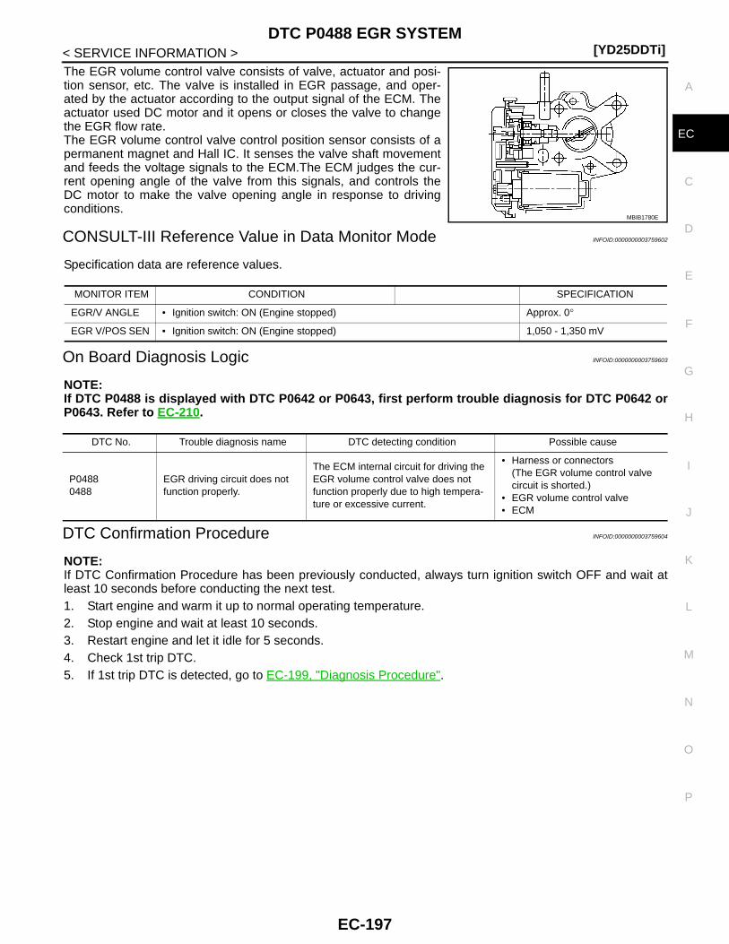
DTC P0488 EGR SYSTEM[YD25DDTi]
C
D
E
F
G
H
I
J
K
L
M
A
C
N
P
O
< SERVICE INFORMATION >
E
The EGR volume control valve consists of valve, actuator and posi-tion sensor, etc. The valve is installed in EGR passage, and oper-ated by the actuator according to the output signal of the ECM. Theactuator used DC motor and it opens or closes the valve to changethe EGR flow rate.The EGR volume control valve control position sensor consists of apermanent magnet and Hall IC. It senses the valve shaft movementand feeds the voltage signals to the ECM.The ECM judges the cur-rent opening angle of the valve from this signals, and controls theDC motor to make the valve opening angle in response to drivingconditions.
CONSULT-III Reference Value in Data Monitor Mode INFOID:0000000003759602
Specification data are reference values.
On Board Diagnosis Logic INFOID:0000000003759603
NOTE:If DTC P0488 is displayed with DTC P0642 or P0643, first perform trouble diagnosis for DTC P0642 orP0643. Refer to EC-210.
DTC Confirmation Procedure INFOID:0000000003759604
NOTE:If DTC Confirmation Procedure has been previously conducted, always turn ignition switch OFF and wait atleast 10 seconds before conducting the next test.1. Start engine and warm it up to normal operating temperature.2. Stop engine and wait at least 10 seconds.3. Restart engine and let it idle for 5 seconds.4. Check 1st trip DTC.5. If 1st trip DTC is detected, go to EC-199, "Diagnosis Procedure".
MBIB1780E
MONITOR ITEM CONDITION SPECIFICATION
EGR/V ANGLE • Ignition switch: ON (Engine stopped) Approx. 0°
EGR V/POS SEN • Ignition switch: ON (Engine stopped) 1,050 - 1,350 mV
DTC No. Trouble diagnosis name DTC detecting condition Possible cause
P04880488
EGR driving circuit does not function properly.
The ECM internal circuit for driving the EGR volume control valve does not function properly due to high tempera-ture or excessive current.
• Harness or connectors(The EGR volume control valve circuit is shorted.)
• EGR volume control valve• ECM
EC-197
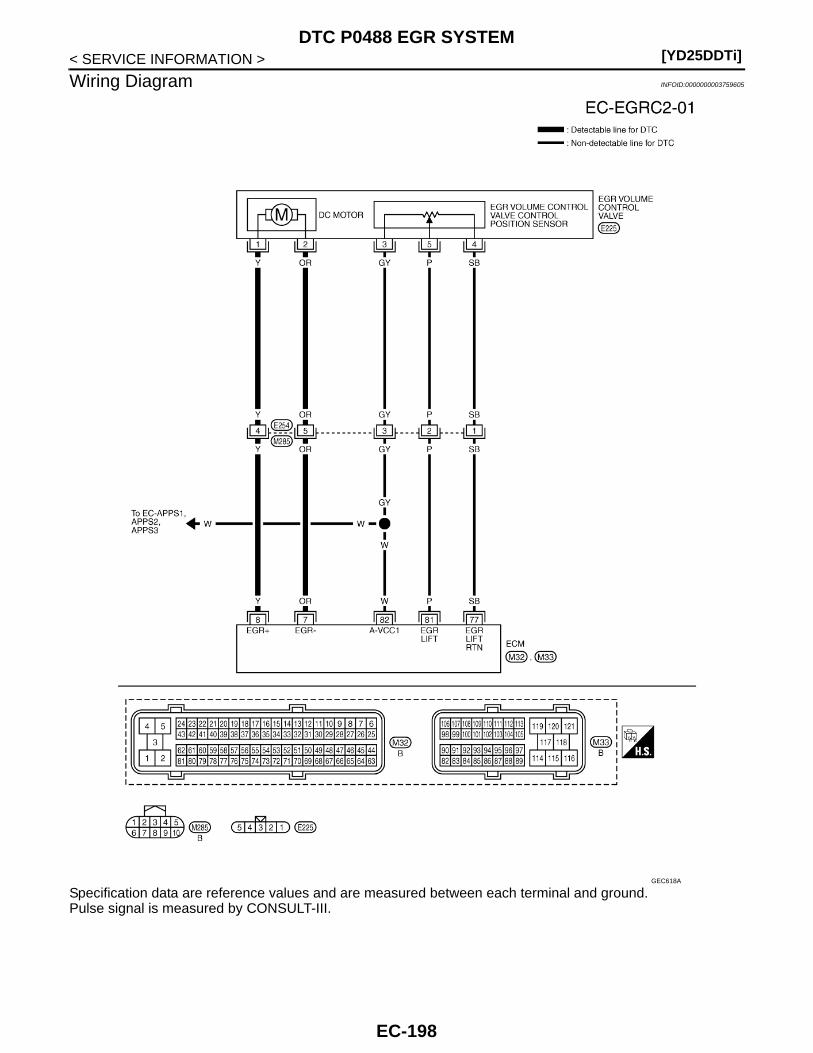
[YD25DDTi]DTC P0488 EGR SYSTEM
< SERVICE INFORMATION >
Wiring Diagram INFOID:0000000003759605
Specification data are reference values and are measured between each terminal and ground.Pulse signal is measured by CONSULT-III.
GEC618A
EC-198

DTC P0488 EGR SYSTEM[YD25DDTi]
C
D
E
F
G
H
I
J
K
L
M
A
C
N
P
O
< SERVICE INFORMATION >
E
: Average voltage for pulse signal (Actual pulse signal can be confirmed by oscilloscope.)
Diagnosis Procedure INFOID:0000000003759606
1.CHECK GROUND CONNECTIONS
1. Turn ignition switch OFF.2. Loosen and retighten ground screws on the body.
Refer to EC-81, "Ground Inspection".- Body ground M97 (1)- Body ground M99 (2)- ECM (3)OK or NGOK >> GO TO 2.NG >> Repair or replace ground connections.
2.CHECK EGR VOLUME CONTROL VALVE OUTPUT SIGNAL CIRCUIT FOR OPEN AND SHORT
TERMINAL NO.(Wire color)
DescriptionCondition
Value (Approx.)
+ − Signal name
7(OR)
114(B)
EGR volume control valve (Close)
[Ignition switch OFF]• Warm-up condition• For a few seconds after turning ignition
switch OFF.
1.0 - 2.0 V↑↓ (Periodically changes)BATTERY VOLTAGE(11 - 14 V)
8(Y)
114(B)
EGR volume control valve (Open)
[Ignition switch OFF]• Warm-up condition• For a few seconds after turning ignition
switch OFF.
1.0 - 2.0 V↑↓ (Periodically changes)BATTERY VOLTAGE(11 - 14 V)
77(SB)
—EGR volume control valve control position sensor ground
— —
81(P)
77(SB)
EGR volume control valve control position sensor
[Ignition switch OFF]• Warm-up condition• For a few seconds after turning ignition
switch OFF.
Voltage should fluctuates be-tween 0.5 and 2.5 V, then drop to 0 V.
82(W)
77(SB)
Sensor power supply(Accelerator pedal position sensor 1 / Crankshaft position sensor / EGR volume control valve control position sensor)
[Ignition switch ON] Approximately 5 V
MBIB1783E
MBIB1783E
JMBIA1299ZZ
EC-199

[YD25DDTi]DTC P0488 EGR SYSTEM
< SERVICE INFORMATION >1. Disconnect EGR volume control valve (1) harness connector.
2. Disconnect ECM harness connector.3. Check harness continuity between ECM terminals and EGR vol-
ume control valve terminals as follows.Refer to Wiring Diagram.
4. Also check harness for short to ground and short to power.OK or NGOK >> GO TO 3.NG >> Repair open circuit or short to ground or short to power in harness or connectors.
3.CHECK INTERMITTENT INCIDENT
Refer to EC-70.OK or NGOK >> GO TO 4.NG >> Repair or replace.
4.REPLACE EGR VOLUME CONTROL VALVE
1. Replace the EGR volume control valve.2. Perform EC-24, "EGR Volume Control Valve Closed Position Learning Value Clear".3. Perform EC-24, "EGR Volume Control Valve Closed Position Learning".
>> INSPECTION END
Removal and Installation INFOID:0000000003759607
EGR VOLUME CONTROL VALVERefer to EM-6.
: Vehicle front
ECM terminal EGR volume control valve terminal
7 2
8 1
Continuity should exist.
JMBIA1271ZZ
EC-200

DTC P0563 BATTERY VOLTAGE[YD25DDTi]
C
D
E
F
G
H
I
J
K
L
M
A
C
N
P
O
< SERVICE INFORMATION >
E
DTC P0563 BATTERY VOLTAGE
On Board Diagnosis Logic INFOID:0000000003759627
This self-diagnosis has the one trip detection logic.MI will not light up for this self-diagnosis.
DTC Confirmation Procedure INFOID:0000000003759628
NOTE:If DTC Confirmation Procedure has been previously conducted, always turn ignition switch OFF and wait atleast 10 seconds before conducting the next test. 1. Start engine and let it idle for at least 35 seconds.2. Check DTC.3. If DTC is detected, go to EC-201, "Diagnosis Procedure".
Diagnosis Procedure INFOID:0000000003759629
1.INSPECTION START
Are jumper cables connected for the jump starting?Yes or NoYes >> GO TO 3.No >> GO TO 2.
2.CHECK BATTERY AND ALTERNATOR
Check that the proper type of battery and type of alternator are installed.Refer to “BATTERY” and “CHARGING SYSTEM” in EL section.OK or NGOK >> GO TO 5.NG >> Replace with a proper one.
3.CHECK JUMPER CABLES INSTALLATION
Check that the jumper cables are connected in the correct sequence.
OK or NGOK >> GO TO 4.NG >> Reconnect jumper cables properly.
4.CHECK BATTERY FOR BOOSTER
Check that the battery for the booster is a 12 V battery.OK or NGOK >> GO TO 5.
DTC No. Trouble diagnosis name DTC detecting condition Possible cause
P05630563
Battery voltage highAn excessively high voltage from the battery is sent to ECM.
• Battery• Battery terminal• Alternator• Incorrect jump starting
SEF439Z
EC-201
[YD25DDTi]DTC P0563 BATTERY VOLTAGE
< SERVICE INFORMATION >NG >> Change the vehicle for booster.
5.PERFORM DTC CONFIRMATION PROCEDURE AGAIN
With CONSULT-III1. Turn ignition switch ON.2. Select “SELF DIAG RESULTS” mode with CONSULT-III.3. Touch “ERASE”.4. Perform EC-201, "DTC Confirmation Procedure", again.5. Is DTC P0563 displayed again?
With GST1. Turn ignition switch ON.2. Select Service $04 with GST.3. Perform EC-201, "DTC Confirmation Procedure", again.4. Is DTC P0563 displayed again?Yes or NoYes >> GO TO 6.No >> GO TO 7.
6.REPLACE ECM
1. Replace ECM.2. Perform initialization of NATS system and registration of all NATS ignition key IDs. Refer to EL-96, "ECM
Re-communicating Function".3. Perform Injector Adjustment Value Registration. Refer to EC-22, "Injector Adjustment Value Registration".4. Perform Fuel Pump Learning Value Clearing. Refer to EC-23, "Fuel Pump Learning Value Clearing".5. Perform EGR Volume Control Valve Closed Position Learning Value Clear. Refer to EC-24, "EGR Volume
Control Valve Closed Position Learning Value Clear".6. Perform EGR Volume Control Valve Closed Position Learning. Refer to EC-24, "EGR Volume Control
Valve Closed Position Learning".
>> INSPECTION END
7.CHECK ELECTRICAL PARTS DAMAGE
Check the following for damage.• Wiring harness and harness connectors for burn• Fuses for shortOK or NGOK >> INSPECTION ENDNG >> Repair or replace malfunctioning part.
EC-202
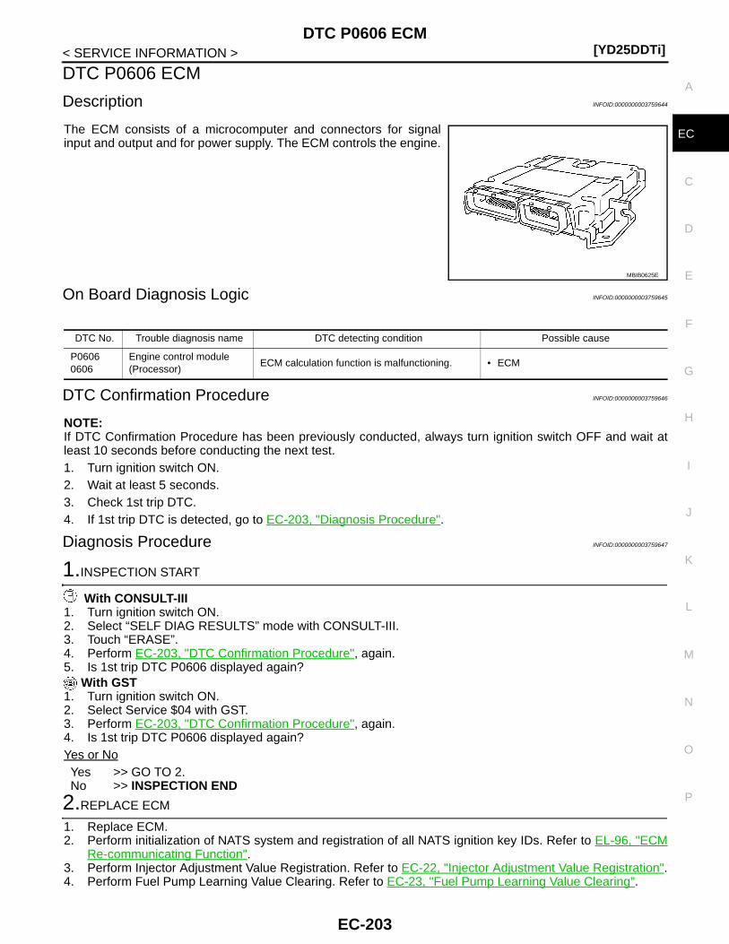
DTC P0606 ECM[YD25DDTi]
C
D
E
F
G
H
I
J
K
L
M
A
C
N
P
O
< SERVICE INFORMATION >
E
DTC P0606 ECM
Description INFOID:0000000003759644
The ECM consists of a microcomputer and connectors for signalinput and output and for power supply. The ECM controls the engine.
On Board Diagnosis Logic INFOID:0000000003759645
DTC Confirmation Procedure INFOID:0000000003759646
NOTE:If DTC Confirmation Procedure has been previously conducted, always turn ignition switch OFF and wait atleast 10 seconds before conducting the next test.1. Turn ignition switch ON.2. Wait at least 5 seconds.3. Check 1st trip DTC.4. If 1st trip DTC is detected, go to EC-203, "Diagnosis Procedure".
Diagnosis Procedure INFOID:0000000003759647
1.INSPECTION START
With CONSULT-III1. Turn ignition switch ON.2. Select “SELF DIAG RESULTS” mode with CONSULT-III.3. Touch “ERASE”.4. Perform EC-203, "DTC Confirmation Procedure", again.5. Is 1st trip DTC P0606 displayed again?
With GST1. Turn ignition switch ON.2. Select Service $04 with GST.3. Perform EC-203, "DTC Confirmation Procedure", again.4. Is 1st trip DTC P0606 displayed again?Yes or NoYes >> GO TO 2.No >> INSPECTION END
2.REPLACE ECM
1. Replace ECM.2. Perform initialization of NATS system and registration of all NATS ignition key IDs. Refer to EL-96, "ECM
Re-communicating Function".3. Perform Injector Adjustment Value Registration. Refer to EC-22, "Injector Adjustment Value Registration".4. Perform Fuel Pump Learning Value Clearing. Refer to EC-23, "Fuel Pump Learning Value Clearing".
MBIB0625E
DTC No. Trouble diagnosis name DTC detecting condition Possible cause
P06060606
Engine control module (Processor)
ECM calculation function is malfunctioning. • ECM
EC-203
[YD25DDTi]DTC P0606 ECM
< SERVICE INFORMATION >5. Perform EGR Volume Control Valve Closed Position Learning Value Clear. Refer to EC-24, "EGR Volume
Control Valve Closed Position Learning Value Clear".6. Perform EGR Volume Control Valve Closed Position Learning. Refer to EC-24, "EGR Volume Control
Valve Closed Position Learning".
>> INSPECTION END
EC-204
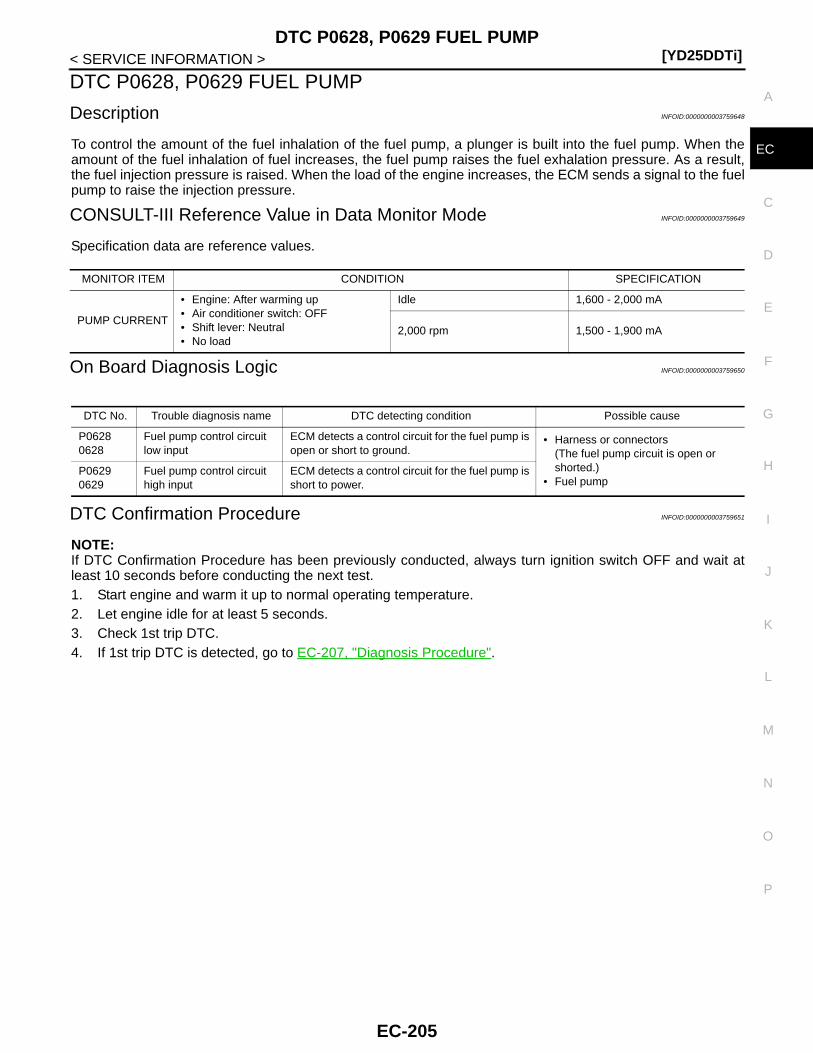
DTC P0628, P0629 FUEL PUMP[YD25DDTi]
C
D
E
F
G
H
I
J
K
L
M
A
C
N
P
O
< SERVICE INFORMATION >
E
DTC P0628, P0629 FUEL PUMP
Description INFOID:0000000003759648
To control the amount of the fuel inhalation of the fuel pump, a plunger is built into the fuel pump. When theamount of the fuel inhalation of fuel increases, the fuel pump raises the fuel exhalation pressure. As a result,the fuel injection pressure is raised. When the load of the engine increases, the ECM sends a signal to the fuelpump to raise the injection pressure.
CONSULT-III Reference Value in Data Monitor Mode INFOID:0000000003759649
Specification data are reference values.
On Board Diagnosis Logic INFOID:0000000003759650
DTC Confirmation Procedure INFOID:0000000003759651
NOTE:If DTC Confirmation Procedure has been previously conducted, always turn ignition switch OFF and wait atleast 10 seconds before conducting the next test. 1. Start engine and warm it up to normal operating temperature.2. Let engine idle for at least 5 seconds.3. Check 1st trip DTC.4. If 1st trip DTC is detected, go to EC-207, "Diagnosis Procedure".
MONITOR ITEM CONDITION SPECIFICATION
PUMP CURRENT
• Engine: After warming up• Air conditioner switch: OFF• Shift lever: Neutral• No load
Idle 1,600 - 2,000 mA
2,000 rpm 1,500 - 1,900 mA
DTC No. Trouble diagnosis name DTC detecting condition Possible cause
P06280628
Fuel pump control circuit low input
ECM detects a control circuit for the fuel pump is open or short to ground.
• Harness or connectors(The fuel pump circuit is open or shorted.)
• Fuel pumpP06290629
Fuel pump control circuit high input
ECM detects a control circuit for the fuel pump is short to power.
EC-205

[YD25DDTi]DTC P0628, P0629 FUEL PUMP
< SERVICE INFORMATION >
Wiring Diagram INFOID:0000000003759652
Specification data are reference values and are measured between each terminal and ground.Pulse signal is measured by CONSULT-III.
GEC621A
EC-206

DTC P0628, P0629 FUEL PUMP[YD25DDTi]
C
D
E
F
G
H
I
J
K
L
M
A
C
N
P
O
< SERVICE INFORMATION >
E
Diagnosis Procedure INFOID:0000000003759653
1.CHECK ECM OUTPUT SIGNAL CIRCUIT FOR OPEN AND SHORT
1. Turn ignition switch OFF.2. Disconnect fuel pump (2) harness connector.- Fuel pump temperature sensor (1)3. Disconnect ECM harness connector.4. Check harness continuity between ECM terminal 10 and fuel
pump terminal 1.Refer to Wiring Diagram.
5. Also check harness for short to ground and short to power.OK or NGOK >> GO TO 3.NG >> GO TO 2.
2.DETECT MALFUNCTIONING PART
Check the following.• Harness connectors E237, M279
TERMINAL NO.(Wire color)
DescriptionCondition
Value (Approx.)
+ − Signal name
10(G)
114(B)
Fuel pump
[Engine is running]• Warm-up condition• Idle speed
Approximately 5.8 V
[Engine is running]• Warm-up condition• Engine speed: 2,000 rpm
Approximately 5.5 V
29(B)
114(B)
Fuel pump
[Engine is running]• Warm-up condition• Idle speed
Approximately 0.3 V
[Engine is running]• Warm-up condition• Engine speed: 2,000 rpm
Approximately 0.3 V
MBIB0885E
MBIB0886E
MBIB0887E
MBIB0888E
Continuity should exist.
MBIB1751E
EC-207
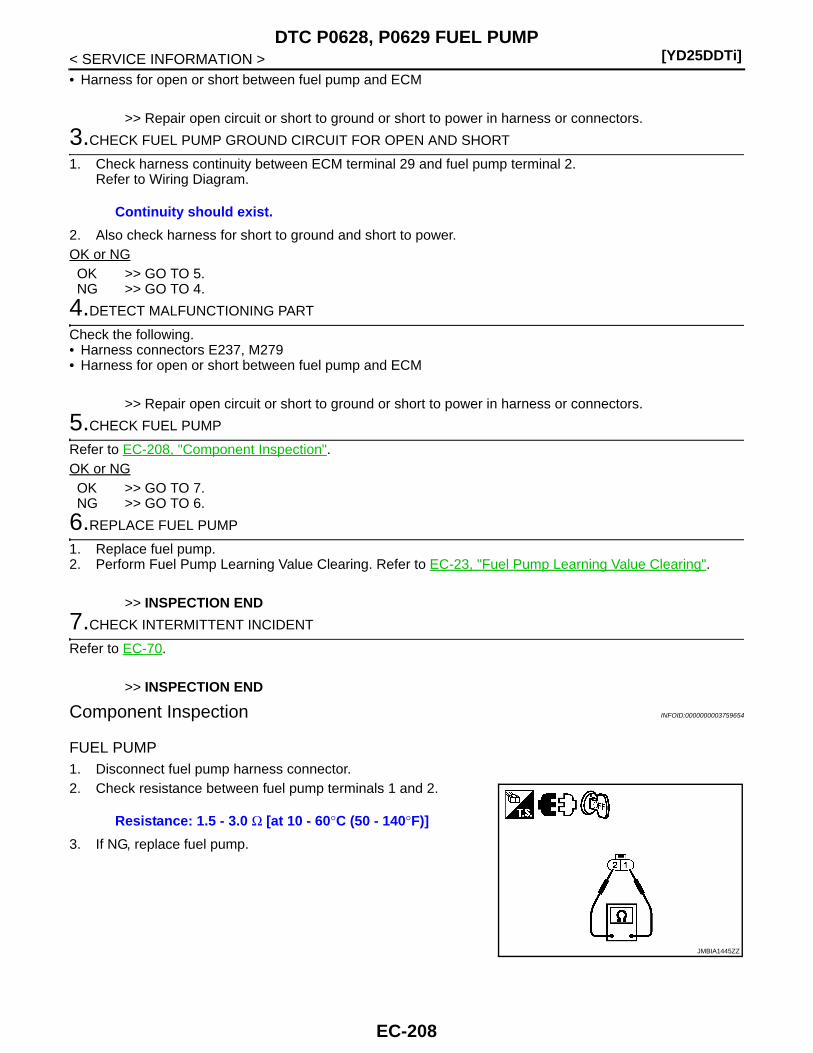
[YD25DDTi]DTC P0628, P0629 FUEL PUMP
< SERVICE INFORMATION >• Harness for open or short between fuel pump and ECM
>> Repair open circuit or short to ground or short to power in harness or connectors.
3.CHECK FUEL PUMP GROUND CIRCUIT FOR OPEN AND SHORT
1. Check harness continuity between ECM terminal 29 and fuel pump terminal 2. Refer to Wiring Diagram.
2. Also check harness for short to ground and short to power.OK or NGOK >> GO TO 5.NG >> GO TO 4.
4.DETECT MALFUNCTIONING PART
Check the following.• Harness connectors E237, M279• Harness for open or short between fuel pump and ECM
>> Repair open circuit or short to ground or short to power in harness or connectors.
5.CHECK FUEL PUMP
Refer to EC-208, "Component Inspection".OK or NGOK >> GO TO 7.NG >> GO TO 6.
6.REPLACE FUEL PUMP
1. Replace fuel pump.2. Perform Fuel Pump Learning Value Clearing. Refer to EC-23, "Fuel Pump Learning Value Clearing".
>> INSPECTION END
7.CHECK INTERMITTENT INCIDENT
Refer to EC-70.
>> INSPECTION END
Component Inspection INFOID:0000000003759654
FUEL PUMP1. Disconnect fuel pump harness connector.2. Check resistance between fuel pump terminals 1 and 2.
3. If NG, replace fuel pump.
Continuity should exist.
Resistance: 1.5 - 3.0 Ω [at 10 - 60°C (50 - 140°F)]
JMBIA1445ZZ
EC-208
DTC P0628, P0629 FUEL PUMP[YD25DDTi]
C
D
E
F
G
H
I
J
K
L
M
A
C
N
P
O
< SERVICE INFORMATION >
E
Removal and Installation INFOID:0000000003759655
FUEL PUMPRefer to EC-24.
EC-209
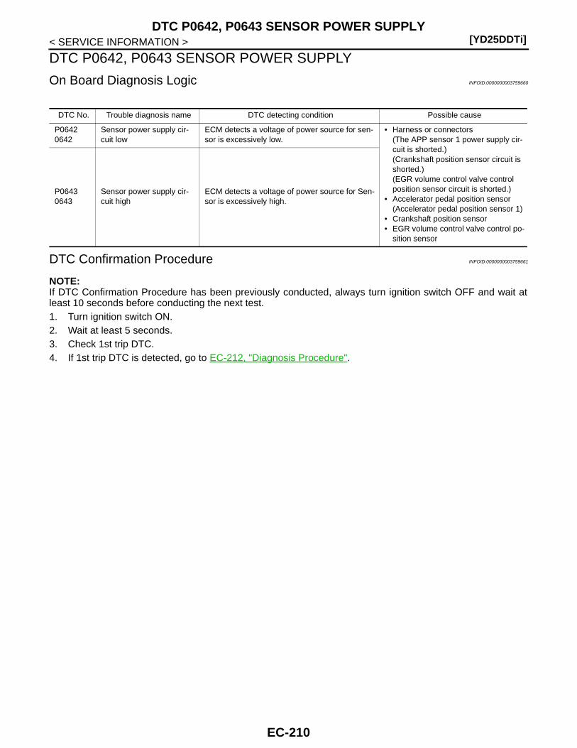
[YD25DDTi]DTC P0642, P0643 SENSOR POWER SUPPLY
< SERVICE INFORMATION >
DTC P0642, P0643 SENSOR POWER SUPPLY
On Board Diagnosis Logic INFOID:0000000003759660
DTC Confirmation Procedure INFOID:0000000003759661
NOTE:If DTC Confirmation Procedure has been previously conducted, always turn ignition switch OFF and wait atleast 10 seconds before conducting the next test. 1. Turn ignition switch ON.2. Wait at least 5 seconds.3. Check 1st trip DTC.4. If 1st trip DTC is detected, go to EC-212, "Diagnosis Procedure".
DTC No. Trouble diagnosis name DTC detecting condition Possible cause
P06420642
Sensor power supply cir-cuit low
ECM detects a voltage of power source for sen-sor is excessively low.
• Harness or connectors(The APP sensor 1 power supply cir-cuit is shorted.)(Crankshaft position sensor circuit is shorted.)(EGR volume control valve control position sensor circuit is shorted.)
• Accelerator pedal position sensor(Accelerator pedal position sensor 1)
• Crankshaft position sensor• EGR volume control valve control po-
sition sensor
P06430643
Sensor power supply cir-cuit high
ECM detects a voltage of power source for Sen-sor is excessively high.
EC-210

DTC P0642, P0643 SENSOR POWER SUPPLY[YD25DDTi]
C
D
E
F
G
H
I
J
K
L
M
A
C
N
P
O
< SERVICE INFORMATION >
E
Wiring Diagram INFOID:0000000003759662
Specification data are reference values and are measured between each terminal and ground.GEC622A
EC-211
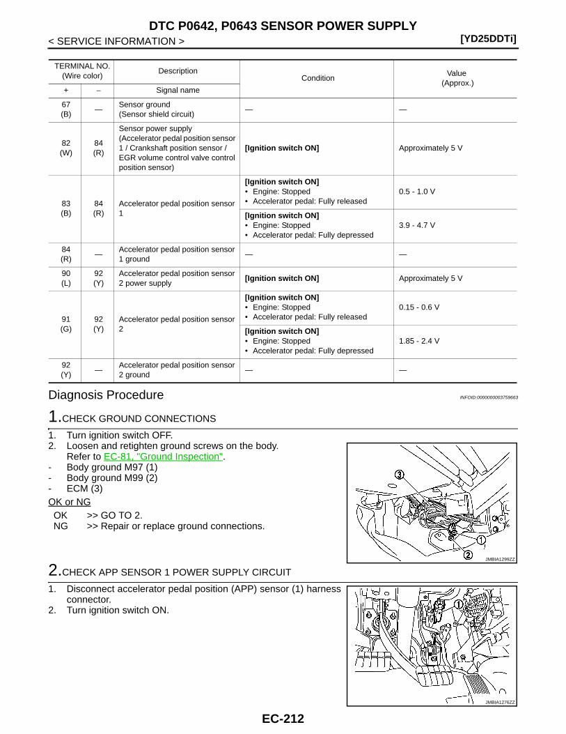
[YD25DDTi]DTC P0642, P0643 SENSOR POWER SUPPLY
< SERVICE INFORMATION >
Diagnosis Procedure INFOID:0000000003759663
1.CHECK GROUND CONNECTIONS
1. Turn ignition switch OFF.2. Loosen and retighten ground screws on the body.
Refer to EC-81, "Ground Inspection".- Body ground M97 (1)- Body ground M99 (2)- ECM (3)OK or NGOK >> GO TO 2.NG >> Repair or replace ground connections.
2.CHECK APP SENSOR 1 POWER SUPPLY CIRCUIT
1. Disconnect accelerator pedal position (APP) sensor (1) harnessconnector.
2. Turn ignition switch ON.
TERMINAL NO.(Wire color)
DescriptionCondition
Value (Approx.)
+ − Signal name
67(B)
—Sensor ground(Sensor shield circuit)
— —
82(W)
84(R)
Sensor power supply(Accelerator pedal position sensor 1 / Crankshaft position sensor / EGR volume control valve control position sensor)
[Ignition switch ON] Approximately 5 V
83(B)
84(R)
Accelerator pedal position sensor 1
[Ignition switch ON]• Engine: Stopped• Accelerator pedal: Fully released
0.5 - 1.0 V
[Ignition switch ON]• Engine: Stopped• Accelerator pedal: Fully depressed
3.9 - 4.7 V
84(R)
—Accelerator pedal position sensor 1 ground
— —
90(L)
92(Y)
Accelerator pedal position sensor 2 power supply
[Ignition switch ON] Approximately 5 V
91(G)
92(Y)
Accelerator pedal position sensor 2
[Ignition switch ON]• Engine: Stopped• Accelerator pedal: Fully released
0.15 - 0.6 V
[Ignition switch ON]• Engine: Stopped• Accelerator pedal: Fully depressed
1.85 - 2.4 V
92(Y)
—Accelerator pedal position sensor 2 ground
— —
JMBIA1299ZZ
JMBIA1276ZZ
EC-212

DTC P0642, P0643 SENSOR POWER SUPPLY[YD25DDTi]
C
D
E
F
G
H
I
J
K
L
M
A
C
N
P
O
< SERVICE INFORMATION >
E
3. Check voltage between APP sensor terminal 4 and ground withCONSULT-III or tester.
OK or NGOK >> GO TO 5.NG >> GO TO 3.
3.CHECK SENSOR POWER SUPPLY CIRCUITS
Check harness for short to power and short to ground, between the following terminals.
OK or NGOK >> GO TO 4.NG >> Repair short to ground or short to power in harness or connectors.
4.CHECK CRANKSHAFT POSITION SENSOR
Refer to EC-156, "Component Inspection".OK or NGOK >> GO TO 5.NG >> Replace crankshaft position sensor.
5.CHECK APP SENSOR
Refer to EC-123, "Component Inspection".OK or NGOK >> GO TO 6.NG >> Replace accelerator pedal assembly.
6.CHECK INTERMITTENT INCIDENT
Refer to EC-70.OK or NGOK >> GO TO 7.NG >> Repair or replace.
7.REPLACE EGR VOLUME CONTROL VALVE
1. Replace the EGR volume control valve.2. Perform EC-24, "EGR Volume Control Valve Closed Position Learning Value Clear".3. Perform EC-24, "EGR Volume Control Valve Closed Position Learning".
>> INSPECTION END
Voltage: Approximately 5 V
JMBIA1300ZZ
ECM terminal Sensor terminal Reference Wiring Diagram
82
APP sensor terminal 4 EC-211
Crankshaft position sensor terminal 3 EC-153
EGR volume control valve terminal 3 EC-186
EC-213
[YD25DDTi]DTC P0652, P0653 SENSOR POWER SUPPLY
< SERVICE INFORMATION >
DTC P0652, P0653 SENSOR POWER SUPPLY
On Board Diagnosis Logic INFOID:0000000003759664
DTC Confirmation Procedure INFOID:0000000003759665
NOTE:If DTC Confirmation Procedure has been previously conducted, always turn ignition switch OFF and wait atleast 10 seconds before conducting the next test. 1. Turn ignition switch ON.2. Wait at least 5 seconds.3. Check 1st trip DTC.4. If 1st trip DTC is detected, go to EC-216, "Diagnosis Procedure".
DTC No. Trouble diagnosis name DTC detecting condition Possible cause
P06520652
Sensor power supply cir-cuit low
ECM detects a voltage of power source for sensor is excessively low.
• Harness or connectors(APP sensor 2 power supply circuit is shorted.)(Camshaft position sensor circuit is shorted.)(Fuel rail pressure sensor circuit is shorted.)
• Accelerator pedal position sensor(Accelerator pedal position sensor 2)
• Camshaft position sensor• Fuel rail pressure sensor
P06530653
Sensor power supply cir-cuit high
ECM detects a voltage of power source for Sensor is excessively high.
EC-214

DTC P0652, P0653 SENSOR POWER SUPPLY[YD25DDTi]
C
D
E
F
G
H
I
J
K
L
M
A
C
N
P
O
< SERVICE INFORMATION >
E
Wiring Diagram INFOID:0000000003759666
Specification data are reference values and are measured between each terminal and ground.GEC623A
EC-215
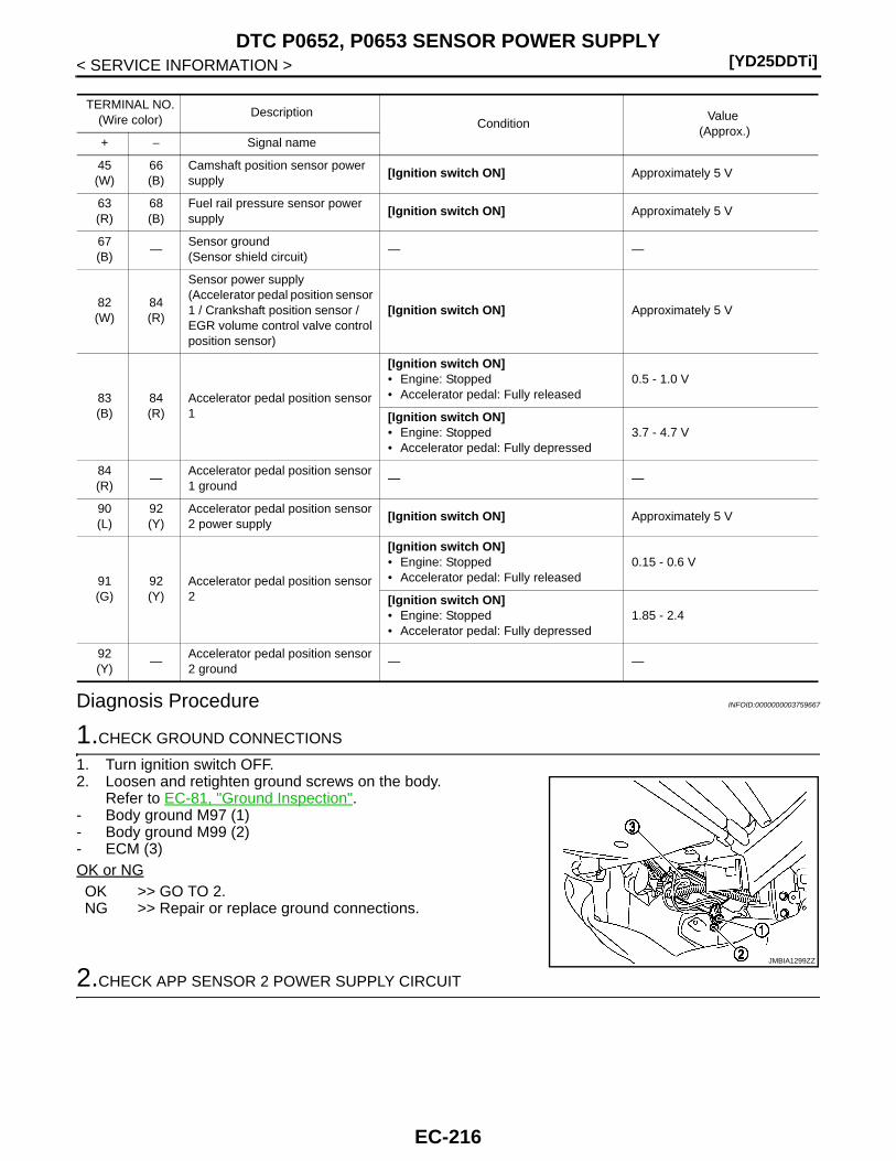
[YD25DDTi]DTC P0652, P0653 SENSOR POWER SUPPLY
< SERVICE INFORMATION >
Diagnosis Procedure INFOID:0000000003759667
1.CHECK GROUND CONNECTIONS
1. Turn ignition switch OFF.2. Loosen and retighten ground screws on the body.
Refer to EC-81, "Ground Inspection".- Body ground M97 (1)- Body ground M99 (2)- ECM (3)OK or NGOK >> GO TO 2.NG >> Repair or replace ground connections.
2.CHECK APP SENSOR 2 POWER SUPPLY CIRCUIT
TERMINAL NO.(Wire color)
DescriptionCondition
Value (Approx.)
+ − Signal name
45(W)
66(B)
Camshaft position sensor power supply
[Ignition switch ON] Approximately 5 V
63(R)
68(B)
Fuel rail pressure sensor power supply
[Ignition switch ON] Approximately 5 V
67(B)
—Sensor ground(Sensor shield circuit)
— —
82(W)
84(R)
Sensor power supply(Accelerator pedal position sensor 1 / Crankshaft position sensor / EGR volume control valve control position sensor)
[Ignition switch ON] Approximately 5 V
83(B)
84(R)
Accelerator pedal position sensor 1
[Ignition switch ON]• Engine: Stopped• Accelerator pedal: Fully released
0.5 - 1.0 V
[Ignition switch ON]• Engine: Stopped• Accelerator pedal: Fully depressed
3.7 - 4.7 V
84(R)
—Accelerator pedal position sensor 1 ground
— —
90(L)
92(Y)
Accelerator pedal position sensor 2 power supply
[Ignition switch ON] Approximately 5 V
91(G)
92(Y)
Accelerator pedal position sensor 2
[Ignition switch ON]• Engine: Stopped• Accelerator pedal: Fully released
0.15 - 0.6 V
[Ignition switch ON]• Engine: Stopped• Accelerator pedal: Fully depressed
1.85 - 2.4
92(Y)
—Accelerator pedal position sensor 2 ground
— —
JMBIA1299ZZ
EC-216
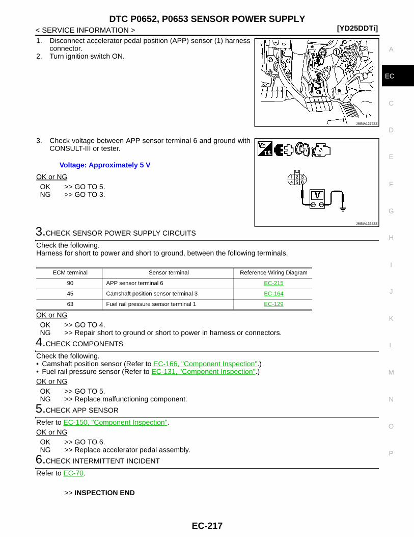
DTC P0652, P0653 SENSOR POWER SUPPLY[YD25DDTi]
C
D
E
F
G
H
I
J
K
L
M
A
C
N
P
O
< SERVICE INFORMATION >
E
1. Disconnect accelerator pedal position (APP) sensor (1) harnessconnector.
2. Turn ignition switch ON.
3. Check voltage between APP sensor terminal 6 and ground withCONSULT-III or tester.
OK or NGOK >> GO TO 5.NG >> GO TO 3.
3.CHECK SENSOR POWER SUPPLY CIRCUITS
Check the following.Harness for short to power and short to ground, between the following terminals.
OK or NGOK >> GO TO 4.NG >> Repair short to ground or short to power in harness or connectors.
4.CHECK COMPONENTS
Check the following.• Camshaft position sensor (Refer to EC-166, "Component Inspection".)• Fuel rail pressure sensor (Refer to EC-131, "Component Inspection".)OK or NGOK >> GO TO 5.NG >> Replace malfunctioning component.
5.CHECK APP SENSOR
Refer to EC-150, "Component Inspection".OK or NGOK >> GO TO 6.NG >> Replace accelerator pedal assembly.
6.CHECK INTERMITTENT INCIDENT
Refer to EC-70.
>> INSPECTION END
JMBIA1276ZZ
Voltage: Approximately 5 V
JMBIA1368ZZ
ECM terminal Sensor terminal Reference Wiring Diagram
90 APP sensor terminal 6 EC-215
45 Camshaft position sensor terminal 3 EC-164
63 Fuel rail pressure sensor terminal 1 EC-129
EC-217
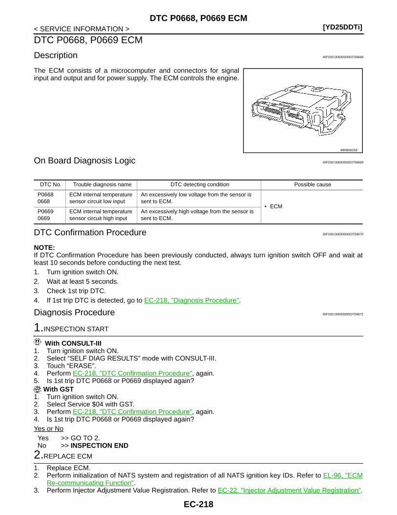
[YD25DDTi]DTC P0668, P0669 ECM
< SERVICE INFORMATION >
DTC P0668, P0669 ECM
Description INFOID:0000000003759668
The ECM consists of a microcomputer and connectors for signalinput and output and for power supply. The ECM controls the engine.
On Board Diagnosis Logic INFOID:0000000003759669
DTC Confirmation Procedure INFOID:0000000003759670
NOTE:If DTC Confirmation Procedure has been previously conducted, always turn ignition switch OFF and wait atleast 10 seconds before conducting the next test. 1. Turn ignition switch ON.2. Wait at least 5 seconds.3. Check 1st trip DTC.4. If 1st trip DTC is detected, go to EC-218, "Diagnosis Procedure".
Diagnosis Procedure INFOID:0000000003759671
1.INSPECTION START
With CONSULT-III1. Turn ignition switch ON.2. Select “SELF DIAG RESULTS” mode with CONSULT-III.3. Touch “ERASE”.4. Perform EC-218, "DTC Confirmation Procedure", again.5. Is 1st trip DTC P0668 or P0669 displayed again?
With GST1. Turn ignition switch ON.2. Select Service $04 with GST.3. Perform EC-218, "DTC Confirmation Procedure", again.4. Is 1st trip DTC P0668 or P0669 displayed again?Yes or NoYes >> GO TO 2.No >> INSPECTION END
2.REPLACE ECM
1. Replace ECM.2. Perform initialization of NATS system and registration of all NATS ignition key IDs. Refer to EL-96, "ECM
Re-communicating Function".3. Perform Injector Adjustment Value Registration. Refer to EC-22, "Injector Adjustment Value Registration".
MBIB0625E
DTC No. Trouble diagnosis name DTC detecting condition Possible cause
P06680668
ECM internal temperature sensor circuit low input
An excessively low voltage from the sensor is sent to ECM.
• ECMP06690669
ECM internal temperature sensor circuit high input
An excessively high voltage from the sensor is sent to ECM.
EC-218
DTC P0668, P0669 ECM[YD25DDTi]
C
D
E
F
G
H
I
J
K
L
M
A
C
N
P
O
< SERVICE INFORMATION >
E
4. Perform Fuel Pump Learning Value Clearing. Refer to EC-23, "Fuel Pump Learning Value Clearing".5. Perform EGR Volume Control Valve Closed Position Learning Value Clear. Refer to EC-24, "EGR Volume
Control Valve Closed Position Learning Value Clear".6. Perform EGR Volume Control Valve Closed Position Learning. Refer to EC-24, "EGR Volume Control
Valve Closed Position Learning".
>> INSPECTION END
EC-219
[YD25DDTi]DTC P0686 ECM RELAY
< SERVICE INFORMATION >
DTC P0686 ECM RELAY
On Board Diagnosis Logic INFOID:0000000003759672
This self-diagnosis has the one trip detection logic.The MI will not light up for this self-diagnosis.
DTC Confirmation Procedure INFOID:0000000003759673
NOTE:If DTC Confirmation Procedure has been previously conducted, always turn ignition switch OFF and wait atleast 10 seconds before conducting the next test. 1. Turn ignition switch ON and then turn OFF.2. Wait at least 30 seconds.3. Turn ignition switch ON.4. Check DTC.5. If DTC is detected, go to EC-224, "Diagnosis Procedure".
DTC No. Trouble diagnosis name DTC detecting condition Possible cause
P06860686
ECM relay circuitECM detects ECM relay is stuck closed even if ig-nition switch OFF.
• Harness or connectors(The ECM relay circuit is shorted.)
• ECM relay
EC-220
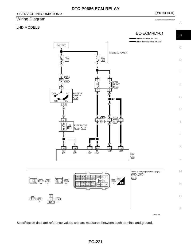
DTC P0686 ECM RELAY[YD25DDTi]
C
D
E
F
G
H
I
J
K
L
M
A
C
N
P
O
< SERVICE INFORMATION >
E
Wiring Diagram INFOID:0000000003759674
LHD MODELS
Specification data are reference values and are measured between each terminal and ground.
GEC624A
EC-221
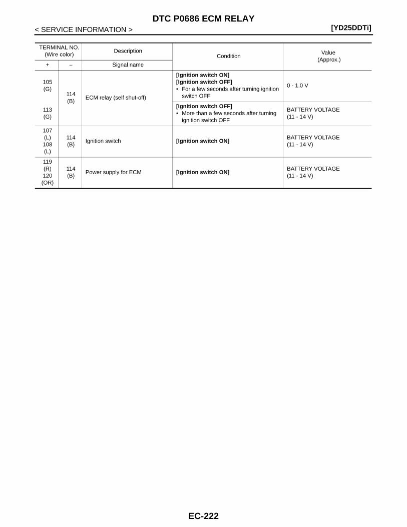
[YD25DDTi]DTC P0686 ECM RELAY
< SERVICE INFORMATION >
TERMINAL NO.(Wire color)
DescriptionCondition
Value (Approx.)
+ − Signal name
105(G)
114(B)
ECM relay (self shut-off)
[Ignition switch ON][Ignition switch OFF]• For a few seconds after turning ignition
switch OFF
0 - 1.0 V
113(G)
[Ignition switch OFF]• More than a few seconds after turning
ignition switch OFF
BATTERY VOLTAGE(11 - 14 V)
107(L)108(L)
114(B)
Ignition switch [Ignition switch ON]BATTERY VOLTAGE(11 - 14 V)
119(R)120(OR)
114(B)
Power supply for ECM [Ignition switch ON]BATTERY VOLTAGE(11 - 14 V)
EC-222
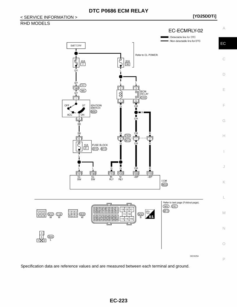
DTC P0686 ECM RELAY[YD25DDTi]
C
D
E
F
G
H
I
J
K
L
M
A
C
N
P
O
< SERVICE INFORMATION >
E
RHD MODELS
Specification data are reference values and are measured between each terminal and ground.
GEC625A
EC-223

[YD25DDTi]DTC P0686 ECM RELAY
< SERVICE INFORMATION >
Diagnosis Procedure INFOID:0000000003759675
1.CHECK ECM RELAY INPUT SIGNAL CIRCUIT
1. Turn ignition switch ON and then OFF.2. Check voltage between ECM harness connector terminals as follows.
OK or NGOK >> GO TO 10.NG >> GO TO 2.
2.CHECK ECM RELAY SIGNAL CIRCUIT FOR SHORT TO GROUND
Check the voltage between ECM relay harness connector and ground.
OK or NGOK >> GO TO 4.NG >> GO TO 3.
3.DETECT MALFUNCTIONING PART
TERMINAL NO.(Wire color)
DescriptionCondition
Value (Approx.)
+ − Signal name
105(G)
114(B)
ECM relay (self shut-off)
[Ignition switch ON][Ignition switch OFF]• For a few seconds after turning ignition
switch OFF
0 - 1.0 V
113(G)
[Ignition switch OFF]• More than a few seconds after turning
ignition switch OFF
BATTERY VOLTAGE(11 - 14 V)
107(L)108(L)
114(B)
Ignition switch [Ignition switch ON]BATTERY VOLTAGE(11 - 14 V)
119(R)120(OR)
114(B)
Power supply for ECM [Ignition switch ON]BATTERY VOLTAGE(11 - 14 V)
ECM
Voltage+ –
Connector Terminal Connector Terminal
M33
119M32
1
After turning ignition switch OFF, battery voltage will exist for a few seconds, then drop approximately 0 V.
2
3
M33 114
120M32
1
2
3
M33 114
ECM relayGround Voltage
Connector Terminal
E552
Ground Battery voltage3
EC-224
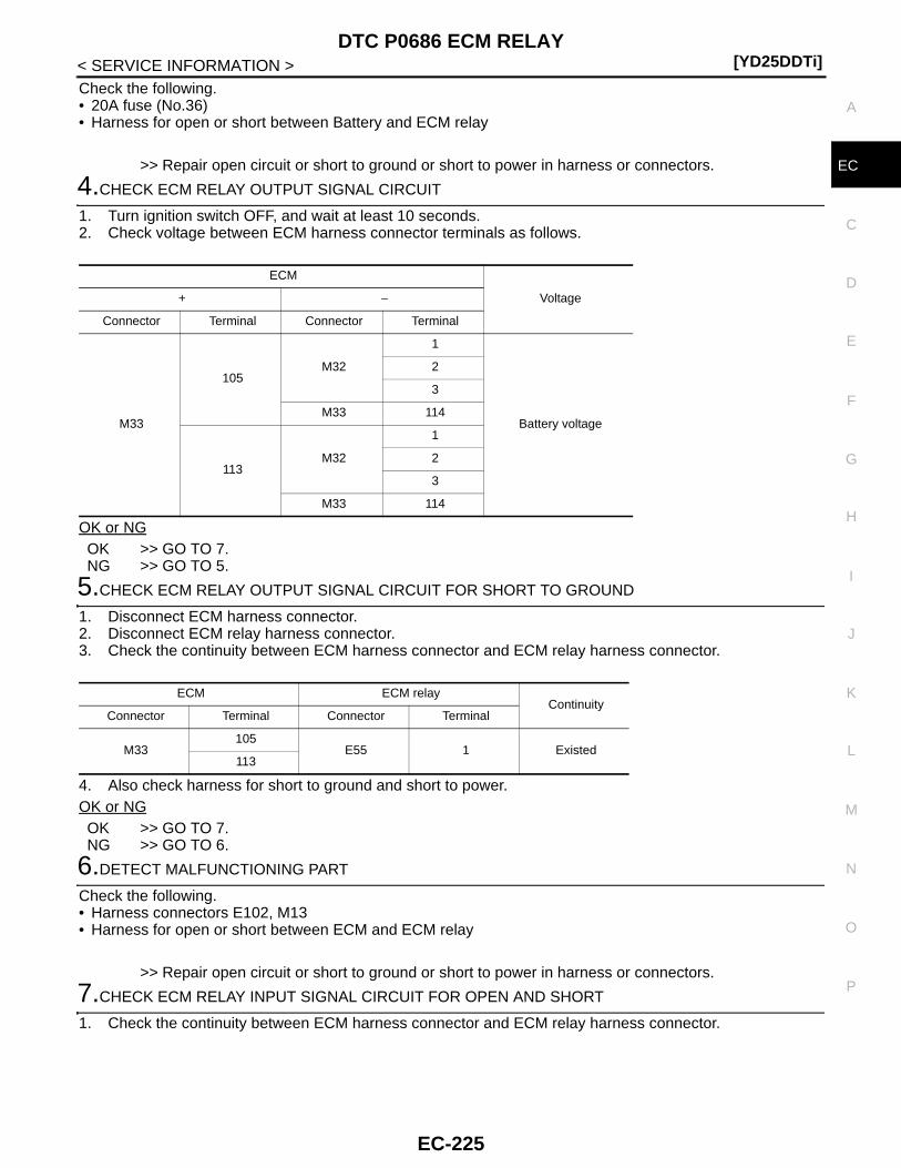
DTC P0686 ECM RELAY[YD25DDTi]
C
D
E
F
G
H
I
J
K
L
M
A
C
N
P
O
< SERVICE INFORMATION >
E
Check the following.• 20A fuse (No.36)• Harness for open or short between Battery and ECM relay
>> Repair open circuit or short to ground or short to power in harness or connectors.
4.CHECK ECM RELAY OUTPUT SIGNAL CIRCUIT
1. Turn ignition switch OFF, and wait at least 10 seconds.2. Check voltage between ECM harness connector terminals as follows.
OK or NGOK >> GO TO 7.NG >> GO TO 5.
5.CHECK ECM RELAY OUTPUT SIGNAL CIRCUIT FOR SHORT TO GROUND
1. Disconnect ECM harness connector.2. Disconnect ECM relay harness connector.3. Check the continuity between ECM harness connector and ECM relay harness connector.
4. Also check harness for short to ground and short to power.OK or NGOK >> GO TO 7.NG >> GO TO 6.
6.DETECT MALFUNCTIONING PART
Check the following.• Harness connectors E102, M13• Harness for open or short between ECM and ECM relay
>> Repair open circuit or short to ground or short to power in harness or connectors.
7.CHECK ECM RELAY INPUT SIGNAL CIRCUIT FOR OPEN AND SHORT
1. Check the continuity between ECM harness connector and ECM relay harness connector.
ECM
Voltage+ −
Connector Terminal Connector Terminal
M33
105M32
1
Battery voltage
2
3
M33 114
113M32
1
2
3
M33 114
ECM ECM relayContinuity
Connector Terminal Connector Terminal
M33105
E55 1 Existed113
EC-225
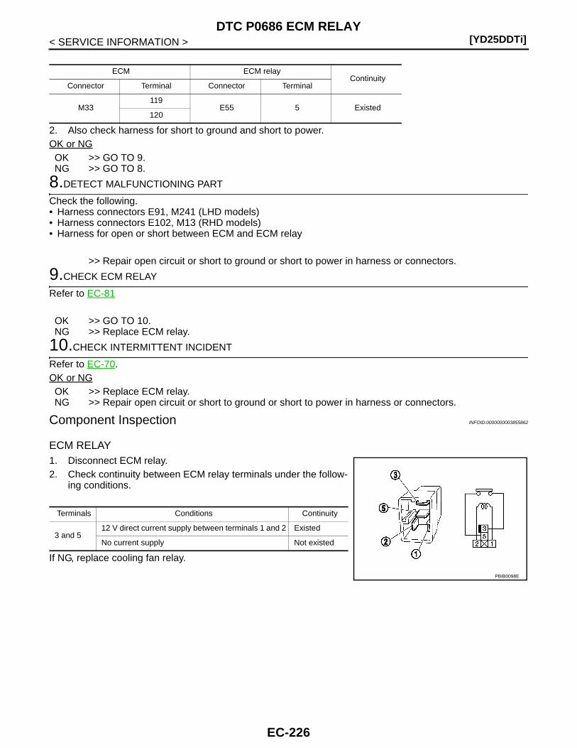
[YD25DDTi]DTC P0686 ECM RELAY
< SERVICE INFORMATION >
2. Also check harness for short to ground and short to power.OK or NGOK >> GO TO 9.NG >> GO TO 8.
8.DETECT MALFUNCTIONING PART
Check the following.• Harness connectors E91, M241 (LHD models)• Harness connectors E102, M13 (RHD models)• Harness for open or short between ECM and ECM relay
>> Repair open circuit or short to ground or short to power in harness or connectors.
9.CHECK ECM RELAY
Refer to EC-81
OK >> GO TO 10.NG >> Replace ECM relay.
10.CHECK INTERMITTENT INCIDENT
Refer to EC-70.OK or NGOK >> Replace ECM relay.NG >> Repair open circuit or short to ground or short to power in harness or connectors.
Component Inspection INFOID:0000000003855862
ECM RELAY1. Disconnect ECM relay.2. Check continuity between ECM relay terminals under the follow-
ing conditions.
If NG, replace cooling fan relay.
ECM ECM relayContinuity
Connector Terminal Connector Terminal
M33119
E55 5 Existed120
Terminals Conditions Continuity
3 and 512 V direct current supply between terminals 1 and 2 Existed
No current supply Not existed
PBIB0098E
EC-226
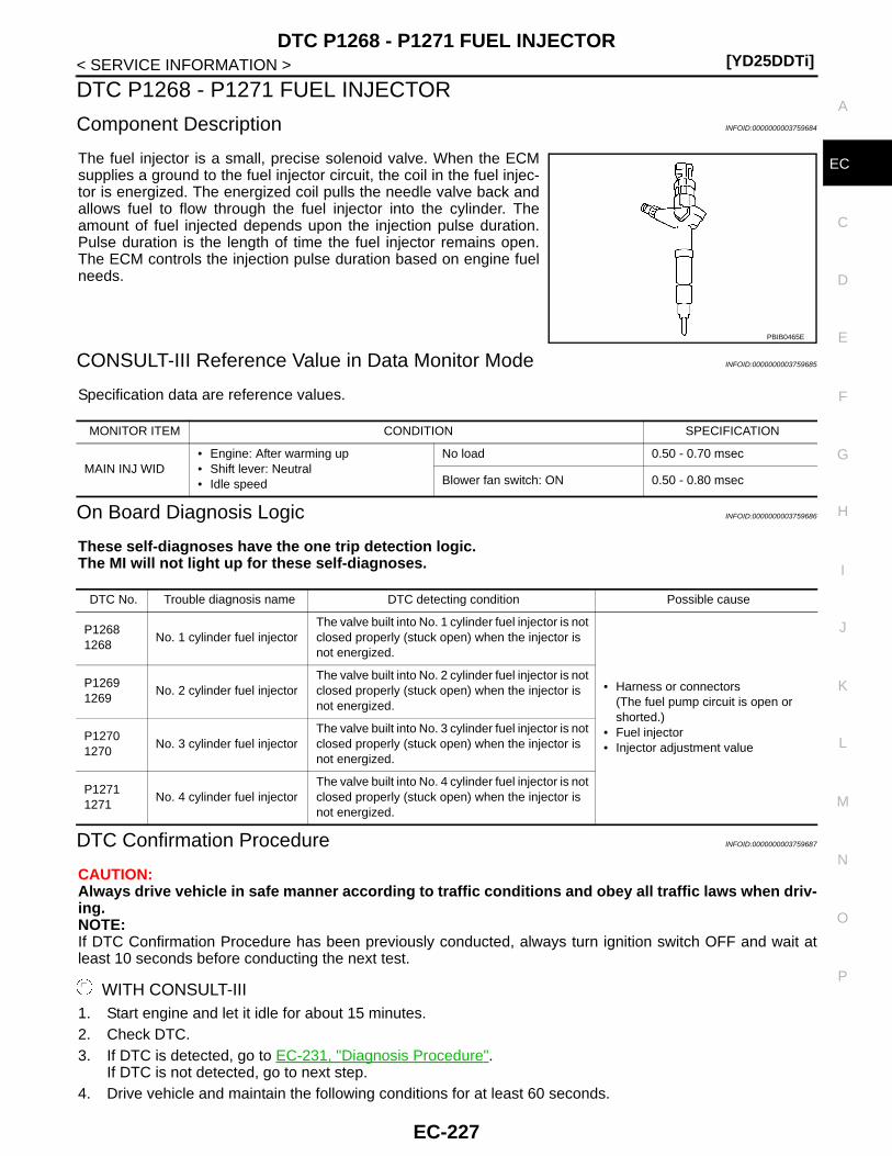
DTC P1268 - P1271 FUEL INJECTOR[YD25DDTi]
C
D
E
F
G
H
I
J
K
L
M
A
C
N
P
O
< SERVICE INFORMATION >
E
DTC P1268 - P1271 FUEL INJECTOR
Component Description INFOID:0000000003759684
The fuel injector is a small, precise solenoid valve. When the ECMsupplies a ground to the fuel injector circuit, the coil in the fuel injec-tor is energized. The energized coil pulls the needle valve back andallows fuel to flow through the fuel injector into the cylinder. Theamount of fuel injected depends upon the injection pulse duration.Pulse duration is the length of time the fuel injector remains open.The ECM controls the injection pulse duration based on engine fuelneeds.
CONSULT-III Reference Value in Data Monitor Mode INFOID:0000000003759685
Specification data are reference values.
On Board Diagnosis Logic INFOID:0000000003759686
These self-diagnoses have the one trip detection logic.The MI will not light up for these self-diagnoses.
DTC Confirmation Procedure INFOID:0000000003759687
CAUTION:Always drive vehicle in safe manner according to traffic conditions and obey all traffic laws when driv-ing.NOTE:If DTC Confirmation Procedure has been previously conducted, always turn ignition switch OFF and wait atleast 10 seconds before conducting the next test.
WITH CONSULT-III1. Start engine and let it idle for about 15 minutes.2. Check DTC.3. If DTC is detected, go to EC-231, "Diagnosis Procedure".
If DTC is not detected, go to next step.4. Drive vehicle and maintain the following conditions for at least 60 seconds.
PBIB0465E
MONITOR ITEM CONDITION SPECIFICATION
MAIN INJ WID• Engine: After warming up• Shift lever: Neutral• Idle speed
No load 0.50 - 0.70 msec
Blower fan switch: ON 0.50 - 0.80 msec
DTC No. Trouble diagnosis name DTC detecting condition Possible cause
P12681268
No. 1 cylinder fuel injectorThe valve built into No. 1 cylinder fuel injector is not closed properly (stuck open) when the injector is not energized.
• Harness or connectors(The fuel pump circuit is open or shorted.)
• Fuel injector• Injector adjustment value
P12691269
No. 2 cylinder fuel injectorThe valve built into No. 2 cylinder fuel injector is not closed properly (stuck open) when the injector is not energized.
P12701270
No. 3 cylinder fuel injectorThe valve built into No. 3 cylinder fuel injector is not closed properly (stuck open) when the injector is not energized.
P12711271
No. 4 cylinder fuel injectorThe valve built into No. 4 cylinder fuel injector is not closed properly (stuck open) when the injector is not energized.
EC-227

[YD25DDTi]DTC P1268 - P1271 FUEL INJECTOR
< SERVICE INFORMATION >
5. Check DTC.6. If DTC is detected, go to EC-231, "Diagnosis Procedure".
WITH GSTFollow the procedure “WITH CONSULT-III” above.
CKPS·RPM 700 - 2,000 rpm (A constant rotation is maintained)
COOLAN TEMP/S Less than 75°C (167°F)
Shift lever Suitable position
Accelerator pedal Hold the accelerator pedal as steady as possible.
EC-228
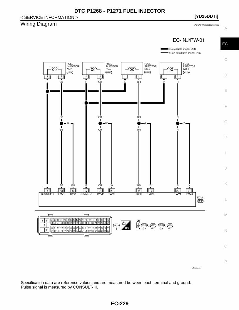
DTC P1268 - P1271 FUEL INJECTOR[YD25DDTi]
C
D
E
F
G
H
I
J
K
L
M
A
C
N
P
O
< SERVICE INFORMATION >
E
Wiring Diagram INFOID:0000000003759688
Specification data are reference values and are measured between each terminal and ground.Pulse signal is measured by CONSULT-III.
GEC627A
EC-229
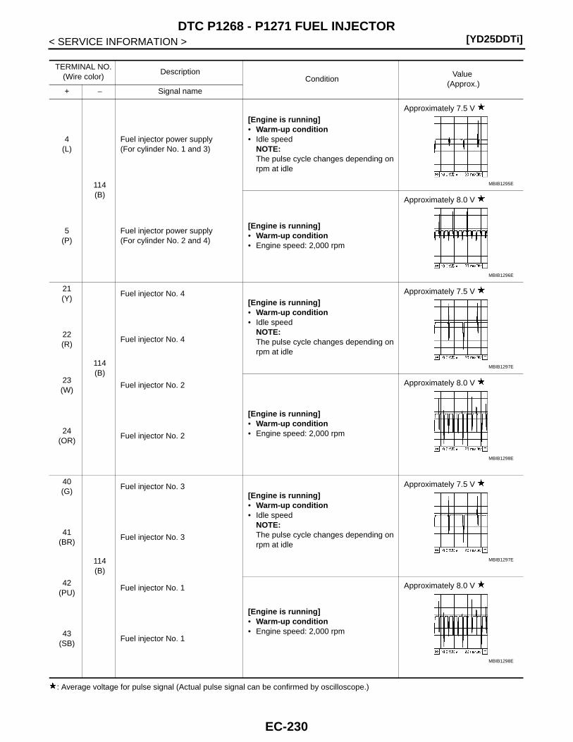
[YD25DDTi]DTC P1268 - P1271 FUEL INJECTOR
< SERVICE INFORMATION >
: Average voltage for pulse signal (Actual pulse signal can be confirmed by oscilloscope.)
TERMINAL NO.(Wire color)
DescriptionCondition
Value (Approx.)
+ − Signal name
4(L)
114(B)
Fuel injector power supply(For cylinder No. 1 and 3)
[Engine is running]• Warm-up condition• Idle speed
NOTE:The pulse cycle changes depending on rpm at idle
Approximately 7.5 V
5(P)
Fuel injector power supply(For cylinder No. 2 and 4)
[Engine is running]• Warm-up condition• Engine speed: 2,000 rpm
Approximately 8.0 V
21(Y)
114(B)
Fuel injector No. 4[Engine is running]• Warm-up condition• Idle speed
NOTE:The pulse cycle changes depending on rpm at idle
Approximately 7.5 V
22(R)
Fuel injector No. 4
23(W)
Fuel injector No. 2
[Engine is running]• Warm-up condition• Engine speed: 2,000 rpm
Approximately 8.0 V
24(OR)
Fuel injector No. 2
40(G)
114(B)
Fuel injector No. 3[Engine is running]• Warm-up condition• Idle speed
NOTE:The pulse cycle changes depending on rpm at idle
Approximately 7.5 V
41(BR)
Fuel injector No. 3
42(PU)
Fuel injector No. 1
[Engine is running]• Warm-up condition• Engine speed: 2,000 rpm
Approximately 8.0 V
43(SB)
Fuel injector No. 1
MBIB1295E
MBIB1296E
MBIB1297E
MBIB1298E
MBIB1297E
MBIB1298E
EC-230

DTC P1268 - P1271 FUEL INJECTOR[YD25DDTi]
C
D
E
F
G
H
I
J
K
L
M
A
C
N
P
O
< SERVICE INFORMATION >
E
Diagnosis Procedure INFOID:0000000003759690
1.CHECK INJECTOR ADJUSTMENT VALUE
1. Turn ignition switch ON.2. Select “ENTER INJCTR CALIB DATA” in “WORK SUPPORT” mode with CONSULT-III.3. Check injector adjustment values displayed on CONSULT-III screen.
OK or NGOK >> GO TO 2.NG >> Perform Injector Adjustment Value Registration. Refer to EC-22, "Injector Adjustment Value Reg-
istration".
2.CHECK FUEL INJECTOR POWER SUPPLY CIRCUIT FOR OPEN AND SHORT
1. Turn ignition switch OFF.2. Disconnect fuel injector (1) harness connector.
3. Disconnect ECM harness connector.4. Check harness continuity between the following terminals corre-
sponding to the malfunctioning cylinder. Refer to Wiring Dia-gram.
5. Also check harness for short to ground and short to power.OK or NGOK >> GO TO 3.NG >> Repair open circuit or short to ground or short to power in harness or connectors.
3.CHECK ECM OUTPUT SIGNAL CIRCUIT FOR OPEN AND SHORT
1. Check harness continuity between the following terminals corresponding to the malfunctioning cylinder.Refer to Wiring Diagram.
2. Also check harness for short to ground and short to power.OK or NG
The value displayed on CONSULT-III screen should be same as injector adjustment value printed on each fuel injector.
: Vehicle front
DTCTerminal
CylinderECM Fuel injector
P1268 4 1 No.1
P1269 5 1 No.2
P1270 4 1 No.3
P1271 5 1 No.4
Continuity should exist.
JMBIA1282ZZ
DTCTerminal
CylinderECM Fuel injector
P1268 42, 43 2 No.1
P1269 23, 24 2 No.2
P1270 40, 41 2 No.3
P1271 21, 22 2 No.4
Continuity should exist.
EC-231

[YD25DDTi]DTC P1268 - P1271 FUEL INJECTOR
< SERVICE INFORMATION >OK >> GO TO 4.NG >> Repair open circuit or short to ground or short to power in harness or connectors.
4.CHECK FUEL INJECTOR-I
Refer to EC-232, "Component Inspection".OK or NGOK >> GO TO 5.NG >> GO TO 6.
5.CHECK FUEL INJECTOR-II
With CONSULT-III1. Remove two fuel injectors.
NOTE:One is from malfunctioning cylinder and the other is from any cylinder other than the malfunctioning cylin-der.
2. Swap the two fuel injectors to the other cylinder.3. Reconnect ECM harness connector and fuel injector harness connector.4. Turn ignition switch ON.5. Perform Injector Adjustment Value Registration. Refer to EC-22, "Injector Adjustment Value Registration".6. Select “SELF DIAG RESULTS” mode with CONSULT-III.7. Touch “ERASE”.8. Perform EC-227, "DTC Confirmation Procedure".9. Is DTC displayed for the other cylinder?
With GST1. Remove two fuel injectors.
NOTE:One is from malfunctioning cylinder and the other is from any cylinder other than the malfunctioning cylin-der.
2. Swap the two fuel injectors to the other cylinder.3. Reconnect ECM harness connector and fuel injector harness connector.4. Turn ignition switch ON.5. Perform Injector Adjustment Value Registration. Refer to EC-22, "Injector Adjustment Value Registration".6. Select Service $04 with GST.7. Perform EC-227, "DTC Confirmation Procedure".8. Is DTC displayed for the other cylinder?Yes or NoYes >> GO TO 6.No >> GO TO 7.
6.REPLACE FUEL INJECTOR
1. Replace fuel injector of malfunctioning cylinder.2. Perform Injector Adjustment Value Registration. Refer to EC-22, "Injector Adjustment Value Registration".
>> INSPECTION END
7.CHECK INTERMITTENT INCIDENT
Refer to EC-70.
>> INSPECTION END
Component Inspection INFOID:0000000003759691
FUEL INJECTOR1. Disconnect fuel injector harness connector.
EC-232
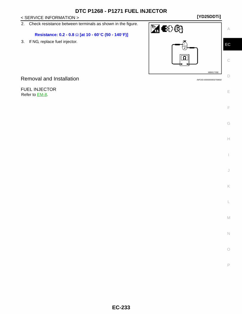
DTC P1268 - P1271 FUEL INJECTOR[YD25DDTi]
C
D
E
F
G
H
I
J
K
L
M
A
C
N
P
O
< SERVICE INFORMATION >
E
2. Check resistance between terminals as shown in the figure.
3. If NG, replace fuel injector.
Removal and Installation INFOID:0000000003759692
FUEL INJECTORRefer to EM-8.
Resistance: 0.2 - 0.8 Ω [at 10 - 60°C (50 - 140°F)]
MBIB1735E
EC-233
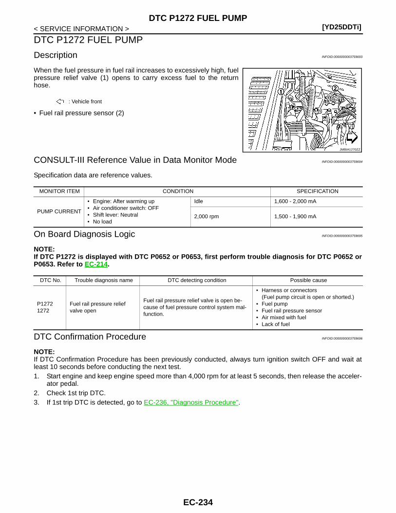
[YD25DDTi]DTC P1272 FUEL PUMP
< SERVICE INFORMATION >
DTC P1272 FUEL PUMP
Description INFOID:0000000003759693
When the fuel pressure in fuel rail increases to excessively high, fuelpressure relief valve (1) opens to carry excess fuel to the returnhose.
• Fuel rail pressure sensor (2)
CONSULT-III Reference Value in Data Monitor Mode INFOID:0000000003759694
Specification data are reference values.
On Board Diagnosis Logic INFOID:0000000003759695
NOTE:If DTC P1272 is displayed with DTC P0652 or P0653, first perform trouble diagnosis for DTC P0652 orP0653. Refer to EC-214.
DTC Confirmation Procedure INFOID:0000000003759696
NOTE:If DTC Confirmation Procedure has been previously conducted, always turn ignition switch OFF and wait atleast 10 seconds before conducting the next test. 1. Start engine and keep engine speed more than 4,000 rpm for at least 5 seconds, then release the acceler-
ator pedal.2. Check 1st trip DTC.3. If 1st trip DTC is detected, go to EC-236, "Diagnosis Procedure".
: Vehicle front
JMBIA1270ZZ
MONITOR ITEM CONDITION SPECIFICATION
PUMP CURRENT
• Engine: After warming up• Air conditioner switch: OFF• Shift lever: Neutral• No load
Idle 1,600 - 2,000 mA
2,000 rpm 1,500 - 1,900 mA
DTC No. Trouble diagnosis name DTC detecting condition Possible cause
P12721272
Fuel rail pressure relief valve open
Fuel rail pressure relief valve is open be-cause of fuel pressure control system mal-function.
• Harness or connectors(Fuel pump circuit is open or shorted.)
• Fuel pump• Fuel rail pressure sensor• Air mixed with fuel• Lack of fuel
EC-234

DTC P1272 FUEL PUMP[YD25DDTi]
C
D
E
F
G
H
I
J
K
L
M
A
C
N
P
O
< SERVICE INFORMATION >
E
Wiring Diagram INFOID:0000000003759697
Specification data are reference values and are measured between each terminal and ground.Pulse signal is measured by CONSULT-III.
GEC621A
EC-235
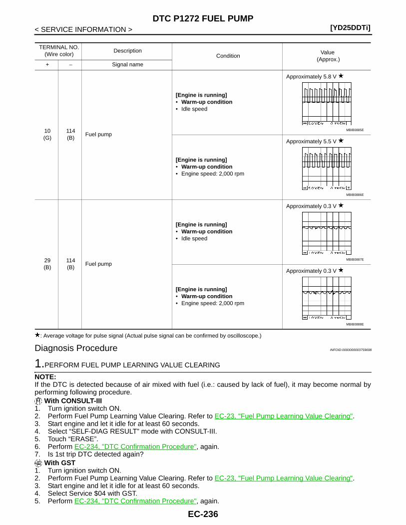
[YD25DDTi]DTC P1272 FUEL PUMP
< SERVICE INFORMATION >
: Average voltage for pulse signal (Actual pulse signal can be confirmed by oscilloscope.)
Diagnosis Procedure INFOID:0000000003759698
1.PERFORM FUEL PUMP LEARNING VALUE CLEARING
NOTE:If the DTC is detected because of air mixed with fuel (i.e.: caused by lack of fuel), it may become normal byperforming following procedure.
With CONSULT-III1. Turn ignition switch ON.2. Perform Fuel Pump Learning Value Clearing. Refer to EC-23, "Fuel Pump Learning Value Clearing".3. Start engine and let it idle for at least 60 seconds.4. Select “SELF-DIAG RESULT” mode with CONSULT-III.5. Touch “ERASE”.6. Perform EC-234, "DTC Confirmation Procedure", again.7. Is 1st trip DTC detected again?
With GST1. Turn ignition switch ON.2. Perform Fuel Pump Learning Value Clearing. Refer to EC-23, "Fuel Pump Learning Value Clearing".3. Start engine and let it idle for at least 60 seconds.4. Select Service $04 with GST.5. Perform EC-234, "DTC Confirmation Procedure", again.
TERMINAL NO.(Wire color)
DescriptionCondition
Value (Approx.)
+ − Signal name
10(G)
114(B)
Fuel pump
[Engine is running]• Warm-up condition• Idle speed
Approximately 5.8 V
[Engine is running]• Warm-up condition• Engine speed: 2,000 rpm
Approximately 5.5 V
29(B)
114(B)
Fuel pump
[Engine is running]• Warm-up condition• Idle speed
Approximately 0.3 V
[Engine is running]• Warm-up condition• Engine speed: 2,000 rpm
Approximately 0.3 V
MBIB0885E
MBIB0886E
MBIB0887E
MBIB0888E
EC-236
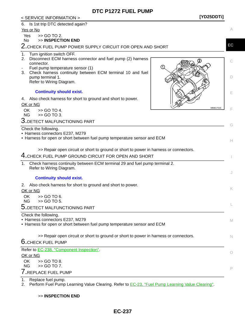
DTC P1272 FUEL PUMP[YD25DDTi]
C
D
E
F
G
H
I
J
K
L
M
A
C
N
P
O
< SERVICE INFORMATION >
E
6. Is 1st trip DTC detected again?Yes or NoYes >> GO TO 2.No >> INSPECTION END
2.CHECK FUEL PUMP POWER SUPPLY CIRCUIT FOR OPEN AND SHORT
1. Turn ignition switch OFF.2. Disconnect ECM harness connector and fuel pump (2) harness
connector.- Fuel pump temperature sensor (1)3. Check harness continuity between ECM terminal 10 and fuel
pump terminal 1.Refer to Wiring Diagram.
4. Also check harness for short to ground and short to power.OK or NGOK >> GO TO 4.NG >> GO TO 3.
3.DETECT MALFUNCTIONING PART
Check the following.• Harness connectors E237, M279• Harness for open or short between fuel pump temperature sensor and ECM
>> Repair open circuit or short to ground or short to power in harness or connectors.
4.CHECK FUEL PUMP GROUND CIRCUIT FOR OPEN AND SHORT
1. Check harness continuity between ECM terminal 29 and fuel pump terminal 2. Refer to Wiring Diagram.
2. Also check harness for short to ground and short to power.OK or NGOK >> GO TO 6.NG >> GO TO 5.
5.DETECT MALFUNCTIONING PART
Check the following.• Harness connectors E237, M279• Harness for open or short between fuel pump temperature sensor and ECM
>> Repair open circuit or short to ground or short to power in harness or connectors.
6.CHECK FUEL PUMP
Refer to EC-238, "Component Inspection".OK or NGOK >> GO TO 8.NG >> GO TO 7.
7.REPLACE FUEL PUMP
1. Replace fuel pump.2. Perform Fuel Pump Learning Value Clearing. Refer to EC-23, "Fuel Pump Learning Value Clearing".
>> INSPECTION END
Continuity should exist.
MBIB1751E
Continuity should exist.
EC-237

[YD25DDTi]DTC P1272 FUEL PUMP
< SERVICE INFORMATION >
8.CHECK FUEL RAIL PRESSURE SENSOR
Refer to EC-131, "Component Inspection".OK or NGOK >> GO TO 9.NG >> Replace fuel rail.
9.CHECK INTERMITTENT INCIDENT
Refer to EC-70.
>> INSPECTION END
Component Inspection INFOID:0000000003759699
FUEL PUMP1. Disconnect fuel pump harness connector.2. Check resistance between fuel pump terminals 1 and 2.
3. If NG, replace fuel pump.
Removal and Installation INFOID:0000000003759700
FUEL RAILRefer to EM-8.
FUEL PUMPRefer to EC-24.
Resistance: 1.5 - 3.0 Ω [at 10 - 60°C (50 - 140°F)]
JMBIA1445ZZ
EC-238

DTC P1273 FUEL PUMP[YD25DDTi]
C
D
E
F
G
H
I
J
K
L
M
A
C
N
P
O
< SERVICE INFORMATION >
E
DTC P1273 FUEL PUMP
Description INFOID:0000000003759701
To control the amount of the fuel inhalation of the fuel pump, a plunger is built into the fuel pump. When theamount of the fuel inhalation of fuel pump increases, the fuel raises the fuel exhalation pressure. As a result,the fuel injection pressure is raised. When the load of the engine increases, the ECM sends a signal to the fuelpump to raise the injection pressure.
CONSULT-III Reference Value in Data Monitor Mode INFOID:0000000003759702
Specification data are reference values.
On Board Diagnosis Logic INFOID:0000000003759703
NOTE:• If DTC P1273 is displayed with DTC P0652 or P0653, first perform trouble diagnosis for DTC P0652 or
P0653. Refer to EC-214.
DTC Confirmation Procedure INFOID:0000000003759704
NOTE:If DTC Confirmation Procedure has been previously conducted, always turn ignition switch OFF and wait atleast 10 seconds before conducting the next test. 1. Start engine and warm it up to normal operating temperature.2. Keep engine speed more than 2,000 rpm for at least 10 seconds.3. Check 1st trip DTC.4. If 1st trip DTC is detected, go to EC-241, "Diagnosis Procedure".
MONITOR ITEM CONDITION SPECIFICATION
PUMP CURRENT
• Engine: After warming up• Air conditioner switch: OFF• Shift lever: Neutral• No load
Idle 1,600 - 2,000 mA
2,000 rpm 1,500 - 1,900 mA
DTC No. Trouble diagnosis name DTC detecting condition Possible cause
P12731273
Fuel pump insufficient flowECM detects the abnormal pulse of fuel pressure.
• Harness or connectors(The fuel pump circuit is open or shorted.)
• Fuel pump• Injector adjustment value• Air mixed with fuel• Lack of fuel
EC-239

[YD25DDTi]DTC P1273 FUEL PUMP
< SERVICE INFORMATION >
Wiring Diagram INFOID:0000000003759705
Specification data are reference values and are measured between each terminal and ground.Pulse signal is measured by CONSULT-III.
GEC621A
EC-240
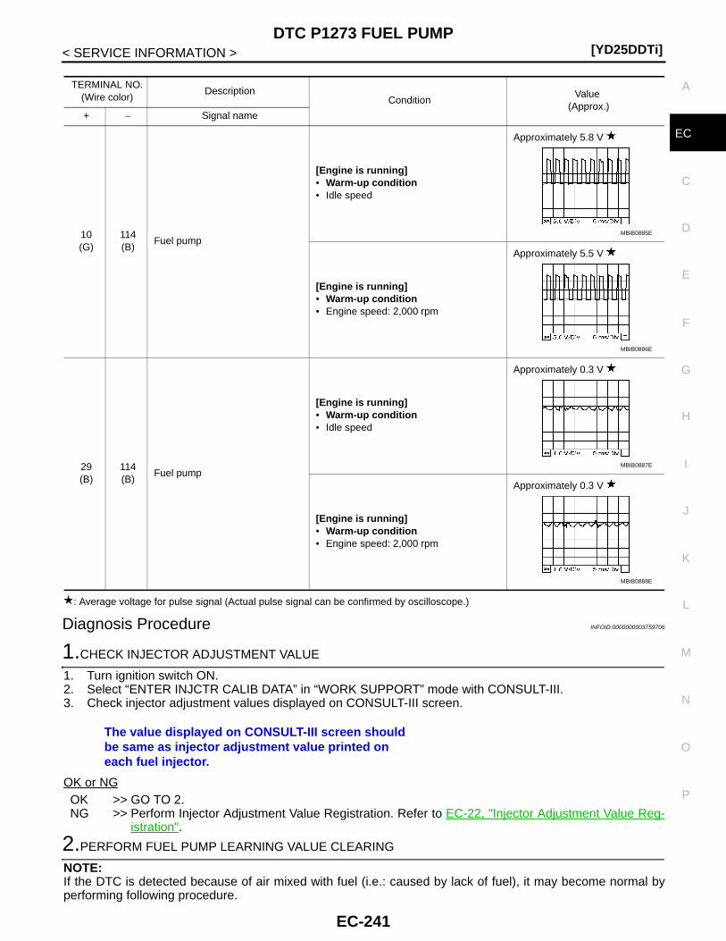
DTC P1273 FUEL PUMP[YD25DDTi]
C
D
E
F
G
H
I
J
K
L
M
A
C
N
P
O
< SERVICE INFORMATION >
E
: Average voltage for pulse signal (Actual pulse signal can be confirmed by oscilloscope.)
Diagnosis Procedure INFOID:0000000003759706
1.CHECK INJECTOR ADJUSTMENT VALUE
1. Turn ignition switch ON.2. Select “ENTER INJCTR CALIB DATA” in “WORK SUPPORT” mode with CONSULT-III.3. Check injector adjustment values displayed on CONSULT-III screen.
OK or NGOK >> GO TO 2.NG >> Perform Injector Adjustment Value Registration. Refer to EC-22, "Injector Adjustment Value Reg-
istration".
2.PERFORM FUEL PUMP LEARNING VALUE CLEARING
NOTE:If the DTC is detected because of air mixed with fuel (i.e.: caused by lack of fuel), it may become normal byperforming following procedure.
TERMINAL NO.(Wire color)
DescriptionCondition
Value (Approx.)
+ − Signal name
10(G)
114(B)
Fuel pump
[Engine is running]• Warm-up condition• Idle speed
Approximately 5.8 V
[Engine is running]• Warm-up condition• Engine speed: 2,000 rpm
Approximately 5.5 V
29(B)
114(B)
Fuel pump
[Engine is running]• Warm-up condition• Idle speed
Approximately 0.3 V
[Engine is running]• Warm-up condition• Engine speed: 2,000 rpm
Approximately 0.3 V
MBIB0885E
MBIB0886E
MBIB0887E
MBIB0888E
The value displayed on CONSULT-III screen should be same as injector adjustment value printed on each fuel injector.
EC-241
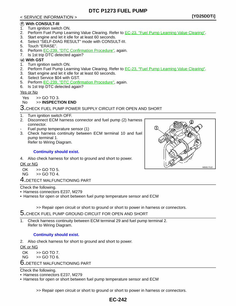
[YD25DDTi]DTC P1273 FUEL PUMP
< SERVICE INFORMATION >
With CONSULT-III1. Turn ignition switch ON.2. Perform Fuel Pump Learning Value Clearing. Refer to EC-23, "Fuel Pump Learning Value Clearing".3. Start engine and let it idle for at least 60 seconds.4. Select “SELF-DIAG RESULT” mode with CONSULT-III.5. Touch “ERASE”.6. Perform EC-239, "DTC Confirmation Procedure", again.7. Is 1st trip DTC detected again?
With GST1. Turn ignition switch ON.2. Perform Fuel Pump Learning Value Clearing. Refer to EC-23, "Fuel Pump Learning Value Clearing".3. Start engine and let it idle for at least 60 seconds.4. Select Service $04 with GST.5. Perform EC-239, "DTC Confirmation Procedure", again.6. Is 1st trip DTC detected again?Yes or NoYes >> GO TO 3.No >> INSPECTION END
3.CHECK FUEL PUMP POWER SUPPLY CIRCUIT FOR OPEN AND SHORT
1. Turn ignition switch OFF.2. Disconnect ECM harness connector and fuel pump (2) harness
connector.- Fuel pump temperature sensor (1)3. Check harness continuity between ECM terminal 10 and fuel
pump terminal 1.Refer to Wiring Diagram.
4. Also check harness for short to ground and short to power.OK or NGOK >> GO TO 5.NG >> GO TO 4.
4.DETECT MALFUNCTIONING PART
Check the following.• Harness connectors E237, M279• Harness for open or short between fuel pump temperature sensor and ECM
>> Repair open circuit or short to ground or short to power in harness or connectors.
5.CHECK FUEL PUMP GROUND CIRCUIT FOR OPEN AND SHORT
1. Check harness continuity between ECM terminal 29 and fuel pump terminal 2. Refer to Wiring Diagram.
2. Also check harness for short to ground and short to power.OK or NGOK >> GO TO 7.NG >> GO TO 6.
6.DETECT MALFUNCTIONING PART
Check the following.• Harness connectors E237, M279• Harness for open or short between fuel pump temperature sensor and ECM
>> Repair open circuit or short to ground or short to power in harness or connectors.
Continuity should exist.
MBIB1751E
Continuity should exist.
EC-242

DTC P1273 FUEL PUMP[YD25DDTi]
C
D
E
F
G
H
I
J
K
L
M
A
C
N
P
O
< SERVICE INFORMATION >
E
7.CHECK FUEL PUMP
Refer to EC-243, "Component Inspection".OK or NGOK >> GO TO 9.NG >> GO TO 8.
8.REPLACE FUEL PUMP
1. Replace fuel pump.2. Perform Fuel Pump Learning Valve Clearing. Refer to EC-23, "Fuel Pump Learning Value Clearing".
>> INSPECTION END
9.CHECK INTERMITTENT INCIDENT
Refer to EC-70.
>> INSPECTION END
Component Inspection INFOID:0000000003759707
FUEL PUMP1. Disconnect fuel pump harness connector.2. Check resistance between fuel pump terminals 1 and 2.
3. If NG, replace fuel pump.
Removal and Installation INFOID:0000000003759708
FUEL PUMPRefer to EC-24.
Resistance: 1.5 - 3.0 Ω [at 10 - 60°C (50 - 140°F)]
JMBIA1445ZZ
EC-243

[YD25DDTi]DTC P1274 FUEL PUMP
< SERVICE INFORMATION >
DTC P1274 FUEL PUMP
Description INFOID:0000000003759709
To control the amount of the fuel inhalation of the fuel pump, a plunger is built into the fuel pump. When theamount of the fuel inhalation of fuel increases, the fuel pump raises the fuel exhalation pressure. As a result,the fuel injection pressure is raised. When the load of the engine increases, the ECM sends a signal to the fuelpump to raise the injection pressure.
CONSULT-III Reference Value in Data Monitor Mode INFOID:0000000003759710
Specification data are reference values.
On Board Diagnosis Logic INFOID:0000000003759711
This self-diagnosis has the one trip detection logic.NOTE:If DTC P1274 is displayed with DTC P0652 or P0653, first perform trouble diagnosis for DTC P0652 orP0653. Refer to EC-214.
DTC Confirmation Procedure INFOID:0000000003759712
NOTE:If DTC Confirmation Procedure has been previously conducted, always turn ignition switch OFF and wait atleast 10 seconds before conducting the next test. 1. Tuning ignition switch ON.2. Start engine and let idle for at least 5 seconds.3. Check DTC.4. If DTC is detected, go to EC-246, "Diagnosis Procedure".
MONITOR ITEM CONDITION SPECIFICATION
PUMP CURRENT
• Engine: After warming up• Air conditioner switch: OFF• Shift lever: Neutral• No load
Idle 1,600 - 2,000 mA
2,000 rpm 1,500 - 1,900 mA
DTC No. Trouble diagnosis name DTC detecting condition Possible cause
P12741274
Fuel pump protectionFuel pressure is too much higher than the target value.
• Harness or connectors(The fuel pump circuit is open or shorted.)
• Fuel pump• Fuel rail pressure sensor
EC-244

DTC P1274 FUEL PUMP[YD25DDTi]
C
D
E
F
G
H
I
J
K
L
M
A
C
N
P
O
< SERVICE INFORMATION >
E
Wiring Diagram INFOID:0000000003759713
Specification data are reference values and are measured between each terminal and ground.Pulse signal is measured by CONSULT-III.
GEC621A
EC-245

[YD25DDTi]DTC P1274 FUEL PUMP
< SERVICE INFORMATION >
: Average voltage for pulse signal (Actual pulse signal can be confirmed by oscilloscope.)
Diagnosis Procedure INFOID:0000000003759714
1.CHECK ECM OUTPUT SIGNAL CIRCUIT FOR OPEN AND SHORT
1. Turn ignition switch OFF.2. Disconnect ECM harness connector and fuel pump (2) harness
connector.- Fuel pump temperature sensor (1)3. Check harness continuity between ECM terminal 10 and fuel
pump terminal 1.Refer to Wiring Diagram.
4. Also check harness for short to ground and short to power.OK or NGOK >> GO TO 3.NG >> GO TO 2.
2.DETECT MALFUNCTIONING PART
Check the following.
TERMINAL NO.(Wire color)
DescriptionCondition
Value (Approx.)
+ − Signal name
10(G)
114(B)
Fuel pump
[Engine is running]• Warm-up condition• Idle speed
Approximately 5.8 V
[Engine is running]• Warm-up condition• Engine speed: 2,000 rpm
Approximately 5.5 V
29(B)
114(B)
Fuel pump
[Engine is running]• Warm-up condition• Idle speed
Approximately 0.3 V
[Engine is running]• Warm-up condition• Engine speed: 2,000 rpm
Approximately 0.3 V
MBIB0885E
MBIB0886E
MBIB0887E
MBIB0888E
Continuity should exist.
MBIB1751E
EC-246
DTC P1274 FUEL PUMP[YD25DDTi]
C
D
E
F
G
H
I
J
K
L
M
A
C
N
P
O
< SERVICE INFORMATION >
E
• Harness connectors E237, M279• Harness for open or short between fuel pump temperature sensor and ECM
>> Repair open circuit or short to ground or short to power in harness or connectors.
3.CHECK FUEL PUMP GROUND CIRCUIT FOR OPEN AND SHORT
1. Check harness continuity between ECM terminal 29 and fuel pump terminal 2. Refer to Wiring Diagram.
2. Also check harness for short to ground and short to power.OK or NGOK >> GO TO 5.NG >> GO TO 4.
4.DETECT MALFUNCTIONING PART
Check the following.• Harness connectors E237, M279• Harness for open or short between fuel pump temperature sensor and ECM
>> Repair open circuit or short to ground or short to power in harness or connectors.
5.CHECK FUEL RAIL PRESSURE SENSOR
Refer to EC-131, "Component Inspection".OK or NGOK >> GO TO 6.NG >> Replace fuel rail.
6.CHECK FUEL PUMP
Refer to EC-247, "Component Inspection".OK or NGOK >> GO TO 8.NG >> GO TO 7.
7.REPLACE FUEL PUMP
1. Replace fuel pump.2. Perform Fuel Pump Learning Valve Clearing. Refer to EC-23, "Fuel Pump Learning Value Clearing".
>> INSPECTION END
8.CHECK INTERMITTENT INCIDENT
Refer to EC-70.
>> INSPECTION END
Component Inspection INFOID:0000000003759715
FUEL PUMP1. Disconnect fuel pump harness connector.
Continuity should exist.
EC-247

[YD25DDTi]DTC P1274 FUEL PUMP
< SERVICE INFORMATION >2. Check resistance between fuel pump terminals 1 and 2.
3. If NG, replace fuel pump.
Removal and Installation INFOID:0000000003759716
FUEL PUMPRefer to EC-24.
Resistance: 1.5 - 3.0 Ω [at 10 - 60°C (50 - 140°F)]
JMBIA1445ZZ
EC-248
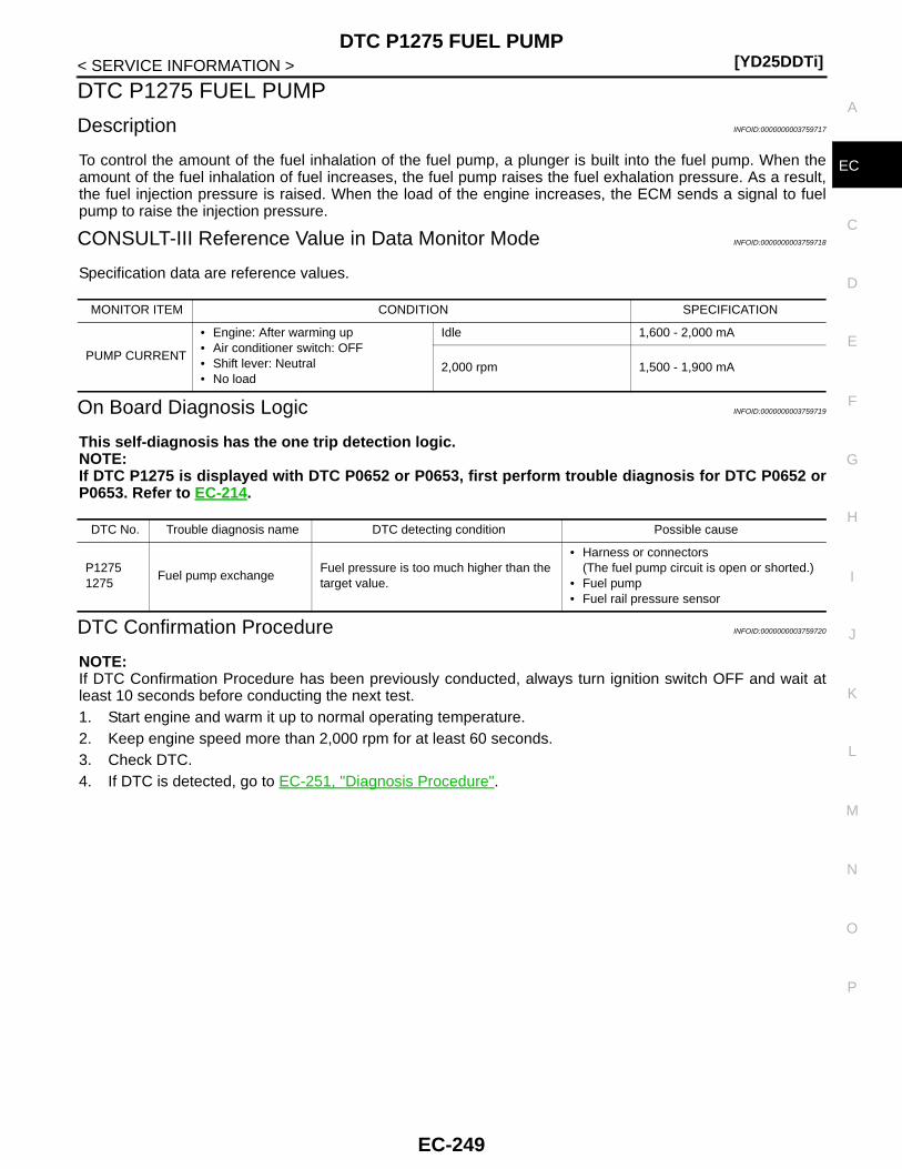
DTC P1275 FUEL PUMP[YD25DDTi]
C
D
E
F
G
H
I
J
K
L
M
A
C
N
P
O
< SERVICE INFORMATION >
E
DTC P1275 FUEL PUMP
Description INFOID:0000000003759717
To control the amount of the fuel inhalation of the fuel pump, a plunger is built into the fuel pump. When theamount of the fuel inhalation of fuel increases, the fuel pump raises the fuel exhalation pressure. As a result,the fuel injection pressure is raised. When the load of the engine increases, the ECM sends a signal to fuelpump to raise the injection pressure.
CONSULT-III Reference Value in Data Monitor Mode INFOID:0000000003759718
Specification data are reference values.
On Board Diagnosis Logic INFOID:0000000003759719
This self-diagnosis has the one trip detection logic.NOTE:If DTC P1275 is displayed with DTC P0652 or P0653, first perform trouble diagnosis for DTC P0652 orP0653. Refer to EC-214.
DTC Confirmation Procedure INFOID:0000000003759720
NOTE:If DTC Confirmation Procedure has been previously conducted, always turn ignition switch OFF and wait atleast 10 seconds before conducting the next test. 1. Start engine and warm it up to normal operating temperature.2. Keep engine speed more than 2,000 rpm for at least 60 seconds.3. Check DTC.4. If DTC is detected, go to EC-251, "Diagnosis Procedure".
MONITOR ITEM CONDITION SPECIFICATION
PUMP CURRENT
• Engine: After warming up• Air conditioner switch: OFF• Shift lever: Neutral• No load
Idle 1,600 - 2,000 mA
2,000 rpm 1,500 - 1,900 mA
DTC No. Trouble diagnosis name DTC detecting condition Possible cause
P12751275
Fuel pump exchangeFuel pressure is too much higher than the target value.
• Harness or connectors(The fuel pump circuit is open or shorted.)
• Fuel pump• Fuel rail pressure sensor
EC-249
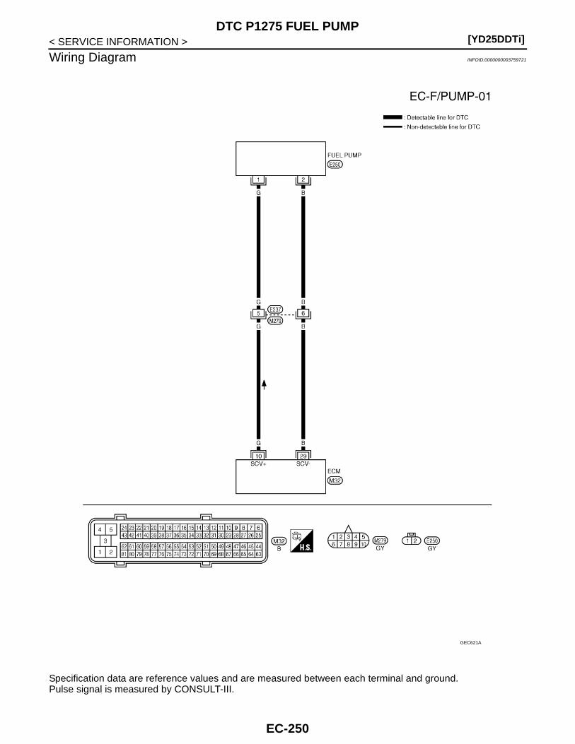
[YD25DDTi]DTC P1275 FUEL PUMP
< SERVICE INFORMATION >
Wiring Diagram INFOID:0000000003759721
Specification data are reference values and are measured between each terminal and ground.Pulse signal is measured by CONSULT-III.
GEC621A
EC-250
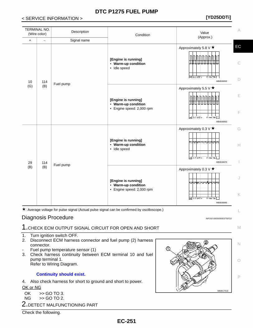
DTC P1275 FUEL PUMP[YD25DDTi]
C
D
E
F
G
H
I
J
K
L
M
A
C
N
P
O
< SERVICE INFORMATION >
E
: Average voltage for pulse signal (Actual pulse signal can be confirmed by oscilloscope.)
Diagnosis Procedure INFOID:0000000003759722
1.CHECK ECM OUTPUT SIGNAL CIRCUIT FOR OPEN AND SHORT
1. Turn ignition switch OFF.2. Disconnect ECM harness connector and fuel pump (2) harness
connector.- Fuel pump temperature sensor (1)3. Check harness continuity between ECM terminal 10 and fuel
pump terminal 1.Refer to Wiring Diagram.
4. Also check harness for short to ground and short to power.OK or NGOK >> GO TO 3.NG >> GO TO 2.
2.DETECT MALFUNCTIONING PART
Check the following.
TERMINAL NO.(Wire color)
DescriptionCondition
Value (Approx.)
+ − Signal name
10(G)
114(B)
Fuel pump
[Engine is running]• Warm-up condition• Idle speed
Approximately 5.8 V
[Engine is running]• Warm-up condition• Engine speed: 2,000 rpm
Approximately 5.5 V
29(B)
114(B)
Fuel pump
[Engine is running]• Warm-up condition• Idle speed
Approximately 0.3 V
[Engine is running]• Warm-up condition• Engine speed: 2,000 rpm
Approximately 0.3 V
MBIB0885E
MBIB0886E
MBIB0887E
MBIB0888E
Continuity should exist.
MBIB1751E
EC-251
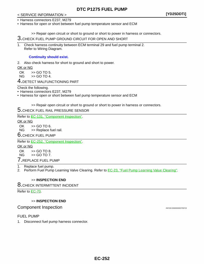
[YD25DDTi]DTC P1275 FUEL PUMP
< SERVICE INFORMATION >• Harness connectors E237, M279• Harness for open or short between fuel pump temperature sensor and ECM
>> Repair open circuit or short to ground or short to power in harness or connectors.
3.CHECK FUEL PUMP GROUND CIRCUIT FOR OPEN AND SHORT
1. Check harness continuity between ECM terminal 29 and fuel pump terminal 2. Refer to Wiring Diagram.
2. Also check harness for short to ground and short to power.OK or NGOK >> GO TO 5.NG >> GO TO 4.
4.DETECT MALFUNCTIONING PART
Check the following.• Harness connectors E237, M279• Harness for open or short between fuel pump temperature sensor and ECM
>> Repair open circuit or short to ground or short to power in harness or connectors.
5.CHECK FUEL RAIL PRESSURE SENSOR
Refer to EC-131, "Component Inspection".OK or NGOK >> GO TO 6.NG >> Replace fuel rail.
6.CHECK FUEL PUMP
Refer to EC-252, "Component Inspection".OK or NGOK >> GO TO 8.NG >> GO TO 7.
7.REPLACE FUEL PUMP
1. Replace fuel pump.2. Perform Fuel Pump Learning Valve Clearing. Refer to EC-23, "Fuel Pump Learning Value Clearing".
>> INSPECTION END
8.CHECK INTERMITTENT INCIDENT
Refer to EC-70.
>> INSPECTION END
Component Inspection INFOID:0000000003759723
FUEL PUMP1. Disconnect fuel pump harness connector.
Continuity should exist.
EC-252
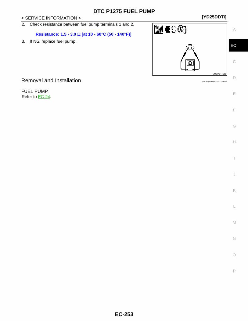
DTC P1275 FUEL PUMP[YD25DDTi]
C
D
E
F
G
H
I
J
K
L
M
A
C
N
P
O
< SERVICE INFORMATION >
E
2. Check resistance between fuel pump terminals 1 and 2.
3. If NG, replace fuel pump.
Removal and Installation INFOID:0000000003759724
FUEL PUMPRefer to EC-24.
Resistance: 1.5 - 3.0 Ω [at 10 - 60°C (50 - 140°F)]
JMBIA1445ZZ
EC-253
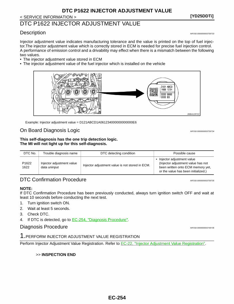
[YD25DDTi]DTC P1622 INJECTOR ADJUSTMENT VALUE
< SERVICE INFORMATION >
DTC P1622 INJECTOR ADJUSTMENT VALUE
Description INFOID:0000000003759733
Injector adjustment value indicates manufacturing tolerance and the value is printed on the top of fuel injec-tor.The injector adjustment value which is correctly stored in ECM is needed for precise fuel injection control.A performance of emission control and a drivability may effect when there is a mismatch between the followingtwo values.• The injector adjustment value stored in ECM• The injector adjustment value of the fuel injector which is installed on the vehicle
On Board Diagnosis Logic INFOID:0000000003759734
This self-diagnosis has the one trip detection logic.The MI will not light up for this self-diagnosis.
DTC Confirmation Procedure INFOID:0000000003759735
NOTE:If DTC Confirmation Procedure has been previously conducted, always turn ignition switch OFF and wait atleast 10 seconds before conducting the next test. 1. Turn ignition switch ON.2. Wait at least 5 seconds.3. Check DTC.4. If DTC is detected, go to EC-254, "Diagnosis Procedure".
Diagnosis Procedure INFOID:0000000003759736
1.PERFORM INJECTOR ADJUSTMENT VALUE REGISTRATION
Perform Injector Adjustment Value Registration. Refer to EC-22, "Injector Adjustment Value Registration".
>> INSPECTION END
Example: Injector adjustment value = D121ABCD1A061234000000000000E6
JMBIA1297ZZ
DTC No. Trouble diagnosis name DTC detecting condition Possible cause
P16221622
Injector adjustment value data uninput
Injector adjustment value is not stored in ECM.
• Injector adjustment value(Injector adjustment value has not been written onto ECM memory yet, or the value has been initialized.)
EC-254

DTC P1623 INJECTOR ADJUSTMENT VALUE[YD25DDTi]
C
D
E
F
G
H
I
J
K
L
M
A
C
N
P
O
< SERVICE INFORMATION >
E
DTC P1623 INJECTOR ADJUSTMENT VALUE
Description INFOID:0000000003759737
Injector adjustment value indicates manufacturing tolerance and the value is printed on the top of fuel injector.The injector adjustment value which is correctly stored in ECM is needed for precise fuel injection control.A performance of emission control and a drivability may effect when there is a mismatch between the followingtwo values.• The injector adjustment value stored in ECM• The injector adjustment value of the fuel injector which is installed on the vehicle
On Board Diagnosis Logic INFOID:0000000003759738
This self-diagnosis has the one trip detection logic.The MI will not light up for this self-diagnosis.
NOTE:This DTC is not detected when injector adjustment value (not correct but existent) is stored in ECM.
DTC Confirmation Procedure INFOID:0000000003759739
NOTE:If DTC Confirmation Procedure has been previously conducted, always turn ignition switch OFF and wait atleast 10 seconds before conducting the next test. 1. Turn ignition switch ON.2. Wait at least 5 seconds.3. Check DTC.4. If DTC is detected, go to EC-255, "Diagnosis Procedure".
Diagnosis Procedure INFOID:0000000003759740
1.CHECK INJECTOR ADJUSTMENT VALUE
1. Turn ignition switch ON.2. Select “ENTER INJCTR CALIB DATA” in “WORK SUPPORT” mode with CONSULT-III.3. Check injector adjustment values displayed on CONSULT-III screen.
Example: Injector adjustment value = D121ABCD1A061234000000000000E6
JMBIA1297ZZ
DTC No. Trouble diagnosis name DTC detecting condition Possible cause
P16231623
Injector adjustment value data error
ECM detects the abnormal value of injector adjustment value.
• CONSULT-III communication status(The status of CONSULT-III communica-tion becomes improper during Injector Adjustment Value Registration.)
• ECM
The value displayed on CONSULT-III screen should be same as injector adjustment value printed on each fuel injector.
EC-255
[YD25DDTi]DTC P1623 INJECTOR ADJUSTMENT VALUE
< SERVICE INFORMATION >OK or NGOK >> GO TO 3.NG >> GO TO 2.
2.PERFORM INJECTOR ADJUSTMENT VALUE REGISTRATION
Perform Injector Adjustment Value Registration. Refer to EC-22, "Injector Adjustment Value Registration". NOTE:When two or more injector adjustment value are improper, it is useful to perform “INJ ADJ VAL CLR” in“WORK SUPPORT” mode with CONSULT-III. And then perform Injector Adjustment Value Registration.
>> GO TO 3.
3.PERFORM DTC CONFIRMATION PROCEDURE
With CONSULT-III1. Select “SELF DIAG RESULTS” mode with CONSULT-III.2. Touch “ERASE”.3. Perform EC-255, "DTC Confirmation Procedure", again.4. Is DTC P1623 displayed again?
With GST1. Select Service $04 with GST.2. Perform EC-255, "DTC Confirmation Procedure", again.3. Is DTC P1623 displayed again?Yes or NoYes >> GO TO 4.No >> INSPECTION END
4.REPLACE ECM
1. Replace ECM.2. Perform initialization of NATS system and registration of all NATS ignition key IDs. Refer to EL-96, "ECM
Re-communicating Function".3. Perform Injector Adjustment Value Registration. Refer to EC-22, "Injector Adjustment Value Registration".4. Perform Fuel Pump Learning Value Clearing. Refer to EC-23, "Fuel Pump Learning Value Clearing".5. Perform EGR Volume Control Valve Closed Position Learning Value Clear. Refer to EC-24, "EGR Volume
Control Valve Closed Position Learning Value Clear".6. Perform EGR Volume Control Valve Closed Position Learning. Refer to EC-24, "EGR Volume Control
Valve Closed Position Learning".
>> INSPECTION END
EC-256
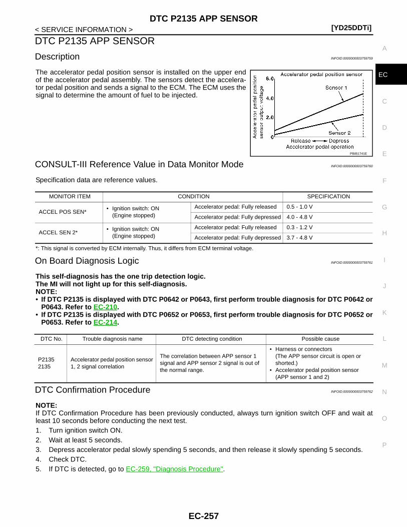
DTC P2135 APP SENSOR[YD25DDTi]
C
D
E
F
G
H
I
J
K
L
M
A
C
N
P
O
< SERVICE INFORMATION >
E
DTC P2135 APP SENSOR
Description INFOID:0000000003759759
The accelerator pedal position sensor is installed on the upper endof the accelerator pedal assembly. The sensors detect the accelera-tor pedal position and sends a signal to the ECM. The ECM uses thesignal to determine the amount of fuel to be injected.
CONSULT-III Reference Value in Data Monitor Mode INFOID:0000000003759760
Specification data are reference values.
*: This signal is converted by ECM internally. Thus, it differs from ECM terminal voltage.
On Board Diagnosis Logic INFOID:0000000003759761
This self-diagnosis has the one trip detection logic.The MI will not light up for this self-diagnosis.NOTE:• If DTC P2135 is displayed with DTC P0642 or P0643, first perform trouble diagnosis for DTC P0642 or
P0643. Refer to EC-210.• If DTC P2135 is displayed with DTC P0652 or P0653, first perform trouble diagnosis for DTC P0652 or
P0653. Refer to EC-214.
DTC Confirmation Procedure INFOID:0000000003759762
NOTE:If DTC Confirmation Procedure has been previously conducted, always turn ignition switch OFF and wait atleast 10 seconds before conducting the next test. 1. Turn ignition switch ON.2. Wait at least 5 seconds.3. Depress accelerator pedal slowly spending 5 seconds, and then release it slowly spending 5 seconds.4. Check DTC.5. If DTC is detected, go to EC-259, "Diagnosis Procedure".
PBIB1741E
MONITOR ITEM CONDITION SPECIFICATION
ACCEL POS SEN*• Ignition switch: ON
(Engine stopped)
Accelerator pedal: Fully released 0.5 - 1.0 V
Accelerator pedal: Fully depressed 4.0 - 4.8 V
ACCEL SEN 2*• Ignition switch: ON
(Engine stopped)
Accelerator pedal: Fully released 0.3 - 1.2 V
Accelerator pedal: Fully depressed 3.7 - 4.8 V
DTC No. Trouble diagnosis name DTC detecting condition Possible cause
P21352135
Accelerator pedal position sensor 1, 2 signal correlation
The correlation between APP sensor 1 signal and APP sensor 2 signal is out of the normal range.
• Harness or connectors(The APP sensor circuit is open or shorted.)
• Accelerator pedal position sensor(APP sensor 1 and 2)
EC-257

[YD25DDTi]DTC P2135 APP SENSOR
< SERVICE INFORMATION >
Wiring Diagram INFOID:0000000003759763
Specification data are reference values and are measured between each terminal and ground.
GEC626A
EC-258
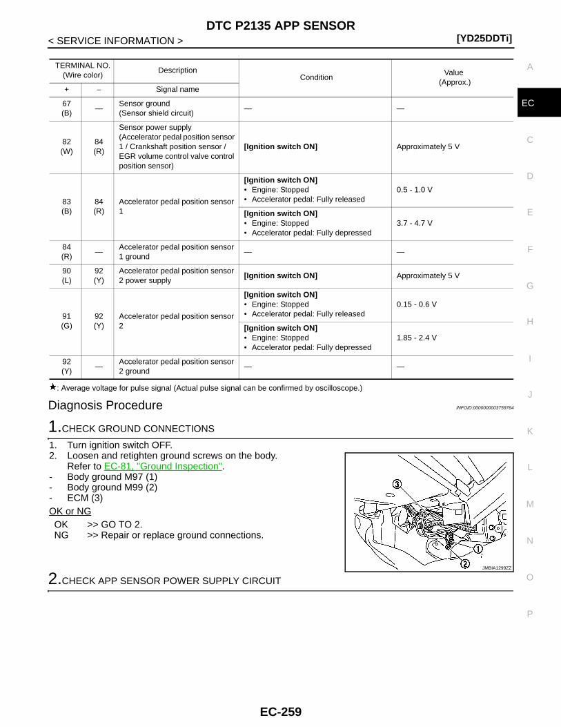
DTC P2135 APP SENSOR[YD25DDTi]
C
D
E
F
G
H
I
J
K
L
M
A
C
N
P
O
< SERVICE INFORMATION >
E
: Average voltage for pulse signal (Actual pulse signal can be confirmed by oscilloscope.)
Diagnosis Procedure INFOID:0000000003759764
1.CHECK GROUND CONNECTIONS
1. Turn ignition switch OFF.2. Loosen and retighten ground screws on the body.
Refer to EC-81, "Ground Inspection".- Body ground M97 (1)- Body ground M99 (2)- ECM (3)OK or NGOK >> GO TO 2.NG >> Repair or replace ground connections.
2.CHECK APP SENSOR POWER SUPPLY CIRCUIT
TERMINAL NO.(Wire color)
DescriptionCondition
Value (Approx.)
+ − Signal name
67(B)
—Sensor ground(Sensor shield circuit)
— —
82(W)
84(R)
Sensor power supply(Accelerator pedal position sensor 1 / Crankshaft position sensor / EGR volume control valve control position sensor)
[Ignition switch ON] Approximately 5 V
83(B)
84(R)
Accelerator pedal position sensor 1
[Ignition switch ON]• Engine: Stopped• Accelerator pedal: Fully released
0.5 - 1.0 V
[Ignition switch ON]• Engine: Stopped• Accelerator pedal: Fully depressed
3.7 - 4.7 V
84(R)
—Accelerator pedal position sensor 1 ground
— —
90(L)
92(Y)
Accelerator pedal position sensor 2 power supply
[Ignition switch ON] Approximately 5 V
91(G)
92(Y)
Accelerator pedal position sensor 2
[Ignition switch ON]• Engine: Stopped• Accelerator pedal: Fully released
0.15 - 0.6 V
[Ignition switch ON]• Engine: Stopped• Accelerator pedal: Fully depressed
1.85 - 2.4 V
92(Y)
—Accelerator pedal position sensor 2 ground
— —
JMBIA1299ZZ
EC-259

[YD25DDTi]DTC P2135 APP SENSOR
< SERVICE INFORMATION >1. Disconnect accelerator pedal position (APP) sensor (1) harness
connector.2. Turn ignition switch ON.
3. Check voltage between APP sensor terminals 4, 6 and groundwith CONSULT-III or tester.
OK or NGOK >> GO TO 3.NG >> Repair open circuit or short to ground or short to power
in harness or connectors.
3.CHECK APP SENSOR GROUND CIRCUIT FOR OPEN AND SHORT
1. Turn ignition switch OFF.2. Disconnect ECM harness connector.3. Check harness continuity between APP sensor terminals 1 and ECM terminal 84, APP sensor terminal 3
and ECM terminal 92.Refer to Wiring Diagram.
4. Also check harness for short to ground and short to power.OK or NGOK >> GO TO 4.NG >> Repair open circuit or short to ground or short to power in harness or connectors.
4.CHECK APP SENSOR INPUT SIGNAL CIRCUIT FOR OPEN AND SHORT
1. Check harness continuity between ECM terminal 83 and APP sensor terminal 5, ECM terminal 91 andAPP sensor terminal 2.Refer to Wiring Diagram.
2. Also check harness for short to ground and short to power.OK or NGOK >> GO TO 5.NG >> Repair open circuit or short to ground or short to power in harness or connectors.
5.CHECK APP SENSOR
Refer to EC-261, "Component Inspection".OK or NGOK >> GO TO 6.NG >> Replace accelerator pedal assembly.
6.CHECK INTERMITTENT INCIDENT
Refer to EC-70.
JMBIA1276ZZ
Voltage: Approximately 5 V
JMBIA1370ZZ
Continuity should exist.
Continuity should exist.
EC-260
DTC P2135 APP SENSOR[YD25DDTi]
C
D
E
F
G
H
I
J
K
L
M
A
C
N
P
O
< SERVICE INFORMATION >
E
>> INSPECTION END
Component Inspection INFOID:0000000003759765
ACCELERATOR PEDAL POSITION SENSOR1. Reconnect all harness connectors disconnected.2. Turn ignition switch ON.3. Check voltage between ECM harness connector terminal as follows.
4. If NG, replace accelerator pedal assembly.
Removal and Installation INFOID:0000000003759766
ACCELERATOR PEDALRefer to “ACCELERATOR CONTROL SYSTEM” in FE section.
ECM
Condition Voltage+ −
Connector Terminal Terminal
M33
83(APP sensor 1 signal)
84(Sensor ground)
Accelerator pedalFully released 0.5 - 1.0 V
Fully depressed 3.7 - 4.7 V
91(APP sensor 2 signal)
92(Sensor ground)
Accelerator pedalFully released 0.15 - 0.6 V
Fully depressed 1.85 - 2.4 V
EC-261
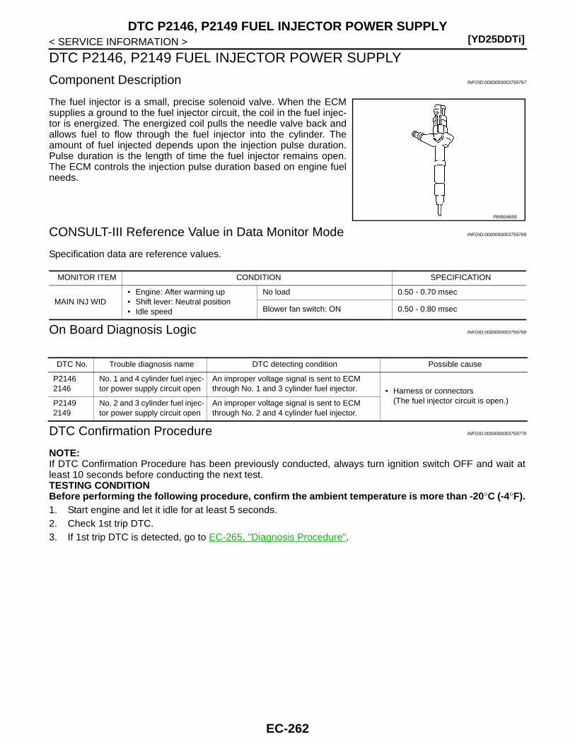
[YD25DDTi]DTC P2146, P2149 FUEL INJECTOR POWER SUPPLY
< SERVICE INFORMATION >
DTC P2146, P2149 FUEL INJECTOR POWER SUPPLY
Component Description INFOID:0000000003759767
The fuel injector is a small, precise solenoid valve. When the ECMsupplies a ground to the fuel injector circuit, the coil in the fuel injec-tor is energized. The energized coil pulls the needle valve back andallows fuel to flow through the fuel injector into the cylinder. Theamount of fuel injected depends upon the injection pulse duration.Pulse duration is the length of time the fuel injector remains open.The ECM controls the injection pulse duration based on engine fuelneeds.
CONSULT-III Reference Value in Data Monitor Mode INFOID:0000000003759768
Specification data are reference values.
On Board Diagnosis Logic INFOID:0000000003759769
DTC Confirmation Procedure INFOID:0000000003759770
NOTE:If DTC Confirmation Procedure has been previously conducted, always turn ignition switch OFF and wait atleast 10 seconds before conducting the next test. TESTING CONDITIONBefore performing the following procedure, confirm the ambient temperature is more than -20°C (-4°F).1. Start engine and let it idle for at least 5 seconds.2. Check 1st trip DTC.3. If 1st trip DTC is detected, go to EC-265, "Diagnosis Procedure".
PBIB0465E
MONITOR ITEM CONDITION SPECIFICATION
MAIN INJ WID• Engine: After warming up• Shift lever: Neutral position• Idle speed
No load 0.50 - 0.70 msec
Blower fan switch: ON 0.50 - 0.80 msec
DTC No. Trouble diagnosis name DTC detecting condition Possible cause
P21462146
No. 1 and 4 cylinder fuel injec-tor power supply circuit open
An improper voltage signal is sent to ECM through No. 1 and 3 cylinder fuel injector. • Harness or connectors
(The fuel injector circuit is open.)P21492149
No. 2 and 3 cylinder fuel injec-tor power supply circuit open
An improper voltage signal is sent to ECM through No. 2 and 4 cylinder fuel injector.
EC-262

DTC P2146, P2149 FUEL INJECTOR POWER SUPPLY[YD25DDTi]
C
D
E
F
G
H
I
J
K
L
M
A
C
N
P
O
< SERVICE INFORMATION >
E
Wiring Diagram INFOID:0000000003759771
Specification data are reference values and are measured between each terminal and ground.Pulse signal is measured by CONSULT-III.
GEC627A
EC-263

[YD25DDTi]DTC P2146, P2149 FUEL INJECTOR POWER SUPPLY
< SERVICE INFORMATION >
: Average voltage for pulse signal (Actual pulse signal can be confirmed by oscilloscope.)
TERMINAL NO.(Wire color)
DescriptionCondition
Value (Approx.)
+ − Signal name
4(L)
114(B)
Fuel injector power supply(For cylinder No. 1 and 3)
[Engine is running]• Warm-up condition• Idle speed
NOTE:The pulse cycle changes depending on rpm at idle
Approximately 7.5 V
5(P)
Fuel injector power supply(For cylinder No. 2 and 4)
[Engine is running]• Warm-up condition• Engine speed: 2,000 rpm
Approximately 8.0 V
21(Y)
114(B)
Fuel injector No. 4[Engine is running]• Warm-up condition• Idle speed
NOTE:The pulse cycle changes depending on rpm at idle
Approximately 7.5 V
22(R)
Fuel injector No. 4
23(W)
Fuel injector No. 2
[Engine is running]• Warm-up condition• Engine speed: 2,000 rpm
Approximately 8.0 V
24(OR)
Fuel injector No. 2
40(G)
114(B)
Fuel injector No. 3[Engine is running]• Warm-up condition• Idle speed
NOTE:The pulse cycle changes depending on rpm at idle
Approximately 7.5 V
41(BR)
Fuel injector No. 3
42(PU)
Fuel injector No. 1
[Engine is running]• Warm-up condition• Engine speed: 2,000 rpm
Approximately 8.0 V
43(SB)
Fuel injector No. 1
MBIB1295E
MBIB1296E
MBIB1297E
MBIB1298E
MBIB1297E
MBIB1298E
EC-264

DTC P2146, P2149 FUEL INJECTOR POWER SUPPLY[YD25DDTi]
C
D
E
F
G
H
I
J
K
L
M
A
C
N
P
O
< SERVICE INFORMATION >
E
Diagnosis Procedure INFOID:0000000003759773
1.CHECK FUEL INJECTOR POWER SUPPLY CIRCUIT FOR OPEN
1. Turn ignition switch OFF.2. Disconnect fuel injector harness connector.3. Disconnect ECM harness connector.4. Check harness continuity between the following terminals corre-
sponding to the malfunctioning cylinder.Refer to Wiring Diagram.
OK or NGOK >> GO TO 2.NG >> Repair open circuit in harness or connectors.
2.CHECK INTERMITTENT INCIDENT
Refer to EC-70.
>> INSPECTION END
TerminalCylinder
ECM Fuel injector
4 1 No.1
5 1 No.2
4 1 No.3
5 1 No.4
Continuity should exist.
JMBIA1282ZZ
EC-265
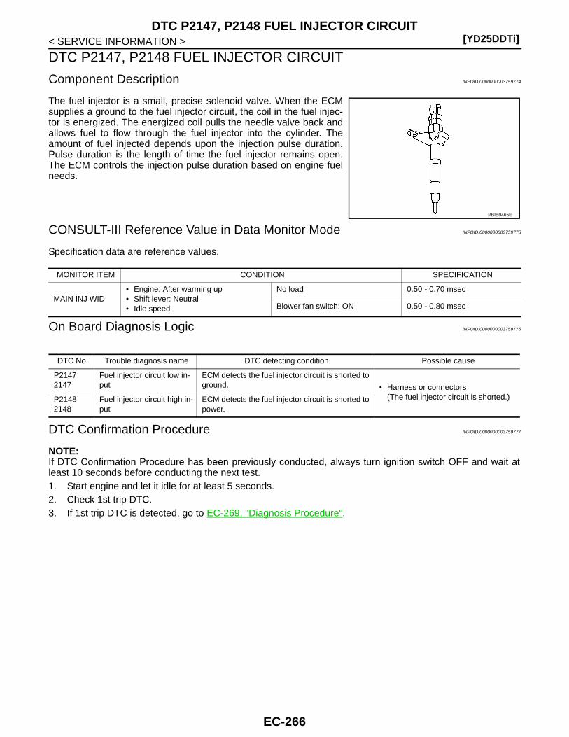
[YD25DDTi]DTC P2147, P2148 FUEL INJECTOR CIRCUIT
< SERVICE INFORMATION >
DTC P2147, P2148 FUEL INJECTOR CIRCUIT
Component Description INFOID:0000000003759774
The fuel injector is a small, precise solenoid valve. When the ECMsupplies a ground to the fuel injector circuit, the coil in the fuel injec-tor is energized. The energized coil pulls the needle valve back andallows fuel to flow through the fuel injector into the cylinder. Theamount of fuel injected depends upon the injection pulse duration.Pulse duration is the length of time the fuel injector remains open.The ECM controls the injection pulse duration based on engine fuelneeds.
CONSULT-III Reference Value in Data Monitor Mode INFOID:0000000003759775
Specification data are reference values.
On Board Diagnosis Logic INFOID:0000000003759776
DTC Confirmation Procedure INFOID:0000000003759777
NOTE:If DTC Confirmation Procedure has been previously conducted, always turn ignition switch OFF and wait atleast 10 seconds before conducting the next test. 1. Start engine and let it idle for at least 5 seconds.2. Check 1st trip DTC.3. If 1st trip DTC is detected, go to EC-269, "Diagnosis Procedure".
PBIB0465E
MONITOR ITEM CONDITION SPECIFICATION
MAIN INJ WID• Engine: After warming up• Shift lever: Neutral• Idle speed
No load 0.50 - 0.70 msec
Blower fan switch: ON 0.50 - 0.80 msec
DTC No. Trouble diagnosis name DTC detecting condition Possible cause
P21472147
Fuel injector circuit low in-put
ECM detects the fuel injector circuit is shorted to ground. • Harness or connectors
(The fuel injector circuit is shorted.)P21482148
Fuel injector circuit high in-put
ECM detects the fuel injector circuit is shorted to power.
EC-266
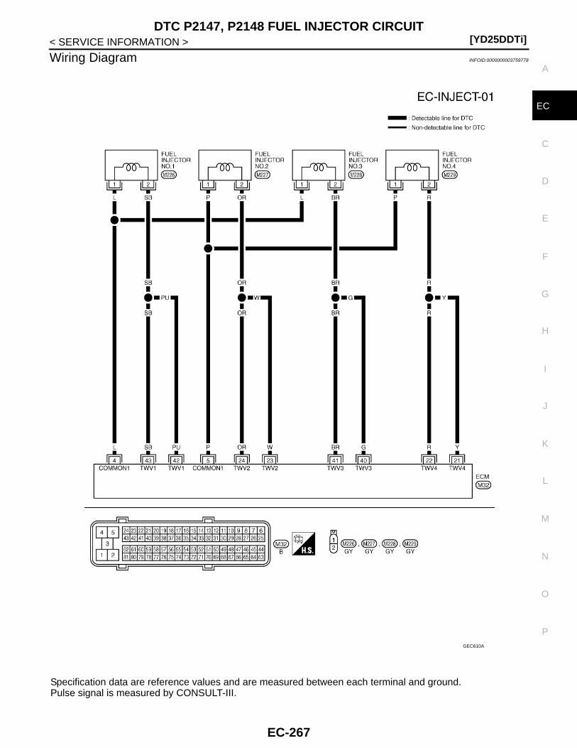
DTC P2147, P2148 FUEL INJECTOR CIRCUIT[YD25DDTi]
C
D
E
F
G
H
I
J
K
L
M
A
C
N
P
O
< SERVICE INFORMATION >
E
Wiring Diagram INFOID:0000000003759778
Specification data are reference values and are measured between each terminal and ground.Pulse signal is measured by CONSULT-III.
GEC610A
EC-267
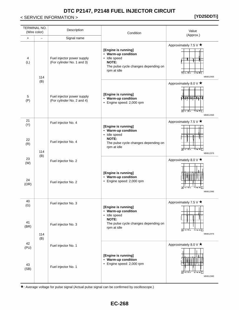
[YD25DDTi]DTC P2147, P2148 FUEL INJECTOR CIRCUIT
< SERVICE INFORMATION >
: Average voltage for pulse signal (Actual pulse signal can be confirmed by oscilloscope.)
TERMINAL NO.(Wire color)
DescriptionCondition
Value (Approx.)
+ − Signal name
4(L)
114(B)
Fuel injector power supply(For cylinder No. 1 and 3)
[Engine is running]• Warm-up condition• Idle speed
NOTE:The pulse cycle changes depending on rpm at idle
Approximately 7.5 V
5(P)
Fuel injector power supply(For cylinder No. 2 and 4)
[Engine is running]• Warm-up condition• Engine speed: 2,000 rpm
Approximately 8.0 V
21(Y)
114(B)
Fuel injector No. 4[Engine is running]• Warm-up condition• Idle speed
NOTE:The pulse cycle changes depending on rpm at idle
Approximately 7.5 V
22(R)
Fuel injector No. 4
23(W)
Fuel injector No. 2
[Engine is running]• Warm-up condition• Engine speed: 2,000 rpm
Approximately 8.0 V
24(OR)
Fuel injector No. 2
40(G)
114(B)
Fuel injector No. 3[Engine is running]• Warm-up condition• Idle speed
NOTE:The pulse cycle changes depending on rpm at idle
Approximately 7.5 V
41(BR)
Fuel injector No. 3
42(PU)
Fuel injector No. 1
[Engine is running]• Warm-up condition• Engine speed: 2,000 rpm
Approximately 8.0 V
43(SB)
Fuel injector No. 1
MBIB1295E
MBIB1296E
MBIB1297E
MBIB1298E
MBIB1297E
MBIB1298E
EC-268

DTC P2147, P2148 FUEL INJECTOR CIRCUIT[YD25DDTi]
C
D
E
F
G
H
I
J
K
L
M
A
C
N
P
O
< SERVICE INFORMATION >
E
Diagnosis Procedure INFOID:0000000003759780
1.CHECK ECM OUTPUT SIGNAL CIRCUIT FOR OPEN OR SHORT
1. Disconnect fuel injector (1) harness connector.
2. Disconnect ECM harness connector. 3. Check harness continuity between the following terminals corre-
sponding to the malfunctioning cylinder.Refer to Wiring Diagram.
4. Also check harness for short to ground and short to power.OK or NGOK >> GO TO 2.NG >> Repair open circuit or short to ground or short to power in harness or connectors.
2.CHECK FUEL INJECTOR
Refer to EC-270, "Removal and Installation".OK or NGOK >> GO TO 4.NG >> GO TO 3.
3.REPLACE FUEL INJECTOR
1. Replace fuel injector of malfunctioning cylinder.2. Perform Injector Adjustment Value Registration. Refer to EC-22, "Injector Adjustment Value Registration".
>> INSPECTION END
4.CHECK INTERMITTENT INCIDENT
Refer to EC-70.
>> INSPECTION END
: Vehicle front
CylinderTerminal
ContinuityFuel injector ECM
No.1
142, 43 Should not exist
4 Should exist
242, 43 Should exist
4 Should not exist
No.2
123, 24 Should not exist
5 Should exist
223, 24 Should exist
5 Should not exist
No.3
140, 41 Should not exist
4 Should exist
240, 41 Should exist
4 Should not exist
No.4
121, 22 Should not exist
5 Should exist
221, 22 Should exist
5 Should not exist
JMBIA1282ZZ
EC-269
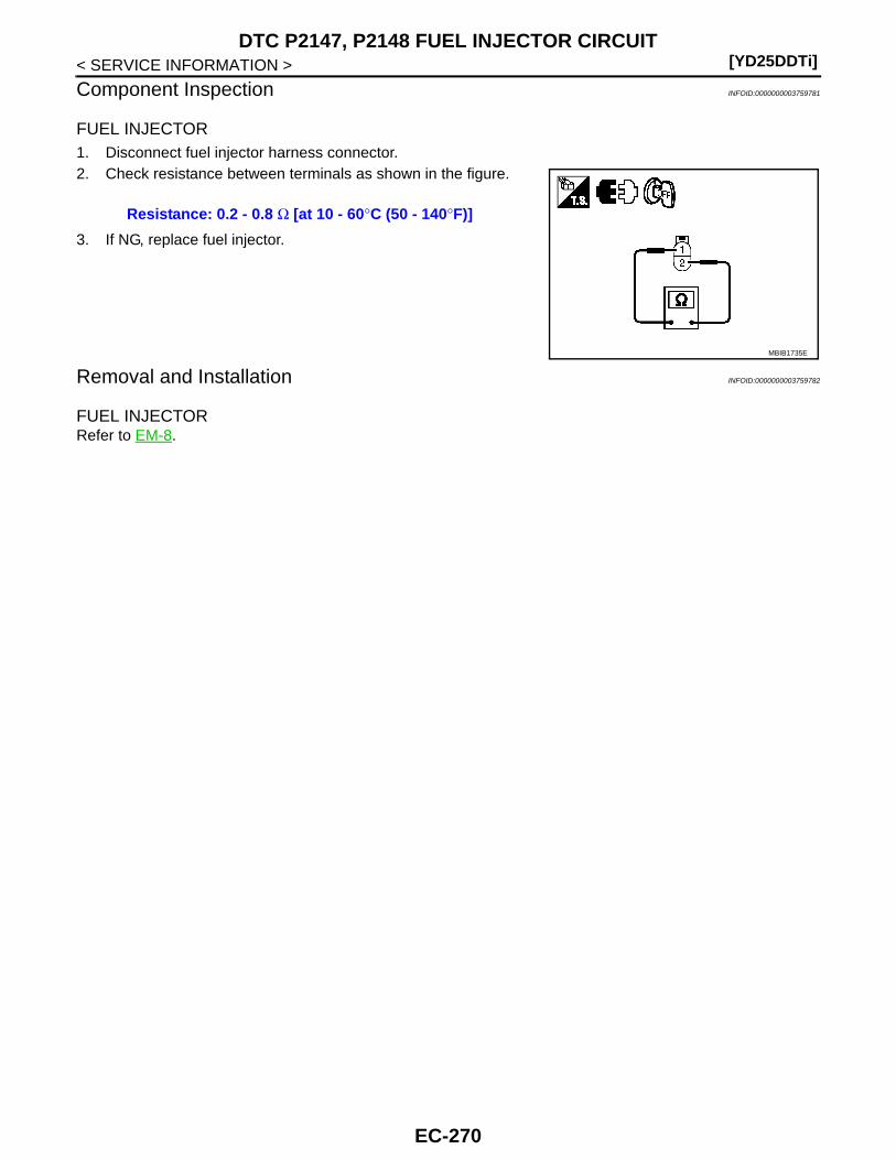
[YD25DDTi]DTC P2147, P2148 FUEL INJECTOR CIRCUIT
< SERVICE INFORMATION >
Component Inspection INFOID:0000000003759781
FUEL INJECTOR1. Disconnect fuel injector harness connector.2. Check resistance between terminals as shown in the figure.
3. If NG, replace fuel injector.
Removal and Installation INFOID:0000000003759782
FUEL INJECTORRefer to EM-8.
Resistance: 0.2 - 0.8 Ω [at 10 - 60°C (50 - 140°F)]
MBIB1735E
EC-270
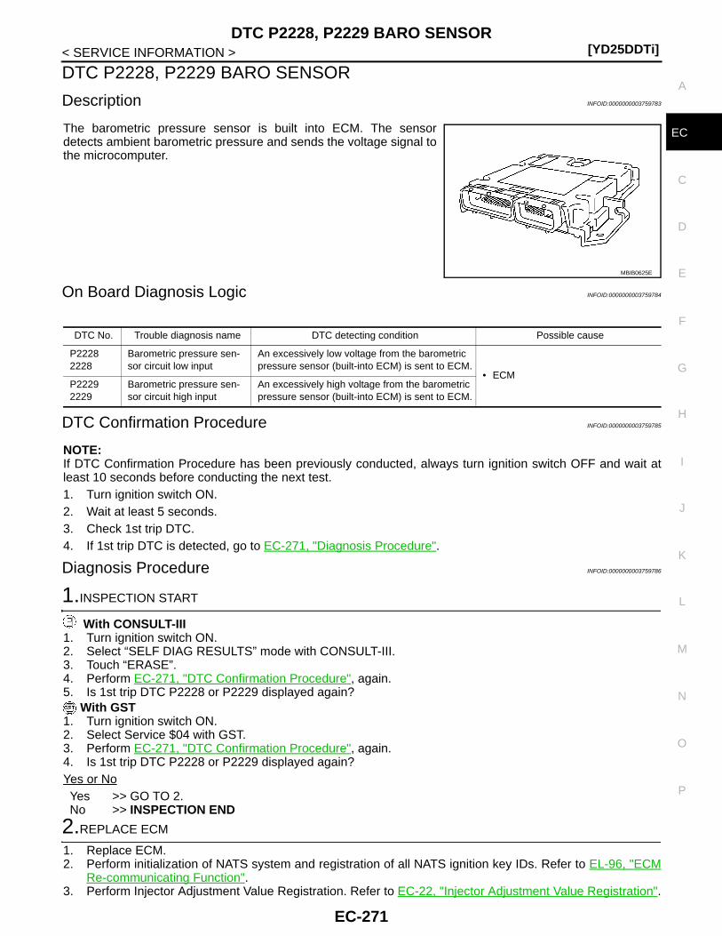
DTC P2228, P2229 BARO SENSOR[YD25DDTi]
C
D
E
F
G
H
I
J
K
L
M
A
C
N
P
O
< SERVICE INFORMATION >
E
DTC P2228, P2229 BARO SENSOR
Description INFOID:0000000003759783
The barometric pressure sensor is built into ECM. The sensordetects ambient barometric pressure and sends the voltage signal tothe microcomputer.
On Board Diagnosis Logic INFOID:0000000003759784
DTC Confirmation Procedure INFOID:0000000003759785
NOTE:If DTC Confirmation Procedure has been previously conducted, always turn ignition switch OFF and wait atleast 10 seconds before conducting the next test. 1. Turn ignition switch ON.2. Wait at least 5 seconds.3. Check 1st trip DTC.4. If 1st trip DTC is detected, go to EC-271, "Diagnosis Procedure".
Diagnosis Procedure INFOID:0000000003759786
1.INSPECTION START
With CONSULT-III1. Turn ignition switch ON.2. Select “SELF DIAG RESULTS” mode with CONSULT-III.3. Touch “ERASE”.4. Perform EC-271, "DTC Confirmation Procedure", again.5. Is 1st trip DTC P2228 or P2229 displayed again?
With GST1. Turn ignition switch ON.2. Select Service $04 with GST.3. Perform EC-271, "DTC Confirmation Procedure", again.4. Is 1st trip DTC P2228 or P2229 displayed again?Yes or NoYes >> GO TO 2.No >> INSPECTION END
2.REPLACE ECM
1. Replace ECM.2. Perform initialization of NATS system and registration of all NATS ignition key IDs. Refer to EL-96, "ECM
Re-communicating Function".3. Perform Injector Adjustment Value Registration. Refer to EC-22, "Injector Adjustment Value Registration".
MBIB0625E
DTC No. Trouble diagnosis name DTC detecting condition Possible cause
P22282228
Barometric pressure sen-sor circuit low input
An excessively low voltage from the barometric pressure sensor (built-into ECM) is sent to ECM.
• ECMP22292229
Barometric pressure sen-sor circuit high input
An excessively high voltage from the barometric pressure sensor (built-into ECM) is sent to ECM.
EC-271

[YD25DDTi]DTC P2228, P2229 BARO SENSOR
< SERVICE INFORMATION >4. Perform Fuel Pump Learning Value Clearing. Refer to EC-23, "Fuel Pump Learning Value Clearing".5. Perform EGR Volume Control Valve Closed Position Learning Value Clear. Refer to EC-24, "EGR Volume
Control Valve Closed Position Learning Value Clear".6. Perform EGR Volume Control Valve Closed Position Learning. Refer to EC-24, "EGR Volume Control
Valve Closed Position Learning".
>> INSPECTION END
EC-272
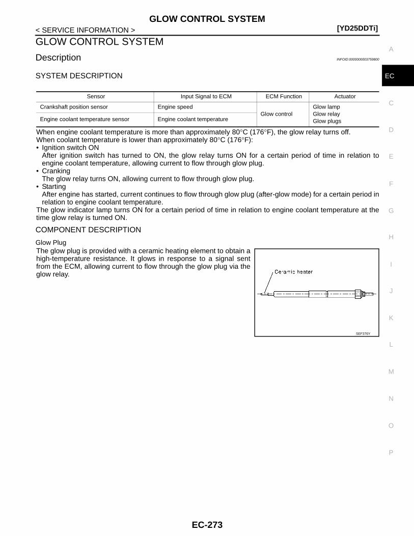
GLOW CONTROL SYSTEM[YD25DDTi]
C
D
E
F
G
H
I
J
K
L
M
A
C
N
P
O
< SERVICE INFORMATION >
E
GLOW CONTROL SYSTEM
Description INFOID:0000000003759800
SYSTEM DESCRIPTION
When engine coolant temperature is more than approximately 80°C (176°F), the glow relay turns off.When coolant temperature is lower than approximately 80°C (176°F):• Ignition switch ON
After ignition switch has turned to ON, the glow relay turns ON for a certain period of time in relation toengine coolant temperature, allowing current to flow through glow plug.
• CrankingThe glow relay turns ON, allowing current to flow through glow plug.
• StartingAfter engine has started, current continues to flow through glow plug (after-glow mode) for a certain period inrelation to engine coolant temperature.
The glow indicator lamp turns ON for a certain period of time in relation to engine coolant temperature at thetime glow relay is turned ON.
COMPONENT DESCRIPTION
Glow PlugThe glow plug is provided with a ceramic heating element to obtain ahigh-temperature resistance. It glows in response to a signal sentfrom the ECM, allowing current to flow through the glow plug via theglow relay.
Sensor Input Signal to ECM ECM Function Actuator
Crankshaft position sensor Engine speedGlow control
Glow lampGlow relayGlow plugsEngine coolant temperature sensor Engine coolant temperature
SEF376Y
EC-273

[YD25DDTi]GLOW CONTROL SYSTEM
< SERVICE INFORMATION >
Wiring Diagram INFOID:0000000003759801
Diagnosis Procedure INFOID:0000000003759802
1.INSPECTION START
Check fuel level, fuel supplying system, starter motor, etc.OK or NG
GEC628A
EC-274
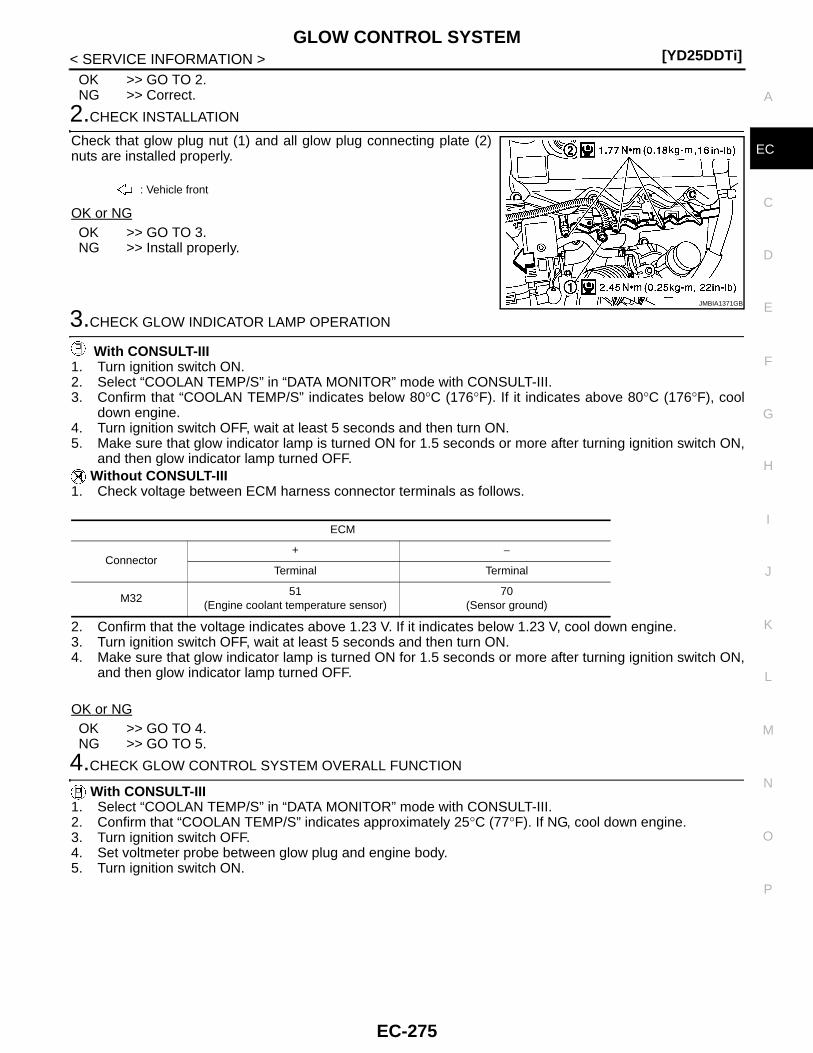
GLOW CONTROL SYSTEM[YD25DDTi]
C
D
E
F
G
H
I
J
K
L
M
A
C
N
P
O
< SERVICE INFORMATION >
E
OK >> GO TO 2.NG >> Correct.
2.CHECK INSTALLATION
Check that glow plug nut (1) and all glow plug connecting plate (2)nuts are installed properly.
OK or NGOK >> GO TO 3.NG >> Install properly.
3.CHECK GLOW INDICATOR LAMP OPERATION
With CONSULT-III1. Turn ignition switch ON.2. Select “COOLAN TEMP/S” in “DATA MONITOR” mode with CONSULT-III.3. Confirm that “COOLAN TEMP/S” indicates below 80°C (176°F). If it indicates above 80°C (176°F), cool
down engine.4. Turn ignition switch OFF, wait at least 5 seconds and then turn ON.5. Make sure that glow indicator lamp is turned ON for 1.5 seconds or more after turning ignition switch ON,
and then glow indicator lamp turned OFF. Without CONSULT-III
1. Check voltage between ECM harness connector terminals as follows.
2. Confirm that the voltage indicates above 1.23 V. If it indicates below 1.23 V, cool down engine.3. Turn ignition switch OFF, wait at least 5 seconds and then turn ON.4. Make sure that glow indicator lamp is turned ON for 1.5 seconds or more after turning ignition switch ON,
and then glow indicator lamp turned OFF.
OK or NGOK >> GO TO 4.NG >> GO TO 5.
4.CHECK GLOW CONTROL SYSTEM OVERALL FUNCTION
With CONSULT-III1. Select “COOLAN TEMP/S” in “DATA MONITOR” mode with CONSULT-III.2. Confirm that “COOLAN TEMP/S” indicates approximately 25°C (77°F). If NG, cool down engine.3. Turn ignition switch OFF.4. Set voltmeter probe between glow plug and engine body.5. Turn ignition switch ON.
: Vehicle front
JMBIA1371GB
ECM
Connector+ −
Terminal Terminal
M3251
(Engine coolant temperature sensor)70
(Sensor ground)
EC-275

[YD25DDTi]GLOW CONTROL SYSTEM
< SERVICE INFORMATION >6. Check the voltage between glow plug and engine body under
the following conditions.
Without CONSULT-III1. Check voltage between ECM harness connector terminals as follows.
2. Confirm that the voltage indicates approximately 3.59 V. If NG, cool down engine.3. Turn ignition switch OFF.4. Set voltmeter probe between glow plug and engine body.5. Turn ignition switch ON.
6. Check the voltage between glow plug and engine body underthe following conditions.
OK or NGOK >> INSPECTION ENDNG >> GO TO 7.
5.CHECK DTC
Check that DTC U1000 is not displayed.Yes or NoYes >> Perform trouble diagnoses for DTC U1000, refer to EC-83.No >> GO TO 6.
6.CHECK COMBINATON METER OPERATION
Does combination meter operate normally?Yes or NoYes >> GO TO 15.No >> Check combination meter circuit. Refer to EL-51.
7.CHECK GLOW RELAY POWER SUPPLY CIRCUIT
1. Turn ignition switch OFF.
: Vehicle front
Conditions Voltage
For 20 seconds after turning ignition switch ON Battery voltage
More than 20 seconds after turning ignition switch ON
Approx. 0 V
JMBIA1372ZZ
ECM
Connector+ −
Terminal Terminal
M3251
(Engine coolant temperature sensor)70
(Sensor ground)
: Vehicle front
Conditions Voltage
For 20 seconds after turning ignition switch ON Battery voltage
More than 20 seconds after turning ignition switch ON
Approx. 0 V
JMBIA1372ZZ
EC-276

GLOW CONTROL SYSTEM[YD25DDTi]
C
D
E
F
G
H
I
J
K
L
M
A
C
N
P
O
< SERVICE INFORMATION >
E
2. Disconnect glow relay (1) harness connector.
3. Check voltage between glow relay terminals 1, 3 and groundwith CONSULT-III or tester.
OK or NGOK >> GO TO 9.NG >> GO TO 8.
8.DETECT MALFUNCTIONING PART
Check the following.• 60 A fusible link (letter b)• Harness for open or short between glow relay and battery
>> Repair harness or connectors.
9.CHECK GLOW RELAY OUTPUT SIGNAL CIRCUIT FOR OPEN AND SHORT
1. Disconnect ECM harness connector.2. Check harness continuity between ECM terminal 37 and glow relay terminal 2.
Refer to Wiring Diagram.
3. Also check harness for short to ground and short to power.OK or NGOK >> GO TO 11.NG >> GO TO 10.
10.DETECT MALFUNCTIONING PART
Check the following.• Harness connectors E101, M5• Harness for open or short between glow relay and ECM
>> Repair open circuit or short to ground or short to power in harness or connectors.
11.CHECK HARNESS CONTINUITY BETWEEN GLOW RELAY AND GLOW PLUG FOR OPEN ANDSHORT
1. Disconnect glow plug harness connector.2. Check harness continuity between glow relay terminal 5 and glow plug harness connector.
Refer to Wiring Diagram.
3. Also check harness for short to ground and short to power.
: Vehicle front
JMBIA1275ZZ
Voltage: Battery voltage
PBIB1413E
Continuity should exist.
Continuity should exist.
EC-277
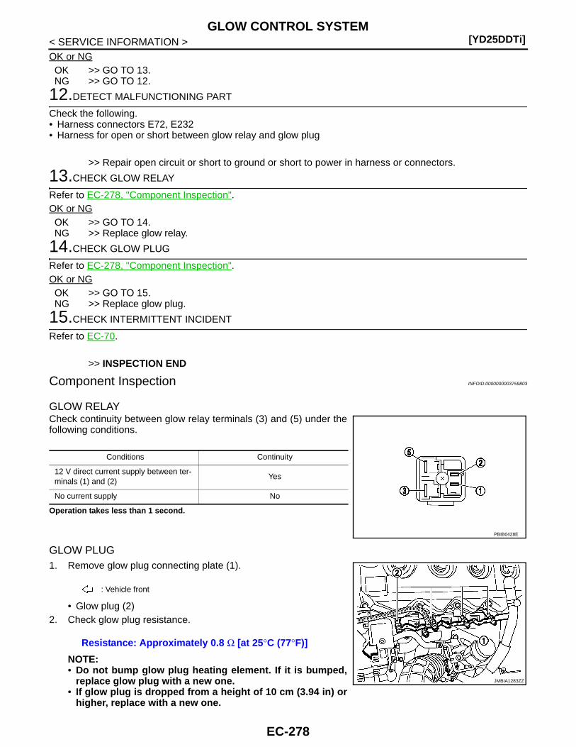
[YD25DDTi]GLOW CONTROL SYSTEM
< SERVICE INFORMATION >OK or NGOK >> GO TO 13.NG >> GO TO 12.
12.DETECT MALFUNCTIONING PART
Check the following.• Harness connectors E72, E232• Harness for open or short between glow relay and glow plug
>> Repair open circuit or short to ground or short to power in harness or connectors.
13.CHECK GLOW RELAY
Refer to EC-278, "Component Inspection".OK or NGOK >> GO TO 14.NG >> Replace glow relay.
14.CHECK GLOW PLUG
Refer to EC-278, "Component Inspection".OK or NGOK >> GO TO 15.NG >> Replace glow plug.
15.CHECK INTERMITTENT INCIDENT
Refer to EC-70.
>> INSPECTION END
Component Inspection INFOID:0000000003759803
GLOW RELAYCheck continuity between glow relay terminals (3) and (5) under thefollowing conditions.
Operation takes less than 1 second.
GLOW PLUG1. Remove glow plug connecting plate (1).
• Glow plug (2)2. Check glow plug resistance.
NOTE:• Do not bump glow plug heating element. If it is bumped,
replace glow plug with a new one.• If glow plug is dropped from a height of 10 cm (3.94 in) or
higher, replace with a new one.
Conditions Continuity
12 V direct current supply between ter-minals (1) and (2)
Yes
No current supply No
PBIB0428E
: Vehicle front
Resistance: Approximately 0.8 Ω [at 25°C (77°F)]
JMBIA1283ZZ
EC-278
GLOW CONTROL SYSTEM[YD25DDTi]
C
D
E
F
G
H
I
J
K
L
M
A
C
N
P
O
< SERVICE INFORMATION >
E
• If glow plug installation hole is contaminated with carbon, remove it with a reamer or suitabletool.
• Hand-tighten glow plug by turning it two or three times, then tighten using a tool to specifiedtorque.
Removal and Installation INFOID:0000000003759804
GLOW PLUGRefer to “CYLINDER HEAD” in EM section.
: 20.1 N-m (2.1 kg-m, 15 ft-lb)
EC-279

[YD25DDTi]HEAT UP SWITCH
< SERVICE INFORMATION >
HEAT UP SWITCH
Description INFOID:0000000003759811
The heat up switch (1) is located on the lower side of the instrumentpanel. This switch is used to speed up the heater's operation whenthe engine is cold. When the ECM received the heat up switch ONsignal, the ECM increases the engine idle speed to 1,400 rpm towarm up engine quickly.This system works when all conditions listed below are met.
CONSULT-III Reference Value in Data Monitor Mode INFOID:0000000003759812
Specification data are reference values.
Heat up switch ON
Shift lever Neutral
Accelerator pedal Fully releasedJMBIA1279ZZ
MONITOR ITEM CONDITION SPECIFICATION
WARM UP SW • Ignition switch: ONHeat up switch: OFF OFF
Heat up switch: ON ON
EC-280
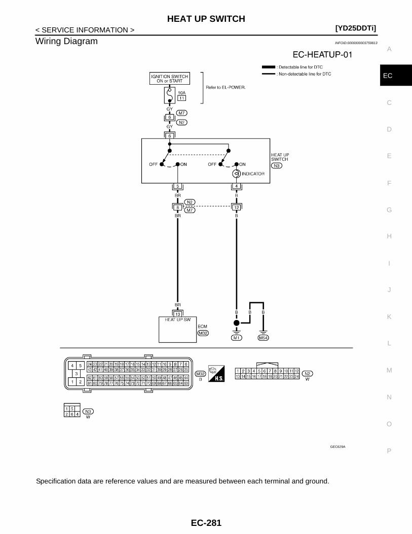
HEAT UP SWITCH[YD25DDTi]
C
D
E
F
G
H
I
J
K
L
M
A
C
N
P
O
< SERVICE INFORMATION >
E
Wiring Diagram INFOID:0000000003759813
Specification data are reference values and are measured between each terminal and ground.
GEC629A
EC-281

[YD25DDTi]HEAT UP SWITCH
< SERVICE INFORMATION >
Diagnosis Procedure INFOID:0000000003759814
1.CHECK OVERALL FUNCTION-I
With CONSULT-III1. Turn ignition switch ON.2. Check “WARM UP SW” in “DATA MONITOR” mode with CONSULT-III under the following conditions.
Without CONSULT-III1. Turn ignition switch ON.2. Check voltage between ECM harness connector terminals as follows.
OK or NGOK >> GO TO 2.NG >> GO TO 3.
2.CHECK OVERALL FUNCTION-II
Check indicator in the heat up switch under the following condition.
OK or NGOK >> INSPECTION ENDNG >> GO TO 7.
3.CHECK HEAT UP SWITCH POWER SUPPLY CIRCUIT
1. Turn heat up switch OFF.2. Turn ignition switch OFF.
TERMINAL NO.(Wire color)
DescriptionCondition
Value (Approx.)
+ − Signal name
13(BR)
114(B)
Heat up switch
[Ignition switch ON]• Heat up switch: OFF
Approximately 0 V
[Ignition switch ON]• Heat up switch: ON
BATTERY VOLTAGE(11 - 14V)
CONDITION WARM UP SW
Heat up switch: OFF OFF
Heat up switch: ON ON
ECM
Condition Voltage+ −
Connector Terminal Connector Terminal
M32 13M32
1
Heat up switch
ON Battery voltage2
3OFF Approx. 0 V
M33 114
CONDITION INDICATION
Heat up switch: OFF OFF
Heat up switch: ON ON
EC-282
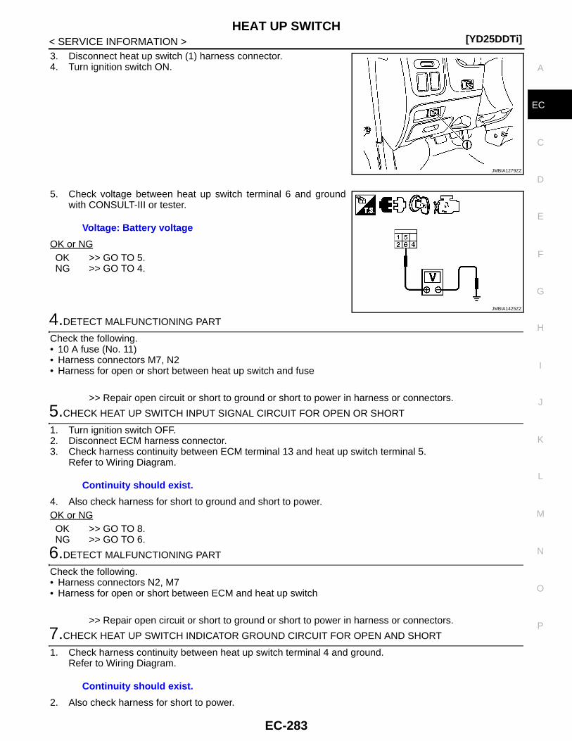
HEAT UP SWITCH[YD25DDTi]
C
D
E
F
G
H
I
J
K
L
M
A
C
N
P
O
< SERVICE INFORMATION >
E
3. Disconnect heat up switch (1) harness connector.4. Turn ignition switch ON.
5. Check voltage between heat up switch terminal 6 and groundwith CONSULT-III or tester.
OK or NGOK >> GO TO 5.NG >> GO TO 4.
4.DETECT MALFUNCTIONING PART
Check the following.• 10 A fuse (No. 11)• Harness connectors M7, N2• Harness for open or short between heat up switch and fuse
>> Repair open circuit or short to ground or short to power in harness or connectors.
5.CHECK HEAT UP SWITCH INPUT SIGNAL CIRCUIT FOR OPEN OR SHORT
1. Turn ignition switch OFF.2. Disconnect ECM harness connector.3. Check harness continuity between ECM terminal 13 and heat up switch terminal 5.
Refer to Wiring Diagram.
4. Also check harness for short to ground and short to power.OK or NGOK >> GO TO 8.NG >> GO TO 6.
6.DETECT MALFUNCTIONING PART
Check the following.• Harness connectors N2, M7• Harness for open or short between ECM and heat up switch
>> Repair open circuit or short to ground or short to power in harness or connectors.
7.CHECK HEAT UP SWITCH INDICATOR GROUND CIRCUIT FOR OPEN AND SHORT
1. Check harness continuity between heat up switch terminal 4 and ground.Refer to Wiring Diagram.
2. Also check harness for short to power.
JMBIA1279ZZ
Voltage: Battery voltage
JMBIA1425ZZ
Continuity should exist.
Continuity should exist.
EC-283

[YD25DDTi]HEAT UP SWITCH
< SERVICE INFORMATION >OK or NGOK >> GO TO 8.NG >> Repair open circuit or short to power in harness or connectors.
8.CHECK HEAT UP SWITCH
Refer to EC-284, "Component Inspection".OK or NGOK >> GO TO 9.NG >> Replace heat up switch.
9.CHECK INTERMITTENT INCIDENT
Refer to EC-70.
>> INSPECTION END
Component Inspection INFOID:0000000003759815
HEAT UP SWITCH1. Turn ignition switch OFF.2. Disconnect heat up switch harness connector.3. Check continuity between heat up switch terminals 5 and 6
under the following conditions.
4. If NG, replace heat up switch.If OK, go to following step.
5. Check continuity between heat up switch terminals 4 and 6under the following conditions.
6. If NG, replace heat up switch.
CONDITION CONTINUITY
Heat up switch: OFF Should not exist
Heat up switch: ON Should exist
JMBIA1426ZZ
CONDITION CONTINUITY
Heat up switch: OFF Should not exist
Heat up switch: ON Should exist
JMBIA1427ZZ
EC-284
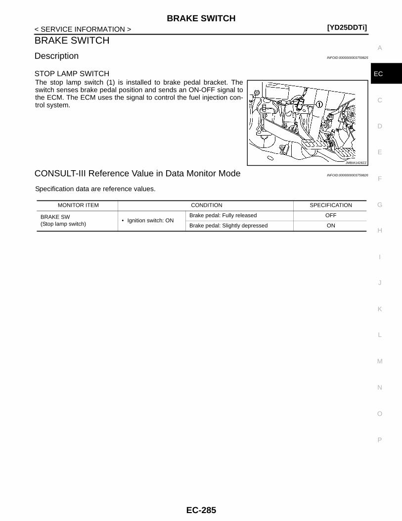
BRAKE SWITCH[YD25DDTi]
C
D
E
F
G
H
I
J
K
L
M
A
C
N
P
O
< SERVICE INFORMATION >
E
BRAKE SWITCH
Description INFOID:0000000003759825
STOP LAMP SWITCHThe stop lamp switch (1) is installed to brake pedal bracket. Theswitch senses brake pedal position and sends an ON-OFF signal tothe ECM. The ECM uses the signal to control the fuel injection con-trol system.
CONSULT-III Reference Value in Data Monitor Mode INFOID:0000000003759826
Specification data are reference values.
JMBIA1428ZZ
MONITOR ITEM CONDITION SPECIFICATION
BRAKE SW(Stop lamp switch)
• Ignition switch: ONBrake pedal: Fully released OFF
Brake pedal: Slightly depressed ON
EC-285
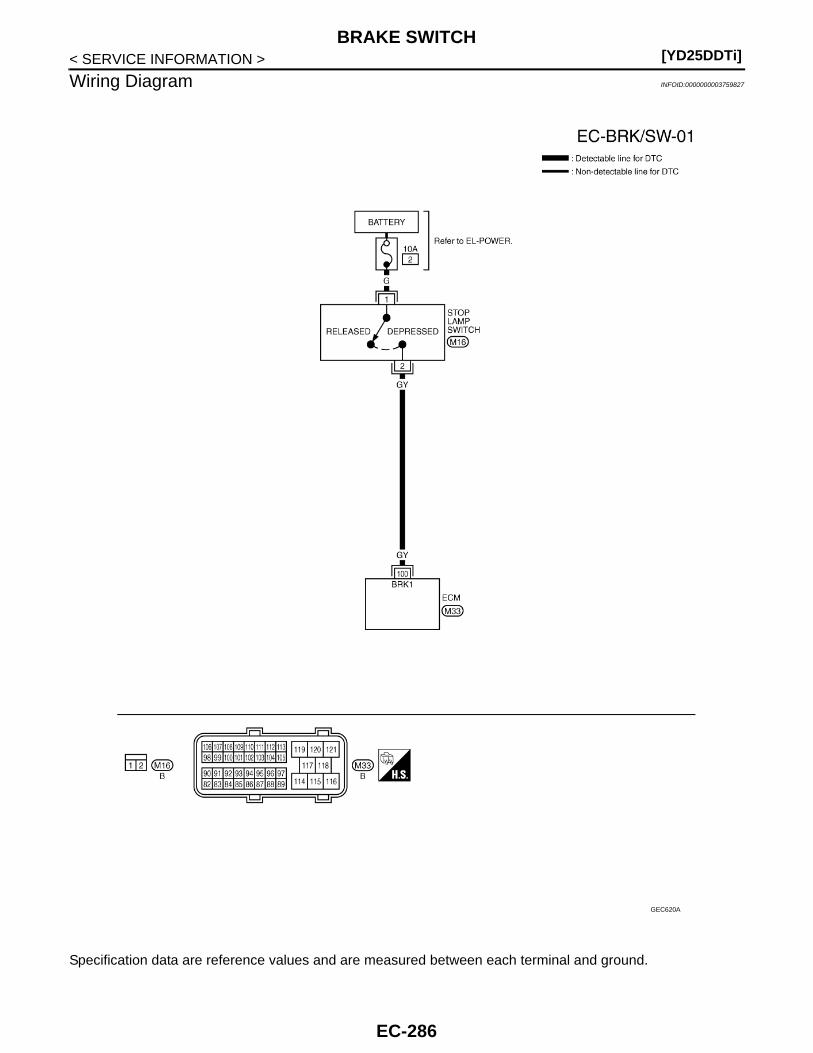
[YD25DDTi]BRAKE SWITCH
< SERVICE INFORMATION >
Wiring Diagram INFOID:0000000003759827
Specification data are reference values and are measured between each terminal and ground.
GEC620A
EC-286
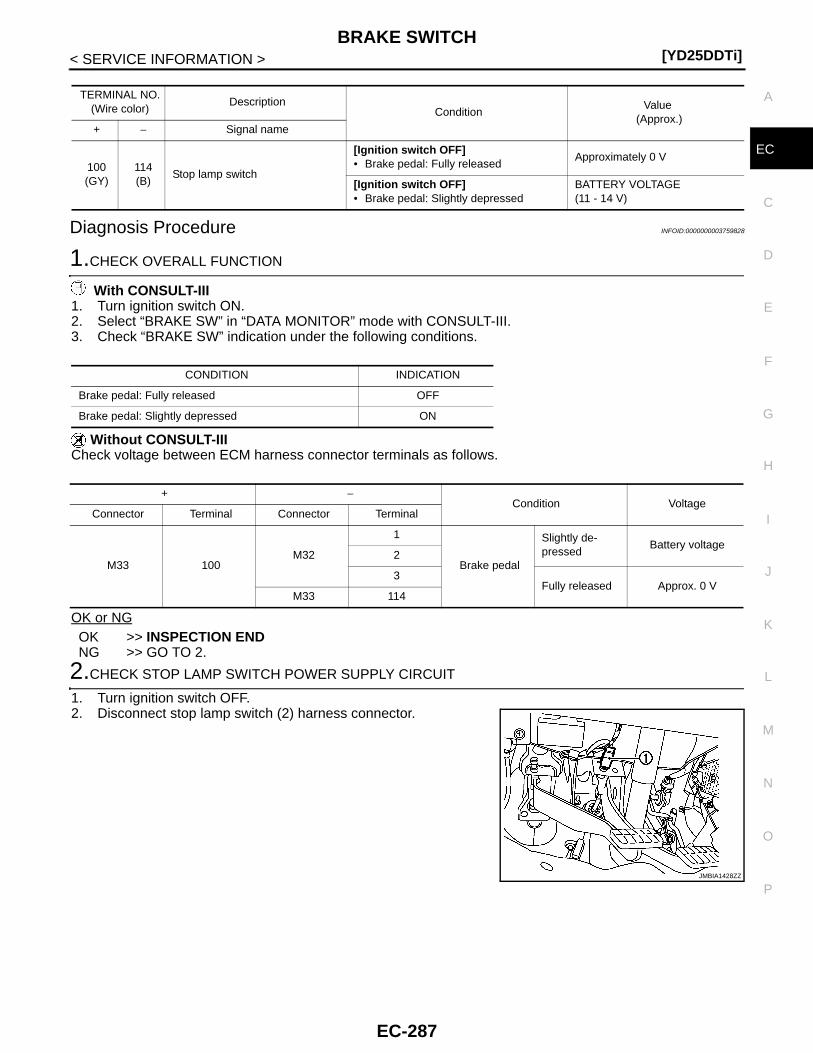
BRAKE SWITCH[YD25DDTi]
C
D
E
F
G
H
I
J
K
L
M
A
C
N
P
O
< SERVICE INFORMATION >
E
Diagnosis Procedure INFOID:0000000003759828
1.CHECK OVERALL FUNCTION
With CONSULT-III1. Turn ignition switch ON.2. Select “BRAKE SW” in “DATA MONITOR” mode with CONSULT-III.3. Check “BRAKE SW” indication under the following conditions.
Without CONSULT-IIICheck voltage between ECM harness connector terminals as follows.
OK or NGOK >> INSPECTION ENDNG >> GO TO 2.
2.CHECK STOP LAMP SWITCH POWER SUPPLY CIRCUIT
1. Turn ignition switch OFF.2. Disconnect stop lamp switch (2) harness connector.
TERMINAL NO.(Wire color)
DescriptionCondition
Value (Approx.)
+ − Signal name
100(GY)
114(B)
Stop lamp switch
[Ignition switch OFF]• Brake pedal: Fully released
Approximately 0 V
[Ignition switch OFF]• Brake pedal: Slightly depressed
BATTERY VOLTAGE(11 - 14 V)
CONDITION INDICATION
Brake pedal: Fully released OFF
Brake pedal: Slightly depressed ON
+ −Condition Voltage
Connector Terminal Connector Terminal
M33 100M32
1
Brake pedal
Slightly de-pressed
Battery voltage2
3Fully released Approx. 0 V
M33 114
JMBIA1428ZZ
EC-287
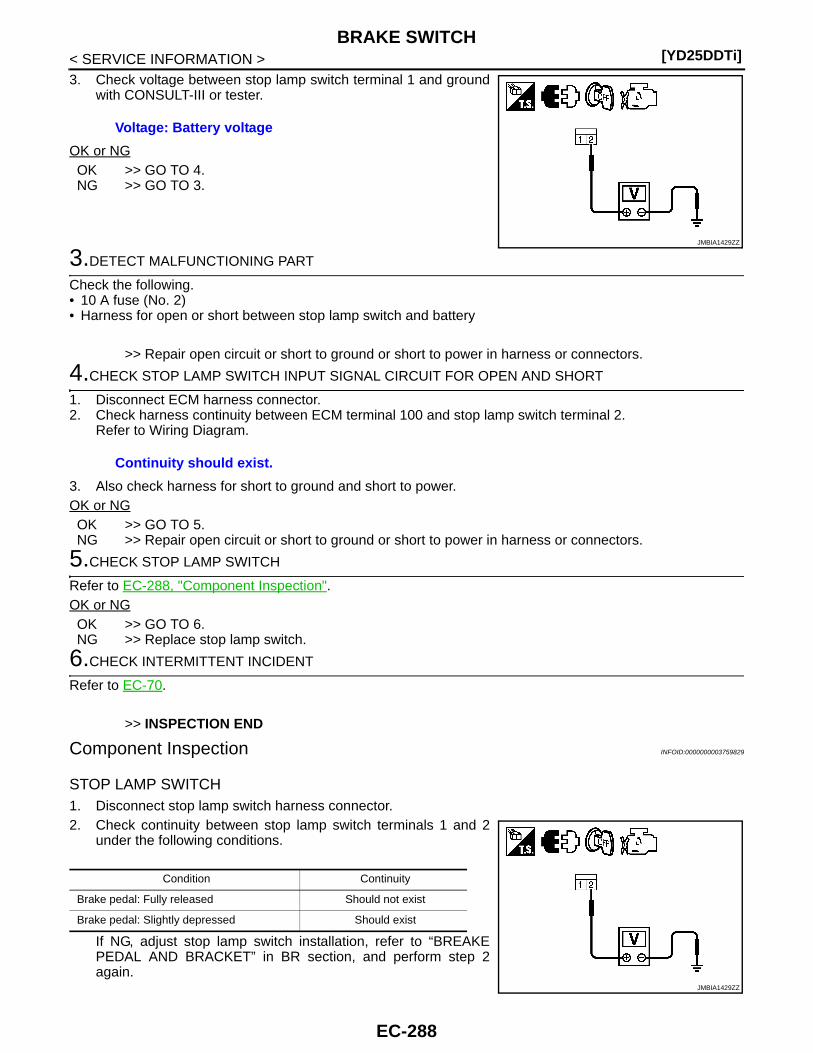
[YD25DDTi]BRAKE SWITCH
< SERVICE INFORMATION >3. Check voltage between stop lamp switch terminal 1 and ground
with CONSULT-III or tester.
OK or NGOK >> GO TO 4.NG >> GO TO 3.
3.DETECT MALFUNCTIONING PART
Check the following.• 10 A fuse (No. 2)• Harness for open or short between stop lamp switch and battery
>> Repair open circuit or short to ground or short to power in harness or connectors.
4.CHECK STOP LAMP SWITCH INPUT SIGNAL CIRCUIT FOR OPEN AND SHORT
1. Disconnect ECM harness connector.2. Check harness continuity between ECM terminal 100 and stop lamp switch terminal 2.
Refer to Wiring Diagram.
3. Also check harness for short to ground and short to power.OK or NGOK >> GO TO 5.NG >> Repair open circuit or short to ground or short to power in harness or connectors.
5.CHECK STOP LAMP SWITCH
Refer to EC-288, "Component Inspection".OK or NGOK >> GO TO 6.NG >> Replace stop lamp switch.
6.CHECK INTERMITTENT INCIDENT
Refer to EC-70.
>> INSPECTION END
Component Inspection INFOID:0000000003759829
STOP LAMP SWITCH1. Disconnect stop lamp switch harness connector.2. Check continuity between stop lamp switch terminals 1 and 2
under the following conditions.
If NG, adjust stop lamp switch installation, refer to “BREAKEPEDAL AND BRACKET” in BR section, and perform step 2again.
Voltage: Battery voltage
JMBIA1429ZZ
Continuity should exist.
Condition Continuity
Brake pedal: Fully released Should not exist
Brake pedal: Slightly depressed Should exist
JMBIA1429ZZ
EC-288

PNP SWITCH[YD25DDTi]
C
D
E
F
G
H
I
J
K
L
M
A
C
N
P
O
< SERVICE INFORMATION >
E
PNP SWITCH
Description INFOID:0000000003759830
When the gear position is in Neutral, park/neutral position is ON. ECM detects the position because the conti-nuity of the line (the “ON” signal) exists.
CONSULT-III Reference Value in Data Monitor Mode INFOID:0000000003759831
Specification data are reference values.
MONITOR ITEM CONDITION SPECIFICATION
P/N POSI SW • Ignition switch: ONShift lever: Neutral position ON
Shift lever: Except above OFF
EC-289
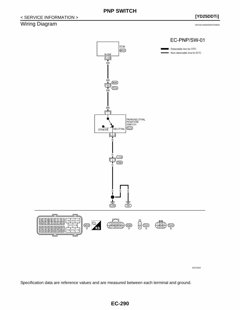
[YD25DDTi]PNP SWITCH
< SERVICE INFORMATION >
Wiring Diagram INFOID:0000000003759832
Specification data are reference values and are measured between each terminal and ground.
GEC630A
EC-290
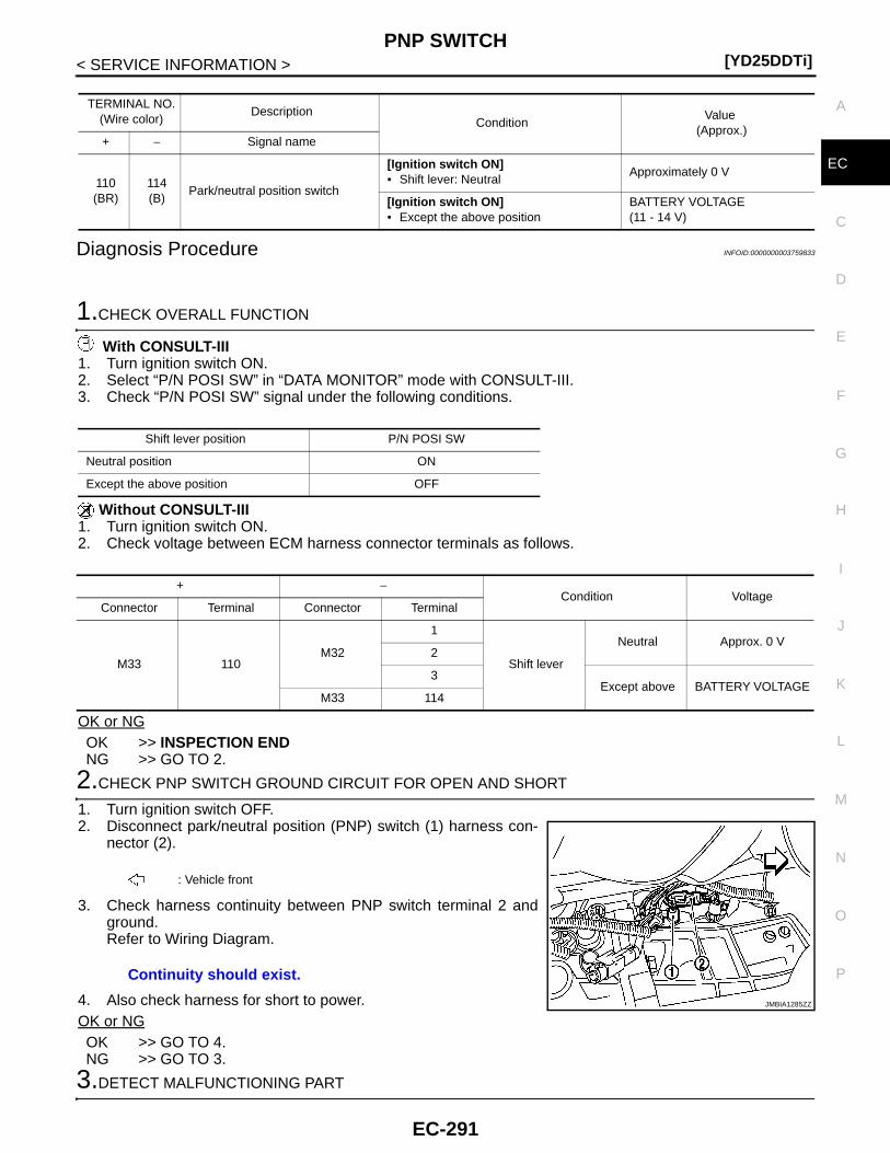
PNP SWITCH[YD25DDTi]
C
D
E
F
G
H
I
J
K
L
M
A
C
N
P
O
< SERVICE INFORMATION >
E
Diagnosis Procedure INFOID:0000000003759833
1.CHECK OVERALL FUNCTION
With CONSULT-III1. Turn ignition switch ON.2. Select “P/N POSI SW” in “DATA MONITOR” mode with CONSULT-III.3. Check “P/N POSI SW” signal under the following conditions.
Without CONSULT-III1. Turn ignition switch ON.2. Check voltage between ECM harness connector terminals as follows.
OK or NGOK >> INSPECTION ENDNG >> GO TO 2.
2.CHECK PNP SWITCH GROUND CIRCUIT FOR OPEN AND SHORT
1. Turn ignition switch OFF.2. Disconnect park/neutral position (PNP) switch (1) harness con-
nector (2).
3. Check harness continuity between PNP switch terminal 2 andground.Refer to Wiring Diagram.
4. Also check harness for short to power.OK or NGOK >> GO TO 4.NG >> GO TO 3.
3.DETECT MALFUNCTIONING PART
TERMINAL NO.(Wire color)
DescriptionCondition
Value (Approx.)
+ − Signal name
110(BR)
114(B)
Park/neutral position switch
[Ignition switch ON]• Shift lever: Neutral
Approximately 0 V
[Ignition switch ON]• Except the above position
BATTERY VOLTAGE(11 - 14 V)
Shift lever position P/N POSI SW
Neutral position ON
Except the above position OFF
+ −Condition Voltage
Connector Terminal Connector Terminal
M33 110M32
1
Shift lever
Neutral Approx. 0 V2
3Except above BATTERY VOLTAGE
M33 114
: Vehicle front
Continuity should exist.
JMBIA1285ZZ
EC-291

[YD25DDTi]PNP SWITCH
< SERVICE INFORMATION >Check the following.• Harness connectors E249, E88• Harness for open or short between PNP switch and ground
>> Repair open circuit or short to ground or short to power in harness or connectors.
4.CHECK PNP SWITCH INPUT SIGNAL CIRCUIT FOR OPEN AND SHORT
1. Disconnect ECM harness connector.2. Check harness continuity between ECM terminal 110 and PNP switch terminal 1.
Refer to Wiring Diagram.
3. Also check harness for short to ground and short to power.OK or NGOK >> GO TO 6.NG >> GO TO 5.
5.DETECT MALFUNCTIONING PART
Check the following.• Harness connectors M285, E254• Harness for open or short between PNP switch and ECM
>> Repair open circuit or short to ground or short to power in harness or connectors.
6.CHECK PARK/NEUTRAL POSITION SWITCH
Refer to “ON-VEHICLE SERVICE” in MT section.OK or NGOK >> GO TO 7.NG >> Replace park/neutral position switch.
7.CHECK INTERMITTENT INCIDENT
Refer to EC-70.
>> INSPECTION END
Continuity should exist.
EC-292
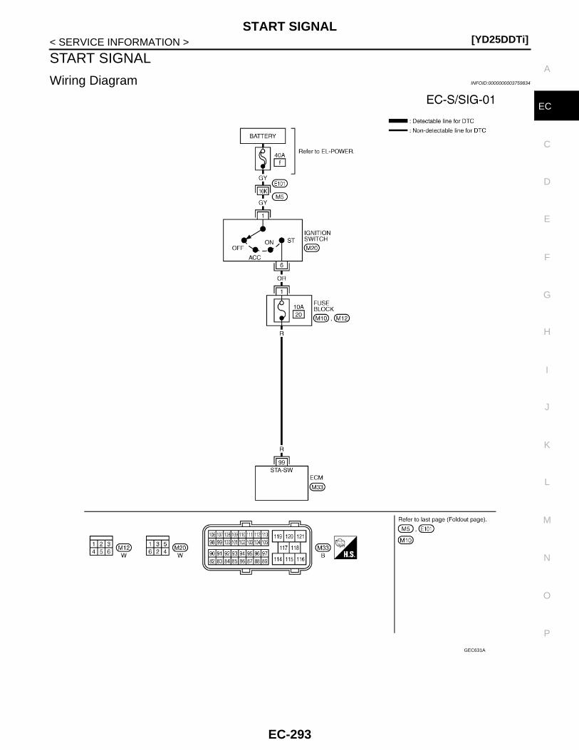
START SIGNAL[YD25DDTi]
C
D
E
F
G
H
I
J
K
L
M
A
C
N
P
O
< SERVICE INFORMATION >
E
START SIGNAL
Wiring Diagram INFOID:0000000003759834
GEC631A
EC-293

[YD25DDTi]START SIGNAL
< SERVICE INFORMATION >
: Average voltage for pulse signal (Actual pulse signal can be confirmed by oscilloscope.)
Diagnosis Procedure INFOID:0000000003759835
1.CHECK START SIGNAL OVERALL FUNCTION
With CONSULT-III1. Turn ignition switch ON.2. Check “START SIGNAL” in “DATA MONITOR” mode with CONSULT-III under the following conditions.
Without CONSULT-IIICheck voltage between ECM harness connector terminals as follows.
OK or NGOK >> INSPECTION ENDNG >> GO TO 2.
2.CHECK START SIGNAL INPUT SIGNAL CIRCUIT
1. Turn ignition switch OFF.2. Disconnect ECM harness connector and ignition switch harness connector.3. Check harness continuity between ECM terminal 99 and ignition switch terminal 6.
Refer to Wiring Diagram.
4. Also check harness for short to ground and short to power.OK or NGOK >> GO TO 4.NG >> GO TO 3.
3.DETECT MALFUNCTIONING PART
Check the following.• 10 A fuse (No. 20)• 40 A fusible link (letter f)• Harness connectors E101, M5• Fuse block (J/B) connectors M12• Ignition switch harness connector M20
TERMINAL NO.(Wire color)
DescriptionCondition
Value (Approx.)
+ − Signal name
99(R)
114(B)
Start signal
[Ignition switch ON] Approximately 0 V
[Ignition switch START]BATTERY VOLTAGE(11 - 14 V)
Condition START SIGNAL
Ignition switch: ON OFF
Ignition switch: START ON
ECM
Condition Voltage+ −
Connector Terminal Connector Terminal
M33 99M32
1
Ignition switch
ON Approx. 0 V2
3START Battery voltage
M33 114
Continuity should exist.
EC-294
START SIGNAL[YD25DDTi]
C
D
E
F
G
H
I
J
K
L
M
A
C
N
P
O
< SERVICE INFORMATION >
E
• Harness for open or short between ECM and fusible link
>> Repair open circuit or short to ground or short to power in harness or connectors.
4.CHECK INTERMITTENT INCIDENT
Refer to EC-70.
>> INSPECTION END
EC-295
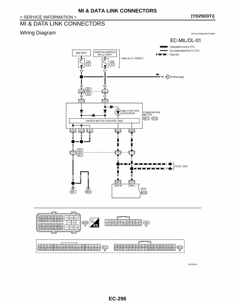
[YD25DDTi]MI & DATA LINK CONNECTORS
< SERVICE INFORMATION >
MI & DATA LINK CONNECTORS
Wiring Diagram INFOID:0000000003759842
GEC632A
EC-296
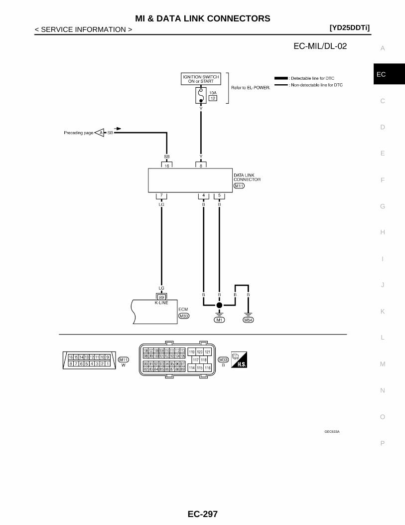
MI & DATA LINK CONNECTORS[YD25DDTi]
C
D
E
F
G
H
I
J
K
L
M
A
C
N
P
O
< SERVICE INFORMATION >
E
GEC633A
EC-297
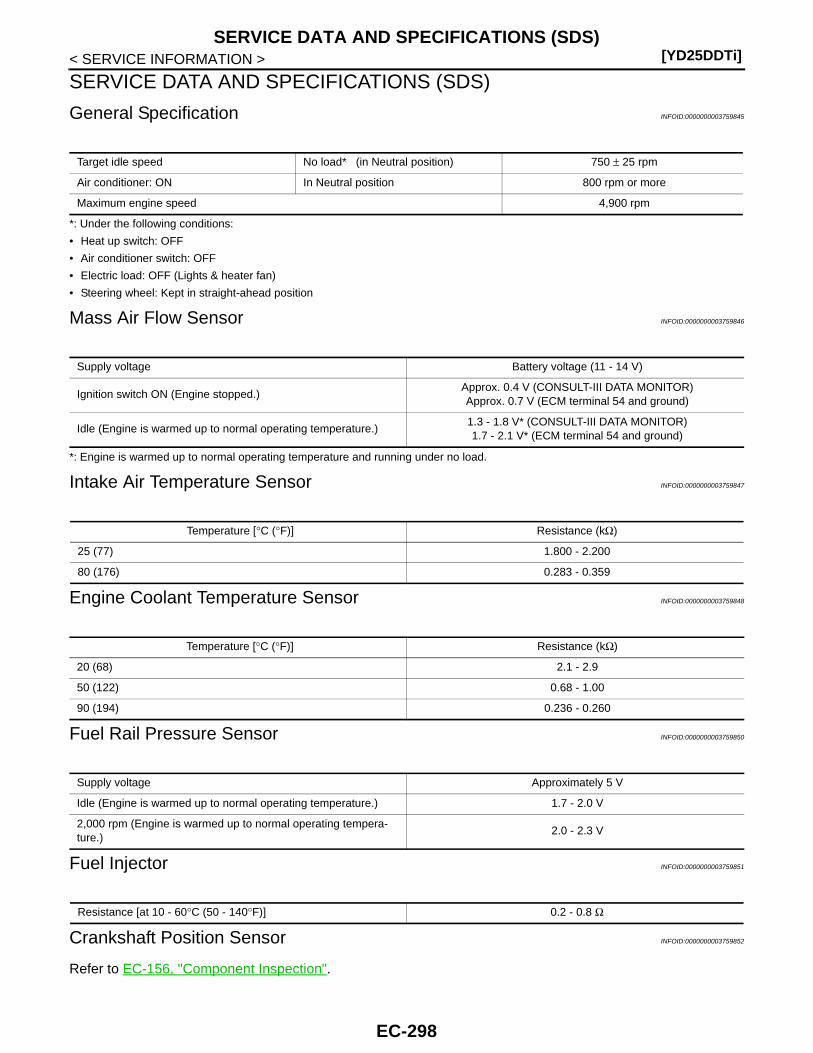
[YD25DDTi]SERVICE DATA AND SPECIFICATIONS (SDS)
< SERVICE INFORMATION >
SERVICE DATA AND SPECIFICATIONS (SDS)
General Specification INFOID:0000000003759845
*: Under the following conditions:
• Heat up switch: OFF
• Air conditioner switch: OFF
• Electric load: OFF (Lights & heater fan)
• Steering wheel: Kept in straight-ahead position
Mass Air Flow Sensor INFOID:0000000003759846
*: Engine is warmed up to normal operating temperature and running under no load.
Intake Air Temperature Sensor INFOID:0000000003759847
Engine Coolant Temperature Sensor INFOID:0000000003759848
Fuel Rail Pressure Sensor INFOID:0000000003759850
Fuel Injector INFOID:0000000003759851
Crankshaft Position Sensor INFOID:0000000003759852
Refer to EC-156, "Component Inspection".
Target idle speed No load* (in Neutral position) 750 ± 25 rpm
Air conditioner: ON In Neutral position 800 rpm or more
Maximum engine speed 4,900 rpm
Supply voltage Battery voltage (11 - 14 V)
Ignition switch ON (Engine stopped.)Approx. 0.4 V (CONSULT-III DATA MONITOR)Approx. 0.7 V (ECM terminal 54 and ground)
Idle (Engine is warmed up to normal operating temperature.)1.3 - 1.8 V* (CONSULT-III DATA MONITOR)1.7 - 2.1 V* (ECM terminal 54 and ground)
Temperature [°C (°F)] Resistance (kΩ)
25 (77) 1.800 - 2.200
80 (176) 0.283 - 0.359
Temperature [°C (°F)] Resistance (kΩ)
20 (68) 2.1 - 2.9
50 (122) 0.68 - 1.00
90 (194) 0.236 - 0.260
Supply voltage Approximately 5 V
Idle (Engine is warmed up to normal operating temperature.) 1.7 - 2.0 V
2,000 rpm (Engine is warmed up to normal operating tempera-ture.)
2.0 - 2.3 V
Resistance [at 10 - 60°C (50 - 140°F)] 0.2 - 0.8 Ω
EC-298
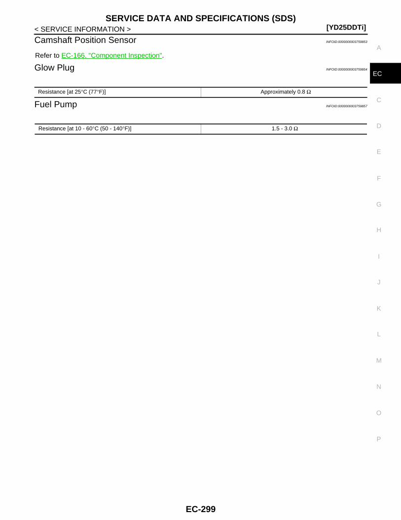
SERVICE DATA AND SPECIFICATIONS (SDS)[YD25DDTi]
C
D
E
F
G
H
I
J
K
L
M
A
C
N
P
O
< SERVICE INFORMATION >
E
Camshaft Position Sensor INFOID:0000000003759853
Refer to EC-166, "Component Inspection".
Glow Plug INFOID:0000000003759854
Fuel Pump INFOID:0000000003759857
Resistance [at 25°C (77°F)] Approximately 0.8 Ω
Resistance [at 10 - 60°C (50 - 140°F)] 1.5 - 3.0 Ω
EC-299


![· Menu_1 Menu_2 Menu_3 Menu_4 Menu_5 Menu_6 Menu_7 Menu_8 Read DTC Clear DTC Data Stream Id Info Action [X] 2.0L L4 LNF Manual Engine Control Module √√√ √ Oil Life Reset](https://img.pdfslide.net/doc/110x75/5e368eaaa1bc8127d02d0693/menu1-menu2-menu3-menu4-menu5-menu6-menu7-menu8-read-dtc-clear-dtc-data.jpg)