Embed Size (px)
Citation preview
International Journal of Scientific & Engineering Research, Volume 9, Issue 10, October-2018
ISSN 2229-5518
IJSER © 2018
http://www.ijser.org
Engine Exhaust System Development & Optimization for FSAE Vehicle
Vasudev Gupta
Abstract - This paper focuses on ways in which the capabilities of an exhaust system are exploited in improving engine performance of an
FSAE vehicle. The exhaust system specifically designed for the engine 2008 Honda CBR 600RR PC40, utilizes literatures on pressure
wave propagation in ducts, reflection and transmission of incident pressure wave due to area discontinuity and impedance mismatch and
driving point impedance of finite ducts, taking into account sensitive parameters such as temperature gradients which influence speed of
propagation of wave and gas momentum variation, in order to determine the optimum dimensions of each exhaust system component,
along with engine noise reduction without generation of back-pressure. Ricardo’s one-dimensional engine simulation software – WAVE has
been used to simulate and understand the sensitivities of various exhaust components on volumetric efficiency, exhaust gas scavenging
efficiency and overall engine performance, to analyze the effect of exhaust gas flow through the combustion chamber and exhaust manifold.
Moreover, meshing three-dimensional CAD parts and importing to WaveBuild workbench has been accomplished by WaveMesher, while
Acoustic Acquisitions in WavePost has been used for engine acoustic simulations. Testing and validation of proposed methodology and
design optimization techniques will be performed.
Index Terms – Acoustic Waves, Exhaust System, FSAE, Motorsports, Optimization, Powertrain Development, Ricardo Wave
—————————— ——————————
1 INTRODUCTION
A s thought by many, the exhaust manifold is not only
utilized in directing exhaust gases post combustion but is
much more potent in influencing the engine performance,
in terms of, volumetric efficiency, exhaust residual,
scavenging efficiency, and thereby augmenting engine
power and torque characteristics. The primary goal of the
exhaust manifold design proposed in this paper is to
create a flatter engine torque curve, without lowering the
peak torque magnitude, throughout the higher rpm,
mainly from 7000-rpm; which has been established to
maintain linear power delivery and predictable
drivability while operating under this range. The
Formula Student (or FS) engineering competitions,
organized by the Formula Student of Automotive
Engineers (or FSAE) is at the acme of engineering
competitions conducted all around the world, and
challenges the students towards innovative thinking,
apart from having profound knowledge, skill and
thinking capability to solve complex engineering
problems. The competition involves both dynamic and
static events, judging the teams and their vehicles for
their knowledge, concept and design understanding,
capabilities of implementing the literature onto their
vehicle, design presentation and to achieve all these
under low expenditures. The dynamic events include
Acceleration, Autocross, Skid pad, Endurance and
Efficiency; The design concept is targeted towards
achieving highest in the Acceleration and Autocross
category. The data acquired from various sensors on
previous vehicles run under these events helped us to
understand the vehicle state and establish the average
engine rpm under which the vehicle operates, which was
above the 7000-rpm region. A flatter torque and linear
power curve has been achieved through careful design
and simulation of the exhaust manifold.
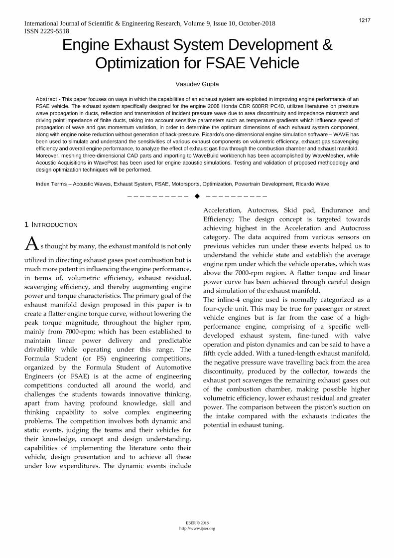
The inline-4 engine used is normally categorized as a
four-cycle unit. This may be true for passenger or street
vehicle engines but is far from the case of a high-
performance engine, comprising of a specific well-
developed exhaust system, fine-tuned with valve
operation and piston dynamics and can be said to have a
fifth cycle added. With a tuned-length exhaust manifold,
the negative pressure wave travelling back from the area
discontinuity, produced by the collector, towards the
exhaust port scavenges the remaining exhaust gases out
of the combustion chamber, making possible higher
volumetric efficiency, lower exhaust residual and greater
power. The comparison between the piston's suction on
the intake compared with the exhausts indicates the
potential in exhaust tuning.
1217
International Journal of Scientific & Engineering Research, Volume 9, Issue 10, October-2018
ISSN 2229-5518
IJSER © 2018
http://www.ijser.org
Not only is scavenging a benefit, the increased port
velocity of incoming air due to suction by piston also
allows for greater volume to be filled into the cylinder,
and when fine-tuned with the intake manifold, the
increased port velocity drives the cylinder filling above
atmospheric pressure just prior to the point of intake
valve closure. Compared with intake, exhaust tuning is
far more potent and can operate over a much wider rpm
band. [1]
To understand the effect of different iterations of the
exhaust system on the engine, along with the extent of
tuning, a theoretical engine model must be made to help
in quick analysis and post processing, which is described
in the next section.
________________
• Vasudev Gupta is currently pursuing bachelor’s degree program in
Automobile Engineering in Manipal Institute of Technology, Manipal, India.
PH-9717210171. E-mail: [email protected]
2 DEVELOPMENT OF A THEORETCAL ENGINE MODEL
ON RICARDO WAVE
The exhaust system, having strong influence on engine
performance, requires prerequisite data and
understanding of the engine, such as firing order,
opening and closing of valves and port geometries, intake
and exhaust cam lobe profile, combustion chamber
geometry; all of which were utilized to create a theoretical
engine model on RICARDO’s one-dimensional engine
simulation software WAVE.
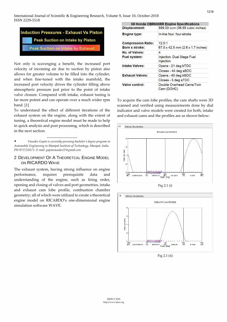
To acquire the cam lobe profiles, the cam shafts were 3D
scanned and verified using measurements done by dial
indicator and valve models were created for both, intake
and exhaust cams and the profiles are as shown below:
Fig 2.1 (i)
Fig 2.1 (ii)
1218
International Journal of Scientific & Engineering Research, Volume 9, Issue 10, October-2018
ISSN 2229-5518
IJSER © 2018
http://www.ijser.org
The Engine General Panel requires the Chen-Flynn
Coefficients for calculation of frictional mean effective
pressure (fmep) of the engine, and the data for Wiebe
Combustion Model to evaluate the combustion
characteristics at a constant rpm, which couldn’t be
determined without experimental testing. These were
initially taken to be default values from WAVE’s tutorial
and were determined at a later stage after creating a
working engine model. The intake and exhaust used were
constructed using ducts and orifices from the RICARDO
library (Fig.2.2).
Fig 2.2
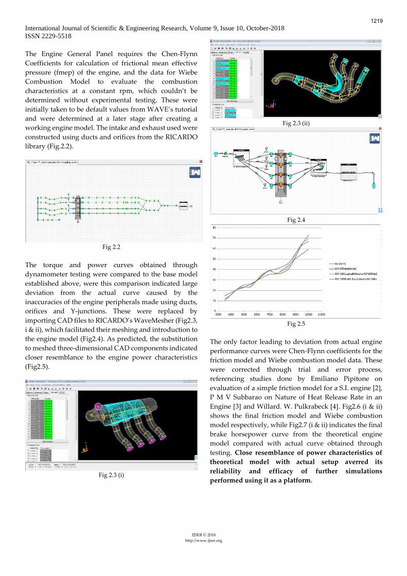
The torque and power curves obtained through
dynamometer testing were compared to the base model
established above, were this comparison indicated large
deviation from the actual curve caused by the
inaccuracies of the engine peripherals made using ducts,
orifices and Y-junctions. These were replaced by
importing CAD files to RICARDO’s WaveMesher (Fig2.3,
i & ii), which facilitated their meshing and introduction to
the engine model (Fig2.4). As predicted, the substitution
to meshed three-dimensional CAD components indicated
closer resemblance to the engine power characteristics
(Fig2.5).
Fig 2.3 (i)
Fig 2.3 (ii)
Fig 2.4
Fig 2.5
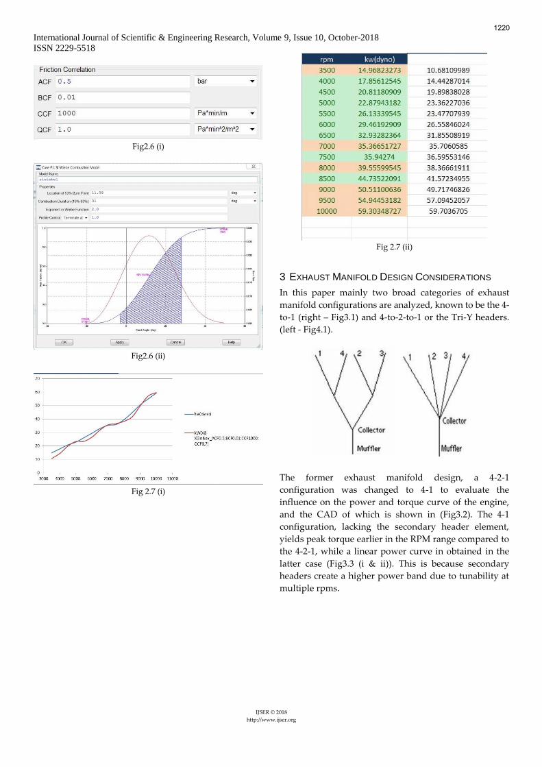
The only factor leading to deviation from actual engine
performance curves were Chen-Flynn coefficients for the
friction model and Wiebe combustion model data. These
were corrected through trial and error process,
referencing studies done by Emiliano Pipitone on
evaluation of a simple friction model for a S.I. engine [2],
P M V Subbarao on Nature of Heat Release Rate in an
Engine [3] and Willard. W. Pulkrabeck [4]. Fig2.6 (i & ii)
shows the final friction model and Wiebe combustion
model respectively, while Fig2.7 (i & ii) indicates the final
brake horsepower curve from the theoretical engine
model compared with actual curve obtained through
testing. Close resemblance of power characteristics of
theoretical model with actual setup averred its
reliability and efficacy of further simulations
performed using it as a platform.
1219
International Journal of Scientific & Engineering Research, Volume 9, Issue 10, October-2018
ISSN 2229-5518
IJSER © 2018
http://www.ijser.org
Fig2.6 (i)
Fig2.6 (ii)
Fig 2.7 (i)
Fig 2.7 (ii)
3 EXHAUST MANIFOLD DESIGN CONSIDERATIONS
In this paper mainly two broad categories of exhaust
manifold configurations are analyzed, known to be the 4-
to-1 (right – Fig3.1) and 4-to-2-to-1 or the Tri-Y headers.
(left - Fig4.1).
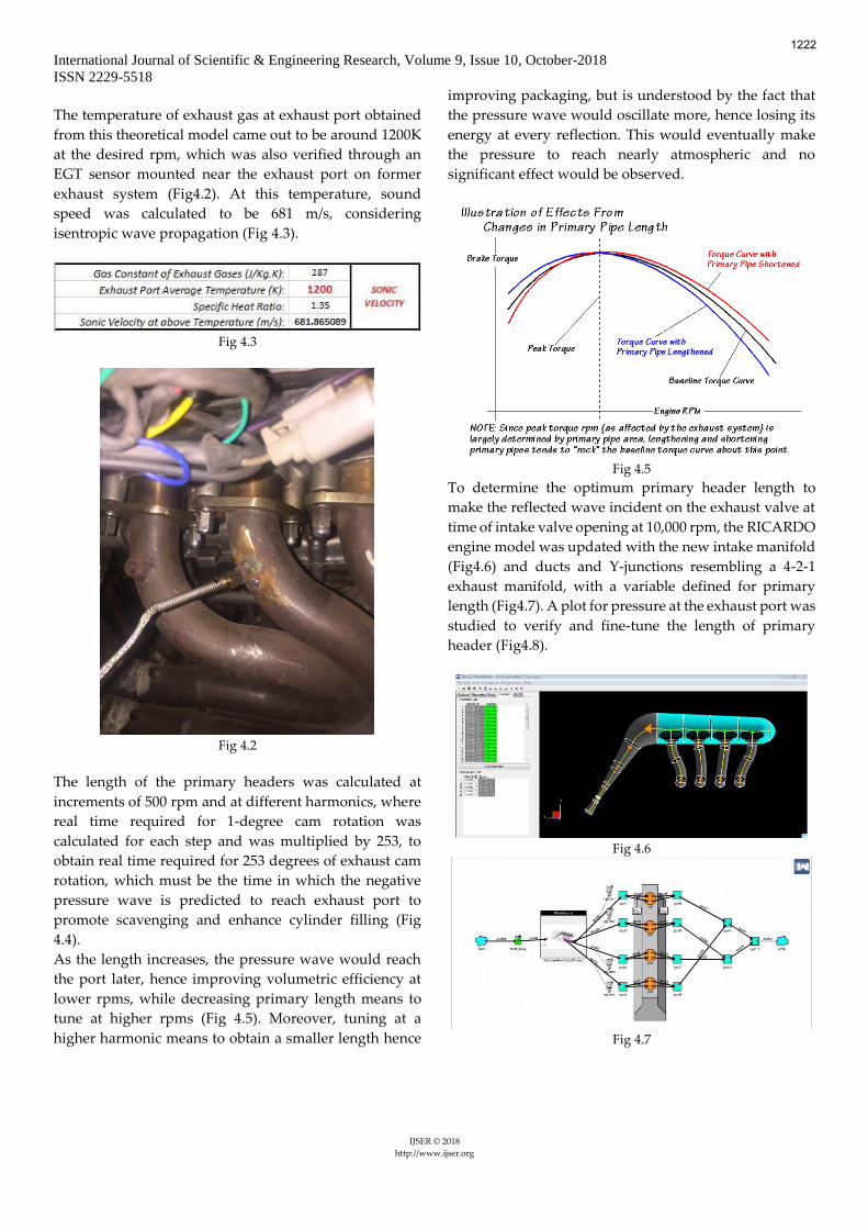
The former exhaust manifold design, a 4-2-1
configuration was changed to 4-1 to evaluate the
influence on the power and torque curve of the engine,
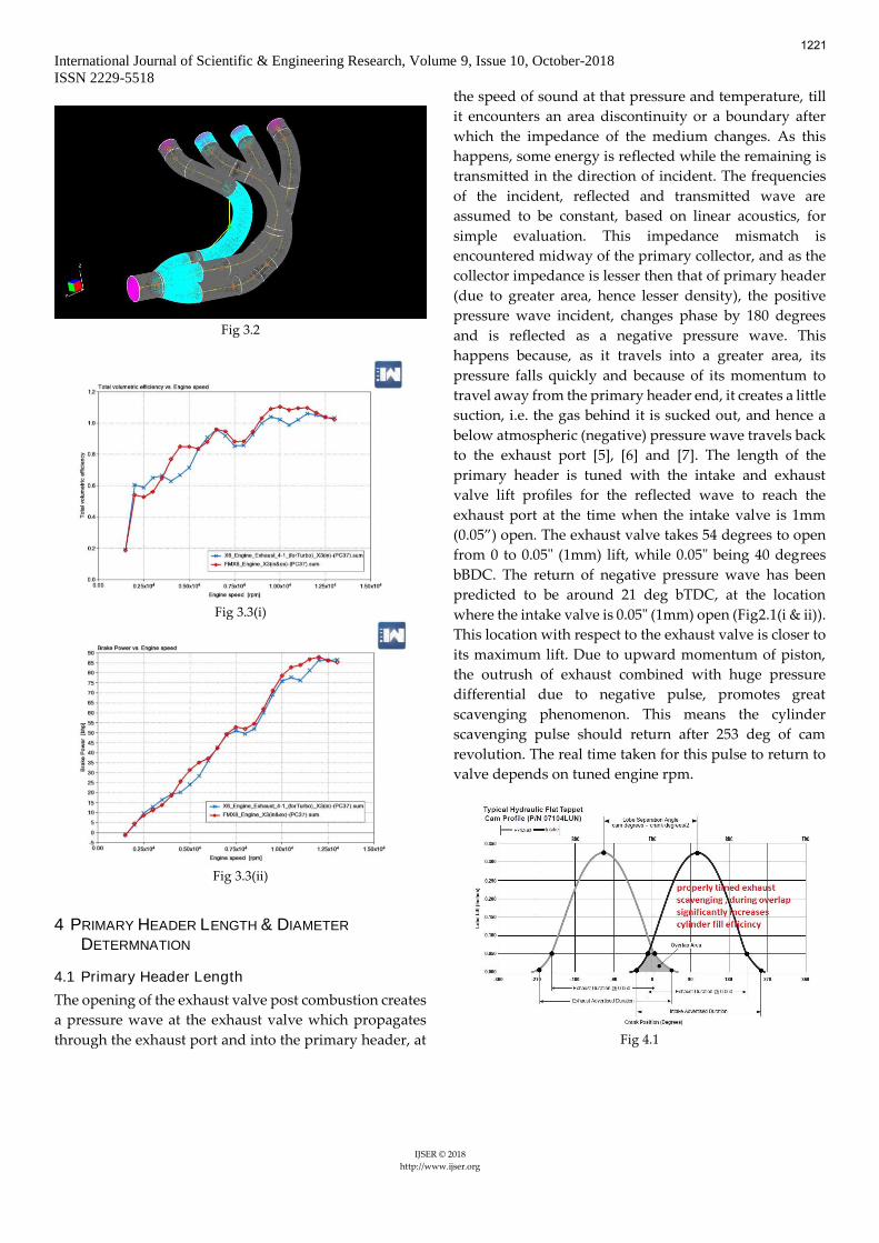
and the CAD of which is shown in (Fig3.2). The 4-1
configuration, lacking the secondary header element,
yields peak torque earlier in the RPM range compared to
the 4-2-1, while a linear power curve in obtained in the
latter case (Fig3.3 (i & ii)). This is because secondary
headers create a higher power band due to tunability at
multiple rpms.
1220
International Journal of Scientific & Engineering Research, Volume 9, Issue 10, October-2018
ISSN 2229-5518
IJSER © 2018
http://www.ijser.org
Fig 3.2
Fig 3.3(i)
Fig 3.3(ii)
4 PRIMARY HEADER LENGTH & DIAMETER
DETERMNATION
4.1 Primary Header Length
The opening of the exhaust valve post combustion creates
a pressure wave at the exhaust valve which propagates
through the exhaust port and into the primary header, at
the speed of sound at that pressure and temperature, till
it encounters an area discontinuity or a boundary after
which the impedance of the medium changes. As this
happens, some energy is reflected while the remaining is
transmitted in the direction of incident. The frequencies
of the incident, reflected and transmitted wave are
assumed to be constant, based on linear acoustics, for
simple evaluation. This impedance mismatch is
encountered midway of the primary collector, and as the
collector impedance is lesser then that of primary header
(due to greater area, hence lesser density), the positive
pressure wave incident, changes phase by 180 degrees
and is reflected as a negative pressure wave. This
happens because, as it travels into a greater area, its
pressure falls quickly and because of its momentum to
travel away from the primary header end, it creates a little
suction, i.e. the gas behind it is sucked out, and hence a
below atmospheric (negative) pressure wave travels back
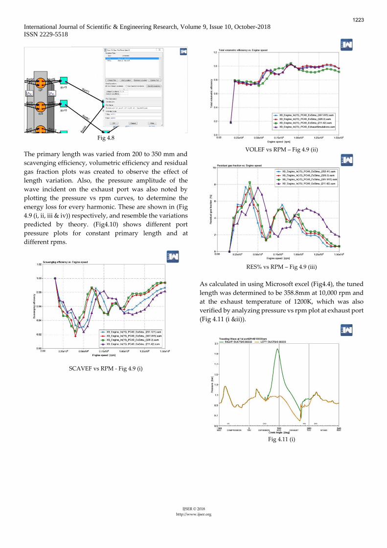
to the exhaust port [5], [6] and [7]. The length of the
primary header is tuned with the intake and exhaust
valve lift profiles for the reflected wave to reach the
exhaust port at the time when the intake valve is 1mm
(0.05”) open. The exhaust valve takes 54 degrees to open
from 0 to 0.05" (1mm) lift, while 0.05" being 40 degrees
bBDC. The return of negative pressure wave has been
predicted to be around 21 deg bTDC, at the location
where the intake valve is 0.05" (1mm) open (Fig2.1(i & ii)).
This location with respect to the exhaust valve is closer to
its maximum lift. Due to upward momentum of piston,
the outrush of exhaust combined with huge pressure
differential due to negative pulse, promotes great
scavenging phenomenon. This means the cylinder
scavenging pulse should return after 253 deg of cam
revolution. The real time taken for this pulse to return to
valve depends on tuned engine rpm.
Fig 4.1
1221
International Journal of Scientific & Engineering Research, Volume 9, Issue 10, October-2018
ISSN 2229-5518
IJSER © 2018
http://www.ijser.org
The temperature of exhaust gas at exhaust port obtained
from this theoretical model came out to be around 1200K
at the desired rpm, which was also verified through an
EGT sensor mounted near the exhaust port on former
exhaust system (Fig4.2). At this temperature, sound
speed was calculated to be 681 m/s, considering
isentropic wave propagation (Fig 4.3).
Fig 4.3
Fig 4.2
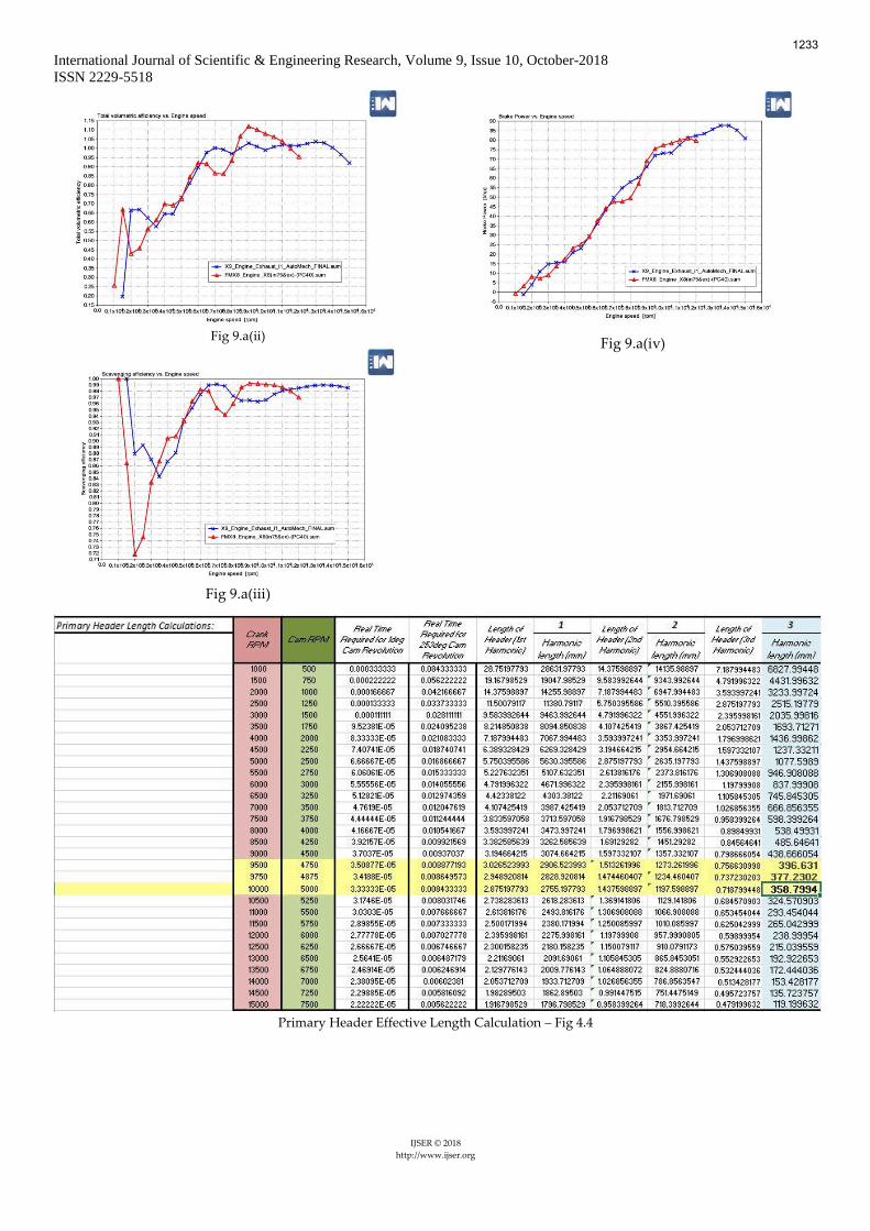
The length of the primary headers was calculated at
increments of 500 rpm and at different harmonics, where
real time required for 1-degree cam rotation was
calculated for each step and was multiplied by 253, to
obtain real time required for 253 degrees of exhaust cam
rotation, which must be the time in which the negative
pressure wave is predicted to reach exhaust port to
promote scavenging and enhance cylinder filling (Fig
4.4).
As the length increases, the pressure wave would reach
the port later, hence improving volumetric efficiency at
lower rpms, while decreasing primary length means to
tune at higher rpms (Fig 4.5). Moreover, tuning at a
higher harmonic means to obtain a smaller length hence
improving packaging, but is understood by the fact that
the pressure wave would oscillate more, hence losing its
energy at every reflection. This would eventually make
the pressure to reach nearly atmospheric and no
significant effect would be observed.
Fig 4.5
To determine the optimum primary header length to
make the reflected wave incident on the exhaust valve at
time of intake valve opening at 10,000 rpm, the RICARDO
engine model was updated with the new intake manifold
(Fig4.6) and ducts and Y-junctions resembling a 4-2-1
exhaust manifold, with a variable defined for primary
length (Fig4.7). A plot for pressure at the exhaust port was
studied to verify and fine-tune the length of primary
header (Fig4.8).
Fig 4.6
Fig 4.7
1222
International Journal of Scientific & Engineering Research, Volume 9, Issue 10, October-2018
ISSN 2229-5518
IJSER © 2018
http://www.ijser.org
Fig 4.8
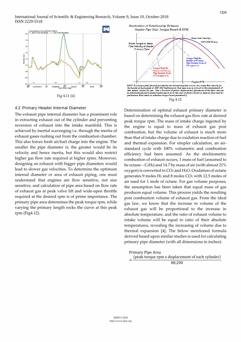
The primary length was varied from 200 to 350 mm and
scavenging efficiency, volumetric efficiency and residual
gas fraction plots was created to observe the effect of
length variation. Also, the pressure amplitude of the
wave incident on the exhaust port was also noted by
plotting the pressure vs rpm curves, to determine the
energy loss for every harmonic. These are shown in (Fig
4.9 (i, ii, iii & iv)) respectively, and resemble the variations
predicted by theory. (Fig4.10) shows different port
pressure plots for constant primary length and at
different rpms.
SCAVEF vs RPM - Fig 4.9 (i)
VOLEF vs RPM – Fig 4.9 (ii)
RES% vs RPM – Fig 4.9 (iii)
As calculated in using Microsoft excel (Fig4.4), the tuned
length was determined to be 358.8mm at 10,000 rpm and
at the exhaust temperature of 1200K, which was also
verified by analyzing pressure vs rpm plot at exhaust port
(Fig 4.11 (i &ii)).
Fig 4.11 (i)
1223
International Journal of Scientific & Engineering Research, Volume 9, Issue 10, October-2018
ISSN 2229-5518
IJSER © 2018
http://www.ijser.org
Fig 4.11 (ii)
4.2 Primary Header Internal Diameter
The exhaust pipe internal diameter has a prominent role
in extracting exhaust out of the cylinder and preventing
reversion of exhaust into the intake manifold. This is
achieved by inertial scavenging i.e. through the inertia of
exhaust gases rushing out from the combustion chamber.
This also forces fresh air/fuel charge into the engine. The
smaller the pipe diameter is, the greater would be its
velocity and hence inertia, but this would also restrict
higher gas flow rate required at higher rpms. Moreover,
designing an exhaust with bigger pipe diameters would
lead to slower gas velocities. To determine the optimum
internal diameter or area of exhaust piping, one must
understand that engines are flow sensitive, not size
sensitive, and calculation of pipe area based on flow rate
of exhaust gas at peak valve lift and wide-open throttle
required at the desired rpm is of prime importance. The
primary pipe area determines the peak torque rpm, while
varying the primary length rocks the curve at this peak
rpm (Fig4.12).
Fig 4.12
Determination of optimal exhaust primary diameter is
based on determining the exhaust gas flow rate at desired
peak torque rpm. The mass of intake charge ingested by
the engine is equal to mass of exhaust gas post
combustion, but the volume of exhaust is much more
than that of intake charge due to oxidation reaction of fuel
and thermal expansion. For simpler calculation, an air-
standard cycle with 100% volumetric and combustion
efficiency had been assumed. As the stochiometric
combustion of exhaust occurs, 1 mass of fuel (assumed to
be octane – C8H8) and 14.7 by mass of air (with almost 21%
oxygen) is converted to CO2 and H2O. Oxidation of octane
generates 9 moles H2 and 8 moles CO2, with 12.5 moles of
air used for 1 mole of octane. For gas volume purposes,
the assumption has been taken that equal mass of gas
produces equal volume. This process yields the resulting
post combustion volume of exhaust gas. From the ideal
gas law, we know that the increase in volume of the
exhaust gas will be proportional to the increase in
absolute temperature, and the ratio of exhaust volume to
intake volume will be equal to ratio of their absolute
temperatures, revealing the increasing of volume due to
thermal expansion [4]. The below mentioned formula
derived based upon similar studies is used for calculating
primary pipe diameter (with all dimensions in inches):
Primary Pipe Area
=(peak torque rpm x displacement of each cylinder)
88,200.
1224
International Journal of Scientific & Engineering Research, Volume 9, Issue 10, October-2018
ISSN 2229-5518
IJSER © 2018
http://www.ijser.org
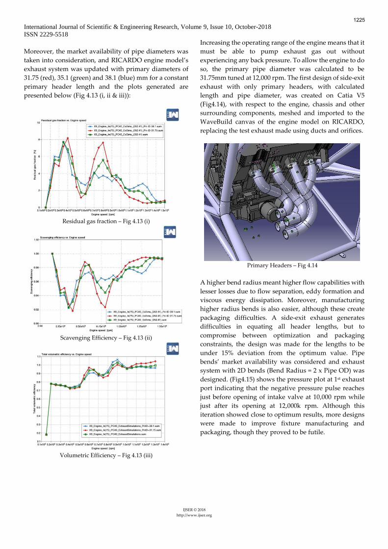
Moreover, the market availability of pipe diameters was
taken into consideration, and RICARDO engine model’s
exhaust system was updated with primary diameters of
31.75 (red), 35.1 (green) and 38.1 (blue) mm for a constant
primary header length and the plots generated are
presented below (Fig 4.13 (i, ii & iii)):
Residual gas fraction – Fig 4.13 (i)
Scavenging Efficiency – Fig 4.13 (ii)
Volumetric Efficiency – Fig 4.13 (iii)
Increasing the operating range of the engine means that it
must be able to pump exhaust gas out without
experiencing any back pressure. To allow the engine to do
so, the primary pipe diameter was calculated to be
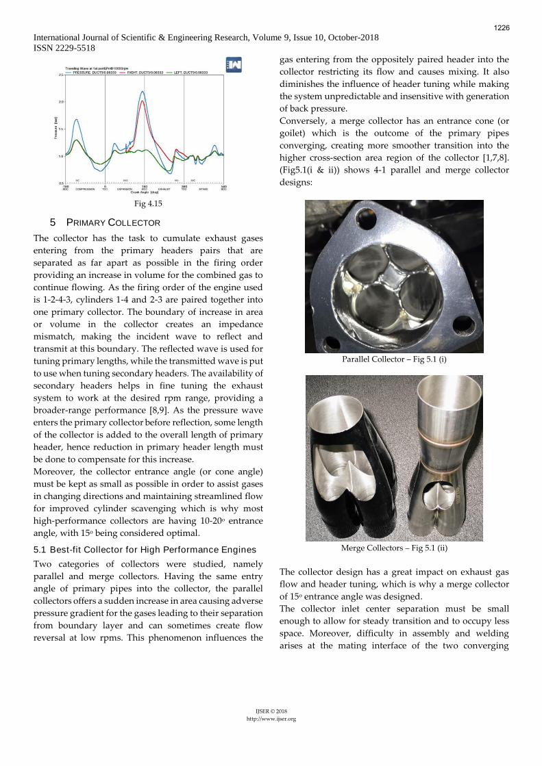
31.75mm tuned at 12,000 rpm. The first design of side-exit
exhaust with only primary headers, with calculated
length and pipe diameter, was created on Catia V5
(Fig4.14), with respect to the engine, chassis and other
surrounding components, meshed and imported to the
WaveBuild canvas of the engine model on RICARDO,
replacing the test exhaust made using ducts and orifices.
Primary Headers – Fig 4.14
A higher bend radius meant higher flow capabilities with
lesser losses due to flow separation, eddy formation and
viscous energy dissipation. Moreover, manufacturing
higher radius bends is also easier, although these create
packaging difficulties. A side-exit exhaust generates
difficulties in equating all header lengths, but to
compromise between optimization and packaging
constraints, the design was made for the lengths to be
under 15% deviation from the optimum value. Pipe
bends’ market availability was considered and exhaust
system with 2D bends (Bend Radius = 2 x Pipe OD) was
designed. (Fig4.15) shows the pressure plot at 1st exhaust
port indicating that the negative pressure pulse reaches
just before opening of intake valve at 10,000 rpm while
just after its opening at 12,000k rpm. Although this
iteration showed close to optimum results, more designs
were made to improve fixture manufacturing and
packaging, though they proved to be futile.
1225
International Journal of Scientific & Engineering Research, Volume 9, Issue 10, October-2018
ISSN 2229-5518
IJSER © 2018
http://www.ijser.org
Fig 4.15
5 PRIMARY COLLECTOR
The collector has the task to cumulate exhaust gases
entering from the primary headers pairs that are
separated as far apart as possible in the firing order
providing an increase in volume for the combined gas to
continue flowing. As the firing order of the engine used
is 1-2-4-3, cylinders 1-4 and 2-3 are paired together into
one primary collector. The boundary of increase in area
or volume in the collector creates an impedance
mismatch, making the incident wave to reflect and
transmit at this boundary. The reflected wave is used for
tuning primary lengths, while the transmitted wave is put
to use when tuning secondary headers. The availability of
secondary headers helps in fine tuning the exhaust
system to work at the desired rpm range, providing a
broader-range performance [8,9]. As the pressure wave
enters the primary collector before reflection, some length
of the collector is added to the overall length of primary
header, hence reduction in primary header length must
be done to compensate for this increase.
Moreover, the collector entrance angle (or cone angle)
must be kept as small as possible in order to assist gases
in changing directions and maintaining streamlined flow
for improved cylinder scavenging which is why most
high-performance collectors are having 10-20o entrance
angle, with 15o being considered optimal.
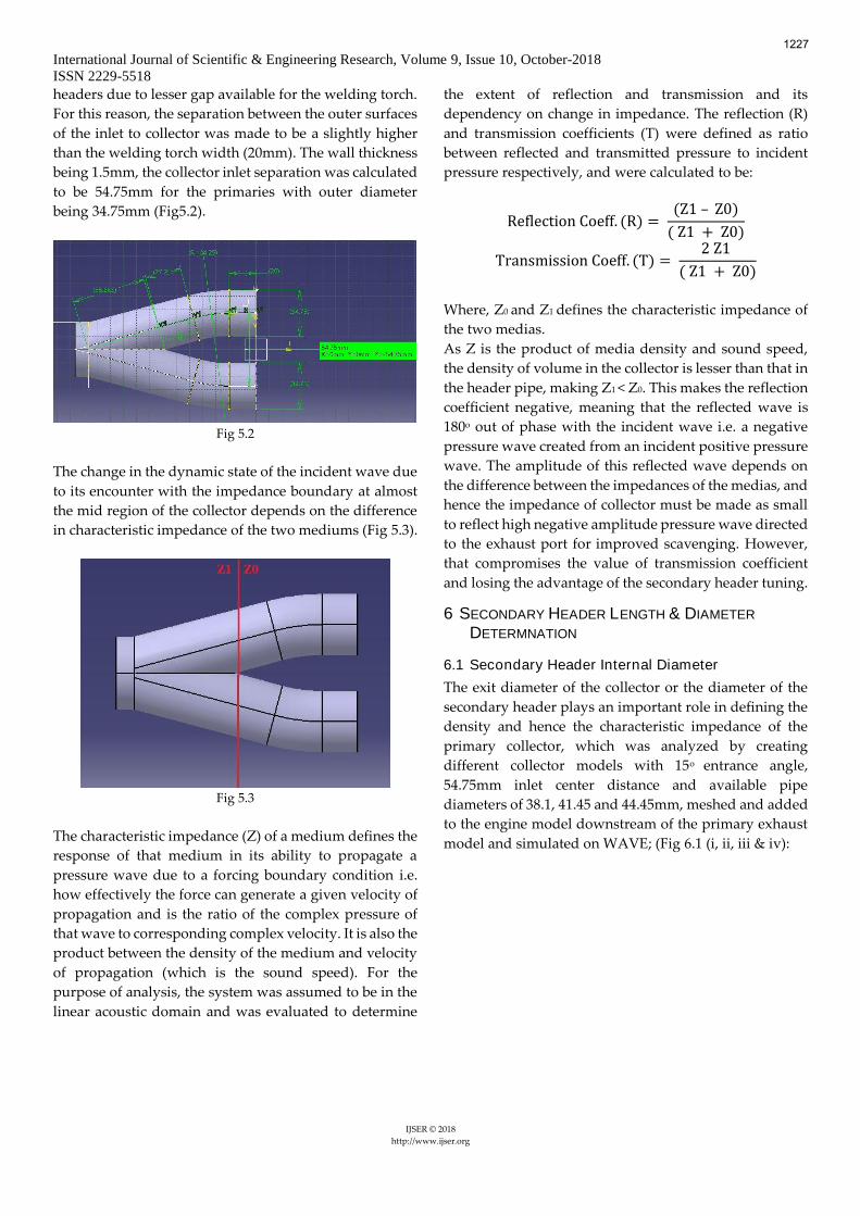
5.1 Best-fit Collector for High Performance Engines
Two categories of collectors were studied, namely
parallel and merge collectors. Having the same entry
angle of primary pipes into the collector, the parallel
collectors offers a sudden increase in area causing adverse
pressure gradient for the gases leading to their separation
from boundary layer and can sometimes create flow
reversal at low rpms. This phenomenon influences the
gas entering from the oppositely paired header into the
collector restricting its flow and causes mixing. It also
diminishes the influence of header tuning while making
the system unpredictable and insensitive with generation
of back pressure.
Conversely, a merge collector has an entrance cone (or
goilet) which is the outcome of the primary pipes
converging, creating more smoother transition into the
higher cross-section area region of the collector [1,7,8].
(Fig5.1(i & ii)) shows 4-1 parallel and merge collector
designs:
Parallel Collector – Fig 5.1 (i)
Merge Collectors – Fig 5.1 (ii)
The collector design has a great impact on exhaust gas
flow and header tuning, which is why a merge collector
of 15o entrance angle was designed.
The collector inlet center separation must be small
enough to allow for steady transition and to occupy less
space. Moreover, difficulty in assembly and welding
arises at the mating interface of the two converging
1226
International Journal of Scientific & Engineering Research, Volume 9, Issue 10, October-2018
ISSN 2229-5518
IJSER © 2018
http://www.ijser.org
headers due to lesser gap available for the welding torch.
For this reason, the separation between the outer surfaces
of the inlet to collector was made to be a slightly higher
than the welding torch width (20mm). The wall thickness
being 1.5mm, the collector inlet separation was calculated
to be 54.75mm for the primaries with outer diameter
being 34.75mm (Fig5.2).
Fig 5.2
The change in the dynamic state of the incident wave due
to its encounter with the impedance boundary at almost
the mid region of the collector depends on the difference
in characteristic impedance of the two mediums (Fig 5.3).
Fig 5.3
The characteristic impedance (Z) of a medium defines the
response of that medium in its ability to propagate a
pressure wave due to a forcing boundary condition i.e.
how effectively the force can generate a given velocity of
propagation and is the ratio of the complex pressure of
that wave to corresponding complex velocity. It is also the
product between the density of the medium and velocity
of propagation (which is the sound speed). For the
purpose of analysis, the system was assumed to be in the
linear acoustic domain and was evaluated to determine
the extent of reflection and transmission and its
dependency on change in impedance. The reflection (R)
and transmission coefficients (T) were defined as ratio
between reflected and transmitted pressure to incident
pressure respectively, and were calculated to be:
Reflection Coeff. (R) = (Z1 – Z0)
( Z1 + Z0)
Transmission Coeff. (T) = 2 Z1
( Z1 + Z0)
Where, Z0 and Z1 defines the characteristic impedance of
the two medias.
As Z is the product of media density and sound speed,
the density of volume in the collector is lesser than that in
the header pipe, making Z1 < Z0. This makes the reflection
coefficient negative, meaning that the reflected wave is
180o out of phase with the incident wave i.e. a negative
pressure wave created from an incident positive pressure
wave. The amplitude of this reflected wave depends on
the difference between the impedances of the medias, and
hence the impedance of collector must be made as small
to reflect high negative amplitude pressure wave directed
to the exhaust port for improved scavenging. However,
that compromises the value of transmission coefficient
and losing the advantage of the secondary header tuning.
6 SECONDARY HEADER LENGTH & DIAMETER
DETERMNATION
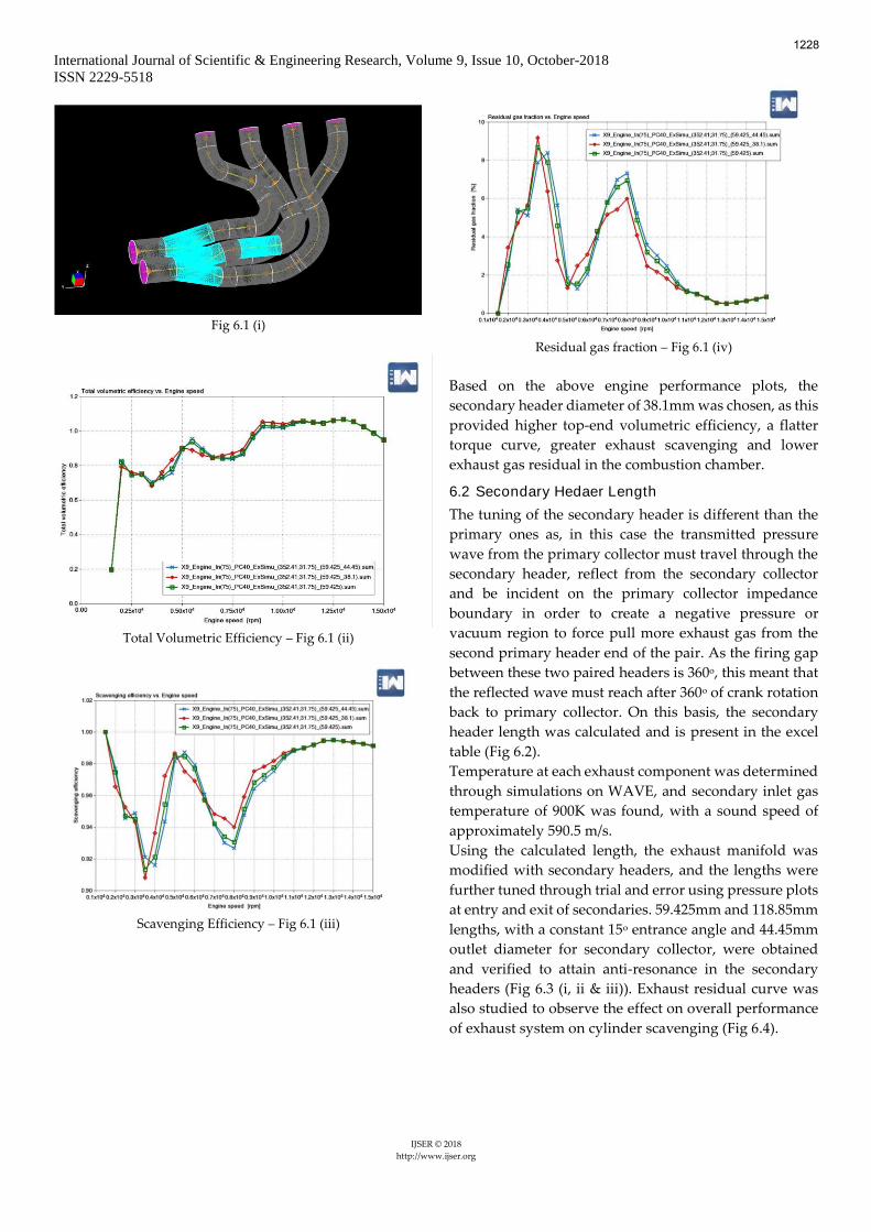
6.1 Secondary Header Internal Diameter
The exit diameter of the collector or the diameter of the
secondary header plays an important role in defining the
density and hence the characteristic impedance of the
primary collector, which was analyzed by creating
different collector models with 15o entrance angle,
54.75mm inlet center distance and available pipe
diameters of 38.1, 41.45 and 44.45mm, meshed and added
to the engine model downstream of the primary exhaust
model and simulated on WAVE; (Fig 6.1 (i, ii, iii & iv):
1227
International Journal of Scientific & Engineering Research, Volume 9, Issue 10, October-2018
ISSN 2229-5518
IJSER © 2018
http://www.ijser.org
Fig 6.1 (i)
Total Volumetric Efficiency – Fig 6.1 (ii)
Scavenging Efficiency – Fig 6.1 (iii)
Residual gas fraction – Fig 6.1 (iv)
Based on the above engine performance plots, the
secondary header diameter of 38.1mm was chosen, as this
provided higher top-end volumetric efficiency, a flatter
torque curve, greater exhaust scavenging and lower
exhaust gas residual in the combustion chamber.
6.2 Secondary Hedaer Length
The tuning of the secondary header is different than the
primary ones as, in this case the transmitted pressure
wave from the primary collector must travel through the
secondary header, reflect from the secondary collector
and be incident on the primary collector impedance
boundary in order to create a negative pressure or
vacuum region to force pull more exhaust gas from the
second primary header end of the pair. As the firing gap
between these two paired headers is 360o, this meant that
the reflected wave must reach after 360o of crank rotation
back to primary collector. On this basis, the secondary
header length was calculated and is present in the excel
table (Fig 6.2).
Temperature at each exhaust component was determined
through simulations on WAVE, and secondary inlet gas
temperature of 900K was found, with a sound speed of
approximately 590.5 m/s.
Using the calculated length, the exhaust manifold was
modified with secondary headers, and the lengths were
further tuned through trial and error using pressure plots
at entry and exit of secondaries. 59.425mm and 118.85mm
lengths, with a constant 15o entrance angle and 44.45mm
outlet diameter for secondary collector, were obtained
and verified to attain anti-resonance in the secondary
headers (Fig 6.3 (i, ii & iii)). Exhaust residual curve was
also studied to observe the effect on overall performance
of exhaust system on cylinder scavenging (Fig 6.4).
1228
International Journal of Scientific & Engineering Research, Volume 9, Issue 10, October-2018
ISSN 2229-5518
IJSER © 2018
http://www.ijser.org
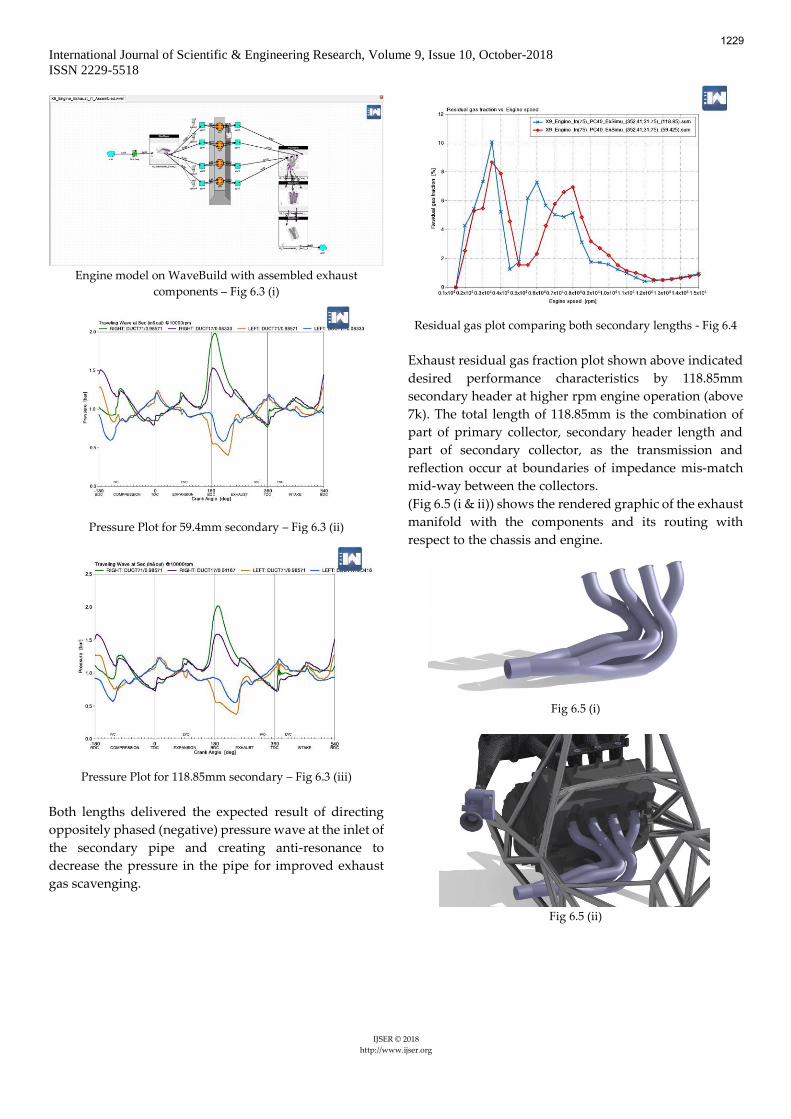
Engine model on WaveBuild with assembled exhaust
components – Fig 6.3 (i)
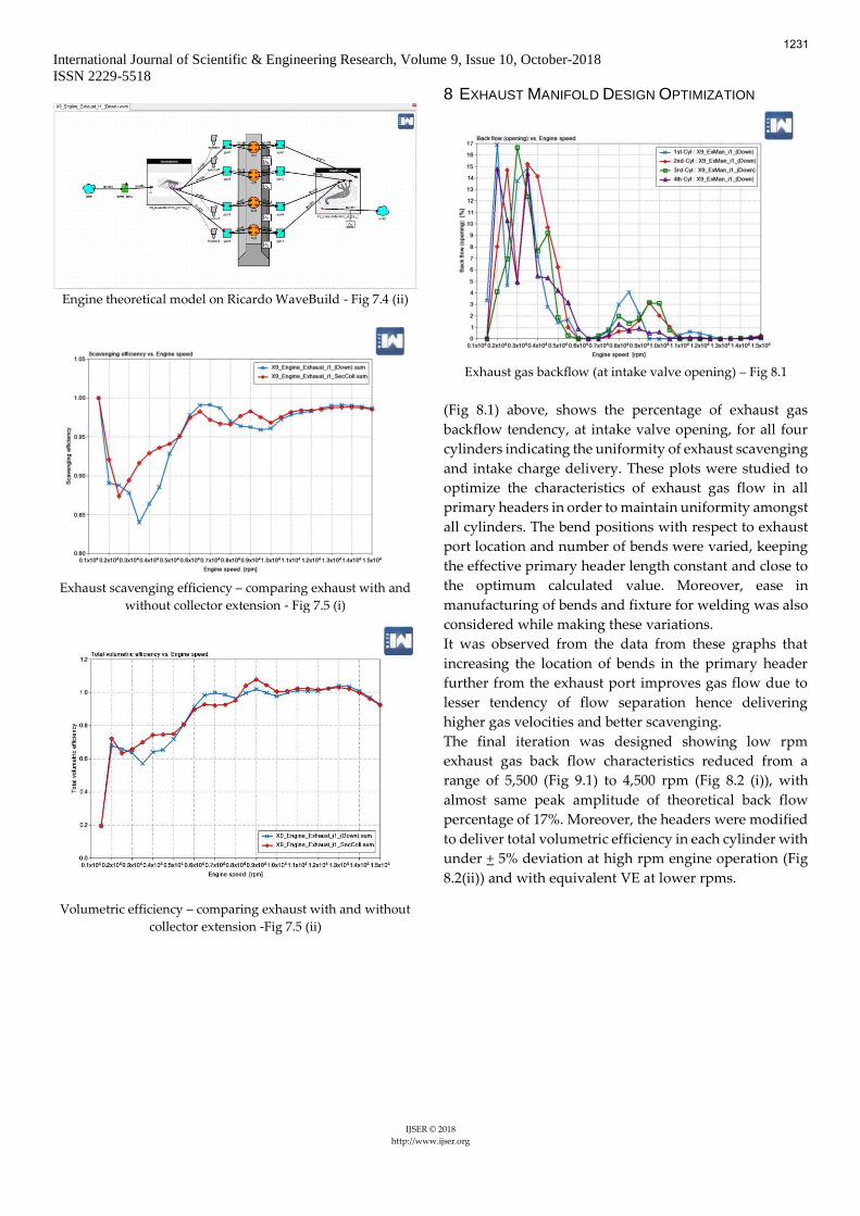
Pressure Plot for 59.4mm secondary – Fig 6.3 (ii)
Pressure Plot for 118.85mm secondary – Fig 6.3 (iii)
Both lengths delivered the expected result of directing
oppositely phased (negative) pressure wave at the inlet of
the secondary pipe and creating anti-resonance to
decrease the pressure in the pipe for improved exhaust
gas scavenging.
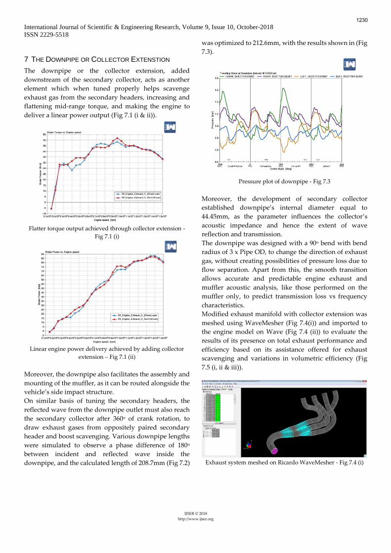
Residual gas plot comparing both secondary lengths - Fig 6.4
Exhaust residual gas fraction plot shown above indicated
desired performance characteristics by 118.85mm
secondary header at higher rpm engine operation (above
7k). The total length of 118.85mm is the combination of
part of primary collector, secondary header length and
part of secondary collector, as the transmission and
reflection occur at boundaries of impedance mis-match
mid-way between the collectors.
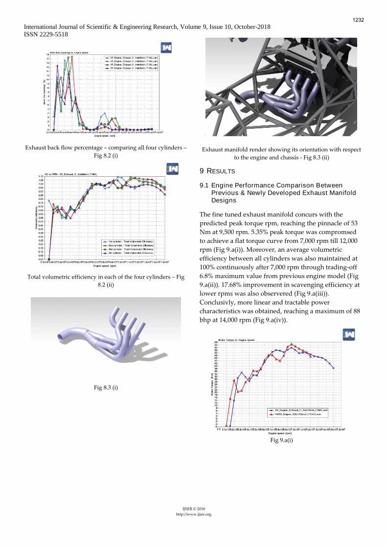
(Fig 6.5 (i & ii)) shows the rendered graphic of the exhaust
manifold with the components and its routing with
respect to the chassis and engine.
Fig 6.5 (i)
Fig 6.5 (ii)
1229
International Journal of Scientific & Engineering Research, Volume 9, Issue 10, October-2018
ISSN 2229-5518
IJSER © 2018
http://www.ijser.org
7 THE DOWNPIPE OR COLLECTOR EXTENSTION
The downpipe or the collector extension, added
downstream of the secondary collector, acts as another
element which when tuned properly helps scavenge
exhaust gas from the secondary headers, increasing and
flattening mid-range torque, and making the engine to
deliver a linear power output (Fig 7.1 (i & ii)).
Flatter torque output achieved through collector extension -
Fig 7.1 (i)
Linear engine power delivery achieved by adding collector
extension – Fig 7.1 (ii)
Moreover, the downpipe also facilitates the assembly and
mounting of the muffler, as it can be routed alongside the
vehicle’s side impact structure.
On similar basis of tuning the secondary headers, the
reflected wave from the downpipe outlet must also reach
the secondary collector after 360o of crank rotation, to
draw exhaust gases from oppositely paired secondary
header and boost scavenging. Various downpipe lengths
were simulated to observe a phase difference of 180o
between incident and reflected wave inside the
downpipe, and the calculated length of 208.7mm (Fig 7.2)
was optimized to 212.6mm, with the results shown in (Fig
7.3).
Pressure plot of downpipe - Fig 7.3
Moreover, the development of secondary collector
established downpipe’s internal diameter equal to
44.45mm, as the parameter influences the collector’s
acoustic impedance and hence the extent of wave
reflection and transmission.
The downpipe was designed with a 90o bend with bend
radius of 3 x Pipe OD, to change the direction of exhaust
gas, without creating possibilities of pressure loss due to
flow separation. Apart from this, the smooth transition
allows accurate and predictable engine exhaust and
muffler acoustic analysis, like those performed on the
muffler only, to predict transmission loss vs frequency
characteristics.
Modified exhaust manifold with collector extension was
meshed using WaveMesher (Fig 7.4(i)) and imported to
the engine model on Wave (Fig 7.4 (ii)) to evaluate the
results of its presence on total exhaust performance and
efficiency based on its assistance offered for exhaust
scavenging and variations in volumetric efficiency (Fig
7.5 (i, ii & iii)).
Exhaust system meshed on Ricardo WaveMesher - Fig 7.4 (i)
1230
International Journal of Scientific & Engineering Research, Volume 9, Issue 10, October-2018
ISSN 2229-5518
IJSER © 2018
http://www.ijser.org
Engine theoretical model on Ricardo WaveBuild - Fig 7.4 (ii)
Exhaust scavenging efficiency – comparing exhaust with and
without collector extension - Fig 7.5 (i)
Volumetric efficiency – comparing exhaust with and without
collector extension -Fig 7.5 (ii)
8 EXHAUST MANIFOLD DESIGN OPTIMIZATION
Exhaust gas backflow (at intake valve opening) – Fig 8.1
(Fig 8.1) above, shows the percentage of exhaust gas
backflow tendency, at intake valve opening, for all four
cylinders indicating the uniformity of exhaust scavenging
and intake charge delivery. These plots were studied to
optimize the characteristics of exhaust gas flow in all
primary headers in order to maintain uniformity amongst
all cylinders. The bend positions with respect to exhaust
port location and number of bends were varied, keeping
the effective primary header length constant and close to
the optimum calculated value. Moreover, ease in
manufacturing of bends and fixture for welding was also
considered while making these variations.
It was observed from the data from these graphs that
increasing the location of bends in the primary header
further from the exhaust port improves gas flow due to
lesser tendency of flow separation hence delivering
higher gas velocities and better scavenging.
The final iteration was designed showing low rpm
exhaust gas back flow characteristics reduced from a
range of 5,500 (Fig 9.1) to 4,500 rpm (Fig 8.2 (i)), with
almost same peak amplitude of theoretical back flow
percentage of 17%. Moreover, the headers were modified
to deliver total volumetric efficiency in each cylinder with
under + 5% deviation at high rpm engine operation (Fig
8.2(ii)) and with equivalent VE at lower rpms.
1231
International Journal of Scientific & Engineering Research, Volume 9, Issue 10, October-2018
ISSN 2229-5518
IJSER © 2018
http://www.ijser.org
Exhaust back flow percentage – comparing all four cylinders –
Fig 8.2 (i)
Total volumetric efficiency in each of the four cylinders – Fig
8.2 (ii)
Fig 8.3 (i)
Exhaust manifold render showing its orientation with respect
to the engine and chassis - Fig 8.3 (ii)
9 RESULTS
9.1 Engine Performance Comparison Between Previous & Newly Developed Exhaust Manifold Designs
The fine tuned exhaust manifold concurs with the
predicted peak torque rpm, reaching the pinnacle of 53
Nm at 9,500 rpm. 5.35% peak torque was compromsed
to achieve a flat torque curve from 7,000 rpm till 12,000
rpm (Fig 9.a(i)). Moreover, an average volumetric
efficiency between all cylinders was also maintained at
100% continuously after 7,000 rpm through trading-off
6.8% maximum value from previous engine model (Fig
9.a(ii)). 17.68% improvement in scavenging efficiency at
lower rpms was also observered (Fig 9.a(iii)).
Conclusivly, more linear and tractable power
characteristics was obtained, reaching a maximum of 88
bhp at 14,000 rpm (Fig 9.a(iv)).
Fig 9.a(i)
1232
International Journal of Scientific & Engineering Research, Volume 9, Issue 10, October-2018
ISSN 2229-5518
IJSER © 2018
http://www.ijser.org
Fig 9.a(ii)
Fig 9.a(iii)
Fig 9.a(iv)
Primary Header Effective Length Calculation – Fig 4.4
1233

International Journal of Scientific & Engineering Research, Volume 9, Issue 10, October-2018
ISSN 2229-5518
IJSER © 2018
http://www.ijser.org
Fig 4.10
Secondary Header Effective Length Calculation – Fig 6.2
Downpipe or Collector Extension Effective Length Calculation – Fig 7.2
1234

International Journal of Scientific & Engineering Research, Volume 9, Issue 10, October-2018
ISSN 2229-5518
IJSER © 2018
http://www.ijser.org
10 REFERENCES
[1] Exhaust Science Demystified
(http://www.superchevy.com/how-to/exhaust/0505phr-
exh/)
[2] A New Simple Friction Model for S. I. Engine -
Emiliano Pipitone (SAE Technical Paper, 2009-01-1984)
[3] Nature of Heat Release Rate in an Engine - IITD
(web.iitd.ac.in/~pmvs/courses/mel713/mel713-20.ppt)
[4] Willard. W. Pulkrabeck (engineering-fundamentals-
of-the-internal-combustion-engine)
[5] Open and Closed Organ Pipes
(https://newt.phys.unsw.edu.au/jw/flutes.v.clarinets.htm
l)
[6] Pipes and Harmonics
(https://newt.phys.unsw.edu.au/jw/pipes.html)
[7] Difference between shorty and full length headers
(http://garage.grumpysperformance.com/index.php?thre
ads/differance-between-shorty-and-full-length-
headers.1303/)
[8] Jack Burns – The Sultan of Stainless
(https://www.hotrod.com/articles/0310phr-jack-burns-
exhaust-manifold-header-tech/)
[9] Exhaust System Technology (http://www.epi-
eng.com/piston_engine_technology/exhaust_system_tec
hnology.htm)
1235