Embed Size (px)
Citation preview
RP158
ENGINE-IGNITION SHIELDING FOR RADIO RECEPTIONIN AIRCRAFT
By H. Diamond and F. G. Gardner
ABSTRACT
The use of highly sensitive receiving equipment on aircraft has made the prob-lem of airplane engine ignition shielding an important one. Ignition shieldingconsists of so confining the electrical fields of the ignition system that no interfering
signal can be set up in the radio receiving circuits. The problem in ignition
shielding is chiefly in the electrical and mechanical design of the arrangement for
shielding, it being much more difficult to secure an assembly which will not ad-versely affect the engine-ignition system than to obtain complete freedom frominterference for the radio equipment.The bureau has been in active cooperation with airplane-engine, magneto,
spark-plug, and cable manufacturers in an effort to develop a safe method foreffecting this shielding and to make the necessary equipment available commer-cially. As a result of this cooperation shielding assemblies may now be purchasedfor use on all Wright and Pratt-Whitney airplane engines. A metallic ignition
manifold is employed with high-tension cable drawn through it in the usual way.The leads from the manifold to the spark plugs and the groups of leads from themanifold to the magneto outlets are inclosed in liquid-proof flexible aluminumtubing with copper braid on the outside to insure effective shielding. Eachflexible tubing is suitably fitted to the ignition manifold and to the magnetos orspark plugs, as the case may be. The magnetos are provided with covers whichcompletely inclose the distributor blocks. A single outlet permits the use of anelbow fitting for connection to the large flexible metal tubing. This elbow fitting
differs for different types of engines. Outlets are provided in the elbows for thebooster and ground leads. The spark plugs are of a type in which the shield is
an integral part and are provided with elbows for connection to the smallerflexible metal tubing. The ignition switch is totally inclosed in a metal cover, thebooster magneto is also covered, and the leads from the magnetos to the ignitionswitch and booster magneto are inclosed in flexible metal tubing. The completeassembly insures electrical safety; mechanical sturdiness; liquid proofing ofmagnetos, spark plugs, and ignition cable; and ease of installation and of servicing.
CONTENTSPage
I. Introduction 415II . Requirements for a practicable shielding assembly 416
III. Description of bureau's work 4171. Early shielding assemblies 4172. Improved shielding assembly, manifold type 420
IV. Bonding of aircraft—Shielding of auxiliary electrical apparatus 422V. Tests for practicability of shielding system 423
1. Test for shielding 4232. Test of complete assembly for sparkover 4243. Test for insulation resistance during and after exposure 4244. Test for corona 424
I. INTRODUCTION
The increasing use of radio reception on aircraft for weather andnavigational services has made the problem of airplane engine-ignition shielding of primary importance. To obtain full efficiency
of operation of the sensitive aircraft receiving sets now available, it
415
416 Bureau of Standards Journal of Research [V0L4.
is necessary to eliminate the intense electrical disturbances set upin the radio-receiving circuits by the engine-ignition system. Ignitionshielding consists of so confining the electrical fields of the ignitionsystem that no interfering signal can be induced in the radio circuits.
The care which must be taken in ignition shielding depends entirelyupon the ratio of the interfering signal of ignition x induced in thereceiving antenna to the radio signal required. This ratio is depend-ent upon the sensitivity of the receiving set employed, the type andlocation of the receiving antenna, and the frequency of the signal tobe received. The more sensitive the receiving set, the smaller is
the signal voltage required in the antenna for actuating whateverdevice may be connected in the receiver output. Since the voltageof the ignition interference is fixed for a given antenna, the inter-
ference-to-signal ratio is thus increased. On the other hand, assuminga fixed receiver sensitivity (hence, a fixed minimum useful receivedsignal) the interference-to-signal ratio will depend upon the lengthof receiving antenna and its position with respect to the interfering
source. Finally, since the source of disturbance consists essentially
of a group of spark transmitters of varying high frequencies, thehigher the frequency to which the receiving system is tuned, thegreater will be the interference-to-signal ratio.
Within the past two years it has become common practice to usea vertical pole antenna with a highly sensitive receiving set for recep-tion on aircraft. The requirements for ignition shielding have, there-
fore, become rigorous. To obtain effective shielding it becomesnecessary to inclose the entire electrical system of the engine ignition
in a high conductivity metallic shield. Therefore, the magnetosmust be provided with such metallic covers as will completely inclose
the distributing heads. The booster magneto must also be inclosed
in metal. All distributing wires must be covered with a metal tubeor braid. The spark plugs must be completely shielded. The boosterleads, the leads to the ignition switch, and the ignition switch itself,
must also be shielded.
II. REQUIREMENTS FOR A PRACTICABLE SHIELDINGASSEMBLY
The inclosure of the high voltage electrical system of the ignition
in a closely surrounding grounded metallic casing introduces certain
problems of electrical and mechanical design. It is much moredifficult to secure an arrangement which will not adversely affect theengine-ignition system than to obtain freedom from ignition inter-
ference for the radio equipment. The factors which enter into thedesign of a safe and practicable shielding assembly may well be stated
at this point.
1. Reliability of engine performance is the first consideration.
The shielding must be such as to prevent insulation breakdown of anyof the component parts of the ignition system. Full provision for the
protection of the component parts from the effects of oil, gasoline,
and water should be made. Mechanical protection of the ignition
cable and other parts is necessary.
1 Where the engine is unshielded.
B. S. Journal of Research, RP158
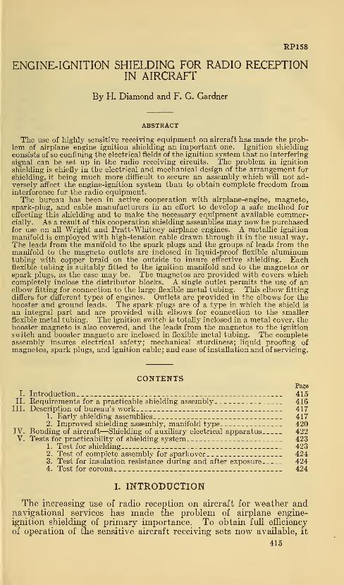
Figure 1.
—
Early shielding installation on Wright J-5airplane engine
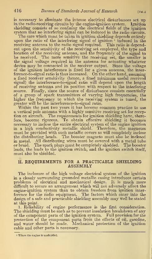
Figure 2.—Early type shielded spark plug
oiar7nn
d]
Airplane Engine Ignition Shielding 417
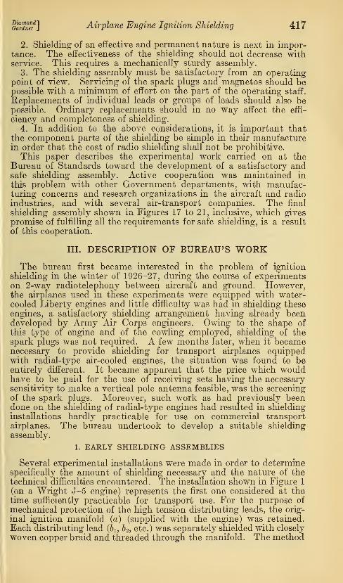
2. Shielding of an effective and permanent nature is next in impor-tance. The effectiveness of the shielding should not decrease withservice. This requires a mechanically sturdy assembly.
3. The shielding assembly must be satisfactory from an operatingpoint of view. Servicing of the spark plugs and magnetos should bepossible with a minimum of effort on the part of the operating staff.
Replacements of individual leads or groups of leads should also bepossible. Ordinary replacements should in no way affect the effi-
ciency and completeness of shielding.
4. In addition to the above considerations, it is important thatthe component parts of the shielding be simple in their manufacturein order that the cost of radio shielding shall not be prohibitive.
This paper describes the experimental work carried on at theBureau of Standards toward the development of a satisfactory andsafe shielding assembly. Active cooperation was maintained in
this problem with other Government departments, with manufac-turing concerns and research organizations in the aircraft and radioindustries, and with several air-transport companies. The final
shielding assembly shown in Figures 17 to 21, inclusive, which givespromise of fulfilling all the requirements for safe shielding, is a result
of this cooperation.
III. DESCRIPTION OF BUREAU'S WORKThe bureau first became interested in the problem of ignition
shielding in the winter of 1926-27, during the course of experimentson 2-way radiotelephony between aircraft and ground. However,the airplanes used in these experiments were equipped with water-cooled Liberty engines and little difficulty was had in shielding theseengines, a satisfactory shielding arrangement having already beendeveloped by Army Air Corps engineers. Owing to the shape of
this type of engine and of the cowling employed, shielding of thespark plugs was not required. A few months later, when it becamenecessary to provide shielding for transport airplanes equippedwith radial-type air-cooled engines, the situation was found to beentirely different. It became apparent that the price which wouldhave to be paid for the use of receiving sets having the necessarysensitivity to make a vertical pole antenna feasible, was the screeningof the spark plugs. Moreover, such work as had previously beendone on the shielding of radial-type engines had resulted in shielding
installations hardly practicable for use on commercial transportairplanes. The bureau undertook to develop a suitable shielding
assembly.
1. EARLY SHIELDING ASSEMBLIES
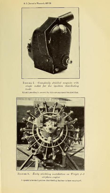
Several experimental installations were made in order to determinespecifically the amount of shielding necessary and the nature of thetechnical difficulties encountered. The installation shown in Figure 1
(on a Wright J-5 engine) represents the first one considered at thetime sufficiently practicable for transport use. For the purpose of
mechanical protection of the high tension distributing leads, the orig-
inal ignition manifold (a) (supplied with the engine) was retained.
Each distributing lead (bu b 2 , etc.) was separately shielded with closely
woven copper braid and threaded through the manifold. The method
418 Bureau of Standards Journal of Research [V01.4
of connecting the distributing leads to the shielded spark plugs (ci,c2 ,
etc.) may be seen in Figure 1 and in somewhat better detail in Figure 2.
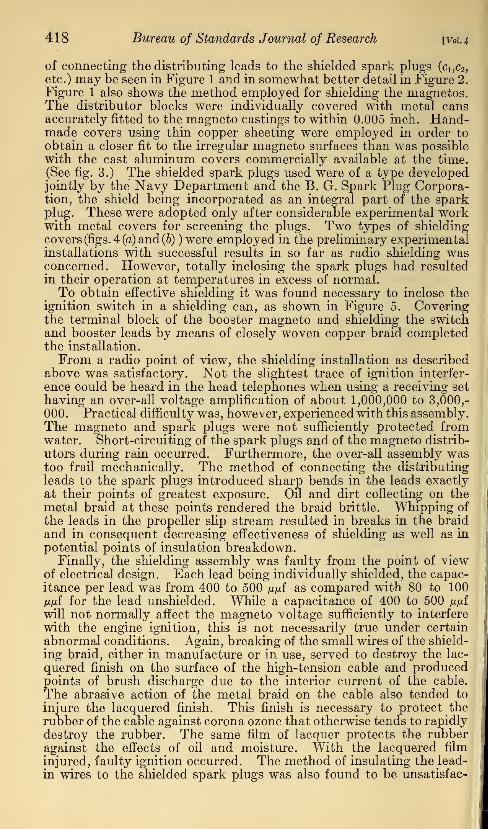
Figure 1 also shows the method employed for shielding the magnetos.The distributor blocks were individually covered with metal cansaccurately fitted to the magneto castings to within 0.005 inch. Hand-made covers using thin copper sheeting were employed in order to
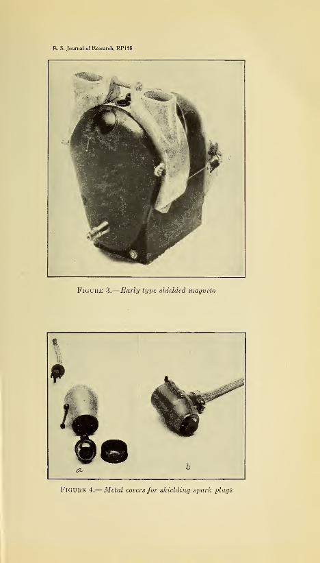
obtain a closer fit to the irregular magneto surfaces than was possiblewith the cast aluminum covers commercially available at the time.(See fig. 3.) The shielded spark plugs used were of a type developedjointly by the Navy Department and the B. G. Spark Plug Corpora-tion, the shield being incorporated as an integral part of the sparkplug. These were adopted only after considerable experimental workwith metal covers for screening the plugs. Two types of shielding
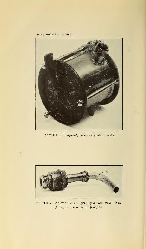
covers (figs. 4 (a) and (b) ) were employed in the preliminary experimentalinstallations with successful results in so far as radio shielding wasconcerned. However, totally inclosing the spark plugs had resultedin their operation at temperatures in excess of normal.To obtain effective shielding it was found necessary to inclose the
ignition switch in a shielding can, as shown in Figure 5. Coveringthe terminal block of the booster magneto and shielding the switchand booster leads by means of closely woven copper braid completedthe installation.
From a radio point of view, the shielding installation as describedabove was satisfactory. Not the slightest trace of ignition interfer-
ence could be heard in the head telephones when using a receiving set
having an over-all voltage amplification of about 1,000,000 to 3,000,-
000. Practical difficulty was, however, experienced with this assembly.The magneto and spark plugs were not sufficiently protected fromwater. Short-circuiting of the spark plugs and of the magneto distrib-
utors during rain occurred. Furthermore, the over-all assembly wastoo frail mechanically. The method of connecting the distributing
leads to the spark plugs introduced sharp bends in the leads exactly
at their points of greatest exposure. Oil and dirt collecting on the
metal braid at these points rendered the braid brittle. Whipping of
the leads in the propeller slip stream resulted in breaks in the braidand in consequent decreasing effectiveness of shielding as well as in
potential points of insulation breakdown.Finally, the shielding assembly was faulty from the point of view
of electrical design. Each lead being individually shielded, the capac-itance per lead was from 400 to 500 ju>uf as compared with 80 to 100jujuf for the lead unshielded. While a capacitance of 400 to 500 ii^i
will not normally affect the magneto voltage sufficiently to interfere
with the engine ignition, this is not necessarily true under certain
abnormal conditions. Again, breaking of the small wires of the shield-
ing braid, either in manufacture or in use, served to destroy the lac-
quered finish on the surface of the high-tension cable and producedpoints of brush discharge due to the interior current of the cable.
The abrasive action of the metal braid on the cable also tended to
injure the lacquered finish. This finish is necessary to protect the
rubber of the cable against corona ozone that otherwise tends to rapidly
destroy the rubber. The same film of lacquer protects the rubberagainst the effects of oil and moisture. With the lacquered film
injured, faulty ignition occurred. The method of insulating the lead-
in wires to the shielded spark plugs was also found to be unsatisfac-
B. S. Journal of Research, RPI58
*mm'' *'§' mmk
f- §.
*%*m
ws?
wL Jm
•^B
Figure 3.
—
Early type shielded magneto
Figure 4.-
—
Metal covers for shielding spark plugs
B. S. Journal of Research, RP158
Figure 5.
—
Completely shielded ignition switch
Figure 6.—Shielded spark plug provided with elbow
fitting to insure liquid proofing
B. S. Journal of Research, RP158
Figure 7.
—
Completely shielded magneto with
single outlet for the ignition distributing
leads
Liquid proofing is assure:} by this arrangement for shielding.
Figure 8.
—
Early shielding installation on Wright J-5airplane engine
A special shielded ignition distributing harness is here employed.
B. S. Journal of Research, RP158
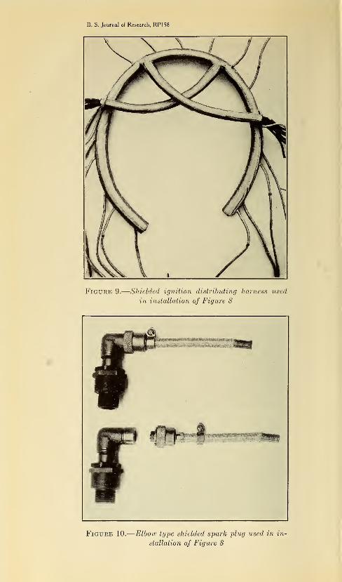
Figure 9.
—
Shielded ignition distributing harness used
in installation of Figure 8
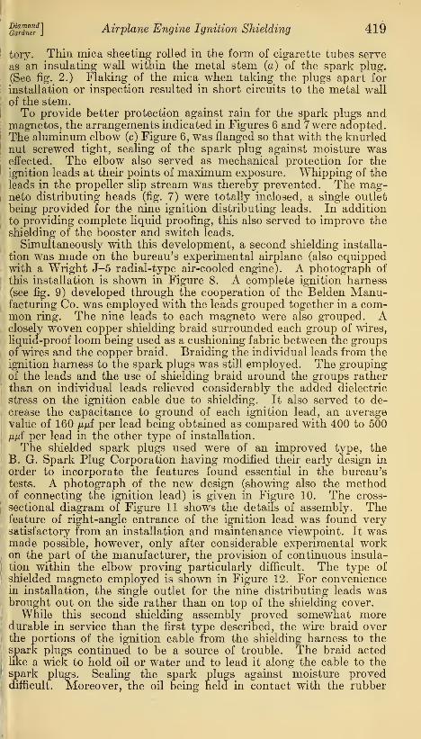
Figure 10.
—
Elbow type shielded spark plug used in in-
stallation of Figure 8
aSS?] Airplane Engine Ignition Shielding 419
tory. Thin mica sheeting rolled in the form of cigarette tubes serve
as an insulating wall within the metal stem (a) of the spark plug.
(See fig. 2.) Flaking of the mica when taking the plugs apart for
installation or inspection resulted in short circuits to the metal wall
of the stem.To provide better protection against rain for the spark plugs and
magnetos, the arrangements indicated in Figures 6 and 7 were adopted.The aluminum elbow (c) Figure 6, was flanged so that with the knurlednut screwed tight, sealing of the spark plug against moisture waseffected. The elbow also served as mechanical protection for theignition leads at their points of maximum exposure. Whipping of theleads in the propeller slip stream was thereby prevented. The mag-neto distributing heads (fig. 7) were totally inclosed, a single outlet
being provided for the nine ignition distributing leads. In addition
to providing complete liquid proofing, this also served to improve theshielding of the booster and switch leads.
Simultaneously with this development, a second shielding installa-
tion was made on the bureau's experimental airplane (also equippedwith a Wright J-5 radial-type air-cooled engine). A photograph of
this installation is shown in Figure 8. A complete ignition harness(see fig. 9) developed through the cooperation of the Belden Manu-facturing Co. was employed with the leads grouped together in a com-mon ring. The nine leads to each magneto were also grouped. Aclosely woven copper shielding braid surrounded each group of wires,
liquid-proof loom being used as a cushioning fabric between the groupsof wires and the copper braid. Braiding the individual leads from theignition harness to the spark plugs was still employed. The groupingof the leads and the use of shielding braid around the groups ratherthan on individual leads relieved considerably the added dielectric
stress on the ignition cable due to shielding. It also served to de-crease the capacitance to ground of each ignition lead, an averagevalue of 160 ppf per lead being obtained as compared with 400 to 500fxfii per lead in the other type of installation.
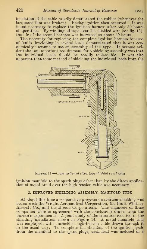
The shielded spark plugs used were of an improved type, theB. G. Spark Plug Corporation having modified their early design in
order to incorporate the features found essential in the bureau'stests. A photograph of the new design (showing also the methodof connecting the ignition lead) is given in Figure 10. The cross-
sectional diagram of Figure 11 shows the details of assembly. Thefeature of right-angle entrance of the ignition lead was found verysatisfactory from an installation and maintenance viewpoint. It wasmade possible, however, only after considerable experimental workon the part of the manufacturer, the provision of continuous insula-
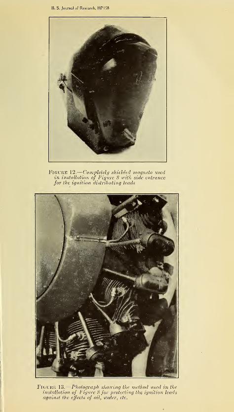
tion within the elbow proving particularly difficult. The type of
shielded magneto employed is shown in Figure 12. For conveniencein installation, the single outlet for the nine distributing leads wasbrought out on the side rather than on top of the shielding cover.
While this second shielding assembly proved somewhat morej
durable in service than the first type described, the wire braid over
I
the portions of the ignition cable from the shielding harness to the
I
spark plugs continued to be a source of trouble. The braid acted
I
like a wick to hold oil or water and to lead it along the cable to the
!spark plugs. Sealing the spark plugs against moisture proved
I difficult. Moreover, the oil being held in contact with the rubber
420 Bureau of Standards Journal of Research [Vol. 4
insulation of the cable rapidly deteriorated the rubber (whenever thelacquered film was broken). Faulty ignition then occurred. It wasfound necessary to replace the ignition harness after only 30 hoursof operation. By winding oil tape over the shielded wire (see fig. 13),the life of the second harness was increased to about 50 hours.The necessity for replacing the complete ignition harness because
of faults developing in several leads demonstrated that it was eco-nomically unsound to use an assembly of this type. It became evi-
dent that an important requirement for a shielding assembly was thatthe individual leads should be readily replaceable. It was also
apparent that some method of shielding the individual leads from the
Figure 11.
—
Cross section of elbow type shielded spark plug
ignition manifold to the spark plugs other than by the direct applica-
tion of metal braid over the high-tension cable was necessary.
2. IMPROVED SHIELDING ASSEMBLY, MANIFOLD TYPE
At about this time a cooperative program on ignition shielding wasbegun with the Wright Aeronautical Corporation, the Pratt-WhitneyAircraft Co., and the Breeze Corporations. The engineers of these
companies were in agreement with the conclusions drawn from the
bureau's experiments. A joint study of the situation resulted in the
shielding installation shown in Figure 14. A metal manifold ring
was employed, with unshielded high-tension cable drawn through it
in the usual way. To complete the shielding of the ignition leads
from the manifold to the spark plugs, each lead was inclosed in a
B. S. Journal of Research, RPI58
Figure 12.
—
Completely shielded magneto usedin installation of Figure 8 with side entrancefor the ignition distributing leads
Figure 13.
—
Photograph showing the method used in the
installation of Figure 8 for protecting the ignition leadsagainst the effects of oil, water, etc.
B. S. Journal of Research, RP158
rai^V^SK^^^I ^ES^I
l- «8r ^HEiUMBK^H
'- '*''!:"
BbBm^^H
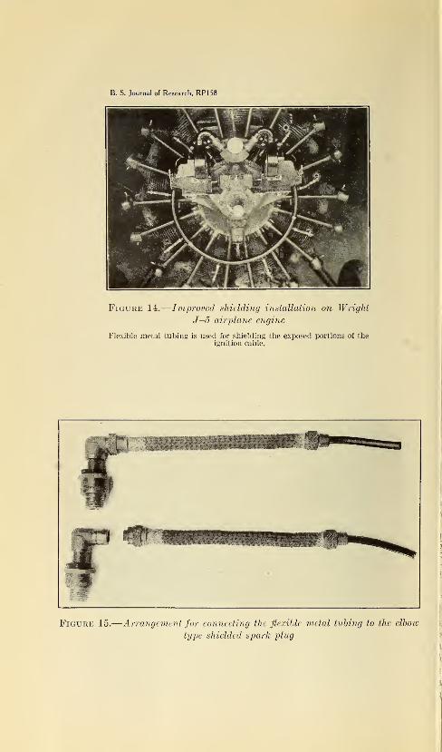
Figure 14.
—
Improved shielding installation on Wright
J—5 airplane engine
Flexible metal tubing is used for shielding the exposed portions of theignition cable.
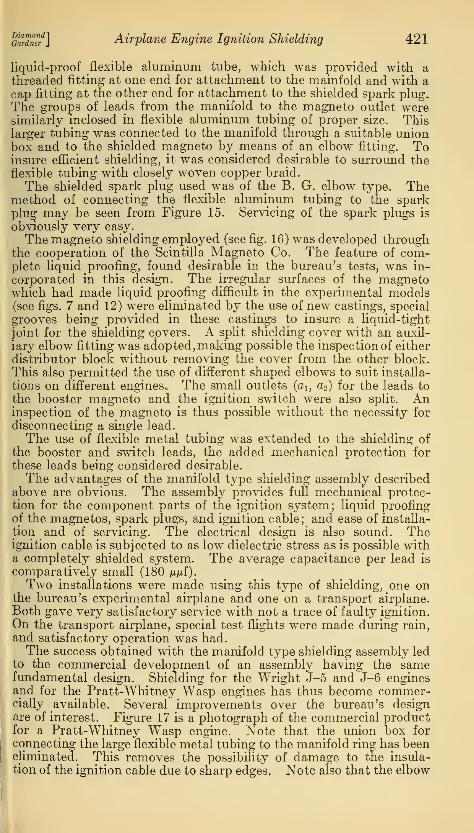
Figure 15.
—
Arrangement for connecting the flexible metal tubing to the elbow
type shielded spark plug
DiamondGardner Airplane Engine Ignition Shielding 421
liquid-proof flexible aluminum tube, which was provided with athreaded fitting at one end for attachment to the mainfold and with acap fitting at the other end for attachment to the shielded spark plug.
The groups of leads from the manifold to the magneto outlet weresimilarly inclosed in flexible aluminum tubing of proper size. Thislarger tubing was connected to the manifold through a suitable unionbox and to the shielded magneto by means of an elbow fitting. Toinsure efficient shielding, it was considered desirable to surround the
flexible tubing with closely woven copper braid.
The shielded spark plug used was of the B. G. elbow type. Themethod of connecting the flexible aluminum tubing to the sparkplug may be seen from Figure 15. Servicing of the spark plugs is
obviously very easy.
The magneto shielding employed (see fig. 16) was developed throughthe cooperation of the Scintilla Magneto Co. The feature of com-plete liquid proofing, found desirable in the bureau's tests, was in-
corporated in this design. The irregular surfaces of the magnetowhich had made liquid proofing difficult in the experimental models(see figs. 7 and 12) were eliminated by the use of new castings, special
grooves being provided in these castings to insure a liquid-tight
joint for the shielding covers. A split shielding cover with an auxil-
iary elbow fitting was adopted, making possible the inspection of either
distributor block without removing the cover from the other block.This also permitted the use of different shaped elbows to suit installa-
tions on different engines* The small outlets (a1} a2 ) for the leads to
the booster magneto and the ignition switch were also split. Aninspection of the magneto is thus possible without the necessity for
disconnecting a single lead.
The use of flexible metal tubing was extended to the shielding of
the booster and switch leads, the added mechanical protection for
these leads being considered desirable.
The advantages of the manifold type shielding assembly describedabove are obvious. The assembly provides full mechanical protec-tion for the component parts of the ignition system; liquid proofingof the magnetos, spark plugs, and ignition cable; and ease of installa-
tion and of servicing. The electrical design is also sound. Theignition cable is subjected to as low dielectric stress as is possible witha completely shielded system. The average capacitance per lead is
comparatively small (180 tifii).
Two installations were made using this type of shielding, one onthe bureau's experimental airplane and one on a transport airplane.
Both gave very satisfactory service with not a trace of faulty ignition.
On the transport airplane, special test nights were made during rain,
and satisfactory operation was had.The success obtained with the manifold type shielding assembly led
to the commercial development of an assembly having the samefundamental design. Shielding for the Wright J-5 and J-6 enginesand for the Pratt-Whitney Wasp engines has thus become commer-cially available. Several improvements over the bureau's designare of interest. Figure 17 is a photograph of the commercial productfor a Pratt-Whitney Wasp engine. Note that the union box for
connecting the large flexible metal tubing to the manifold ring has beeneliminated. This removes the possibility of damage to the insula-
tion of the ignition cable due to sharp edges, Note also that the elbow
422 Bureau of Standards Journal of Research [Vol. 4
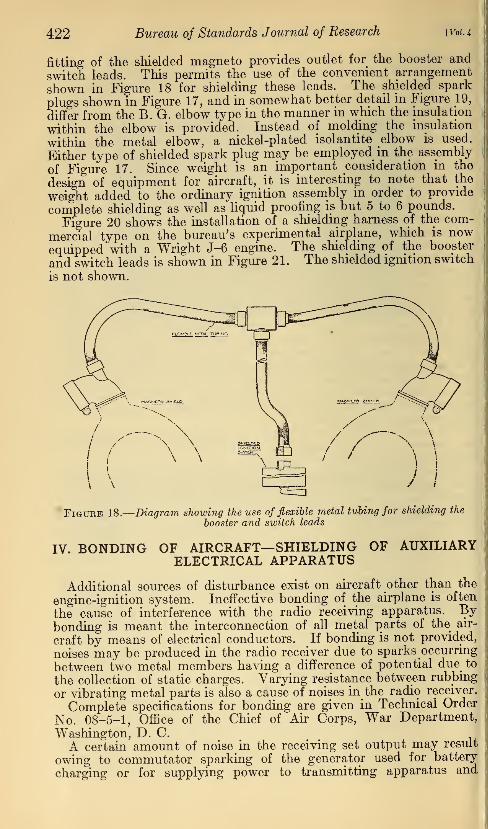
fitting of the shielded magneto provides outlet for the booster and
switch leads. This permits the use of the convenient arrangement
shown in Figure 18 for shielding these leads. The shielded spark
plugs shown in Figure 17, and in somewhat better detail in Figure 19,
differ from the B. G. elbow type in the manner in which the insulation
within the elbow is provided. Instead of molding the insulation
within the metal elbow, a nickel-plated isolantite elbow is used.
Either type of shielded spark plug may be employed in the assembly
of Figure 17. Since weight is an important consideration in the
design of equipment for aircraft, it is interesting to note that the
weight added to the ordinary ignition assembly in order to provide
complete shielding as well as liquid proofing is but 5 to 6 pounds.
Figure 20 shows the installation of a shielding harness of the com-
mercial type on the bureau's experimental airplane, which is nowequipped with a Wright J-6 engine. The shielding of the booster
and switch leads is shown in Figure 21. The shielded ignition switch
is not shown.
Figure 18.
—
Diagram showing the use of flexible metal tubing for shielding the
booster and switch leads
IV. BONDING OF AIRCRAFT—SHIELDING OF AUXILIARYELECTRICAL APPARATUS
Additional sources of disturbance exist on aircraft other than the
engine-ignition system. Ineffective bonding of the airplane is often
the cause of interference with the radio receiving apparatus. Bybonding is meant the interconnection of all metal parts of the air-
craft by means of electrical conductors. If bonding is not provided,
noises may be produced in the radio receiver due to sparks occurring
between two metal members having a difference of potential due to
the collection of static charges. Varying resistance between rubbing
or vibrating metal parts is also a cause of noises in the radio receiver.
Complete specifications for bonding are given in Technical Order
No. 08-5-1, Office of the Chief of Air Corps, War Department,
Washington, D. C.
A certain amount of noise in the receiving set output may result
owing to commutator sparking of the generator used for battery
charging or for supplying power to transmitting apparatus and
B. S. Journal of Research, RP158
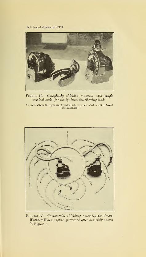
Figure 16.
—
Completely shielded magneto with single
vertical outlet for the ignition distributing leads
A special elbow fitting is employed which may be varied to suit differentinstallations.
Figure 17.
—
Commercial shielding assembly for Pratt-
Whitney Wasp engine, patterned after assembly shownin Figure 14
B. S. Journal of Research, RP158
lo^vm-;,,,.
.
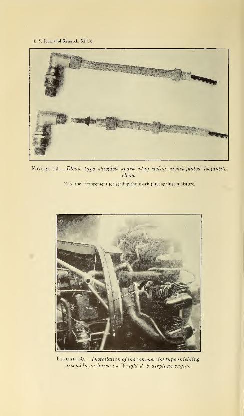
Figure 19.
—
Elbow type shielded spark plug using nickel-plated isolantite
elbow
Note the arrangement for sealing the spark plug against moisture.
Figure 20.
—
Installation of the commercial type shielding
assembly on bureau's Wright J-6 airplane engine
B. S. Journal of Research, RP158
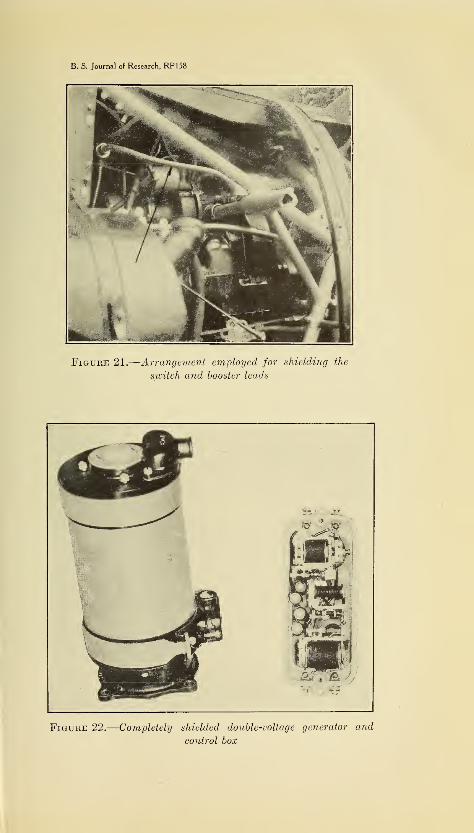
Figure 21.
—
Arrangement employed for shielding the
switch and booster leads
Figure 22.
—
Completely shielded double-voltage generator and
control box
GaTdnS4
]Airplane Engine Ignition Shielding 423
receiving apparatus on aircraft. The sparking of the vibrating
type voltage regulators used with these generators is an additional
source of disturbance. Wherever possible, any piece of apparatus in
which a spark occurs should be completely inclosed in metal. Aphotograph of a shielded generator and control box is given in Figure
22. Completely inclosing the generator is, however, not sufficient,
since the disturbance may be carried by way of the leads from the
generator. This requires shielding of all the leads. If the generator
serves as a source of supply for the receiving equipment, suitable
filter units must be employed in addition, to keep the commutatornoises out of the radio receiver.
Further information on this subject may be obtained by reference to
mimeographed notes 2 on the " Minutes of conference on airplane
engine ignition shielding held at the Bureau of Standards, June 11,1929." This conference was called by the Bureau of Standards in
response to a number of requests from representatives of the aircraft
and radio industries. The purpose of the conference was fourfold:
1. To coordinate the experience and knowledge of the numerousorganizations interested in this problem.
2. To formulate the requirements essential to safe shielding.
3. To stimulate the standardization of shielding assembly practice.
4. To set up standard tests whereby the mechanical, electrical, andradio efficiency of a given shielding installation may be determined.
V. TESTS FOR PRACTICABILITY OF SHIELDING SYSTEM
It is to be emphasized that the manifold type of shielding assemblydescribed in this paper is not necessarily the only practicable solution
of the problem of ignition shielding. The problem may be approachedfrom numerous angles, so that other solutions entirely as practicable
are possible. For this reason a set of standard tests was tentatively
adopted at the conference on ignition shielding whereby the prac-ticability of any shielding assembly, no matter of what type, ma}7 bedetermined. These tests are outlined below. The usefulness of thesetests is now under investigation.
1. TEST FOR SHIELDING
The best test for radio shielding is the actual use of the shieldingassembly mounted on the airplane engine. The radio receiving set
must be suitably installed on the airplane, with an antenna of at least 6feet extending vertically above the fuselage, and must be adjusted tomaximum sensitivity. The receiver should have an over-all voltageamplification of the order of 1,000,000 to 3,000,000. If the shieldingis complete, no ignition noise should be heard in the headphones(connected in the output of the receiver) for all engine speeds and forall tuning adjustments of the receiver. In this test it is understoodthat the engine is functioning normally in every way (that is, spark-plug gaps properly adjusted, etc.), that the noise level in the receivingset output due to atmospheric disturbances is normal, and that theairplane itself is suitably bonded and all auxiliary apparatus, such asgenerators, voltage regulators, or any other circuit wherein a sparkoccurs, are effectively shielded.
2 Copies of these notes may be obtained on application to the radio section, Bureau of Standards,Washington, D. C.
92380°—30 7
424 Bureau of Standards Journal of Research [V01.4
2. TEST OF COMPLETE ASSEMBLY FOR SPARKOVER
This test, . together with the two following tests, should be madeprevious to installing the shielding assembly on the airplane engine.
In this test the ignition leads are inclosed in the shielding manifoldand terminate in the magneto distributor blocks with shielding coversat one end and in the shielded spark plugs at the other end. All
connections between the component parts of the shielding assemblymust be the same as when installed on the airplane engine. Pro-vision should be made to ground the shielding assembly at pointscorresponding to grounds made when installed on the airplane engine.
The magnetos are not used in this test in order to prevent damage to
them. Mica insulators should be placed between the spark-plugpoints to prevent sparking at the test voltage to be employed. Avoltage of 15,000 volts effective (of 60~cycle or higher frequency)should then be applied between all the ignition wires in parallel andthe ground for a period of five minutes. Under this condition nosparking should occur. The condition of sparking may be deter-
mined by a sudden increase in the deflection of an indicating instru-
ment connected in series with the above circuit. A regulating resistor
is then also necessary to prevent burning out of this instrument.
3. TEST FOR INSULATION RESISTANCE DURING AND AFTEREXPOSURE
The same set-up as in the previous test shall be employed, exceptthat the mica should be removed from the spark-plug gaps and pro-vision made to protect the interior of the spark plugs from moisture.The complete assembly should be subjected to a spray of water for aperiod of three hours and readings of the insulation resistance of theindividual leads to ground taken at intervals of one hour during this
exposure. At no time should the insulation resistance of any lead to
ground be less than 1 megohm.
4. TEST FOR CORONA
A suitable length of high-tension cable shielded in exactly the sameway as the ignition leads extending from the main portion of theignition manifold or casing to the spark plugs, and flexed at the least
radius of curvature used shall be subjected to a voltage of 15,000volts effective (60 cycles or higher in frequency) between conductorand shield for a period of two hours. Under this condition no spark-ing should occur.
Washington, October 9, 1929.